US6306135B1 - Forehead lift suction probe - Google Patents
Forehead lift suction probeDownload PDFInfo
- Publication number
- US6306135B1 US6306135B1US09/442,315US44231599AUS6306135B1US 6306135 B1US6306135 B1US 6306135B1US 44231599 AUS44231599 AUS 44231599AUS 6306135 B1US6306135 B1US 6306135B1
- Authority
- US
- United States
- Prior art keywords
- electrode
- electrosurgical
- section
- electrically
- tubular member
- Prior art date
- Legal status (The legal status is an assumption and is not a legal conclusion. Google has not performed a legal analysis and makes no representation as to the accuracy of the status listed.)
- Expired - Fee Related
Links
- 210000001061foreheadAnatomy0.000titleclaimsdescription11
- 239000000523sampleSubstances0.000titleclaimsdescription5
- 238000000034methodMethods0.000claimsabstractdescription29
- 238000000576coating methodMethods0.000claimsabstractdescription16
- 210000003205muscleAnatomy0.000claimsabstractdescription16
- 239000011248coating agentSubstances0.000claimsabstractdescription14
- 210000003625skullAnatomy0.000claimsabstractdescription11
- 230000003213activating effectEffects0.000claimsabstractdescription5
- 239000000779smokeSubstances0.000claimsabstractdescription4
- 210000001519tissueAnatomy0.000claimsdescription16
- 210000004761scalpAnatomy0.000claimsdescription12
- 238000002224dissectionMethods0.000claimsdescription4
- 229910001369BrassInorganic materials0.000claimsdescription3
- 239000010951brassSubstances0.000claimsdescription3
- 238000012800visualizationMethods0.000claimsdescription2
- 239000002184metalSubstances0.000claims3
- 238000007493shaping processMethods0.000claims1
- 238000010276constructionMethods0.000description3
- 230000004048modificationEffects0.000description3
- 238000012986modificationMethods0.000description3
- 238000002316cosmetic surgeryMethods0.000description2
- 238000001356surgical procedureMethods0.000description2
- 206010040954Skin wrinklingDiseases0.000description1
- 239000004809TeflonSubstances0.000description1
- 229920006362Teflon®Polymers0.000description1
- 238000004873anchoringMethods0.000description1
- 238000005452bendingMethods0.000description1
- 230000015271coagulationEffects0.000description1
- 238000005345coagulationMethods0.000description1
- 239000002537cosmeticSubstances0.000description1
- 230000000694effectsEffects0.000description1
- 239000004033plasticSubstances0.000description1
Images

Classifications
- A—HUMAN NECESSITIES
- A61—MEDICAL OR VETERINARY SCIENCE; HYGIENE
- A61B—DIAGNOSIS; SURGERY; IDENTIFICATION
- A61B18/00—Surgical instruments, devices or methods for transferring non-mechanical forms of energy to or from the body
- A61B18/04—Surgical instruments, devices or methods for transferring non-mechanical forms of energy to or from the body by heating
- A61B18/12—Surgical instruments, devices or methods for transferring non-mechanical forms of energy to or from the body by heating by passing a current through the tissue to be heated, e.g. high-frequency current
- A61B18/14—Probes or electrodes therefor
- A61B18/1477—Needle-like probes
- A—HUMAN NECESSITIES
- A61—MEDICAL OR VETERINARY SCIENCE; HYGIENE
- A61B—DIAGNOSIS; SURGERY; IDENTIFICATION
- A61B90/00—Instruments, implements or accessories specially adapted for surgery or diagnosis and not covered by any of the groups A61B1/00 - A61B50/00, e.g. for luxation treatment or for protecting wound edges
- A61B90/08—Accessories or related features not otherwise provided for
- A61B2090/0817—Spatulas or spatula like extensions
- A—HUMAN NECESSITIES
- A61—MEDICAL OR VETERINARY SCIENCE; HYGIENE
- A61B—DIAGNOSIS; SURGERY; IDENTIFICATION
- A61B2218/00—Details of surgical instruments, devices or methods for transferring non-mechanical forms of energy to or from the body
- A61B2218/001—Details of surgical instruments, devices or methods for transferring non-mechanical forms of energy to or from the body having means for irrigation and/or aspiration of substances to and/or from the surgical site
- A61B2218/007—Aspiration
- A61B2218/008—Aspiration for smoke evacuation
Definitions
- This inventionrelates to an electrosurgical electrode, and in particular to an electrosurgical electrode for performing a surgical procedure known as an Endoscope Forehead Lift (EFL).
- ETLEndoscope Forehead Lift
- the present inventiondescribes a novel electrosurgical electrode that can be used to perform the EFL and similar procedures simpler and with fewer side effects than other techniques.
- the novel electrodecomprises an elongated thin, electrically-conductive tubular member shaped to substantially follow the curvature of the skull extending from the brow upward to a position at or above the hairline.
- the electrically-conductive tubular memberterminates at a distal end in a generally spade-shaped end whose tip is bare.
- the remainder of the electrically-conductive tubular memberis covered with an electrically-insulating coating.
- the proximal end of the electrically-conductive tubular memberis connected to a handpiece whose interior is hollow and which can be connected to a flexible suction tube coupled to a source of suction.
- a connectorwhich makes a good electrically-conductive contact to the electrically-conductive tubular member.
- the connectorin turn is provided with a cable that can be plugged into conventional electrosurgical apparatus.
- the suction sourcecan also be activated to remove any smoke or vapor that can interfere with the surgeon's view of the cutting action.
- most of the spade-shaped end, both sides and edges, adjacent the tubular memberis covered with a thin coating of an electrically-insulating coating leaving only a bare tip capable of supplying electrosurgical currents to tissue.
- the handpiececan be of the type described in our U.S. Pat. No. 5,196,007, whose contents are hereby incorporated by reference, and which describes a handpiece which combines electrosurgical currents at a working end of an electrode together with suction at the same working end supplied via a hollow handpiece.
- the patentnowhere describes its application to the EFL procedure, and the electrodes described in the patent are not suitable for carrying out the EFL procedure.
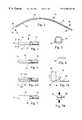
- FIG. 1is a side view of one form of an electrode in accordance with the invention.
- FIG. 2is an enlarged top view of the working end of the electrode of FIG. 1;
- FIG. 3is an enlarged end view of the working end of the electrode of FIG. 1 taken along the line 3 — 3 ;
- FIGS. 4, 4 A, and 5are enlarged top views of the working end of modified forms of an electrode according to the invention.
- FIG. 6is a top view of the working end of another modified form of an electrode according to the invention.
- FIGS. 7A and 7Bare schematic views illustrating how the electrode depicted in FIG. 1 can be manufactured
- FIGS. 8A and 8Bare schematic views illustrating how the electrode of FIG. 1 can be used to perform an ELF procedure.
- FIG. 1is a side view of one form of an electrode 10 in accordance with the invention.
- FIG. 8Ashows the electrode of FIG. 1 mounted in a suction handpiece 12 of the type described and illustrated in U.S. Pat. No. 5,196,007. The reader is directed to the referenced patent for the details of the handpiece 12 which will assist in understanding its internal construction and how the electrode 10 is held and supplied with suction when desired. Suffice to say for present purposes, the handpiece handle 14 is hollow and is connected at its right end to a suction hose 16 (see FIG. 8A) connected to a suitable source 18 of suction.
- a cable 20 connected to a suitable source 22 of electrosurgical currentsis connected at the left hand side of the handpiece 12 via a connector 24 to an internal electrically-conductive tube (not shown) which can receive and hold and electrically connect to the bare shank end 26 of the electrode 10 and which can also convey the suction to the left hand side of the handpiece and the electrode.
- the electrode 10 shown in FIG. 1comprises a hollow tubular member 28 , for example of brass, which extends from the bare shank end 26 on the right side to a working end 30 on the left side of the figure having a bare tip 32 .
- the working end 30has a generally flat spade-like shape having preferably a width of about 0.1-0.2 inches, a length of about 0.5-0.9 inches, and a thickness of about 0.01-0.03 inches.
- the length of the bare tip 32is about 0.04-0.2 inches.
- the length dimensionis the dimension in the direction of the longitudinal or long axis of the electrode 10 .
- the electrode 10is made from a straight tube by bending about a mandrel having a radius of curvature of about 4.5 inches leaving two straight end sections 34 .
- the overall length of the electrode 10is about 5.5-8.5 inches.
- FIGS. 7A and 7DA preferred way of fabricating the electrode 10 is illustrated in FIGS. 7A and 7D.
- the starting pointis a stiff straight brass tube 36 of the required length.
- One end, left bare,serves as the shank 26 .
- the other endis subjected to two cutting or grinding operations.
- the firstillustrated in FIG. 7A, grinds 40 straight down from the top to remove roughly 1 ⁇ 4-1 ⁇ 2 inches of the tube end over a distance approximately equal to the length of the spade end.
- the secondalso illustrated in FIG. 7A, grinds 42 at roughly a 45° angle to form a 45° slant at the remaining open end 44 of the tube.
- the slightly curved bottom part 46 of the tube end leftis then flattened in a vise 48 as shown in FIG. 7 B.
- the free end of the resultant spade-shaped bodymay be bevelled to provide a bevelled edge as shown in FIG. 2 at 50 , or alternatively bevelled as well as ground to a point as shown at FIG. 4 at 52 . If desired the edges of the straight end can be rounded as shown at 54 in FIG. 6 .
- an electrically-insulating coating 56is deposited over all of the spade end except for the bare tip 32 . With the pointed end 52 , the coating 56 preferably covers up to the beginning of the point. Fused powdered Teflon can be used for this purpose.
- a heat shrinkable plastic tube 58is provided to encircle the entire length of the tube except for the spade end and the shank end 26 . Finally, the electrode is bent around a mandrel to give it the final curved shape desired.
- FIGS. 8A and 8Billustrate schematically how the electrode is used in conducting an ELF procedure, and the significance of the spade end construction and the shape and construction of the electrode will become clearer. In this procedure, only the steps to explain how the electrode 10 carries out its tasks are given, but it will be understood that many other steps having to do with preparing the patient and anchoring the forehead scalp after severing of the muscle have been omitted for brevity.
- the scalpis perforated 60 (also referred to as a central incision) above the brow 62 , and an endoscope probe 64 , as shown, inserted so that the surgeon can visualize the progress of the procedure.
- the blunt edge of the endoscope probeis then used with blunt dissection to move tissue to provide a space between the scalp and skull within which the electrode will be inserted and that will allow the surgeon to visualize the actions of the inserted electrode.
- the electrode 10is inserted from above, typically by way of a lateral incision 66 , and advanced down in the space between the scalp and the skull toward the brow 62 as shown.
- the electrode 10is not activated, nor is the suction.
- the tissues binding the scalp to the skullare displaced. This is continued until the muscle to be severed is reached, approximately 3-6 inches below the initial perforation.
- the suction 18is energized providing suction at the open end 44 of the tubular member adjoining the spade end and the electrosurgical apparatus 22 is activated while the surgeon manipulates the electrode end with its bare tip 32 to sever the muscle by the emitted electrosurgical currents.
- the smoke or vapor generated by the electrically cut tissuewhich would normally obstruct the surgeon's vision, is exhausted via the end tube opening 44 and the incorporated tube 28 inside the electrode 10 to the suction apparatus via the hollow handpiece 10 .
- the electrode 10may then be withdrawn and the rest of the procedure followed.
- the advantages of the electrode of the invention in carrying out this procedureinclude: cutting of the muscle using electrosurgical currents will simultaneously allow coagulation of any bleeders; typically only a single instrument, the electrode of the invention, is needed, in contrast with the need to use a number of different instruments when an ordinary scalpel is used.
- Electrode describedis particularly suitable for implementing the ELF procedure, those skilled in this art will recognize that other procedures that involve plastic surgery such as face or body lifts or other cosmetic procedures will also find the electrode of the invention helpful in reducing training time, reducing operative time, and thus reducing the cost of these surgical procedures.
- the part of the spade-shaped end adjacent the cut end of the tubular memberis coated with an electrically-insulating coating 56 leaving only the tip 32 bare for supplying electrosurgical currents to the tissue.
- the entire spade-endis left bare as illustrated at 60 in FIG. 5 .
- the electrode otherwiseis the same as that of FIG. 1 .
- the darker areas adjacent the bare tip 32 in FIG. 1, designated 56 and 58are used to represent the electrically-insulating coatings.
- FIG. 8Bshows the use of the pointed end electrode 52 of FIG. 4 used in the described procedure.
- the front edge of both electrodes while thinis preferably not sharpened to a sharp cutting edge to avoid cutting the tissue holding the scalp to the skull when the electrode 10 is pushed down to the brow.
- the downward movementuses blunt dissection to move through the tissue.
- the thin electrically-insulating coating 56covers both of the flat sides where shown as well as the side edges of part of the spade-shaped end 30 , the dividing line between the coated and bare sections extending transversely to the long axis of the electrode 10 .
- FIG. 4Ashows another preferred embodiment. In this case, the dividing line between the coated 56 A and bare 32 A sections extends parallel to the long axis of the electrode 10 .
- the longitudinally-extending coated section 70covers both sides and one edge of the spade-shaped end.
- the longitudinally-extending bare section 72on both sides and the other edge, extends from the tip to the open bore 44 .
- the electrosurgical currentsare emitted from the bare side edge 32 A of the electrode, thus allowing the surgeon to cut tissue with a sideways movement of the working end 30 of the electrode.
- Any electrosurgical apparatus 22can be used.
- a preferred apparatusis available from Ellman International of Hewlett, N.Y. as Model IEC50 or IEC100.
- the insulating coatings 56 , 58will prevent accidental touching of patient tissue by the electrode sides, so that the electrosurgical currents are locallized to the bare electrode end 32 .
- the apparatus used in the procedurepreferably generates electrosurgical currents with a frequency of about 2.5-4 MHz, with 4 MHz preferred.
Landscapes
- Health & Medical Sciences (AREA)
- Surgery (AREA)
- Engineering & Computer Science (AREA)
- Life Sciences & Earth Sciences (AREA)
- Biomedical Technology (AREA)
- Otolaryngology (AREA)
- Nuclear Medicine, Radiotherapy & Molecular Imaging (AREA)
- Plasma & Fusion (AREA)
- Physics & Mathematics (AREA)
- Heart & Thoracic Surgery (AREA)
- Medical Informatics (AREA)
- Molecular Biology (AREA)
- Animal Behavior & Ethology (AREA)
- General Health & Medical Sciences (AREA)
- Public Health (AREA)
- Veterinary Medicine (AREA)
- Surgical Instruments (AREA)
Abstract
Description
This invention relates to an electrosurgical electrode, and in particular to an electrosurgical electrode for performing a surgical procedure known as an Endoscope Forehead Lift (EFL).
In the EFL procedure that is pertinent to this invention, via endoscopic visualization, a muscle extending over the brow and contributing to skin wrinkling due to excessive pulling forces on the skin is severed at least in part. Access to the muscle is obtained via a hole formed in the scalp at a position about three or so inches above the brow, and extending a probe with a thin edge through the hole and down via a tunnel forced between the scalp and the skull to the muscle to sever part or all of the same. If properly done, this should relieve the excessive pulling forces tending to smooth the forehead skin. See “Endoscopic Plastic Surgery”, by Bostwick III, Eaves III, and Nahai, published by Quality Medical Publishing, Inc. of St. Louis Mo., 1995, Pgs. 166-170, the contents of which are hereby incorporated by reference, for a description of the procedure and how it works.
The present invention describes a novel electrosurgical electrode that can be used to perform the EFL and similar procedures simpler and with fewer side effects than other techniques.
Briefly stated, the novel electrode comprises an elongated thin, electrically-conductive tubular member shaped to substantially follow the curvature of the skull extending from the brow upward to a position at or above the hairline. The electrically-conductive tubular member terminates at a distal end in a generally spade-shaped end whose tip is bare. The remainder of the electrically-conductive tubular member is covered with an electrically-insulating coating. The proximal end of the electrically-conductive tubular member is connected to a handpiece whose interior is hollow and which can be connected to a flexible suction tube coupled to a source of suction. Also connected to the handpiece is a connector which makes a good electrically-conductive contact to the electrically-conductive tubular member. The connector in turn is provided with a cable that can be plugged into conventional electrosurgical apparatus. During the part of the procedure when the muscle is severed by activating the electrosurgical apparatus, the suction source can also be activated to remove any smoke or vapor that can interfere with the surgeon's view of the cutting action.
In a preferred embodiment, most of the spade-shaped end, both sides and edges, adjacent the tubular member is covered with a thin coating of an electrically-insulating coating leaving only a bare tip capable of supplying electrosurgical currents to tissue.
The handpiece can be of the type described in our U.S. Pat. No. 5,196,007, whose contents are hereby incorporated by reference, and which describes a handpiece which combines electrosurgical currents at a working end of an electrode together with suction at the same working end supplied via a hollow handpiece. The patent nowhere describes its application to the EFL procedure, and the electrodes described in the patent are not suitable for carrying out the EFL procedure.
The various features of novelty which characterize the invention are pointed out with particularity in the claims annexed to and forming a part of this disclosure. For a better understanding of the invention, its operating advantages and specific objects attained by its use, reference should be had to the accompanying drawings and descriptive matter in which there are illustrated and described the preferred embodiments of the invention.
In the drawings:
FIG. 1 is a side view of one form of an electrode in accordance with the invention;
FIG. 2 is an enlarged top view of the working end of the electrode of FIG. 1;
FIG. 3 is an enlarged end view of the working end of the electrode of FIG. 1 taken along theline 3—3;
FIGS. 4,4A, and5 are enlarged top views of the working end of modified forms of an electrode according to the invention;
FIG. 6 is a top view of the working end of another modified form of an electrode according to the invention;
FIGS. 7A and 7B are schematic views illustrating how the electrode depicted in FIG. 1 can be manufactured;
FIGS. 8A and 8B are schematic views illustrating how the electrode of FIG. 1 can be used to perform an ELF procedure.
FIG. 1 is a side view of one form of anelectrode 10 in accordance with the invention. FIG. 8A shows the electrode of FIG. 1 mounted in asuction handpiece 12 of the type described and illustrated in U.S. Pat. No. 5,196,007. The reader is directed to the referenced patent for the details of thehandpiece 12 which will assist in understanding its internal construction and how theelectrode 10 is held and supplied with suction when desired. Suffice to say for present purposes, thehandpiece handle 14 is hollow and is connected at its right end to a suction hose16 (see FIG. 8A) connected to asuitable source 18 of suction. Acable 20 connected to asuitable source 22 of electrosurgical currents is connected at the left hand side of thehandpiece 12 via aconnector 24 to an internal electrically-conductive tube (not shown) which can receive and hold and electrically connect to thebare shank end 26 of theelectrode 10 and which can also convey the suction to the left hand side of the handpiece and the electrode.
Theelectrode 10 shown in FIG. 1 comprises a hollowtubular member 28, for example of brass, which extends from thebare shank end 26 on the right side to a workingend 30 on the left side of the figure having abare tip 32. The workingend 30 has a generally flat spade-like shape having preferably a width of about 0.1-0.2 inches, a length of about 0.5-0.9 inches, and a thickness of about 0.01-0.03 inches. The length of thebare tip 32 is about 0.04-0.2 inches. The length dimension is the dimension in the direction of the longitudinal or long axis of theelectrode 10. Theelectrode 10 is made from a straight tube by bending about a mandrel having a radius of curvature of about 4.5 inches leaving twostraight end sections 34. The overall length of theelectrode 10 is about 5.5-8.5 inches.
A preferred way of fabricating theelectrode 10 is illustrated in FIGS. 7A and 7D. The starting point is a stiffstraight brass tube 36 of the required length. One end, left bare, serves as theshank 26. The other end is subjected to two cutting or grinding operations. The first, illustrated in FIG. 7A, grinds40 straight down from the top to remove roughly ¼-½ inches of the tube end over a distance approximately equal to the length of the spade end. The second, also illustrated in FIG. 7A, grinds42 at roughly a 45° angle to form a 45° slant at the remainingopen end 44 of the tube. The slightlycurved bottom part 46 of the tube end left is then flattened in avise 48 as shown in FIG.7B. Next, the free end of the resultant spade-shaped body may be bevelled to provide a bevelled edge as shown in FIG. 2 at50, or alternatively bevelled as well as ground to a point as shown at FIG. 4 at52. If desired the edges of the straight end can be rounded as shown at54 in FIG.6. Then an electrically-insulatingcoating 56 is deposited over all of the spade end except for thebare tip 32. With thepointed end 52, thecoating 56 preferably covers up to the beginning of the point. Fused powdered Teflon can be used for this purpose. Next, a heat shrinkableplastic tube 58 is provided to encircle the entire length of the tube except for the spade end and theshank end 26. Finally, the electrode is bent around a mandrel to give it the final curved shape desired.
FIGS. 8A and 8B illustrate schematically how the electrode is used in conducting an ELF procedure, and the significance of the spade end construction and the shape and construction of the electrode will become clearer. In this procedure, only the steps to explain how theelectrode 10 carries out its tasks are given, but it will be understood that many other steps having to do with preparing the patient and anchoring the forehead scalp after severing of the muscle have been omitted for brevity.
Essentially, the scalp is perforated60 (also referred to as a central incision) above thebrow 62, and anendoscope probe 64, as shown, inserted so that the surgeon can visualize the progress of the procedure. Typically, the blunt edge of the endoscope probe is then used with blunt dissection to move tissue to provide a space between the scalp and skull within which the electrode will be inserted and that will allow the surgeon to visualize the actions of the inserted electrode. Then theelectrode 10 is inserted from above, typically by way of alateral incision 66, and advanced down in the space between the scalp and the skull toward thebrow 62 as shown. Theelectrode 10 is not activated, nor is the suction. By a process of blunt dissection using thefront edge 50 of the electrode, as the surgeon advances theelectrode 10, the tissues binding the scalp to the skull are displaced. This is continued until the muscle to be severed is reached, approximately 3-6 inches below the initial perforation. Then thesuction 18 is energized providing suction at theopen end 44 of the tubular member adjoining the spade end and theelectrosurgical apparatus 22 is activated while the surgeon manipulates the electrode end with itsbare tip 32 to sever the muscle by the emitted electrosurgical currents. The smoke or vapor generated by the electrically cut tissue, which would normally obstruct the surgeon's vision, is exhausted via theend tube opening 44 and the incorporatedtube 28 inside theelectrode 10 to the suction apparatus via thehollow handpiece 10. Theelectrode 10 may then be withdrawn and the rest of the procedure followed.
The advantages of the electrode of the invention in carrying out this procedure include: cutting of the muscle using electrosurgical currents will simultaneously allow coagulation of any bleeders; typically only a single instrument, the electrode of the invention, is needed, in contrast with the need to use a number of different instruments when an ordinary scalpel is used.
While the electrode described is particularly suitable for implementing the ELF procedure, those skilled in this art will recognize that other procedures that involve plastic surgery such as face or body lifts or other cosmetic procedures will also find the electrode of the invention helpful in reducing training time, reducing operative time, and thus reducing the cost of these surgical procedures.
In the preferred embodiment, the part of the spade-shaped end adjacent the cut end of the tubular member is coated with an electrically-insulatingcoating 56 leaving only thetip 32 bare for supplying electrosurgical currents to the tissue. In a modification that may find use in other similar procedures, the entire spade-end is left bare as illustrated at60 in FIG.5. The electrode otherwise is the same as that of FIG.1. The darker areas adjacent thebare tip 32 in FIG. 1, designated56 and58, are used to represent the electrically-insulating coatings. FIG. 8B shows the use of thepointed end electrode 52 of FIG. 4 used in the described procedure. The front edge of both electrodes while thin is preferably not sharpened to a sharp cutting edge to avoid cutting the tissue holding the scalp to the skull when theelectrode 10 is pushed down to the brow. The downward movement uses blunt dissection to move through the tissue.
In the preceding embodiments, the thin electrically-insulatingcoating 56 covers both of the flat sides where shown as well as the side edges of part of the spade-shapedend 30, the dividing line between the coated and bare sections extending transversely to the long axis of theelectrode 10. FIG. 4A shows another preferred embodiment. In this case, the dividing line between the coated56A and bare32A sections extends parallel to the long axis of theelectrode 10. The longitudinally-extendingcoated section 70 covers both sides and one edge of the spade-shaped end. The longitudinally-extendingbare section 72, on both sides and the other edge, extends from the tip to theopen bore 44. Thus, the electrosurgical currents are emitted from thebare side edge 32A of the electrode, thus allowing the surgeon to cut tissue with a sideways movement of the workingend 30 of the electrode.
Anyelectrosurgical apparatus 22 can be used. A preferred apparatus is available from Ellman International of Hewlett, N.Y. as Model IEC50 or IEC100.
The insulatingcoatings bare electrode end 32.
The apparatus used in the procedure preferably generates electrosurgical currents with a frequency of about 2.5-4 MHz, with 4 MHz preferred.
While the invention has been described in connection with preferred embodiments, it will be understood that modifications thereof within the principles outlined above will be evident to those skilled in the art and thus the invention is not limited to the preferred embodiments but is intended to encompass such modifications.
Claims (16)
1. An electrosurgical electrode for performing an EFL procedure on the forehead of a human patient wherein under endoscopic visualization an electrode inserted above the brow is forced through a space formed between the scalp and the skull until reaching a muscle extending over the brow and severing the muscle with electrosurgical currents supplied by electrosurgical apparatus connected to the electrode, the electrode comprising:
(a) an elongated electrically-conductive tubular member having at a first end means for connecting to electrosurgical apparatus and having at a second end a tip with an opening that serves as the working end of the electrode and adjacent the tip an electrode portion,
(b) the electrode portion adjacent the tip being generally spade-shaped and comprising, in order, an electrically-conductive active first section and a second section, the first and second sections extending in a straight line aligned with the immediately-adjacent portion of the tubular member,
(c) the active first section being bare so as to allow electrosurgical currents to enter contacted tissue when the electrosurgical apparatus is activated,
(d) the second section having a thin electrically-insulating coating so as to prevent electrosurgical currents to enter contacted tissue when the electrosurgical apparatus is activated,
(e) the tubular member comprising a duct leading to the opening for connection to a source of suction,
(f) the tubular member having a generally curved shape that follows the curvature of the forehead of a patient such that the electrode can be inserted into the space between the scalp and skull at the forehead and advanced until a muscle under the brow is reached and the muscle severed with electrosurgical currents by activating the electrosurgical apparatus while activating the source of suction to remove any smoke or plume.
2. The electrosurgical electrode as claimed in claim1, wherein the spade-shaped electrode portion is an integral extension of the tubular member made by at least a cutting step such that the tubular end adjacent the cut provides the opening that remains unobstructed for the flow of suction.
3. The electrosurgical electrode as claimed in claim1, wherein the overall length of the tubular member is about 5.5-8.5 inches.
4. The electrosurgical electrode as claimed in claim1, wherein the tubular member comprises straight end sections and a curved center section having a radius of curvature of about 3.5-5.5 inches.
5. The electrosurgical electrode as claimed in claim1, wherein the tubular member is made of brass.
6. The electrosurgical electrode as claimed in claim1 wherein the spade-shaped end has a width of about 0.1-0.2 inches.
7. The electrosurgical electrode as claimed in claim1 wherein the first section of the spade-shaped end has a length of about 0.04-0.2 inches.
8. The electrosurgical electrode as claimed in claim1, wherein the second section of the spade-shaped end has a length of about 0.5-0.9 inches.
9. The electrosurgical electrode as claimed in claim1, wherein the first section has a tip that is beveled but blunt.
10. The electrosurgical electrode as claimed in claim1, wherein the first section has a tip that is straight or pointed or rounded.
11. The electrosurgical electrode as claimed in claim1, wherein the second section is separated from the first section by a dividing line extending transversely to a long axis of the electrode.
12. The electrosurgical electrode as claimed in claim1, wherein the second section is separated from the first section by a dividing line extending parallel to a long axis of the electrode.
13. The method for making an electrosurgical electrode for performing an ELF procedure on the forehead of a patient, said electrosurgical electrode comprising:
(a) an elongated electrically-conductive tubular member having at a first end means for connecting to the first means of the handpiece and having at a second end a tip with an opening that serves as the working end of the electrode and adjacent the tip an electrode portion,
(b) the electrode portion adjacent the tip being generally spade-shaped and comprising, in order, an electrically-conductive active first section and an electrically-insulated second section,
(c) the active first section being bare so as to allow electrosurgical currents to enter contacted tissue when the electrosurgical apparatus is activated,
(d) the second section having a relatively thin electrically-insulating coating so as to prevent electrosurgical currents to enter contacted tissue when the electrosurgical apparatus is activated,
(e) said method comprising:
i) providing an elongated metal tube,
ii) cutting the end of the tube transversely and at an angle to form the generally spade-shaped working end with the opening,
iii) providing an electrically-insulating coating over the elongated metal tube and the spade-shaped working end except for a small part adjacent the tip,
iv) shaping the elongated metal tube to follow the contour of the forehead of a patient.
14. The method of claim13, wherein, following step (e)(ii), the cut end is subjected to a flattening operation.
15. A method for performing an electrosurgical EFL procedure on the forehead of a human patient, comprising the steps:
A) inserting an endoscopic probe into a space formed between the scalp and the skull for visualizing muscle tissue extending over the brow,
B) providing a source of suction,
C) providing electrosurgical apparatus for generating electrosurgical currents and an electrosurgical electrode connected to the apparatus and comprising:
(a) an elongated electrically-conductive tubular member having at a first end means for connecting to the electrosurgical apparatus and having at a second end a tip with an opening that serves as the working end of the electrode and adjacent the tip an electrode portion,
(b) the electrode portion adjacent the tip being generally spade-shaped and comprising, in order, an electrically-conductive active first section and a second section, the first and second sections extending in a straight line aligned with the immediately-adjacent portion of the tubular member,
(c) the active first section being bare so as to allow electrosurgical currents to enter contacted tissue when the electrosurgical apparatus is activated,
(d) the second section having a relatively thin electrically-insulating coating so as to prevent electrosurgical currents to enter contacted tissue when the electrosurgical apparatus is activated,
(e) the tubular member comprising a duct leading to the opening for connection to the source of suction,
(f) the tubular member having a generally curved shape that follows the curvature of the forehead of the patient,
D) using blunt dissection inserting the electrode from above the brow into the space formed between the scalp and the skull until reaching the muscle tissue extending over the brow.
E) activating the electrosurgical apparatus and the source of suction and cutting the muscle tissue with electrosurgical currents from the active first section while suction is provided within the space via the opening to remove any plumes resulting from cutting of the tissue.
16. The electrosurgical electrode as claimed in claim15, wherein the overall length of the tubular member is about 5.5-8.5 inches.
Priority Applications (1)
| Application Number | Priority Date | Filing Date | Title |
|---|---|---|---|
| US09/442,315US6306135B1 (en) | 1999-11-22 | 1999-11-22 | Forehead lift suction probe |
Applications Claiming Priority (1)
| Application Number | Priority Date | Filing Date | Title |
|---|---|---|---|
| US09/442,315US6306135B1 (en) | 1999-11-22 | 1999-11-22 | Forehead lift suction probe |
Publications (1)
| Publication Number | Publication Date |
|---|---|
| US6306135B1true US6306135B1 (en) | 2001-10-23 |
Family
ID=23756350
Family Applications (1)
| Application Number | Title | Priority Date | Filing Date |
|---|---|---|---|
| US09/442,315Expired - Fee RelatedUS6306135B1 (en) | 1999-11-22 | 1999-11-22 | Forehead lift suction probe |
Country Status (1)
| Country | Link |
|---|---|
| US (1) | US6306135B1 (en) |
Cited By (36)
| Publication number | Priority date | Publication date | Assignee | Title |
|---|---|---|---|---|
| US20060184242A1 (en)* | 2003-10-20 | 2006-08-17 | Samuel Lichtenstein | Method and apparatus for percutaneous reduction of anterior-posterior diameter of mitral valve |
| US7749249B2 (en) | 2006-02-21 | 2010-07-06 | Kardium Inc. | Method and device for closing holes in tissue |
| US7837610B2 (en) | 2006-08-02 | 2010-11-23 | Kardium Inc. | System for improving diastolic dysfunction |
| US20110054461A1 (en)* | 2009-09-02 | 2011-03-03 | Tyco Healthcare Group Lp | Electrosurgical Electrode with Insulative Coating |
| US8150499B2 (en) | 2006-05-19 | 2012-04-03 | Kardium Inc. | Automatic atherectomy system |
| US8449605B2 (en) | 2006-06-28 | 2013-05-28 | Kardium Inc. | Method for anchoring a mitral valve |
| US8489172B2 (en) | 2008-01-25 | 2013-07-16 | Kardium Inc. | Liposuction system |
| USD709196S1 (en) | 2013-03-15 | 2014-07-15 | Megadyne Medical Products, Inc. | Hand piece |
| USD713027S1 (en)* | 2013-04-22 | 2014-09-09 | Jason P. Adams | Suction probe |
| US8882767B2 (en) | 2009-04-24 | 2014-11-11 | Megadyne Medical Products, Inc. | Electrosurgical instrument with adjustable utility conduit |
| US8882768B2 (en) | 2009-04-24 | 2014-11-11 | Megadyne Medical Products, Inc. | Hand piece with adjustable utility conduit |
| US8906011B2 (en) | 2007-11-16 | 2014-12-09 | Kardium Inc. | Medical device for use in bodily lumens, for example an atrium |
| US8920411B2 (en) | 2006-06-28 | 2014-12-30 | Kardium Inc. | Apparatus and method for intra-cardiac mapping and ablation |
| US8940002B2 (en) | 2010-09-30 | 2015-01-27 | Kardium Inc. | Tissue anchor system |
| US9011423B2 (en) | 2012-05-21 | 2015-04-21 | Kardium, Inc. | Systems and methods for selecting, activating, or selecting and activating transducers |
| US9050066B2 (en) | 2010-06-07 | 2015-06-09 | Kardium Inc. | Closing openings in anatomical tissue |
| US9072511B2 (en) | 2011-03-25 | 2015-07-07 | Kardium Inc. | Medical kit for constricting tissue or a bodily orifice, for example, a mitral valve |
| US9119633B2 (en) | 2006-06-28 | 2015-09-01 | Kardium Inc. | Apparatus and method for intra-cardiac mapping and ablation |
| US9198592B2 (en) | 2012-05-21 | 2015-12-01 | Kardium Inc. | Systems and methods for activating transducers |
| US9204964B2 (en) | 2009-10-01 | 2015-12-08 | Kardium Inc. | Medical device, kit and method for constricting tissue or a bodily orifice, for example, a mitral valve |
| US9259260B2 (en) | 2013-03-14 | 2016-02-16 | Megadyne Medical Products, Inc. | Fluid evacuation device |
| US9375253B2 (en) | 2013-03-14 | 2016-06-28 | Megadyne Medical Products, Inc. | Electrosurgical instrument |
| US9452016B2 (en) | 2011-01-21 | 2016-09-27 | Kardium Inc. | Catheter system |
| US9480525B2 (en) | 2011-01-21 | 2016-11-01 | Kardium, Inc. | High-density electrode-based medical device system |
| US9492227B2 (en) | 2011-01-21 | 2016-11-15 | Kardium Inc. | Enhanced medical device for use in bodily cavities, for example an atrium |
| USD777926S1 (en) | 2012-01-20 | 2017-01-31 | Kardium Inc. | Intra-cardiac procedure device |
| USD777925S1 (en) | 2012-01-20 | 2017-01-31 | Kardium Inc. | Intra-cardiac procedure device |
| US9744038B2 (en) | 2008-05-13 | 2017-08-29 | Kardium Inc. | Medical device for constricting tissue or a bodily orifice, for example a mitral valve |
| US10028783B2 (en) | 2006-06-28 | 2018-07-24 | Kardium Inc. | Apparatus and method for intra-cardiac mapping and ablation |
| US10028762B1 (en)* | 2013-10-14 | 2018-07-24 | Percutaneous Cosmetic Devices LLC | Method of cutting soft tissue under facial skin |
| US10368936B2 (en) | 2014-11-17 | 2019-08-06 | Kardium Inc. | Systems and methods for selecting, activating, or selecting and activating transducers |
| US10722184B2 (en) | 2014-11-17 | 2020-07-28 | Kardium Inc. | Systems and methods for selecting, activating, or selecting and activating transducers |
| US10827977B2 (en) | 2012-05-21 | 2020-11-10 | Kardium Inc. | Systems and methods for activating transducers |
| US11259867B2 (en) | 2011-01-21 | 2022-03-01 | Kardium Inc. | High-density electrode-based medical device system |
| US11389232B2 (en) | 2006-06-28 | 2022-07-19 | Kardium Inc. | Apparatus and method for intra-cardiac mapping and ablation |
| CN116549096A (en)* | 2023-05-18 | 2023-08-08 | 浙江舒友仪器设备股份有限公司 | Visual smoking sword of flexible light source |
Citations (15)
| Publication number | Priority date | Publication date | Assignee | Title |
|---|---|---|---|---|
| US3974833A (en)* | 1973-03-19 | 1976-08-17 | Durden Iii John G | Disposable electrosurgical cautery having optional suction control feature |
| US5196007A (en) | 1991-06-07 | 1993-03-23 | Alan Ellman | Electrosurgical handpiece with activator |
| US5395312A (en)* | 1991-10-18 | 1995-03-07 | Desai; Ashvin | Surgical tool |
| US5452732A (en)* | 1994-04-26 | 1995-09-26 | Bircoll; Mel | Method of dissecting along connective tissue lines |
| US5486161A (en)* | 1993-02-02 | 1996-01-23 | Zomed International | Medical probe device and method |
| US5496314A (en)* | 1992-05-01 | 1996-03-05 | Hemostatic Surgery Corporation | Irrigation and shroud arrangement for electrically powered endoscopic probes |
| US5733283A (en)* | 1996-06-05 | 1998-03-31 | Malis; Jerry L. | Flat loop bipolar electrode tips for electrosurgical instrument |
| US5746762A (en)* | 1996-06-24 | 1998-05-05 | Bass; Lawrence S. | Device and method for surgical flap dissection |
| US5766167A (en)* | 1993-12-17 | 1998-06-16 | United States Surgical Corporation | Monopolar electrosurgical Instruments |
| US5785705A (en)* | 1994-10-11 | 1998-07-28 | Oratec Interventions, Inc. | RF method for controlled depth ablation of soft tissue |
| US5807385A (en)* | 1993-08-02 | 1998-09-15 | Keller; Gregory S. | Method of laser cosmetic surgery |
| US5830214A (en)* | 1994-11-08 | 1998-11-03 | Heartport, Inc. | Fluid-evacuating electrosurgical device |
| US5935142A (en)* | 1992-02-20 | 1999-08-10 | Hood; Larry L. | Cavitation-assisted method of material separation |
| US5950633A (en)* | 1997-10-02 | 1999-09-14 | Ethicon, Inc. | Microsurgical technique for cosmetic surgery |
| US6139559A (en)* | 1998-04-07 | 2000-10-31 | Nordan; Lee T. | Surgical blade |
- 1999
- 1999-11-22USUS09/442,315patent/US6306135B1/ennot_activeExpired - Fee Related
Patent Citations (16)
| Publication number | Priority date | Publication date | Assignee | Title |
|---|---|---|---|---|
| US3974833A (en)* | 1973-03-19 | 1976-08-17 | Durden Iii John G | Disposable electrosurgical cautery having optional suction control feature |
| US5196007A (en) | 1991-06-07 | 1993-03-23 | Alan Ellman | Electrosurgical handpiece with activator |
| US5395312A (en)* | 1991-10-18 | 1995-03-07 | Desai; Ashvin | Surgical tool |
| US5935142A (en)* | 1992-02-20 | 1999-08-10 | Hood; Larry L. | Cavitation-assisted method of material separation |
| US5496314A (en)* | 1992-05-01 | 1996-03-05 | Hemostatic Surgery Corporation | Irrigation and shroud arrangement for electrically powered endoscopic probes |
| US5486161A (en)* | 1993-02-02 | 1996-01-23 | Zomed International | Medical probe device and method |
| US5807385A (en)* | 1993-08-02 | 1998-09-15 | Keller; Gregory S. | Method of laser cosmetic surgery |
| US5766167A (en)* | 1993-12-17 | 1998-06-16 | United States Surgical Corporation | Monopolar electrosurgical Instruments |
| US5452732A (en)* | 1994-04-26 | 1995-09-26 | Bircoll; Mel | Method of dissecting along connective tissue lines |
| US5549625A (en)* | 1994-04-26 | 1996-08-27 | Very Inventive Physicians, Inc. | Balloon dissector |
| US5785705A (en)* | 1994-10-11 | 1998-07-28 | Oratec Interventions, Inc. | RF method for controlled depth ablation of soft tissue |
| US5830214A (en)* | 1994-11-08 | 1998-11-03 | Heartport, Inc. | Fluid-evacuating electrosurgical device |
| US5733283A (en)* | 1996-06-05 | 1998-03-31 | Malis; Jerry L. | Flat loop bipolar electrode tips for electrosurgical instrument |
| US5746762A (en)* | 1996-06-24 | 1998-05-05 | Bass; Lawrence S. | Device and method for surgical flap dissection |
| US5950633A (en)* | 1997-10-02 | 1999-09-14 | Ethicon, Inc. | Microsurgical technique for cosmetic surgery |
| US6139559A (en)* | 1998-04-07 | 2000-10-31 | Nordan; Lee T. | Surgical blade |
Non-Patent Citations (1)
| Title |
|---|
| Endoscopic Plastic Surgery, by Bostwick III, Eaves III, and Nahi, published 1995 by Quality Medical Publishing, Inc. of St. Louis, Missouri, pp. 166-170. |
Cited By (124)
| Publication number | Priority date | Publication date | Assignee | Title |
|---|---|---|---|---|
| US20060184242A1 (en)* | 2003-10-20 | 2006-08-17 | Samuel Lichtenstein | Method and apparatus for percutaneous reduction of anterior-posterior diameter of mitral valve |
| US8337524B2 (en) | 2006-02-21 | 2012-12-25 | Kardium Inc. | Method and device for closing holes in tissue |
| US9572557B2 (en) | 2006-02-21 | 2017-02-21 | Kardium Inc. | Method and device for closing holes in tissue |
| US7749249B2 (en) | 2006-02-21 | 2010-07-06 | Kardium Inc. | Method and device for closing holes in tissue |
| US8150499B2 (en) | 2006-05-19 | 2012-04-03 | Kardium Inc. | Automatic atherectomy system |
| US8532746B2 (en) | 2006-05-19 | 2013-09-10 | Kardium Inc. | Automatic atherectomy system |
| US11389231B2 (en) | 2006-06-28 | 2022-07-19 | Kardium Inc. | Apparatus and method for intra-cardiac mapping and ablation |
| US10828094B2 (en) | 2006-06-28 | 2020-11-10 | Kardium Inc. | Apparatus and method for intra-cardiac mapping and ablation |
| US10028783B2 (en) | 2006-06-28 | 2018-07-24 | Kardium Inc. | Apparatus and method for intra-cardiac mapping and ablation |
| US9119634B2 (en) | 2006-06-28 | 2015-09-01 | Kardium Inc. | Apparatus and method for intra-cardiac mapping and ablation |
| US11389232B2 (en) | 2006-06-28 | 2022-07-19 | Kardium Inc. | Apparatus and method for intra-cardiac mapping and ablation |
| US9119633B2 (en) | 2006-06-28 | 2015-09-01 | Kardium Inc. | Apparatus and method for intra-cardiac mapping and ablation |
| US10820941B2 (en) | 2006-06-28 | 2020-11-03 | Kardium Inc. | Apparatus and method for intra-cardiac mapping and ablation |
| US8672998B2 (en) | 2006-06-28 | 2014-03-18 | Kardium Inc. | Method for anchoring a mitral valve |
| US11399890B2 (en) | 2006-06-28 | 2022-08-02 | Kardium Inc. | Apparatus and method for intra-cardiac mapping and ablation |
| US9987083B2 (en) | 2006-06-28 | 2018-06-05 | Kardium Inc. | Apparatus and method for intra-cardiac mapping and ablation |
| US8920411B2 (en) | 2006-06-28 | 2014-12-30 | Kardium Inc. | Apparatus and method for intra-cardiac mapping and ablation |
| US9192468B2 (en) | 2006-06-28 | 2015-11-24 | Kardium Inc. | Method for anchoring a mitral valve |
| US10828093B2 (en) | 2006-06-28 | 2020-11-10 | Kardium Inc. | Apparatus and method for intra-cardiac mapping and ablation |
| US8449605B2 (en) | 2006-06-28 | 2013-05-28 | Kardium Inc. | Method for anchoring a mitral valve |
| US9987084B2 (en) | 2006-06-28 | 2018-06-05 | Kardium Inc. | Apparatus and method for intra-cardiac mapping and ablation |
| US11033392B2 (en) | 2006-08-02 | 2021-06-15 | Kardium Inc. | System for improving diastolic dysfunction |
| US7837610B2 (en) | 2006-08-02 | 2010-11-23 | Kardium Inc. | System for improving diastolic dysfunction |
| US11633231B2 (en) | 2007-11-16 | 2023-04-25 | Kardium Inc. | Medical device for use in bodily lumens, for example an atrium |
| US8906011B2 (en) | 2007-11-16 | 2014-12-09 | Kardium Inc. | Medical device for use in bodily lumens, for example an atrium |
| US11304751B2 (en) | 2007-11-16 | 2022-04-19 | Kardium Inc. | Medical device for use in bodily lumens, for example an atrium |
| US10828098B2 (en) | 2007-11-16 | 2020-11-10 | Kardium Inc. | Medical device for use in bodily lumens, for example an atrium |
| US11751940B2 (en) | 2007-11-16 | 2023-09-12 | Kardium Inc. | Medical device for use in bodily lumens, for example an atrium |
| US9877779B2 (en) | 2007-11-16 | 2018-01-30 | Kardium Inc. | Medical device for use in bodily lumens, for example an atrium |
| US10828097B2 (en) | 2007-11-16 | 2020-11-10 | Kardium Inc. | Medical device for use in bodily lumens, for example an atrium |
| US10828096B2 (en) | 2007-11-16 | 2020-11-10 | Kardium Inc. | Medical device for use in bodily lumens, for example an atrium |
| US9839474B2 (en) | 2007-11-16 | 2017-12-12 | Kardium Inc. | Medical device for use in bodily lumens, for example an atrium |
| US11432874B2 (en) | 2007-11-16 | 2022-09-06 | Kardium Inc. | Medical device for use in bodily lumens, for example an atrium |
| US11413091B2 (en) | 2007-11-16 | 2022-08-16 | Kardium Inc. | Medical device for use in bodily lumens, for example an atrium |
| US9820810B2 (en) | 2007-11-16 | 2017-11-21 | Kardium Inc. | Medical device for use in bodily lumens, for example an atrium |
| US9750569B2 (en) | 2007-11-16 | 2017-09-05 | Kardium Inc. | Medical device for use in bodily lumens, for example an atrium |
| US10828095B2 (en) | 2007-11-16 | 2020-11-10 | Kardium Inc. | Medical device for use in bodily lumens, for example an atrium |
| US10499986B2 (en) | 2007-11-16 | 2019-12-10 | Kardium Inc. | Medical device for use in bodily lumens, for example an atrium |
| US8932287B2 (en) | 2007-11-16 | 2015-01-13 | Kardium Inc. | Medical device for use in bodily lumens, for example an atrium |
| US11076913B2 (en) | 2007-11-16 | 2021-08-03 | Kardium Inc. | Medical device for use in bodily lumens, for example an atrium |
| US11801091B2 (en) | 2007-11-16 | 2023-10-31 | Kardium Inc. | Medical device for use in bodily lumens, for example an atrium |
| US11331141B2 (en) | 2007-11-16 | 2022-05-17 | Kardium Inc. | Medical device for use in bodily lumens, for example an atrium |
| US9603661B2 (en) | 2007-11-16 | 2017-03-28 | Kardium Inc. | Medical device for use in bodily lumens, for example an atrium |
| US9585717B2 (en) | 2007-11-16 | 2017-03-07 | Kardium Inc. | Medical device for use in bodily lumens, for example an atrium |
| US8489172B2 (en) | 2008-01-25 | 2013-07-16 | Kardium Inc. | Liposuction system |
| US9744038B2 (en) | 2008-05-13 | 2017-08-29 | Kardium Inc. | Medical device for constricting tissue or a bodily orifice, for example a mitral valve |
| US8882767B2 (en) | 2009-04-24 | 2014-11-11 | Megadyne Medical Products, Inc. | Electrosurgical instrument with adjustable utility conduit |
| US8882768B2 (en) | 2009-04-24 | 2014-11-11 | Megadyne Medical Products, Inc. | Hand piece with adjustable utility conduit |
| US20110054461A1 (en)* | 2009-09-02 | 2011-03-03 | Tyco Healthcare Group Lp | Electrosurgical Electrode with Insulative Coating |
| US8398625B2 (en)* | 2009-09-02 | 2013-03-19 | Covidien Lp | Electrosurgical electrode with insulative coating |
| US10813758B2 (en) | 2009-10-01 | 2020-10-27 | Kardium Inc. | Medical device, kit and method for constricting tissue or a bodily orifice, for example, a mitral valve |
| US10687941B2 (en) | 2009-10-01 | 2020-06-23 | Kardium Inc. | Medical device, kit and method for constricting tissue or a bodily orifice, for example, a mitral valve |
| US9867703B2 (en) | 2009-10-01 | 2018-01-16 | Kardium Inc. | Medical device, kit and method for constricting tissue or a bodily orifice, for example, a mitral valve |
| US9204964B2 (en) | 2009-10-01 | 2015-12-08 | Kardium Inc. | Medical device, kit and method for constricting tissue or a bodily orifice, for example, a mitral valve |
| US10603022B2 (en) | 2010-06-07 | 2020-03-31 | Kardium Inc. | Closing openings in anatomical tissue |
| US9050066B2 (en) | 2010-06-07 | 2015-06-09 | Kardium Inc. | Closing openings in anatomical tissue |
| US9918706B2 (en) | 2010-06-07 | 2018-03-20 | Kardium Inc. | Closing openings in anatomical tissue |
| US8940002B2 (en) | 2010-09-30 | 2015-01-27 | Kardium Inc. | Tissue anchor system |
| US12178490B2 (en) | 2011-01-21 | 2024-12-31 | Kardium Inc. | Enhanced medical device for use in bodily cavities, for example an atrium |
| US11298173B2 (en) | 2011-01-21 | 2022-04-12 | Kardium Inc. | Enhanced medical device for use in bodily cavities, for example an atrium |
| US9675401B2 (en) | 2011-01-21 | 2017-06-13 | Kardium Inc. | Enhanced medical device for use in bodily cavities, for example an atrium |
| US11350989B2 (en) | 2011-01-21 | 2022-06-07 | Kardium Inc. | Catheter system |
| US11259867B2 (en) | 2011-01-21 | 2022-03-01 | Kardium Inc. | High-density electrode-based medical device system |
| US9526573B2 (en) | 2011-01-21 | 2016-12-27 | Kardium Inc. | Enhanced medical device for use in bodily cavities, for example an atrium |
| US9492228B2 (en) | 2011-01-21 | 2016-11-15 | Kardium Inc. | Enhanced medical device for use in bodily cavities, for example an atrium |
| US9492227B2 (en) | 2011-01-21 | 2016-11-15 | Kardium Inc. | Enhanced medical device for use in bodily cavities, for example an atrium |
| US10485608B2 (en) | 2011-01-21 | 2019-11-26 | Kardium Inc. | Catheter system |
| US9486273B2 (en) | 2011-01-21 | 2016-11-08 | Kardium Inc. | High-density electrode-based medical device system |
| US11399881B2 (en) | 2011-01-21 | 2022-08-02 | Kardium Inc. | Enhanced medical device for use in bodily cavities, for example an atrium |
| US9480525B2 (en) | 2011-01-21 | 2016-11-01 | Kardium, Inc. | High-density electrode-based medical device system |
| US9452016B2 (en) | 2011-01-21 | 2016-09-27 | Kardium Inc. | Catheter system |
| US11596463B2 (en) | 2011-01-21 | 2023-03-07 | Kardium Inc. | Enhanced medical device for use in bodily cavities, for example an atrium |
| US11607261B2 (en) | 2011-01-21 | 2023-03-21 | Kardium Inc. | Enhanced medical device for use in bodily cavities, for example an atrium |
| US11896295B2 (en) | 2011-01-21 | 2024-02-13 | Kardium Inc. | High-density electrode-based medical device system |
| US12059202B2 (en) | 2011-01-21 | 2024-08-13 | Kardium Inc. | Catheter system |
| US12349955B2 (en) | 2011-01-21 | 2025-07-08 | Kardium Inc. | Enhanced medical device for use in bodily cavities, for example an atrium |
| US12383325B2 (en) | 2011-01-21 | 2025-08-12 | Kardium Inc. | Enhanced medical device for use in bodily cavities, for example an atrium |
| US10058318B2 (en) | 2011-03-25 | 2018-08-28 | Kardium Inc. | Medical kit for constricting tissue or a bodily orifice, for example, a mitral valve |
| US9072511B2 (en) | 2011-03-25 | 2015-07-07 | Kardium Inc. | Medical kit for constricting tissue or a bodily orifice, for example, a mitral valve |
| USD777925S1 (en) | 2012-01-20 | 2017-01-31 | Kardium Inc. | Intra-cardiac procedure device |
| USD777926S1 (en) | 2012-01-20 | 2017-01-31 | Kardium Inc. | Intra-cardiac procedure device |
| US9439713B2 (en) | 2012-05-21 | 2016-09-13 | Kardium Inc. | Systems and methods for activating transducers |
| US9259264B2 (en) | 2012-05-21 | 2016-02-16 | Kardium Inc. | Systems and methods for activating transducers |
| US10568576B2 (en) | 2012-05-21 | 2020-02-25 | Kardium Inc. | Systems and methods for activating transducers |
| US10918446B2 (en) | 2012-05-21 | 2021-02-16 | Kardium Inc. | Systems and methods for selecting, activating, or selecting and activating transducers |
| US12376796B2 (en) | 2012-05-21 | 2025-08-05 | Kardium Inc. | Systems and methods for activating transducers |
| US12376795B2 (en) | 2012-05-21 | 2025-08-05 | Kardium Inc. | Systems and methods for activating transducers |
| US10470826B2 (en) | 2012-05-21 | 2019-11-12 | Kardium Inc. | Systems and methods for selecting, activating, or selecting and activating transducers |
| US12324636B2 (en) | 2012-05-21 | 2025-06-10 | Kardium Inc. | Systems and methods for selecting, activating, or selecting and activating transducers |
| US11154248B2 (en) | 2012-05-21 | 2021-10-26 | Kardium Inc. | Systems and methods for activating transducers |
| US12226172B2 (en) | 2012-05-21 | 2025-02-18 | Kardium Inc. | Systems and methods for selecting, activating, or selecting and activating transducers |
| US9980679B2 (en) | 2012-05-21 | 2018-05-29 | Kardium Inc. | Systems and methods for activating transducers |
| US9888972B2 (en) | 2012-05-21 | 2018-02-13 | Kardium Inc. | Systems and methods for selecting, activating, or selecting and activating transducers |
| US9693832B2 (en) | 2012-05-21 | 2017-07-04 | Kardium Inc. | Systems and methods for selecting, activating, or selecting and activating transducers |
| US9572509B2 (en) | 2012-05-21 | 2017-02-21 | Kardium Inc. | Systems and methods for activating transducers |
| US9011423B2 (en) | 2012-05-21 | 2015-04-21 | Kardium, Inc. | Systems and methods for selecting, activating, or selecting and activating transducers |
| US9017321B2 (en) | 2012-05-21 | 2015-04-28 | Kardium, Inc. | Systems and methods for activating transducers |
| US9532831B2 (en) | 2012-05-21 | 2017-01-03 | Kardium Inc. | Systems and methods for activating transducers |
| US9017320B2 (en) | 2012-05-21 | 2015-04-28 | Kardium, Inc. | Systems and methods for activating transducers |
| US9445862B2 (en) | 2012-05-21 | 2016-09-20 | Kardium Inc. | Systems and methods for selecting, activating, or selecting and activating transducers |
| US11805974B2 (en) | 2012-05-21 | 2023-11-07 | Kardium Inc. | Systems and methods for selecting, activating, or selecting and activating transducers |
| US10827977B2 (en) | 2012-05-21 | 2020-11-10 | Kardium Inc. | Systems and methods for activating transducers |
| US11589821B2 (en) | 2012-05-21 | 2023-02-28 | Kardium Inc. | Systems and methods for activating transducers |
| US9198592B2 (en) | 2012-05-21 | 2015-12-01 | Kardium Inc. | Systems and methods for activating transducers |
| US11633238B2 (en) | 2012-05-21 | 2023-04-25 | Kardium Inc. | Systems and methods for selecting, activating, or selecting and activating transducers |
| US11690684B2 (en) | 2012-05-21 | 2023-07-04 | Kardium Inc. | Systems and methods for selecting, activating, or selecting and activating transducers |
| US11672485B2 (en) | 2012-05-21 | 2023-06-13 | Kardium Inc. | Systems and methods for activating transducers |
| US9259260B2 (en) | 2013-03-14 | 2016-02-16 | Megadyne Medical Products, Inc. | Fluid evacuation device |
| US9375253B2 (en) | 2013-03-14 | 2016-06-28 | Megadyne Medical Products, Inc. | Electrosurgical instrument |
| USD709196S1 (en) | 2013-03-15 | 2014-07-15 | Megadyne Medical Products, Inc. | Hand piece |
| USD770609S1 (en)* | 2013-04-22 | 2016-11-01 | Jason P. Adams | Suction probe |
| USD713027S1 (en)* | 2013-04-22 | 2014-09-09 | Jason P. Adams | Suction probe |
| US10646245B2 (en) | 2013-10-14 | 2020-05-12 | Percytaneous Cosmetic Devices LLC | Needle knife device and system |
| US10028762B1 (en)* | 2013-10-14 | 2018-07-24 | Percutaneous Cosmetic Devices LLC | Method of cutting soft tissue under facial skin |
| US10758191B2 (en) | 2014-11-17 | 2020-09-01 | Kardium Inc. | Systems and methods for selecting, activating, or selecting and activating transducers |
| US10722184B2 (en) | 2014-11-17 | 2020-07-28 | Kardium Inc. | Systems and methods for selecting, activating, or selecting and activating transducers |
| US12133745B2 (en) | 2014-11-17 | 2024-11-05 | Kardium Inc. | Systems and methods for selecting, activating, or selecting and activating transducers |
| US10368936B2 (en) | 2014-11-17 | 2019-08-06 | Kardium Inc. | Systems and methods for selecting, activating, or selecting and activating transducers |
| US10751006B2 (en) | 2014-11-17 | 2020-08-25 | Kardium Inc. | Systems and methods for selecting, activating, or selecting and activating transducers |
| US11026638B2 (en) | 2014-11-17 | 2021-06-08 | Kardium Inc. | Systems and methods for selecting, activating, or selecting and activating transducers |
| US11026637B2 (en) | 2014-11-17 | 2021-06-08 | Kardium Inc. | Systems and methods for selecting, activating, or selecting and activating transducers |
| US12383208B2 (en) | 2014-11-17 | 2025-08-12 | Kardium Inc. | Systems and methods for selecting, activating, or selecting and activating transducers |
| CN116549096B (en)* | 2023-05-18 | 2024-03-22 | 浙江舒友仪器设备股份有限公司 | Visual smoking sword of flexible light source |
| CN116549096A (en)* | 2023-05-18 | 2023-08-08 | 浙江舒友仪器设备股份有限公司 | Visual smoking sword of flexible light source |
Similar Documents
| Publication | Publication Date | Title |
|---|---|---|
| US6306135B1 (en) | Forehead lift suction probe | |
| US5554159A (en) | Instrument for electro-surgical excisor for the transformation zone of the uterine cervix and method of using same | |
| US5571101A (en) | Electrosurgical electrode for DCR surgical procedure | |
| US5395368A (en) | Multiple-wire electrosurgical electrodes | |
| AU2006265624B2 (en) | Anchored RF ablation device for the destruction of tissue masses | |
| JP2925036B2 (en) | Telescopic telescopic bipolar electrode for non-invasive therapy | |
| EP4212119B1 (en) | Endoscopic treatment tool | |
| EP0544392A1 (en) | Pivoting double loop bipolar cutting device | |
| US20090069802A1 (en) | Electrosurgical electrode and method for use | |
| EP1875876A1 (en) | Endoscopic treatment instrument | |
| EP1743588B1 (en) | Electrosurgical electrode with silver | |
| EP2526993A2 (en) | Treatment tool | |
| US6641581B2 (en) | Variable angle cervical excision electrode | |
| JPH0653125B2 (en) | Sphincterotomy and instruments with controlled bending and orientation | |
| JP2009006128A (en) | High-frequency treatment instrument | |
| JP2003502096A (en) | Surgical scalpel | |
| US5403310A (en) | Instrument for electro-surgical excisor for the transformation zone of the uterine cervix and method of using same | |
| JP2008012044A (en) | Endoscopic treatment tool | |
| US9737356B2 (en) | Electrosurgical instrument and system | |
| US20080294160A1 (en) | RF endoscopic electrosurgical instrument | |
| CN107736936A (en) | The bipolar jaw type cutting ablation knife of throat | |
| US7291147B1 (en) | Forehead and brow lift bipolar forceps | |
| JP2012081055A (en) | High-frequency peeling knife device for endoscope | |
| CN218684666U (en) | Medical electrotome and cutter head assembly thereof | |
| CN220778407U (en) | Minimally invasive double-edge puncture outfit |
Legal Events
| Date | Code | Title | Description |
|---|---|---|---|
| FPAY | Fee payment | Year of fee payment:4 | |
| AS | Assignment | Owner name:ELLMAN INTERNATIONAL, INC., NEW YORK Free format text:ASSIGNMENT OF ASSIGNORS INTEREST;ASSIGNORS:ELLMAN, ALAN;GARITO, JON;REEL/FRAME:020753/0546 Effective date:20080208 | |
| AS | Assignment | Owner name:CIT HEALTHCARE LLC, AS ADMINISTRATIVE AGENT, NEW J Free format text:SECURITY AGREEMENT;ASSIGNOR:ELLMAN INTERNATIONAL, INC.;REEL/FRAME:020976/0873 Effective date:20080208 | |
| REMI | Maintenance fee reminder mailed | ||
| LAPS | Lapse for failure to pay maintenance fees | ||
| STCH | Information on status: patent discontinuation | Free format text:PATENT EXPIRED DUE TO NONPAYMENT OF MAINTENANCE FEES UNDER 37 CFR 1.362 | |
| FP | Lapsed due to failure to pay maintenance fee | Effective date:20091023 | |
| AS | Assignment | Owner name:HUSKY FINANCE HOLDINGS, LLC, AS ADMINISTRATIVE AGE Free format text:SECURITY AGREEMENT;ASSIGNORS:ELLMAN INTERNATIONAL, INC.;CIT HEALTHCARE LLC;REEL/FRAME:028651/0575 Effective date:20120710 |