US6306060B1 - Cooling fluid supply to hydraulically actuated rollers in a continuously-variable-ratio transmission - Google Patents
Cooling fluid supply to hydraulically actuated rollers in a continuously-variable-ratio transmissionDownload PDFInfo
- Publication number
- US6306060B1 US6306060B1US09/660,513US66051300AUS6306060B1US 6306060 B1US6306060 B1US 6306060B1US 66051300 AUS66051300 AUS 66051300AUS 6306060 B1US6306060 B1US 6306060B1
- Authority
- US
- United States
- Prior art keywords
- piston
- cylinder
- fluid
- roller
- chamber
- Prior art date
- Legal status (The legal status is an assumption and is not a legal conclusion. Google has not performed a legal analysis and makes no representation as to the accuracy of the status listed.)
- Expired - Lifetime
Links
Images


Classifications
- F—MECHANICAL ENGINEERING; LIGHTING; HEATING; WEAPONS; BLASTING
- F16—ENGINEERING ELEMENTS AND UNITS; GENERAL MEASURES FOR PRODUCING AND MAINTAINING EFFECTIVE FUNCTIONING OF MACHINES OR INSTALLATIONS; THERMAL INSULATION IN GENERAL
- F16H—GEARING
- F16H61/00—Control functions within control units of change-speed- or reversing-gearings for conveying rotary motion ; Control of exclusively fluid gearing, friction gearing, gearings with endless flexible members or other particular types of gearing
- F16H61/66—Control functions within control units of change-speed- or reversing-gearings for conveying rotary motion ; Control of exclusively fluid gearing, friction gearing, gearings with endless flexible members or other particular types of gearing specially adapted for continuously variable gearings
- F16H61/664—Friction gearings
- F—MECHANICAL ENGINEERING; LIGHTING; HEATING; WEAPONS; BLASTING
- F16—ENGINEERING ELEMENTS AND UNITS; GENERAL MEASURES FOR PRODUCING AND MAINTAINING EFFECTIVE FUNCTIONING OF MACHINES OR INSTALLATIONS; THERMAL INSULATION IN GENERAL
- F16H—GEARING
- F16H15/00—Gearings for conveying rotary motion with variable gear ratio, or for reversing rotary motion, by friction between rotary members
- F16H15/02—Gearings for conveying rotary motion with variable gear ratio, or for reversing rotary motion, by friction between rotary members without members having orbital motion
- F16H15/04—Gearings providing a continuous range of gear ratios
- F16H15/06—Gearings providing a continuous range of gear ratios in which a member A of uniform effective diameter mounted on a shaft may co-operate with different parts of a member B
- F16H15/32—Gearings providing a continuous range of gear ratios in which a member A of uniform effective diameter mounted on a shaft may co-operate with different parts of a member B in which the member B has a curved friction surface formed as a surface of a body of revolution generated by a curve which is neither a circular arc centered on its axis of revolution nor a straight line
- F16H15/36—Gearings providing a continuous range of gear ratios in which a member A of uniform effective diameter mounted on a shaft may co-operate with different parts of a member B in which the member B has a curved friction surface formed as a surface of a body of revolution generated by a curve which is neither a circular arc centered on its axis of revolution nor a straight line with concave friction surface, e.g. a hollow toroid surface
- F16H15/38—Gearings providing a continuous range of gear ratios in which a member A of uniform effective diameter mounted on a shaft may co-operate with different parts of a member B in which the member B has a curved friction surface formed as a surface of a body of revolution generated by a curve which is neither a circular arc centered on its axis of revolution nor a straight line with concave friction surface, e.g. a hollow toroid surface with two members B having hollow toroid surfaces opposite to each other, the member or members A being adjustably mounted between the surfaces
- F—MECHANICAL ENGINEERING; LIGHTING; HEATING; WEAPONS; BLASTING
- F16—ENGINEERING ELEMENTS AND UNITS; GENERAL MEASURES FOR PRODUCING AND MAINTAINING EFFECTIVE FUNCTIONING OF MACHINES OR INSTALLATIONS; THERMAL INSULATION IN GENERAL
- F16H—GEARING
- F16H57/00—General details of gearing
- F16H57/04—Features relating to lubrication or cooling or heating
- F16H57/042—Guidance of lubricant
- F16H57/0421—Guidance of lubricant on or within the casing, e.g. shields or baffles for collecting lubricant, tubes, pipes, grooves, channels or the like
- F—MECHANICAL ENGINEERING; LIGHTING; HEATING; WEAPONS; BLASTING
- F16—ENGINEERING ELEMENTS AND UNITS; GENERAL MEASURES FOR PRODUCING AND MAINTAINING EFFECTIVE FUNCTIONING OF MACHINES OR INSTALLATIONS; THERMAL INSULATION IN GENERAL
- F16H—GEARING
- F16H57/00—General details of gearing
- F16H57/04—Features relating to lubrication or cooling or heating
- F16H57/042—Guidance of lubricant
- F16H57/043—Guidance of lubricant within rotary parts, e.g. axial channels or radial openings in shafts
- F—MECHANICAL ENGINEERING; LIGHTING; HEATING; WEAPONS; BLASTING
- F16—ENGINEERING ELEMENTS AND UNITS; GENERAL MEASURES FOR PRODUCING AND MAINTAINING EFFECTIVE FUNCTIONING OF MACHINES OR INSTALLATIONS; THERMAL INSULATION IN GENERAL
- F16H—GEARING
- F16H57/00—General details of gearing
- F16H57/04—Features relating to lubrication or cooling or heating
- F16H57/0456—Lubrication by injection; Injection nozzles or tubes therefor
- F—MECHANICAL ENGINEERING; LIGHTING; HEATING; WEAPONS; BLASTING
- F16—ENGINEERING ELEMENTS AND UNITS; GENERAL MEASURES FOR PRODUCING AND MAINTAINING EFFECTIVE FUNCTIONING OF MACHINES OR INSTALLATIONS; THERMAL INSULATION IN GENERAL
- F16H—GEARING
- F16H57/00—General details of gearing
- F16H57/04—Features relating to lubrication or cooling or heating
- F16H57/048—Type of gearings to be lubricated, cooled or heated
- F16H57/0487—Friction gearings
- F16H57/049—Friction gearings of the toroid type
Definitions
- This inventionrelates to the supply of cooling fluid to the rollers of hydraulically actuated roller assemblies. It relates especially, but not exclusively, to the supply to rollers that must rotate at high speed and under high loading from two opposed surfaces which contact the roller at opposite ends of a diameter, so squeezing the roller between them.
- the inventionthus relates particularly to the rollers used in the variators of the toroidal-race rolling traction type.
- This inventionhas particular, though not exclusive, application to continuously-variable-ratio transmissions (“CVT's”) of the toroidal-race rolling-traction type, and in particular to roller-control units of the kind by which the orientation of the traction-transmitting rollers may be controlled hydraulically, by means of the direct connection of the carriage of each roller to a piston, movable within a hydraulic cylinder connected to a controlled source of variable fluid pressure.
- CVT'scontinuously-variable-ratio transmissions
- roller-control unitsof the kind by which the orientation of the traction-transmitting rollers may be controlled hydraulically, by means of the direct connection of the carriage of each roller to a piston, movable within a hydraulic cylinder connected to a controlled source of variable fluid pressure.
- the cooling of the discs and rollers and of the traction fluidis always an important consideration.
- the fluidmust always be present in the form of a thin film between the rollers and the toroidal races of the discs, to prevent metal-to-metal contact, so that traction is transmitted between discs and rollers by way of shear generated within the thin film.
- the waste heat generated within the filmin an instant during which it is transmitting traction, is quickly dissipated an instant later when that particular volume of fluid will have moved clear of the “nip” between race and rollers.
- the heat conductivity of the hardened steel they are made ofis not particularly high.
- each discis high compared with the areas of instantaneous contact with its co-operating rollers, and the location of those areas of contact tends to change frequently because the ratio transmitted by the variator is also continually changing.
- Conventional lubrication techniquesare therefore usually sufficient to prevent overheating of the discs.
- the heat inputis always concentrated at the circumference.
- concentration of the heat inputis aggravated by the fact that the roller rim is, in practice, rounded to a cross-radius, so that the instantaneous “contact” between roller and race, by way of the intervening film of traction fluid, tends to be small when measured in a direction parallel to the roller axis.
- British patent application number GB-A-2282196discloses a roller assembly for a CVT in which cooling fluid is provided to the roller surface via a hollow roller support stem. The fluid is passed through a single outlet positioned opposite the roller outer surface and bathes the roller in cooling fluid.
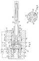
- a roller assembly 10comprises a roller 12 with bearings 14 , 16 , mounting the roller 12 for rotation on a central shaft 18 in a supporting carriage 20 .
- the roller assembly 10is secured to a hollow stem 22 which in turn is supported in spherical joint 24 within a piston 26 positioned within a cylinder 28 .
- the cylinder and pistonbetween themselves define a chamber having two portions 30 a , 30 b .
- Movement of the piston 26is achieved by varying the pressure of hydraulic fluid supplied to each chamber 30 a , 30 b in a manner well known to those skilled the art and therefore not described in detail herein. Cooling fluid is supplied from a source thereof 32 to passage 34 extending along the stem 22 and thence to a pair of outlets 36 before being sprayed onto the surface of roller 12 . Before passing into passageway 34 the lubricating fluid enters a chamber 38 into which the proximal end 40 of the piston/stem assembly 26 , 34 extends. As a consequence of this arrangement, it will be appreciated that lubricating fluid pressure will act against proximal end 40 and this might affect the accurate positioning of the roller assembly 10 .
- a roller control unit for a continuously-variable-ratio transmissioncomprises:
- a lubrication supply passagefor supplying lubrication to a roller connected to said piston for movement therewith; characterised in that said lubrication supply passage comprises a chamber formed between said piston and cylinder wall and one or more radially extending passageways through said piston, each having a first end in fluid communication with said chamber and having a second end in communication with said roller.
- said chambercomprises a recess in the cylinder wall.
- said chambercomprises an annular recess.
- control unitfurther includes seal means in said cylinder wall at each axial end of said chamber and acting between the cylinder wall and said piston.
- the chambermay comprise a recess in the outer surface of the piston.
- the alternative chambermay comprise an annular recess.
- the roller control unitfurther includes seal means at axially displaced positions on the piston and acting between the piston and the cylinder wall.
- the pistoncomprises a hollow piston having a cavity therein in which one or more of the second ends of said one or more passageways are in fluid communication therewith.
- the roller control unitfurther includes a roller support stem having an axially extending lubrication supply duct and in which said duct includes a first end in fluid communication with said cavity for receiving lubrication fluid therefrom.
- the cavitycomprises an open ended cavity having an open end and said unit further includes a plug fixed relative to said cylinder and extending into said open end of said piston, thereby to define said cavity between itself and an end face of said piston.
- said plugis a sliding fit within said cavity and, in operation, said piston slides over said plug thereby to define a cavity of variable volume.
- said chamberis formed at least in part by said plug.
- the chambercomprises two portions, said first portion being bounded by the cylinder and piston and the second portion being bounded by said cylinder, piston and a plug fixed relative to said cylinder and extending into an axially extending cavity within said piston.
- FIG. 1is a cross sectional view of a prior known roller control unit
- FIG. 2is a cross sectional view of a roller control unit in accordance with the present invention.
- FIG. 3is a cross sectional view taken in the direction of arrows 3 — 3 of FIG. 2;
- FIG. 4is a cross-sectional view of an alternative piston arrangement
- FIG. 5is a part cross-sectional view of an alternative passageway arrangement
- FIG. 6is a cross-sectional view taken in the direction of arrows 6 — 6 in FIG. 5;
- FIG. 7is a cross-sectional view of a still further piston arrangement, in which the cross-section of the plug 76 is taken in the direction of arrows 7 — 7 in FIG. 8;
- FIGS. 8 and 9are more detailed views of the plug.
- a roll control unit 50according to the present invention and suitable for use with a continuously-variable-ratio transmission comprises a piston and cylinder arrangement shown generally at 52 .
- the cylinder itself 54comprises an axially extending cylinder wall 56 and end walls 58 , 60 having hydraulic supply ducts 62 , 64 provided therein for supplying hydraulic fluid to chambers 66 , 68 formed between said cylinder 54 and the piston itself 70 .
- the piston 70comprises a two-part piston 70 a , 70 b having a rose bearing or spherical joint 72 sandwiched there between.
- the first portion 70 a of said pistoncomprises a hollow piston portion having a cavity 74 formed therein and which, in operation, receives a plug 76 fixed relative to said cylinder 54 .
- the plug 76extends into an open end of said piston, thereby in combination with said first piston portion to define said cavity 74 .
- a seal 78is provided between the plug 76 and first piston portion 70 a in order to prevent the fluid escaping from said chamber 74 .
- the second portion 70 b of said pistonincludes a recess 80 in which said rose bearing 72 is situated.
- An extension portion 82 of said second piston portion 70 bextends along the said cylinder and co-operates with an outlet 84 in said end wall 58 in order to define an inner boundary for chamber 66 .
- a roller support stem 86extends between the inner portion of said rose bearing 72 and a roller assembly shown generally at 88 in a manner well known in the prior art.
- the stemeffectively comprises a tube having as large an internal diameter d as possible in order to minimise fluid drag there through.
- An outlet end 90 of said stemincludes an outlet 92 which is itself as large as practical.
- the cylinder 54includes a chamber 94 formed at an annular or part annular recess in the wall 56 and is in a fluid flow communication with a large diameter lubrication supply duct 96 for receiving lubrication fluid as and when necessary.
- Seals 98 , 100provided at axially displaced positions within said cylinder wall 56 act to define the outer boundaries of chamber 94 and sealed between said cylinder wall 56 and piston 70 .
- One or more radially extending passageways 102extend through the piston 70 and have a first end 102 a in flow communication with chamber 94 and a second end 102 b in flow communication with said chamber 74 which is in turn in communication with the outlet 92 of roller assembly 88 .
- Operation of the roll assemblyis conventional and requires one simply to vary the pressures within chamber 66 , 68 so as to move the piston 70 and roll assembly 88 to any desired position.
- the source of pressurised hydraulic fluidis provided at 110 and suitable ducting supplies said fluid to inlet 62 , 64 as and when required.
- Supply of cooling fluid to the roller assembly 88is, however, somewhat unconventional and requires the lubrication to be passed from source 110 to chamber 74 via inlet 96 .
- the inletis provided with as large a wall diameter as possible so as to minimise any flow resistance therethrough.
- the capacity of chamber 74will vary in accordance with the piston's position.
- passageways 102are arranged to enter the chamber close to proximal end 112 and between it and an end stop surface 114 provided on first piston portion 70 a . At no time does plug 76 protrude beyond surface 114 and so a minimum chamber volume is maintained at all times.
- the inlet to passageways 102remain within the confines of chamber 94 regardless of the actual position of the position 70 . Consequently, the flow of cooling fluid to the roller remains uninterrupted during piston movement.
- passageways 102could comprise radially extending slots as shown or may comprise simple drillings as well known in the art and therefore not shown or described further herein.
- the advantage of the slotted arrangementresides in the fact that rotation of the roller assembly may be accommodated without interrupting or significantly affecting the supply of cooling fluid to the said roller.
- the chamber 94may be replaced by a chamber 194 provided by forming a recess 116 within the piston assembly itself.
- the ends of said chamberare provided with seals 196 , 198 mounted in the piston body and slidable along the cylinder wall 56 in order to seal said cavity relative to said cylinder.
- Operation of this arrangementis identical to that described above save that lubrication fluid entering chamber 194 will have a pressurising effect P 1 on either end of the piston but, as these forces will balance each other this has no effect on the overall position of the piston itself.
- Advantage of this arrangementresides in the fact that the cylinder wall may comprise a smooth wall arrangement as presently known in the art.
- passageway arrangement 102 and piston assembly 70may be further altered so as to increase the size of the coolant passageways.
- the passagewaysare formed as slots in an end face 74 b if the second portion 74 . These slots are best seen in FIG. 6 and can be formed by making a straight cutting pass which machines two passageways in one pass.
- a further advantageresides in the fact hat such passageways do not taper towards the outlet end 102 b and, hence, a more even flow of fluid is achieved and friction losses reduced.
- FIG. 7A further form of the present invention is shown in FIG. 7 .
- a plug 1100is inserted in the piston such that it creates a chamber 1102 between itself and the end 112 of stem 86 .
- the plugis firmly secured by conventional means to said piston 70 such that it moves therewith as and when the roller position is altered.
- the radially extending passageways 1104supply said chamber 112 with lubrication fluid in the manner already described with reference to the earlier embodiments.
- passageways 1104are shown angled relative to those of the earlier embodiments thereby to ensure the inlet thereto remains within chamber 94 regardless of piston position. It will, however, be appreciated that these passageways maybe provided in the form as shown in FIGS. 2 and 3 so long as passageway 94 is extended to suit.
- the plug 76still extends into opening 74 a in the piston but is now provided with a vent passage 1106 which communications with outlet 1108 which is in turn in direct contact with a sump (not shown) or some other suitable reservoir of fluid at lower pressure.
- the particular example shownis a master cylinder and, consequently, the cross-section includes an outlet passage 64 b from chamber 68 which communicates with similar chambers provided on the slave pistons (not shown). The outlet from chamber 66 is not shown in this drawing.
- FIG. 7 embodimentOperation of the FIG. 7 embodiment is similar to that described above save for the fact that lubrication fluid supplied by inlet 1104 enters chamber 112 and any pressure within the chamber reacts against end face 112 and plug 1100 rather than between end face 112 and plug 76 . Consequently, any pressure which the lubrication fluid might exert on end face 112 and which previously might affect the position of the roller now has an equal and opposite force also acting on a component which is integral with the piston 70 . Consequently, there will be no resultant force which might influence the roller position and this design improves on the above-discussed arrangement. It will be appreciated that the piston 70 will still slide over plug 76 and that a chamber 1110 is created between plug 76 and plug 1100 .
- This chambermust be vented in order to facilitate movement of the plug and this is achieved by passageways 1106 and 1108 mentioned previously. If necessary, an end stop 1112 may be provided on plug 76 so that the axial displacement of piston 70 is controlled within desired limits, thereby to ensure lubrication fluid is always supplied to the roller.
- plug 76includes shield portions 76 a , 76 b which extend downwardly towards outlet 64 b and shields this outlet whenever piston 70 abuts end stop 1112 .
- hydraulic fluidis supplied by inlet 64 and passes between the end of piston 70 and end stop 1112 before passing into the opening 1114 formed between walls 76 a , 76 b and thence into outlet 64 b and on to any slave cylinders.
- This arrangementprovides the piston with an hydraulic end stop due to the pressure the hydraulic fluid exerts on the piston 70 during its translation towards end stop 1112 . Actuation of the master piston 70 and any slave pistons is achieved by simply increasing the pressure at inlet 64 which then moves piston 70 away from inlet 1114 thus allowing the passage of hydraulic fluid to the remaining pistons.
Landscapes
- Engineering & Computer Science (AREA)
- General Engineering & Computer Science (AREA)
- Mechanical Engineering (AREA)
- Friction Gearing (AREA)
- General Details Of Gearings (AREA)
- Control Of Fluid Gearings (AREA)
Abstract
Description
Claims (17)
Applications Claiming Priority (3)
| Application Number | Priority Date | Filing Date | Title |
|---|---|---|---|
| GB9808946 | 1998-04-27 | ||
| GB9808946AGB2336879A (en) | 1998-04-27 | 1998-04-27 | Roller control unit for CVT |
| PCT/GB1999/001273WO1999056036A1 (en) | 1998-04-27 | 1999-04-26 | Cooling fluid supply to hydraulically actuated rollers in a continuously-variable-ratio transmission |
Related Parent Applications (1)
| Application Number | Title | Priority Date | Filing Date |
|---|---|---|---|
| PCT/GB1999/001273ContinuationWO1999056036A1 (en) | 1998-04-27 | 1999-04-26 | Cooling fluid supply to hydraulically actuated rollers in a continuously-variable-ratio transmission |
Publications (1)
| Publication Number | Publication Date |
|---|---|
| US6306060B1true US6306060B1 (en) | 2001-10-23 |
Family
ID=10831038
Family Applications (1)
| Application Number | Title | Priority Date | Filing Date |
|---|---|---|---|
| US09/660,513Expired - LifetimeUS6306060B1 (en) | 1998-04-27 | 2000-09-12 | Cooling fluid supply to hydraulically actuated rollers in a continuously-variable-ratio transmission |
Country Status (8)
| Country | Link |
|---|---|
| US (1) | US6306060B1 (en) |
| EP (1) | EP1073851B1 (en) |
| JP (1) | JP2002513124A (en) |
| KR (1) | KR20010043099A (en) |
| DE (1) | DE69902525T2 (en) |
| ES (1) | ES2178431T3 (en) |
| GB (1) | GB2336879A (en) |
| WO (1) | WO1999056036A1 (en) |
Cited By (15)
| Publication number | Priority date | Publication date | Assignee | Title |
|---|---|---|---|---|
| US20050143216A1 (en)* | 2002-01-24 | 2005-06-30 | Greenwood Christopher J. | Fluid supply arrangement for a rolling-traction continuously variable ratio transmission unit |
| US20070197341A1 (en)* | 2002-09-05 | 2007-08-23 | Fernand Careau | Drive roller control for toric-drive transmission |
| CN101187416B (en)* | 2007-08-28 | 2010-05-26 | 王治龙 | Inverse sliding type stepless speed changer |
| US20110140017A1 (en)* | 2009-12-16 | 2011-06-16 | Long Charles F | Fast Valve Actuation System for An Automatic Transmission |
| US20110144872A1 (en)* | 2009-12-16 | 2011-06-16 | Long Charles F | Variator lockout valve system |
| US20110143882A1 (en)* | 2009-12-16 | 2011-06-16 | Long Charles F | System and Method for Multiplexing Gear Engagement Control and Providing Fault Protection in a Toroidal Traction Drive Automatic Transmission |
| US20110138898A1 (en)* | 2009-12-16 | 2011-06-16 | Long Charles F | Variator fault detection system |
| US20110144870A1 (en)* | 2009-12-16 | 2011-06-16 | Long Charles F | Fail-to-neutral system and method for a toroidal traction drive automatic transmission |
| US20110152031A1 (en)* | 2009-12-16 | 2011-06-23 | Brian Schoolcraft | System and method for controlling endload force of a variator |
| US20130292209A1 (en)* | 2011-01-20 | 2013-11-07 | Zf Friedrichshafen Ag | Arrangement of a transmission and of an attachment module |
| US8721494B2 (en) | 2010-12-15 | 2014-05-13 | Allison Transmission, Inc. | Variator multiplex valve scheme for a torroidal traction drive transmision |
| US8727942B2 (en) | 2010-12-15 | 2014-05-20 | AllisonTransmission, Inc. | Dual pump regulator system for a motor vehicle transmission |
| US8840522B2 (en) | 2010-12-15 | 2014-09-23 | Allison Transmission, Inc. | Variator switching valve scheme for a torroidal traction drive transmision |
| US9228650B2 (en) | 2010-08-16 | 2016-01-05 | Allison Transmission, Inc. | Gear scheme for infinitely variable transmission |
| US10023824B2 (en) | 2013-04-11 | 2018-07-17 | Afton Chemical Corporation | Lubricant composition |
Families Citing this family (3)
| Publication number | Priority date | Publication date | Assignee | Title |
|---|---|---|---|---|
| WO2002044587A1 (en)* | 2000-11-29 | 2002-06-06 | Torotrak (Development) Limited | Roller control unit |
| JP4552555B2 (en)* | 2004-07-30 | 2010-09-29 | 井関農機株式会社 | Tractor transmission |
| JP4517286B2 (en)* | 2004-11-10 | 2010-08-04 | 井関農機株式会社 | Cylinder controlled toroidal transmission |
Citations (6)
| Publication number | Priority date | Publication date | Assignee | Title |
|---|---|---|---|---|
| GB1191214A (en) | 1967-02-14 | 1970-05-13 | Metallurg De Saint Urbain Atel | A device having a friction drive between two surfaces in a liquid |
| US3828618A (en)* | 1971-07-27 | 1974-08-13 | Rotax Ltd | Constant speed hydraulically controlled toric transmission with concentric, two piston valve, governor and constant ratio means |
| GB2282196A (en) | 1992-07-03 | 1995-03-29 | Torotrak Dev Ltd | Continuously-variable-ratio transmission of the toroidal-race rolling-traction type |
| WO1997037156A1 (en) | 1996-04-01 | 1997-10-09 | Torotrak (Development) Limited | Roller assembly |
| US5971886A (en)* | 1996-10-31 | 1999-10-26 | Jatco Corporation | Toroidal-type continuously variable transmission |
| US5989150A (en)* | 1996-10-31 | 1999-11-23 | Jatco Corporation | Full toroidal type continuously variable transmission |
- 1998
- 1998-04-27GBGB9808946Apatent/GB2336879A/ennot_activeWithdrawn
- 1999
- 1999-04-26ESES99919363Tpatent/ES2178431T3/ennot_activeExpired - Lifetime
- 1999-04-26EPEP99919363Apatent/EP1073851B1/ennot_activeExpired - Lifetime
- 1999-04-26JPJP2000546159Apatent/JP2002513124A/enactivePending
- 1999-04-26KRKR1020007011983Apatent/KR20010043099A/ennot_activeAbandoned
- 1999-04-26DEDE69902525Tpatent/DE69902525T2/ennot_activeExpired - Fee Related
- 1999-04-26WOPCT/GB1999/001273patent/WO1999056036A1/enactiveIP Right Grant
- 2000
- 2000-09-12USUS09/660,513patent/US6306060B1/ennot_activeExpired - Lifetime
Patent Citations (8)
| Publication number | Priority date | Publication date | Assignee | Title |
|---|---|---|---|---|
| GB1191214A (en) | 1967-02-14 | 1970-05-13 | Metallurg De Saint Urbain Atel | A device having a friction drive between two surfaces in a liquid |
| US3828618A (en)* | 1971-07-27 | 1974-08-13 | Rotax Ltd | Constant speed hydraulically controlled toric transmission with concentric, two piston valve, governor and constant ratio means |
| GB2282196A (en) | 1992-07-03 | 1995-03-29 | Torotrak Dev Ltd | Continuously-variable-ratio transmission of the toroidal-race rolling-traction type |
| US5564993A (en)* | 1992-07-03 | 1996-10-15 | Torotrak (Development) Limited | Continously-variable-ratio transmission of the toroidal-race rolling-traction type |
| WO1997037156A1 (en) | 1996-04-01 | 1997-10-09 | Torotrak (Development) Limited | Roller assembly |
| US5971885A (en)* | 1996-04-01 | 1999-10-26 | Torotrak (Development) Limited | Roller assembly |
| US5971886A (en)* | 1996-10-31 | 1999-10-26 | Jatco Corporation | Toroidal-type continuously variable transmission |
| US5989150A (en)* | 1996-10-31 | 1999-11-23 | Jatco Corporation | Full toroidal type continuously variable transmission |
Cited By (33)
| Publication number | Priority date | Publication date | Assignee | Title |
|---|---|---|---|---|
| US20050143216A1 (en)* | 2002-01-24 | 2005-06-30 | Greenwood Christopher J. | Fluid supply arrangement for a rolling-traction continuously variable ratio transmission unit |
| US7491149B2 (en)* | 2002-01-24 | 2009-02-17 | Torotrak (Development) Limited | Fluid supply arrangement for a rolling-traction continuously variable ratio transmission unit |
| US20070197341A1 (en)* | 2002-09-05 | 2007-08-23 | Fernand Careau | Drive roller control for toric-drive transmission |
| CN101187416B (en)* | 2007-08-28 | 2010-05-26 | 王治龙 | Inverse sliding type stepless speed changer |
| US8744697B2 (en) | 2009-12-16 | 2014-06-03 | Allison Transmission, Inc. | Variator lockout valve system |
| US8578802B2 (en) | 2009-12-16 | 2013-11-12 | Allison Transmission, Inc. | System and method for multiplexing gear engagement control and providing fault protection in a toroidal traction drive automatic transmission |
| US20110143882A1 (en)* | 2009-12-16 | 2011-06-16 | Long Charles F | System and Method for Multiplexing Gear Engagement Control and Providing Fault Protection in a Toroidal Traction Drive Automatic Transmission |
| US20110138898A1 (en)* | 2009-12-16 | 2011-06-16 | Long Charles F | Variator fault detection system |
| US20110144870A1 (en)* | 2009-12-16 | 2011-06-16 | Long Charles F | Fail-to-neutral system and method for a toroidal traction drive automatic transmission |
| US20110152031A1 (en)* | 2009-12-16 | 2011-06-23 | Brian Schoolcraft | System and method for controlling endload force of a variator |
| US8401752B2 (en) | 2009-12-16 | 2013-03-19 | Allison Transmission, Inc. | Fail-to-neutral system and method for a toroidal traction drive automatic transmission |
| US8424373B2 (en) | 2009-12-16 | 2013-04-23 | Allison Transmission, Inc. | Variator fault detection system |
| US9347555B2 (en) | 2009-12-16 | 2016-05-24 | Allison Transmission, Inc. | Variator lockout valve system |
| US9267582B2 (en) | 2009-12-16 | 2016-02-23 | Allison Transmission, Inc. | System and method for multiplexing gear engagement control and providing fault protection in a toroidal traction drive automatic transmission |
| US10253875B2 (en) | 2009-12-16 | 2019-04-09 | Allison Transmission, Inc. | System and method for multiplexing gear engagement control and providing fault protection in a toroidal traction drive automatic transmission |
| US9784366B2 (en) | 2009-12-16 | 2017-10-10 | Allison Transmission, Inc. | Fast valve actuation system for an automatic transmission |
| US20110140017A1 (en)* | 2009-12-16 | 2011-06-16 | Long Charles F | Fast Valve Actuation System for An Automatic Transmission |
| US8770018B2 (en) | 2009-12-16 | 2014-07-08 | Allison Transmission, Inc. | Variator fault detection system |
| US8821340B2 (en) | 2009-12-16 | 2014-09-02 | Allison Transmission, Inc. | System and method for controlling endload force of a variator |
| US20110144872A1 (en)* | 2009-12-16 | 2011-06-16 | Long Charles F | Variator lockout valve system |
| US8852049B2 (en) | 2009-12-16 | 2014-10-07 | Allison Transmission, Inc. | Fast valve actuation system for an automatic transmission |
| US9103434B2 (en) | 2009-12-16 | 2015-08-11 | Allison Transmission, Inc. | Fail-to-neutral system and method for a toroidal traction drive automatic transmission |
| US10253859B2 (en) | 2010-08-16 | 2019-04-09 | Allison Transmission, Inc. | Gear scheme for infinitely variable transmission |
| US9228650B2 (en) | 2010-08-16 | 2016-01-05 | Allison Transmission, Inc. | Gear scheme for infinitely variable transmission |
| US9534672B2 (en) | 2010-12-15 | 2017-01-03 | Allison Transmission, Inc. | Variator switching valve scheme for a torroidal traction drive transmission |
| US8840522B2 (en) | 2010-12-15 | 2014-09-23 | Allison Transmission, Inc. | Variator switching valve scheme for a torroidal traction drive transmision |
| US9541191B2 (en) | 2010-12-15 | 2017-01-10 | Allison Transmission, Inc. | Dual pump regulator system for a motor vehicle transmission |
| US9562594B2 (en) | 2010-12-15 | 2017-02-07 | Allison Transmission, Inc. | Variator multiplex valve scheme for a torroidal traction drive transmission |
| US8727942B2 (en) | 2010-12-15 | 2014-05-20 | AllisonTransmission, Inc. | Dual pump regulator system for a motor vehicle transmission |
| US8721494B2 (en) | 2010-12-15 | 2014-05-13 | Allison Transmission, Inc. | Variator multiplex valve scheme for a torroidal traction drive transmision |
| US9212735B2 (en)* | 2011-01-20 | 2015-12-15 | Zf Friedrichshafen | Arrangement of a transmission and of an attachment module |
| US20130292209A1 (en)* | 2011-01-20 | 2013-11-07 | Zf Friedrichshafen Ag | Arrangement of a transmission and of an attachment module |
| US10023824B2 (en) | 2013-04-11 | 2018-07-17 | Afton Chemical Corporation | Lubricant composition |
Also Published As
| Publication number | Publication date |
|---|---|
| KR20010043099A (en) | 2001-05-25 |
| GB2336879A (en) | 1999-11-03 |
| ES2178431T3 (en) | 2002-12-16 |
| EP1073851A1 (en) | 2001-02-07 |
| GB9808946D0 (en) | 1998-06-24 |
| WO1999056036A1 (en) | 1999-11-04 |
| EP1073851B1 (en) | 2002-08-14 |
| DE69902525T2 (en) | 2003-04-24 |
| JP2002513124A (en) | 2002-05-08 |
| DE69902525D1 (en) | 2002-09-19 |
Similar Documents
| Publication | Publication Date | Title |
|---|---|---|
| US6306060B1 (en) | Cooling fluid supply to hydraulically actuated rollers in a continuously-variable-ratio transmission | |
| US3943803A (en) | Mounting arrangement for a spindle | |
| KR100387159B1 (en) | Thrust Bearing Arrangement for Turbocharger | |
| EP0930449B1 (en) | Roller assembly for piston actuator | |
| US5746676A (en) | Friction type continuously variable transmission | |
| CA2062386C (en) | Roll for use in calenders and like machines | |
| AU649694B2 (en) | Self-loading controlled deflection roll | |
| US5080401A (en) | Rotary coupling for fluid between stationary and rotating machine parts | |
| US4522110A (en) | Hydraulic radial piston motor | |
| JPH11510588A (en) | High pressure and high speed rotary transmission readthrough | |
| US6273839B1 (en) | Roller control unit for a continuously-variable-ratio transmission | |
| US4586539A (en) | Flow adjusting valve and die casting machine incorporating the same | |
| CA1317896C (en) | Lubrication system for a transmission mechanism | |
| US5189776A (en) | Roller | |
| US4241482A (en) | Deflection compensating roll | |
| JPS63221902A (en) | Hydraulic operation type cylinder for fixing device in rotational spindle | |
| CA1307967C (en) | Press rolls | |
| CA1045173A (en) | Non-friction pressure seal | |
| US4464136A (en) | Lubricated wide angle universal joint | |
| WO2002004827A1 (en) | A hydrostatic bearing for use in a turbocharger | |
| US7261183B2 (en) | Lube oil distribution apparatus | |
| EP0733165B1 (en) | Radial journal bearing with slide shoe, and slide shoe for a radial journal bearing | |
| JPH0541879B2 (en) | ||
| US6120186A (en) | Lighter bearing assembly | |
| US6705978B2 (en) | Structure between driving transmission and roll |
Legal Events
| Date | Code | Title | Description |
|---|---|---|---|
| AS | Assignment | Owner name:TOROTRAK (DEVELOPMENT) LIMITED, UNITED KINGDOM Free format text:ASSIGNMENT OF ASSIGNORS INTEREST;ASSIGNORS:DUTSON, BRIAN J.;DE FREITAS, ANDREW D.;REEL/FRAME:011095/0568 Effective date:20000818 | |
| STCF | Information on status: patent grant | Free format text:PATENTED CASE | |
| FPAY | Fee payment | Year of fee payment:4 | |
| FPAY | Fee payment | Year of fee payment:8 | |
| FEPP | Fee payment procedure | Free format text:PAYOR NUMBER ASSIGNED (ORIGINAL EVENT CODE: ASPN); ENTITY STATUS OF PATENT OWNER: LARGE ENTITY | |
| FPAY | Fee payment | Year of fee payment:12 | |
| AS | Assignment | Owner name:ALLISON TRANSMISSION, INC., INDIANA Free format text:ASSIGNMENT OF ASSIGNORS INTEREST;ASSIGNOR:TOROTRAK (DEVELOPMENT) LIMITED;REEL/FRAME:046112/0801 Effective date:20180327 | |
| AS | Assignment | Owner name:ALLISON TRANSMISSION, INC., INDIANA Free format text:ASSIGNMENT OF ASSIGNORS INTEREST;ASSIGNOR:TOROTRAK (DEVELOPMENT) LIMITED;REEL/FRAME:046299/0787 Effective date:20180327 |