US6306056B1 - Dual engine hybrid electric vehicle - Google Patents
Dual engine hybrid electric vehicleDownload PDFInfo
- Publication number
- US6306056B1 US6306056B1US09/466,148US46614899AUS6306056B1US 6306056 B1US6306056 B1US 6306056B1US 46614899 AUS46614899 AUS 46614899AUS 6306056 B1US6306056 B1US 6306056B1
- Authority
- US
- United States
- Prior art keywords
- torque
- engine
- motor
- generator
- heat engine
- Prior art date
- Legal status (The legal status is an assumption and is not a legal conclusion. Google has not performed a legal analysis and makes no representation as to the accuracy of the status listed.)
- Expired - Lifetime
Links
Images


Classifications
- B—PERFORMING OPERATIONS; TRANSPORTING
- B60—VEHICLES IN GENERAL
- B60W—CONJOINT CONTROL OF VEHICLE SUB-UNITS OF DIFFERENT TYPE OR DIFFERENT FUNCTION; CONTROL SYSTEMS SPECIALLY ADAPTED FOR HYBRID VEHICLES; ROAD VEHICLE DRIVE CONTROL SYSTEMS FOR PURPOSES NOT RELATED TO THE CONTROL OF A PARTICULAR SUB-UNIT
- B60W20/00—Control systems specially adapted for hybrid vehicles
- B60W20/10—Controlling the power contribution of each of the prime movers to meet required power demand
- B—PERFORMING OPERATIONS; TRANSPORTING
- B60—VEHICLES IN GENERAL
- B60K—ARRANGEMENT OR MOUNTING OF PROPULSION UNITS OR OF TRANSMISSIONS IN VEHICLES; ARRANGEMENT OR MOUNTING OF PLURAL DIVERSE PRIME-MOVERS IN VEHICLES; AUXILIARY DRIVES FOR VEHICLES; INSTRUMENTATION OR DASHBOARDS FOR VEHICLES; ARRANGEMENTS IN CONNECTION WITH COOLING, AIR INTAKE, GAS EXHAUST OR FUEL SUPPLY OF PROPULSION UNITS IN VEHICLES
- B60K5/00—Arrangement or mounting of internal-combustion or jet-propulsion units
- B60K5/08—Arrangement or mounting of internal-combustion or jet-propulsion units comprising more than one engine
- B—PERFORMING OPERATIONS; TRANSPORTING
- B60—VEHICLES IN GENERAL
- B60K—ARRANGEMENT OR MOUNTING OF PROPULSION UNITS OR OF TRANSMISSIONS IN VEHICLES; ARRANGEMENT OR MOUNTING OF PLURAL DIVERSE PRIME-MOVERS IN VEHICLES; AUXILIARY DRIVES FOR VEHICLES; INSTRUMENTATION OR DASHBOARDS FOR VEHICLES; ARRANGEMENTS IN CONNECTION WITH COOLING, AIR INTAKE, GAS EXHAUST OR FUEL SUPPLY OF PROPULSION UNITS IN VEHICLES
- B60K6/00—Arrangement or mounting of plural diverse prime-movers for mutual or common propulsion, e.g. hybrid propulsion systems comprising electric motors and internal combustion engines
- B60K6/20—Arrangement or mounting of plural diverse prime-movers for mutual or common propulsion, e.g. hybrid propulsion systems comprising electric motors and internal combustion engines the prime-movers consisting of electric motors and internal combustion engines, e.g. HEVs
- B60K6/42—Arrangement or mounting of plural diverse prime-movers for mutual or common propulsion, e.g. hybrid propulsion systems comprising electric motors and internal combustion engines the prime-movers consisting of electric motors and internal combustion engines, e.g. HEVs characterised by the architecture of the hybrid electric vehicle
- B60K6/48—Parallel type
- B—PERFORMING OPERATIONS; TRANSPORTING
- B60—VEHICLES IN GENERAL
- B60K—ARRANGEMENT OR MOUNTING OF PROPULSION UNITS OR OF TRANSMISSIONS IN VEHICLES; ARRANGEMENT OR MOUNTING OF PLURAL DIVERSE PRIME-MOVERS IN VEHICLES; AUXILIARY DRIVES FOR VEHICLES; INSTRUMENTATION OR DASHBOARDS FOR VEHICLES; ARRANGEMENTS IN CONNECTION WITH COOLING, AIR INTAKE, GAS EXHAUST OR FUEL SUPPLY OF PROPULSION UNITS IN VEHICLES
- B60K6/00—Arrangement or mounting of plural diverse prime-movers for mutual or common propulsion, e.g. hybrid propulsion systems comprising electric motors and internal combustion engines
- B60K6/20—Arrangement or mounting of plural diverse prime-movers for mutual or common propulsion, e.g. hybrid propulsion systems comprising electric motors and internal combustion engines the prime-movers consisting of electric motors and internal combustion engines, e.g. HEVs
- B60K6/50—Architecture of the driveline characterised by arrangement or kind of transmission units
- B60K6/52—Driving a plurality of drive axles, e.g. four-wheel drive
- B—PERFORMING OPERATIONS; TRANSPORTING
- B60—VEHICLES IN GENERAL
- B60W—CONJOINT CONTROL OF VEHICLE SUB-UNITS OF DIFFERENT TYPE OR DIFFERENT FUNCTION; CONTROL SYSTEMS SPECIALLY ADAPTED FOR HYBRID VEHICLES; ROAD VEHICLE DRIVE CONTROL SYSTEMS FOR PURPOSES NOT RELATED TO THE CONTROL OF A PARTICULAR SUB-UNIT
- B60W10/00—Conjoint control of vehicle sub-units of different type or different function
- B60W10/02—Conjoint control of vehicle sub-units of different type or different function including control of driveline clutches
- B—PERFORMING OPERATIONS; TRANSPORTING
- B60—VEHICLES IN GENERAL
- B60W—CONJOINT CONTROL OF VEHICLE SUB-UNITS OF DIFFERENT TYPE OR DIFFERENT FUNCTION; CONTROL SYSTEMS SPECIALLY ADAPTED FOR HYBRID VEHICLES; ROAD VEHICLE DRIVE CONTROL SYSTEMS FOR PURPOSES NOT RELATED TO THE CONTROL OF A PARTICULAR SUB-UNIT
- B60W10/00—Conjoint control of vehicle sub-units of different type or different function
- B60W10/04—Conjoint control of vehicle sub-units of different type or different function including control of propulsion units
- B60W10/06—Conjoint control of vehicle sub-units of different type or different function including control of propulsion units including control of combustion engines
- B—PERFORMING OPERATIONS; TRANSPORTING
- B60—VEHICLES IN GENERAL
- B60W—CONJOINT CONTROL OF VEHICLE SUB-UNITS OF DIFFERENT TYPE OR DIFFERENT FUNCTION; CONTROL SYSTEMS SPECIALLY ADAPTED FOR HYBRID VEHICLES; ROAD VEHICLE DRIVE CONTROL SYSTEMS FOR PURPOSES NOT RELATED TO THE CONTROL OF A PARTICULAR SUB-UNIT
- B60W10/00—Conjoint control of vehicle sub-units of different type or different function
- B60W10/04—Conjoint control of vehicle sub-units of different type or different function including control of propulsion units
- B60W10/08—Conjoint control of vehicle sub-units of different type or different function including control of propulsion units including control of electric propulsion units, e.g. motors or generators
- B—PERFORMING OPERATIONS; TRANSPORTING
- B60—VEHICLES IN GENERAL
- B60W—CONJOINT CONTROL OF VEHICLE SUB-UNITS OF DIFFERENT TYPE OR DIFFERENT FUNCTION; CONTROL SYSTEMS SPECIALLY ADAPTED FOR HYBRID VEHICLES; ROAD VEHICLE DRIVE CONTROL SYSTEMS FOR PURPOSES NOT RELATED TO THE CONTROL OF A PARTICULAR SUB-UNIT
- B60W20/00—Control systems specially adapted for hybrid vehicles
- F—MECHANICAL ENGINEERING; LIGHTING; HEATING; WEAPONS; BLASTING
- F02—COMBUSTION ENGINES; HOT-GAS OR COMBUSTION-PRODUCT ENGINE PLANTS
- F02B—INTERNAL-COMBUSTION PISTON ENGINES; COMBUSTION ENGINES IN GENERAL
- F02B73/00—Combinations of two or more engines, not otherwise provided for
- Y—GENERAL TAGGING OF NEW TECHNOLOGICAL DEVELOPMENTS; GENERAL TAGGING OF CROSS-SECTIONAL TECHNOLOGIES SPANNING OVER SEVERAL SECTIONS OF THE IPC; TECHNICAL SUBJECTS COVERED BY FORMER USPC CROSS-REFERENCE ART COLLECTIONS [XRACs] AND DIGESTS
- Y02—TECHNOLOGIES OR APPLICATIONS FOR MITIGATION OR ADAPTATION AGAINST CLIMATE CHANGE
- Y02T—CLIMATE CHANGE MITIGATION TECHNOLOGIES RELATED TO TRANSPORTATION
- Y02T10/00—Road transport of goods or passengers
- Y02T10/60—Other road transportation technologies with climate change mitigation effect
- Y02T10/62—Hybrid vehicles
- Y—GENERAL TAGGING OF NEW TECHNOLOGICAL DEVELOPMENTS; GENERAL TAGGING OF CROSS-SECTIONAL TECHNOLOGIES SPANNING OVER SEVERAL SECTIONS OF THE IPC; TECHNICAL SUBJECTS COVERED BY FORMER USPC CROSS-REFERENCE ART COLLECTIONS [XRACs] AND DIGESTS
- Y10—TECHNICAL SUBJECTS COVERED BY FORMER USPC
- Y10S—TECHNICAL SUBJECTS COVERED BY FORMER USPC CROSS-REFERENCE ART COLLECTIONS [XRACs] AND DIGESTS
- Y10S903/00—Hybrid electric vehicles, HEVS
- Y10S903/902—Prime movers comprising electrical and internal combustion motors
- Y10S903/903—Prime movers comprising electrical and internal combustion motors having energy storing means, e.g. battery, capacitor
- Y10S903/904—Component specially adapted for hev
- Y10S903/915—Specific drive or transmission adapted for hev
- Y10S903/916—Specific drive or transmission adapted for hev with plurality of drive axles
- Y—GENERAL TAGGING OF NEW TECHNOLOGICAL DEVELOPMENTS; GENERAL TAGGING OF CROSS-SECTIONAL TECHNOLOGIES SPANNING OVER SEVERAL SECTIONS OF THE IPC; TECHNICAL SUBJECTS COVERED BY FORMER USPC CROSS-REFERENCE ART COLLECTIONS [XRACs] AND DIGESTS
- Y10—TECHNICAL SUBJECTS COVERED BY FORMER USPC
- Y10S—TECHNICAL SUBJECTS COVERED BY FORMER USPC CROSS-REFERENCE ART COLLECTIONS [XRACs] AND DIGESTS
- Y10S903/00—Hybrid electric vehicles, HEVS
- Y10S903/902—Prime movers comprising electrical and internal combustion motors
- Y10S903/903—Prime movers comprising electrical and internal combustion motors having energy storing means, e.g. battery, capacitor
- Y10S903/946—Characterized by control of driveline clutch
Definitions
- the present inventionrelates generally to hybrid automotive vehicles, and more particularly to a dual engine hybrid electric vehicle.
- Hybrid vehiclesemploying internal combustion engines and electric motors to drive the vehicle are well known in the art.
- Previous hybrid electric vehicle designshave utilized an internal combustion engine which is strategically operated in combination with an electric motor in order to provide driving torque to the wheels of the vehicle.
- the dual engine hybrid electric vehicle of the present inventionovercomes these deficiencies by providing a hybrid electric power train system which includes dual engines, or alternatively, a dual crankshaft system independently operable for providing driving torque to a transmission.
- An electric motor/generatoris also utilized for providing driving torque to the wheels of the vehicle.
- the term “electric motor/generator”is also intended to include a motor/alternator. Operation of the first and second engines such that during normal driving at constant speeds and typical driving load, a single engine is utilized for providing driving torque to the wheels of the vehicle.
- the electric motoris operated temporarily while the second engine is started and brought up to speed to assist the first engine in providing driving torque to the driving wheels of the vehicle.
- the hybrid electric powertrain system of the present inventionincludes a first heat engine, a second heat engine, a torque transmission device operatively engagable with the first and second heat engines and adapted to selectively transfer torque from the first and second heat engines to a pair of driving wheels of the vehicle.
- An electric motor/generatoris provided for delivering driving torque to at least one pair of driving wheels of the motor vehicle.
- a first clutch elementis provided for transmitting torque from the first engine to a transmission gear train and a second clutch is provided for delivering torque from the second engine to the transmission geartrain.
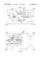
- FIG. 1is a schematic diagram of a dual engine hybrid electric vehicle according to the principles of the present invention
- FIG. 2is an alternative embodiment of the dual engine hybrid electric vehicle according to the principles of the present invention.
- FIG. 3is a schematic diagram of a third embodiment of the hybrid electric vehicle according to the present invention with single engine block and having dual crankshafts separately drivable for providing driving torque to the transmission of a hybrid electric vehicle according to the principles of the present invention;
- FIG. 4is a schematic diagram of the layout of the dual crankshaft system of the engine shown in FIG. 3;
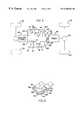
- FIG. 5is a detailed cross-sectional view illustrating the layout of the dual crankshaft internal combustion shown in FIGS. 3 and 4;
- FIG. 6is a diagram of a control system of the dual engine hybrid electric powertrain according to the principles of the present invention.
- a motor vehicle 10including a dual engine hybrid electric powertrain system.
- the hybrid electric powertrain systemincludes a first engine 12 which delivers driving torque to a transmission 14 through a first clutch device 16 .
- a second engine 18is also adapted to provide driving torque to the transmission 14 via a clutch 20 .
- the first engine 12 and second engine 18provide driving torque to a pair of driving wheels 22 through the transmission 14 via a differential 24 .
- An electric motor/generator 28is adapted to provide driving torque to a second pair of driving wheels 30 via a differential 32 .
- the first output shaft of the engine 12 and second engine 18are each provided with a flywheel 34 , 36 , respectively.
- a gear 38is attached to the output shaft of the first engine 12 and meshingly engages a driven gear 40 .
- a second drive gear 42is operatively engaged with the output shaft of the second engine 18 via the clutch 20 .
- the second drive gear 42also engages the driven gear 40 .
- Torqueis transmitted from the driven gear 40 via clutch 16 to the transmission 14 .
- the hybrid electric powertrain system 110includes a first engine 112 and a second engine 118 .
- Each engine 112 , 118is provided with a flywheel 134 , 136 .
- the first engine 112transmits torque to a transmission device 114 via a first clutch device 116 .
- the second engine 118transmits driving torque to the transmission 114 via a second clutch 120 .
- the first and second clutch devices 116 , 120when engaged, deliver torque to a drive sprocket 122 which transmits torque to a driven sprocket 124 via a chain 126 .
- An electric motor/generator 128is operatively engaged with the transmission 114 for providing driving torque thereto.
- the dual engine systemis shown embodied in a single engine block 40 including dual crankshafts.
- the dual crankshaft engine 40includes a first crankshaft 42 and a second crankshaft 44 .
- a plurality of pistons 46are connected to the crankshafts 42 , 44 via connecting pins 48 .
- the pistons 46are disposed within cylinders 50 as is known in the art.
- each crankshaft 42 , 44is associated with two pistons disposed in two corresponding cylinders 50 .
- any number of pistons 46can be utilized according to the principles of the present invention.
- each crankshaft 42 , 44has a flywheel 52 , 54 , respectively.
- a first clutch 16is provided for delivering torque from the first crankshaft 42 to the transmission 14 .
- a second clutch 20is provided for delivering driving torque from the second crankshaft 44 to the transmission device 14 .
- the first crankshaft 42is provided with a driving gear 38 which engages a driven gear 40 .
- the driven gear 40transmits torque to the transmission 14 via clutch 16 .
- a second driving gear 43is provided for delivering torque from the second crankshaft 44 to the driven gear 40 via the second clutch 20 .
- FIG. 5a cross-sectional view of the dual crankshaft engine 40 of the present invention is provided.
- the left primary crankshaft 42has associated with it a plurality of pistons 46 each connected to the crankshaft 42 via connecting rods 48 .
- a valve train system 58is provided including a camshaft 60 and rocker assemblies 62 .
- the right (secondary) crankshaft 44is also provided with a plurality of pistons 46 connected to the crankshaft 44 via connecting rods 48 .
- the pistons 46 and connecting rods 48 of each crankshaft 42 , 44are staggered in a longitudinal direction of the engine so that the crankshafts can be packaged more closely together without interfering with one another.
- a second valve train system 58 ′is provided including a second camshaft 60 ′ and rocker assemblies 62 ′.
- the left and right crankshaft systemsare separately operable but share several common elements.
- the common elementspreferably include a single oil pump, water pump, cooling system, lubrication system, air filter, fuel system, engine block, exhaust system, and oil pan.
- the primary engine systempowers the accessories and heats the catalyst.
- the dual engine hybrid electric powertrain system controller 70provides output signals to the first engine system 72 and second engine system 74 .
- the first and second engine systems 72 , 74are meant to include separate engines as disclosed in the embodiments of FIGS. 1 and 2 but is also intended to include each crankshaft system 42 , 44 of a dual crankshaft engine which is housed in a common engine block, but separately controlled according to the principles described herein.
- the controller 70also provides control signals to the transmission or transmission control unit 76 , the motor/generator 28 , and to first and second clutch actuators 78 , 80 .
- the controller 70receives signals indicating the accelerator position, the brake pedal position, gear position, vehicle speed, battery charge level, the speed of the first engine system (rpm 1), and the speed of the second engine system (rpm 2).
- the first engine system 72is running and the controller 70 provides signals to the first engine system 72 in order to meet the driving demands of the operator based upon the accelerator position and vehicle speed.
- the controller 70also controls the transmission 14 according to well-known shift schedule parameters.
- the controller 70Upon detection of a torque requirement greater than can be supplied by the first engine system 72 , the controller 70 provides a signal to the motor/generator 28 to provide the added necessary torque to supplement the first engine system 72 in order to meet the operator's driving needs.
- the operation of the motor/generatorcan be temporary while the second engine system 74 is turned on and brought up to speed in order to meet the added driving torque requirements of the vehicle operator while the motor/generator 28 is then turned off.
- the electric motoris capable of being run at approximately 150 percent of its rated power for a short duration.
- the controller 70can operate the electric motor at 150 percent of its peak rated power for a period of up to approximately two seconds while the second engine system 74 comes on.
- the systemhas a total of 300 hp capability.
- the electric motorcan be operated at 150 percent of its rated capacity to provide up to 220 hp (115 hp first engine+105 hp motor) for a short duration while the second engine system 74 is started up.
- the rated capacity of the electric motoris provided in part to prevent overheating of the electric motor.
- the electric motorcan be operated safely at a higher capacity for a short time period.
- the motor/generatorcan also be used in combination with both the first and second engine systems 72 , 74 during wide open throttle or at other times when the torque requirement exceeds the amount that can be supplied by the first and second engine systems 72 , 74 combined. In the above example, a total of 300 hp can be achieved.
- the controllerdetermines a torque demand T d based upon the accelerator position and vehicle speed. It will then be determined whether the torque demand T d is greater than the torque available from the first engine T al . If the torque demand does not exceed the amount of torque available from the first engine T al , then the first engine continues to be controlled according to normal operating parameters which are well known in the art. If the torque demand exceeds the torque available from the first engine (T d >T al ), it is then determined if the second engine system is ready to provide the additional torque necessary to meet the torque demand T d . If the second engine system is not ready, the motor/generator is then operated to provide a motor torque T m equal to the difference between the torque demand T d and the torque available from the first engine T al .
- the motor ( 28 , 128 )is operated at a level exceeding its normal power rating with the controller imposing a time limit for operation of the motor ( 28 , 128 ) at this higher capacity in order to prevent overheating.
- the time limitcan be a predetermined time period or can be obtained from a look-up table which includes the time limits based upon ambient temperature.
- the second engine system 74is started up and is brought up to speed to provide the added required torque T a2 which is equal to the difference between the torque demand and the torque available from the first engine system (T d ⁇ T al ).
- the second clutchis engaged in order to provide driving torque from the second engine system 74 to the transmission 14 .
- the torque generated by the motor/generator ( 28 , 128 )is decreased in order to provide a smooth transition from the motor ( 28 , 128 ) to the second engine system 74 for providing the necessary torque to equal the amount of torque demand T d .
Landscapes
- Engineering & Computer Science (AREA)
- Chemical & Material Sciences (AREA)
- Combustion & Propulsion (AREA)
- Mechanical Engineering (AREA)
- Transportation (AREA)
- General Engineering & Computer Science (AREA)
- Automation & Control Theory (AREA)
- Control Of Vehicle Engines Or Engines For Specific Uses (AREA)
- Hybrid Electric Vehicles (AREA)
Abstract
Description
Claims (11)
Priority Applications (1)
| Application Number | Priority Date | Filing Date | Title |
|---|---|---|---|
| US09/466,148US6306056B1 (en) | 1999-12-17 | 1999-12-17 | Dual engine hybrid electric vehicle |
Applications Claiming Priority (1)
| Application Number | Priority Date | Filing Date | Title |
|---|---|---|---|
| US09/466,148US6306056B1 (en) | 1999-12-17 | 1999-12-17 | Dual engine hybrid electric vehicle |
Publications (1)
| Publication Number | Publication Date |
|---|---|
| US6306056B1true US6306056B1 (en) | 2001-10-23 |
Family
ID=23850691
Family Applications (1)
| Application Number | Title | Priority Date | Filing Date |
|---|---|---|---|
| US09/466,148Expired - LifetimeUS6306056B1 (en) | 1999-12-17 | 1999-12-17 | Dual engine hybrid electric vehicle |
Country Status (1)
| Country | Link |
|---|---|
| US (1) | US6306056B1 (en) |
Cited By (70)
| Publication number | Priority date | Publication date | Assignee | Title |
|---|---|---|---|---|
| US20020074177A1 (en)* | 1999-02-24 | 2002-06-20 | Paolo Pasquini | Power plant for electric earth-moving and agricultural vehicles with four-wheel drive |
| US6540642B2 (en)* | 1999-12-02 | 2003-04-01 | Toyota Jidosha Kabushiki Kaisha | Vehicle control system and vehicle control method |
| US20040045287A1 (en)* | 2002-09-11 | 2004-03-11 | Wylin James P. | Fluid lock double displacement engine |
| US6722458B2 (en)* | 2001-08-27 | 2004-04-20 | Fev Motorentechnik Gmbh | Multi-engine drive system for a vehicle |
| US20040172946A1 (en)* | 2003-03-05 | 2004-09-09 | Gray Charles L. | Multi-crankshaft, variable-displacement engine |
| US20040195016A1 (en)* | 2003-04-04 | 2004-10-07 | Hitachi, Ltd. | Vehicle drive train unit and vehicle drive train system |
| US6814686B2 (en) | 2003-01-09 | 2004-11-09 | Daimlerchrysler Corporation | Dual engine crankshaft coupling arrangement |
| US6830532B1 (en) | 2003-07-30 | 2004-12-14 | Daimlerchrysler Corporation | Method for controlling a powertrain having multiple torque sources |
| US20050023058A1 (en)* | 2003-07-30 | 2005-02-03 | Gebby Brian P. | Method for providing acceleration in a multiple torque source powertrain to simulate a single torque source powertrain |
| US6852062B1 (en)* | 1999-07-27 | 2005-02-08 | Robert Bosch Gmbh | Drive system for motor vehicles |
| US20050049108A1 (en)* | 2003-08-04 | 2005-03-03 | Kabushiki Kaisha Toyota Chuo Kenkyusho | Engine system with cylinder number variable engine and method for controlling the engine system |
| US6878092B1 (en)* | 1999-02-01 | 2005-04-12 | Robert Bosch Gmbh | Drive arrangement for at least one secondary aggregate of a motor vehicle and method for operating the drive arrangement |
| US20050109549A1 (en)* | 2003-11-26 | 2005-05-26 | Oshkosh Truck Corporation | Power splitting vehicle drive system |
| US20050126173A1 (en)* | 2003-12-03 | 2005-06-16 | Anderson Donald D. | Controlling airflow to multiple engine modules with a single throttle body |
| WO2005075235A1 (en)* | 2004-02-06 | 2005-08-18 | Jansson Sven A | Enging unit for hybrid vehicles |
| US20050179262A1 (en)* | 2004-02-18 | 2005-08-18 | Wavecrest Laboratories, Llc | Portable range extender with autonomous control of starting and stopping operations |
| US20050279542A1 (en)* | 2004-06-22 | 2005-12-22 | Maslov Boris A | Autonomous portable range extender |
| US20060011395A1 (en)* | 2004-05-20 | 2006-01-19 | Toyota Jidosha Kabushiki Kaisha | Hybrid drive unit for vehicles |
| US7152705B2 (en)* | 2003-12-23 | 2006-12-26 | Caterpillar Inc | Dual engine electric drive system |
| US20070012493A1 (en)* | 2005-06-21 | 2007-01-18 | Jones Steven M | Dual hybrid propulsion system |
| WO2006117617A3 (en)* | 2005-04-29 | 2007-03-22 | Prototipo S P A | Engine unit with start-stop control for a motor vehicle |
| US20070142166A1 (en)* | 2005-12-15 | 2007-06-21 | Gebby Brian P | Control of a vehicle powertrain with multiple prime movers |
| US20070151783A1 (en)* | 2004-03-31 | 2007-07-05 | Tomokazu Yamauchi | Power output apparatus and motor vehicle equipped with power output apparatus |
| FR2895941A1 (en)* | 2006-01-12 | 2007-07-13 | Renault Sas | Bi-engine propulsion system for high performance motor vehicle e.g. car, has booster and urban engines comprising booster and urban clutches selectively actuated by control and command unit for controlling linking of engines to gearbox |
| US20070191179A1 (en)* | 2006-02-13 | 2007-08-16 | Ludger Hugenroth | Motor vehicle |
| DE10231006B4 (en)* | 2002-07-09 | 2007-10-31 | Amovis Gmbh | Apparatus for generating mechanical work using expansion engines |
| US7325638B1 (en)* | 2005-11-21 | 2008-02-05 | Belloso Gregorio M | Motor vehicle with a primary engine for acceleration and secondary engine augmented by an electric motor for cruising |
| WO2008064881A1 (en) | 2006-11-29 | 2008-06-05 | Airbus Deutschland Gmbh | Propulsion device for operation with a plurality of fuels for an aircraft |
| WO2008065065A1 (en)* | 2006-11-29 | 2008-06-05 | Airbus Deutschland Gmbh | Propulsion device with a plurality of energy converters for an aircraft |
| US7410021B1 (en)* | 2005-09-19 | 2008-08-12 | Belloso Gregorio M | Fuel-efficient vehicle with auxiliary cruiser engine |
| WO2008076694A3 (en)* | 2006-12-14 | 2008-08-21 | Kevin R Williams | Flywheel system for use with motorized wheels in a hybrid vehicle |
| WO2008107061A1 (en)* | 2007-03-03 | 2008-09-12 | Bayerische Motoren Werke Aktiengesellschaft | Hybrid vehicle having a split motor |
| US7468562B1 (en)* | 2006-12-25 | 2008-12-23 | Mato Barbic | Intermittant electrical charging AC/DC driving system |
| US20090288899A1 (en)* | 2008-05-20 | 2009-11-26 | Belloso Gregorio M | Vehicle with multiple engines coupled to a transmission via a jackshaft |
| US7635932B2 (en) | 2004-08-18 | 2009-12-22 | Bluwav Systems, Llc | Dynamoelectric machine having heat pipes embedded in stator core |
| US20100005775A1 (en)* | 2008-05-28 | 2010-01-14 | John Kipping | Combined cycle powered railway locomotive |
| US20100042300A1 (en)* | 2006-10-24 | 2010-02-18 | Zf Friedrichshafen Ag | Method for controlling and/or regulating an automatic gearbox |
| US20100056327A1 (en)* | 2008-08-27 | 2010-03-04 | EcoMotors International | Hybrid engine system |
| US7687945B2 (en) | 2004-09-25 | 2010-03-30 | Bluwav Systems LLC. | Method and system for cooling a motor or motor enclosure |
| US20100082192A1 (en)* | 2008-08-27 | 2010-04-01 | EcoMotors International | Hybrid Engine System |
| US20100258370A1 (en)* | 2009-04-13 | 2010-10-14 | Gm Global Technology Operations, Inc. | Vehicle with hybrid powertrain |
| US20100285702A1 (en)* | 2007-12-28 | 2010-11-11 | Clean Current Power Systems Incorporated | Hybrid electric power system with distributed segmented generator/motor |
| US20100289327A1 (en)* | 2009-05-12 | 2010-11-18 | Ryan Patrick Mackin | Generation And Starting System |
| DE102010022674A1 (en) | 2010-06-04 | 2011-12-08 | Audi Ag | Driving apparatus for motor car, has flywheel formed as two-mass flywheel and arranged between device for disconnecting or connecting motor output shafts and vehicle transmission, where device comprises pinion gear |
| DE102010014943A1 (en)* | 2010-04-14 | 2011-12-15 | Audi Ag | Bi-motor drive for motor car, has electric machine comprising rotor that is uncoupled forwardly from crankshaft while operating clutch with another crankshaft, and lifting cylinder drive unit driving former crankshaft |
| US20120017855A1 (en)* | 2010-07-22 | 2012-01-26 | Dr. Ing. H.C. F. Porsche Aktiengesellschaft | Internal combustion engine |
| US20120152631A1 (en)* | 2010-12-17 | 2012-06-21 | Leo Oriet | Multi-use dual-engine, variable-power drive |
| CN102802986A (en)* | 2009-06-22 | 2012-11-28 | 舍弗勒技术股份两合公司 | Drive train of a vehicle |
| DE102011050559A1 (en) | 2011-05-23 | 2012-11-29 | Dr. Ing. H.C. F. Porsche Aktiengesellschaft | Powertrain device for driving hybrid vehicle, has gear box device attached to separating device and drive axis of vehicle and limiting rotational speed difference of gear box clutch by transmission set at controllable gear box device |
| US8323144B1 (en) | 2011-05-10 | 2012-12-04 | Deere & Company | Dual engine hybrid vehicle drive |
| CN102939479A (en)* | 2010-06-15 | 2013-02-20 | 本田技研工业株式会社 | Vehicle drive system and method for controlling vehicle drive system |
| CN103009988A (en)* | 2011-09-23 | 2013-04-03 | 优华劳斯汽车系统(上海)有限公司 | Vehicle multi-engine driving system |
| US20130081889A1 (en)* | 2011-10-04 | 2013-04-04 | Hyundai Motor Company | Twin engine for improving fuel efficiency and method of operating engine using the same |
| US20130211654A1 (en)* | 2010-10-26 | 2013-08-15 | Kaori Tanisshima | Engine start control device for hybrid electric vehicle |
| US20140084594A1 (en)* | 2012-09-27 | 2014-03-27 | Briggs & Stratton Corporation | Standby generator including two air-cooled engines |
| US8684125B2 (en) | 2009-11-17 | 2014-04-01 | Atlas Copco Rock Drills Ab | Load-carrying vehicle |
| US8807098B1 (en) | 2012-06-06 | 2014-08-19 | Herns Louis | Twin vertical bank hybrid internal combustion H-engine system |
| US20150008055A1 (en)* | 2013-07-08 | 2015-01-08 | Leo P. Oriet | Series hybrid generator |
| CN104340036A (en)* | 2013-07-29 | 2015-02-11 | 沈勇 | Double-discharge power system for vehicle |
| US20150128597A1 (en)* | 2013-11-12 | 2015-05-14 | Daniel Keith Schlak | Sky condenser with vertical tube compression and pressurized water utilization |
| US20160059847A1 (en)* | 2014-09-02 | 2016-03-03 | Ford Global Technologies, Llc | Increased electric machine capability during engine start |
| US20160257191A1 (en)* | 2015-03-06 | 2016-09-08 | George Dickens, JR. | Vehicular Drive Assembly |
| WO2016163917A1 (en)* | 2015-04-10 | 2016-10-13 | Игорь Александрович ДОЛМАТОВ | Differential drive |
| CN106080161A (en)* | 2016-07-25 | 2016-11-09 | 沈勇 | A kind of variable-displacement automobile dynamic system |
| CN106218425A (en)* | 2016-07-27 | 2016-12-14 | 东风汽车公司 | There is vehicle multi power source driving method and the system of multiplexing electricity generation system |
| US20180051563A1 (en)* | 2014-09-30 | 2018-02-22 | Johann Schwöller | Internal combustion engine |
| CN108248367A (en)* | 2018-01-03 | 2018-07-06 | 北京汽车股份有限公司 | The dynamical system of hybrid vehicle |
| US10703200B2 (en) | 2015-01-15 | 2020-07-07 | Audi Ag | Drive device for a motor vehicle and motor vehicle |
| US11571964B2 (en)* | 2017-08-18 | 2023-02-07 | Carrier Corporation | Common exhaust passage for transport refrigeration unit and vehicle |
| DE102009050956B4 (en) | 2009-10-28 | 2024-03-21 | Dr. Ing. H.C. F. Porsche Aktiengesellschaft | Drive train for an all-wheel drive hybrid vehicle with two internal combustion engines and method for operating a drive train |
Citations (9)
| Publication number | Priority date | Publication date | Assignee | Title |
|---|---|---|---|---|
| US4392393A (en) | 1980-12-01 | 1983-07-12 | General Motors Corporation | Dual engine drive |
| US4533011A (en) | 1979-10-27 | 1985-08-06 | Volkswagenwerk Aktiengesellschaft | Hybrid drive for a vehicle, in particular an automobile |
| US4829850A (en) | 1987-02-25 | 1989-05-16 | Soloy Dual Pac, Inc. | Multiple engine drive for single output shaft and combining gearbox therefor |
| US5398508A (en) | 1992-03-05 | 1995-03-21 | Brown; Arthur E. | Three displacement engine and transmission systems for motor vehicles |
| JPH0819113A (en)* | 1994-06-29 | 1996-01-19 | Suzuki Motor Corp | Driver for hybrid vehicle |
| US5492189A (en)* | 1992-01-16 | 1996-02-20 | Avl Gesellschaft fur Verbrennungskraftmaschinen und Messtechnik m.b.H. Prof. Dr. Dr.h.c. Hans List | Hybrid drive system |
| US5495912A (en) | 1994-06-03 | 1996-03-05 | The United States Of America As Represented By The Administrator Of The U.S. Environmental Protection Agency | Hybrid powertrain vehicle |
| US5845731A (en) | 1996-07-02 | 1998-12-08 | Chrysler Corporation | Hybrid motor vehicle |
| US5908077A (en) | 1995-01-30 | 1999-06-01 | Chrysler Corporation | Environmentally sensitive hybrid vehicle |
- 1999
- 1999-12-17USUS09/466,148patent/US6306056B1/ennot_activeExpired - Lifetime
Patent Citations (9)
| Publication number | Priority date | Publication date | Assignee | Title |
|---|---|---|---|---|
| US4533011A (en) | 1979-10-27 | 1985-08-06 | Volkswagenwerk Aktiengesellschaft | Hybrid drive for a vehicle, in particular an automobile |
| US4392393A (en) | 1980-12-01 | 1983-07-12 | General Motors Corporation | Dual engine drive |
| US4829850A (en) | 1987-02-25 | 1989-05-16 | Soloy Dual Pac, Inc. | Multiple engine drive for single output shaft and combining gearbox therefor |
| US5492189A (en)* | 1992-01-16 | 1996-02-20 | Avl Gesellschaft fur Verbrennungskraftmaschinen und Messtechnik m.b.H. Prof. Dr. Dr.h.c. Hans List | Hybrid drive system |
| US5398508A (en) | 1992-03-05 | 1995-03-21 | Brown; Arthur E. | Three displacement engine and transmission systems for motor vehicles |
| US5495912A (en) | 1994-06-03 | 1996-03-05 | The United States Of America As Represented By The Administrator Of The U.S. Environmental Protection Agency | Hybrid powertrain vehicle |
| JPH0819113A (en)* | 1994-06-29 | 1996-01-19 | Suzuki Motor Corp | Driver for hybrid vehicle |
| US5908077A (en) | 1995-01-30 | 1999-06-01 | Chrysler Corporation | Environmentally sensitive hybrid vehicle |
| US5845731A (en) | 1996-07-02 | 1998-12-08 | Chrysler Corporation | Hybrid motor vehicle |
Cited By (119)
| Publication number | Priority date | Publication date | Assignee | Title |
|---|---|---|---|---|
| US6878092B1 (en)* | 1999-02-01 | 2005-04-12 | Robert Bosch Gmbh | Drive arrangement for at least one secondary aggregate of a motor vehicle and method for operating the drive arrangement |
| US6615946B2 (en)* | 1999-02-24 | 2003-09-09 | Vf Venieri S.P.A. | Power plant for electric earth-moving and agricultural vehicles with four-wheel drive |
| US20020074177A1 (en)* | 1999-02-24 | 2002-06-20 | Paolo Pasquini | Power plant for electric earth-moving and agricultural vehicles with four-wheel drive |
| US6852062B1 (en)* | 1999-07-27 | 2005-02-08 | Robert Bosch Gmbh | Drive system for motor vehicles |
| US6540642B2 (en)* | 1999-12-02 | 2003-04-01 | Toyota Jidosha Kabushiki Kaisha | Vehicle control system and vehicle control method |
| US6722458B2 (en)* | 2001-08-27 | 2004-04-20 | Fev Motorentechnik Gmbh | Multi-engine drive system for a vehicle |
| DE10231006B4 (en)* | 2002-07-09 | 2007-10-31 | Amovis Gmbh | Apparatus for generating mechanical work using expansion engines |
| US20040045287A1 (en)* | 2002-09-11 | 2004-03-11 | Wylin James P. | Fluid lock double displacement engine |
| US6830535B2 (en)* | 2002-09-11 | 2004-12-14 | Daimlerchrysler Corporation | Fluid lock double displacement engine |
| US6814686B2 (en) | 2003-01-09 | 2004-11-09 | Daimlerchrysler Corporation | Dual engine crankshaft coupling arrangement |
| US7032385B2 (en) | 2003-03-05 | 2006-04-25 | The United States Of America As Represented By The Administrator Of The U.S. Environmental Protection Agency | Multi-crankshaft, variable-displacement engine |
| US7024858B2 (en)* | 2003-03-05 | 2006-04-11 | The United States Of America As Represented By United States Environmental Protection Agency | Multi-crankshaft, variable-displacement engine |
| EP2455583A2 (en) | 2003-03-05 | 2012-05-23 | U.S. Environmental Protection Agency | Multi-crankshaft, variable-displacement engine |
| US20040172946A1 (en)* | 2003-03-05 | 2004-09-09 | Gray Charles L. | Multi-crankshaft, variable-displacement engine |
| US20050150228A1 (en)* | 2003-03-05 | 2005-07-14 | Gray Charles L.Jr. | Multi-crankshaft, variable-displacement engine |
| WO2004079172A3 (en)* | 2003-03-05 | 2005-06-16 | Us Environment | Multi-crankshaft, variable-displacement engine |
| US20040195016A1 (en)* | 2003-04-04 | 2004-10-07 | Hitachi, Ltd. | Vehicle drive train unit and vehicle drive train system |
| US7308960B2 (en)* | 2003-04-04 | 2007-12-18 | Hitachi, Ltd. | Vehicle drive train unit and vehicle drive train system |
| US20050023058A1 (en)* | 2003-07-30 | 2005-02-03 | Gebby Brian P. | Method for providing acceleration in a multiple torque source powertrain to simulate a single torque source powertrain |
| US6830532B1 (en) | 2003-07-30 | 2004-12-14 | Daimlerchrysler Corporation | Method for controlling a powertrain having multiple torque sources |
| US20050049108A1 (en)* | 2003-08-04 | 2005-03-03 | Kabushiki Kaisha Toyota Chuo Kenkyusho | Engine system with cylinder number variable engine and method for controlling the engine system |
| US7059997B2 (en)* | 2003-08-04 | 2006-06-13 | Kabushiki Kaisha Toyota Chuo Kenkyusho | Engine system with cylinder number variable engine and method for controlling the engine system |
| US20050109549A1 (en)* | 2003-11-26 | 2005-05-26 | Oshkosh Truck Corporation | Power splitting vehicle drive system |
| US7140461B2 (en)* | 2003-11-26 | 2006-11-28 | Oshkosh Truck Corporation | Power splitting vehicle drive system |
| US20050126173A1 (en)* | 2003-12-03 | 2005-06-16 | Anderson Donald D. | Controlling airflow to multiple engine modules with a single throttle body |
| US6935115B2 (en) | 2003-12-03 | 2005-08-30 | Daimlerchrysler Corporation | Controlling airflow to multiple engine modules with a single throttle body |
| US7152705B2 (en)* | 2003-12-23 | 2006-12-26 | Caterpillar Inc | Dual engine electric drive system |
| WO2005075235A1 (en)* | 2004-02-06 | 2005-08-18 | Jansson Sven A | Enging unit for hybrid vehicles |
| US7449793B2 (en)* | 2004-02-18 | 2008-11-11 | Bluwav Systems, Llc | Portable range extender with autonomous control of starting and stopping operations |
| US20050179262A1 (en)* | 2004-02-18 | 2005-08-18 | Wavecrest Laboratories, Llc | Portable range extender with autonomous control of starting and stopping operations |
| CN100434300C (en)* | 2004-03-31 | 2008-11-19 | 丰田自动车株式会社 | Power output apparatus and automobile equipped with the same |
| US20070151783A1 (en)* | 2004-03-31 | 2007-07-05 | Tomokazu Yamauchi | Power output apparatus and motor vehicle equipped with power output apparatus |
| US7317259B2 (en)* | 2004-03-31 | 2008-01-08 | Toyota Jidosha Kabushiki Kaisha | Power output apparatus and motor vehicle equipped with power output apparatus |
| US7395889B2 (en)* | 2004-05-20 | 2008-07-08 | Toyota Jidosha Kabushiki Kaisha | Hybrid drive unit for vehicles |
| US20060011395A1 (en)* | 2004-05-20 | 2006-01-19 | Toyota Jidosha Kabushiki Kaisha | Hybrid drive unit for vehicles |
| US20050279542A1 (en)* | 2004-06-22 | 2005-12-22 | Maslov Boris A | Autonomous portable range extender |
| US7537070B2 (en) | 2004-06-22 | 2009-05-26 | Bluwav Systems Llc | Autonomous portable range extender |
| US7635932B2 (en) | 2004-08-18 | 2009-12-22 | Bluwav Systems, Llc | Dynamoelectric machine having heat pipes embedded in stator core |
| US7687945B2 (en) | 2004-09-25 | 2010-03-30 | Bluwav Systems LLC. | Method and system for cooling a motor or motor enclosure |
| US20090314559A1 (en)* | 2005-04-29 | 2009-12-24 | Prototipo S.P.A. | Engine unit with start-stop control for a motor vehicle |
| WO2006117617A3 (en)* | 2005-04-29 | 2007-03-22 | Prototipo S P A | Engine unit with start-stop control for a motor vehicle |
| US20070012493A1 (en)* | 2005-06-21 | 2007-01-18 | Jones Steven M | Dual hybrid propulsion system |
| US7410021B1 (en)* | 2005-09-19 | 2008-08-12 | Belloso Gregorio M | Fuel-efficient vehicle with auxiliary cruiser engine |
| US7325638B1 (en)* | 2005-11-21 | 2008-02-05 | Belloso Gregorio M | Motor vehicle with a primary engine for acceleration and secondary engine augmented by an electric motor for cruising |
| US7416510B2 (en) | 2005-12-15 | 2008-08-26 | Chrysler Llc | Control of a vehicle powertrain with multiple prime movers |
| US20070142166A1 (en)* | 2005-12-15 | 2007-06-21 | Gebby Brian P | Control of a vehicle powertrain with multiple prime movers |
| FR2895941A1 (en)* | 2006-01-12 | 2007-07-13 | Renault Sas | Bi-engine propulsion system for high performance motor vehicle e.g. car, has booster and urban engines comprising booster and urban clutches selectively actuated by control and command unit for controlling linking of engines to gearbox |
| US7654355B1 (en)* | 2006-01-17 | 2010-02-02 | Williams Kevin R | Flywheel system for use with electric wheels in a hybrid vehicle |
| US20070191179A1 (en)* | 2006-02-13 | 2007-08-16 | Ludger Hugenroth | Motor vehicle |
| US8140232B2 (en)* | 2006-10-24 | 2012-03-20 | Zf Friedrichshafen Ag | Method for controlling and/or regulating an automatic gearbox |
| US20100042300A1 (en)* | 2006-10-24 | 2010-02-18 | Zf Friedrichshafen Ag | Method for controlling and/or regulating an automatic gearbox |
| US20100072318A1 (en)* | 2006-11-29 | 2010-03-25 | Airbus Deutschland Gmbh | Propulsion device for operation with a plurality of fuels for an aircraft |
| US20110108663A1 (en)* | 2006-11-29 | 2011-05-12 | Airbus Deutschland Gmbh | Propulsion device with a plurality of energy converters for an aircraft |
| CN101528541B (en)* | 2006-11-29 | 2013-04-24 | 空中客车德国运营有限责任公司 | Propulsion device for operation with a plurality of fuels for an aircraft |
| RU2462397C2 (en)* | 2006-11-29 | 2012-09-27 | Эйрбас Оперейшнз Гмбх | Aircraft power plant |
| CN101522523B (en)* | 2006-11-29 | 2012-06-27 | 空中客车德国运营有限责任公司 | Propulsion device with a plurality of energy converters for an aircraft |
| JP2010510930A (en)* | 2006-11-29 | 2010-04-08 | エアバス・オペレーションズ・ゲーエムベーハー | Propulsion device with multiple energy converters for use in aircraft |
| WO2008064881A1 (en) | 2006-11-29 | 2008-06-05 | Airbus Deutschland Gmbh | Propulsion device for operation with a plurality of fuels for an aircraft |
| RU2448874C2 (en)* | 2006-11-29 | 2012-04-27 | Эйрбас Оперейшнз Гмбх | Aircraft power plant |
| WO2008065065A1 (en)* | 2006-11-29 | 2008-06-05 | Airbus Deutschland Gmbh | Propulsion device with a plurality of energy converters for an aircraft |
| WO2008076694A3 (en)* | 2006-12-14 | 2008-08-21 | Kevin R Williams | Flywheel system for use with motorized wheels in a hybrid vehicle |
| US7468562B1 (en)* | 2006-12-25 | 2008-12-23 | Mato Barbic | Intermittant electrical charging AC/DC driving system |
| US20090321158A1 (en)* | 2007-03-03 | 2009-12-31 | Bayerische Motoren Werke Aktiengesellschaft | Hybrid Vehicle Having a Split Engine |
| WO2008107061A1 (en)* | 2007-03-03 | 2008-09-12 | Bayerische Motoren Werke Aktiengesellschaft | Hybrid vehicle having a split motor |
| US20100285702A1 (en)* | 2007-12-28 | 2010-11-11 | Clean Current Power Systems Incorporated | Hybrid electric power system with distributed segmented generator/motor |
| US8358046B2 (en) | 2007-12-28 | 2013-01-22 | Platon Mihai C | Hybrid electric power system with distributed segmented generator/motor |
| US20090288899A1 (en)* | 2008-05-20 | 2009-11-26 | Belloso Gregorio M | Vehicle with multiple engines coupled to a transmission via a jackshaft |
| US20100005775A1 (en)* | 2008-05-28 | 2010-01-14 | John Kipping | Combined cycle powered railway locomotive |
| US8667899B2 (en)* | 2008-05-28 | 2014-03-11 | John Kipping | Combined cycle powered railway locomotive |
| US8337359B2 (en) | 2008-08-27 | 2012-12-25 | EcoMotors International | Hybrid engine system |
| US20100082192A1 (en)* | 2008-08-27 | 2010-04-01 | EcoMotors International | Hybrid Engine System |
| US20100056327A1 (en)* | 2008-08-27 | 2010-03-04 | EcoMotors International | Hybrid engine system |
| US8290653B2 (en) | 2008-08-27 | 2012-10-16 | Ecomotors International, Inc. | Powertrain with multiple, selectable power sources |
| GB2477896B (en)* | 2008-12-15 | 2013-04-10 | Peter Hofbauer | Hybrid engine system |
| US8083016B2 (en)* | 2009-04-13 | 2011-12-27 | GM Global Technology Operations LLC | Vehicle with hybrid powertrain |
| US20100258370A1 (en)* | 2009-04-13 | 2010-10-14 | Gm Global Technology Operations, Inc. | Vehicle with hybrid powertrain |
| US20100289327A1 (en)* | 2009-05-12 | 2010-11-18 | Ryan Patrick Mackin | Generation And Starting System |
| US8150584B2 (en) | 2009-05-12 | 2012-04-03 | Deere & Company | Generation and starting system |
| CN102802986A (en)* | 2009-06-22 | 2012-11-28 | 舍弗勒技术股份两合公司 | Drive train of a vehicle |
| DE102009050956B4 (en) | 2009-10-28 | 2024-03-21 | Dr. Ing. H.C. F. Porsche Aktiengesellschaft | Drive train for an all-wheel drive hybrid vehicle with two internal combustion engines and method for operating a drive train |
| US8684125B2 (en) | 2009-11-17 | 2014-04-01 | Atlas Copco Rock Drills Ab | Load-carrying vehicle |
| DE102010014943A1 (en)* | 2010-04-14 | 2011-12-15 | Audi Ag | Bi-motor drive for motor car, has electric machine comprising rotor that is uncoupled forwardly from crankshaft while operating clutch with another crankshaft, and lifting cylinder drive unit driving former crankshaft |
| DE102010014943B4 (en)* | 2010-04-14 | 2016-03-24 | Audi Ag | Drive for a motor vehicle with two reciprocating drive units and a starter-generator |
| DE102010022674A1 (en) | 2010-06-04 | 2011-12-08 | Audi Ag | Driving apparatus for motor car, has flywheel formed as two-mass flywheel and arranged between device for disconnecting or connecting motor output shafts and vehicle transmission, where device comprises pinion gear |
| DE102010022674B4 (en)* | 2010-06-04 | 2014-09-04 | Audi Ag | Drive device for a motor vehicle |
| CN102939479B (en)* | 2010-06-15 | 2015-10-07 | 本田技研工业株式会社 | The controlling method of system and system |
| CN102939479A (en)* | 2010-06-15 | 2013-02-20 | 本田技研工业株式会社 | Vehicle drive system and method for controlling vehicle drive system |
| US20130090208A1 (en)* | 2010-06-15 | 2013-04-11 | Honda Motor Co Ltd | Vehicle driving system and control method for vehicle driving system |
| US8641571B2 (en)* | 2010-06-15 | 2014-02-04 | Honda Motor Co., Ltd. | Vehicle driving system and control method for vehicle driving system |
| CN102345507A (en)* | 2010-07-22 | 2012-02-08 | Dr.Ing.h.c.F.保时捷股份公司 | Internal combustion engine |
| US20120017855A1 (en)* | 2010-07-22 | 2012-01-26 | Dr. Ing. H.C. F. Porsche Aktiengesellschaft | Internal combustion engine |
| US20130211654A1 (en)* | 2010-10-26 | 2013-08-15 | Kaori Tanisshima | Engine start control device for hybrid electric vehicle |
| US9102327B2 (en)* | 2010-10-26 | 2015-08-11 | Nissan Motor Co., Ltd. | Engine start control device for hybrid electric vehicle |
| US20120152631A1 (en)* | 2010-12-17 | 2012-06-21 | Leo Oriet | Multi-use dual-engine, variable-power drive |
| US8631885B2 (en)* | 2010-12-17 | 2014-01-21 | Leo Oriet | Multi-use dual-engine, variable-power drive |
| US8323144B1 (en) | 2011-05-10 | 2012-12-04 | Deere & Company | Dual engine hybrid vehicle drive |
| DE102011050559B4 (en) | 2011-05-23 | 2024-05-08 | Dr. Ing. H.C. F. Porsche Aktiengesellschaft | Drivetrain device for a hybrid vehicle and method for operating the drivetrain device |
| DE102011050559A1 (en) | 2011-05-23 | 2012-11-29 | Dr. Ing. H.C. F. Porsche Aktiengesellschaft | Powertrain device for driving hybrid vehicle, has gear box device attached to separating device and drive axis of vehicle and limiting rotational speed difference of gear box clutch by transmission set at controllable gear box device |
| CN103009988A (en)* | 2011-09-23 | 2013-04-03 | 优华劳斯汽车系统(上海)有限公司 | Vehicle multi-engine driving system |
| US8844663B2 (en)* | 2011-10-04 | 2014-09-30 | Hyundai Motor Company | Twin engine for improving fuel efficiency and method of operating engine using the same |
| US20130081889A1 (en)* | 2011-10-04 | 2013-04-04 | Hyundai Motor Company | Twin engine for improving fuel efficiency and method of operating engine using the same |
| US8807098B1 (en) | 2012-06-06 | 2014-08-19 | Herns Louis | Twin vertical bank hybrid internal combustion H-engine system |
| US20140084594A1 (en)* | 2012-09-27 | 2014-03-27 | Briggs & Stratton Corporation | Standby generator including two air-cooled engines |
| US9242543B2 (en)* | 2013-07-08 | 2016-01-26 | Leo P. Oriet | Series hybrid generator |
| US20150008055A1 (en)* | 2013-07-08 | 2015-01-08 | Leo P. Oriet | Series hybrid generator |
| CN104340036A (en)* | 2013-07-29 | 2015-02-11 | 沈勇 | Double-discharge power system for vehicle |
| US20150128597A1 (en)* | 2013-11-12 | 2015-05-14 | Daniel Keith Schlak | Sky condenser with vertical tube compression and pressurized water utilization |
| US9777698B2 (en)* | 2013-11-12 | 2017-10-03 | Daniel Keith Schlak | Multiple motor gas turbine engine system with auxiliary gas utilization |
| US20160059847A1 (en)* | 2014-09-02 | 2016-03-03 | Ford Global Technologies, Llc | Increased electric machine capability during engine start |
| CN105383485A (en)* | 2014-09-02 | 2016-03-09 | 福特全球技术公司 | Increased electric machine capability during engine start |
| US20180051563A1 (en)* | 2014-09-30 | 2018-02-22 | Johann Schwöller | Internal combustion engine |
| US10837282B2 (en)* | 2014-09-30 | 2020-11-17 | Johann Schwöller | Internal combustion engine |
| US10703200B2 (en) | 2015-01-15 | 2020-07-07 | Audi Ag | Drive device for a motor vehicle and motor vehicle |
| US20160257191A1 (en)* | 2015-03-06 | 2016-09-08 | George Dickens, JR. | Vehicular Drive Assembly |
| WO2016163917A1 (en)* | 2015-04-10 | 2016-10-13 | Игорь Александрович ДОЛМАТОВ | Differential drive |
| CN106080161A (en)* | 2016-07-25 | 2016-11-09 | 沈勇 | A kind of variable-displacement automobile dynamic system |
| CN106218425A (en)* | 2016-07-27 | 2016-12-14 | 东风汽车公司 | There is vehicle multi power source driving method and the system of multiplexing electricity generation system |
| US11571964B2 (en)* | 2017-08-18 | 2023-02-07 | Carrier Corporation | Common exhaust passage for transport refrigeration unit and vehicle |
| CN108248367A (en)* | 2018-01-03 | 2018-07-06 | 北京汽车股份有限公司 | The dynamical system of hybrid vehicle |
Similar Documents
| Publication | Publication Date | Title |
|---|---|---|
| US6306056B1 (en) | Dual engine hybrid electric vehicle | |
| US10124796B2 (en) | Hybrid vehicle system | |
| US7748483B2 (en) | Accessory drive system and method for a parallel electric hybrid vehicle | |
| US7954580B2 (en) | Accessory drive system and method for a belt-alternator-starter electric hybrid vehicle | |
| US6808470B2 (en) | Motor vehicle drive | |
| US9446761B2 (en) | Control device | |
| EP0989300B1 (en) | Engine start control system | |
| US8808124B2 (en) | Belt alternator starter systems for hybrid vehicles | |
| US8475330B2 (en) | Method and device for controlling a creep mode of a vehicle having a hybrid drive system | |
| KR100671181B1 (en) | Driving devices for at least one auxiliary unit of a motor vehicle and methods of operation thereof | |
| CN104727959B (en) | Method and apparatus for controlling explosive motor in burning transition period | |
| KR20020012120A (en) | Control system for a vehicle | |
| JP2002536226A (en) | Drive for at least one accessory unit of a motor vehicle and method of operating the drive | |
| US12071122B2 (en) | Methods and system for operating a driveline | |
| EP2439119B1 (en) | Apparatus and method for controlling drive of hybrid vehicle | |
| WO2019158988A1 (en) | Work vehicle comprising a traction hybrid power unit and control method therefor | |
| JP7414510B2 (en) | Vehicle drive system | |
| US6830535B2 (en) | Fluid lock double displacement engine | |
| JP2001058518A (en) | Control device for oil pump for vehicle | |
| JP4140168B2 (en) | Auxiliary machine drive device for vehicle having intermittent operation function of internal combustion engine | |
| JP2014095352A (en) | Vehicle control device | |
| JP4051827B2 (en) | Vehicle drive control device | |
| CN114072301A (en) | Variable speed drive for accessory drive in hybrid powertrain system | |
| US20040138023A1 (en) | Dual crankshaft engine coupling device | |
| US10640118B2 (en) | Method for controlling powertrain of vehicle |
Legal Events
| Date | Code | Title | Description |
|---|---|---|---|
| AS | Assignment | Owner name:DAIMLERCHRYSLER CORPORATION, MICHIGAN Free format text:ASSIGNMENT OF ASSIGNORS INTEREST;ASSIGNOR:MOORE, THOMAS S.;REEL/FRAME:010508/0217 Effective date:20000205 | |
| STCF | Information on status: patent grant | Free format text:PATENTED CASE | |
| FPAY | Fee payment | Year of fee payment:4 | |
| AS | Assignment | Owner name:WILMINGTON TRUST COMPANY, DELAWARE Free format text:GRANT OF SECURITY INTEREST IN PATENT RIGHTS - FIRST PRIORITY;ASSIGNOR:CHRYSLER LLC;REEL/FRAME:019773/0001 Effective date:20070803 Owner name:WILMINGTON TRUST COMPANY,DELAWARE Free format text:GRANT OF SECURITY INTEREST IN PATENT RIGHTS - FIRST PRIORITY;ASSIGNOR:CHRYSLER LLC;REEL/FRAME:019773/0001 Effective date:20070803 | |
| AS | Assignment | Owner name:WILMINGTON TRUST COMPANY, DELAWARE Free format text:GRANT OF SECURITY INTEREST IN PATENT RIGHTS - SECOND PRIORITY;ASSIGNOR:CHRYSLER LLC;REEL/FRAME:019767/0810 Effective date:20070803 Owner name:WILMINGTON TRUST COMPANY,DELAWARE Free format text:GRANT OF SECURITY INTEREST IN PATENT RIGHTS - SECOND PRIORITY;ASSIGNOR:CHRYSLER LLC;REEL/FRAME:019767/0810 Effective date:20070803 | |
| AS | Assignment | Owner name:DAIMLERCHRYSLER COMPANY LLC, MICHIGAN Free format text:CHANGE OF NAME;ASSIGNOR:DAIMLERCHRYSLER CORPORATION;REEL/FRAME:021779/0793 Effective date:20070329 | |
| AS | Assignment | Owner name:CHRYSLER LLC, MICHIGAN Free format text:CHANGE OF NAME;ASSIGNOR:DAIMLERCHRYSLER COMPANY LLC;REEL/FRAME:021826/0001 Effective date:20070727 | |
| AS | Assignment | Owner name:US DEPARTMENT OF THE TREASURY, DISTRICT OF COLUMBI Free format text:GRANT OF SECURITY INTEREST IN PATENT RIGHTS - THIR;ASSIGNOR:CHRYSLER LLC;REEL/FRAME:022259/0188 Effective date:20090102 Owner name:US DEPARTMENT OF THE TREASURY,DISTRICT OF COLUMBIA Free format text:GRANT OF SECURITY INTEREST IN PATENT RIGHTS - THIR;ASSIGNOR:CHRYSLER LLC;REEL/FRAME:022259/0188 Effective date:20090102 | |
| FPAY | Fee payment | Year of fee payment:8 | |
| AS | Assignment | Owner name:CHRYSLER LLC, MICHIGAN Free format text:RELEASE BY SECURED PARTY;ASSIGNOR:US DEPARTMENT OF THE TREASURY;REEL/FRAME:022910/0273 Effective date:20090608 | |
| AS | Assignment | Owner name:CHRYSLER LLC, MICHIGAN Free format text:RELEASE OF SECURITY INTEREST IN PATENT RIGHTS - FIRST PRIORITY;ASSIGNOR:WILMINGTON TRUST COMPANY;REEL/FRAME:022910/0498 Effective date:20090604 Owner name:CHRYSLER LLC, MICHIGAN Free format text:RELEASE OF SECURITY INTEREST IN PATENT RIGHTS - SECOND PRIORITY;ASSIGNOR:WILMINGTON TRUST COMPANY;REEL/FRAME:022910/0740 Effective date:20090604 Owner name:NEW CARCO ACQUISITION LLC, MICHIGAN Free format text:ASSIGNMENT OF ASSIGNORS INTEREST;ASSIGNOR:CHRYSLER LLC;REEL/FRAME:022915/0001 Effective date:20090610 Owner name:THE UNITED STATES DEPARTMENT OF THE TREASURY, DIST Free format text:SECURITY AGREEMENT;ASSIGNOR:NEW CARCO ACQUISITION LLC;REEL/FRAME:022915/0489 Effective date:20090610 Owner name:CHRYSLER LLC,MICHIGAN Free format text:RELEASE OF SECURITY INTEREST IN PATENT RIGHTS - FIRST PRIORITY;ASSIGNOR:WILMINGTON TRUST COMPANY;REEL/FRAME:022910/0498 Effective date:20090604 Owner name:CHRYSLER LLC,MICHIGAN Free format text:RELEASE OF SECURITY INTEREST IN PATENT RIGHTS - SECOND PRIORITY;ASSIGNOR:WILMINGTON TRUST COMPANY;REEL/FRAME:022910/0740 Effective date:20090604 Owner name:NEW CARCO ACQUISITION LLC,MICHIGAN Free format text:ASSIGNMENT OF ASSIGNORS INTEREST;ASSIGNOR:CHRYSLER LLC;REEL/FRAME:022915/0001 Effective date:20090610 Owner name:THE UNITED STATES DEPARTMENT OF THE TREASURY,DISTR Free format text:SECURITY AGREEMENT;ASSIGNOR:NEW CARCO ACQUISITION LLC;REEL/FRAME:022915/0489 Effective date:20090610 | |
| AS | Assignment | Owner name:CHRYSLER GROUP LLC, MICHIGAN Free format text:CHANGE OF NAME;ASSIGNOR:NEW CARCO ACQUISITION LLC;REEL/FRAME:022919/0126 Effective date:20090610 Owner name:CHRYSLER GROUP LLC,MICHIGAN Free format text:CHANGE OF NAME;ASSIGNOR:NEW CARCO ACQUISITION LLC;REEL/FRAME:022919/0126 Effective date:20090610 | |
| AS | Assignment | Owner name:CHRYSLER GROUP GLOBAL ELECTRIC MOTORCARS LLC, NORT Free format text:RELEASE BY SECURED PARTY;ASSIGNOR:THE UNITED STATES DEPARTMENT OF THE TREASURY;REEL/FRAME:026343/0298 Effective date:20110524 Owner name:CHRYSLER GROUP LLC, MICHIGAN Free format text:RELEASE BY SECURED PARTY;ASSIGNOR:THE UNITED STATES DEPARTMENT OF THE TREASURY;REEL/FRAME:026343/0298 Effective date:20110524 | |
| AS | Assignment | Owner name:CITIBANK, N.A., NEW YORK Free format text:SECURITY AGREEMENT;ASSIGNOR:CHRYSLER GROUP LLC;REEL/FRAME:026404/0123 Effective date:20110524 | |
| AS | Assignment | Owner name:CITIBANK, N.A., NEW YORK Free format text:SECURITY AGREEMENT;ASSIGNOR:CHRYSLER GROUP LLC;REEL/FRAME:026435/0652 Effective date:20110524 | |
| FPAY | Fee payment | Year of fee payment:12 | |
| AS | Assignment | Owner name:JPMORGAN CHASE BANK, N.A., ILLINOIS Free format text:SECURITY AGREEMENT;ASSIGNOR:CHRYSLER GROUP LLC;REEL/FRAME:032384/0640 Effective date:20140207 | |
| AS | Assignment | Owner name:FCA US LLC, MICHIGAN Free format text:CHANGE OF NAME;ASSIGNOR:CHRYSLER GROUP LLC;REEL/FRAME:035553/0356 Effective date:20141203 | |
| AS | Assignment | Owner name:FCA US LLC, FORMERLY KNOWN AS CHRYSLER GROUP LLC, Free format text:RELEASE OF SECURITY INTEREST RELEASING SECOND-LIEN SECURITY INTEREST PREVIOUSLY RECORDED AT REEL 026426 AND FRAME 0644, REEL 026435 AND FRAME 0652, AND REEL 032384 AND FRAME 0591;ASSIGNOR:CITIBANK, N.A.;REEL/FRAME:037784/0001 Effective date:20151221 | |
| AS | Assignment | Owner name:FCA US LLC (FORMERLY KNOWN AS CHRYSLER GROUP LLC), Free format text:RELEASE BY SECURED PARTY;ASSIGNOR:CITIBANK, N.A.;REEL/FRAME:042885/0255 Effective date:20170224 | |
| AS | Assignment | Owner name:FCA US LLC (FORMERLY KNOWN AS CHRYSLER GROUP LLC), Free format text:RELEASE BY SECURED PARTY;ASSIGNOR:JPMORGAN CHASE BANK, N.A.;REEL/FRAME:048177/0356 Effective date:20181113 |