US6305967B1 - Connector assembly having means for penetrating the insulation and establishing electrical connection with the wires - Google Patents
Connector assembly having means for penetrating the insulation and establishing electrical connection with the wiresDownload PDFInfo
- Publication number
- US6305967B1 US6305967B1US09/655,468US65546800AUS6305967B1US 6305967 B1US6305967 B1US 6305967B1US 65546800 AUS65546800 AUS 65546800AUS 6305967 B1US6305967 B1US 6305967B1
- Authority
- US
- United States
- Prior art keywords
- piercing
- section
- connector assembly
- movable section
- insulated conductor
- Prior art date
- Legal status (The legal status is an assumption and is not a legal conclusion. Google has not performed a legal analysis and makes no representation as to the accuracy of the status listed.)
- Expired - Lifetime
Links
- 238000009413insulationMethods0.000titleclaimsabstractdescription47
- 230000000149penetrating effectEffects0.000titleclaimsabstractdescription15
- 239000004020conductorSubstances0.000claimsabstractdescription158
- 230000000295complement effectEffects0.000claimsdescription8
- 238000004519manufacturing processMethods0.000description4
- 238000000034methodMethods0.000description4
- 238000005192partitionMethods0.000description4
- 230000000712assemblyEffects0.000description2
- 238000000429assemblyMethods0.000description2
- 238000006073displacement reactionMethods0.000description2
- 238000009434installationMethods0.000description2
- 230000013011matingEffects0.000description2
- 238000012986modificationMethods0.000description2
- 230000004048modificationEffects0.000description2
- 239000012811non-conductive materialSubstances0.000description2
- 238000010276constructionMethods0.000description1
- 238000003780insertionMethods0.000description1
- 230000037431insertionEffects0.000description1
- 239000002184metalSubstances0.000description1
- 230000003014reinforcing effectEffects0.000description1
Images


Classifications
- H—ELECTRICITY
- H01—ELECTRIC ELEMENTS
- H01R—ELECTRICALLY-CONDUCTIVE CONNECTIONS; STRUCTURAL ASSOCIATIONS OF A PLURALITY OF MUTUALLY-INSULATED ELECTRICAL CONNECTING ELEMENTS; COUPLING DEVICES; CURRENT COLLECTORS
- H01R4/00—Electrically-conductive connections between two or more conductive members in direct contact, i.e. touching one another; Means for effecting or maintaining such contact; Electrically-conductive connections having two or more spaced connecting locations for conductors and using contact members penetrating insulation
- H01R4/24—Connections using contact members penetrating or cutting insulation or cable strands
- H01R4/2404—Connections using contact members penetrating or cutting insulation or cable strands the contact members having teeth, prongs, pins or needles penetrating the insulation
- H01R4/2412—Connections using contact members penetrating or cutting insulation or cable strands the contact members having teeth, prongs, pins or needles penetrating the insulation actuated by insulated cams or wedges
Definitions
- the present inventiongenerally relates to the field of connector assemblies. More particularly, the present invention relates to the field of connector assemblies having means for penetrating the insulation and establishing electrical connection with the insulated electrical wires.
- connectorsare well known in the art. These prior art connectors are used for establishing electrical connection between electronic devices. While many prior art connectors are adequate in a number of applications, there is still a need for improvement. Most of the known termination methods have required some type of insulation striping or other preparation prior to making an electrical connection.
- the Roberts Patentdiscloses a waterproof splice electrical connector.
- the connectorincludes an outer casing which receives a cylindrical plug member.
- a circular plate-like contact terminalis mounted between the plug member and a base, and both are mounted within a third casing member.
- the terminalis free to rotate through a prescribed arc with respect to the plug member and the base.
- the plug assemblyis also rotatable through a similar prescribed arc relative to the outer casing.
- the terminalIn the assembled configuration, the terminal is fixed relative to the outer casing.
- Two or more wirescan then be spliced by inserting the wires into the plug assembly and imparting relative rotation between the outer casing and the plug assembly. During rotation, insulation piercing members on the terminal establish the electrical interconnection between the wires.
- the Hodgson Patentdiscloses an apparatus for splicing electric wires. It comprises a housing which has two channels with each channel extending through the housing from an entrance opening to an exit opening.
- the housingfurther comprises a partition located between the channels, a ramped surface on a wall in each channel opposite the partition with the ramped surface widening each channel as it extends from the entrance opening to the exit opening and an electrically conductive terminal embedded in the partition which has tangs extending into each at an angle inclined toward the exit opening of each channel.
- a pair of wedgesare provided for insertion into the exit end of each channel.
- the Fox Patentdiscloses an insulation pierce-type connector for a ribbon cable. It comprises a base and a mating cover joined together to clamp a multi-conductor flat flexible cable.
- the cover and basehave aligned cavities for accommodating contact elements which are inserted through the top of the cover after the cable is clamped.
- the elementshave insulation piercing slots so that each element slices through the conductor insulation to electrically engage a conductor wire and are shaped so as to hold the base and cover in engagement after contact is achieved with conductor wires.
- the Weidler Patentdiscloses a connector for terminating small gauge magnet wires. It comprises a terminal which is a one-piece metal strip.
- the striphas a bowed wire engaging portion with a convex, serrated, wire engaging surface and mounting arms extending in the direction of the bow from opposite ends.
- the Sowinski Patentdiscloses a connector fabrication method and apparatus for voiding selected terminals from a connector assembly wherein an array of terminals, joined to a common carrier member, are partially preloaded in a connector housing.
- the apparatusincludes a punch having a first projection which engages and deforms the terminal.
- the punchfurther includes a second projection following the first projection, for severing the terminal from the carrier strip.
- the selected terminalsare disengaged and extracted from the connector housing and severed from the carrier member, at the voiding station.
- the Cruise Patentdiscloses an electrical connector with a preloaded spring-like terminal with an improved wiping action.
- the electrical connectorincludes a dielectric body mounting a flexible leaf-type terminal which has a spring contact portion for surface engagement with a contact element of a mating connector component.
- the Kwiat Patentdiscloses an electrical connector assembly for facilitating the establishment of an electrical connection with a terminal on an electrical component when the component and the connector assembly are brought toward each other.
- the Arnett Patentdiscloses an insulation displacement connector for facilitating an electrical contact with an insulated wire conductor.
- the connectorhas a wire passage to receive an insulated wire conductor, and capturing a contact member which has an electrically conductive hook portion in the housing. An end of the hook portion projects into the wire passage.
- insulation on the conductorslides along the hook portion of the contact member.
- an end of the hook portionengages and pierces the insulation on the conductor to make electrical contact with the conductor.
- the present inventionis a connector assembly having means for penetrating the insulation and establishing electrical connection with insulated electrical wires or conductors, thereby eliminating the need to strip the insulation away from the insulated wires.
- the connector assemblycomprises a pair of mateable housings, a pair of conductor guides, a pair of flexible piercing terminals and a pair of rotatable cams or levers, and which are all enclosed by the pair of mateable housings.
- the unstripped insulated wiresare respectively inserted into and positioned within the pair of conductor guides, where the cams are rotated inwardly such that the cams engage and squeeze the conductor guides to retain the insulated wires thereto. While the cams are being rotated, they also engage the piercing terminals such that knife ends pierce the insulated wires or conductors to establish electrical connection thereto.
- the present inventionis a connector assembly having means for penetrating the insulation and establishing electrical connection with insulated electrical wires or conductors, thereby eliminating the need to strip the insulation away from the insulated wires.
- the connector assemblycan be reused without replacing any components in the connector assembly.
- the connector assemblycomprises a pair of mateable housing members, a pair of flexible piercing terminals and a pair of rotatable cams or levers, and which are all enclosed by the pair of mateable housing members to form a main housing.
- the unstripped insulated wiresare respectively inserted into a pair of conductor receiving apertures on the main housing, where the cams are rotated inwardly such that the cams engage and move the piercing terminals to hold and pierce the insulated wires to establish electrical connection.
- FIG. 1is a perspective view of the present invention connector assembly fully assembled, with insulated electrical conductors installed thereto;
- FIG. 2is a cross-sectional view taken along line 2 — 2 of FIG. 1;
- FIG. 3is an exploded perspective view of the present invention connector assembly
- FIG. 4is a perspective view of the present invention connector assembly, showing various components of the connector assembly, without one of the two housings and without the conductors installed thereto;
- FIG. 5is a plan view showing the unterminated position of the present invention connector assembly without one of the two housings and the conductors installed thereto;
- FIG. 6is a plan view of the present invention connector assembly, showing the flexible piercing terminals piercing the insulation of the insulated conductors;
- FIG. 7is a plan view showing the terminated position of the present invention connector assembly, where the flexible piecing terminals establish electrical connection with the insulated conductors;
- FIG. 8is an enlarged perspective of one of the two adaptable conductor guides of the present invention connector assembly
- FIG. 9is an enlarged perspective of one of the two rotatable cams of the present invention connector assembly.
- FIG. 10is an enlarged perspective of one of the two flexible piecing terminals of the present invention connector assembly
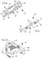
- FIG. 11is an exploded perspective view of an alternative present invention connector assembly
- FIG. 12is a perspective view of the present invention connector assembly shown in FIG. 11, showing various components of the connector assembly, without one of the two housing members and without the insulated conductors installed to the connector assembly;
- FIG. 13is a partial plan view of the present invention connector assembly shown in FIG. 11, showing one of the two flexible piercing terminals piercing the insulation of one of the two insulated conductors installed to one of two housing members of the connector assembly.
- FIG. 1there is shown at 10 a perspective view of the present invention connector assembly fully assembled, with insulated conductors or wires 2 installed thereto.
- the connector assembly 10has means for penetrating the insulation and quickly facilitating and establishing electrical connection with insulated conductors 2 .
- FIG. 3shows an exploded perspective view of the present invention connector assembly 10 .
- FIG. 4shows a perspective view of the present invention connector assembly 10 in the unterminated position or condition, before the insulated conductors 2 are installed and pierced.
- the connector assembly 10comprises a first half housing or shell 12 , a complementary second half housing or shell 14 , a pair of adaptable conductor guides 16 and 18 , a pair of flexible piercing terminals 20 and 22 , and a pair of rotatable cams or levers 24 and 26 .
- Each housinghas a conformed interior compartment 28 which includes a conductor guide location, a piercing terminal location and a cam location.
- the two housings 12 and 14are interconnected together to form a main housing 15 for respectively retaining and securing the conductor guides 16 and 18 , the piercing terminals 20 and 22 , and the rotatable cams 24 and 26 to the guide locations, the piercing terminal locations and the cam locations of the two half housings 12 and 14 .
- the main housing 15has at least two spaced apart apertures 30 (see FIG. 1) located in the longitudinal direction for allowing the insulated conductors 2 to be inserted thereto and two pairs of spaced apart apertures 55 located in the transverse direction.
- the housings 12 and 14are constructed of electrically non-conductive material.
- the conductor guide 16has a semi-cylindrical body 32 which includes two opposite ridges 34 extending along the longitudinal direction of the conductor guide 16 , two opposite arch shaped ends 38 integrally connected to the two opposite ridges 34 , and a plurality of flanges or fingers 36 which extend in the transverse direction of the semi-cylindrical body 32 .
- the conductor guide 16is positioned and secured between the interior compartments 28 of the first and second housings 12 and 14 , where the conductor guide 16 forms a conductor passage which is aligned with one of the at least two spaced apart apertures 30 of the main housing 15 for retaining a plurality of different sized diameter conductors of the insulated conductors 2 .
- the piercing terminal 20is constructed of electrically conductive material and has an elongated thin flat body 21 which includes a flexible portion 64 with a knife shaped or piercing end 66 , a semi-rigid portion 68 with a connection end 70 , and a narrow middle portion 72 interconnecting the flexible portion 64 with the semi-rigid portion 68 .
- connection end 70may have an aperture 76 for providing connection means to the electronic devices, electrical speaker wires, etc.
- the piercing terminal 20is positioned and secured between the interior compartments 28 of the first and second housings 12 and 14 , such that the flanges 74 are positioned within recesses 45 provided by the first and second housings 12 and 14 , and the connection end 70 extends out from the main housing 15 while the knife shaped end 66 is located adjacent to the conductor guide 16 .
- the rotatable cam 24includes a straight or handle portion 48 and a pair of spaced apart arch shaped arms 50 integrally connected to one end of the straight portion 48 .
- an arch shaped engagement portion 52which is integrally formed with the interior side 46 of the straight portion 48 .
- two transverse protruding bosses 54(only one is shown) located on opposite sides of the straight portion 48 of the rotatable cam 24 .
- the rotatable cam 24is positioned and secured between the interior compartments 28 of the first and second housings 12 and 14 , such that the two protruding bosses 54 are inserted into the apertures 55 provided by the first and second housings 12 and 14 .
- the handle portion 48extends out from the main housing 15 while the pair of arch shaped arms 50 are partially within the main housing 15 .
- FIG. 5shows the present invention connector assembly 10 in its unterminated position or condition, before the insulated conductors 2 are pierced.
- FIG. 6shows the present invention connector assembly 10 , where the knife shaped ends 66 of flexible piercing terminals 20 and 22 pierce the insulation of the insulated conductors 2 .
- FIG. 7shows the present invention connector assembly 10 in its terminated position or condition, where the knife shaped ends 66 of the flexible piecing terminals establish electrical connection with the insulated conductors 2 . Referring to FIGS. 1 through 10, the unstripped conductors 2 are respectively inserted into the apertures 30 provided by the main housing 15 and positioned within the conductor guides 16 and 18 .
- the handle portions 48 of the rotatable cams 24 and 26are rotated inwardly such that the arch shaped arms 50 engage and push the ridges 34 of the conductor guides 16 and 18 together to squeeze and secure the conductors 2 thereto (see FIG. 2 ). While the rotatable cams 24 and 26 are being rotated, engagement surfaces 53 of the engagement portions 52 engage and push the flexible portions 64 of the piercing terminals 20 and 22 inwardly such that the knife shaped ends 66 pierce the insulated electrical wires or conductors 2 to establish electrical connection thereto.
- the present inventionhas many advantageous features including: (a) the user does not have to strip the insulation away from the conductors prior to establishing an electrical connection; and (b) the conductor guides will automatically accept conductors between 10 gauge wires through 20 gauge wires without special adapters or adjustment by the user.
- the benefit of present inventionis easy installation which carries over from custom install in-wall speakers and ceiling speakers to standard floor-standing speakers as well as consumer electronics.
- the present inventionconforms to conventional forms of manufacture or any other conventional way known to one skilled in the art.
- the present invention connector assembly 110has means for penetrating the insulation and quickly facilitating and establishing electrical connection with insulated conductors 102 .
- the present invention connector assembly 110can be reused without replacing any components.
- FIG. 11shows an exploded view of the present invention connector assembly 110 .
- FIG. 12shows a perspective view of the present invention connector assembly 110 in the unterminated position or condition, before the insulated conductors 102 are installed and pierced.
- FIG. 13is a partial plan view of the present invention connector assembly 110 , showing one of the two flexible piercing terminals 124 piercing the insulation of one of the two insulated conductors 102 .
- the connector assembly 10comprises a first half housing member or shell 112 , a complementary second half housing member or shell 114 , a pair of elongated flexible piercing terminals 120 and 122 , and a pair of rotatable cams or levers 124 and 126 .
- Each of the first and second housing members 112 and 114has a conformed interior compartment 128 which includes two half conductor channels, two piercing terminal locations and two cam locations.
- the first and second housing members 112 and 114are interconnected together to form a main housing for respectively retaining and securing the piercing terminals 120 and 122 , and the rotatable cams 124 and 126 to the piercing terminal locations and the cam locations of the two half members 112 and 114 .
- the main housinghas at least two spaced apart apertures 130 (see FIG. 12) located at one end 113 aligned in the longitudinal direction for allowing the insulated conductors 102 to be inserted therethrough and two pairs of spaced apart apertures 155 (see FIG. 11) located in the transverse direction.
- the half members 112 and 114are constructed of electrically non-conductive material.
- the piercing terminal 120is constructed of electrically conductive material and has a movable section 164 , a semi-rigid contact section 168 , and a flexible connection section 165 integrally connected between the movable section 164 and the contact section 168 .
- the movable section 164has a knife or piercing means 166 located adjacent to an end 167 of the movable section 164 and a pair of outwardly curved retaining arms or means 169 located adjacent to the piercing means 166 .
- the contact section 168has a pair of parallel flanges 174 for securing the piercing terminal 120 to the main housing.
- the connecting end 170may have an aperture 176 for providing connection means to connect to the electronic devices, electrical speaker wires, etc.
- the piercing terminal 120is positioned and secured between the interior compartments 128 of the first and second half members 112 and 114 , such that the flanges 174 are positioned within recesses 145 provided by the first and second half members 112 and 114 , and the connection end 170 extends out from the other end of the main housing while the movable section 164 is located within the main housing.
- the rotatable cam 124includes a straight or handle section 148 and an engagement section 152 . There are also provided two transverse protruding bosses 154 (only one is shown) located on opposite sides of the rotatable cam 124 . Referring to the left rotatable cam 126 , the engagement section 152 has at least three slots 178 located on the engagement side 180 for accommodating the piercing means 166 and the pair of retaining arms 169 of the piercing terminal 122 . The piercing means 166 and the retaining arms 169 slide within the engagement section 152 and are secured thereto.
- the rotatable cam 124is positioned and secured between the interior compartments 128 of the first and second half members 112 and 114 , such that the two protruding bosses 154 are inserted into the apertures 155 provided by the first and second half members 112 and 114 .
- the handle section 148extends out from the main housing while the engagement section 152 is located within the main housing.
- the knife means 166 of the flexible piercing terminals 120 and 122pierce the insulation of the insulated conductors 102 .
- the knife means 166 of the flexible piecing terminals 120 and 122establish electrical connection with the insulated conductors 102 (see FIG. 13 ).
- the unstripped conductors 102are respectively inserted into the apertures 130 provided by the main housing and positioned within the conductor channels of the main housing.
- the handle sections 148 of the rotatable cams 124 and 126are rotated inwardly such that the engagement sections 152 engage and move the movable sections of the piercing terminals 120 and 122 to the conductors 102 while the retaining means hold the conductors 102 thereto while the piercing means pierce the insulation of the insulated conductors to establish the electrical connections. While the rotatable cams 124 and 126 are being rotated, the engagement sections engage and move the movable sections 164 of the piercing terminals 120 and 122 inwardly such that the knives 166 pierce the insulated electrical wires or conductors 102 to establish electrical connection thereto.
- connector assemblycan be reused without replacing any components.
- the reason why the connector assembly can be reusedis that the piercing terminal 120 does not break off after one usage. With the flexible connection section 165 incorporated between the movable section 164 and the contact section 168 , the piercing terminal 120 will not break-off and can be used many times over without breaking.
- the present inventionhas many advantageous features including: (a) the user does not have to strip the insulation away from the conductors prior to establishing an electrical connection; (b) the connector assembly can accept insulated conductors between 8 gauge wires through 22 gauge wires without special adapters or adjustment by the user;
- the benefit of present inventionis easy installation which carries over from custom install in-wall speakers and ceiling speakers to standard floor-standing speakers as well as consumer electronics.
- the present inventionconforms to conventional forms of manufacture or any other conventional way known to one skilled in the art.
- the present inventionis a connector assembly for quickly facilitating and establishing electrical connection with a pair of insulated conductors, the connector assembly comprising: (a) a first half housing member having an interior compartment; (b) a complementary second half housing member having an interior compartment which is a mirror image of the interior compartment of the first half housing member and mateable with the first half housing member to form a main housing with a pair of spaced apart conductor receiving apertures located at one end of the main housing for receiving a plurality of different sized diameter insulated conductors of the pair of insulated conductors; (c) a pair of spaced apart flexible piercing terminals positioned and secured within the interior compartments of the first and second housing members and located parallel to each other, each piercing terminal having a movable section, a contact section with a connecting end extending out from the other end of the main housing and a flexible connection section integrally connecting the movable section and the contact section, the movable section having a piercing means extending
- the present inventionis a connector assembly for quickly facilitating and establishing electrical connection with at least two insulated conductors, the connector assembly comprising: (a) a first half member; (b) a complementary second half member mateable with the first half member to form a main housing with at least two spaced apart apertures for receiving a plurality of different sized diameter insulated conductors of the at least two insulated conductors; (c) at least two piercing terminals positioned and secured between the first and second members and located parallel to each other, each piercing terminal having a movable section, a contact section extending out from the main housing and a flexible connection section connecting the movable section and the contact section, the movable section having a piercing means extending inwardly and a retaining means located adjacent to the piercing means; and (d) at least two cams rotatably positioned and secured between the first and second members and respectively located adjacent to the at least two piercing terminals, each cam having an engagement
- the present inventionis a connector assembly for quickly facilitating and establishing electrical connection with at least two insulated conductors, the connector assembly comprising: (a) a first half member; (b) a complementary second half member mateable with the first half member to form a main housing with at least two spaced apart apertures for receiving a plurality of different sized diameter insulated conductors of the at two least insulated conductors; (c) at least two piercing terminals installed between the first end second members, each piercing terminal having a movable section, a contact section extending out from the main housing and a flexible section connecting the movable section and the contact section, the movable section having a piercing means and a retaining means; and (d) means for engaging and moving the movable section of the each piercing terminal, such that the retaining means of the movable section of the each piercing terminal engages and holds the each insulated conductor thereto while the piercing means of the movable
- the present inventionis a connector assembly for quickly facilitating and establishing electrical connection with at least one insulated conductor, the connector assembly comprising: (a) a first half member; (b) a second half member mateable with the first half member to form a main housing with at least one aperture for receiving a plurality of different sized diameter conductors of the at least one insulated conductor; (c) at least one piercing terminal installed between the first and second members and having a movable section, a contact section and a flexible section connecting the movable section and the contact section, the movable section having means for holding and penetrating the insulation of the at least one insulated conductor; and (d) at least one cam rotatably installed between the first and second members and having means for engaging and moving the movable section, such that the holding and penetrating means engages and holds the at least one insulated conductor thereto while piercing the insulation of the at least one insulated conductor to establish the electrical connection thereto.
- the present inventionis a connector for quickly facilitating and establishing electrical connection with at least one insulated conductor, the connector comprising: (a) a shell having at least one aperture for receiving the at least one insulated conductor thereto; (b) at least one piercing terminal installed within the shell and having a movable section, a contact section and a flexible section connecting the movable section and the contact section, the movable section having a piercing means and a retaining means; and (c) means for engaging and moving the movable section such that the retaining means engages and holds the at least one insulated conductor thereto while the piercing means pierces the insulation of the at least one insulated conductor to establish the electrical connection thereto.
Landscapes
- Multi-Conductor Connections (AREA)
- Connections By Means Of Piercing Elements, Nuts, Or Screws (AREA)
- Coupling Device And Connection With Printed Circuit (AREA)
Abstract
Description
Claims (29)
Priority Applications (1)
| Application Number | Priority Date | Filing Date | Title |
|---|---|---|---|
| US09/655,468US6305967B1 (en) | 1999-11-23 | 2000-09-05 | Connector assembly having means for penetrating the insulation and establishing electrical connection with the wires |
Applications Claiming Priority (2)
| Application Number | Priority Date | Filing Date | Title |
|---|---|---|---|
| US09/448,358US6159035A (en) | 1999-11-23 | 1999-11-23 | Connector assembly having means for penetrating the insulation and establishing electrical connection with the wires |
| US09/655,468US6305967B1 (en) | 1999-11-23 | 2000-09-05 | Connector assembly having means for penetrating the insulation and establishing electrical connection with the wires |
Related Parent Applications (1)
| Application Number | Title | Priority Date | Filing Date |
|---|---|---|---|
| US09/448,358Continuation-In-PartUS6159035A (en) | 1999-11-23 | 1999-11-23 | Connector assembly having means for penetrating the insulation and establishing electrical connection with the wires |
Publications (1)
| Publication Number | Publication Date |
|---|---|
| US6305967B1true US6305967B1 (en) | 2001-10-23 |
Family
ID=46257210
Family Applications (1)
| Application Number | Title | Priority Date | Filing Date |
|---|---|---|---|
| US09/655,468Expired - LifetimeUS6305967B1 (en) | 1999-11-23 | 2000-09-05 | Connector assembly having means for penetrating the insulation and establishing electrical connection with the wires |
Country Status (1)
| Country | Link |
|---|---|
| US (1) | US6305967B1 (en) |
Cited By (11)
| Publication number | Priority date | Publication date | Assignee | Title |
|---|---|---|---|---|
| US20040253974A1 (en)* | 2003-06-16 | 2004-12-16 | Wan-Pei Kao | Electric plug for use in a mobile electronic apparatus |
| US20060097864A1 (en)* | 2004-11-10 | 2006-05-11 | Lammers Bryan G | System and method for power and data delivery on a machine |
| DE102005005081A1 (en)* | 2005-02-03 | 2006-08-17 | Tyco Electronics Amp Gmbh | Contacting device, for use in electrical power bus system, has contact unit, such that electrical contact is produced between contact unit and one of two electrical conductors, by operation of actuation device |
| US7186132B2 (en) | 2005-05-31 | 2007-03-06 | Raul Quintanilla | Electrical and electronic connector with blade closed by lever |
| US20070141903A1 (en)* | 2005-12-19 | 2007-06-21 | Casperson Paul G | Electrical connector assembly |
| DE102005005082B4 (en)* | 2005-02-03 | 2007-12-06 | Tyco Electronics Amp Gmbh | Electrical connection device and method for connecting electrical conductors and electrical line system |
| US20080182449A1 (en)* | 2004-05-07 | 2008-07-31 | Tyco Thermal Controls Llc | Adjustable Cable Connector Wire Guide and Connector Assembly Incorporating the Same |
| US20090197455A1 (en)* | 2004-07-20 | 2009-08-06 | Vincenzo Corradi | Device for electrical connection of discontinuous conductors |
| US20100207744A1 (en)* | 2004-11-10 | 2010-08-19 | Caterpillar Inc. | System And Method For Power And Data Delivery On A Machine |
| CN105846135A (en)* | 2015-01-29 | 2016-08-10 | 哈默尔Tlc公司 | Electrical connectors and related methods |
| AU2017204634A1 (en)* | 2017-07-06 | 2019-01-24 | Brightgreen Pty Ltd | Electrical connector |
Citations (18)
| Publication number | Priority date | Publication date | Assignee | Title |
|---|---|---|---|---|
| US3816819A (en)* | 1972-10-30 | 1974-06-11 | Gen Electric | Wire connector with wire locating device |
| US3877774A (en)* | 1972-11-28 | 1975-04-15 | Bunker Ramo | Flat cable connector |
| US3976351A (en)* | 1974-12-12 | 1976-08-24 | Mark Products, Inc. | Electrical connector |
| US4157208A (en) | 1977-11-11 | 1979-06-05 | Amp Incorporated | Waterproof splice electrical connector |
| US4253722A (en) | 1979-05-25 | 1981-03-03 | Middleburg Corporation | Insulation pierce-type connector for ribbon cable |
| US4270826A (en)* | 1979-02-01 | 1981-06-02 | Thomas & Betts Corporation | Zero insertion force connector |
| US4451104A (en) | 1982-05-27 | 1984-05-29 | At&T Technologies, Inc. | Apparatus for splicing electric wires |
| US4572603A (en) | 1984-06-29 | 1986-02-25 | Amp, Incorporated | Connector for terminating small gauge magnet wire |
| US4653187A (en) | 1985-10-31 | 1987-03-31 | Molex Incorporated | Connector fabrication method and apparatus |
| US4793823A (en)* | 1987-10-28 | 1988-12-27 | Amp Incorporated | Cam lever connector |
| US4957452A (en)* | 1988-12-14 | 1990-09-18 | Oskar Wortz & Inhaber Hans Woretz | Electrical terminal |
| US5259769A (en) | 1992-09-29 | 1993-11-09 | Molex Incorporated | Electrical connector with preloaded spring-like terminal with improved wiping action |
| US5704801A (en)* | 1996-08-30 | 1998-01-06 | The Whitaker Corporation | Power cable tap connector |
| US5746626A (en) | 1996-10-11 | 1998-05-05 | Bourns, Inc. | Electrical connector assembly |
| US5807133A (en) | 1997-04-15 | 1998-09-15 | Lucent Technologies Inc. | Insulation displacement connector |
| US5975938A (en)* | 1998-06-03 | 1999-11-02 | Robert A. Libby | Quick connect electrical connector for multi conductor insulated cable wiring |
| US6036532A (en)* | 1995-05-04 | 2000-03-14 | Feistkorn; Vera | Electrical connector which strips insulation from an insulated conductor |
| US6159035A (en)* | 1999-11-23 | 2000-12-12 | Audio Components International, Inc. | Connector assembly having means for penetrating the insulation and establishing electrical connection with the wires |
- 2000
- 2000-09-05USUS09/655,468patent/US6305967B1/ennot_activeExpired - Lifetime
Patent Citations (18)
| Publication number | Priority date | Publication date | Assignee | Title |
|---|---|---|---|---|
| US3816819A (en)* | 1972-10-30 | 1974-06-11 | Gen Electric | Wire connector with wire locating device |
| US3877774A (en)* | 1972-11-28 | 1975-04-15 | Bunker Ramo | Flat cable connector |
| US3976351A (en)* | 1974-12-12 | 1976-08-24 | Mark Products, Inc. | Electrical connector |
| US4157208A (en) | 1977-11-11 | 1979-06-05 | Amp Incorporated | Waterproof splice electrical connector |
| US4270826A (en)* | 1979-02-01 | 1981-06-02 | Thomas & Betts Corporation | Zero insertion force connector |
| US4253722A (en) | 1979-05-25 | 1981-03-03 | Middleburg Corporation | Insulation pierce-type connector for ribbon cable |
| US4451104A (en) | 1982-05-27 | 1984-05-29 | At&T Technologies, Inc. | Apparatus for splicing electric wires |
| US4572603A (en) | 1984-06-29 | 1986-02-25 | Amp, Incorporated | Connector for terminating small gauge magnet wire |
| US4653187A (en) | 1985-10-31 | 1987-03-31 | Molex Incorporated | Connector fabrication method and apparatus |
| US4793823A (en)* | 1987-10-28 | 1988-12-27 | Amp Incorporated | Cam lever connector |
| US4957452A (en)* | 1988-12-14 | 1990-09-18 | Oskar Wortz & Inhaber Hans Woretz | Electrical terminal |
| US5259769A (en) | 1992-09-29 | 1993-11-09 | Molex Incorporated | Electrical connector with preloaded spring-like terminal with improved wiping action |
| US6036532A (en)* | 1995-05-04 | 2000-03-14 | Feistkorn; Vera | Electrical connector which strips insulation from an insulated conductor |
| US5704801A (en)* | 1996-08-30 | 1998-01-06 | The Whitaker Corporation | Power cable tap connector |
| US5746626A (en) | 1996-10-11 | 1998-05-05 | Bourns, Inc. | Electrical connector assembly |
| US5807133A (en) | 1997-04-15 | 1998-09-15 | Lucent Technologies Inc. | Insulation displacement connector |
| US5975938A (en)* | 1998-06-03 | 1999-11-02 | Robert A. Libby | Quick connect electrical connector for multi conductor insulated cable wiring |
| US6159035A (en)* | 1999-11-23 | 2000-12-12 | Audio Components International, Inc. | Connector assembly having means for penetrating the insulation and establishing electrical connection with the wires |
Cited By (16)
| Publication number | Priority date | Publication date | Assignee | Title |
|---|---|---|---|---|
| US6965671B2 (en)* | 2003-06-16 | 2005-11-15 | Ing-Ming Lai | Electric plug for use in a mobile electronic apparatus |
| US20040253974A1 (en)* | 2003-06-16 | 2004-12-16 | Wan-Pei Kao | Electric plug for use in a mobile electronic apparatus |
| US20080182449A1 (en)* | 2004-05-07 | 2008-07-31 | Tyco Thermal Controls Llc | Adjustable Cable Connector Wire Guide and Connector Assembly Incorporating the Same |
| US7645173B2 (en) | 2004-05-07 | 2010-01-12 | Tyco Thermal Controls Llc | Adjustable cable connector wire guide and connector assembly incorporating the same |
| US7731521B2 (en)* | 2004-07-20 | 2010-06-08 | Italgenio S.R.L. | Device for electrical connection of discontinuous conductors |
| US20090197455A1 (en)* | 2004-07-20 | 2009-08-06 | Vincenzo Corradi | Device for electrical connection of discontinuous conductors |
| US20100207744A1 (en)* | 2004-11-10 | 2010-08-19 | Caterpillar Inc. | System And Method For Power And Data Delivery On A Machine |
| US20060097864A1 (en)* | 2004-11-10 | 2006-05-11 | Lammers Bryan G | System and method for power and data delivery on a machine |
| US8405500B2 (en) | 2004-11-10 | 2013-03-26 | Caterpillar Inc. | System and method for power and data delivery on a machine |
| DE102005005082B4 (en)* | 2005-02-03 | 2007-12-06 | Tyco Electronics Amp Gmbh | Electrical connection device and method for connecting electrical conductors and electrical line system |
| DE102005005081B4 (en)* | 2005-02-03 | 2006-11-30 | Tyco Electronics Amp Gmbh | Contacting device and method for connecting electrical conductors, contact element and electrical line system |
| DE102005005081A1 (en)* | 2005-02-03 | 2006-08-17 | Tyco Electronics Amp Gmbh | Contacting device, for use in electrical power bus system, has contact unit, such that electrical contact is produced between contact unit and one of two electrical conductors, by operation of actuation device |
| US7186132B2 (en) | 2005-05-31 | 2007-03-06 | Raul Quintanilla | Electrical and electronic connector with blade closed by lever |
| US20070141903A1 (en)* | 2005-12-19 | 2007-06-21 | Casperson Paul G | Electrical connector assembly |
| CN105846135A (en)* | 2015-01-29 | 2016-08-10 | 哈默尔Tlc公司 | Electrical connectors and related methods |
| AU2017204634A1 (en)* | 2017-07-06 | 2019-01-24 | Brightgreen Pty Ltd | Electrical connector |
Similar Documents
| Publication | Publication Date | Title |
|---|---|---|
| US4533199A (en) | IDC termination for coaxial cable | |
| EP0154414B1 (en) | Round cable adaptor for modular plug | |
| US4317608A (en) | Slotted pate terminal for stranded wire | |
| US4460234A (en) | Double-ended modular jack | |
| US4379605A (en) | Electrical receptacle of molded body construction | |
| CA1068364A (en) | Flat conductor cable connector | |
| US7632133B2 (en) | Cross connect terminal block | |
| US6328592B1 (en) | Electrical connector with cable clamping means | |
| CA2516444A1 (en) | System and method for connecting an electrosurgical instrument to a generator | |
| EP0239422A1 (en) | Electrical connector for flexible flat cable | |
| US4533193A (en) | IDC termination for coaxial cable having alignment & stabilizing means | |
| US6305967B1 (en) | Connector assembly having means for penetrating the insulation and establishing electrical connection with the wires | |
| GB1588841A (en) | Electrical terminal assemblies | |
| JPS6130390B2 (en) | ||
| US7140905B2 (en) | Quick wire connect angle plug | |
| US6159035A (en) | Connector assembly having means for penetrating the insulation and establishing electrical connection with the wires | |
| TW201212428A (en) | Coaxial connector and substrate connector | |
| US4564256A (en) | Flat cable transition connector | |
| JPS6028109B2 (en) | electrical terminals | |
| US4124265A (en) | Quick slide connector | |
| JPH0864282A (en) | Electric connector device | |
| US4461527A (en) | Insulation displacing terminal | |
| US7347717B2 (en) | Insulation displacement system | |
| USRE32810E (en) | Electrical contact for terminating insulated conductors | |
| US20100197161A1 (en) | Power outlet |
Legal Events
| Date | Code | Title | Description |
|---|---|---|---|
| AS | Assignment | Owner name:AUDIO COMPONENTS INTERNATIONAL, INC., CALIFORNIA Free format text:ASSIGNMENT OF ASSIGNORS INTEREST;ASSIGNOR:SMITH, LOWELL J. III.;REEL/FRAME:011094/0867 Effective date:20000903 | |
| AS | Assignment | Owner name:NILES AUDIO CORPORATION, FLORIDA Free format text:ASSIGNMENT OF ASSIGNORS INTEREST;ASSIGNOR:AUDIO COMPONENTS INTERNATIONAL, INC.;REEL/FRAME:012040/0540 Effective date:20010723 | |
| STCF | Information on status: patent grant | Free format text:PATENTED CASE | |
| FEPP | Fee payment procedure | Free format text:PAYOR NUMBER ASSIGNED (ORIGINAL EVENT CODE: ASPN); ENTITY STATUS OF PATENT OWNER: SMALL ENTITY | |
| FPAY | Fee payment | Year of fee payment:4 | |
| AS | Assignment | Owner name:NILES AUDIO CORPORATION (A DELAWARE CORP.),FLORIDA Free format text:ASSIGNMENT OF ASSIGNORS INTEREST;ASSIGNOR:NILES AUDIO CORPORATION (A FLORIDA CORPORATION);REEL/FRAME:016891/0366 Effective date:20050714 Owner name:NILES AUDIO CORPORATION (A DELAWARE CORP.), FLORID Free format text:ASSIGNMENT OF ASSIGNORS INTEREST;ASSIGNOR:NILES AUDIO CORPORATION (A FLORIDA CORPORATION);REEL/FRAME:016891/0366 Effective date:20050714 | |
| AS | Assignment | Owner name:UBS AG, STAMFORD BRANCH, AS ADMINISTRATIVE AGENT, Free format text:SECURITY AGREEMENT;ASSIGNOR:NILES AUDIO CORPORATION;REEL/FRAME:018350/0207 Effective date:20050804 | |
| AS | Assignment | Owner name:NORTEK, INC., RHODE ISLAND Free format text:RELEASE OF SECURITY INTEREST IN INTELLECTUAL PROPERTY;ASSIGNOR:UBS AG, STAMFORD BRANCH, AS U.S. ADMINISTRATIVE AGENT;REEL/FRAME:021118/0976 Effective date:20080520 Owner name:NORTEK HOLDINGS, INC., RHODE ISLAND Free format text:RELEASE OF SECURITY INTEREST IN INTELLECTUAL PROPERTY;ASSIGNOR:UBS AG, STAMFORD BRANCH, AS U.S. ADMINISTRATIVE AGENT;REEL/FRAME:021118/0976 Effective date:20080520 Owner name:NILES AUDIO CORPORATION, FLORIDA Free format text:RELEASE OF SECURITY INTEREST IN INTELLECTUAL PROPERTY;ASSIGNOR:UBS AG, STAMFORD BRANCH, AS U.S. ADMINISTRATIVE AGENT;REEL/FRAME:021118/0976 Effective date:20080520 | |
| AS | Assignment | Owner name:BANK OF AMERICA, N.A., NEW YORK Free format text:SECURITY AGREEMENT;ASSIGNORS:NORTEK, INC.;ADVANCED BRIDGING TECHNOLOGIES, INC.;AIGIS MECHTRONICS, INC.;AND OTHERS;REEL/FRAME:021301/0927 Effective date:20080520 Owner name:BANK OF AMERICA, N.A.,NEW YORK Free format text:SECURITY AGREEMENT;ASSIGNORS:NORTEK, INC.;ADVANCED BRIDGING TECHNOLOGIES, INC.;AIGIS MECHTRONICS, INC.;AND OTHERS;REEL/FRAME:021301/0927 Effective date:20080520 | |
| AS | Assignment | Owner name:U.S. BANK NATIONAL ASSOCIATION, MASSACHUSETTS Free format text:SECURITY AGREEMENT;ASSIGNORS:NORTEK, INC.;ADVANCED BRIDGING TECHNOLOGIES, INC.;AIGIS MECHTRONICS, INC.;AND OTHERS;REEL/FRAME:021316/0764 Effective date:20080520 Owner name:U.S. BANK NATIONAL ASSOCIATION,MASSACHUSETTS Free format text:SECURITY AGREEMENT;ASSIGNORS:NORTEK, INC.;ADVANCED BRIDGING TECHNOLOGIES, INC.;AIGIS MECHTRONICS, INC.;AND OTHERS;REEL/FRAME:021316/0764 Effective date:20080520 | |
| FPAY | Fee payment | Year of fee payment:8 | |
| AS | Assignment | Owner name:BANK OF AMERICA, N.A., NEW YORK Free format text:SECURITY AGREEMENT;ASSIGNORS:NORTEK, INC.;AIGIS MECHTRONICS, INC.;BROAN-MEXICO HOLDINGS, INC.;AND OTHERS;REEL/FRAME:023750/0040 Effective date:20091217 Owner name:BANK OF AMERICA, N.A.,NEW YORK Free format text:SECURITY AGREEMENT;ASSIGNORS:NORTEK, INC.;AIGIS MECHTRONICS, INC.;BROAN-MEXICO HOLDINGS, INC.;AND OTHERS;REEL/FRAME:023750/0040 Effective date:20091217 | |
| AS | Assignment | Owner name:NILES AUDIO CORPORATION (A DELAWARE CORP.),FLORIDA Free format text:CORRECTIVE ASSIGNMENT TO CORRECT THE INCORRECT SERIAL NUMBER 10/771,218. THE CORRECT NUMBER IS 10/711,218 PREVIOUSLY RECORDED ON REEL 016891 FRAME 0366. ASSIGNOR(S) HEREBY CONFIRMS THE ASSIGNMENT - ASSIGNMENT OF ASSIGNOR'S INTEREST;ASSIGNOR:NILES AUDIO CORPORATION (A FLORIDA CORPORATION);REEL/FRAME:024599/0493 Effective date:20050714 | |
| AS | Assignment | Owner name:AVC GROUP, LLC, THE, CALIFORNIA Free format text:ASSIGNMENT OF ASSIGNORS INTEREST;ASSIGNOR:NILES AUDIO CORPORATION;REEL/FRAME:025865/0441 Effective date:20110129 | |
| AS | Assignment | Owner name:MAGENTA RESEARCH LTD., A CONNECTICUT CORPORATION, Free format text:PATENT RELEASE;ASSIGNOR:U.S BANK NATIONAL ASSOCIATION;REEL/FRAME:026275/0964 Effective date:20110426 Owner name:BROAN-NUTONE STORAGE SOLUTIONS LP, A DELAWARE LIMI Free format text:PATENT RELEASE;ASSIGNOR:U.S BANK NATIONAL ASSOCIATION;REEL/FRAME:026275/0964 Effective date:20110426 Owner name:VENMAR CES, INC., A CANADIAN CORPORATION, CANADA Free format text:PATENT RELEASE;ASSIGNOR:U.S BANK NATIONAL ASSOCIATION;REEL/FRAME:026275/0964 Effective date:20110426 Owner name:AVC GROUP, LLC, THE, A DELAWARE LLC, CALIFORNIA Free format text:PATENT RELEASE;ASSIGNOR:U.S BANK NATIONAL ASSOCIATION;REEL/FRAME:026275/0964 Effective date:20110426 Owner name:OMNIMOUNT SYSTEMS, INC., A ARIZONA CORPORATION, AR Free format text:PATENT RELEASE;ASSIGNOR:U.S BANK NATIONAL ASSOCIATION;REEL/FRAME:026275/0964 Effective date:20110426 Owner name:SPEAKERCRAFT, LLC, A DELAWARE LLC, CALIFORNIA Free format text:PATENT RELEASE;ASSIGNOR:U.S BANK NATIONAL ASSOCIATION;REEL/FRAME:026275/0964 Effective date:20110426 Owner name:PANAMAX LLC, A CALIFORNIA LLC, CALIFORNIA Free format text:PATENT RELEASE;ASSIGNOR:U.S BANK NATIONAL ASSOCIATION;REEL/FRAME:026275/0964 Effective date:20110426 Owner name:LINEAR LLC, A CALIFORNIA LLC, CALIFORNIA Free format text:PATENT RELEASE;ASSIGNOR:U.S BANK NATIONAL ASSOCIATION;REEL/FRAME:026275/0964 Effective date:20110426 Owner name:BROAN-NUTONE LLC, A DELAWARE LLC, WISCONSIN Free format text:PATENT RELEASE;ASSIGNOR:U.S BANK NATIONAL ASSOCIATION;REEL/FRAME:026275/0964 Effective date:20110426 Owner name:SECURE WIRELESS, INC., A CALIFORNIA CORPORATION, C Free format text:PATENT RELEASE;ASSIGNOR:U.S BANK NATIONAL ASSOCIATION;REEL/FRAME:026275/0964 Effective date:20110426 Owner name:GATES THAT OPEN, LLC, A FLORIDA LLC, FLORIDA Free format text:PATENT RELEASE;ASSIGNOR:U.S BANK NATIONAL ASSOCIATION;REEL/FRAME:026275/0964 Effective date:20110426 Owner name:NORDYNE LLC, A DELAWARE LLC, MISSOURI Free format text:PATENT RELEASE;ASSIGNOR:U.S BANK NATIONAL ASSOCIATION;REEL/FRAME:026275/0964 Effective date:20110426 Owner name:VENMAR VENTILATION INC., CANADIAN CORPORATION, QUE Free format text:PATENT RELEASE;ASSIGNOR:U.S BANK NATIONAL ASSOCIATION;REEL/FRAME:026275/0964 Effective date:20110426 Owner name:HUNTAIR, INC., A DELAWARE CORPORATION, OREGON Free format text:PATENT RELEASE;ASSIGNOR:U.S BANK NATIONAL ASSOCIATION;REEL/FRAME:026275/0964 Effective date:20110426 Owner name:UBS AG, STAMFORD BRANCH, AS COLLATERAL AGENT, CONN Free format text:SECURITY AGREEMENT;ASSIGNORS:BROAN-NUTONE LLC, A DELAWARE LLC;BROAN-NUTONE STORAGE SOLUTIONS LP, A DELAWARE LIMITED PARTNERSHIP;ERGOTRON, INC., A MINNESOTA CORPORATION;AND OTHERS;REEL/FRAME:026276/0073 Effective date:20110426 | |
| AS | Assignment | Owner name:CORE BRANDS, LLC, CALIFORNIA Free format text:MERGER AND CHANGE OF NAME;ASSIGNOR:AVC GROUP, LLC, THE;REEL/FRAME:029708/0262 Effective date:20130101 | |
| FPAY | Fee payment | Year of fee payment:12 | |
| AS | Assignment | Owner name:BROAN-NUTONE STORAGE SOLUTIONS LP, WISCONSIN Free format text:NOTICE OF RELEASE OF SECURITY INTERESTS IN PATENTS RECORDED AT REEL 026276, FRAME 0073;ASSIGNOR:UBS AG, STAMFORD BRANCH, AS COLLATERAL AGENT;REEL/FRAME:033083/0001 Effective date:20140430 Owner name:NORDYNE LLC, MISSOURI Free format text:NOTICE OF RELEASE OF SECURITY INTERESTS IN PATENTS RECORDED AT REEL 026276, FRAME 0073;ASSIGNOR:UBS AG, STAMFORD BRANCH, AS COLLATERAL AGENT;REEL/FRAME:033083/0001 Effective date:20140430 Owner name:GTO ACCESS SYSTEMS, LLC (F/K/A GATES THAT OPEN, LL Free format text:NOTICE OF RELEASE OF SECURITY INTERESTS IN PATENTS RECORDED AT REEL 026276, FRAME 0073;ASSIGNOR:UBS AG, STAMFORD BRANCH, AS COLLATERAL AGENT;REEL/FRAME:033083/0001 Effective date:20140430 Owner name:CORE BRANDS, LLC (F/K/A PANAMAX LLC), CALIFORNIA Free format text:NOTICE OF RELEASE OF SECURITY INTERESTS IN PATENTS RECORDED AT REEL 026276, FRAME 0073;ASSIGNOR:UBS AG, STAMFORD BRANCH, AS COLLATERAL AGENT;REEL/FRAME:033083/0001 Effective date:20140430 Owner name:LINEAR LLC (SUCCESSOR BY MERGER TO SECURE WIRELESS Free format text:NOTICE OF RELEASE OF SECURITY INTERESTS IN PATENTS RECORDED AT REEL 026276, FRAME 0073;ASSIGNOR:UBS AG, STAMFORD BRANCH, AS COLLATERAL AGENT;REEL/FRAME:033083/0001 Effective date:20140430 Owner name:CES GROUP, LLC (SUCCESSOR BY MERGER TO HUNTAIR, IN Free format text:NOTICE OF RELEASE OF SECURITY INTERESTS IN PATENTS RECORDED AT REEL 026276, FRAME 0073;ASSIGNOR:UBS AG, STAMFORD BRANCH, AS COLLATERAL AGENT;REEL/FRAME:033083/0001 Effective date:20140430 Owner name:MAGENTA RESEARCH LTD., KENTUCKY Free format text:NOTICE OF RELEASE OF SECURITY INTERESTS IN PATENTS RECORDED AT REEL 026276, FRAME 0073;ASSIGNOR:UBS AG, STAMFORD BRANCH, AS COLLATERAL AGENT;REEL/FRAME:033083/0001 Effective date:20140430 Owner name:CORE BRANDS, LLC (SUCCESSOR BY MERGER TO THE AVC G Free format text:NOTICE OF RELEASE OF SECURITY INTERESTS IN PATENTS RECORDED AT REEL 026276, FRAME 0073;ASSIGNOR:UBS AG, STAMFORD BRANCH, AS COLLATERAL AGENT;REEL/FRAME:033083/0001 Effective date:20140430 Owner name:CORE BRANDS, LLC (SUCCESSOR BY MERGER TO SPEAKERCR Free format text:NOTICE OF RELEASE OF SECURITY INTERESTS IN PATENTS RECORDED AT REEL 026276, FRAME 0073;ASSIGNOR:UBS AG, STAMFORD BRANCH, AS COLLATERAL AGENT;REEL/FRAME:033083/0001 Effective date:20140430 Owner name:ERGOTRON, INC., MINNESOTA Free format text:NOTICE OF RELEASE OF SECURITY INTERESTS IN PATENTS RECORDED AT REEL 026276, FRAME 0073;ASSIGNOR:UBS AG, STAMFORD BRANCH, AS COLLATERAL AGENT;REEL/FRAME:033083/0001 Effective date:20140430 Owner name:ERGOTRON, INC. (SUCCESSOR BY MERGER TO OMNIMOUNT S Free format text:NOTICE OF RELEASE OF SECURITY INTERESTS IN PATENTS RECORDED AT REEL 026276, FRAME 0073;ASSIGNOR:UBS AG, STAMFORD BRANCH, AS COLLATERAL AGENT;REEL/FRAME:033083/0001 Effective date:20140430 Owner name:LINEAR LLC, CALIFORNIA Free format text:NOTICE OF RELEASE OF SECURITY INTERESTS IN PATENTS RECORDED AT REEL 026276, FRAME 0073;ASSIGNOR:UBS AG, STAMFORD BRANCH, AS COLLATERAL AGENT;REEL/FRAME:033083/0001 Effective date:20140430 Owner name:BROAN-NUTONE LLC, WISCONSIN Free format text:NOTICE OF RELEASE OF SECURITY INTERESTS IN PATENTS RECORDED AT REEL 026276, FRAME 0073;ASSIGNOR:UBS AG, STAMFORD BRANCH, AS COLLATERAL AGENT;REEL/FRAME:033083/0001 Effective date:20140430 | |
| AS | Assignment | Owner name:GTO, INC., FLORIDA Free format text:NOTICE OF RELEASE OF SECURITY INTEREST IN PATENTS;ASSIGNOR:BANK OF AMERICA, N.A.;REEL/FRAME:041326/0071 Effective date:20160831 Owner name:NORTEK, INC., RHODE ISLAND Free format text:NOTICE OF RELEASE OF SECURITY INTEREST IN PATENTS;ASSIGNOR:BANK OF AMERICA, N.A.;REEL/FRAME:041326/0071 Effective date:20160831 Owner name:RANGAIRE LP, INC., RHODE ISLAND Free format text:NOTICE OF RELEASE OF SECURITY INTEREST IN PATENTS;ASSIGNOR:BANK OF AMERICA, N.A.;REEL/FRAME:041326/0071 Effective date:20160831 Owner name:OMNIMOUNT SYSTEMS, INC., MINNESOTA Free format text:NOTICE OF RELEASE OF SECURITY INTEREST IN PATENTS;ASSIGNOR:BANK OF AMERICA, N.A.;REEL/FRAME:041326/0071 Effective date:20160831 Owner name:ZEPHYR CORPORATION, CALIFORNIA Free format text:NOTICE OF RELEASE OF SECURITY INTEREST IN PATENTS;ASSIGNOR:BANK OF AMERICA, N.A.;REEL/FRAME:041326/0071 Effective date:20160831 Owner name:ALLSTAR PRO, LLC, CALIFORNIA Free format text:NOTICE OF RELEASE OF SECURITY INTEREST IN PATENTS;ASSIGNOR:BANK OF AMERICA, N.A.;REEL/FRAME:041326/0071 Effective date:20160831 Owner name:NILES AUDIO CORPORATION, CALIFORNIA Free format text:NOTICE OF RELEASE OF SECURITY INTEREST IN PATENTS;ASSIGNOR:BANK OF AMERICA, N.A.;REEL/FRAME:041326/0071 Effective date:20160831 Owner name:ADVANCED BRIDGING TECHNOLOGIES, INC., CALIFORNIA Free format text:NOTICE OF RELEASE OF SECURITY INTEREST IN PATENTS;ASSIGNOR:BANK OF AMERICA, N.A.;REEL/FRAME:041326/0071 Effective date:20160831 Owner name:RANGAIRE GP, INC., RHODE ISLAND Free format text:NOTICE OF RELEASE OF SECURITY INTEREST IN PATENTS;ASSIGNOR:BANK OF AMERICA, N.A.;REEL/FRAME:041326/0071 Effective date:20160831 Owner name:BROAN-NUTONE LLC, WISCONSIN Free format text:NOTICE OF RELEASE OF SECURITY INTEREST IN PATENTS;ASSIGNOR:BANK OF AMERICA, N.A.;REEL/FRAME:041326/0071 Effective date:20160831 Owner name:NORTEK INTERNATIONAL, INC., RHODE ISLAND Free format text:NOTICE OF RELEASE OF SECURITY INTEREST IN PATENTS;ASSIGNOR:BANK OF AMERICA, N.A.;REEL/FRAME:041326/0071 Effective date:20160831 Owner name:TEMTROL, INC., MINNESOTA Free format text:NOTICE OF RELEASE OF SECURITY INTEREST IN PATENTS;ASSIGNOR:BANK OF AMERICA, N.A.;REEL/FRAME:041326/0071 Effective date:20160831 Owner name:RANGAIRE LP, RHODE ISLAND Free format text:NOTICE OF RELEASE OF SECURITY INTEREST IN PATENTS;ASSIGNOR:BANK OF AMERICA, N.A.;REEL/FRAME:041326/0071 Effective date:20160831 Owner name:HUNTAIR, INC., MINNESOTA Free format text:NOTICE OF RELEASE OF SECURITY INTEREST IN PATENTS;ASSIGNOR:BANK OF AMERICA, N.A.;REEL/FRAME:041326/0071 Effective date:20160831 Owner name:OPERATOR SPECIALTY COMPANY, INC., MICHIGAN Free format text:NOTICE OF RELEASE OF SECURITY INTEREST IN PATENTS;ASSIGNOR:BANK OF AMERICA, N.A.;REEL/FRAME:041326/0071 Effective date:20160831 Owner name:AUBREY MANUFACTURING, INC., WISCONSIN Free format text:NOTICE OF RELEASE OF SECURITY INTEREST IN PATENTS;ASSIGNOR:BANK OF AMERICA, N.A.;REEL/FRAME:041326/0071 Effective date:20160831 Owner name:SECURE WIRELESS, INC., CALIFORNIA Free format text:NOTICE OF RELEASE OF SECURITY INTEREST IN PATENTS;ASSIGNOR:BANK OF AMERICA, N.A.;REEL/FRAME:041326/0071 Effective date:20160831 Owner name:MAGENTA RESEARCH LTD., RHODE ISLAND Free format text:NOTICE OF RELEASE OF SECURITY INTEREST IN PATENTS;ASSIGNOR:BANK OF AMERICA, N.A.;REEL/FRAME:041326/0071 Effective date:20160831 Owner name:HOMELOGIC LLC, CALIFORNIA Free format text:NOTICE OF RELEASE OF SECURITY INTEREST IN PATENTS;ASSIGNOR:BANK OF AMERICA, N.A.;REEL/FRAME:041326/0071 Effective date:20160831 Owner name:NORDYNE INTERNATIONAL, INC., FLORIDA Free format text:NOTICE OF RELEASE OF SECURITY INTEREST IN PATENTS;ASSIGNOR:BANK OF AMERICA, N.A.;REEL/FRAME:041326/0071 Effective date:20160831 Owner name:WDS LLC, RHODE ISLAND Free format text:NOTICE OF RELEASE OF SECURITY INTEREST IN PATENTS;ASSIGNOR:BANK OF AMERICA, N.A.;REEL/FRAME:041326/0071 Effective date:20160831 Owner name:MAMMOTH, INC., MINNESOTA Free format text:NOTICE OF RELEASE OF SECURITY INTEREST IN PATENTS;ASSIGNOR:BANK OF AMERICA, N.A.;REEL/FRAME:041326/0071 Effective date:20160831 Owner name:PACIFIC ZEPHYR RANGE HOOD, INC., CALIFORNIA Free format text:NOTICE OF RELEASE OF SECURITY INTEREST IN PATENTS;ASSIGNOR:BANK OF AMERICA, N.A.;REEL/FRAME:041326/0071 Effective date:20160831 Owner name:NORDYNE INC., MISSOURI Free format text:NOTICE OF RELEASE OF SECURITY INTEREST IN PATENTS;ASSIGNOR:BANK OF AMERICA, N.A.;REEL/FRAME:041326/0071 Effective date:20160831 Owner name:LINEAR H.K. LLC, CALIFORNIA Free format text:NOTICE OF RELEASE OF SECURITY INTEREST IN PATENTS;ASSIGNOR:BANK OF AMERICA, N.A.;REEL/FRAME:041326/0071 Effective date:20160831 Owner name:GOVERNAIR CORPORATION, MINNESOTA Free format text:NOTICE OF RELEASE OF SECURITY INTEREST IN PATENTS;ASSIGNOR:BANK OF AMERICA, N.A.;REEL/FRAME:041326/0071 Effective date:20160831 Owner name:CES GROUP, INC., MINNESOTA Free format text:NOTICE OF RELEASE OF SECURITY INTEREST IN PATENTS;ASSIGNOR:BANK OF AMERICA, N.A.;REEL/FRAME:041326/0071 Effective date:20160831 Owner name:LITETOUCH, INC., RHODE ISLAND Free format text:NOTICE OF RELEASE OF SECURITY INTEREST IN PATENTS;ASSIGNOR:BANK OF AMERICA, N.A.;REEL/FRAME:041326/0071 Effective date:20160831 Owner name:PANAMAX INC., CALIFORNIA Free format text:NOTICE OF RELEASE OF SECURITY INTEREST IN PATENTS;ASSIGNOR:BANK OF AMERICA, N.A.;REEL/FRAME:041326/0071 Effective date:20160831 Owner name:NUTONE INC., WISCONSIN Free format text:NOTICE OF RELEASE OF SECURITY INTEREST IN PATENTS;ASSIGNOR:BANK OF AMERICA, N.A.;REEL/FRAME:041326/0071 Effective date:20160831 Owner name:CLEANPAK INTERNATIONAL, INC., MINNESOTA Free format text:NOTICE OF RELEASE OF SECURITY INTEREST IN PATENTS;ASSIGNOR:BANK OF AMERICA, N.A.;REEL/FRAME:041326/0071 Effective date:20160831 Owner name:GEFEN, INC., CALIFORNIA Free format text:NOTICE OF RELEASE OF SECURITY INTEREST IN PATENTS;ASSIGNOR:BANK OF AMERICA, N.A.;REEL/FRAME:041326/0071 Effective date:20160831 Owner name:LINEAR LLC, CALIFORNIA Free format text:NOTICE OF RELEASE OF SECURITY INTEREST IN PATENTS;ASSIGNOR:BANK OF AMERICA, N.A.;REEL/FRAME:041326/0071 Effective date:20160831 Owner name:HC INSTALLATIONS, INC., MINNESOTA Free format text:NOTICE OF RELEASE OF SECURITY INTEREST IN PATENTS;ASSIGNOR:BANK OF AMERICA, N.A.;REEL/FRAME:041326/0071 Effective date:20160831 Owner name:JENSEN INDUSTRIES, INC., WISCONSIN Free format text:NOTICE OF RELEASE OF SECURITY INTEREST IN PATENTS;ASSIGNOR:BANK OF AMERICA, N.A.;REEL/FRAME:041326/0071 Effective date:20160831 Owner name:AIGIS MECHTRONICS, INC., CALIFORNIA Free format text:NOTICE OF RELEASE OF SECURITY INTEREST IN PATENTS;ASSIGNOR:BANK OF AMERICA, N.A.;REEL/FRAME:041326/0071 Effective date:20160831 Owner name:SPEAKERCRAFT, INC., CALIFORNIA Free format text:NOTICE OF RELEASE OF SECURITY INTEREST IN PATENTS;ASSIGNOR:BANK OF AMERICA, N.A.;REEL/FRAME:041326/0071 Effective date:20160831 Owner name:NORDYNE CHINA LLC, MINNESOTA Free format text:NOTICE OF RELEASE OF SECURITY INTEREST IN PATENTS;ASSIGNOR:BANK OF AMERICA, N.A.;REEL/FRAME:041326/0071 Effective date:20160831 Owner name:XANTECH CORPORATION, CALIFORNIA Free format text:NOTICE OF RELEASE OF SECURITY INTEREST IN PATENTS;ASSIGNOR:BANK OF AMERICA, N.A.;REEL/FRAME:041326/0071 Effective date:20160831 Owner name:J.A.R. INDUSTRIES, INC., MINNESOTA Free format text:NOTICE OF RELEASE OF SECURITY INTEREST IN PATENTS;ASSIGNOR:BANK OF AMERICA, N.A.;REEL/FRAME:041326/0071 Effective date:20160831 Owner name:ELAN HOME SYSTEMS, L.L.C., CALIFORNIA Free format text:NOTICE OF RELEASE OF SECURITY INTEREST IN PATENTS;ASSIGNOR:BANK OF AMERICA, N.A.;REEL/FRAME:041326/0071 Effective date:20160831 Owner name:WEBCO, INC., MINNESOTA Free format text:NOTICE OF RELEASE OF SECURITY INTEREST IN PATENTS;ASSIGNOR:BANK OF AMERICA, N.A.;REEL/FRAME:041326/0071 Effective date:20160831 Owner name:INTERNATIONAL ELECTRONICS, INC., CALIFORNIA Free format text:NOTICE OF RELEASE OF SECURITY INTEREST IN PATENTS;ASSIGNOR:BANK OF AMERICA, N.A.;REEL/FRAME:041326/0071 Effective date:20160831 Owner name:BROAN-MEXICO HOLDINGS, INC., RHODE ISLAND Free format text:TERMINATION AND RELEASE OF SECURITY IN PATENTS;ASSIGNOR:BANK OF AMERICA, N.A.;REEL/FRAME:041327/0089 Effective date:20160831 Owner name:HC INSTALLATIONS, INC., MINNESOTA Free format text:TERMINATION AND RELEASE OF SECURITY IN PATENTS;ASSIGNOR:BANK OF AMERICA, N.A.;REEL/FRAME:041327/0089 Effective date:20160831 Owner name:PANAMAX LLC, CALIFORNIA Free format text:TERMINATION AND RELEASE OF SECURITY IN PATENTS;ASSIGNOR:BANK OF AMERICA, N.A.;REEL/FRAME:041327/0089 Effective date:20160831 Owner name:SPEAKERCRAFT, LLC, CALIFORNIA Free format text:TERMINATION AND RELEASE OF SECURITY IN PATENTS;ASSIGNOR:BANK OF AMERICA, N.A.;REEL/FRAME:041327/0089 Effective date:20160831 Owner name:CES GROUP, INC., MINNESOTA Free format text:TERMINATION AND RELEASE OF SECURITY IN PATENTS;ASSIGNOR:BANK OF AMERICA, N.A.;REEL/FRAME:041327/0089 Effective date:20160831 Owner name:RANGAIRE LP, INC., RHODE ISLAND Free format text:TERMINATION AND RELEASE OF SECURITY IN PATENTS;ASSIGNOR:BANK OF AMERICA, N.A.;REEL/FRAME:041327/0089 Effective date:20160831 Owner name:NORDYNE INTERNATIONAL, INC., FLORIDA Free format text:TERMINATION AND RELEASE OF SECURITY IN PATENTS;ASSIGNOR:BANK OF AMERICA, N.A.;REEL/FRAME:041327/0089 Effective date:20160831 Owner name:INTERNATIONAL ELECTRONICS, LLC, CALIFORNIA Free format text:TERMINATION AND RELEASE OF SECURITY IN PATENTS;ASSIGNOR:BANK OF AMERICA, N.A.;REEL/FRAME:041327/0089 Effective date:20160831 Owner name:GOVERNAIR CORPORATION, MINNESOTA Free format text:TERMINATION AND RELEASE OF SECURITY IN PATENTS;ASSIGNOR:BANK OF AMERICA, N.A.;REEL/FRAME:041327/0089 Effective date:20160831 Owner name:BROAN-NUTONE STORAGE SOLUTIONS LP, WISCONSIN Free format text:TERMINATION AND RELEASE OF SECURITY IN PATENTS;ASSIGNOR:BANK OF AMERICA, N.A.;REEL/FRAME:041327/0089 Effective date:20160831 Owner name:NILES AUDIO CORPORATION, CALIFORNIA Free format text:TERMINATION AND RELEASE OF SECURITY IN PATENTS;ASSIGNOR:BANK OF AMERICA, N.A.;REEL/FRAME:041327/0089 Effective date:20160831 Owner name:CLEANPAK INTERNATIONAL, INC., MINNESOTA Free format text:TERMINATION AND RELEASE OF SECURITY IN PATENTS;ASSIGNOR:BANK OF AMERICA, N.A.;REEL/FRAME:041327/0089 Effective date:20160831 Owner name:LITE TOUCH, INC., RHODE ISLAND Free format text:TERMINATION AND RELEASE OF SECURITY IN PATENTS;ASSIGNOR:BANK OF AMERICA, N.A.;REEL/FRAME:041327/0089 Effective date:20160831 Owner name:TEMTROL, INC., MINNESOTA Free format text:TERMINATION AND RELEASE OF SECURITY IN PATENTS;ASSIGNOR:BANK OF AMERICA, N.A.;REEL/FRAME:041327/0089 Effective date:20160831 Owner name:SECURE WIRELESS, INC., CALIFORNIA Free format text:TERMINATION AND RELEASE OF SECURITY IN PATENTS;ASSIGNOR:BANK OF AMERICA, N.A.;REEL/FRAME:041327/0089 Effective date:20160831 Owner name:AIGIS MECHTRONICS, INC., CALIFORNIA Free format text:TERMINATION AND RELEASE OF SECURITY IN PATENTS;ASSIGNOR:BANK OF AMERICA, N.A.;REEL/FRAME:041327/0089 Effective date:20160831 Owner name:RANGAIRE GP, INC., RHODE ISLAND Free format text:TERMINATION AND RELEASE OF SECURITY IN PATENTS;ASSIGNOR:BANK OF AMERICA, N.A.;REEL/FRAME:041327/0089 Effective date:20160831 Owner name:NORTEK INTERNATIONAL, INC., RHODE ISLAND Free format text:TERMINATION AND RELEASE OF SECURITY IN PATENTS;ASSIGNOR:BANK OF AMERICA, N.A.;REEL/FRAME:041327/0089 Effective date:20160831 Owner name:MAMMOTH-WEBCO, INC., MINNESOTA Free format text:TERMINATION AND RELEASE OF SECURITY IN PATENTS;ASSIGNOR:BANK OF AMERICA, N.A.;REEL/FRAME:041327/0089 Effective date:20160831 Owner name:ELAN HOME SYSTEMS, L.L.C., CALIFORNIA Free format text:TERMINATION AND RELEASE OF SECURITY IN PATENTS;ASSIGNOR:BANK OF AMERICA, N.A.;REEL/FRAME:041327/0089 Effective date:20160831 Owner name:XANTECH LLC, CALIFORNIA Free format text:TERMINATION AND RELEASE OF SECURITY IN PATENTS;ASSIGNOR:BANK OF AMERICA, N.A.;REEL/FRAME:041327/0089 Effective date:20160831 Owner name:HUNTAIR, INC., MINNESOTA Free format text:TERMINATION AND RELEASE OF SECURITY IN PATENTS;ASSIGNOR:BANK OF AMERICA, N.A.;REEL/FRAME:041327/0089 Effective date:20160831 Owner name:BROAN-NUTONE LLC, WISCONSIN Free format text:TERMINATION AND RELEASE OF SECURITY IN PATENTS;ASSIGNOR:BANK OF AMERICA, N.A.;REEL/FRAME:041327/0089 Effective date:20160831 Owner name:PACIFIC ZEPHYR RANGE HOOD, INC., CALIFORNIA Free format text:TERMINATION AND RELEASE OF SECURITY IN PATENTS;ASSIGNOR:BANK OF AMERICA, N.A.;REEL/FRAME:041327/0089 Effective date:20160831 Owner name:GATES THAT OPEN, LLC, FLORIDA Free format text:TERMINATION AND RELEASE OF SECURITY IN PATENTS;ASSIGNOR:BANK OF AMERICA, N.A.;REEL/FRAME:041327/0089 Effective date:20160831 Owner name:MAGENTA RESEARCH LTD., RHODE ISLAND Free format text:TERMINATION AND RELEASE OF SECURITY IN PATENTS;ASSIGNOR:BANK OF AMERICA, N.A.;REEL/FRAME:041327/0089 Effective date:20160831 Owner name:OPERATOR SPECIALTY COMPANY, INC., MICHIGAN Free format text:TERMINATION AND RELEASE OF SECURITY IN PATENTS;ASSIGNOR:BANK OF AMERICA, N.A.;REEL/FRAME:041327/0089 Effective date:20160831 Owner name:CES INTERNATIONAL LTD., MINNESOTA Free format text:TERMINATION AND RELEASE OF SECURITY IN PATENTS;ASSIGNOR:BANK OF AMERICA, N.A.;REEL/FRAME:041327/0089 Effective date:20160831 Owner name:NORDYNE LLC, MISSOURI Free format text:TERMINATION AND RELEASE OF SECURITY IN PATENTS;ASSIGNOR:BANK OF AMERICA, N.A.;REEL/FRAME:041327/0089 Effective date:20160831 Owner name:NORTEK, INC., RHODE ISLAND Free format text:TERMINATION AND RELEASE OF SECURITY IN PATENTS;ASSIGNOR:BANK OF AMERICA, N.A.;REEL/FRAME:041327/0089 Effective date:20160831 Owner name:NUTONE LLC, WISCONSIN Free format text:TERMINATION AND RELEASE OF SECURITY IN PATENTS;ASSIGNOR:BANK OF AMERICA, N.A.;REEL/FRAME:041327/0089 Effective date:20160831 Owner name:OMNIMOUNT SYSTEMS, INC., MINNESOTA Free format text:TERMINATION AND RELEASE OF SECURITY IN PATENTS;ASSIGNOR:BANK OF AMERICA, N.A.;REEL/FRAME:041327/0089 Effective date:20160831 Owner name:ZEPHYR VENTILATION, LLC, CALIFORNIA Free format text:TERMINATION AND RELEASE OF SECURITY IN PATENTS;ASSIGNOR:BANK OF AMERICA, N.A.;REEL/FRAME:041327/0089 Effective date:20160831 Owner name:GEFEN, LLC, CALIFORNIA Free format text:TERMINATION AND RELEASE OF SECURITY IN PATENTS;ASSIGNOR:BANK OF AMERICA, N.A.;REEL/FRAME:041327/0089 Effective date:20160831 Owner name:LINEAR LLC, CALIFORNIA Free format text:TERMINATION AND RELEASE OF SECURITY IN PATENTS;ASSIGNOR:BANK OF AMERICA, N.A.;REEL/FRAME:041327/0089 Effective date:20160831 | |
| AS | Assignment | Owner name:BROAN-NUTONE LLC, WISCONSIN Free format text:RELEASE BY SECURED PARTY;ASSIGNOR:U.S. BANK NATIONAL ASSOCIATION;REEL/FRAME:056614/0709 Effective date:20210606 Owner name:NORTEK AIR SOLUTIONS, LLC, RHODE ISLAND Free format text:RELEASE BY SECURED PARTY;ASSIGNOR:U.S. BANK NATIONAL ASSOCIATION;REEL/FRAME:056614/0709 Effective date:20210606 Owner name:NORTEK GLOBAL HVAC LLC, RHODE ISLAND Free format text:RELEASE BY SECURED PARTY;ASSIGNOR:U.S. BANK NATIONAL ASSOCIATION;REEL/FRAME:056614/0709 Effective date:20210606 Owner name:NORTEK, INC., RHODE ISLAND Free format text:RELEASE BY SECURED PARTY;ASSIGNOR:U.S. BANK NATIONAL ASSOCIATION;REEL/FRAME:056614/0709 Effective date:20210606 Owner name:ADVANCED BRIDGING TECHNOLOGIES, INC., CALIFORNIA Free format text:RELEASE BY SECURED PARTY;ASSIGNOR:U.S. BANK NATIONAL ASSOCIATION;REEL/FRAME:056614/0709 Effective date:20210606 Owner name:AIGIS MECHTRONICS, INC., NORTH CAROLINA Free format text:RELEASE BY SECURED PARTY;ASSIGNOR:U.S. BANK NATIONAL ASSOCIATION;REEL/FRAME:056614/0709 Effective date:20210606 Owner name:ALLSTAR PRO, LLC, PENNSYLVANIA Free format text:RELEASE BY SECURED PARTY;ASSIGNOR:U.S. BANK NATIONAL ASSOCIATION;REEL/FRAME:056614/0709 Effective date:20210606 Owner name:ELAN HOME SYSTEMS, L.L.C., CALIFORNIA Free format text:RELEASE BY SECURED PARTY;ASSIGNOR:U.S. BANK NATIONAL ASSOCIATION;REEL/FRAME:056614/0709 Effective date:20210606 Owner name:GEFEN, INC., CALIFORNIA Free format text:RELEASE BY SECURED PARTY;ASSIGNOR:U.S. BANK NATIONAL ASSOCIATION;REEL/FRAME:056614/0709 Effective date:20210606 Owner name:GTO, INC., FLORIDA Free format text:RELEASE BY SECURED PARTY;ASSIGNOR:U.S. BANK NATIONAL ASSOCIATION;REEL/FRAME:056614/0709 Effective date:20210606 Owner name:HOMELOGIC LLC, MASSACHUSETTS Free format text:RELEASE BY SECURED PARTY;ASSIGNOR:U.S. BANK NATIONAL ASSOCIATION;REEL/FRAME:056614/0709 Effective date:20210606 Owner name:INTERNATIONAL ELECTRONICS, INC., CALIFORNIA Free format text:RELEASE BY SECURED PARTY;ASSIGNOR:U.S. BANK NATIONAL ASSOCIATION;REEL/FRAME:056614/0709 Effective date:20210606 Owner name:JENSEN INDUSTRIES, INC., MICHIGAN Free format text:RELEASE BY SECURED PARTY;ASSIGNOR:U.S. BANK NATIONAL ASSOCIATION;REEL/FRAME:056614/0709 Effective date:20210606 Owner name:LINEAR LLC, CALIFORNIA Free format text:RELEASE BY SECURED PARTY;ASSIGNOR:U.S. BANK NATIONAL ASSOCIATION;REEL/FRAME:056614/0709 Effective date:20210606 Owner name:LITE TOUCH, INC., MASSACHUSETTS Free format text:RELEASE BY SECURED PARTY;ASSIGNOR:U.S. BANK NATIONAL ASSOCIATION;REEL/FRAME:056614/0709 Effective date:20210606 Owner name:MAGENTA RESEARCH LTD., KENTUCKY Free format text:RELEASE BY SECURED PARTY;ASSIGNOR:U.S. BANK NATIONAL ASSOCIATION;REEL/FRAME:056614/0709 Effective date:20210606 Owner name:NILES AUDIO CORPORATION, CALIFORNIA Free format text:RELEASE BY SECURED PARTY;ASSIGNOR:U.S. BANK NATIONAL ASSOCIATION;REEL/FRAME:056614/0709 Effective date:20210606 Owner name:OMNIMOUNT SYSTEMS, INC., MINNESOTA Free format text:RELEASE BY SECURED PARTY;ASSIGNOR:U.S. BANK NATIONAL ASSOCIATION;REEL/FRAME:056614/0709 Effective date:20210606 Owner name:OPERATOR SPECIALTY COMPANY, INC., MICHIGAN Free format text:RELEASE BY SECURED PARTY;ASSIGNOR:U.S. BANK NATIONAL ASSOCIATION;REEL/FRAME:056614/0709 Effective date:20210606 Owner name:PANAMAX INC., CALIFORNIA Free format text:RELEASE BY SECURED PARTY;ASSIGNOR:U.S. BANK NATIONAL ASSOCIATION;REEL/FRAME:056614/0709 Effective date:20210606 Owner name:SECURE WIRELESS, INC., CALIFORNIA Free format text:RELEASE BY SECURED PARTY;ASSIGNOR:U.S. BANK NATIONAL ASSOCIATION;REEL/FRAME:056614/0709 Effective date:20210606 Owner name:SPEAKERCRAFT, CALIFORNIA Free format text:RELEASE BY SECURED PARTY;ASSIGNOR:U.S. BANK NATIONAL ASSOCIATION;REEL/FRAME:056614/0709 Effective date:20210606 Owner name:XANTECH CORPORATION, CALIFORNIA Free format text:RELEASE BY SECURED PARTY;ASSIGNOR:U.S. BANK NATIONAL ASSOCIATION;REEL/FRAME:056614/0709 Effective date:20210606 |