US6305870B1 - Metal clip and, fixing structure for fixing shaftlike member to mount member having through hole, with the metal clip - Google Patents
Metal clip and, fixing structure for fixing shaftlike member to mount member having through hole, with the metal clipDownload PDFInfo
- Publication number
- US6305870B1 US6305870B1US09/045,557US4555798AUS6305870B1US 6305870 B1US6305870 B1US 6305870B1US 4555798 AUS4555798 AUS 4555798AUS 6305870 B1US6305870 B1US 6305870B1
- Authority
- US
- United States
- Prior art keywords
- hole
- side pieces
- metal clip
- mount member
- panel
- Prior art date
- Legal status (The legal status is an assumption and is not a legal conclusion. Google has not performed a legal analysis and makes no representation as to the accuracy of the status listed.)
- Expired - Lifetime
Links
Images


Classifications
- F—MECHANICAL ENGINEERING; LIGHTING; HEATING; WEAPONS; BLASTING
- F16—ENGINEERING ELEMENTS AND UNITS; GENERAL MEASURES FOR PRODUCING AND MAINTAINING EFFECTIVE FUNCTIONING OF MACHINES OR INSTALLATIONS; THERMAL INSULATION IN GENERAL
- F16B—DEVICES FOR FASTENING OR SECURING CONSTRUCTIONAL ELEMENTS OR MACHINE PARTS TOGETHER, e.g. NAILS, BOLTS, CIRCLIPS, CLAMPS, CLIPS OR WEDGES; JOINTS OR JOINTING
- F16B21/00—Means for preventing relative axial movement of a pin, spigot, shaft or the like and a member surrounding it; Stud-and-socket releasable fastenings
- F16B21/10—Means for preventing relative axial movement of a pin, spigot, shaft or the like and a member surrounding it; Stud-and-socket releasable fastenings by separate parts
- F16B21/16—Means for preventing relative axial movement of a pin, spigot, shaft or the like and a member surrounding it; Stud-and-socket releasable fastenings by separate parts with grooves or notches in the pin or shaft
- F—MECHANICAL ENGINEERING; LIGHTING; HEATING; WEAPONS; BLASTING
- F16—ENGINEERING ELEMENTS AND UNITS; GENERAL MEASURES FOR PRODUCING AND MAINTAINING EFFECTIVE FUNCTIONING OF MACHINES OR INSTALLATIONS; THERMAL INSULATION IN GENERAL
- F16B—DEVICES FOR FASTENING OR SECURING CONSTRUCTIONAL ELEMENTS OR MACHINE PARTS TOGETHER, e.g. NAILS, BOLTS, CIRCLIPS, CLAMPS, CLIPS OR WEDGES; JOINTS OR JOINTING
- F16B9/00—Connections of rods or tubular parts to flat surfaces at an angle
- F16B9/05—Connections of rods or tubular parts to flat surfaces at an angle by way of an intermediate member
- F16B9/056—Connections of rods or tubular parts to flat surfaces at an angle by way of an intermediate member the intermediate member extending through the flat surface; the rod or tubular part extending through the flat surface
- F—MECHANICAL ENGINEERING; LIGHTING; HEATING; WEAPONS; BLASTING
- F16—ENGINEERING ELEMENTS AND UNITS; GENERAL MEASURES FOR PRODUCING AND MAINTAINING EFFECTIVE FUNCTIONING OF MACHINES OR INSTALLATIONS; THERMAL INSULATION IN GENERAL
- F16B—DEVICES FOR FASTENING OR SECURING CONSTRUCTIONAL ELEMENTS OR MACHINE PARTS TOGETHER, e.g. NAILS, BOLTS, CIRCLIPS, CLAMPS, CLIPS OR WEDGES; JOINTS OR JOINTING
- F16B2200/00—Constructional details of connections not covered for in other groups of this subclass
- F16B2200/20—Connections with hook-like parts gripping behind a blind side of an element to be connected
- F16B2200/205—Connections with hook-like parts gripping behind a blind side of an element to be connected the hook being a separate retainer
- F16B9/023—
- Y—GENERAL TAGGING OF NEW TECHNOLOGICAL DEVELOPMENTS; GENERAL TAGGING OF CROSS-SECTIONAL TECHNOLOGIES SPANNING OVER SEVERAL SECTIONS OF THE IPC; TECHNICAL SUBJECTS COVERED BY FORMER USPC CROSS-REFERENCE ART COLLECTIONS [XRACs] AND DIGESTS
- Y10—TECHNICAL SUBJECTS COVERED BY FORMER USPC
- Y10T—TECHNICAL SUBJECTS COVERED BY FORMER US CLASSIFICATION
- Y10T403/00—Joints and connections
- Y10T403/32—Articulated members
- Y10T403/32606—Pivoted
- Y10T403/32861—T-pivot, e.g., wrist pin, etc.
- Y10T403/32893—T-pivot, e.g., wrist pin, etc. including distinct pin retainer
- Y10T403/32901—Unitary clip or plug
Definitions
- the present inventionrelates to a metal clip for fixing a shaftlike member to a mount member having a through hole and a fixing structure for fixing the shaftlike member to the mount member having the through hole, by use of the metal clip.
- One of the conventional fixing structures of this typeis, for example, the one described in Japanese Laid-open Utility Model Application No. 64-49784.
- This conventional fixing structureis such that a panel of the mount member is bored to form a through hole, through which the tip portion of the shaftlike member is inserted, and that the metal clip is fixedly fitted to the tip portion of the shaftlike member inserted in the through hole, whereby the panel and the shaftlike member are fixed to each other through elasticity of the metal clip.
- the shaftlike memberis constructed in such structure that a head to be inserted into the through hole of the panel is formed at the tip thereof of the shaftlike member, a receiving shoulder having a larger diameter than that of the through hole of the panel is formed a fixed distance apart below the head, a step to fit the through hole of the panel is formed on the top surface of the receiving shoulder, and an annular groove having a small diameter is formed between the top surface of the step and the bottom surface of the head.
- the metal clipis constructed in such structure that a U-shaped slit smaller than the above head but larger than the small-diameter groove is formed in an open shape in the body of a sheet shape molded of an elastic metal sheet, center portions of two side pieces defining the U-shaped slit are curved upward, and the free ends of the two side pieces are folded back upward.
- the panel and the shaftlike memberare fixed in the following manner in practice.
- the panelis received by the large-diameter receiving shoulder thereon.
- the stepis fitted in the through hole of the panel.
- the two side piecesare inserted into the annular small-diameter groove while the portion of the small-diameter groove of the shaftlike member is made to face the U-shaped slit of the metal clip, whereby the two side pieces of the metal clip are elastically nipped between the panel surface and the bottom surface of the head.
- the panel and the shaft like memberare fixed through elasticity of the metal clip achieved from this nipping state.
- the conventional fixing structurehad the following problem.
- the free ends of the two side pieces of the metal clipwere folded back upward, the two side pieces were basically inserted into the small-diameter groove of the shaftlike member along the panel surface around the through hole of the panel.
- the free ends of the two side pieceswere often caught by the burr or the like upon insertion, so as not to be inserted smoothly into the small-diameter groove.
- the present inventionhas been accomplished in order to effectively solve the problem of the conventional fixing structure including the metal clip itself, and adopts the structure of a metal clip for fixing a shaftlike member to a mount member having a through hole, wherein a U-shaped slit is formed in an open shape in the body and wherein at outer edges of two side pieces defining the U-shaped slit elastic legs are provided for pushing the two side pieces up away from a surface of the mount member around the through hole.
- Another aspect of the present inventionemploys such structure that a plurality of elastic legs are provided front and rear in an inserting direction of the two side pieces.
- Another aspect of the present inventionemploys such structure that tip portions of the elastic legs are folded back upward and that turn center edges of the tip portions are in contact with the surface of the mount member.
- Still another aspect of the present inventionemploys such structure that the tip portions of the elastic legs provided front and rear are connected by connecting pieces folded back upward and that turn center edges of the connecting pieces are in contact with the surface of the mount member.
- Still another aspect of the present inventionemploys a fixing structure for fixing a shaftlike member to a mount member having a through hole, with a metal clip, wherein the shaftlike member is constructed so that a head to be inserted into the through hole of the mount member is formed at the tip, a receiving shoulder having a larger diameter than that of the through hole is formed below the head, a step to fit the through hole is formed on a top surface of the receiving shoulder, and an annular groove having a small diameter is formed between the step and the head; and the metal clip is constructed so that a U-shaped slit smaller than the head but larger than the groove having the small diameter is formed in an open shape in the body and at outer edges of two side pieces defining the U-shaped slit elastic legs are provided for pushing the two side pieces up away from the surface of the mount member around the through hole.
- the free ends of the two side piecescan be inserted into the small-diameter groove of the shaftlike member while keeping the two side pieces of the metal clip a necessary rise amount above from the surface of the mount member by the action of the elastic legs; whereby the free ends of the two side pieces can be inserted smoothly into the small-diameter groove of the shaftlike member without being caught by the burr or the like. Therefore, the inserting work of the two side pieces of the metal clip can be done well.
- the two side pieces of the metal clipare inserted into the small-diameter groove, they can be inserted by deflecting the elastic legs in order from those provided on the front side in the inserting direction. Also from this point, the inserting work can be done better.
- the turn center edges of the elastic legs or the connecting piecesare in contact with the surface of the mount member, whereby movement and inward or outward deflection of the elastic legs can be guided without strain and without damaging the surface of the mount member.
- the mount membercan be held for sure by the arrangement in which the height of the step of the shaftlike member to fit the through hole of the mount member is greater than the thickness of the mount member. This prevents the mount member in the fixed state from undesirably shaking and also prevents the edge of the through hole of the mount member from riding over the step, thereby eliminating the risk that the fixing state becomes unstable.
- the free ends of the two side piecescan be inserted into the small-diameter groove while keeping the two side pieces the necessary rise amount above from the surface of the mount member by the action of the elastic legs; whereby the free ends of the two side pieces can be inserted smoothly into the small-diameter groove without being caught even by the high step. Accordingly, the certainly fixed state can be assured between the mount member and the shaftlike member and the inserting work of the two side pieces of the metal clip can be done well.
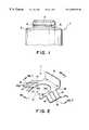
- FIG. 1is a front elevation of major part to show a shaftlike member used in the fixing structure according to an embodiment of the present invention
- FIG. 2is an overall perspective view to show a metal clip used in the fixing structure
- FIG. 3Ais a cross-sectional view along line 3 A— 3 A of FIG. 2;
- FIG. 3Bis a cross-sectional view along line 3 B— 3 B of FIG. 2;
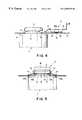
- FIG. 4is a longitudinal, cross-sectional view showing a state in which the panel is received by the receiving shoulder of the shaftlike member
- FIG. 5is a longitudinal, cross-sectional view showing a state in which the panel and the shaftlike member are fixed through the metal clip;
- FIG. 6is a top, cross-sectional view showing a state in which the panel and the shaftlike member are fixed through the metal clip.
- FIG. 7is a cross-sectional view to show another example of the metal clip.
- the present inventionwill be described in detail based on the preferred embodiment thereof illustrated.
- the fixing structure according to the embodimentis also predicated on the arrangement wherein a panel having a through hole, which is a mount member, and a shaftlike member such as a boss are fixed through a metal clip.
- the specific feature of the inventionis the employment of the following structure for the above shaftlike member and metal clip.
- the shaftlike member 1is basically constructed in the following structure as shown in FIG. 1 .
- the whole of the shaftlike member 1is molded of a resin material in a cylindrical shape having a desired size
- a head 2 to be inserted into the through hole of the panelis formed at the tip of the shaftlike member
- a receiving shoulder 3 having a larger diameter than that of the through hole of panelis formed a fixed distance apart below the head 2
- a step 4 to fit the through hole of the panelis formed on the top surface of the receiving shoulder 3
- an annular groove 5 with a small diameteris formed between the top surface of the step 4 and the bottom surface of the head 2 .
- the height of the step 4is greater than the thickness of the panel.
- the metal clip 11is constructed as shown in FIG. 2 and FIGS. 3A and 3B.
- a U-shaped slit 13 smaller than the head 2 but larger than the small-diameter groove 5is provided in an open shape in rectangular body 12 formed of an elastic metal sheet.
- Two elastic legs 14 for pushing two side pieces 12 a up away from the panel surface around the through holeare obliquely formed in a downwardly diverging state and are made integrally with the outer edges of the both side pieces 12 a defining the U-shaped slit 13 , the outer edges extending in the inserting direction of the clip.
- the tip portion 14 b of each elastic leg 14is folded back upward, and on each side only the folded edges are connected by connecting piece 15 .
- numeral 16denotes a gripper formed in a folded shape at the base portion of body 12 , and 17 stopper claws formed on the free end side of the both side pieces 12 a.
- the shaftlike member 1is also fixed to the panel P of the mount member in the following fashion.
- the head 2 of the shaftlike member 1is inserted into the through hole H of the panel P
- the panel Pis received by the receiving shoulder 3 with the larger diameter thereon as shown in FIG. 4 .
- the step 4is fitted in the through hole H of the panel P.
- the gripper 16is gripped with a tool or the like; and, while the portion of the small-diameter groove 5 of the shaftlike member 1 is made to face the U-shaped slit 13 of the metal clip 11 , the both side pieces 12 a are inserted into the small-diameter groove 5 , whereby the panel P and the shaftlike member 1 are also fixed through elasticity of the metal clip 11 .
- the elastic legs 14 for pushing the both side pieces 12 a up away from the surface of panel Pare provided at the outer edges of the both side pieces 12 a of the metal clip 11 as described previously, the free ends of the two side pieces 12 a can be inserted into the small-diameter groove 5 while the two side pieces 12 a are set largely away from the surface of panel P around the through hole H by the action of the elastic legs 14 .
- a rise amount of the two side pieces 12 ais adjusted by deflection of the elastic legs 14 in the inward or outward direction.
- each elastic leg 14can move smoothly on the surface of panel P without damaging the surface of panel P and can be deflected smoothly inward or outward. Since there are two elastic legs 14 each front and rear, the side pieces 12 a can be inserted into the small-diameter groove 5 in such a state that in the initial stage of insertion the front elastic legs 14 are mainly deflected and the body 12 is inclined forward. The structure of the invention thus facilitates the inserting work, also from this aspect.
- the panel Pcan be held for sure by the projection of the step 4 out of the surface of panel P. This prevents the panel P in the fixed state from undesirably shaking or prevents the hole edge of the panel P from riding over the step 4 and making the fixed state unstable, different from the conventional structure. Further, in the fixed state of the panel P, the stopper claws 17 bite into the peripheral surface of the head 2 , so that the metal clip 11 itself is prevented from slipping off from the shaftlike member 1 because of external force such as vibration.
- the present inventionis by no means limited to this structure.
- the present inventionmay optionally adopt such a structure that, as shown in FIG. 7, the tip portions of each elastic leg 14 are completely connected by connecting pieces 15 folded back upward and the turn center edges 15 a of the connecting pieces 15 are in contact with the surface of the panel P.
- this arrangementfurther improves the guiding property against the surface of the panel P and the deflecting property of the elastic legs 14 in the inward or outward direction.
- the present inventionpermits the free ends of the both side pieces to be inserted into the small-diameter groove of the shaftlike member while keeping the both side pieces of the metal clip the necessary rise amount above the surface of the mount member by the action of the elastic legs even if there is the burr or the like at the edge of the through hole in the mount member; whereby the free ends of the both side pieces can be inserted smoothly into the small-diameter groove of the shaftlike member without being caught by the burr or the like. Therefore, the inserting work of the both side pieces of the metal clip can be done well.
- the insertioncan be done by deflecting the elastic legs from the front elastic legs in the inserting direction to the rear end legs which make the operation more smooth. Also from this point, the present invention permits the inserting work to be done better.
- the turn center edges of the elastic legs or the connecting piecesare in contact with the surface of the mount member, and there is thus such an advantage that the movement and the inward or outward deflection of the elastic legs can be guided without strain and without damaging the surface of the mount member.
- the height of the step of the shaftlike member to fit the through hole of the mount memberis greater than the thickness of the mount member, whereby the mount member can be held for sure. This can prevent the mount member in the fixed state from undesirably shaking and prevent the edge of the through hole of the mount member from riding over the step and making the fixed state unstable. While the both side pieces of the metal clip are inserted into the small-diameter groove of the shaft member, the free ends of the both side pieces can be inserted into the small-diameter groove while keeping the both side pieces the necessary rise amount above the surface of the mount member by the action of the elastic legs.
- the free ends of the both side piecescan be inserted smoothly into the small-diameter groove without being caught even by the high step. Accordingly, the certainly fixed state is assured between the mount member and the shaftlike member and the inserting work of the both side pieces of the metal clip can be done well.
Landscapes
- Engineering & Computer Science (AREA)
- General Engineering & Computer Science (AREA)
- Mechanical Engineering (AREA)
- Clamps And Clips (AREA)
- Standing Axle, Rod, Or Tube Structures Coupled By Welding, Adhesion, Or Deposition (AREA)
- Snaps, Bayonet Connections, Set Pins, And Snap Rings (AREA)
Abstract
Description
Claims (2)
Applications Claiming Priority (2)
| Application Number | Priority Date | Filing Date | Title |
|---|---|---|---|
| JP9-085538 | 1997-03-21 | ||
| JP08553897AJP3252348B2 (en) | 1997-03-21 | 1997-03-21 | A fixing structure for fixing an attachment member having a metal clip and a through-hole and a shaft-shaped member via the metal clip |
Publications (1)
| Publication Number | Publication Date |
|---|---|
| US6305870B1true US6305870B1 (en) | 2001-10-23 |
Family
ID=13861666
Family Applications (1)
| Application Number | Title | Priority Date | Filing Date |
|---|---|---|---|
| US09/045,557Expired - LifetimeUS6305870B1 (en) | 1997-03-21 | 1998-03-20 | Metal clip and, fixing structure for fixing shaftlike member to mount member having through hole, with the metal clip |
Country Status (2)
| Country | Link |
|---|---|
| US (1) | US6305870B1 (en) |
| JP (1) | JP3252348B2 (en) |
Cited By (17)
| Publication number | Priority date | Publication date | Assignee | Title |
|---|---|---|---|---|
| US20030177618A1 (en)* | 2000-09-12 | 2003-09-25 | Yuichi Itou | Burglarproof retainer clip and method of manufacturing the retainer clip |
| US20060133909A1 (en)* | 2004-12-21 | 2006-06-22 | Stemco Lp | Keeper paddle |
| EP1691085A1 (en)* | 2005-02-10 | 2006-08-16 | Hamstra B.V. | Mounting assembly |
| US20070249224A1 (en)* | 2006-04-20 | 2007-10-25 | Won-Kyu Bang | Fixing structure of circuit board and display module comprising the same |
| WO2008074740A1 (en)* | 2006-12-19 | 2008-06-26 | Endress+Hauser Flowtec Ag | Device for measuring the volumetric or mass flow of a medium in a pipeline |
| US20100165592A1 (en)* | 2008-12-26 | 2010-07-01 | Fujitsu Limited | Attachment device and electronic apparatus |
| US20100232905A1 (en)* | 2009-03-13 | 2010-09-16 | Newfrey Llc | Joining stud and fastening arrangement |
| CN102811580A (en)* | 2011-05-31 | 2012-12-05 | 深圳富泰宏精密工业有限公司 | Gasket, connecting module applying same and sliding mechanism |
| US20130146409A1 (en)* | 2011-12-13 | 2013-06-13 | Akebono Corporation | Heat transfer preventer |
| US20140097202A1 (en)* | 2009-11-05 | 2014-04-10 | Joergen Knudsen | Support Unit |
| US20140119817A1 (en)* | 2012-11-01 | 2014-05-01 | Kindwin Opto Electronics (Shenzhen) Ltd. | Coaxial tensionable automatic lock |
| US9328535B2 (en) | 2014-01-17 | 2016-05-03 | Kwikset Corporation | Padlock cylinder retention |
| US20160169365A1 (en)* | 2014-12-15 | 2016-06-16 | Robert Bosch Gmbh | Handheld tool device |
| US20190074642A1 (en)* | 2015-05-08 | 2019-03-07 | Kathrein Werke Kg | HF Plug and Mounting Wall |
| CN109707913A (en)* | 2019-03-06 | 2019-05-03 | 无锡金尚汽车技术开发有限公司 | For installing the disconnecting prevention structure of hose coupling |
| US20230258236A1 (en)* | 2022-02-14 | 2023-08-17 | Sonnax Transmission Company | Solenoid stabilizers and methods for stabilizing solenoids in valve bodies |
| US20240026989A1 (en)* | 2021-06-24 | 2024-01-25 | Byd Company Limited | Electric valve |
Families Citing this family (2)
| Publication number | Priority date | Publication date | Assignee | Title |
|---|---|---|---|---|
| DE10049309C1 (en)* | 2000-10-04 | 2002-03-07 | Georg Fischer Schwab Gmbh | Water closet flush cistern pipe connection clip has pipe with abutment flanges engaging wall of cistern and circular clip |
| JP4762823B2 (en)* | 2006-08-04 | 2011-08-31 | 株式会社パイオラックス | Protection structure for automotive plastic parts |
Citations (29)
| Publication number | Priority date | Publication date | Assignee | Title |
|---|---|---|---|---|
| GB287753A (en)* | 1927-06-23 | 1928-03-29 | Johannes Wilhelm Hofmann | Improvements in or relating to electric insulator suspension devices |
| US2034559A (en)* | 1934-12-03 | 1936-03-17 | Wagner Electric Corp | Locking clip |
| US2244427A (en)* | 1938-08-18 | 1941-06-03 | Flex O Tube Company | Method of making fastening devices |
| US2278708A (en)* | 1939-01-17 | 1942-04-07 | Flex O Tube Company | Method of making fastening devices |
| US2487803A (en)* | 1947-08-21 | 1949-11-15 | Waldes Kohinoor Inc | Spring retaining ring |
| US2577748A (en)* | 1947-10-09 | 1951-12-11 | Borg Warner | Electrical connector |
| US2748906A (en)* | 1951-11-05 | 1956-06-05 | Tinnerman Products Inc | Fastening device |
| US2755698A (en)* | 1952-11-04 | 1956-07-24 | Waldes Kohinoor Inc | Retaining ring having shaft engaging projections to prevent inadvertent withdrawal |
| US3012744A (en)* | 1957-07-18 | 1961-12-12 | Waters Mfg Inc | Mounting device |
| US3178987A (en)* | 1962-10-16 | 1965-04-20 | Gen Motors Corp | Retainer clip |
| US3270124A (en)* | 1965-01-04 | 1966-08-30 | Ohio Brass Co | Electrical connector for suspension apparatus |
| US3302867A (en)* | 1965-10-23 | 1967-02-07 | Joseph T Roffy | Fan assembly |
| US3442171A (en)* | 1965-05-07 | 1969-05-06 | Fibora Ag | Unilaterally open safety clip |
| GB1288840A (en)* | 1969-10-30 | 1972-09-13 | ||
| US3867871A (en)* | 1973-04-26 | 1975-02-25 | Int Harvester Co | Piston-to-rod detachable connection |
| US3869179A (en)* | 1973-09-17 | 1975-03-04 | Caterpillar Tractor Co | Bracket and bolt-retaining means for tractor roller assemblies |
| US4113397A (en)* | 1975-10-17 | 1978-09-12 | Snyder Francis H | Pinless resilient coupling |
| WO1980002059A1 (en)* | 1979-03-23 | 1980-10-02 | Caterpillar Tractor Co | Keeper assembly |
| US4364685A (en)* | 1979-08-29 | 1982-12-21 | Gebr. Happich Gmbh | Device for attaching an insertion part to a base surface |
| US4593431A (en)* | 1984-03-14 | 1986-06-10 | Truth Incorporated | Snap stud |
| US4623050A (en)* | 1985-09-03 | 1986-11-18 | General Motors Corporation | Shoe hold-down pin and spring clip |
| US4735534A (en)* | 1987-01-12 | 1988-04-05 | Eaton Corporation | Fastener assembly for cylindrical opening |
| EP0326522A1 (en)* | 1988-01-28 | 1989-08-02 | EMBRU-WERKE, MANTEL & CIE | Connecting element for joining the side walls of a displayed body to the pillars of a space divider |
| US4951550A (en)* | 1987-10-30 | 1990-08-28 | Jidosha Kiki Co., Ltd. | Brake booster with key member having an elastic member |
| US5031511A (en)* | 1989-04-25 | 1991-07-16 | Valeo | Piston for an hydraulic brake, in particular for automotive vehicles |
| US5131894A (en)* | 1991-02-27 | 1992-07-21 | Dana Corporation | Axle shaft retainer of use in differential case |
| US5410899A (en)* | 1993-04-22 | 1995-05-02 | Tri/Mark Corporation | Retainer clip for escutcheon assembly |
| US5494368A (en)* | 1990-09-12 | 1996-02-27 | Matthews; Norman L. | Fastener |
| US5518332A (en)* | 1993-11-30 | 1996-05-21 | Nippon Cable System Inc. | End plate with clip |
- 1997
- 1997-03-21JPJP08553897Apatent/JP3252348B2/ennot_activeExpired - Lifetime
- 1998
- 1998-03-20USUS09/045,557patent/US6305870B1/ennot_activeExpired - Lifetime
Patent Citations (29)
| Publication number | Priority date | Publication date | Assignee | Title |
|---|---|---|---|---|
| GB287753A (en)* | 1927-06-23 | 1928-03-29 | Johannes Wilhelm Hofmann | Improvements in or relating to electric insulator suspension devices |
| US2034559A (en)* | 1934-12-03 | 1936-03-17 | Wagner Electric Corp | Locking clip |
| US2244427A (en)* | 1938-08-18 | 1941-06-03 | Flex O Tube Company | Method of making fastening devices |
| US2278708A (en)* | 1939-01-17 | 1942-04-07 | Flex O Tube Company | Method of making fastening devices |
| US2487803A (en)* | 1947-08-21 | 1949-11-15 | Waldes Kohinoor Inc | Spring retaining ring |
| US2577748A (en)* | 1947-10-09 | 1951-12-11 | Borg Warner | Electrical connector |
| US2748906A (en)* | 1951-11-05 | 1956-06-05 | Tinnerman Products Inc | Fastening device |
| US2755698A (en)* | 1952-11-04 | 1956-07-24 | Waldes Kohinoor Inc | Retaining ring having shaft engaging projections to prevent inadvertent withdrawal |
| US3012744A (en)* | 1957-07-18 | 1961-12-12 | Waters Mfg Inc | Mounting device |
| US3178987A (en)* | 1962-10-16 | 1965-04-20 | Gen Motors Corp | Retainer clip |
| US3270124A (en)* | 1965-01-04 | 1966-08-30 | Ohio Brass Co | Electrical connector for suspension apparatus |
| US3442171A (en)* | 1965-05-07 | 1969-05-06 | Fibora Ag | Unilaterally open safety clip |
| US3302867A (en)* | 1965-10-23 | 1967-02-07 | Joseph T Roffy | Fan assembly |
| GB1288840A (en)* | 1969-10-30 | 1972-09-13 | ||
| US3867871A (en)* | 1973-04-26 | 1975-02-25 | Int Harvester Co | Piston-to-rod detachable connection |
| US3869179A (en)* | 1973-09-17 | 1975-03-04 | Caterpillar Tractor Co | Bracket and bolt-retaining means for tractor roller assemblies |
| US4113397A (en)* | 1975-10-17 | 1978-09-12 | Snyder Francis H | Pinless resilient coupling |
| WO1980002059A1 (en)* | 1979-03-23 | 1980-10-02 | Caterpillar Tractor Co | Keeper assembly |
| US4364685A (en)* | 1979-08-29 | 1982-12-21 | Gebr. Happich Gmbh | Device for attaching an insertion part to a base surface |
| US4593431A (en)* | 1984-03-14 | 1986-06-10 | Truth Incorporated | Snap stud |
| US4623050A (en)* | 1985-09-03 | 1986-11-18 | General Motors Corporation | Shoe hold-down pin and spring clip |
| US4735534A (en)* | 1987-01-12 | 1988-04-05 | Eaton Corporation | Fastener assembly for cylindrical opening |
| US4951550A (en)* | 1987-10-30 | 1990-08-28 | Jidosha Kiki Co., Ltd. | Brake booster with key member having an elastic member |
| EP0326522A1 (en)* | 1988-01-28 | 1989-08-02 | EMBRU-WERKE, MANTEL & CIE | Connecting element for joining the side walls of a displayed body to the pillars of a space divider |
| US5031511A (en)* | 1989-04-25 | 1991-07-16 | Valeo | Piston for an hydraulic brake, in particular for automotive vehicles |
| US5494368A (en)* | 1990-09-12 | 1996-02-27 | Matthews; Norman L. | Fastener |
| US5131894A (en)* | 1991-02-27 | 1992-07-21 | Dana Corporation | Axle shaft retainer of use in differential case |
| US5410899A (en)* | 1993-04-22 | 1995-05-02 | Tri/Mark Corporation | Retainer clip for escutcheon assembly |
| US5518332A (en)* | 1993-11-30 | 1996-05-21 | Nippon Cable System Inc. | End plate with clip |
Cited By (29)
| Publication number | Priority date | Publication date | Assignee | Title |
|---|---|---|---|---|
| US20030177618A1 (en)* | 2000-09-12 | 2003-09-25 | Yuichi Itou | Burglarproof retainer clip and method of manufacturing the retainer clip |
| US6901638B2 (en)* | 2000-09-12 | 2005-06-07 | Thuou Hatujyo Kougyou Kabusiki Kaisya | Burglarproof retainer clip and method of manufacturing the retainer clip |
| US20060133909A1 (en)* | 2004-12-21 | 2006-06-22 | Stemco Lp | Keeper paddle |
| EP1691085A1 (en)* | 2005-02-10 | 2006-08-16 | Hamstra B.V. | Mounting assembly |
| US20070249224A1 (en)* | 2006-04-20 | 2007-10-25 | Won-Kyu Bang | Fixing structure of circuit board and display module comprising the same |
| US7364442B2 (en)* | 2006-04-20 | 2008-04-29 | Samsung Sdi Co., Ltd. | Fixing structure of circuit board and display module comprising the same |
| WO2008074740A1 (en)* | 2006-12-19 | 2008-06-26 | Endress+Hauser Flowtec Ag | Device for measuring the volumetric or mass flow of a medium in a pipeline |
| US20100165592A1 (en)* | 2008-12-26 | 2010-07-01 | Fujitsu Limited | Attachment device and electronic apparatus |
| US8085552B2 (en)* | 2008-12-26 | 2011-12-27 | Fujitsu Limited | Attachment device and electronic apparatus |
| US20100232905A1 (en)* | 2009-03-13 | 2010-09-16 | Newfrey Llc | Joining stud and fastening arrangement |
| US20140097202A1 (en)* | 2009-11-05 | 2014-04-10 | Joergen Knudsen | Support Unit |
| US8453299B2 (en)* | 2011-05-31 | 2013-06-04 | Shenzhen Futaihong Precision Industry Co., Ltd. | Connecting module and sliding mechanism for electronic device |
| CN102811580A (en)* | 2011-05-31 | 2012-12-05 | 深圳富泰宏精密工业有限公司 | Gasket, connecting module applying same and sliding mechanism |
| US20120308296A1 (en)* | 2011-05-31 | 2012-12-06 | Fih (Hong Kong) Limited | Conncting module and sliding mechanism for electronic device |
| US20130146409A1 (en)* | 2011-12-13 | 2013-06-13 | Akebono Corporation | Heat transfer preventer |
| US9267557B2 (en)* | 2011-12-13 | 2016-02-23 | Akebono Brake Corporation | Heat transfer preventer |
| US20140119817A1 (en)* | 2012-11-01 | 2014-05-01 | Kindwin Opto Electronics (Shenzhen) Ltd. | Coaxial tensionable automatic lock |
| US9194415B2 (en)* | 2012-11-01 | 2015-11-24 | Kindwin Opto Electronic (Shenzhen) Co., Ltd. | Coaxial tensionable automatic lock |
| US10012010B2 (en) | 2014-01-17 | 2018-07-03 | Spectrum Brands, Inc. | Padlock cylinder retention |
| US9328535B2 (en) | 2014-01-17 | 2016-05-03 | Kwikset Corporation | Padlock cylinder retention |
| US20160169365A1 (en)* | 2014-12-15 | 2016-06-16 | Robert Bosch Gmbh | Handheld tool device |
| US10746277B2 (en)* | 2014-12-15 | 2020-08-18 | Robert Bosch Gmbh | Handheld tool device with bracket holder unit for connection of two gear housings |
| US11333237B2 (en)* | 2014-12-15 | 2022-05-17 | Robert Bosch Gmbh | Handheld tool device |
| US20190074642A1 (en)* | 2015-05-08 | 2019-03-07 | Kathrein Werke Kg | HF Plug and Mounting Wall |
| CN109707913A (en)* | 2019-03-06 | 2019-05-03 | 无锡金尚汽车技术开发有限公司 | For installing the disconnecting prevention structure of hose coupling |
| US20240026989A1 (en)* | 2021-06-24 | 2024-01-25 | Byd Company Limited | Electric valve |
| US12379043B2 (en)* | 2021-06-24 | 2025-08-05 | Byd Company Limited | Electric valve |
| US20230258236A1 (en)* | 2022-02-14 | 2023-08-17 | Sonnax Transmission Company | Solenoid stabilizers and methods for stabilizing solenoids in valve bodies |
| US12188525B2 (en)* | 2022-02-14 | 2025-01-07 | Sonnax Transmission Company | Solenoid stabilizers and methods for stabilizing solenoids in valve bodies |
Also Published As
| Publication number | Publication date |
|---|---|
| JP3252348B2 (en) | 2002-02-04 |
| JPH10267016A (en) | 1998-10-06 |
Similar Documents
| Publication | Publication Date | Title |
|---|---|---|
| US6305870B1 (en) | Metal clip and, fixing structure for fixing shaftlike member to mount member having through hole, with the metal clip | |
| US5573362A (en) | Fastener including elastic legs for retaining the fastener in a mounting hole | |
| US7891926B2 (en) | Fastener | |
| JP2719006B2 (en) | Push-in fasteners | |
| US4237587A (en) | Paper clip | |
| EP1179307B1 (en) | Cord clip | |
| US6389658B1 (en) | Clip for mounting objects on a wall stud | |
| US6477744B1 (en) | Visor clip | |
| KR970059516A (en) | The connection of the valve body | |
| US20020017800A1 (en) | Sun visor holder | |
| JPH0550275U (en) | Locking part structure for bolt locking | |
| EP0682186A1 (en) | Member mounting clip | |
| US4070945A (en) | Screw grommet | |
| JPH0763206A (en) | Lengthy object installation tool | |
| JPH04109129U (en) | Metal welding studs and plastic clips | |
| JPH0331925B2 (en) | ||
| JPH07190030A (en) | Retainer clip | |
| JP2010104442A (en) | Mirror attaching structure for mirror cabinet | |
| JPH11280726A (en) | Escape-preventive clip | |
| JP3554591B2 (en) | Band clip for mounting long objects | |
| JP2555280Y2 (en) | Pipe end protection cap | |
| JPH0680014U (en) | clip | |
| JPH0842536A (en) | clip | |
| JPH1030622A (en) | Fastener | |
| JP2000323870A (en) | Spacer for printed substrate |
Legal Events
| Date | Code | Title | Description |
|---|---|---|---|
| AS | Assignment | Owner name:HONDA GIKEN KOGYO KABUSHIKI KAISHA, JAPAN Free format text:ASSIGNMENT OF ASSIGNORS INTEREST;ASSIGNORS:MITA, KAZUHIRO;SASAGAWA, SATORU;REEL/FRAME:009058/0650;SIGNING DATES FROM 19980302 TO 19980317 Owner name:PIOLAX INC., JAPAN Free format text:ASSIGNMENT OF ASSIGNORS INTEREST;ASSIGNORS:MITA, KAZUHIRO;SASAGAWA, SATORU;REEL/FRAME:009058/0650;SIGNING DATES FROM 19980302 TO 19980317 | |
| STCF | Information on status: patent grant | Free format text:PATENTED CASE | |
| FEPP | Fee payment procedure | Free format text:PAYOR NUMBER ASSIGNED (ORIGINAL EVENT CODE: ASPN); ENTITY STATUS OF PATENT OWNER: LARGE ENTITY | |
| FPAY | Fee payment | Year of fee payment:4 | |
| FPAY | Fee payment | Year of fee payment:8 | |
| AS | Assignment | Owner name:STEERING SOLUTIONS IP HOLDING CORPORATION, MICHIGA Free format text:ASSIGNMENT OF ASSIGNORS INTEREST;ASSIGNORS:PACIFIC CENTURY MOTORS, INC.;NEXTEER (BEIJING) TECHNOLOGY CO., LTD.;REEL/FRAME:027870/0666 Effective date:20120126 | |
| FPAY | Fee payment | Year of fee payment:12 |