US6305848B1 - High density optoelectronic transceiver module - Google Patents
High density optoelectronic transceiver moduleDownload PDFInfo
- Publication number
- US6305848B1 US6305848B1US09/595,671US59567100AUS6305848B1US 6305848 B1US6305848 B1US 6305848B1US 59567100 AUS59567100 AUS 59567100AUS 6305848 B1US6305848 B1US 6305848B1
- Authority
- US
- United States
- Prior art keywords
- optical
- blindmate
- density
- assemblies
- optoelectronic module
- Prior art date
- Legal status (The legal status is an assumption and is not a legal conclusion. Google has not performed a legal analysis and makes no representation as to the accuracy of the status listed.)
- Expired - Lifetime
Links
Images


Classifications
- G—PHYSICS
- G02—OPTICS
- G02B—OPTICAL ELEMENTS, SYSTEMS OR APPARATUS
- G02B6/00—Light guides; Structural details of arrangements comprising light guides and other optical elements, e.g. couplings
- G02B6/24—Coupling light guides
- G02B6/42—Coupling light guides with opto-electronic elements
- G02B6/4292—Coupling light guides with opto-electronic elements the light guide being disconnectable from the opto-electronic element, e.g. mutually self aligning arrangements
- G—PHYSICS
- G02—OPTICS
- G02B—OPTICAL ELEMENTS, SYSTEMS OR APPARATUS
- G02B6/00—Light guides; Structural details of arrangements comprising light guides and other optical elements, e.g. couplings
- G02B6/24—Coupling light guides
- G02B6/42—Coupling light guides with opto-electronic elements
- G02B6/4201—Packages, e.g. shape, construction, internal or external details
- G02B6/4246—Bidirectionally operating package structures
- G—PHYSICS
- G02—OPTICS
- G02B—OPTICAL ELEMENTS, SYSTEMS OR APPARATUS
- G02B6/00—Light guides; Structural details of arrangements comprising light guides and other optical elements, e.g. couplings
- G02B6/24—Coupling light guides
- G02B6/42—Coupling light guides with opto-electronic elements
- G02B6/43—Arrangements comprising a plurality of opto-electronic elements and associated optical interconnections
- G—PHYSICS
- G02—OPTICS
- G02B—OPTICAL ELEMENTS, SYSTEMS OR APPARATUS
- G02B6/00—Light guides; Structural details of arrangements comprising light guides and other optical elements, e.g. couplings
- G02B6/24—Coupling light guides
- G02B6/36—Mechanical coupling means
- G02B6/38—Mechanical coupling means having fibre to fibre mating means
- G02B6/3807—Dismountable connectors, i.e. comprising plugs
- G02B6/3873—Connectors using guide surfaces for aligning ferrule ends, e.g. tubes, sleeves, V-grooves, rods, pins, balls
- G02B6/3882—Connectors using guide surfaces for aligning ferrule ends, e.g. tubes, sleeves, V-grooves, rods, pins, balls using rods, pins or balls to align a pair of ferrule ends
- G—PHYSICS
- G02—OPTICS
- G02B—OPTICAL ELEMENTS, SYSTEMS OR APPARATUS
- G02B6/00—Light guides; Structural details of arrangements comprising light guides and other optical elements, e.g. couplings
- G02B6/24—Coupling light guides
- G02B6/36—Mechanical coupling means
- G02B6/38—Mechanical coupling means having fibre to fibre mating means
- G02B6/3807—Dismountable connectors, i.e. comprising plugs
- G02B6/3897—Connectors fixed to housings, casing, frames or circuit boards
- G—PHYSICS
- G02—OPTICS
- G02B—OPTICAL ELEMENTS, SYSTEMS OR APPARATUS
- G02B6/00—Light guides; Structural details of arrangements comprising light guides and other optical elements, e.g. couplings
- G02B6/24—Coupling light guides
- G02B6/42—Coupling light guides with opto-electronic elements
- G02B6/4201—Packages, e.g. shape, construction, internal or external details
- G02B6/4249—Packages, e.g. shape, construction, internal or external details comprising arrays of active devices and fibres
Definitions
- the present inventionrelates to a high-density blindmate optoelectronic module and mating optical connector.
- the high-density blindmate optoelectronic moduleis particularly well suited for use in high capacity optical network assemblies, such as optical routers, Dense Wavelength Division Multiplexed (DWDM) transmission equipment, and optical cross connects.
- DWDMDense Wavelength Division Multiplexed
- FIG. 1A simplified perspective view of a typical prior art chassis based system is shown in FIG. 1 .
- the chassis based system 100includes a rack 102 comprising a plurality of tracks 104 extending perpendicularly from a backplane 106 .
- the rack 102is configured to receive a plurality of printed circuit boards 108 .
- the printed circuit boards 108may be inserted into tracks 104 and mated with connectors 110 mounted on the backplane 106 .
- Most such assembliesinclude racks for receiving large numbers of removable printed circuit boards.
- the backplane 106is configured to route signals between various optical and/or electrical circuits formed on the circuit boards 108 inserted into the rack.
- the backplane 106may include embedded optical fibers for carrying optical signals, conductive traces for carrying electrical signals, or some combination of both optical fibers and conductive traces for handling both optical and electrical signals.
- the optical and/or electrical circuits on the backplanecouple signals between various points within the chassis based system, and may perform additional functions such as amplifying, splitting or multiplexing signals. Signals may be routed between printed circuit boards, or to different points on the same circuit board.
- the interface between the printed circuit boards 108 and the backplane 106is formed along the rear edge of the printed circuit boards as the boards are inserted into the rack.
- the interfaceis formed by the act of inserting the printed circuit board into the rack. This is known in the art as a blindmate connection because the connector components that form the interface align and mate of their own accord when the printed circuit board is installed in the rack and the interface occurs within the rack, away from the technician installing the printed circuit board.
- the signal interfacemust automatically couple each signal that is to be transmitted from the printed circuit board to the appropriate backplane circuit, be it an optical fiber or a conductive circuit trace.
- each signal originating from the backplane and destined for a circuit formed on the circuit boardmust also be properly coupled with the correct circuit elements on the printed circuit board. All of this must be achieved by the simple act of inserting the printed circuit board into the rack.
- the necessity of providing a blindmate connection between the removable circuit boards and the backplaneposes significant difficulties for creating an optical interface capable of handling a large number of optical signals.
- the current generation of optoelectronic assembliesuse fiber-optic connectors mounted on both the backplane and along the rear edge of the removable printed circuit boards. Fiber-optic connectors employed for this purpose may use single fiber connector ferrules or multi-fiber connector ferrules.
- optoelectronic moduleswill be mounted on the surface of a printed circuit board and optical fiber jumpers will be installed between the transceivers and the optical connectors mounted on the edge of the circuit board. The jumpers carry the optical signals emitted from the optical transmitters to the optical connector or from the connector to the optical receivers mounted elsewhere on the printed circuit board.
- a problem with this arrangementis that the optical transmitters and receivers (commonly referred to together as transceivers) take up a great deal of real estate on the printed circuit board, occupying space which could otherwise be dedicated to other purposes and provide additional functionality to the printed circuit board. Also, installing the optical fiber jumpers between the transceiver elements and the connector interface is time-consuming and expensive. The additional jumper attenuates the optical signal and adds to the cost.
- such a high-density blindmate optoelectronic modulewill include optical transmitters and receivers mounted directly within the module.
- the transceiver componentswill be arranged so that optical signals both transmitted and received by the module may be coupled directly to the backplane of a chassis based system, and the interface between the module and the backplane connector will form a blindmate optical connection whereby the high-density blindmate optoelectronic module is coupled to the backplane by sliding the printed circuit board on which the module is mounted into the chassis based system's support rack.
- a high-density blindmate optoelectronic moduleoccupy as little space as possible on the printed circuit board. It is also desirable that signals be directly coupled between the module's optical interface and the backplane without the need for optical fiber jumpers. Finally, it is also desirable that a high-density optoelectronic interface module have improved heat dissipation characteristics to protect the transceiver components within the module.
- the present inventionprovides a high-density blindmate optoelectronic module.
- the moduleis adapted to be mounted along the rearward edge of a printed circuit board which is configured to be inserted into a rack support system within a chassis based system such as a network of routers, DWDM transmission equipment, optical cross connects, or other optoelectronic assemblies.
- each mother boardmay have additional components mounted on separate “daughter” cards that are interconnected with the circuits formed on the mother boards.
- the high-density blindmate optoelectronic moduleis configured to quickly and accurately mate with the various circuits of a mother board. Further, the high-density blindmate optoelectronic module is adapted to blindmate with an optical connector mounted on the backplane of the chassis based system as the mother board is inserted into the support rack. Alignment structures within the high-density blindmate optoelectronic module act to align the optical signals emitted from the optical transmitting elements to optical fibers supported within the mating optical connector mounted on the backplane. Likewise, the optical signals carried by optical fibers within the backplane and terminating within the backplane mounted optical connector are aligned with optical receiver components within the high-density blindmate optoelectronic module.
- a high-density blindmate optoelectronic modulecomprises a transceiver mounting block.
- a plurality of daughter cardsare mounted side by side within the transceiver mounting block.
- One or more optical transmitters, optical receivers, or combination of transmitters and receiversare mounted within the connectorized optical sub-assembly contained on each daughter card. Because density is critical, daughter cards are mounted perpendicular to the motherboard in a configuration that allows substantial increases in optical channel density.
- a pair of fine alignment pinsprotrude from a front surface of each connectorized optical sub-assembly and a pair of coarse alignment pins protrude from the transceiver mounting block.
- Optical transmitters mounted within the connectorized optical sub-assemblyare positioned such that the light signals emitted by the transmitters are directed along optical axes that are precisely oriented relative to the output dimensions of the connectorized optical sub-assembly and extend through the front surface of the connectorized optical sub-assembly.
- optical receivers mounted within the connectorized optical sub-assemblyare positioned such that precision oriented optical signals received from the backplane side of the optical interface are directed to the appropriate photosensitive components of the receivers.
- the high-density blindmate optoelectronic moduleis configured to blindmate with a similarly constructed fiber-optic connector.
- the fiber-optic connectorsupports a plurality of optical fibers which, when connected with the high-density blindmate optoelectronic module, are precisely aligned with the optical axes of the transmitter and receiver components mounted within the connectorized optical sub-assemblies.
- the mating connectorincludes alignment bores for receiving the coarse alignment pins extending from the high-density transceiver module's transceiver mounting block. As the module is moved closer toward the fully connected position, the fine alignment pins protruding from the connectorized optical sub-assemblies engage fine alignment bores formed within multi-fiber connector ferrules within the mating connector.
- Each connectorized optical sub-assemblyis mounted to a corresponding daughter card.
- the daughter cardsprovide the electronic circuitry for driving the optical transmitters and processing the data signals received by the optical receivers mounted within the connectorized optical sub-assemblies.
- the transceiver blocksare attached to the daughter cards by way of electrical leads extending from the rear of the connectorized optical sub-assemblies. The electrical leads are soldered to circuit components formed on surfaces of the daughter cards.
- the circuitry contained on each of the daughter cardscan be customized to fit the particular arrangement of transmitters and/or receivers mounted within each transceiver block.
- Each connectorized optical sub-assembly and daughter card assemblyis inserted into the transceiver mounting block, with the front end of each connectorized optical sub-assembly protruding through the apertures formed in the transceiver mounting block.
- the daughter cardsextend parallel to one another out the back end of the transceiver mounting block.
- the mounting blockis thermally connected to each daughter card, which allows it to act as a heat sink.
- the mounting blockalso provides mechanical support to each daughter card and connectorized optical sub-assembly.
- the daughter cards and connectorized optical sub-assembliesare mounted in a perpendicular fashion to the motherboard, signals coming from the motherboard and going to the top laser, and coming from the top photodiode to the motherboard, will have a longer path than the bottom laser and photodiodes.
- the optical connection between a transmitter array and a receiver arrayis laid out so that the shortest signal path on the transmitter side is connected to the longest signal path on the receiver side.
- each laseris matched with a complementary receiver to ensure constant channel to channel signal path length.
- Each daughter cardincludes connector pins configured to mate with circuit elements formed on a mother board.
- the connector pinsmay be press fit into conductive vias formed on the mother board, or the pins may be soldered to solder pads formed on the surface of the mother boards.
- the connector pinssecure and electrically connect the daughter boards, and therefore the high-density blindmate optoelectronic module itself, to the mother board.
- the circuits connected to the connector pinsinclude the operating voltages for the transceiver components, as well as the signals to be transmitted from the lasers and the signals received from the photodiodes.
- FIG. 1is a simplified perspective view of a typical chassis based system
- FIG. 2is a perspective view of a high-density blindmate optoelectronic module according to the present invention, along with a mating fiber-optic connector seen from the rear;
- FIG. 3is a perspective view of the front of the mating fiber-optic connector of FIG. 2;
- FIG. 4is a perspective cross section view of an connectorized optical sub-assembly employed in a high-density blindmate optoelectronic module according to the present invention
- FIG. 5is a perspective view of an connectorized optical sub-assembly connected to a daughter card
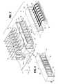
- FIG. 6is a cut-away perspective view of the high-density blindmate optoelectronic module shown in FIG. 1;
- FIG. 7is a perspective view of a high-density blindmate optoelectronic module according to an embodiment of the invention.
- a high-density blindmate optoelectronic moduleaccording to the present invention is a shown at 10 .
- the high-density blindmate optoelectronic moduleis configured to mount on the rear edge of mother board 14 .
- Mother board 14is itself configured to mount within a printed circuit board support rack within an chassis based system similar to that described in the Background of the Invention section of this specification and shown in FIG. 1 .
- Also depicted in FIG. 2is a mating optical connector 12 .
- the high-density blindmate optoelectronic module 10is configured to interface with the mating optical connector 12 .
- the mating optical connector 12will be mounted on the backplane of a chassis based system in place of the connector 110 shown in FIG. 1 .
- the mating optical connector 12may be joined to an optical fabric such as the optical fabric 52 shown in the drawing.
- the mating optical connector 12itself must be rigidly mounted within the chassis based system in order to receive the connecting portion of the high-density blindmate optoelectronic module 10 as the mother board 14 is inserted into the printed circuit board support rack of the chassis based system.
- optical signals emitted from optical transmitters within the high-density blindmate optoelectronic module 10are coupled to optical fibers mounted within the mating optical connector 12 .
- optical signals originating from elsewhere within the chassis based system and carried by optical fibers within the backplane or fabric 52are coupled from the mating optical connector 12 to optical receivers mounted in the high-density blindmate optoelectronic module 10 .
- the high-density blindmate optoelectronic module 10comprises a transceiver mounting block 16 which defines a plurality of apertures 18 . Each of the apertures 18 is configured to receive a connectorized optical sub-assembly 28 .
- a single connectorized optical sub-assembly 28is shown in cross section in FIG. 4.
- a pair of optical transmitters 60 , 62 and a pair of optical receivers 64 , 66are shown in block form mounted within a cavity 67 , formed within the connectorized optical sub-assembly 28 .
- Optical transmitters 60 , 62are positioned within the connectorized optical sub-assembly so as to emit an optical signal along a precisely defined optical axis that extends outward through the front surface 74 of the connectorized optical sub-assembly 28 .
- the optical receivers 64 , 66are positioned to receive optical signals directed along optical axes which are precisely located relative to the outer dimensions of the connectorized optical sub-assembly 28 .
- Electrical leads 84(see FIG. 4) connect to the transmitter and receiver components and extend through the back end of the connectorized optical sub-assembly 28 .
- a connectorized optical sub-assembly 28could be formed having optical transmitters only or optical receivers only. Or, a connectorized optical sub-assembly may have any combination of transmitters and receivers. Also, the total number of transceiver components mounted within the connectorized optical sub-assembly 28 is not limited to four. Any number of transmitters and/or receivers could be mounted within a connectorized optical sub-assembly, the total number of components being limited only by the size of sub-assembly.
- Most embodimentswill have either 4, 8, or 12 transmitting and/or receiving components within each connectorized optical sub-assembly. This is due to the fact that most fiber-optic connectors, such as optical connector 12 , are designed to have multi-fiber connector ferrules that support up to 12 optical fibers per ferrule. In the event that optical connectors are developed having a greater number of optical fibers mounted within the connector ferrules, it is contemplated that connectorized optical sub-assemblies 28 incorporated in the high-density blindmate optoelectronic module 10 of the present invention could be produced having a number of transceiver components equal to the number of fibers supported by any newly developed connector ferrules.
- a single connectorized optical sub-assembly 28is shown mounted to a daughter card 20 .
- the electrical leads 84 extending from the back end of the connectorized optical sub-assembly 28are soldered to solder pads 72 formed on a surface of the daughter card 20 .
- the daughter card 20contains circuitry and components for driving the optical transmitters and for processing signals received by the optical receivers housed within the connectorized optical sub-assembly 28 .
- the signals for driving transmitters 60 , 62 and the signals received by receivers 64 , 66are coupled between the daughter card 20 and the transceiver components within connectorized optical sub-assembly 28 through solder pads 72 and electrical leads 84 (see FIG. 4 ).
- Daughter card 20further includes a plurality of contact pins 22 .
- a plurality of connectorized optical sub-assemblies 28are inserted into the apertures 18 formed in the transceiver mounting block 16 .
- the daughter cards 20protrude from the back end of the transceiver mounting block 16 .
- the plurality of connectorized optical sub-assemblies 28maintain a thermal connection with the transceiver mounting block 16 .
- the transceiver mounting blockhas heat dissipation features which allow it to remove heat from the connectorized optical sub-assemblies 28 and circuit elements located on the daughter cards 20 . This helps to cool the optical sub-assemblies and circuits, protecting them and increasing their useful life.
- the transceiver mounting block 16is surrounded by an outer connector shroud 17 . Though not shown in the drawing, a mounting collar may be provided around the outer shroud 17 . These features secure the assembly to the back-edge of the mother board. Since the high-density blindmate optoelectronic module 10 is mounted on the motherboard 14 and the mother board is inserted into a fixed track, a small degree of movement of the mating connector 12 in the X and Y directions is required to allow the connector 12 to properly align itself with the module 10 .
- a spring or other biasing membermay be included within the mating optical connector 12 to bias the interface in the forward Z direction to ensure a tight fit between the front surfaces 74 of the connectorized optical sub-assemblies and the front surfaces 45 of the connector ferrules formed within mating connector 12 .
- the X, Y, and Z floatmay be provided in the high-density blindmate optoelectronic module 10 , rather than on the mating optical connector 12 .
- the high-density blindmate optoelectronic module 10is to be mounted along the rear edge of mother board 14 .
- One method for connecting the module 10 to the mother board 14is a press fit connection between the contact pins 22 protruding from daughter boards 20 and the mother board 14 .
- conductive contact vias 24are formed within the mother board 14 , corresponding to the locations of the contact pins 22 .
- the dimensions of the contact pins 22are closely matched to the vias 24 .
- a small presscan then be used to force the contact pins 22 into the contact vias 24 .
- the compression fit between the contact pins 22 and vias 24acts to secure the high-density blindmate optoelectronic module 10 to the mother board 14 , and provides the electrical connection between the circuits on the mother board 14 and the daughter cards 20 .
- Alternative mounting strategiesinclude soldering the contact pins 22 within vias 24 , using surface mount technologies for securing and connecting the daughter cards 20 to the mother board 14 , or using a press fit card-edge connector such as the BPS interface from Molex, Inc.
- Mother board 14is adapted to be inserted into the printed circuit board support rack of an chassis based system with the high-density blindmate optoelectronic module 10 mounted along the rear edge of the mother board facing the backplane of the chassis based system.
- the high-density blindmate optoelectronic module 10When mounted in this way, the high-density blindmate optoelectronic module 10 is positioned to blindmate with the mating optical connector 12 , which is mounted either directly on the backplane of the chassis based system or rigidly attached somewhere within the chassis based system. By inserting the mother board 14 into the chassis based system, the high-density blindmate optoelectronic module 10 engages the mating optical connector 12 , thereby forming the interface between the module 10 and the backplane or optical fabric 52 .
- the blindmate connection between the high-density blindmate optoelectronic module 10 and the fiber-optic connector 12occurs as the mother board 14 is inserted into the printed circuit board support rack as follows. As the mother board 14 is inserted into the printed circuit board support rack, the rear edge of the mother board 14 approaches the backplane. The high-density blindmate optoelectronic module 10 mounted along the rear edge of the mother board 14 is brought towards the mating optical connector 12 . When the module 10 reaches the fiber-optic connector 12 , the coarse alignment pins 32 protruding from the transceiver support block 16 engage coarse alignment bores 44 formed in the mating optical connector 12 .
- the position of the high-density blindmate optoelectronic module 10is adjusted in the X and Y directions by the interaction of the coarse alignment pins 32 with the coarse alignment bores 44 .
- the coarse alignment between the high-density blindmate optoelectronic module 10 and the mating optical connector 12ensures that, as the mother board 14 is inserted further into the printed circuit board support rack, the fine alignment pins 30 protruding from the front surface 74 of each of the connectorized optical sub-assemblies 28 , will engage the fine alignment bores 43 formed in the fiber support ferrules 42 within the mating optical connector 12 .
- the front surfaces 74 of the connectorized optical sub-assemblies 28will abut and be biased against the front surfaces 45 of the connector ferrules 42 within optical connector 12 .
- optical fibers 47 supported within the connector ferrule 42will be aligned with the optical axes of the optical transmitters and optical receivers mounted within the connectorized optical sub-assemblies 28 of the high-density blindmate optoelectronic module 10 , and optical signal may be coupled therebetween.
- FIG. 7An alternate embodiment of a high-density blindmate optoelectronic module according to the present invention is shown in FIG. 7 .
- This embodimentis substantially the same as that shown in FIG. 2, except that the coarse alignment pins 32 (FIG. 2) have been removed and an alignment clip 132 has been attached over the outer shroud 17 .
- Circular bosses 134protrude from the shroud 17 to engage alignment apertures 136 formed in the clip 132 .
- Bosses 134 and apertures 136align the clip with the module and act to hold the clip in place.
- Lateral alignment fingers 138extend forwardly from the sides of clip 132 . Fingers 138 are slightly flexible and have angled hook-like surfaces 140 at their distal ends.
- the fingers 138engage slots 142 formed on the mating optical connector 12 when the module 10 is mated with connector 12 .
- the interaction of the fingers 138 and slots 142provide coarse lateral alignment of the module 10 with the connector 12 .
- Coarse vertical alignmentis less critical due to the position of the module 10 on the mother board 14 .
- the vertical position of the mother boardis fixed by the tracks into which the motherboard is being inserted. Nonetheless, a plurality of small tabs 139 extend forwardly from the upper and lower sides of the clip 132 . The tabs 139 ensure that the module 10 mates vertically with the connector 12 .
- the fingersflex inward such that the ridges 144 engage the lips 146 to secure the module 10 to connector 12 .
Landscapes
- Physics & Mathematics (AREA)
- General Physics & Mathematics (AREA)
- Optics & Photonics (AREA)
- Optical Couplings Of Light Guides (AREA)
Abstract
Description
Claims (19)
Priority Applications (3)
| Application Number | Priority Date | Filing Date | Title |
|---|---|---|---|
| US09/595,671US6305848B1 (en) | 2000-06-19 | 2000-06-19 | High density optoelectronic transceiver module |
| PCT/US2001/007636WO2002001269A1 (en) | 2000-06-19 | 2001-03-09 | High density optoelectronic transceiver module |
| AU2001249136AAU2001249136A1 (en) | 2000-06-19 | 2001-03-09 | High density optoelectronic transceiver module |
Applications Claiming Priority (1)
| Application Number | Priority Date | Filing Date | Title |
|---|---|---|---|
| US09/595,671US6305848B1 (en) | 2000-06-19 | 2000-06-19 | High density optoelectronic transceiver module |
Publications (1)
| Publication Number | Publication Date |
|---|---|
| US6305848B1true US6305848B1 (en) | 2001-10-23 |
Family
ID=24384186
Family Applications (1)
| Application Number | Title | Priority Date | Filing Date |
|---|---|---|---|
| US09/595,671Expired - LifetimeUS6305848B1 (en) | 2000-06-19 | 2000-06-19 | High density optoelectronic transceiver module |
Country Status (3)
| Country | Link |
|---|---|
| US (1) | US6305848B1 (en) |
| AU (1) | AU2001249136A1 (en) |
| WO (1) | WO2002001269A1 (en) |
Cited By (117)
| Publication number | Priority date | Publication date | Assignee | Title |
|---|---|---|---|---|
| US6431765B1 (en)* | 1999-06-11 | 2002-08-13 | Cisco Technology Inc. | Distributed network repeater module and method |
| US20020181896A1 (en)* | 2001-06-04 | 2002-12-05 | Mcclellan Brian J. | Telecommunications chassis and module |
| US6497518B1 (en)* | 2000-11-14 | 2002-12-24 | National Semiconductor Corporation | Miniature opto-electronic transceiver |
| US20030026556A1 (en)* | 2001-08-03 | 2003-02-06 | National Semiconductor Corporation | Optical sub-assembly for optoelectronic modules |
| US6527588B2 (en)* | 1997-01-16 | 2003-03-04 | Fci Americas Technology, Inc. | Electrical connector with integrated PCB assembly |
| US20030057535A1 (en)* | 2001-09-24 | 2003-03-27 | National Semiconductor Corporation | Techniques for attaching rotated photonic devices to an optical sub-assembly in an optoelectronic package |
| US6547445B2 (en) | 2001-02-06 | 2003-04-15 | Teradyne, Inc. | High-density fiber optic backplane |
| US20030087505A1 (en)* | 2000-11-14 | 2003-05-08 | Peter Deane | Method and apparatus for adapting a miniature form-factor connector to a standard format fiber optic connector plug |
| US6565384B2 (en)* | 2000-10-26 | 2003-05-20 | Framatome Connectors International | Electro-optical connector with flexible circuit |
| US20030165303A1 (en)* | 2000-05-09 | 2003-09-04 | National Semiconductor Corporation, A Delaware Corporation | Ceramic optical sub-assembly for opto-electronic module utilizing LTCC ( low-temperature co-fired ceramic ) technology |
| EP1343039A1 (en)* | 2002-03-08 | 2003-09-10 | Agilent Technologies, Inc. - a Delaware corporation - | Optoelectronic module |
| US6623177B1 (en)* | 2001-07-09 | 2003-09-23 | Emc Corporation | Systems and methods for providing fiber optic communications between circuit boards |
| US6624507B1 (en) | 2000-05-09 | 2003-09-23 | National Semiconductor Corporation | Miniature semiconductor package for opto-electronic devices |
| US6642613B1 (en) | 2000-05-09 | 2003-11-04 | National Semiconductor Corporation | Techniques for joining an opto-electronic module to a semiconductor package |
| US20030221706A1 (en)* | 2002-05-29 | 2003-12-04 | Sepehr Kiani | Methods and apparatus for cleaning optical connectors |
| US20040052472A1 (en)* | 2002-09-13 | 2004-03-18 | Roth Richard F. | Techniques for forming fiber optic connections in a modularized manner |
| US20040086250A1 (en)* | 2002-11-01 | 2004-05-06 | Frank Loh | Dense wavelength division multiplexer module |
| US20040125366A1 (en)* | 2002-12-26 | 2004-07-01 | Sepehr Kiani | Systems and methods for inspecting an optical interface |
| US6762941B2 (en) | 2002-07-15 | 2004-07-13 | Teradyne, Inc. | Techniques for connecting a set of connecting elements using an improved latching apparatus |
| US20040141709A1 (en)* | 2000-12-26 | 2004-07-22 | Anderson Gene R. | Attenuator and conditioner |
| US6798965B2 (en)* | 2000-06-02 | 2004-09-28 | Confluent Photonics Corporation | Low loss fiber optic jumper with electronic presence detection |
| US6799902B2 (en)* | 2000-12-26 | 2004-10-05 | Emcore Corporation | Optoelectronic mounting structure |
| US20050013581A1 (en)* | 2003-07-15 | 2005-01-20 | National Semiconductor Corporation | Multi-purpose optical light pipe |
| US20050013560A1 (en)* | 2003-07-15 | 2005-01-20 | National Semiconductor Corporation | Opto-electronic module form factor having adjustable optical plane height |
| US6863444B2 (en) | 2000-12-26 | 2005-03-08 | Emcore Corporation | Housing and mounting structure |
| US6863453B2 (en) | 2003-01-28 | 2005-03-08 | Emcore Corporation | Method and apparatus for parallel optical transceiver module assembly |
| US6867377B2 (en) | 2000-12-26 | 2005-03-15 | Emcore Corporation | Apparatus and method of using flexible printed circuit board in optical transceiver device |
| US20050089281A1 (en)* | 2003-06-20 | 2005-04-28 | Chia-Hung Chiu | Optical transceiver module |
| US6893167B1 (en)* | 2002-01-17 | 2005-05-17 | Opnext, Inc. | Mountable optical transceiver |
| US20050105879A1 (en)* | 2002-11-29 | 2005-05-19 | Katsumi Kanasaki | Unit installed in electronic equipment and connection mechanism of transmission line of the electronic equipment |
| US20050111795A1 (en)* | 2003-11-21 | 2005-05-26 | Itt Manufacturing Enterprises, Inc. | Fiber optic connector with mating features |
| US20050123250A1 (en)* | 2003-12-03 | 2005-06-09 | Siemens Aktiengesellschaft | Arrangement for connecting an optical waveguide to a microprocessor-controlled electrical appliance |
| US6905260B2 (en) | 2000-12-26 | 2005-06-14 | Emcore Corporation | Method and apparatus for coupling optical elements to optoelectronic devices for manufacturing optical transceiver modules |
| US20050245103A1 (en)* | 2004-04-30 | 2005-11-03 | Ellison Thomas L | Transceiver module having a flexible circuit |
| US20060006221A1 (en)* | 2004-04-02 | 2006-01-12 | Durrant Richard C | Media converter RFID security tag |
| US20060045417A1 (en)* | 2004-08-27 | 2006-03-02 | Fujitsu Limited | Optical transmission circuit device |
| US7023705B2 (en) | 2001-08-03 | 2006-04-04 | National Semiconductor Corporation | Ceramic optical sub-assembly for optoelectronic modules |
| US20060093282A1 (en)* | 2004-10-29 | 2006-05-04 | Christian Shepherd | Method and apparatus for providing connector keying and identification for unidirectional fiber cables |
| US20060140534A1 (en)* | 2001-08-03 | 2006-06-29 | National Semiconductor Corporation | Ceramic optical sub-assembly for optoelectronic modules |
| US20060147155A1 (en)* | 2004-12-30 | 2006-07-06 | Carl Fattal | Double sided optical adaptor |
| WO2006129069A1 (en)* | 2005-06-01 | 2006-12-07 | Xyratex Technology Limited | An optical backplane connector, a method of connecting a user circuit to an optical backplane and an optical transceiver |
| US20080013895A1 (en)* | 2006-07-13 | 2008-01-17 | Fujitsu Component Limited | Optical connector module and electric connector module |
| US7350984B1 (en)* | 2002-11-15 | 2008-04-01 | Finisar Corporation | Optical transceiver module array system |
| US20080160790A1 (en)* | 2006-12-29 | 2008-07-03 | Chris Erwin Orr | Systems and methods for converting a computer rear transition input/output (i/o) to front panel i/o |
| US20080199132A1 (en)* | 2007-02-16 | 2008-08-21 | Xyratex Technology Limited | Adapter for an optical printed circuit board, an optical printed circuit board and a method of connecting an adapter to an optical printed circuit board |
| US7439449B1 (en) | 2002-02-14 | 2008-10-21 | Finisar Corporation | Flexible circuit for establishing electrical connectivity with optical subassembly |
| US7446261B2 (en) | 2001-09-06 | 2008-11-04 | Finisar Corporation | Flexible circuit boards with tooling cutouts for optoelectronic modules |
| US20080292247A1 (en)* | 2007-05-21 | 2008-11-27 | Honeywell International Inc. | Removable fiber-optic insert |
| US7526207B2 (en) | 2002-10-18 | 2009-04-28 | Finisar Corporation | Flexible circuit design for improved laser bias connections to optical subassemblies |
| US7539154B1 (en) | 2000-10-17 | 2009-05-26 | Cisco Technology, Inc. | Method and apparatus to detect and break loop configuration |
| US7594766B1 (en) | 2002-11-15 | 2009-09-29 | Finisar Corporation | Integrated optical transceiver array |
| US7629537B2 (en) | 2004-07-09 | 2009-12-08 | Finisar Corporation | Single layer flex circuit |
| US20090310922A1 (en)* | 2005-10-06 | 2009-12-17 | Nec Corporation | Optical connection structure between optical backplane and circuit substrate |
| US20100159755A1 (en)* | 2008-12-23 | 2010-06-24 | Wey-Jiun Lin | Compact Device Housing and Assembly Techniques Therefor |
| US7880474B1 (en) | 1999-05-27 | 2011-02-01 | Cisco Technology Inc. | Distributed network repeater system |
| US20110103744A1 (en)* | 2009-11-02 | 2011-05-05 | Eli Benoliel | Card-based mounting assembly and maintenance system |
| US7978800B2 (en) | 2002-10-10 | 2011-07-12 | Finisar Corporation | Circuit for converting a transponder controller chip output into an appropriate input signal for a host device |
| US20110311184A1 (en)* | 2004-10-26 | 2011-12-22 | Tyco Electronics Raychem Nv | Optical signal distribution assembly with optical connector holder |
| WO2012106518A3 (en)* | 2011-02-02 | 2012-11-22 | Corning Cable Systems Llc | Optical backplane extension modules, and related assemblies suitable for establishing optical connections to information processing modules disposed in equipment racks |
| WO2013074862A1 (en)* | 2011-11-16 | 2013-05-23 | Tyco Electronics Corporation | Optical communication connectors with modules movable in a mating direction |
| WO2013115789A1 (en)* | 2012-01-31 | 2013-08-08 | Hewlett-Packard Development Company, L.P. | Connector indicia |
| WO2013115791A1 (en)* | 2012-01-31 | 2013-08-08 | Hewlett-Packard Development Company, L.P. | Connector detection |
| US20130322830A1 (en)* | 2008-05-09 | 2013-12-05 | Hewlett-Packard Development Company, L.P. | Proximity free space optical interconnect |
| US8651879B2 (en) | 2008-06-06 | 2014-02-18 | Apple Inc. | Compact power adapter |
| US8670238B2 (en) | 2012-01-31 | 2014-03-11 | Avago Technologies General Ip (Singapore) Pte. Ltd. | Guide rail system and a method for providing high-density mounting of optical communications modules |
| US8774983B2 (en)* | 2008-11-25 | 2014-07-08 | Israel Aerospace Industries Ltd. | Towbarless airplane tug |
| US20140219615A1 (en)* | 2013-02-05 | 2014-08-07 | Adc Telecommunications, Inc. | Optical assemblies with managed connectivity |
| US20140247569A1 (en)* | 2013-03-01 | 2014-09-04 | Xyratex Technology Limited | Electronic apparatus comprising backplane and methods of assembling and disassembling |
| JP2014182202A (en)* | 2013-03-18 | 2014-09-29 | Fujitsu Ltd | Electronic equipment, and optical connector |
| US8879881B2 (en) | 2010-04-30 | 2014-11-04 | Corning Cable Systems Llc | Rotatable routing guide and assembly |
| US8913866B2 (en) | 2010-03-26 | 2014-12-16 | Corning Cable Systems Llc | Movable adapter panel |
| US20150016783A1 (en)* | 2012-04-25 | 2015-01-15 | Kevin B. Leigh | Electrical/optical connector |
| US8953924B2 (en) | 2011-09-02 | 2015-02-10 | Corning Cable Systems Llc | Removable strain relief brackets for securing fiber optic cables and/or optical fibers to fiber optic equipment, and related assemblies and methods |
| US8965168B2 (en) | 2010-04-30 | 2015-02-24 | Corning Cable Systems Llc | Fiber management devices for fiber optic housings, and related components and methods |
| US8989547B2 (en) | 2011-06-30 | 2015-03-24 | Corning Cable Systems Llc | Fiber optic equipment assemblies employing non-U-width-sized housings and related methods |
| US8985862B2 (en) | 2013-02-28 | 2015-03-24 | Corning Cable Systems Llc | High-density multi-fiber adapter housings |
| US8992099B2 (en) | 2010-02-04 | 2015-03-31 | Corning Cable Systems Llc | Optical interface cards, assemblies, and related methods, suited for installation and use in antenna system equipment |
| US8995812B2 (en) | 2012-10-26 | 2015-03-31 | Ccs Technology, Inc. | Fiber optic management unit and fiber optic distribution device |
| US9008485B2 (en) | 2011-05-09 | 2015-04-14 | Corning Cable Systems Llc | Attachment mechanisms employed to attach a rear housing section to a fiber optic housing, and related assemblies and methods |
| US9020320B2 (en) | 2008-08-29 | 2015-04-28 | Corning Cable Systems Llc | High density and bandwidth fiber optic apparatuses and related equipment and methods |
| US9022814B2 (en) | 2010-04-16 | 2015-05-05 | Ccs Technology, Inc. | Sealing and strain relief device for data cables |
| US9038832B2 (en) | 2011-11-30 | 2015-05-26 | Corning Cable Systems Llc | Adapter panel support assembly |
| US9042702B2 (en) | 2012-09-18 | 2015-05-26 | Corning Cable Systems Llc | Platforms and systems for fiber optic cable attachment |
| US9075217B2 (en) | 2010-04-30 | 2015-07-07 | Corning Cable Systems Llc | Apparatuses and related components and methods for expanding capacity of fiber optic housings |
| US9213161B2 (en) | 2010-11-05 | 2015-12-15 | Corning Cable Systems Llc | Fiber body holder and strain relief device |
| US9213157B2 (en) | 2012-01-06 | 2015-12-15 | Hewlett Packard Enterprise Development Lp | Connector modules to optically connect to electronic devices |
| US9217832B2 (en) | 2012-01-06 | 2015-12-22 | Hewlett Packard Enterprise Development Lp | Connector modules having optical connectors moveable between a retracted position and an extended position |
| US9250409B2 (en) | 2012-07-02 | 2016-02-02 | Corning Cable Systems Llc | Fiber-optic-module trays and drawers for fiber-optic equipment |
| US9279951B2 (en) | 2010-10-27 | 2016-03-08 | Corning Cable Systems Llc | Fiber optic module for limited space applications having a partially sealed module sub-assembly |
| US20160299310A1 (en)* | 2014-11-20 | 2016-10-13 | Fujikura Ltd. | Optical fiber ribbon, optical fiber cable, and method for producing optical fiber ribbon |
| US9519118B2 (en) | 2010-04-30 | 2016-12-13 | Corning Optical Communications LLC | Removable fiber management sections for fiber optic housings, and related components and methods |
| US20180024306A1 (en)* | 2016-07-22 | 2018-01-25 | Intel Corporation | Technologies for blind mating for sled-rack connections |
| US9910228B2 (en) | 2014-10-31 | 2018-03-06 | Hewlett Packard Enterprise Development Lp | Blind-mating optical ferrule assemblies |
| US20180149821A1 (en)* | 2016-11-29 | 2018-05-31 | Corning Optical Communications LLC | Laser sintered flexible ribbon |
| US10094996B2 (en) | 2008-08-29 | 2018-10-09 | Corning Optical Communications, Llc | Independently translatable modules and fiber optic equipment trays in fiber optic equipment |
| US10379301B2 (en) | 2016-05-23 | 2019-08-13 | Applied Optoelectronics, Inc. | Multi-channel parallel optical receiving device |
| US20190329498A1 (en)* | 2016-06-15 | 2019-10-31 | Empa Eidgenössische Materialprüfungs- Und Forschungsanstalt | In situ and real time quality control in additive manufacturing process |
| US10466432B2 (en)* | 2017-07-13 | 2019-11-05 | Global Technology Inc. | High speed optical transceiver module |
| WO2019218534A1 (en)* | 2018-05-18 | 2019-11-21 | 烽火通信科技股份有限公司 | Optical backplane interconnection system |
| US10678001B2 (en) | 2009-10-16 | 2020-06-09 | Commscope Technologies Llc | Managed connectivity in fiber optic systems and methods thereof |
| GB2579833A (en)* | 2018-12-17 | 2020-07-08 | Technetix Bv | Electrical device |
| CN112130263A (en)* | 2019-06-24 | 2020-12-25 | 泰科电子连接荷兰公司 | High Density Optical Transceiver Assemblies |
| CN112327425A (en)* | 2020-11-03 | 2021-02-05 | 中航光电科技股份有限公司 | A waveguide coupling alignment structure and processing technology |
| US11036024B2 (en)* | 2016-12-20 | 2021-06-15 | Furukawa Electric Co., Ltd. | Method for manufacturing intermittent bonding type optical fiber ribbon and intermittent bonding type optical fiber ribbon |
| US11276955B2 (en)* | 2020-01-06 | 2022-03-15 | Ciena Corporation | Double-blind mating pluggable-modules holder |
| US11294135B2 (en) | 2008-08-29 | 2022-04-05 | Corning Optical Communications LLC | High density and bandwidth fiber optic apparatuses and related equipment and methods |
| US20220342162A1 (en)* | 2021-04-23 | 2022-10-27 | US Conec, Ltd | Optical assembly |
| US11614578B2 (en)* | 2021-01-27 | 2023-03-28 | Cisco Technology, Inc. | Pluggable optical modules with blind mate optical connectors and particular opto-electronic configuration |
| US20230161098A1 (en)* | 2021-01-27 | 2023-05-25 | Cisco Technology, Inc. | Pluggable optical modules with blind mate optical connectors |
| US20240159979A1 (en)* | 2021-06-17 | 2024-05-16 | Nubis Communications, Inc. | Communication systems having pluggable modules |
| US11997819B2 (en) | 2020-09-18 | 2024-05-28 | Nubis Communications, Inc. | Data processing systems including optical communication modules |
| US12055766B2 (en) | 2021-09-16 | 2024-08-06 | Nubis Communications, Inc. | Communication systems having co-packaged optical modules |
| US12066653B2 (en) | 2021-04-22 | 2024-08-20 | Nubis Communications, Inc. | Communication systems having optical power supplies |
| WO2024189599A1 (en)* | 2023-03-15 | 2024-09-19 | Te Connectivity Solutions Gmbh | Daughter-card optical backplane connector system |
| US12101904B2 (en) | 2022-05-02 | 2024-09-24 | Nubis Communications, Inc. | Communication systems having pluggable optical modules |
| US12250024B2 (en) | 2021-09-16 | 2025-03-11 | Nubis Communications, Inc. | Data processing systems including optical communication modules |
| US12313886B2 (en) | 2020-10-07 | 2025-05-27 | Nubis Communications, Inc. | Data processing systems including optical communication modules |
Citations (6)
| Publication number | Priority date | Publication date | Assignee | Title |
|---|---|---|---|---|
| EP0335531A2 (en)* | 1988-03-31 | 1989-10-04 | AT&T Corp. | Optical fiber coupling |
| US4944568A (en)* | 1989-09-05 | 1990-07-31 | Molex Incorporated | Fiber optic connector assembly |
| US5151961A (en)* | 1992-02-20 | 1992-09-29 | Northern Telecom Limited | Ferrule alignment assembly for blind mating optical fiber connector |
| US5231685A (en)* | 1989-11-28 | 1993-07-27 | Kel Corporation | Multi-way electro-optic connector assemblies and optical fiber ferrule assemblies therefor |
| US5611013A (en)* | 1994-06-14 | 1997-03-11 | Telefonaktiebolaget Lm Ericsson | Optical miniature capsule |
| US6056448A (en)* | 1998-04-16 | 2000-05-02 | Lockheed Martin Corporation | Vertical cavity surface emitting laser array packaging |
- 2000
- 2000-06-19USUS09/595,671patent/US6305848B1/ennot_activeExpired - Lifetime
- 2001
- 2001-03-09AUAU2001249136Apatent/AU2001249136A1/ennot_activeAbandoned
- 2001-03-09WOPCT/US2001/007636patent/WO2002001269A1/enactiveApplication Filing
Patent Citations (6)
| Publication number | Priority date | Publication date | Assignee | Title |
|---|---|---|---|---|
| EP0335531A2 (en)* | 1988-03-31 | 1989-10-04 | AT&T Corp. | Optical fiber coupling |
| US4944568A (en)* | 1989-09-05 | 1990-07-31 | Molex Incorporated | Fiber optic connector assembly |
| US5231685A (en)* | 1989-11-28 | 1993-07-27 | Kel Corporation | Multi-way electro-optic connector assemblies and optical fiber ferrule assemblies therefor |
| US5151961A (en)* | 1992-02-20 | 1992-09-29 | Northern Telecom Limited | Ferrule alignment assembly for blind mating optical fiber connector |
| US5611013A (en)* | 1994-06-14 | 1997-03-11 | Telefonaktiebolaget Lm Ericsson | Optical miniature capsule |
| US6056448A (en)* | 1998-04-16 | 2000-05-02 | Lockheed Martin Corporation | Vertical cavity surface emitting laser array packaging |
Cited By (213)
| Publication number | Priority date | Publication date | Assignee | Title |
|---|---|---|---|---|
| US6527588B2 (en)* | 1997-01-16 | 2003-03-04 | Fci Americas Technology, Inc. | Electrical connector with integrated PCB assembly |
| US7880474B1 (en) | 1999-05-27 | 2011-02-01 | Cisco Technology Inc. | Distributed network repeater system |
| US6431765B1 (en)* | 1999-06-11 | 2002-08-13 | Cisco Technology Inc. | Distributed network repeater module and method |
| US6858468B2 (en) | 2000-05-09 | 2005-02-22 | National Semiconductor Corporation | Techniques for joining an opto-electronic module to a semiconductor package |
| US6624507B1 (en) | 2000-05-09 | 2003-09-23 | National Semiconductor Corporation | Miniature semiconductor package for opto-electronic devices |
| US7199440B2 (en) | 2000-05-09 | 2007-04-03 | National Semiconductor Corporation | Techniques for joining an opto-electronic module to a semiconductor package |
| US20050117835A1 (en)* | 2000-05-09 | 2005-06-02 | National Semiconductor Corporation, A Delaware Corp. | Techniques for joining an opto-electronic module to a semiconductor package |
| US20040213525A1 (en)* | 2000-05-09 | 2004-10-28 | National Semiconductor Corporation | Ceramic optical sub-assembly for opto-electronic module utilizing LTCC (low-temperature co-fired ceramic) technology |
| US6838317B2 (en) | 2000-05-09 | 2005-01-04 | National Semiconductor Corporation | Techniques for joining an opto-electronic module to a semiconductor package |
| US20030165303A1 (en)* | 2000-05-09 | 2003-09-04 | National Semiconductor Corporation, A Delaware Corporation | Ceramic optical sub-assembly for opto-electronic module utilizing LTCC ( low-temperature co-fired ceramic ) technology |
| US20050100294A1 (en)* | 2000-05-09 | 2005-05-12 | National Semiconductor Corporation | Techniques for joining an opto-electronic module to a semiconductor package |
| US7086786B2 (en) | 2000-05-09 | 2006-08-08 | National Semiconductor Corporation | Ceramic optical sub-assembly for opto-electronic module utilizing LTCC (low-temperature co-fired ceramic) technology |
| US20040048417A1 (en)* | 2000-05-09 | 2004-03-11 | National Semiconductor Corporation, A Delaware Corp. | Techniques for joining an opto-electronic module to a semiconductor package |
| US7247942B2 (en) | 2000-05-09 | 2007-07-24 | National Semiconductor Corporation | Techniques for joining an opto-electronic module to a semiconductor package |
| US6642613B1 (en) | 2000-05-09 | 2003-11-04 | National Semiconductor Corporation | Techniques for joining an opto-electronic module to a semiconductor package |
| US6767140B2 (en) | 2000-05-09 | 2004-07-27 | National Semiconductor Corporation | Ceramic optical sub-assembly for opto-electronic module utilizing LTCC (low-temperature co-fired ceramic) technology |
| US6798965B2 (en)* | 2000-06-02 | 2004-09-28 | Confluent Photonics Corporation | Low loss fiber optic jumper with electronic presence detection |
| US7539154B1 (en) | 2000-10-17 | 2009-05-26 | Cisco Technology, Inc. | Method and apparatus to detect and break loop configuration |
| US6565384B2 (en)* | 2000-10-26 | 2003-05-20 | Framatome Connectors International | Electro-optical connector with flexible circuit |
| US6802653B2 (en)* | 2000-11-14 | 2004-10-12 | National Semiconductor Corporation | Method and apparatus for adapting a miniature form-factor connector to a standard format fiber optic connector plug |
| US20030087505A1 (en)* | 2000-11-14 | 2003-05-08 | Peter Deane | Method and apparatus for adapting a miniature form-factor connector to a standard format fiber optic connector plug |
| US6497518B1 (en)* | 2000-11-14 | 2002-12-24 | National Semiconductor Corporation | Miniature opto-electronic transceiver |
| US6863444B2 (en) | 2000-12-26 | 2005-03-08 | Emcore Corporation | Housing and mounting structure |
| US20040141709A1 (en)* | 2000-12-26 | 2004-07-22 | Anderson Gene R. | Attenuator and conditioner |
| US7021836B2 (en)* | 2000-12-26 | 2006-04-04 | Emcore Corporation | Attenuator and conditioner |
| US6867377B2 (en) | 2000-12-26 | 2005-03-15 | Emcore Corporation | Apparatus and method of using flexible printed circuit board in optical transceiver device |
| US6905260B2 (en) | 2000-12-26 | 2005-06-14 | Emcore Corporation | Method and apparatus for coupling optical elements to optoelectronic devices for manufacturing optical transceiver modules |
| US6799902B2 (en)* | 2000-12-26 | 2004-10-05 | Emcore Corporation | Optoelectronic mounting structure |
| US6547445B2 (en) | 2001-02-06 | 2003-04-15 | Teradyne, Inc. | High-density fiber optic backplane |
| US7668430B2 (en) | 2001-06-04 | 2010-02-23 | Adc Telecommunications, Inc. | Telecommunications chassis and module |
| US6824312B2 (en)* | 2001-06-04 | 2004-11-30 | Adc Telecommunications, Inc. | Telecommunications chassis and module |
| US20020181896A1 (en)* | 2001-06-04 | 2002-12-05 | Mcclellan Brian J. | Telecommunications chassis and module |
| US20050135770A1 (en)* | 2001-06-04 | 2005-06-23 | Adc Telecommunications, Inc. | Telecommunications chassis and module |
| US6623177B1 (en)* | 2001-07-09 | 2003-09-23 | Emc Corporation | Systems and methods for providing fiber optic communications between circuit boards |
| US7023705B2 (en) | 2001-08-03 | 2006-04-04 | National Semiconductor Corporation | Ceramic optical sub-assembly for optoelectronic modules |
| US20060140534A1 (en)* | 2001-08-03 | 2006-06-29 | National Semiconductor Corporation | Ceramic optical sub-assembly for optoelectronic modules |
| US7086788B2 (en) | 2001-08-03 | 2006-08-08 | National Semiconductor Corporation | Optical sub-assembly for opto-electronic modules |
| US6916121B2 (en) | 2001-08-03 | 2005-07-12 | National Semiconductor Corporation | Optical sub-assembly for optoelectronic modules |
| US7269027B2 (en) | 2001-08-03 | 2007-09-11 | National Semiconductor Corporation | Ceramic optical sub-assembly for optoelectronic modules |
| US20030026556A1 (en)* | 2001-08-03 | 2003-02-06 | National Semiconductor Corporation | Optical sub-assembly for optoelectronic modules |
| US7446261B2 (en) | 2001-09-06 | 2008-11-04 | Finisar Corporation | Flexible circuit boards with tooling cutouts for optoelectronic modules |
| US20030057535A1 (en)* | 2001-09-24 | 2003-03-27 | National Semiconductor Corporation | Techniques for attaching rotated photonic devices to an optical sub-assembly in an optoelectronic package |
| US6973225B2 (en) | 2001-09-24 | 2005-12-06 | National Semiconductor Corporation | Techniques for attaching rotated photonic devices to an optical sub-assembly in an optoelectronic package |
| US6893167B1 (en)* | 2002-01-17 | 2005-05-17 | Opnext, Inc. | Mountable optical transceiver |
| US7439449B1 (en) | 2002-02-14 | 2008-10-21 | Finisar Corporation | Flexible circuit for establishing electrical connectivity with optical subassembly |
| EP1343039A1 (en)* | 2002-03-08 | 2003-09-10 | Agilent Technologies, Inc. - a Delaware corporation - | Optoelectronic module |
| US20030169984A1 (en)* | 2002-03-08 | 2003-09-11 | Agilent Technologies, Inc. | Module apparatus |
| US6839935B2 (en) | 2002-05-29 | 2005-01-11 | Teradyne, Inc. | Methods and apparatus for cleaning optical connectors |
| US20030221706A1 (en)* | 2002-05-29 | 2003-12-04 | Sepehr Kiani | Methods and apparatus for cleaning optical connectors |
| US6762941B2 (en) | 2002-07-15 | 2004-07-13 | Teradyne, Inc. | Techniques for connecting a set of connecting elements using an improved latching apparatus |
| US6832858B2 (en) | 2002-09-13 | 2004-12-21 | Teradyne, Inc. | Techniques for forming fiber optic connections in a modularized manner |
| US20040052472A1 (en)* | 2002-09-13 | 2004-03-18 | Roth Richard F. | Techniques for forming fiber optic connections in a modularized manner |
| US7978800B2 (en) | 2002-10-10 | 2011-07-12 | Finisar Corporation | Circuit for converting a transponder controller chip output into an appropriate input signal for a host device |
| US7526207B2 (en) | 2002-10-18 | 2009-04-28 | Finisar Corporation | Flexible circuit design for improved laser bias connections to optical subassemblies |
| US6798966B2 (en)* | 2002-11-01 | 2004-09-28 | Hon Hai Precision Ind. Co., Ltd | Dense wavelength division multiplexer module |
| US20040086250A1 (en)* | 2002-11-01 | 2004-05-06 | Frank Loh | Dense wavelength division multiplexer module |
| US7594766B1 (en) | 2002-11-15 | 2009-09-29 | Finisar Corporation | Integrated optical transceiver array |
| US7350984B1 (en)* | 2002-11-15 | 2008-04-01 | Finisar Corporation | Optical transceiver module array system |
| US20050105879A1 (en)* | 2002-11-29 | 2005-05-19 | Katsumi Kanasaki | Unit installed in electronic equipment and connection mechanism of transmission line of the electronic equipment |
| US7310474B2 (en)* | 2002-11-29 | 2007-12-18 | Fujitsu Limited | Unit installed in electronic equipment and connection mechanism of transmission line of the electronic equipment |
| US20040125366A1 (en)* | 2002-12-26 | 2004-07-01 | Sepehr Kiani | Systems and methods for inspecting an optical interface |
| US7042562B2 (en) | 2002-12-26 | 2006-05-09 | Amphenol Corp. | Systems and methods for inspecting an optical interface |
| US6863453B2 (en) | 2003-01-28 | 2005-03-08 | Emcore Corporation | Method and apparatus for parallel optical transceiver module assembly |
| US20050089281A1 (en)* | 2003-06-20 | 2005-04-28 | Chia-Hung Chiu | Optical transceiver module |
| US7178991B2 (en)* | 2003-06-20 | 2007-02-20 | Industrial Technology Research Institute | Optical transceiver module |
| US6985668B2 (en) | 2003-07-15 | 2006-01-10 | National Semiconductor Corporation | Multi-purpose optical light pipe |
| US7156562B2 (en) | 2003-07-15 | 2007-01-02 | National Semiconductor Corporation | Opto-electronic module form factor having adjustable optical plane height |
| US20050013581A1 (en)* | 2003-07-15 | 2005-01-20 | National Semiconductor Corporation | Multi-purpose optical light pipe |
| US20050013560A1 (en)* | 2003-07-15 | 2005-01-20 | National Semiconductor Corporation | Opto-electronic module form factor having adjustable optical plane height |
| US6945702B2 (en)* | 2003-11-21 | 2005-09-20 | Itt Manufacturing Enterprises, Inc. | Fiber optic connector with mating features |
| US20050111795A1 (en)* | 2003-11-21 | 2005-05-26 | Itt Manufacturing Enterprises, Inc. | Fiber optic connector with mating features |
| US20050123250A1 (en)* | 2003-12-03 | 2005-06-09 | Siemens Aktiengesellschaft | Arrangement for connecting an optical waveguide to a microprocessor-controlled electrical appliance |
| US7243837B2 (en)* | 2004-04-02 | 2007-07-17 | Stratos International, Inc. | Media converter RFID security tag |
| US20060006221A1 (en)* | 2004-04-02 | 2006-01-12 | Durrant Richard C | Media converter RFID security tag |
| US7275937B2 (en)* | 2004-04-30 | 2007-10-02 | Finisar Corporation | Optoelectronic module with components mounted on a flexible circuit |
| US20050245103A1 (en)* | 2004-04-30 | 2005-11-03 | Ellison Thomas L | Transceiver module having a flexible circuit |
| US7629537B2 (en) | 2004-07-09 | 2009-12-08 | Finisar Corporation | Single layer flex circuit |
| US7275876B2 (en)* | 2004-08-27 | 2007-10-02 | Fujitsu Limited | Optical transmission circuit device |
| US20060045417A1 (en)* | 2004-08-27 | 2006-03-02 | Fujitsu Limited | Optical transmission circuit device |
| US20110311184A1 (en)* | 2004-10-26 | 2011-12-22 | Tyco Electronics Raychem Nv | Optical signal distribution assembly with optical connector holder |
| US8229266B2 (en)* | 2004-10-26 | 2012-07-24 | Tyco Electronics Raychem Nv | Optical signal distribution assembly with optical connector holder |
| US20060093282A1 (en)* | 2004-10-29 | 2006-05-04 | Christian Shepherd | Method and apparatus for providing connector keying and identification for unidirectional fiber cables |
| US20060147155A1 (en)* | 2004-12-30 | 2006-07-06 | Carl Fattal | Double sided optical adaptor |
| US7625134B2 (en) | 2005-06-01 | 2009-12-01 | Xyratex Technology Limited | Optical connector, a communication system and a method of connecting a user circuit to an optical transceiver |
| WO2006129069A1 (en)* | 2005-06-01 | 2006-12-07 | Xyratex Technology Limited | An optical backplane connector, a method of connecting a user circuit to an optical backplane and an optical transceiver |
| US20090052904A2 (en)* | 2005-06-01 | 2009-02-26 | Xyratex Technology Limited | An optical connector, a communication system and a method of connecting a user circuit to an optical transceiver |
| US20080187320A1 (en)* | 2005-06-01 | 2008-08-07 | Xyratex Technology Limited | Optical Connector, a Communication System and a Method of Connecting a User Circuit to an Optical Transceiver |
| WO2007032983A1 (en)* | 2005-09-13 | 2007-03-22 | Stratos International, Inc. | Media converter rfid security tag |
| CN101305357B (en)* | 2005-09-13 | 2010-10-06 | 斯特拉托斯国际公司 | Media converter rfid security tag |
| US20090310922A1 (en)* | 2005-10-06 | 2009-12-17 | Nec Corporation | Optical connection structure between optical backplane and circuit substrate |
| US8322933B2 (en)* | 2005-10-06 | 2012-12-04 | Nec Corporation | Optical connection structure between optical backplane and circuit substrate |
| US7581892B2 (en)* | 2006-07-13 | 2009-09-01 | Fujitsu Component Limited | Optical connector module and electric connector module |
| US20080013895A1 (en)* | 2006-07-13 | 2008-01-17 | Fujitsu Component Limited | Optical connector module and electric connector module |
| US8134842B2 (en)* | 2006-12-29 | 2012-03-13 | GE Intellgent Platforms Embedded Systems, Inc. | Systems and methods for converting a computer rear transition input/output (I/O) to front panel I/O |
| US20080160790A1 (en)* | 2006-12-29 | 2008-07-03 | Chris Erwin Orr | Systems and methods for converting a computer rear transition input/output (i/o) to front panel i/o |
| US7490993B2 (en)* | 2007-02-16 | 2009-02-17 | Xyratex Technology Limited | Adapter for an optical printed circuit board, an optical printed circuit board and a method of connecting an adapter to an optical printed circuit board |
| US20080199132A1 (en)* | 2007-02-16 | 2008-08-21 | Xyratex Technology Limited | Adapter for an optical printed circuit board, an optical printed circuit board and a method of connecting an adapter to an optical printed circuit board |
| US20080292247A1 (en)* | 2007-05-21 | 2008-11-27 | Honeywell International Inc. | Removable fiber-optic insert |
| US20130322830A1 (en)* | 2008-05-09 | 2013-12-05 | Hewlett-Packard Development Company, L.P. | Proximity free space optical interconnect |
| US8755656B2 (en)* | 2008-05-09 | 2014-06-17 | Hewlett-Packard Development Company, L.P. | Proximity free space optical interconnect |
| US8651879B2 (en) | 2008-06-06 | 2014-02-18 | Apple Inc. | Compact power adapter |
| US10422971B2 (en) | 2008-08-29 | 2019-09-24 | Corning Optical Communicatinos LLC | High density and bandwidth fiber optic apparatuses and related equipment and methods |
| US11294136B2 (en) | 2008-08-29 | 2022-04-05 | Corning Optical Communications LLC | High density and bandwidth fiber optic apparatuses and related equipment and methods |
| US12072545B2 (en) | 2008-08-29 | 2024-08-27 | Corning Optical Communications LLC | High density and bandwidth fiber optic apparatuses and related equipment and methods |
| US11754796B2 (en) | 2008-08-29 | 2023-09-12 | Corning Optical Communications LLC | Independently translatable modules and fiber optic equipment trays in fiber optic equipment |
| US10444456B2 (en) | 2008-08-29 | 2019-10-15 | Corning Optical Communications LLC | High density and bandwidth fiber optic apparatuses and related equipment and methods |
| US10606014B2 (en) | 2008-08-29 | 2020-03-31 | Corning Optical Communications LLC | Independently translatable modules and fiber optic equipment trays in fiber optic equipment |
| US9910236B2 (en) | 2008-08-29 | 2018-03-06 | Corning Optical Communications LLC | High density and bandwidth fiber optic apparatuses and related equipment and methods |
| US9020320B2 (en) | 2008-08-29 | 2015-04-28 | Corning Cable Systems Llc | High density and bandwidth fiber optic apparatuses and related equipment and methods |
| US11609396B2 (en) | 2008-08-29 | 2023-03-21 | Corning Optical Communications LLC | High density and bandwidth fiber optic apparatuses and related equipment and methods |
| US10094996B2 (en) | 2008-08-29 | 2018-10-09 | Corning Optical Communications, Llc | Independently translatable modules and fiber optic equipment trays in fiber optic equipment |
| US10416405B2 (en) | 2008-08-29 | 2019-09-17 | Corning Optical Communications LLC | Independently translatable modules and fiber optic equipment trays in fiber optic equipment |
| US10564378B2 (en) | 2008-08-29 | 2020-02-18 | Corning Optical Communications LLC | High density and bandwidth fiber optic apparatuses and related equipment and methods |
| US11294135B2 (en) | 2008-08-29 | 2022-04-05 | Corning Optical Communications LLC | High density and bandwidth fiber optic apparatuses and related equipment and methods |
| US10459184B2 (en) | 2008-08-29 | 2019-10-29 | Corning Optical Communications LLC | High density and bandwidth fiber optic apparatuses and related equipment and methods |
| US11092767B2 (en) | 2008-08-29 | 2021-08-17 | Corning Optical Communications LLC | High density and bandwidth fiber optic apparatuses and related equipment and methods |
| US11086089B2 (en) | 2008-08-29 | 2021-08-10 | Corning Optical Communications LLC | High density and bandwidth fiber optic apparatuses and related equipment and methods |
| US10852499B2 (en) | 2008-08-29 | 2020-12-01 | Corning Optical Communications LLC | High density and bandwidth fiber optic apparatuses and related equipment and methods |
| US10120153B2 (en) | 2008-08-29 | 2018-11-06 | Corning Optical Communications, Llc | Independently translatable modules and fiber optic equipment trays in fiber optic equipment |
| US10126514B2 (en) | 2008-08-29 | 2018-11-13 | Corning Optical Communications, Llc | Independently translatable modules and fiber optic equipment trays in fiber optic equipment |
| US10222570B2 (en) | 2008-08-29 | 2019-03-05 | Corning Optical Communications LLC | Independently translatable modules and fiber optic equipment trays in fiber optic equipment |
| US8774983B2 (en)* | 2008-11-25 | 2014-07-08 | Israel Aerospace Industries Ltd. | Towbarless airplane tug |
| US8934261B2 (en)* | 2008-12-23 | 2015-01-13 | Apple Inc. | Compact device housing and assembly techniques therefor |
| US20100159755A1 (en)* | 2008-12-23 | 2010-06-24 | Wey-Jiun Lin | Compact Device Housing and Assembly Techniques Therefor |
| US12235494B2 (en) | 2009-10-16 | 2025-02-25 | Commscope Technologies Llc | Managed connectivity in fiber optic systems and methods thereof |
| US10678001B2 (en) | 2009-10-16 | 2020-06-09 | Commscope Technologies Llc | Managed connectivity in fiber optic systems and methods thereof |
| US11231555B2 (en) | 2009-10-16 | 2022-01-25 | Commscope Technologies Llc | Managed connectivity in fiber optic systems and methods thereof |
| US11630269B2 (en) | 2009-10-16 | 2023-04-18 | Commscope Technologies Llc | Managed connectivity in fiber optic systems and methods thereof |
| US8192090B2 (en) | 2009-11-02 | 2012-06-05 | Eli Benoliel | Card-based mounting assembly and maintenance system |
| US20110103744A1 (en)* | 2009-11-02 | 2011-05-05 | Eli Benoliel | Card-based mounting assembly and maintenance system |
| WO2011051953A3 (en)* | 2009-11-02 | 2011-12-01 | Hsics Ltd. | Card-based mounting assembly and maintenance system |
| US8992099B2 (en) | 2010-02-04 | 2015-03-31 | Corning Cable Systems Llc | Optical interface cards, assemblies, and related methods, suited for installation and use in antenna system equipment |
| US8913866B2 (en) | 2010-03-26 | 2014-12-16 | Corning Cable Systems Llc | Movable adapter panel |
| US9022814B2 (en) | 2010-04-16 | 2015-05-05 | Ccs Technology, Inc. | Sealing and strain relief device for data cables |
| US8965168B2 (en) | 2010-04-30 | 2015-02-24 | Corning Cable Systems Llc | Fiber management devices for fiber optic housings, and related components and methods |
| US8879881B2 (en) | 2010-04-30 | 2014-11-04 | Corning Cable Systems Llc | Rotatable routing guide and assembly |
| US9075217B2 (en) | 2010-04-30 | 2015-07-07 | Corning Cable Systems Llc | Apparatuses and related components and methods for expanding capacity of fiber optic housings |
| US9519118B2 (en) | 2010-04-30 | 2016-12-13 | Corning Optical Communications LLC | Removable fiber management sections for fiber optic housings, and related components and methods |
| US9279951B2 (en) | 2010-10-27 | 2016-03-08 | Corning Cable Systems Llc | Fiber optic module for limited space applications having a partially sealed module sub-assembly |
| US9213161B2 (en) | 2010-11-05 | 2015-12-15 | Corning Cable Systems Llc | Fiber body holder and strain relief device |
| CN103380391A (en)* | 2011-02-02 | 2013-10-30 | 康宁光缆系统有限责任公司 | Optical backplane extension modules and related assemblies suitable for establishing optical connections to information processing modules disposed in equipment racks |
| WO2012106518A3 (en)* | 2011-02-02 | 2012-11-22 | Corning Cable Systems Llc | Optical backplane extension modules, and related assemblies suitable for establishing optical connections to information processing modules disposed in equipment racks |
| TWI487964B (en)* | 2011-02-02 | 2015-06-11 | Corning Cable Sys Llc | Dense fiber optic connector assembly for optical connection to an optical backplane in an equipment rack and associated connectors and cables, and method of molding fiber optic connector components |
| US10481335B2 (en) | 2011-02-02 | 2019-11-19 | Corning Optical Communications, Llc | Dense shuttered fiber optic connectors and assemblies suitable for establishing optical connections for optical backplanes in equipment racks |
| US9645317B2 (en) | 2011-02-02 | 2017-05-09 | Corning Optical Communications LLC | Optical backplane extension modules, and related assemblies suitable for establishing optical connections to information processing modules disposed in equipment racks |
| US9008485B2 (en) | 2011-05-09 | 2015-04-14 | Corning Cable Systems Llc | Attachment mechanisms employed to attach a rear housing section to a fiber optic housing, and related assemblies and methods |
| US8989547B2 (en) | 2011-06-30 | 2015-03-24 | Corning Cable Systems Llc | Fiber optic equipment assemblies employing non-U-width-sized housings and related methods |
| US8953924B2 (en) | 2011-09-02 | 2015-02-10 | Corning Cable Systems Llc | Removable strain relief brackets for securing fiber optic cables and/or optical fibers to fiber optic equipment, and related assemblies and methods |
| WO2013074862A1 (en)* | 2011-11-16 | 2013-05-23 | Tyco Electronics Corporation | Optical communication connectors with modules movable in a mating direction |
| US9022666B2 (en) | 2011-11-16 | 2015-05-05 | Tyco Electronics Corporation | Optical communication connectors with modules movable in a mating direction |
| US9038832B2 (en) | 2011-11-30 | 2015-05-26 | Corning Cable Systems Llc | Adapter panel support assembly |
| US9477050B2 (en) | 2012-01-06 | 2016-10-25 | Hewlett Packard Enterprise Development Lp | Connector modules having optical connectors moveable between a retracted position and an extended position |
| US9645337B2 (en) | 2012-01-06 | 2017-05-09 | Hewlett Packard Enterprise Development Lp | Connector modules to optically connect to electronic devices |
| US9213157B2 (en) | 2012-01-06 | 2015-12-15 | Hewlett Packard Enterprise Development Lp | Connector modules to optically connect to electronic devices |
| US9217832B2 (en) | 2012-01-06 | 2015-12-22 | Hewlett Packard Enterprise Development Lp | Connector modules having optical connectors moveable between a retracted position and an extended position |
| WO2013115789A1 (en)* | 2012-01-31 | 2013-08-08 | Hewlett-Packard Development Company, L.P. | Connector indicia |
| WO2013115791A1 (en)* | 2012-01-31 | 2013-08-08 | Hewlett-Packard Development Company, L.P. | Connector detection |
| US20140321810A1 (en)* | 2012-01-31 | 2014-10-30 | Kevin B. Leigh | Connector detection |
| CN104081239A (en)* | 2012-01-31 | 2014-10-01 | 惠普发展公司,有限责任合伙企业 | Connector detection |
| US8670238B2 (en) | 2012-01-31 | 2014-03-11 | Avago Technologies General Ip (Singapore) Pte. Ltd. | Guide rail system and a method for providing high-density mounting of optical communications modules |
| US9223097B2 (en) | 2012-01-31 | 2015-12-29 | Hewlett Packard Enterprise Development Lp | Connector indicia |
| US20150016783A1 (en)* | 2012-04-25 | 2015-01-15 | Kevin B. Leigh | Electrical/optical connector |
| US10094994B2 (en)* | 2012-04-25 | 2018-10-09 | Hewlett Packard Enterprise Development Lp | Electrical/optical connector |
| US9250409B2 (en) | 2012-07-02 | 2016-02-02 | Corning Cable Systems Llc | Fiber-optic-module trays and drawers for fiber-optic equipment |
| US9042702B2 (en) | 2012-09-18 | 2015-05-26 | Corning Cable Systems Llc | Platforms and systems for fiber optic cable attachment |
| US8995812B2 (en) | 2012-10-26 | 2015-03-31 | Ccs Technology, Inc. | Fiber optic management unit and fiber optic distribution device |
| US11714246B2 (en) | 2013-02-05 | 2023-08-01 | Commscope Technologies Llc | Optical assemblies with contoured base |
| US20140219615A1 (en)* | 2013-02-05 | 2014-08-07 | Adc Telecommunications, Inc. | Optical assemblies with managed connectivity |
| US12235505B2 (en) | 2013-02-05 | 2025-02-25 | Commscope Technologies Llc | Fiber optic cassette arrangement |
| US11143833B2 (en) | 2013-02-05 | 2021-10-12 | Commscope Technologies Llc | Optical assemblies with managed connectivity |
| US10571641B2 (en) | 2013-02-05 | 2020-02-25 | Commscope Technologies Llc | Optical assemblies with managed connectivity |
| US10012813B2 (en) | 2013-02-05 | 2018-07-03 | Commscope Technologies Llc | Optical assemblies with managed connectivity |
| US9423570B2 (en)* | 2013-02-05 | 2016-08-23 | Commscope Technologies Llc | Optical assemblies with managed connectivity |
| US8985862B2 (en) | 2013-02-28 | 2015-03-24 | Corning Cable Systems Llc | High-density multi-fiber adapter housings |
| US9274548B2 (en)* | 2013-03-01 | 2016-03-01 | Seagate Technology Llc | Electronic apparatus comprising backplane and methods of assembling and disassembling |
| US20140247569A1 (en)* | 2013-03-01 | 2014-09-04 | Xyratex Technology Limited | Electronic apparatus comprising backplane and methods of assembling and disassembling |
| JP2014182202A (en)* | 2013-03-18 | 2014-09-29 | Fujitsu Ltd | Electronic equipment, and optical connector |
| US9910228B2 (en) | 2014-10-31 | 2018-03-06 | Hewlett Packard Enterprise Development Lp | Blind-mating optical ferrule assemblies |
| US10185110B2 (en)* | 2014-11-20 | 2019-01-22 | Fujikura Ltd. | Optical fiber ribbon, optical fiber cable, and method for producing optical fiber ribbon |
| US20160299310A1 (en)* | 2014-11-20 | 2016-10-13 | Fujikura Ltd. | Optical fiber ribbon, optical fiber cable, and method for producing optical fiber ribbon |
| US10379301B2 (en) | 2016-05-23 | 2019-08-13 | Applied Optoelectronics, Inc. | Multi-channel parallel optical receiving device |
| US20190329498A1 (en)* | 2016-06-15 | 2019-10-31 | Empa Eidgenössische Materialprüfungs- Und Forschungsanstalt | In situ and real time quality control in additive manufacturing process |
| US11534979B2 (en)* | 2016-06-15 | 2022-12-27 | Empa Eidgenössische Materialprüfungs- Und Forschungsanstalt | In situ and real time quality control in additive manufacturing process |
| US10821674B2 (en)* | 2016-06-15 | 2020-11-03 | Empa Eidgenössische Materialprofüngs-Und Forschungsanstalt | In situ and real time quality control in additive manufacturing process |
| US10788630B2 (en)* | 2016-07-22 | 2020-09-29 | Intel Corporation | Technologies for blind mating for sled-rack connections |
| US20180024306A1 (en)* | 2016-07-22 | 2018-01-25 | Intel Corporation | Technologies for blind mating for sled-rack connections |
| US10379306B2 (en)* | 2016-11-29 | 2019-08-13 | Corning Optical Communications LLC | Laser sintered flexible ribbon |
| US20180149821A1 (en)* | 2016-11-29 | 2018-05-31 | Corning Optical Communications LLC | Laser sintered flexible ribbon |
| US20190331869A1 (en)* | 2016-11-29 | 2019-10-31 | Corning Optical Communications LLC | Laser sintered flexible ribbon |
| US11036024B2 (en)* | 2016-12-20 | 2021-06-15 | Furukawa Electric Co., Ltd. | Method for manufacturing intermittent bonding type optical fiber ribbon and intermittent bonding type optical fiber ribbon |
| US10466432B2 (en)* | 2017-07-13 | 2019-11-05 | Global Technology Inc. | High speed optical transceiver module |
| WO2019218534A1 (en)* | 2018-05-18 | 2019-11-21 | 烽火通信科技股份有限公司 | Optical backplane interconnection system |
| GB2579833A (en)* | 2018-12-17 | 2020-07-08 | Technetix Bv | Electrical device |
| CN112130263A (en)* | 2019-06-24 | 2020-12-25 | 泰科电子连接荷兰公司 | High Density Optical Transceiver Assemblies |
| US11579381B2 (en) | 2019-06-24 | 2023-02-14 | Te Connectivity Nederland Bv | High density optical transceiver assembly |
| EP3757638A1 (en)* | 2019-06-24 | 2020-12-30 | TE Connectivity Nederland B.V. | High density optical transceiver assembly |
| US11276955B2 (en)* | 2020-01-06 | 2022-03-15 | Ciena Corporation | Double-blind mating pluggable-modules holder |
| US11997819B2 (en) | 2020-09-18 | 2024-05-28 | Nubis Communications, Inc. | Data processing systems including optical communication modules |
| US12313886B2 (en) | 2020-10-07 | 2025-05-27 | Nubis Communications, Inc. | Data processing systems including optical communication modules |
| CN112327425A (en)* | 2020-11-03 | 2021-02-05 | 中航光电科技股份有限公司 | A waveguide coupling alignment structure and processing technology |
| US20230161098A1 (en)* | 2021-01-27 | 2023-05-25 | Cisco Technology, Inc. | Pluggable optical modules with blind mate optical connectors |
| US11614578B2 (en)* | 2021-01-27 | 2023-03-28 | Cisco Technology, Inc. | Pluggable optical modules with blind mate optical connectors and particular opto-electronic configuration |
| US12092858B2 (en)* | 2021-01-27 | 2024-09-17 | Cisco Technology, Inc. | Pluggable optical modules with blind mate optical connectors |
| US12164142B2 (en) | 2021-04-22 | 2024-12-10 | Nubis Communications, Inc. | Communication systems having optical power supplies |
| US12066653B2 (en) | 2021-04-22 | 2024-08-20 | Nubis Communications, Inc. | Communication systems having optical power supplies |
| US20220342162A1 (en)* | 2021-04-23 | 2022-10-27 | US Conec, Ltd | Optical assembly |
| US12078854B2 (en)* | 2021-04-23 | 2024-09-03 | US Conec, Ltd | Optical assembly |
| US20240159979A1 (en)* | 2021-06-17 | 2024-05-16 | Nubis Communications, Inc. | Communication systems having pluggable modules |
| US12405433B2 (en) | 2021-06-17 | 2025-09-02 | Nubis Communications, Inc. | Communication systems having pluggable modules |
| US12055766B2 (en) | 2021-09-16 | 2024-08-06 | Nubis Communications, Inc. | Communication systems having co-packaged optical modules |
| US12250024B2 (en) | 2021-09-16 | 2025-03-11 | Nubis Communications, Inc. | Data processing systems including optical communication modules |
| US12101904B2 (en) | 2022-05-02 | 2024-09-24 | Nubis Communications, Inc. | Communication systems having pluggable optical modules |
| WO2024189599A1 (en)* | 2023-03-15 | 2024-09-19 | Te Connectivity Solutions Gmbh | Daughter-card optical backplane connector system |
Also Published As
| Publication number | Publication date |
|---|---|
| WO2002001269A1 (en) | 2002-01-03 |
| AU2001249136A1 (en) | 2002-01-08 |
Similar Documents
| Publication | Publication Date | Title |
|---|---|---|
| US6305848B1 (en) | High density optoelectronic transceiver module | |
| US6588943B1 (en) | Electro-optic connector module | |
| US6903934B2 (en) | Circuit board construction for use in small form factor fiber optic communication system transponders | |
| CN110582712B (en) | Fiber Optic Modules with Integrated Lenses | |
| US6873800B1 (en) | Hot pluggable optical transceiver in a small form pluggable package | |
| US10270531B2 (en) | Optical transceiver and method of manufacturing the same | |
| US7504668B2 (en) | Transponder assembly for use with parallel optics modules in fiber optic communications systems | |
| US6811326B2 (en) | Fiber optic transceiver module | |
| US6952532B2 (en) | Method and apparatus for multiboard fiber optic modules and fiber optic module arrays | |
| US7021833B2 (en) | Waveguide based optical coupling of a fiber optic cable and an optoelectronic device | |
| US8746989B2 (en) | Board to board optical interconnect using an optical interconnect assembly | |
| US9588307B2 (en) | Parallel optical transceiver with top and bottom lenses | |
| CN111566532B (en) | Surface mount package for single-mode electro-optical modules | |
| US20010030789A1 (en) | Method and apparatus for fiber optic modules | |
| CN104272156B (en) | Apparatus, system and method for optically connecting a chipset to an optical connector | |
| US10884201B2 (en) | Receptacle configuration to support on-board receiver optical subassembly (ROSA) | |
| KR20110083690A (en) | Devices for optically coupling photon elements and connections for optically coupling computing units | |
| US10473871B2 (en) | Printed circuit board assembly | |
| US10247892B2 (en) | Optical transceiver module having a partitioned housing | |
| US20020033979A1 (en) | Method and apparatus for multiboard fiber optic modules and fiber optic module arrays | |
| US11391898B2 (en) | Direct opto-mechanical connection for pluggable optical transceivers | |
| CN112130263B (en) | High density optical transceiver assembly | |
| US20240310588A1 (en) | Optical backplane connector system | |
| CN120813877A (en) | Optical back board connector system of sub-card | |
| TW202534369A (en) | Optical module with compact arrangement by height difference between components |
Legal Events
| Date | Code | Title | Description |
|---|---|---|---|
| AS | Assignment | Owner name:CORONA OPTICAL SYSTEMS, INC., ILLINOIS Free format text:ASSIGNMENT OF ASSIGNORS INTEREST;ASSIGNOR:GREGORY, BRYAN R.;REEL/FRAME:010911/0906 Effective date:20000616 | |
| STCF | Information on status: patent grant | Free format text:PATENTED CASE | |
| FEPP | Fee payment procedure | Free format text:PAT HOLDER NO LONGER CLAIMS SMALL ENTITY STATUS, ENTITY STATUS SET TO UNDISCOUNTED (ORIGINAL EVENT CODE: STOL); ENTITY STATUS OF PATENT OWNER: LARGE ENTITY | |
| REFU | Refund | Free format text:REFUND - SURCHARGE, PETITION TO ACCEPT PYMT AFTER EXP, UNINTENTIONAL (ORIGINAL EVENT CODE: R2551); ENTITY STATUS OF PATENT OWNER: LARGE ENTITY | |
| FPAY | Fee payment | Year of fee payment:4 | |
| AS | Assignment | Owner name:EMCORE CORPORATION, NEW JERSEY Free format text:ASSIGNMENT OF ASSIGNORS INTEREST;ASSIGNOR:CORONA OPTICAL SYSTEMS, INC.;REEL/FRAME:019287/0396 Effective date:20040629 | |
| AS | Assignment | Owner name:BANK OF AMERICA, N.A., ILLINOIS Free format text:SECURITY AGREEMENT;ASSIGNOR:EMCORE CORPORATION;REEL/FRAME:021824/0019 Effective date:20080926 Owner name:BANK OF AMERICA, N.A.,ILLINOIS Free format text:SECURITY AGREEMENT;ASSIGNOR:EMCORE CORPORATION;REEL/FRAME:021824/0019 Effective date:20080926 | |
| FPAY | Fee payment | Year of fee payment:8 | |
| AS | Assignment | Owner name:WELLS FARGO BANK, NATIONAL ASSOCIATION, ARIZONA Free format text:SECURITY AGREEMENT;ASSIGNORS:EMCORE CORPORATION;EMCORE SOLAR POWER, INC.;REEL/FRAME:026304/0142 Effective date:20101111 | |
| AS | Assignment | Owner name:EMCORE SOLAR POWER, INC., NEW MEXICO Free format text:RELEASE BY SECURED PARTY;ASSIGNOR:BANK OF AMERICA, N.A.;REEL/FRAME:027050/0880 Effective date:20110831 Owner name:EMCORE CORPORATION, NEW MEXICO Free format text:RELEASE BY SECURED PARTY;ASSIGNOR:BANK OF AMERICA, N.A.;REEL/FRAME:027050/0880 Effective date:20110831 | |
| AS | Assignment | Owner name:EMCORE CORPORATION, NEW MEXICO Free format text:PARTIAL RELEASE OF SECURITY INTEREST;ASSIGNOR:WELLS FARGO BANK, NATIONAL ASSOCIATION;REEL/FRAME:028192/0189 Effective date:20120507 Owner name:EMCORE SOLAR POWER, INC., NEW MEXICO Free format text:PARTIAL RELEASE OF SECURITY INTEREST;ASSIGNOR:WELLS FARGO BANK, NATIONAL ASSOCIATION;REEL/FRAME:028192/0189 Effective date:20120507 | |
| FEPP | Fee payment procedure | Free format text:PAYOR NUMBER ASSIGNED (ORIGINAL EVENT CODE: ASPN); ENTITY STATUS OF PATENT OWNER: LARGE ENTITY | |
| AS | Assignment | Owner name:SUMITOMO ELECTRIC DEVICE INNOVATIONS, U.S.A., INC. Free format text:ASSIGNMENT OF ASSIGNORS INTEREST;ASSIGNOR:EMCORE CORPORATION;REEL/FRAME:030006/0126 Effective date:20130225 | |
| FPAY | Fee payment | Year of fee payment:12 |