US6304216B1 - Signal detector employing correlation analysis of non-uniform and disjoint sample segments - Google Patents
Signal detector employing correlation analysis of non-uniform and disjoint sample segmentsDownload PDFInfo
- Publication number
- US6304216B1 US6304216B1US09/281,741US28174199AUS6304216B1US 6304216 B1US6304216 B1US 6304216B1US 28174199 AUS28174199 AUS 28174199AUS 6304216 B1US6304216 B1US 6304216B1
- Authority
- US
- United States
- Prior art keywords
- signal
- segment
- interest
- correlation data
- code
- Prior art date
- Legal status (The legal status is an assumption and is not a legal conclusion. Google has not performed a legal analysis and makes no representation as to the accuracy of the status listed.)
- Expired - Lifetime
Links
- 238000010219correlation analysisMethods0.000titledescription8
- 238000000034methodMethods0.000claimsdescription99
- 230000001186cumulative effectEffects0.000claimsdescription42
- 238000001514detection methodMethods0.000abstractdescription6
- 238000004458analytical methodMethods0.000abstractdescription2
- 230000008569processEffects0.000description46
- 238000003491arrayMethods0.000description41
- 238000005070samplingMethods0.000description25
- 230000005540biological transmissionEffects0.000description17
- 239000013256coordination polymerSubstances0.000description13
- 238000013481data captureMethods0.000description13
- 238000005259measurementMethods0.000description13
- 238000012937correctionMethods0.000description8
- 238000012545processingMethods0.000description6
- 230000006870functionEffects0.000description5
- 238000012360testing methodMethods0.000description5
- 238000010586diagramMethods0.000description4
- 230000010354integrationEffects0.000description4
- 238000001228spectrumMethods0.000description4
- 230000000977initiatory effectEffects0.000description3
- 230000001413cellular effectEffects0.000description2
- 239000013078crystalSubstances0.000description2
- 238000001914filtrationMethods0.000description2
- 230000000737periodic effectEffects0.000description2
- 241000522620ScorpioSpecies0.000description1
- 238000013459approachMethods0.000description1
- 230000008859changeEffects0.000description1
- 230000001427coherent effectEffects0.000description1
- 230000000694effectsEffects0.000description1
- 239000000203mixtureSubstances0.000description1
- 230000002093peripheral effectEffects0.000description1
- 230000009467reductionEffects0.000description1
- 239000009490scorpioSubstances0.000description1
- 230000011664signalingEffects0.000description1
Images


Classifications
- G—PHYSICS
- G01—MEASURING; TESTING
- G01S—RADIO DIRECTION-FINDING; RADIO NAVIGATION; DETERMINING DISTANCE OR VELOCITY BY USE OF RADIO WAVES; LOCATING OR PRESENCE-DETECTING BY USE OF THE REFLECTION OR RERADIATION OF RADIO WAVES; ANALOGOUS ARRANGEMENTS USING OTHER WAVES
- G01S19/00—Satellite radio beacon positioning systems; Determining position, velocity or attitude using signals transmitted by such systems
- G01S19/01—Satellite radio beacon positioning systems transmitting time-stamped messages, e.g. GPS [Global Positioning System], GLONASS [Global Orbiting Navigation Satellite System] or GALILEO
- G01S19/13—Receivers
- G01S19/24—Acquisition or tracking or demodulation of signals transmitted by the system
- G01S19/30—Acquisition or tracking or demodulation of signals transmitted by the system code related
- G—PHYSICS
- G01—MEASURING; TESTING
- G01S—RADIO DIRECTION-FINDING; RADIO NAVIGATION; DETERMINING DISTANCE OR VELOCITY BY USE OF RADIO WAVES; LOCATING OR PRESENCE-DETECTING BY USE OF THE REFLECTION OR RERADIATION OF RADIO WAVES; ANALOGOUS ARRANGEMENTS USING OTHER WAVES
- G01S19/00—Satellite radio beacon positioning systems; Determining position, velocity or attitude using signals transmitted by such systems
- G01S19/01—Satellite radio beacon positioning systems transmitting time-stamped messages, e.g. GPS [Global Positioning System], GLONASS [Global Orbiting Navigation Satellite System] or GALILEO
- G01S19/13—Receivers
- G01S19/24—Acquisition or tracking or demodulation of signals transmitted by the system
- G01S19/29—Acquisition or tracking or demodulation of signals transmitted by the system carrier including Doppler, related
Definitions
- This inventionrelates to the field of signal detection using correlation analysis, and more specifically, to correlation analysis in which the results of analyzing segments of samples separated in time and possibly having non-uniform lengths are combined to achieve a greater effective signal to noise ratio (SNR).
- SNRsignal to noise ratio
- the Global Positioning Systemis a collection of 24 earth-orbiting satellites. Each of the GPS satellites travels in a precise orbit about 11,000 miles above the earth's surface. A GPS receiver locks onto at least 3 of the satellites, and responsive, thereto, is able to determine its precise location. Each satellite transmits a signal modulated with a unique pseudo-noise (PN) code. Each PN code comprises a sequence of 1023 chips which are repeated every millisecond consistent with a chip rate of 1.023 MHz. Each satellite transmits at the same frequency. For civil applications, the frequency is known as L 1 and is 1575.42 MHz. The GPS receiver receives a signal which is a mixture of the transmissions of the satellites that are visible to the receiver.
- PNpseudo-noise
- the receiverdetects the transmission of a particular satellite by correlating the received signal with shifted versions of the PN code for that satellite. If the level of correlation is sufficiently high so that there is a peak in the level of correlation achieved for a particular shift and PN code, the receiver detects the transmission of the satellite corresponding to the particular PN code. The receiver then used the shifted PN code to achieve synchronization with subsequent transmissions from the satellite.
- the receiverdetermines its distance from the satellite by determining the code phase of the transmission from the satellite.
- the code phase(CP) is the delay, in terms of chips or fractions of chips, that a satellite transmission experiences as it travels the approximately 11,000 mile distance from the satellite to the receiver.
- the receiverdetermines the code phase for a particular satellite by correlating shifted versions of the satellite's PN code with the received signal after correction for Doppler shift.
- the code phase for the satelliteis determined to be the shift which maximizes the degree of correlation with the received signal.
- the receiverconverts the code phase for a satellite to a time delay. It determines the distance to the satellite by multiplying the time delay by the velocity of the transmission from the satellite. The receiver also knows the precise orbits of each of the satellites. The receiver uses this information to define a sphere around the satellite at which the receiver must be located, with the radius of the sphere equal to the distance the receiver has determined from the code phase. The receiver performs this process for at least three satellites. The receiver derives its precise location from the points of intersection between the at least three spheres it has defined.
- the Doppler shiftis a frequency shift in the satellite transmission caused by relative movement between the satellite and the receiver along the line-of-sight (LOS). It can be shown that the frequency shift is equal to v LOS ⁇ ,
- ⁇ LOSis the velocity of the relative movement between the satellite and receiver along the LOS
- ⁇is the wavelength of the transmission.
- the Doppler shiftis positive if the receiver and satellite are moving towards one another along the LOS, and is negative if the receiver and satellite are moving away from one another along the LOS.
- the Doppler shiftalters the perceived code phase of a satellite transmission from its actual value.
- the GPS receivermust correct the satellite transmissions for Doppler shift before it attempts to determine the code phase for the satellite through correlation analysis.
- FIG. 1shows a GPS receiver 10 and three GPS satellites 12 a , 12 b , and 12 c .
- Each satellite 12 a , 12 b , 12 cis transmitting to the GPS receiver 10 .
- Satellite 12 ais moving towards the GPS receiver 10 along the LOS at a velocity ⁇ a + 14 ;
- satellite 12 bis moving away from the GPS receiver 10 along the LOS at a velocity ⁇ b ⁇ 16 ;
- satellite 12 cis moving away from the GPS receiver 10 along the LOS at a velocity ⁇ c ⁇ 18 . Consequently, assuming a carrier wavelength of ⁇ , the transmission from satellite 12 a will experience a positive Doppler shift of v a + ⁇ ;
- the GPS receiverfunctions by sampling a finite portion of the received signal 20 and then processing the samples.
- external constraintslimit the size and occurrence of the sampling period.
- the sampling windowshould be limited to those periods in which the phone is not transmitting. The purpose is to avoid interference between the satellite transmitter and the GPS receiver 10 .
- the signal to noise ratio of the received signal 20 over a finite sampling windowmay not be sufficient to detect the presence and range of the satellite transmitters.
- the signalmay be such that there is no correlation value for a particular set of hypotheses which is significantly larger than the correlation values resulting from the other hypotheses tested.
- FIG. 1illustrates an example environment for operation of a GPS receiver.
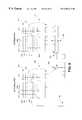
- FIG. 2is a block diagram of an embodiment of a signal detector in accordance with an embodiment of the subject invention.
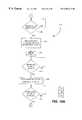
- FIG. 3is a flowchart illustrating an embodiment of a method of operation of the signal detector of FIG. 2 .
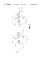
- FIG. 4illustrates an embodiment of a GPS receiver in accordance with the subject invention.
- FIG. 5illustrates the data structures output by one embodiment of a matched filter in accordance with the subject invention.
- FIG. 6illustrates data flows in one embodiment of a GPS receiver in accordance with the subject invention.
- FIG. 7is a timing diagram for combining multiple correlation arrays in accordance with one implementation of the subject invention.
- FIG. 8illustrates an embodiment of a matched filter in accordance with the subject invention.
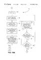
- FIG. 9illustrates an embodiment of a method of operation of a GPS receiver in accordance with the subject invention.
- FIGS. 10A-10Cillustrate an embodiment of a method of operation of a GPS receiver in accordance with the subject invention.
- FIGS. 11A-11Cillustrate an embodiment of a method of operation of a matched filter in accordance with the subject invention.
- FIG. 12illustrates an embodiment of a method of operation of a GPS receiver in accordance with the subject invention.
- FIGS. 13A-13Billustrate an embodiment of a method of operation of a GPS receiver in accordance with the subject invention.
- a signal detectorconfigured to combine the results of performing correlation analysis on segments of samples of the received signal that may have non-uniform lengths and that may have been obtained over different and non-overlapping periods of time.
- the segmentsare obtained during sampling windows of arbitrary length and at arbitrary times, and the results of processing the segments are successively combined until a threshold signal to noise ratio has been achieved.
- the signal detectoris part of a GPS receiver.
- the GPS receivercomprises a radio frequency (RF) receiver, sampling circuitry, timing circuitry, offset measurement circuitry, a PN code generator, a matched filter, and a GPS processor.
- the RF receiverdemodulates the received signal to obtain a baseband signal.
- the sampling circuitryprovides, responsive to timing signals produced by the timing circuitry, a segment of samples of the baseband signal taken over a defined sampling window.
- the matched filterprocesses the segment of samples in accordance with a plurality of PN code, Doppler shift, and code phase hypotheses.
- the matched filteroutputs correlation data derived by correlating various combinations of PN code, Doppler shift and code phase hypotheses with the segment of samples.
- the correlation datacan be grouped into groupings which correspond to various combinations of specific hypotheses and ranges of hypotheses.
- the correlation datacomprises a plurality of arrays, wherein each array corresponds to a PN code hypothesis, each row of an array corresponds to a Doppler shift hypothesis, each column of an array corresponds to a code phase hypothesis, and each entry in the array is a measure of the degree to which the combined PN code, Doppler shift, and code phase hypothesis corresponding to the entry correlates to the samples.
- the PN code generatorgenerates the PN code hypotheses which are provided as inputs to the matched filter.
- the Doppler shift hypothesesare generated internally within the matched filter.
- the GPS processorsends out data capture commands to the sampling circuitry and the matched filter directs the sampling circuitry to capture a segment of samples, and directs the matched filter to process the segment of samples.
- the GPS processoralso, responsive to timing signals generated locally by the GPS radio receiver, generates frame marks which are input to the offset measurement circuitry.
- the offset measurement circuitrydetermines the offset between the time that a data capture command is issued by the GPS processor and the timing of the next frame mark. This information is provided to the GPS processor for use in combining the results of processing different segments of samples.
- cumulative correlation datais maintained.
- the new correlation datais combined with the cumulative correlation data.
- the GPS processoraccumulates the correlation data for a particular satellite until a threshold signal to noise ratio is achieved.
- the data for a particular satelliteis maintained until the presence and range of the satellite can be determined.
- the correlation data for different segments of samplesare combined using an algorithm that allows for the differing code phases between the segments to be accounted for even through the actual code phases are unknown.
- the correlation data for a given segment of samplescomprises a plurality of arrays, wherein each array in the plurality corresponds to a particular PN code hypothesis, and each row of an array corresponds to a particular Doppler shift hypothesis, cumulative correlation arrays are initialized with the correlation arrays for the first segment. Then, the correlation arrays for the second segment are combined with the cumulative correlation arrays one array at a time, and within an array, one row at a time. The process continues indefinitely and ceases for a particular satellite (PN code) when the presence and range of the satellite is accurately detected.
- PN codesatellite
- the code phase difference corresponding to a rowis derived from the total time offset between the start of the first segment and the start of the second segment, and the Doppler shift hypothesis corresponding to the row.
- the code phase differenceis determined from the following equation:
- ⁇ CP[( F PN +D ) ⁇ T ] modulo 1 mS
- ⁇ CPis the code phase difference
- F PNis the nominal PN rate of 1.023 MHz
- Dis the Doppler shift hypothesis corresponding to the array
- ⁇ Tis the time offset between the beginning of the sampling period for the first segment, and that for the second segment.
- 1 mSis the period of the PN codes. Since the codes are periodic, the code phase difference of interest is the fractional part of the code period. This is reflected in the foregoing equation through the modulo 1 mS operation.
- the first and second segmentseach span at least a frame, and begin at a time which is offset from a frame mark.
- the offsets for the first and second segment, OS 1 and OS 2 , respectively,are each determined from the offset measurement circuitry. According to the implementation example, the offsets are used to determine ⁇ T in the foregoing equation as follows:
- T nis the timing of the frame mark which occurs at the beginning of the second segment, and from which OS 2 is defined.
- T 2is the timing of the frame mark which occurs at the beginning of the first segment, and from which OS 1 is defined.
- Sis the error in the local time base generated by a local crystal oscillator in the GPS receiver in relation to the time base defined at the GPS satellites. The GPS receiver determines this error and corrects for it in the foregoing equation.
- This code phase differenceis then used to combine the rows for the correlation arrays.
- the row of correlation data for the second segmentis circularly shifted by the code phase difference. Then, the shifted row is added to the corresponding row of cumulative correlation data, one data element at a time. This process is then repeated for each of the rows of each of the arrays for the second segment. The result is a plurality of cumulative correlation arrays which combine the results of the first and second segments.
- the correlation arrays for additional segmentsare combined with the cumulative correlation arrays in the foregoing manner. For a given satellite, the process of combining segments continues until the signal to noise ratio is sufficient to permit the presence and range of the satellite to be accurately determined.
- FIG. 2A block diagram of one embodiment of a signal detector in accordance with the subject invention is illustrated in FIG. 2 .
- the signal detectorcomprises a receiver 30 configured to receive segments of a signal.
- the segmentsmay be of nonuniform-length and may be disjoint and separated by arbitrary periods of time.
- the signalmay comprise a signal of interest perturbed by noise.
- the signalmay comprise the combination of multiple signals of interest each encoded using one of a plurality of pseudo-noise (PN) codes. In this case, other signals appear as noise to a particular signal of interest.
- PNpseudo-noise
- a hypothesis generator 32generates a plurality of hypotheses about the signal of interest.
- a correlator 34receives the plurality of hypotheses from hypothesis generator 32 , and the segment received by receiver 30 , and responsive thereto, generates correlation data representative of the correlation between the received segment and the plurality of generated hypotheses.
- the correlation datais provided to combiner 36 which combines the correlation data with cumulative correlation data accumulated for previous segments received by receiver 30 .
- the combiner 36first performs an adjustment on the correlation data so that it is combinable with the cumulative correlation data. Once the data has been combined, combiner 36 determines whether the cumulative correlation data is sufficient to permit a parameter of the signal of interest to be detected. If so, an output is provided on signal line 38 signaling detection of the parameter of the signal of interest. If not, a signal is provided to the receiver on signal line 40 indicating the need for additional segments.
- the foregoing processiterates until the parameter of the signal of interest is detected (or a time-out condition is detected).
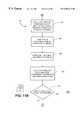
- FIG. 3A flowchart of one embodiment of a method of operation of a signal detector in accordance with the subject invention is illustrated in FIG. 3 .
- the processbegins at step 50 , in which a segment of the type described earlier is received. Then, in step 52 , a plurality of hypotheses are generated for testing. In step 54 , correlation data measuring the level of correlation between the received sample and the generated hypotheses is derived.
- step 56the correlation data from step 54 is combined with cumulative correlation data which may be present from correlation analysis performed on previous segments.
- the correlation data from step 54is first adjusted or altered so that it is combinable with the cumulative correlation data. If no such data is present, the cumulative correlation data is initialized with the correlation data derived in step 54 .
- step 58a determination is made whether the cumulative correlation data permits accurate and reliable detection of a desired parameter of the signal of interest. If so, the process ends. If not, a jump is made to step 50 and the process repeats itself from this point with a new segment. Optionally, the process iterates until the desired parameter of the signal of interest is detected (or a time-out condition occurs).
- the foregoing signal detectorcan be beneficially employed in a variety of applications, such as in a GPS receiver 70 .
- a GPS receiver 70in accordance with the subject invention is illustrated in FIG. 4 .
- the receiver 70comprises a radio frequency (RF) receiver 72 , sampling circuitry 74 , timing circuitry 76 , offset measurement circuitry 78 , a PN code generator 80 , a matched filter 82 , and a GPS processor 84 .
- the RF receiver section 72demodulates the received signal to obtain a baseband signal which is provided to the sampling circuitry 74 over signal line 86 .
- the sampling circuitry 74provides, responsive to timing signals produced by the timing circuitry 76 , a segment of samples of the baseband signal taken over a defined sampling window.
- the segment of samplesis provided to the matched filter 82 over signal line 88 .
- the matched filter 82processes the segment of samples in accordance with a plurality of PN code, Doppler shift, and code phase hypotheses.
- each array 110 , 112 , 114corresponds to a PN code hypothesis, PN 1 , PN 2 , . . . PNr, each row of an array 110 , 112 , 114 corresponds to a Doppler shift hypothesis, DS 1 , DS 2 , . . . DSm, each column of an array 110 , 112 , 114 corresponds to a code phase hypothesis, CP 1 , CP 2 , . . .
- correlation array 110corresponds to PN code hypothesis PN 1
- correlation array 112corresponds to PN code hypothesis PN 2
- correlation array 114corresponds to PN code hypothesis PNr.
- the PN code generator 80generates the PN code hypotheses which are provided as inputs to the matched filter 82 over signal line 90 .
- the Doppler shift hypothesesare generated internally within the matched filter.
- the GPS processor 84issues data capture commands on signal line 92 to the sampling circuitry 74 and the matched filter 82 directs the sampling circuitry 74 to capture a segment of samples, and directs the matched filter 82 to process the segment of samples.
- the GPS processor 84also, responsive to timing signals generated locally by the GPS radio receiver 72 and received over signal line 94 , generates frame marks which are input to the offset measurement circuitry 78 over signal line 96 .
- the timing signals generated by the GPS radio receiver 72are generated by a local oscillator within the RF receiver.
- the timing signalsdefine a local time base which is related to the time base maintained by the GPS satellites.
- the offset measurement circuitry 78determines the offset between the time that a data capture command is issued by the GPS processor and the time of the next frame mark. This information is provided to the GPS processor 84 for use in combining, in a manner to be described subsequently, the results of processing different segments of samples.
- the correlation arrays for a segmentare grouped by PN code hypothesis, and by Doppler shift hypothesis for a given PN code hypothesis. The result is that each grouping corresponds to a particular combination of PN code hypothesis and Doppler shift hypothesis.
- the correlation arraysare combined one grouping at a time.
- the GPS processor 84receives these groupings over signal line 98 , and cumulatively combines these correlation arrays as additional segments are captured. For a particular satellite, the combination process continues until a threshold signal to noise ratio is obtained for the satellite.
- the correlation arrays corresponding to a satelliteare combined until the presence and range of the satellite can be accurately determined. Typically, this occurs when the correlation data for a particular set of hypotheses is significantly greater than the correlation data for alternative hypotheses.
- the correlation arrays derived from different segments of samplesare combined using an algorithm that accounts for the differing code phases between the segments even though the actual code phases are unknown.
- a plurality of cumulative correlation arraysare maintained, which are initially set equal to the correlation arrays derived from a first segment of samples.
- the correlation arrays for a second segment of samplesare then combined with the cumulative correlation arrays one row at a time.
- the code phase difference corresponding to a rowis derived from the total time offset between the start of the first segment and the start of the second segment, and the Doppler shift hypothesis corresponding to the row.
- a circular shift of the row for the second segmentis then performed, with the amount of the shift being derived from the code phase difference which has been determined.
- the entries in the shifted roware then added to the corresponding entries of the corresponding row in the cumulative arrays.
- the foregoing combining processis then repeated for additional data in the correlation arrays for the second segment.
- the processis repeated for each of the rows in each of the arrays remaining in the correlation data for the second segment.
- the data for additional segmentsis combined with the cumulative arrays in the foregoing manner until, for a given satellite, the signal to noise ratio is sufficient to permit the presence and range of the satellite to be accurately determined.
- Numeral 120identifies one of the arrays in the plurality of cumulative correlation arrays which are maintained. The particular array which is identified is the one corresponding to PN code hypothesis PNi. These arrays are assumed to have been initially set equal to the correlation arrays derived from a first segment of samples.
- Numeral 122identifies the corresponding one of the arrays in the plurality of correlation arrays which are derived from a second set of samples. Again, this array corresponds to the PN code hypothesis PNi.
- the first segment of samplesis obtained during a first time period
- the second set of samplesis obtained during a subsequent non-consecutive time period.
- Row 124 from array 122is combined with the row 126 from array 120 in the manner shown. Both rows are assumed to correspond to the same Doppler shift hypothesis, DPi. Row 126 is obtained as indicated by identifying numeral 128 . In addition, row 124 is obtained as indicated by identifying numeral 130 . As indicated by identifying numeral 132 , the code phase difference, ⁇ CP, defining the code phase difference between the start of the first and second segments is determined. The row 124 obtained from array 122 is then circularly shifted by an amount derived from ⁇ CP. Such is indicated by identifying numeral 134 . The entries in the shifted row are then added to corresponding entries in row 126 . Such is indicated by identifying numeral 136 . The result is then stored in array 120 in lieu of row 126 . Such is indicated by identifying numeral 138 .
- the code phase differenceis determined from the following equation:
- ⁇ CP[( F PN +D ) ⁇ ⁇ T ] modulo 1 mS (1)
- ⁇ CPis the code phase difference
- F PNis the nominal PN rate of 1.023 MHz
- Dis the Doppler shift hypothesis corresponding to the row
- ⁇ Tis the time offset between the beginning of the sampling period for the first segment, and that for the second segment.
- 1 mSis the period of the PN codes. Since the codes are periodic, the code phase difference of interest is the fractional part of the code period. This is reflected in the foregoing equation through the modulo 1 mS operation.
- the first and second segmentseach span at least a frame, and begin at a time which is offset from a frame mark.
- the offsets for the first and second segments, OS 1 and OS 2 , respectively,are each determined from the offset measurement circuitry 78 (FIG. 4 ). According to the implementation example, the offsets are used to determine ⁇ T in the foregoing equation as follows:
- T nis the timing of the frame mark which occurs at the beginning of the second segment, and from which OS 2 is defined.
- T 2is the timing of the frame mark which occurs at the beginning of the first segment, and from which OS 1 is defined.
- Sis the error in the local time base generated by a local crystal oscillator in the GPS radio receiver 72 in relation to the time base defined at the GPS satellites. The GPS receiver determines this error and corrects for it in the foregoing equation.
- Local time base 150is divided into frames by frame marks T 1 , T 2 , . . . T n .
- the duration of a frameis 20 mS.
- GPS processor 84(FIG. 4) issues a command, identified with numeral 154 , to capture a first segment of samples.
- the capture of the first segment of samplesbegins at time 156 , and the segment itself is identified in the figure with numeral 158 .
- the first set of samplesis assumed to span at least one frame.
- the offset measurement circuitry 78(FIG.
- the segment of samples 158is typically representative of the combination of transmissions from multiple ones of GPS satellites, each of which has a different code phase as measured at the receiver. In relation to a particular satellite of interest, the segment 158 will have a specific code phase, CP 1 , which is identified in the figure with numeral 162 .
- the GPS processor 84(FIG. 4) issues another command to capture a segment of samples.
- This second commandis identified in FIG. 7 with numeral 164 , and is assumed to occur after the GPS processor 84 has detected the occurrence of frame mark T n ⁇ 1 .
- the capture of the second segmentwhich is identified with numeral 166 , begins at time 168 . Again, the second segment is assumed to span at least one frame.
- the next frame mark, T noccurs at time 170 .
- the offset measurement circuitry 78measures the offset, OS 2 , between the beginning 168 of the second segment, and the occurrence 170 of the next frame mark T n .
- This second frameis assumed to have a particular code phase, CP 2 , which is defined in relation to a particular satellite.
- the time ⁇ T in the foregoing equationsis the difference in time between the beginning 168 of the second segment, and the beginning 156 of the first segment, and the value ⁇ CP in the foregoing equations is the difference in code phase between the code phase for the first segment, CP 1 , and that for the second segment, CP 2 .
- this valueis determined from the foregoing equations even though the underlying code phases CP 1 and CP 2 are unknown.
- FIG. 8illustrates one embodiment of matched filter 82 in FIG. 4 .
- this embodiment of the matched filtercomprises random access memory (RAM) 180 which is configured to receive samples from sampling circuitry 74 (FIG. 4) over signal line 88 .
- RAMrandom access memory
- a frameis 20 mS in duration
- the RAM 180is configured to receive one 20 mS frame of samples at a time.
- each 20 mS frame of samplescomprises 40920 samples, obtained by sampling the baseband signal at a nominal sampling rate of 20.46 MHz, and then performing decimation filtering.
- Doppler shift correction circuitry 182is also provided.
- the RAM 180is configured to provide to Doppler shift correction circuitry 182 over signal line 186 at least a portion of a frame of samples stored therein at a time.
- the frame of samples stored in RAM 180is divided into subframes, and is provided to Doppler shift correction circuitry 182 one subframe at a time.
- the duration of a subframeis equal to the period of the PN codes, which is currently set to 1 mS.
- each subframe of samplescomprises 2046 samples, with each sample represented as a complex number having an in-phase (I) and a quadrature (Q) component which are typically expressed in combination as I+jQ.
- each component, whether I or Qis represented by 2 bits, and can take on any one of the discrete values ⁇ 1, 0, or +1.
- Doppler shift generator 184generates a plurality of Doppler shift hypotheses which are provided to Doppler shift correction circuitry 182 over signal line 188 one hypothesis at a time.
- the Doppler shift generator 184generates Doppler shift hypotheses in the range of ⁇ 62,000 Hz, to allow for additional inaccuracy in the local time base that is not corrected by the input sampling process.
- Sample register 190is also provided.
- Doppler shift correction circuitry 182receives a subframe of samples from RAM 180 over signal line, and a Doppler shift hypothesis from Doppler shift generator 184 , and, responsive thereto, generates a corrected subframe of samples which are stored in sample register 190 . Additional detail about this procedure is available in U.S. patent application Ser. No. 09/145,055, filed Sep. 1, 1998, entitled “DOPPLER CORRECTED SPREAD SPECTRUM MATCHED FILTER,” now U.S. Pat. No. 6,044,105, previously incorporated by reference herein as though set forth in full.
- each corrected subframe of samplescontinues to comprise 2046 complex samples, each having I and Q components.
- Each of the samples in this implementation examplecan take on any one of the discrete values ⁇ 2, ⁇ 1, 0, +1, and +2, which are represented by 3 bits for each of I and Q.
- PN code register 192is provided to store the current PN code hypothesis provided by PN code generator 80 (FIG. 4) over signal line 90 .
- each PN code hypothesisrepresents one period of a PN code.
- the PN code periodis 1 mS
- each PN code hypothesisrepresents 1023 chips which repeats every 1 mS, representing a chip rate of 1.023 MHz.
- the PN code registeris configured to store 1023 chips at a time.
- the PN code registeris capable of being circularly shifted by an amount which corresponds to a code phase delay hypothesis.
- the value of the code phase delaycan range from 0 to 2045 half chip increments.
- the PN code registeris configured in this implementation example to be circularly shifted by any number or fraction of chips which correspond to a code phase delay hypothesis under consideration.
- Sum of products circuitry 194is also provided. This circuitry is configured to form the integration of the product between the subframe of corrected samples stored in sample register 190 and the PN code hypothesis stored in the PN code register 192 .
- the subframe of samples stored in sample register 190comprises 2046 samples, each having I and Q components, and the PN code hypothesis stored in PN code register 192 comprises 1023 chips
- a correspondenceis present between two of the samples in the sample register 190 , and one of the chips in PN code register 192 .
- the I and the Q components of each of the two samplesis multiplied by the corresponding PN chip.
- the sum of the I component productsis determined, and the sum of the Q component products is separately determined.
- the sum of the I component productsis output on signal line 195
- the sum of the Q component productsis output on signal line 196 .
- I i 1is the I component of the first of the two samples corresponding to CHIP i
- I i 2is the I component of the second of the two samples corresponding to CHIP i
- Q i 1is the Q component of the first of the two samples corresponding to CHIP i
- Q i 2is the Q component of the second of the two samples corresponding to CHIP 1 .
- Sqrt. of sum of squares circuitry 198 , adder 202 , and RAM 200are also provided.
- the sqrt. of sum of squares circuit 198is configured to receive the sum of the I component products (SI) and the sum of the Q component products (SQ) on signal lines 195 and 196 respectively, and to determine the square root of the sum of the squares of these two values.
- the circuitcomputes the value:
- the foregoing valueis stored in an array entry in RAM 200 corresponding to the combination of the PN code, Doppler shift, and code phase hypotheses under consideration.
- the arraysare of the same format as those depicted in FIG. 5 and will eventually become the correlation arrays for the current PN hypothesis.
- the subframe under consideration and stored in sample register 190is not the first subframe analyzed for the frame of interest, there may already be a value derived from a previous subframe stored in RAM 200 in the entry corresponding to the combination of the PN code, Doppler shift, and code phase hypotheses under consideration.
- the SS value determined aboveis added by adder 202 with the previously stored value which is provided to the adder 202 over signal line 204 .
- the resultis then stored in lieu of the previously stored value in the array entry corresponding to the combined PN code, Doppler shift, and code phase hypotheses.
- next code phase hypothesisis then selected, and the PN code register 192 circularly shifted in accordance with the selected code phase hypothesis.
- the foregoing processis then repeated. This process continues for each of the code phase hypotheses which are desired to be tested.
- 2046 code phasesare tested for each 1 mS subframe, corresponding to the repetition period of the PN codes.
- the code phase hypotheses which are testedrange from 0 to 2045 half-chip increments, and the next code phase hypothesis is selected simply by circularly shifting the PN code register 192 by one-half chip.
- the matched filter of FIG. 8is configured to perform the foregoing tasks for each of the subframes of the frame stored in the RAM 180 .
- correlation arrays of the form shown in FIG. 5are present in RAM 200 . These correlation arrays are provided to the GPS processor 84 (FIG. 4) over signal line 98 . GPS processor 84 combines these correlation arrays with correlation arrays derived from a previous segment in the manner described previously.
- FIG. 9A first embodiment of an overall method of operation of the subject invention is illustrated in FIG. 9 .
- the process 220is iterative, and each cycle of the process 220 begins at step 222 .
- a segment of samplesis received.
- the segment sizeis variable from cycle to cycle.
- the segment sizeis fixed.
- the segment sizeis 20 mS.
- the PN code, Doppler shift, and code phase hypotheses to be testedare determined. In one embodiment, these hypotheses are variable from cycle to cycle. In another embodiment, these hypotheses are fixed. In one implementation, the PN code hypotheses to be tested are determined responsive to the satellites which have already been successfully detected. If a satellite has previously been successfully detected, then its PN code is removed from the set of PN code hypotheses to be tested. Similarly, the set of Doppler shift hypotheses to be tested may be reduced based on the Doppler shift values at which previous satellites have been detected.
- step 226correlation analyses are performed on the segment of samples in accordance with the set of hypotheses to be tested as determined in step 224 .
- the resultis correlation data which measures the level of correlation between various combinations of the tested hypotheses and the segment of samples.
- the correlation datais computed using equations (3), (4), and (5) above.
- this datais selectively combined with correlation data which has been accumulated from previous segments.
- this stepinvolves adjusting for the code phase difference between the current segment and the previous segments.
- this stepinvolves combining correlation arrays row by row after shifting at least one of the rows by the code phase difference which has been determined.
- the code phase differencesare computed in accordance with equations (1) and (2) above.
- step 230a determination is made whether the data which has been accumulated permits detection of the presence and range of a satellite. If so, then step 232 , in which the range of the satellite is determined, is performed. In one implementation, this step involves determining the range from the code phase hypothesis which has the highest correlation with the samples which have been accumulated. If not, a jump is made back to step 222 , whereupon the process 220 repeats itself with a new segment of samples.
- FIGS. 10A-10CA second embodiment of an overall method of operation of the subject invention is illustrated in FIGS. 10A-10C. Again, the process 220 ′ is iterative, and each cycle of the process begins with step 240 . According to this process, it is assumed that a time base exists which is divided up into successive periods known as epochs.
- an epochis a frame period. In one implementation example, an epoch is a 20 mS frame period. In the implementation which is the subject of the timing diagram of FIG. 7, epochs are the time periods marked by T 0 , T 1 , T 2 , . . . , T n , T n+1 , etc. In the scenario depicted in FIG. 7, numeral 152 identifies the beginning of a new epoch which is represented by T 1 .
- step 242is performed.
- the storage of receiver samplesis initiated before the commencement of the next epoch.
- the initiation of the new epoch at T 1generates an interrupt which causes the GPS processor 84 (FIG. 4) to issue a command to begin data capture.
- Such a commandis identified in FIG. 7 with numeral 154 .
- the commandis such that data capture begins before the beginning of the next epoch.
- the next epochis identified with numeral 160 , and is represented by T 2 .
- the capture of data samples from the receiveris commenced at the time identified with numeral 156 , which is before the commencement of the next epoch.
- a counterbegins counting. This is represented in FIG. 10A by step 244 which is performed after step 242 .
- the counteris part of the offset measurement circuitry 78 in FIG. 4 .
- Step 246is then performed.
- the systemloops until the next epoch is detected.
- the next epochisT 2 , and is identified with numeral 160 .
- step 248is performed.
- step 248the counter is stopped, and the contents of the counter used to derive the time offset OS I between the initiation of data capture and the beginning of the next epoch.
- this valueis represented as CP 1 , and is the time offset between the initiation of the capture of data segment 158 at the time identified with numeral 156 , and the time identified with numeral 160 (FIG. 7 ), which is the beginning of epoch T 2 .
- Step 250is then performed.
- the systemloops until data capture has been completed.
- the completion of data captureis detected by GPS processor 84 (FIG. 4) either by an interrupt which is generated or through a polling method.
- the completion of the capture of data samples 158 (FIG. 7)is identified with numeral 172 (FIG. 7 ).
- step 252(FIG. 10B) is performed.
- the contents of the counterwhich defines OS I , is saved and associated with the captured data samples.
- the GPS processor 84(FIG. 4) reads the contents of the counter maintained in the offset measurement circuitry 78 , and defines this value as CP 1 . The GPS processor 84 then saves this value and associates it with the data samples 158 (FIG. 7 ).
- the systemthen generates correlation data which describes the degree of correlation between the PN code, Doppler shift, and code phase hypotheses which are desired to be tested.
- the PN code hypothesis to be testedis selected, and in step 256 , the Doppler shift hypothesis to be tested is selected.
- the selected PN code hypothesisis generated by PN code generator 80 (FIG. 4 ), and then stored in PN code register 192 (FIG. 8 ).
- the Doppler shift hypothesisis generated by Doppler shift generator 184 (FIG. 8 ).
- Step 258is then performed.
- the receiver samples which have been capturedare corrected for the selected Doppler shift hypothesis.
- the receiver samplesare stored in RAM 180 (FIG. 8 ), and Doppler shift correction circuitry 182 corrects these samples for the selected Doppler shift hypothesis one subframe at a time. Additional detail regarding this implementation is available in U.S. Ser. No. 09/145,055, previously incorporated herein by reference.
- Step 260is then performed.
- step 260a cross-correlation analysis is then performed between the adjusted data from step 258 , and the PN code hypothesis which has been selected.
- the integral of the cross-product between the adjusted receiver samples and the PN code, shifted in accordance with a selected code phase hypothesis,is determined for each of a plurality of code phase hypotheses.
- 2046 code phase hypothesesare tested. These code phase hypotheses are generated by circularly shifting the selected PN hypothesis by a shift value ranging from 0 to 2045 half-chip increments. In one implementation example, this step is performed one subframe at a time.
- this stepis performed by the matched filter 82 (FIG. 4 and FIG. 8 ). In one implementation example, this step is performed in accordance with equations (3), (4), and (5) above.
- step 262is performed.
- the correlation data obtained in step 260is combined with any previous correlation data for the same PN code/Doppler shift hypotheses in a manner to be described subsequently.
- thisis the first set of correlation data obtained for the given PN code/Doppler shift hypotheses, these values are simply stored.
- the completion of the cross-correlation analysis of step 260is detected by GPS processor 84 (FIG. 4) through either an interrupt or a polling method.
- the correlation data for a segmentis combined with any previous correlation data using equations (1) and (2) above.
- step 264a determination is made whether there are any more Doppler shift hypotheses to be tested. If so, a jump is made back to step 256 , and the process is repeated beginning at this point. If not, step 266 is performed.
- step 266a determination is made whether there are any more PN code hypotheses to be tested. If so, a jump is made back to step 254 , and the process is repeated beginning at this point. If not, step 268 (FIG. 10C) is performed.
- step 268a determination is made whether there are any more data segments to be captured for combination with the results which have been accumulated. If so, a jump is made back to step 240 (FIG. 10 A), and the process is repeated beginning at this point. If not, the process terminates.
- the parameters which are collected for each set of data sampleschange.
- the first passis associated with the parameters OS 1 , T 2 , and CP 1 .
- the second passis associated with the parameters T n , OS 2 , and CP 2 .
- the data capture processis not limited to a fixed 20 mS epoch or segment length. In general, it can be adjusted on each pass to a variable length. In one implementation example, it can be adjusted on each pass to a variable length of from 1 to 20 mS, in 1 mS increments. In other implementation examples, longer periods are possible simply by increasing the amount of RAM 400 .
- the GPS processor 84(FIG. 4) has stored within its memory a plurality of correlation arrays, with each array corresponding to a particular PN code hypothesis, and with each row of an array corresponding to a particular Doppler shift hypothesis. Each array represents the combined results derived from multiple sets of samples.
- FIGS. 11A-11CA method 300 of operation of a matched filter in accordance with the subject invention is illustrated in FIGS. 11A-11C.
- step 302a frame of samples is stored.
- the frame of samplesis stored in RAM 180 .
- a PN code hypothesisis selected for testing and stored in a circular shift register.
- the PN code hypothesisis stored in PN code register 192 .
- step 306a subframe of the frame of samples stored in step 302 is selected.
- a Doppler shift hypothesisis selected for testing.
- this stepis implicitly performed by Doppler shift generator 184 which successively generates Doppler shift hypothesis responsive to constraints or bounds imposed by a user.
- the Doppler shift hypothesesrange from ⁇ 62,000 Hz.
- step 310the subframe selected in step 306 is corrected for the Doppler shift hypothesis selected in step 308 .
- this stepis performed by Doppler shift correction circuitry 182 .
- this stepis performed as described in U.S. Ser. No. 09/145,055, filed Sep. 1, 1998, previously incorporated herein by reference, now U.S. Pat. No. 6,044,105.
- step 312the corrected data from step 310 is stored, In the matched filter of FIG. 8, the corrected data is stored in sample register 190 .
- step 314a code phase hypothesis is selected for testing.
- this stepis implicit in the operation of PN code register 192 which successively and circularly shifts through each of the possible code phase hypotheses in a PN code repetition period, which, in one implementation, comprises 2046 half-chip increments.
- step 318the PN code hypothesis selected and stored in step 304 is circularly shifted by an amount derived from the code phase hypothesis selected in step 314 .
- the selected code phase hypothesisranges from 0 to 2045 half-chip increments, and step 318 is implemented by circularly shifting the PN code hypothesis by the number of half-chip increments comprising the selected code phase hypothesis.
- step 320the product of the shifted PN code from step 318 , and the corrected subframe of samples from step 310 is obtained.
- this stepcomprises forming the I and Q component sum of products, SI and SQ.
- SI and SQare derived in accordance with equations (3) and (4), presented earlier. In the matched filter of FIG. 8, this step is performed by sum of products circuitry 194 .
- step 322the square root of the sum of the squares of SI and SQ from step 320 is determined in accordance with equation (5), presented earlier. In the matched filter of FIG. 8, this step is performed by sqrt. of sum of products circuitry 198 .
- step 324the value determined in step 322 is added to any similar values derived from the same hypotheses for previous subframes of the frame which is the subject of step 302 , and the combined result is then stored.
- this stepis performed by the adder 202 in combination with RAM 200 , with the combined values being maintained in RAM 200 .
- step 326a determination is made whether there are any further code phase hypotheses which are to be tested for the selected PN code and Doppler shift hypotheses. If so, a jump is made to step 314 and the process beginning at this point repeated for the new code phase hypothesis. If not, step 328 (FIG. 11C) is performed. In the matched filter of FIG. 8, this step is implicit in the operation of PN code register 192 , which successively shifts through the 2046 code phase hypotheses to be tested for a given PN code and Doppler shift hypothesis.
- step 328(FIG. 11 C), a determination is made whether there are any further Doppler shift hypotheses which are to be tested for the selected PN code hypothesis. If so, a jump is made to step 308 , and the process beginning at this point repeated for the new Doppler shift hypothesis. If not, step 330 is performed. In the matched filter of FIG. 8, this step is implicit in the operation of Doppler shift generator 184 , which cycles through a plurality of Doppler shift hypotheses for a given PN code hypothesis. In one implementation example, the Doppler shift hypotheses tested for a given PN code hypothesis range from ⁇ 62,000 Hz.
- step 330a determination is made whether there are any further subframes to be analyzed of the frame which is the subject of step 302 . If so, a jump is made to step 306 and the process beginning at this point repeats itself using the new subframe. If not, the process terminates.
- the method illustrated in FIGS. 11A-11Cis then repeated for each PN code hypothesis which is to be tested. In one implementation example, the coordination of this task is performed by GPS processor 84 (FIG. 4 ).
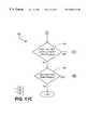
- step 350An embodiment of method of updating the cumulative correlation data with the correlation data derived from a new segment in accordance with the subject invention is illustrated in FIG. 12 .
- step 350a portion of the cumulative correlation data which is to be updated is obtained.
- this portionis the cumulative correlation data which corresponds to a particular combination of PN code and Doppler shift hypotheses.
- step 352the corresponding portion of the incremental correlation data, that is, the correlation data derived from a new segment, is obtained.
- this portionis the incremental correlation data which corresponds to a particular combination of PN code and Doppler shift hypotheses.
- step 354the code phase difference, ACP, between the two portions is determined.
- this valueis derived from the Doppler shift hypothesis corresponding to the two portions, and the time difference between the start of a first segment of samples and a second segment of samples.
- ACPis determined in accordance with equations (1) and (2) above.
- step 356the portion of the incremental correlation data obtained in step 352 is adjusted responsive to the code phase difference between the two portions determined in step 354 .
- this stepcomprises circularly shifting a row of the incremental data by a value derived from the code phase difference determined in step 354 .
- the value ACPis computed using equations (1) and (2) above, and the shift value, SHIFT, is determined from the following equation:
- step 358the portion of the cumulative correlation data obtained in step 350 is updated with the adjusted data determined in step 358 .
- this stepcomprises adding a row of circularly shifted incremental data element by element to a corresponding row of cumulative data.
- step 360a determination is made whether there are any additional portions of cumulative data to update. If so, the process repeats beginning with step 350 for another portion of the cumulative data which is to be updated. If not, the process ends as indicated by identifying numeral 362 .
- FIGS. 13A and 13BA second embodiment of a method of updating cumulative correlation data with incremental correlation data is illustrated in FIGS. 13A and 13B. In this embodiment, it is assumed that each of the cumulative data and the incremental data are of the form shown in FIG. 5 .
- step 370in which a PN code hypothesis is selected. Then, in step 372 , the cumulative correlation array for the selected PN code hypothesis is obtained, and in step 374 , the incremental correlation array for the selected PN code hypothesis is obtained.
- step 376a Doppler shift hypothesis is selected, and in step 378 (FIG. 13 A), the code phase difference, ACP, for the selected Doppler shift hypothesis is determined.
- this valueis determined in accordance with equations (1) and (2) above.
- step 380the corresponding row of the incremental array obtained in step 374 is circularly shifted by an amount derived from the code phase difference determined in step 378 .
- this valueis determined in accordance with equation (6) above.
- step 382the shifted row from step 380 is added element by element to the corresponding row in the cumulative array.
- step 384(FIG. 13 B) a determination is made whether there are additional Doppler shift hypotheses to be updated. If so, a jump is made to step 376 (FIG. 13A) whereupon the process beginning at this step is repeated for one of the additional Doppler shift hypotheses to be updated. If not, step 386 is performed. In step 386 , a determination is made whether there are additional PN code hypotheses to be updated. If so, a jump is made to step 370 (FIG. 13A) whereupon the process beginning at this step is repeated for one of the additional PN code hypotheses to be updated, the process terminates, as indicated by identifying numeral 388 .
- a matched filter chip code-named “Magna”which combines the functionality of the sampling circuitry 74 , the timing circuitry 76 , offset measurement circuit 78 , and the matched filter 82 of FIG. 4 has been developed by the assignee of the subject application (Conexant Systems, Inc. of Newport Beach, Calif.).
- a processor chipwhich embodies the functionality of the GPS processor 84 of FIG. 4 code-named “Scorpio”, Part No. 11577-11, is available from the assignee of the subject application.
- the processorhas additional GPS-specific circuits, such as tracking channels for continuously tracking a number of GPS satellite signals 20 (FIG. 1 ).
- the processorincludes at least an embedded microprocessor with an external bus.
- the processorviews the matched filter chip as a memory mapped peripheral. It issues commands to the matched filter chip, and retrieves results after it has completed processing for a given set of commands.
- An RF receiver chipwhich embodies the functionality of the GPS radio receiver 72 of FIG. 4 code-named “Gemini/Pices Monopack”, Part No. R6732-13, is available from the assignee of the subject application. Additional details regarding this implementation example are available in U.S. Ser. No. 09/145,055, filed Sep. 1, 1998 previously incorporated herein by reference, now U.S. Pat. No. 6,044,105.
- the embodiments, implementations, and examplesare adaptable to any time base. This means that they can be applied to GPS chip sets, cellular and PCS chip sets, and standard microprocessors.
- the embodiments, implementations, and implementation examplesallow for the combination of non-uniform receiver sample capture lengths. This is critical for integrated applications such as cellular and PCS, in which it is desirable to receive GPS when the phone is not transmitting. Since the available idle slots will have different durations in the various phone standards, adaptability of time intervals is important.
- the embodiments, implementations, and implementation examplesallow arbitrary offsets in the start of the data capture times. This again is most important for phone applications, but it is also important for the basic GPS application. In the GPS application, a flexible start time capability allows the same capture to be used with any satellite in the received samples, regardless of their relative code phases.
- Processor RAM and throughputis minimized. This is important for phone applications, in which the baseband device's digital signal processor (DSP) and protocol stack processors may be busy and RAM limited. For high SNR cases, the entire required RAM for a given PN code is located on or within the matched filter. When data combining is required to improve SNR, only those satellite that have not been detected need be processed. Further, it is often possible in phone systems to reduce the size of the array to less than 2046 elements per PN code and Doppler shift hypothesis, and to a few Doppler shift hypotheses, using information that is inherent in mobile phone network operation.
- a generic processoris defined to mean any device, including a computer, DSP, baseband processor, microprocessor, or microcomputer, which is capable of executing a discrete series of instructions stored in a memory accessible by the processor. It should also be understood that embodiments are possible in which analog circuitry is used to perform these functions.
Landscapes
- Engineering & Computer Science (AREA)
- Radar, Positioning & Navigation (AREA)
- Remote Sensing (AREA)
- Computer Networks & Wireless Communication (AREA)
- Physics & Mathematics (AREA)
- General Physics & Mathematics (AREA)
- Position Fixing By Use Of Radio Waves (AREA)
- Separation By Low-Temperature Treatments (AREA)
- Radio Relay Systems (AREA)
Abstract
Description


Claims (87)
Priority Applications (9)
| Application Number | Priority Date | Filing Date | Title |
|---|---|---|---|
| US09/281,741US6304216B1 (en) | 1999-03-30 | 1999-03-30 | Signal detector employing correlation analysis of non-uniform and disjoint sample segments |
| AT00919870TATE418079T1 (en) | 1999-03-30 | 2000-03-29 | SIGNAL DETECTOR WITH CORRELATION ANALYSIS OF NON-UNITY AND SEPARATE SAMPLING SEGMENTS |
| JP2000608193AJP3964621B2 (en) | 1999-03-30 | 2000-03-29 | Signal detector using correlation analysis of multiple sample segments that are non-uniform and unconnected |
| DE60041128TDE60041128D1 (en) | 1999-03-30 | 2000-03-29 | NATURAL AND SEPARATED DESERT SEGMENTS |
| PCT/US2000/008422WO2000058746A1 (en) | 1999-03-30 | 2000-03-29 | Signal detector employing correlation analysis of non-uniform and disjoint sample segments |
| EP00919870AEP1173778B1 (en) | 1999-03-30 | 2000-03-29 | Signal detector employing correlation analysis of non-uniform and disjoint sample segments |
| TW089105655ATW500927B (en) | 1999-03-30 | 2000-04-06 | Signal detector employing correlation analysis of non-uniform and disjoint sample segments |
| US09/971,293US6636178B2 (en) | 1999-03-30 | 2001-10-04 | Signal detector employing correlation analysis of non-uniform and disjoint sample segments |
| US10/644,311US7002516B2 (en) | 1999-03-30 | 2003-08-19 | Signal detector employing correlation analysis of non-uniform and disjoint sample segments |
Applications Claiming Priority (1)
| Application Number | Priority Date | Filing Date | Title |
|---|---|---|---|
| US09/281,741US6304216B1 (en) | 1999-03-30 | 1999-03-30 | Signal detector employing correlation analysis of non-uniform and disjoint sample segments |
Related Child Applications (2)
| Application Number | Title | Priority Date | Filing Date |
|---|---|---|---|
| US09/971,293ContinuationUS6636178B2 (en) | 1999-03-30 | 2001-10-04 | Signal detector employing correlation analysis of non-uniform and disjoint sample segments |
| US09/971,239ContinuationUS6946148B2 (en) | 1999-03-30 | 2001-10-04 | Method for absorbing fluid |
Publications (1)
| Publication Number | Publication Date |
|---|---|
| US6304216B1true US6304216B1 (en) | 2001-10-16 |
Family
ID=23078602
Family Applications (3)
| Application Number | Title | Priority Date | Filing Date |
|---|---|---|---|
| US09/281,741Expired - LifetimeUS6304216B1 (en) | 1999-03-30 | 1999-03-30 | Signal detector employing correlation analysis of non-uniform and disjoint sample segments |
| US09/971,293Expired - LifetimeUS6636178B2 (en) | 1999-03-30 | 2001-10-04 | Signal detector employing correlation analysis of non-uniform and disjoint sample segments |
| US10/644,311Expired - LifetimeUS7002516B2 (en) | 1999-03-30 | 2003-08-19 | Signal detector employing correlation analysis of non-uniform and disjoint sample segments |
Family Applications After (2)
| Application Number | Title | Priority Date | Filing Date |
|---|---|---|---|
| US09/971,293Expired - LifetimeUS6636178B2 (en) | 1999-03-30 | 2001-10-04 | Signal detector employing correlation analysis of non-uniform and disjoint sample segments |
| US10/644,311Expired - LifetimeUS7002516B2 (en) | 1999-03-30 | 2003-08-19 | Signal detector employing correlation analysis of non-uniform and disjoint sample segments |
Country Status (7)
| Country | Link |
|---|---|
| US (3) | US6304216B1 (en) |
| EP (1) | EP1173778B1 (en) |
| JP (1) | JP3964621B2 (en) |
| AT (1) | ATE418079T1 (en) |
| DE (1) | DE60041128D1 (en) |
| TW (1) | TW500927B (en) |
| WO (1) | WO2000058746A1 (en) |
Cited By (57)
| Publication number | Priority date | Publication date | Assignee | Title |
|---|---|---|---|---|
| US20020012387A1 (en)* | 2000-03-13 | 2002-01-31 | Kaveh Shakeri | Low power passive correlators for multichannel global positioning system signal receiver |
| US20020075942A1 (en)* | 2000-12-18 | 2002-06-20 | Christopher Patrick | Method and apparatus for reducing code phase search space |
| US20020161522A1 (en)* | 2001-02-05 | 2002-10-31 | Clark Cohen | Low cost system and method for making dual band GPS measurements |
| US6542538B2 (en)* | 2000-01-10 | 2003-04-01 | Qualcomm Incorporated | Method and apparatus for testing wireless communication channels |
| US6611757B2 (en)* | 1999-04-30 | 2003-08-26 | Sirf Technology, Inc. | Global positioning system tag system |
| US6636178B2 (en)* | 1999-03-30 | 2003-10-21 | Sirf Technology, Inc. | Signal detector employing correlation analysis of non-uniform and disjoint sample segments |
| US6646596B2 (en)* | 2001-11-13 | 2003-11-11 | Nokia Corporation | Method, system and devices for positioning a receiver |
| US20040062297A1 (en)* | 2002-10-01 | 2004-04-01 | Mcdonough John G. | System and method for performing symbol boundary-aligned search of direct sequence spread spectrum signals |
| US6731672B1 (en)* | 1999-04-21 | 2004-05-04 | Trimble Navigation Limited | GPS receiver having improved signal acquisition at a low signal to noise ratio |
| US20060114984A1 (en)* | 2004-11-17 | 2006-06-01 | Peter Gaal | Method and apparatus for increasing coherent integration length while receiving a positioning signal |
| US20060121915A1 (en)* | 2002-04-01 | 2006-06-08 | Christopher Patrick | System, method, and apparatus for correction of code doppler shift |
| US20070160121A1 (en)* | 2001-05-18 | 2007-07-12 | Global Locate, Inc. | Method and apparatus for performing signal correlation |
| US20070183487A1 (en)* | 2005-12-21 | 2007-08-09 | Nemerix Sa | Optimal use of resources for signal processors |
| US7453961B1 (en) | 2005-01-11 | 2008-11-18 | Itt Manufacturing Enterprises, Inc. | Methods and apparatus for detection of signal timing |
| US20080294710A1 (en)* | 2007-05-22 | 2008-11-27 | Harris Corporation | Extending a Repetition Period of a Random Sequence |
| US20080307024A1 (en)* | 2007-06-07 | 2008-12-11 | Harris Corporation | Mixed Radix Number Generator with Chosen Statistical Artifacts |
| US20080304666A1 (en)* | 2007-06-07 | 2008-12-11 | Harris Corporation | Spread Spectrum Communications System and Method Utilizing Chaotic Sequence |
| US20080307022A1 (en)* | 2007-06-07 | 2008-12-11 | Harris Corporation | Mixed Radix Conversion with a Priori Defined Statistical Artifacts |
| US20090034727A1 (en)* | 2007-08-01 | 2009-02-05 | Harris Corporation | Chaotic Spread Spectrum Communications System Receiver |
| US20090044080A1 (en)* | 2007-05-31 | 2009-02-12 | Harris Corporation | Closed Galois Field Combination |
| US20090110197A1 (en)* | 2007-10-30 | 2009-04-30 | Harris Corporation | Cryptographic system configured for extending a repetition period of a random sequence |
| US7567636B2 (en) | 2001-05-18 | 2009-07-28 | Global Locate, Inc. | Method and apparatus for performing signal correlation using historical correlation data |
| US20090196420A1 (en)* | 2008-02-05 | 2009-08-06 | Harris Corporation | Cryptographic system incorporating a digitally generated chaotic numerical sequence |
| US20090202067A1 (en)* | 2008-02-07 | 2009-08-13 | Harris Corporation | Cryptographic system configured to perform a mixed radix conversion with a priori defined statistical artifacts |
| US20090237302A1 (en)* | 2006-04-25 | 2009-09-24 | Eric Derbez | Autonomous orbit propagation system and method |
| US20090245327A1 (en)* | 2008-03-26 | 2009-10-01 | Harris Corporation | Selective noise cancellation of a spread spectrum signal |
| US20090269538A1 (en)* | 2007-01-10 | 2009-10-29 | Benecke-Kaliko Ag | Thermoplastic film |
| US20090279688A1 (en)* | 2008-05-06 | 2009-11-12 | Harris Corporation | Closed galois field cryptographic system |
| US20090279690A1 (en)* | 2008-05-08 | 2009-11-12 | Harris Corporation | Cryptographic system including a mixed radix number generator with chosen statistical artifacts |
| US20090296860A1 (en)* | 2008-06-02 | 2009-12-03 | Harris Corporation | Adaptive correlation |
| US20090310650A1 (en)* | 2008-06-12 | 2009-12-17 | Harris Corporation | Featureless coherent chaotic amplitude modulation |
| US20090327387A1 (en)* | 2008-05-29 | 2009-12-31 | Harris Corporation | Digital generation of an accelerated or decelerated chaotic numerical sequence |
| US20100090896A1 (en)* | 2006-04-25 | 2010-04-15 | Lamance James W | Distributed orbit modeling and propagation method for a predicted and real-time assisted gps system |
| US20100098136A1 (en)* | 2001-05-18 | 2010-04-22 | Charles Abraham | Method and apparatus for performing signal correlation at multiple resolutions to mitigate multipath interference |
| US20100165828A1 (en)* | 2008-12-29 | 2010-07-01 | Harris Corporation | Communications system employing chaotic spreading codes with static offsets |
| US20100166041A1 (en)* | 2008-12-29 | 2010-07-01 | Harris Corporation | Communications system employing orthogonal chaotic spreading codes |
| US20100226497A1 (en)* | 2009-03-03 | 2010-09-09 | Harris Corporation | Communications system employing orthogonal chaotic spreading codes |
| US20100316090A1 (en)* | 2009-06-10 | 2010-12-16 | Harris Corporation | Discrete time chaos dithering |
| US20110002362A1 (en)* | 2009-07-01 | 2011-01-06 | Harris Corporation | symbol estimation for chaotic spread spectrum signal |
| US20110004792A1 (en)* | 2009-07-01 | 2011-01-06 | Harris Corporation | Bit error rate reduction in chaotic communications |
| US20110002360A1 (en)* | 2009-07-01 | 2011-01-06 | Harris Corporation | Permission-based secure multiple access communication systems |
| US20110019719A1 (en)* | 2009-07-22 | 2011-01-27 | Harris Corporation | Adaptive link communications using adaptive chaotic spread waveform |
| US7995682B2 (en) | 2001-05-18 | 2011-08-09 | Broadcom Corporation | Method and apparatus for performing signal processing using historical correlation data |
| US8060109B2 (en) | 1997-08-04 | 2011-11-15 | Enovsys Llc | Authorized location reporting mobile communication system |
| US8165065B2 (en) | 2008-10-09 | 2012-04-24 | Harris Corporation | Ad-hoc network acquisition using chaotic sequence spread waveform |
| US8312551B2 (en) | 2007-02-15 | 2012-11-13 | Harris Corporation | Low level sequence as an anti-tamper Mechanism |
| US8325702B2 (en) | 2008-08-29 | 2012-12-04 | Harris Corporation | Multi-tier ad-hoc network in which at least two types of non-interfering waveforms are communicated during a timeslot |
| US8340295B2 (en) | 2009-07-01 | 2012-12-25 | Harris Corporation | High-speed cryptographic system using chaotic sequences |
| US8345725B2 (en) | 2010-03-11 | 2013-01-01 | Harris Corporation | Hidden Markov Model detection for spread spectrum waveforms |
| US8363700B2 (en) | 2009-07-01 | 2013-01-29 | Harris Corporation | Rake receiver for spread spectrum chaotic communications systems |
| US8379689B2 (en) | 2009-07-01 | 2013-02-19 | Harris Corporation | Anti-jam communications having selectively variable peak-to-average power ratio including a chaotic constant amplitude zero autocorrelation waveform |
| US8428104B2 (en) | 2009-07-01 | 2013-04-23 | Harris Corporation | Permission-based multiple access communications systems |
| US8428102B2 (en) | 2009-06-08 | 2013-04-23 | Harris Corporation | Continuous time chaos dithering |
| US8472503B2 (en) | 2003-10-22 | 2013-06-25 | Global Locate, Inc. | Method and apparatus for performing frequency synchronization |
| US8509284B2 (en) | 2009-06-08 | 2013-08-13 | Harris Corporation | Symbol duration dithering for secured chaotic communications |
| US8611530B2 (en) | 2007-05-22 | 2013-12-17 | Harris Corporation | Encryption via induced unweighted errors |
| US8848909B2 (en) | 2009-07-22 | 2014-09-30 | Harris Corporation | Permission-based TDMA chaotic communication systems |
Families Citing this family (16)
| Publication number | Priority date | Publication date | Assignee | Title |
|---|---|---|---|---|
| US6577271B1 (en)* | 1999-03-30 | 2003-06-10 | Sirf Technology, Inc | Signal detector employing coherent integration |
| US7069019B2 (en)* | 2001-09-08 | 2006-06-27 | Sirf Technology, Inc. | System and method to estimate the location of a receiver |
| GB2400282B8 (en)* | 2003-03-31 | 2014-08-27 | St Microelectronics Res & Dev | Integrated circuit for code acquisition |
| US7453956B2 (en)* | 2004-08-16 | 2008-11-18 | Sony Ericsson Mobile Communications Ab | Apparatus, methods and computer program products for signal acquisition using common demodulation templates |
| US7382310B1 (en)* | 2006-01-03 | 2008-06-03 | Gregory Hubert Piesinger | Method for independently setting range resolution, Doppler resolution, and processing gain of a pseudo-random coded radar system |
| CN101427152A (en)* | 2006-03-09 | 2009-05-06 | 联邦科学和工业研究组织 | A method and apparatus for tracking position |
| DE102006060002A1 (en)* | 2006-12-19 | 2008-06-26 | Siemens Programm- Und Systementwicklung Gmbh & Co. Kg | Method, system and device for data reduction in a mobile radio network |
| US20080151813A1 (en)* | 2006-12-22 | 2008-06-26 | Adaptix, Inc. | Method and apparatus for fast system initial acquisition in mobile WiMAX systems |
| US8238489B2 (en)* | 2008-02-19 | 2012-08-07 | Core Logic, Inc. | Apparatus and method for processing signal using single correlator |
| US8244183B2 (en)* | 2008-08-12 | 2012-08-14 | Qualcomm Incorporated | Concurrent sync channel searching |
| US8200446B2 (en) | 2008-12-12 | 2012-06-12 | Qualcomm Incorporated | Waveform correlation result processing methods and apparatuses |
| US8233516B2 (en)* | 2009-06-24 | 2012-07-31 | Qualcomm Incorporated | Wideband correlation mode switching methods and apparatuses |
| KR101709804B1 (en) | 2009-07-01 | 2017-02-23 | 로카타 코퍼레이션 피티와이 리미티드 | Method and apparatus for forming a beam |
| GB2487044A (en)* | 2010-12-24 | 2012-07-11 | Enmodus Ltd | Determining whether a signal is present by comparing phase measurements, and distinguishing between signals |
| CA2879155C (en) | 2012-07-20 | 2024-04-30 | Prevtec Microbia Inc. | Non-pathogenic f18 e. coli strain and use thereof |
| US11579311B2 (en)* | 2020-12-07 | 2023-02-14 | U-Blox Ag | Methods, devices, systems, media, and receivers for processing GNSS signals |
Citations (140)
| Publication number | Priority date | Publication date | Assignee | Title |
|---|---|---|---|---|
| US3604911A (en) | 1969-05-15 | 1971-09-14 | Sylvania Electric Prod | Serial-parallel digital correlator |
| US3975628A (en) | 1975-04-02 | 1976-08-17 | Hughes Aircraft Company | Optical heterodyne receiver with phase or frequency lock |
| US4426712A (en) | 1981-05-22 | 1984-01-17 | Massachusetts Institute Of Technology | Correlation system for global position receiver |
| US4445118A (en) | 1981-05-22 | 1984-04-24 | The United States Of America As Represented By The Administrator Of The National Aeronautics And Space Administration | Navigation system and method |
| US4463357A (en) | 1981-11-17 | 1984-07-31 | The United States Of America As Represented By The Administrator Of The National Aeronautics And Space Administration | Method and apparatus for calibrating the ionosphere and application to surveillance of geophysical events |
| US4578678A (en) | 1983-11-14 | 1986-03-25 | The United States Of America As Represented By The United States National Aeronautics And Space Administration | High dynamic global positioning system receiver |
| US4667203A (en) | 1982-03-01 | 1987-05-19 | Aero Service Div, Western Geophysical | Method and system for determining position using signals from satellites |
| US4701934A (en) | 1985-09-03 | 1987-10-20 | Motorola, Inc. | Method of doppler searching in a digital GPS receiver |
| US4754465A (en) | 1984-05-07 | 1988-06-28 | Trimble Navigation, Inc. | Global positioning system course acquisition code receiver |
| US4785463A (en) | 1985-09-03 | 1988-11-15 | Motorola, Inc. | Digital global positioning system receiver |
| US4809005A (en) | 1982-03-01 | 1989-02-28 | Western Atlas International, Inc. | Multi-antenna gas receiver for seismic survey vessels |
| US4821294A (en) | 1987-07-08 | 1989-04-11 | California Institute Of Technology | Digital signal processor and processing method for GPS receivers |
| US4890233A (en) | 1986-10-27 | 1989-12-26 | Pioneer Electronic Corporation | Vehicle bearing detection and data processing methods applicable to vehicle navigation system |
| US4894842A (en) | 1987-10-15 | 1990-01-16 | The Charles Stark Draper Laboratory, Inc. | Precorrelation digital spread spectrum receiver |
| US4894662A (en) | 1982-03-01 | 1990-01-16 | Western Atlas International, Inc. | Method and system for determining position on a moving platform, such as a ship, using signals from GPS satellites |
| US4992720A (en) | 1988-01-29 | 1991-02-12 | Nec Corporation | Charge control circuit for cordless telephone system |
| US4998111A (en) | 1989-11-27 | 1991-03-05 | Motorola, Inc. | CPS transform correlation receiver and method |
| US5014066A (en) | 1982-03-01 | 1991-05-07 | Western Atlas International, Inc. | System for simultaneously deriving position information from a plurality of satellite transmissions |
| US5018088A (en) | 1989-10-02 | 1991-05-21 | The Johns Hopkins University | Adaptive locally-optimum detection signal processor and processing methods |
| US5036329A (en) | 1989-11-22 | 1991-07-30 | Pioneer Electronic Corporation | GPS satellite signal tracking method for GPS receivers |
| US5043736A (en) | 1990-07-27 | 1991-08-27 | Cae-Link Corporation | Cellular position locating system |
| US5108334A (en) | 1989-06-01 | 1992-04-28 | Trimble Navigation, Ltd. | Dual down conversion GPS receiver with single local oscillator |
| US5148042A (en) | 1989-12-29 | 1992-09-15 | Kabushiki Kaisha Toshiba | Small electronic device capable of switching batteries by releasing a battery locking mechanism |
| US5153591A (en) | 1988-07-05 | 1992-10-06 | British Telecommunications Public Limited Company | Method and apparatus for encoding, decoding and transmitting data in compressed form |
| US5179724A (en) | 1991-01-15 | 1993-01-12 | Ericsson G.E. Mobile Communications Holding Inc. | Conserving power in hand held mobile telephones during a receiving mode of operation |
| US5202829A (en) | 1991-06-10 | 1993-04-13 | Trimble Navigation Limited | Exploration system and method for high-accuracy and high-confidence level relative position and velocity determinations |
| US5225842A (en) | 1991-05-09 | 1993-07-06 | Navsys Corporation | Vehicle tracking system employing global positioning system (gps) satellites |
| US5253268A (en) | 1990-05-24 | 1993-10-12 | Cylink Corporation | Method and apparatus for the correlation of sample bits of spread spectrum radio signals |
| US5276765A (en) | 1988-03-11 | 1994-01-04 | British Telecommunications Public Limited Company | Voice activity detection |
| US5293398A (en) | 1991-12-13 | 1994-03-08 | Clarion Co., Ltd. | Digital matched filter |
| US5293170A (en) | 1991-04-10 | 1994-03-08 | Ashtech Inc. | Global positioning system receiver digital processing technique |
| US5297097A (en) | 1988-06-17 | 1994-03-22 | Hitachi Ltd. | Large scale integrated circuit for low voltage operation |
| US5311195A (en) | 1991-08-30 | 1994-05-10 | Etak, Inc. | Combined relative and absolute positioning method and apparatus |
| US5323164A (en) | 1992-03-16 | 1994-06-21 | Pioneer Electronic Corporation | Satellite radio wave capturing method for a global positioning system (GPS) receiver |
| US5343209A (en) | 1992-05-07 | 1994-08-30 | Sennott James W | Navigation receiver with coupled signal-tracking channels |
| US5345244A (en) | 1993-01-12 | 1994-09-06 | Trimble Navigation Limited | Cordless SPS smart antenna device |
| US5347536A (en) | 1993-03-17 | 1994-09-13 | The United States Of America As Represented By The Administrator Of The National Aeronautics And Space Administration | Multipath noise reduction for spread spectrum signals |
| US5352970A (en) | 1992-11-25 | 1994-10-04 | Benchmarq Microelectronics, Inc. | Power resource management system |
| US5363030A (en) | 1991-09-16 | 1994-11-08 | Motorola, Inc. | Battery having a transistor switch for supplying energy |
| US5379224A (en) | 1991-11-29 | 1995-01-03 | Navsys Corporation | GPS tracking system |
| US5378155A (en) | 1992-07-21 | 1995-01-03 | Teledyne, Inc. | Combat training system and method including jamming |
| US5396515A (en) | 1989-08-07 | 1995-03-07 | Omnipoint Corporation | Asymmetric spread spectrum correlator |
| US5402346A (en) | 1992-09-15 | 1995-03-28 | Thomson Csf | System for the calculation of at least one vehicular traffic check parameter |
| US5402347A (en) | 1993-07-22 | 1995-03-28 | Trimble Navigation Limited | Satellite search methods for improving time to first fix in a GPS receiver |
| US5410747A (en) | 1990-07-31 | 1995-04-25 | Nec Corporation | Dual conversion transmitter |
| US5416712A (en) | 1993-05-28 | 1995-05-16 | Trimble Navigation Limited | Position and velocity estimation system for adaptive weighting of GPS and dead-reckoning information |
| US5418818A (en) | 1992-09-22 | 1995-05-23 | Glenayre Electronics, Inc. | Digital signal processor exciter |
| US5420593A (en) | 1993-04-09 | 1995-05-30 | Trimble Navigation Limited | Method and apparatus for accelerating code correlation searches in initial acquisition and doppler and code phase in re-acquisition of GPS satellite signals |
| US5440313A (en) | 1993-05-27 | 1995-08-08 | Stellar Gps Corporation | GPS synchronized frequency/time source |
| US5450344A (en) | 1994-04-22 | 1995-09-12 | Trimble Navigation Limited | GPS receivers with data ports for the uploading and downloading of absolute position information |
| US5498239A (en) | 1995-04-17 | 1996-03-12 | Guided Medical Systems, Inc. | Catheter placement by pressurizable tubular guiding core |
| US5504684A (en) | 1993-12-10 | 1996-04-02 | Trimble Navigation Limited | Single-chip GPS receiver digital signal processing and microcomputer |
| US5546445A (en) | 1991-12-26 | 1996-08-13 | Dennison; Everett | Cellular telephone system that uses position of a mobile unit to make call management decisions |
| US5548613A (en) | 1993-12-30 | 1996-08-20 | Nec Corporation | DS/CDMA receiver using moving-averaged pilot signals for weighting and phase rotation of orthogonal data symbol vectors |
| US5550811A (en) | 1993-12-30 | 1996-08-27 | Nec Corporation | Sync acquisition and tracking circuit for DS/CDMA receiver |
| US5568473A (en) | 1994-12-08 | 1996-10-22 | Comsat Corporation | Method and apparatus for simple and efficient interference cancellation for chip synchronized CDMA |
| US5577023A (en) | 1992-12-01 | 1996-11-19 | Farallon Computing, Inc. | Method and apparatus for automatic configuration of a network connection |
| US5577025A (en) | 1995-06-30 | 1996-11-19 | Qualcomm Incorporated | Signal acquisition in a multi-user communication system using multiple walsh channels |
| US5592173A (en) | 1994-07-18 | 1997-01-07 | Trimble Navigation, Ltd | GPS receiver having a low power standby mode |
| US5594453A (en) | 1994-11-01 | 1997-01-14 | Trimble Navigation, Ltd | GPS receiver having a rapid acquisition of GPS satellite signals |
| US5608722A (en) | 1995-04-03 | 1997-03-04 | Qualcomm Incorporated | Multi-user communication system architecture with distributed receivers |
| US5623485A (en) | 1995-02-21 | 1997-04-22 | Lucent Technologies Inc. | Dual mode code division multiple access communication system and method |
| US5625668A (en) | 1994-04-12 | 1997-04-29 | Trimble Navigation Limited | Position reporting cellular telephone |
| US5640429A (en) | 1995-01-20 | 1997-06-17 | The United States Of America As Represented By The Secretary Of The Air Force | Multichannel non-gaussian receiver and method |
| US5640431A (en) | 1995-03-10 | 1997-06-17 | Motorola, Inc. | Method and apparatus for offset frequency estimation for a coherent receiver |
| US5642377A (en) | 1995-07-25 | 1997-06-24 | Nokia Mobile Phones, Ltd. | Serial search acquisition system with adaptive threshold and optimal decision for spread spectrum systems |
| US5644591A (en)* | 1994-07-29 | 1997-07-01 | Qualcomm Incorporated | Method and apparatus for performing search acquisition in a CDMA communications system |
| US5649000A (en) | 1994-11-16 | 1997-07-15 | Electronics & Telecommunications Research Institute | Method and system for providing a different frequency handoff in a CDMA cellular telephone system |
| US5650792A (en) | 1994-09-19 | 1997-07-22 | Dorne & Margolin, Inc. | Combination GPS and VHF antenna |
| US5654718A (en) | 1994-10-06 | 1997-08-05 | Garmin Corporation | GPS receiver device and method for calibrating a temperature uncompensated crystal oscillator |
| US5663734A (en) | 1995-10-09 | 1997-09-02 | Precision Tracking, Inc. | GPS receiver and method for processing GPS signals |
| US5663735A (en) | 1996-05-20 | 1997-09-02 | Trimble Navigation Limited | GPS receiver using a radio signal for improving time to first fix |
| US5689814A (en) | 1993-08-20 | 1997-11-18 | Hitachi, Ltd. | Radio communication apparatus with expanded dynamic range |
| US5722061A (en) | 1994-12-16 | 1998-02-24 | Qualcomm Incorporated | Method and apparatus for increasing receiver immunity to interference |
| US5734674A (en) | 1990-11-28 | 1998-03-31 | Novatel Inc. | Pseudorandom-noise receiver having automatic switching between regular and anti-jamming modes |
| US5734966A (en) | 1995-01-20 | 1998-03-31 | Diablo Research Corporation | Wireless communication system for adapting to frequency drift |
| US5737329A (en) | 1995-04-14 | 1998-04-07 | Kabushiki Kaisha Toshiba | Spread spectrum communication apparatus |
| US5739596A (en) | 1995-04-06 | 1998-04-14 | Seiko Epson Corporation | Power supply for an electronic device and power delivery method therefor |
| US5749067A (en) | 1993-09-14 | 1998-05-05 | British Telecommunications Public Limited Company | Voice activity detector |
| US5784695A (en) | 1996-05-14 | 1998-07-21 | Trw Inc. | Method and apparatus for handover control in a satellite based telecommunications system |
| US5786789A (en) | 1994-11-14 | 1998-07-28 | Trimble Navigation Limited | GPS and cellphone unit having add-on modules |
| US5812087A (en) | 1997-02-03 | 1998-09-22 | Snaptrack, Inc. | Method and apparatus for satellite positioning system based time measurement |
| US5825327A (en) | 1996-03-08 | 1998-10-20 | Snaptrack, Inc. | GPS receivers and garments containing GPS receivers and methods for using these GPS receivers |
| US5828694A (en) | 1996-07-01 | 1998-10-27 | Trimble Navigation Limited | Determination of multipath tracking error |
| US5831574A (en) | 1996-03-08 | 1998-11-03 | Snaptrack, Inc. | Method and apparatus for determining the location of an object which may have an obstructed view of the sky |
| US5832021A (en) | 1996-05-30 | 1998-11-03 | Nec Corporation | Correlation detector for use in a spread spectrum communications receiver |
| US5841396A (en) | 1996-03-08 | 1998-11-24 | Snaptrack, Inc. | GPS receiver utilizing a communication link |
| US5845203A (en) | 1996-01-25 | 1998-12-01 | Aertis Cormmunications | Remote access application messaging wireless method |
| US5854605A (en) | 1996-07-05 | 1998-12-29 | Trimble Navigation Limited | GPS receiver using data bit timing to achieve a fast time to first fix |
| US5862465A (en) | 1996-01-29 | 1999-01-19 | Oki Electric Industry Co., Ltd. | Hysteresis-free anti-saturation circuit |
| US5867795A (en) | 1996-08-23 | 1999-02-02 | Motorola, Inc. | Portable electronic device with transceiver and visual image display |
| US5867535A (en) | 1995-08-31 | 1999-02-02 | Northrop Grumman Corporation | Common transmit module for a programmable digital radio |
| US5872540A (en) | 1997-06-26 | 1999-02-16 | Electro-Radiation Incorporated | Digital interference suppression system for radio frequency interference cancellation |
| US5877725A (en) | 1997-03-06 | 1999-03-02 | Trimble Navigation Limited | Wide augmentation system retrofit receiver |
| US5877724A (en) | 1997-03-25 | 1999-03-02 | Trimble Navigation Limited | Combined position locating and cellular telephone system with a single shared microprocessor |
| US5881371A (en) | 1995-10-27 | 1999-03-09 | Trimble Navigation Limited | Antenna switching technique for improved data throughput in communication networks |
| US5884214A (en) | 1996-09-06 | 1999-03-16 | Snaptrack, Inc. | GPS receiver and method for processing GPS signals |
| US5883594A (en) | 1997-02-20 | 1999-03-16 | Trimble Navigation Limited | GPS receiver using a message system for reducing power consumption |
| US5889474A (en) | 1992-05-18 | 1999-03-30 | Aeris Communications, Inc. | Method and apparatus for transmitting subject status information over a wireless communications network |
| US5903654A (en) | 1997-08-06 | 1999-05-11 | Rockwell Science Center, Inc. | Method and apparatus for eliminating ionospheric delay error in global positioning system signals |
| US5907809A (en) | 1994-01-11 | 1999-05-25 | Ericsson Inc. | Position determination using multiple base station signals |
| US5917444A (en) | 1995-05-22 | 1999-06-29 | Trimble Navigation Ltd. | Reduction of time to first fix in an SATPS receiver |
| US5917829A (en) | 1996-12-04 | 1999-06-29 | State Of Israel-Ministry Of Defense, Rafael - Armament Development Authority | Asynchronous CDMA decorrelating detector |
| US5920283A (en) | 1997-05-09 | 1999-07-06 | Conexant Systems, Inc. | Receiver engine for global positioning system |
| US5923703A (en) | 1996-05-20 | 1999-07-13 | Pon; Rayman | Variable suppression of multipath signal effects |
| US5924024A (en) | 1996-05-15 | 1999-07-13 | Shinko Electric Industries, Co., Ltd. | Method and circuit for achieving frequency conversion |
| US5926131A (en) | 1996-09-11 | 1999-07-20 | Seiko Instruments Inc. | GPS receiving apparatus |
| US5936572A (en) | 1994-02-04 | 1999-08-10 | Trimble Navigation Limited | Portable hybrid location determination system |
| US5943363A (en) | 1996-07-17 | 1999-08-24 | Stanford Telecommunications, Inc. | Digital spread spectrum GPS navigation receiver |
| US5945944A (en) | 1996-03-08 | 1999-08-31 | Snaptrack, Inc. | Method and apparatus for determining time for GPS receivers |
| US5956328A (en) | 1995-11-30 | 1999-09-21 | Nec Corporation | Spread spectrum communications system |
| US5963582A (en) | 1996-05-24 | 1999-10-05 | Leica Geosystems Inc. | Mitigation of multipath effects in global positioning system receivers |
| US5970084A (en) | 1996-06-13 | 1999-10-19 | Matsushita Electric Industrial Co., Ltd. | CDMA mobile communication receiving apparatus |
| US5977909A (en) | 1998-03-13 | 1999-11-02 | General Electric Company | Method and apparatus for locating an object using reduced number of GPS satellite signals or with improved accuracy |
| US5982324A (en) | 1998-05-14 | 1999-11-09 | Nortel Networks Corporation | Combining GPS with TOA/TDOA of cellular signals to locate terminal |
| US5987016A (en) | 1997-11-04 | 1999-11-16 | Motorola, Inc. | Method and apparatus for tracking a communication signal in a wireless communication system |
| US5991613A (en) | 1992-10-26 | 1999-11-23 | Siemens Aktiengesellschaft | Method and arrangement for antenna selection control in a radio receiver |
| US5991309A (en) | 1996-04-12 | 1999-11-23 | E.F. Johnson Company | Bandwidth management system for a remote repeater network |
| US5995537A (en) | 1996-03-22 | 1999-11-30 | Nec Corporation | Synchronism acquisition method and apparatus for correlation demodulation |
| US5999124A (en) | 1998-04-22 | 1999-12-07 | Snaptrack, Inc, | Satellite positioning system augmentation with wireless communication signals |
| US6002709A (en) | 1996-11-21 | 1999-12-14 | Dsp Group, Inc. | Verification of PN synchronization in a direct-sequence spread-spectrum digital communications system |
| US6002362A (en) | 1998-04-20 | 1999-12-14 | Caterpillar Inc. | Apparatus and method for receiving position and control signals by a mobile machine |
| US6002363A (en) | 1996-03-08 | 1999-12-14 | Snaptrack, Inc. | Combined GPS positioning system and communications system utilizing shared circuitry |
| US6009551A (en) | 1995-05-05 | 1999-12-28 | Trimble Navigation Limited | Optimum utilization of pseudorange and range rate corrections by SATPS receiver |
| US6016119A (en) | 1995-10-09 | 2000-01-18 | Snaptrack, Inc. | Method and apparatus for determining the location of an object which may have an obstructed view of the sky |
| US6023462A (en) | 1997-12-10 | 2000-02-08 | L-3 Communications Corporation | Fixed wireless loop system that ranks non-assigned PN codes to reduce interference |
| US6041222A (en) | 1997-09-08 | 2000-03-21 | Ericsson Inc. | Systems and methods for sharing reference frequency signals within a wireless mobile terminal between a wireless transceiver and a global positioning system receiver |
| US6047017A (en) | 1996-04-25 | 2000-04-04 | Cahn; Charles R. | Spread spectrum receiver with multi-path cancellation |
| US6047016A (en) | 1997-06-23 | 2000-04-04 | Cellnet Data Systems, Inc. | Processing a spread spectrum signal in a frequency adjustable system |
| US6049715A (en) | 1994-06-01 | 2000-04-11 | Nortel Networks Corporation | Method and apparatus for evaluating a received signal in a wireless communication utilizing long and short term values |
| US6061018A (en) | 1998-05-05 | 2000-05-09 | Snaptrack, Inc. | Method and system for using altitude information in a satellite positioning system |
| US6064688A (en) | 1996-08-12 | 2000-05-16 | Nec Corporation | CDMA synchronous acquisition circuit |
| US6075809A (en) | 1997-01-06 | 2000-06-13 | Sony Corporation | Receiving apparatus, receiving method and terminal unit for use with radio system |
| US6104338A (en) | 1998-05-04 | 2000-08-15 | Snaptrack, Inc. | Method and apparatus for operating a satellite positioning system receiver |
| US6104340A (en) | 1995-10-09 | 2000-08-15 | Snaptrack, Inc. | GPS receiver and method for processing GPS signals |
| US6108372A (en)* | 1996-10-30 | 2000-08-22 | Qualcomm Inc. | Method and apparatus for decoding variable rate data using hypothesis testing to determine data rate |
| US6107960A (en) | 1998-01-20 | 2000-08-22 | Snaptrack, Inc. | Reducing cross-interference in a combined GPS receiver and communication system |
| US6131067A (en) | 1995-10-09 | 2000-10-10 | Snaptrack, Inc. | Client-server based remote locator device |
| US6133874A (en) | 1996-03-08 | 2000-10-17 | Snaptrack, Inc. | Method and apparatus for acquiring satellite positioning system signals |
| US6133873A (en) | 1998-06-03 | 2000-10-17 | Krasner; Norman F. | Method and apparatus for adaptively processing GPS signals in a GPS receiver |
Family Cites Families (16)
| Publication number | Priority date | Publication date | Assignee | Title |
|---|---|---|---|---|
| US5245628A (en) | 1991-03-29 | 1993-09-14 | Texas Instruments Incorporated | Enhanced l1/l2 code channel for global positioning system receivers |
| US5235633A (en)* | 1991-12-26 | 1993-08-10 | Everett Dennison | Cellular telephone system that uses position of a mobile unit to make call management decisions |
| US5389934A (en)* | 1993-06-21 | 1995-02-14 | The Business Edge Group, Inc. | Portable locating system |
| US5669061A (en)* | 1994-08-19 | 1997-09-16 | Trimble Navigation Limited | Automatic cellular phone tracking |
| JPH0865205A (en) | 1994-08-24 | 1996-03-08 | Matsushita Electric Ind Co Ltd | CDMA mobile communication device |
| US5557645A (en)* | 1994-09-14 | 1996-09-17 | Ericsson-Ge Mobile Communications Inc. | Channel-independent equalizer device |
| JP2705623B2 (en)* | 1995-03-22 | 1998-01-28 | 日本電気株式会社 | Diversity transmission / reception method and transceiver |
| ZA965340B (en)* | 1995-06-30 | 1997-01-27 | Interdigital Tech Corp | Code division multiple access (cdma) communication system |
| US6199045B1 (en)* | 1996-08-15 | 2001-03-06 | Spatial Adventures, Inc. | Method and apparatus for providing position-related information to mobile recipients |
| US5983160A (en)* | 1997-04-21 | 1999-11-09 | Raytheon Company | Increase jamming immunity by optimizing processing gain for GPS/INS systems |
| US6061336A (en)* | 1997-09-30 | 2000-05-09 | Qualcomm Incorporated | Polarization enhanced CDMA communication system |
| US6122506A (en)* | 1998-05-04 | 2000-09-19 | Trimble Navigation Limited | GSM cellular telephone and GPS receiver combination |
| US6091361A (en)* | 1998-05-12 | 2000-07-18 | Davis; Dennis W. | Method and apparatus for joint space-time array signal processing |
| US6693953B2 (en) | 1998-09-30 | 2004-02-17 | Skyworks Solutions, Inc. | Adaptive wireless communication receiver |
| US6304216B1 (en)* | 1999-03-30 | 2001-10-16 | Conexant Systems, Inc. | Signal detector employing correlation analysis of non-uniform and disjoint sample segments |
| US6577271B1 (en)* | 1999-03-30 | 2003-06-10 | Sirf Technology, Inc | Signal detector employing coherent integration |
- 1999
- 1999-03-30USUS09/281,741patent/US6304216B1/ennot_activeExpired - Lifetime
- 2000
- 2000-03-29DEDE60041128Tpatent/DE60041128D1/ennot_activeExpired - Lifetime
- 2000-03-29EPEP00919870Apatent/EP1173778B1/ennot_activeExpired - Lifetime
- 2000-03-29JPJP2000608193Apatent/JP3964621B2/ennot_activeExpired - Fee Related
- 2000-03-29ATAT00919870Tpatent/ATE418079T1/ennot_activeIP Right Cessation
- 2000-03-29WOPCT/US2000/008422patent/WO2000058746A1/enactiveApplication Filing
- 2000-04-06TWTW089105655Apatent/TW500927B/ennot_activeIP Right Cessation
- 2001
- 2001-10-04USUS09/971,293patent/US6636178B2/ennot_activeExpired - Lifetime
- 2003
- 2003-08-19USUS10/644,311patent/US7002516B2/ennot_activeExpired - Lifetime
Patent Citations (150)
| Publication number | Priority date | Publication date | Assignee | Title |
|---|---|---|---|---|
| US3604911A (en) | 1969-05-15 | 1971-09-14 | Sylvania Electric Prod | Serial-parallel digital correlator |
| US3975628A (en) | 1975-04-02 | 1976-08-17 | Hughes Aircraft Company | Optical heterodyne receiver with phase or frequency lock |
| US4426712A (en) | 1981-05-22 | 1984-01-17 | Massachusetts Institute Of Technology | Correlation system for global position receiver |
| US4445118A (en) | 1981-05-22 | 1984-04-24 | The United States Of America As Represented By The Administrator Of The National Aeronautics And Space Administration | Navigation system and method |
| US4463357A (en) | 1981-11-17 | 1984-07-31 | The United States Of America As Represented By The Administrator Of The National Aeronautics And Space Administration | Method and apparatus for calibrating the ionosphere and application to surveillance of geophysical events |
| US4894662A (en) | 1982-03-01 | 1990-01-16 | Western Atlas International, Inc. | Method and system for determining position on a moving platform, such as a ship, using signals from GPS satellites |
| US4667203A (en) | 1982-03-01 | 1987-05-19 | Aero Service Div, Western Geophysical | Method and system for determining position using signals from satellites |
| US5014066B1 (en) | 1982-03-01 | 1996-01-30 | Western Atlas Int Inc | System for simultaneously deriving position information from a plurality of satellite transmissions |
| US4809005A (en) | 1982-03-01 | 1989-02-28 | Western Atlas International, Inc. | Multi-antenna gas receiver for seismic survey vessels |
| US5014066A (en) | 1982-03-01 | 1991-05-07 | Western Atlas International, Inc. | System for simultaneously deriving position information from a plurality of satellite transmissions |
| US4578678A (en) | 1983-11-14 | 1986-03-25 | The United States Of America As Represented By The United States National Aeronautics And Space Administration | High dynamic global positioning system receiver |
| US4754465A (en) | 1984-05-07 | 1988-06-28 | Trimble Navigation, Inc. | Global positioning system course acquisition code receiver |
| US4701934A (en) | 1985-09-03 | 1987-10-20 | Motorola, Inc. | Method of doppler searching in a digital GPS receiver |
| US4785463A (en) | 1985-09-03 | 1988-11-15 | Motorola, Inc. | Digital global positioning system receiver |
| US4890233A (en) | 1986-10-27 | 1989-12-26 | Pioneer Electronic Corporation | Vehicle bearing detection and data processing methods applicable to vehicle navigation system |
| US4821294A (en) | 1987-07-08 | 1989-04-11 | California Institute Of Technology | Digital signal processor and processing method for GPS receivers |
| US4894842A (en) | 1987-10-15 | 1990-01-16 | The Charles Stark Draper Laboratory, Inc. | Precorrelation digital spread spectrum receiver |
| US4992720A (en) | 1988-01-29 | 1991-02-12 | Nec Corporation | Charge control circuit for cordless telephone system |
| US5276765A (en) | 1988-03-11 | 1994-01-04 | British Telecommunications Public Limited Company | Voice activity detection |
| US5297097A (en) | 1988-06-17 | 1994-03-22 | Hitachi Ltd. | Large scale integrated circuit for low voltage operation |
| US5153591A (en) | 1988-07-05 | 1992-10-06 | British Telecommunications Public Limited Company | Method and apparatus for encoding, decoding and transmitting data in compressed form |
| US5108334A (en) | 1989-06-01 | 1992-04-28 | Trimble Navigation, Ltd. | Dual down conversion GPS receiver with single local oscillator |
| US5396515A (en) | 1989-08-07 | 1995-03-07 | Omnipoint Corporation | Asymmetric spread spectrum correlator |
| US5018088A (en) | 1989-10-02 | 1991-05-21 | The Johns Hopkins University | Adaptive locally-optimum detection signal processor and processing methods |
| US5036329A (en) | 1989-11-22 | 1991-07-30 | Pioneer Electronic Corporation | GPS satellite signal tracking method for GPS receivers |
| US4998111A (en) | 1989-11-27 | 1991-03-05 | Motorola, Inc. | CPS transform correlation receiver and method |
| US5148042A (en) | 1989-12-29 | 1992-09-15 | Kabushiki Kaisha Toshiba | Small electronic device capable of switching batteries by releasing a battery locking mechanism |
| US5253268A (en) | 1990-05-24 | 1993-10-12 | Cylink Corporation | Method and apparatus for the correlation of sample bits of spread spectrum radio signals |
| US5043736B1 (en) | 1990-07-27 | 1994-09-06 | Cae Link Corp | Cellular position location system |
| US5043736A (en) | 1990-07-27 | 1991-08-27 | Cae-Link Corporation | Cellular position locating system |
| US5410747A (en) | 1990-07-31 | 1995-04-25 | Nec Corporation | Dual conversion transmitter |
| US5734674A (en) | 1990-11-28 | 1998-03-31 | Novatel Inc. | Pseudorandom-noise receiver having automatic switching between regular and anti-jamming modes |
| US5179724A (en) | 1991-01-15 | 1993-01-12 | Ericsson G.E. Mobile Communications Holding Inc. | Conserving power in hand held mobile telephones during a receiving mode of operation |
| US5293170A (en) | 1991-04-10 | 1994-03-08 | Ashtech Inc. | Global positioning system receiver digital processing technique |
| US5225842A (en) | 1991-05-09 | 1993-07-06 | Navsys Corporation | Vehicle tracking system employing global positioning system (gps) satellites |
| US5202829A (en) | 1991-06-10 | 1993-04-13 | Trimble Navigation Limited | Exploration system and method for high-accuracy and high-confidence level relative position and velocity determinations |
| US5311195A (en) | 1991-08-30 | 1994-05-10 | Etak, Inc. | Combined relative and absolute positioning method and apparatus |
| US5363030A (en) | 1991-09-16 | 1994-11-08 | Motorola, Inc. | Battery having a transistor switch for supplying energy |
| US5379224A (en) | 1991-11-29 | 1995-01-03 | Navsys Corporation | GPS tracking system |
| US5293398A (en) | 1991-12-13 | 1994-03-08 | Clarion Co., Ltd. | Digital matched filter |
| US5546445A (en) | 1991-12-26 | 1996-08-13 | Dennison; Everett | Cellular telephone system that uses position of a mobile unit to make call management decisions |
| US5323164A (en) | 1992-03-16 | 1994-06-21 | Pioneer Electronic Corporation | Satellite radio wave capturing method for a global positioning system (GPS) receiver |
| US5343209A (en) | 1992-05-07 | 1994-08-30 | Sennott James W | Navigation receiver with coupled signal-tracking channels |
| US5889474A (en) | 1992-05-18 | 1999-03-30 | Aeris Communications, Inc. | Method and apparatus for transmitting subject status information over a wireless communications network |
| US5378155A (en) | 1992-07-21 | 1995-01-03 | Teledyne, Inc. | Combat training system and method including jamming |
| US5402346A (en) | 1992-09-15 | 1995-03-28 | Thomson Csf | System for the calculation of at least one vehicular traffic check parameter |
| US5418818A (en) | 1992-09-22 | 1995-05-23 | Glenayre Electronics, Inc. | Digital signal processor exciter |
| US5991613A (en) | 1992-10-26 | 1999-11-23 | Siemens Aktiengesellschaft | Method and arrangement for antenna selection control in a radio receiver |
| US5352970A (en) | 1992-11-25 | 1994-10-04 | Benchmarq Microelectronics, Inc. | Power resource management system |
| US5577023A (en) | 1992-12-01 | 1996-11-19 | Farallon Computing, Inc. | Method and apparatus for automatic configuration of a network connection |
| US5345244A (en) | 1993-01-12 | 1994-09-06 | Trimble Navigation Limited | Cordless SPS smart antenna device |
| US5347536A (en) | 1993-03-17 | 1994-09-13 | The United States Of America As Represented By The Administrator Of The National Aeronautics And Space Administration | Multipath noise reduction for spread spectrum signals |
| US5420593A (en) | 1993-04-09 | 1995-05-30 | Trimble Navigation Limited | Method and apparatus for accelerating code correlation searches in initial acquisition and doppler and code phase in re-acquisition of GPS satellite signals |
| US5440313A (en) | 1993-05-27 | 1995-08-08 | Stellar Gps Corporation | GPS synchronized frequency/time source |
| US5416712A (en) | 1993-05-28 | 1995-05-16 | Trimble Navigation Limited | Position and velocity estimation system for adaptive weighting of GPS and dead-reckoning information |
| US5402347A (en) | 1993-07-22 | 1995-03-28 | Trimble Navigation Limited | Satellite search methods for improving time to first fix in a GPS receiver |
| US5689814A (en) | 1993-08-20 | 1997-11-18 | Hitachi, Ltd. | Radio communication apparatus with expanded dynamic range |
| US5749067A (en) | 1993-09-14 | 1998-05-05 | British Telecommunications Public Limited Company | Voice activity detector |
| US5504684A (en) | 1993-12-10 | 1996-04-02 | Trimble Navigation Limited | Single-chip GPS receiver digital signal processing and microcomputer |
| US5548613A (en) | 1993-12-30 | 1996-08-20 | Nec Corporation | DS/CDMA receiver using moving-averaged pilot signals for weighting and phase rotation of orthogonal data symbol vectors |
| US5550811A (en) | 1993-12-30 | 1996-08-27 | Nec Corporation | Sync acquisition and tracking circuit for DS/CDMA receiver |
| US5907809A (en) | 1994-01-11 | 1999-05-25 | Ericsson Inc. | Position determination using multiple base station signals |
| US5936572A (en) | 1994-02-04 | 1999-08-10 | Trimble Navigation Limited | Portable hybrid location determination system |
| US5625668A (en) | 1994-04-12 | 1997-04-29 | Trimble Navigation Limited | Position reporting cellular telephone |
| US5450344A (en) | 1994-04-22 | 1995-09-12 | Trimble Navigation Limited | GPS receivers with data ports for the uploading and downloading of absolute position information |
| US6049715A (en) | 1994-06-01 | 2000-04-11 | Nortel Networks Corporation | Method and apparatus for evaluating a received signal in a wireless communication utilizing long and short term values |
| US5592173A (en) | 1994-07-18 | 1997-01-07 | Trimble Navigation, Ltd | GPS receiver having a low power standby mode |
| US5644591A (en)* | 1994-07-29 | 1997-07-01 | Qualcomm Incorporated | Method and apparatus for performing search acquisition in a CDMA communications system |
| US5650792A (en) | 1994-09-19 | 1997-07-22 | Dorne & Margolin, Inc. | Combination GPS and VHF antenna |
| US5654718A (en) | 1994-10-06 | 1997-08-05 | Garmin Corporation | GPS receiver device and method for calibrating a temperature uncompensated crystal oscillator |
| US5594453A (en) | 1994-11-01 | 1997-01-14 | Trimble Navigation, Ltd | GPS receiver having a rapid acquisition of GPS satellite signals |
| US5786789A (en) | 1994-11-14 | 1998-07-28 | Trimble Navigation Limited | GPS and cellphone unit having add-on modules |
| US5649000A (en) | 1994-11-16 | 1997-07-15 | Electronics & Telecommunications Research Institute | Method and system for providing a different frequency handoff in a CDMA cellular telephone system |
| US5568473A (en) | 1994-12-08 | 1996-10-22 | Comsat Corporation | Method and apparatus for simple and efficient interference cancellation for chip synchronized CDMA |
| US5722061A (en) | 1994-12-16 | 1998-02-24 | Qualcomm Incorporated | Method and apparatus for increasing receiver immunity to interference |
| US5734966A (en) | 1995-01-20 | 1998-03-31 | Diablo Research Corporation | Wireless communication system for adapting to frequency drift |
| US5909640A (en) | 1995-01-20 | 1999-06-01 | Whisper Communications, Inc. | Wireless communication system for adapting to frequency drift |
| US5640429A (en) | 1995-01-20 | 1997-06-17 | The United States Of America As Represented By The Secretary Of The Air Force | Multichannel non-gaussian receiver and method |
| US5623485A (en) | 1995-02-21 | 1997-04-22 | Lucent Technologies Inc. | Dual mode code division multiple access communication system and method |
| US5640431A (en) | 1995-03-10 | 1997-06-17 | Motorola, Inc. | Method and apparatus for offset frequency estimation for a coherent receiver |
| US5608722A (en) | 1995-04-03 | 1997-03-04 | Qualcomm Incorporated | Multi-user communication system architecture with distributed receivers |
| US5739596A (en) | 1995-04-06 | 1998-04-14 | Seiko Epson Corporation | Power supply for an electronic device and power delivery method therefor |
| US5737329A (en) | 1995-04-14 | 1998-04-07 | Kabushiki Kaisha Toshiba | Spread spectrum communication apparatus |
| US5498239A (en) | 1995-04-17 | 1996-03-12 | Guided Medical Systems, Inc. | Catheter placement by pressurizable tubular guiding core |
| US6009551A (en) | 1995-05-05 | 1999-12-28 | Trimble Navigation Limited | Optimum utilization of pseudorange and range rate corrections by SATPS receiver |
| US5917444A (en) | 1995-05-22 | 1999-06-29 | Trimble Navigation Ltd. | Reduction of time to first fix in an SATPS receiver |
| US5577025A (en) | 1995-06-30 | 1996-11-19 | Qualcomm Incorporated | Signal acquisition in a multi-user communication system using multiple walsh channels |
| US5642377A (en) | 1995-07-25 | 1997-06-24 | Nokia Mobile Phones, Ltd. | Serial search acquisition system with adaptive threshold and optimal decision for spread spectrum systems |
| US5867535A (en) | 1995-08-31 | 1999-02-02 | Northrop Grumman Corporation | Common transmit module for a programmable digital radio |
| US5874914A (en) | 1995-10-09 | 1999-02-23 | Snaptrack, Inc. | GPS receiver utilizing a communication link |
| US6016119A (en) | 1995-10-09 | 2000-01-18 | Snaptrack, Inc. | Method and apparatus for determining the location of an object which may have an obstructed view of the sky |
| US5781156A (en) | 1995-10-09 | 1998-07-14 | Snaptrack, Inc. | GPS receiver and method for processing GPS signals |
| US6133871A (en) | 1995-10-09 | 2000-10-17 | Snaptrack, Inc. | GPS receiver having power management |
| US6064336A (en) | 1995-10-09 | 2000-05-16 | Snaptrack, Inc. | GPS receiver utilizing a communication link |
| US6131067A (en) | 1995-10-09 | 2000-10-10 | Snaptrack, Inc. | Client-server based remote locator device |
| US6104340A (en) | 1995-10-09 | 2000-08-15 | Snaptrack, Inc. | GPS receiver and method for processing GPS signals |
| US5663734A (en) | 1995-10-09 | 1997-09-02 | Precision Tracking, Inc. | GPS receiver and method for processing GPS signals |
| US5881371A (en) | 1995-10-27 | 1999-03-09 | Trimble Navigation Limited | Antenna switching technique for improved data throughput in communication networks |
| US5956328A (en) | 1995-11-30 | 1999-09-21 | Nec Corporation | Spread spectrum communications system |
| US5845203A (en) | 1996-01-25 | 1998-12-01 | Aertis Cormmunications | Remote access application messaging wireless method |
| US5862465A (en) | 1996-01-29 | 1999-01-19 | Oki Electric Industry Co., Ltd. | Hysteresis-free anti-saturation circuit |
| US5841396A (en) | 1996-03-08 | 1998-11-24 | Snaptrack, Inc. | GPS receiver utilizing a communication link |
| US6150980A (en) | 1996-03-08 | 2000-11-21 | Snaptrack, Inc. | Method and apparatus for determining time for GPS receivers |
| US6133874A (en) | 1996-03-08 | 2000-10-17 | Snaptrack, Inc. | Method and apparatus for acquiring satellite positioning system signals |
| US6111540A (en) | 1996-03-08 | 2000-08-29 | Snaptrack, Inc. | Combined GPS positioning system and communications system utilizing shared circuitry |
| US5825327A (en) | 1996-03-08 | 1998-10-20 | Snaptrack, Inc. | GPS receivers and garments containing GPS receivers and methods for using these GPS receivers |
| US5831574A (en) | 1996-03-08 | 1998-11-03 | Snaptrack, Inc. | Method and apparatus for determining the location of an object which may have an obstructed view of the sky |
| US6002363A (en) | 1996-03-08 | 1999-12-14 | Snaptrack, Inc. | Combined GPS positioning system and communications system utilizing shared circuitry |
| US5945944A (en) | 1996-03-08 | 1999-08-31 | Snaptrack, Inc. | Method and apparatus for determining time for GPS receivers |
| US5995537A (en) | 1996-03-22 | 1999-11-30 | Nec Corporation | Synchronism acquisition method and apparatus for correlation demodulation |
| US5991309A (en) | 1996-04-12 | 1999-11-23 | E.F. Johnson Company | Bandwidth management system for a remote repeater network |
| US6047017A (en) | 1996-04-25 | 2000-04-04 | Cahn; Charles R. | Spread spectrum receiver with multi-path cancellation |
| US5784695A (en) | 1996-05-14 | 1998-07-21 | Trw Inc. | Method and apparatus for handover control in a satellite based telecommunications system |
| US5924024A (en) | 1996-05-15 | 1999-07-13 | Shinko Electric Industries, Co., Ltd. | Method and circuit for achieving frequency conversion |
| US5663735A (en) | 1996-05-20 | 1997-09-02 | Trimble Navigation Limited | GPS receiver using a radio signal for improving time to first fix |
| US5923703A (en) | 1996-05-20 | 1999-07-13 | Pon; Rayman | Variable suppression of multipath signal effects |
| US5963582A (en) | 1996-05-24 | 1999-10-05 | Leica Geosystems Inc. | Mitigation of multipath effects in global positioning system receivers |
| US5832021A (en) | 1996-05-30 | 1998-11-03 | Nec Corporation | Correlation detector for use in a spread spectrum communications receiver |
| US5970084A (en) | 1996-06-13 | 1999-10-19 | Matsushita Electric Industrial Co., Ltd. | CDMA mobile communication receiving apparatus |
| US5828694A (en) | 1996-07-01 | 1998-10-27 | Trimble Navigation Limited | Determination of multipath tracking error |
| US5854605A (en) | 1996-07-05 | 1998-12-29 | Trimble Navigation Limited | GPS receiver using data bit timing to achieve a fast time to first fix |
| US5943363A (en) | 1996-07-17 | 1999-08-24 | Stanford Telecommunications, Inc. | Digital spread spectrum GPS navigation receiver |
| US6064688A (en) | 1996-08-12 | 2000-05-16 | Nec Corporation | CDMA synchronous acquisition circuit |
| US5867795A (en) | 1996-08-23 | 1999-02-02 | Motorola, Inc. | Portable electronic device with transceiver and visual image display |
| US5884214A (en) | 1996-09-06 | 1999-03-16 | Snaptrack, Inc. | GPS receiver and method for processing GPS signals |
| US5926131A (en) | 1996-09-11 | 1999-07-20 | Seiko Instruments Inc. | GPS receiving apparatus |
| US6108372A (en)* | 1996-10-30 | 2000-08-22 | Qualcomm Inc. | Method and apparatus for decoding variable rate data using hypothesis testing to determine data rate |
| US6002709A (en) | 1996-11-21 | 1999-12-14 | Dsp Group, Inc. | Verification of PN synchronization in a direct-sequence spread-spectrum digital communications system |
| US5917829A (en) | 1996-12-04 | 1999-06-29 | State Of Israel-Ministry Of Defense, Rafael - Armament Development Authority | Asynchronous CDMA decorrelating detector |
| US6075809A (en) | 1997-01-06 | 2000-06-13 | Sony Corporation | Receiving apparatus, receiving method and terminal unit for use with radio system |
| US6052081A (en) | 1997-02-03 | 2000-04-18 | Snaptrack, Inc. | Method and apparatus for satellite positioning system based time measurement |
| US5812087A (en) | 1997-02-03 | 1998-09-22 | Snaptrack, Inc. | Method and apparatus for satellite positioning system based time measurement |
| US5883594A (en) | 1997-02-20 | 1999-03-16 | Trimble Navigation Limited | GPS receiver using a message system for reducing power consumption |
| US5877725A (en) | 1997-03-06 | 1999-03-02 | Trimble Navigation Limited | Wide augmentation system retrofit receiver |
| US5877724A (en) | 1997-03-25 | 1999-03-02 | Trimble Navigation Limited | Combined position locating and cellular telephone system with a single shared microprocessor |
| US5920283A (en) | 1997-05-09 | 1999-07-06 | Conexant Systems, Inc. | Receiver engine for global positioning system |
| US6047016A (en) | 1997-06-23 | 2000-04-04 | Cellnet Data Systems, Inc. | Processing a spread spectrum signal in a frequency adjustable system |
| US5872540A (en) | 1997-06-26 | 1999-02-16 | Electro-Radiation Incorporated | Digital interference suppression system for radio frequency interference cancellation |
| US5903654A (en) | 1997-08-06 | 1999-05-11 | Rockwell Science Center, Inc. | Method and apparatus for eliminating ionospheric delay error in global positioning system signals |
| US6041222A (en) | 1997-09-08 | 2000-03-21 | Ericsson Inc. | Systems and methods for sharing reference frequency signals within a wireless mobile terminal between a wireless transceiver and a global positioning system receiver |
| US5987016A (en) | 1997-11-04 | 1999-11-16 | Motorola, Inc. | Method and apparatus for tracking a communication signal in a wireless communication system |
| US6023462A (en) | 1997-12-10 | 2000-02-08 | L-3 Communications Corporation | Fixed wireless loop system that ranks non-assigned PN codes to reduce interference |
| US6107960A (en) | 1998-01-20 | 2000-08-22 | Snaptrack, Inc. | Reducing cross-interference in a combined GPS receiver and communication system |
| US5977909A (en) | 1998-03-13 | 1999-11-02 | General Electric Company | Method and apparatus for locating an object using reduced number of GPS satellite signals or with improved accuracy |
| US6002362A (en) | 1998-04-20 | 1999-12-14 | Caterpillar Inc. | Apparatus and method for receiving position and control signals by a mobile machine |
| US5999124A (en) | 1998-04-22 | 1999-12-07 | Snaptrack, Inc, | Satellite positioning system augmentation with wireless communication signals |
| US6104338A (en) | 1998-05-04 | 2000-08-15 | Snaptrack, Inc. | Method and apparatus for operating a satellite positioning system receiver |
| US6061018A (en) | 1998-05-05 | 2000-05-09 | Snaptrack, Inc. | Method and system for using altitude information in a satellite positioning system |
| US5982324A (en) | 1998-05-14 | 1999-11-09 | Nortel Networks Corporation | Combining GPS with TOA/TDOA of cellular signals to locate terminal |
| US6133873A (en) | 1998-06-03 | 2000-10-17 | Krasner; Norman F. | Method and apparatus for adaptively processing GPS signals in a GPS receiver |
Non-Patent Citations (1)
| Title |
|---|
| D. J. R. Van Nee and A. J. R. M. Coenen, "New Fast GPS Code-Acquisition Technique Using FFT," Jan. 17, 1991, Electronics Letters, vol. 27, No. 2, pp. 158-160. |
Cited By (106)
| Publication number | Priority date | Publication date | Assignee | Title |
|---|---|---|---|---|
| US8706078B2 (en) | 1997-08-04 | 2014-04-22 | Enovsys Llc | Location reporting satellite paging system with privacy feature |
| US8060109B2 (en) | 1997-08-04 | 2011-11-15 | Enovsys Llc | Authorized location reporting mobile communication system |
| US8195188B2 (en) | 1997-08-04 | 2012-06-05 | Enovsys Llc | Location reporting satellite paging system with optional blocking of location reporting |
| US8559942B2 (en) | 1997-08-04 | 2013-10-15 | Mundi Fomukong | Updating a mobile device's location |
| US6636178B2 (en)* | 1999-03-30 | 2003-10-21 | Sirf Technology, Inc. | Signal detector employing correlation analysis of non-uniform and disjoint sample segments |
| US7002516B2 (en) | 1999-03-30 | 2006-02-21 | Sirf Technology, Inc. | Signal detector employing correlation analysis of non-uniform and disjoint sample segments |
| US6731672B1 (en)* | 1999-04-21 | 2004-05-04 | Trimble Navigation Limited | GPS receiver having improved signal acquisition at a low signal to noise ratio |
| US6611757B2 (en)* | 1999-04-30 | 2003-08-26 | Sirf Technology, Inc. | Global positioning system tag system |
| US8457876B2 (en) | 1999-04-30 | 2013-06-04 | Csr Technology Inc. | Global positioning tag system and method |
| US20040030496A1 (en)* | 1999-04-30 | 2004-02-12 | Brodie Keith J. | Global positioning system tag system |
| KR100766628B1 (en) | 2000-01-10 | 2007-10-15 | 콸콤 인코포레이티드 | Method and apparatus for testing wireless communication channels |
| US20030131297A1 (en)* | 2000-01-10 | 2003-07-10 | Fischel Scott Eduard | Method and apparatus for testing wireless communication channels |
| US7421016B2 (en)* | 2000-01-10 | 2008-09-02 | Scott Eduard Fischel | Method and apparatus for testing wireless communication channels |
| US6542538B2 (en)* | 2000-01-10 | 2003-04-01 | Qualcomm Incorporated | Method and apparatus for testing wireless communication channels |
| US20020012387A1 (en)* | 2000-03-13 | 2002-01-31 | Kaveh Shakeri | Low power passive correlators for multichannel global positioning system signal receiver |
| US6965631B2 (en)* | 2000-03-13 | 2005-11-15 | Pri Research & Development Corp. | Low power passive correlators for multichannel global positioning system signal receiver |
| US7738531B2 (en) | 2000-07-19 | 2010-06-15 | Qualcomm Incorporated | Method and apparatus for reducing code phase search space |
| US20080285630A1 (en)* | 2000-07-19 | 2008-11-20 | Qualcomm Incorporated | Method and apparatus for reducing code phase search space |
| US20020075942A1 (en)* | 2000-12-18 | 2002-06-20 | Christopher Patrick | Method and apparatus for reducing code phase search space |
| US7369599B2 (en)* | 2000-12-18 | 2008-05-06 | Qualcomm Incorporated | Method and apparatus for reducing code phase search space |
| US6762714B2 (en) | 2001-02-05 | 2004-07-13 | Clark Cohen | Low cost system and method for making dual band GPS measurements |
| US6570534B2 (en)* | 2001-02-05 | 2003-05-27 | Integrinautics Corp. | Low cost system and method for making dual band GPS measurements |
| US20020161522A1 (en)* | 2001-02-05 | 2002-10-31 | Clark Cohen | Low cost system and method for making dual band GPS measurements |
| US8411726B2 (en) | 2001-05-18 | 2013-04-02 | Global Locate, Inc. | Method and apparatus for performing signal correlation at multiple resolutions to mitigate multipath interference |
| US7567636B2 (en) | 2001-05-18 | 2009-07-28 | Global Locate, Inc. | Method and apparatus for performing signal correlation using historical correlation data |
| US20100098136A1 (en)* | 2001-05-18 | 2010-04-22 | Charles Abraham | Method and apparatus for performing signal correlation at multiple resolutions to mitigate multipath interference |
| US20070160121A1 (en)* | 2001-05-18 | 2007-07-12 | Global Locate, Inc. | Method and apparatus for performing signal correlation |
| US7995682B2 (en) | 2001-05-18 | 2011-08-09 | Broadcom Corporation | Method and apparatus for performing signal processing using historical correlation data |
| US8170086B2 (en) | 2001-05-18 | 2012-05-01 | Global Locate, Inc. | Method and apparatus for performing signal correlation |
| US6646596B2 (en)* | 2001-11-13 | 2003-11-11 | Nokia Corporation | Method, system and devices for positioning a receiver |
| US7596190B2 (en)* | 2002-04-01 | 2009-09-29 | Qualcomm Incorporated | System, method, and apparatus for correction of code doppler shift |
| US20060121915A1 (en)* | 2002-04-01 | 2006-06-08 | Christopher Patrick | System, method, and apparatus for correction of code doppler shift |
| US20040062297A1 (en)* | 2002-10-01 | 2004-04-01 | Mcdonough John G. | System and method for performing symbol boundary-aligned search of direct sequence spread spectrum signals |
| US7324585B2 (en)* | 2002-10-01 | 2008-01-29 | Texas Instruments Incorporated | System and method for performing symbol boundary-aligned search of direct sequence spread spectrum signals |
| US8472503B2 (en) | 2003-10-22 | 2013-06-25 | Global Locate, Inc. | Method and apparatus for performing frequency synchronization |
| US8989236B2 (en) | 2003-10-22 | 2015-03-24 | Global Locate, Inc. | Method and apparatus for performing frequency synchronization |
| US8254512B2 (en)* | 2004-11-17 | 2012-08-28 | Qualcomm Incorporated | Method and apparatus for increasing coherent integration length while receiving a positioning signal |
| US20060114984A1 (en)* | 2004-11-17 | 2006-06-01 | Peter Gaal | Method and apparatus for increasing coherent integration length while receiving a positioning signal |
| US7453961B1 (en) | 2005-01-11 | 2008-11-18 | Itt Manufacturing Enterprises, Inc. | Methods and apparatus for detection of signal timing |
| US7903719B2 (en) | 2005-12-21 | 2011-03-08 | Qualcomm Incorporated | Optimal use of resources for signal processors |
| US20070183487A1 (en)* | 2005-12-21 | 2007-08-09 | Nemerix Sa | Optimal use of resources for signal processors |
| US8354957B2 (en) | 2006-04-25 | 2013-01-15 | Rx Networks Inc. | Autonomous orbit propagation system and method |
| US8125382B2 (en) | 2006-04-25 | 2012-02-28 | Rx Networks Inc. | Autonomous orbit propagation system and method |
| US20100090896A1 (en)* | 2006-04-25 | 2010-04-15 | Lamance James W | Distributed orbit modeling and propagation method for a predicted and real-time assisted gps system |
| US20090237302A1 (en)* | 2006-04-25 | 2009-09-24 | Eric Derbez | Autonomous orbit propagation system and method |
| US8242956B2 (en) | 2006-04-25 | 2012-08-14 | Rx Networks, Inc. | Distributed orbit modeling and propagation method for a predicted and real-time assisted GPS system |
| US8004462B2 (en) | 2006-04-25 | 2011-08-23 | Rx Networks Inc. | Distributed orbit modeling and propagation method for a predicted and real-time assisted GPS system |
| US20090269538A1 (en)* | 2007-01-10 | 2009-10-29 | Benecke-Kaliko Ag | Thermoplastic film |
| US8312551B2 (en) | 2007-02-15 | 2012-11-13 | Harris Corporation | Low level sequence as an anti-tamper Mechanism |
| US20080294710A1 (en)* | 2007-05-22 | 2008-11-27 | Harris Corporation | Extending a Repetition Period of a Random Sequence |
| US8611530B2 (en) | 2007-05-22 | 2013-12-17 | Harris Corporation | Encryption via induced unweighted errors |
| US7995757B2 (en) | 2007-05-31 | 2011-08-09 | Harris Corporation | Closed galois field combination |
| US20090044080A1 (en)* | 2007-05-31 | 2009-02-12 | Harris Corporation | Closed Galois Field Combination |
| US7962540B2 (en) | 2007-06-07 | 2011-06-14 | Harris Corporation | Mixed radix number generator with chosen statistical artifacts |
| US20080304666A1 (en)* | 2007-06-07 | 2008-12-11 | Harris Corporation | Spread Spectrum Communications System and Method Utilizing Chaotic Sequence |
| US20080307022A1 (en)* | 2007-06-07 | 2008-12-11 | Harris Corporation | Mixed Radix Conversion with a Priori Defined Statistical Artifacts |
| US20080307024A1 (en)* | 2007-06-07 | 2008-12-11 | Harris Corporation | Mixed Radix Number Generator with Chosen Statistical Artifacts |
| US7970809B2 (en) | 2007-06-07 | 2011-06-28 | Harris Corporation | Mixed radix conversion with a priori defined statistical artifacts |
| US7974413B2 (en) | 2007-06-07 | 2011-07-05 | Harris Corporation | Spread spectrum communications system and method utilizing chaotic sequence |
| US8005221B2 (en) | 2007-08-01 | 2011-08-23 | Harris Corporation | Chaotic spread spectrum communications system receiver |
| US20090034727A1 (en)* | 2007-08-01 | 2009-02-05 | Harris Corporation | Chaotic Spread Spectrum Communications System Receiver |
| US7995749B2 (en) | 2007-10-30 | 2011-08-09 | Harris Corporation | Cryptographic system configured for extending a repetition period of a random sequence |
| US20090110197A1 (en)* | 2007-10-30 | 2009-04-30 | Harris Corporation | Cryptographic system configured for extending a repetition period of a random sequence |
| US20090196420A1 (en)* | 2008-02-05 | 2009-08-06 | Harris Corporation | Cryptographic system incorporating a digitally generated chaotic numerical sequence |
| US8180055B2 (en) | 2008-02-05 | 2012-05-15 | Harris Corporation | Cryptographic system incorporating a digitally generated chaotic numerical sequence |
| US8363830B2 (en) | 2008-02-07 | 2013-01-29 | Harris Corporation | Cryptographic system configured to perform a mixed radix conversion with a priori defined statistical artifacts |
| US20090202067A1 (en)* | 2008-02-07 | 2009-08-13 | Harris Corporation | Cryptographic system configured to perform a mixed radix conversion with a priori defined statistical artifacts |
| US8040937B2 (en) | 2008-03-26 | 2011-10-18 | Harris Corporation | Selective noise cancellation of a spread spectrum signal |
| US20090245327A1 (en)* | 2008-03-26 | 2009-10-01 | Harris Corporation | Selective noise cancellation of a spread spectrum signal |
| US20090279688A1 (en)* | 2008-05-06 | 2009-11-12 | Harris Corporation | Closed galois field cryptographic system |
| US8139764B2 (en) | 2008-05-06 | 2012-03-20 | Harris Corporation | Closed galois field cryptographic system |
| US8320557B2 (en) | 2008-05-08 | 2012-11-27 | Harris Corporation | Cryptographic system including a mixed radix number generator with chosen statistical artifacts |
| US20090279690A1 (en)* | 2008-05-08 | 2009-11-12 | Harris Corporation | Cryptographic system including a mixed radix number generator with chosen statistical artifacts |
| US8145692B2 (en) | 2008-05-29 | 2012-03-27 | Harris Corporation | Digital generation of an accelerated or decelerated chaotic numerical sequence |
| US20090327387A1 (en)* | 2008-05-29 | 2009-12-31 | Harris Corporation | Digital generation of an accelerated or decelerated chaotic numerical sequence |
| KR101253870B1 (en)* | 2008-06-02 | 2013-04-16 | 해리스 코포레이션 | Adaptive correlation |
| US8064552B2 (en)* | 2008-06-02 | 2011-11-22 | Harris Corporation | Adaptive correlation |
| US20090296860A1 (en)* | 2008-06-02 | 2009-12-03 | Harris Corporation | Adaptive correlation |
| US8068571B2 (en) | 2008-06-12 | 2011-11-29 | Harris Corporation | Featureless coherent chaotic amplitude modulation |
| US20090310650A1 (en)* | 2008-06-12 | 2009-12-17 | Harris Corporation | Featureless coherent chaotic amplitude modulation |
| US8325702B2 (en) | 2008-08-29 | 2012-12-04 | Harris Corporation | Multi-tier ad-hoc network in which at least two types of non-interfering waveforms are communicated during a timeslot |
| US8165065B2 (en) | 2008-10-09 | 2012-04-24 | Harris Corporation | Ad-hoc network acquisition using chaotic sequence spread waveform |
| US8351484B2 (en) | 2008-12-29 | 2013-01-08 | Harris Corporation | Communications system employing chaotic spreading codes with static offsets |
| US20100165828A1 (en)* | 2008-12-29 | 2010-07-01 | Harris Corporation | Communications system employing chaotic spreading codes with static offsets |
| US20100166041A1 (en)* | 2008-12-29 | 2010-07-01 | Harris Corporation | Communications system employing orthogonal chaotic spreading codes |
| US8406276B2 (en) | 2008-12-29 | 2013-03-26 | Harris Corporation | Communications system employing orthogonal chaotic spreading codes |
| US8457077B2 (en) | 2009-03-03 | 2013-06-04 | Harris Corporation | Communications system employing orthogonal chaotic spreading codes |
| US20100226497A1 (en)* | 2009-03-03 | 2010-09-09 | Harris Corporation | Communications system employing orthogonal chaotic spreading codes |
| US8509284B2 (en) | 2009-06-08 | 2013-08-13 | Harris Corporation | Symbol duration dithering for secured chaotic communications |
| US8428102B2 (en) | 2009-06-08 | 2013-04-23 | Harris Corporation | Continuous time chaos dithering |
| US20100316090A1 (en)* | 2009-06-10 | 2010-12-16 | Harris Corporation | Discrete time chaos dithering |
| US8428103B2 (en) | 2009-06-10 | 2013-04-23 | Harris Corporation | Discrete time chaos dithering |
| US8340295B2 (en) | 2009-07-01 | 2012-12-25 | Harris Corporation | High-speed cryptographic system using chaotic sequences |
| US8363700B2 (en) | 2009-07-01 | 2013-01-29 | Harris Corporation | Rake receiver for spread spectrum chaotic communications systems |
| US8428104B2 (en) | 2009-07-01 | 2013-04-23 | Harris Corporation | Permission-based multiple access communications systems |
| US8385385B2 (en) | 2009-07-01 | 2013-02-26 | Harris Corporation | Permission-based secure multiple access communication systems |
| US8379689B2 (en) | 2009-07-01 | 2013-02-19 | Harris Corporation | Anti-jam communications having selectively variable peak-to-average power ratio including a chaotic constant amplitude zero autocorrelation waveform |
| US8369376B2 (en) | 2009-07-01 | 2013-02-05 | Harris Corporation | Bit error rate reduction in chaotic communications |
| US20110002360A1 (en)* | 2009-07-01 | 2011-01-06 | Harris Corporation | Permission-based secure multiple access communication systems |
| US8406352B2 (en) | 2009-07-01 | 2013-03-26 | Harris Corporation | Symbol estimation for chaotic spread spectrum signal |
| US20110002362A1 (en)* | 2009-07-01 | 2011-01-06 | Harris Corporation | symbol estimation for chaotic spread spectrum signal |
| US20110004792A1 (en)* | 2009-07-01 | 2011-01-06 | Harris Corporation | Bit error rate reduction in chaotic communications |
| US8369377B2 (en) | 2009-07-22 | 2013-02-05 | Harris Corporation | Adaptive link communications using adaptive chaotic spread waveform |
| US8848909B2 (en) | 2009-07-22 | 2014-09-30 | Harris Corporation | Permission-based TDMA chaotic communication systems |
| US20110019719A1 (en)* | 2009-07-22 | 2011-01-27 | Harris Corporation | Adaptive link communications using adaptive chaotic spread waveform |
| US8345725B2 (en) | 2010-03-11 | 2013-01-01 | Harris Corporation | Hidden Markov Model detection for spread spectrum waveforms |
Also Published As
| Publication number | Publication date |
|---|---|
| TW500927B (en) | 2002-09-01 |
| ATE418079T1 (en) | 2009-01-15 |
| WO2000058746A1 (en) | 2000-10-05 |
| JP3964621B2 (en) | 2007-08-22 |
| US6636178B2 (en) | 2003-10-21 |
| DE60041128D1 (en) | 2009-01-29 |
| EP1173778B1 (en) | 2008-12-17 |
| EP1173778A4 (en) | 2002-06-05 |
| EP1173778A1 (en) | 2002-01-23 |
| US7002516B2 (en) | 2006-02-21 |
| US20020041252A1 (en) | 2002-04-11 |
| US20050035905A1 (en) | 2005-02-17 |
| JP2002540434A (en) | 2002-11-26 |
Similar Documents
| Publication | Publication Date | Title |
|---|---|---|
| US6304216B1 (en) | Signal detector employing correlation analysis of non-uniform and disjoint sample segments | |
| EP1301803B1 (en) | Signal detector and method employing a coherent accumulation system to correlate non-uniform and disjoint sample segments | |
| US6496145B2 (en) | Signal detector employing coherent integration | |
| US6909738B2 (en) | Method in a receiver and a receiver | |
| EP2472284A1 (en) | Method for open loop tracking GPS signals | |
| EP1430616B1 (en) | Method and apparatus for performing signal correlation using historical correlation data | |
| JP2002540434A5 (en) | Signal detector with non-uniform, unconnected sample segment correlation analysis | |
| US20030161543A1 (en) | Spectrum spreading signal demodulation method and apparatus | |
| US20080143598A1 (en) | Methods for improving computational efficiency in a global positioning satellite receiver | |
| JP2007510891A (en) | Method and apparatus for performing signal correlation using historical correlation data | |
| US6643320B1 (en) | Receiver for DS-CDMA signals | |
| US8031816B2 (en) | Method and apparatus for determining boundaries of information elements | |
| CN1987515B (en) | Method and system for realizing GPS positioning under weak signal environment | |
| US7876738B2 (en) | Preventing an incorrect synchronization between a received code-modulated signal and a replica code | |
| EP1260030B1 (en) | A receiver for a spread spectrum system | |
| US7308021B2 (en) | Method in the synchronization of a receiver, and a receiver | |
| US20080123718A1 (en) | Positioning apparatus and control method thereof | |
| EP1159690B1 (en) | Method and apparatus for digital correlation | |
| CN102162853B (en) | Reception signal integrating method and receiver | |
| US6642885B2 (en) | Receiver for a satellite based position location system |
Legal Events
| Date | Code | Title | Description |
|---|---|---|---|
| AS | Assignment | Owner name:CONEXANT SYSTEMS, INC., CALIFORNIA Free format text:ASSIGNMENT OF ASSIGNORS INTEREST;ASSIGNOR:GRONEMEYER, STEVEN A.;REEL/FRAME:009869/0847 Effective date:19990325 | |
| AS | Assignment | Owner name:CREDIT SUISSE FIRST BOSTON, NEW YORK Free format text:SECURITY INTEREST;ASSIGNOR:CONEXANT SYSTEMS, INC.;REEL/FRAME:010450/0899 Effective date:19981221 | |
| STCF | Information on status: patent grant | Free format text:PATENTED CASE | |
| AS | Assignment | Owner name:CONEXANT SYSTEMS, INC., CALIFORNIA Free format text:RELEASE OF SECURITY INTEREST;ASSIGNOR:CREDIT SUISSE FIRST BOSTON;REEL/FRAME:012252/0865 Effective date:20011018 Owner name:BROOKTREE CORPORATION, CALIFORNIA Free format text:RELEASE OF SECURITY INTEREST;ASSIGNOR:CREDIT SUISSE FIRST BOSTON;REEL/FRAME:012252/0865 Effective date:20011018 Owner name:BROOKTREE WORLDWIDE SALES CORPORATION, CALIFORNIA Free format text:RELEASE OF SECURITY INTEREST;ASSIGNOR:CREDIT SUISSE FIRST BOSTON;REEL/FRAME:012252/0865 Effective date:20011018 Owner name:CONEXANT SYSTEMS WORLDWIDE, INC., CALIFORNIA Free format text:RELEASE OF SECURITY INTEREST;ASSIGNOR:CREDIT SUISSE FIRST BOSTON;REEL/FRAME:012252/0865 Effective date:20011018 | |
| AS | Assignment | Owner name:SIRF TECHNOLOGY HOLDINGS, INC., CALIFORNIA Free format text:ASSIGNMENT OF ASSIGNORS INTEREST;ASSIGNOR:CONEXANT SYSTEMS, INC.;REEL/FRAME:013014/0363 Effective date:20010921 | |
| AS | Assignment | Owner name:SIRF TECHNOLOGY, INC., CALIFORNIA Free format text:ASSIGNMENT OF ASSIGNORS INTEREST;ASSIGNOR:SIRF TECHNOLOGY HOLDINGS, INC.;REEL/FRAME:013417/0931 Effective date:20020620 | |
| FPAY | Fee payment | Year of fee payment:4 | |
| FPAY | Fee payment | Year of fee payment:8 | |
| AS | Assignment | Owner name:CSR TECHNOLOGY INC., CALIFORNIA Free format text:CHANGE OF NAME;ASSIGNOR:SIRF TECHNOLOGY, INC.;REEL/FRAME:027437/0324 Effective date:20101119 | |
| FPAY | Fee payment | Year of fee payment:12 | |
| AS | Assignment | Owner name:QUALCOMM INCORPORATED, CALIFORNIA Free format text:ASSIGNMENT OF ASSIGNORS INTEREST;ASSIGNOR:CSR TECHNOLOGY INC.;REEL/FRAME:069221/0001 Effective date:20241004 |