US6304076B1 - Angular position sensor with inductive attenuating coupler - Google Patents
Angular position sensor with inductive attenuating couplerDownload PDFInfo
- Publication number
- US6304076B1 US6304076B1US09/390,885US39088599AUS6304076B1US 6304076 B1US6304076 B1US 6304076B1US 39088599 AUS39088599 AUS 39088599AUS 6304076 B1US6304076 B1US 6304076B1
- Authority
- US
- United States
- Prior art keywords
- disk
- angular position
- receive
- coupler
- position sensor
- Prior art date
- Legal status (The legal status is an assumption and is not a legal conclusion. Google has not performed a legal analysis and makes no representation as to the accuracy of the status listed.)
- Expired - Lifetime
Links
- 230000001939inductive effectEffects0.000titleclaimsabstractdescription15
- 230000008878couplingEffects0.000claimsabstractdescription8
- 238000010168coupling processMethods0.000claimsabstractdescription8
- 238000005859coupling reactionMethods0.000claimsabstractdescription8
- 230000010363phase shiftEffects0.000claimsdescription7
- 230000002238attenuated effectEffects0.000abstractdescription3
- 238000013461designMethods0.000description2
- 238000010586diagramMethods0.000description2
- 238000005259measurementMethods0.000description2
- 238000004804windingMethods0.000description2
- 238000013459approachMethods0.000description1
- 238000006243chemical reactionMethods0.000description1
- 238000010276constructionMethods0.000description1
- 230000000694effectsEffects0.000description1
- 239000011810insulating materialSubstances0.000description1
- 238000000034methodMethods0.000description1
- 238000012545processingMethods0.000description1
- 238000000926separation methodMethods0.000description1
- 230000001360synchronised effectEffects0.000description1
- 238000012546transferMethods0.000description1
Images


Classifications
- G—PHYSICS
- G01—MEASURING; TESTING
- G01D—MEASURING NOT SPECIALLY ADAPTED FOR A SPECIFIC VARIABLE; ARRANGEMENTS FOR MEASURING TWO OR MORE VARIABLES NOT COVERED IN A SINGLE OTHER SUBCLASS; TARIFF METERING APPARATUS; MEASURING OR TESTING NOT OTHERWISE PROVIDED FOR
- G01D5/00—Mechanical means for transferring the output of a sensing member; Means for converting the output of a sensing member to another variable where the form or nature of the sensing member does not constrain the means for converting; Transducers not specially adapted for a specific variable
- G01D5/12—Mechanical means for transferring the output of a sensing member; Means for converting the output of a sensing member to another variable where the form or nature of the sensing member does not constrain the means for converting; Transducers not specially adapted for a specific variable using electric or magnetic means
- G01D5/14—Mechanical means for transferring the output of a sensing member; Means for converting the output of a sensing member to another variable where the form or nature of the sensing member does not constrain the means for converting; Transducers not specially adapted for a specific variable using electric or magnetic means influencing the magnitude of a current or voltage
- G01D5/20—Mechanical means for transferring the output of a sensing member; Means for converting the output of a sensing member to another variable where the form or nature of the sensing member does not constrain the means for converting; Transducers not specially adapted for a specific variable using electric or magnetic means influencing the magnitude of a current or voltage by varying inductance, e.g. by a movable armature
- G01D5/204—Mechanical means for transferring the output of a sensing member; Means for converting the output of a sensing member to another variable where the form or nature of the sensing member does not constrain the means for converting; Transducers not specially adapted for a specific variable using electric or magnetic means influencing the magnitude of a current or voltage by varying inductance, e.g. by a movable armature by influencing the mutual induction between two or more coils
- G01D5/2053—Mechanical means for transferring the output of a sensing member; Means for converting the output of a sensing member to another variable where the form or nature of the sensing member does not constrain the means for converting; Transducers not specially adapted for a specific variable using electric or magnetic means influencing the magnitude of a current or voltage by varying inductance, e.g. by a movable armature by influencing the mutual induction between two or more coils by a movable non-ferromagnetic conductive element
Definitions
- the present inventionis directed to angular position sensor with an inductive attenuating coupler and more specifically to a non-contact type of sensor having inductively coupled transmit and receive disks with an interposed rotatable coupler.
- Transducer output from screened inductance sensoris essentially an amplitude modulated carrier frequency.
- the carrier componentis normally removed in the first stage of signal processing by synchronous modulation.
- the transfer function relating the input variable [that is rotation ] to signal magnitudeis the most important characteristic of any position measuring device.”
- an angular position sensorfor sensing rotation about an axis comprising a pair of spaced substantially circular transmit and receive disks juxtaposed on the axis facing each other with a coupler disk between them, the coupler disk being rotatable about the axis.
- the receive diskcarries a predetermined number of independent inductive coils segmentally arranged in a circular pattern around the receive disk.
- the transmitter diskcarries coil means driven by a signal service at a predetermined radio frequency for inductive coupling to the coils of the receive disk.
- the coupler diskcarries a symmetrical conductive pattern for attenuating the inductive coupling, the pattern having rotary angular positions of maximum and minimum attenuation with respect to any one of the plurality of inductive coils carried by the receive disk, intermediate positions of the pattern between maximum and minimum providing a substantially linearly proportionate attenuation.
- Meansare connected to the plurality of coils carried by the receive disk for demodulating and summing induced transmitted signals from the signal source for each angular position of the coupler, the summation producing a substantially sinusoidal waveform whose phase shift varies in proportion to the coupler rotation. Means are provided for the sensing the phase shift.
- FIG. 1is a side elevation view of an angular position sensor incorporating the present invention.
- FIG. 3is a plan view of a coupler disk of FIG. 1 .
- FIG. 4is a plan view of FIG. 3 showing greater mathematical details.
- FIG. 5is a simplified circuit schematic incorporating FIG. 1, illustrating the present invention.
- FIG. 6is a more detailed schematic of a portion of FIG. 5 .
- FIG. 7is a more detailed schematic of a portion of FIG. 5 .
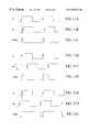
- FIG. 8are waveforms illustrating the operation of FIG. 7 .
- FIG. 9is a more detailed schematic of a portion of FIG. 5 .
- FIGS. 11A-11Iare additional waveforms and timing diagrams illustrating the operation of FIG. 5 .
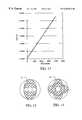
- FIG. 12is a graph illustrating the linearity of the present invention.
- FIGS. 15A, 15 B, and 15 Care plan views illustrating the detailed structure of FIG. 2 .
- FIG. 16is a side elevation view of FIG. 2 and FIGS. 15A, 15 B, and 15 C combined.
- FIG. 17is a circuit schematic of FIG. 16 .
- the axis 10includes the shaft 11 on which is mounted for rotation a coupler disk 12 (also see FIG. 3 ).
- the diskis made of an insulating material such as plastic and as illustrated in FIG. 1 is interposed between a pair of substantially circular transmit and receive disks 13 and 14 . These are fixed with respect to each other.
- FIG. 2illustrates both disks 13 and 14 which are substantially identical.
- the transmit diskconsists of six spiral loop antenna patterns designated T 1 through T 6 which are connected in a series as illustrated in FIG. 6 .
- the receive disk 13is also illustrated in FIG. 6 and has six identical spiral loop antenna patterns R 1 through R 6 with the exception that each receive coil is separately connected to a digital mixer circuit 16 a portion of which is shown.
- the transmit disk 12is driven by a signal source 17 which has a frequency, F c , of 1 MHz.
- each coil for example, R 1is divided (see FIG. 17) into four portions designated R 1 / 1 , R 1 / 2 , R 1 / 3 , and R 1 / 4 .
- These layers 1 - 4are mounted as illustrated in FIG. 16 on the transmit and receive disks 12 and 14 in a sandwich or layered type of construction.
- each transmit and receive diskactually has three laminated together subdisks. This substantially increases inductance but may not be absolutely necessary, especially if larger diameter disks are utilized.
- thisincludes a crescent-shaped symmetrical conductive pattern 21 which is carried by the insulating disk 12 .
- Other patternsmay be suitable as illustrated in FIGS. 13 and 14 as will be discussed below.
- This conducive coupler patternwhen interposed between the transmit and receive disks 13 and 14 as illustrated in FIG. 1 attenuates the inductive coupling between the disks.
- such pattern 21has a single rotary angular position of maximum attenuation where the portion 22 is exactly interposed between a pair of coils of transmit and receive disks 13 and 14 .
- the coil patterns of 13 and 14 of R 1 -R 6are identical and they are spatially mated to one another. This provides enhanced operation.
- the crescent shaped pattern 21also has a single position of minimum attenuation shown at 23 . This is of course where a minimum of attenuating conductive layer affects the inductive coupling between the transmit and receive coils.
- FIG. 4illustrates an actual curve which shows essential linearity which was achieved with this crescent shaped pattern.
- the patternis generated with respect to the axis 10 rotation and the 4 diameters designated d 1 , d 2 , d 3 , and d 4 .
- d 2is the diameter of the aperture in the coupler disk 21 . This is an inner diameter, and the outer diameter of the disk is d 1 .
- the cross-hatched area of the pattern 21is exactly equal to one-half of the area of the disk between the inner and outer diameters.
- this type of shapeprovides a substantially linearly proportionate attenuation between the maximum point 22 and the minimum 23 which is also indicated by FIG. 12, which is actually is a measured output using the pattern of FIG. 4 .
- FIG. 5is a circuit diagram illustrating the oscillator or signal source 17 which supplies a signal, F c , to the coils of transmit disk 13 , which are inductively coupled to receive disk 14 and attenuated by the rotary coupler 12 .
- the signal source 17is also connected to a digital mixer and waveform generator 16 which also has as an input 31 , the six receive coils.
- On output line 32a set (S) signal is supplied to an RS flip-flop.
- the coupler diskwill interrupt and attenuate the signal amplitudes based on the coupler pattern with respect to the position of each receiver coil, that is R 1 through R 6 , six different amplitude signals are simultaneously generated at any one angular position of the coupler.
- Sixhas been chosen as the number of channels since this will result in an improved linearity of greater than 0.5 percent. However, three channels may be suitable in some cases since this will reduce the modulator costs.
- the six signals from mixer (demodulator) 16are summed by an amplifier A 1 (see also FIG. 6) and then input to a low pass filter limiting amplifier A 2 .
- the output signal of amplifier A 2is shown in FIGS. 10 a , 10 b , 10 c , and 10 d.
- These sinusoidal waveformsrelate to four difference coupler positions (of course, only one coupler position at a time would be outputted) where phase shift varies in accordance with coupler rotation.
- the coupler positions indicated in FIGS. 10 a - 10 drepresent a zero to 90 degree angular rotation.
- the amplitude of each receive coilis attenuated according to the rotation and the amplitudes of each coil are illustrated as R 1 through R 6 .
- comparator A 3then converts these waveforms to a square wave at output 36 which drives the R input of the RS flip-flop.
- the RS flip flop outputis a pulse width modulated (PWM) output where the width of the pulse is exactly proportionate to the degree of rotation from zero to 360 degrees of the shaft 11 (FIG. 1 ).
- An active low pass filter A 4provides for a PWM to analog conversion to provide an analog voltage output as indicated. This is the voltage output that is shown in FIG. 12 .
- the rotationis indicated by a linear digital scale derived from an independent measurement source. From a practical standpoint, the rotation is tracked from zero to 355 degrees with merely 5 degrees of in determinancy.
- FIGS. 11A through 11Iillustrate the operation of the RS flip-flop and the generation of the pulse width modulated output is illustrated in FIGS. 11C, 11 F and 11 I.
- the R 1 , R 2 , and R 3 inputsare of course for different degrees of rotation.
- FIG. 11Cshows a PWM output for less than 10 degrees of rotation
- FIG. 11Fan intermediate amount of rotation
- FIG. 11Ithe output for up to 355 degrees.
- the single tapered pattern illustrated in FIG. 4provides one cycle of operation per revolution. By providing a linearly tapered trace, the peak to peak linearity error is minimized. If the coupler disk pattern 21 is not symmetrical this results in one peak being greater than the other with reference to a straight line. In other words, errors are produced in the measurement.
- FIGS. 13 and 14indicate with the cross-hatched portions alternative conductive patterns 21 ′ and 21 ′′.
- two tapered patternsare shown which will result in two cycles per revolution; in FIG. 14 four cycles per revolution.
- Each pattern 21 ′ and 21 ′′has more than one minimum and maximum.
- FIG. 9illustrates FIG. 5 in greater detail where the digital mixer and waveform generator 16 is shown with its functional components.
- a digital waveform generator 41is driven by the oscillator 17 and its signal F c .
- the local oscillator signalsdrive six mixers designed 42 a through 42 f , which have as their other inputs the six output lines 31 from receive disk 14 .
- each one of the six receive coilscorresponds to one of the phase shifted local oscillator signals.
- the actual physical orientation of the receive coils as illustrated in FIG. 2corresponds to the required phase shift of the local oscillator signals.
- the outputs of the mixers 42 a - 42 fare summed at the summing amplifier A 1 and are designated as F m (0°) and then subsequently with 60° increments.
- FIGS. 7 and 8where the digital waveform generator 41 is shown.
- the local oscillator signals LO 1 through LO 6are actually the signal source 17 , F c , plus the phase shifted signals F m .
- These squarewave type signalsare illustrated in FIG. 8 .
- F mis equal to 10 KHz
- the signals of FIG. 8are generated by a divide by M unit 46 , which is actually 10 bit decoder.
- divide by Mis substantially 100 .
- Digital mixer 47includes six individual mixers 47 a - 47 f , which have as one input the F c , signal source and the other the output of the decoder 46 to produce the local oscillator outputs illustrated.
- the number of local oscillator signalsare equal to the number of receive coils.
Landscapes
- Physics & Mathematics (AREA)
- General Physics & Mathematics (AREA)
- Measurement Of Length, Angles, Or The Like Using Electric Or Magnetic Means (AREA)
- Transmission And Conversion Of Sensor Element Output (AREA)
- Near-Field Transmission Systems (AREA)
Abstract
Description
Claims (10)
Priority Applications (8)
| Application Number | Priority Date | Filing Date | Title |
|---|---|---|---|
| US09/390,885US6304076B1 (en) | 1999-09-07 | 1999-09-07 | Angular position sensor with inductive attenuating coupler |
| AT00300592TATE390618T1 (en) | 1999-09-07 | 2000-01-27 | ROTATION ANGLE SENSOR WITH INDUCTIVE COUPLING |
| EP00300592AEP1083408B1 (en) | 1999-09-07 | 2000-01-27 | Angular position sensor with inductive attenuating coupler |
| DE60038420TDE60038420T2 (en) | 1999-09-07 | 2000-01-27 | Angle of rotation sensor with inductive coupling |
| JP2000244156AJP3621872B2 (en) | 1999-09-07 | 2000-08-11 | Angular position sensor with inductive damping coupler |
| US09/764,840US6448759B2 (en) | 1999-09-07 | 2001-01-17 | Non-contact linear position sensor for motion control applications with inductive attenuating coupler |
| US09/935,374US6520031B2 (en) | 1999-09-07 | 2001-08-22 | Non contacting torque sensor |
| JP2004027913AJP2004184426A (en) | 1999-09-07 | 2004-02-04 | Angular position sensor equipped with inductive attenuation coupler |
Applications Claiming Priority (1)
| Application Number | Priority Date | Filing Date | Title |
|---|---|---|---|
| US09/390,885US6304076B1 (en) | 1999-09-07 | 1999-09-07 | Angular position sensor with inductive attenuating coupler |
Related Child Applications (2)
| Application Number | Title | Priority Date | Filing Date |
|---|---|---|---|
| US52708800AContinuation-In-Part | 1999-09-07 | 2000-03-16 | |
| US09/764,840Continuation-In-PartUS6448759B2 (en) | 1999-09-07 | 2001-01-17 | Non-contact linear position sensor for motion control applications with inductive attenuating coupler |
Publications (1)
| Publication Number | Publication Date |
|---|---|
| US6304076B1true US6304076B1 (en) | 2001-10-16 |
Family
ID=23544354
Family Applications (1)
| Application Number | Title | Priority Date | Filing Date |
|---|---|---|---|
| US09/390,885Expired - LifetimeUS6304076B1 (en) | 1999-09-07 | 1999-09-07 | Angular position sensor with inductive attenuating coupler |
Country Status (5)
| Country | Link |
|---|---|
| US (1) | US6304076B1 (en) |
| EP (1) | EP1083408B1 (en) |
| JP (2) | JP3621872B2 (en) |
| AT (1) | ATE390618T1 (en) |
| DE (1) | DE60038420T2 (en) |
Cited By (63)
| Publication number | Priority date | Publication date | Assignee | Title |
|---|---|---|---|---|
| US6522128B1 (en)* | 1997-10-15 | 2003-02-18 | Synaptics (Uk) Limited | Position sensor having compact arrangement of coils |
| US6520031B2 (en)* | 1999-09-07 | 2003-02-18 | Bei Sensors & Systems Company, Inc. | Non contacting torque sensor |
| US20030085700A1 (en)* | 2001-10-26 | 2003-05-08 | Shogo Momose | Magnetic displacement sensor device and method for detecting displacements |
| US6584428B1 (en)* | 1999-06-15 | 2003-06-24 | Hella Kg Hueck & Co. | Position sensor for a motor vehicle |
| US6593730B2 (en)* | 2000-02-01 | 2003-07-15 | Cherry Gmbh | Position sensor |
| US20030132761A1 (en)* | 2001-12-07 | 2003-07-17 | Norman Poirier | Phase angle determining circuit |
| US20030229404A1 (en)* | 1999-12-10 | 2003-12-11 | Howard Mark A. | Man-machine interface |
| US20040007663A1 (en)* | 2000-08-31 | 2004-01-15 | Siegbert Steinlechner | Method for determining a rotation angle and/or an angle differential from phase signals |
| US20040031881A1 (en)* | 2000-10-13 | 2004-02-19 | Jamgarov Stephan Grigoryevich | Aircraft provided with carrying fuselage |
| US6747448B2 (en)* | 2002-08-14 | 2004-06-08 | Honeywell International Inc. | Rotary position sensor methods and systems |
| US20050024044A1 (en)* | 2002-07-26 | 2005-02-03 | Norman Poirier | Angular positioning sensing system and method |
| US20050103308A1 (en)* | 2002-03-06 | 2005-05-19 | Borgwarner Inc. | Assembly with non-contacting position sensor |
| US20050183695A1 (en)* | 2002-03-06 | 2005-08-25 | Borgwarner Inc. | Position sensor apparatus and method |
| US20050212577A1 (en)* | 2004-03-29 | 2005-09-29 | Madni Asad M | Programmable, multi-turn, pulse width modulation circuit for a non-contact angular position sensor |
| US20050225320A1 (en)* | 2004-04-09 | 2005-10-13 | Lee Joong K | Inductive position sensor |
| US20050275568A1 (en)* | 2004-05-25 | 2005-12-15 | Madni Asad M | Pulse width modulation based digital incremental encoder |
| EP1647816A1 (en) | 2004-10-15 | 2006-04-19 | Bei Sensors And Systems Company, Inc. | Digitally compensated non-contact steering angle and torque sensor |
| US20060116822A1 (en)* | 2003-10-01 | 2006-06-01 | Axel Wenzler | Method and circuit arrangement for detemining a quality level of phase signals |
| US7133793B2 (en) | 2003-07-24 | 2006-11-07 | Synaptics (Uk) Limited | Magnetic calibration array |
| US20070001666A1 (en)* | 2005-06-27 | 2007-01-04 | Lee Joong K | Linear and rotational inductive position sensor |
| US7221154B2 (en) | 2005-04-07 | 2007-05-22 | Ksr International Co. | Inductive position sensor with common mode corrective winding and simplified signal conditioning |
| US20070132449A1 (en)* | 2005-12-08 | 2007-06-14 | Madni Asad M | Multi-turn non-contact angular position sensor |
| US7292026B2 (en) | 2005-04-08 | 2007-11-06 | Ksr International Co. | Signal conditioning system for inductive position sensor |
| US20080054887A1 (en)* | 2004-04-09 | 2008-03-06 | Lee Joong K | Inductive position sensor |
| US7406393B2 (en) | 2002-03-05 | 2008-07-29 | Synaptics (Uk) Limited | Position sensor |
| WO2008087545A3 (en)* | 2007-01-19 | 2008-10-23 | Ksr Tech Co | Induction position sensor using reference signal |
| CN100445694C (en)* | 2004-04-09 | 2008-12-24 | Ksr科技公司 | inductive position sensor |
| US7511705B2 (en) | 2001-05-21 | 2009-03-31 | Synaptics (Uk) Limited | Position sensor |
| WO2009037561A3 (en)* | 2007-09-21 | 2009-06-11 | Ksr Tech Co | Inductive position sensor |
| US20090224752A1 (en)* | 2008-03-07 | 2009-09-10 | Mikhail Rakov | Reactance sensors of radial position for magnetic bearings and bearingless drives |
| US7812268B2 (en) | 2003-08-26 | 2010-10-12 | Synaptics (Uk) Limited | Digitizer system |
| US7907130B2 (en) | 2002-06-05 | 2011-03-15 | Synaptics (Uk) Limited | Signal transfer method and apparatus |
| US20110109304A1 (en)* | 2009-11-09 | 2011-05-12 | Aisan Kogyo Kabushiki Kaisha | Rotation angle sensor |
| US20120242352A1 (en)* | 2011-02-22 | 2012-09-27 | Rockwell Automation Asia Pacific Business Center Pte. Ltd. | Inductive proximity sensor |
| US8570028B2 (en) | 2007-05-10 | 2013-10-29 | Cambridge Integrated Circuits Limited | Transducer for a position sensor |
| RU2502046C1 (en)* | 2012-08-07 | 2013-12-20 | Открытое акционерное общество "Авангард" | Induction sensor of angular position |
| US20140132252A1 (en)* | 2012-11-12 | 2014-05-15 | Mitsubishi Heavy Industries, Ltd. | Wiring structure of displacement sensor |
| RU2570232C1 (en)* | 2014-09-09 | 2015-12-10 | Открытое акционерное общество "Авангард" | Induction angular position sensor |
| US9285386B2 (en) | 2013-12-06 | 2016-03-15 | Rosemount Aerospace Inc. | Inductive rotational speed sensors |
| US9410791B2 (en) | 2010-12-24 | 2016-08-09 | Cambridge Integrated Circuits Limited | Position sensing transducer |
| US9470505B2 (en) | 2012-06-13 | 2016-10-18 | Cambridge Integrated Circuits Limited | Position sensing transducer |
| CN109073416A (en)* | 2016-02-24 | 2018-12-21 | 罗伯特·博世有限公司 | Angular sensor |
| WO2019014690A1 (en) | 2017-07-13 | 2019-01-17 | Azoteq (Pty) Ltd | Inductive sensing user interface devices |
| US10275055B2 (en) | 2016-03-31 | 2019-04-30 | Azoteq (Pty) Ltd | Rotational sensing |
| WO2019089073A1 (en)* | 2017-11-02 | 2019-05-09 | Ksr Ip Holdings Llc. | Duty cycle for inductive position sensors |
| EP3514501A1 (en)* | 2018-01-22 | 2019-07-24 | Melexis Technologies SA | Flux coupling sensor |
| US20190226828A1 (en)* | 2018-01-22 | 2019-07-25 | Melexis Technologies Sa | Inductive position sensor |
| US10415952B2 (en) | 2016-10-28 | 2019-09-17 | Microsemi Corporation | Angular position sensor and associated method of use |
| US10527457B2 (en) | 2015-02-27 | 2020-01-07 | Azoteq (Pty) Ltd | Inductance sensing |
| US10837847B2 (en) | 2018-10-05 | 2020-11-17 | Microsemi Corporation | Angular rotation sensor |
| US10921155B2 (en) | 2018-02-02 | 2021-02-16 | Microsemi Corporation | Multi cycle dual redundant angular position sensing mechanism and associated method of use for precise angular displacement measurement |
| US11125591B2 (en)* | 2017-08-15 | 2021-09-21 | KSR IP Holdings, LLC | Systems and methods for correcting non-sinusoidal signals generated from non-circular couplers |
| US11519752B2 (en)* | 2018-09-14 | 2022-12-06 | KSR IP Holdings, LLC | Coupler element shapes for inductive position sensors |
| US11525701B2 (en) | 2018-01-22 | 2022-12-13 | Melexis Technologies Sa | Inductive position sensor |
| US11656100B2 (en) | 2020-10-08 | 2023-05-23 | Pulse Innovation Labs, Inc. | Angular displacement sensor |
| US11898887B2 (en) | 2021-03-25 | 2024-02-13 | Microchip Technology Incorporated | Sense coil for inductive rotational-position sensing, and related devices, systems, and methods |
| US12031817B2 (en) | 2021-08-05 | 2024-07-09 | Microchip Technology Incorporated | Inductive angular-position sensors, and related devices, systems, and methods |
| WO2024201355A1 (en) | 2023-03-28 | 2024-10-03 | Nunes Dos Santos Cabral Jorge Miguel | Inductive position sensor and obtaining process thereof |
| US12111188B2 (en) | 2021-06-11 | 2024-10-08 | Microchip Technology Incorporated | Sense coil for inductive linear-position sensing, and related devices, systems, and methods |
| US12203780B2 (en) | 2022-04-01 | 2025-01-21 | Microchip Technology Incorporated | Target for an inductive angular-position sensor |
| US12244183B2 (en) | 2021-09-21 | 2025-03-04 | Advanced Automation Group | Angle sensor device |
| US12339139B2 (en) | 2021-09-28 | 2025-06-24 | Microchip Technology Incorporated | Angular-position sensor |
| US12411001B2 (en) | 2022-04-01 | 2025-09-09 | Microchip Technology Incorporated | Target for inductive angular-position sensing |
Families Citing this family (17)
| Publication number | Priority date | Publication date | Assignee | Title |
|---|---|---|---|---|
| US6448759B2 (en)* | 1999-09-07 | 2002-09-10 | Bei Sensors And Systems Company, Inc. | Non-contact linear position sensor for motion control applications with inductive attenuating coupler |
| JP4654365B2 (en)* | 2006-08-31 | 2011-03-16 | 多摩川精機株式会社 | Linear differential transformer |
| DE102007015524A1 (en)* | 2007-03-30 | 2008-10-09 | Cherry Gmbh | Method for producing an inductive damping element and inductive eddy current actuating element |
| DE102007037216B4 (en) | 2007-08-07 | 2023-01-19 | Robert Bosch Gmbh | Measuring device for non-contact detection of a relative position |
| US7911354B2 (en)* | 2007-12-12 | 2011-03-22 | Ksr Technologies Co. | Inductive position sensor |
| KR100929163B1 (en)* | 2008-03-20 | 2009-12-01 | 주식회사 트루윈 | Inductance angle sensor with improved noise resistance and signal processing method |
| EP2350569B1 (en) | 2009-08-28 | 2016-08-10 | Truwin Co., Ltd | Inductive angle sensor with improved common mode noise rejection and signal processing method of the same |
| US8508242B2 (en)* | 2010-01-25 | 2013-08-13 | Ksr Technologies Co. | Inductive position sensor |
| DE102012223037A1 (en)* | 2012-12-13 | 2014-06-18 | Dr. Johannes Heidenhain Gmbh | Inductive position measuring device |
| EP2936097A1 (en)* | 2012-12-21 | 2015-10-28 | Continental Teves AG & Co. oHG | Method for detecting a torque applied to a shaft |
| CZ2013205A3 (en) | 2013-03-22 | 2014-10-22 | Rieter Cz S.R.O. | Device for detecting position of rotating working means in active magnetic bearing |
| CN104217836A (en)* | 2014-09-04 | 2014-12-17 | 天津大学 | Coil structure of angle transducer based on electromagnetic induction |
| DE102014220454A1 (en)* | 2014-10-09 | 2016-04-14 | Robert Bosch Gmbh | Sensor arrangement for the contactless detection of angles of rotation on a rotating component |
| DE102016217255A1 (en) | 2016-09-09 | 2018-03-15 | Robert Bosch Gmbh | Angle of rotation sensor and stator for this |
| DE112019004235T5 (en) | 2018-08-24 | 2021-05-27 | KSR IP Holdings, LLC | Inductive angle position sensor on one shaft end with a metal-ferrite complementary coupler |
| DE102020119985A1 (en) | 2020-07-29 | 2022-02-03 | Samson Aktiengesellschaft | Position sensor for determining the position of a valve stem of a control valve |
| CN115508576B (en)* | 2022-11-22 | 2023-03-24 | 天津赛恩能源技术股份有限公司 | Excitation adjusting method |
Citations (5)
| Publication number | Priority date | Publication date | Assignee | Title |
|---|---|---|---|---|
| US4737698A (en)* | 1984-10-19 | 1988-04-12 | Kollmorgan Technologies Corporation | Position and speed sensors |
| US4986124A (en) | 1987-06-15 | 1991-01-22 | Kollmorgen Corporation | Screened inductance sensors, especially sensors for level measurement |
| US5239288A (en)* | 1990-03-09 | 1993-08-24 | Transicoil Inc. | Resolver having planar windings |
| US5406155A (en)* | 1992-06-03 | 1995-04-11 | Trw Inc. | Method and apparatus for sensing relative position between two relatively rotatable members |
| US5767670A (en)* | 1996-08-29 | 1998-06-16 | Texas Instruments Incorporated | Method and apparatus for providing improved temperature compensated output for variable differential transformer system |
Family Cites Families (3)
| Publication number | Priority date | Publication date | Assignee | Title |
|---|---|---|---|---|
| DE1588220A1 (en)* | 1967-01-23 | 1970-10-22 | Grundig Emv | Device for detecting a specific position in moving parts by inductive scanning |
| DE9105145U1 (en)* | 1991-04-26 | 1992-08-27 | Papst-Motoren GmbH & Co KG, 7742 St Georgen | Position sensor for rotary movements |
| EP0743508A2 (en)* | 1995-05-16 | 1996-11-20 | Mitutoyo Corporation | Induced current position transducer |
- 1999
- 1999-09-07USUS09/390,885patent/US6304076B1/ennot_activeExpired - Lifetime
- 2000
- 2000-01-27ATAT00300592Tpatent/ATE390618T1/ennot_activeIP Right Cessation
- 2000-01-27EPEP00300592Apatent/EP1083408B1/ennot_activeExpired - Lifetime
- 2000-01-27DEDE60038420Tpatent/DE60038420T2/ennot_activeExpired - Fee Related
- 2000-08-11JPJP2000244156Apatent/JP3621872B2/ennot_activeExpired - Fee Related
- 2004
- 2004-02-04JPJP2004027913Apatent/JP2004184426A/enactivePending
Patent Citations (5)
| Publication number | Priority date | Publication date | Assignee | Title |
|---|---|---|---|---|
| US4737698A (en)* | 1984-10-19 | 1988-04-12 | Kollmorgan Technologies Corporation | Position and speed sensors |
| US4986124A (en) | 1987-06-15 | 1991-01-22 | Kollmorgen Corporation | Screened inductance sensors, especially sensors for level measurement |
| US5239288A (en)* | 1990-03-09 | 1993-08-24 | Transicoil Inc. | Resolver having planar windings |
| US5406155A (en)* | 1992-06-03 | 1995-04-11 | Trw Inc. | Method and apparatus for sensing relative position between two relatively rotatable members |
| US5767670A (en)* | 1996-08-29 | 1998-06-16 | Texas Instruments Incorporated | Method and apparatus for providing improved temperature compensated output for variable differential transformer system |
Cited By (104)
| Publication number | Priority date | Publication date | Assignee | Title |
|---|---|---|---|---|
| US6522128B1 (en)* | 1997-10-15 | 2003-02-18 | Synaptics (Uk) Limited | Position sensor having compact arrangement of coils |
| US6584428B1 (en)* | 1999-06-15 | 2003-06-24 | Hella Kg Hueck & Co. | Position sensor for a motor vehicle |
| US6520031B2 (en)* | 1999-09-07 | 2003-02-18 | Bei Sensors & Systems Company, Inc. | Non contacting torque sensor |
| US20030229404A1 (en)* | 1999-12-10 | 2003-12-11 | Howard Mark A. | Man-machine interface |
| US6593730B2 (en)* | 2000-02-01 | 2003-07-15 | Cherry Gmbh | Position sensor |
| US20040007663A1 (en)* | 2000-08-31 | 2004-01-15 | Siegbert Steinlechner | Method for determining a rotation angle and/or an angle differential from phase signals |
| US6761075B2 (en)* | 2000-08-31 | 2004-07-13 | Robert Bosch Gmbh | Method for determining a rotation angle and/or an angle differential from phase signals |
| AU2001291619B2 (en)* | 2000-08-31 | 2006-06-01 | Robert Bosch Gmbh | Method for determining a rotational angle and/or an angle differential from phase signals |
| US20040031881A1 (en)* | 2000-10-13 | 2004-02-19 | Jamgarov Stephan Grigoryevich | Aircraft provided with carrying fuselage |
| US8243033B2 (en) | 2001-05-21 | 2012-08-14 | Synaptics (Uk) Limited | Position sensor |
| US7511705B2 (en) | 2001-05-21 | 2009-03-31 | Synaptics (Uk) Limited | Position sensor |
| US20030085700A1 (en)* | 2001-10-26 | 2003-05-08 | Shogo Momose | Magnetic displacement sensor device and method for detecting displacements |
| US20030132761A1 (en)* | 2001-12-07 | 2003-07-17 | Norman Poirier | Phase angle determining circuit |
| US7098653B2 (en)* | 2001-12-07 | 2006-08-29 | Stoneridge Control Devices, Inc. | Phase angle determining circuit |
| US7406393B2 (en) | 2002-03-05 | 2008-07-29 | Synaptics (Uk) Limited | Position sensor |
| US20050103308A1 (en)* | 2002-03-06 | 2005-05-19 | Borgwarner Inc. | Assembly with non-contacting position sensor |
| US20050183695A1 (en)* | 2002-03-06 | 2005-08-25 | Borgwarner Inc. | Position sensor apparatus and method |
| US20070113824A1 (en)* | 2002-03-06 | 2007-05-24 | Borgwarner Inc. | Assembly with non-contacting position sensor |
| US20070113825A1 (en)* | 2002-03-06 | 2007-05-24 | Borgwarner Inc. | Position sensor apparatus and method |
| US7191754B2 (en)* | 2002-03-06 | 2007-03-20 | Borgwarner Inc. | Position sensor apparatus and method |
| US7182063B2 (en)* | 2002-03-06 | 2007-02-27 | Borgwarner Inc. | Assembly with non-contacting position sensor |
| US7594494B2 (en) | 2002-03-06 | 2009-09-29 | Borgwarner Inc. | Assembly with non-contacting position sensor |
| US7907130B2 (en) | 2002-06-05 | 2011-03-15 | Synaptics (Uk) Limited | Signal transfer method and apparatus |
| US20050024044A1 (en)* | 2002-07-26 | 2005-02-03 | Norman Poirier | Angular positioning sensing system and method |
| US6747448B2 (en)* | 2002-08-14 | 2004-06-08 | Honeywell International Inc. | Rotary position sensor methods and systems |
| US7133793B2 (en) | 2003-07-24 | 2006-11-07 | Synaptics (Uk) Limited | Magnetic calibration array |
| US7812268B2 (en) | 2003-08-26 | 2010-10-12 | Synaptics (Uk) Limited | Digitizer system |
| US8022317B2 (en) | 2003-08-26 | 2011-09-20 | Synaptics (Uk) Limited | Digitizer system |
| US7340345B2 (en)* | 2003-10-01 | 2008-03-04 | Robert Bosch Gmbh | Method and circuit arrangement for determining a quality level of phase signals |
| US20060116822A1 (en)* | 2003-10-01 | 2006-06-01 | Axel Wenzler | Method and circuit arrangement for detemining a quality level of phase signals |
| US20050212577A1 (en)* | 2004-03-29 | 2005-09-29 | Madni Asad M | Programmable, multi-turn, pulse width modulation circuit for a non-contact angular position sensor |
| US6985018B2 (en) | 2004-03-29 | 2006-01-10 | Bei Sensors & Systems Company, Inc. | Programmable, multi-turn, pulse width modulation circuit for a non-contact angular position sensor |
| WO2005098370A1 (en)* | 2004-04-09 | 2005-10-20 | Ksr International Co. | Inductive position sensor |
| US7276897B2 (en) | 2004-04-09 | 2007-10-02 | Ksr International Co. | Inductive position sensor |
| US7538544B2 (en) | 2004-04-09 | 2009-05-26 | Ksr Technologies Co. | Inductive position sensor |
| US20080054887A1 (en)* | 2004-04-09 | 2008-03-06 | Lee Joong K | Inductive position sensor |
| US20050225320A1 (en)* | 2004-04-09 | 2005-10-13 | Lee Joong K | Inductive position sensor |
| CN100445694C (en)* | 2004-04-09 | 2008-12-24 | Ksr科技公司 | inductive position sensor |
| US7015832B2 (en) | 2004-05-25 | 2006-03-21 | Bei Sensors & Systems Company, Inc. | Pulse width modulation based digital incremental encoder |
| US20050275568A1 (en)* | 2004-05-25 | 2005-12-15 | Madni Asad M | Pulse width modulation based digital incremental encoder |
| EP1647816A1 (en) | 2004-10-15 | 2006-04-19 | Bei Sensors And Systems Company, Inc. | Digitally compensated non-contact steering angle and torque sensor |
| US7345473B2 (en) | 2005-04-07 | 2008-03-18 | Ksr Technologies Co. | Inductive position sensor with common mode corrective winding and simplified signal conditioning |
| US7221154B2 (en) | 2005-04-07 | 2007-05-22 | Ksr International Co. | Inductive position sensor with common mode corrective winding and simplified signal conditioning |
| CN101194144B (en)* | 2005-04-07 | 2010-06-23 | Ksr科技公司 | Inductive position sensor with common mode corrective winding and simplified signal conditioning |
| KR100844521B1 (en)* | 2005-04-07 | 2008-07-09 | 케이에스알 테크놀로지즈 컴퍼니 | Apparatus for providing an output signal correlated with the position of a part having a position range relative to the moving part and a method of determining the position of the moving part |
| US20070194782A1 (en)* | 2005-04-07 | 2007-08-23 | Lee Joong K | Inductive position sensor with common mode corrective winding and simplified signal conditioning |
| WO2006106421A3 (en)* | 2005-04-07 | 2008-01-03 | Ksr Int Co | Inductive position sensor with common mode corrective winding and simplified signal conditioning |
| US7292026B2 (en) | 2005-04-08 | 2007-11-06 | Ksr International Co. | Signal conditioning system for inductive position sensor |
| US20100141245A1 (en)* | 2005-06-27 | 2010-06-10 | Lee Joong K | Linear and rotational inductive position sensor |
| US7821256B2 (en) | 2005-06-27 | 2010-10-26 | Ksr Technologies Co. | Linear and rotational inductive position sensor |
| US8350561B2 (en) | 2005-06-27 | 2013-01-08 | Ksr Technologies Co. | Linear and rotational inductive position sensor |
| US20070001666A1 (en)* | 2005-06-27 | 2007-01-04 | Lee Joong K | Linear and rotational inductive position sensor |
| CN101253390B (en)* | 2005-06-27 | 2010-06-16 | Ksr科技公司 | Linear rotary induction type position sensor |
| US7449878B2 (en) | 2005-06-27 | 2008-11-11 | Ksr Technologies Co. | Linear and rotational inductive position sensor |
| WO2007000653A1 (en)* | 2005-06-27 | 2007-01-04 | Ksr Technologies Co. | Linear and rotational inductive position sensor |
| US20070132449A1 (en)* | 2005-12-08 | 2007-06-14 | Madni Asad M | Multi-turn non-contact angular position sensor |
| WO2008087545A3 (en)* | 2007-01-19 | 2008-10-23 | Ksr Tech Co | Induction position sensor using reference signal |
| US7482803B2 (en) | 2007-01-19 | 2009-01-27 | Ksr Technologies Co. | Inductive position sensor using reference signal |
| US8570028B2 (en) | 2007-05-10 | 2013-10-29 | Cambridge Integrated Circuits Limited | Transducer for a position sensor |
| CN101868695A (en)* | 2007-09-21 | 2010-10-20 | Ksr科技公司 | Inductive position sensor |
| WO2009037561A3 (en)* | 2007-09-21 | 2009-06-11 | Ksr Tech Co | Inductive position sensor |
| CN101868695B (en)* | 2007-09-21 | 2013-03-06 | Ksr科技公司 | Inductive position sensor |
| US20090224752A1 (en)* | 2008-03-07 | 2009-09-10 | Mikhail Rakov | Reactance sensors of radial position for magnetic bearings and bearingless drives |
| US8299781B2 (en)* | 2008-03-07 | 2012-10-30 | Minebea Co., Ltd. | Reactance sensors of radial position for magnetic bearings and bearingless drives |
| US8729887B2 (en) | 2009-11-09 | 2014-05-20 | Aisan Kogyo Kabushiki Kaisha | Rotation angle sensor |
| US20110109304A1 (en)* | 2009-11-09 | 2011-05-12 | Aisan Kogyo Kabushiki Kaisha | Rotation angle sensor |
| US9410791B2 (en) | 2010-12-24 | 2016-08-09 | Cambridge Integrated Circuits Limited | Position sensing transducer |
| US20120242352A1 (en)* | 2011-02-22 | 2012-09-27 | Rockwell Automation Asia Pacific Business Center Pte. Ltd. | Inductive proximity sensor |
| US9007071B2 (en)* | 2011-02-22 | 2015-04-14 | Rockwell Automation Technologies, Inc. | Inductive proximity sensor |
| US9470505B2 (en) | 2012-06-13 | 2016-10-18 | Cambridge Integrated Circuits Limited | Position sensing transducer |
| RU2502046C1 (en)* | 2012-08-07 | 2013-12-20 | Открытое акционерное общество "Авангард" | Induction sensor of angular position |
| US20140132252A1 (en)* | 2012-11-12 | 2014-05-15 | Mitsubishi Heavy Industries, Ltd. | Wiring structure of displacement sensor |
| US9285386B2 (en) | 2013-12-06 | 2016-03-15 | Rosemount Aerospace Inc. | Inductive rotational speed sensors |
| RU2570232C1 (en)* | 2014-09-09 | 2015-12-10 | Открытое акционерное общество "Авангард" | Induction angular position sensor |
| US10527457B2 (en) | 2015-02-27 | 2020-01-07 | Azoteq (Pty) Ltd | Inductance sensing |
| US20190025088A1 (en)* | 2016-02-24 | 2019-01-24 | Robert Bosch Gmbh | Rotational Angle Sensor |
| CN109073416A (en)* | 2016-02-24 | 2018-12-21 | 罗伯特·博世有限公司 | Angular sensor |
| US10907992B2 (en)* | 2016-02-24 | 2021-02-02 | Robert Bosch Gmbh | Rotational angle sensor |
| CN109073416B (en)* | 2016-02-24 | 2020-05-26 | 罗伯特·博世有限公司 | Rotation angle sensor |
| US10275055B2 (en) | 2016-03-31 | 2019-04-30 | Azoteq (Pty) Ltd | Rotational sensing |
| US10415952B2 (en) | 2016-10-28 | 2019-09-17 | Microsemi Corporation | Angular position sensor and associated method of use |
| US11624633B2 (en) | 2017-07-13 | 2023-04-11 | Azoteq Holdings Limited | Inductive sensing user interface devices |
| WO2019014690A1 (en) | 2017-07-13 | 2019-01-17 | Azoteq (Pty) Ltd | Inductive sensing user interface devices |
| US11125591B2 (en)* | 2017-08-15 | 2021-09-21 | KSR IP Holdings, LLC | Systems and methods for correcting non-sinusoidal signals generated from non-circular couplers |
| WO2019089073A1 (en)* | 2017-11-02 | 2019-05-09 | Ksr Ip Holdings Llc. | Duty cycle for inductive position sensors |
| US11644343B2 (en) | 2018-01-22 | 2023-05-09 | Melexis Technologies Sa | Flux coupling sensor |
| WO2019141854A1 (en)* | 2018-01-22 | 2019-07-25 | Melexis Technologies Sa | Flux coupling sensor |
| US20190226828A1 (en)* | 2018-01-22 | 2019-07-25 | Melexis Technologies Sa | Inductive position sensor |
| US11002568B2 (en)* | 2018-01-22 | 2021-05-11 | Melexis Technologies Sa | Inductive position sensor |
| EP3514501A1 (en)* | 2018-01-22 | 2019-07-24 | Melexis Technologies SA | Flux coupling sensor |
| US11525701B2 (en) | 2018-01-22 | 2022-12-13 | Melexis Technologies Sa | Inductive position sensor |
| US10845215B2 (en)* | 2018-01-22 | 2020-11-24 | Melexis Technologies Sa | Inductive position sensor |
| US10921155B2 (en) | 2018-02-02 | 2021-02-16 | Microsemi Corporation | Multi cycle dual redundant angular position sensing mechanism and associated method of use for precise angular displacement measurement |
| US11519752B2 (en)* | 2018-09-14 | 2022-12-06 | KSR IP Holdings, LLC | Coupler element shapes for inductive position sensors |
| US10837847B2 (en) | 2018-10-05 | 2020-11-17 | Microsemi Corporation | Angular rotation sensor |
| US11656100B2 (en) | 2020-10-08 | 2023-05-23 | Pulse Innovation Labs, Inc. | Angular displacement sensor |
| US11898887B2 (en) | 2021-03-25 | 2024-02-13 | Microchip Technology Incorporated | Sense coil for inductive rotational-position sensing, and related devices, systems, and methods |
| US12111188B2 (en) | 2021-06-11 | 2024-10-08 | Microchip Technology Incorporated | Sense coil for inductive linear-position sensing, and related devices, systems, and methods |
| US12031817B2 (en) | 2021-08-05 | 2024-07-09 | Microchip Technology Incorporated | Inductive angular-position sensors, and related devices, systems, and methods |
| US12244183B2 (en) | 2021-09-21 | 2025-03-04 | Advanced Automation Group | Angle sensor device |
| US12339139B2 (en) | 2021-09-28 | 2025-06-24 | Microchip Technology Incorporated | Angular-position sensor |
| US12203780B2 (en) | 2022-04-01 | 2025-01-21 | Microchip Technology Incorporated | Target for an inductive angular-position sensor |
| US12411001B2 (en) | 2022-04-01 | 2025-09-09 | Microchip Technology Incorporated | Target for inductive angular-position sensing |
| WO2024201355A1 (en) | 2023-03-28 | 2024-10-03 | Nunes Dos Santos Cabral Jorge Miguel | Inductive position sensor and obtaining process thereof |
Also Published As
| Publication number | Publication date |
|---|---|
| ATE390618T1 (en) | 2008-04-15 |
| DE60038420D1 (en) | 2008-05-08 |
| DE60038420T2 (en) | 2009-04-09 |
| JP3621872B2 (en) | 2005-02-16 |
| JP2001082915A (en) | 2001-03-30 |
| EP1083408A3 (en) | 2003-05-07 |
| JP2004184426A (en) | 2004-07-02 |
| EP1083408A2 (en) | 2001-03-14 |
| EP1083408B1 (en) | 2008-03-26 |
Similar Documents
| Publication | Publication Date | Title |
|---|---|---|
| US6304076B1 (en) | Angular position sensor with inductive attenuating coupler | |
| US6520031B2 (en) | Non contacting torque sensor | |
| US6448759B2 (en) | Non-contact linear position sensor for motion control applications with inductive attenuating coupler | |
| EP1795871A1 (en) | Multi-turn non-contact angular position sensor | |
| EP1078226B1 (en) | Position sensor | |
| US3812481A (en) | Non-contacting electrical rotary position and rotation transducer | |
| US6259249B1 (en) | Induction-type position measuring apparatus | |
| KR101904862B1 (en) | Rotary position sensor | |
| CN102016513B (en) | Rotation angle detection device | |
| WO2003071232A1 (en) | Pulsed torque, force or general measurement with a coil and a magnetic field sensor (tangentially, circumferentially | |
| US20160091343A1 (en) | Robust rotary encoder for power tool | |
| US11287338B2 (en) | Torque measurement using millimeter-wave metamaterial | |
| US12270689B2 (en) | Position sensor and position encoder using millimeter-wave metamaterial with a millimeter-wave radar | |
| CN113008129B (en) | Multi-turn absolute time grating angular displacement sensor | |
| WO2022124415A1 (en) | Resolver | |
| JP3940140B2 (en) | Multi-turn PWM generator, multi-turn angular position sensor, and method for generating a multi-turn pulse width modulated signal | |
| JPH0743266B2 (en) | Capacitive position transducer | |
| JPH07244157A (en) | Distance measuring system between two movable stations | |
| US20210102854A1 (en) | Torque measurement using millimeter-wave metamaterial | |
| EP1134567A1 (en) | Non contacting torque sensor | |
| US20060023777A1 (en) | Signal transmission | |
| CN217690043U (en) | Electromagnetic encoder and electromagnetic handwriting device | |
| WO2023037154A1 (en) | Rotational sensor | |
| WO2022124411A1 (en) | Resolver | |
| JPH04264210A (en) | Rotational displacement angle detection device |
Legal Events
| Date | Code | Title | Description |
|---|---|---|---|
| AS | Assignment | Owner name:BEI SENSORS & SYSTEMS COMPANY, INC., CALIFORNIA Free format text:ASSIGNMENT OF ASSIGNORS INTEREST;ASSIGNORS:MADNI, ASAD M.;VUONG, JIM B.;REEL/FRAME:010228/0755 Effective date:19990830 | |
| STCF | Information on status: patent grant | Free format text:PATENTED CASE | |
| FPAY | Fee payment | Year of fee payment:4 | |
| FPAY | Fee payment | Year of fee payment:8 | |
| FPAY | Fee payment | Year of fee payment:12 | |
| AS | Assignment | Owner name:DEUTSCHE BANK AG NEW YORK BRANCH, AS COLLATERAL AG Free format text:SECURITY AGREEMENT;ASSIGNORS:BEI SENSORS & SYSTEMS COMPANY, INC.;CUSTOM SENSORS & TECHNOLOGIES, INC;CRYDOM, INC.;AND OTHERS;REEL/FRAME:033888/0700 Effective date:20140930 | |
| AS | Assignment | Owner name:BEI SENSORS & SYSTEMS COMPANY, INC., CALIFORNIA Free format text:RELEASE BY SECURED PARTY;ASSIGNOR:DEUTSCHE BANK AG NEW YORK BRANCH;REEL/FRAME:037196/0174 Effective date:20151201 Owner name:CUSTOM SENSORS & TECHNOLOGIES, INC., CALIFORNIA Free format text:RELEASE BY SECURED PARTY;ASSIGNOR:DEUTSCHE BANK AG NEW YORK BRANCH;REEL/FRAME:037196/0174 Effective date:20151201 Owner name:BEI TECHNOLOGIES, INC., CALIFORNIA Free format text:RELEASE BY SECURED PARTY;ASSIGNOR:DEUTSCHE BANK AG NEW YORK BRANCH;REEL/FRAME:037196/0174 Effective date:20151201 Owner name:KAVLICO CORPORATION, CALIFORNIA Free format text:RELEASE BY SECURED PARTY;ASSIGNOR:DEUTSCHE BANK AG NEW YORK BRANCH;REEL/FRAME:037196/0174 Effective date:20151201 Owner name:CRYDOM, INC., CALIFORNIA Free format text:RELEASE BY SECURED PARTY;ASSIGNOR:DEUTSCHE BANK AG NEW YORK BRANCH;REEL/FRAME:037196/0174 Effective date:20151201 | |
| AS | Assignment | Owner name:MORGAN STANLEY SENIOR FUNDING, INC., NEW YORK Free format text:SECURITY INTEREST;ASSIGNORS:BEI NORTH AMERICA LLC;CRYDOM, INC.;CUSTOM SENSORS & TECHNOLOGIES, INC.;AND OTHERS;REEL/FRAME:037927/0605 Effective date:20160224 |