US6302965B1 - Dispersion plate for flowing vaporizes compounds used in chemical vapor deposition of films onto semiconductor surfaces - Google Patents
Dispersion plate for flowing vaporizes compounds used in chemical vapor deposition of films onto semiconductor surfacesDownload PDFInfo
- Publication number
- US6302965B1 US6302965B1US09/638,506US63850600AUS6302965B1US 6302965 B1US6302965 B1US 6302965B1US 63850600 AUS63850600 AUS 63850600AUS 6302965 B1US6302965 B1US 6302965B1
- Authority
- US
- United States
- Prior art keywords
- passages
- plate
- center axis
- diameter
- face
- Prior art date
- Legal status (The legal status is an assumption and is not a legal conclusion. Google has not performed a legal analysis and makes no representation as to the accuracy of the status listed.)
- Expired - Fee Related
Links
Images


Classifications
- C—CHEMISTRY; METALLURGY
- C23—COATING METALLIC MATERIAL; COATING MATERIAL WITH METALLIC MATERIAL; CHEMICAL SURFACE TREATMENT; DIFFUSION TREATMENT OF METALLIC MATERIAL; COATING BY VACUUM EVAPORATION, BY SPUTTERING, BY ION IMPLANTATION OR BY CHEMICAL VAPOUR DEPOSITION, IN GENERAL; INHIBITING CORROSION OF METALLIC MATERIAL OR INCRUSTATION IN GENERAL
- C23C—COATING METALLIC MATERIAL; COATING MATERIAL WITH METALLIC MATERIAL; SURFACE TREATMENT OF METALLIC MATERIAL BY DIFFUSION INTO THE SURFACE, BY CHEMICAL CONVERSION OR SUBSTITUTION; COATING BY VACUUM EVAPORATION, BY SPUTTERING, BY ION IMPLANTATION OR BY CHEMICAL VAPOUR DEPOSITION, IN GENERAL
- C23C16/00—Chemical coating by decomposition of gaseous compounds, without leaving reaction products of surface material in the coating, i.e. chemical vapour deposition [CVD] processes
- C23C16/44—Chemical coating by decomposition of gaseous compounds, without leaving reaction products of surface material in the coating, i.e. chemical vapour deposition [CVD] processes characterised by the method of coating
- C23C16/455—Chemical coating by decomposition of gaseous compounds, without leaving reaction products of surface material in the coating, i.e. chemical vapour deposition [CVD] processes characterised by the method of coating characterised by the method used for introducing gases into reaction chamber or for modifying gas flows in reaction chamber
- C23C16/45563—Gas nozzles
- C23C16/45576—Coaxial inlets for each gas
- C—CHEMISTRY; METALLURGY
- C23—COATING METALLIC MATERIAL; COATING MATERIAL WITH METALLIC MATERIAL; CHEMICAL SURFACE TREATMENT; DIFFUSION TREATMENT OF METALLIC MATERIAL; COATING BY VACUUM EVAPORATION, BY SPUTTERING, BY ION IMPLANTATION OR BY CHEMICAL VAPOUR DEPOSITION, IN GENERAL; INHIBITING CORROSION OF METALLIC MATERIAL OR INCRUSTATION IN GENERAL
- C23C—COATING METALLIC MATERIAL; COATING MATERIAL WITH METALLIC MATERIAL; SURFACE TREATMENT OF METALLIC MATERIAL BY DIFFUSION INTO THE SURFACE, BY CHEMICAL CONVERSION OR SUBSTITUTION; COATING BY VACUUM EVAPORATION, BY SPUTTERING, BY ION IMPLANTATION OR BY CHEMICAL VAPOUR DEPOSITION, IN GENERAL
- C23C16/00—Chemical coating by decomposition of gaseous compounds, without leaving reaction products of surface material in the coating, i.e. chemical vapour deposition [CVD] processes
- C23C16/06—Chemical coating by decomposition of gaseous compounds, without leaving reaction products of surface material in the coating, i.e. chemical vapour deposition [CVD] processes characterised by the deposition of metallic material
- C23C16/16—Chemical coating by decomposition of gaseous compounds, without leaving reaction products of surface material in the coating, i.e. chemical vapour deposition [CVD] processes characterised by the deposition of metallic material from metal carbonyl compounds
- C—CHEMISTRY; METALLURGY
- C23—COATING METALLIC MATERIAL; COATING MATERIAL WITH METALLIC MATERIAL; CHEMICAL SURFACE TREATMENT; DIFFUSION TREATMENT OF METALLIC MATERIAL; COATING BY VACUUM EVAPORATION, BY SPUTTERING, BY ION IMPLANTATION OR BY CHEMICAL VAPOUR DEPOSITION, IN GENERAL; INHIBITING CORROSION OF METALLIC MATERIAL OR INCRUSTATION IN GENERAL
- C23C—COATING METALLIC MATERIAL; COATING MATERIAL WITH METALLIC MATERIAL; SURFACE TREATMENT OF METALLIC MATERIAL BY DIFFUSION INTO THE SURFACE, BY CHEMICAL CONVERSION OR SUBSTITUTION; COATING BY VACUUM EVAPORATION, BY SPUTTERING, BY ION IMPLANTATION OR BY CHEMICAL VAPOUR DEPOSITION, IN GENERAL
- C23C16/00—Chemical coating by decomposition of gaseous compounds, without leaving reaction products of surface material in the coating, i.e. chemical vapour deposition [CVD] processes
- C23C16/44—Chemical coating by decomposition of gaseous compounds, without leaving reaction products of surface material in the coating, i.e. chemical vapour deposition [CVD] processes characterised by the method of coating
- C23C16/455—Chemical coating by decomposition of gaseous compounds, without leaving reaction products of surface material in the coating, i.e. chemical vapour deposition [CVD] processes characterised by the method of coating characterised by the method used for introducing gases into reaction chamber or for modifying gas flows in reaction chamber
Definitions
- This inventionrelates to a dispersion plate for gasses, such as vaporized tungsten hexacarbonyl, flowing through the plate into a reaction chamber to deposit by chemical vapor deposition metal films on a surface of a semiconductor wafer.
- gassessuch as vaporized tungsten hexacarbonyl
- a layer of a material such as tungstencan be deposited by chemical vapor deposition (CVD) onto exposed surfaces of a semiconductor wafer during processing into VLSIs.
- Tungstenwhich is a relatively heavy metal having an atomic weight of 183.86, has high temperature resistance and provides suitable protection against the reaction of copper with other materials during the fabrication of VLSIs.
- a compound of tungstennamely tungsten hexacarbonyl [W(CO) 6 ] can be vaporized under suitable conditions of pressure and temperature to obtain a gaseous phase of the compound which can then be used in CVD processing to form a film or layer of metallic tungsten on a semiconductor wafer. This will be explained in greater detail hereinafter.
- a layer of metal (such as tungsten) being deposited by CVD on a semiconductor waferbe uniform in thickness.
- a chemical vapor compound of the material flowing into a reaction chamber where the semiconductor wafer is being processedshould be controlled in flow direction and amplitude so that the vapor is evenly distributed and flows uniformly toward the wafer. This is especially true of a material such as tungsten hexacarbonyl vapor, the molecules of which have relatively high weight and inertia.
- a CVD process step using a compound such as tungsten hexacarbonylis typically carried out in a reaction chamber maintained under low pressure conditions (e.g., a small fraction of a Torr)
- the flow of gas vapor into the chamber through a dispersion plateshould have high-flow-conductance so that pressure drop across it is relatively low.
- the gas vaporshould also be controlled in temperature as it passes through the plate and enters the chamber to prevent condensation of the vapor.
- a dispersion platefor applying vapors of materials useful in chemical vapor deposition in the processing of semiconductors.
- the dispersion platecomprises a body having a center axis, an outer diameter, an input face, an output face, and a thickness between the faces with an entrance along the center axis in the input face for receiving a stream of vaporized material.
- the platedefines a plurality of passages through the plate for flow of vapor, each passage having a length and a diameter and extending radially from the center axis at respective inclined angles from the input face to the output face.
- the platefurther defines a hole having a diameter and extending along the center axis from the entrance in the input face to the output face.
- the hole and plurality of passageshave sufficiently large diameters to result in a relatively low pressure drop to the vapor flowing through them and to provide dispersion of vapor flowing through the plate such that vapor flows evenly onto the surface of the semiconductor body.
- FIG. 1is a cross-sectional view of semiconductor processing apparatus, partially broken away, including a high-flow-conductance dispersion plate embodying features of the invention
- FIG. 2is a perspective view, partially broken away, of the dispersion plate showing in this specific embodiment of the invention, shapes and locations of passages and a center hole through the output face of the plate for the control and direction of gas vapor flow into the processing apparatus;
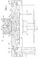
- FIG. 3is a cross-sectional view of the dispersion plate showing separate groups of radially extending gas passages and a center hole through the plate along with the angular relations of the passages to a center axis;
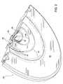
- FIG. 4is an enlarged sectional view partially broken away of the vapor entrance of the dispersion plate of FIGS. 1-3;
- FIG. 5is a graph with a line illustrating the relationship between vapor phase on one side of the line versus solid phase on the other side for a particular material, such as tungsten hexacarbonyl, as a function of temperature and pressure.
- the apparatus 10comprises a processing chamber 12 (of which only a part is shown), a susceptor or platform 14 , a semiconductor wafer (body) 16 positioned on the platform 14 for CVD processing, a manifold 18 , and a dispersion plate 20 embodying features of the invention for controlling and directing the flow of vaporized (gaseous) material into the chamber 12 so that it flows uniformly down toward the wafer 16 .
- the chamber 12is hermetically sealable and can be maintained at sub-atmospheric pressure.
- the wafer 16after being inserted into the chamber 12 , is lowered onto the platform 14 to the position shown by pins 21 (only one of which is shown).
- the pins 21are vertically movable up and down on command on insertion or removal of the wafer 16 .
- the platform 14may be movable vertically as well.
- the platform 14is heated (by means not shown) and in turn heats the wafer 16 to an elevated temperature (e.g., about 400° C.) At such temperature vaporized material flowing into the chamber 12 upon reaching and touching the surface of the wafer 16 will break down into its constituents and a tungsten film is deposited onto a top surface of the wafer 16 . Unwanted residues and gas are exhausted from the chamber 12 via an exit port (not shown).
- the manifold 18supplies vaporized material to the dispersion plate 20 and is attached by bolts 22 to the plate 20 at a cup-shaped entrance 24 in the dispersion plate 20 .
- the manifold 18(well known in the art) may if deemed desirable apply heat and ultrasonic energy to material (indicated by an arrow 26 ) flowing to it from a source (not shown) to ensure that vaporized material flowing into the entrance 24 is entirely vaporized and free of droplets or particles.
- the dispersion plate 20in the specific embodiment illustrated herein, has in accordance with one feature of the invention high-flow-conductance, that is, low pressure drop across the plate of the vapor flowing through it. This enables the plate 20 to function well in CVD processing using materials such as tungsten hexacarbonyl [W(CO) 6 ] where the pressure within the chamber 12 must be maintained at a low value (e.g., about 50 milli-Torr).
- the plate 20is configured to control and direct the flow of a relatively heavy vapor, such as tungsten hexacarbonyl, so that the vapor flows from the plate 20 uniformly onto the wafer 16 .
- the dispersion plate 20is advantageously made from a disc-like solid block of a metal such as aluminum having high heat conductivity and ease of machining.
- the plate 20is attached to an upper wall 25 of the processing chamber 12 by a plurality of bolts 26 , (only two of which are shown) and together with the wall 25 forms a top seal for the chamber 12 .
- the dispersion plate 20has a center axis 28 and has drilled through it a number of radially extending passages 30 and 32 and a center hole 33 . Vaporized material from the manifold 18 flowing into the entrance 24 flows through the plate 20 along the passages 30 , 32 , and hole 33 as indicated by the respective arrows 34 , 36 , and 37 .
- the plate 20has an output face, generally indicated at 40 , which has cut into it an annular groove, near the outer diameter of the plate 20 and indicated by brackets 42 , a smaller diameter annular groove, indicated by brackets 44 , and a flared opening or funnel 46 beneath the center hole 33 .
- the passages 30 in the plate 20extend radially from the center axis 28 like the individual spokes of a wheel.
- the passages 30are each inclined at a uniform downward angle relative to the axis 28 and each has a diameter larger than that of the passages 32 .
- the lattersimilarly extend like the spokes of a wheel and are inclined downward at an angle smaller than the inclined angle of the passages 30 .
- the diameter of the center hole 33is smaller than that of the passages 32 .
- the particular shapes and configurations of the center hole 33 , funnel 46 , the passages 30 and 32 , and of the grooves 42 and 44 in the output face 40 of the dispersion plate 20ensure that a vaporized material, such as tungsten hexacarbonyl, flowing into the chamber 12 will flow evenly down toward the wafer 16 .
- a thin layer of materiale.g., tungsten metal less than a micron thick
- FIG. 2there is shown a perspective view, partially broken away of the dispersion plate 20 of FIG. 1, showing its output face 40 .
- the face 40has the annular grooves 42 and 44 and the funnel 46 .
- the groove 42is somewhat V-shaped and along its bottom intersects the output ends of the multiple passages 30 (only three of which are visible in this view).
- the groove 44is somewhat V-shaped and along its bottom intersects the output ends of the passages 36 (only some of which are visible).
- the funnel 46provides a flared output for the center hole 33 .
- the passages 30 , 32 , and the hole 33originate in the entrance 24 .
- the grooves 42 , 44 , and the funnel 46blend or mix the individual vapor streams from the passages 30 , 32 and the hole 33 into a uniform flow of gas vapor from the plate 20 toward the wafer 16 (see FIG. 1 ).
- the grooves 42 , 44 , and the funnel 46also eliminate much of the flat part of the surface of the face 40 . This, as will be explained in greater detail hereinafter, helps reduce unwanted deposition of solid material on the face 40 instead of on the wafer 16 .
- FIG. 3there is shown a cross-section of the dispersion plate 20 .
- the spoke-like outer passages 30are inclined relative to the center axis 28 by an angle indicated by an arc 52 .
- Each passage 30extends radially from the entrance 24 to the bottom of the groove 42 .
- the spoke-like inner passages 32are inclined relative to the center axis 28 by an angle indicated by an arc 54 , and each passage 32 extends radially from the entrance 24 to the bottom of the groove 44 .
- the hole 33 and its funnel 46are aligned along the axis 28 .
- FIG. 4there is shown an enlarged cross-section view of the dispersion plate 20 showing further details of the entrance 24 , other portions of the plate being broken away.
- the bottom of the entrance 24has a flat center surface 56 , which is pierced by the center hole 33 .
- the bottom of the entrance 24has an outer, annular shoulder indicated at 58 comprising a downward-sloping surface 60 and a vertical cylindrical wall 62 into which are formed the passages 30 (see also FIGS. 1 and 3 ).
- these passages 30extend radially and individually like the spokes of a wheel from the center axis 28 . They extend downward at an angle (indicated by the arc 52 ) into the groove 42 (see also FIG. 2 ).
- the bottom of the entrance 24 in the plate 20has an intermediate annular shoulder indicated at 64 into which are formed the passages 32 .
- the respective passages 32also extend radially individually from the center axis 28 and extend downward at an angle, indicated by the arc 54 , into their respective groove 44 .
- the provision of the shoulders 58 and 64 in the entrance 24facilitates the accurate placement and forming of the multiple passages 30 and 32 through the dispersion plate 20 .
- FIG. 5there is shown a graph 70 illustrating the relationship of vapor phase to solid phase of a material such as tungsten carbonyl as a function of temperature versus pressure.
- the horizontal axis of the graph 70indicates temperature in degrees Centigrade (° C.), and the vertical axis indicates pressure in Torr. The axes are not necessarily linear.
- the graph 70shows a line 72 along which the material is in vapor phase. When the temperature or pressure moves sufficiently to the left or up in the graph 70 away from the line 72 , the material returns to solid (or liquid) state.
- a range of temperaturesindicated in the graph 70 by a bracket 74
- a range of pressuresindicated by a bracket 76 with a nominal operating value of temperature at a point A and of pressure at a point B.
- the temperature range 74may be 80° C. to 100° C. with a nominal operating value at the point A of about 90° C.
- the pressure range 76may be a few milli-Torr with an operating value at the point B of about 50 milli-Torr.
- the plate 20should have high-flow-conductance, meaning that the pressure drop across or through it be low (e.g., a few milli-Torr).
- the plate 20should also maintain the vapor at a desired temperature (e.g., the temperature value at the point A in the graph 70 ) as the vapor passes within and through the plate 20 .
- the plate 20advantageously is made of a metal, such as aluminum, which meets these needs well.
- the front face 40 of the plate 20is positioned at a relatively close distance (e.g., a faction of an inch) from the wafer 16 and its platform 14 .
- the wafer 16is heated by contact with the platform 14 to an elevated temperature (e.g., 390° C). Heat from the wafer 16 is radiated to the plate face 40 , and some of this radiant heat is absorbed by the dispersion plate 20 which raises its temperature.
- the extent to which the temperature of the plate 20 is raiseddepends on, among other things, the surface-reflectivity of the face 40 . The higher the reflectivity, the lower the absorption of radiated heat and hence lower temperature rise for the plate 20 .
- the diameter of the outer passages 30 in the dispersion plate 20is about 0.25 inch; the diameter of the inner passages 32 is about 0.15 inch; and the diameter of the center hole 33 is about 0.060 inch.
- the inside diameter of the entrance 24is about two inches and depth about half an inch.
- the diameter of the dispersion plate 20 between opposite bolts 26is about 9 inches.
- the thickness of the plate 20 from the bottom of the entrance 24 to the front face 40is about an inch.
- the angle 52(FIG.
- the dispersion plate 20is imagined as the face of a clock
- the group of twenty-four passages 30point respectively to each hour and half-hour (e.g., 12, 12:30, 1, 1:30, etc.) around the clock.
- the twelve passages 32point respectively to fifteen minutes after each hour (e.g., 12:15, 1:15, 2:15 etc.) around the clock.
- the passages 30are offset around the center axis 28 by a small angle relative to the passages 32 .
- a flow of vaporized tungsten hexacarbonyl in the range from about 2 to 10 standard cubic centimeters per minute (SCCM) mixed with about 100 SCCM of argonwas passed through the plate 20 (maintained at about 90° C.) into the chamber 12 where the pressure was about 50 milli-Torr.
- the temperature of the wafer 16was about 390° C. and it was positioned about one-half inch from the face 40 of the plate 20 .
- the processing cyclelasted several minutes.
- a dispersion plateit is not limited to a particular set of dimensions or diameter of a dispersion plate, or to the particular numbers, sizes and angles of the passages 30 and 32 , or the center hole 33 , as described above, or to a particular material or method of manufacture for a dispersion plate or to a particular size, shape and number of annular grooves and center funnel in the face of the plate.
Landscapes
- Chemical & Material Sciences (AREA)
- General Chemical & Material Sciences (AREA)
- Chemical Kinetics & Catalysis (AREA)
- Engineering & Computer Science (AREA)
- Materials Engineering (AREA)
- Mechanical Engineering (AREA)
- Metallurgy (AREA)
- Organic Chemistry (AREA)
- Chemical Vapour Deposition (AREA)
Abstract
Description
This invention relates to a dispersion plate for gasses, such as vaporized tungsten hexacarbonyl, flowing through the plate into a reaction chamber to deposit by chemical vapor deposition metal films on a surface of a semiconductor wafer.
The widespread use of semiconductors is due to their usefulness, their cost effectiveness and to their unique capabilities. Accompanying the growth in the use, and usefulness, of semiconductors is the development of new processes and materials for the design and manufacture of semiconductors together with new or improved manufacturing equipment and hardware. An important recent development is the use of copper (which has about twice the unit conductivity of more commonly used aluminum) for electrical interconnections, or circuit traces within very large scale integrated circuits (VLSIs). The use of copper has permitted faster speeds of operation and greater capability of the VLSI circuits but has led to the need to prevent atoms of copper in the copper circuits from adversely interacting with atoms of other materials used in the VLSIs. One way of preventing such interactions is to provide a “barrier” layer over and/or under the copper, such as a thin layer of tungsten (W).
It is known that a layer of a material such as tungsten can be deposited by chemical vapor deposition (CVD) onto exposed surfaces of a semiconductor wafer during processing into VLSIs. Tungsten, which is a relatively heavy metal having an atomic weight of 183.86, has high temperature resistance and provides suitable protection against the reaction of copper with other materials during the fabrication of VLSIs. A compound of tungsten, namely tungsten hexacarbonyl [W(CO)6], can be vaporized under suitable conditions of pressure and temperature to obtain a gaseous phase of the compound which can then be used in CVD processing to form a film or layer of metallic tungsten on a semiconductor wafer. This will be explained in greater detail hereinafter.
It is desirable that a layer of metal (such as tungsten) being deposited by CVD on a semiconductor wafer be uniform in thickness. To achieve this, a chemical vapor compound of the material flowing into a reaction chamber where the semiconductor wafer is being processed should be controlled in flow direction and amplitude so that the vapor is evenly distributed and flows uniformly toward the wafer. This is especially true of a material such as tungsten hexacarbonyl vapor, the molecules of which have relatively high weight and inertia. In addition, because a CVD process step using a compound such as tungsten hexacarbonyl is typically carried out in a reaction chamber maintained under low pressure conditions (e.g., a small fraction of a Torr), the flow of gas vapor into the chamber through a dispersion plate should have high-flow-conductance so that pressure drop across it is relatively low. The gas vapor should also be controlled in temperature as it passes through the plate and enters the chamber to prevent condensation of the vapor.
It is desirable to have a simple and efficient dispersion plate which fills the above described needs.
In accordance with the invention in one specific embodiment thereof, there is provided a dispersion plate for applying vapors of materials useful in chemical vapor deposition in the processing of semiconductors. The dispersion plate comprises a body having a center axis, an outer diameter, an input face, an output face, and a thickness between the faces with an entrance along the center axis in the input face for receiving a stream of vaporized material. The plate defines a plurality of passages through the plate for flow of vapor, each passage having a length and a diameter and extending radially from the center axis at respective inclined angles from the input face to the output face. The plate further defines a hole having a diameter and extending along the center axis from the entrance in the input face to the output face. The hole and plurality of passages have sufficiently large diameters to result in a relatively low pressure drop to the vapor flowing through them and to provide dispersion of vapor flowing through the plate such that vapor flows evenly onto the surface of the semiconductor body.
A better understanding of the invention together with a fuller appreciation of its many advantages will best be gained from a study of the following description given in conjunction with the accompanying drawings and claims.
FIG. 1 is a cross-sectional view of semiconductor processing apparatus, partially broken away, including a high-flow-conductance dispersion plate embodying features of the invention;
FIG. 2 is a perspective view, partially broken away, of the dispersion plate showing in this specific embodiment of the invention, shapes and locations of passages and a center hole through the output face of the plate for the control and direction of gas vapor flow into the processing apparatus;
FIG. 3 is a cross-sectional view of the dispersion plate showing separate groups of radially extending gas passages and a center hole through the plate along with the angular relations of the passages to a center axis;
FIG. 4 is an enlarged sectional view partially broken away of the vapor entrance of the dispersion plate of FIGS. 1-3; and
FIG. 5 is a graph with a line illustrating the relationship between vapor phase on one side of the line versus solid phase on the other side for a particular material, such as tungsten hexacarbonyl, as a function of temperature and pressure.
The drawings are not necessarily to scale.
Referring now to FIG. 1, there is shown in cross-section and partially broken away, anapparatus 10 useful in chemical vapor deposition (CVD) of materials onto semiconductor wafers. Theapparatus 10 comprises a processing chamber12 (of which only a part is shown), a susceptor orplatform 14, a semiconductor wafer (body)16 positioned on theplatform 14 for CVD processing, amanifold 18, and adispersion plate 20 embodying features of the invention for controlling and directing the flow of vaporized (gaseous) material into thechamber 12 so that it flows uniformly down toward thewafer 16. Thechamber 12, is hermetically sealable and can be maintained at sub-atmospheric pressure. Thewafer 16, after being inserted into thechamber 12, is lowered onto theplatform 14 to the position shown by pins21 (only one of which is shown). Thepins 21 are vertically movable up and down on command on insertion or removal of thewafer 16. Theplatform 14 may be movable vertically as well. Theplatform 14 is heated (by means not shown) and in turn heats thewafer 16 to an elevated temperature (e.g., about 400° C.) At such temperature vaporized material flowing into thechamber 12 upon reaching and touching the surface of thewafer 16 will break down into its constituents and a tungsten film is deposited onto a top surface of thewafer 16. Unwanted residues and gas are exhausted from thechamber 12 via an exit port (not shown).
Themanifold 18 supplies vaporized material to thedispersion plate 20 and is attached bybolts 22 to theplate 20 at a cup-shaped entrance 24 in thedispersion plate 20. The manifold18 (well known in the art) may if deemed desirable apply heat and ultrasonic energy to material (indicated by an arrow26) flowing to it from a source (not shown) to ensure that vaporized material flowing into theentrance 24 is entirely vaporized and free of droplets or particles.
Thedispersion plate 20, in the specific embodiment illustrated herein, has in accordance with one feature of the invention high-flow-conductance, that is, low pressure drop across the plate of the vapor flowing through it. This enables theplate 20 to function well in CVD processing using materials such as tungsten hexacarbonyl [W(CO)6] where the pressure within thechamber 12 must be maintained at a low value (e.g., about 50 milli-Torr). In accordance with another feature of the invention, theplate 20 is configured to control and direct the flow of a relatively heavy vapor, such as tungsten hexacarbonyl, so that the vapor flows from theplate 20 uniformly onto thewafer 16. This helps ensure that a film (e.g., of tungsten) being deposited onto thewafer 16 has improved uniformity across thewafer 16. Thedispersion plate 20 is advantageously made from a disc-like solid block of a metal such as aluminum having high heat conductivity and ease of machining. Theplate 20 is attached to anupper wall 25 of theprocessing chamber 12 by a plurality ofbolts 26, (only two of which are shown) and together with thewall 25 forms a top seal for thechamber 12.
As will be explained in greater detail hereinafter, thedispersion plate 20 has acenter axis 28 and has drilled through it a number of radially extendingpassages center hole 33. Vaporized material from themanifold 18 flowing into theentrance 24 flows through theplate 20 along thepassages hole 33 as indicated by therespective arrows plate 20 has an output face, generally indicated at40, which has cut into it an annular groove, near the outer diameter of theplate 20 and indicated bybrackets 42, a smaller diameter annular groove, indicated bybrackets 44, and a flared opening orfunnel 46 beneath thecenter hole 33.
Thepassages 30 in theplate 20 extend radially from thecenter axis 28 like the individual spokes of a wheel. Thepassages 30 are each inclined at a uniform downward angle relative to theaxis 28 and each has a diameter larger than that of thepassages 32. The latter similarly extend like the spokes of a wheel and are inclined downward at an angle smaller than the inclined angle of thepassages 30. The diameter of thecenter hole 33 is smaller than that of thepassages 32. The particular shapes and configurations of thecenter hole 33,funnel 46, thepassages grooves output face 40 of thedispersion plate 20, in the specific embodiment of the invention illustrated herein, ensure that a vaporized material, such as tungsten hexacarbonyl, flowing into thechamber 12 will flow evenly down toward thewafer 16. An important result of this is that a thin layer of material (e.g., tungsten metal less than a micron thick) can be deposited with improved uniformity across the surface of thewafer 16.
Referring now to FIG. 2, there is shown a perspective view, partially broken away of thedispersion plate 20 of FIG. 1, showing itsoutput face 40. As seen in FIG. 2, theface 40 has theannular grooves funnel 46. Thegroove 42 is somewhat V-shaped and along its bottom intersects the output ends of the multiple passages30 (only three of which are visible in this view). Similarly, thegroove 44 is somewhat V-shaped and along its bottom intersects the output ends of the passages36 (only some of which are visible). Thefunnel 46 provides a flared output for thecenter hole 33. Thepassages hole 33 originate in theentrance 24. Thegrooves funnel 46 blend or mix the individual vapor streams from thepassages hole 33 into a uniform flow of gas vapor from theplate 20 toward the wafer16 (see FIG.1). Thegrooves funnel 46 also eliminate much of the flat part of the surface of theface 40. This, as will be explained in greater detail hereinafter, helps reduce unwanted deposition of solid material on theface 40 instead of on thewafer 16.
Referring now to FIG. 3 there is shown a cross-section of thedispersion plate 20. The spoke-likeouter passages 30 are inclined relative to thecenter axis 28 by an angle indicated by anarc 52. Eachpassage 30 extends radially from theentrance 24 to the bottom of thegroove 42. The spoke-likeinner passages 32 are inclined relative to thecenter axis 28 by an angle indicated by anarc 54, and eachpassage 32 extends radially from theentrance 24 to the bottom of thegroove 44. Thehole 33 and itsfunnel 46 are aligned along theaxis 28.
Referring now to FIG. 4, there is shown an enlarged cross-section view of thedispersion plate 20 showing further details of theentrance 24, other portions of the plate being broken away. The bottom of theentrance 24 has aflat center surface 56, which is pierced by thecenter hole 33. The bottom of theentrance 24 has an outer, annular shoulder indicated at58 comprising a downward-slopingsurface 60 and a verticalcylindrical wall 62 into which are formed the passages30 (see also FIGS.1 and3). As was explained previously, thesepassages 30 extend radially and individually like the spokes of a wheel from thecenter axis 28. They extend downward at an angle (indicated by the arc52) into the groove42 (see also FIG.2). Similarly, the bottom of theentrance 24 in theplate 20 has an intermediate annular shoulder indicated at64 into which are formed thepassages 32. Like thepassages 30, therespective passages 32 also extend radially individually from thecenter axis 28 and extend downward at an angle, indicated by thearc 54, into theirrespective groove 44. The provision of theshoulders entrance 24 facilitates the accurate placement and forming of themultiple passages dispersion plate 20.
Referring now to FIG. 5, there is shown agraph 70 illustrating the relationship of vapor phase to solid phase of a material such as tungsten carbonyl as a function of temperature versus pressure. The horizontal axis of thegraph 70 indicates temperature in degrees Centigrade (° C.), and the vertical axis indicates pressure in Torr. The axes are not necessarily linear. Thegraph 70 shows aline 72 along which the material is in vapor phase. When the temperature or pressure moves sufficiently to the left or up in thegraph 70 away from theline 72, the material returns to solid (or liquid) state. For a given material (e.g., tungsten hexacarbonyl), when being used in CVD processing there are conveniently employed a range of temperatures, indicated in thegraph 70 by abracket 74, and a range of pressures indicated by abracket 76 with a nominal operating value of temperature at a point A and of pressure at a point B. In the case of tungsten hexacarbonyl, thetemperature range 74 may be 80° C. to 100° C. with a nominal operating value at the point A of about 90° C. Thepressure range 76 may be a few milli-Torr with an operating value at the point B of about 50 milli-Torr.
It is apparent from thegraph 70, that a material such as tungsten hexacarbonyl, when employed in CVD processing in theapparatus 10 requires a low chamber pressure (e.g., about 50 milli-Torr). Such material at normal atmospheric temperature and pressure is a solid but it can be made to sublime into vapor. It is delivered, as indicated by thearrow 26, to the manifold18 (FIG. 1) It is desirable therefore to prevent the vapor from returning to solid (or liquid) phase in passing from the manifold18 into and through thedispersion plate 20 that such vapor not be significantly impeded in its flow. Accordingly, theplate 20 should have high-flow-conductance, meaning that the pressure drop across or through it be low (e.g., a few milli-Torr). Theplate 20 should also maintain the vapor at a desired temperature (e.g., the temperature value at the point A in the graph70) as the vapor passes within and through theplate 20. Theplate 20 advantageously is made of a metal, such as aluminum, which meets these needs well.
As is shown in FIG. 1, thefront face 40 of theplate 20 is positioned at a relatively close distance (e.g., a faction of an inch) from thewafer 16 and itsplatform 14. During operation of theapparatus 10 thewafer 16 is heated by contact with theplatform 14 to an elevated temperature (e.g., 390° C). Heat from thewafer 16 is radiated to theplate face 40, and some of this radiant heat is absorbed by thedispersion plate 20 which raises its temperature. The extent to which the temperature of theplate 20 is raised depends on, among other things, the surface-reflectivity of theface 40. The higher the reflectivity, the lower the absorption of radiated heat and hence lower temperature rise for theplate 20. Where deposition of solid material, such as a thin layer of a tungsten compound, occurs on theface 40 its reflectivity increases substantially. But the presence of thegrooves funnel 46 cut into theface 40 of theplate 20 minimizes the deposition of solid material on theface 40. Thus it is possible during CVD processing with a vaporized material such as tungsten hexacarbonyl, to operate theapparatus 10 with theplate 20 at a desired temperature (e.g., 90° C.) maintained at a substantially constant value by radiant heat alone and not affected by changes in surface reflectivity. There is no need under these conditions for an additional heat source for theplate 20. Also, because thepassages center hole 33 through theplate 20 are relatively large, plasma-excited gas can pass through theplate 20. This makes it possible to place a source for plasma excitation above theentrance 24 in theplate 20 and outside of thechamber 12.
In the specific embodiment of the invention illustrated herein, the diameter of theouter passages 30 in thedispersion plate 20 is about 0.25 inch; the diameter of theinner passages 32 is about 0.15 inch; and the diameter of thecenter hole 33 is about 0.060 inch. There are twenty-fourouter passages 30, twelveinner passages 32 and onecenter hole 33 for a total of thirty-seven openings for vapor flow through theplate 20 downward and outward from theentrance 24. The inside diameter of theentrance 24 is about two inches and depth about half an inch. The diameter of thedispersion plate 20 betweenopposite bolts 26 is about 9 inches. The thickness of theplate 20 from the bottom of theentrance 24 to thefront face 40 is about an inch. The angle52 (FIG. 3) is about 70° and theangle 54, about 50°. If thedispersion plate 20 is imagined as the face of a clock, the group of twenty-fourpassages 30 point respectively to each hour and half-hour (e.g., 12, 12:30, 1, 1:30, etc.) around the clock. The twelvepassages 32 point respectively to fifteen minutes after each hour (e.g., 12:15, 1:15, 2:15 etc.) around the clock. Thus, thepassages 30 are offset around thecenter axis 28 by a small angle relative to thepassages 32. During CVD processing a flow of vaporized tungsten hexacarbonyl in the range from about 2 to 10 standard cubic centimeters per minute (SCCM) mixed with about 100 SCCM of argon was passed through the plate20 (maintained at about 90° C.) into thechamber 12 where the pressure was about 50 milli-Torr. The temperature of thewafer 16 was about 390° C. and it was positioned about one-half inch from theface 40 of theplate 20. The processing cycle lasted several minutes.
The above description is intended in illustration and not in limitation of the invention. Various changes or modifications in thedispersion plate 20 embodying features of the invention may occur to those skilled in the art and can be made without departing from the spirit or scope of the invention as set forth herein and as defined by the accompanying claims. For example, the invention is not limited to use with only vaporized tungsten hexacarbonyl but is useful with other vaporized materials. Still further, it is not limited to a particular set of dimensions or diameter of a dispersion plate, or to the particular numbers, sizes and angles of thepassages center hole 33, as described above, or to a particular material or method of manufacture for a dispersion plate or to a particular size, shape and number of annular grooves and center funnel in the face of the plate.
Claims (16)
1. A dispersion plate for applying vapors of materials useful in chemical vapor deposition of layers onto a surface of a semiconductor body, the dispersion plate comprising:
a body having a center axis, an outer diameter, an input face, an output face, and a thickness between the faces;
an entrance along the center axis in the input face for receiving a stream of vaporized material;
the plate defining a plurality of passages therethrough, each passage having a length and a diameter and extending radially from the center axis at respective inclined angles from the input face to the output face; and
the plate defining a hole therethrough having a diameter and extending along the center axis from the entrance in the input face to the output face, the hole and plurality of passages having sufficiently large diameters to result in a relatively low pressure drop to vapor flowing through them and to provide dispersion of vapor flowing through the plate such that vapor flows evenly onto the surface of the semiconductor body.
2. The dispersion plate of claim1 wherein there are a first plurality and a second plurality of passages, the first plurality of passages having respective lengths and diameters greater than the lengths and diameters of the second plurality of passages and lying at respective inclined angles different from the inclined angles of the second plurality of passages.
3. The dispersion plate of claim2 wherein there are twenty-four passages in the first plurality, and twelve in the second plurality of passages, the diameter of each of the first passages being about 0.25 inch, the diameter of each of the second passages being about 0.15 inch, and the diameter of the hole being about 0.060 inch, such that the plate has high-flow-conductance, and plasma-excited gas can pass through the plate.
4. The dispersion plate of claim1 wherein the plate is a disc-like block of a metal such as aluminum having high heat conductivity such that vaporized material flowing through the plate can be maintained at a desired temperature to minimize the formation of droplets or particles of the material.
5. The dispersion plate of claim1 wherein the output face of the plate has formed therein at least one annular groove, the bottom of which intersects respective ones of the passages, the output face having a funnel formed into it and extending to the hole along the center axis, such that gas vapor flowing from the passages and hole is blended into a uniform flow, and unwanted deposition of solid material onto the front face is minimized.
6. A dispersion plate for evenly flowing into a processing chamber a vaporized material such as a tungsten compound during chemical vapor deposition of metal layers onto a semiconductor body, the plate comprising:
a disc-like body having a center axis, an outer diameter, an input face, an output face, and a thickness between the faces;
the disc-like body defining a cup-like entrance along the center axis in the input face for receiving a stream of vaporized material;
the disc-like body defining a first plurality of passages for flow of vapor, each passage having a length and a diameter and extending radially from the entrance like the spokes of a wheel at a first inclined angle relative to the center axis from the input face to the output face;
the disc-like body defining a second plurality of passages for flow of vapor, each passage having a length and a diameter and extending radially from the entrance like the spokes of a wheel at a second inclined angle relative to the center axis from the input face to the output face;
the disc-like body defining a hole therethrough having a flared diameter and extending along the center axis from the entrance in the input face to the output face, the hole and plurality of passages having sufficiently large diameters to cause only low pressure drop to flow of vapor flowing through them; and
a first and a second annular groove formed into the output face, the bottom of the first groove intersecting with the first plurality of passages, the bottom of the second groove intersecting with the second plurality of passages, such that streams of vapor flowing through the passages are blended to achieve a relatively even flow of vapor onto the semiconductor body and deposition of solid material on the output face is minimized.
7. The dispersion plate of claim6 wherein the cup-like entrance has a bottom and a side wall, there being an outer, sloping shoulder and an inner sloping shoulder cut into the bottom at respective angles which facilitate drilling through the plate the first and second passages.
8. The dispersion plate of claim7 wherein the body is made from a solid block of aluminum such that vapor flowing through the plate can be kept at a desired temperature by the plate.
9. The dispersion plate of claim6 wherein the first plurality of passages is offset around the center axis by a small angle relative to the second plurality of passages.
10. The dispersion plate of claim6 wherein the diameter of each of the first plurality of passages is about 0.25 inch, the diameter of each of the second plurality of passages is about 0.15 inch, and the plate is about an inch thick and about 9 inches in diameter.
11. Apparatus for processing of semiconductor wafers, the apparatus comprising:
a processing chamber which can be maintained at sub-atmospheric pressure;
a platform or susceptor within the chamber for holding a wafer during processing; and
a dispersion plate for flowing into the chamber and onto a wafer vaporized material for chemical vapor deposition of a solid film onto the wafer, the plate comprising:
a disc-like body having a center axis, an outer diameter, an input face, and output face, and a thickness between the faces;
an entrance along the center axis in the input face for receiving a stream of vaporized material;
the body defining a plurality of passages through the plate for flow of vaporized material, each passage having a length and a diameter and extending radially like spokes of a wheel from the center axis at respective inclined angles from the input face to the output face; and
the body defining a hole therethrough having a diameter and extending along the center axis from the entrance in the input face to the output face, the hole and plurality of passages having sufficiently large diameters to give minimal pressure drop to the vaporized material flowing through them and to provide dispersion of flow through the plate such that vaporized material flows evenly onto a wafer surface.
12. The apparatus of claim11 wherein the wafer is heated to about 400° C., the vaporized material is a metal compound such as tungsten hexacarbonyl, the dispersion plate has high thermal conductivity and is held at about 90° C., and the pressure within the chamber is about 50 milli-Torr.
13. The apparatus of claim12 wherein the dispersion plate is held at about 90° C. by heat radiated from the wafer and susceptor.
14. Apparatus for chemical vapor deposition (CVD) of metal films onto semiconductor wafers, the apparatus comprising:
a processing chamber which can be maintained at pressures of less than a Torr;
a platform within the chamber for holding and heating a wafer during processing; and
a dispersion plate for flowing into the chamber and onto a wafer vaporized metal compound for chemical vapor deposition of a metal film onto a wafer;
the plate comprising:
a disc-like body having a center axis, an outer diameter, an input face, and output face, and a thickness between the faces;
an entrance along the center axis in the input face for receiving a stream of the vaporized material from an external source;
the body defining a first plurality of passages for flow of vapor, each passage having a length and a diameter and extending radially from the entrance like the spokes of a wheel at a first inclined angle relative to the center axis from the input face to the output face;
the body defining a second plurality of passages for flow of vapor, each passage having a length and a diameter and extending radially from the entrance like the spokes of a wheel at a second inclined angle relative to the center axis from the input face to the output face;
the body defining therethrough a hole having a flared diameter and extending along the center axis from the entrance in the input face to the output face, the hole and plurality of passages having sufficiently large diameters to cause only minimal pressure drop to flow of vapor flowing through them; and
a first and a second annular groove formed into the output face, the bottom of the first groove intersecting with the first plurality of passages, the bottom of the second groove intersecting with the second plurality of passages, such that streams of vapor flowing through the passages are blended to achieve more even flow of vapor onto a semiconductor wafer and deposition of solid material on the output face is minimized.
15. The apparatus of claim14 wherein there are several dozen passages in the first plurality and about a dozen in the second plurality of passages, the diameter of each of the passages in the second plurality being smaller than that of each of the passages in the first plurality and larger than that of the hole, such that the flow of vaporized material is balanced and even.
16. The apparatus of claim14 wherein the cup-like entrance has a bottom with an outer angular shoulder and an intermediate angular shoulder, the shoulders providing respective entrances for the first and second plurality of passages.
Priority Applications (2)
| Application Number | Priority Date | Filing Date | Title |
|---|---|---|---|
| US09/638,506US6302965B1 (en) | 2000-08-15 | 2000-08-15 | Dispersion plate for flowing vaporizes compounds used in chemical vapor deposition of films onto semiconductor surfaces |
| PCT/US2001/025433WO2002015239A2 (en) | 2000-08-15 | 2001-08-13 | Dispersion plate for flowing vaporized compounds used in chemical vapor deposition of films onto semiconductor surfaces |
Applications Claiming Priority (1)
| Application Number | Priority Date | Filing Date | Title |
|---|---|---|---|
| US09/638,506US6302965B1 (en) | 2000-08-15 | 2000-08-15 | Dispersion plate for flowing vaporizes compounds used in chemical vapor deposition of films onto semiconductor surfaces |
Publications (1)
| Publication Number | Publication Date |
|---|---|
| US6302965B1true US6302965B1 (en) | 2001-10-16 |
Family
ID=24560323
Family Applications (1)
| Application Number | Title | Priority Date | Filing Date |
|---|---|---|---|
| US09/638,506Expired - Fee RelatedUS6302965B1 (en) | 2000-08-15 | 2000-08-15 | Dispersion plate for flowing vaporizes compounds used in chemical vapor deposition of films onto semiconductor surfaces |
Country Status (2)
| Country | Link |
|---|---|
| US (1) | US6302965B1 (en) |
| WO (1) | WO2002015239A2 (en) |
Cited By (119)
| Publication number | Priority date | Publication date | Assignee | Title |
|---|---|---|---|---|
| US20030019428A1 (en)* | 2001-04-28 | 2003-01-30 | Applied Materials, Inc. | Chemical vapor deposition chamber |
| US20030023338A1 (en)* | 2001-07-27 | 2003-01-30 | Applied Materials, Inc. | Atomic layer deposition apparatus |
| US20030140857A1 (en)* | 2002-01-28 | 2003-07-31 | Applied Materials, Inc. | Apparatus and method for low pressure CVD deposition of tungsten and tungsten nitride |
| US20040060514A1 (en)* | 2002-01-25 | 2004-04-01 | Applied Materials, Inc. A Delaware Corporation | Gas distribution showerhead |
| US20040173150A1 (en)* | 2003-03-03 | 2004-09-09 | Derderian Garo J. | Reactors, systems with reaction chambers, and methods for depositing materials onto micro-device workpieces |
| US6793733B2 (en)* | 2002-01-25 | 2004-09-21 | Applied Materials Inc. | Gas distribution showerhead |
| US6916398B2 (en) | 2001-10-26 | 2005-07-12 | Applied Materials, Inc. | Gas delivery apparatus and method for atomic layer deposition |
| US20050271812A1 (en)* | 2004-05-12 | 2005-12-08 | Myo Nyi O | Apparatuses and methods for atomic layer deposition of hafnium-containing high-k dielectric materials |
| US20060086319A1 (en)* | 2003-06-10 | 2006-04-27 | Tokyo Electron Limited | Processing gas supply mechanism, film forming apparatus and method, and computer storage medium storing program for controlling same |
| US7049226B2 (en) | 2001-09-26 | 2006-05-23 | Applied Materials, Inc. | Integration of ALD tantalum nitride for copper metallization |
| US20060115590A1 (en)* | 2004-11-29 | 2006-06-01 | Tokyo Electron Limited; International Business Machines Corporation | Method and system for performing in-situ cleaning of a deposition system |
| US7056806B2 (en) | 2003-09-17 | 2006-06-06 | Micron Technology, Inc. | Microfeature workpiece processing apparatus and methods for controlling deposition of materials on microfeature workpieces |
| US20060130756A1 (en)* | 2004-12-17 | 2006-06-22 | Applied Materials, Inc., A Delaware Corporation | Self-cooling gas delivery apparatus under high vacuum for high density plasma applications |
| US20060196603A1 (en)* | 2005-03-07 | 2006-09-07 | Applied Materials, Inc. | Gas baffle and distributor for semiconductor processing chamber |
| US20060219361A1 (en)* | 2005-04-01 | 2006-10-05 | Lam Research Corporation | High strip rate downstream chamber |
| US20060240542A1 (en)* | 2003-03-12 | 2006-10-26 | Schieve Eric W | Substrate support lift mechanism |
| US20060266289A1 (en)* | 2005-01-18 | 2006-11-30 | Mohith Verghese | Reaction system for growing a thin film |
| US7204886B2 (en) | 2002-11-14 | 2007-04-17 | Applied Materials, Inc. | Apparatus and method for hybrid chemical processing |
| US7235138B2 (en) | 2003-08-21 | 2007-06-26 | Micron Technology, Inc. | Microfeature workpiece processing apparatus and methods for batch deposition of materials on microfeature workpieces |
| US20070151516A1 (en)* | 2006-01-03 | 2007-07-05 | Law Kam S | Chemical vapor deposition apparatus and electrode plate thereof |
| US7258892B2 (en) | 2003-12-10 | 2007-08-21 | Micron Technology, Inc. | Methods and systems for controlling temperature during microfeature workpiece processing, e.g., CVD deposition |
| US20070218200A1 (en)* | 2006-03-16 | 2007-09-20 | Kenji Suzuki | Method and apparatus for reducing particle formation in a vapor distribution system |
| US20070215048A1 (en)* | 2006-03-16 | 2007-09-20 | Kenji Suzuki | Method and apparatus for reducing particle contamination in a deposition system |
| US7282239B2 (en) | 2003-09-18 | 2007-10-16 | Micron Technology, Inc. | Systems and methods for depositing material onto microfeature workpieces in reaction chambers |
| US7294208B2 (en) | 2002-07-29 | 2007-11-13 | Applied Materials, Inc. | Apparatus for providing gas to a processing chamber |
| US7323231B2 (en) | 2003-10-09 | 2008-01-29 | Micron Technology, Inc. | Apparatus and methods for plasma vapor deposition processes |
| US7335396B2 (en) | 2003-04-24 | 2008-02-26 | Micron Technology, Inc. | Methods for controlling mass flow rates and pressures in passageways coupled to reaction chambers and systems for depositing material onto microfeature workpieces in reaction chambers |
| US7342984B1 (en) | 2003-04-03 | 2008-03-11 | Zilog, Inc. | Counting clock cycles over the duration of a first character and using a remainder value to determine when to sample a bit of a second character |
| US7344755B2 (en) | 2003-08-21 | 2008-03-18 | Micron Technology, Inc. | Methods and apparatus for processing microfeature workpieces; methods for conditioning ALD reaction chambers |
| US7352048B2 (en) | 2001-09-26 | 2008-04-01 | Applied Materials, Inc. | Integration of barrier layer and seed layer |
| US20080092820A1 (en)* | 2006-10-23 | 2008-04-24 | Yas Co., Ltd. | Evaporator having multi-layered conical slit nozzles for vacuum thermal evaporation |
| US20080099147A1 (en)* | 2006-10-26 | 2008-05-01 | Nyi Oo Myo | Temperature controlled multi-gas distribution assembly |
| US20080121179A1 (en)* | 2006-11-28 | 2008-05-29 | Applied Materials, Inc. | Gas baffle and distributor for semiconductor processing chamber |
| US20080121178A1 (en)* | 2006-11-28 | 2008-05-29 | Applied Materials, Inc. | Dual top gas feed through distributor for high density plasma chamber |
| US7387685B2 (en) | 2002-07-08 | 2008-06-17 | Micron Technology, Inc. | Apparatus and method for depositing materials onto microelectronic workpieces |
| US7402534B2 (en) | 2005-08-26 | 2008-07-22 | Applied Materials, Inc. | Pretreatment processes within a batch ALD reactor |
| US7413611B2 (en)* | 2003-07-25 | 2008-08-19 | Tokyo Electron Limited | Gas reaction system and semiconductor processing apparatus |
| US7416979B2 (en) | 2001-07-25 | 2008-08-26 | Applied Materials, Inc. | Deposition methods for barrier and tungsten materials |
| US7422637B2 (en) | 2002-10-09 | 2008-09-09 | Applied Materials, Inc. | Processing chamber configured for uniform gas flow |
| US7422635B2 (en) | 2003-08-28 | 2008-09-09 | Micron Technology, Inc. | Methods and apparatus for processing microfeature workpieces, e.g., for depositing materials on microfeature workpieces |
| US7429361B2 (en) | 2002-07-17 | 2008-09-30 | Applied Materials, Inc. | Method and apparatus for providing precursor gas to a processing chamber |
| US7431967B2 (en) | 2002-09-19 | 2008-10-07 | Applied Materials, Inc. | Limited thermal budget formation of PMD layers |
| US7456116B2 (en) | 2002-09-19 | 2008-11-25 | Applied Materials, Inc. | Gap-fill depositions in the formation of silicon containing dielectric materials |
| US7464917B2 (en) | 2005-10-07 | 2008-12-16 | Appiled Materials, Inc. | Ampoule splash guard apparatus |
| US7481887B2 (en) | 2002-05-24 | 2009-01-27 | Micron Technology, Inc. | Apparatus for controlling gas pulsing in processes for depositing materials onto micro-device workpieces |
| US20090042407A1 (en)* | 2006-11-28 | 2009-02-12 | Applied Materials, Inc. | Dual Top Gas Feed Through Distributor for High Density Plasma Chamber |
| US20090056626A1 (en)* | 2002-01-25 | 2009-03-05 | Applied Materials, Inc. | Apparatus for cyclical depositing of thin films |
| US20090068084A1 (en)* | 2007-09-06 | 2009-03-12 | Jong-Kwan Jeon | Apparatus and method for producing carbon nanotubes |
| US7514358B2 (en) | 2002-03-04 | 2009-04-07 | Applied Materials, Inc. | Sequential deposition of tantalum nitride using a tantalum-containing precursor and a nitrogen-containing precursor |
| US20090093129A1 (en)* | 2006-11-28 | 2009-04-09 | Applied Materials, Inc. | Gas Baffle and Distributor for Semiconductor Processing Chamber |
| US20090136665A1 (en)* | 2007-11-27 | 2009-05-28 | Asm Genitech Korea Ltd. | Atomic layer deposition apparatus |
| US20090133837A1 (en)* | 2004-02-25 | 2009-05-28 | Advanced Display Process Engineering Co., Ltd. | Apparatus for manufacturing flat-panel display |
| US20090133622A1 (en)* | 2007-11-23 | 2009-05-28 | Industrial Technology Research Institute | Plasma assisted apparatus for organic film deposition |
| US7547952B2 (en) | 2003-04-04 | 2009-06-16 | Applied Materials, Inc. | Method for hafnium nitride deposition |
| US20090159424A1 (en)* | 2007-12-19 | 2009-06-25 | Wei Liu | Dual zone gas injection nozzle |
| US7581511B2 (en) | 2003-10-10 | 2009-09-01 | Micron Technology, Inc. | Apparatus and methods for manufacturing microfeatures on workpieces using plasma vapor processes |
| US7584942B2 (en) | 2004-03-31 | 2009-09-08 | Micron Technology, Inc. | Ampoules for producing a reaction gas and systems for depositing materials onto microfeature workpieces in reaction chambers |
| US7588804B2 (en) | 2002-08-15 | 2009-09-15 | Micron Technology, Inc. | Reactors with isolated gas connectors and methods for depositing materials onto micro-device workpieces |
| US7601648B2 (en) | 2006-07-31 | 2009-10-13 | Applied Materials, Inc. | Method for fabricating an integrated gate dielectric layer for field effect transistors |
| US7611990B2 (en) | 2001-07-25 | 2009-11-03 | Applied Materials, Inc. | Deposition methods for barrier and tungsten materials |
| US7642171B2 (en) | 2004-08-04 | 2010-01-05 | Applied Materials, Inc. | Multi-step anneal of thin films for film densification and improved gap-fill |
| US7647886B2 (en) | 2003-10-15 | 2010-01-19 | Micron Technology, Inc. | Systems for depositing material onto workpieces in reaction chambers and methods for removing byproducts from reaction chambers |
| US7674727B2 (en) | 2002-09-19 | 2010-03-09 | Applied Materials, Inc. | Nitrous oxide anneal of TEOS/ozone CVD for improved gapfill |
| US7682946B2 (en) | 2005-11-04 | 2010-03-23 | Applied Materials, Inc. | Apparatus and process for plasma-enhanced atomic layer deposition |
| US7699023B2 (en)* | 2001-10-26 | 2010-04-20 | Applied Materials, Inc. | Gas delivery apparatus for atomic layer deposition |
| US7699932B2 (en) | 2004-06-02 | 2010-04-20 | Micron Technology, Inc. | Reactors, systems and methods for depositing thin films onto microfeature workpieces |
| US20100101491A1 (en)* | 2008-10-29 | 2010-04-29 | Asm Japan K.K. | Wafer lift pins suspended and supported at underside of susceptor |
| US7798096B2 (en) | 2006-05-05 | 2010-09-21 | Applied Materials, Inc. | Plasma, UV and ion/neutral assisted ALD or CVD in a batch tool |
| US7906393B2 (en) | 2004-01-28 | 2011-03-15 | Micron Technology, Inc. | Methods for forming small-scale capacitor structures |
| US7905959B2 (en) | 2001-07-16 | 2011-03-15 | Applied Materials, Inc. | Lid assembly for a processing system to facilitate sequential deposition techniques |
| US20110098841A1 (en)* | 2008-03-27 | 2011-04-28 | Tokyo Electron Limited | Gas supply device, processing apparatus, processing method, and storage medium |
| US8110489B2 (en) | 2001-07-25 | 2012-02-07 | Applied Materials, Inc. | Process for forming cobalt-containing materials |
| US8119210B2 (en) | 2004-05-21 | 2012-02-21 | Applied Materials, Inc. | Formation of a silicon oxynitride layer on a high-k dielectric material |
| US8133554B2 (en) | 2004-05-06 | 2012-03-13 | Micron Technology, Inc. | Methods for depositing material onto microfeature workpieces in reaction chambers and systems for depositing materials onto microfeature workpieces |
| US8146896B2 (en) | 2008-10-31 | 2012-04-03 | Applied Materials, Inc. | Chemical precursor ampoule for vapor deposition processes |
| US20120111271A1 (en)* | 2007-10-11 | 2012-05-10 | Begarney Michael J | Chemical vapor deposition reactor |
| US8187970B2 (en) | 2001-07-25 | 2012-05-29 | Applied Materials, Inc. | Process for forming cobalt and cobalt silicide materials in tungsten contact applications |
| US8323754B2 (en) | 2004-05-21 | 2012-12-04 | Applied Materials, Inc. | Stabilization of high-k dielectric materials |
| US20130126486A1 (en)* | 2011-11-22 | 2013-05-23 | Ryan Bise | Multi Zone Gas Injection Upper Electrode System |
| US20140217193A1 (en)* | 2013-02-06 | 2014-08-07 | Novellus Systems, Inc. | Method and apparatus for purging and plasma suppression in a process chamber |
| US8821637B2 (en) | 2007-01-29 | 2014-09-02 | Applied Materials, Inc. | Temperature controlled lid assembly for tungsten nitride deposition |
| US9018108B2 (en) | 2013-01-25 | 2015-04-28 | Applied Materials, Inc. | Low shrinkage dielectric films |
| CN104681386A (en)* | 2013-11-29 | 2015-06-03 | 株式会社日立国际电气 | Substrate processing apparatus, substrate processing method and method of manufacturing semiconductor device |
| US20150152991A1 (en)* | 2013-11-29 | 2015-06-04 | Taiwan Semiconductor Manufacturing Co., Ltd. | Mechanisms for supplying process gas into wafer process apparatus |
| US9051641B2 (en) | 2001-07-25 | 2015-06-09 | Applied Materials, Inc. | Cobalt deposition on barrier surfaces |
| US9083182B2 (en) | 2011-11-21 | 2015-07-14 | Lam Research Corporation | Bypass capacitors for high voltage bias power in the mid frequency RF range |
| US9287152B2 (en) | 2009-12-10 | 2016-03-15 | Orbotech LT Solar, LLC. | Auto-sequencing multi-directional inline processing method |
| US9388492B2 (en) | 2011-12-27 | 2016-07-12 | Asm America, Inc. | Vapor flow control apparatus for atomic layer deposition |
| US9396908B2 (en) | 2011-11-22 | 2016-07-19 | Lam Research Corporation | Systems and methods for controlling a plasma edge region |
| US9462921B2 (en) | 2011-05-24 | 2016-10-11 | Orbotech LT Solar, LLC. | Broken wafer recovery system |
| US9508530B2 (en) | 2011-11-21 | 2016-11-29 | Lam Research Corporation | Plasma processing chamber with flexible symmetric RF return strap |
| US9574268B1 (en)* | 2011-10-28 | 2017-02-21 | Asm America, Inc. | Pulsed valve manifold for atomic layer deposition |
| US9758868B1 (en) | 2016-03-10 | 2017-09-12 | Lam Research Corporation | Plasma suppression behind a showerhead through the use of increased pressure |
| US9790596B1 (en)* | 2013-01-30 | 2017-10-17 | Kyocera Corporation | Gas nozzle and plasma device employing same |
| US20180258531A1 (en)* | 2017-03-09 | 2018-09-13 | Applied Materials, Inc. | Diffuser design for flowable cvd |
| US10287683B2 (en) | 2012-06-25 | 2019-05-14 | Lam Research Corporation | Suppression of parasitic deposition in a substrate processing system by suppressing precursor flow and plasma outside of substrate region |
| US10395900B2 (en)* | 2016-06-17 | 2019-08-27 | Samsung Electronics Co., Ltd. | Plasma processing apparatus |
| US10403474B2 (en)* | 2016-07-11 | 2019-09-03 | Lam Research Corporation | Collar, conical showerheads and/or top plates for reducing recirculation in a substrate processing system |
| WO2020013972A1 (en)* | 2018-07-11 | 2020-01-16 | Applied Materials, Inc. | Gas flow guide design for uniform flow distribution and efficient purge |
| US10586686B2 (en) | 2011-11-22 | 2020-03-10 | Law Research Corporation | Peripheral RF feed and symmetric RF return for symmetric RF delivery |
| US10651016B2 (en)* | 2017-03-15 | 2020-05-12 | Hermes-Epitek Corporation | Detachable gas injector used for semiconductor equipment |
| US10662527B2 (en) | 2016-06-01 | 2020-05-26 | Asm Ip Holding B.V. | Manifolds for uniform vapor deposition |
| US10872803B2 (en) | 2017-11-03 | 2020-12-22 | Asm Ip Holding B.V. | Apparatus and methods for isolating a reaction chamber from a loading chamber resulting in reduced contamination |
| US10872804B2 (en) | 2017-11-03 | 2020-12-22 | Asm Ip Holding B.V. | Apparatus and methods for isolating a reaction chamber from a loading chamber resulting in reduced contamination |
| CN112259474A (en)* | 2020-10-19 | 2021-01-22 | 上海华力集成电路制造有限公司 | Plasma source assembly for integrated circuit processing equipment |
| US11053590B2 (en)* | 2014-08-15 | 2021-07-06 | Applied Materials, Inc. | Nozzle for uniform plasma processing |
| CN113622022A (en)* | 2021-09-02 | 2021-11-09 | 河南微米光学科技有限公司 | In-cavity airflow field adjusting device for MPCVD equipment and using method |
| US11342164B2 (en)* | 2011-12-16 | 2022-05-24 | Taiwan Semiconductor Manufacturing Company, Ltd. | High density plasma chemical vapor deposition chamber and method of using |
| CN114641592A (en)* | 2019-08-28 | 2022-06-17 | 朗姆研究公司 | Metal deposition |
| US11384432B2 (en)* | 2015-04-22 | 2022-07-12 | Applied Materials, Inc. | Atomic layer deposition chamber with funnel-shaped gas dispersion channel and gas distribution plate |
| US20220282377A1 (en)* | 2019-08-23 | 2022-09-08 | Lam Research Corporation | Thermally controlled chandelier showerhead |
| US11492701B2 (en) | 2019-03-19 | 2022-11-08 | Asm Ip Holding B.V. | Reactor manifolds |
| US11578408B2 (en)* | 2017-07-24 | 2023-02-14 | Tokyo Electron Limited | Gas processing apparatus |
| US11594400B2 (en)* | 2011-11-23 | 2023-02-28 | Lam Research Corporation | Multi zone gas injection upper electrode system |
| US20230123089A1 (en)* | 2019-06-07 | 2023-04-20 | Applied Materials, Inc. | Faceplate having a curved surface |
| US11767592B2 (en)* | 2019-12-04 | 2023-09-26 | Piotech Inc. | Gas-dispersing apparatus for multiple chemical resources |
| US11830731B2 (en) | 2019-10-22 | 2023-11-28 | Asm Ip Holding B.V. | Semiconductor deposition reactor manifolds |
| US20240240313A1 (en)* | 2022-09-30 | 2024-07-18 | Chuyun Tek (Shanghai) Co., Ltd. | Gas conveying assembly and gas-phase reaction device |
| US12087573B2 (en) | 2019-07-17 | 2024-09-10 | Lam Research Corporation | Modulation of oxidation profile for substrate processing |
Citations (4)
| Publication number | Priority date | Publication date | Assignee | Title |
|---|---|---|---|---|
| US5284519A (en)* | 1990-05-16 | 1994-02-08 | Simon Fraser University | Inverted diffuser stagnation point flow reactor for vapor deposition of thin films |
| US6036783A (en)* | 1996-04-05 | 2000-03-14 | Ebara Corporation | Liquid material vaporizer apparatus and gas ejection device |
| US6179920B1 (en)* | 1998-04-07 | 2001-01-30 | Mitsubishi Denki Kabushiki Kaisha | CVD apparatus for forming thin film having high dielectric constant |
| US6210485B1 (en)* | 1998-07-21 | 2001-04-03 | Applied Materials, Inc. | Chemical vapor deposition vaporizer |
Family Cites Families (3)
| Publication number | Priority date | Publication date | Assignee | Title |
|---|---|---|---|---|
| CH643469A5 (en)* | 1981-12-22 | 1984-06-15 | Siv Soc Italiana Vetro | Installation for continuous drop on the surface of a substrate door high temperature, layer solid matter. |
| FR2718155B1 (en)* | 1994-04-05 | 1996-04-26 | Europ Composants Electron | Method for depositing a dielectric and / or metal on a substrate. |
| JPH113799A (en)* | 1997-06-11 | 1999-01-06 | Hitachi Ltd | Plasma processing equipment |
- 2000
- 2000-08-15USUS09/638,506patent/US6302965B1/ennot_activeExpired - Fee Related
- 2001
- 2001-08-13WOPCT/US2001/025433patent/WO2002015239A2/enactiveApplication Filing
Patent Citations (4)
| Publication number | Priority date | Publication date | Assignee | Title |
|---|---|---|---|---|
| US5284519A (en)* | 1990-05-16 | 1994-02-08 | Simon Fraser University | Inverted diffuser stagnation point flow reactor for vapor deposition of thin films |
| US6036783A (en)* | 1996-04-05 | 2000-03-14 | Ebara Corporation | Liquid material vaporizer apparatus and gas ejection device |
| US6179920B1 (en)* | 1998-04-07 | 2001-01-30 | Mitsubishi Denki Kabushiki Kaisha | CVD apparatus for forming thin film having high dielectric constant |
| US6210485B1 (en)* | 1998-07-21 | 2001-04-03 | Applied Materials, Inc. | Chemical vapor deposition vaporizer |
Cited By (206)
| Publication number | Priority date | Publication date | Assignee | Title |
|---|---|---|---|---|
| US9587310B2 (en) | 2001-03-02 | 2017-03-07 | Applied Materials, Inc. | Lid assembly for a processing system to facilitate sequential deposition techniques |
| US20030019428A1 (en)* | 2001-04-28 | 2003-01-30 | Applied Materials, Inc. | Chemical vapor deposition chamber |
| US7905959B2 (en) | 2001-07-16 | 2011-03-15 | Applied Materials, Inc. | Lid assembly for a processing system to facilitate sequential deposition techniques |
| US10280509B2 (en) | 2001-07-16 | 2019-05-07 | Applied Materials, Inc. | Lid assembly for a processing system to facilitate sequential deposition techniques |
| US7611990B2 (en) | 2001-07-25 | 2009-11-03 | Applied Materials, Inc. | Deposition methods for barrier and tungsten materials |
| US8110489B2 (en) | 2001-07-25 | 2012-02-07 | Applied Materials, Inc. | Process for forming cobalt-containing materials |
| US9209074B2 (en) | 2001-07-25 | 2015-12-08 | Applied Materials, Inc. | Cobalt deposition on barrier surfaces |
| US9051641B2 (en) | 2001-07-25 | 2015-06-09 | Applied Materials, Inc. | Cobalt deposition on barrier surfaces |
| US7416979B2 (en) | 2001-07-25 | 2008-08-26 | Applied Materials, Inc. | Deposition methods for barrier and tungsten materials |
| US8187970B2 (en) | 2001-07-25 | 2012-05-29 | Applied Materials, Inc. | Process for forming cobalt and cobalt silicide materials in tungsten contact applications |
| US8563424B2 (en) | 2001-07-25 | 2013-10-22 | Applied Materials, Inc. | Process for forming cobalt and cobalt silicide materials in tungsten contact applications |
| US7085616B2 (en) | 2001-07-27 | 2006-08-01 | Applied Materials, Inc. | Atomic layer deposition apparatus |
| US20030023338A1 (en)* | 2001-07-27 | 2003-01-30 | Applied Materials, Inc. | Atomic layer deposition apparatus |
| US7494908B2 (en) | 2001-09-26 | 2009-02-24 | Applied Materials, Inc. | Apparatus for integration of barrier layer and seed layer |
| US7049226B2 (en) | 2001-09-26 | 2006-05-23 | Applied Materials, Inc. | Integration of ALD tantalum nitride for copper metallization |
| US7352048B2 (en) | 2001-09-26 | 2008-04-01 | Applied Materials, Inc. | Integration of barrier layer and seed layer |
| US7699023B2 (en)* | 2001-10-26 | 2010-04-20 | Applied Materials, Inc. | Gas delivery apparatus for atomic layer deposition |
| US7780788B2 (en) | 2001-10-26 | 2010-08-24 | Applied Materials, Inc. | Gas delivery apparatus for atomic layer deposition |
| US6916398B2 (en) | 2001-10-26 | 2005-07-12 | Applied Materials, Inc. | Gas delivery apparatus and method for atomic layer deposition |
| US8668776B2 (en) | 2001-10-26 | 2014-03-11 | Applied Materials, Inc. | Gas delivery apparatus and method for atomic layer deposition |
| US7780785B2 (en)* | 2001-10-26 | 2010-08-24 | Applied Materials, Inc. | Gas delivery apparatus for atomic layer deposition |
| US6793733B2 (en)* | 2002-01-25 | 2004-09-21 | Applied Materials Inc. | Gas distribution showerhead |
| US20040060514A1 (en)* | 2002-01-25 | 2004-04-01 | Applied Materials, Inc. A Delaware Corporation | Gas distribution showerhead |
| US20090056626A1 (en)* | 2002-01-25 | 2009-03-05 | Applied Materials, Inc. | Apparatus for cyclical depositing of thin films |
| US8123860B2 (en)* | 2002-01-25 | 2012-02-28 | Applied Materials, Inc. | Apparatus for cyclical depositing of thin films |
| US20030140857A1 (en)* | 2002-01-28 | 2003-07-31 | Applied Materials, Inc. | Apparatus and method for low pressure CVD deposition of tungsten and tungsten nitride |
| US7867896B2 (en) | 2002-03-04 | 2011-01-11 | Applied Materials, Inc. | Sequential deposition of tantalum nitride using a tantalum-containing precursor and a nitrogen-containing precursor |
| US7514358B2 (en) | 2002-03-04 | 2009-04-07 | Applied Materials, Inc. | Sequential deposition of tantalum nitride using a tantalum-containing precursor and a nitrogen-containing precursor |
| US7481887B2 (en) | 2002-05-24 | 2009-01-27 | Micron Technology, Inc. | Apparatus for controlling gas pulsing in processes for depositing materials onto micro-device workpieces |
| US7387685B2 (en) | 2002-07-08 | 2008-06-17 | Micron Technology, Inc. | Apparatus and method for depositing materials onto microelectronic workpieces |
| US7569191B2 (en) | 2002-07-17 | 2009-08-04 | Applied Materials, Inc. | Method and apparatus for providing precursor gas to a processing chamber |
| US7429361B2 (en) | 2002-07-17 | 2008-09-30 | Applied Materials, Inc. | Method and apparatus for providing precursor gas to a processing chamber |
| US7588736B2 (en) | 2002-07-17 | 2009-09-15 | Applied Materials, Inc. | Apparatus and method for generating a chemical precursor |
| US7678194B2 (en) | 2002-07-17 | 2010-03-16 | Applied Materials, Inc. | Method for providing gas to a processing chamber |
| US7294208B2 (en) | 2002-07-29 | 2007-11-13 | Applied Materials, Inc. | Apparatus for providing gas to a processing chamber |
| US7588804B2 (en) | 2002-08-15 | 2009-09-15 | Micron Technology, Inc. | Reactors with isolated gas connectors and methods for depositing materials onto micro-device workpieces |
| US7674727B2 (en) | 2002-09-19 | 2010-03-09 | Applied Materials, Inc. | Nitrous oxide anneal of TEOS/ozone CVD for improved gapfill |
| US7431967B2 (en) | 2002-09-19 | 2008-10-07 | Applied Materials, Inc. | Limited thermal budget formation of PMD layers |
| US7456116B2 (en) | 2002-09-19 | 2008-11-25 | Applied Materials, Inc. | Gap-fill depositions in the formation of silicon containing dielectric materials |
| US7422637B2 (en) | 2002-10-09 | 2008-09-09 | Applied Materials, Inc. | Processing chamber configured for uniform gas flow |
| US8070879B2 (en)* | 2002-11-14 | 2011-12-06 | Applied Materials, Inc. | Apparatus and method for hybrid chemical processing |
| US7402210B2 (en)* | 2002-11-14 | 2008-07-22 | Applied Materials, Inc. | Apparatus and method for hybrid chemical processing |
| US7591907B2 (en)* | 2002-11-14 | 2009-09-22 | Applied Materials, Inc. | Apparatus for hybrid chemical processing |
| US7204886B2 (en) | 2002-11-14 | 2007-04-17 | Applied Materials, Inc. | Apparatus and method for hybrid chemical processing |
| US20090308318A1 (en)* | 2002-11-14 | 2009-12-17 | Ling Chen | Apparatus and method for hybrid chemical processing |
| US20080274299A1 (en)* | 2002-11-14 | 2008-11-06 | Ling Chen | Apparatus and method for hybrid chemical processing |
| US20050045100A1 (en)* | 2003-03-03 | 2005-03-03 | Derderian Garo J. | Reactors, systems with reaction chambers, and methods for depositing materials onto micro-device workpieces |
| US20040173150A1 (en)* | 2003-03-03 | 2004-09-09 | Derderian Garo J. | Reactors, systems with reaction chambers, and methods for depositing materials onto micro-device workpieces |
| US6818249B2 (en) | 2003-03-03 | 2004-11-16 | Micron Technology, Inc. | Reactors, systems with reaction chambers, and methods for depositing materials onto micro-device workpieces |
| US7871470B2 (en) | 2003-03-12 | 2011-01-18 | Applied Materials, Inc. | Substrate support lift mechanism |
| US20060240542A1 (en)* | 2003-03-12 | 2006-10-26 | Schieve Eric W | Substrate support lift mechanism |
| US7342984B1 (en) | 2003-04-03 | 2008-03-11 | Zilog, Inc. | Counting clock cycles over the duration of a first character and using a remainder value to determine when to sample a bit of a second character |
| US7547952B2 (en) | 2003-04-04 | 2009-06-16 | Applied Materials, Inc. | Method for hafnium nitride deposition |
| US7335396B2 (en) | 2003-04-24 | 2008-02-26 | Micron Technology, Inc. | Methods for controlling mass flow rates and pressures in passageways coupled to reaction chambers and systems for depositing material onto microfeature workpieces in reaction chambers |
| US20060086319A1 (en)* | 2003-06-10 | 2006-04-27 | Tokyo Electron Limited | Processing gas supply mechanism, film forming apparatus and method, and computer storage medium storing program for controlling same |
| US7413611B2 (en)* | 2003-07-25 | 2008-08-19 | Tokyo Electron Limited | Gas reaction system and semiconductor processing apparatus |
| US7235138B2 (en) | 2003-08-21 | 2007-06-26 | Micron Technology, Inc. | Microfeature workpiece processing apparatus and methods for batch deposition of materials on microfeature workpieces |
| US7344755B2 (en) | 2003-08-21 | 2008-03-18 | Micron Technology, Inc. | Methods and apparatus for processing microfeature workpieces; methods for conditioning ALD reaction chambers |
| US7422635B2 (en) | 2003-08-28 | 2008-09-09 | Micron Technology, Inc. | Methods and apparatus for processing microfeature workpieces, e.g., for depositing materials on microfeature workpieces |
| US7056806B2 (en) | 2003-09-17 | 2006-06-06 | Micron Technology, Inc. | Microfeature workpiece processing apparatus and methods for controlling deposition of materials on microfeature workpieces |
| US7279398B2 (en) | 2003-09-17 | 2007-10-09 | Micron Technology, Inc. | Microfeature workpiece processing apparatus and methods for controlling deposition of materials on microfeature workpieces |
| US7282239B2 (en) | 2003-09-18 | 2007-10-16 | Micron Technology, Inc. | Systems and methods for depositing material onto microfeature workpieces in reaction chambers |
| US7323231B2 (en) | 2003-10-09 | 2008-01-29 | Micron Technology, Inc. | Apparatus and methods for plasma vapor deposition processes |
| US7581511B2 (en) | 2003-10-10 | 2009-09-01 | Micron Technology, Inc. | Apparatus and methods for manufacturing microfeatures on workpieces using plasma vapor processes |
| US7647886B2 (en) | 2003-10-15 | 2010-01-19 | Micron Technology, Inc. | Systems for depositing material onto workpieces in reaction chambers and methods for removing byproducts from reaction chambers |
| US7258892B2 (en) | 2003-12-10 | 2007-08-21 | Micron Technology, Inc. | Methods and systems for controlling temperature during microfeature workpiece processing, e.g., CVD deposition |
| US8518184B2 (en) | 2003-12-10 | 2013-08-27 | Micron Technology, Inc. | Methods and systems for controlling temperature during microfeature workpiece processing, E.G., CVD deposition |
| US7771537B2 (en) | 2003-12-10 | 2010-08-10 | Micron Technology, Inc. | Methods and systems for controlling temperature during microfeature workpiece processing, E.G. CVD deposition |
| US8384192B2 (en) | 2004-01-28 | 2013-02-26 | Micron Technology, Inc. | Methods for forming small-scale capacitor structures |
| US7906393B2 (en) | 2004-01-28 | 2011-03-15 | Micron Technology, Inc. | Methods for forming small-scale capacitor structures |
| US20090133837A1 (en)* | 2004-02-25 | 2009-05-28 | Advanced Display Process Engineering Co., Ltd. | Apparatus for manufacturing flat-panel display |
| US8506711B2 (en)* | 2004-02-25 | 2013-08-13 | Advanced Display Process Engineering Co., Ltd. | Apparatus for manufacturing flat-panel display |
| US7584942B2 (en) | 2004-03-31 | 2009-09-08 | Micron Technology, Inc. | Ampoules for producing a reaction gas and systems for depositing materials onto microfeature workpieces in reaction chambers |
| US8133554B2 (en) | 2004-05-06 | 2012-03-13 | Micron Technology, Inc. | Methods for depositing material onto microfeature workpieces in reaction chambers and systems for depositing materials onto microfeature workpieces |
| US9023436B2 (en) | 2004-05-06 | 2015-05-05 | Micron Technology, Inc. | Methods for depositing material onto microfeature workpieces in reaction chambers and systems for depositing materials onto microfeature workpieces |
| US8282992B2 (en) | 2004-05-12 | 2012-10-09 | Applied Materials, Inc. | Methods for atomic layer deposition of hafnium-containing high-K dielectric materials |
| US20050271812A1 (en)* | 2004-05-12 | 2005-12-08 | Myo Nyi O | Apparatuses and methods for atomic layer deposition of hafnium-containing high-k dielectric materials |
| US8343279B2 (en) | 2004-05-12 | 2013-01-01 | Applied Materials, Inc. | Apparatuses for atomic layer deposition |
| US7794544B2 (en) | 2004-05-12 | 2010-09-14 | Applied Materials, Inc. | Control of gas flow and delivery to suppress the formation of particles in an MOCVD/ALD system |
| US8119210B2 (en) | 2004-05-21 | 2012-02-21 | Applied Materials, Inc. | Formation of a silicon oxynitride layer on a high-k dielectric material |
| US8323754B2 (en) | 2004-05-21 | 2012-12-04 | Applied Materials, Inc. | Stabilization of high-k dielectric materials |
| US7699932B2 (en) | 2004-06-02 | 2010-04-20 | Micron Technology, Inc. | Reactors, systems and methods for depositing thin films onto microfeature workpieces |
| US7642171B2 (en) | 2004-08-04 | 2010-01-05 | Applied Materials, Inc. | Multi-step anneal of thin films for film densification and improved gap-fill |
| US20060115590A1 (en)* | 2004-11-29 | 2006-06-01 | Tokyo Electron Limited; International Business Machines Corporation | Method and system for performing in-situ cleaning of a deposition system |
| US20060130756A1 (en)* | 2004-12-17 | 2006-06-22 | Applied Materials, Inc., A Delaware Corporation | Self-cooling gas delivery apparatus under high vacuum for high density plasma applications |
| US7510624B2 (en) | 2004-12-17 | 2009-03-31 | Applied Materials, Inc. | Self-cooling gas delivery apparatus under high vacuum for high density plasma applications |
| US20120266821A1 (en)* | 2005-01-18 | 2012-10-25 | Asm America, Inc. | Reaction system for growing a thin film |
| US10468291B2 (en) | 2005-01-18 | 2019-11-05 | Asm America, Inc. | Reaction system for growing a thin film |
| US20060266289A1 (en)* | 2005-01-18 | 2006-11-30 | Mohith Verghese | Reaction system for growing a thin film |
| US8211230B2 (en)* | 2005-01-18 | 2012-07-03 | Asm America, Inc. | Reaction system for growing a thin film |
| US9359672B2 (en)* | 2005-01-18 | 2016-06-07 | Asm America, Inc. | Reaction system for growing a thin film |
| WO2006096674A1 (en)* | 2005-03-07 | 2006-09-14 | Applied Materials, Inc. | Gas baffle and distributor for semiconductor processing chamber |
| CN101138065B (en)* | 2005-03-07 | 2012-11-28 | 应用材料公司 | Gas baffle and distributor for semiconductor processing chamber |
| US20060196603A1 (en)* | 2005-03-07 | 2006-09-07 | Applied Materials, Inc. | Gas baffle and distributor for semiconductor processing chamber |
| KR100919538B1 (en)* | 2005-03-07 | 2009-10-01 | 어플라이드 머티어리얼스, 인코포레이티드 | Gas baffle and distributor for semiconductor processing chamber |
| US7722719B2 (en)* | 2005-03-07 | 2010-05-25 | Applied Materials, Inc. | Gas baffle and distributor for semiconductor processing chamber |
| TWI392011B (en)* | 2005-04-01 | 2013-04-01 | Lam Res Corp | High strip rate downstream chamber |
| KR101235500B1 (en)* | 2005-04-01 | 2013-02-20 | 램 리서치 코포레이션 | High Strip Rate Downstream Chamber |
| US20060219361A1 (en)* | 2005-04-01 | 2006-10-05 | Lam Research Corporation | High strip rate downstream chamber |
| TWI487021B (en)* | 2005-04-01 | 2015-06-01 | Lam Res Corp | Method of processing wafer |
| US8425682B2 (en)* | 2005-04-01 | 2013-04-23 | Lam Research Corporation | High strip rate downstream chamber |
| US20130025693A1 (en)* | 2005-04-01 | 2013-01-31 | Lam Research Corporation | High strip rate downstream chamber |
| CN101589172B (en)* | 2005-04-01 | 2013-10-23 | 拉姆研究公司 | High strip rate downstream chamber |
| WO2006107573A3 (en)* | 2005-04-01 | 2009-05-07 | Lam Res Corp | High strip rate downstream chamber |
| US8298336B2 (en)* | 2005-04-01 | 2012-10-30 | Lam Research Corporation | High strip rate downstream chamber |
| US7402534B2 (en) | 2005-08-26 | 2008-07-22 | Applied Materials, Inc. | Pretreatment processes within a batch ALD reactor |
| US7972978B2 (en) | 2005-08-26 | 2011-07-05 | Applied Materials, Inc. | Pretreatment processes within a batch ALD reactor |
| US7464917B2 (en) | 2005-10-07 | 2008-12-16 | Appiled Materials, Inc. | Ampoule splash guard apparatus |
| US7699295B2 (en) | 2005-10-07 | 2010-04-20 | Applied Materials, Inc. | Ampoule splash guard apparatus |
| US9032906B2 (en) | 2005-11-04 | 2015-05-19 | Applied Materials, Inc. | Apparatus and process for plasma-enhanced atomic layer deposition |
| US7850779B2 (en)* | 2005-11-04 | 2010-12-14 | Applied Materisals, Inc. | Apparatus and process for plasma-enhanced atomic layer deposition |
| US7682946B2 (en) | 2005-11-04 | 2010-03-23 | Applied Materials, Inc. | Apparatus and process for plasma-enhanced atomic layer deposition |
| US20070151516A1 (en)* | 2006-01-03 | 2007-07-05 | Law Kam S | Chemical vapor deposition apparatus and electrode plate thereof |
| US20070215048A1 (en)* | 2006-03-16 | 2007-09-20 | Kenji Suzuki | Method and apparatus for reducing particle contamination in a deposition system |
| US8268078B2 (en) | 2006-03-16 | 2012-09-18 | Tokyo Electron Limited | Method and apparatus for reducing particle contamination in a deposition system |
| US20070218200A1 (en)* | 2006-03-16 | 2007-09-20 | Kenji Suzuki | Method and apparatus for reducing particle formation in a vapor distribution system |
| US7798096B2 (en) | 2006-05-05 | 2010-09-21 | Applied Materials, Inc. | Plasma, UV and ion/neutral assisted ALD or CVD in a batch tool |
| US7601648B2 (en) | 2006-07-31 | 2009-10-13 | Applied Materials, Inc. | Method for fabricating an integrated gate dielectric layer for field effect transistors |
| US20080092820A1 (en)* | 2006-10-23 | 2008-04-24 | Yas Co., Ltd. | Evaporator having multi-layered conical slit nozzles for vacuum thermal evaporation |
| US20080099147A1 (en)* | 2006-10-26 | 2008-05-01 | Nyi Oo Myo | Temperature controlled multi-gas distribution assembly |
| US7740706B2 (en) | 2006-11-28 | 2010-06-22 | Applied Materials, Inc. | Gas baffle and distributor for semiconductor processing chamber |
| US20080121178A1 (en)* | 2006-11-28 | 2008-05-29 | Applied Materials, Inc. | Dual top gas feed through distributor for high density plasma chamber |
| US7758698B2 (en) | 2006-11-28 | 2010-07-20 | Applied Materials, Inc. | Dual top gas feed through distributor for high density plasma chamber |
| US7799704B2 (en) | 2006-11-28 | 2010-09-21 | Applied Materials, Inc. | Gas baffle and distributor for semiconductor processing chamber |
| US20080121179A1 (en)* | 2006-11-28 | 2008-05-29 | Applied Materials, Inc. | Gas baffle and distributor for semiconductor processing chamber |
| US20090042407A1 (en)* | 2006-11-28 | 2009-02-12 | Applied Materials, Inc. | Dual Top Gas Feed Through Distributor for High Density Plasma Chamber |
| US20090093129A1 (en)* | 2006-11-28 | 2009-04-09 | Applied Materials, Inc. | Gas Baffle and Distributor for Semiconductor Processing Chamber |
| US8821637B2 (en) | 2007-01-29 | 2014-09-02 | Applied Materials, Inc. | Temperature controlled lid assembly for tungsten nitride deposition |
| US7964151B2 (en)* | 2007-09-06 | 2011-06-21 | Semes Co., Ltd. | Apparatus and method for producing carbon nanotubes |
| US20090068084A1 (en)* | 2007-09-06 | 2009-03-12 | Jong-Kwan Jeon | Apparatus and method for producing carbon nanotubes |
| US8778079B2 (en)* | 2007-10-11 | 2014-07-15 | Valence Process Equipment, Inc. | Chemical vapor deposition reactor |
| US20120111271A1 (en)* | 2007-10-11 | 2012-05-10 | Begarney Michael J | Chemical vapor deposition reactor |
| US8235002B2 (en)* | 2007-11-23 | 2012-08-07 | Industrial Technology Research Institute | Plasma assisted apparatus for organic film deposition |
| US20090133622A1 (en)* | 2007-11-23 | 2009-05-28 | Industrial Technology Research Institute | Plasma assisted apparatus for organic film deposition |
| US8545940B2 (en) | 2007-11-27 | 2013-10-01 | Asm Genitech Korea Ltd. | Atomic layer deposition apparatus |
| US20090136665A1 (en)* | 2007-11-27 | 2009-05-28 | Asm Genitech Korea Ltd. | Atomic layer deposition apparatus |
| US8282735B2 (en)* | 2007-11-27 | 2012-10-09 | Asm Genitech Korea Ltd. | Atomic layer deposition apparatus |
| US8137463B2 (en)* | 2007-12-19 | 2012-03-20 | Applied Materials, Inc. | Dual zone gas injection nozzle |
| US20090159424A1 (en)* | 2007-12-19 | 2009-06-25 | Wei Liu | Dual zone gas injection nozzle |
| US20110098841A1 (en)* | 2008-03-27 | 2011-04-28 | Tokyo Electron Limited | Gas supply device, processing apparatus, processing method, and storage medium |
| US20100101491A1 (en)* | 2008-10-29 | 2010-04-29 | Asm Japan K.K. | Wafer lift pins suspended and supported at underside of susceptor |
| US8146896B2 (en) | 2008-10-31 | 2012-04-03 | Applied Materials, Inc. | Chemical precursor ampoule for vapor deposition processes |
| US9287152B2 (en) | 2009-12-10 | 2016-03-15 | Orbotech LT Solar, LLC. | Auto-sequencing multi-directional inline processing method |
| US9462921B2 (en) | 2011-05-24 | 2016-10-11 | Orbotech LT Solar, LLC. | Broken wafer recovery system |
| US20170121818A1 (en) | 2011-10-28 | 2017-05-04 | Asm America, Inc. | Pulsed valve manifold for atomic layer deposition |
| US10370761B2 (en) | 2011-10-28 | 2019-08-06 | Asm America, Inc. | Pulsed valve manifold for atomic layer deposition |
| US9574268B1 (en)* | 2011-10-28 | 2017-02-21 | Asm America, Inc. | Pulsed valve manifold for atomic layer deposition |
| US9083182B2 (en) | 2011-11-21 | 2015-07-14 | Lam Research Corporation | Bypass capacitors for high voltage bias power in the mid frequency RF range |
| US9508530B2 (en) | 2011-11-21 | 2016-11-29 | Lam Research Corporation | Plasma processing chamber with flexible symmetric RF return strap |
| US20130126486A1 (en)* | 2011-11-22 | 2013-05-23 | Ryan Bise | Multi Zone Gas Injection Upper Electrode System |
| US10622195B2 (en)* | 2011-11-22 | 2020-04-14 | Lam Research Corporation | Multi zone gas injection upper electrode system |
| US9396908B2 (en) | 2011-11-22 | 2016-07-19 | Lam Research Corporation | Systems and methods for controlling a plasma edge region |
| US11127571B2 (en) | 2011-11-22 | 2021-09-21 | Lam Research Corporation | Peripheral RF feed and symmetric RF return for symmetric RF delivery |
| US9263240B2 (en) | 2011-11-22 | 2016-02-16 | Lam Research Corporation | Dual zone temperature control of upper electrodes |
| US10586686B2 (en) | 2011-11-22 | 2020-03-10 | Law Research Corporation | Peripheral RF feed and symmetric RF return for symmetric RF delivery |
| US11594400B2 (en)* | 2011-11-23 | 2023-02-28 | Lam Research Corporation | Multi zone gas injection upper electrode system |
| US11342164B2 (en)* | 2011-12-16 | 2022-05-24 | Taiwan Semiconductor Manufacturing Company, Ltd. | High density plasma chemical vapor deposition chamber and method of using |
| US12020905B2 (en) | 2011-12-16 | 2024-06-25 | Taiwan Semiconductor Manufacturing Company, Ltd. | Method of using high density plasma chemical vapor deposition chamber |
| US11208722B2 (en) | 2011-12-27 | 2021-12-28 | Asm Ip Holding B.V. | Vapor flow control apparatus for atomic layer deposition |
| US9388492B2 (en) | 2011-12-27 | 2016-07-12 | Asm America, Inc. | Vapor flow control apparatus for atomic layer deposition |
| US11725282B2 (en) | 2012-06-25 | 2023-08-15 | Novellus Systems, Inc. | Suppression of parasitic deposition in a substrate processing system by suppressing precursor flow and plasma outside of substrate region |
| US10287683B2 (en) | 2012-06-25 | 2019-05-14 | Lam Research Corporation | Suppression of parasitic deposition in a substrate processing system by suppressing precursor flow and plasma outside of substrate region |
| US11111581B2 (en) | 2012-06-25 | 2021-09-07 | Lam Research Corporation | Suppression of parasitic deposition in a substrate processing system by suppressing precursor flow and plasma outside of substrate region |
| US9018108B2 (en) | 2013-01-25 | 2015-04-28 | Applied Materials, Inc. | Low shrinkage dielectric films |
| US9790596B1 (en)* | 2013-01-30 | 2017-10-17 | Kyocera Corporation | Gas nozzle and plasma device employing same |
| US20140217193A1 (en)* | 2013-02-06 | 2014-08-07 | Novellus Systems, Inc. | Method and apparatus for purging and plasma suppression in a process chamber |
| US9399228B2 (en)* | 2013-02-06 | 2016-07-26 | Novellus Systems, Inc. | Method and apparatus for purging and plasma suppression in a process chamber |
| CN104681386B (en)* | 2013-11-29 | 2017-04-12 | 株式会社日立国际电气 | Substrate processing apparatus, substrate processing method and method of manufacturing semiconductor device |
| US11414759B2 (en)* | 2013-11-29 | 2022-08-16 | Taiwan Semiconductor Manufacturing Co., Ltd | Mechanisms for supplying process gas into wafer process apparatus |
| CN104681386A (en)* | 2013-11-29 | 2015-06-03 | 株式会社日立国际电气 | Substrate processing apparatus, substrate processing method and method of manufacturing semiconductor device |
| US20150152991A1 (en)* | 2013-11-29 | 2015-06-04 | Taiwan Semiconductor Manufacturing Co., Ltd. | Mechanisms for supplying process gas into wafer process apparatus |
| US12359318B2 (en) | 2013-11-29 | 2025-07-15 | Taiwan Semiconductor Manufacturing Company, Ltd. | Mechanisms for supplying process gas into wafer process apparatus |
| US11053590B2 (en)* | 2014-08-15 | 2021-07-06 | Applied Materials, Inc. | Nozzle for uniform plasma processing |
| US11932939B2 (en) | 2015-04-22 | 2024-03-19 | Applied Materials, Inc. | Lids and lid assembly kits for atomic layer deposition chambers |
| US11384432B2 (en)* | 2015-04-22 | 2022-07-12 | Applied Materials, Inc. | Atomic layer deposition chamber with funnel-shaped gas dispersion channel and gas distribution plate |
| US9758868B1 (en) | 2016-03-10 | 2017-09-12 | Lam Research Corporation | Plasma suppression behind a showerhead through the use of increased pressure |
| US10662527B2 (en) | 2016-06-01 | 2020-05-26 | Asm Ip Holding B.V. | Manifolds for uniform vapor deposition |
| US12416081B2 (en) | 2016-06-01 | 2025-09-16 | Asm Ip Holding B.V. | Manifolds for uniform vapor deposition |
| US11377737B2 (en) | 2016-06-01 | 2022-07-05 | Asm Ip Holding B.V. | Manifolds for uniform vapor deposition |
| US10395900B2 (en)* | 2016-06-17 | 2019-08-27 | Samsung Electronics Co., Ltd. | Plasma processing apparatus |
| US10903053B2 (en)* | 2016-06-17 | 2021-01-26 | Samsung Electronics Co., Ltd. | Plasma processing apparatus |
| US10403474B2 (en)* | 2016-07-11 | 2019-09-03 | Lam Research Corporation | Collar, conical showerheads and/or top plates for reducing recirculation in a substrate processing system |
| US10840061B2 (en) | 2016-07-11 | 2020-11-17 | Lam Research Corporation | Substrate processing chamber including conical surface for reducing recirculation |
| JP2020510307A (en)* | 2017-03-09 | 2020-04-02 | アプライド マテリアルズ インコーポレイテッドApplied Materials,Incorporated | Diffuser design for fluidity CVD |
| US20180258531A1 (en)* | 2017-03-09 | 2018-09-13 | Applied Materials, Inc. | Diffuser design for flowable cvd |
| US10651016B2 (en)* | 2017-03-15 | 2020-05-12 | Hermes-Epitek Corporation | Detachable gas injector used for semiconductor equipment |
| US11578408B2 (en)* | 2017-07-24 | 2023-02-14 | Tokyo Electron Limited | Gas processing apparatus |
| US11626313B2 (en) | 2017-11-03 | 2023-04-11 | Asm Ip Holding B.V. | Apparatus and methods for isolating a reaction chamber from a loading chamber resulting in reduced contamination |
| US10872803B2 (en) | 2017-11-03 | 2020-12-22 | Asm Ip Holding B.V. | Apparatus and methods for isolating a reaction chamber from a loading chamber resulting in reduced contamination |
| US10872804B2 (en) | 2017-11-03 | 2020-12-22 | Asm Ip Holding B.V. | Apparatus and methods for isolating a reaction chamber from a loading chamber resulting in reduced contamination |
| US10697062B2 (en) | 2018-07-11 | 2020-06-30 | Applied Materials, Inc. | Gas flow guide design for uniform flow distribution and efficient purge |
| WO2020013972A1 (en)* | 2018-07-11 | 2020-01-16 | Applied Materials, Inc. | Gas flow guide design for uniform flow distribution and efficient purge |
| US11492701B2 (en) | 2019-03-19 | 2022-11-08 | Asm Ip Holding B.V. | Reactor manifolds |
| US11851759B2 (en)* | 2019-06-07 | 2023-12-26 | Applied Materials, Inc. | Faceplate having a curved surface |
| US20230123089A1 (en)* | 2019-06-07 | 2023-04-20 | Applied Materials, Inc. | Faceplate having a curved surface |
| US20240044000A1 (en)* | 2019-06-07 | 2024-02-08 | Applied Materials, Inc. | Faceplate having a curved surface |
| US12110590B2 (en)* | 2019-06-07 | 2024-10-08 | Applied Materials, Inc. | Faceplate having a curved surface |
| US12087573B2 (en) | 2019-07-17 | 2024-09-10 | Lam Research Corporation | Modulation of oxidation profile for substrate processing |
| US20220282377A1 (en)* | 2019-08-23 | 2022-09-08 | Lam Research Corporation | Thermally controlled chandelier showerhead |
| CN114641592A (en)* | 2019-08-28 | 2022-06-17 | 朗姆研究公司 | Metal deposition |
| US12203168B2 (en) | 2019-08-28 | 2025-01-21 | Lam Research Corporation | Metal deposition |
| US11830731B2 (en) | 2019-10-22 | 2023-11-28 | Asm Ip Holding B.V. | Semiconductor deposition reactor manifolds |
| US11767592B2 (en)* | 2019-12-04 | 2023-09-26 | Piotech Inc. | Gas-dispersing apparatus for multiple chemical resources |
| CN112259474A (en)* | 2020-10-19 | 2021-01-22 | 上海华力集成电路制造有限公司 | Plasma source assembly for integrated circuit processing equipment |
| CN113622022A (en)* | 2021-09-02 | 2021-11-09 | 河南微米光学科技有限公司 | In-cavity airflow field adjusting device for MPCVD equipment and using method |
| US20240240313A1 (en)* | 2022-09-30 | 2024-07-18 | Chuyun Tek (Shanghai) Co., Ltd. | Gas conveying assembly and gas-phase reaction device |
Also Published As
| Publication number | Publication date |
|---|---|
| WO2002015239A3 (en) | 2002-06-20 |
| WO2002015239A2 (en) | 2002-02-21 |
Similar Documents
| Publication | Publication Date | Title |
|---|---|---|
| US6302965B1 (en) | Dispersion plate for flowing vaporizes compounds used in chemical vapor deposition of films onto semiconductor surfaces | |
| EP1100980B1 (en) | Processing system and method for chemical vapor deposition | |
| US5173327A (en) | LPCVD process for depositing titanium films for semiconductor devices | |
| KR100355914B1 (en) | Direct Circuit Manufacturing Method Using Low Temperature Plasma | |
| US7622005B2 (en) | Uniformity control for low flow process and chamber to chamber matching | |
| US5500256A (en) | Dry process apparatus using plural kinds of gas | |
| US7828900B2 (en) | Vacuum film-forming apparatus | |
| US4262631A (en) | Thin film deposition apparatus using an RF glow discharge | |
| US7067439B2 (en) | ALD metal oxide deposition process using direct oxidation | |
| JP5909484B2 (en) | Design of process chamber lids incorporating a plasma source for short-lived species | |
| US20030124842A1 (en) | Dual-gas delivery system for chemical vapor deposition processes | |
| US20060144334A1 (en) | Method and apparatus for deposition of low dielectric constant materials | |
| US20030153181A1 (en) | Deposition of tungsten films | |
| US20050221000A1 (en) | Method of forming a metal layer | |
| US6139923A (en) | Method and apparatus for reducing particle contamination in a substrate processing chamber | |
| KR19980087180A (en) | Deposition Method and Apparatus | |
| US6299692B1 (en) | Head for vaporizing and flowing various precursor materials onto semiconductor wafers during chemical vapor deposition | |
| US20120312234A1 (en) | Process gas diffuser assembly for vapor deposition system | |
| KR100396063B1 (en) | Method for relaxing stress in blanket tungsten film formed by chemical vapor deposition | |
| WO2017048596A1 (en) | Low temperature conformal deposition of silicon nitride on high aspect ratio structures | |
| US20040198025A1 (en) | Methods of forming metal-containing layers | |
| US20030140857A1 (en) | Apparatus and method for low pressure CVD deposition of tungsten and tungsten nitride | |
| US20040214417A1 (en) | Methods of forming tungsten or tungsten containing films | |
| US10844488B2 (en) | Chuck systems and methods having enhanced electrical isolation for substrate-biased ALD | |
| US20020162500A1 (en) | Deposition of tungsten silicide films |
Legal Events
| Date | Code | Title | Description |
|---|---|---|---|
| AS | Assignment | Owner name:APPLIED MATERIALS, INC., CALIFORNIA Free format text:ASSIGNMENT OF ASSIGNORS INTEREST;ASSIGNORS:UMOTOY, SALVADOR;KU, VINCENT;YUAN, XIAOXIONG;AND OTHERS;REEL/FRAME:011026/0179 Effective date:20000810 | |
| REMI | Maintenance fee reminder mailed | ||
| LAPS | Lapse for failure to pay maintenance fees | ||
| STCH | Information on status: patent discontinuation | Free format text:PATENT EXPIRED DUE TO NONPAYMENT OF MAINTENANCE FEES UNDER 37 CFR 1.362 | |
| FP | Lapsed due to failure to pay maintenance fee | Effective date:20051016 |