US6302880B1 - Linear ablation assembly - Google Patents
Linear ablation assemblyDownload PDFInfo
- Publication number
- US6302880B1 US6302880B1US09/182,967US18296798AUS6302880B1US 6302880 B1US6302880 B1US 6302880B1US 18296798 AUS18296798 AUS 18296798AUS 6302880 B1US6302880 B1US 6302880B1
- Authority
- US
- United States
- Prior art keywords
- delivery member
- distal
- elongated
- distal section
- assembly
- Prior art date
- Legal status (The legal status is an assumption and is not a legal conclusion. Google has not performed a legal analysis and makes no representation as to the accuracy of the status listed.)
- Expired - Fee Related
Links
Images


Classifications
- A—HUMAN NECESSITIES
- A61—MEDICAL OR VETERINARY SCIENCE; HYGIENE
- A61N—ELECTROTHERAPY; MAGNETOTHERAPY; RADIATION THERAPY; ULTRASOUND THERAPY
- A61N1/00—Electrotherapy; Circuits therefor
- A61N1/40—Applying electric fields by inductive or capacitive coupling ; Applying radio-frequency signals
- A61N1/403—Applying electric fields by inductive or capacitive coupling ; Applying radio-frequency signals for thermotherapy, e.g. hyperthermia
- A—HUMAN NECESSITIES
- A61—MEDICAL OR VETERINARY SCIENCE; HYGIENE
- A61B—DIAGNOSIS; SURGERY; IDENTIFICATION
- A61B18/00—Surgical instruments, devices or methods for transferring non-mechanical forms of energy to or from the body
- A61B18/04—Surgical instruments, devices or methods for transferring non-mechanical forms of energy to or from the body by heating
- A61B18/12—Surgical instruments, devices or methods for transferring non-mechanical forms of energy to or from the body by heating by passing a current through the tissue to be heated, e.g. high-frequency current
- A61B18/14—Probes or electrodes therefor
- A61B18/1492—Probes or electrodes therefor having a flexible, catheter-like structure, e.g. for heart ablation
- A—HUMAN NECESSITIES
- A61—MEDICAL OR VETERINARY SCIENCE; HYGIENE
- A61M—DEVICES FOR INTRODUCING MEDIA INTO, OR ONTO, THE BODY; DEVICES FOR TRANSDUCING BODY MEDIA OR FOR TAKING MEDIA FROM THE BODY; DEVICES FOR PRODUCING OR ENDING SLEEP OR STUPOR
- A61M25/00—Catheters; Hollow probes
- A61M25/01—Introducing, guiding, advancing, emplacing or holding catheters
- A61M25/0105—Steering means as part of the catheter or advancing means; Markers for positioning
- A61M25/0133—Tip steering devices
- A61M25/0138—Tip steering devices having flexible regions as a result of weakened outer material, e.g. slots, slits, cuts, joints or coils
- A—HUMAN NECESSITIES
- A61—MEDICAL OR VETERINARY SCIENCE; HYGIENE
- A61M—DEVICES FOR INTRODUCING MEDIA INTO, OR ONTO, THE BODY; DEVICES FOR TRANSDUCING BODY MEDIA OR FOR TAKING MEDIA FROM THE BODY; DEVICES FOR PRODUCING OR ENDING SLEEP OR STUPOR
- A61M25/00—Catheters; Hollow probes
- A61M25/01—Introducing, guiding, advancing, emplacing or holding catheters
- A61M25/0105—Steering means as part of the catheter or advancing means; Markers for positioning
- A61M25/0133—Tip steering devices
- A61M25/0144—Tip steering devices having flexible regions as a result of inner reinforcement means, e.g. struts or rods
- A—HUMAN NECESSITIES
- A61—MEDICAL OR VETERINARY SCIENCE; HYGIENE
- A61M—DEVICES FOR INTRODUCING MEDIA INTO, OR ONTO, THE BODY; DEVICES FOR TRANSDUCING BODY MEDIA OR FOR TAKING MEDIA FROM THE BODY; DEVICES FOR PRODUCING OR ENDING SLEEP OR STUPOR
- A61M25/00—Catheters; Hollow probes
- A61M25/01—Introducing, guiding, advancing, emplacing or holding catheters
- A61M25/0105—Steering means as part of the catheter or advancing means; Markers for positioning
- A61M25/0133—Tip steering devices
- A61M25/0147—Tip steering devices with movable mechanical means, e.g. pull wires
- A—HUMAN NECESSITIES
- A61—MEDICAL OR VETERINARY SCIENCE; HYGIENE
- A61M—DEVICES FOR INTRODUCING MEDIA INTO, OR ONTO, THE BODY; DEVICES FOR TRANSDUCING BODY MEDIA OR FOR TAKING MEDIA FROM THE BODY; DEVICES FOR PRODUCING OR ENDING SLEEP OR STUPOR
- A61M25/00—Catheters; Hollow probes
- A61M25/01—Introducing, guiding, advancing, emplacing or holding catheters
- A61M25/0105—Steering means as part of the catheter or advancing means; Markers for positioning
- A61M25/0133—Tip steering devices
- A61M25/0152—Tip steering devices with pre-shaped mechanisms, e.g. pre-shaped stylets or pre-shaped outer tubes
- A—HUMAN NECESSITIES
- A61—MEDICAL OR VETERINARY SCIENCE; HYGIENE
- A61B—DIAGNOSIS; SURGERY; IDENTIFICATION
- A61B18/00—Surgical instruments, devices or methods for transferring non-mechanical forms of energy to or from the body
- A61B2018/00005—Cooling or heating of the probe or tissue immediately surrounding the probe
- A61B2018/00011—Cooling or heating of the probe or tissue immediately surrounding the probe with fluids
- A61B2018/00029—Cooling or heating of the probe or tissue immediately surrounding the probe with fluids open
- A—HUMAN NECESSITIES
- A61—MEDICAL OR VETERINARY SCIENCE; HYGIENE
- A61B—DIAGNOSIS; SURGERY; IDENTIFICATION
- A61B18/00—Surgical instruments, devices or methods for transferring non-mechanical forms of energy to or from the body
- A61B2018/00053—Mechanical features of the instrument of device
- A61B2018/0016—Energy applicators arranged in a two- or three dimensional array
- A—HUMAN NECESSITIES
- A61—MEDICAL OR VETERINARY SCIENCE; HYGIENE
- A61B—DIAGNOSIS; SURGERY; IDENTIFICATION
- A61B18/00—Surgical instruments, devices or methods for transferring non-mechanical forms of energy to or from the body
- A61B2018/00571—Surgical instruments, devices or methods for transferring non-mechanical forms of energy to or from the body for achieving a particular surgical effect
- A61B2018/00577—Ablation
- A—HUMAN NECESSITIES
- A61—MEDICAL OR VETERINARY SCIENCE; HYGIENE
- A61B—DIAGNOSIS; SURGERY; IDENTIFICATION
- A61B18/00—Surgical instruments, devices or methods for transferring non-mechanical forms of energy to or from the body
- A61B2018/00636—Sensing and controlling the application of energy
- A61B2018/00773—Sensed parameters
- A61B2018/00791—Temperature
- A61B2018/00797—Temperature measured by multiple temperature sensors
- A—HUMAN NECESSITIES
- A61—MEDICAL OR VETERINARY SCIENCE; HYGIENE
- A61B—DIAGNOSIS; SURGERY; IDENTIFICATION
- A61B18/00—Surgical instruments, devices or methods for transferring non-mechanical forms of energy to or from the body
- A61B2018/00636—Sensing and controlling the application of energy
- A61B2018/00773—Sensed parameters
- A61B2018/00791—Temperature
- A61B2018/00821—Temperature measured by a thermocouple
Definitions
- This inventiongenerally relates to the detection and elimination of cardiac arrhythmia and particularly atrial fibrillation.
- Atrial fibrillationis the disorganized depolarization of a patient's atrium with little or no effective atrial contraction. This condition may be chronic or intermittent, and it presently affects approximately 2 million or more people in the United States alone.
- atrial fibrillation refractory to conventional drug therapyit has been conventional practice to make incisions in the atrial wall, to surgically segregate the tissue thereof, to discontinue the atrial fibrillation.
- the atrial segments formed by the surgical segregationare electrically isolated and too small to allow the fibrillation to continue.
- the surgical techniqueis quite traumatic and is unacceptable to a large fraction of those patient's experiencing atrial fibrillation or flutter. Avitall in U.S. Pat. No.
- 5,487,385discloses the use of high frequency electrical energy with a specific intravascular electrophysiological (EP) device to form linear ablations within a patient's atrial chamber to provide results similar to the surgical techniques in terminating atrial fibrillation but with significantly reduced trauma.
- EPintravascular electrophysiological
- the Avitall devicecannot be readily placed within the patient's atrial chamber and provide the necessary contact between the electrodes on the device and the atrial tissue to generate linear lesions of a requisite length when RF electrical energy is emitted from the electrodes.
- This inventionis directed to an intravascular assembly suitable for forming linear ablations within a chamber of a patient's heart, which is particularly suitable for treating atrial fibrillation and flutter.
- the assembly of the inventioncomprises a delivery member with an inner lumen extending therein, and an elongated support element in a distal section of the delivery member, and an elongated EP device disposed within the inner lumen of the delivery member and fixed by its distal end within the distal portion of the delivery member.
- the elongated support elementis coextensive at least in part with an elongated opening in a distal section of the delivery member.
- the supporting member in the distal portion of the delivery memberprovides support to the distal end of the EP device and ensures that the distal portion of the EP device completely engages the inner surface of the patient's heart chamber along a length thereof for emitting high frequency (RF) electrical energy for the purpose of effective linear ablation of heart tissue within the patient's heart chamber.
- RFhigh frequency
- the electrodemay be used for the collection of electrical signals from the surface of the atrial chamber.
- the EP device of the assemblyhas a plurality of electrodes on the distal portion thereof which may be used for both sensing or ablating.
- the outer dimensions of the distal portion of the EP deviceare generally less than 5 Fr., preferably less than 4 Fr., in diameter.
- the supporting member of the delivery memberis a metallic ribbon which has an elongated flat surface which faces the elongated opening in the distal section of the delivery member . It may be made from high strength materials such as stainless steel, pseudoelastic NiTi alloys in an austenite phase.
- the support elementis preferably manually shaped into a curved or angled condition to facilitate entry of the distal extremity of the assembly within the patient's heart chamber, particularly the right atrium, and the proper positioning of the extended distal section of the EP device against the inner surface of the heart chamber.
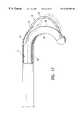
- an elongated deflection linemay be provided in a wall of the delivery member, for deflecting the distal section of the delivery member into a curved or angled condition.
- the inner radius of the extended distal section of the EP deviceis controlled by the length of the elongated opening in the delivery member and the distance the EP device is spaced from the support element.
- the effective length of the elongated openingcan be controlled by the longitudinal location of the distal end of a sheath disposed about the exterior of the delivery member. As the distal end of the sheath extends distally, the effective length of the elongated opening in the distal section of the delivery member is shortened and the radius of curvature of the distal section of the EP device is correspondingly decreased.
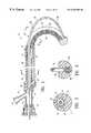
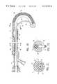
- FIG. 1is an elevational view, partially in section, of a mapping and ablation assembly embodying features of the invention.
- FIG. 2is a transverse cross-sectional view of the assembly shown in FIG. 1 taken along the lines 2 — 2 .
- FIG. 3is a transverse cross-sectional view of the assembly shown in FIG. 1 taken along the lines 3 — 3 .
- FIG. 4is an elevational view, partially in section, of an EP device suitable for use with the assembly shown in FIGS. 1-5.
- FIG. 5is a transverse cross-sectional view of the EP device shown in FIG. 4 taken along the lines 5 — 5 .
- FIG. 6is a longitudinal cross-sectional view of an alternative embodiment similar to that shown in FIG. 1 wherein a lumen is provided to deliver fluid to the distal extremity of the assembly.
- FIG. 7is a transverse cross-sectional view of he assembly shown in FIG. 6 taken along the lines 6 — 6 .
- FIG. 8is a longitudinal cross-sectional view of an alternative embodiment similar to that shown in FIG. 6 with a lumen extending from the proximal end of the assembly to the distal end of the assembly.
- FIG. 9is a transverse cross-sectional view of he assembly shown in FIG. 8 taken along the lines 9 — 9 .
- FIG. 10is a transverse cross-sectional view of he assembly shown in FIG. 8 taken along the lines 10 — 10 .
- FIG. 11is an elevational view, partially in section, of another alternative embodiment wherein the delivery member is provided with electrodes for sensing and/or ablation.
- FIG. 12is a transverse cross-sectional view of the embodiment shown in FIG. 11 taken along the lines 12 — 12 .
- FIG. 13is an elevational view of another embodiment wherein the EP device of the assembly is provided with an inner lumen for delivery of fluid.
- FIG. 14Ais a transverse cross-sectional view of the embodiment shown in FIG. 13 taken along the lines 14 — 14 .
- FIG. 14Bis a transverse cross-sectional view of an alternative embodiment of that shown in FIG. 13 taken along the lines 14 — 14 .
- FIG. 15is an elevational view, partially in section, of a distal section of an alternative embodiment wherein the EP device is provided with an inner lumen for passage of fluid coolant.
- FIG. 16is a transverse cross-sectional view taken along the lines 16 — 16 .
- FIG. 17is an elevational view, partially in section, of a distal section of an alternative embodiment wherein an outer sheath is disposed about the assembly which is longitudinally movable to control the effective length of the elongated opening in the distal section of the delivery member.
- FIG. 18is an elevational view, partially in section, of an alternative embodiment wherein a longitudinally movable flush sheath is provided about the EP device of the assembly to delivery fluid to desired locations on the distal section thereof.
- FIG. 19is a transverse cross-sectional view of the embodiment shown in FIG. 18 taken along the lines 19 — 19 .
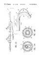
- FIG. 20is an elevational view, partially in section, of a mapping and ablation assembly embodying features of the invention.
- FIG. 21is a transverse cross-sectional view of the assembly shown in FIG. 20 taken along the lines 21 — 21 .
- FIG. 22is a transverse cross-sectional view of the assembly shown in FIG. 1 taken along the lines 22 — 22 .
- FIG. 23is an elevational view, partially in section, of an alternative embodiment of the assembly shown in FIG. 20 having an elongated depression.
- FIG. 24is a transverse cross-sectional view of the assembly shown in FIG. 24 taken along the lines 24 — 24
- FIG. 25Ais an elevational view, partially in section, of the proximal section of an alternative embodiment of the assembly shown in FIG. 20 having a deflection line.
- FIG. 25Bis an elevational view, partially in section, of the distal section of an alternative embodiment of the assembly shown in FIG. 20 having a deflection line.
- FIGS. 26 and 27are transverse cross-sectional view of the assembly shown in FIG. 25 taken along lines 26 — 26 and 27 — 27 , respectively.
- FIG. 28is an elevational view partially in section of a human heart having the assembly shown in FIG. 20 within the right atrium.
- FIG. 29is an elevational view, partially in section, of a distal section of an alternative embodiment of the assembly shown in FIG. 20 wherein an outer sheath is disposed about the assembly which is longitudinally movable to control the effective length of the elongated opening in the distal section of the delivery member.
- the delivery member 11has a proximal shaft section 20 which is formed of a braided tubular structure 21 with a polymer impregnate 22 incorporated therein.
- the braided structure 21may be formed of high strength filaments 23 (e.g. 6 ⁇ 6 strands) such as stainless steel wire with a typical diameter of about 0.003 inch (0.08 mm).
- the polymer impregnateis preferably a thermoplastic polyurethane such as PEBAX 6333.
- An inner lining 24 of high strength polymer material such as polyimidemay be provided which extends to the start of the distal section 25 of the delivery member 11 .
- a supporting ribbon 26extends through the distal section 25 with the proximal extremity thereof about 5 to about 15 mm being secured to the braided tubular structure 21 by suitable means such as solder or adhesive 27 within the wall of the proximal shaft section 30 .
- the supporting ribbon 26is generally about 6 to about 20 cm in total length and has a rectangular transverse cross-section of about 0.003-0.007 inch by 0.01-0.03 inch.
- the distal extremity of the supporting ribbon 26is secured to the distal end of the delivery member 11 in a similar fashion. As shown in FIGS. 1 and 3, the braided tubular structure 21 extends into the distal section 25 of the delivery member 11 disposed about the supporting ribbon 26 .
- the distal section 25 of the delivery member 11has an elongated opening 28 which allows a distal section 31 of the EP device 12 to be extended out and away from the distal section 25 of the delivery member 11 when an axial compressive force is applied to the proximal extremity of the EP device which extends out of the patient during the procedure.
- the length of the elongated opening 28is generally the same length as the distal section 25 , i.e. about 3 to about 20 cm.
- the width of the elongated opening 28generally is greater than the diameter of the distal section 31 of the EP device 12 to allow for the ready outward movement of the EP device.
- the distal section 25 of the delivery member 11is shapeable to a curved configuration with an elongated opening 60 along an inner side of the curved distal section 25 .
- the distal end of the EP device 12is secured within the distal end of the elongated delivery member.
- the distal section 31 of the EP device 12is configured to extended out and away from the distal section 25 of the delivery member 11 through the elongated opening 60 when an axial elongating force is applied to the proximal extremity of the EP device which extends out of the patient during the procedure.
- the elongated opening 28 / 60is omitted and the delivery member 11 has an elongated depression along a side of the curved distal section 25 , and an opening at a proximal end of the depression in fluid communication with the inner lumen 13 .
- the depressionis distal to the lumen 13 containing a proximal section of the EP device 12 , and the EP device distal section 31 extends distally of the lumen 13 out the opening at the proximal end of the depression.
- the distal section 31 of the EP deviceis configured to extend away from the elongated depression when the EP device is displaced relative to the delivery member.
- FIG. 24illustrates a transverse cross-sectional view of the assembly shown in FIG. 23 taken along line 24 — 24 .
- the EP device 12as shown in FIGS. 1 and 4 - 5 includes a proximal shaft section 30 and a distal shaft section 31 .
- the distal shaft section 31has a plurality of mapping/ablation electrodes 32 with each of the electrodes electrically connected to separate electrical conductors 33 (shown in FIGS. 4 - 5 ).
- the electrodes 32are generally not larger than about 1.5 mm ( 4 Fr.), preferably less than 1.3 mm (3.5 Fr.) in outer transverse dimensions.
- the electrode lengthmay vary from about 1 to about 6 mm, preferably about 1 to about 3 mm, and the interelectrode spacing may vary from about 0.5 to about 4 mm, preferably about 0.5 to about 2 mm.
- the electrodes 32may be in the form of metallic cylindrical bands, helical coils, arcuate bands or ribbons and the like.
- the only portion of the electrodes 32 which need exposureare those surfaces which are to be in contact with the inner surface of the heart chamber to detect electrical activity or effect a linear ablation.
- a suitable EP device 12 shown in detail in FIGS. 4 and 5has proximal and distal shaft sections 30 and 31 , an electrical connector 34 on the proximal end of the device and eight electrodes 32 on the distal section 31 which are electrically connected to insulated electrical conductors as in application Ser. No. 09/104,752, entitled EP Catheter, filed Jun. 25, 1998, and Ser. No. 08/188,619, U.S. Pat. No. 5,509,411, entitled Intravascular Sensing Device, filed on Jan. 27, 1994, which are incorporated herein in their entireties by reference.
- Core member 35extends to the distal end of the device which is secured to the distal end of coil 36 by suitable material such as a gold-tin solder (80% Au-20% Sn).
- the coil 36is preferably a 90% Pt-10% Ir wire about 0.005 inch in diameter.
- Polyimide tubing 37about 0.001 inch thick, jackets the core member 35 proximal to the coil 36 which is in turn covered with a fluoropolymer tube 38 such as THV 200G which is available from 3M.
- the braided electrical conductors 33are formed of 36 AWG copper wire with each conductor having a polyimide insulating coating of about 0.0005 inch thick (0.013 mm).
- An equivalent number of polyester fibers 39(e.g. Dacron® from Dupont) are braided with the electrical conductors 33 .
- the braided structure formed by the electrical conductors 33 and the polyester strands 39are covered by an additional fluoropolymer jacket or coating 40 , preferably THV 200 g made by 3M.
- the electrodes 32are helical coils which are preferably formed form 90% Pt-10% Ir wire about 0.005 inch (0.13 mm) in diameter.
- the assembly of the inventionmay be introduced into the patient's vascular system, e.g. the femoral vein, percutaneously or by way of a cut-down, advanced therein and through the inferior vena cava until the distal section 25 is disposed within the right atrium.
- the supporting ribbon 26 in the distal shaft section 31is shaped into a curved configuration so that it assumes the curved configuration when unrestrained within the heart chamber. With the supporting ribbon acting as a supporting surface, a compressive force is applied to the proximal extremity of the EP device which extends out of the patient to urge the device in the distal direction, causing the distal shaft section 31 of the EP device 12 to bow outwardly away from the distal section of the delivery member 11 and the support ribbon 26 therein.
- the EP deviceis displaced proximally relative to the delivery member so that the distal section of the EP device extends through the elongated opening 60 in the distal section of the delivery member.
- the EP device distal sectionis in a curved configuration that follows the curve of the delivery member distal section and extends away from the delivery member distal section to provide good contact against the heart wall.
- Torquing the proximal section 30 of the delivery member 11which extends out of the patient during the procedure, will cause the distal section 25 thereof to be rotatably displaced within the atrial chamber and allow the EP device 12 to be bowed outwardly in a wide variety of directions so electrical activity can be detected in a linear fashion and heart tissue can be linearly ablated at a number of locations within the chamber.
- the typical procedureis to direct the RF current to one or two electrodes at the most distal end of the EP device to perform the first ablation and then continue proximally one or two electrodes at a time until a linear ablation of desired length is obtained in the atrial chamber. This reduces the overall power requirements for the assembly.
- the electrodes 32can be employed to detect electrical activity to ensure that the ablation has been effective in terminating the fibrillation or flutter.
- the electrodes 32are much smaller in diametrical dimensions than prior ablation electrodes which are usually about 1.5 mm or larger. Surprisingly, it has been found that the much smaller electrodes of the present invention provide effective ablation through the atrial wall without the power requirements of the prior electrodes.
- the elongated lesion formed by the linear ablation with the smaller electrodes, while much thinner than lesions formed with the prior larger electrodes,is quite effective in segregating heart tissue so as to terminate the fibrillation or flutter.
- the elongated lesion formed with the device of the present inventionis about 3 to about 12 mm, usually about 5 to about 10 mm, in width.
- FIGS. 6 and 7illustrate an alternative embodiment to that shown in FIGS. 1-3 wherein a second lumen 41 is provided within the distal section of the delivery member in order to pass flushing or cooling fluids to the distal extremity of the delivery member.
- the spacing between the exterior of the EP device 12 and the inner surface of the inner lumen 13 of the delivery member 11is minimized at location 42 so that a significant portion of fluid passing through the inner lumen 13 will pass through port 43 into the inner lumen 41 .
- a discharge port 44is provided in the distal end of the delivery member 11 for discharge of fluid from the inner lumen 41 .
- FIGS. 8-10illustrate another embodiment similar in function to that shown in FIGS. 7-8 which has a second lumen 45 extending the length of the delivery member 11 which is in fluid communication with a second side arm 46 of the adapter 14 .
- the other portions of the embodimentare similar to the embodiment shown in FIGS. 7-8 and are similarly numbered.
- FIGS. 11-12depict yet another embodiment similar in most regards to that shown in FIG. 1 except that the delivery member 11 is provided with a plurality of electrodes 47 on the distal section 25 and at least one electrode 48 on the proximal shaft section 20 .
- the surface of the electrodes 47 on the inside of the curved distal section 25need to be exposed.
- the electrodes 47 and 48may be helical coils as shown or cylindrical tubes or arcuate ribbon or bands provided on the inside curve of the distal section 25 .
- Individual electrical conductorsmay be incorporated into the braided tubular structure 21 and electrically connected by their distal ends to the electrodes 47 and 48 and by their proximal ends to one or more electrical connectors configured to be electrically connected to a high frequency electrical energy source.
- FIGS. 13, 14 A and 14 BAnother alternative embodiment of the invention is shown in FIGS. 13, 14 A and 14 B wherein the EP device 12 is provided with an inner lumen 49 for fluid delivery.
- An adapter 50is secured to the proximal end of the EP device 12 to facilitate introduction of fluid to the inner lumen 49 .
- the lumen 49is off-set from the electrical conductors 51 which are braided about the core 52
- the lumen 49is formed by the braided conductors 51 within a polymer matrix 53 .
- the embodiment of FIG. 14Bdoes not have a core member 52 as in FIG. 14A.
- a discharge port 54is provided in the distal end of the EP device 12 which is in fluid communication with the inner lumen 49 .
- an outer sheath 57may be provided about the exterior of the delivery member to effectively shorten the elongated opening 28 / 60 in the distal section 25 of the delivery member 11 as shown in FIGS. 17 and 29.
- Fluidmay be passed through the inner lumen 58 of the sheath 57 to cool the electrodes 32 during delivery of RF electrical energy.
- a variety of other meansmay be employed to effectively shorten the elongated opening 28 .
- FIGS. 19 and 18illustrate another method of cooling the electrodes 32 on the distal section of the EP device 12 where a flushing sheath 59 is slidably disposed about the EP device.
- the sheath 59can be longitudinally moved along the shaft of the EP device to expose one or more electrodes 32 . Fluid passing over the exposed electrode(s) while electrical energy is being delivered will cool the electrodes sufficiently to avoid thrombus formation.
- electrical energyis not directed to the entire array of electrodes at the same time due to the rather large power requirements for such delivery. Electrical energy is preferably delivered to one or two of the most distal electrodes while fluid is delivered thereto until the lesion of desired length is formed.
- the sheath 59is then pulled proximally to expose additional electrodes 32 , electrical energy is delivered to one or two additionally exposed electrodes while cooling fluid flows out of the distal end of the sheath 59 .
- This procedurecontinues sequentially delivering electrical energy to the more proximal electrodes until a linear ablation of the desired length is formed in the wall of the patient's heart.
- the individual electrodes 32may be used to detect electrical activity after each individual ablation and after the entire linear ablation procedure has been completed to determine if the fibrillation or flutter has been terminated.
Landscapes
- Health & Medical Sciences (AREA)
- Life Sciences & Earth Sciences (AREA)
- Engineering & Computer Science (AREA)
- Veterinary Medicine (AREA)
- Biomedical Technology (AREA)
- Animal Behavior & Ethology (AREA)
- General Health & Medical Sciences (AREA)
- Public Health (AREA)
- Heart & Thoracic Surgery (AREA)
- Pulmonology (AREA)
- Anesthesiology (AREA)
- Hematology (AREA)
- Biophysics (AREA)
- Surgery (AREA)
- Nuclear Medicine, Radiotherapy & Molecular Imaging (AREA)
- Cardiology (AREA)
- Physics & Mathematics (AREA)
- Plasma & Fusion (AREA)
- Otolaryngology (AREA)
- Mechanical Engineering (AREA)
- Medical Informatics (AREA)
- Molecular Biology (AREA)
- Radiology & Medical Imaging (AREA)
- Surgical Instruments (AREA)
Abstract
Description
Claims (26)
Priority Applications (9)
| Application Number | Priority Date | Filing Date | Title |
|---|---|---|---|
| US09/182,967US6302880B1 (en) | 1996-04-08 | 1998-10-29 | Linear ablation assembly |
| EP99971286AEP1119286A4 (en) | 1998-10-29 | 1999-10-25 | Linear ablation assembly |
| JP2000579120AJP2002528213A (en) | 1998-10-29 | 1999-10-25 | Assembly used for linear resection treatment |
| PCT/US1999/024952WO2000025669A1 (en) | 1998-10-29 | 1999-10-25 | Linear ablation assembly |
| AU12289/00AAU1228900A (en) | 1998-10-29 | 1999-10-25 | Linear ablation assembly |
| CA002389517ACA2389517A1 (en) | 1998-10-29 | 1999-10-25 | Linear ablation assembly |
| US09/901,856US6814732B2 (en) | 1996-04-08 | 2001-07-09 | Linear ablation assembly |
| US10/980,699US7331960B2 (en) | 1996-04-08 | 2004-11-03 | Linear ablation assembly |
| US12/070,552US20080287945A1 (en) | 1996-04-08 | 2008-02-19 | Linear ablation assembly |
Applications Claiming Priority (2)
| Application Number | Priority Date | Filing Date | Title |
|---|---|---|---|
| US08/629,057US5863291A (en) | 1996-04-08 | 1996-04-08 | Linear ablation assembly |
| US09/182,967US6302880B1 (en) | 1996-04-08 | 1998-10-29 | Linear ablation assembly |
Related Parent Applications (1)
| Application Number | Title | Priority Date | Filing Date |
|---|---|---|---|
| US08/629,057Continuation-In-PartUS5863291A (en) | 1996-04-08 | 1996-04-08 | Linear ablation assembly |
Related Child Applications (1)
| Application Number | Title | Priority Date | Filing Date |
|---|---|---|---|
| US09/901,856DivisionUS6814732B2 (en) | 1996-04-08 | 2001-07-09 | Linear ablation assembly |
Publications (1)
| Publication Number | Publication Date |
|---|---|
| US6302880B1true US6302880B1 (en) | 2001-10-16 |
Family
ID=22670843
Family Applications (4)
| Application Number | Title | Priority Date | Filing Date |
|---|---|---|---|
| US09/182,967Expired - Fee RelatedUS6302880B1 (en) | 1996-04-08 | 1998-10-29 | Linear ablation assembly |
| US09/901,856Expired - Fee RelatedUS6814732B2 (en) | 1996-04-08 | 2001-07-09 | Linear ablation assembly |
| US10/980,699Expired - Fee RelatedUS7331960B2 (en) | 1996-04-08 | 2004-11-03 | Linear ablation assembly |
| US12/070,552AbandonedUS20080287945A1 (en) | 1996-04-08 | 2008-02-19 | Linear ablation assembly |
Family Applications After (3)
| Application Number | Title | Priority Date | Filing Date |
|---|---|---|---|
| US09/901,856Expired - Fee RelatedUS6814732B2 (en) | 1996-04-08 | 2001-07-09 | Linear ablation assembly |
| US10/980,699Expired - Fee RelatedUS7331960B2 (en) | 1996-04-08 | 2004-11-03 | Linear ablation assembly |
| US12/070,552AbandonedUS20080287945A1 (en) | 1996-04-08 | 2008-02-19 | Linear ablation assembly |
Country Status (6)
| Country | Link |
|---|---|
| US (4) | US6302880B1 (en) |
| EP (1) | EP1119286A4 (en) |
| JP (1) | JP2002528213A (en) |
| AU (1) | AU1228900A (en) |
| CA (1) | CA2389517A1 (en) |
| WO (1) | WO2000025669A1 (en) |
Cited By (101)
| Publication number | Priority date | Publication date | Assignee | Title |
|---|---|---|---|---|
| US20010039418A1 (en)* | 1996-04-08 | 2001-11-08 | Cardima Inc. | Linear ablation assembly |
| US6638245B2 (en) | 2001-06-26 | 2003-10-28 | Concentric Medical, Inc. | Balloon catheter |
| US6645202B1 (en) | 1996-10-22 | 2003-11-11 | Epicor Medical, Inc. | Apparatus and method for ablating tissue |
| US6663622B1 (en)* | 2000-02-11 | 2003-12-16 | Iotek, Inc. | Surgical devices and methods for use in tissue ablation procedures |
| US6689128B2 (en) | 1996-10-22 | 2004-02-10 | Epicor Medical, Inc. | Methods and devices for ablation |
| US6805128B1 (en) | 1996-10-22 | 2004-10-19 | Epicor Medical, Inc. | Apparatus and method for ablating tissue |
| US6840936B2 (en) | 1996-10-22 | 2005-01-11 | Epicor Medical, Inc. | Methods and devices for ablation |
| US6949095B2 (en) | 1996-10-22 | 2005-09-27 | Epicor Medical, Inc. | Apparatus and method for diagnosis and therapy of electrophysiological disease |
| US6976986B2 (en) | 2000-04-12 | 2005-12-20 | Afx, Inc. | Electrode arrangement for use in a medical instrument |
| US7033352B1 (en) | 2000-01-18 | 2006-04-25 | Afx, Inc. | Flexible ablation instrument |
| US7052491B2 (en) | 1998-10-23 | 2006-05-30 | Afx, Inc. | Vacuum-assisted securing apparatus for a microwave ablation instrument |
| US7083620B2 (en) | 2002-10-30 | 2006-08-01 | Medtronic, Inc. | Electrosurgical hemostat |
| US7094235B2 (en) | 2001-04-26 | 2006-08-22 | Medtronic, Inc. | Method and apparatus for tissue ablation |
| US7099717B2 (en) | 2002-01-03 | 2006-08-29 | Afx Inc. | Catheter having improved steering |
| US7118566B2 (en) | 2002-05-16 | 2006-10-10 | Medtronic, Inc. | Device and method for needle-less interstitial injection of fluid for ablation of cardiac tissue |
| US7128740B2 (en) | 1996-05-03 | 2006-10-31 | Jacobs Clemens J | Method for interrupting conduction paths within the heart |
| US7156845B2 (en) | 1998-07-07 | 2007-01-02 | Medtronic, Inc. | Method and apparatus for creating a bi-polar virtual electrode used for the ablation of tissue |
| US7166105B2 (en) | 1995-02-22 | 2007-01-23 | Medtronic, Inc. | Pen-type electrosurgical instrument |
| US7169144B2 (en) | 1998-07-07 | 2007-01-30 | Medtronic, Inc. | Apparatus and method for creating, maintaining, and controlling a virtual electrode used for the ablation of tissue |
| US7192427B2 (en) | 2002-02-19 | 2007-03-20 | Afx, Inc. | Apparatus and method for assessing transmurality of a tissue ablation |
| US7226446B1 (en) | 1999-05-04 | 2007-06-05 | Dinesh Mody | Surgical microwave ablation assembly |
| US7250048B2 (en) | 2001-04-26 | 2007-07-31 | Medtronic, Inc. | Ablation system and method of use |
| US7294143B2 (en) | 2002-05-16 | 2007-11-13 | Medtronic, Inc. | Device and method for ablation of cardiac tissue |
| US7303560B2 (en) | 2000-12-29 | 2007-12-04 | Afx, Inc. | Method of positioning a medical instrument |
| US7309325B2 (en) | 1998-07-07 | 2007-12-18 | Medtronic, Inc. | Helical needle apparatus for creating a virtual electrode used for the ablation of tissue |
| US20070293855A1 (en)* | 2002-02-15 | 2007-12-20 | Sliwa John W Jr | Methods and devices for ablation |
| US20080045946A1 (en)* | 1997-10-15 | 2008-02-21 | Matthias Vaska | Devices and methods for ablating cardiac tissue |
| US7346399B2 (en) | 1999-05-28 | 2008-03-18 | Afx, Inc. | Monopole tip for ablation catheter |
| US7347858B2 (en) | 2001-12-11 | 2008-03-25 | Medtronic, Inc. | Method and system for treatment of atrial tachyarrhythmias |
| US7364578B2 (en) | 2002-01-25 | 2008-04-29 | Medtronic, Inc. | System and method of performing an electrosurgical procedure |
| US7367972B2 (en) | 2001-04-26 | 2008-05-06 | Medtronic, Inc. | Ablation system |
| US7387126B2 (en) | 1996-10-22 | 2008-06-17 | St. Jude Medical, Atrial Fibrillation Division, Inc. | Surgical system and procedure for treatment of medically refractory atrial fibrillation |
| US7429261B2 (en) | 2004-11-24 | 2008-09-30 | Ablation Frontiers, Inc. | Atrial ablation catheter and method of use |
| US7435250B2 (en) | 2000-04-27 | 2008-10-14 | Medtronic, Inc. | Method and apparatus for tissue ablation |
| US7468062B2 (en) | 2004-11-24 | 2008-12-23 | Ablation Frontiers, Inc. | Atrial ablation catheter adapted for treatment of septal wall arrhythmogenic foci and method of use |
| US7470272B2 (en) | 1997-07-18 | 2008-12-30 | Medtronic, Inc. | Device and method for ablating tissue |
| US7497857B2 (en) | 2003-04-29 | 2009-03-03 | Medtronic, Inc. | Endocardial dispersive electrode for use with a monopolar RF ablation pen |
| US7507235B2 (en) | 2001-01-13 | 2009-03-24 | Medtronic, Inc. | Method and system for organ positioning and stabilization |
| US7566334B2 (en) | 2004-06-02 | 2009-07-28 | Medtronic, Inc. | Ablation device with jaws |
| US7615015B2 (en) | 2000-01-19 | 2009-11-10 | Medtronic, Inc. | Focused ultrasound ablation devices having selectively actuatable emitting elements and methods of using the same |
| US7628780B2 (en) | 2001-01-13 | 2009-12-08 | Medtronic, Inc. | Devices and methods for interstitial injection of biologic agents into tissue |
| US7678108B2 (en) | 2004-06-02 | 2010-03-16 | Medtronic, Inc. | Loop ablation apparatus and method |
| US7706894B2 (en) | 2000-10-10 | 2010-04-27 | Medtronic, Inc. | Heart wall ablation/mapping catheter and method |
| US7706882B2 (en) | 2000-01-19 | 2010-04-27 | Medtronic, Inc. | Methods of using high intensity focused ultrasound to form an ablated tissue area |
| US7740623B2 (en) | 2001-01-13 | 2010-06-22 | Medtronic, Inc. | Devices and methods for interstitial injection of biologic agents into tissue |
| US7744562B2 (en) | 2003-01-14 | 2010-06-29 | Medtronics, Inc. | Devices and methods for interstitial injection of biologic agents into tissue |
| US7758580B2 (en) | 2004-06-02 | 2010-07-20 | Medtronic, Inc. | Compound bipolar ablation device and method |
| US7758576B2 (en) | 2004-06-02 | 2010-07-20 | Medtronic, Inc. | Clamping ablation tool and method |
| US7818039B2 (en) | 2000-04-27 | 2010-10-19 | Medtronic, Inc. | Suction stabilized epicardial ablation devices |
| US7824399B2 (en) | 2001-04-26 | 2010-11-02 | Medtronic, Inc. | Ablation system and method of use |
| US7824403B2 (en) | 1996-10-22 | 2010-11-02 | St. Jude Medical, Atrial Fibrillation Division, Inc. | Methods and devices for ablation |
| US7850685B2 (en) | 2005-06-20 | 2010-12-14 | Medtronic Ablation Frontiers Llc | Ablation catheter |
| US7857808B2 (en) | 2002-10-25 | 2010-12-28 | The Regents Of The University Of Michigan | Ablation catheters |
| US7959626B2 (en) | 2001-04-26 | 2011-06-14 | Medtronic, Inc. | Transmural ablation systems and methods |
| US7967816B2 (en) | 2002-01-25 | 2011-06-28 | Medtronic, Inc. | Fluid-assisted electrosurgical instrument with shapeable electrode |
| US8162933B2 (en) | 2000-04-27 | 2012-04-24 | Medtronic, Inc. | Vibration sensitive ablation device and method |
| US8221402B2 (en) | 2000-01-19 | 2012-07-17 | Medtronic, Inc. | Method for guiding a medical device |
| US8308719B2 (en) | 1998-09-21 | 2012-11-13 | St. Jude Medical, Atrial Fibrillation Division, Inc. | Apparatus and method for ablating tissue |
| US8333764B2 (en) | 2004-05-12 | 2012-12-18 | Medtronic, Inc. | Device and method for determining tissue thickness and creating cardiac ablation lesions |
| US8409219B2 (en) | 2004-06-18 | 2013-04-02 | Medtronic, Inc. | Method and system for placement of electrical lead inside heart |
| US8486063B2 (en) | 2004-10-14 | 2013-07-16 | Medtronic Ablation Frontiers Llc | Ablation catheter |
| US8512337B2 (en) | 2001-04-26 | 2013-08-20 | Medtronic, Inc. | Method and system for treatment of atrial tachyarrhythmias |
| US8568409B2 (en) | 2000-03-06 | 2013-10-29 | Medtronic Advanced Energy Llc | Fluid-assisted medical devices, systems and methods |
| US8617152B2 (en) | 2004-11-15 | 2013-12-31 | Medtronic Ablation Frontiers Llc | Ablation system with feedback |
| US8632533B2 (en) | 2009-02-23 | 2014-01-21 | Medtronic Advanced Energy Llc | Fluid-assisted electrosurgical device |
| US8641704B2 (en) | 2007-05-11 | 2014-02-04 | Medtronic Ablation Frontiers Llc | Ablation therapy system and method for treating continuous atrial fibrillation |
| US8657814B2 (en) | 2005-08-22 | 2014-02-25 | Medtronic Ablation Frontiers Llc | User interface for tissue ablation system |
| US8663245B2 (en) | 2004-06-18 | 2014-03-04 | Medtronic, Inc. | Device for occlusion of a left atrial appendage |
| US8801707B2 (en) | 2004-05-14 | 2014-08-12 | Medtronic, Inc. | Method and devices for treating atrial fibrillation by mass ablation |
| US8821488B2 (en) | 2008-05-13 | 2014-09-02 | Medtronic, Inc. | Tissue lesion evaluation |
| US8834461B2 (en) | 2005-07-11 | 2014-09-16 | Medtronic Ablation Frontiers Llc | Low power tissue ablation system |
| US8870864B2 (en) | 2011-10-28 | 2014-10-28 | Medtronic Advanced Energy Llc | Single instrument electrosurgery apparatus and its method of use |
| US8882756B2 (en) | 2007-12-28 | 2014-11-11 | Medtronic Advanced Energy Llc | Fluid-assisted electrosurgical devices, methods and systems |
| US8906012B2 (en) | 2010-06-30 | 2014-12-09 | Medtronic Advanced Energy Llc | Electrosurgical devices with wire electrode |
| US8920417B2 (en) | 2010-06-30 | 2014-12-30 | Medtronic Advanced Energy Llc | Electrosurgical devices and methods of use thereof |
| US8926635B2 (en) | 2004-06-18 | 2015-01-06 | Medtronic, Inc. | Methods and devices for occlusion of an atrial appendage |
| US8932208B2 (en) | 2005-05-26 | 2015-01-13 | Maquet Cardiovascular Llc | Apparatus and methods for performing minimally-invasive surgical procedures |
| US8974445B2 (en) | 2009-01-09 | 2015-03-10 | Recor Medical, Inc. | Methods and apparatus for treatment of cardiac valve insufficiency |
| US9023040B2 (en) | 2010-10-26 | 2015-05-05 | Medtronic Advanced Energy Llc | Electrosurgical cutting devices |
| US9138289B2 (en) | 2010-06-28 | 2015-09-22 | Medtronic Advanced Energy Llc | Electrode sheath for electrosurgical device |
| US9227088B2 (en) | 2006-05-25 | 2016-01-05 | Medtronic, Inc. | Methods of using high intensity focused ultrasound to form an ablated tissue area containing a plurality of lesions |
| US9254168B2 (en) | 2009-02-02 | 2016-02-09 | Medtronic Advanced Energy Llc | Electro-thermotherapy of tissue using penetrating microelectrode array |
| US9314298B2 (en) | 2007-04-17 | 2016-04-19 | St. Jude Medical, Atrial Fibrillation Divisions, Inc. | Vacuum-stabilized ablation system |
| US9333027B2 (en)* | 2010-05-28 | 2016-05-10 | Medtronic Advanced Energy Llc | Method of producing an electrosurgical device |
| US9345541B2 (en) | 2009-09-08 | 2016-05-24 | Medtronic Advanced Energy Llc | Cartridge assembly for electrosurgical devices, electrosurgical unit and methods of use thereof |
| US9381061B2 (en) | 2000-03-06 | 2016-07-05 | Medtronic Advanced Energy Llc | Fluid-assisted medical devices, systems and methods |
| US9427281B2 (en) | 2011-03-11 | 2016-08-30 | Medtronic Advanced Energy Llc | Bronchoscope-compatible catheter provided with electrosurgical device |
| US9592090B2 (en) | 2010-03-11 | 2017-03-14 | Medtronic Advanced Energy Llc | Bipolar electrosurgical cutter with position insensitive return electrode contact |
| US9700372B2 (en) | 2002-07-01 | 2017-07-11 | Recor Medical, Inc. | Intraluminal methods of ablating nerve tissue |
| US9750565B2 (en) | 2011-09-30 | 2017-09-05 | Medtronic Advanced Energy Llc | Electrosurgical balloons |
| US9956029B2 (en) | 2014-10-31 | 2018-05-01 | Medtronic Advanced Energy Llc | Telescoping device with saline irrigation line |
| US9974599B2 (en) | 2014-08-15 | 2018-05-22 | Medtronic Ps Medical, Inc. | Multipurpose electrosurgical device |
| US10058380B2 (en) | 2007-10-05 | 2018-08-28 | Maquet Cordiovascular Llc | Devices and methods for minimally-invasive surgical procedures |
| US10194975B1 (en) | 2017-07-11 | 2019-02-05 | Medtronic Advanced Energy, Llc | Illuminated and isolated electrosurgical apparatus |
| US10631914B2 (en) | 2013-09-30 | 2020-04-28 | Covidien Lp | Bipolar electrosurgical instrument with movable electrode and related systems and methods |
| US10743932B2 (en) | 2011-07-28 | 2020-08-18 | Biosense Webster (Israel) Ltd. | Integrated ablation system using catheter with multiple irrigation lumens |
| US10792467B2 (en)* | 2014-12-05 | 2020-10-06 | Edwards Lifesciences Corporation | Steerable catheter with pull wire |
| CN112704560A (en)* | 2019-10-24 | 2021-04-27 | 斯塔尔麦德有限公司 | Medical device for perforation |
| US11051875B2 (en) | 2015-08-24 | 2021-07-06 | Medtronic Advanced Energy Llc | Multipurpose electrosurgical device |
| US11234760B2 (en) | 2012-10-05 | 2022-02-01 | Medtronic Advanced Energy Llc | Electrosurgical device for cutting and removing tissue |
| US11389227B2 (en) | 2015-08-20 | 2022-07-19 | Medtronic Advanced Energy Llc | Electrosurgical device with multivariate control |
Families Citing this family (59)
| Publication number | Priority date | Publication date | Assignee | Title |
|---|---|---|---|---|
| US6306132B1 (en)* | 1999-06-17 | 2001-10-23 | Vivant Medical | Modular biopsy and microwave ablation needle delivery apparatus adapted to in situ assembly and method of use |
| US7197363B2 (en) | 2002-04-16 | 2007-03-27 | Vivant Medical, Inc. | Microwave antenna having a curved configuration |
| US6752767B2 (en)* | 2002-04-16 | 2004-06-22 | Vivant Medical, Inc. | Localization element with energized tip |
| US8956280B2 (en) | 2002-05-30 | 2015-02-17 | Intuitive Surgical Operations, Inc. | Apparatus and methods for placing leads using direct visualization |
| US20050033137A1 (en)* | 2002-10-25 | 2005-02-10 | The Regents Of The University Of Michigan | Ablation catheters and methods for their use |
| US7311703B2 (en) | 2003-07-18 | 2007-12-25 | Vivant Medical, Inc. | Devices and methods for cooling microwave antennas |
| WO2005023358A1 (en)* | 2003-09-03 | 2005-03-17 | Acumen Medical, Inc. | Expandable sheath for delivering instruments and agents into a body lumen |
| US20050228452A1 (en)* | 2004-02-11 | 2005-10-13 | Mourlas Nicholas J | Steerable catheters and methods for using them |
| US7467015B2 (en) | 2004-04-29 | 2008-12-16 | Neuwave Medical, Inc. | Segmented catheter for tissue ablation |
| US20070016180A1 (en)* | 2004-04-29 | 2007-01-18 | Lee Fred T Jr | Microwave surgical device |
| US20070016181A1 (en) | 2004-04-29 | 2007-01-18 | Van Der Weide Daniel W | Microwave tissue resection tool |
| US7244254B2 (en)* | 2004-04-29 | 2007-07-17 | Micrablate | Air-core microwave ablation antennas |
| US20060276781A1 (en)* | 2004-04-29 | 2006-12-07 | Van Der Weide Daniel W | Cannula cooling and positioning device |
| US7276064B2 (en)* | 2004-05-27 | 2007-10-02 | St. Jude Medical, Atrial Fibrillation Division, Inc. | Side-port sheath for catheter placement and translation |
| US7993350B2 (en) | 2004-10-04 | 2011-08-09 | Medtronic, Inc. | Shapeable or steerable guide sheaths and methods for making and using them |
| US7875049B2 (en)* | 2004-10-04 | 2011-01-25 | Medtronic, Inc. | Expandable guide sheath with steerable backbone and methods for making and using them |
| DE102004058008B4 (en)* | 2004-12-01 | 2007-08-23 | Siemens Ag | Guidewire for vascular catheter with improved tracking and navigation |
| US7575569B2 (en)* | 2005-08-16 | 2009-08-18 | Medtronic, Inc. | Apparatus and methods for delivering stem cells and other agents into cardiac tissue |
| US7637902B2 (en)* | 2005-11-23 | 2009-12-29 | Medtronic, Inc. | Slittable and peelable sheaths and methods for making and using them |
| EP2001383A4 (en)* | 2006-03-17 | 2011-01-19 | Microcube Llc | Devices and methods for creating continuous lesions |
| US8672932B2 (en) | 2006-03-24 | 2014-03-18 | Neuwave Medical, Inc. | Center fed dipole for use with tissue ablation systems, devices and methods |
| US10363092B2 (en) | 2006-03-24 | 2019-07-30 | Neuwave Medical, Inc. | Transmission line with heat transfer ability |
| EP1998699A1 (en)* | 2006-03-24 | 2008-12-10 | Neuwave Medical, Inc. | Energy delivery system |
| US7678109B2 (en)* | 2006-06-23 | 2010-03-16 | St. Jude Medical, Atrial Fibrillation Division, Inc. | Ablation device and method comprising movable ablation elements |
| US11389235B2 (en) | 2006-07-14 | 2022-07-19 | Neuwave Medical, Inc. | Energy delivery systems and uses thereof |
| US10376314B2 (en) | 2006-07-14 | 2019-08-13 | Neuwave Medical, Inc. | Energy delivery systems and uses thereof |
| US8068921B2 (en)* | 2006-09-29 | 2011-11-29 | Vivant Medical, Inc. | Microwave antenna assembly and method of using the same |
| US8292880B2 (en)* | 2007-11-27 | 2012-10-23 | Vivant Medical, Inc. | Targeted cooling of deployable microwave antenna |
| US8882761B2 (en)* | 2008-07-15 | 2014-11-11 | Catheffects, Inc. | Catheter and method for improved ablation |
| US20100191232A1 (en)* | 2009-01-27 | 2010-07-29 | Boveda Marco Medical Llc | Catheters and methods for performing electrophysiological interventions |
| US8954161B2 (en) | 2012-06-01 | 2015-02-10 | Advanced Cardiac Therapeutics, Inc. | Systems and methods for radiometrically measuring temperature and detecting tissue contact prior to and during tissue ablation |
| US8926605B2 (en) | 2012-02-07 | 2015-01-06 | Advanced Cardiac Therapeutics, Inc. | Systems and methods for radiometrically measuring temperature during tissue ablation |
| US9277961B2 (en) | 2009-06-12 | 2016-03-08 | Advanced Cardiac Therapeutics, Inc. | Systems and methods of radiometrically determining a hot-spot temperature of tissue being treated |
| US9226791B2 (en) | 2012-03-12 | 2016-01-05 | Advanced Cardiac Therapeutics, Inc. | Systems for temperature-controlled ablation using radiometric feedback |
| AU2010266027B2 (en)* | 2009-06-24 | 2015-05-07 | Shifamed Holdings, Llc | Steerable medical delivery devices and methods of use |
| EP3549544B1 (en) | 2009-07-28 | 2021-01-06 | Neuwave Medical, Inc. | DEVICE FOR ABLATION |
| ES2856026T3 (en) | 2010-05-03 | 2021-09-27 | Neuwave Medical Inc | Power supply systems |
| US9192438B2 (en) | 2011-12-21 | 2015-11-24 | Neuwave Medical, Inc. | Energy delivery systems and uses thereof |
| WO2014045332A1 (en)* | 2012-09-18 | 2014-03-27 | テルモ株式会社 | Puncturing tool |
| US9549666B2 (en) | 2012-11-10 | 2017-01-24 | Curvo Medical, Inc. | Coaxial micro-endoscope |
| US9233225B2 (en)* | 2012-11-10 | 2016-01-12 | Curvo Medical, Inc. | Coaxial bi-directional catheter |
| US20150342668A1 (en) | 2013-02-21 | 2015-12-03 | Stryker Corporation | Tissue ablation cannula and elecgtrode assembly that can be selectively operated with one or more active tips |
| ES2681970T3 (en)* | 2013-02-21 | 2018-09-17 | Stryker Corporation | Cannula and tissue removal electrode assembly that can be selectively operated with one or more active tips |
| JP6725178B2 (en) | 2014-11-19 | 2020-07-15 | エピックス セラピューティクス,インコーポレイテッド | Ablation apparatus, systems and methods using high resolution electrode assemblies |
| JP6825789B2 (en) | 2014-11-19 | 2021-02-03 | エピックス セラピューティクス,インコーポレイテッド | Systems and methods for high resolution mapping of tissues |
| WO2016081611A1 (en) | 2014-11-19 | 2016-05-26 | Advanced Cardiac Therapeutics, Inc. | High-resolution mapping of tissue with pacing |
| US9636164B2 (en) | 2015-03-25 | 2017-05-02 | Advanced Cardiac Therapeutics, Inc. | Contact sensing systems and methods |
| US10420537B2 (en) | 2015-03-27 | 2019-09-24 | Shifamed Holdings, Llc | Steerable medical devices, systems, and methods of use |
| US10154905B2 (en) | 2015-08-07 | 2018-12-18 | Medtronic Vascular, Inc. | System and method for deflecting a delivery catheter |
| CN113367788B (en) | 2015-10-26 | 2024-09-06 | 纽韦弗医疗设备公司 | Energy delivery systems and uses thereof |
| WO2017160808A1 (en) | 2016-03-15 | 2017-09-21 | Advanced Cardiac Therapeutics, Inc. | Improved devices, systems and methods for irrigated ablation |
| US10531917B2 (en) | 2016-04-15 | 2020-01-14 | Neuwave Medical, Inc. | Systems and methods for energy delivery |
| EP3522807B1 (en) | 2016-10-04 | 2025-07-09 | Avent, Inc. | Cooled rf probes |
| CN110809448B (en) | 2017-04-27 | 2022-11-25 | Epix疗法公司 | Determining properties of contact between catheter tip and tissue |
| US11672596B2 (en) | 2018-02-26 | 2023-06-13 | Neuwave Medical, Inc. | Energy delivery devices with flexible and adjustable tips |
| US11832880B2 (en) | 2018-12-13 | 2023-12-05 | Neuwave Medical, Inc. | Energy delivery devices and related systems and methods thereof |
| US11832879B2 (en) | 2019-03-08 | 2023-12-05 | Neuwave Medical, Inc. | Systems and methods for energy delivery |
| DE102019112290A1 (en) | 2019-05-10 | 2020-11-12 | Trw Automotive Gmbh | Airbag ventilation device and vehicle seat |
| EP4240460A4 (en) | 2020-11-09 | 2024-05-08 | Agile Devices, Inc. | CATHETER CONTROL DEVICES |
Citations (22)
| Publication number | Priority date | Publication date | Assignee | Title |
|---|---|---|---|---|
| US3910279A (en) | 1973-06-20 | 1975-10-07 | Olympus Optical Co | Electrosurgical instrument |
| WO1992019167A1 (en) | 1991-04-26 | 1992-11-12 | Mentor O&O Inc. | Eye surgery performed with an electrosurgical instrument |
| US5163938A (en) | 1990-07-19 | 1992-11-17 | Olympus Optical Co., Ltd. | High-frequency surgical treating device for use with endoscope |
| EP0554722A1 (en) | 1990-01-10 | 1993-08-11 | Sakharam Dhundiraj Mahurkar | Reinforced multiple-lumen catheter |
| US5242441A (en) | 1992-02-24 | 1993-09-07 | Boaz Avitall | Deflectable catheter with rotatable tip electrode |
| US5242443A (en) | 1991-08-15 | 1993-09-07 | Smith & Nephew Dyonics, Inc. | Percutaneous fixation of vertebrae |
| US5263493A (en) | 1992-02-24 | 1993-11-23 | Boaz Avitall | Deflectable loop electrode array mapping and ablation catheter for cardiac chambers |
| US5313943A (en) | 1992-09-25 | 1994-05-24 | Ep Technologies, Inc. | Catheters and methods for performing cardiac diagnosis and treatment |
| US5323768A (en) | 1991-04-22 | 1994-06-28 | Olympus Optical Co., Ltd. | Diathermic dissector with a bifurcation having substantially the same cross-sectional area as a lumen for guiding a wire |
| EP0609182A1 (en) | 1993-01-18 | 1994-08-03 | X-TRODE S.r.l. | An electrode catheter for mapping and operating on cardiac cavities |
| WO1994016619A1 (en) | 1993-01-29 | 1994-08-04 | Cardima, Inc. | Method intravascular sensing devices for electrical activity |
| US5341807A (en) | 1992-06-30 | 1994-08-30 | American Cardiac Ablation Co., Inc. | Ablation catheter positioning system |
| US5363861A (en) | 1991-11-08 | 1994-11-15 | Ep Technologies, Inc. | Electrode tip assembly with variable resistance to bending |
| WO1995010322A1 (en) | 1993-10-15 | 1995-04-20 | Ep Technologies, Inc. | Creating complex lesion patterns in body tissue |
| WO1995015115A1 (en) | 1993-12-03 | 1995-06-08 | Boaz Avitall | Atrial mapping and ablation catheter system |
| US5431696A (en) | 1992-10-13 | 1995-07-11 | Atlee, Iii; John L. | Esophageal probe for transeophageal cardiac stimulation |
| US5454370A (en) | 1993-12-03 | 1995-10-03 | Avitall; Boaz | Mapping and ablation electrode configuration |
| WO1995034259A1 (en) | 1994-06-14 | 1995-12-21 | Desai Ashvin H | Endoscopic surgical instrument |
| US5555883A (en) | 1992-02-24 | 1996-09-17 | Avitall; Boaz | Loop electrode array mapping and ablation catheter for cardiac chambers |
| WO1997037607A2 (en) | 1996-04-08 | 1997-10-16 | Cardima, Inc. | Linear ablation device and assembly |
| US5863291A (en) | 1996-04-08 | 1999-01-26 | Cardima, Inc. | Linear ablation assembly |
| US6001093A (en) | 1993-10-15 | 1999-12-14 | Ep Technologies, Inc. | Systems and methods for creating long, thin lesions in body tissue |
Family Cites Families (8)
| Publication number | Priority date | Publication date | Assignee | Title |
|---|---|---|---|---|
| CA2174129C (en)* | 1993-10-14 | 2004-03-09 | Sidney D. Fleischman | Electrode elements for forming lesion patterns |
| US6071274A (en)* | 1996-12-19 | 2000-06-06 | Ep Technologies, Inc. | Loop structures for supporting multiple electrode elements |
| US6302880B1 (en)* | 1996-04-08 | 2001-10-16 | Cardima, Inc. | Linear ablation assembly |
| US6071279A (en)* | 1996-12-19 | 2000-06-06 | Ep Technologies, Inc. | Branched structures for supporting multiple electrode elements |
| US7070595B2 (en)* | 1998-12-14 | 2006-07-04 | Medwaves, Inc. | Radio-frequency based catheter system and method for ablating biological tissues |
| US6916306B1 (en)* | 2000-11-10 | 2005-07-12 | Boston Scientific Scimed, Inc. | Steerable loop structures for supporting diagnostic and therapeutic elements in contact with body tissue |
| US7785323B2 (en)* | 2000-12-04 | 2010-08-31 | Boston Scientific Scimed, Inc. | Loop structure including inflatable therapeutic device |
| CN100508910C (en)* | 2001-11-29 | 2009-07-08 | 麦迪威公司 | Radio frequency based catheter system with improved deflection and steering mechanism |
- 1998
- 1998-10-29USUS09/182,967patent/US6302880B1/ennot_activeExpired - Fee Related
- 1999
- 1999-10-25WOPCT/US1999/024952patent/WO2000025669A1/enactiveApplication Filing
- 1999-10-25AUAU12289/00Apatent/AU1228900A/ennot_activeAbandoned
- 1999-10-25JPJP2000579120Apatent/JP2002528213A/enactivePending
- 1999-10-25EPEP99971286Apatent/EP1119286A4/ennot_activeWithdrawn
- 1999-10-25CACA002389517Apatent/CA2389517A1/ennot_activeAbandoned
- 2001
- 2001-07-09USUS09/901,856patent/US6814732B2/ennot_activeExpired - Fee Related
- 2004
- 2004-11-03USUS10/980,699patent/US7331960B2/ennot_activeExpired - Fee Related
- 2008
- 2008-02-19USUS12/070,552patent/US20080287945A1/ennot_activeAbandoned
Patent Citations (25)
| Publication number | Priority date | Publication date | Assignee | Title |
|---|---|---|---|---|
| US3910279A (en) | 1973-06-20 | 1975-10-07 | Olympus Optical Co | Electrosurgical instrument |
| EP0554722A1 (en) | 1990-01-10 | 1993-08-11 | Sakharam Dhundiraj Mahurkar | Reinforced multiple-lumen catheter |
| US5163938A (en) | 1990-07-19 | 1992-11-17 | Olympus Optical Co., Ltd. | High-frequency surgical treating device for use with endoscope |
| US5323768A (en) | 1991-04-22 | 1994-06-28 | Olympus Optical Co., Ltd. | Diathermic dissector with a bifurcation having substantially the same cross-sectional area as a lumen for guiding a wire |
| WO1992019167A1 (en) | 1991-04-26 | 1992-11-12 | Mentor O&O Inc. | Eye surgery performed with an electrosurgical instrument |
| US5242443A (en) | 1991-08-15 | 1993-09-07 | Smith & Nephew Dyonics, Inc. | Percutaneous fixation of vertebrae |
| US5363861A (en) | 1991-11-08 | 1994-11-15 | Ep Technologies, Inc. | Electrode tip assembly with variable resistance to bending |
| US5263493A (en) | 1992-02-24 | 1993-11-23 | Boaz Avitall | Deflectable loop electrode array mapping and ablation catheter for cardiac chambers |
| US5555883A (en) | 1992-02-24 | 1996-09-17 | Avitall; Boaz | Loop electrode array mapping and ablation catheter for cardiac chambers |
| US5242441A (en) | 1992-02-24 | 1993-09-07 | Boaz Avitall | Deflectable catheter with rotatable tip electrode |
| US5341807A (en) | 1992-06-30 | 1994-08-30 | American Cardiac Ablation Co., Inc. | Ablation catheter positioning system |
| US5313943A (en) | 1992-09-25 | 1994-05-24 | Ep Technologies, Inc. | Catheters and methods for performing cardiac diagnosis and treatment |
| US5431696A (en) | 1992-10-13 | 1995-07-11 | Atlee, Iii; John L. | Esophageal probe for transeophageal cardiac stimulation |
| US5482037A (en) | 1993-01-18 | 1996-01-09 | X-Trode S.R.L. | Electrode catheter for mapping and operating on cardiac cavities |
| EP0609182A1 (en) | 1993-01-18 | 1994-08-03 | X-TRODE S.r.l. | An electrode catheter for mapping and operating on cardiac cavities |
| WO1994016619A1 (en) | 1993-01-29 | 1994-08-04 | Cardima, Inc. | Method intravascular sensing devices for electrical activity |
| WO1995010322A1 (en) | 1993-10-15 | 1995-04-20 | Ep Technologies, Inc. | Creating complex lesion patterns in body tissue |
| US6001093A (en) | 1993-10-15 | 1999-12-14 | Ep Technologies, Inc. | Systems and methods for creating long, thin lesions in body tissue |
| US5454370A (en) | 1993-12-03 | 1995-10-03 | Avitall; Boaz | Mapping and ablation electrode configuration |
| US5487385A (en) | 1993-12-03 | 1996-01-30 | Avitall; Boaz | Atrial mapping and ablation catheter system |
| US5687723A (en) | 1993-12-03 | 1997-11-18 | Avitall; Boaz | Mapping and ablation catheter system |
| WO1995015115A1 (en) | 1993-12-03 | 1995-06-08 | Boaz Avitall | Atrial mapping and ablation catheter system |
| WO1995034259A1 (en) | 1994-06-14 | 1995-12-21 | Desai Ashvin H | Endoscopic surgical instrument |
| WO1997037607A2 (en) | 1996-04-08 | 1997-10-16 | Cardima, Inc. | Linear ablation device and assembly |
| US5863291A (en) | 1996-04-08 | 1999-01-26 | Cardima, Inc. | Linear ablation assembly |
Cited By (177)
| Publication number | Priority date | Publication date | Assignee | Title |
|---|---|---|---|---|
| US7794460B2 (en) | 1995-02-22 | 2010-09-14 | Medtronic, Inc. | Method of ablating tissue |
| US7422588B2 (en) | 1995-02-22 | 2008-09-09 | Medtronic, Inc. | Pen-type electrosurgical instrument |
| US7247155B2 (en) | 1995-02-22 | 2007-07-24 | Medtronic, Inc. | Apparatus and method for creating, maintaining, and controlling a virtual electrode used for the ablation of tissue |
| US7166105B2 (en) | 1995-02-22 | 2007-01-23 | Medtronic, Inc. | Pen-type electrosurgical instrument |
| US9770282B2 (en) | 1995-02-22 | 2017-09-26 | Medtronic, Inc. | Apparatus and method for creating, maintaining, and controlling a virtual electrode used for the ablation of tissue |
| US20080287945A1 (en)* | 1996-04-08 | 2008-11-20 | Alan K Schaer | Linear ablation assembly |
| US20050065512A1 (en)* | 1996-04-08 | 2005-03-24 | Cardima, Inc. | Linear ablation assembly |
| US7331960B2 (en)* | 1996-04-08 | 2008-02-19 | Cardima, Inc. | Linear ablation assembly |
| US20010039418A1 (en)* | 1996-04-08 | 2001-11-08 | Cardima Inc. | Linear ablation assembly |
| US6814732B2 (en)* | 1996-04-08 | 2004-11-09 | Cardima, Inc. | Linear ablation assembly |
| US7128740B2 (en) | 1996-05-03 | 2006-10-31 | Jacobs Clemens J | Method for interrupting conduction paths within the heart |
| US7674257B2 (en) | 1996-10-22 | 2010-03-09 | St. Jude Medical, Atrial Fibrillation Division, Inc. | Apparatus and method for ablating tissue |
| US7387126B2 (en) | 1996-10-22 | 2008-06-17 | St. Jude Medical, Atrial Fibrillation Division, Inc. | Surgical system and procedure for treatment of medically refractory atrial fibrillation |
| US6840936B2 (en) | 1996-10-22 | 2005-01-11 | Epicor Medical, Inc. | Methods and devices for ablation |
| US6949095B2 (en) | 1996-10-22 | 2005-09-27 | Epicor Medical, Inc. | Apparatus and method for diagnosis and therapy of electrophysiological disease |
| US6971394B2 (en) | 1996-10-22 | 2005-12-06 | Epicor Medical, Inc. | Methods and devices for ablation |
| US7824403B2 (en) | 1996-10-22 | 2010-11-02 | St. Jude Medical, Atrial Fibrillation Division, Inc. | Methods and devices for ablation |
| US6701931B2 (en) | 1996-10-22 | 2004-03-09 | Epicor Medical, Inc. | Methods and devices for ablation |
| US8114069B2 (en) | 1996-10-22 | 2012-02-14 | St. Jude Medical, Atrial Fibrillation Division, Inc. | Methods and devices for ablation |
| US6689128B2 (en) | 1996-10-22 | 2004-02-10 | Epicor Medical, Inc. | Methods and devices for ablation |
| US8721636B2 (en) | 1996-10-22 | 2014-05-13 | St. Jude Medical, Atrial Fibrillation Division, Inc. | Apparatus and method for diagnosis and therapy of electrophysiological disease |
| US7338486B2 (en) | 1996-10-22 | 2008-03-04 | St. Jude Medical, Atrial Fibrillation Division, Inc. | Methods and devices for ablation |
| US6719755B2 (en) | 1996-10-22 | 2004-04-13 | Epicor Medical, Inc. | Methods and devices for ablation |
| US8535301B2 (en) | 1996-10-22 | 2013-09-17 | St. Jude Medical, Atrial Fibrillation Division, Inc. | Surgical system and procedure for treatment of medically refractory atrial fibrillation |
| US6805128B1 (en) | 1996-10-22 | 2004-10-19 | Epicor Medical, Inc. | Apparatus and method for ablating tissue |
| US6805129B1 (en) | 1996-10-22 | 2004-10-19 | Epicor Medical, Inc. | Apparatus and method for ablating tissue |
| US6858026B2 (en) | 1996-10-22 | 2005-02-22 | Epicor Medical, Inc. | Methods and devices for ablation |
| US8057465B2 (en) | 1996-10-22 | 2011-11-15 | St. Jude Medical, Atrial Fibrillation Division, Inc. | Methods and devices for ablation |
| US8002771B2 (en) | 1996-10-22 | 2011-08-23 | St. Jude Medical, Atrial Fibrillation Division, Inc. | Surgical system and procedure for treatment of medically refractory atrial fibrillation |
| US6645202B1 (en) | 1996-10-22 | 2003-11-11 | Epicor Medical, Inc. | Apparatus and method for ablating tissue |
| US7470272B2 (en) | 1997-07-18 | 2008-12-30 | Medtronic, Inc. | Device and method for ablating tissue |
| US7678111B2 (en) | 1997-07-18 | 2010-03-16 | Medtronic, Inc. | Device and method for ablating tissue |
| US20080045946A1 (en)* | 1997-10-15 | 2008-02-21 | Matthias Vaska | Devices and methods for ablating cardiac tissue |
| US8709007B2 (en)* | 1997-10-15 | 2014-04-29 | St. Jude Medical, Atrial Fibrillation Division, Inc. | Devices and methods for ablating cardiac tissue |
| US9113896B2 (en) | 1998-07-07 | 2015-08-25 | Medtronic, Inc. | Method and apparatus for creating a bi-polar virtual electrode used for the ablation of tissue |
| US7169144B2 (en) | 1998-07-07 | 2007-01-30 | Medtronic, Inc. | Apparatus and method for creating, maintaining, and controlling a virtual electrode used for the ablation of tissue |
| US7156845B2 (en) | 1998-07-07 | 2007-01-02 | Medtronic, Inc. | Method and apparatus for creating a bi-polar virtual electrode used for the ablation of tissue |
| US7309325B2 (en) | 1998-07-07 | 2007-12-18 | Medtronic, Inc. | Helical needle apparatus for creating a virtual electrode used for the ablation of tissue |
| US7699805B2 (en) | 1998-07-07 | 2010-04-20 | Medtronic, Inc. | Helical coil apparatus for ablation of tissue |
| US8308719B2 (en) | 1998-09-21 | 2012-11-13 | St. Jude Medical, Atrial Fibrillation Division, Inc. | Apparatus and method for ablating tissue |
| US7052491B2 (en) | 1998-10-23 | 2006-05-30 | Afx, Inc. | Vacuum-assisted securing apparatus for a microwave ablation instrument |
| US7387627B2 (en) | 1998-10-23 | 2008-06-17 | Maquet Cardiovascular Llc | Vacuum-assisted securing apparatus for a microwave ablation instrument |
| US7115126B2 (en) | 1998-10-23 | 2006-10-03 | Afx Inc. | Directional microwave ablation instrument with off-set energy delivery portion |
| US7226446B1 (en) | 1999-05-04 | 2007-06-05 | Dinesh Mody | Surgical microwave ablation assembly |
| US7346399B2 (en) | 1999-05-28 | 2008-03-18 | Afx, Inc. | Monopole tip for ablation catheter |
| US9055959B2 (en) | 1999-07-19 | 2015-06-16 | St. Jude Medical, Atrial Fibrillation Division, Inc. | Methods and devices for ablation |
| US7301131B2 (en) | 2000-01-18 | 2007-11-27 | Afx, Inc. | Microwave ablation instrument with flexible antenna assembly and method |
| US7033352B1 (en) | 2000-01-18 | 2006-04-25 | Afx, Inc. | Flexible ablation instrument |
| US7615015B2 (en) | 2000-01-19 | 2009-11-10 | Medtronic, Inc. | Focused ultrasound ablation devices having selectively actuatable emitting elements and methods of using the same |
| US7706882B2 (en) | 2000-01-19 | 2010-04-27 | Medtronic, Inc. | Methods of using high intensity focused ultrasound to form an ablated tissue area |
| US8221402B2 (en) | 2000-01-19 | 2012-07-17 | Medtronic, Inc. | Method for guiding a medical device |
| US6663622B1 (en)* | 2000-02-11 | 2003-12-16 | Iotek, Inc. | Surgical devices and methods for use in tissue ablation procedures |
| US20040073206A1 (en)* | 2000-02-11 | 2004-04-15 | Iotek, Inc. | Surgical devices and methods for use in tissue ablation procedures |
| US8568409B2 (en) | 2000-03-06 | 2013-10-29 | Medtronic Advanced Energy Llc | Fluid-assisted medical devices, systems and methods |
| US9381061B2 (en) | 2000-03-06 | 2016-07-05 | Medtronic Advanced Energy Llc | Fluid-assisted medical devices, systems and methods |
| US7156841B2 (en) | 2000-04-12 | 2007-01-02 | Afx, Inc. | Electrode arrangement for use in a medical instrument |
| US6976986B2 (en) | 2000-04-12 | 2005-12-20 | Afx, Inc. | Electrode arrangement for use in a medical instrument |
| US7435250B2 (en) | 2000-04-27 | 2008-10-14 | Medtronic, Inc. | Method and apparatus for tissue ablation |
| US8162933B2 (en) | 2000-04-27 | 2012-04-24 | Medtronic, Inc. | Vibration sensitive ablation device and method |
| US9693819B2 (en) | 2000-04-27 | 2017-07-04 | Medtronic, Inc. | Vibration sensitive ablation device and method |
| US7818039B2 (en) | 2000-04-27 | 2010-10-19 | Medtronic, Inc. | Suction stabilized epicardial ablation devices |
| US8706260B2 (en) | 2000-10-10 | 2014-04-22 | Medtronic, Inc. | Heart wall ablation/mapping catheter and method |
| US7706894B2 (en) | 2000-10-10 | 2010-04-27 | Medtronic, Inc. | Heart wall ablation/mapping catheter and method |
| US7303560B2 (en) | 2000-12-29 | 2007-12-04 | Afx, Inc. | Method of positioning a medical instrument |
| US7507235B2 (en) | 2001-01-13 | 2009-03-24 | Medtronic, Inc. | Method and system for organ positioning and stabilization |
| US7740623B2 (en) | 2001-01-13 | 2010-06-22 | Medtronic, Inc. | Devices and methods for interstitial injection of biologic agents into tissue |
| US7628780B2 (en) | 2001-01-13 | 2009-12-08 | Medtronic, Inc. | Devices and methods for interstitial injection of biologic agents into tissue |
| US8221415B2 (en) | 2001-04-26 | 2012-07-17 | Medtronic, Inc. | Method and apparatus for tissue ablation |
| US8262649B2 (en) | 2001-04-26 | 2012-09-11 | Medtronic, Inc. | Method and apparatus for tissue ablation |
| US7959626B2 (en) | 2001-04-26 | 2011-06-14 | Medtronic, Inc. | Transmural ablation systems and methods |
| US7094235B2 (en) | 2001-04-26 | 2006-08-22 | Medtronic, Inc. | Method and apparatus for tissue ablation |
| US7824399B2 (en) | 2001-04-26 | 2010-11-02 | Medtronic, Inc. | Ablation system and method of use |
| US7250048B2 (en) | 2001-04-26 | 2007-07-31 | Medtronic, Inc. | Ablation system and method of use |
| US8512337B2 (en) | 2001-04-26 | 2013-08-20 | Medtronic, Inc. | Method and system for treatment of atrial tachyarrhythmias |
| US7250051B2 (en) | 2001-04-26 | 2007-07-31 | Medtronic, Inc. | Method and apparatus for tissue ablation |
| US7367972B2 (en) | 2001-04-26 | 2008-05-06 | Medtronic, Inc. | Ablation system |
| US7766049B2 (en) | 2001-06-26 | 2010-08-03 | Concentric Medical, Inc. | Balloon catheter |
| US6638245B2 (en) | 2001-06-26 | 2003-10-28 | Concentric Medical, Inc. | Balloon catheter |
| US7347858B2 (en) | 2001-12-11 | 2008-03-25 | Medtronic, Inc. | Method and system for treatment of atrial tachyarrhythmias |
| US7099717B2 (en) | 2002-01-03 | 2006-08-29 | Afx Inc. | Catheter having improved steering |
| US7967816B2 (en) | 2002-01-25 | 2011-06-28 | Medtronic, Inc. | Fluid-assisted electrosurgical instrument with shapeable electrode |
| US7364578B2 (en) | 2002-01-25 | 2008-04-29 | Medtronic, Inc. | System and method of performing an electrosurgical procedure |
| US8623010B2 (en) | 2002-01-25 | 2014-01-07 | Medtronic, Inc. | Cardiac mapping instrument with shapeable electrode |
| US20070293855A1 (en)* | 2002-02-15 | 2007-12-20 | Sliwa John W Jr | Methods and devices for ablation |
| US7192427B2 (en) | 2002-02-19 | 2007-03-20 | Afx, Inc. | Apparatus and method for assessing transmurality of a tissue ablation |
| US8414573B2 (en) | 2002-05-16 | 2013-04-09 | Medtronic, Inc. | Device and method for ablation of cardiac tissue |
| US7975703B2 (en) | 2002-05-16 | 2011-07-12 | Medtronic, Inc. | Device and method for needle-less interstitial injection of fluid for ablation of cardiac tissue |
| US7294143B2 (en) | 2002-05-16 | 2007-11-13 | Medtronic, Inc. | Device and method for ablation of cardiac tissue |
| US7118566B2 (en) | 2002-05-16 | 2006-10-10 | Medtronic, Inc. | Device and method for needle-less interstitial injection of fluid for ablation of cardiac tissue |
| US9707034B2 (en) | 2002-07-01 | 2017-07-18 | Recor Medical, Inc. | Intraluminal method and apparatus for ablating nerve tissue |
| US9700372B2 (en) | 2002-07-01 | 2017-07-11 | Recor Medical, Inc. | Intraluminal methods of ablating nerve tissue |
| US7993333B2 (en) | 2002-10-25 | 2011-08-09 | The Regents Of The University Of Michigan | Ablation catheters |
| US7857808B2 (en) | 2002-10-25 | 2010-12-28 | The Regents Of The University Of Michigan | Ablation catheters |
| US7963963B2 (en) | 2002-10-30 | 2011-06-21 | Medtronic, Inc. | Electrosurgical hemostat |
| US7083620B2 (en) | 2002-10-30 | 2006-08-01 | Medtronic, Inc. | Electrosurgical hemostat |
| US8273072B2 (en) | 2003-01-14 | 2012-09-25 | Medtronic, Inc. | Devices and methods for interstitial injection of biologic agents into tissue |
| US7744562B2 (en) | 2003-01-14 | 2010-06-29 | Medtronics, Inc. | Devices and methods for interstitial injection of biologic agents into tissue |
| US7497857B2 (en) | 2003-04-29 | 2009-03-03 | Medtronic, Inc. | Endocardial dispersive electrode for use with a monopolar RF ablation pen |
| US7871409B2 (en) | 2003-04-29 | 2011-01-18 | Medtronic, Inc. | Endocardial dispersive electrode for use with a monopolar RF ablation pen |
| US8333764B2 (en) | 2004-05-12 | 2012-12-18 | Medtronic, Inc. | Device and method for determining tissue thickness and creating cardiac ablation lesions |
| US8801707B2 (en) | 2004-05-14 | 2014-08-12 | Medtronic, Inc. | Method and devices for treating atrial fibrillation by mass ablation |
| US7758576B2 (en) | 2004-06-02 | 2010-07-20 | Medtronic, Inc. | Clamping ablation tool and method |
| US7758580B2 (en) | 2004-06-02 | 2010-07-20 | Medtronic, Inc. | Compound bipolar ablation device and method |
| US7566334B2 (en) | 2004-06-02 | 2009-07-28 | Medtronic, Inc. | Ablation device with jaws |
| US7678108B2 (en) | 2004-06-02 | 2010-03-16 | Medtronic, Inc. | Loop ablation apparatus and method |
| US8172837B2 (en) | 2004-06-02 | 2012-05-08 | Medtronic, Inc. | Clamping ablation tool and method |
| US8162941B2 (en) | 2004-06-02 | 2012-04-24 | Medtronic, Inc. | Ablation device with jaws |
| US7875028B2 (en) | 2004-06-02 | 2011-01-25 | Medtronic, Inc. | Ablation device with jaws |
| US9656063B2 (en) | 2004-06-18 | 2017-05-23 | Medtronic, Inc. | Method and system for placement of electrical lead inside heart |
| US8663245B2 (en) | 2004-06-18 | 2014-03-04 | Medtronic, Inc. | Device for occlusion of a left atrial appendage |
| US8409219B2 (en) | 2004-06-18 | 2013-04-02 | Medtronic, Inc. | Method and system for placement of electrical lead inside heart |
| US8926635B2 (en) | 2004-06-18 | 2015-01-06 | Medtronic, Inc. | Methods and devices for occlusion of an atrial appendage |
| US9642675B2 (en) | 2004-10-14 | 2017-05-09 | Medtronic Ablation Frontiers Llc | Ablation catheter |
| US8486063B2 (en) | 2004-10-14 | 2013-07-16 | Medtronic Ablation Frontiers Llc | Ablation catheter |
| US8617152B2 (en) | 2004-11-15 | 2013-12-31 | Medtronic Ablation Frontiers Llc | Ablation system with feedback |
| US7468062B2 (en) | 2004-11-24 | 2008-12-23 | Ablation Frontiers, Inc. | Atrial ablation catheter adapted for treatment of septal wall arrhythmogenic foci and method of use |
| US8273084B2 (en) | 2004-11-24 | 2012-09-25 | Medtronic Ablation Frontiers Llc | Atrial ablation catheter and method of use |
| US7429261B2 (en) | 2004-11-24 | 2008-09-30 | Ablation Frontiers, Inc. | Atrial ablation catheter and method of use |
| US9005194B2 (en) | 2004-11-24 | 2015-04-14 | Medtronic Ablation Frontiers Llc | Atrial ablation catheter adapted for treatment of septal wall arrhythmogenic foci and method of use |
| US8932208B2 (en) | 2005-05-26 | 2015-01-13 | Maquet Cardiovascular Llc | Apparatus and methods for performing minimally-invasive surgical procedures |
| US7850685B2 (en) | 2005-06-20 | 2010-12-14 | Medtronic Ablation Frontiers Llc | Ablation catheter |
| US9468495B2 (en) | 2005-06-20 | 2016-10-18 | Medtronic Ablation Frontiers Llc | Ablation catheter |
| US8979841B2 (en) | 2005-06-20 | 2015-03-17 | Medtronic Ablation Frontiers Llc | Ablation catheter |
| US8337492B2 (en) | 2005-06-20 | 2012-12-25 | Medtronic Ablation Frontiers Llc | Ablation catheter |
| US8771267B2 (en) | 2005-06-20 | 2014-07-08 | Medtronic Ablation Frontiers Llc | Ablation catheter |
| US9566113B2 (en) | 2005-07-11 | 2017-02-14 | Medtronic Ablation Frontiers Llc | Low power tissue ablation system |
| US8834461B2 (en) | 2005-07-11 | 2014-09-16 | Medtronic Ablation Frontiers Llc | Low power tissue ablation system |
| US8657814B2 (en) | 2005-08-22 | 2014-02-25 | Medtronic Ablation Frontiers Llc | User interface for tissue ablation system |
| US9227088B2 (en) | 2006-05-25 | 2016-01-05 | Medtronic, Inc. | Methods of using high intensity focused ultrasound to form an ablated tissue area containing a plurality of lesions |
| US9931134B2 (en) | 2006-05-25 | 2018-04-03 | Medtronic, Inc. | Methods of using high intensity focused ultrasound to form an ablated tissue area containing a plurality of lesions |
| US10589130B2 (en) | 2006-05-25 | 2020-03-17 | Medtronic, Inc. | Methods of using high intensity focused ultrasound to form an ablated tissue area containing a plurality of lesions |
| US9724119B2 (en) | 2006-05-25 | 2017-08-08 | Medtronic, Inc. | Methods of using high intensity focused ultrasound to form an ablated tissue area containing a plurality of lesions |
| US9314298B2 (en) | 2007-04-17 | 2016-04-19 | St. Jude Medical, Atrial Fibrillation Divisions, Inc. | Vacuum-stabilized ablation system |
| US8771269B2 (en) | 2007-05-11 | 2014-07-08 | Medtronic Ablation Frontiers Llc | RF energy delivery system and method |
| US8641704B2 (en) | 2007-05-11 | 2014-02-04 | Medtronic Ablation Frontiers Llc | Ablation therapy system and method for treating continuous atrial fibrillation |
| US10219857B2 (en) | 2007-05-11 | 2019-03-05 | Medtronic Ablation Frontiers Llc | RF energy delivery system |
| US10993766B2 (en) | 2007-10-05 | 2021-05-04 | Maquet Cardiovascular Llc | Devices and methods for minimally-invasive surgical procedures |
| US10058380B2 (en) | 2007-10-05 | 2018-08-28 | Maquet Cordiovascular Llc | Devices and methods for minimally-invasive surgical procedures |
| US8882756B2 (en) | 2007-12-28 | 2014-11-11 | Medtronic Advanced Energy Llc | Fluid-assisted electrosurgical devices, methods and systems |
| US8821488B2 (en) | 2008-05-13 | 2014-09-02 | Medtronic, Inc. | Tissue lesion evaluation |
| US8974445B2 (en) | 2009-01-09 | 2015-03-10 | Recor Medical, Inc. | Methods and apparatus for treatment of cardiac valve insufficiency |
| US9254168B2 (en) | 2009-02-02 | 2016-02-09 | Medtronic Advanced Energy Llc | Electro-thermotherapy of tissue using penetrating microelectrode array |
| US8632533B2 (en) | 2009-02-23 | 2014-01-21 | Medtronic Advanced Energy Llc | Fluid-assisted electrosurgical device |
| US9486283B2 (en) | 2009-02-23 | 2016-11-08 | Medtronic Advanced Energy Llc | Fluid-assisted electrosurgical device |
| US11751942B2 (en) | 2009-09-08 | 2023-09-12 | Medtronic Advanced Energy Llc | Surgical device |
| US9345541B2 (en) | 2009-09-08 | 2016-05-24 | Medtronic Advanced Energy Llc | Cartridge assembly for electrosurgical devices, electrosurgical unit and methods of use thereof |
| US9592090B2 (en) | 2010-03-11 | 2017-03-14 | Medtronic Advanced Energy Llc | Bipolar electrosurgical cutter with position insensitive return electrode contact |
| US10085796B2 (en) | 2010-03-11 | 2018-10-02 | Medtronic Advanced Energy Llc | Bipolar electrosurgical cutter with position insensitive return electrode contact |
| US9333027B2 (en)* | 2010-05-28 | 2016-05-10 | Medtronic Advanced Energy Llc | Method of producing an electrosurgical device |
| US9138289B2 (en) | 2010-06-28 | 2015-09-22 | Medtronic Advanced Energy Llc | Electrode sheath for electrosurgical device |
| US9895191B2 (en) | 2010-06-28 | 2018-02-20 | Medtronic Advanced Energy Llc | Electrode sheath for electrosurgical device |
| US8920417B2 (en) | 2010-06-30 | 2014-12-30 | Medtronic Advanced Energy Llc | Electrosurgical devices and methods of use thereof |
| US9445858B2 (en) | 2010-06-30 | 2016-09-20 | Medtronic Advanced Energy Llc | Bipolar electrosurgical device |
| US8906012B2 (en) | 2010-06-30 | 2014-12-09 | Medtronic Advanced Energy Llc | Electrosurgical devices with wire electrode |
| US9023040B2 (en) | 2010-10-26 | 2015-05-05 | Medtronic Advanced Energy Llc | Electrosurgical cutting devices |
| US9427281B2 (en) | 2011-03-11 | 2016-08-30 | Medtronic Advanced Energy Llc | Bronchoscope-compatible catheter provided with electrosurgical device |
| US10517671B2 (en) | 2011-03-11 | 2019-12-31 | Medtronic Advanced Engery LLC | Broncoscope-compatible catheter provided with electrosurgical device |
| US10743932B2 (en) | 2011-07-28 | 2020-08-18 | Biosense Webster (Israel) Ltd. | Integrated ablation system using catheter with multiple irrigation lumens |
| US9750565B2 (en) | 2011-09-30 | 2017-09-05 | Medtronic Advanced Energy Llc | Electrosurgical balloons |
| US10154878B2 (en) | 2011-09-30 | 2018-12-18 | Medtronic Advanced Energy Llc | Electrosurgical balloons |
| US8870864B2 (en) | 2011-10-28 | 2014-10-28 | Medtronic Advanced Energy Llc | Single instrument electrosurgery apparatus and its method of use |
| US11234760B2 (en) | 2012-10-05 | 2022-02-01 | Medtronic Advanced Energy Llc | Electrosurgical device for cutting and removing tissue |
| US12357369B2 (en) | 2013-09-30 | 2025-07-15 | Covidien Lp | Bipolar electrosurgical instrument with movable electrode and related systems and methods |
| US10631914B2 (en) | 2013-09-30 | 2020-04-28 | Covidien Lp | Bipolar electrosurgical instrument with movable electrode and related systems and methods |
| US11241272B2 (en) | 2013-09-30 | 2022-02-08 | Covidien Lp | Bipolar electrosurgical instrument with movable electrode and related systems and methods |
| US9974599B2 (en) | 2014-08-15 | 2018-05-22 | Medtronic Ps Medical, Inc. | Multipurpose electrosurgical device |
| US9956029B2 (en) | 2014-10-31 | 2018-05-01 | Medtronic Advanced Energy Llc | Telescoping device with saline irrigation line |
| US10792467B2 (en)* | 2014-12-05 | 2020-10-06 | Edwards Lifesciences Corporation | Steerable catheter with pull wire |
| US11389227B2 (en) | 2015-08-20 | 2022-07-19 | Medtronic Advanced Energy Llc | Electrosurgical device with multivariate control |
| US11051875B2 (en) | 2015-08-24 | 2021-07-06 | Medtronic Advanced Energy Llc | Multipurpose electrosurgical device |
| US12082871B2 (en) | 2015-08-24 | 2024-09-10 | Medtronic Advanced Energy Llc | Multipurpose electrosurgical device |
| US11672591B2 (en) | 2017-07-11 | 2023-06-13 | Medtronic Advanced Energy Llc | Illuminated and isolated electrosurgical apparatus |
| US10806504B2 (en) | 2017-07-11 | 2020-10-20 | Medtronic Advanced Energy, Llc | Illuminated and isolated electrosurgical apparatus |
| US12089888B2 (en) | 2017-07-11 | 2024-09-17 | Medtronic Advanced Energy Llc | Illuminated and isolated electrosurgical apparatus |
| US10194975B1 (en) | 2017-07-11 | 2019-02-05 | Medtronic Advanced Energy, Llc | Illuminated and isolated electrosurgical apparatus |
| CN112704560A (en)* | 2019-10-24 | 2021-04-27 | 斯塔尔麦德有限公司 | Medical device for perforation |
| CN112704560B (en)* | 2019-10-24 | 2024-12-06 | 斯塔尔麦德有限公司 | Medical devices for puncture |
Also Published As
| Publication number | Publication date |
|---|---|
| US7331960B2 (en) | 2008-02-19 |
| US20050065512A1 (en) | 2005-03-24 |
| JP2002528213A (en) | 2002-09-03 |
| CA2389517A1 (en) | 2000-05-11 |
| US6814732B2 (en) | 2004-11-09 |
| EP1119286A1 (en) | 2001-08-01 |
| US20080287945A1 (en) | 2008-11-20 |
| EP1119286A4 (en) | 2005-05-18 |
| WO2000025669A1 (en) | 2000-05-11 |
| US20010039418A1 (en) | 2001-11-08 |
| AU1228900A (en) | 2000-05-22 |
Similar Documents
| Publication | Publication Date | Title |
|---|---|---|
| US6302880B1 (en) | Linear ablation assembly | |
| US5863291A (en) | Linear ablation assembly | |
| US6063077A (en) | Linear ablation device and assembly | |
| US6251107B1 (en) | Ep catheter | |
| US6972016B2 (en) | Helically shaped electrophysiology catheter | |
| CA2282488C (en) | Over-the-wire ep catheter | |
| US6745080B2 (en) | Helical and pre-oriented loop structures for supporting diagnostic and therapeutic elements in contact with body tissue | |
| US6613046B1 (en) | Loop structures for supporting diagnostic and therapeutic elements in contact with body tissue | |
| WO1998038912A9 (en) | Over-the-wire ep catheter | |
| EP0828451A1 (en) | Over-the-wire ep catheter |
Legal Events
| Date | Code | Title | Description |
|---|---|---|---|
| AS | Assignment | Owner name:CARDIMA, INC., CALIFORNIA Free format text:ASSIGNMENT OF ASSIGNORS INTEREST;ASSIGNOR:SCHAER, ALAN K.;REEL/FRAME:009788/0550 Effective date:19990126 | |
| REMI | Maintenance fee reminder mailed | ||
| AS | Assignment | Owner name:AGILITY CAPITAL LLC, CALIFORNIA Free format text:INTELLECTUAL PROPERTY SECURITY AGREEMENT;ASSIGNOR:CARDIMA, INC.;REEL/FRAME:016050/0334 Effective date:20050523 | |
| AS | Assignment | Owner name:CARDIMA, INC., CALIFORNIA Free format text:TERMINATION OF PATENT SECURITY INTEREST;ASSIGNOR:AGILITY CAPITAL, LLC;REEL/FRAME:016397/0200 Effective date:20050812 | |
| AS | Assignment | Owner name:APIX INTERNATIONAL LIMITED, CHINA Free format text:SECURITY AGREEMENT;ASSIGNOR:CARDIMA, INC.;REEL/FRAME:016418/0738 Effective date:20050811 | |
| REIN | Reinstatement after maintenance fee payment confirmed | ||
| FP | Lapsed due to failure to pay maintenance fee | Effective date:20051016 | |
| FEPP | Fee payment procedure | Free format text:PETITION RELATED TO MAINTENANCE FEES FILED (ORIGINAL EVENT CODE: PMFP); ENTITY STATUS OF PATENT OWNER: SMALL ENTITY | |
| FEPP | Fee payment procedure | Free format text:PETITION RELATED TO MAINTENANCE FEES GRANTED (ORIGINAL EVENT CODE: PMFG); ENTITY STATUS OF PATENT OWNER: SMALL ENTITY | |
| FPAY | Fee payment | Year of fee payment:4 Year of fee payment:8 | |
| PRDP | Patent reinstated due to the acceptance of a late maintenance fee | Effective date:20090623 | |
| AS | Assignment | Owner name:RUI XING LIMITED, HONG KONG Free format text:ASSIGNMENT OF ASSIGNORS INTEREST;ASSIGNOR:CARDIMA, INC.;REEL/FRAME:026287/0523 Effective date:20110331 | |
| REMI | Maintenance fee reminder mailed | ||
| AS | Assignment | Owner name:SICHUAN JINJIANG ELECTRONIC SCIENCE AND TECHNOLOGY Free format text:ASSIGNMENT OF ASSIGNORS INTEREST;ASSIGNOR:RUI XING LTD.;REEL/FRAME:031011/0955 Effective date:20130809 | |
| LAPS | Lapse for failure to pay maintenance fees | ||
| STCH | Information on status: patent discontinuation | Free format text:PATENT EXPIRED DUE TO NONPAYMENT OF MAINTENANCE FEES UNDER 37 CFR 1.362 | |
| FP | Lapsed due to failure to pay maintenance fee | Effective date:20131016 |