US6302680B1 - Injection molding apparatus with removable nozzle seal - Google Patents
Injection molding apparatus with removable nozzle sealDownload PDFInfo
- Publication number
- US6302680B1 US6302680B1US09/261,466US26146699AUS6302680B1US 6302680 B1US6302680 B1US 6302680B1US 26146699 AUS26146699 AUS 26146699AUS 6302680 B1US6302680 B1US 6302680B1
- Authority
- US
- United States
- Prior art keywords
- nozzle
- injection molding
- molding apparatus
- mounting sleeve
- heated
- Prior art date
- Legal status (The legal status is an assumption and is not a legal conclusion. Google has not performed a legal analysis and makes no representation as to the accuracy of the status listed.)
- Expired - Lifetime
Links
Images


Classifications
- B—PERFORMING OPERATIONS; TRANSPORTING
- B29—WORKING OF PLASTICS; WORKING OF SUBSTANCES IN A PLASTIC STATE IN GENERAL
- B29C—SHAPING OR JOINING OF PLASTICS; SHAPING OF MATERIAL IN A PLASTIC STATE, NOT OTHERWISE PROVIDED FOR; AFTER-TREATMENT OF THE SHAPED PRODUCTS, e.g. REPAIRING
- B29C45/00—Injection moulding, i.e. forcing the required volume of moulding material through a nozzle into a closed mould; Apparatus therefor
- B29C45/17—Component parts, details or accessories; Auxiliary operations
- B29C45/26—Moulds
- B29C45/27—Sprue channels ; Runner channels or runner nozzles
- B29C45/2701—Details not specific to hot or cold runner channels
- B29C45/2708—Gates
- B29C45/2711—Gate inserts
- B—PERFORMING OPERATIONS; TRANSPORTING
- B29—WORKING OF PLASTICS; WORKING OF SUBSTANCES IN A PLASTIC STATE IN GENERAL
- B29C—SHAPING OR JOINING OF PLASTICS; SHAPING OF MATERIAL IN A PLASTIC STATE, NOT OTHERWISE PROVIDED FOR; AFTER-TREATMENT OF THE SHAPED PRODUCTS, e.g. REPAIRING
- B29C45/00—Injection moulding, i.e. forcing the required volume of moulding material through a nozzle into a closed mould; Apparatus therefor
- B29C45/17—Component parts, details or accessories; Auxiliary operations
- B29C45/26—Moulds
- B29C45/27—Sprue channels ; Runner channels or runner nozzles
- B29C45/278—Nozzle tips
- B—PERFORMING OPERATIONS; TRANSPORTING
- B29—WORKING OF PLASTICS; WORKING OF SUBSTANCES IN A PLASTIC STATE IN GENERAL
- B29C—SHAPING OR JOINING OF PLASTICS; SHAPING OF MATERIAL IN A PLASTIC STATE, NOT OTHERWISE PROVIDED FOR; AFTER-TREATMENT OF THE SHAPED PRODUCTS, e.g. REPAIRING
- B29C45/00—Injection moulding, i.e. forcing the required volume of moulding material through a nozzle into a closed mould; Apparatus therefor
- B29C45/17—Component parts, details or accessories; Auxiliary operations
- B29C45/26—Moulds
- B29C45/27—Sprue channels ; Runner channels or runner nozzles
- B29C45/2737—Heating or cooling means therefor
- B29C2045/274—Thermocouples or heat sensors
- B—PERFORMING OPERATIONS; TRANSPORTING
- B29—WORKING OF PLASTICS; WORKING OF SUBSTANCES IN A PLASTIC STATE IN GENERAL
- B29C—SHAPING OR JOINING OF PLASTICS; SHAPING OF MATERIAL IN A PLASTIC STATE, NOT OTHERWISE PROVIDED FOR; AFTER-TREATMENT OF THE SHAPED PRODUCTS, e.g. REPAIRING
- B29C45/00—Injection moulding, i.e. forcing the required volume of moulding material through a nozzle into a closed mould; Apparatus therefor
- B29C45/17—Component parts, details or accessories; Auxiliary operations
- B29C45/26—Moulds
- B29C45/27—Sprue channels ; Runner channels or runner nozzles
- B29C2045/2761—Seals between nozzle and mould or gate
- B—PERFORMING OPERATIONS; TRANSPORTING
- B29—WORKING OF PLASTICS; WORKING OF SUBSTANCES IN A PLASTIC STATE IN GENERAL
- B29C—SHAPING OR JOINING OF PLASTICS; SHAPING OF MATERIAL IN A PLASTIC STATE, NOT OTHERWISE PROVIDED FOR; AFTER-TREATMENT OF THE SHAPED PRODUCTS, e.g. REPAIRING
- B29C45/00—Injection moulding, i.e. forcing the required volume of moulding material through a nozzle into a closed mould; Apparatus therefor
- B29C45/17—Component parts, details or accessories; Auxiliary operations
- B29C45/26—Moulds
- B29C45/27—Sprue channels ; Runner channels or runner nozzles
- B29C45/278—Nozzle tips
- B29C2045/2783—Nozzle tips with a non-axial outlet opening of the melt channel
- B—PERFORMING OPERATIONS; TRANSPORTING
- B29—WORKING OF PLASTICS; WORKING OF SUBSTANCES IN A PLASTIC STATE IN GENERAL
- B29C—SHAPING OR JOINING OF PLASTICS; SHAPING OF MATERIAL IN A PLASTIC STATE, NOT OTHERWISE PROVIDED FOR; AFTER-TREATMENT OF THE SHAPED PRODUCTS, e.g. REPAIRING
- B29C45/00—Injection moulding, i.e. forcing the required volume of moulding material through a nozzle into a closed mould; Apparatus therefor
- B29C45/17—Component parts, details or accessories; Auxiliary operations
- B29C45/26—Moulds
- B29C45/27—Sprue channels ; Runner channels or runner nozzles
- B29C45/278—Nozzle tips
- B29C2045/2785—Nozzle tips with high thermal conductivity
Definitions
- This inventionrelates generally to hot runner injection molding and more particularly to injection molding apparatus having a removable nozzle seal which screws onto the outside of the front end of the heated nozzle.
- Nozzle seals bridging the insulative air space between the heated nozzle and the surrounding cooled moldare well known.
- U.S. Pat. No. 4,793,795 to Schmidt et al. which issued Dec. 27, 1988shows a gate insert which screws into place and
- U.S. Pat. No. 5,028,227 to Gellert et al. which issued Jul. 2, 1991shows a gate insert which slides into place.
- U.S. Pat. No. 5,299,928 to Gellertwhich issued Apr. 5, 1994 shows a two-piece nozzle seal which screws into place.
- U.S. Pat. No. 5,849,343 to Gellert et al.which issued Dec. 15, 1998 shows another type of gate insert which screws into place.
- the inventionprovides an injection molding apparatus having one or more heated nozzles extending forwardly into a well in a cooled mold in alignment with a gate leading to a cavity.
- the heated nozzlehas a rear end, a front end, and a portion adjacent the front end with a generally cylindrical outer surface. It has a melt bore extending forwardly therethrough from the rear end and an insert extending forwardly from a recessed seat in the front end of the at least one heated nozzle.
- the inserthas a rear end and a melt bore extending forwardly therethrough from an inlet at the rear end aligned with the melt bore through the nozzle.
- a mounting sleeveis integrally mounted around the cylindrical outer surface of the portion adjacent the front end of the heated nozzle and the mounting sleeve has a threaded outer surface.
- a hollow removable nozzle sealhas a central portion, a retaining portion extending rearwardly from the central portion, and a sealing and alignment flange portion extending forwardly from the central portion.
- the retaining rear portionhas a threaded inner surface to removably screw onto the threaded outer surface of the mounting sleeve.
- the forwardly extending sealing and alignment flange portionfits into a cylindrical portion of the well in the mold extending adjacent the gate to align the front end of the heated nozzle with the gate and prevent leakage of melt into the insulative air space between the heated nozzle and the surrounding cooled mold.
- the inventionprovides injection molding apparatus having one or more heated nozzles extending forwardly into an opening in a cooled mold extending to a cavity. There is an insulative air space extending between the heated nozzle and the surrounding cooled mold.
- the heated nozzlehas a rear end, a front end, a portion adjacent the front end with a generally cylindrical outer surface. It has a melt bore extending forwardly therethrough from the rear end.
- a mounting sleeveis integrally mounted around the cylindrical outer surface of the portion adjacent the front end of the heated nozzle.
- the mounting sleevehas a threaded outer surface.
- a removable nozzle sealhas a front end, a central portion, a hollow retaining portion, extending rearwardly from the central portion, and a sealing and locating portion extending forwardly from the central portion.
- the central portion and the forwardly extending sealing and locating portionhas a melt bore extending therethrough in alignment with the melt bore in the heated nozzle and leading to a gate at the front end of the nozzle seal.
- the retaining rear portionhas a threaded inner surface to removably screw onto the threaded outer surface of the mounting sleeve.
- the forwardly extending sealing and locating portionfits into a cylindrical portion of the opening in the mold extending to the cavity to locate the front end of the heated nozzle and prevent leakage of melt into the insulative air space between the heated nozzle and the surrounding cooled mold.
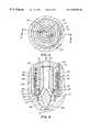
- FIG. 1is a sectional view of a portion of a multi-cavity injection molding apparatus or system having a heated nozzle with a nozzle seal screwed onto the outside of its front end,
- FIG. 2is an exploded isometric view showing the front end of the nozzle with the mounting sleeve in place and the nozzle seal seen in FIG. 1,
- FIG. 3is a bottom view of the front end of a nozzle having a nozzle seal according to another embodiment of the invention.
- FIG. 4is a sectional view along line 4 — 4 in FIG. 3, and
- FIG. 5is a sectional view of the front end of a nozzle having a nozzle seal according to a further embodiment of the invention.
- FIGS. 1 and 2show a portion of a multi-cavity injection molding system or apparatus having a melt distribution manifold 10 interconnecting several heated nozzles 12 .
- Each nozzle 12is seated in a well 14 having a generally cylindrical wall 16 in a mold 18 . While the mold 18 usually has a greater number of plates depending upon the application, in this case, only a back plate 20 , a manifold plate 22 , a cavity insert 26 seated in a cavity plate 28 , and a core plate 30 are shown for ease of illustration.
- the melt distribution manifold 10is heated by an integral electrical heating element 32 and the mold 18 is cooled by pumping cooling water through cooling conduits 34 .
- the melt distribution manifold 10is mounted between the manifold plate 22 and the back plate 20 by a central locating ring 36 and a number of insulative spacers 38 to provide an insulative air space 40 between the heated manifold 10 and the surrounding cooled mold 18 .
- each nozzle 12has an integral electrical heating element 48 with a terminal 50 and a helical portion 52 extending around a central melt bore 54 .
- An outer collar 56 at the rear end 42 of each nozzle 12has a forwardly extending flange portion 58 which sits on a circular seat 60 in the mold 18 to locate the rear end 42 of the heated nozzle 12 and provide an insulative air space 62 between the heated nozzle 12 and the surrounding cooled mold 18 .
- a melt passage 64extends from a central inlet 66 in a cylindrical inlet portion 68 of the melt distribution manifold 10 and branches outwardly in the melt distribution manifold 10 to convey melt to the central melt bore 54 in each heated nozzle 12 .
- the heated nozzle 12has a tip insert 70 with a pointed front tip 72 shrunk fit into a cylindrical seat 74 in the front end 76 of the heated nozzle 12 .
- the heated nozzle 12is made of steel and the tip insert 70 is made of a material such as beryllium copper or tungsten carbide copper having a combination of thermal conductivity and wear and corrosion resistance suitable for the material being molded.
- the tip insert 70has a rear end 78 and a conical outer surface 80 extending forwardly to the tip 72 .
- melt bore 82with a slightly tapered central rear portion 84 which splits into two front portions 86 extending diagonally outward from the rear portion 84 to the outer conical surface 80 .
- the rear portion 84 of the melt bore 82extends through the tip insert 70 from an inlet 87 at the rear end 78 in alignment with the central melt bore 54 extending through the nozzle 12 .
- the melt from the melt passage 64flows through the melt bore 54 in each nozzle 12 and the melt bore 82 in the tip insert 70 into a space 88 around the conical surface 80 of the tip insert 70 and through the gate 90 into the cavity 92 .
- the two front portions 86are slightly offset from the center of the tip insert 70 to impart a swirling motion to the melt flowing through the gate 90 .
- two diagonal front portions 86 of the melt bore 82are shown, in other embodiments there can be only one or more than two.
- the heated nozzle 12has a front portion 94 adjacent its front end 76 with a cylindrical outer surface 96 .
- a mounting sleeve 98 having a larger diameter rear portion 100 and a front portion 102 with a threaded outer surface 104 according to the inventionextends around the front portion 94 of the nozzle 12 .
- the mounting sleeve 98is made of hot work tool steel and is integrally brazed in place at the same time the electrical heating element 48 is integrally brazed in place in a vacuum furnace.
- the mounting sleeve 98provides the heated nozzle 12 with additional bursting or hoop strength and a larger heat sink.
- the rear portion 100 of the mounting sleevehas a rearwardly open hole 106 therein into which a thermocouple element 108 extends to control the operating temperature.
- a hollow removable nozzle seal 110is mounted on the front end 76 of the nozzle 12 .
- the nozzle seal 110is hollow and is made of a suitable wear and corrosion resistant material such as stainless or H-13 tool steel.
- the nozzle seal 110has a central nut portion 112 with an outer surface 114 with an even number of outer facets 116 such as the double hex shown to be engaged by a wrench (not shown) to tighten and remove the nozzle seal 110 .
- the central nut portion 112has an insulation groove 117 to reduce heat loss to the cooled mold 18 .
- the nozzle seal 110can be made to be engaged by a different type of tool.
- the hollow nozzle seal 110has a cylindrical retaining portion 118 extending rearwardly from the central nut portion 112 .
- the retaining rear portion 118has a threaded inner surface 120 which fits around the threaded outer surface 104 of the mounting sleeve 98 .
- the nozzle seal 110also has a cylindrical sealing and alignment flange portion 122 extending forwardly from the central nut portion 112 .
- the forwardly extending sealing and alignment flange portion 122is made to fit into a cylindrical portion 124 of the well 14 in the mold 18 extending adjacent the gate 90 to align the front tip 72 of the tip insert 70 with the gate 90 and to provide a seal to prevent leakage of the melt into the insulative air space 62 between the heated nozzle 12 and the surrounding cooled mold 18 .
- the central nut portion 112 of the nozzle seal 110has an opening 126 therethrough with a tapered inner surface 128 .
- the tapered inner surface 128 of the opening 126is made to fit with very close tolerances around a matching outer surface 130 extending around the tip insert 70 which is tapered inwardly towards the front to retain the tip insert 70 in place in the cylindrical seat 74 in the heated nozzle 12 and to very accurately locate the front end 76 of the heated nozzle 12 with the front tip 72 aligned with the gate 90 .
- the surfaces 128 , 130can have straight and shoulder portions to retain the tip insert 70 in place and to locate the front end of the heated nozzle 12 .
- the threaded rear portion 118retains the nozzle seal 110 , it is the tapered surfaces 128 , 130 and the sealing and alignment flange portion 122 which locate the front end 76 of the heated nozzle 12 with the front tip 72 of the tip insert 70 aligned with the gate 90 . As these surfaces are not threaded, the location is much more accurate than relying on threaded surfaces.
- Another advantage of the nozzle seal 110 screwing onto the outside of the heated nozzle 12 rather than the inside,is that it allows the tip insert 70 which is made of a more conductive material to be larger. This increased size provides a larger heat sink and brings the more conductive material into closer proximity to the electrical heating element 48 and provides increased and more uniform heat to the front tip 72 which reduces cycle time. Furthermore, the nozzle seal 110 itself as well as the mounting sleeve 98 being in tension provides additional bursting or hoop strength.
- the apparatusis first installed as shown in FIG. 1 and described above. Electrical power is then applied to the heating element 32 in the melt distribution manifold 10 and to the heating elements 48 in each of the nozzles 12 to heat them to a predetermined operating temperature. Pressurized melt is applied from a molding machine (not shown) to the central inlet 66 of the melt passage 64 to provide hot tip gating according to a predetermined injection cycle. The melt flows through the melt distribution manifold 10 , the melt bores 54 , 82 in the heated nozzles 12 and the tip inserts 70 , and through the gates 90 into the cavities 92 .
- the injection pressureis released and the melt conveying system is decompressed to avoid stringing through the open gates 90 .
- the mold 18is then opened to eject the molded products. After ejection, the mold 18 is closed and the cycle is repeated continuously with the cycle time dependent upon the size of the cavities 92 and the type of material being molded.
- FIGS. 3 and 4show a nozzle seal 110 according to another embodiment of the invention.
- This embodimentis the same as the embodiment described above except that the inner surface 128 of the opening 126 through the central nut portion 112 of the nozzle seal 110 and the matching outer surface 130 of the tip insert 70 are straight rather than tapered.
- the tip insert 70is integrally brazed into place in the cylindrical seat 74 in the front end 76 of the heated nozzle 12 and the taper is not required to retain it in place.
- FIG. 5shows a nozzle seal 132 (which is also a gate insert) according to another embodiment of the invention having a valve pin 133 for valve gating.
- the nozzle seal 132similarly has the hollow cylindrical retaining portion 118 extending rearwardly from a central nut portion 134 .
- the rearwardly extending retaining portion 118also has the threaded inner surface 120 which screws onto the threaded outer surface 104 of the mounting sleeve 98 which is brazed in place around the front portion 94 of the heated nozzle 12 as described above.
- the central nut portion 134 and a sealing and locating portion 136 extending forwardly therefromhave a melt bore 138 extending therethrough in alignment with the melt bore 54 in the heated nozzle 12 and leading to a gate 140 at the front end 142 of the nozzle seal 132 .
- the sealing and locating portion 136 of the nozzle seal 132has a cylindrical outer surface 144 which is made to fit into a cylindrical opening 148 in the mold 18 extending to the cavity 92 to locate the front end 76 of the heated nozzle 12 and prevent leakage of melt into the insulative air space 62 between the heated nozzle 12 and the surrounding cooled mold 18 .
- the central nut portion 134also has an outer surface 114 with facets 116 to be engaged by a wrench. The use of this embodiment is the same as described above.
Landscapes
- Engineering & Computer Science (AREA)
- Manufacturing & Machinery (AREA)
- Mechanical Engineering (AREA)
- Moulds For Moulding Plastics Or The Like (AREA)
- Injection Moulding Of Plastics Or The Like (AREA)
Abstract
Description
Claims (16)
Priority Applications (1)
| Application Number | Priority Date | Filing Date | Title |
|---|---|---|---|
| PCT/CA2000/000142WO2000048814A1 (en) | 1999-02-16 | 2000-02-15 | Injection molding apparatus with removable nozzle seal |
Applications Claiming Priority (2)
| Application Number | Priority Date | Filing Date | Title |
|---|---|---|---|
| CA2262175 | 1999-02-16 | ||
| CA002262175ACA2262175C (en) | 1999-02-16 | 1999-02-16 | Injection molding apparatus with removable nozzle seal |
Publications (1)
| Publication Number | Publication Date |
|---|---|
| US6302680B1true US6302680B1 (en) | 2001-10-16 |
Family
ID=4163302
Family Applications (1)
| Application Number | Title | Priority Date | Filing Date |
|---|---|---|---|
| US09/261,466Expired - LifetimeUS6302680B1 (en) | 1999-02-16 | 1999-02-24 | Injection molding apparatus with removable nozzle seal |
Country Status (13)
| Country | Link |
|---|---|
| US (1) | US6302680B1 (en) |
| EP (1) | EP1152880B1 (en) |
| JP (1) | JP2002537142A (en) |
| KR (1) | KR20010102197A (en) |
| CN (1) | CN1144665C (en) |
| AT (1) | ATE238896T1 (en) |
| AU (1) | AU2530600A (en) |
| BR (1) | BR0010039A (en) |
| CA (1) | CA2262175C (en) |
| DE (1) | DE60002440T2 (en) |
| ES (1) | ES2197857T3 (en) |
| MX (1) | MXPA01008317A (en) |
| WO (1) | WO2000048814A1 (en) |
Cited By (28)
| Publication number | Priority date | Publication date | Assignee | Title |
|---|---|---|---|---|
| US20030091684A1 (en)* | 2001-11-14 | 2003-05-15 | Hefner Elastomere-Technik Gmbh | Injection nozzle for gum elastic, rubber and polysiloxanes |
| EP1321274A1 (en)* | 2001-12-21 | 2003-06-25 | INCOS S.p.A | Injection nozzle for plastic injection moulding equipment |
| US20030143302A1 (en)* | 2002-01-25 | 2003-07-31 | Hotset Heizpatronen U. Zubehor Gmbh | Mounting sleeve for nozzle heater |
| US6609902B1 (en) | 2002-11-12 | 2003-08-26 | Husky Injection Molding Systems Ltd. | Injection molding nozzle |
| US20040076708A1 (en)* | 2002-10-16 | 2004-04-22 | Lefebure Brian R. | Injection molding nozzle |
| US20040224046A1 (en)* | 2003-05-08 | 2004-11-11 | Mold-Masters, Inc. | Transfer seal for a removable nozzle tip of an injection molding apparatus |
| US20040228942A1 (en)* | 2003-05-08 | 2004-11-18 | Mold-Masters Limited | Hot runner nozzle with removable tip and tip retainer |
| US6960072B1 (en)* | 2002-06-21 | 2005-11-01 | Polyshot Corporation | Hot sprue bushing |
| US20050271766A1 (en)* | 2004-06-02 | 2005-12-08 | Mold-Masters Limited. | Injection molding nozzle having an annular flow tip |
| US20060018993A1 (en)* | 2004-06-02 | 2006-01-26 | Mold-Masters Limited | Valve-gated injection moding nozzle having an annular flow |
| DE102004038056B3 (en)* | 2004-08-05 | 2006-03-09 | Otto Männer Innovation GmbH | hot runner nozzle |
| US20070141195A1 (en)* | 2005-12-20 | 2007-06-21 | Jincheng Chen | Injection molding apparatus having swiveling nozzles |
| US20070172538A1 (en)* | 2006-01-26 | 2007-07-26 | Adas James O | Apparatus for injection molding |
| USRE39935E1 (en)* | 1999-02-26 | 2007-12-04 | Mold-Masters Limited | Multi-cavity injection molding apparatus splitting melt near nozzle front |
| US20080026227A1 (en)* | 2003-02-04 | 2008-01-31 | Canon Kabushiki Kaisha | Method of manufacturing a resin molding |
| US20080141333A1 (en)* | 2006-12-12 | 2008-06-12 | Boeing Company, A Corporation Of Delaware | Method and system for object-based multi-level security in a service oriented architecture |
| US20080180117A1 (en)* | 2007-01-29 | 2008-07-31 | Electro Scientific Industries, Inc. | Adjustable Force Electrical Contactor |
| US20080274229A1 (en)* | 2007-05-03 | 2008-11-06 | Husky Injection Molding Systems Ltd. | Nanocrystalline Hot Runner Nozzle |
| USRE40584E1 (en) | 2001-01-23 | 2008-11-25 | Mold-Masters (2007) Limited | Nozzle end for multiple tipped injection molding nozzle |
| US7544056B2 (en) | 2004-06-02 | 2009-06-09 | Mold-Masters (2007) Limited | Valve-gated injection molding nozzle having an annular flow |
| US20090194903A1 (en)* | 2008-01-31 | 2009-08-06 | Husky Injection Molding Systems Ltd. | Non-stringing hot tip |
| US7771189B2 (en) | 2008-03-03 | 2010-08-10 | R&D Tool & Engineering Co. | Injection molding apparatus with replaceable gate insert |
| US7780434B2 (en) | 2001-10-03 | 2010-08-24 | Mold-Masters (2007) Limited | Nozzle for an injection molding apparatus |
| EP2639036A1 (en)* | 2012-03-16 | 2013-09-18 | Mold-Masters (2007) Limited | Edge-gated injection molding apparatus |
| US20140037783A1 (en)* | 2011-04-26 | 2014-02-06 | Husky Injection Molding Systems Ltd. | Mold-Tool System Including Nozzle-Tip Assembly Configured for Reduced Axial Tilting |
| WO2014028309A3 (en)* | 2012-08-16 | 2014-04-10 | Husky Injection Molding Systems Ltd. | Gate- aligned nozzle stack for injection-molding apparatus |
| US20140319126A1 (en)* | 2013-04-29 | 2014-10-30 | Foxnum Technology Co., Ltd. | Nozzle of injection machine and heating apparatus of the nozzle |
| US20140377401A1 (en)* | 2012-09-27 | 2014-12-25 | Olympus Corporation | Hot-runner molding apparatus and hot-runner nozzle |
Families Citing this family (23)
| Publication number | Priority date | Publication date | Assignee | Title |
|---|---|---|---|---|
| CA2286953A1 (en)* | 1999-10-18 | 2001-04-18 | Helen Zhuang | Injection nozzle system |
| US6769901B2 (en) | 2000-04-12 | 2004-08-03 | Mold-Masters Limited | Injection nozzle system for an injection molding machine |
| ITTO20010017U1 (en)* | 2001-02-07 | 2001-05-08 | Piero Enrietti | INJECTION NOZZLE FOR MOLDING OF PLASTIC MATERIALS. |
| CA2358187A1 (en) | 2001-10-03 | 2003-04-03 | Mold-Masters Limited | Nozzle seal |
| US6962492B2 (en) | 2001-10-05 | 2005-11-08 | Mold-Masters Limited | Gap seal between nozzle components |
| US7128566B2 (en) | 2002-02-21 | 2006-10-31 | Mold-Masters Limited | Valve pin guiding tip for a nozzle |
| CA2485039C (en) | 2002-04-12 | 2011-06-07 | Jobst Ulrich Gellert | Mold gate insert with a thermal barrier |
| CN100448646C (en) | 2002-07-30 | 2009-01-07 | 标准模具(2007)有限公司 | Valve pin guidance and alignment system for hot runner in injection molding apparatus |
| DE10354456B4 (en) | 2002-11-21 | 2016-10-13 | Mold-Masters (2007) Limited | Nozzle having a tip, a part surrounding the tip and a positioning part and injection molding device with the nozzle |
| CA2452112A1 (en) | 2002-12-09 | 2004-06-09 | Mold-Masters Limited | Nozzle tip and seal |
| DE102004009799B4 (en)* | 2004-02-28 | 2006-03-23 | Incoe International, Inc. | Tool insert for the cutting of a hot runner nozzle for an injection molding machine |
| US7217120B2 (en) | 2004-06-16 | 2007-05-15 | V-Tek Molding Technologies Inc. | Hot runner nozzle |
| DE102006026580A1 (en)* | 2006-06-08 | 2007-12-13 | Günther Heisskanaltechnik Gmbh | Injection molding nozzle, in particular hot runner nozzle, for placement in an injection mold |
| DE102006049073A1 (en)* | 2006-10-13 | 2008-04-17 | Hasco Hasenclever Gmbh + Co Kg | Injection nozzle for guiding melt mass in a plastic injection mold |
| FR2910836B1 (en)* | 2006-12-27 | 2012-06-15 | Curtil Sa | INJECTION NOZZLE OF FUSION PLASTIC MATERIAL |
| US7874833B2 (en)* | 2009-05-03 | 2011-01-25 | Mold-Masters (2007) Limited | Injection molding runner apparatus having pressure seal |
| CN103205819B (en)* | 2013-04-08 | 2015-04-08 | 北京中纺优丝特种纤维科技有限公司 | Detachable spinning manifold heated by biphenyl steam which is heating medium |
| DE102016203995A1 (en)* | 2016-03-10 | 2017-09-14 | Otto Männer Innovation GmbH | Hot runner system and associated nozzle heaters |
| CN109304469A (en)* | 2017-07-28 | 2019-02-05 | 昆山汉鼎精密金属有限公司 | Nozzle structure |
| DE102017217066A1 (en)* | 2017-09-26 | 2019-03-28 | Conti Temic Microelectronic Gmbh | Sealing ring with a sensor, fluid connection, cooling circuit and method for producing a seal |
| CN109702967A (en)* | 2019-02-15 | 2019-05-03 | 贝普医疗科技有限公司 | A heat conduction structure for hot runner injection molding |
| CN110978412A (en)* | 2020-01-08 | 2020-04-10 | 成都市联余精密机械有限公司 | A wear-resistant plastic injection structure and its installation process |
| KR102742728B1 (en)* | 2022-04-21 | 2024-12-16 | 주식회사 유도 | Under Cut Seal Cap for PET Preform Hot runner |
Citations (14)
| Publication number | Priority date | Publication date | Assignee | Title |
|---|---|---|---|---|
| US3935972A (en) | 1973-12-28 | 1976-02-03 | Fuji Plastic Co., Ltd. | Pressure actuated nozzle valve for injection molding units |
| US4010903A (en) | 1974-06-27 | 1977-03-08 | Torazo Saito | Nozzle for injection molding of thermoplastics |
| US4266723A (en) | 1979-11-02 | 1981-05-12 | Incoe Corporation | Nozzle for injection molding machines |
| NL8004819A (en) | 1980-08-26 | 1982-04-01 | Wavin Bv | Nozzle assembly for plastic extrusion press - has heated duct with separate and interchangeable component contg. nozzle orifice |
| US4793795A (en) | 1987-10-16 | 1988-12-27 | Mold-Masters Limited | Injection molding system having clamped rotatable nozzles and method |
| US5028227A (en) | 1988-10-31 | 1991-07-02 | Mold-Masters Limited | Injection molding nozzle with replaceable gate insert |
| US5208052A (en) | 1991-11-18 | 1993-05-04 | Husky Injection Molding Systems Ltd. | Hot runner nozzle assembly |
| US5299928A (en) | 1993-07-26 | 1994-04-05 | Gellert Jobst U | Two-piece injection molding nozzle seal |
| EP0854027A1 (en) | 1997-01-21 | 1998-07-22 | Husky Injection Molding Systems Ltd. | Insulated modular injection nozzle assembly |
| US5795599A (en) | 1996-10-09 | 1998-08-18 | Gellert; Jobst Ulrich | Injection molding nozzle guide and sealing ring |
| US5849343A (en) | 1997-04-25 | 1998-12-15 | Mold-Masters Limited | Injection molding apparatus with a one-piece gate insert locating a cylindrical valve member |
| US5871786A (en) | 1997-04-04 | 1999-02-16 | Kona Corporation | Tip heated hot runner nozzle |
| US5895669A (en) | 1997-06-13 | 1999-04-20 | Incoe Corporation | Injection molding shut-off bushing with separate material flow path |
| US6009616A (en) | 1998-10-16 | 2000-01-04 | Gellert; Jobst Ulrich | Method of making an injection molding nozzle with tip insert |
- 1999
- 1999-02-16CACA002262175Apatent/CA2262175C/ennot_activeExpired - Fee Related
- 1999-02-24USUS09/261,466patent/US6302680B1/ennot_activeExpired - Lifetime
- 2000
- 2000-02-15CNCNB008043647Apatent/CN1144665C/ennot_activeExpired - Fee Related
- 2000-02-15BRBR0010039-0Apatent/BR0010039A/ennot_activeApplication Discontinuation
- 2000-02-15DEDE60002440Tpatent/DE60002440T2/ennot_activeExpired - Lifetime
- 2000-02-15WOPCT/CA2000/000142patent/WO2000048814A1/ennot_activeApplication Discontinuation
- 2000-02-15MXMXPA01008317Apatent/MXPA01008317A/enactiveIP Right Grant
- 2000-02-15EPEP00903472Apatent/EP1152880B1/ennot_activeExpired - Lifetime
- 2000-02-15ATAT00903472Tpatent/ATE238896T1/ennot_activeIP Right Cessation
- 2000-02-15JPJP2000599579Apatent/JP2002537142A/enactivePending
- 2000-02-15KRKR1020017010417Apatent/KR20010102197A/ennot_activeWithdrawn
- 2000-02-15ESES00903472Tpatent/ES2197857T3/ennot_activeExpired - Lifetime
- 2000-02-15AUAU25306/00Apatent/AU2530600A/ennot_activeAbandoned
Patent Citations (15)
| Publication number | Priority date | Publication date | Assignee | Title |
|---|---|---|---|---|
| US3935972A (en) | 1973-12-28 | 1976-02-03 | Fuji Plastic Co., Ltd. | Pressure actuated nozzle valve for injection molding units |
| US4010903A (en) | 1974-06-27 | 1977-03-08 | Torazo Saito | Nozzle for injection molding of thermoplastics |
| US4266723A (en) | 1979-11-02 | 1981-05-12 | Incoe Corporation | Nozzle for injection molding machines |
| NL8004819A (en) | 1980-08-26 | 1982-04-01 | Wavin Bv | Nozzle assembly for plastic extrusion press - has heated duct with separate and interchangeable component contg. nozzle orifice |
| US4793795A (en) | 1987-10-16 | 1988-12-27 | Mold-Masters Limited | Injection molding system having clamped rotatable nozzles and method |
| US5028227A (en) | 1988-10-31 | 1991-07-02 | Mold-Masters Limited | Injection molding nozzle with replaceable gate insert |
| US5208052A (en) | 1991-11-18 | 1993-05-04 | Husky Injection Molding Systems Ltd. | Hot runner nozzle assembly |
| US5299928A (en) | 1993-07-26 | 1994-04-05 | Gellert Jobst U | Two-piece injection molding nozzle seal |
| US5795599A (en) | 1996-10-09 | 1998-08-18 | Gellert; Jobst Ulrich | Injection molding nozzle guide and sealing ring |
| EP0854027A1 (en) | 1997-01-21 | 1998-07-22 | Husky Injection Molding Systems Ltd. | Insulated modular injection nozzle assembly |
| US5879727A (en) | 1997-01-21 | 1999-03-09 | Husky Injection Molding Systems, Ltd. | Insulated modular injection nozzle system |
| US5871786A (en) | 1997-04-04 | 1999-02-16 | Kona Corporation | Tip heated hot runner nozzle |
| US5849343A (en) | 1997-04-25 | 1998-12-15 | Mold-Masters Limited | Injection molding apparatus with a one-piece gate insert locating a cylindrical valve member |
| US5895669A (en) | 1997-06-13 | 1999-04-20 | Incoe Corporation | Injection molding shut-off bushing with separate material flow path |
| US6009616A (en) | 1998-10-16 | 2000-01-04 | Gellert; Jobst Ulrich | Method of making an injection molding nozzle with tip insert |
Cited By (58)
| Publication number | Priority date | Publication date | Assignee | Title |
|---|---|---|---|---|
| USRE39935E1 (en)* | 1999-02-26 | 2007-12-04 | Mold-Masters Limited | Multi-cavity injection molding apparatus splitting melt near nozzle front |
| USRE40584E1 (en) | 2001-01-23 | 2008-11-25 | Mold-Masters (2007) Limited | Nozzle end for multiple tipped injection molding nozzle |
| US7780434B2 (en) | 2001-10-03 | 2010-08-24 | Mold-Masters (2007) Limited | Nozzle for an injection molding apparatus |
| US7891969B2 (en) | 2001-10-03 | 2011-02-22 | Mold-Masters (2007) Limited | Injection molding nozzle |
| US20030091684A1 (en)* | 2001-11-14 | 2003-05-15 | Hefner Elastomere-Technik Gmbh | Injection nozzle for gum elastic, rubber and polysiloxanes |
| US6960073B2 (en) | 2001-12-21 | 2005-11-01 | Incos S.P.A. | Injection nozzle for plastic injection moulding equipment |
| US20030118688A1 (en)* | 2001-12-21 | 2003-06-26 | Incos S.P.A. | Injection nozzle for plastic injection moulding equipment |
| EP1321274A1 (en)* | 2001-12-21 | 2003-06-25 | INCOS S.p.A | Injection nozzle for plastic injection moulding equipment |
| US6832909B2 (en) | 2001-12-21 | 2004-12-21 | Incos S.P.A. | Injection nozzle for plastic injection moulding equipment |
| US20050069605A1 (en)* | 2001-12-21 | 2005-03-31 | Incos S.P.A. | Injection nozzle for plastic injection moulding equipment |
| US20030143302A1 (en)* | 2002-01-25 | 2003-07-31 | Hotset Heizpatronen U. Zubehor Gmbh | Mounting sleeve for nozzle heater |
| US6872068B2 (en)* | 2002-01-25 | 2005-03-29 | Hotset Heizpatronen U. Zubehor Gmbh | Mounting sleeve for nozzle heater |
| US6960072B1 (en)* | 2002-06-21 | 2005-11-01 | Polyshot Corporation | Hot sprue bushing |
| US20040076708A1 (en)* | 2002-10-16 | 2004-04-22 | Lefebure Brian R. | Injection molding nozzle |
| WO2004035291A1 (en)* | 2002-10-16 | 2004-04-29 | R & D Tool & Engineering Co. | Injection molding nozzle |
| US6726467B1 (en)* | 2002-10-16 | 2004-04-27 | R&D Tool & Engineering Co. | Injection molding nozzle |
| US6609902B1 (en) | 2002-11-12 | 2003-08-26 | Husky Injection Molding Systems Ltd. | Injection molding nozzle |
| US20090041973A1 (en)* | 2003-02-04 | 2009-02-12 | Canon Kabushiki Kaisha | Resin molding and its manufacturing method and resin injecting apparatus used for the same |
| US7467938B2 (en)* | 2003-02-04 | 2008-12-23 | Canon Kabushiki Kaisha | Resin injecting apparatus with a cooling passage |
| US7744978B2 (en) | 2003-02-04 | 2010-06-29 | Canon Kabushiki Kaisha | Resin molding |
| US20080026227A1 (en)* | 2003-02-04 | 2008-01-31 | Canon Kabushiki Kaisha | Method of manufacturing a resin molding |
| US7131832B2 (en) | 2003-05-08 | 2006-11-07 | Mold-Masters Limited | Transfer seal for a removable nozzle tip of an injection molding apparatus |
| US7143496B2 (en) | 2003-05-08 | 2006-12-05 | Mold-Masters Limited | Hot runner nozzle with removable tip and tip retainer |
| US20040224046A1 (en)* | 2003-05-08 | 2004-11-11 | Mold-Masters, Inc. | Transfer seal for a removable nozzle tip of an injection molding apparatus |
| US20040228942A1 (en)* | 2003-05-08 | 2004-11-18 | Mold-Masters Limited | Hot runner nozzle with removable tip and tip retainer |
| US20060018993A1 (en)* | 2004-06-02 | 2006-01-26 | Mold-Masters Limited | Valve-gated injection moding nozzle having an annular flow |
| US7364425B2 (en) | 2004-06-02 | 2008-04-29 | Mold-Masters (2007) Limited | Valve-gated injection molding nozzle having an annular flow |
| US20080113062A1 (en)* | 2004-06-02 | 2008-05-15 | Mold-Masters (2007) Limited | Injection Molding Nozzle Having An Annular Flow Tip |
| US7611349B2 (en) | 2004-06-02 | 2009-11-03 | Mold-Masters (2007) Limited | Injection molding nozzle having an annular flow tip |
| US20050271766A1 (en)* | 2004-06-02 | 2005-12-08 | Mold-Masters Limited. | Injection molding nozzle having an annular flow tip |
| US7344372B2 (en)* | 2004-06-02 | 2008-03-18 | Mold-Masters (2007) Limited | Injection molding nozzle having an annular flow tip |
| US7544056B2 (en) | 2004-06-02 | 2009-06-09 | Mold-Masters (2007) Limited | Valve-gated injection molding nozzle having an annular flow |
| DE102004038056B3 (en)* | 2004-08-05 | 2006-03-09 | Otto Männer Innovation GmbH | hot runner nozzle |
| US20070141195A1 (en)* | 2005-12-20 | 2007-06-21 | Jincheng Chen | Injection molding apparatus having swiveling nozzles |
| US7704069B2 (en) | 2005-12-20 | 2010-04-27 | R&D Tool & Engineering Co. | Injection molding apparatus having swiveling nozzles |
| US7361010B2 (en) | 2006-01-26 | 2008-04-22 | D-M-E Company | Apparatus for injection molding |
| US20070172538A1 (en)* | 2006-01-26 | 2007-07-26 | Adas James O | Apparatus for injection molding |
| US20080141333A1 (en)* | 2006-12-12 | 2008-06-12 | Boeing Company, A Corporation Of Delaware | Method and system for object-based multi-level security in a service oriented architecture |
| US7839138B2 (en)* | 2007-01-29 | 2010-11-23 | Electro Scientific Industries, Inc. | Adjustable force electrical contactor |
| US20080180117A1 (en)* | 2007-01-29 | 2008-07-31 | Electro Scientific Industries, Inc. | Adjustable Force Electrical Contactor |
| DE112008001075B4 (en)* | 2007-05-03 | 2012-12-13 | Husky Injection Molding Systems Ltd. | Nanocrystalline hot runner nozzle |
| DE112008001075T5 (en) | 2007-05-03 | 2010-06-10 | Husky Injection Molding Systems Ltd., Bolton | Nanocrystalline hot-runner nozzle |
| US7494336B2 (en) | 2007-05-03 | 2009-02-24 | Husky Injection Molding Systems Ltd. | Nanocrystalline hot runner nozzle and nozzle tip |
| US20080274229A1 (en)* | 2007-05-03 | 2008-11-06 | Husky Injection Molding Systems Ltd. | Nanocrystalline Hot Runner Nozzle |
| USRE43424E1 (en)* | 2007-05-03 | 2012-05-29 | Husky Injection Molding Systems Ltd. | Nanocrystalline hot runner nozzle tip |
| US7695271B2 (en) | 2008-01-31 | 2010-04-13 | Husky Injection Molding Systems Ltd. | Non-stringing nozzle tip |
| US20090194903A1 (en)* | 2008-01-31 | 2009-08-06 | Husky Injection Molding Systems Ltd. | Non-stringing hot tip |
| WO2009097257A1 (en)* | 2008-01-31 | 2009-08-06 | Husky Injection Molding Systems Ltd | Non-stringing hot tip |
| US7771189B2 (en) | 2008-03-03 | 2010-08-10 | R&D Tool & Engineering Co. | Injection molding apparatus with replaceable gate insert |
| US20140037783A1 (en)* | 2011-04-26 | 2014-02-06 | Husky Injection Molding Systems Ltd. | Mold-Tool System Including Nozzle-Tip Assembly Configured for Reduced Axial Tilting |
| US9266270B2 (en)* | 2011-04-26 | 2016-02-23 | Husky Injection Molding Systems, Ltd | Mold-tool system including nozzle-tip assembly configured for reduced axial tilting |
| EP2639036A1 (en)* | 2012-03-16 | 2013-09-18 | Mold-Masters (2007) Limited | Edge-gated injection molding apparatus |
| US8899964B2 (en) | 2012-03-16 | 2014-12-02 | Mold-Masters (2007) Limited | Edge-gated injection molding apparatus |
| WO2014028309A3 (en)* | 2012-08-16 | 2014-04-10 | Husky Injection Molding Systems Ltd. | Gate- aligned nozzle stack for injection-molding apparatus |
| US20140377401A1 (en)* | 2012-09-27 | 2014-12-25 | Olympus Corporation | Hot-runner molding apparatus and hot-runner nozzle |
| US9610722B2 (en)* | 2012-09-27 | 2017-04-04 | Olympus Corporation | Hot-runner molding apparatus and hot-runner nozzle |
| US20140319126A1 (en)* | 2013-04-29 | 2014-10-30 | Foxnum Technology Co., Ltd. | Nozzle of injection machine and heating apparatus of the nozzle |
| US9440387B2 (en)* | 2013-04-29 | 2016-09-13 | Foxnum Technology Co., Ltd. | Nozzle of injection machine and heating apparatus of the nozzle |
Also Published As
| Publication number | Publication date |
|---|---|
| KR20010102197A (en) | 2001-11-15 |
| CN1342113A (en) | 2002-03-27 |
| ES2197857T3 (en) | 2004-01-16 |
| EP1152880A1 (en) | 2001-11-14 |
| CN1144665C (en) | 2004-04-07 |
| DE60002440D1 (en) | 2003-06-05 |
| EP1152880B1 (en) | 2003-05-02 |
| WO2000048814A1 (en) | 2000-08-24 |
| DE60002440T2 (en) | 2003-11-20 |
| MXPA01008317A (en) | 2003-06-06 |
| ATE238896T1 (en) | 2003-05-15 |
| CA2262175C (en) | 2008-02-12 |
| BR0010039A (en) | 2002-03-26 |
| CA2262175A1 (en) | 2000-08-16 |
| AU2530600A (en) | 2000-09-04 |
| JP2002537142A (en) | 2002-11-05 |
Similar Documents
| Publication | Publication Date | Title |
|---|---|---|
| US6302680B1 (en) | Injection molding apparatus with removable nozzle seal | |
| US6176700B1 (en) | Injection molding cooled cavity insert | |
| US5443381A (en) | Injection molding one-piece insert having cooling chamber with radial rib portions | |
| US4981431A (en) | Injection molding system with flanged insulating gate seal | |
| US5299928A (en) | Two-piece injection molding nozzle seal | |
| US5849343A (en) | Injection molding apparatus with a one-piece gate insert locating a cylindrical valve member | |
| US5494433A (en) | Injection molding hot tip side gate seal having a circumferential rim | |
| US5955121A (en) | Injection molding apparatus with insert secured through the manifold to a nozzle | |
| CA2572585C (en) | Injection molding nozzle with two-piece seal | |
| EP0523549A2 (en) | Injection molding manifold with removable inserts | |
| US6447283B1 (en) | Injection molding heater with melt bore therethrough | |
| EP0743158B1 (en) | Injection molding hot tip side gate seal with circumferential rim | |
| US6162044A (en) | Multi-cavity injection molding apparatus splitting melt near nozzle front | |
| US5536165A (en) | Injection molding apparatus with nozzle advanceable to mount side gate seals | |
| US5118280A (en) | Injection molding apparatus with integral cooling in a forward portion of the nozzle | |
| CA2082700A1 (en) | Injection molding torpedo with diagonal melt bore | |
| US6203310B1 (en) | Injection molding apparatus having mold cores with reverse taper | |
| US5980236A (en) | Injection molding apparatus having nozzles with elongated mounting flanges | |
| US5122050A (en) | Injection molding probe with a longitudinal thermocouple bore and off center heating element | |
| EP0633118B1 (en) | Two-piece injection molding nozzle seal | |
| US4795338A (en) | Mounting for injection molding nozzle | |
| EP0743157A1 (en) | Injection molding apparatus with nozzle advanceable to mount side gate seals | |
| US7370417B2 (en) | Method of installing a mold gate insert in an injection molding apparatus | |
| USRE39935E1 (en) | Multi-cavity injection molding apparatus splitting melt near nozzle front | |
| CA2078890A1 (en) | Injection molding nozzle with thermocouple receiving torpedo |
Legal Events
| Date | Code | Title | Description |
|---|---|---|---|
| AS | Assignment | Owner name:MOLD-MASTERS LIMITED, CANADA Free format text:ASSIGNMENT OF ASSIGNORS INTEREST;ASSIGNORS:GELLERT, JOBST ULRICH;NAKANISHI, ITSUTO;REEL/FRAME:009812/0409 Effective date:19990222 | |
| STCF | Information on status: patent grant | Free format text:PATENTED CASE | |
| FEPP | Fee payment procedure | Free format text:PAYOR NUMBER ASSIGNED (ORIGINAL EVENT CODE: ASPN); ENTITY STATUS OF PATENT OWNER: LARGE ENTITY | |
| FPAY | Fee payment | Year of fee payment:4 | |
| AS | Assignment | Owner name:4437667 CANADA INC., CANADA Free format text:GENERAL ASSIGNMENT OF PATENTS;ASSIGNOR:MOLD MASTERS LIMITED;REEL/FRAME:019955/0213 Effective date:20071011 Owner name:4437667 CANADA INC.,CANADA Free format text:GENERAL ASSIGNMENT OF PATENTS;ASSIGNOR:MOLD MASTERS LIMITED;REEL/FRAME:019955/0213 Effective date:20071011 | |
| AS | Assignment | Owner name:SOCIETE GENERALE, NEW YORK Free format text:SECURITY AGREEMENT;ASSIGNOR:4437667 CANADA INC.;REEL/FRAME:020174/0241 Effective date:20071011 Owner name:SOCIETE GENERALE,NEW YORK Free format text:SECURITY AGREEMENT;ASSIGNOR:4437667 CANADA INC.;REEL/FRAME:020174/0241 Effective date:20071011 | |
| FPAY | Fee payment | Year of fee payment:8 | |
| AS | Assignment | Owner name:MOLD-MASTERS (2007) LIMITED, CANADA Free format text:CHANGE OF NAME;ASSIGNOR:4437667 CANADA INC.;REEL/FRAME:029865/0890 Effective date:20071026 | |
| FPAY | Fee payment | Year of fee payment:12 | |
| AS | Assignment | Owner name:MOLD-MASTERS LUXEMBOURG HOLDINGS S.A.R.L., A LIMIT Free format text:RELEASE BY SECURED PARTY;ASSIGNOR:SOCIETE GENERALE, A CORPORATION OF FRANCE;REEL/FRAME:030182/0506 Effective date:20130328 Owner name:MOLD-MASTERS LUXEMBOURG ACQUISITIONS S.A.R.L., A L Free format text:RELEASE BY SECURED PARTY;ASSIGNOR:SOCIETE GENERALE, A CORPORATION OF FRANCE;REEL/FRAME:030182/0506 Effective date:20130328 Owner name:4437667 CANADA INC. A/K/A MOLD-MASTERS (2007) LIMI Free format text:RELEASE BY SECURED PARTY;ASSIGNOR:SOCIETE GENERALE, A CORPORATION OF FRANCE;REEL/FRAME:030182/0506 Effective date:20130328 | |
| AS | Assignment | Owner name:BANK OF AMERICA, N.A., AS COLLATERAL AGENT, WISCON Free format text:SUPPLEMENTAL SECURITY AGREEMENT;ASSIGNOR:MOLD-MASTERS (2007) LIMITED;REEL/FRAME:034013/0738 Effective date:20141017 |