US6302604B1 - Rack and pinion medium roll support - Google Patents
Rack and pinion medium roll supportDownload PDFInfo
- Publication number
- US6302604B1 US6302604B1US09/477,996US47799600AUS6302604B1US 6302604 B1US6302604 B1US 6302604B1US 47799600 AUS47799600 AUS 47799600AUS 6302604 B1US6302604 B1US 6302604B1
- Authority
- US
- United States
- Prior art keywords
- rack
- shaft
- coupled
- pinion
- print media
- Prior art date
- Legal status (The legal status is an assumption and is not a legal conclusion. Google has not performed a legal analysis and makes no representation as to the accuracy of the status listed.)
- Expired - Lifetime
Links
Images


Classifications
- B—PERFORMING OPERATIONS; TRANSPORTING
- B65—CONVEYING; PACKING; STORING; HANDLING THIN OR FILAMENTARY MATERIAL
- B65H—HANDLING THIN OR FILAMENTARY MATERIAL, e.g. SHEETS, WEBS, CABLES
- B65H16/00—Unwinding, paying-out webs
- B65H16/02—Supporting web roll
- B65H16/04—Supporting web roll cantilever type
- B—PERFORMING OPERATIONS; TRANSPORTING
- B41—PRINTING; LINING MACHINES; TYPEWRITERS; STAMPS
- B41J—TYPEWRITERS; SELECTIVE PRINTING MECHANISMS, i.e. MECHANISMS PRINTING OTHERWISE THAN FROM A FORME; CORRECTION OF TYPOGRAPHICAL ERRORS
- B41J15/00—Devices or arrangements of selective printing mechanisms, e.g. ink-jet printers or thermal printers, specially adapted for supporting or handling copy material in continuous form, e.g. webs
- B41J15/02—Web rolls or spindles; Attaching webs to cores or spindles
- B—PERFORMING OPERATIONS; TRANSPORTING
- B65—CONVEYING; PACKING; STORING; HANDLING THIN OR FILAMENTARY MATERIAL
- B65H—HANDLING THIN OR FILAMENTARY MATERIAL, e.g. SHEETS, WEBS, CABLES
- B65H23/00—Registering, tensioning, smoothing or guiding webs
- B65H23/02—Registering, tensioning, smoothing or guiding webs transversely
- B—PERFORMING OPERATIONS; TRANSPORTING
- B65—CONVEYING; PACKING; STORING; HANDLING THIN OR FILAMENTARY MATERIAL
- B65H—HANDLING THIN OR FILAMENTARY MATERIAL, e.g. SHEETS, WEBS, CABLES
- B65H75/00—Storing webs, tapes, or filamentary material, e.g. on reels
- B65H75/02—Cores, formers, supports, or holders for coiled, wound, or folded material, e.g. reels, spindles, bobbins, cop tubes, cans, mandrels or chucks
- B65H75/18—Constructional details
- B65H75/24—Constructional details adjustable in configuration, e.g. expansible
- B65H75/241—Constructional details adjustable in configuration, e.g. expansible axially adjustable reels or bobbins
- B—PERFORMING OPERATIONS; TRANSPORTING
- B65—CONVEYING; PACKING; STORING; HANDLING THIN OR FILAMENTARY MATERIAL
- B65H—HANDLING THIN OR FILAMENTARY MATERIAL, e.g. SHEETS, WEBS, CABLES
- B65H2301/00—Handling processes for sheets or webs
- B65H2301/40—Type of handling process
- B65H2301/41—Winding, unwinding
- B65H2301/415—Unwinding
- B65H2301/41505—Preparing unwinding process
- B65H2301/41508—Preparing unwinding process the web roll being in the unwinding support / unwinding location
- B65H2301/415085—Preparing unwinding process the web roll being in the unwinding support / unwinding location by adjusting / registering the lateral position of the web roll
- B—PERFORMING OPERATIONS; TRANSPORTING
- B65—CONVEYING; PACKING; STORING; HANDLING THIN OR FILAMENTARY MATERIAL
- B65H—HANDLING THIN OR FILAMENTARY MATERIAL, e.g. SHEETS, WEBS, CABLES
- B65H2403/00—Power transmission; Driving means
- B65H2403/40—Toothed gearings
- B65H2403/41—Rack-and-pinion, cogwheel in cog railway
- B65H2403/411—Double rack cooperating with one pinion, e.g. for performing symmetrical displacement relative to pinion
- B—PERFORMING OPERATIONS; TRANSPORTING
- B65—CONVEYING; PACKING; STORING; HANDLING THIN OR FILAMENTARY MATERIAL
- B65H—HANDLING THIN OR FILAMENTARY MATERIAL, e.g. SHEETS, WEBS, CABLES
- B65H2511/00—Dimensions; Position; Numbers; Identification; Occurrences
- B65H2511/10—Size; Dimensions
- B65H2511/12—Width
- B—PERFORMING OPERATIONS; TRANSPORTING
- B65—CONVEYING; PACKING; STORING; HANDLING THIN OR FILAMENTARY MATERIAL
- B65H—HANDLING THIN OR FILAMENTARY MATERIAL, e.g. SHEETS, WEBS, CABLES
- B65H2511/00—Dimensions; Position; Numbers; Identification; Occurrences
- B65H2511/20—Location in space
- B65H2511/22—Distance
Definitions
- the present inventionrelates generally to an image forming device and, more particularly, to a rack and pinion medium roll support having a rack and pinion mechanism adapted to be incorporated into the image forming device for center justifying printing media fed into the image forming device.
- a typical conventional printerhas a first and second roll support holders respectively positioned at opposite ends of a compartment inside the conventional printer.
- the U.S. Patent “Printing Media Roll Mounting and Positioning Mechanism”(U.S. Pat. No. 5,813,343) discloses such an arrangement of the first and second roll support holders respectively coupled to a support frame of the conventional printer defining the compartment inside the conventional printer.
- a conventional printing medium rolloften includes a continuous printing medium strip wound on a cylindric tubular core.
- the first roll support holderoften has a support head adapted to receive and support the printing medium roll by inserting a first end of the tubular core onto a stair-like stepped extrusion on the support head of the first roll support holder.
- the second roll support holderalso has a support head adapted to receive and support a second end, opposite to the first, of the tubular core onto a stair-like stepped extrusion on the support head of the second roll support holder.
- the first and second roll support holdersare vertically coupled to the printer having their respective support heads positioned at the top.
- the printing medium rollwill be horizontally overhung inside the compartment of the printer by being supported by the first and second roll support holders at both ends.
- the first and second roll support holders of the conventional printerare coupled to each other through a connecting mechanism.
- the connecting mechanismincludes a pair of substantially parallel first and second toothed racks respectively coupled to the first and second roll support holders at their respective bottom ends.
- the first and second toothed racksare spaced apart with each other in parallel and are further coupled to each other through a pinion positioned therein between. Teeth of the first and second toothed racks are respectively located at one side of the first and second toothed racks and are facing each other after the first and second toothed racks are coupled to the first and second roll support holders respectively.
- teeth of the pinionmesh with teeth of the first and second toothed racks at diametrically opposite ends of the pinion, whereby the pinion will direct the first and second roll support holders to move toward each other at a first rotational direction and will direct the first and second roll support holders to move apart from each other at a second rotational direction, opposite to the first.
- the rotation of the pinionmay be controlled manually by urging either the first or the second roll support holders inward or outward so as to pull them toward or away from each other respectively.
- the first toothed rackwill urge the pinion to rotate at the first rotational direction.
- the pinionSince the teeth of the pinion are meshing with the teeth of the second toothed rack at the diametrically opposite end, the pinion will move the second roll support holder inward through the rotation of the pinion at the first rotational direction. Conversely, when the first roll support holder is urged outward away from the second roll support holder, the pinion will be forced to rotate at the second rotational direction, opposite to the first, thereby urging the second roll support holder to move outward away from the first roll support holder.
- the pinionis positioned at approximately the center between the first and second roll support holders after mounted.
- the conventional printercould substantially center-justify the printing medium roll that is mounted on the first and second roll support holders with respectto a center line defined by the first and second roll support holders.
- the rotation of the pinionmay be manually controlled by a rotating mechanism coupled to the pinion for directing the pinion to rotate in any desirable rotational direction, or it may be automatically controlled by a drive motor coupled to the conventional printer.
- the pinion of the connecting mechanism of the conventional printeris often coupled to the support frame at a bottom side through a spindle.
- the spindleis positioned at approximately a center point on the support frame between the first and second roll support holders.
- the pinionhas a center hole adapted to allow the spindle to thread through therein, thereby the pinion could rotate freely at opposite rotational directions about the spindle.
- the conventional printermay also include a spring coupled to one of the toothed racks and to the support frame, as shown in the '343 patent. The spring is designed to cause the first and second roll support holders to have the tendency to move toward each other so that the first and second roll support holders may hold the mounted printing medium roll firmly in between.
- the rack and pinion medium roll support of the present inventioncomprises a roll support holder, a generally circular support shaft securely coupled to the roll support holder at one end, and a rack and pinion mechanism positioned partially inside the support shaft and the roll support holder, wherein the rack and pinion mechanism has left and right levers slidably positioned on said support shaft at opposite sides respectively for center-justifying the printing medium roll mounted on the support shaft of the rack and pinion medium roll support according to the present invention.
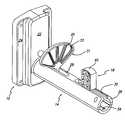
- FIG. 1is a perspective view of a cut-away printer having a rack and pinion medium roll support according to the present invention incorporated therein.
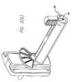
- FIG. 2 ais a detailed perspective view of the rack and pinion medium roll support in FIG. 1 having a left and right levers respectively positioned at opposite sides near the center of a support shaft.
- FIG. 2 bis a detailed perspective view of the rack and pinion medium roll support in FIG. 1 having the left and right levers respectively positioned at their far left and far right positions on the support shaft.
- FIG. 2 cis a detailed perspective view of the rack and pinion medium roll support in FIG. 1 having the right lever at a horizontal position.
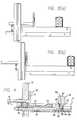
- FIG. 3 ais a side view of the rack and pinion medium roll support in FIG. 2 a.
- FIG. 3 bis a side view of the rack and pinion medium roll support in FIG. 2 b.
- FIG. 4is a cross-sectional view of the rack and pinion medium roll support.
- FIG. 1shows a rack and pinion medium roll support 10 according to the present invention being incorporated into a printer 1 .
- the printer 1has a support frame 3 defining an internal compartment for housing components of the printer 1 , including the rack and pinion medium roll support 10 .
- the internal compartmentnormally is also sufficiently large to house a printing medium roll to be mounted on the rack and pinion medium roll support 10 .
- the rack and pinion medium roll support 10is securely coupled to the support frame 3 at a first inner side and near a rear end of the printer 1 , as shown in FIG. 1 .
- the rack and pinion medium roll support 10has a support shaft 14 securely coupled to a shaft holder 12 at a first end, thereby the support shaft is substantially perpendicular to the shaft holder 12 .
- the support shaft 14is coupled to the shaft holder 12 by fixing means, such as screws, threaded into the support shaft 14 from the back side of the shaft holder 12 .
- the support shaft 14may be glued to or be screwed into the shaft holder 12 .
- the shaft holder 12has a stepped feature on a front side facing the support shaft 14 .
- a back side of the shaft holder 12has a substantially reversed stepped feature to the front side such that the back side of the shaft holder 12 has a stepped hollow recess for housing parts of a rack and pinion mechanism 16 of the present invention, as will be explained in detail in the following paragraphs.
- the front side of the shaft holder 12has a generally rectangular top step 22 fixedly positioned on top of a generally rectangular base step 24 .
- the top step 22has an opening near its bottom end, wherein the support shaft 14 is securely coupled to the top step 22 surrounding the opening.
- the top step 22is of approximately 1.4 inches wide by 3.77 inches long and 0.35 inches high
- the base step 24is of approximately 2.4 inches wide by 3.77 inches long and 0.35 inches high.
- FIG. 1also shows the shaft holder 12 being coupled to the support frame 3 of the printer 1 at a upper half of the internal compartment so that the support shaft 14 is substantially cantilevered inside the internal compartment of the printer 1 defined by the support frame 3 .
- the shaft holder 12is molded of plastic materials, but other suitable materials may be used to make the shaft holder 12 .
- the body of the support shaft 14is formed by a generally tubular shape body wall 26 having a pair of substantially concentric outer and inner surfaces.
- the body wall 26has an elongated and substantially circular-tube shape, wherein its outer diameter is of approximately 0.98 inches and its inner diameter is of approximately 0.63 inches. A surface portion of the body wall 26 is removed throughout the elongated body of the support shaft 14 , as shown in FIG. 2 a, thereby a flat top portion of the support shaft 14 will face up when the support shaft 14 is mounted on the shaft holder 12 .
- the support shaft 14also has an inner and an outer elongated opening slots 28 , 30 respectively positioned within the flat surface portion of the body wall 26 and extending from opposite ends of the body wall 26 toward the center of the support shaft 14 by approximately 2 inches.
- the inner and outer opening slots 28 , 30respectively have a width of approximately 0.22 inches and are formed by removing materials of the body wall 26 at their respective locations.
- the rack and pinion mechanism 16 of the present inventioncomprises a pair of levers 20 , 18 , a rotatable pinion 36 , and a pair of toothed racks 34 , 38 respectively coupled to the pair of levers 20 , 18 .
- the pair of levers 20 , 18includes an inner lever 20 and an outer lever 18 , wherein the inner lever 20 is slidably positioned on the inner opening slot 28 near the shaft holder 12 and the outer lever 18 is slidably positioned on the outer opening slot 30 away from the shaft holder 12 .
- the inner lever 20has a substantially fan shaped top section 31 and an L-shaped extrusion 32 coupled to the stem of the top section 31 , as shown in FIG. 4 .
- the inner lever 20has five radial spokes 33 on the top section 31 extending from the root of the L-shaped extrusion 32 upward, and a circumferential perimeter connected to the outer ends of each of the five spokes 33 .
- the radial spokes 33are substantially positioned in a same plane and are approximately one inch long, respectively.
- the two outmost radial spokes (far left and far right) of the inner lever 20together form an inner angle of approximately 160° therein between.
- the L-shaped extrusion 32 of the inner lever 20is inserted into the inner opening slot 28 .
- the bottom of the L-shaped extrusion 32is approximately 0.8 inches long extending from the top section 31 toward the center of the support shaft 14 .
- a lever support 52is positioned under the inner opening slot 28 within the support shaft 14 .
- the lever support 52has a stepped top surface near a first end to receive the bottom portion of the L-shaped extrusion 32 and has a slant top surface near a second end, whereby the L-shaped extrusion 32 can be slidably positioned on the top surface of the lever support 52 between these two ends.
- the lever support 52is tightly trapped between an inner lever rack 34 and an outer lever rack 38 inside the support shaft 14 , as shown in FIG. 4 .
- the lever support 52can be securely coupled to the support shaft 14 by fixing means, such as screws, or by gluing to the support shaft 14 .
- the first end of the lever support 52is positioned next to the pinion 36 and is curved to have a diameter slightly larger than the diameter of the pinion 36 .
- the second end of the lever support 52is located at approximately the center of the support shaft 14 .
- the depth of the stepped top surface of the lever support 52is approximately 0.25 inches long, which is substantially sufficient to house the bottom of the L-shaped extrusion 32 within the inner opening slot 28 .
- the pair of toothed racksincludes the inner lever rack 34 and the outer lever rack 38 .
- the inner lever rack 34is perpendicularly coupled to the inner lever 20 at the stem of the spokes 33 .
- the inner lever rack 34has an elongated shape of approximately 2.46 inches long and extends from the stem of the inner lever 20 through the opening of the shaft holder 12 toward the back side.
- the inner lever rack 34has rack teeth along a portion of the side facing the bottom end of the shaft holder 12 .
- the rack teeth of the inner lever rack 34are adapted to mesh with the pinion 36 positioned under the inner lever rack 34 , as shown in FIG. 4 .
- the pinion 36will move the inner lever 20 toward the center of the support shaft 14 by rotating at a first rotational direction and will move the inner lever 20 toward the shaft holder 12 , i.e., away from the center of the support shaft 14 , by rotating at a second rotational direction, opposite to the first.
- the pinionis rotatably coupled to the inner lever rack 34 and the outer lever rack 38 at diametrically opposite ends and is substantially positioned inside the back side of the shaft holder 12 .
- the inner lever rack 34 and the inner lever 20are integrally molded with plastic materials. In other embodiments, the inner lever rack 34 and the inner lever 20 may be formed separately, or they may be made of different materials.
- the rack and pinion mechanism 16further comprises the outer lever rack 38 slidably positioned within the support shaft 14 through the opening of the shaft holder 12 . Furthermore, a portion of the outer lever rack 38 is positioned between the lever support 52 and the inner surface of the support shaft 14 .
- the outer lever rack 38is approximately 5.75 inches long, which is considerably longer than the inner lever rack 34 , thereby an outer end of the outer lever rack 38 is adapted to be coupled to the outer lever 18 .
- the outer lever rack 38also has rack teeth along a portion of the side facing the pinion 36 . As a result, the inner lever rack 34 and the outer lever rack 38 respectively mesh with the pinion 36 at diametrically opposite sides of the pinion 36 .
- the pinion 36will move the outer lever 18 toward the center of the support shaft 14 by rotating at the first rotational direction and will move the outer lever 18 toward the open end of the support shaft 14 , i.e., away from the center of the support shaft 14 , by rotating at the second rotational direction, opposite to the first.
- the outer lever 18has a brick shape top section 40 .
- the top section 40has six square holes arranged in two rows, three in each row, along a longer side of the top section 40 , as shown in FIG. 2 a.
- the shape of the top section 40the number of the holes, the shape of the holes, or the arrangement of the holes could all be modified.
- the top section 40 of the outer lever 18has a dimension of approximately one inch high, 0.4 inches wide, and 0.74 inches thick.
- the outer lever 18also has a neck section 42 extending downward from the bottom of the top section 40 .
- the neck section 42is thinner than the top section 40 and is adapted to be inserted into the outer opening slot 30 , as shown in FIG. 2 .
- the neck section 42is approximately 0.45 inches long, thereby it could contact the outer lever rack 38 at the bottom.
- the bottom end of the neck section 42has a cam shape.
- the outer end of the outer lever rack 38has a vertical wall 48 and a front extension 50 .
- the front extension 50has a cam section 58 and a front wall 46 , wherein the cam shape bottom of the neck section 42 is adapted to directly contact the cam section 58 of the front extension 50 .
- the front wall 46has a generally round shape face having an outer diameter slightly smaller than the inner diameter of the support shaft 14 .
- a vertical slot 60extending from the top of the front wall 46 toward the bottom half is formed. The vertical slot 60 is approximately 0.46 inches long and 0.15 inches wide.
- the width of the vertical slot 60is slightly larger than the thickness of the neck section 42 of the outer lever 18 , thereby a portion of the neck section 42 could move freely along the vertical slot 60 .
- the neck section 42is pivotally coupled to the front wall 46 through a pivot pin 56 .
- the outer lever 18could pivotally rotate against the cam section 58 of the front extension 50 through the pivot pin 56 .
- the bottom inner surface of the support shaft 14has a groove 54 extending from near the outer end inward of approximately 2 inches.
- the bottom of the front extension 50is situated on the groove 54 , whereby the front extension 50 is confined to move within the support shaft 14 along the groove 54 .
- the outer lever 18is adapted to swing approximately 90° between a substantially vertical position and a substantially horizontal position, as shown respectively in FIGS. 2 b and 2 c. Since the top section 40 is thicker than the width of the outer opening slot 30 , the outer lever 18 is capable of being positioned horizontally only when it is at the outer end of the support shaft 14 , FIG. 2 c.
- a contacting block 44is securely mounted on a front surface of the vertical wall 48 facing the outer lever 18 .
- the contacting block 44is positioned at the top of the front surface of the vertical wall 48 , whereby the top surface of the contacting block 44 is substantially flush with the top surface of the vertical wall 48 .
- the contacting block 44functions as a stop for the outer lever 18 when the outer lever reaches its vertical position, as shown in FIG. 4 .
- the outer lever 18has to be initially positioned horizontally at the outer end of the outer opening slot 30 , as shown in FIG. 2 c. The user may thereafter insert the printing medium roll over the outer lever 18 and onto the support shaft 14 . After the printing medium roll is securely mounted on the support shaft 14 , the outer lever 18 shall be swung 90° to be positioned vertically. Thus, the printing medium roll is securely trapped between the inner and outer levers 20 , 18 and will not accidentally fall off the support shaft 14 .
- the lengths of the inner lever rack 34 and the outer lever rack 38are carefully selected, thereby the inner lever 20 and the outer lever 18 are approximately equally distanced from the center of the support shaft 14 , or from a center point defined by opposite ends of the support frame 3 .
- the inner lever rack 34 and the outer lever rack 38are diametrically meshed with the pinion 36 .
- the printing medium roll mounted on the support shaft 14will be approximately center-adjusted with respect to the support shaft 14 or to the support frame 3 .
Landscapes
- Unwinding Webs (AREA)
- Transmission Devices (AREA)
Abstract
Description
Claims (17)
Priority Applications (6)
| Application Number | Priority Date | Filing Date | Title |
|---|---|---|---|
| US09/477,996US6302604B1 (en) | 2000-01-05 | 2000-01-05 | Rack and pinion medium roll support |
| CA002312123ACA2312123C (en) | 2000-01-05 | 2000-06-22 | A rack and pinion medium roll support |
| AU47202/00AAU756809B2 (en) | 2000-01-05 | 2000-07-13 | A rack and pinion medium roll support |
| DE10045361ADE10045361A1 (en) | 2000-01-05 | 2000-09-14 | Roll holder, especially for paper rolls, has toothed rod mechanism mounted to slide partly within guide shaft and in shaft holder and to align roll centrally on guide shaft |
| MXPA00009271AMXPA00009271A (en) | 2000-01-05 | 2000-09-21 | Rack and pinion medium roll support. |
| FR0013950AFR2803244A1 (en) | 2000-01-05 | 2000-10-30 | RACK INFORMATION RACK SUPPORT WITH RACK |
Applications Claiming Priority (1)
| Application Number | Priority Date | Filing Date | Title |
|---|---|---|---|
| US09/477,996US6302604B1 (en) | 2000-01-05 | 2000-01-05 | Rack and pinion medium roll support |
Publications (1)
| Publication Number | Publication Date |
|---|---|
| US6302604B1true US6302604B1 (en) | 2001-10-16 |
Family
ID=23898136
Family Applications (1)
| Application Number | Title | Priority Date | Filing Date |
|---|---|---|---|
| US09/477,996Expired - LifetimeUS6302604B1 (en) | 2000-01-05 | 2000-01-05 | Rack and pinion medium roll support |
Country Status (6)
| Country | Link |
|---|---|
| US (1) | US6302604B1 (en) |
| AU (1) | AU756809B2 (en) |
| CA (1) | CA2312123C (en) |
| DE (1) | DE10045361A1 (en) |
| FR (1) | FR2803244A1 (en) |
| MX (1) | MXPA00009271A (en) |
Cited By (50)
| Publication number | Priority date | Publication date | Assignee | Title |
|---|---|---|---|---|
| US20030007823A1 (en)* | 2001-07-09 | 2003-01-09 | Nagano Fujitsu Component Limited | Printing apparatus and terminal apparatus |
| US20030141655A1 (en)* | 2002-01-25 | 2003-07-31 | Philip Bryer | Print media guide system |
| US6609844B1 (en)* | 2001-11-09 | 2003-08-26 | Zih Corp. | Portable printer having automatic print alignment |
| US6622622B2 (en)* | 2002-02-27 | 2003-09-23 | Korea Printing Systems Co., Ltd. | Adjustable paper guide device |
| US6698683B2 (en)* | 2002-06-28 | 2004-03-02 | George E. Young | Bathroom tissue dispenser and holder |
| US6758434B2 (en)* | 2002-07-03 | 2004-07-06 | Kimberly-Clark Worldwide, Inc. | Dispenser for multiple rolls of sheet material |
| US20050029391A1 (en)* | 2003-05-09 | 2005-02-10 | Edward Cocciadiferro | Film unwind system with hinged spindle and electronic control of web tension |
| US6959891B2 (en)* | 2002-07-03 | 2005-11-01 | Kimberly-Clark Worldwide, Inc. | Dispenser for multiple rolls of sheet material |
| US20060024114A1 (en)* | 2004-07-29 | 2006-02-02 | Zih Corp. | Printer assembly and method of using the same |
| US20060022039A1 (en)* | 2004-07-29 | 2006-02-02 | Zih Corp. | Universal card reader apparatus and method |
| US20060049253A1 (en)* | 2004-09-07 | 2006-03-09 | Zih Corp. | Printer having integrated communication port |
| US20060147243A1 (en)* | 2004-02-17 | 2006-07-06 | Blanchard Raymond A Jr | Spindle assembly |
| US7128291B1 (en)* | 2004-07-06 | 2006-10-31 | Brady Worldwide, Inc. | Spool having an extractor bar |
| US20070212150A1 (en)* | 2004-01-06 | 2007-09-13 | Brother Kogyo Kabushiki Kaisha | Roll sheet holder and tape printer |
| USD552165S1 (en)* | 2003-12-09 | 2007-10-02 | Daisey Machinery Co., Ltd. | Line thermal head letter printing apparatus |
| US20080279606A1 (en)* | 2007-05-08 | 2008-11-13 | Ching-Wen Chen | Label tensioning board of label printer |
| EP2036845A2 (en) | 2007-09-17 | 2009-03-18 | Avery Dennison Corporation | Mounting assembly and method of loading and/or unloading rolls |
| US20090175670A1 (en)* | 2008-01-07 | 2009-07-09 | Ching-Wen Chen | Label roll rack of barcode printer |
| US20090214281A1 (en)* | 2008-02-25 | 2009-08-27 | Makley James A | Portable printer and methods |
| US20110200375A1 (en)* | 2010-02-16 | 2011-08-18 | Datamax-O'neil Corporation | Portable printer with asymmetrically-damped media centering |
| WO2013078337A1 (en) | 2011-11-22 | 2013-05-30 | Source Technologies, Llc | Synchronized media hanger/guide |
| US8687032B2 (en) | 2011-06-06 | 2014-04-01 | Datamax-O'neil Corporation | Printing ribbon security apparatus and method |
| US8730287B2 (en) | 2011-06-24 | 2014-05-20 | Datamax-O'neil Corporation | Ribbon drive assembly |
| US8736650B2 (en) | 2011-06-23 | 2014-05-27 | Datamax-O'neil Corporation | Print station |
| US8810617B2 (en) | 2011-06-24 | 2014-08-19 | Datamax-O'neil Corporation | Apparatus and method for determining and adjusting printhead pressure |
| US8829481B2 (en) | 2011-10-20 | 2014-09-09 | Datamax-O'neil Corporation | Top of form sensor |
| US8842143B2 (en) | 2011-08-05 | 2014-09-23 | Datamax-O'neil Corporation | Printing system |
| US8842142B2 (en) | 2011-08-05 | 2014-09-23 | Datamax-O'neil Corporation | Print station system |
| US8882374B2 (en) | 2012-05-25 | 2014-11-11 | Datamax—O'Neil Corporation | Printer with print frame interlock and adjustable media support |
| US20150093172A1 (en)* | 2013-09-27 | 2015-04-02 | Transact Technologies Incorporated | Self-adjusting paper bucket for a printer and methods for providing a self-adjusting paper bucket |
| US9024988B2 (en) | 2011-12-22 | 2015-05-05 | Datamax-O'neil Corporation | Media detection apparatus and method |
| US9061527B2 (en) | 2012-12-07 | 2015-06-23 | Datamax-O'neil Corporation | Thermal printer with single latch, adjustable media storage and centering assemblies and print assembly |
| US9219836B2 (en) | 2011-05-23 | 2015-12-22 | Datamax-O'neil Corporation | Sensing apparatus for detecting and determining the width of media along a feed path |
| CN105437787A (en)* | 2015-12-14 | 2016-03-30 | 广州市宝比万像科技有限公司 | Roller and printer |
| CN105437789A (en)* | 2015-12-14 | 2016-03-30 | 广州市宝比万像科技有限公司 | Roller and printer |
| US9481186B2 (en) | 2011-07-14 | 2016-11-01 | Datamax-O'neil Corporation | Automatically adjusting printing parameters using media identification |
| EP2711190A3 (en)* | 2011-06-29 | 2017-01-11 | Fujitsu Component Limited | Printer |
| US9676216B2 (en) | 2014-03-27 | 2017-06-13 | Datamax-O'neil Corporation | Systems and methods for automatic printer configuration |
| US20180079542A1 (en)* | 2015-03-19 | 2018-03-22 | Ishida Co., Ltd. | Film roll supporting device |
| US10287129B2 (en)* | 2016-10-10 | 2019-05-14 | Caterpillar Inc. | Spool holder and method of supporting spool of wire with spool holder |
| US10611588B2 (en) | 2017-10-30 | 2020-04-07 | Transact Technologies Incorporated | Two-part spindle mechanism for a printer paper bucket, a printer paper bucket, and a printer having a paper bucket with a two-part spindle mechanism |
| US10807390B2 (en) | 2017-10-30 | 2020-10-20 | Transact Technologies Incorporated | Pivot mechanism for a printer and a printer with a pivoting printer housing |
| US10974925B2 (en) | 2018-12-14 | 2021-04-13 | Transact Technologies Incorporated | Spindle assembly for a printer for accommodating paper rolls of different sizes |
| CN112810325A (en)* | 2021-02-03 | 2021-05-18 | 重庆品胜物联网技术有限公司 | Printer label limit structure and printer |
| IT202000009601A1 (en) | 2020-04-30 | 2021-10-30 | Vimar Spa | PACKAGE FOR PLATES FOR ELECTRICAL INSTALLATIONS, KIT INCLUDING A PLATE FOR ELECTRICAL INSTALLATIONS AND A RELATED PACKAGE AND METHOD FOR PROTECTED PACKAGING OF PLATES FOR ELECTRICAL AND SIMILAR SYSTEMS |
| US20220289517A1 (en)* | 2019-12-20 | 2022-09-15 | Fujitsu Frontech Limited | Roll support device |
| EP4360894A1 (en)* | 2022-10-26 | 2024-05-01 | Toshiba TEC Kabushiki Kaisha | Printer |
| US20240351814A1 (en)* | 2023-04-19 | 2024-10-24 | Toshiba Tec Kabushiki Kaisha | Paper conveying device |
| US12319052B2 (en)* | 2021-12-24 | 2025-06-03 | Star Micronics Co., Ltd. | Printer |
| US12441129B2 (en) | 2022-10-26 | 2025-10-14 | Toshiba Tec Kabushiki Kaisha | Printer |
Families Citing this family (1)
| Publication number | Priority date | Publication date | Assignee | Title |
|---|---|---|---|---|
| AT523602B1 (en)* | 2020-03-06 | 2022-04-15 | Haslacher & Haslacher Immobilien Gmbh | ROLLING MANDREL |
Citations (3)
| Publication number | Priority date | Publication date | Assignee | Title |
|---|---|---|---|---|
| US5486259A (en)* | 1994-01-05 | 1996-01-23 | Monarch Marking Systems, Inc. | Labeler with adjustable roll mounting means |
| US5813343A (en)* | 1995-10-23 | 1998-09-29 | Eltron International, Inc. | Printing media roll mounting and positioning mechanism |
| US5833377A (en)* | 1996-05-10 | 1998-11-10 | Monarch Marking Systems, Inc. | Core, spindle and combination thereof |
Family Cites Families (3)
| Publication number | Priority date | Publication date | Assignee | Title |
|---|---|---|---|---|
| DE3631205A1 (en)* | 1986-09-13 | 1988-03-24 | Focke & Co | DEVICE FOR FEEDING PACKING MATERIAL BOBINES TO A PACKING MACHINE |
| EP0360400B1 (en)* | 1988-08-23 | 1993-07-28 | Tokyo Electric Co., Ltd. | Web roll holding device |
| JP3682515B2 (en)* | 1996-12-24 | 2005-08-10 | 株式会社サトー | Belt-shaped support reel |
- 2000
- 2000-01-05USUS09/477,996patent/US6302604B1/ennot_activeExpired - Lifetime
- 2000-06-22CACA002312123Apatent/CA2312123C/ennot_activeExpired - Fee Related
- 2000-07-13AUAU47202/00Apatent/AU756809B2/ennot_activeCeased
- 2000-09-14DEDE10045361Apatent/DE10045361A1/ennot_activeWithdrawn
- 2000-09-21MXMXPA00009271Apatent/MXPA00009271A/enactiveIP Right Grant
- 2000-10-30FRFR0013950Apatent/FR2803244A1/ennot_activeWithdrawn
Patent Citations (3)
| Publication number | Priority date | Publication date | Assignee | Title |
|---|---|---|---|---|
| US5486259A (en)* | 1994-01-05 | 1996-01-23 | Monarch Marking Systems, Inc. | Labeler with adjustable roll mounting means |
| US5813343A (en)* | 1995-10-23 | 1998-09-29 | Eltron International, Inc. | Printing media roll mounting and positioning mechanism |
| US5833377A (en)* | 1996-05-10 | 1998-11-10 | Monarch Marking Systems, Inc. | Core, spindle and combination thereof |
Cited By (86)
| Publication number | Priority date | Publication date | Assignee | Title |
|---|---|---|---|---|
| US20030007823A1 (en)* | 2001-07-09 | 2003-01-09 | Nagano Fujitsu Component Limited | Printing apparatus and terminal apparatus |
| US6814515B2 (en)* | 2001-07-09 | 2004-11-09 | Nagano Fujitsu Component Limited | Printing apparatus and terminal apparatus |
| US6609844B1 (en)* | 2001-11-09 | 2003-08-26 | Zih Corp. | Portable printer having automatic print alignment |
| US20040018035A1 (en)* | 2001-11-09 | 2004-01-29 | Petteruti Steven F. | Portable printer having automatic print alignment |
| US7033097B2 (en) | 2001-11-09 | 2006-04-25 | Zih Corp. | Portable printer having automatic print alignment |
| US20030141655A1 (en)* | 2002-01-25 | 2003-07-31 | Philip Bryer | Print media guide system |
| US7004462B2 (en) | 2002-01-25 | 2006-02-28 | Zih Corp. | Print media guide system |
| US6622622B2 (en)* | 2002-02-27 | 2003-09-23 | Korea Printing Systems Co., Ltd. | Adjustable paper guide device |
| US6698683B2 (en)* | 2002-06-28 | 2004-03-02 | George E. Young | Bathroom tissue dispenser and holder |
| US6758434B2 (en)* | 2002-07-03 | 2004-07-06 | Kimberly-Clark Worldwide, Inc. | Dispenser for multiple rolls of sheet material |
| US6959891B2 (en)* | 2002-07-03 | 2005-11-01 | Kimberly-Clark Worldwide, Inc. | Dispenser for multiple rolls of sheet material |
| US20050029391A1 (en)* | 2003-05-09 | 2005-02-10 | Edward Cocciadiferro | Film unwind system with hinged spindle and electronic control of web tension |
| US7959103B2 (en) | 2003-05-09 | 2011-06-14 | Pregis Intellipack Corporation | Film unwind system with hinged spindle and electronic control of web tension |
| US20080179446A1 (en)* | 2003-05-09 | 2008-07-31 | Edward Cocciadiferro | Film unwind system with hinged spindle and electronic control of web tension |
| US7331542B2 (en)* | 2003-05-09 | 2008-02-19 | Intellipack | Film unwind system with hinged spindle and electronic control of web tension |
| USD552165S1 (en)* | 2003-12-09 | 2007-10-02 | Daisey Machinery Co., Ltd. | Line thermal head letter printing apparatus |
| US20070212150A1 (en)* | 2004-01-06 | 2007-09-13 | Brother Kogyo Kabushiki Kaisha | Roll sheet holder and tape printer |
| US7404684B2 (en)* | 2004-01-06 | 2008-07-29 | Brother Kogyo Kabushiki Kaisha | Roll sheet holder and tape printer |
| US7497401B2 (en) | 2004-02-17 | 2009-03-03 | Paxar Americas, Inc. | Printer and stacker and methods |
| US20070014619A1 (en)* | 2004-02-17 | 2007-01-18 | Ward Donald J | Center-justifying spindle assembly |
| US20080075514A1 (en)* | 2004-02-17 | 2008-03-27 | Blanchard Raymond A Jr | Printer and stacker and methods |
| US7350992B2 (en)* | 2004-02-17 | 2008-04-01 | Paxar Americas, Inc. | Center-justifying spindle assembly |
| US7350463B2 (en)* | 2004-02-17 | 2008-04-01 | Paxar Americas, Inc. | Spindle assembly |
| US20060147243A1 (en)* | 2004-02-17 | 2006-07-06 | Blanchard Raymond A Jr | Spindle assembly |
| US9079742B2 (en) | 2004-02-17 | 2015-07-14 | Avery Dennison Corporation | Printer with latch for releasably holding a platen roll |
| US20090202285A1 (en)* | 2004-02-17 | 2009-08-13 | Paxar Americas, Inc. | Printer |
| US7128291B1 (en)* | 2004-07-06 | 2006-10-31 | Brady Worldwide, Inc. | Spool having an extractor bar |
| US20060022039A1 (en)* | 2004-07-29 | 2006-02-02 | Zih Corp. | Universal card reader apparatus and method |
| US7441701B2 (en) | 2004-07-29 | 2008-10-28 | Zih Corp. | Universal card reader apparatus and method |
| US20060024114A1 (en)* | 2004-07-29 | 2006-02-02 | Zih Corp. | Printer assembly and method of using the same |
| US20060049253A1 (en)* | 2004-09-07 | 2006-03-09 | Zih Corp. | Printer having integrated communication port |
| US8231289B2 (en)* | 2007-05-08 | 2012-07-31 | Tsc Auto Id Technology Co., Ltd. | Label tensioning board of label printer |
| US20080279606A1 (en)* | 2007-05-08 | 2008-11-13 | Ching-Wen Chen | Label tensioning board of label printer |
| US20090072073A1 (en)* | 2007-09-17 | 2009-03-19 | Campbell Donald A | Mounting assembly and method of loading and/or unloading rolls |
| EP2036845A2 (en) | 2007-09-17 | 2009-03-18 | Avery Dennison Corporation | Mounting assembly and method of loading and/or unloading rolls |
| US8568046B2 (en) | 2007-09-17 | 2013-10-29 | Avery Dennison Corporation | Mounting assembly and method of loading and/or unloading rolls |
| US20090175670A1 (en)* | 2008-01-07 | 2009-07-09 | Ching-Wen Chen | Label roll rack of barcode printer |
| US8721208B2 (en)* | 2008-02-25 | 2014-05-13 | Avery Dennison Corporation | Portable printer and methods |
| US20090214281A1 (en)* | 2008-02-25 | 2009-08-27 | Makley James A | Portable printer and methods |
| US10363764B2 (en)* | 2008-02-25 | 2019-07-30 | Avery Dennison Corporation | Portable printer and methods |
| US20140210936A1 (en)* | 2008-02-25 | 2014-07-31 | Avery Dennison Corporation | Portable printer and methods |
| US20110200375A1 (en)* | 2010-02-16 | 2011-08-18 | Datamax-O'neil Corporation | Portable printer with asymmetrically-damped media centering |
| US8783980B2 (en) | 2010-02-16 | 2014-07-22 | Datamax-O'neil Corporation | Portable printer with asymmetrically-damped media centering |
| US8475065B2 (en) | 2010-02-16 | 2013-07-02 | Datamax-O'neil Corporation | Portable printer with asymmetrically-damped media centering |
| US9219836B2 (en) | 2011-05-23 | 2015-12-22 | Datamax-O'neil Corporation | Sensing apparatus for detecting and determining the width of media along a feed path |
| US9079423B2 (en) | 2011-06-06 | 2015-07-14 | Datamax-O'neil Corporation | Printing ribbon security apparatus and method |
| US8687032B2 (en) | 2011-06-06 | 2014-04-01 | Datamax-O'neil Corporation | Printing ribbon security apparatus and method |
| US8736650B2 (en) | 2011-06-23 | 2014-05-27 | Datamax-O'neil Corporation | Print station |
| US8810617B2 (en) | 2011-06-24 | 2014-08-19 | Datamax-O'neil Corporation | Apparatus and method for determining and adjusting printhead pressure |
| US8730287B2 (en) | 2011-06-24 | 2014-05-20 | Datamax-O'neil Corporation | Ribbon drive assembly |
| US10384479B2 (en) | 2011-06-29 | 2019-08-20 | Fujitsu Component Limited | Printer with tensioning guide unit |
| US9586422B2 (en) | 2011-06-29 | 2017-03-07 | Fujitsu Component Limited | Printer assembled from mainframe and multiple function units |
| EP2711190A3 (en)* | 2011-06-29 | 2017-01-11 | Fujitsu Component Limited | Printer |
| US9481186B2 (en) | 2011-07-14 | 2016-11-01 | Datamax-O'neil Corporation | Automatically adjusting printing parameters using media identification |
| US8842142B2 (en) | 2011-08-05 | 2014-09-23 | Datamax-O'neil Corporation | Print station system |
| US8842143B2 (en) | 2011-08-05 | 2014-09-23 | Datamax-O'neil Corporation | Printing system |
| US8829481B2 (en) | 2011-10-20 | 2014-09-09 | Datamax-O'neil Corporation | Top of form sensor |
| EP2782763A4 (en)* | 2011-11-22 | 2016-04-06 | Datamax O Neil Corp | SUSPENSION ELEMENT / SYNCHRONIZED OBJECT GUIDE |
| WO2013078337A1 (en) | 2011-11-22 | 2013-05-30 | Source Technologies, Llc | Synchronized media hanger/guide |
| US9193552B2 (en) | 2011-11-22 | 2015-11-24 | Datamax-O'neil Corporation | Synchronized media hanger/guide |
| USRE47928E1 (en) | 2011-12-22 | 2020-04-07 | Datamax-O'neil Corporation | Media detection apparatus and method |
| US9024988B2 (en) | 2011-12-22 | 2015-05-05 | Datamax-O'neil Corporation | Media detection apparatus and method |
| US8882374B2 (en) | 2012-05-25 | 2014-11-11 | Datamax—O'Neil Corporation | Printer with print frame interlock and adjustable media support |
| US9061527B2 (en) | 2012-12-07 | 2015-06-23 | Datamax-O'neil Corporation | Thermal printer with single latch, adjustable media storage and centering assemblies and print assembly |
| US9701137B2 (en) | 2012-12-07 | 2017-07-11 | Datamax-O'neil Corporation | Thermal printer with single latch, adjustable media storage and centering assemblies and print assembly |
| US9315054B2 (en)* | 2013-09-27 | 2016-04-19 | Transact Technologies Incorporated | Self-adjusting paper bucket for a printer and methods for providing a self-adjusting paper bucket |
| US20150093172A1 (en)* | 2013-09-27 | 2015-04-02 | Transact Technologies Incorporated | Self-adjusting paper bucket for a printer and methods for providing a self-adjusting paper bucket |
| US9676216B2 (en) | 2014-03-27 | 2017-06-13 | Datamax-O'neil Corporation | Systems and methods for automatic printer configuration |
| US10589885B2 (en)* | 2015-03-19 | 2020-03-17 | Ishida Co., Ltd. | Film roll support device |
| US20180079542A1 (en)* | 2015-03-19 | 2018-03-22 | Ishida Co., Ltd. | Film roll supporting device |
| CN105437787B (en)* | 2015-12-14 | 2018-02-23 | 广州市宝比万像科技有限公司 | Spool and printer |
| CN105437789B (en)* | 2015-12-14 | 2018-04-24 | 广州市宝比万像科技有限公司 | Spool and printer |
| CN105437787A (en)* | 2015-12-14 | 2016-03-30 | 广州市宝比万像科技有限公司 | Roller and printer |
| CN105437789A (en)* | 2015-12-14 | 2016-03-30 | 广州市宝比万像科技有限公司 | Roller and printer |
| US10287129B2 (en)* | 2016-10-10 | 2019-05-14 | Caterpillar Inc. | Spool holder and method of supporting spool of wire with spool holder |
| US10611588B2 (en) | 2017-10-30 | 2020-04-07 | Transact Technologies Incorporated | Two-part spindle mechanism for a printer paper bucket, a printer paper bucket, and a printer having a paper bucket with a two-part spindle mechanism |
| US10807390B2 (en) | 2017-10-30 | 2020-10-20 | Transact Technologies Incorporated | Pivot mechanism for a printer and a printer with a pivoting printer housing |
| US10974925B2 (en) | 2018-12-14 | 2021-04-13 | Transact Technologies Incorporated | Spindle assembly for a printer for accommodating paper rolls of different sizes |
| US20220289517A1 (en)* | 2019-12-20 | 2022-09-15 | Fujitsu Frontech Limited | Roll support device |
| US12139365B2 (en)* | 2019-12-20 | 2024-11-12 | Fujitsu Frontech Limited | Roll support device |
| IT202000009601A1 (en) | 2020-04-30 | 2021-10-30 | Vimar Spa | PACKAGE FOR PLATES FOR ELECTRICAL INSTALLATIONS, KIT INCLUDING A PLATE FOR ELECTRICAL INSTALLATIONS AND A RELATED PACKAGE AND METHOD FOR PROTECTED PACKAGING OF PLATES FOR ELECTRICAL AND SIMILAR SYSTEMS |
| CN112810325A (en)* | 2021-02-03 | 2021-05-18 | 重庆品胜物联网技术有限公司 | Printer label limit structure and printer |
| US12319052B2 (en)* | 2021-12-24 | 2025-06-03 | Star Micronics Co., Ltd. | Printer |
| EP4360894A1 (en)* | 2022-10-26 | 2024-05-01 | Toshiba TEC Kabushiki Kaisha | Printer |
| US12441129B2 (en) | 2022-10-26 | 2025-10-14 | Toshiba Tec Kabushiki Kaisha | Printer |
| US20240351814A1 (en)* | 2023-04-19 | 2024-10-24 | Toshiba Tec Kabushiki Kaisha | Paper conveying device |
Also Published As
| Publication number | Publication date |
|---|---|
| CA2312123A1 (en) | 2001-07-05 |
| AU756809B2 (en) | 2003-01-23 |
| CA2312123C (en) | 2003-02-11 |
| AU4720200A (en) | 2001-07-12 |
| FR2803244A1 (en) | 2001-07-06 |
| DE10045361A1 (en) | 2001-07-12 |
| MXPA00009271A (en) | 2005-04-28 |
Similar Documents
| Publication | Publication Date | Title |
|---|---|---|
| US6302604B1 (en) | Rack and pinion medium roll support | |
| US5555302A (en) | Mobile telephone holder | |
| US6256387B1 (en) | Device rack | |
| US4223714A (en) | Window shade roller assembly | |
| US5494346A (en) | Adjustable shelf assembly | |
| US20030053315A1 (en) | Recessed down light | |
| CN114810635A (en) | Fan with cooling device | |
| CN222089693U (en) | An embedded ceiling AP device | |
| US6866078B1 (en) | Sliding carriage for vertical blind | |
| AU2018100505A4 (en) | Roller blind | |
| JPH0120136Y2 (en) | ||
| JPH0910446A (en) | Drawing toy for infants | |
| CN223261573U (en) | Camera clamping focusing mechanism and rotating focusing device | |
| CN223392080U (en) | A card storage tool | |
| CN111115379A (en) | A label rewinding machine | |
| CN222533184U (en) | Reel torsion pre-release telescopic commodity shelf | |
| CN215792714U (en) | Winding-proof structure for winding color band | |
| CN223049337U (en) | A base belt transmission structure | |
| JP2000355145A (en) | Dustproof structure for printer | |
| JP2808931B2 (en) | Tape cassette insertion guide device | |
| JP3019144U (en) | Height adjusting device for magnetic head in magnetic tape device | |
| KR200241883Y1 (en) | A reading board | |
| JPH0514398Y2 (en) | ||
| KR200396467Y1 (en) | the desk | |
| JPS6323835Y2 (en) |
Legal Events
| Date | Code | Title | Description |
|---|---|---|---|
| AS | Assignment | Owner name:ELTRON INTERNATIONAL, INC., CALIFORNIA Free format text:ASSIGNMENT OF ASSIGNORS INTEREST;ASSIGNOR:BRYANT, CALEB;REEL/FRAME:010486/0796 Effective date:19991229 | |
| AS | Assignment | Owner name:ELTRON INTERNATIONAL, INC., CALIFORNIA Free format text:ASSIGNMENT OF ASSIGNORS INTEREST;ASSIGNORS:BRYANT, CALEB;BRASHEAR, BOB;REEL/FRAME:010662/0536 Effective date:20000221 | |
| AS | Assignment | Owner name:ZIH CORP., DELAWARE Free format text:ASSIGNMENT OF ASSIGNORS INTEREST;ASSIGNOR:ELTRON INTERNATIONAL, INC.;REEL/FRAME:011369/0594 Effective date:20001113 | |
| STCF | Information on status: patent grant | Free format text:PATENTED CASE | |
| AS | Assignment | Owner name:ZIH CORP., BERMUDA Free format text:RECORDATION OF ASSIGNEE'S PRINCIPAL PLACE OF BUSIN;ASSIGNOR:ZIH CORP.;REEL/FRAME:014154/0051 Effective date:20031104 | |
| FEPP | Fee payment procedure | Free format text:PAYOR NUMBER ASSIGNED (ORIGINAL EVENT CODE: ASPN); ENTITY STATUS OF PATENT OWNER: LARGE ENTITY | |
| FPAY | Fee payment | Year of fee payment:4 | |
| FPAY | Fee payment | Year of fee payment:8 | |
| FPAY | Fee payment | Year of fee payment:12 | |
| AS | Assignment | Owner name:MORGAN STANLEY SENIOR FUNDING, INC. AS THE COLLATERAL AGENT, MARYLAND Free format text:SECURITY AGREEMENT;ASSIGNORS:ZIH CORP.;LASER BAND, LLC;ZEBRA ENTERPRISE SOLUTIONS CORP.;AND OTHERS;REEL/FRAME:034114/0270 Effective date:20141027 Owner name:MORGAN STANLEY SENIOR FUNDING, INC. AS THE COLLATE Free format text:SECURITY AGREEMENT;ASSIGNORS:ZIH CORP.;LASER BAND, LLC;ZEBRA ENTERPRISE SOLUTIONS CORP.;AND OTHERS;REEL/FRAME:034114/0270 Effective date:20141027 | |
| AS | Assignment | Owner name:JPMORGAN CHASE BANK, N.A., AS THE SUCCESSOR AGENT, NEW YORK Free format text:PATENT SECURITY INTEREST ASSIGNMENT AGREEMENT;ASSIGNOR:MORGAN STANLEY SENIOR FUNDING, INC., AS THE EXISTING AGENT;REEL/FRAME:044791/0842 Effective date:20170907 Owner name:JPMORGAN CHASE BANK, N.A., AS THE SUCCESSOR AGENT, Free format text:PATENT SECURITY INTEREST ASSIGNMENT AGREEMENT;ASSIGNOR:MORGAN STANLEY SENIOR FUNDING, INC., AS THE EXISTING AGENT;REEL/FRAME:044791/0842 Effective date:20170907 | |
| AS | Assignment | Owner name:ZEBRA TECHNOLOGIES CORPORATION, ILLINOIS Free format text:MERGER;ASSIGNOR:ZIH CORP.;REEL/FRAME:048884/0618 Effective date:20181220 | |
| AS | Assignment | Owner name:JPMORGAN CHASE BANK, N.A., AS COLLATERAL AGENT, NE Free format text:NOTICE OF TRANSFER OF SECURITY INTEREST IN PATENTS;ASSIGNOR:ZEBRA TECHNOLOGIES CORPORATION;REEL/FRAME:049675/0049 Effective date:20190701 Owner name:JPMORGAN CHASE BANK, N.A., AS COLLATERAL AGENT, NEW YORK Free format text:NOTICE OF TRANSFER OF SECURITY INTEREST IN PATENTS;ASSIGNOR:ZEBRA TECHNOLOGIES CORPORATION;REEL/FRAME:049675/0049 Effective date:20190701 |