US6301291B1 - Pilot symbol assisted modulation and demodulation in wireless communication systems - Google Patents
Pilot symbol assisted modulation and demodulation in wireless communication systemsDownload PDFInfo
- Publication number
- US6301291B1 US6301291B1US09/497,440US49744000AUS6301291B1US 6301291 B1US6301291 B1US 6301291B1US 49744000 AUS49744000 AUS 49744000AUS 6301291 B1US6301291 B1US 6301291B1
- Authority
- US
- United States
- Prior art keywords
- frame
- pilot symbols
- data
- response
- symbols
- Prior art date
- Legal status (The legal status is an assumption and is not a legal conclusion. Google has not performed a legal analysis and makes no representation as to the accuracy of the status listed.)
- Expired - Lifetime
Links
Images


Classifications
- H—ELECTRICITY
- H04—ELECTRIC COMMUNICATION TECHNIQUE
- H04B—TRANSMISSION
- H04B1/00—Details of transmission systems, not covered by a single one of groups H04B3/00 - H04B13/00; Details of transmission systems not characterised by the medium used for transmission
- H04B1/76—Pilot transmitters or receivers for control of transmission or for equalising
- H—ELECTRICITY
- H04—ELECTRIC COMMUNICATION TECHNIQUE
- H04L—TRANSMISSION OF DIGITAL INFORMATION, e.g. TELEGRAPHIC COMMUNICATION
- H04L25/00—Baseband systems
- H04L25/02—Details ; arrangements for supplying electrical power along data transmission lines
- H04L25/0202—Channel estimation
- H04L25/0224—Channel estimation using sounding signals
- H04L25/0228—Channel estimation using sounding signals with direct estimation from sounding signals
- H—ELECTRICITY
- H04—ELECTRIC COMMUNICATION TECHNIQUE
- H04L—TRANSMISSION OF DIGITAL INFORMATION, e.g. TELEGRAPHIC COMMUNICATION
- H04L27/00—Modulated-carrier systems
- H04L27/18—Phase-modulated carrier systems, i.e. using phase-shift keying
- H04L27/22—Demodulator circuits; Receiver circuits
Definitions
- the present inventionrelates to a code division multiple access (CDMA) communication system and, more particularly, to pilot symbol assisted modulation and demodulation in the forward and reverse links of such a CDMA communication system.
- CDMAcode division multiple access
- CDMA modulationwhich is known in the art, is a multi-user access transmission scheme in which the signals of different users overlap both in frequency and in time. This is in contrast to Frequency Division Multiple Access (FDMA), also known in the art, in which the signals of users overlap in time, but are assigned unique frequencies, and Time Division Multiple Access (TDMA) in which the signals of users overlap in frequency, but are assigned unique timeslots.
- FDMAFrequency Division Multiple Access
- TDMATime Division Multiple Access
- each useris assigned a unique code sequence that is used to modulate the user's signals. This allows the user to spread the information over the entire channel bandwidth, as opposed to particular sub-channel(s) in FDMA.
- the signal for each user at a mobile stationis spread over a wide bandwidth, which is greater than the minimum bandwidth to transmit the signal.
- Each user's signalis spread by a different wideband code, each of which are orthogonal to each other. All the spread wideband signals for different users are added together to form a composite signal which is transmitted over the airwaves in the same frequency band.
- the receiver at a base station (BS)distinguishes among signals from different users by using a copy of the particular wideband code for a user, which is available to both the mobile stations and the base stations in the CDMA system. Such a process is called channelization.
- channelization in the reverse linki.e., when a mobile station (MS) is transmitting to a base station (BS) in the system, is accomplished using a wideband code called a pseudorandom noise (PN) code, also known in the art.
- PNpseudorandom noise
- the receiver at the base station (BS)sifts the desired signal from a particular user out of the composite signal by correlating the composite signal with the original wideband code. All other users having codes that do not match the code for the desired signal from that particular user are rejected.
- a central facet of wireless communication systemsis the reliability and integrity of the data which are being communicated.
- the data which are being transmitted from a transmitter of a wireless systemshould be identical to the data which are being received at a receiver thereof.
- the data which are received at the receiverhave often been corrupted with respect to the original data which were transmitted from the transmitter.
- Such data communication errorsmay be attributed to many factors, including multipath Rayleigh fading.
- the received signalsare made up of a group of reflections from objects, and none of the reflected signal paths is any more dominant than the other ones.
- the different reflected signal pathsarrive at slightly different times, with different amplitudes, and with different phases. Because there are many different signal paths, constructive and destructive interference can result, namely, multipath Rayleigh fading. Furthermore, jitter may also result which prevents proper signal sampling and in turn negatively affects the bit error rate (BER), which is directly related to the signal quality of a transmission path assigned to a particular user.
- BERbit error rate
- a wireless systemwith improved data reception.
- a wireless systemis particularly needed that enhances the signal quality at the receivers and minimizes the negative effects of multipath Rayleigh fading on data reception.
- a wireless systemthat prevents the occurrence of jitter with proper sampling and optimized bit error rate (BER).
- the present inventionis a method and system of data transmission using pilot symbol assisted modulation and demodulation.
- a preferred embodiment of the system according to the inventionincludes a transmitter having a QPSK (quadrature phase shift keying) modulator, and a receiver having a pilot correlation filter (PCF), a data matching filter (DMF), a timing recovery mechanism, a sampler, and a QPSK (quadrature phase shift keying) demodulator.
- the transmittertransmits a frame of data symbols and pilot symbols to a receiver in a wireless system.
- the pilot symbolsare inserted in the frame at known time intervals.
- the QPSK modulatormodulates the frame of data and pilot symbols using quadrature phase shift keying (QPSK) modulation.
- QPSKquadrature phase shift keying
- the PCFrecovers the pilot symbols from the frame and produces a multipath response.
- the timing recovery mechanismtracks the timing of the pilot symbols in the frame.
- the DMFenhances the multipath response of the frame of data and pilot symbols at the known time intervals of the pilot symbols, and outputs an enhanced multipath response signal with a plurality of enhanced peaks.
- the samplersamples the enhanced multipath response of the frame of data and pilot symbols.
- the QPSK demodulatordemodulates the sampled frame of data and pilot symbols and recovers the data symbols using quadrature phase shift keying (QPSK) demodulation based on the samples.
- QPSKquadrature phase shift keying
- a frame of data symbols and pilot symbolsare transmitted, where the pilot symbols are inserted in the frame at known time intervals.
- the frame of data and pilot symbolsare modulated using QPSK modulation.
- the pilot symbolsare recovered and a multipath response is provided for the received frame at the known time intervals of the pilot symbols through the use of a finite impulse response (FIR) filter.
- FIRfinite impulse response
- the multipath responseis hump-like in appearance in terms of its amplitude versus time.
- the multipath response of the received frameis enhanced by time reversal and complex conjugation to provide enhanced peaks of the multipath response.
- the enhanced multipath responseis sampled at each of the enhanced peaks and the data symbols of the received frame are recovered using QPSK demodulation based on the samples.
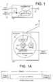
- FIG. 1is a diagram generally illustrating a transmitter and a receiver of a wireless system according to the invention
- FIG. 1Ais a diagram illustrating the frame structure of an exemplary frame of data and pilot symbols being transmitted in accordance with the invention
- FIG. 2is a diagram illustrating a QPSK modulator of the transmitter according to the invention.
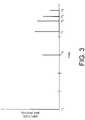
- FIG. 3is a diagram illustrating an exemplary multipath response of communicating a frame of data from a transmitter to a receiver in a wireless system
- FIG. 4is a diagram illustrating an exemplary QPSK demodulator having a data matching filter that enhances the multipath response in a receiver according to the invention
- FIG. 5is a diagram illustrating an exemplary pilot correlation filter according to the invention.
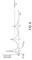
- FIG. 6is a diagram illustrating an exemplary threshold detection of a multipath response according to the invention.
- FIG. 6Ais a flow diagram illustrating a preferred embodiment of the method of the invention.
- FIG. 7is a diagram illustrating an exemplary phase estimator used in the receiver according to the invention.
- FIGS. 8A and 8Bare diagrams illustrating another embodiment of the QPSK demodulator according to the invention.
- FIG. 1is a diagram that generally illustrates a transmitter 10 and a receiver 20 in a wireless communication system according to the invention.
- the transmitter 10Tx 1
- the receiver 20Rx 2
- the transmitter Tx 1transmits a frame of data symbols 11 and pilot symbols 12 to the receiver Rx 2 .
- the transmissionis in the reverse link, i.e., from a transmitter in a mobile station (MS) to a receiver in a base station (BS) in the wireless system.
- MSmobile station
- BSbase station
- the transmissioncan also be in the forward link, i.e., from a transmitter in a base station (BS) to a receiver in a mobile station (MS) in the wireless system.
- the pilot symbols 12are inserted (at node 13 ) in the frame at known time intervals.
- the pilot symbols 12are inserted in an exemplary frame 1 as shown in FIG. 1A.
- P pilot symbolsare inserted into frame 1 which has a total of N symbols.
- the P pilot symbolsare inserted in the front end of frame 1 , with N-P data symbols appended thereto.
- Each symbolcan be further divided into smaller sampling units such as “chips” which is a term of art in CDMA.
- a chipis a unit for a minimum sampling period for a frame of data/pilot symbols.
- the sampling period for a chip (denoted Tc) in IS-95which is a North American CDMA standard known in the art, is 1 1 , 228 , 800
- the number of samples taken in a chipvaries, depending on the CDMA design. For example, one sample can be taken for each chip, or oversampling can be applied to each chip so that a chip includes a plurality of samples. In this particular embodiment according to the invention, each chip in the frame of data/pilot symbols being transmitted is oversampled four times, i.e., there are 4 samples for each chip.
- the QPSK modulator 14modulates the frame of data and pilot symbols ( 11 and 12 ) using quadrature phase shift keying (QPSK), known in the art, which is a modulation technique that allows the transmission of two bits of information in each symbol period.
- QPSK modulationmakes use of the quadrature component in addition to the in-phase component of a symbol in the frame being transmitted from the transmitter 10 to the receiver 20 .
- the in-phase component, I, and the quadrature component, Qcan be combined without interfering with each other (i.e., they are orthogonal to each other) which doubles the bandwidth efficiency in comparison with simply transmitting one bit of information in a symbol period.
- the receiver 20receives the QPSK-modulated frame of data and pilot symbols ( 11 and 12 ) from the transmitter 10 via antennae 15 and 16 .
- the pilot correlation filter PCF 23recovers the pilot symbols in the modulated frame received from the transmitter 10 and outputs a hump-like multipath response to the data matching filter DMF 22 .
- the multipath responseis hump-like at this point due to interference such as multipath Rayleigh fading.
- the DMF 22enhances the multipath response of the frame of data and pilot symbols ( 11 and 12 ) at the known time intervals of the pilot symbols recovered by the PCF 23 , and outputs a plurality of enhanced peaks.
- the sampler 24samples the multipath response of the frame of data and pilot symbols ( 11 and 12 ) at each of the enhanced peaks.
- the QPSK demodulator 26then completes the demodulation of the sampled frame of data and pilot symbols ( 11 and 12 ) and outputs the recovered data symbols.
- FIG. 2is a diagram that illustrates a QPSK modulator of the transmitter 10 according to the invention.
- the frame 201 of data and pilot symbols( 11 and 12 in FIG. 1) is respectively input into the adders 207 and 209 .
- the channel separator 203which is connected to the adders 207 and 209 , separates or spreads the frame 201 into two data streams (I and Q) by multiplying the frame 201 with cosine and sine carrier waveforms, respectively, which have the same frequency.
- Pseudorandom noise (PN) and user code generator 205spreads the frame 201 of data and pilot symbols over the entire bandwidth of the I and Q streams by inserting a PN code ⁇ Pn ⁇ and a user code at adders 211 and 213 .
- the receiver 20also possesses a copy of the PN ⁇ Pn ⁇ code for data recovery.
- the I and Q streamsare bandpass filtered at the filters H(Z) 215 and 217 , respectively.
- An oscillator, VCO 219generates a carrier waveform which is multiplied with the I and Q streams at multiplier 221 and 223 , respectively.
- the I and Q streamsare combined at adder 225 which outputs the modulated frame 1 of data and pilot symbols which are transmitted from the antenna 15 of transmitter 10 to the antenna 16 of the receiver ( 20 of FIG. 1 ).
- the data received at the receiver Rx 2 which includes the modulated frame 1can be represented with respect to the PN code ⁇ Pn ⁇ as a function of time t and the sampling period for a chip Tc in the modulated frame 1 .
- Nis the number of symbols in the modulated frame 1 , ⁇ n N ⁇
- ⁇is a function of white noise (a factor known in the art)
- h(t)represents the channel and filtering effects (as a function of time t) in the data transmission path between the transmitter 10 and the receiver 20
- n(t)represents noise (as a function of time t) in the data transmission path between the transmitter and receiver.
- White noiseis an approximation of the noise and/or interference that naturally occurs in data transmission, including thermal noise, which is produced by the random motion of electrons in the transmission medium, and shot noise, which is the variation around the average value of a current of discrete pulses between two points in the transmission medium.
- d(which represents the encoded bits for the nth chip) stays constant for each chip in the modulated frame 1 until the full frame of N ⁇ 32 symbols is processed.
- FIG. 3is a diagram that illustrates an exemplary multipath response of communicating a frame of data from a transmitter to a receiver in a wireless system.
- the transmitter ( 10 of FIG. 1)transmits the modulated frame at time t x .
- the receiver ( 20 of FIG. 1)receives a series of pulses or peaks at t0, t1, t2, t3 and t4 which represent the modulated frame 1 of data and pilot symbols transmitted from 20 , but received at the receiver 20 over various transmitter paths of different length.
- the receiver having a QPSK demodulatorenhances the multipath response in the received modulated frame and recovers the original data symbols.
- the multipath responseis enhanced by selecting the best three impulses or peaks received for each modulated frame and sampling the response at the enhanced peaks, which are described in further detail below.
- FIG. 4is a diagram illustrating an exemplary QPSK demodulator having a data matching filter (DMF) that enhances the multipath response in a receiver according to the invention.
- DMFdata matching filter
- FIG. 4there is shown an embodiment of the QPSK demodulator 26 of FIG. 1 including a pilot correlation filter PCF 41 , a data matching filter DMF 42 with a delay 42 A, a threshold detector 43 , a phase estimator 45 , and a sampler 47 .
- PCF 41receives the modulated frame of pilot and data symbols from the transmitter 10 and generates a multipath response having exemplary multipath responses 0 , 1 and 2 based on the PN code ⁇ Pn ⁇ as originally input at the transmitter 10 and known at the receiver 20 .
- Multipaths 0 , 1 and 2are pulses which are respectively received by the receiver 10 at time t0, t1 and t2(FIG. 3) because of travel over different length transmission paths.
- the data received r(t) at the receiver 20can be expressed, based on Equation (1), as follows:
- multipaths 0 , 1 and 2are hump-like in appearance, which is not suitable for data or symbol recovery at the receiver 20 because it is difficult to find a clear peak for the humps in the received multipath response. If sampling of the hump-like multipath response is performed at this juncture, jitter will most likely result which prevents optimal sampling at the proper response peaks, which in turn adversely affects the bit error rate (BER).
- BERbit error rate
- DMF 42After a delay operation on the modulated frame from transmitter 10 at the delay 42 A, DMF 42 , using a complex conjugation and time reverse operation, denoted by the function h(t), enhances the multipath response of s(t) by shaping or sharpening the hump-like multipaths 0 , 1 and 2 into narrow spikes or peaks which are better suited for data symbol recovery.
- the threshold detector 43selects the spike-like multipaths or peaks over the threshold ⁇ , which is described in further detail below. Since the frame is QPSK modulated, the phase for each peak selected is estimated at the phase estimator 45 which then outputs the enhanced multipath response for sampling at the enhanced peaks by the sampler 47 .
- FIG. 5is a diagram illustrating in further detail an exemplary pilot correlation filter (e.g., PCF 41 of FIG. 4) according to the invention.
- PCF 41is a pilot correlation filter comprising a finite impulse response (FIR) filter 51 and a summer 53 .
- the function of the pilot correlation filter(e.g., PCF 41 ) is to recover the data symbols and resolve the multipath response of the data received r(t) at the receiver 20 into a plurality of multipath components, e.g, multipaths 0 , 1 and 2 .
- An exemplary pilot correlation filter according to the inventionemploys a passive correlation technique by utilizing FIR filter 51 with a plurality of taps.
- An exemplary FIR filter (FIR 51 )as shown in FIG.
- N tapsfor decoding a pilot symbol in the modulated frame 1 (FIG. 1A) with an input of the PN code known at both the transmitter and the receiver, specifically PN coefficients ⁇ P 0 , P 1 , . . . Pn ⁇ 1 ⁇ for the tap 0 , tap 1 , . . . , and tap N ⁇ 1 , respectively.
- FIR 51further comprises delays N ⁇ 1 , N ⁇ 2 , . . . , and 1 for processing the pilot symbols in the modulated frame 1 .
- the data received r(t) at the receiver 20are input into both the taps (tap N ⁇ 1 , tap N ⁇ 2 , . . .
- r(t)is first input into both the delay N ⁇ 1 and the tap N ⁇ 1 where PN coefficient P N ⁇ 1 is multiplied by r(t). Thereafter, r(t), which has undergone a delay operation at the delay N ⁇ 1 , is input into the delay N ⁇ 2 for another delay operation, and into tap N ⁇ 2 , where PN coefficient P N ⁇ 2 is multiplied by r(t).
- FIG. 6is a diagram that illustrates an exemplary threshold detection of the multipath response according to the invention, using a threshold detector such as the threshold detector 43 of FIG. 4 .
- exemplary multipaths 0 , 1 and 2 at time t0, t1 and t2are forwarded to threshold detector 43 (FIG. 4) for further processing.
- the output of DMF 42which are the spike-like multipaths or peaks, first crosses the threshold ⁇ at time t0 ⁇ 67 0,1 . After reaching a response peak at time t0, the output of DMF 42 crosses down the threshold ⁇ at time t0+ ⁇ 0,2 .
- Data signals in the multipath response between time t0 ⁇ 0,1, and t0 + ⁇ 0,2are recorded.
- the maximum response peak at time t0which is the data signal with the best response, is located between time t0 ⁇ 0,1 and t0+ ⁇ 0,2 and a corresponding coefficient in the PN code (which is known at both the transmitter 10 and the receiver 20 ) is assigned thereto.
- the maximum response peaks for other multipathse.g., multipaths 1 and 2 at time t1 and t2, respectively
- the phaseis estimated and the maximum response peaks are then sampled at sampling frequencies, e.g., using sampler 47 of FIG. 4, corresponding to their respective timing points, e.g., time t0, t1 and t2 for multipaths 0 , 1 and 2 , respectively.
- FIG. 6Ais a flow diagram that illustrates a preferred embodiment of the methodology of the invention.
- a frame of data symbols and pilot symbolsare transmitted, where the pilot symbols are inserted in the frame at known time intervals.
- the frame of data and pilot symbolsis modulated using QPSK modulation in step 603 .
- the pilot symbolsare recovered (step 607 ) and a multipath response is provided for the received frame at the known time intervals of the pilot symbols (step 609 ).
- the multipath responseis hump-like in appearance in terms of its amplitude versus time.
- the multipath response of the received frameis enhanced by complex conjugation and time reverse operations to provide enhanced peaks for the multipath response.
- the multipath responseis sampled at each of the enhanced peaks (step 613 ) and the data symbols of the received frame are recovered using QPSK demodulation (step 615 ).
- the methodology according to the invention described hereincan be expressed by formulas which are further detailed below.
- the operations expressed by the formulasare performed by software programs and/or digital signal processing (DSP).
- DSPdigital signal processing
- Tcis the sampling period for a chip in s(t)
- the function hrepresents the channel response and filtering effects at time t ⁇ nTc.
- the function h(t) at the threshold detector 43is an approximation of h(t).
- h(t ⁇ nTc) ⁇ h*( ⁇ t)is equal to ⁇ h( ⁇ nTc)h( ⁇ t)d ⁇
- Mis an over sampling factor in sampling the multipath response and MTc is the chipping period for the sampling period Tc.
- the oversampling factor Mis a quantitative factor representing the sampling rate for sampling the frame at a multiple of the sampling rate for a chip set for the wireless system.
- FIG. 7is a diagram illustrating an exemplary phase estimator according to the invention.
- a phase estimator 45(similarly shown in FIG. 4) which comprises an integrator 71 and an interpolator 73 .
- ⁇represents the phase to be estimated for a time point between time 1 and k
- ⁇represents the known phase of the multipath response at the time points adjacent to the phase to be estimated
- Pis the number of pilot symbols
- Nis the number of pilot and data symbols in the modulated frame transmitted from the transmitter 10 .
- the integrator 71cannot properly estimate the phase for all the timing points in the multipath response.
- the interpolator 73interpolates the phase for a particular time point based on the estimated phases of the adjacent time points in the multipath response. After the respective phase is estimated and interpolated for the multipath response peaks, they are sampled which results in the recovery of data symbols in the frame originally transmitted from the transmitter 10 to the receiver 20 .
- FIGS. 8A and 8Bare diagrams illustrating an exemplary embodiment of the QPSK demodulator according to the invention.
- the data from the transmitter 10is input into a pilot correlation filter PCF 83 that recovers the pilot symbols in the frame transmitted from the transmitter and generates a multipath response s(t) having exemplary multipaths 0 , 1 and 2 which are hump-like in appearance.
- PCF 83which is a finite impulse response (FIR) filter, is described herein in conjunction with FIG. 5 .
- FIRfinite impulse response
- PCF 83outputs the multipath response of s(t) with the hump-like multipaths 0 , 1 and 2 .
- the multipaths 0 , 1 and 2are sharpened into spikes or peaks by DMF 880 , 881 and 882 , respectively, by time reverse and complex conjugation operations.
- the multipaths 0 , 1 and 2are then processed for threshold detection in the threshold detectors 80 , 81 , and 82 , respectively.
- An exemplary DMF and threshold detectoris the DMF 42 and threshold detector 43 (FIG. 4 ), respectively.
- the maximum responses peaks for multipaths 0 , 1 and 2are located at the threshold detectors 80 , 81 and 82 , respectively.
- the multipath response s(t) from PCF 83is also input into timing recovery current 85 , which recovers the timing points for the pilot symbols since their timing during QPSK modulation is known in both the transmitter and the receiver.
- the filters 810 , 811 and 812respectively filter multipaths 0 , 1 and 2 at timing points corresponding to their respective maximum response peaks.
- the PN codewhich is known both at the transmitter 10 and the receiver 20 , is multiplied with the maximum response peaks of multipaths 0 , 1 and 2 in the multipliers 820 , 821 and 822 , respectively, to despread or decode the multipath response.
- Multipaths 0 , 1 and 2are then forwarded to phase estimators 800 , 801 and 802 , respectively, to estimate and interpolate the proper phase for sampling at the maximum response peaks, which are described herein in conjunction with FIG. 7 .
- the multipath responses 0 , 1 , and 2are applied to integrators 840 , 841 and 842 .
- the outputs of estimators 800 , 801 and 802are processed in integrators 830 , 831 and 832 for multipaths 0 , 1 and 2 , respectively.
- the outputs of integrators 830 , 831 and 832 for the estimated (or interpolated phase)are multiplied with the outputs of integrators 840 , 841 and 842 for multipaths 0 , 1 and 2 in the multipliers 850 , 851 and 852 , respectively.
- Multipaths 0 , 1 and 2 with the maximum response peaks and the proper phase from multipliers 850 , 851 and 852are then delayed at the delays 860 , 861 and 862 , respectively, and added at the summer 87 to provide an output where the data symbols from the transmitter 10 are recovered.
Landscapes
- Engineering & Computer Science (AREA)
- Computer Networks & Wireless Communication (AREA)
- Signal Processing (AREA)
- Power Engineering (AREA)
- Digital Transmission Methods That Use Modulated Carrier Waves (AREA)
- Noise Elimination (AREA)
- Mobile Radio Communication Systems (AREA)
Abstract
Description


Claims (19)
Priority Applications (10)
| Application Number | Priority Date | Filing Date | Title |
|---|---|---|---|
| US09/497,440US6301291B1 (en) | 2000-02-03 | 2000-02-03 | Pilot symbol assisted modulation and demodulation in wireless communication systems |
| KR1020027010022AKR100782947B1 (en) | 2000-02-03 | 2001-02-01 | Pilot Symbol Auxiliary Modulation and Demodulation in Wireless Communication Systems |
| KR1020097003237AKR20090026825A (en) | 2000-02-03 | 2001-02-01 | Pilot Symbol Auxiliary Modulation and Demodulation in Wireless Communication Systems |
| KR1020087023554AKR20080091869A (en) | 2000-02-03 | 2001-02-01 | Pilot Symbol Auxiliary Modulation and Demodulation in Wireless Communication Systems |
| KR1020077022126AKR100890415B1 (en) | 2000-02-03 | 2001-02-01 | Pilot symbol assisted modulation and demodulation in wireless communication systems |
| KR1020087011355AKR20080049145A (en) | 2000-02-03 | 2001-02-01 | Pilot Symbol Auxiliary Modulation and Demodulation in Wireless Communication Systems |
| PCT/US2001/003302WO2001058027A2 (en) | 2000-02-03 | 2001-02-01 | Pilot symbol assisted modulation and demodulation in wireless communication systems |
| KR1020077010341AKR100809995B1 (en) | 2000-02-03 | 2001-02-01 | Pilot symbol assisted modulation and demodulation in wireless communication systems |
| JP2001557175AJP2003522455A (en) | 2000-02-03 | 2001-02-01 | Modulation and demodulation using pilot symbols in a wireless communication system |
| AU2001241437AAU2001241437A1 (en) | 2000-02-03 | 2001-02-01 | Pilot symbol assisted modulation and demodulation in wireless communication systems |
Applications Claiming Priority (1)
| Application Number | Priority Date | Filing Date | Title |
|---|---|---|---|
| US09/497,440US6301291B1 (en) | 2000-02-03 | 2000-02-03 | Pilot symbol assisted modulation and demodulation in wireless communication systems |
Publications (1)
| Publication Number | Publication Date |
|---|---|
| US6301291B1true US6301291B1 (en) | 2001-10-09 |
Family
ID=23976880
Family Applications (1)
| Application Number | Title | Priority Date | Filing Date |
|---|---|---|---|
| US09/497,440Expired - LifetimeUS6301291B1 (en) | 2000-02-03 | 2000-02-03 | Pilot symbol assisted modulation and demodulation in wireless communication systems |
Country Status (5)
| Country | Link |
|---|---|
| US (1) | US6301291B1 (en) |
| JP (1) | JP2003522455A (en) |
| KR (6) | KR20080049145A (en) |
| AU (1) | AU2001241437A1 (en) |
| WO (1) | WO2001058027A2 (en) |
Cited By (42)
| Publication number | Priority date | Publication date | Assignee | Title |
|---|---|---|---|---|
| US20010046289A1 (en)* | 2000-04-07 | 2001-11-29 | Robinson Timothy B. | Method and apparatus for transceiver noise reduction in a frame-based communications network |
| US20020080024A1 (en)* | 2000-02-07 | 2002-06-27 | Tantivy Communications, Inc. | Maintenance link using active/standby request channels |
| US20030138053A1 (en)* | 2001-11-15 | 2003-07-24 | The Regents Of The University Of California | Time reversal communication system |
| US20040014498A1 (en)* | 2000-07-11 | 2004-01-22 | Giorgio Grego | Method for transmitting signals in communication networks, associated system and terminal |
| US20040096013A1 (en)* | 2002-11-18 | 2004-05-20 | Laturell Donald R. | Clock and data recovery with extended integration cycles |
| US20040125771A1 (en)* | 2002-09-05 | 2004-07-01 | Parvathanathan Subrahmanya | Adapting operation of a communication filter based on mobile unit velocity |
| US6973523B1 (en)* | 2000-03-27 | 2005-12-06 | Interdigital Technology Corp. | Code division multiple access modem interface |
| US20060115031A1 (en)* | 2000-04-14 | 2006-06-01 | Lindskog Erik D | Time-reversal block transmit diversity system for channels with intersymbol interference and method |
| US7218623B1 (en) | 2001-05-04 | 2007-05-15 | Ipr Licensing, Inc. | Coded reverse link messages for closed-loop power control of forward link control messages |
| US20080075150A1 (en)* | 2000-02-23 | 2008-03-27 | Interdigital Technology Corporation | Reverse link correlation filter in wireless communication systems |
| US7551663B1 (en) | 2001-02-01 | 2009-06-23 | Ipr Licensing, Inc. | Use of correlation combination to achieve channel detection |
| US7746830B2 (en) | 1998-06-01 | 2010-06-29 | Interdigital Technology Corporation | System and method for maintaining wireless channels over a reverse link of a CDMA wireless communication system |
| US7773566B2 (en) | 1998-06-01 | 2010-08-10 | Tantivy Communications, Inc. | System and method for maintaining timing of synchronization messages over a reverse link of a CDMA wireless communication system |
| US7936728B2 (en) | 1997-12-17 | 2011-05-03 | Tantivy Communications, Inc. | System and method for maintaining timing of synchronization messages over a reverse link of a CDMA wireless communication system |
| US8134980B2 (en) | 1998-06-01 | 2012-03-13 | Ipr Licensing, Inc. | Transmittal of heartbeat signal at a lower level than heartbeat request |
| US8155096B1 (en) | 2000-12-01 | 2012-04-10 | Ipr Licensing Inc. | Antenna control system and method |
| US8175120B2 (en) | 2000-02-07 | 2012-05-08 | Ipr Licensing, Inc. | Minimal maintenance link to support synchronization |
| US8274954B2 (en) | 2001-02-01 | 2012-09-25 | Ipr Licensing, Inc. | Alternate channel for carrying selected message types |
| US8729972B2 (en) | 2011-02-15 | 2014-05-20 | Samsung Electronics Co., Ltd. | Phase-shift keying demodulators and smart cards including the same |
| US9014118B2 (en) | 2001-06-13 | 2015-04-21 | Intel Corporation | Signaling for wireless communications |
| US9042400B2 (en) | 1997-12-17 | 2015-05-26 | Intel Corporation | Multi-detection of heartbeat to reduce error probability |
| US9226304B2 (en) | 2014-03-10 | 2015-12-29 | Origin Wireless, Inc. | Time-reversal wireless paradigm for internet of things |
| US9313020B2 (en) | 2014-02-19 | 2016-04-12 | Origin Wireless, Inc. | Handshaking protocol for time-reversal system |
| US9407306B2 (en) | 2014-04-25 | 2016-08-02 | Origin Wireless, Inc. | Quadrature amplitude modulation for time-reversal systems |
| US9525923B2 (en) | 1997-12-17 | 2016-12-20 | Intel Corporation | Multi-detection of heartbeat to reduce error probability |
| US9559874B2 (en) | 2013-08-16 | 2017-01-31 | Origin Wireless, Inc. | Multiuser time-reversal division multiple access uplink system with parallel interference cancellation |
| US9686054B2 (en) | 2014-07-17 | 2017-06-20 | Origin Wireless, Inc. | Joint waveform design and interference pre-cancellation for time-reversal systems |
| US9883511B1 (en) | 2012-12-05 | 2018-01-30 | Origin Wireless, Inc. | Waveform design for time-reversal systems |
| US9882675B2 (en) | 2013-08-16 | 2018-01-30 | Origin Wireless, Inc. | Time-reversal wireless systems having asymmetric architecture |
| US9887864B1 (en) | 2014-03-10 | 2018-02-06 | Origin Wireless, Inc. | Methods, devices and systems of heterogeneous time-reversal paradigm enabling direct connectivity in internet of things |
| US10009148B1 (en) | 2015-01-22 | 2018-06-26 | Origin Wireless, Inc. | Time-reversal technologies for hybrid wireless networks |
| US10122409B2 (en) | 2012-12-03 | 2018-11-06 | University Of Maryland At College Park | Systems and methods for time-reversal division multiple access wireless broadband communications |
| US10129862B1 (en) | 2016-02-16 | 2018-11-13 | Origin Wireless, Inc. | Methods, devices, apparatus, and systems for medium access control in wireless communication systems utilizing spatial focusing effect |
| US10168414B2 (en) | 2014-07-17 | 2019-01-01 | Origin Wireless, Inc. | Wireless signals and techniques for determining locations of objects in multi-path environments |
| US10270642B2 (en) | 2012-12-05 | 2019-04-23 | Origin Wireless, Inc. | Method, apparatus, and system for object tracking and navigation |
| US10291460B2 (en) | 2012-12-05 | 2019-05-14 | Origin Wireless, Inc. | Method, apparatus, and system for wireless motion monitoring |
| US10327213B1 (en) | 2015-10-01 | 2019-06-18 | Origin Wireless, Inc. | Time-reversal communication systems |
| US10380881B2 (en) | 2015-12-09 | 2019-08-13 | Origin Wireless, Inc. | Method, apparatus, and systems for wireless event detection and monitoring |
| US10440705B2 (en) | 2012-12-05 | 2019-10-08 | Origin Wireless, Inc. | Method, apparatus, server, and systems of time-reversal technology |
| US10447094B2 (en) | 2016-05-03 | 2019-10-15 | Origin Wireless, Inc. | Method, system, and apparatus for wireless power transmission based on power waveforming |
| US10609711B1 (en) | 2015-03-05 | 2020-03-31 | Origin Wireless, Inc. | Time-reversal scalability for high network densification |
| US11025475B2 (en) | 2012-12-05 | 2021-06-01 | Origin Wireless, Inc. | Method, apparatus, server, and systems of time-reversal technology |
Families Citing this family (2)
| Publication number | Priority date | Publication date | Assignee | Title |
|---|---|---|---|---|
| US7463690B2 (en) | 2002-11-06 | 2008-12-09 | Lawrence Livermore National Security, Llc | Multi-channel time-reversal receivers for multi and 1-bit implementations |
| CA2583255A1 (en) | 2004-10-12 | 2006-04-20 | The Governors Of The University Of Alberta | Pilot symbol assisted modulation signal processing systems and methods |
Citations (6)
| Publication number | Priority date | Publication date | Assignee | Title |
|---|---|---|---|---|
| US5329547A (en) | 1993-03-11 | 1994-07-12 | Motorola, Inc. | Method and apparatus for coherent communication in a spread-spectrum communication system |
| US5619524A (en) | 1994-10-04 | 1997-04-08 | Motorola, Inc. | Method and apparatus for coherent communication reception in a spread-spectrum communication system |
| US5809009A (en)* | 1995-09-13 | 1998-09-15 | Matsushita Electric Industrial Co., Ltd. | Demodulator apparatus for digital radio communication receiver providing pseudo-coherent quadrature demodulation based on periodic estimation of frequency offset |
| US5920551A (en) | 1995-06-23 | 1999-07-06 | Electronics And Telecommunications Research Institute | Channel structure with burst pilot in reverse link |
| US6064690A (en)* | 1997-05-13 | 2000-05-16 | Yozan Inc. | Spread spectrum communication system |
| US6208632B1 (en)* | 1998-01-29 | 2001-03-27 | Sharp Laboratories Of America | System and method for CDMA channel estimation |
Family Cites Families (4)
| Publication number | Priority date | Publication date | Assignee | Title |
|---|---|---|---|---|
| JP3305639B2 (en)* | 1997-12-24 | 2002-07-24 | 株式会社エヌ・ティ・ティ・ドコモ | RAKE receiver in direct spread CDMA transmission system |
| US6175588B1 (en)* | 1997-12-30 | 2001-01-16 | Motorola, Inc. | Communication device and method for interference suppression using adaptive equalization in a spread spectrum communication system |
| EP0975100A1 (en)* | 1998-07-23 | 2000-01-26 | Siemens Aktiengesellschaft | Receiver and method of recovering data from radio signals |
| KR100281081B1 (en)* | 1998-12-31 | 2001-02-01 | 서평원 | Channel estimation method |
- 2000
- 2000-02-03USUS09/497,440patent/US6301291B1/ennot_activeExpired - Lifetime
- 2001
- 2001-02-01JPJP2001557175Apatent/JP2003522455A/ennot_activeWithdrawn
- 2001-02-01WOPCT/US2001/003302patent/WO2001058027A2/enactiveApplication Filing
- 2001-02-01KRKR1020087011355Apatent/KR20080049145A/ennot_activeAbandoned
- 2001-02-01KRKR1020027010022Apatent/KR100782947B1/ennot_activeExpired - Fee Related
- 2001-02-01KRKR1020077022126Apatent/KR100890415B1/ennot_activeExpired - Fee Related
- 2001-02-01KRKR1020097003237Apatent/KR20090026825A/ennot_activeCeased
- 2001-02-01AUAU2001241437Apatent/AU2001241437A1/ennot_activeAbandoned
- 2001-02-01KRKR1020077010341Apatent/KR100809995B1/ennot_activeExpired - Fee Related
- 2001-02-01KRKR1020087023554Apatent/KR20080091869A/ennot_activeCeased
Patent Citations (6)
| Publication number | Priority date | Publication date | Assignee | Title |
|---|---|---|---|---|
| US5329547A (en) | 1993-03-11 | 1994-07-12 | Motorola, Inc. | Method and apparatus for coherent communication in a spread-spectrum communication system |
| US5619524A (en) | 1994-10-04 | 1997-04-08 | Motorola, Inc. | Method and apparatus for coherent communication reception in a spread-spectrum communication system |
| US5920551A (en) | 1995-06-23 | 1999-07-06 | Electronics And Telecommunications Research Institute | Channel structure with burst pilot in reverse link |
| US5809009A (en)* | 1995-09-13 | 1998-09-15 | Matsushita Electric Industrial Co., Ltd. | Demodulator apparatus for digital radio communication receiver providing pseudo-coherent quadrature demodulation based on periodic estimation of frequency offset |
| US6064690A (en)* | 1997-05-13 | 2000-05-16 | Yozan Inc. | Spread spectrum communication system |
| US6208632B1 (en)* | 1998-01-29 | 2001-03-27 | Sharp Laboratories Of America | System and method for CDMA channel estimation |
Non-Patent Citations (3)
| Title |
|---|
| Analysis and Optimization of Pilot-Channel-Assisted BPSK for DS-CDMA Systems, Schramm, IEEE Transactions on Communications vol. 46, No. 9, Sep. 1998, 1122-1124. |
| Optimum and Suboptimum Frame Synchronization for Pilot-Symbol-Assisted Modulation; Gansman, Fits and Krogmeier, IEEE Transactions on Communications, vol. 45, No. 10, Oct. 1997, 1327-1337. |
| Pilot Symbol Assisted BPSK on Rayleigh Fading Channels with Diversity: Performance Analysis and Parameter Optimization; Schramm and Müller, IEEE Transactions on Communications, vol. 46, No. 12, Dec. 1998, 1560-1563. |
Cited By (82)
| Publication number | Priority date | Publication date | Assignee | Title |
|---|---|---|---|---|
| US9525923B2 (en) | 1997-12-17 | 2016-12-20 | Intel Corporation | Multi-detection of heartbeat to reduce error probability |
| US7936728B2 (en) | 1997-12-17 | 2011-05-03 | Tantivy Communications, Inc. | System and method for maintaining timing of synchronization messages over a reverse link of a CDMA wireless communication system |
| US9042400B2 (en) | 1997-12-17 | 2015-05-26 | Intel Corporation | Multi-detection of heartbeat to reduce error probability |
| US8792458B2 (en) | 1998-06-01 | 2014-07-29 | Intel Corporation | System and method for maintaining wireless channels over a reverse link of a CDMA wireless communication system |
| US9307532B2 (en) | 1998-06-01 | 2016-04-05 | Intel Corporation | Signaling for wireless communications |
| US8139546B2 (en) | 1998-06-01 | 2012-03-20 | Ipr Licensing, Inc. | System and method for maintaining wireless channels over a reverse link of a CDMA wireless communication system |
| US8134980B2 (en) | 1998-06-01 | 2012-03-13 | Ipr Licensing, Inc. | Transmittal of heartbeat signal at a lower level than heartbeat request |
| US7773566B2 (en) | 1998-06-01 | 2010-08-10 | Tantivy Communications, Inc. | System and method for maintaining timing of synchronization messages over a reverse link of a CDMA wireless communication system |
| US7746830B2 (en) | 1998-06-01 | 2010-06-29 | Interdigital Technology Corporation | System and method for maintaining wireless channels over a reverse link of a CDMA wireless communication system |
| US20020080024A1 (en)* | 2000-02-07 | 2002-06-27 | Tantivy Communications, Inc. | Maintenance link using active/standby request channels |
| US8509268B2 (en) | 2000-02-07 | 2013-08-13 | Intel Corporation | Minimal maintenance link to support sychronization |
| US9807714B2 (en) | 2000-02-07 | 2017-10-31 | Intel Corporation | Minimal maintenance link to support synchronization |
| US7079523B2 (en) | 2000-02-07 | 2006-07-18 | Ipr Licensing, Inc. | Maintenance link using active/standby request channels |
| US9301274B2 (en) | 2000-02-07 | 2016-03-29 | Intel Corporation | Minimal maintenance link to support synchronization |
| US8175120B2 (en) | 2000-02-07 | 2012-05-08 | Ipr Licensing, Inc. | Minimal maintenance link to support synchronization |
| US7613227B2 (en) | 2000-02-23 | 2009-11-03 | Ipr Licensing, Inc. | Reverse link correlation filter in wireless communication systems |
| US20080075150A1 (en)* | 2000-02-23 | 2008-03-27 | Interdigital Technology Corporation | Reverse link correlation filter in wireless communication systems |
| US6973523B1 (en)* | 2000-03-27 | 2005-12-06 | Interdigital Technology Corp. | Code division multiple access modem interface |
| US6891881B2 (en)* | 2000-04-07 | 2005-05-10 | Broadcom Corporation | Method of determining an end of a transmitted frame in a frame-based communications network |
| US20020131441A1 (en)* | 2000-04-07 | 2002-09-19 | Trachewsky Jason Alexander | Method of determining an end of a transmitted frame in a frame-based communications network |
| US7388853B2 (en) | 2000-04-07 | 2008-06-17 | Broadcom Corporation | Method for providing dynamic adjustment of frame encoding parameters in a frame-based communications network |
| US7406106B2 (en) | 2000-04-07 | 2008-07-29 | Broadcom Corporation | Method of sharing information among a plurality of stations in a frame-based communications network |
| US20020041570A1 (en)* | 2000-04-07 | 2002-04-11 | Ptasinski Henry S. | Method for providing dynamic adjustment of frame encoding parameters in a frame-based communications network |
| US20010046289A1 (en)* | 2000-04-07 | 2001-11-29 | Robinson Timothy B. | Method and apparatus for transceiver noise reduction in a frame-based communications network |
| US20090046593A1 (en)* | 2000-04-07 | 2009-02-19 | Ptasinski Henry S | Method for providing dynamic adjustment of frame encoding parameters in a frame-based communications network |
| US7254116B2 (en) | 2000-04-07 | 2007-08-07 | Broadcom Corporation | Method and apparatus for transceiver noise reduction in a frame-based communications network |
| US20020057717A1 (en)* | 2000-04-07 | 2002-05-16 | Mallory Tracy D. | Method of sharing information among a plurality of stations in a frame-based communications networK |
| US7822005B2 (en) | 2000-04-07 | 2010-10-26 | Broadcom Corporation | Method for providing dynamic adjustment of frame encoding parameters in a frame-based communications network |
| US20060115031A1 (en)* | 2000-04-14 | 2006-06-01 | Lindskog Erik D | Time-reversal block transmit diversity system for channels with intersymbol interference and method |
| US7362815B2 (en)* | 2000-04-14 | 2008-04-22 | Board Of Trustees Of The Leland Stanford Junior University | Time-reversal block transmit diversity system for channels with intersymbol interference and method |
| US20040014498A1 (en)* | 2000-07-11 | 2004-01-22 | Giorgio Grego | Method for transmitting signals in communication networks, associated system and terminal |
| US8437330B2 (en) | 2000-12-01 | 2013-05-07 | Intel Corporation | Antenna control system and method |
| US9924468B2 (en) | 2000-12-01 | 2018-03-20 | Intel Corporation | Antenna control system and method |
| US9775115B2 (en) | 2000-12-01 | 2017-09-26 | Intel Corporation | Antenna control system and method |
| US8155096B1 (en) | 2000-12-01 | 2012-04-10 | Ipr Licensing Inc. | Antenna control system and method |
| US9225395B2 (en) | 2000-12-01 | 2015-12-29 | Intel Corporation | Antenna control system and method |
| US8687606B2 (en) | 2001-02-01 | 2014-04-01 | Intel Corporation | Alternate channel for carrying selected message types |
| US7551663B1 (en) | 2001-02-01 | 2009-06-23 | Ipr Licensing, Inc. | Use of correlation combination to achieve channel detection |
| US8638877B2 (en) | 2001-02-01 | 2014-01-28 | Intel Corporation | Methods, apparatuses and systems for selective transmission of traffic data using orthogonal sequences |
| US9247510B2 (en) | 2001-02-01 | 2016-01-26 | Intel Corporation | Use of correlation combination to achieve channel detection |
| US8274954B2 (en) | 2001-02-01 | 2012-09-25 | Ipr Licensing, Inc. | Alternate channel for carrying selected message types |
| US9019930B2 (en) | 2001-05-04 | 2015-04-28 | Ipr Licensing, Inc. | Coded reverse link messages for closed-loop power control of forward link control messages |
| US7218623B1 (en) | 2001-05-04 | 2007-05-15 | Ipr Licensing, Inc. | Coded reverse link messages for closed-loop power control of forward link control messages |
| US8737343B2 (en) | 2001-05-04 | 2014-05-27 | Ipr Licensing, Inc. | Coded reverse link messages for closed-loop power control of forward link control messages |
| US20070206542A1 (en)* | 2001-05-04 | 2007-09-06 | Interdigital Technology Corporation | Coded reverse link messages for closed-loop power control of forward link control messages |
| US9014118B2 (en) | 2001-06-13 | 2015-04-21 | Intel Corporation | Signaling for wireless communications |
| US20030138053A1 (en)* | 2001-11-15 | 2003-07-24 | The Regents Of The University Of California | Time reversal communication system |
| US7460605B2 (en)* | 2001-11-15 | 2008-12-02 | Lawrence Livermore National Security, Llc | Time reversal communication system |
| US20040125771A1 (en)* | 2002-09-05 | 2004-07-01 | Parvathanathan Subrahmanya | Adapting operation of a communication filter based on mobile unit velocity |
| US7454209B2 (en)* | 2002-09-05 | 2008-11-18 | Qualcomm Incorporated | Adapting operation of a communication filter based on mobile unit velocity |
| US7209525B2 (en)* | 2002-11-18 | 2007-04-24 | Agere Systems Inc. | Clock and data recovery with extended integration cycles |
| US20040096013A1 (en)* | 2002-11-18 | 2004-05-20 | Laturell Donald R. | Clock and data recovery with extended integration cycles |
| US20070147566A1 (en)* | 2002-11-18 | 2007-06-28 | Agere Systems Inc. | Clock and data recovery with extended integration cycles |
| US7486746B2 (en) | 2002-11-18 | 2009-02-03 | Agere Systems Inc. | Clock and data recovery with extended integration cycles |
| US8729972B2 (en) | 2011-02-15 | 2014-05-20 | Samsung Electronics Co., Ltd. | Phase-shift keying demodulators and smart cards including the same |
| US10122409B2 (en) | 2012-12-03 | 2018-11-06 | University Of Maryland At College Park | Systems and methods for time-reversal division multiple access wireless broadband communications |
| US10440705B2 (en) | 2012-12-05 | 2019-10-08 | Origin Wireless, Inc. | Method, apparatus, server, and systems of time-reversal technology |
| US11025475B2 (en) | 2012-12-05 | 2021-06-01 | Origin Wireless, Inc. | Method, apparatus, server, and systems of time-reversal technology |
| US10291460B2 (en) | 2012-12-05 | 2019-05-14 | Origin Wireless, Inc. | Method, apparatus, and system for wireless motion monitoring |
| US10270642B2 (en) | 2012-12-05 | 2019-04-23 | Origin Wireless, Inc. | Method, apparatus, and system for object tracking and navigation |
| US9883511B1 (en) | 2012-12-05 | 2018-01-30 | Origin Wireless, Inc. | Waveform design for time-reversal systems |
| US9559874B2 (en) | 2013-08-16 | 2017-01-31 | Origin Wireless, Inc. | Multiuser time-reversal division multiple access uplink system with parallel interference cancellation |
| US9882675B2 (en) | 2013-08-16 | 2018-01-30 | Origin Wireless, Inc. | Time-reversal wireless systems having asymmetric architecture |
| US9900794B2 (en) | 2013-08-16 | 2018-02-20 | Origin Wireless, Inc. | Time-reversal wireless systems having asymmetric architecture |
| US9794156B2 (en) | 2014-02-19 | 2017-10-17 | Origin Wireless, Inc. | Handshaking protocol for time-reversal system |
| US9825838B2 (en) | 2014-02-19 | 2017-11-21 | Origin Wireless, Inc. | Handshaking protocol for time-reversal system |
| US9313020B2 (en) | 2014-02-19 | 2016-04-12 | Origin Wireless, Inc. | Handshaking protocol for time-reversal system |
| US9226304B2 (en) | 2014-03-10 | 2015-12-29 | Origin Wireless, Inc. | Time-reversal wireless paradigm for internet of things |
| US9781700B2 (en) | 2014-03-10 | 2017-10-03 | Origin Wireless, Inc. | Time-reversal wireless paradigm for internet of things |
| US9402245B2 (en) | 2014-03-10 | 2016-07-26 | Origin Wireless, Inc. | Time-reversal wireless paradigm for internet of things |
| US9887864B1 (en) | 2014-03-10 | 2018-02-06 | Origin Wireless, Inc. | Methods, devices and systems of heterogeneous time-reversal paradigm enabling direct connectivity in internet of things |
| US9736002B2 (en) | 2014-04-25 | 2017-08-15 | Origin Wireless, Inc. | Quadrature amplitude modulation for time-reversal systems |
| US9407306B2 (en) | 2014-04-25 | 2016-08-02 | Origin Wireless, Inc. | Quadrature amplitude modulation for time-reversal systems |
| US10168414B2 (en) | 2014-07-17 | 2019-01-01 | Origin Wireless, Inc. | Wireless signals and techniques for determining locations of objects in multi-path environments |
| US9686054B2 (en) | 2014-07-17 | 2017-06-20 | Origin Wireless, Inc. | Joint waveform design and interference pre-cancellation for time-reversal systems |
| US10014982B1 (en) | 2015-01-22 | 2018-07-03 | Origin Wireless, Inc. | Time-reversal technologies for hybrid wireless networks |
| US10009148B1 (en) | 2015-01-22 | 2018-06-26 | Origin Wireless, Inc. | Time-reversal technologies for hybrid wireless networks |
| US10609711B1 (en) | 2015-03-05 | 2020-03-31 | Origin Wireless, Inc. | Time-reversal scalability for high network densification |
| US10327213B1 (en) | 2015-10-01 | 2019-06-18 | Origin Wireless, Inc. | Time-reversal communication systems |
| US10380881B2 (en) | 2015-12-09 | 2019-08-13 | Origin Wireless, Inc. | Method, apparatus, and systems for wireless event detection and monitoring |
| US10129862B1 (en) | 2016-02-16 | 2018-11-13 | Origin Wireless, Inc. | Methods, devices, apparatus, and systems for medium access control in wireless communication systems utilizing spatial focusing effect |
| US10447094B2 (en) | 2016-05-03 | 2019-10-15 | Origin Wireless, Inc. | Method, system, and apparatus for wireless power transmission based on power waveforming |
Also Published As
| Publication number | Publication date |
|---|---|
| WO2001058027A2 (en) | 2001-08-09 |
| KR20080091869A (en) | 2008-10-14 |
| KR20070058701A (en) | 2007-06-08 |
| KR20070102758A (en) | 2007-10-19 |
| KR20090026825A (en) | 2009-03-13 |
| WO2001058027A9 (en) | 2002-10-10 |
| KR20020084111A (en) | 2002-11-04 |
| KR100782947B1 (en) | 2007-12-07 |
| JP2003522455A (en) | 2003-07-22 |
| KR20080049145A (en) | 2008-06-03 |
| AU2001241437A1 (en) | 2001-08-14 |
| KR100809995B1 (en) | 2008-03-07 |
| KR100890415B1 (en) | 2009-03-26 |
| WO2001058027A3 (en) | 2002-04-18 |
Similar Documents
| Publication | Publication Date | Title |
|---|---|---|
| US6301291B1 (en) | Pilot symbol assisted modulation and demodulation in wireless communication systems | |
| CN100530995C (en) | Multipath CDMA receiver for reduced pilot | |
| JP5481427B2 (en) | How to reduce transmission errors | |
| US6219374B1 (en) | Structure of a coherent dual channel QPSK transceiver using pilot symbols in a code division multiple access system | |
| US6426978B1 (en) | Digital communication systems and methods for differential and/or amplitude encoding and decoding secondary symbols | |
| US7356074B2 (en) | Estimation of multipath channel with sub-chip resolution |
Legal Events
| Date | Code | Title | Description |
|---|---|---|---|
| AS | Assignment | Owner name:TANTIVY COMMUNICATIONS INC., FLORIDA Free format text:ASSIGNMENT OF ASSIGNORS INTEREST;ASSIGNORS:ROUPHAEL, ANTOINE J.;HOFFMANN, JOHN E.;PROCTOR, JAMES A., JR.;AND OTHERS;REEL/FRAME:010548/0210 Effective date:20000202 | |
| AS | Assignment | Owner name:TANTIVY COMMUNICATIONS, INC., FLORIDA Free format text:ASSIGNMENT OF ASSIGNORS INTEREST;ASSIGNOR:PROCTOR, JAMES A., JR.;REEL/FRAME:011874/0766 Effective date:20010108 | |
| STCF | Information on status: patent grant | Free format text:PATENTED CASE | |
| AS | Assignment | Owner name:SILICON VALLEY BANK, CALIFORNIA Free format text:SECURITY AGREEMENT;ASSIGNOR:TANTIVY COMMUNICATIONS, INC.;REEL/FRAME:012506/0808 Effective date:20011130 | |
| AS | Assignment | Owner name:IPR HOLDINGS DELAWARE, INC., DELAWARE Free format text:ASSIGNMENT OF ASSIGNORS INTEREST;ASSIGNOR:TANTIVY COMMUNICATIONS, INC.;REEL/FRAME:013067/0204 Effective date:20020812 Owner name:IPR HOLDINGS DELAWARE, INC., DELAWARE Free format text:LICENSE;ASSIGNOR:TANTIVY COMMUNICATIONS, INC.;REEL/FRAME:013067/0204 Effective date:20020812 | |
| AS | Assignment | Owner name:IPR HOLDINGS DELAWARE, INC., PENNSYLVANIA Free format text:SECURITY INTEREST;ASSIGNOR:TANTIVY COMMUNICATIONS, INC.;REEL/FRAME:014289/0207 Effective date:20030722 | |
| AS | Assignment | Owner name:INTERDIGITAL PATENT CORPORATION, DELAWARE Free format text:ASSIGNMENT OF ASSIGNORS INTEREST;ASSIGNOR:INTERDIGITAL ACQUISITION CORPORATION;REEL/FRAME:014351/0777 Effective date:20040218 | |
| AS | Assignment | Owner name:INTERDIGITAL ACQUISITION CORP., DELAWARE Free format text:ASSIGNMENT OF ASSIGNORS INTEREST;ASSIGNOR:TANTIVY COMMUNICATIONS, INC.;REEL/FRAME:015000/0141 Effective date:20030730 Owner name:INTERDIGITAL PATENT CORPORATION, DELAWARE Free format text:MERGER;ASSIGNOR:INTERDIGITAL ACQUISITION CORP.;REEL/FRAME:015000/0577 Effective date:20040218 | |
| AS | Assignment | Owner name:IPR LICENSING, INC., DELAWARE Free format text:ASSIGNMENT OF ASSIGNORS INTEREST;ASSIGNOR:INTERDIGITAL PATENT CORPORATION;REEL/FRAME:014420/0435 Effective date:20040309 | |
| REMI | Maintenance fee reminder mailed | ||
| FPAY | Fee payment | Year of fee payment:4 | |
| SULP | Surcharge for late payment | ||
| FPAY | Fee payment | Year of fee payment:8 | |
| AS | Assignment | Owner name:IPR HOLDINGS DELAWARE, INC., DELAWARE Free format text:LICENSE;ASSIGNOR:TANTIVY COMMUNICATIONS, INC.;REEL/FRAME:028349/0387 Effective date:20020822 Owner name:TANTIVY COMMUNICATIONS, INC., FLORIDA Free format text:RELEASE BY SECURED PARTY;ASSIGNOR:SILICON VALLEY BANK;REEL/FRAME:028345/0179 Effective date:20061206 Owner name:TANTIVY COMMUNICATIONS, INC., FLORIDA Free format text:RELEASE BY SECURED PARTY;ASSIGNOR:SILICON VALLEY BANK;REEL/FRAME:028339/0500 Effective date:20030423 | |
| FPAY | Fee payment | Year of fee payment:12 |