US6301286B1 - Common packet channel - Google Patents
Common packet channelDownload PDFInfo
- Publication number
- US6301286B1 US6301286B1US09/679,367US67936700AUS6301286B1US 6301286 B1US6301286 B1US 6301286B1US 67936700 AUS67936700 AUS 67936700AUS 6301286 B1US6301286 B1US 6301286B1
- Authority
- US
- United States
- Prior art keywords
- preamble
- base station
- signal
- spread
- spectrum
- Prior art date
- Legal status (The legal status is an assumption and is not a legal conclusion. Google has not performed a legal analysis and makes no representation as to the accuracy of the status listed.)
- Expired - Fee Related
Links
Images


Classifications
- H—ELECTRICITY
- H04—ELECTRIC COMMUNICATION TECHNIQUE
- H04W—WIRELESS COMMUNICATION NETWORKS
- H04W52/00—Power management, e.g. Transmission Power Control [TPC] or power classes
- H04W52/04—Transmission power control [TPC]
- H04W52/38—TPC being performed in particular situations
- H04W52/48—TPC being performed in particular situations during retransmission after error or non-acknowledgment
- H—ELECTRICITY
- H04—ELECTRIC COMMUNICATION TECHNIQUE
- H04B—TRANSMISSION
- H04B7/00—Radio transmission systems, i.e. using radiation field
- H04B7/24—Radio transmission systems, i.e. using radiation field for communication between two or more posts
- H04B7/26—Radio transmission systems, i.e. using radiation field for communication between two or more posts at least one of which is mobile
- H04B7/2662—Arrangements for Wireless System Synchronisation
- H04B7/2668—Arrangements for Wireless Code-Division Multiple Access [CDMA] System Synchronisation
- H—ELECTRICITY
- H04—ELECTRIC COMMUNICATION TECHNIQUE
- H04L—TRANSMISSION OF DIGITAL INFORMATION, e.g. TELEGRAPHIC COMMUNICATION
- H04L1/00—Arrangements for detecting or preventing errors in the information received
- H04L1/004—Arrangements for detecting or preventing errors in the information received by using forward error control
- H04L1/0056—Systems characterized by the type of code used
- H04L1/0071—Use of interleaving
- H—ELECTRICITY
- H04—ELECTRIC COMMUNICATION TECHNIQUE
- H04W—WIRELESS COMMUNICATION NETWORKS
- H04W52/00—Power management, e.g. Transmission Power Control [TPC] or power classes
- H04W52/04—Transmission power control [TPC]
- H04W52/38—TPC being performed in particular situations
- H04W52/50—TPC being performed in particular situations at the moment of starting communication in a multiple access environment
- H—ELECTRICITY
- H04—ELECTRIC COMMUNICATION TECHNIQUE
- H04W—WIRELESS COMMUNICATION NETWORKS
- H04W52/00—Power management, e.g. Transmission Power Control [TPC] or power classes
- H04W52/04—Transmission power control [TPC]
- H04W52/54—Signalisation aspects of the TPC commands, e.g. frame structure
- H—ELECTRICITY
- H04—ELECTRIC COMMUNICATION TECHNIQUE
- H04B—TRANSMISSION
- H04B1/00—Details of transmission systems, not covered by a single one of groups H04B3/00 - H04B13/00; Details of transmission systems not characterised by the medium used for transmission
- H04B1/69—Spread spectrum techniques
- H04B1/707—Spread spectrum techniques using direct sequence modulation
- H—ELECTRICITY
- H04—ELECTRIC COMMUNICATION TECHNIQUE
- H04J—MULTIPLEX COMMUNICATION
- H04J13/00—Code division multiplex systems
- H04J13/0007—Code type
- H04J13/004—Orthogonal
- H04J13/0051—Orthogonal gold
- H—ELECTRICITY
- H04—ELECTRIC COMMUNICATION TECHNIQUE
- H04L—TRANSMISSION OF DIGITAL INFORMATION, e.g. TELEGRAPHIC COMMUNICATION
- H04L1/00—Arrangements for detecting or preventing errors in the information received
- H04L1/12—Arrangements for detecting or preventing errors in the information received by using return channel
- H04L1/16—Arrangements for detecting or preventing errors in the information received by using return channel in which the return channel carries supervisory signals, e.g. repetition request signals
- H—ELECTRICITY
- H04—ELECTRIC COMMUNICATION TECHNIQUE
- H04L—TRANSMISSION OF DIGITAL INFORMATION, e.g. TELEGRAPHIC COMMUNICATION
- H04L1/00—Arrangements for detecting or preventing errors in the information received
- H04L2001/0092—Error control systems characterised by the topology of the transmission link
- H04L2001/0097—Relays
- H—ELECTRICITY
- H04—ELECTRIC COMMUNICATION TECHNIQUE
- H04W—WIRELESS COMMUNICATION NETWORKS
- H04W52/00—Power management, e.g. Transmission Power Control [TPC] or power classes
- H04W52/04—Transmission power control [TPC]
- H04W52/30—Transmission power control [TPC] using constraints in the total amount of available transmission power
- H04W52/36—Transmission power control [TPC] using constraints in the total amount of available transmission power with a discrete range or set of values, e.g. step size, ramping or offsets
Definitions
- This inventionrelates to spread-spectrum communications, and more particularly to code-division-multiple-access (CDMA) cellular, packet-switched systems.
- CDMAcode-division-multiple-access
- a random-access burst structurewhich has a preamble followed by a data portion.
- the preamblehas 16 symbols, the preamble sequence, spread by an orthogonal Gold code.
- a mobile stationacquires chip and frame synchronization.
- a general object of the inventionis an efficient method for packet data transfer on CDMA systems.
- Another object of the inventionis high data throughput and low delay.
- the CDMA systemhas a base station (BS) and a plurality of remote stations.
- the base stationhas BS-spread-spectrum transmitter and a BS-spread-spectrum receiver.
- Each of the plurality of remote stationshas an RS-spread-spectrum transmitter and an RS-spread-spectrum receiver.
- the methodcomprises the steps of transmitting from BS-spread-spectrum transmitter, a broadcast common-synchronization channel.
- the broadcast common-synchronization channelhas a common chip-sequence signal common to the plurality of remote stations. Further, the broadcast common-synchronization channel has a frame-timing signal.
- a first RS-spread-spectrum receiverlocated at a first remote station, the method includes the step of receiving the broadcast common-synchronization channel. From the received broadcast common-synchronization channel, the steps include determining frame timing at the first RS-spread-spectrum receiver from the frame-timing signal.
- the stepsinclude transmitting an access-burst signal.
- the access-burst signalhas a plurality of segments.
- a segmentis an interval in time of the access-burst signal.
- Each segmenthas a preamble followed by a pilot signal.
- the plurality of segmentspreferably also has a plurality of power levels, respectively.
- the plurality of power levelsincrease sequentially, with each segment.
- the stepsinclude receiving the access-burst signal at a detected-power level.
- the stepsinclude transmitting to the first RS-spread-spectrum receiver an acknowledgment signal.
- the stepsinclude receiving the acknowledgment signal.
- the stepsinclude transmitting from the first RS-spread-spectrum transmitter, to said BS-spread-spectrum receiver, a spread-spectrum signal having data.
- FIG. 1is a common packet channel system block diagram with a common control downlink channel
- FIG. 2is common packet channel system block diagram with a dedicated downlink channel
- FIG. 3is a block diagram of a base station receiver and transmitter for common packet channel
- FIG. 4is a block diagram of a remote station receiver and transmitter for common packet channel
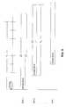
- FIG. 5is a timing diagram for access burst transmission
- FIG. 6illustrates common packet channel access burst of FIG. 5 using a common control downlink channel
- FIG. 7illustrates common packet channel access of FIG. 5 using a dedicated downlink channel
- FIG. 8shows the structure of the preamble
- FIG. 9illustrates preamble and pilot formats
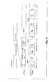
- FIG. 10is a common packet channel timing diagram and frame format of the down link common control link.
- FIG. 11illustrates frame format of common packet channel, packet data.
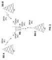
- the common-packet channelis a new and novel uplink transport channel for transmitting variable size packets from a mobile station to a base station within listening range, without the need to obtain a two way link with any one or set of base stations.
- the channel resource allocationis contention based; that is, a number of mobile stations could at any time contend for the same resources, as found in an ALOHA system.
- common-packet channelprovides an improvement to a code-division-multiple-access (CDMA) system employing spread-spectrum modulation.
- the CDMA systemhas a plurality of base stations (BS) 31 , 32 , 33 and a plurality of remote stations (RS).
- Each remote station 35has an RS-spread-spectrum transmitter and an RS-spread-spectrum receiver.
- An uplinkis from the remote station 35 to a base station 31 .
- the uplinkhas the common-packet channel (CPCH).
- a downlinkis from a base station 31 to the remote station 35 , and is denoted a common-control channel (CCCH).
- the common-control channelhas common signaling used by the plurality of remote stations.
- DPCHdownlink dedicated physical channel
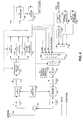
- a BS spread-spectrum transmitter and a BS spread-spectrum receiveris shown.
- the BS spread-spectrum transmitter and the BS spread-spectrum receiverare located at the base station 31 .
- the BS spread-spectrum receiverincludes an antenna 309 coupled to a circulator 310 , a receiver radio frequency (RF) section 311 , a local oscillator 313 , a quadrature demodulator 312 , and an analog-to-digital converter 314 .
- the receiver RF section 311is coupled between the circulator 310 and the quadrature demodulator 312 .
- the quadrature demodulatoris coupled to the local oscillator 313 and to the analog to digital converter 314 .
- the output of the analog-to-digital converter 315is coupled to a programmable-matched filter 315 .
- a preamble processor 316 , pilot processor 317 and data-and-control processor 318are coupled to the programmable-matched filter 315 .
- a controller 319is coupled to the preamble processor 316 , pilot processor 317 and data-and-control processor 318 .
- a de-interleaver 320is coupled between the controller 319 and a forward-error-correction (FEC) decoder 321 .
- FECforward-error-correction
- the BS spread-spectrum transmitterincludes a forward-error-correction (FEC) encoder 322 coupled to an interleaver 323 .
- a packet formatter 324is coupled to the interleaver 323 and to the controller 319 .
- a variable gain device 325is coupled between the packet formatter 324 and a product device 326 .
- a spreading-sequence generator 327is coupled to the product device 326 .
- a digital-to-analog converter 328is coupled between the product device 328 and quadrature modulator 329 .
- the quadrature modulator 329is coupled to the local oscillator 313 and a transmitter RF section 330 .
- the transmitter RF section 330is coupled to the circulator 310 .
- the controller 319has control links coupled to the analog-to-digital converter 314 , programmable-matched filter 315 , preamble processor 316 , the digital-to-analog converter 328 , the spreading sequence generator 327 , the variable gain device 325 , the packet formatter 324 , the de-interleaver 320 , the FEC decoder 321 , the interleaver 323 and the FEC encoder 322 .
- a received spread-spectrum signal from antenna 309passes through circulator 310 and is amplified and filtered by receiver RF section 311 .
- the local oscillator 313generates a local signal which quadrature demodulator 312 uses to demodulator in-phase and quadrature phase components of the received spread-spectrum signal.
- the analog-to-digital converter 314converts the in-phase component and the quadrature-phase component to a digital signal.
- the programmable-matched filter 315despreads the received spread-spectrum signal.
- a correlatoras an alternative, may be used as an equivalent means for despreading the received spread-spectrum signal.
- the preamble processor 316detects the preamble portion of the received spread-spectrum signal.
- the pilot processordetects and synchronizes to the pilot portion of the received spread-spectrum signal.
- the data and control processordetects and processes the data portion of the received spread-spectrum signal. Detected data passes through the controller 319 to the de-interleaver 320 and FEC decoder 321 . Data and signaling are outputted from the FEC decoder 321 .
- dataare FEC encoded by FEC encoder 322 , and interleaved by interleaver 323 .
- the packet formatterformats data, signaling, acknowledgment signal, collision detection signal, pilot signal and transmitting power control (TPC) signal into a packet.
- the packetis outputted from packet formatter, and the packet level is amplified or attenuated by variable gain device 325 .
- the packetis spread-spectrum processed by product device 326 , with a spreading chip-sequence from spreading-sequence generator 327 .
- the packetis converted to an analog signal by digital-to-analog converter 328 , and in-phase and quadrature-phase components are generated by quadrature modulator 329 using a signal from local oscillator 313 .
- the packetis translated to a carrier frequency, filtered and amplified by transmitter RF section 330 , and then passes through circulator 310 and is radiated by antenna 309 .
- the RS spread-spectrum transmitter and the RS spread-spectrum receiverare located at the remote station 35 , shown in FIG. 1 .
- the RS spread-spectrum receiverincludes an antenna 409 coupled to a circulator 410 , a receiver radio frequency (RF) section 411 , a local oscillator 413 , a quadrature demodulator 412 , and an analog-to-digital converter 414 .
- the receiver RF section 411is coupled between the circulator 410 and the quadrature demodulator 412 .
- the quadrature demodulatoris coupled to the local oscillator 413 and to the analog to digital converter 414 .
- the output of the analog-to-digital converter 415is coupled to a programmable-matched filter 415 .
- An acknowledgment detector 416 , pilot processor 417 and data-and-control processor 418are coupled to the programmable-matched filter 415 .
- a controller 419is coupled to the acknowledgment detector 416 , pilot processor 417 and data-and-control processor 418 .
- a de-interleaver 420is coupled between the controller 419 and a forward-error-correction (FEC) decoder 421 .
- FECforward-error-correction
- the RS spread-spectrum transmitterincludes a forward-error-correction (FEC) encoder 422 coupled to an interleaver 423 .
- a packet formatter 424is coupled through a multiplexer 451 to the interleaver 423 and to the controller 419 .
- a preamble generator 452 and a pilot generator 453 for the preambleare coupled to the multiplexer 451 .
- a variable gain device 425is coupled between the packet formatter 424 and a product device 426 .
- a spreading-sequence generator 427is coupled to the product device 426 .
- a digital-to-analog converter 428is coupled between the product device 428 and quadrature modulator 429 .
- the quadrature modulator 429is coupled to the local oscillator 413 and a transmitter RF section 430 .
- the transmitter RF section 430is coupled to the circulator 410 .
- the controller 419has control links coupled to the analog-to-digital converter 414 , programmable-matched filter 415 , acknowledgment detector 416 , the digital-to-analog converter 428 , the spreading sequence generator 427 , the variable gain device 425 , the packet formatter 424 , the de-interleaver 420 , the FEC decoder 421 , the interleaver 423 , the FEC encoder 422 , the preamble generator 452 and the pilot generator 453 .
- a received spread-spectrum signal from antenna 409passes through circulator 410 and is amplified and filtered by receiver RF section 411 .
- the local oscillator 413generates a local signal which quadrature demodulator 412 uses to demodulate in-phase and quadrature phase components of the received spread-spectrum signal.
- the analog-to-digital converter 414converts the in-phase component and the quadrature-phase component to a digital signal.
- the programmable-matched filter 415despreads the received spread-spectrum signal.
- a correlatoras an alternative, may be used as an equivalent means for despreading the received spread-spectrum signal.
- the acknowledgment detector 416detects the acknowledgment in the received spread-spectrum signal.
- the pilot processordetects and synchronizes to the pilot portion of the received spread-spectrum signal.
- the data and control processordetects and processes the data portion of the received spread-spectrum signal. Detected data passes through the controller 419 to the de-interleaver 420 and FEC decoder 421 . Data and signaling are outputted from the FEC decoder 421 .
- dataare FEC encoded by FEC encoder 422 , and interleaved by interleaver 423 .
- the preamble generator 452generates a preamble and the pilot generator 453 generates a pilot for the preamble.
- the multiplexer 451multiplexes the data, preamble and pilot, and the packet formatter 424 formats the preamble, pilot and data into a common-packet channel packet. Further, the packet formatter formats data, signaling, acknowledgment signal, collision detection signal, pilot signal and TPC signal into a packet.
- the packetis outputted from packet formatter, and the packet level is amplified or attenuated by variable gain device 425 .
- the packetis spread-spectrum processed by product device 426 , with s spreading chip-sequence from spreading-sequence generator 427 .
- the packetis converted to an analog signal by digital-to-analog converter 428 , and in-phase and quadrature-phase components are generated by quadrature modulator 429 using a signal from local oscillator 413 .
- the base stationtransmits a common-synchronization channel, which has a frame time duration T F .
- the common-synchronization channelhas a common chip-sequence signal, which is common to the plurality of remote stations communicating with the particular base station.
- the time T F of one frameis ten milliseconds.
- Within one framethere are eight access slots. Each access slot lasts 1.25 milliseconds.
- Timing for the access slotsis the frame timing, and the portion of the common-synchronization channel with the frame timing is denoted the frame-timing signal.
- the frame-timing signalis the timing a remote station uses in selecting an access slot in which to transmit an access-burst signal.
- a first remote station attempting to access the base stationhas a first RS-spread-spectrum receiver for receiving the common synchronization channel, broadcast from the base station.
- the first RS-spread-spectrum receiverdetermines frame timing from the frame-timing signal.
- a first RS-spread-spectrum transmitterlocated at the first remote station, transmits an access-burst signal.
- An access burst signalstarts at the beginning of an access slot, as defined by the frame timing portion of the common-synchronization channel.
- FIG. 6illustratively shows the common-packet channel access burst format, for each access-burst signal.
- Each access-burst signalhas a plurality of segments.
- Each segmenthas a preamble followed by a pilot signal.
- the plurality of segmentshas a plurality of power levels, respectively. More particularly, the power level of each segment increases with each subsequent segment.
- a first segmenthas a first preamble and pilot, at a first power level P 0 .
- a second segmenthas a second preamble and a second pilot, at a second power level P 1 .
- the third segmenthas a third preamble and a third pilot at a third power level P 2 .
- the first preamble, the second preamble, the third preamble, and subsequent preamblesmay be identical or different.
- the power level of the pilotpreferably is less than the power level of the preamble.
- a preambleis for synchronization, and a corresponding pilot, which follows a preamble, is to keep the BS spread-spectrum receiver receiving the spread-spectrum signal from the remote station, once a preamble is detected.
- a subsequent increase or decrease of power levelsis basically a closed loop power control system.
- the preambleis generated by preamble generator 452 and the pilot is generated by pilot generator 453 .
- a preamble formatis shown in FIG. 8 .
- the preamble format with a pilotis shown in FIG. 9 .
- the multiplexer 451with timing from the controller 419 , selects the preamble then a corresponding pilot, for packet formatter 424 .
- a series of preambles and pilotsmay be generated and made as part of the packet by packet formatter 424 .
- the preambles and pilotscan have their power level adjusted either in the preamble generator 452 and pilot generator 453 , or by the variable gain device 425 .
- the BS spread-spectrum receiverreceives the access-burst signal at a detected-power level. More particularly, the access-burst signal has the plurality of preambles at a plurality of power levels, respectively.
- an acknowledgment (ACK) signalis transmitted from the BS spread-spectrum transmitter.
- the ACK signalis shown in FIG. 6, in response to the fourth preamble having sufficient power for detection by the BS spread-spectrum receiver.
- FIG. 3shows the preamble processor 316 for detecting the preamble and the pilot processor 317 for continuing to receive the packet after detecting the preamble.
- the processor 319Upon detecting the preamble, the processor 319 initiates an ACK signal which passes to packet formatter 324 and is radiated by the BS spread-spectrum transmitter.
- the first RS-spread-spectrum receiverreceives the acknowledgment signal.
- the first RS-spread-spectrum transmittertransmits to the BS-spread-spectrum receiver, a spread-spectrum signal having data.
- the datais shown in FIG. 6, in time, after the ACK signal.
- the dataincludes a collision detection (CD) portion of the signal, referred to herein as a collision detection signal, and message.
- CDcollision detection
- the BS receiverIn response to each packet transmitted from the RS spread-spectrum transmitter, the BS receiver detects the collision detection portion of the data, and retransmits the data field of the collision detection portion of the data to the remote station.
- FIG. 10shows the timing diagram for re-transmitting the collision detection field.
- FIG. 11shows a frame format of a common-packet channel data payload.
- a remote stationupon power up searches for transmission from nearby base stations.
- the Remote stationUpon successful synchronization with one or more base stations, the Remote station receives the necessary system parameters from a continuously transmitted by all base stations broadcast control channel (BCCH).
- BCCHbroadcast control channel
- the remote stationcan determine various parameters required when first transmitting to a base station. Parameters of interest are the loading of all the base station in the vicinity of the remote station, their antenna characteristics, spreading codes used to spread the downlink transmitted information, timing information and other control information. With this information, the remote station can transmit specific waveforms in order to capture the attention of a nearby base station.
- the remote stationIn the common packet channel the remote station, having all the necessary information from the nearby base station, it starts transmitting a particular preamble from a set of predefined preambles, at a well selected time intervals.
- the particular structure of the preamble waveformsis selected on the basis that detection of the preamble waveform at the base station is to be as easy as possible with minimal loss in detectability.
- the physical common packet channel(CPCH) is used to carry the CPCH. It is based on the well known Slotted ALOHA approach. There is a number of well defined time offsets relative to the frame boundary of a downlink received BCCH channel. These time offsets define access slots. The number of access slots is chosen according to the particular application at hand. As an example, shown in FIG. 5, eight access slots are spaced 1.25 msec apart in a frame of 10-msec duration.
- a remote stationpicks an access slot in a random fashion and tries to obtain a connection with a base station by transmitting a preamble waveform.
- the base stationis able to recognize this preamble, and is expecting its reception at the beginning of each access slot.
- the length of the access burstis variable and the length of the access burst is allowed to vary from a few access slots to many frame durations.
- the amount of data transmitted by the remote stationcould depend on various factors. Some of those are: class capability of the remote station, prioritization, the control information transmitted down by the base station, and various bandwidth management protocols residing and executed at the base station.
- a field at the beginning of the data portionsignifies the length of the data.
- the structure of the access burstis shown in FIG. 6 .
- the access burststarts with a set of preambles of duration T P whose power is increased in time from preamble to preamble in a step-wise manner.
- the transmitted power during each preambleis constant.
- the access burstconsists of a pilot signal transmitted at a fixed power level ratio relative to the previously transmitted preamble.
- the pilot signalcould be eliminated by setting it to a zero power level.
- the transmission of the preamblesceases because either the preamble has been picked up, detected, by the base station, and the base station has responded to the remote station with a layer one acknowledgment L 1 ACK which the remote station has also successfully received. Transmission of the preamble ceases also if the remote station has transmitted the maximum allowed number of preambles M P . Upon receiving this L 1 ACK the remote station starts transmission of its data. Once the remote station has transmitted more than M P preambles, it undergoes a forced random back off procedure. This procedure forces the remote station to delay its access burst transmission for a later time. The random back off procedure could be parameterized based on the priority statues of the Remote station.
- the amount by which the power is increased from preamble to preambleis D P which is either fixed for all cells at all times or it is repeatedly broadcast via the BCCH.
- D PThe amount by which the power is increased from preamble to preamble.
- Remote stations with different priority statuscould use a power increase which depends on a priority status assigned to the remote station.
- the priority statuscould be either predetermined or assigned to the remote station after negotiation with the base station.
- the preferred approachis to use different codes rather than a single repeating code in generating each preamble.
- L possible codesnot necessarily Gold Codes
- a 0 , A 1 , . . . A L ⁇ 1possible preambles will be as shown in FIG. 8 .
- the order of the A i 'scan be chosen so that identical codes are not used in the same locations for two different preambles.
- a similar approachcould be used to form the pilot signals.
- the downlink common control channel structure for even and odd slotsis shown.
- the even slotscontain reference data and control data.
- the pilot symbolsare used to derive a reference for demodulating the remaining control symbols.
- the control symbolsare made of transport frame indicator (TFI) symbols, power control (PC) symbols, collision detection (CD) symbol and signaling symbols (SIG).
- the odd slotscontain all the information that the even slots contain plus an acknowledgment (ACK) signal. Odd slots do not include collision detection fields.
- the uplink CPCHis shown over the last transmitted preamble. After the last transmitted preamble, the base station has successfully detected the transmission of the last transmitted preamble and transmits back the acknowledgment signal. During the same time, the remote station is tuned to receive the ACK signal. The ACK signal transmitted corresponds to the specific preamble structure transmitted on the uplink. Once the remote station detects the ACK signal corresponding to transmitted preamble by the remote station, the remote station begins transmission of its data.
- FIG. 11shows the structure of the uplink frame and the slot format for the data portion of the uplink transmission.
- Data and control informationis transmitted in an in-phase and quadrature-phase multiplexed format. That is, the data portion could be transmitted on the in-phase coordinate and the control portion on the quadrature-phase coordinate.
- the modulation for the data and controlis BPSK.
- the control channelcontains the information for the receiver to enable the demodulation of the data.
- the control channelprovides for upper layer system functionality.
- the data portionconsists of one or more frames. Each frame consists of a number of slots. As an example the frame duration could be 10 milliseconds long and the slot duration 0.625 milliseconds long. In that case, there are 16 slots per frame.
- the beginning of the data payloadcontains a collision detection field used to relay information about the possibility of collision with other simultaneously transmitting remote stations. The collision detection field is read by the base station. The base station expects the presence of the collision detection field since it had provided an ACK signal at the last time slot.
- the collision detection fieldincludes a temporary identification (ID) number chosen at random by the mobile for the transmission of the current packet.
- IDtemporary identification
- the base stationreads the collision detection field and reflects, or transmits back, the collision detection field on the downlink. If the collision detection field detected by the remote station matched the one just being transmitted by the same remote station, then the collision detection field is an identification that the transmission is being received correctly. The remote station then continues transmitting the remaining of the packet. In case the collision detection field has not been received correctly by the remote station, then the remote station considers the packet reception by the base station as erroneous and discontinues transmission of the remaining packet.
- the function of the remaining fieldsare as follows.
- the Pilot fieldenables the demodulation of both the data and control bits.
- the transmitted power control (TPC) bitsare used to control the power of a corresponding downlink channel, in case a down link channel directed to the same user is operational. If the downlink channel were not operational, then the TPC control bits can be used to relay additional pilot bits instead.
- the Rate Information (RI) fieldis used to provide the transmitter with the ability to change its data rate without the necessity to explicitly negotiate the instantaneous data rate with the base station.
- the service fieldprovides information of the particular service the data bits are to be used for.
- the length fieldspecifies the time duration of the packet.
- the signal fieldcan be used to provide additional control information as required.
- Additional functionalities of the common packet channelare: (1) bandwidth management and (2) L 2 acknowledgment mechanism.
- the bandwidth management functionalityis implemented via signaling information on the down link common control channel.
- the firstrelies on changing the priority status of all uplink users, which currently are transmitting information using the CPCH.
- all the usersare remapping their priority status via a control signal sent at the downlink.
- the priority of the CPCH usersis lowered their ability to capture an uplink channel is lowered.
- the other mechanismis for the base station to relay the maximum possible data rate the CPCH users are allowed to transmit.
- the base stationcould provide a negative acknowledgment through the ACK signal. In this case, any remote station which is tuned to receive the ACK signal is prohibited from further transmission of an access-burst signal.
- the L 2 acknowledgment (L 2 ACK) mechanismwhich is different than the L 1 ACK, is used by the base station to notify the remote station for the correctness of an uplink packet reception.
- the base stationcould either relay to the remote station which portions of the packet have been received correctly or which have been received incorrectly.
- the packetcould be identified as consisting of a number of frames, with each frame consisting of a number of sub-frames. The frames are identified by a predetermined number. The sub-frames in each frame are also identified by a specific number.
- One way for the base to relay the information about the correctness of the packetis to identify all the frames and sub-frames that have been received correctly.
- Another wayis to identify the frames and sub-frames that have been received in error.
- the way the base station could identify the correctness of a frame or sub-frameis by checking its cyclic residue code (CRC) field.
- CRCcyclic residue code
- Other more robust mechanisms for acknowledgmentmay be used.
- a negative acknowledgmentmay be part of the common packet channel.
- the base stationcould send a negative acknowledgment (ACK), as part of the L 1 ACK, in order to force the remote station from transmitting the message part.
- ACKnegative acknowledgment
- the base stationtransmits a broadcast common synchronization channel.
- This broadcast common synchronization channelincludes a frame timing signal.
- the remote stationsextract the frame timing transmitted by the base station by receiving the broadcast common synchronization channel.
- the frame timingis used by the remote stations to derive a timing schedule by dividing the frame duration in a number of access slots.
- the remote stationsare allowed to transmit their preambles only at the beginning of each access slot. The actual transmit times for different remote stations could be slightly different due to their different propagation delays.
- Each remote stationrepeatedly transmits its preamble signal until the base station detects the preamble, acknowledges that the preamble is received, and the acknowledgment is correctly received by the remote station. There could be more than one remote station transmitting the same preamble signal in the same access slot. The base station cannot recognize if two or more remote stations were transmitting the same preamble in the same access slot. When the base station detects the transmission of a preamble signal, it transmits back an acknowledgment message. There is one acknowledgment message corresponding to each possible preamble signal. Therefore, the are as many acknowledgment messages as there are preamble signals.
- Each remote stationincludes a collision detection (CD) field in the beginning of the transmitted message.
- the CD fieldis chosen at random by each remote station and independently from each other Remote Station. There is a predefined limited number of CD fields. Two remote stations transmitting their message at the same time most likely chose a different CD field.
- the base stationreceives the CD field, the base station reflects back, transmits back, the CD field to the remote station.
- the remote stationreads the reflected CD field by the base station. If the reflected CD field matched the CD field the remote station transmitted, the remote station assumes that the remote station is being received correctly by the base station and continues transmitting the rest of the message, or data. If the reflected CD field from the base station did not match the one transmitted by the remote station, then the remote station assumes that there has been a collision and stops transmitting the remaining message or data.
Landscapes
- Engineering & Computer Science (AREA)
- Computer Networks & Wireless Communication (AREA)
- Signal Processing (AREA)
- Mobile Radio Communication Systems (AREA)
Abstract
Description
Claims (16)
Priority Applications (3)
| Application Number | Priority Date | Filing Date | Title |
|---|---|---|---|
| US09/679,367US6301286B1 (en) | 1999-03-22 | 2000-10-05 | Common packet channel |
| US09/941,756US6717975B2 (en) | 1999-03-22 | 2001-08-30 | Common packet channel |
| US10/667,665US6996155B2 (en) | 1999-03-22 | 2003-09-23 | Common packet channel |
Applications Claiming Priority (2)
| Application Number | Priority Date | Filing Date | Title |
|---|---|---|---|
| US09/273,508US6169759B1 (en) | 1999-03-22 | 1999-03-22 | Common packet channel |
| US09/679,367US6301286B1 (en) | 1999-03-22 | 2000-10-05 | Common packet channel |
Related Parent Applications (1)
| Application Number | Title | Priority Date | Filing Date |
|---|---|---|---|
| US09/273,508ContinuationUS6169759B1 (en) | 1999-03-22 | 1999-03-22 | Common packet channel |
Related Child Applications (1)
| Application Number | Title | Priority Date | Filing Date |
|---|---|---|---|
| US09/941,756ContinuationUS6717975B2 (en) | 1999-03-22 | 2001-08-30 | Common packet channel |
Publications (1)
| Publication Number | Publication Date |
|---|---|
| US6301286B1true US6301286B1 (en) | 2001-10-09 |
Family
ID=23044226
Family Applications (7)
| Application Number | Title | Priority Date | Filing Date |
|---|---|---|---|
| US09/273,508Expired - LifetimeUS6169759B1 (en) | 1999-03-22 | 1999-03-22 | Common packet channel |
| US09/275,010Expired - LifetimeUS6389056B1 (en) | 1999-03-22 | 1999-03-24 | Pre-data power control common packet channel |
| US09/679,367Expired - Fee RelatedUS6301286B1 (en) | 1999-03-22 | 2000-10-05 | Common packet channel |
| US09/941,756Expired - LifetimeUS6717975B2 (en) | 1999-03-22 | 2001-08-30 | Common packet channel |
| US10/096,312Expired - LifetimeUS6639936B2 (en) | 1999-03-22 | 2002-03-13 | Pre-data power control common packet channel |
| US10/649,816Expired - LifetimeUS7046717B2 (en) | 1999-03-22 | 2003-08-28 | Pre-data power control common packet channel |
| US10/667,665Expired - LifetimeUS6996155B2 (en) | 1999-03-22 | 2003-09-23 | Common packet channel |
Family Applications Before (2)
| Application Number | Title | Priority Date | Filing Date |
|---|---|---|---|
| US09/273,508Expired - LifetimeUS6169759B1 (en) | 1999-03-22 | 1999-03-22 | Common packet channel |
| US09/275,010Expired - LifetimeUS6389056B1 (en) | 1999-03-22 | 1999-03-24 | Pre-data power control common packet channel |
Family Applications After (4)
| Application Number | Title | Priority Date | Filing Date |
|---|---|---|---|
| US09/941,756Expired - LifetimeUS6717975B2 (en) | 1999-03-22 | 2001-08-30 | Common packet channel |
| US10/096,312Expired - LifetimeUS6639936B2 (en) | 1999-03-22 | 2002-03-13 | Pre-data power control common packet channel |
| US10/649,816Expired - LifetimeUS7046717B2 (en) | 1999-03-22 | 2003-08-28 | Pre-data power control common packet channel |
| US10/667,665Expired - LifetimeUS6996155B2 (en) | 1999-03-22 | 2003-09-23 | Common packet channel |
Country Status (4)
| Country | Link |
|---|---|
| US (7) | US6169759B1 (en) |
| AR (1) | AR023126A1 (en) |
| CA (1) | CA2627033C (en) |
| ZA (1) | ZA200107739B (en) |
Cited By (28)
| Publication number | Priority date | Publication date | Assignee | Title |
|---|---|---|---|---|
| US20010026543A1 (en)* | 2000-02-16 | 2001-10-04 | Samsung Electronics Co.,Ltd. | Apparatus and method for assigning a common packet channel in a CDMA communication system |
| WO2002032017A1 (en)* | 2000-10-11 | 2002-04-18 | Samsung Electronics Co., Ltd. | Apparatus and method for controlling transmit antenna array for physical downlink shared channel in a mobile communication system |
| US20020101839A1 (en)* | 2001-02-01 | 2002-08-01 | Tantivy Communications, Inc. | Alternate channel for carrying selected message types |
| US6574267B1 (en) | 1999-03-22 | 2003-06-03 | Golden Bridge Technology, Inc. | Rach ramp-up acknowledgement |
| US6606341B1 (en) | 1999-03-22 | 2003-08-12 | Golden Bridge Technology, Inc. | Common packet channel with firm handoff |
| US6639936B2 (en) | 1999-03-22 | 2003-10-28 | Golden Bridge Technology, Inc. | Pre-data power control common packet channel |
| US6643318B1 (en) | 1999-10-26 | 2003-11-04 | Golden Bridge Technology Incorporated | Hybrid DSMA/CDMA (digital sense multiple access/code division multiple access) method with collision resolution for packet communications |
| US20030223452A1 (en)* | 2002-05-29 | 2003-12-04 | Nokia Corporation | System and method for random access channel capture with automatic retransmission request |
| US20040203968A1 (en)* | 2002-06-28 | 2004-10-14 | Nandu Gopalakrishnan | Method of uplink scheduling for data communication |
| US20040264550A1 (en)* | 1999-06-11 | 2004-12-30 | Dabak Anand G. | Random access preamble coding for initiation of wireless mobile communications sessions |
| US20050180324A1 (en)* | 2004-02-13 | 2005-08-18 | Kari Niemela | Method of controlling data transmission, radio system, packet control unit, and base station |
| US20050180325A1 (en)* | 2004-02-13 | 2005-08-18 | Nokia Corporation | Method of controlling data transmission, radio system, packet control unit, and remote network element |
| US20060023654A1 (en)* | 2004-07-27 | 2006-02-02 | Eitan Koren | Method and apparatus for enabling interoperability between packet-switched systems |
| US20060023747A1 (en)* | 2004-07-27 | 2006-02-02 | Eitan Koren | Method and apparatus for session layer framing to enable interoperability between packet-switched systems |
| US20070050341A1 (en)* | 2005-08-23 | 2007-03-01 | Hull Jonathan J | Triggering applications for distributed action execution and use of mixed media recognition as a control input |
| US7436801B1 (en) | 2004-09-08 | 2008-10-14 | Golden Bridge Technology, Inc. | Deferred access method for uplink packet channel |
| WO2009016260A1 (en) | 2007-08-01 | 2009-02-05 | Nokia Siemens Networks Oy | Resource allocation |
| US20110010598A1 (en)* | 2007-10-05 | 2011-01-13 | Nokia Corporation | User Specific Load Balancing |
| US7936728B2 (en) | 1997-12-17 | 2011-05-03 | Tantivy Communications, Inc. | System and method for maintaining timing of synchronization messages over a reverse link of a CDMA wireless communication system |
| US20110216707A1 (en)* | 2001-02-05 | 2011-09-08 | Ipr Licensing, Inc. | Application specific traffic optimization in a wireless link |
| US8134980B2 (en) | 1998-06-01 | 2012-03-13 | Ipr Licensing, Inc. | Transmittal of heartbeat signal at a lower level than heartbeat request |
| US8139546B2 (en) | 1998-06-01 | 2012-03-20 | Ipr Licensing, Inc. | System and method for maintaining wireless channels over a reverse link of a CDMA wireless communication system |
| US8155096B1 (en) | 2000-12-01 | 2012-04-10 | Ipr Licensing Inc. | Antenna control system and method |
| US8175120B2 (en) | 2000-02-07 | 2012-05-08 | Ipr Licensing, Inc. | Minimal maintenance link to support synchronization |
| US8638877B2 (en) | 2001-02-01 | 2014-01-28 | Intel Corporation | Methods, apparatuses and systems for selective transmission of traffic data using orthogonal sequences |
| US9014118B2 (en) | 2001-06-13 | 2015-04-21 | Intel Corporation | Signaling for wireless communications |
| US9042400B2 (en) | 1997-12-17 | 2015-05-26 | Intel Corporation | Multi-detection of heartbeat to reduce error probability |
| US9525923B2 (en) | 1997-12-17 | 2016-12-20 | Intel Corporation | Multi-detection of heartbeat to reduce error probability |
Families Citing this family (123)
| Publication number | Priority date | Publication date | Assignee | Title |
|---|---|---|---|---|
| ZA931077B (en)* | 1992-03-05 | 1994-01-04 | Qualcomm Inc | Apparatus and method for reducing message collision between mobile stations simultaneously accessing a base station in a cdma cellular communications system |
| US7079523B2 (en)* | 2000-02-07 | 2006-07-18 | Ipr Licensing, Inc. | Maintenance link using active/standby request channels |
| RU2210864C2 (en)* | 1998-03-23 | 2003-08-20 | Самсунг Электроникс Ко., Лтд. | Device and method for power regulation to control return-line common-user channel in cdma communication system |
| EP0967742B1 (en)* | 1998-06-25 | 2007-03-21 | Philips Intellectual Property & Standards GmbH | Wireless Network |
| FI105961B (en)* | 1998-12-14 | 2000-10-31 | Nokia Networks Oy | Reception procedure and recipients |
| EP1311075B9 (en) | 1998-12-14 | 2012-05-02 | Interdigital Technology Corporation | Random access channel preamble detection |
| DE19901622A1 (en)* | 1999-01-18 | 2000-07-20 | Philips Corp Intellectual Pty | Wireless network |
| US6850514B1 (en)* | 2000-05-17 | 2005-02-01 | Interdigital Technology Corporation | Channel assignment in a spread spectrum CDMA communication system |
| AU4500999A (en)* | 1999-05-26 | 2000-12-18 | Nokia Corporation | Random access control method and system |
| GB9914926D0 (en)* | 1999-06-26 | 1999-08-25 | Koninkl Philips Electronics Nv | Radio communication system |
| DE19930509A1 (en)* | 1999-07-03 | 2001-01-04 | Philips Corp Intellectual Pty | Wireless network to request a collision channel |
| DE19935480A1 (en)* | 1999-07-28 | 2001-02-22 | Infineon Technologies Ag | Method for estimating the channel impulse responses of a mobile radio channel |
| DE19935997A1 (en)* | 1999-07-30 | 2001-03-01 | Siemens Ag | Method for optimizing data transmission over lines |
| GB9918130D0 (en)* | 1999-08-03 | 1999-10-06 | Koninkl Philips Electronics Nv | Radio communication system |
| CN1147204C (en)* | 1999-08-03 | 2004-04-21 | 皇家菲利浦电子有限公司 | Method and system for allocating random access channel in radio communication system |
| KR100526508B1 (en)* | 1999-08-17 | 2005-11-08 | 삼성전자주식회사 | apparatus and method for access communicating in cdma communication system |
| US7068613B1 (en)* | 1999-11-24 | 2006-06-27 | Lg Electronics Inc. | Method and apparatus for stopping data/packet transmission |
| US7061878B2 (en)* | 1999-11-24 | 2006-06-13 | Lg Electronics Inc. | Method and apparatus for stopping data/packet transmission |
| WO2001039416A1 (en) | 1999-11-29 | 2001-05-31 | Golden Bridge Technology, Inc. | Second level collision resolution for packet data communications |
| US6757319B1 (en) | 1999-11-29 | 2004-06-29 | Golden Bridge Technology Inc. | Closed loop power control for common downlink transport channels |
| ATE433274T1 (en)* | 1999-11-29 | 2009-06-15 | Samsung Electronics Co Ltd | METHOD FOR ALLOCATING A COMMON PACKET CHANNEL IN A CDMA COMMUNICATIONS SYSTEM |
| JP2001251667A (en)* | 2000-02-02 | 2001-09-14 | Lg Electronics Inc | Assignment method of common packet channel |
| US6904079B2 (en)* | 2000-02-08 | 2005-06-07 | Ipr Licensing, Inc. | Access channel structure for wireless communication system |
| EP1254533A4 (en) | 2000-02-09 | 2006-04-05 | Golden Bridge Tech Inc | Collision avoidance |
| US7079507B2 (en)* | 2000-02-25 | 2006-07-18 | Nokia Corporation | Method and apparatus for common packet channel assignment |
| FR2805688A1 (en)* | 2000-02-28 | 2001-08-31 | Mitsubishi Electric France | METHOD FOR BALANCING TRANSPORT CHANNELS WITHIN A COMPOSITE CHANNEL, CORRESPONDING BASE DEVICE AND STATION |
| DE10009401C2 (en)* | 2000-02-28 | 2003-07-24 | Siemens Ag | Method, mobile radio system and station for determining a lead time for a connection between two stations |
| US7079586B1 (en)* | 2000-03-16 | 2006-07-18 | Koninklijke Philips Electronics N.V. | Systems and methods for optimal distribution of symbols in a fixed size data packet to improve receiver performance |
| US6983012B1 (en) | 2000-08-03 | 2006-01-03 | Golden Bridge Technology Incorporated | Implementation of digital filter with reduced hardware |
| US7099629B1 (en)* | 2000-11-06 | 2006-08-29 | Qualcomm, Incorporated | Method and apparatus for adaptive transmission control in a high data rate communication system |
| US7126930B2 (en)* | 2001-02-10 | 2006-10-24 | Qualcomm, Incorporated | Method and apparatus for transmitting messages in a wireless communication system |
| US6937641B2 (en)* | 2001-02-28 | 2005-08-30 | Golden Bridge Technology, Inc. | Power-controlled random access |
| JP3583730B2 (en)* | 2001-03-26 | 2004-11-04 | 株式会社東芝 | Wireless communication system and wireless transmission device |
| KR20020081528A (en)* | 2001-04-18 | 2002-10-28 | 광주과학기술원 | The traffic control method of wireless mobile communications |
| US7826414B2 (en)* | 2001-05-07 | 2010-11-02 | Qualcomm, Incorporated | Channel allocations in a communications system |
| US7245725B1 (en)* | 2001-05-17 | 2007-07-17 | Cypress Semiconductor Corp. | Dual processor framer |
| CN1314219C (en)* | 2001-06-18 | 2007-05-02 | 皇家菲利浦电子有限公司 | Peak detection accuracy |
| US20030067961A1 (en)* | 2001-10-04 | 2003-04-10 | Hudson John E. | Wireless spread spectrum communications system, communications apparatus and method therefor |
| KR100452639B1 (en)* | 2001-10-20 | 2004-10-14 | 한국전자통신연구원 | Common Packet Channel Access Method for Mobile Satellite Communication System |
| JP4012391B2 (en)* | 2001-10-30 | 2007-11-21 | 株式会社エヌ・ティ・ティ・ドコモ | Mobile station, mobile communication system, handover control method, handover control program, and recording medium |
| US6756901B2 (en)* | 2001-12-17 | 2004-06-29 | James P Campman | Multi function electronic personal monitor and radio telemetry cell system |
| AU2003219882A1 (en)* | 2002-03-01 | 2003-09-16 | Cognio, Inc. | System and method for joint maximal ratio combining |
| US6862456B2 (en)* | 2002-03-01 | 2005-03-01 | Cognio, Inc. | Systems and methods for improving range for multicast wireless communication |
| US6785520B2 (en) | 2002-03-01 | 2004-08-31 | Cognio, Inc. | System and method for antenna diversity using equal power joint maximal ratio combining |
| US20040001448A1 (en)* | 2002-06-28 | 2004-01-01 | Preston Shawn E. | System and method for transmitting highly correlated preambles in QAM constellations |
| US20040010746A1 (en)* | 2002-07-10 | 2004-01-15 | Lucas L. Victor | Forward error correction system for wireless communications |
| DE10234424A1 (en) | 2002-07-29 | 2004-02-12 | Bayer Ag | Benzothiophene, benzofuran and indoleureas |
| DE60220727T2 (en)* | 2002-09-27 | 2008-03-06 | Telefonaktiebolaget Lm Ericsson (Publ) | ACCESS REQUEST AND ACCESS CONTROL IN A WIRELESS COMMUNICATION NETWORK |
| US8208364B2 (en)* | 2002-10-25 | 2012-06-26 | Qualcomm Incorporated | MIMO system with multiple spatial multiplexing modes |
| US8320301B2 (en) | 2002-10-25 | 2012-11-27 | Qualcomm Incorporated | MIMO WLAN system |
| US20040081131A1 (en) | 2002-10-25 | 2004-04-29 | Walton Jay Rod | OFDM communication system with multiple OFDM symbol sizes |
| US7986742B2 (en) | 2002-10-25 | 2011-07-26 | Qualcomm Incorporated | Pilots for MIMO communication system |
| US8412106B2 (en) | 2002-11-04 | 2013-04-02 | Xr Communications, Llc | Directed wireless communication |
| US7372928B1 (en) | 2002-11-15 | 2008-05-13 | Cypress Semiconductor Corporation | Method and system of cycle slip framing in a deserializer |
| KR100606008B1 (en)* | 2003-01-04 | 2006-07-26 | 삼성전자주식회사 | Device and method for transmitting / receiving reverse data retransmission in code division multiple access communication system |
| US6996763B2 (en)* | 2003-01-10 | 2006-02-07 | Qualcomm Incorporated | Operation of a forward link acknowledgement channel for the reverse link data |
| US20040160922A1 (en) | 2003-02-18 | 2004-08-19 | Sanjiv Nanda | Method and apparatus for controlling data rate of a reverse link in a communication system |
| US7286846B2 (en)* | 2003-02-18 | 2007-10-23 | Qualcomm, Incorporated | Systems and methods for performing outer loop power control in wireless communication systems |
| US7660282B2 (en) | 2003-02-18 | 2010-02-09 | Qualcomm Incorporated | Congestion control in a wireless data network |
| US8391249B2 (en)* | 2003-02-18 | 2013-03-05 | Qualcomm Incorporated | Code division multiplexing commands on a code division multiplexed channel |
| US8023950B2 (en) | 2003-02-18 | 2011-09-20 | Qualcomm Incorporated | Systems and methods for using selectable frame durations in a wireless communication system |
| US8081598B2 (en)* | 2003-02-18 | 2011-12-20 | Qualcomm Incorporated | Outer-loop power control for wireless communication systems |
| US8150407B2 (en)* | 2003-02-18 | 2012-04-03 | Qualcomm Incorporated | System and method for scheduling transmissions in a wireless communication system |
| US7155236B2 (en) | 2003-02-18 | 2006-12-26 | Qualcomm Incorporated | Scheduled and autonomous transmission and acknowledgement |
| US8705588B2 (en) | 2003-03-06 | 2014-04-22 | Qualcomm Incorporated | Systems and methods for using code space in spread-spectrum communications |
| US7215930B2 (en) | 2003-03-06 | 2007-05-08 | Qualcomm, Incorporated | Method and apparatus for providing uplink signal-to-noise ratio (SNR) estimation in a wireless communication |
| US8477592B2 (en)* | 2003-05-14 | 2013-07-02 | Qualcomm Incorporated | Interference and noise estimation in an OFDM system |
| GB2402579B (en)* | 2003-06-06 | 2005-09-14 | Roke Manor Research | A method of communication in a cellular communication system |
| US8489949B2 (en) | 2003-08-05 | 2013-07-16 | Qualcomm Incorporated | Combining grant, acknowledgement, and rate control commands |
| US7751520B1 (en)* | 2003-09-17 | 2010-07-06 | Atheros Communications, Inc. | Packet detection, synchronization, and frequency offset estimation |
| US8085806B2 (en)* | 2003-09-26 | 2011-12-27 | Agere Systems Inc. | Method and apparatus for detecting a collision in a carrier sense multiple access wireless system |
| US7620029B2 (en)* | 2003-10-09 | 2009-11-17 | Qualcomm Incorporated | Parallel cell ID acquisition in frequency division multiple access systems |
| US7321749B2 (en)* | 2003-10-09 | 2008-01-22 | Qualcomm Incorporated | Cell selection techniques for frequency division multiple access systems |
| US9473269B2 (en) | 2003-12-01 | 2016-10-18 | Qualcomm Incorporated | Method and apparatus for providing an efficient control channel structure in a wireless communication system |
| KR100929091B1 (en)* | 2004-02-14 | 2009-11-30 | 삼성전자주식회사 | Apparatus and method for transmitting control information in mobile communication system |
| US7453920B2 (en)* | 2004-03-09 | 2008-11-18 | Atc Technologies, Llc | Code synchronization in CDMA satellite wireless communications system using uplink channel detection |
| US7460624B2 (en)* | 2004-03-18 | 2008-12-02 | Motorola, Inc. | Method and system of reducing collisions in an asynchronous communication system |
| US7859985B2 (en)* | 2004-03-22 | 2010-12-28 | Texas Instruments Incorporated | Control on at least one frequency selecting data carrier frequencies |
| EP1787414B1 (en)* | 2004-06-24 | 2012-01-11 | Nortel Networks Limited | Preambles in ofdma system |
| KR100719339B1 (en)* | 2004-08-13 | 2007-05-17 | 삼성전자주식회사 | Frame Transmission and Receiving Method through Channel Estimation in Multiple Input Multiple Output Wireless Communication Systems |
| US8248938B2 (en)* | 2004-11-24 | 2012-08-21 | Qualcomm Incorporated | Preamble miss detection in transmission of multi-slot packets |
| US20060209970A1 (en)* | 2005-01-11 | 2006-09-21 | Emmanuel Kanterakis | Adaptive transmission rate communication system |
| US7333468B1 (en)* | 2005-05-16 | 2008-02-19 | Sun Microsystems, Inc. | Digital phase locked loops for packet stream rate matching and restamping |
| US8594252B2 (en)* | 2005-08-22 | 2013-11-26 | Qualcomm Incorporated | Interference cancellation for wireless communications |
| US8743909B2 (en)* | 2008-02-20 | 2014-06-03 | Qualcomm Incorporated | Frame termination |
| US9071344B2 (en) | 2005-08-22 | 2015-06-30 | Qualcomm Incorporated | Reverse link interference cancellation |
| US8630602B2 (en)* | 2005-08-22 | 2014-01-14 | Qualcomm Incorporated | Pilot interference cancellation |
| US8611305B2 (en)* | 2005-08-22 | 2013-12-17 | Qualcomm Incorporated | Interference cancellation for wireless communications |
| CN101300757B (en)* | 2005-11-04 | 2017-08-11 | 日本电气株式会社 | Radio communications system and the transmitted power control method for it |
| US8774019B2 (en)* | 2005-11-10 | 2014-07-08 | Apple Inc. | Zones for wireless networks with relays |
| TWI288545B (en)* | 2005-12-09 | 2007-10-11 | Chung Shan Inst Of Science | MIMO-CDMA apparatus and the coding/decoding method thereof |
| RU2421911C2 (en) | 2005-12-23 | 2011-06-20 | Эл Джи Электроникс Инк. | Method and procedures of non-synchronised connection, synchronised connection and connection synchronisation in stand-by mode and in e-utra systems |
| KR20090025281A (en)* | 2006-06-19 | 2009-03-10 | 가부시키가이샤 엔티티 도코모 | Base station and method |
| US8369860B2 (en) | 2006-08-18 | 2013-02-05 | Interdigital Technology Corporation | Sending and reducing uplink feedback signaling for transmission of MBMS data |
| CA2666955C (en) | 2006-10-25 | 2014-12-09 | Samsung Electronics Co., Ltd. | Method and apparatus for allocating radio resource using random access procedure in a mobile communication system |
| JP5317223B2 (en)* | 2007-05-16 | 2013-10-16 | トムソン ライセンシング | Method and apparatus for encoding and decoding signals |
| US8175065B2 (en)* | 2007-08-24 | 2012-05-08 | Lg Electronics Inc. | Digital broadcasting system and method of processing data in the digital broadcasting system |
| MX2010004147A (en)* | 2007-10-15 | 2010-08-09 | Thomson Licensing | High definition television transmission with mobile capability. |
| CA2701640C (en)* | 2007-10-15 | 2016-09-27 | Thomson Licensing | Apparatus and method for communicating burst mode activity |
| US8477830B2 (en) | 2008-03-18 | 2013-07-02 | On-Ramp Wireless, Inc. | Light monitoring system using a random phase multiple access system |
| US8520721B2 (en) | 2008-03-18 | 2013-08-27 | On-Ramp Wireless, Inc. | RSSI measurement mechanism in the presence of pulsed jammers |
| US20100195553A1 (en)* | 2008-03-18 | 2010-08-05 | Myers Theodore J | Controlling power in a spread spectrum system |
| US8958460B2 (en) | 2008-03-18 | 2015-02-17 | On-Ramp Wireless, Inc. | Forward error correction media access control system |
| US7593383B1 (en)* | 2008-03-18 | 2009-09-22 | On-Ramp Wireless, Inc. | Uplink transmitter in a random phase multiple access communication system |
| US7773664B2 (en)* | 2008-03-18 | 2010-08-10 | On-Ramp Wireless, Inc. | Random phase multiple access system with meshing |
| US7733945B2 (en)* | 2008-03-18 | 2010-06-08 | On-Ramp Wireless, Inc. | Spread spectrum with doppler optimization |
| US20090239550A1 (en)* | 2008-03-18 | 2009-09-24 | Myers Theodore J | Random phase multiple access system with location tracking |
| US8995417B2 (en)* | 2008-06-09 | 2015-03-31 | Qualcomm Incorporated | Increasing capacity in wireless communication |
| US9237515B2 (en)* | 2008-08-01 | 2016-01-12 | Qualcomm Incorporated | Successive detection and cancellation for cell pilot detection |
| US9277487B2 (en) | 2008-08-01 | 2016-03-01 | Qualcomm Incorporated | Cell detection with interference cancellation |
| CN101686466B (en)* | 2008-09-28 | 2012-11-21 | 华为技术有限公司 | Method, device and system of subchannel sharing |
| US20100097955A1 (en)* | 2008-10-16 | 2010-04-22 | Qualcomm Incorporated | Rate determination |
| US8811300B2 (en) | 2008-12-31 | 2014-08-19 | Mediatek Inc. | Physical structure and sequence design of midamble in OFDMA systems |
| US8363699B2 (en) | 2009-03-20 | 2013-01-29 | On-Ramp Wireless, Inc. | Random timing offset determination |
| US7639726B1 (en)* | 2009-03-20 | 2009-12-29 | On-Ramp Wireless, Inc. | Downlink communication |
| US7702290B1 (en) | 2009-04-08 | 2010-04-20 | On-Ramp Wirless, Inc. | Dynamic energy control |
| US9160577B2 (en)* | 2009-04-30 | 2015-10-13 | Qualcomm Incorporated | Hybrid SAIC receiver |
| US8787509B2 (en)* | 2009-06-04 | 2014-07-22 | Qualcomm Incorporated | Iterative interference cancellation receiver |
| US8831149B2 (en)* | 2009-09-03 | 2014-09-09 | Qualcomm Incorporated | Symbol estimation methods and apparatuses |
| JP2013512593A (en) | 2009-11-27 | 2013-04-11 | クゥアルコム・インコーポレイテッド | Capacity increase in wireless communication |
| US9509452B2 (en) | 2009-11-27 | 2016-11-29 | Qualcomm Incorporated | Increasing capacity in wireless communications |
| US20150365982A1 (en)* | 2014-06-13 | 2015-12-17 | Sony Corporation | Massive mimo link setup |
| EP3002884B1 (en)* | 2014-09-30 | 2018-04-18 | Semtech Corporation | Wireless communication method |
Citations (32)
| Publication number | Priority date | Publication date | Assignee | Title |
|---|---|---|---|---|
| US5103459A (en) | 1990-06-25 | 1992-04-07 | Qualcomm Incorporated | System and method for generating signal waveforms in a cdma cellular telephone system |
| US5280472A (en) | 1990-12-07 | 1994-01-18 | Qualcomm Incorporated | CDMA microcellular telephone system and distributed antenna system therefor |
| US5305308A (en)* | 1991-07-09 | 1994-04-19 | At&T Bell Laboratories | Wireless access telephone-to-telephone network interface architecture |
| US5329550A (en) | 1990-11-15 | 1994-07-12 | Alcatel Radiotelephone | Signal processing circuit for the European digital cellular radio system |
| US5384777A (en) | 1993-04-19 | 1995-01-24 | International Business Machines Corporation | Adaptive medium access control scheme for wireless LAN |
| US5461639A (en) | 1993-11-22 | 1995-10-24 | Qualcomm Incorporated | Fast forward link power control in a code division multiple access system |
| US5537397A (en) | 1994-06-07 | 1996-07-16 | Aloha Networks, Inc. | Spread aloha CDMA data communications |
| US5544196A (en) | 1992-03-05 | 1996-08-06 | Qualcomm Incorporated | Apparatus and method for reducing message collision between mobile stations simultaneously accessing a base station in a CDMA cellular communications system |
| US5600754A (en)* | 1992-01-28 | 1997-02-04 | Qualcomm Incorporated | Method and system for the arrangement of vocoder data for the masking of transmission channel induced errors |
| US5673259A (en) | 1995-05-17 | 1997-09-30 | Qualcomm Incorporated | Random access communications channel for data services |
| US5802465A (en) | 1993-09-06 | 1998-09-01 | Nokia Mobile Phones Ltd. | Data transmission in a radio telephone network |
| US5825835A (en) | 1996-02-23 | 1998-10-20 | L-3 Communications Corporation | Multi-user acquisition procedure for multipoint-to-point synchronous CDMA systems |
| US5850602A (en) | 1995-08-15 | 1998-12-15 | Tisdale; William R. | Communication protocol for mobile earth terminal communication device used in mobile satellite communication system |
| US5875182A (en) | 1997-01-16 | 1999-02-23 | Lockheed Martin Corporation | Enhanced access burst for random access channels in TDMA mobile satellite system |
| US5893036A (en) | 1997-01-30 | 1999-04-06 | Motorola, Inc. | Transmission power control method |
| US5894472A (en) | 1994-05-10 | 1999-04-13 | Alcatel Alsthom Compagnie Generale D'electricite | Packet access method in a cellular digital radio-communications system |
| US5933777A (en) | 1997-04-24 | 1999-08-03 | Telefonaktiebolaget Lm Ericsson (Publ) | System and method for allocating channel elements in a code division multiple access radio telecommunications network |
| US5943327A (en) | 1995-10-23 | 1999-08-24 | Siemens Aktiengesellschaft | Method and arrangement for transmitting data between a cellularly constructed mobile radiotelephone network and a mobile subscriber station |
| US5953369A (en) | 1996-06-10 | 1999-09-14 | Nec Corporation | DS-CDMA receiver with multi-stage serial interference cancelers using power level information appended to data blocks |
| US5982763A (en) | 1996-07-15 | 1999-11-09 | Nec Corporation | Reception timing detection circuit of CDMA receiver and detection method |
| US5991308A (en) | 1995-08-25 | 1999-11-23 | Terayon Communication Systems, Inc. | Lower overhead method for data transmission using ATM and SCDMA over hybrid fiber coax cable plant |
| US6009089A (en) | 1996-08-20 | 1999-12-28 | Lucent Technologies Inc. | Pilot interference cancellation for a coherent wireless code division multiple access receiver |
| US6011788A (en) | 1997-12-10 | 2000-01-04 | L-3 Communications Corporation | S-CDMA fixed wireless loop system employing subscriber unit/radio base unit super-frame alignment |
| US6026081A (en) | 1996-07-05 | 2000-02-15 | Nec Corporation | Method of controlling power on forward link in a cellular |
| US6031832A (en) | 1996-11-27 | 2000-02-29 | Telefonaktiebolaget L M Ericsson (Publ) | Method and apparatus for improving performance of a packet communications system |
| US6038223A (en) | 1997-10-22 | 2000-03-14 | Telefonaktiebolaget Lm Ericsson (Publ) | Access scheme for packet data in a digital cellular communication system |
| US6038250A (en) | 1997-01-07 | 2000-03-14 | Yozan Inc. | Initial synchronization method and receiver for DS-CDMA inter base station asynchronous cellular system |
| US6091757A (en) | 1998-12-03 | 2000-07-18 | Motorola, Inc. | Data transmission within a spread-spectrum communication system |
| US6141373A (en) | 1996-11-15 | 2000-10-31 | Omnipoint Corporation | Preamble code structure and detection method and apparatus |
| US6141337A (en)* | 1996-11-07 | 2000-10-31 | Hitachi, Ltd. | Spread spectrum communication system |
| US6144841A (en) | 1998-03-10 | 2000-11-07 | Nortel Networks Corporation | Method and system for managing forward link power control within a code-division multiple access mobile telephone communication network |
| US6169759B1 (en) | 1999-03-22 | 2001-01-02 | Golden Bridge Technology | Common packet channel |
Family Cites Families (25)
| Publication number | Priority date | Publication date | Assignee | Title |
|---|---|---|---|---|
| US4689786A (en) | 1985-03-21 | 1987-08-25 | Apple Computer, Inc. | Local area network with self assigned address method |
| US5485562A (en) | 1993-09-14 | 1996-01-16 | International Business Machines Corporation | System and method for clipping pixels drawn in one of plurality of windows in a computer graphics system |
| US5491837A (en) | 1994-03-07 | 1996-02-13 | Ericsson Inc. | Method and system for channel allocation using power control and mobile-assisted handover measurements |
| US5809430A (en) | 1994-06-03 | 1998-09-15 | Motorola, Inc. | Method and apparatus for base selection in a communication system |
| US5535210A (en) | 1994-07-29 | 1996-07-09 | Motorola, Inc. | Method and system for resolution of channel access in data transmission systems |
| US5621723A (en)* | 1994-09-27 | 1997-04-15 | Gte Laboratories Incorporated | Power control in a CDMA network |
| JP2919293B2 (en) | 1995-03-02 | 1999-07-12 | 日本電気株式会社 | Packet communication method |
| US5841768A (en) | 1996-06-27 | 1998-11-24 | Interdigital Technology Corporation | Method of controlling initial power ramp-up in CDMA systems by using short codes |
| JP3212238B2 (en)* | 1995-08-10 | 2001-09-25 | 株式会社日立製作所 | Mobile communication system and mobile terminal device |
| US5732077A (en) | 1995-11-13 | 1998-03-24 | Lucent Technologies Inc. | Resource allocation system for wireless networks |
| JP2912884B2 (en) | 1995-12-14 | 1999-06-28 | エヌ・ティ・ティ移動通信網株式会社 | Multi-access method, mobile station and base station in CDMA mobile communication system |
| JP3386098B2 (en)* | 1996-06-20 | 2003-03-10 | 株式会社エヌ・ティ・ティ・ドコモ | Signal transmission method in CDMA mobile communication system, mobile station apparatus and base station apparatus |
| JP3006679B2 (en)* | 1997-01-16 | 2000-02-07 | 日本電気株式会社 | Cellular mobile phone system |
| US6163533A (en) | 1997-04-30 | 2000-12-19 | Telefonaktiebolaget Lm Ericsson (Publ) | Random access in a mobile telecommunications system |
| DE19730830A1 (en)* | 1997-07-18 | 1999-01-21 | Alsthom Cge Alcatel | Laser for generating a wave crest |
| US6236646B1 (en)* | 1997-09-09 | 2001-05-22 | Telefonaktiebolaget Lm Ericsson (Publ) | Packet data communications scheduling in a spread spectrum communications system |
| US6028851A (en)* | 1997-09-26 | 2000-02-22 | Telefonaktiebolaget L M Ericsson (Publ) | System and method for mobile assisted admission control |
| US6115390A (en)* | 1997-10-14 | 2000-09-05 | Lucent Technologies, Inc. | Bandwidth reservation and collision resolution method for multiple access communication networks where remote hosts send reservation requests to a base station for randomly chosen minislots |
| US6442153B1 (en)* | 1997-10-23 | 2002-08-27 | Telefonaktiebolaget Lm Ericsson (Publ) | Random access in a mobile telecommunications system |
| FR2770317B1 (en) | 1997-10-24 | 2000-12-08 | Commissariat Energie Atomique | METHOD FOR CALIBRATING THE ORIGINAL POSITION AND ORIENTATION OF ONE OR MORE MOBILE CAMERAS AND ITS APPLICATION TO MEASURING THE THREE-DIMENSIONAL POSITION OF FIXED OBJECTS |
| CA2248487C (en)* | 1997-10-31 | 2002-01-15 | Lucent Technologies Inc. | Power control for mobile wireless communication system |
| US6643275B1 (en)* | 1998-05-15 | 2003-11-04 | Telefonaktiebolaget Lm Ericsson (Publ) | Random access in a mobile telecommunications system |
| US6606313B1 (en)* | 1998-10-05 | 2003-08-12 | Telefonaktiebolaget Lm Ericsson (Publ) | Random access in a mobile telecommunications system |
| WO2001039416A1 (en)* | 1999-11-29 | 2001-05-31 | Golden Bridge Technology, Inc. | Second level collision resolution for packet data communications |
| EP1254533A4 (en) | 2000-02-09 | 2006-04-05 | Golden Bridge Tech Inc | Collision avoidance |
- 1999
- 1999-03-22USUS09/273,508patent/US6169759B1/ennot_activeExpired - Lifetime
- 1999-03-24USUS09/275,010patent/US6389056B1/ennot_activeExpired - Lifetime
- 2000
- 2000-03-21CACA2627033Apatent/CA2627033C/ennot_activeExpired - Fee Related
- 2000-03-22ARARP000101273Apatent/AR023126A1/enactiveIP Right Grant
- 2000-10-05USUS09/679,367patent/US6301286B1/ennot_activeExpired - Fee Related
- 2001
- 2001-08-30USUS09/941,756patent/US6717975B2/ennot_activeExpired - Lifetime
- 2001-09-19ZAZA200107739Apatent/ZA200107739B/enunknown
- 2002
- 2002-03-13USUS10/096,312patent/US6639936B2/ennot_activeExpired - Lifetime
- 2003
- 2003-08-28USUS10/649,816patent/US7046717B2/ennot_activeExpired - Lifetime
- 2003-09-23USUS10/667,665patent/US6996155B2/ennot_activeExpired - Lifetime
Patent Citations (33)
| Publication number | Priority date | Publication date | Assignee | Title |
|---|---|---|---|---|
| US5103459A (en) | 1990-06-25 | 1992-04-07 | Qualcomm Incorporated | System and method for generating signal waveforms in a cdma cellular telephone system |
| US5103459B1 (en) | 1990-06-25 | 1999-07-06 | Qualcomm Inc | System and method for generating signal waveforms in a cdma cellular telephone system |
| US5329550A (en) | 1990-11-15 | 1994-07-12 | Alcatel Radiotelephone | Signal processing circuit for the European digital cellular radio system |
| US5280472A (en) | 1990-12-07 | 1994-01-18 | Qualcomm Incorporated | CDMA microcellular telephone system and distributed antenna system therefor |
| US5305308A (en)* | 1991-07-09 | 1994-04-19 | At&T Bell Laboratories | Wireless access telephone-to-telephone network interface architecture |
| US5600754A (en)* | 1992-01-28 | 1997-02-04 | Qualcomm Incorporated | Method and system for the arrangement of vocoder data for the masking of transmission channel induced errors |
| US5544196A (en) | 1992-03-05 | 1996-08-06 | Qualcomm Incorporated | Apparatus and method for reducing message collision between mobile stations simultaneously accessing a base station in a CDMA cellular communications system |
| US5384777A (en) | 1993-04-19 | 1995-01-24 | International Business Machines Corporation | Adaptive medium access control scheme for wireless LAN |
| US5802465A (en) | 1993-09-06 | 1998-09-01 | Nokia Mobile Phones Ltd. | Data transmission in a radio telephone network |
| US5461639A (en) | 1993-11-22 | 1995-10-24 | Qualcomm Incorporated | Fast forward link power control in a code division multiple access system |
| US5894472A (en) | 1994-05-10 | 1999-04-13 | Alcatel Alsthom Compagnie Generale D'electricite | Packet access method in a cellular digital radio-communications system |
| US5537397A (en) | 1994-06-07 | 1996-07-16 | Aloha Networks, Inc. | Spread aloha CDMA data communications |
| US5673259A (en) | 1995-05-17 | 1997-09-30 | Qualcomm Incorporated | Random access communications channel for data services |
| US5850602A (en) | 1995-08-15 | 1998-12-15 | Tisdale; William R. | Communication protocol for mobile earth terminal communication device used in mobile satellite communication system |
| US5991308A (en) | 1995-08-25 | 1999-11-23 | Terayon Communication Systems, Inc. | Lower overhead method for data transmission using ATM and SCDMA over hybrid fiber coax cable plant |
| US5943327A (en) | 1995-10-23 | 1999-08-24 | Siemens Aktiengesellschaft | Method and arrangement for transmitting data between a cellularly constructed mobile radiotelephone network and a mobile subscriber station |
| US5825835A (en) | 1996-02-23 | 1998-10-20 | L-3 Communications Corporation | Multi-user acquisition procedure for multipoint-to-point synchronous CDMA systems |
| US5953369A (en) | 1996-06-10 | 1999-09-14 | Nec Corporation | DS-CDMA receiver with multi-stage serial interference cancelers using power level information appended to data blocks |
| US6026081A (en) | 1996-07-05 | 2000-02-15 | Nec Corporation | Method of controlling power on forward link in a cellular |
| US5982763A (en) | 1996-07-15 | 1999-11-09 | Nec Corporation | Reception timing detection circuit of CDMA receiver and detection method |
| US6009089A (en) | 1996-08-20 | 1999-12-28 | Lucent Technologies Inc. | Pilot interference cancellation for a coherent wireless code division multiple access receiver |
| US6141337A (en)* | 1996-11-07 | 2000-10-31 | Hitachi, Ltd. | Spread spectrum communication system |
| US6141373A (en) | 1996-11-15 | 2000-10-31 | Omnipoint Corporation | Preamble code structure and detection method and apparatus |
| US6031832A (en) | 1996-11-27 | 2000-02-29 | Telefonaktiebolaget L M Ericsson (Publ) | Method and apparatus for improving performance of a packet communications system |
| US6038250A (en) | 1997-01-07 | 2000-03-14 | Yozan Inc. | Initial synchronization method and receiver for DS-CDMA inter base station asynchronous cellular system |
| US5875182A (en) | 1997-01-16 | 1999-02-23 | Lockheed Martin Corporation | Enhanced access burst for random access channels in TDMA mobile satellite system |
| US5893036A (en) | 1997-01-30 | 1999-04-06 | Motorola, Inc. | Transmission power control method |
| US5933777A (en) | 1997-04-24 | 1999-08-03 | Telefonaktiebolaget Lm Ericsson (Publ) | System and method for allocating channel elements in a code division multiple access radio telecommunications network |
| US6038223A (en) | 1997-10-22 | 2000-03-14 | Telefonaktiebolaget Lm Ericsson (Publ) | Access scheme for packet data in a digital cellular communication system |
| US6011788A (en) | 1997-12-10 | 2000-01-04 | L-3 Communications Corporation | S-CDMA fixed wireless loop system employing subscriber unit/radio base unit super-frame alignment |
| US6144841A (en) | 1998-03-10 | 2000-11-07 | Nortel Networks Corporation | Method and system for managing forward link power control within a code-division multiple access mobile telephone communication network |
| US6091757A (en) | 1998-12-03 | 2000-07-18 | Motorola, Inc. | Data transmission within a spread-spectrum communication system |
| US6169759B1 (en) | 1999-03-22 | 2001-01-02 | Golden Bridge Technology | Common packet channel |
Non-Patent Citations (2)
| Title |
|---|
| Dong In Kim ert al., "Random Assignment/Transmitter Oriented COde Scheme for Centralized DS/SSMA Packet Radio Networks," IEEE Journal on Selected Area in Communication, vol. 14, No. 8, Oct. 1996, pp. 1560-1568.* |
| Riaz Esmailzadeh, "A New Slotted Aloha Based Random Access Method For CDMA Systems," IEEE, 1997, pp. 43-47.* |
Cited By (69)
| Publication number | Priority date | Publication date | Assignee | Title |
|---|---|---|---|---|
| US7936728B2 (en) | 1997-12-17 | 2011-05-03 | Tantivy Communications, Inc. | System and method for maintaining timing of synchronization messages over a reverse link of a CDMA wireless communication system |
| US9042400B2 (en) | 1997-12-17 | 2015-05-26 | Intel Corporation | Multi-detection of heartbeat to reduce error probability |
| US9525923B2 (en) | 1997-12-17 | 2016-12-20 | Intel Corporation | Multi-detection of heartbeat to reduce error probability |
| US8792458B2 (en) | 1998-06-01 | 2014-07-29 | Intel Corporation | System and method for maintaining wireless channels over a reverse link of a CDMA wireless communication system |
| US9307532B2 (en) | 1998-06-01 | 2016-04-05 | Intel Corporation | Signaling for wireless communications |
| US8134980B2 (en) | 1998-06-01 | 2012-03-13 | Ipr Licensing, Inc. | Transmittal of heartbeat signal at a lower level than heartbeat request |
| US8139546B2 (en) | 1998-06-01 | 2012-03-20 | Ipr Licensing, Inc. | System and method for maintaining wireless channels over a reverse link of a CDMA wireless communication system |
| US20040042429A1 (en)* | 1999-03-22 | 2004-03-04 | Golden Bridge Technology, Inc | Pre-data power control common packet channel |
| US7359427B2 (en) | 1999-03-22 | 2008-04-15 | Golden Bridge Technology, Inc. | Rach ramp-up acknowledgement |
| US6639936B2 (en) | 1999-03-22 | 2003-10-28 | Golden Bridge Technology, Inc. | Pre-data power control common packet channel |
| US7046717B2 (en) | 1999-03-22 | 2006-05-16 | Golden Bridge Technology, Inc. | Pre-data power control common packet channel |
| US6606341B1 (en) | 1999-03-22 | 2003-08-12 | Golden Bridge Technology, Inc. | Common packet channel with firm handoff |
| US6574267B1 (en) | 1999-03-22 | 2003-06-03 | Golden Bridge Technology, Inc. | Rach ramp-up acknowledgement |
| US8718150B2 (en) | 1999-03-22 | 2014-05-06 | Golden Bridge Technology, Inc. | RACH-ramp-up acknowledgement |
| US6985511B2 (en) | 1999-03-22 | 2006-01-10 | Golden Bridge Technology, Inc. | Common packet channel with firm handoff |
| US20080062951A1 (en)* | 1999-03-22 | 2008-03-13 | Golden Bridge Technology, Inc | Collision detection |
| US7508861B2 (en) | 1999-03-22 | 2009-03-24 | Golden Bridge Technology, Inc. | RACH ramp-up acknowledgement |
| US20090161635A1 (en)* | 1999-03-22 | 2009-06-25 | Golden Bridge Technology, Inc. | Rach-ramp-up acknowledgement |
| US20040264550A1 (en)* | 1999-06-11 | 2004-12-30 | Dabak Anand G. | Random access preamble coding for initiation of wireless mobile communications sessions |
| US7324485B2 (en)* | 1999-06-11 | 2008-01-29 | Texas Instruments Incorporated | Random access preamble coding for initiation of wireless mobile communications sessions |
| US6643318B1 (en) | 1999-10-26 | 2003-11-04 | Golden Bridge Technology Incorporated | Hybrid DSMA/CDMA (digital sense multiple access/code division multiple access) method with collision resolution for packet communications |
| US7075971B2 (en) | 1999-10-26 | 2006-07-11 | Golden Bridge Technology Incorporated | Hybrid DSMA/CDMA (digital sense multiple access/code division multiple access) method with collision resolution for packet communications |
| US9807714B2 (en) | 2000-02-07 | 2017-10-31 | Intel Corporation | Minimal maintenance link to support synchronization |
| US8509268B2 (en) | 2000-02-07 | 2013-08-13 | Intel Corporation | Minimal maintenance link to support sychronization |
| US8175120B2 (en) | 2000-02-07 | 2012-05-08 | Ipr Licensing, Inc. | Minimal maintenance link to support synchronization |
| US9301274B2 (en) | 2000-02-07 | 2016-03-29 | Intel Corporation | Minimal maintenance link to support synchronization |
| US20010026543A1 (en)* | 2000-02-16 | 2001-10-04 | Samsung Electronics Co.,Ltd. | Apparatus and method for assigning a common packet channel in a CDMA communication system |
| AU766372B2 (en)* | 2000-10-11 | 2003-10-16 | Samsung Electronics Co., Ltd. | Apparatus and method for controlling transmit antenna array for physical downlink shared channel in a mobile communication system |
| WO2002032017A1 (en)* | 2000-10-11 | 2002-04-18 | Samsung Electronics Co., Ltd. | Apparatus and method for controlling transmit antenna array for physical downlink shared channel in a mobile communication system |
| US8437330B2 (en) | 2000-12-01 | 2013-05-07 | Intel Corporation | Antenna control system and method |
| US9225395B2 (en) | 2000-12-01 | 2015-12-29 | Intel Corporation | Antenna control system and method |
| US8155096B1 (en) | 2000-12-01 | 2012-04-10 | Ipr Licensing Inc. | Antenna control system and method |
| US9775115B2 (en) | 2000-12-01 | 2017-09-26 | Intel Corporation | Antenna control system and method |
| US9924468B2 (en) | 2000-12-01 | 2018-03-20 | Intel Corporation | Antenna control system and method |
| US8638877B2 (en) | 2001-02-01 | 2014-01-28 | Intel Corporation | Methods, apparatuses and systems for selective transmission of traffic data using orthogonal sequences |
| US9247510B2 (en) | 2001-02-01 | 2016-01-26 | Intel Corporation | Use of correlation combination to achieve channel detection |
| US20020101839A1 (en)* | 2001-02-01 | 2002-08-01 | Tantivy Communications, Inc. | Alternate channel for carrying selected message types |
| US20060018293A1 (en)* | 2001-02-01 | 2006-01-26 | Ipr Licensing, Inc. | Alternate channel for carrying selected message types |
| US6954448B2 (en)* | 2001-02-01 | 2005-10-11 | Ipr Licensing, Inc. | Alternate channel for carrying selected message types |
| US8274954B2 (en) | 2001-02-01 | 2012-09-25 | Ipr Licensing, Inc. | Alternate channel for carrying selected message types |
| US7502351B2 (en) | 2001-02-01 | 2009-03-10 | Ipr Licensing, Inc. | Alternate channel for carrying selected message types |
| US8687606B2 (en) | 2001-02-01 | 2014-04-01 | Intel Corporation | Alternate channel for carrying selected message types |
| US9686713B2 (en) | 2001-02-05 | 2017-06-20 | Ipr Licensing, Inc. | Application specific traffic optimization in a wireless link |
| US20110216707A1 (en)* | 2001-02-05 | 2011-09-08 | Ipr Licensing, Inc. | Application specific traffic optimization in a wireless link |
| US9210616B2 (en) | 2001-02-05 | 2015-12-08 | Ipr Licensing, Inc. | Application specific traffic optimization in a wireless link |
| US9014118B2 (en) | 2001-06-13 | 2015-04-21 | Intel Corporation | Signaling for wireless communications |
| US6917602B2 (en) | 2002-05-29 | 2005-07-12 | Nokia Corporation | System and method for random access channel capture with automatic retransmission request |
| WO2003100988A3 (en)* | 2002-05-29 | 2004-06-03 | Nokia Corp | System and method for random access channel capture with automatic retransmission request |
| WO2003100988A2 (en) | 2002-05-29 | 2003-12-04 | Nokia Corporation | System and method for random access channel capture with automatic retransmission request |
| US20030223452A1 (en)* | 2002-05-29 | 2003-12-04 | Nokia Corporation | System and method for random access channel capture with automatic retransmission request |
| US7356346B2 (en) | 2002-06-28 | 2008-04-08 | Lucent Technologies Inc. | Method of uplink scheduling for data communication |
| US20040203968A1 (en)* | 2002-06-28 | 2004-10-14 | Nandu Gopalakrishnan | Method of uplink scheduling for data communication |
| US20050180325A1 (en)* | 2004-02-13 | 2005-08-18 | Nokia Corporation | Method of controlling data transmission, radio system, packet control unit, and remote network element |
| US20050180324A1 (en)* | 2004-02-13 | 2005-08-18 | Kari Niemela | Method of controlling data transmission, radio system, packet control unit, and base station |
| US20060023654A1 (en)* | 2004-07-27 | 2006-02-02 | Eitan Koren | Method and apparatus for enabling interoperability between packet-switched systems |
| US20060023747A1 (en)* | 2004-07-27 | 2006-02-02 | Eitan Koren | Method and apparatus for session layer framing to enable interoperability between packet-switched systems |
| US8249102B2 (en)* | 2004-07-27 | 2012-08-21 | Motorola Solutions, Inc. | Method and apparatus for session layer framing to enable interoperability between packet-switched systems |
| US8873478B2 (en) | 2004-09-08 | 2014-10-28 | Google Inc. | Deferred access method for uplink packet channel |
| US20110080889A1 (en)* | 2004-09-08 | 2011-04-07 | Golden Bridge Technology, Inc. | Deferred access method for uplink packet channel |
| US9198172B2 (en) | 2004-09-08 | 2015-11-24 | Google Inc. | Deferred access method for uplink packet channel |
| US7436801B1 (en) | 2004-09-08 | 2008-10-14 | Golden Bridge Technology, Inc. | Deferred access method for uplink packet channel |
| US7869404B2 (en) | 2004-09-08 | 2011-01-11 | Golden Bridge Technology, Inc. | Deferred access method for uplink packet channel |
| US20070050341A1 (en)* | 2005-08-23 | 2007-03-01 | Hull Jonathan J | Triggering applications for distributed action execution and use of mixed media recognition as a control input |
| EP3026976A1 (en) | 2007-08-01 | 2016-06-01 | Nokia Solutions and Networks Oy | Resource allocation |
| US8391223B2 (en) | 2007-08-01 | 2013-03-05 | Nokia Siemens Networks Oy | Resource allocation |
| WO2009016260A1 (en) | 2007-08-01 | 2009-02-05 | Nokia Siemens Networks Oy | Resource allocation |
| US20100182974A1 (en)* | 2007-08-01 | 2010-07-22 | Nokia Siemens Networks Oy | Resource Allocation |
| US8429480B2 (en)* | 2007-10-05 | 2013-04-23 | Nokia Corporation | User specific load balancing |
| US20110010598A1 (en)* | 2007-10-05 | 2011-01-13 | Nokia Corporation | User Specific Load Balancing |
Also Published As
| Publication number | Publication date |
|---|---|
| CA2627033A1 (en) | 2000-09-28 |
| US20040057397A1 (en) | 2004-03-25 |
| US20020136272A1 (en) | 2002-09-26 |
| US7046717B2 (en) | 2006-05-16 |
| CA2627033C (en) | 2017-01-03 |
| US6717975B2 (en) | 2004-04-06 |
| US6169759B1 (en) | 2001-01-02 |
| US6639936B2 (en) | 2003-10-28 |
| US20020027947A1 (en) | 2002-03-07 |
| AR023126A1 (en) | 2002-09-04 |
| US6996155B2 (en) | 2006-02-07 |
| US6389056B1 (en) | 2002-05-14 |
| US20040042429A1 (en) | 2004-03-04 |
| ZA200107739B (en) | 2003-02-26 |
Similar Documents
| Publication | Publication Date | Title |
|---|---|---|
| US6301286B1 (en) | Common packet channel | |
| US6574267B1 (en) | Rach ramp-up acknowledgement | |
| US6985511B2 (en) | Common packet channel with firm handoff | |
| EP1376898B1 (en) | CDMA remote station and method of transfering data | |
| HK1061477B (en) | Cdma remote station and method of transfering data | |
| HK1065183B (en) | Method and base station for transmitting information on a common packet data channel |
Legal Events
| Date | Code | Title | Description |
|---|---|---|---|
| FEPP | Fee payment procedure | Free format text:PAYOR NUMBER ASSIGNED (ORIGINAL EVENT CODE: ASPN); ENTITY STATUS OF PATENT OWNER: LARGE ENTITY | |
| CC | Certificate of correction | ||
| REMI | Maintenance fee reminder mailed | ||
| FPAY | Fee payment | Year of fee payment:4 | |
| SULP | Surcharge for late payment | ||
| REMI | Maintenance fee reminder mailed | ||
| LAPS | Lapse for failure to pay maintenance fees | ||
| REIN | Reinstatement after maintenance fee payment confirmed | ||
| FP | Lapsed due to failure to pay maintenance fee | Effective date:20091009 | |
| FEPP | Fee payment procedure | Free format text:PETITION RELATED TO MAINTENANCE FEES FILED (ORIGINAL EVENT CODE: PMFP); ENTITY STATUS OF PATENT OWNER: LARGE ENTITY | |
| FEPP | Fee payment procedure | Free format text:PETITION RELATED TO MAINTENANCE FEES GRANTED (ORIGINAL EVENT CODE: PMFG); ENTITY STATUS OF PATENT OWNER: LARGE ENTITY | |
| FPAY | Fee payment | Year of fee payment:8 | |
| SULP | Surcharge for late payment | ||
| PRDP | Patent reinstated due to the acceptance of a late maintenance fee | Effective date:20110929 | |
| REMI | Maintenance fee reminder mailed | ||
| LAPS | Lapse for failure to pay maintenance fees | ||
| FP | Lapsed due to failure to pay maintenance fee | Effective date:20131009 | |
| FPAY | Fee payment | Year of fee payment:12 | |
| SULP | Surcharge for late payment | Year of fee payment:11 | |
| AS | Assignment | Owner name:WAKLEY LIMITED, HONG KONG Free format text:SECURITY AGREEMENT;ASSIGNOR:GOLDEN BRIDGE TECHNOLOGY INC.;REEL/FRAME:033598/0140 Effective date:20140821 | |
| REFU | Refund | Free format text:REFUND - PAYMENT OF MAINTENANCE FEE, 12TH YEAR, LARGE ENTITY (ORIGINAL EVENT CODE: R1553); ENTITY STATUS OF PATENT OWNER: LARGE ENTITY Free format text:REFUND - 11.5 YR SURCHARGE - LATE PMT W/IN 6 MO, LARGE ENTITY (ORIGINAL EVENT CODE: R1556); ENTITY STATUS OF PATENT OWNER: LARGE ENTITY | |
| FEPP | Fee payment procedure | Free format text:PETITION RELATED TO MAINTENANCE FEES FILED (ORIGINAL EVENT CODE: PMFP) | |
| AS | Assignment | Owner name:APPLE INC., CALIFORNIA Free format text:COURT ORDER FOR THE ASSIGNMENT OF PATENTS AND RESTRAINING OTHER TRANSFER;ASSIGNOR:GOLDEN BRIDGE TECHNOLOGY, INC. (COURT ORDER, N.D. CAL. 5:12-CV-04882, DKT. 649);REEL/FRAME:040471/0821 Effective date:20160928 | |
| FEPP | Fee payment procedure | Free format text:PETITION RELATED TO MAINTENANCE FEES DISMISSED (ORIGINAL EVENT CODE: PMFS) | |
| LAPS | Lapse for failure to pay maintenance fees | Free format text:PATENT EXPIRED FOR FAILURE TO PAY MAINTENANCE FEES (ORIGINAL EVENT CODE: EXP.) | |
| STCH | Information on status: patent discontinuation | Free format text:PATENT EXPIRED DUE TO NONPAYMENT OF MAINTENANCE FEES UNDER 37 CFR 1.362 |