US6300562B1 - Self-sealing telecommunications enclosure - Google Patents
Self-sealing telecommunications enclosureDownload PDFInfo
- Publication number
- US6300562B1 US6300562B1US09/363,572US36357299AUS6300562B1US 6300562 B1US6300562 B1US 6300562B1US 36357299 AUS36357299 AUS 36357299AUS 6300562 B1US6300562 B1US 6300562B1
- Authority
- US
- United States
- Prior art keywords
- enclosure
- membrane
- end cap
- rim
- diameter
- Prior art date
- Legal status (The legal status is an assumption and is not a legal conclusion. Google has not performed a legal analysis and makes no representation as to the accuracy of the status listed.)
- Expired - Fee Related
Links
Images


Classifications
- G—PHYSICS
- G02—OPTICS
- G02B—OPTICAL ELEMENTS, SYSTEMS OR APPARATUS
- G02B6/00—Light guides; Structural details of arrangements comprising light guides and other optical elements, e.g. couplings
- G02B6/44—Mechanical structures for providing tensile strength and external protection for fibres, e.g. optical transmission cables
- G02B6/4439—Auxiliary devices
- G02B6/444—Systems or boxes with surplus lengths
- G02B6/4441—Boxes
- G02B6/4442—Cap coupling boxes
- G02B6/4444—Seals
- Y—GENERAL TAGGING OF NEW TECHNOLOGICAL DEVELOPMENTS; GENERAL TAGGING OF CROSS-SECTIONAL TECHNOLOGIES SPANNING OVER SEVERAL SECTIONS OF THE IPC; TECHNICAL SUBJECTS COVERED BY FORMER USPC CROSS-REFERENCE ART COLLECTIONS [XRACs] AND DIGESTS
- Y10—TECHNICAL SUBJECTS COVERED BY FORMER USPC
- Y10T—TECHNICAL SUBJECTS COVERED BY FORMER US CLASSIFICATION
- Y10T29/00—Metal working
- Y10T29/49—Method of mechanical manufacture
- Y10T29/49002—Electrical device making
- Y10T29/49117—Conductor or circuit manufacturing
- Y10T29/49194—Assembling elongated conductors, e.g., splicing, etc.
Definitions
- the present inventionrelates to telecommunications equipment generally, and more specifically to enclosures suitable for communications cables, such as optical fiber cables.
- Optical fiber communication networkshave gained wide acceptance in place of the use of electrical cable systems, due to the significantly enhanced bandwidth capabilities of optical fiber and its immunity to electromagnetic and radiomagnetic interference. Very significant advantages are achievable by the use of optical fiber rather than electrical conduction media. Nevertheless, a continuing problem with the deployment of optical fiber systems is providing a method to terminate optical fiber cables so as to make electrical or optical connections to fibers within the cables while providing adequate environmental protection and allowing for easy installation.
- Fiber enclosuresare required to be water tight, as they are subjected to a variety of environmental conditions. Such enclosures are frequently deployed underground, and it is important to ensure that water does not come in contact with the optical fiber cables or electronic equipment.
- the enclosurescannot be permanently sealed. Rather, a seal is required that is easily released in order to perform work inside the enclosure, and easy to reseal when the work is completed. It is common to use an o-ring seal in fiber optic enclosures. For a good seal, the end cap must be seated properly in the enclosure. If the end cap is not seated properly, the o-ring may not be water-tight.
- a fiber optic enclosuremay be mounted on a pole, where it is difficult to visually inspect the enclosure closely to check whether the end cap is aligned precisely on the enclosure. In addition, if particles of dirt or grease are on the o-ring, the o-ring may not seal properly. It is particularly difficult to detect these impurities visually.
- the present inventionis a sealed telecommunications enclosure and a method for sealing the telecommunications enclosure.
- An end capis placed on the telecommunications enclosure.
- the end caphas a pliable membrane depending therefrom.
- the membraneextends into a rim of the enclosure when the end cap is in place on the enclosure.
- the enclosureis pressurized, so as to force the membrane against the rim, thereby forming a seal between the membrane and the rim.
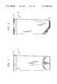
- FIG. 1is a rear elevation view of an exemplary enclosure according to the present invention.
- FIG. 2is a side elevation view of the enclosure shown in FIG. 1 .
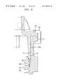
- FIG. 3is a cross sectional view of the enclosure of FIG. 1, with a first exemplary end cap partially inserted therein.
- FIG. 4is an enlarged detail of a portion of the enclosure shown in FIG. 3 .
- FIG. 5is a cross sectional view of the enclosure of FIG. 1, with a second exemplary end cap completely inserted therein.
- FIG. 6is an enlarged detail of a portion of the enclosure shown in FIG. 5 .
- the present inventionis a self-sealing telecommunications enclosure assembly 100 .
- FIGS. 1 and 2show the enclosure 110 , into which fiber and equipment (not shown), are installed.
- the interior of the enclosure 100may contain a card cage (not shown) having slots for accommodating a plurality of printed circuit boards having electrical circuits and/or electrical/optical transducers (not shown).
- the electrical circuitsmay provide a variety of functions, such as processing optical and electrical voice, data, and/or video signals, generating alarms and various signaling information, etc.
- the contents of the enclosuremay include a tray having a plurality of attachment sections into which optical fiber splices, connectors or standard end fiber terminations can be retained. Optical fiber which is not being coupled within the enclosure 110 can also be stored within the enclosure.
- FIG. 3is a cross sectional view of the enclosure assembly 100 , with the end cap 120 partially inserted in the enclosure 110 .
- FIG. 4is an enlarged view of the rim portion of the enclosure assembly 100 .
- the fiber optic enclosure assembly 100includes a fiber optic enclosure 110 having an inner rim 114 .
- the top of rim 114has a diameter that is larger than the diameter of the main part 111 of the enclosure 110 .
- a neck section 117transitions from the enlarged diameter of the rim section 114 to the reduced diameter of the main section 111 .
- the slope of the enclosure housing 110changes at two points 116 and 118 , which define the neck section 117 .
- the enclosure 110has an opening 113 through which pressurized air can be introduced to the enclosure.
- a valve(not shown) can be mounted in the hole 113 , to allow either introduction of air or the measurement of air pressure in the enclosure assembly 100 .
- the rim 114 and the main section 111are substantially vertical in cross section.
- the neck section 117is tilted at an angle between about 10 degrees and about 20 degrees from the vertical.
- there is a change in slope at location 116i.e., at the top of the neck section 117 ).
- An end cap 120is shaped to fit the enclosure 110 .
- the end cap 120has a plurality of cable ports 126 , through which cables (which may contain optical fibers) enter the enclosure assembly 100 .
- the cable ports 126may have a variety of sizes to accommodate differently sized cables.
- each of the cable ports 126Prior to installation, each of the cable ports 126 has a flat disk 126 a integrally attached to the end of the cable port.
- the flat disks 126 aare left on unused cable ports 126 until they are used, so that the enclosure assembly 100 can be sealed and pressurized.
- the top of the cable port, including the flat disk 126 ais cut off with a blade, which may be a saw blade.
- a sealis placed around the cable port, typically using a sleeve of heat shrink tubing.
- the end cap 120has a thin, pliable membrane 124 depending therefrom.
- the membrane 124extends into the inner rim 114 of the enclosure 110 when the end cap 120 is in place on the enclosure.
- the membrane 124is forced against the rim 114 when the enclosure 100 is pressurized, thereby forming a seal between the membrane and the rim.
- the exemplary membrane 124is approximately a cylindrical structure.
- the membrane 124may have a wedge shaped cross section, and preferably has a thickness that tapers off to a very thin pliable layer at the bottom of the membrane.
- a flexible material, such as polypropylene,is preferred for the membrane material.
- the membrane 124 and end cap 120may be formed from a single piece of material.
- the wedge shaped profileis advantageous. As the thickness of the membrane 124 tapers off to approximately zero thickness, the area moment of inertia of the membrane also tapers off. As a result, the bottom end of the membrane 124 is especially pliable, and can be more easily pressed into place against the neck 117 of the inner rim 114 by air pressure, as described in detail below.
- the membrane 124when the membrane 124 reaches the top 116 of the neck portion 117 , the membrane 124 deforms inwards towards the longitudinal axis of the enclosure 110 .
- a gapis formed between the outer circumference of membrane 124 and the neck section 117 of the enclosure 110 , best shown and described below with reference to FIG. 6 .
- the membrane 124deforms outward to bridge the gap when the enclosure is pressurized.
- FIGS. 5 and 6show a variation of the exemplary embodiment.
- FIG. 5shows an enclosure assembly 200 , including the same enclosure 110 as described above with reference to FIG. 3 .
- a slightly different end cap 220is used.
- Features of the end cap 220 that correspond to features of end cap 120 (FIG. 3)are indicated by reference numerals having the same last two digits.
- the membrane 224 of end cap 220has an elbow 225 in the wedge-shaped cross section, best seen in FIG. 6 . Below the elbow 225 , the thickness of the bottom portion 224 b of the membrane decreases more quickly than in the top section 224 a of the membrane. Thus, section 224 b has a desirable pliability.
- the gap 119(FIG. 6) between the membrane 224 and the neck 117 of the enclosure 110 is greater at the top 116 of the neck.
- a larger deformation by the bottom portion 224 b of the membrane 224occurs upon application of pressure.
- the end cap 220is inserted all the way into the rim 114 of the enclosure 110 .
- the enclosure 110 and end cap 220have respective mating parts 112 and 222 , which abut each other when the end cap is completely inserted.
- a clamp 230is applied to clamp the end cap 220 to the enclosure 110 , and to keep the end cap from moving.
- the clamp 230may be, for example, a V-clamp.
- U.S. Pat. No. 5,315,489 to McCall et al.is expressly incorporated by reference herein for its teachings on a clamp suitable for use on fiber enclosures. A clamp as described by McCall et al. may be used to clamp the enclosure assembly 200 .
- the gap 119is present between the membrane 224 and the neck portion 117 of the rim 114 before the enclosure assembly 200 is pressurized.
- the membrane 224moves against the rim 114 and the neck portion 117 to bridge the gap 119 when the enclosure assembly 200 is pressurized, thereby forming a seal between the membrane and the rim.
- This sealing action of the enclosure assembly 200occurs automatically upon pressurization of the enclosure, and is not sensitive to any slight misalignment of the end cap, or to the presence of any dirt or grease on the end cap 220 . So long as the end cap 220 is inserted completely, an adequate seal is formed. Thus, the installer can verify the integrity of the seal by visually inspecting the enclosure 200 to check whether the end cap is inserted in the enclosure.
- the pressureis released through the pressure valve (not shown), the clamp 230 is removed, and the enclosure is opened.
- the enclosures 100 and 200are closed and sealed by the same method described above.
- the exemplary embodimentis described in the context of a fiber optic enclosure, the exemplary enclosure is not limited to fiber, and may be used for other electronic equipment, where a water-tight seal is desired.
Landscapes
- Physics & Mathematics (AREA)
- General Physics & Mathematics (AREA)
- Optics & Photonics (AREA)
- Light Guides In General And Applications Therefor (AREA)
Abstract
Description
Claims (20)
Priority Applications (1)
| Application Number | Priority Date | Filing Date | Title |
|---|---|---|---|
| US09/363,572US6300562B1 (en) | 1999-07-29 | 1999-07-29 | Self-sealing telecommunications enclosure |
Applications Claiming Priority (1)
| Application Number | Priority Date | Filing Date | Title |
|---|---|---|---|
| US09/363,572US6300562B1 (en) | 1999-07-29 | 1999-07-29 | Self-sealing telecommunications enclosure |
Publications (1)
| Publication Number | Publication Date |
|---|---|
| US6300562B1true US6300562B1 (en) | 2001-10-09 |
Family
ID=23430766
Family Applications (1)
| Application Number | Title | Priority Date | Filing Date |
|---|---|---|---|
| US09/363,572Expired - Fee RelatedUS6300562B1 (en) | 1999-07-29 | 1999-07-29 | Self-sealing telecommunications enclosure |
Country Status (1)
| Country | Link |
|---|---|
| US (1) | US6300562B1 (en) |
Cited By (33)
| Publication number | Priority date | Publication date | Assignee | Title |
|---|---|---|---|---|
| US6711337B2 (en)* | 2001-05-21 | 2004-03-23 | Wave7 Optics, Inc. | Cable splice enclosure and components |
| US20050213921A1 (en)* | 2004-03-08 | 2005-09-29 | Mertesdorf Daniel R | Fiber access terminal |
| US7038910B1 (en) | 2002-01-07 | 2006-05-02 | Wave7 Optics, Inc. | System and method for removing heat from a subscriber optical interface |
| US20070237484A1 (en)* | 2006-04-05 | 2007-10-11 | Randy Reagan | Universal bracket for mounting a drop terminal |
| US7333708B2 (en) | 2004-01-27 | 2008-02-19 | Corning Cable Systems Llc | Multi-port optical connection terminal |
| US7340180B2 (en) | 2004-08-10 | 2008-03-04 | Wave7 Optics, Inc. | Countermeasures for idle pattern SRS interference in ethernet optical network systems |
| USRE40358E1 (en) | 1998-07-27 | 2008-06-03 | Adc Telecommunications, Inc. | Outside plant fiber distribution apparatus and method |
| US7389031B2 (en) | 2002-10-15 | 2008-06-17 | Wave7 Optics, Inc. | Reflection suppression for an optical fiber |
| WO2008098677A1 (en)* | 2007-02-14 | 2008-08-21 | Ccs Technology, Inc. | Cable joint |
| US7454141B2 (en) | 2003-03-14 | 2008-11-18 | Enablence Usa Fttx Networks Inc. | Method and system for providing a return path for signals generated by legacy terminals in an optical network |
| US7489849B2 (en) | 2004-11-03 | 2009-02-10 | Adc Telecommunications, Inc. | Fiber drop terminal |
| US20090046415A1 (en)* | 2004-05-28 | 2009-02-19 | American Power Conversion Corporation | Methods and apparatus for providing and distributing standby power |
| US20090060442A1 (en)* | 2003-07-17 | 2009-03-05 | Darren Dofher | Junction box housings for surface inlaid fibre optic network installations |
| US7512304B2 (en) | 2007-03-23 | 2009-03-31 | Adc Telecommunications, Inc. | Drop terminal with anchor block for retaining a stub cable |
| US7529485B2 (en) | 2001-07-05 | 2009-05-05 | Enablence Usa Fttx Networks, Inc. | Method and system for supporting multiple services with a subscriber optical interface located outside a subscriber's premises |
| US20090159332A1 (en)* | 2007-10-26 | 2009-06-25 | Matthew Holmberg | Cable seal assembly |
| US7558458B2 (en) | 2007-03-08 | 2009-07-07 | Adc Telecommunications, Inc. | Universal bracket for mounting a drop terminal |
| US7583897B2 (en) | 2002-01-08 | 2009-09-01 | Enablence Usa Fttx Networks Inc. | Optical network system and method for supporting upstream signals propagated according to a cable modem protocol |
| US7593639B2 (en) | 2001-08-03 | 2009-09-22 | Enablence Usa Fttx Networks Inc. | Method and system for providing a return path for signals generated by legacy terminals in an optical network |
| US7599622B2 (en) | 2004-08-19 | 2009-10-06 | Enablence Usa Fttx Networks Inc. | System and method for communicating optical signals between a data service provider and subscribers |
| US7606492B2 (en) | 2000-10-04 | 2009-10-20 | Enablence Usa Fttx Networks Inc. | System and method for communicating optical signals upstream and downstream between a data service provider and subscribers |
| US7616901B2 (en) | 2005-08-10 | 2009-11-10 | Enablence Usa Fttx Networks Inc. | Countermeasures for idle pattern SRS interference in ethernet optical network systems |
| US7623786B2 (en) | 2002-05-20 | 2009-11-24 | Enablence Usa Fttx Networks, Inc. | System and method for communicating optical signals to multiple subscribers having various bandwidth demands connected to the same optical waveguide |
| US7680388B2 (en) | 2004-11-03 | 2010-03-16 | Adc Telecommunications, Inc. | Methods for configuring and testing fiber drop terminals |
| US20100150517A1 (en)* | 2008-12-17 | 2010-06-17 | 3M Innovative Properties Company | Telecommunication enclosure with an interlocking seal |
| US7740409B2 (en) | 2007-09-19 | 2010-06-22 | Corning Cable Systems Llc | Multi-port optical connection terminal |
| US7844158B2 (en) | 2007-10-09 | 2010-11-30 | Adc Telecommunications, Inc. | Mini drop terminal |
| US7877014B2 (en) | 2001-07-05 | 2011-01-25 | Enablence Technologies Inc. | Method and system for providing a return path for signals generated by legacy video service terminals in an optical network |
| US7903923B2 (en) | 2007-10-09 | 2011-03-08 | Adc Telecommunications, Inc. | Drop terminal releasable engagement mechanism |
| US8755663B2 (en) | 2010-10-28 | 2014-06-17 | Corning Cable Systems Llc | Impact resistant fiber optic enclosures and related methods |
| US8873926B2 (en) | 2012-04-26 | 2014-10-28 | Corning Cable Systems Llc | Fiber optic enclosures employing clamping assemblies for strain relief of cables, and related assemblies and methods |
| US9069151B2 (en) | 2011-10-26 | 2015-06-30 | Corning Cable Systems Llc | Composite cable breakout assembly |
| US10320259B2 (en)* | 2013-03-25 | 2019-06-11 | Bison Gear & Engineering Corp. | Pull tight motor housing |
Citations (22)
| Publication number | Priority date | Publication date | Assignee | Title |
|---|---|---|---|---|
| US4913522A (en) | 1984-04-11 | 1990-04-03 | Nv Raychem Sa | Electrofit fibre optics butt splice |
| US4983008A (en) | 1986-08-22 | 1991-01-08 | Raychem Corporation | Strained distributed optical fiber communication system |
| US5059748A (en) | 1990-04-26 | 1991-10-22 | Raychem Corporation | Cable splice enclosure |
| US5069516A (en) | 1989-11-21 | 1991-12-03 | Raynet Corporation | Telecommunications closures |
| US5249253A (en) | 1984-04-11 | 1993-09-28 | Nv Raychem Sa | Electrofit fibre optics butt splice |
| US5286919A (en)* | 1991-06-28 | 1994-02-15 | Digital Equipment Corporation | Computer cable management system |
| US5308923A (en) | 1992-06-16 | 1994-05-03 | Raychem Corporation | Enclosure assembly for telecommunication cables |
| US5315489A (en) | 1992-12-10 | 1994-05-24 | Raynet Corporation | Pressure clamp for telecommunications closure |
| US5396575A (en) | 1992-12-18 | 1995-03-07 | Raynet Corporation | Sealed optical fiber closures |
| US5568362A (en)* | 1992-09-25 | 1996-10-22 | Atlas Copco Tools Ab | Cabinet for housing electronic equipment connectable to machines or power tools for performing operations |
| US5574251A (en)* | 1995-02-15 | 1996-11-12 | Hendry Mechanical Works | Electrical and electronic cabinet systems |
| US5602954A (en) | 1984-04-11 | 1997-02-11 | Raychem Sv | Electrofit fiber optics butt splice |
| US5710804A (en) | 1995-07-19 | 1998-01-20 | Pcs Solutions, Llc | Service protection enclosure for and method of constructing a remote wireless telecommunication site |
| US5726385A (en)* | 1995-12-29 | 1998-03-10 | Thomas & Betts Corporation | Thin wall electrical outlet box |
| US5837933A (en)* | 1997-08-07 | 1998-11-17 | Fligelman; Kenneth H. | Corrosion proof kill switch |
| US5864091A (en)* | 1996-07-03 | 1999-01-26 | Sumitomo Wiring Systems, Ltd. | Shock resistant electrical connection box |
| US6005188A (en)* | 1997-03-12 | 1999-12-21 | Krone Ag | Stationary housing with wall elements made of plastic |
| US6078718A (en)* | 1996-06-18 | 2000-06-20 | Siecor Corporation | Strain relief device for plurality of optical ribbon fibers |
| US6097872A (en)* | 1998-03-10 | 2000-08-01 | Fujitsu Limited | Optical telecommunication apparatus |
| US6147304A (en)* | 1999-03-05 | 2000-11-14 | Doherty; James W. | Electrical outlet box |
| US6157766A (en)* | 1997-06-20 | 2000-12-05 | Frances Telecom | High-density and high-capacity distribution frame for optical fibers |
| US6175079B1 (en)* | 1999-06-03 | 2001-01-16 | Tyco Electronics Corporation | Fiber optic cable management system |
- 1999
- 1999-07-29USUS09/363,572patent/US6300562B1/ennot_activeExpired - Fee Related
Patent Citations (24)
| Publication number | Priority date | Publication date | Assignee | Title |
|---|---|---|---|---|
| US5602954A (en) | 1984-04-11 | 1997-02-11 | Raychem Sv | Electrofit fiber optics butt splice |
| US5155794A (en) | 1984-04-11 | 1992-10-13 | Raychem Corporation | Electrofit fibre optics butt splice |
| US5249253A (en) | 1984-04-11 | 1993-09-28 | Nv Raychem Sa | Electrofit fibre optics butt splice |
| US4913522A (en) | 1984-04-11 | 1990-04-03 | Nv Raychem Sa | Electrofit fibre optics butt splice |
| US4983008A (en) | 1986-08-22 | 1991-01-08 | Raychem Corporation | Strained distributed optical fiber communication system |
| US5069516A (en) | 1989-11-21 | 1991-12-03 | Raynet Corporation | Telecommunications closures |
| US5059748A (en) | 1990-04-26 | 1991-10-22 | Raychem Corporation | Cable splice enclosure |
| US5286919A (en)* | 1991-06-28 | 1994-02-15 | Digital Equipment Corporation | Computer cable management system |
| US5308923A (en) | 1992-06-16 | 1994-05-03 | Raychem Corporation | Enclosure assembly for telecommunication cables |
| US5568362A (en)* | 1992-09-25 | 1996-10-22 | Atlas Copco Tools Ab | Cabinet for housing electronic equipment connectable to machines or power tools for performing operations |
| US5315489A (en) | 1992-12-10 | 1994-05-24 | Raynet Corporation | Pressure clamp for telecommunications closure |
| US5396575A (en) | 1992-12-18 | 1995-03-07 | Raynet Corporation | Sealed optical fiber closures |
| US5574251A (en)* | 1995-02-15 | 1996-11-12 | Hendry Mechanical Works | Electrical and electronic cabinet systems |
| US5911117A (en) | 1995-07-19 | 1999-06-08 | Pcs Solutions, Llc | Service protection enclosure for and method of constructing a remote wireless telecommunication site |
| US5710804A (en) | 1995-07-19 | 1998-01-20 | Pcs Solutions, Llc | Service protection enclosure for and method of constructing a remote wireless telecommunication site |
| US5726385A (en)* | 1995-12-29 | 1998-03-10 | Thomas & Betts Corporation | Thin wall electrical outlet box |
| US6078718A (en)* | 1996-06-18 | 2000-06-20 | Siecor Corporation | Strain relief device for plurality of optical ribbon fibers |
| US5864091A (en)* | 1996-07-03 | 1999-01-26 | Sumitomo Wiring Systems, Ltd. | Shock resistant electrical connection box |
| US6005188A (en)* | 1997-03-12 | 1999-12-21 | Krone Ag | Stationary housing with wall elements made of plastic |
| US6157766A (en)* | 1997-06-20 | 2000-12-05 | Frances Telecom | High-density and high-capacity distribution frame for optical fibers |
| US5837933A (en)* | 1997-08-07 | 1998-11-17 | Fligelman; Kenneth H. | Corrosion proof kill switch |
| US6097872A (en)* | 1998-03-10 | 2000-08-01 | Fujitsu Limited | Optical telecommunication apparatus |
| US6147304A (en)* | 1999-03-05 | 2000-11-14 | Doherty; James W. | Electrical outlet box |
| US6175079B1 (en)* | 1999-06-03 | 2001-01-16 | Tyco Electronics Corporation | Fiber optic cable management system |
Cited By (68)
| Publication number | Priority date | Publication date | Assignee | Title |
|---|---|---|---|---|
| USRE40358E1 (en) | 1998-07-27 | 2008-06-03 | Adc Telecommunications, Inc. | Outside plant fiber distribution apparatus and method |
| USRE42258E1 (en) | 1998-07-27 | 2011-03-29 | Adc Telecommunications, Inc. | Outside plant fiber distribution apparatus and method |
| USRE41777E1 (en) | 1998-07-27 | 2010-09-28 | Adc Telecommunications, Inc. | Outside plant fiber distribution apparatus and method |
| US7606492B2 (en) | 2000-10-04 | 2009-10-20 | Enablence Usa Fttx Networks Inc. | System and method for communicating optical signals upstream and downstream between a data service provider and subscribers |
| US20040161217A1 (en)* | 2001-05-21 | 2004-08-19 | Wave7 Optics, Inc. | Cable splice enclosure |
| US6950593B2 (en) | 2001-05-21 | 2005-09-27 | Wave7 Optics, Inc. | Cable splice enclosure |
| US6711337B2 (en)* | 2001-05-21 | 2004-03-23 | Wave7 Optics, Inc. | Cable splice enclosure and components |
| US7529485B2 (en) | 2001-07-05 | 2009-05-05 | Enablence Usa Fttx Networks, Inc. | Method and system for supporting multiple services with a subscriber optical interface located outside a subscriber's premises |
| US7877014B2 (en) | 2001-07-05 | 2011-01-25 | Enablence Technologies Inc. | Method and system for providing a return path for signals generated by legacy video service terminals in an optical network |
| US7593639B2 (en) | 2001-08-03 | 2009-09-22 | Enablence Usa Fttx Networks Inc. | Method and system for providing a return path for signals generated by legacy terminals in an optical network |
| US7355848B1 (en) | 2002-01-07 | 2008-04-08 | Wave7 Optics, Inc. | System and method for removing heat from a subscriber optical interface |
| US7038910B1 (en) | 2002-01-07 | 2006-05-02 | Wave7 Optics, Inc. | System and method for removing heat from a subscriber optical interface |
| US7583897B2 (en) | 2002-01-08 | 2009-09-01 | Enablence Usa Fttx Networks Inc. | Optical network system and method for supporting upstream signals propagated according to a cable modem protocol |
| US7623786B2 (en) | 2002-05-20 | 2009-11-24 | Enablence Usa Fttx Networks, Inc. | System and method for communicating optical signals to multiple subscribers having various bandwidth demands connected to the same optical waveguide |
| US7389031B2 (en) | 2002-10-15 | 2008-06-17 | Wave7 Optics, Inc. | Reflection suppression for an optical fiber |
| US8682162B2 (en) | 2003-03-14 | 2014-03-25 | Aurora Networks, Inc. | Method and system for providing a return path for signals generated by legacy terminals in an optical network |
| US7454141B2 (en) | 2003-03-14 | 2008-11-18 | Enablence Usa Fttx Networks Inc. | Method and system for providing a return path for signals generated by legacy terminals in an optical network |
| US7986880B2 (en) | 2003-03-14 | 2011-07-26 | Enablence Usa Fttx Networks Inc. | Method and system for providing a return path for signals generated by legacy terminals in an optical network |
| US20090060442A1 (en)* | 2003-07-17 | 2009-03-05 | Darren Dofher | Junction box housings for surface inlaid fibre optic network installations |
| US7609933B2 (en)* | 2003-07-17 | 2009-10-27 | Teraspan Networks Inc. | Junction box housings for surface inlaid fibre optic network installations |
| US7333708B2 (en) | 2004-01-27 | 2008-02-19 | Corning Cable Systems Llc | Multi-port optical connection terminal |
| US7653282B2 (en) | 2004-01-27 | 2010-01-26 | Corning Cable Systems Llc | Multi-port optical connection terminal |
| US7941027B2 (en) | 2004-03-08 | 2011-05-10 | Adc Telecommunications, Inc. | Fiber access terminal |
| US7480437B2 (en) | 2004-03-08 | 2009-01-20 | Adc Telecommunications, Inc. | Fiber access terminal |
| USRE43762E1 (en) | 2004-03-08 | 2012-10-23 | Adc Telecommunications, Inc. | Fiber access terminal |
| US7539387B2 (en) | 2004-03-08 | 2009-05-26 | Adc Telecommunications, Inc. | Fiber access terminal |
| US7539388B2 (en) | 2004-03-08 | 2009-05-26 | Adc Telecommunications, Inc. | Fiber access terminal |
| US7400815B2 (en) | 2004-03-08 | 2008-07-15 | Adc Telecommunications, Inc. | Fiber access terminal |
| US7397997B2 (en) | 2004-03-08 | 2008-07-08 | Adc Telecommunications, Inc. | Fiber access terminal |
| US8363999B2 (en) | 2004-03-08 | 2013-01-29 | Adc Telecommunications, Inc. | Fiber access terminal |
| US7292763B2 (en) | 2004-03-08 | 2007-11-06 | Adc Telecommunications, Inc. | Fiber access terminal |
| US20070140642A1 (en)* | 2004-03-08 | 2007-06-21 | Adc Telecommunications, Inc. | Fiber access terminal |
| US20050213921A1 (en)* | 2004-03-08 | 2005-09-29 | Mertesdorf Daniel R | Fiber access terminal |
| US7983797B2 (en)* | 2004-05-28 | 2011-07-19 | American Power Conversion Corporation | Methods and apparatus for providing and distributing standby power |
| US20090046415A1 (en)* | 2004-05-28 | 2009-02-19 | American Power Conversion Corporation | Methods and apparatus for providing and distributing standby power |
| US8670872B2 (en) | 2004-05-28 | 2014-03-11 | Schneider Electric It Corporation | Methods and apparatus for providing and distributing standby power |
| US7340180B2 (en) | 2004-08-10 | 2008-03-04 | Wave7 Optics, Inc. | Countermeasures for idle pattern SRS interference in ethernet optical network systems |
| US7953325B2 (en) | 2004-08-19 | 2011-05-31 | Enablence Usa Fttx Networks, Inc. | System and method for communicating optical signals between a data service provider and subscribers |
| US7599622B2 (en) | 2004-08-19 | 2009-10-06 | Enablence Usa Fttx Networks Inc. | System and method for communicating optical signals between a data service provider and subscribers |
| US10890729B2 (en) | 2004-11-03 | 2021-01-12 | Commscope Technologies Llc | Fiber drop terminal and bracket |
| US11567278B2 (en) | 2004-11-03 | 2023-01-31 | Commscope Technologies Llc | Fiber drop terminal |
| US7805044B2 (en) | 2004-11-03 | 2010-09-28 | Adc Telecommunications, Inc. | Fiber drop terminal |
| US10042136B2 (en) | 2004-11-03 | 2018-08-07 | Commscope Technologies Llc | Fiber drop terminal |
| US9851522B2 (en) | 2004-11-03 | 2017-12-26 | Commscope Technologies Llc | Fiber drop terminal |
| US12204157B2 (en) | 2004-11-03 | 2025-01-21 | Commscope Technologies Llc | Fiber drop terminal |
| US7680388B2 (en) | 2004-11-03 | 2010-03-16 | Adc Telecommunications, Inc. | Methods for configuring and testing fiber drop terminals |
| US7627222B2 (en) | 2004-11-03 | 2009-12-01 | Adc Telecommunications, Inc. | Fiber drop terminal |
| US7489849B2 (en) | 2004-11-03 | 2009-02-10 | Adc Telecommunications, Inc. | Fiber drop terminal |
| US7616901B2 (en) | 2005-08-10 | 2009-11-10 | Enablence Usa Fttx Networks Inc. | Countermeasures for idle pattern SRS interference in ethernet optical network systems |
| US20070237484A1 (en)* | 2006-04-05 | 2007-10-11 | Randy Reagan | Universal bracket for mounting a drop terminal |
| US7844160B2 (en) | 2006-04-05 | 2010-11-30 | Adc Telecommunications, Inc. | Universal bracket for mounting a drop terminal |
| US7477824B2 (en) | 2006-04-05 | 2009-01-13 | Adc Telecommunications, Inc. | Universal bracket for mounting a drop terminal |
| US20110123166A1 (en)* | 2006-04-05 | 2011-05-26 | Adc Telecommunications, Inc. | Universal bracket for mounting a drop terminal |
| US8218935B2 (en) | 2006-04-05 | 2012-07-10 | Adc Telecommunications, Inc. | Universal bracket for mounting a drop terminal |
| WO2008098677A1 (en)* | 2007-02-14 | 2008-08-21 | Ccs Technology, Inc. | Cable joint |
| US7558458B2 (en) | 2007-03-08 | 2009-07-07 | Adc Telecommunications, Inc. | Universal bracket for mounting a drop terminal |
| US7512304B2 (en) | 2007-03-23 | 2009-03-31 | Adc Telecommunications, Inc. | Drop terminal with anchor block for retaining a stub cable |
| US7740409B2 (en) | 2007-09-19 | 2010-06-22 | Corning Cable Systems Llc | Multi-port optical connection terminal |
| US7844158B2 (en) | 2007-10-09 | 2010-11-30 | Adc Telecommunications, Inc. | Mini drop terminal |
| US8213761B2 (en) | 2007-10-09 | 2012-07-03 | Adc Telecommunications | Mini drop terminal |
| US7903923B2 (en) | 2007-10-09 | 2011-03-08 | Adc Telecommunications, Inc. | Drop terminal releasable engagement mechanism |
| US20090159332A1 (en)* | 2007-10-26 | 2009-06-25 | Matthew Holmberg | Cable seal assembly |
| US8073302B2 (en)* | 2008-12-17 | 2011-12-06 | 3M Innovative Properties Company | Telecommunication enclosure with an interlocking seal |
| US20100150517A1 (en)* | 2008-12-17 | 2010-06-17 | 3M Innovative Properties Company | Telecommunication enclosure with an interlocking seal |
| US8755663B2 (en) | 2010-10-28 | 2014-06-17 | Corning Cable Systems Llc | Impact resistant fiber optic enclosures and related methods |
| US9069151B2 (en) | 2011-10-26 | 2015-06-30 | Corning Cable Systems Llc | Composite cable breakout assembly |
| US8873926B2 (en) | 2012-04-26 | 2014-10-28 | Corning Cable Systems Llc | Fiber optic enclosures employing clamping assemblies for strain relief of cables, and related assemblies and methods |
| US10320259B2 (en)* | 2013-03-25 | 2019-06-11 | Bison Gear & Engineering Corp. | Pull tight motor housing |
Similar Documents
| Publication | Publication Date | Title |
|---|---|---|
| US6300562B1 (en) | Self-sealing telecommunications enclosure | |
| CA2121009C (en) | Weather sealed male splice adaptor | |
| US5825963A (en) | Sub-surface fiber optic splice housing and method of splicing fiber optic cable | |
| EP3336992B1 (en) | Port entry device | |
| US7603020B1 (en) | Cable clamp with integrated trace and bond capability | |
| US6881901B2 (en) | Connection cover | |
| US5059748A (en) | Cable splice enclosure | |
| US4267401A (en) | Seal plug | |
| EP0430533B1 (en) | Water blocked cable portion and methods of making same | |
| US7526175B2 (en) | Feedthrough of submarine repeater and submarine repeater | |
| US5792991A (en) | Environmental seal | |
| US5598499A (en) | Seal for cable splice closure | |
| US5610370A (en) | Closure for cables | |
| TW202308238A (en) | Network access point (nap) enclosure | |
| KR102739069B1 (en) | System and method for carrying out leakage tests | |
| AU657812B2 (en) | A cable sleeve composed of a longitudinally-divided housing | |
| US6443457B1 (en) | Cable sealing device for various cable gauges | |
| US5842891A (en) | External ground isolation connector for cable splice closures | |
| US6463203B1 (en) | High pressure sealed telecommunications equipment enclosure | |
| CN101189776B (en) | Junction Box | |
| US8754331B2 (en) | Strain relief device | |
| US20210321522A1 (en) | Housing with a ventilation system for a control device | |
| US6263145B1 (en) | Densely packed cable port layout | |
| US20040140343A1 (en) | Vent hole sealing of hermetic packages | |
| WO2013069833A1 (en) | Packing assembly and cable connector using same |
Legal Events
| Date | Code | Title | Description |
|---|---|---|---|
| AS | Assignment | Owner name:LUCENT TECHNOLOGIES INC., NEW JERSEY Free format text:ASSIGNMENT OF ASSIGNORS INTEREST;ASSIGNOR:DAOUD, BASSEL H.;REEL/FRAME:010139/0786 Effective date:19990728 | |
| AS | Assignment | Owner name:AVAYA TECHNOLOGY CORP., NEW JERSEY Free format text:ASSIGNMENT OF ASSIGNORS INTEREST;ASSIGNOR:LUCENT TECHNOLOGIES, INC.;REEL/FRAME:011974/0433 Effective date:20000929 | |
| AS | Assignment | Owner name:BANK OF NEW YORK, THE, NEW YORK Free format text:SECURITY AGREEMENT;ASSIGNOR:AVAYA TECHNOLOGY CORP.;REEL/FRAME:012775/0144 Effective date:20020405 | |
| REMI | Maintenance fee reminder mailed | ||
| LAPS | Lapse for failure to pay maintenance fees | ||
| STCH | Information on status: patent discontinuation | Free format text:PATENT EXPIRED DUE TO NONPAYMENT OF MAINTENANCE FEES UNDER 37 CFR 1.362 | |
| FP | Lapsed due to failure to pay maintenance fee | Effective date:20051009 | |
| AS | Assignment | Owner name:AVAYA INC. (FORMERLY KNOWN AS AVAYA TECHNOLOGY COR Free format text:BANKRUPTCY COURT ORDER RELEASING ALL LIENS INCLUDING THE SECURITY INTEREST RECORDED AT REEL/FRAME 012775/0144;ASSIGNOR:THE BANK OF NEW YORK;REEL/FRAME:044893/0179 Effective date:20171128 |