US6299615B1 - System for fusing joints - Google Patents
System for fusing jointsDownload PDFInfo
- Publication number
- US6299615B1 US6299615B1US09/375,306US37530699AUS6299615B1US 6299615 B1US6299615 B1US 6299615B1US 37530699 AUS37530699 AUS 37530699AUS 6299615 B1US6299615 B1US 6299615B1
- Authority
- US
- United States
- Prior art keywords
- screw
- thread
- bone
- threads
- pitch
- Prior art date
- Legal status (The legal status is an assumption and is not a legal conclusion. Google has not performed a legal analysis and makes no representation as to the accuracy of the status listed.)
- Expired - Fee Related
Links
- 210000000988bone and boneAnatomy0.000claimsabstractdescription141
- 238000000034methodMethods0.000claimsabstractdescription23
- 210000003423ankleAnatomy0.000claimsdescription4
- 239000012634fragmentSubstances0.000description139
- 208000010392Bone FracturesDiseases0.000description14
- 230000007423decreaseEffects0.000description10
- 230000000694effectsEffects0.000description8
- 230000008859changeEffects0.000description7
- 238000009434installationMethods0.000description7
- 210000001503jointAnatomy0.000description7
- 208000037873arthrodesisDiseases0.000description6
- 230000006835compressionEffects0.000description6
- 238000007906compressionMethods0.000description6
- 230000004927fusionEffects0.000description5
- 210000001699lower legAnatomy0.000description5
- 230000012447hatchingEffects0.000description4
- 238000010276constructionMethods0.000description3
- 230000035876healingEffects0.000description3
- 238000001356surgical procedureMethods0.000description3
- 230000008901benefitEffects0.000description2
- 230000003247decreasing effectEffects0.000description2
- 210000002683footAnatomy0.000description2
- 230000003100immobilizing effectEffects0.000description2
- 230000003993interactionEffects0.000description2
- 230000008569processEffects0.000description2
- 210000002303tibiaAnatomy0.000description2
- 239000002023woodSubstances0.000description2
- 230000009286beneficial effectEffects0.000description1
- 230000015572biosynthetic processEffects0.000description1
- 238000000605extractionMethods0.000description1
- 210000001145finger jointAnatomy0.000description1
- 238000003780insertionMethods0.000description1
- 230000037431insertionEffects0.000description1
- 238000011900installation processMethods0.000description1
- 238000004519manufacturing processMethods0.000description1
- 239000000463materialSubstances0.000description1
- 230000013011matingEffects0.000description1
- 230000000399orthopedic effectEffects0.000description1
- 230000001737promoting effectEffects0.000description1
- 230000008439repair processEffects0.000description1
- 208000024891symptomDiseases0.000description1
- 210000004233talusAnatomy0.000description1
- 230000007704transitionEffects0.000description1
Images


Classifications
- A—HUMAN NECESSITIES
- A61—MEDICAL OR VETERINARY SCIENCE; HYGIENE
- A61B—DIAGNOSIS; SURGERY; IDENTIFICATION
- A61B17/00—Surgical instruments, devices or methods
- A61B17/56—Surgical instruments or methods for treatment of bones or joints; Devices specially adapted therefor
- A61B17/58—Surgical instruments or methods for treatment of bones or joints; Devices specially adapted therefor for osteosynthesis, e.g. bone plates, screws or setting implements
- A61B17/68—Internal fixation devices, including fasteners and spinal fixators, even if a part thereof projects from the skin
- A61B17/84—Fasteners therefor or fasteners being internal fixation devices
- A61B17/86—Pins or screws or threaded wires; nuts therefor
- A61B17/8625—Shanks, i.e. parts contacting bone tissue
- A61B17/863—Shanks, i.e. parts contacting bone tissue with thread interrupted or changing its form along shank, other than constant taper
- A—HUMAN NECESSITIES
- A61—MEDICAL OR VETERINARY SCIENCE; HYGIENE
- A61B—DIAGNOSIS; SURGERY; IDENTIFICATION
- A61B17/00—Surgical instruments, devices or methods
- A61B17/16—Instruments for performing osteoclasis; Drills or chisels for bones; Trepans
- A61B17/1662—Instruments for performing osteoclasis; Drills or chisels for bones; Trepans for particular parts of the body
- A61B17/1686—Instruments for performing osteoclasis; Drills or chisels for bones; Trepans for particular parts of the body for the hand or wrist
- A—HUMAN NECESSITIES
- A61—MEDICAL OR VETERINARY SCIENCE; HYGIENE
- A61B—DIAGNOSIS; SURGERY; IDENTIFICATION
- A61B17/00—Surgical instruments, devices or methods
- A61B17/56—Surgical instruments or methods for treatment of bones or joints; Devices specially adapted therefor
- A61B17/58—Surgical instruments or methods for treatment of bones or joints; Devices specially adapted therefor for osteosynthesis, e.g. bone plates, screws or setting implements
- A61B17/88—Osteosynthesis instruments; Methods or means for implanting or extracting internal or external fixation devices
- A61B17/8863—Apparatus for shaping or cutting osteosynthesis equipment by medical personnel
- A—HUMAN NECESSITIES
- A61—MEDICAL OR VETERINARY SCIENCE; HYGIENE
- A61B—DIAGNOSIS; SURGERY; IDENTIFICATION
- A61B17/00—Surgical instruments, devices or methods
- A61B17/56—Surgical instruments or methods for treatment of bones or joints; Devices specially adapted therefor
- A61B17/58—Surgical instruments or methods for treatment of bones or joints; Devices specially adapted therefor for osteosynthesis, e.g. bone plates, screws or setting implements
- A61B17/68—Internal fixation devices, including fasteners and spinal fixators, even if a part thereof projects from the skin
- A61B17/84—Fasteners therefor or fasteners being internal fixation devices
- A61B17/86—Pins or screws or threaded wires; nuts therefor
- A61B17/8625—Shanks, i.e. parts contacting bone tissue
- A61B17/8635—Tips of screws
- A—HUMAN NECESSITIES
- A61—MEDICAL OR VETERINARY SCIENCE; HYGIENE
- A61B—DIAGNOSIS; SURGERY; IDENTIFICATION
- A61B17/00—Surgical instruments, devices or methods
- A61B17/56—Surgical instruments or methods for treatment of bones or joints; Devices specially adapted therefor
- A61B17/58—Surgical instruments or methods for treatment of bones or joints; Devices specially adapted therefor for osteosynthesis, e.g. bone plates, screws or setting implements
- A61B17/68—Internal fixation devices, including fasteners and spinal fixators, even if a part thereof projects from the skin
- A61B17/84—Fasteners therefor or fasteners being internal fixation devices
- A61B17/86—Pins or screws or threaded wires; nuts therefor
- A61B17/8645—Headless screws, e.g. ligament interference screws
- A—HUMAN NECESSITIES
- A61—MEDICAL OR VETERINARY SCIENCE; HYGIENE
- A61B—DIAGNOSIS; SURGERY; IDENTIFICATION
- A61B17/00—Surgical instruments, devices or methods
- A61B17/064—Surgical staples, i.e. penetrating the tissue
- A61B2017/0646—Surgical staples, i.e. penetrating the tissue for insertion into cartillege, e.g. meniscus
- A—HUMAN NECESSITIES
- A61—MEDICAL OR VETERINARY SCIENCE; HYGIENE
- A61B—DIAGNOSIS; SURGERY; IDENTIFICATION
- A61B17/00—Surgical instruments, devices or methods
- A61B17/064—Surgical staples, i.e. penetrating the tissue
- A61B2017/0647—Surgical staples, i.e. penetrating the tissue having one single leg, e.g. tacks
- A61B2017/0648—Surgical staples, i.e. penetrating the tissue having one single leg, e.g. tacks threaded, e.g. tacks with a screw thread
Definitions
- the present inventionrelates generally to a bone screw for drawing together bone fragments separated by a fracture and more particularly to such a screw which draws the bone fragments together as a result of different-pitched threads on the screw.
- a number of prior art bone screwshave been constructed in a fashion resembling wood screws.
- some prior art bone screwsinclude a threaded distal portion and a head with a relatively long unthreaded shank disposed between the head and the distal portion.
- a drillis used to create a bore through the fracture and the screw is threaded into the remote bone fragment with the head of the screw compressing the near fragment tightly against the remote bone fragment.
- bone screwsare threaded along the length thereof thus requiting a first drill bit to create a bore in both bone fragments extending across the fracture and a second bit to drill a larger bore in the near bone fragment so that the screw threads do not engage the near bone fragment Thereafter, the screw is tightened in the same manner as described above in connection with the screw having an unthreaded shank, thereby compressing the fragments together.
- FIGS. 8A-10DThe operation of two prior art headed lag screws is illustrated in FIGS. 8A-10D.
- the operation of a lag screw A 1 with a head B 1 , and a shank C 1is shown in FIGS. 8A-D.
- Shank C 1 of screw A 1includes threads D 1 at the distal end and an unthreaded region E 1 proximal to head B 1 .
- the pitch of threads D 1is constant.
- FIG. 8Ashows screw A 1 partially engaged in a bore F 1 in a near bone fragment G 1 .
- the diameter of bore F 1is less than the diameter of threads D 1 and therefore the threads engage the walls of the bore as the screw is twisted in.
- FIG. 8Bshows screw A 1 as it starts threading into a bore H 1 in a remote bone fragment I 1 .
- threads D 1are engaged in both bores and moving forward at the same speed in both fragments so no compression between the fragments is achieved.
- Head B 1has reached the top of fragment G 1 in FIG. 8C, as indicated schematically by the radiating “force” lines. Since threads D 1 are no longer engaged in fragment G 1 , screw A 1 rotates freely in the fragment without being drawn forward therein Subsequent rotation of screw A 1 draws fragment I 1 further up the screw. Because head B 1 prevents fragment G 1 from moving further up screw A 1 , fragment I 1 is drawn up against fragment G 1 and compression between the fragments is achieved as shown in FIG. 8D, with the head pulling down on the near fragment and the threads pulling up on the remote fragment.
- FIGS. 9A-dThe importance of the unthreaded region of screw A 1 is illustrated in FIGS. 9A-d.
- a lag screw A 2 including a head B 2 and a shank C 2is shown partially engaged in a bore F 2 in a near fragment G 2 in FIG. 9 A.
- Shank C 2includes threads D 2 running the entire length with no unthreaded region such as E 1 on screw A 1 .
- Rotating screw A 2causes it to be drawn through fragment G 2 and pass into a bore H 2 in a remote fragment I 2 , as shown in FIG. 9 B. Further rotation of screw A 2 brings head B 2 down against the upper surface of fragment G 2 . See FIG. 9 C.
- FIGS. 10A-DThe proper bore configuration for using screw A 2 is illustrated in FIGS. 10A-D.
- bore F 2 in fragment G 2is enlarged to allow threads D 2 of screw A 2 to pass freely through the bore. Screw A 2 therefore slips into bore F 2 until it reaches fragment I 2 . At that point threads D 2 engage the walls of bore H 2 and draw screw A 2 down into fragment I 2 . See FIGS. 10B-C.
- head B 2reaches the upper surface of fragment G 2 , further rotation causes fragment I 2 to be drawn up into contact with fragment G 2 as shown in FIGS. 10C-D. No binding occurs between head B 2 and reads D 2 in the near fragment because of the large bore in fragment G 2 , and the screw functions as intended to draw the two fragments together.
- FIGS. 11A-12Dillustrate the effect of substituting headless screws in the place of lag screws A 1 and A 2 .
- FIG. 11Ashows a headless screw A 3 partially installed in a bore F 3 in a near fragment G 3 .
- Screw A 3includes threads D 3 extending along its entire length The pitch of threads D 3 is constant.
- FIG. 11Bshows screw A 3 extending through fragment G 3 and just entering a bore H 3 in a remote fragment I 3 .
- FIG. 11Cshows screw A 3 advanced further into fragment I 3 .
- screw A 3moves forward in fragments G 3 and I 3 by the same amount with each rotation.
- screw A 3will pass through both fragments without altering their relative spacing or compressing them together.
- a headless screwsuch as screw A 3 will not work to draw the fragments together in the same way as lag screws A 1 and A 2 .
- Screw A 4includes threads D 4 of constant pitch extending along its entire length and differs from screw A 3 in that it tapers from a smaller outside diameter at the leading end to a larger outside diameter at the trailing end. Screw A 4 is shown because it incorporates tapering which is one of the features of the present invention, however, it is unknown whether such a screw is found in the prior art Screw A 4 is shown partially installed in a bore F 4 in a near fragment G 4 in FIG. 12 A. As screw A 4 is rotated, it moves through fragment G 4 and into a bore H 4 in a remote fragment I 4 , as shown in FIG. 12 B.
- FIG. 13Ashows a headless screw As with threads D 5 formed along its entire length.
- Such a screwis shown in U.S. Pat. No. 146,023 to Russell.
- the pitch of threads D 5varies from a maximum at the leading end to a minimum at the trailing end It is expected that such a screw moves forward upon rotation in a fragment according to the approximate average pitch of the threads engaged in the fragment. Screw A 5 is shown in FIG.
- screw A 5in contrast to constant pitch screws such as screws A 1 and A 2 , can be used to separate fragments G 5 and I 5 by simply reversing the rotation.
- FIG. 14Ashows a headless screw A 6 , such as disclosed in U.S. Pat. No. 4,175,555 to Herbert, that offers one solution to the problem of reaming of threads.
- headless screw A 6such as disclosed in U.S. Pat. No. 4,175,555 to Herbert, that offers one solution to the problem of reaming of threads.
- bone screws having headssuffer from several disadvantages including concentrated loads beneath the screw head and the protrusion of the screw head itself after the screw is installed.
- Several other shortcomings of the standard type of bone screware detailed in the Herbert patent.
- Screw A 6as per Herbert, includes a shank C 6 with leading threads J 6 at the leading end, trail threads K 6 at the trailing end and an unthreaded region E 6 separating the leading and trailing threads. Threads J 6 and K 6 each have fixed pitch, but leading threads J 6 have a larger pitch and smaller outside diameter than trailing threads K 6 .
- FIG. 14Ashows leading threads J 6 of screw A 6 installed in a bore F 6 of a near fragment G 6 . It should be noted that threads J 6 do not engage the walls of bore F 6 , the bore having been bored large enough to allow leading threads J 6 to pass freely. As the screw moves forward, the leading threads engage a bore H 6 in a remote fragment I 6 . See FIG. 14 B. The diameter of bore H 6 is adapted so that leading threads J 6 engage the walls. Meanwhile, at the trailing end of the screw, trailing threads K 6 start to engage the walls of bore F 6 , which has been bored to an appropriate diameter therefor.
- Screw A 6operates on the same general principle as screw A 5 , except that the average pitch of the threads in the remote and near fragments is simply the pitch of the leading and ting threads, respectively. For instance, if the pitch of the leading threads is 0.2 inches and the pitch of the trailing threads is 0.1 inches, each rotation of screw A 6 will move it 0.2 inches further into fragment H 6 , but only 0.1 inches further into fragment I 6 , thus moving the fragments 0.1 inches closer together.
- the Herbert screwovercomes at least one of the drawbacks of the Russell screw, the reaming of female threads by subsequent threads on the screw, but at the same time suffers from a number of other disadvantages.
- the leading threadshave a smaller diameter than the trailing threads. This is necessary to permit the leading threads to pass through the relatively large bore in the near bone fragment and engage the smaller bore in the remote bone fragment. The larger trailing threads then engage the larger bore in the near bone fragment As a result of this arrangement, any stripping of the threads cut into the bones during installation of the screw occurs in the remote bone.
- the Herbert screwmust be correctly positioned, i.e., it is imperative that the fracture intersect the unthreaded central portion of the Herbert bone screw when the same is installed.
- the Herbert screwis not suitable for treating fractures that are very near the surface of the bone where the hole is to be drilled.
- the Herbert screwis not threaded entirely along the length thereof the purchase obtained by the screw in the bone is not as good as with a screw threaded along the entire length.
- two bores of different sizesmust be drilled to install the Herbert screw rather than a single bore.
- axial boresare drilled in the particular surfaces of the distal and proximal phalanges.
- the bore in the distal boneis sufficiently large to receive without threading a screw which is inserted therein via an incision in the tip of the finger.
- the screwthreadably engages the bore in the proximal bone and when the screw head is tightened against the distal end of the distal bone, the two bones are compressed together. After several weeks, the bones fuse together.
- a second procedure to remove the screwmust be performed because the head of the screw will cause discomfort in the finger pad if the screw is not removed.
- a bone screw for drawing together bone fragments separated by a fractureincludes a root portion having a leading end and a trailing end. The leading end has a smaller diameter than the trailing end.
- a screw threadis formed on the root portion between the leading and trailing ends and has a pitch which varies along the length thereof, having a larger pitch near the leading end and a smaller pitch near the filing end. The thread is adapted to thread in the cancellous material of the respective bone fragments to be joined by the screw.
- Meansare provided on the trailing end of the root portion to accommodate a tool for driving the screw.
- the present inventionalso contemplates a method for drawing together bone fragments separated by a fracture.
- FIG. 1is an enlarged side elevation view of a bone screw constructed in accordance with the present invention
- FIG. 1Ais a view of the screw of FIG. 1 shown partially in cross section;
- FIG. 2is an end view of the bone screw of FIG. 1;
- FIG. 3is a drawing illustrating the outside diameter of the screw
- FIG. 4is a drawing illustrating the diameter of the root portion of the screw
- FIG. 5is a cross-sectional view of a bone screw constructed in accordance with the present invention installed in a bone to draw a fracture together;
- FIG. 6is a side elevation view of a bone screw constructed in accordance with the present invention which may be used for interphalangeal joint arthrodesis;
- FIG. 7is a view of the bone screw of FIG. 5 installed in a distal interphalangeal joint with the bones forming the joint as shown in cross-section;
- FIGS. 8A-14Dshow the operation of various screws to compress two bone fragments together
- FIGS. 15A-Dshow the operation of a screw constructed according to an alternative embodiment of the present invention to compress two bone fragments together;
- FIGS. 16A-Bare detailed views of the screw shown in FIGS. 15C and 15D, respectively;
- FIG. 17Ais a side elevation view of a bone screw constructed according to an alternative embodiment of the present invention.
- FIG. 17Bis a representation of the side profile of a root portion of the screw of FIG. 17A;
- FIG. 17Cis a representation of the outside diameter of the screw of FIG. 7A;
- FIG. 18Ais a side elevation view of a bone screw constructed according to a fourth embodiment of the present invention.
- FIG. 18Bis a representation of the side profile of a root portion of the screw of FIG. 18A;
- FIG. 18Cis a representation of the outside diameter of the screw of FIG. 8A;
- FIG. 19is an enlarged side elevation view of a bone screw constructed in accordance with an alternative embodiment of the present invention.
- FIG. 19Ais a view of the screw of FIG. 19 shown partially in cross section
- FIG. 20is an end view of the bone screw of FIG. 19;
- FIG. 21 aillustrates the outside diameter and root profile of an alternative embodiment of the present invention.
- FIG. 21 bis an elevational view of the screw of FIG. 21 a.
- Bone screw 10is centered on a longitudinal axis 11 .
- the length of screw 10 as measured along axis 11is 0.394 inches in the present embodiment of the invention.
- the bone screwincludes a root portion 12 having a continuous screw thread 14 formed thereon.
- Root portion 12includes a leading end 16 and a trail end 18 . As can best be seen in FIG. 4, the diameter of leading end 16 is less than the diameter of trailing end 18 . Also in FIG. 4, it can be seen that root portion 12 tapers between trailing end 18 and leading end 16 . A 45° bevel 20 , in FIGS. 1 and 1A, is formed on trailing end 18 . In the present embodiment of the invention, tailing end 18 has a diameter of approximately 0.092 inches. A frusto-conical nose portion 22 is formed on leading end 16 of root portion 12 .
- Screw thread 14extends continuously between nose portion 22 and bevel 20 .
- a tailing thread 24has a crest height, i.e., the distance between axis 11 and a crest 26 of trailing thread 24 , which varies so as to form a substantially 45° angle, illustrated as angle 28 in FIG. 3, between the outside diameter of crest 24 and axis 11 .
- a similarly tapering leading thread 30also has a crest 32 which varies in height over a first partial time of screw thread 14 so as to form an angle of substantially 45° with axis 11 as illustrated in FIG. 3 .
- the crest of screw thread 14 between trailing and leading threads 24 , 30 respectively,varies in height along the length of thread 14 .
- the outside diameter defined by the crest of thread 14 between the leading and trailing threadsforms an angle 34 , in FIG. 3, of approximately 1.43° with respect to an axis 35 extending from the radially outermost portion of thread 14 parallel to axis 11 .
- the diameter of the radially outermost portion of thread 14is approximately 0.138 inches.
- the pitch of thread 14i.e., the distance from one point on the thread to the corresponding point on an adjacent thread measured parallel to axis 11 , decreases between the leading and trailing ends of the screw. It should be noted that the term pitch is also sometimes used to refer to the number of threads per unit length, i.e., 20 threads per inch This alternative definition is simply the inverse of the definition chosen for use in this application. The distinction is important to remember for proper understanding of the subsequent description because the screw of the present invention relies on varying pitch to achieve its function.
- the distance between the uppermost portion of crest 32 and a corresponding crest portion 36is 0.04964 inches.
- the distance between the uppermost portion of crest 26 and a corresponding crest portion 38is 0.04748 inches.
- the pitch change per revolutionis approximately 0.00036 inches.
- the pitch depthi.e., the distance between the crest and the radially outer surface of root portion 12 similarly varies along the length of the screw.
- the pitch depth where leading thread 30 joins the remainder of screw thread 14is approximately 0.0302 inches.
- the pitch depth where trailing thread 24 joins the remainder of thread 14is approximately 0.0240 inches.
- the decrease in pitch depth between the leading end and trailing end of the screwcan be seen by comparing FIG. 3 and FIG. 4 wherein root portion 12 tapers more sharply from the trailing to the leading end of the screw than does the change in crest height as shown in FIG. 3 .
- the outside diameter of root portion 12 between leading and talk ends, 16 , 18 , respectivelyforms an angle 40 , in FIG. 4, of approximately 2.5° with respect to an axis 42 extending from the radially outermost portion of trailing end 18 parallel to axis 11 .
- a hex socket 44is formed on the trading end of screw 10 to accommodate a driver as will be hereinafter further explained in connection with a description of the procedure in which the screw is used to draw opposing fragments of a fractured bone together.
- Screw 410includes a root portion 412 on which is formed a thread 414 .
- Thread 414extends from a leading end 416 to a trailing end 418 and includes a land 474 .
- the pitch of thread 414 at the leading endis 0.055 inches and the pitch at the tang end is 0.035 inches.
- the landvaries from 0.010 inches to 0.004 inches overt the same range.
- Thread 414includes a cutting flute 415 near the leading end to facilitate the cutting of female threads as the screw is installed.
- Both the outside diameter of thread 414 and root 412taper from a smaller value at the leading end to a larger value at the bailing end. See FIGS. 21-22.
- the root diametertapers from 0.062 inches to 0.122 inches, while the outside diameter tapers from 0.130 inches to 0.156 inches.
- the length of screw 410is 0.689 inches.
- Screw 410also includes an axial bore 425 which extends from the leading end to the trailing end. Bore 425 is adapted to receive a stiff guide wire, not shown, which facilitates installation of screw 410 .
- a hex socket 444is formed at the trailing end to allow the screw to be driven by an hex wrench See FIG. 20 .
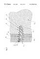
- FIG. 5illustrated therein is a fracture 46 which separates adjacent bone fragments 48 , 50 .
- Screw 10is illustrated installed in a bore 52 which extends through bone fragments 48 , 50 across fracture 46 .
- a surgeonIn installing screw 10 , a surgeon first drills bore 52 across bone fragments 48 , 50 as shown
- the bitmay be a conventional cylindrical bone bit or may comprise a bit having a slight taper from the leading to the trailing end thereof. Thereafter, the surgeon inserts a tool (not shown) having a hex driver extending therefrom which is connectable to hex socket 44 for screwing screw 10 into bore 52 .
- Bore 52is of a size to just receive leading end 16 of screw 10 .
- torqueis applied using the tool inserted into hex socket 44 thereby causing leading thread 30 to cut into the bone adjacent bore 52 .
- screw 10is hatched to show the path cut by leading thread 30 after screw 10 is installed in the position illustrated in FIG. 5 .
- the path of thread 30is depicted using hatching, like hatching 54 , 56 , 58 which indicates the position of the path cut by leading thread 30 relative to succeeding threads of the screw.
- Hatching 60depicts the actual position of the thread on screw 10 and root 12 . It is to be appreciated that hatching 54 , 60 are not used in FIG. 5 to depict different structure, which is unitary as illustrated in FIG. 1, but to depict relative positions of the path cut by leading thread 30 in the actual position of subsequent threads in the installed screw.
- each successive thread received in the path cut by thread 30exerts pressure against the right side (as viewed in FIG. 5) of the path cut by thread 30 thereby tending to compress the bone along the length of the screw.
- trailing thread 24compresses a substantial amount of bone when it is received in the path cut by thread 30 . This tends to draw bone fnents 48 , 50 tightly together across fracture 46 thereby promoting healing of te fracture.
- each succeeding portion of the threadis spaced further radially outwardly as a result of the taper and therefore the outer portion of each thread (that portion closely adjacent the crest) cuts into new bone which was not cut by the preceding thread
- Thisprovides a much better purchase than would a thread having a continuously varying pitch with constant diameter.
- each succeeding threadcuts additional bone within the generally cylindrical volume defined by the outside diameter of the threads. The outer portion of each thread (that portion closely a 4 jacent the crest) therefore cuts into bone uncut by the preceding thread.
- the tapered rootis also advantageous in that the radially outer surface of the root, i.e., that portion between adjacent threads, is tightly urged against uncut bone defining the wall of bore 52 . It is desirable to maximize the surface area of screw 10 urged against adjacent bone, rather than a space cut by a thread, to increase purchase of the screw.
- FIGS. 15A-Dillustrate the operation a screw 310 to draw together and join bone fragments 348 and 350 .
- FIG. 15Ashows screw 310 partially installed in a bore 349 in bone fragment 348 .
- Screw 310is shown just entering a bore 351 in bone fragment 350 in FIG. 15 B.
- Subsequent rotation of screw 310starts the process of drawing the bone fragments together as shown in FIGS. 15C-D.
- FIG. 16Ashows the interaction of a thread 314 in bores 349 and 351 when screw 310 is positioned therein as shown in FIG. 15 C.
- a leading end 316 of screw 310is engaged in bore 349 .
- Each revolution of the thread 314is labelled for reference in the subsequent discussion, from thread T 1 at the leading end to thread T 23 at the trailing end.
- thread 314will cut a mating female thread 353 .
- female thread 353will not precisely match thread 314 of screw 310 along its entire length.
- subsequent threadswill not track in the same path as the preceding threads, a pattern of leading gaps 355 and trailing gaps 357 will evolve between female thread 353 and screw thread 314 as the screw moves forward in the bores.
- the screwwill move forward in the bone fragment with rotation at a rate that is a function of the competing forces from all of the threads engaged in the bore.
- the ratewill correspond to an effective pitch of the threads in the bore and will be equal to the pitch of the screw at an effective pitch point 359 along the portion of the screw engaged in the fragment.
- the effective pitch pointwill move back along the screw and further into the bone fragment.
- the location of the effective pitch pointwill stabilize at a relatively constant location in the bone fragment, simply moving back along the screw at the rate the screw moves forward in the bore.
- the threads ahead of the effective pitch pointwhich will be referred to as the plling threads 371 , will have greater pitch than the effective pitch.
- the threads behind the effective pitch poit, or dragging threads 373will have a pitch that is smaller than the effective pitch.
- the pulling threads in fragment 348are T 1 -T 4 and the dragging threads are T 5 and T 6 .
- each rotation of the screwwill move it forward in fragment 348 by an amount corresponding to the present value of the effective pitch.
- the effective pitchwill be equal to the pitch of thread 314 between threads T 4 and T 5 .
- Thread T 1will always be cutting a new thread path in the fragment, so no gap will form around it.
- Thread T 2will attempt to follow the track of thread T 1 in fragment 348 , which would carry it forward by an amount equal to the pitch between thread T 1 and T 2 .
- thread T 2can only move forward by the same amount This causes thread T 2 to pull back against the surrounding bone and creates a leading gap in front that thread.
- thread T 3will attempt to move into the position of thread T 2 , but will be held back from moving as far forward as its pitch would indicate, thus creating a leading gap as thread T 3 is pulled back against the surrounding bone.
- thread T 6will attempt to move into the prior position of thread T 5 , but will be dragged forward somewhat, leaving a trailing gap.
- Bone fragment 350includes leading gaps 361 and trailing gaps 363 similar to those found in bone fiagment 348 . However, because more of the screw has moved through bone fragment 350 , the gaps have evolved to a greater extent The earlier position of screw 310 in fragment 350 is shown in dotted lines in FIG. 16A to illustrate the evolution of the threads as the screw moves forward.
- the effective pitch pointfalls at approximately thread T 8 .
- the effective pitch pointis at approximately thread T 16 , the screw having completed approximately 8 revolutions between the two positions.
- the current and prior screw positionsare aligned at effective pitch point 367 in fragment 350 based on the assumption that thread 314 will track through this point uniformly. The evolution of the position of threads behind and ahead of the effective pitch point can thus be seen by comparing the prior position with the current position.
- Leading gaps 361have a sloping upper surface 365 , which is a result of the gradual expansion of the outside diameter of thread 314 toward the trailing end of the screw.
- Upper surface 365represents a line from the prior position of the thread to the position as shown. As thread 314 at a given point in the bone fragment is held back, it simultaneously expands in diameter. This effect prevents thread 314 from completely reaming out the female thread in the bone fragment, as discussed above. Without the taper, sloping upper surface 365 would be flat and as soon as the width of the gap grew to equal the spacing between the threads, there would be no purchase left for subsequent threads along a portion of the bore.
- the other factor tending to cause the pitch point to be closer to the surface of the bonerelates to balancing the amount of bone displaced as the leading and trailing gaps are formed.
- the pulling threads 371which have pitch greater than the effective pitch, are held back from moving as far forward with each rotation as their pitch would indicate.
- dragging threads 373are drawn forward faster tand their pitch would dictate. This effect creates leading gaps 355 in front of pulling threads 371 as 20 they pull against the surrounding bone.
- trailing gaps 357form behind dragging threads 373 as they are dragged forward through the surrounding bone.
- FIG. 16Bshows how the pattern of gaps changes once the two bone fragments have been drawn together. After the bone fragments meet, the pattern of gaps starts to evolve toward that found in a single fragment In particular, gaps form or increase on the leading side of all of the pulling threads ahead of an effective combined pitch point 369 , and on the traling side of all the dragging reads behind the effective combined pitch point. Near the joint between the fragments, the gaps will generally transition from leading to trailing and vice versa, because the dragging threads in fragment 348 near the joint are converted to pulling threads after the joint closes. The pulling threads in ftagment 350 likewise become dragging hireads after the fragments meet.
- Rotation of screw 310 after the bone fragments have come togethertends to increase the pressure in the joint between them. Additional rotation can be used to set the depth of the screw as desired. Since the outside diameter of the thread tapers, as described above, the screw can be driven in until the trailing end is below the surface of the bone without danger of stripping the female thread formed by the preceding threads, even if the bone fragments first meet with the trailing end protruding substantially. This is because subsequent thiads expand and cut into some new bone even as they partially ream the female threads left by preceding threads on the screw. This is in contrast to the Herbert screw, where, as discussed above, additional tightening after the fragments have come together can strip out the threads in the distal fagment and reduce compression. Since it is important in the preferred application of the present invention to have the trailing end of the screw below the surface of the bone, this is an important feature and advantage over prior art screws.
- the tolerance in the screw of the present invention to further tightening after the fragments have come togetheris also important because it simplifies the installation process by eliminating the danger of over-tightening that must be guarded against when using the Herbert screw.
- Bone screw 62is sized and constructed for use in connection with intelphalangeal joint arthrodesis.
- Screw 62includes a tapered root 64 having a thread 65 formed thereon from a leading end 63 to a trailing end 67 , a substantially cylindrical leading extension 66 joined to the leading end and a substantially cylindrical tailing extension 68 joined to the tailing end.
- the diameter of leading extension 66is slightly larger than root 64 at leading end 63
- the diameter of railing extension 68is slihe* smaller than root 64 at trailing end 67 .
- the trailing extension 68includes a hex socket (not visible), like hex socket 44 in FIG. 1A, formed on an end surface 70 thereof
- Leading extension 66includes a tapered nose 72 formed on the forward end thereof
- screw 62is 1.259 inches in length with the threaded portion being 0.630 inches long and the diameter of leading extension 66 being 0.05 inches.
- the trailing extension diameteris 0.100 inches.
- the pitch of thread 65decreases between the leading and trailing ends.
- a land 74is formed in the crest of thread 65 and decreases in width between the leading and trailing ends of the screw.
- a distal phalanx 76comprises the outermost bone of one of the four fingers.
- a proximal phalanx 78is adjacent thereto with a distal interphalangeal (DIP) joint 80 being formed therebetween.
- DIPdistal interphalangeal
- the jointincludes a pair of articular surfaces 82 , 84 which have been flattened in accordance with a known technique for immobilizing DIP joint 80 .
- Bores 86 , 88are drilled into each of phalanxes 76 , 78 from articular surfaces 82 , 84 , respectively.
- the bonesare repositioned as shown in FIG. 7 and screw 62 is driven into the distal end of the bore in phalanx 76 until the screw is positioned as shown in FIG. 7 .
- Screw 62thus compresses across joint 80 even though it has a relatively small diameter, which is critical in DIP joint arhirodesis because of the small diameter of the bones involved. Screw 62 also has sufficient length, due to the leading and traling extensions 66 , 68 , to provide stability while the bones are fusing. Because the screw is entirely received within the bones, i.e., there is no protrusion from the screw, it can remain implanted and thus a second procedure to remove the bone is not necessary.
- Screw 110includes a root portion 112 on which is formed a continuous screw thread 114 and associated land 174 .
- Screw 110includes a leading end 116 and a tailing end 118 .
- Leading cutting flutes 115are fonned in thread 114 near leading end 116 to help the thread self tap into the bone.
- a series of tig cutting flutes 117are formed in thread 114 along the sides of the screw toward the trailing end. Trailing cutting flutes 117 facilitate istallation and removal of the screw by helping to cut a thread path in the bone.
- Screw 110may be formed with two sets of halig cutting flutes, one oriented to cut female threads upon insertion and another oriented to cut female threads upon removal of the screw, thus easing both installation and extraction.
- a hex socket 144is formed in the trailing end of screw 110 to receive a drive tool.
- Screw 110is forned with a variable pitch portion 119 and a constant pitch portion 121 .
- Variable pitch portion 119extends from leading end 116 back toward traling end 118 for about 70 percent of the length the of the screw.
- the length of the screwis 0.961 inches.
- screw 110does not include a bevel at the trailing end as formed on screw 10 and shown at 20 in FIG. 1A The bevel was elnninated in screw 110 to provide additional structal support around hex socket 144 which is used for drving the screw.
- Variable pitch portion 119 of screw 110is formed according to the previously described construction of screw 10 .
- the pitch of thread 114is largest at leading end 116 and decreases over variable pitch portion 119 back toward traig end 118 .
- the pitchstarts at 0.050 inches and decreases to 0.0365 inches at the trang end of the variable pitch portion.
- root portion 112tapers outward from leading end toward trailing end over variable pitch portion 119 with an angle 140 of 1.93° relative to the longitudinal axis of the screw.
- the diameter of the root portionis 0.032 inches at the leading end and 0.091 inches at the trailing end
- the outside diameter of threadincreases over the same region at an angle 134 of 1.0°. See FIG. 17 C.
- the outside diameter of the thread at the leading endis 0.077 inches and 0.1 inches at the traig end.
- constant pitch portion 121is considerably different from that of variable pitch portion 119 .
- the pitch and outside diameter of thread 114are constant over the section of the screw forming constant pitch portion 121 .
- Root portion 112continues to taper outward relative to the axs of the screw but at a lesser angle 127 of 1.57° over the constant pitch portion.
- the width of land 174i.e., the flat at the crest of the thread, which decreases from the leading end over the variable pitch portion, increases over the length of the constant pitch portion toward the trailing end.
- Land 174starts at the leading end at 0.008 inches and decreases to 0.002 inches at the end of the variable pitch region. Land 174 starts to increase again moving back over the constant pitch portion, reaching a value of 0.006-0.007 inches at the traling end.
- the constant pitch portion at the rear of screw 110allows construction of a longer screw without the commensurate increase in diameter that would occur by extending the structure of the variable pitch portion. This is important where the screw is to be used in small bones that cannot accept a larger bore, but which require a longer screw. A longer screw may be required to reach deeper fractures or for use in fusing two bones together. Screw 110 is particularly suitable for use in distal interphalangeal fusions in the hand as described above.
- Screw 210is generally similar to screw 110 of FIG. 17A, and includes a root portion 212 , a thread 214 , a leading end 216 and a trailing end 218 .
- Screw 210also includes a variable pitch portion 219 and a constant pitch portion 221 . See FIG. 18 B.
- the diameter of root portion 212tapers at an angle 240 of 2.29° from 0.050 inches at the leading end to 0.106 inches at the trailing end.
- the outside diameter of thread 214tapers at an angle 234 of 1.20 from 0.110 inches to 0.140 inches over the same range.
- the overall length of screw 210is 0.787 inches.
- screws 110 and 210The principal difference between screws 110 and 210 is found in the constant pitch portions. In screw 210 , neither the root portion nor the outside diameter of the thread is tapered in the constant pitch region. See FIGS. 18B-C. Screw 210 is designed, like screw 110 , to have additional length without additional thickness. If additional length is desired, it is possible to form screw 210 , or screw 110 , with leading and/or trailing extensions such as found on screw 62 in FIG. 6 .
- Thread 214 on screw 210includes a land 274 .
- Land 274starts at a maximum of 0.007 inches at the leading end and decreases to 0.003 inches at the tailing end In contrast to screw 110 , land 274 does not increase over the constant pitch portion.
- Thread 214also includes leading cutting flutes 215 and trailing cutting flutes 217 to facilitate installation and removal.
- Screw 210also varies from screw 110 in that it includes an axial bore 225 .
- Axial bore 225permits screw 210 to be guided into the bone on a stiff wire to facilitate positioning and prevent the screw from wandering off axis as it is driven in.
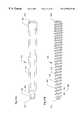
- Screw 410includes a root portion 412 that tapers at a constant rate from a leading end 414 to a trailing end 416 .
- the roothas a length of 2.383-inches and tapers from a radius of 0.184-inches near the trailing end to a radius of 0.098-inches near the leading end.
- a screw thread 418is formed on root portion 412 and extends from the leading end to the traling end thereof.
- Thread 418has a thread crest 420 at its radial outermost edge.
- the threadis terminated at the leading end and trailing end with a 45-degree taper.
- Thread 418has a pitch measured between consecutive thread crests which varies between a larger value near the leading end to a smaller value near the trailing end.
- the pitchchanges uniformly between the ends from a value of 0.097-inches at the leading end to a value of 0.066-inches at the trailing end.
- screw 410has a guide taper 422 at the leading end of the root portion.
- the guide taperhas a taper angle of approxately 15-degrees and serves to help maintain the leading end of the screw centered in the pilot hole in the bone in which it is installed.
- the guide taperextends along the root portion back from the 45-degree taper for a distance of 0.129-inches.
- Screw 410has a region 424 of constant outside diameter that extends back from the guide taper for a length of 0.090-inches with a diameter of 0.205-inches.
- a second region 426 of constant diameteris disposed adjacent the trailing end of the screw with a diameter of 0.256-inches for a length of 0.197-inches. Provision of regions 424 and 426 allows screw 410 to have a long length while reducing the amount of taper that would otherwise be required. It is important to maintain the radius as large as possible near the lead end to obtain adequate grip in this region. This is particularly important in the preferred application for screw 410 of ankle fusions because the amount of screw 410 engaged in the tibia may be limited.
- the region of constant diameter at the trailing endis also important because it provides a region for gripping the screw duing manufacture. Between the regions of constant diameter is a central region 428 in which the pitch and diameter of the screw change together.
- the central regionhas a length of 1.870-inches in the preferred embodiment.
- screw 410A significant difference between screw 410 and the previously described embodiment lies in the formation of the threads.
- the screw threadis cut with a tool with a flat face and outwardly sloping sides.
- the width of the facedetermines the spacing between the threads on the root portion, which was therefore constant along the length of the screw.
- screw 410in contrast, the longitudinal position of the tool along the root portion is changed from pass to pass as the screw is being turned.
- the toolfollows a first path.
- the toolis shifted longitudinally along the screw slightly at the same depth to increase the width of the inter-thread distance 428 on the root toward the leading end.
- Cutting the thread in this fashionallows a sharper thread to be produced while sfill obtaining the desired outside diameter taper and pitch variation.
- Sharper threadis beneficial because it leaves a smaller track in the bone which leaves more bone for subsequent threads to grip and makes the screw easier to dive in during installation.
- screw 410could be manufactured in a variety of lengths to accommodate different size patients. Moreover, for shorter screws, the region of constant outside diameter near the leading end may be eliminated without unduly compromising the grip of the leading threads. It should also be noted that shorter screws will typically taper at a greater angle.
- a holeis drilled up from the heel through the calcaneous and talus and into the distal end of the tibia.
- the screwis then driven into the hole to draw the tree bones together. With time, the pressure generated by the screw leads to fusion of the bones.
- the present screwis advantageous for this operation because it can be mounted sub-surface since it does not have a head. Furthermore, the screw offers excellent grip and controllable compression when compared with standard lag screws.
- screw 410preferably is cannulatd to provide improved stability during installation.
Landscapes
- Health & Medical Sciences (AREA)
- Surgery (AREA)
- Life Sciences & Earth Sciences (AREA)
- Orthopedic Medicine & Surgery (AREA)
- Biomedical Technology (AREA)
- Public Health (AREA)
- Veterinary Medicine (AREA)
- Engineering & Computer Science (AREA)
- Nuclear Medicine, Radiotherapy & Molecular Imaging (AREA)
- Heart & Thoracic Surgery (AREA)
- Medical Informatics (AREA)
- Molecular Biology (AREA)
- Animal Behavior & Ethology (AREA)
- General Health & Medical Sciences (AREA)
- Dentistry (AREA)
- Oral & Maxillofacial Surgery (AREA)
- Neurology (AREA)
- Surgical Instruments (AREA)
Abstract
Description
This application is a continuation-in-part of U.S. patent application Ser. No. 09/034,046, filed Mar. 3, 1998, now U.S. Pat. No. 5,964,768, which is a continuation-inpart of Ser. No. 08/781,471, filed Jan. 10, 1997, now U.S. Pat. No. 5,871,486, and a continuation-in-part of PCT application Ser. No. US94/00738, filed Jan. 19, 1994. In turn, application Ser. No. 08/781,471 is a continuation-in-part of application Ser. No. 08/506,469, filed Jul. 25, 1995, now abandoned, which is a continuation-in-part of Ser. No. 08/332,445, filed Oct. 31, 1994, now U.S. Pat. No. 5,562,672, which is a continuation of application Ser. No. 08/007,196, filed Jan. 21, 1993, now abandoned. All of the above patents and applications are hereby incorporated by reference.
The present invention relates generally to a bone screw for drawing together bone fragments separated by a fracture and more particularly to such a screw which draws the bone fragments together as a result of different-pitched threads on the screw.
In healing bone fractures it is desirable to compress the fractures so that the fractured surfaces are pressed against one another. In the prior ark bone screws have been used to draw the fractured surfaces together and thereby optimize the healing process.
A number of prior art bone screws have been constructed in a fashion resembling wood screws. For example, some prior art bone screws include a threaded distal portion and a head with a relatively long unthreaded shank disposed between the head and the distal portion. A drill is used to create a bore through the fracture and the screw is threaded into the remote bone fragment with the head of the screw compressing the near fragment tightly against the remote bone fragment.
Other bone screws are threaded along the length thereof thus requiting a first drill bit to create a bore in both bone fragments extending across the fracture and a second bit to drill a larger bore in the near bone fragment so that the screw threads do not engage the near bone fragment Thereafter, the screw is tightened in the same manner as described above in connection with the screw having an unthreaded shank, thereby compressing the fragments together.
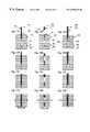
The operation of two prior art headed lag screws is illustrated in FIGS. 8A-10D. The operation of a lag screw A1with a head B1, and a shank C1is shown in FIGS. 8A-D. Shank C1of screw A1includes threads D1at the distal end and an unthreaded region E1proximal to head B1. The pitch of threads D1is constant. FIG. 8A shows screw A1partially engaged in a bore F1in a near bone fragment G1. The diameter of bore F1is less than the diameter of threads D1and therefore the threads engage the walls of the bore as the screw is twisted in. FIG. 8B shows screw A1as it starts threading into a bore H1in a remote bone fragment I1. At this point threads D1are engaged in both bores and moving forward at the same speed in both fragments so no compression between the fragments is achieved. Head B1has reached the top of fragment G1in FIG. 8C, as indicated schematically by the radiating “force” lines. Since threads D1are no longer engaged in fragment G1, screw A1rotates freely in the fragment without being drawn forward therein Subsequent rotation of screw A1draws fragment I1further up the screw. Because head B1prevents fragment G1from moving further up screw A1, fragment I1is drawn up against fragment G1and compression between the fragments is achieved as shown in FIG. 8D, with the head pulling down on the near fragment and the threads pulling up on the remote fragment.
The importance of the unthreaded region of screw A1is illustrated in FIGS. 9A-d. A lag screw A2including a head B2and a shank C2is shown partially engaged in a bore F2in a near fragment G2in FIG.9A. Shank C2includes threads D2running the entire length with no unthreaded region such as E1on screw A1. Rotating screw A2causes it to be drawn through fragment G2and pass into a bore H2in a remote fragment I2, as shown in FIG.9B. Further rotation of screw A2brings head B2down against the upper surface of fragment G2. See FIG.9C. At this point, threads D2are still engaged in bore F2of fragment G2and the interaction of the head on the surface of fragment G2impedes the further rotation of screw A2. To have additional rotation, head B2would have to be drawn down into fragment G2or the portion of threads D2in fragment G2would have to step out. Therefore a fully threaded screw, such as screw A2, would not be preferred for use in the fragment and bore configuration of FIGS. 9A-D.
The proper bore configuration for using screw A2is illustrated in FIGS. 10A-D. As shown in FIG. 10A, bore F2in fragment G2is enlarged to allow threads D2of screw A2to pass freely through the bore. Screw A2therefore slips into bore F2until it reaches fragment I2. At that point threads D2engage the walls of bore H2and draw screw A2down into fragment I2. See FIGS. 10B-C. When head B2reaches the upper surface of fragment G2, further rotation causes fragment I2to be drawn up into contact with fragment G2as shown in FIGS. 10C-D. No binding occurs between head B2and reads D2in the near fragment because of the large bore in fragment G2, and the screw functions as intended to draw the two fragments together.
FIGS. 11A-12D illustrate the effect of substituting headless screws in the place of lag screws A1and A2. FIG. 11A, in particular, shows a headless screw A3partially installed in a bore F3in a near fragment G3. Screw A3includes threads D3extending along its entire length The pitch of threads D3is constant. FIG. 11B shows screw A3extending through fragment G3and just entering a bore H3in a remote fragment I3. FIG. 11C shows screw A3advanced further into fragment I3. It should be noted that, since the pitch of threads D3is constant, screw A3moves forward in fragments G3and I3by the same amount with each rotation. As shown in FIG. 11D, screw A3will pass through both fragments without altering their relative spacing or compressing them together. Thus, a headless screw such as screw A3will not work to draw the fragments together in the same way as lag screws A1and A2.
A variation of screw A3is shown at A4in FIG.12A. Screw A4includes threads D4of constant pitch extending along its entire length and differs from screw A3in that it tapers from a smaller outside diameter at the leading end to a larger outside diameter at the trailing end. Screw A4is shown because it incorporates tapering which is one of the features of the present invention, however, it is unknown whether such a screw is found in the prior art Screw A4is shown partially installed in a bore F4in a near fragment G4in FIG.12A. As screw A4is rotated, it moves through fragment G4and into a bore H4in a remote fragment I4, as shown in FIG.12B. Subsequent rotation simply carries screw A4further into and through fragment I4without any effect on the spacing between the fragments. See FIGS. 12C-D. With a constant pitch Dread, such as found on thread D4, the taper does not facilitate compression. Taper may, however, make a screw easier to start in a small pilot hole or even without a pilot hole. The threaded portion of many wood screws follows this general format, tapering to a sharp point, to allow installation without a pilot bole.
It can be seen from the above discussion that a headless screw of constant pitch does not achieve the desired compressive effect between the two fragments as win a lag screw with a head. It is, however, possible to draw two fragments together with a headless screw if it has valuing pitch. FIG. 13A shows a headless screw As with threads D5formed along its entire length. Such a screw is shown in U.S. Pat. No. 146,023 to Russell. The pitch of threads D5varies from a maximum at the leading end to a minimum at the trailing end It is expected that such a screw moves forward upon rotation in a fragment according to the approximate average pitch of the threads engaged in the fragment. Screw A5is shown in FIG. 13A with the leading threads engaged in a bore F5in a near fragment G5. Rotation of screw A5causes it to move forward into and through fragment G5and into a bore H5in a remote fragment I5, as shown in FIG.13B. Additional rotation after the leading threads engage fragment I5causes the two fragments to be drawn together. See FIGS. 13C-D. This is because the average pitch of the threads in fragment I5is greater than the average pitch of threads in fragment G5. Since the screw moves forward in each fragment with each 360° rotation by an amount roughly equal to the average pitch of the threads in that fragment, each rotation will move the screw forward further in fragment I5than in fragment G5. This effect will gradually draw the fragments together as the screw moves forward. Depending on the initial spacing between the fragments, they can make contact either before or after the trailing end of the screw has entered fragment G5. It should be noted that screw A5, in contrast to constant pitch screws such as screws A1and A2, can be used to separate fragments G5and I5by simply reversing the rotation.
One drawback of a screw such as shown in Russell is the stopping or reaming of the female threads created in the bore by the leading threads as the trailing threads follow. Because the pitch changes along the length of the screw, no thread exactly follows the thread directly in front of it Rather, each thread tends to cut its own new path which only partially overlaps the path of the thread ahead of it Thus, the trailing threads tend to ream out the female threads in the bore made by the leading threads. This effect reduces the grip of the trailing threads and therefore the overall compressive force available to urge the fragments together.
FIG. 14A shows a headless screw A6, such as disclosed in U.S. Pat. No. 4,175,555 to Herbert, that offers one solution to the problem of reaming of threads. As noted in the Herbert patent, bone screws having heads suffer from several disadvantages including concentrated loads beneath the screw head and the protrusion of the screw head itself after the screw is installed. Several other shortcomings of the standard type of bone screw are detailed in the Herbert patent.
Screw A6, as per Herbert, includes a shank C6with leading threads J6at the leading end, trail threads K6at the trailing end and an unthreaded region E6separating the leading and trailing threads. Threads J6and K6each have fixed pitch, but leading threads J6have a larger pitch and smaller outside diameter than trailing threads K6. FIG. 14A shows leading threads J6of screw A6installed in a bore F6of a near fragment G6. It should be noted that threads J6do not engage the walls of bore F6, the bore having been bored large enough to allow leading threads J6to pass freely. As the screw moves forward, the leading threads engage a bore H6in a remote fragment I6. See FIG.14B. The diameter of bore H6is adapted so that leading threads J6engage the walls. Meanwhile, at the trailing end of the screw, trailing threads K6start to engage the walls of bore F6, which has been bored to an appropriate diameter therefor.
As soon as trailing threads K6are engaged in bore F6and leading threads J6are engaged in bore H6, the two fragments start drawing together. See FIG.14C. Further rotation of screw A6completes the process of moving the two fragments together as shown in FIG.14D. Screw A6operates on the same general principle as screw A5, except that the average pitch of the threads in the remote and near fragments is simply the pitch of the leading and ting threads, respectively. For instance, if the pitch of the leading threads is 0.2 inches and the pitch of the trailing threads is 0.1 inches, each rotation of screw A6will move it 0.2 inches further into fragment H6, but only 0.1 inches further into fragment I6, thus moving the fragments 0.1 inches closer together.
The Herbert screw overcomes at least one of the drawbacks of the Russell screw, the reaming of female threads by subsequent threads on the screw, but at the same time suffers from a number of other disadvantages. In the Herbert screw, the leading threads have a smaller diameter than the trailing threads. This is necessary to permit the leading threads to pass through the relatively large bore in the near bone fragment and engage the smaller bore in the remote bone fragment. The larger trailing threads then engage the larger bore in the near bone fragment As a result of this arrangement, any stripping of the threads cut into the bones during installation of the screw occurs in the remote bone. If the stripping occurred in the bore in the near bone fragment, a screw having a head thereon could still be used to compress the fracture even though the near bore was stripped; however, when stripping occurs in the bore in the remote bone, a standard screw with the head thereon cannot be used and another bore must be drilled.
Further, the Herbert screw must be correctly positioned, i.e., it is imperative that the fracture intersect the unthreaded central portion of the Herbert bone screw when the same is installed. Thus, the Herbert screw is not suitable for treating fractures that are very near the surface of the bone where the hole is to be drilled In addition, because the Herbert screw is not threaded entirely along the length thereof the purchase obtained by the screw in the bone is not as good as with a screw threaded along the entire length. Also, two bores of different sizes must be drilled to install the Herbert screw rather than a single bore.
Yet another problem with the Herbert screw is the stripping that can occur if additional tightening occurs after the screw has drawn the bone fragments together. While the bone fragments are being drawn together, trailing threads K6all follow a single path through the near fragment Similarly, leading threads J6all follow a single path through the remote fragment. When, however, the bone fragments make contact, the two sets of threads can no longer move independently. Further rotation of the Herbert screw after contact between the fragments can cause the leading threads to strip out as they attempt to move forward through the distal bone fragment faster than the trailing threads will allow. SeeThe Herbert Bone Screw and Its Applications in Foot Surgery, The Journal of Foot and Ankle Surgery, No. 33, Vol 4., 1994, pages 346-354 at page 346, which reports on a study that found compression of 10 kg after only two complete turns of the trailing threads engaged in the near bone fragment Each subsequent revolution lead to a decrease in compressive force. Thus, care must be taken not to over-tighten the Herbert screw.
In addition to drawing two bone fragments together to repair fractures, it is sometimes desirable to draw together two bones for fusing the same together in connection with arthrodesis of the interphalangeal joints. This procedure is sometimes indicated with symptoms of pain or instability in the finger joints. The purpose is to immobilize and draw together adjacent bones across a joint to cause them to fuses together thereby preventing further movement at the joint.
In one prior art procedure for immobilizing the distal interphalangeal joint (DIP), axial bores are drilled in the particular surfaces of the distal and proximal phalanges. The bore in the distal bone is sufficiently large to receive without threading a screw which is inserted therein via an incision in the tip of the finger. The screw threadably engages the bore in the proximal bone and when the screw head is tightened against the distal end of the distal bone, the two bones are compressed together. After several weeks, the bones fuse together. A second procedure to remove the screw must be performed because the head of the screw will cause discomfort in the finger pad if the screw is not removed.
This procedure is undesirable because it requires two separate surgeries. Katzman, et al.,Use of a Herbert Screw for Interphalangeal Joint Arthrodesis, Clinical Orthopedics and Related Research, No. 296 pages 127-132 (November 1993), describes use of the screw disclosed in the Herbert patent in procedures for interphalangeal joint arthrodesis.
Many of the above-discussed disadvantages associated with using a Herbert screw to compress a fracture are also present when the Herbert screw is used for interphalangeal joint arthrodesis.
It would be desirable to provide a headless bone screw which overcomes the disadvantages associated with the Herbert bone screw, as well as other prior art bone screws.
A bone screw for drawing together bone fragments separated by a fracture includes a root portion having a leading end and a trailing end. The leading end has a smaller diameter than the trailing end. A screw thread is formed on the root portion between the leading and trailing ends and has a pitch which varies along the length thereof, having a larger pitch near the leading end and a smaller pitch near the filing end. The thread is adapted to thread in the cancellous material of the respective bone fragments to be joined by the screw. Means are provided on the trailing end of the root portion to accommodate a tool for driving the screw. The present invention also contemplates a method for drawing together bone fragments separated by a fracture.
The foregoing and other objects, features and advantages of the invention will become more readily apparent from the following detailed description of a preferred embodiment which proceeds with reference to the drawings.
FIG. 1 is an enlarged side elevation view of a bone screw constructed in accordance with the present invention;
FIG. 1A is a view of the screw of FIG. 1 shown partially in cross section;
FIG. 2 is an end view of the bone screw of FIG. 1;
FIG. 3 is a drawing illustrating the outside diameter of the screw;
FIG. 4 is a drawing illustrating the diameter of the root portion of the screw;
FIG. 5 is a cross-sectional view of a bone screw constructed in accordance with the present invention installed in a bone to draw a fracture together;
FIG. 6 is a side elevation view of a bone screw constructed in accordance with the present invention which may be used for interphalangeal joint arthrodesis;
FIG. 7 is a view of the bone screw of FIG. 5 installed in a distal interphalangeal joint with the bones forming the joint as shown in cross-section;
FIGS. 8A-14D show the operation of various screws to compress two bone fragments together,
FIGS. 15A-D show the operation of a screw constructed according to an alternative embodiment of the present invention to compress two bone fragments together;
FIGS. 16A-B are detailed views of the screw shown in FIGS. 15C and 15D, respectively;
FIG. 17A is a side elevation view of a bone screw constructed according to an alternative embodiment of the present invention;
FIG. 17B is a representation of the side profile of a root portion of the screw of FIG. 17A;
FIG. 17C is a representation of the outside diameter of the screw of FIG. 7A;
FIG. 18A is a side elevation view of a bone screw constructed according to a fourth embodiment of the present invention;
FIG. 18B is a representation of the side profile of a root portion of the screw of FIG. 18A;
FIG. 18C is a representation of the outside diameter of the screw of FIG. 8A;
FIG. 19 is an enlarged side elevation view of a bone screw constructed in accordance with an alternative embodiment of the present invention;
FIG. 19A is a view of the screw of FIG. 19 shown partially in cross section;
FIG. 20 is an end view of the bone screw of FIG. 19;
FIG. 21aillustrates the outside diameter and root profile of an alternative embodiment of the present invention; and
FIG. 21bis an elevational view of the screw of FIG. 21a.
Indicated generally at10 in FIGS. 1 and 1A is a bone screw constructed in accordance with the presentinvention Bone screw 10 is centered on alongitudinal axis 11. The length ofscrew 10 as measured alongaxis 11 is 0.394 inches in the present embodiment of the invention. The bone screw includes aroot portion 12 having acontinuous screw thread 14 formed thereon.
A similarly tapering leadingthread 30 also has acrest 32 which varies in height over a first partial time ofscrew thread 14 so as to form an angle of substantially 45° withaxis 11 as illustrated in FIG.3.
The crest ofscrew thread 14 between trailing and leadingthreads thread 14. In the present embodiment of the invention, the outside diameter defined by the crest ofthread 14 between the leading and trailing threads forms anangle 34, in FIG. 3, of approximately 1.43° with respect to anaxis 35 extending from the radially outermost portion ofthread 14 parallel toaxis 11. In the present embodiment of the invention, the diameter of the radially outermost portion ofthread 14 is approximately 0.138 inches.
The pitch ofthread 14, i.e., the distance from one point on the thread to the corresponding point on an adjacent thread measured parallel toaxis 11, decreases between the leading and trailing ends of the screw. It should be noted that the term pitch is also sometimes used to refer to the number of threads per unit length, i.e., 20 threads per inch This alternative definition is simply the inverse of the definition chosen for use in this application. The distinction is important to remember for proper understanding of the subsequent description because the screw of the present invention relies on varying pitch to achieve its function.
In the embodiment of the invention shown in FIGS. 1 and 1A, the distance between the uppermost portion ofcrest 32 and acorresponding crest portion 36 is 0.04964 inches. The distance between the uppermost portion ofcrest 26 and acorresponding crest portion 38 is 0.04748 inches. In the present embodiment of the invention, the pitch change per revolution is approximately 0.00036 inches.
The pitch depth, i.e., the distance between the crest and the radially outer surface ofroot portion 12 similarly varies along the length of the screw. In the present embodiment of the invention, the pitch depth where leadingthread 30 joins the remainder ofscrew thread 14 is approximately 0.0302 inches. The pitch depth where trailingthread 24 joins the remainder ofthread 14 is approximately 0.0240 inches.
The decrease in pitch depth between the leading end and trailing end of the screw can be seen by comparing FIG.3 and FIG. 4 whereinroot portion 12 tapers more sharply from the trailing to the leading end of the screw than does the change in crest height as shown in FIG.3. In the present embodiment of the invention, the outside diameter ofroot portion 12 between leading and talk ends,16,18, respectively, forms anangle 40, in FIG. 4, of approximately 2.5° with respect to anaxis 42 extending from the radially outermost portion of trailingend 18 parallel toaxis 11.
Ahex socket 44 is formed on the trading end ofscrew 10 to accommodate a driver as will be hereinafter further explained in connection with a description of the procedure in which the screw is used to draw opposing fragments of a fractured bone together.
An alternative embodiment of the screw of the present invention is shown generally at410 in FIGS. 19 and19A Screw 410 includes aroot portion 412 on which is formed athread 414.Thread 414 extends from aleading end 416 to a trailingend 418 and includes aland 474. The pitch ofthread 414 at the leading end is 0.055 inches and the pitch at the tang end is 0.035 inches. The land varies from 0.010 inches to 0.004 inches overt the same range.Thread 414 includes a cuttingflute 415 near the leading end to facilitate the cutting of female threads as the screw is installed. Both the outside diameter ofthread 414 and root412 taper from a smaller value at the leading end to a larger value at the bailing end. See FIGS. 21-22. The root diameter tapers from 0.062 inches to 0.122 inches, while the outside diameter tapers from 0.130 inches to 0.156 inches. The length ofscrew 410 is 0.689 inches.
Screw410 also includes anaxial bore 425 which extends from the leading end to the trailing end.Bore 425 is adapted to receive a stiff guide wire, not shown, which facilitates installation ofscrew 410. Ahex socket 444 is formed at the trailing end to allow the screw to be driven by an hex wrench See FIG.20.
Turning now to FIG. 5, illustrated therein is afracture 46 which separates adjacent bone fragments48,50.Screw 10 is illustrated installed in abore 52 which extends through bone fragments48,50 acrossfracture 46.
In installingscrew 10, a surgeon first drills bore52 across bone fragments48,50 as shown The bit may be a conventional cylindrical bone bit or may comprise a bit having a slight taper from the leading to the trailing end thereof. Thereafter, the surgeon inserts a tool (not shown) having a hex driver extending therefrom which is connectable tohex socket 44 for screwingscrew 10 intobore 52.Bore 52 is of a size to just receive leadingend 16 ofscrew 10. As soon asnose portion 22 is received within the bore, torque is applied using the tool inserted intohex socket 44 thereby causing leadingthread 30 to cut into the boneadjacent bore 52.
In the view of FIG. 5, screw10 is hatched to show the path cut by leadingthread 30 afterscrew 10 is installed in the position illustrated in FIG.5. The path ofthread 30 is depicted using hatching, like hatching54,56,58 which indicates the position of the path cut by leadingthread 30 relative to succeeding threads of the screw.Hatching 60 depicts the actual position of the thread onscrew 10 androot 12. It is to be appreciated that hatching54,60 are not used in FIG. 5 to depict different structure, which is unitary as illustrated in FIG. 1, but to depict relative positions of the path cut by leadingthread 30 in the actual position of subsequent threads in the installed screw.
Because of the decreasing pitch along the length of the screw, each successive thread received in the path cut bythread 30 exerts pressure against the right side (as viewed in FIG. 5) of the path cut bythread 30 thereby tending to compress the bone along the length of the screw. As can be seen in FIG. 5, by the time the screw is fully installed, trailingthread 24 compresses a substantial amount of bone when it is received in the path cut bythread 30. This tends to drawbone fnents fracture 46 thereby promoting healing of te fracture.
As can be appreciated from the view of FIG. 5, the thread taper is important for two reasons. First, each succeeding portion of the thread is spaced further radially outwardly as a result of the taper and therefore the outer portion of each thread (that portion closely adjacent the crest) cuts into new bone which was not cut by the preceding thread This provides a much better purchase than would a thread having a continuously varying pitch with constant diameter. In such a configuration, each succeeding thread cuts additional bone within the generally cylindrical volume defined by the outside diameter of the threads. The outer portion of each thread (that portion closely a4jacent the crest) therefore cuts into bone uncut by the preceding thread.
The tapered root is also advantageous in that the radially outer surface of the root, i.e., that portion between adjacent threads, is tightly urged against uncut bone defining the wall ofbore 52. It is desirable to maximize the surface area ofscrew 10 urged against adjacent bone, rather than a space cut by a thread, to increase purchase of the screw.
The details of the operation of the screw of the present invention, as currently understood, may be better appreciated by examination of FIGS. 15A-D and FIGS. 16A-B and the following description FIGS. 15A-D illustrate the operation ascrew 310 to draw together and joinbone fragments screw 310 partially installed in abore 349 inbone fragment 348.Screw 310 is shown just entering abore 351 inbone fragment 350 in FIG.15B. Subsequent rotation ofscrew 310 starts the process of drawing the bone fragments together as shown in FIGS. 15C-D.
FIG. 16A shows the interaction of athread 314 inbores screw 310 is positioned therein as shown in FIG.15C. In FIG. 16A aleading end 316 ofscrew 310 is engaged inbore 349. Each revolution of thethread 314 is labelled for reference in the subsequent discussion, from thread T1 at the leading end to thread T23 at the trailing end.
As the screw moves through bone rents348 and350,thread 314 will cut a matingfemale thread 353. However, because the pitch ofthread 314 changes along the length of the screw,female thread 353 will not precisely matchthread 314 ofscrew 310 along its entire length. In particular, since subsequent threads will not track in the same path as the preceding threads, a pattern of leadinggaps 355 and trailing gaps357 will evolve betweenfemale thread 353 andscrew thread 314 as the screw moves forward in the bores.
The screw will move forward in the bone fragment with rotation at a rate that is a function of the competing forces from all of the threads engaged in the bore. The rate will correspond to an effective pitch of the threads in the bore and will be equal to the pitch of the screw at aneffective pitch point 359 along the portion of the screw engaged in the fragment. As more of the screw enters the bore, the effective pitch point will move back along the screw and further into the bone fragment. Once the screw extends completely through the bone fragment, the location of the effective pitch point will stabilize at a relatively constant location in the bone fragment, simply moving back along the screw at the rate the screw moves forward in the bore. The threads ahead of the effective pitch point, which will be referred to as theplling threads 371, will have greater pitch than the effective pitch. Similarly, the threads behind the effective pitch poit, or draggingthreads 373, will have a pitch that is smaller than the effective pitch. In FIG. 16A the pulling threads infragment 348 are T1-T4and the dragging threads are T5and T6.
Each rotation of the screw will move it forward infragment 348 by an amount corresponding to the present value of the effective pitch. In FIG. 16A the effective pitch will be equal to the pitch ofthread 314 between threads T4and T5. Starting at the leading end, thread T1. will always be cutting a new thread path in the fragment, so no gap will form around it. Thread T2, however, will attempt to follow the track of thread T1infragment 348, which would carry it forward by an amount equal to the pitch between thread T1and T2. Since, however, the screw will only move forward by the effective pitch, i.e., the pitch between threads T4and T5, thread T2can only move forward by the same amount This causes thread T2to pull back against the surrounding bone and creates a leading gap in front that thread. Similarly, thread T3will attempt to move into the position of thread T2, but will be held back from moving as far forward as its pitch would indicate, thus creating a leading gap as thread T3is pulled back against the surrounding bone. Behind the effective pitch point, thread T6will attempt to move into the prior position of thread T5, but will be dragged forward somewhat, leaving a trailing gap.
The pattern of leading and trading gaps created byscrew 310 inbone fragment 350 is also shown in FIG.16A.Bone fragment 350 includes leadinggaps 361 and trailing gaps363 similar to those found inbone fiagment 348. However, because more of the screw has moved throughbone fragment 350, the gaps have evolved to a greater extent The earlier position ofscrew 310 infragment 350 is shown in dotted lines in FIG. 16A to illustrate the evolution of the threads as the screw moves forward.
In the earlier position ofscrew 310, the effective pitch point falls at approximately thread T8. With the screw positioned as shown, the effective pitch point is at approximately thread T16, the screw having completed approximately 8 revolutions between the two positions. The current and prior screw positions are aligned ateffective pitch point 367 infragment 350 based on the assumption thatthread 314 will track through this point uniformly. The evolution of the position of threads behind and ahead of the effective pitch point can thus be seen by comparing the prior position with the current position.
Leadinggaps 361 have a slopingupper surface 365, which is a result of the gradual expansion of the outside diameter ofthread 314 toward the trailing end of the screw.Upper surface 365 represents a line from the prior position of the thread to the position as shown. Asthread 314 at a given point in the bone fragment is held back, it simultaneously expands in diameter. This effect preventsthread 314 from completely reaming out the female thread in the bone fragment, as discussed above. Without the taper, slopingupper surface 365 would be flat and as soon as the width of the gap grew to equal the spacing between the threads, there would be no purchase left for subsequent threads along a portion of the bore.
Once the leading end ofscrew 310 has passed through bone Went351 the effective pitch point remains at a relatively constant position along the bore for the remainder of the screw. If the pitch change per revolution is dP and the effective pitch points are separated by N threads, then the bone fragments will be drawn together by a distance N times dP for every revolution of the screw. Inscrew 310, dP=0.0008 inches and the effective pitch points are separated by approximately 11 threads, therefore the gap between the bone fragments will close by about 0.009 inches per revolution.
It is thought that the effective pitch point will be somewhat behind the geometric middle of the portion of the screw engaged in the bore as shown in FIG.16A. Because bone becomes less dense near the center in the cancellous portion, the threads nearer to the surface in the cortex are expected to have greater effect. A1so, the lads nearer the surface are of larger diameter because of the taper in the outside diameter of the thread.
The other factor tending to cause the pitch point to be closer to the surface of the bone relates to balancing the amount of bone displaced as the leading and trailing gaps are formed. As shown in FIG. 16A, the pullingthreads 371, which have pitch greater than the effective pitch, are held back from moving as far forward with each rotation as their pitch would indicate. Likewise, draggingthreads 373 are drawn forward faster tand their pitch would dictate. This effect creates leadinggaps 355 in front of pullingthreads 371 as20 they pull against the surrounding bone. Similarly, trailing gaps357 form behind draggingthreads 373 as they are dragged forward through the surrounding bone.
Since the leading and tailing gaps are formed in opposition to one another, it is reasonable to assume that they will evolve at a relatively balanced rate. Combining this assumption with the fact that the effective pitch point is constantly moving forward in the bone fragment as the screw enters, suggests that the effective pitch point will be behind the geometric middle of the portion of the screw in the bone fragment. Because the effective pitch point is moving forward in the bone fragment by approximately one-half the pitch change per revolution, the dragging threads will be dragged forward by approximately an extra one-half the pitch change per revolution for each revolution of the screw. The fact that the effective pitch point is moving forward means that the pulling threads are not held back as much as would be the case if the effective pitch point remained constant. If the movement of the two tbread regions through the bone are balanced, then the effective pitch point will not move forward in the bone fragment as rapidly as would otherwise be expected and the effective pitch point will lie behind the geometric middle.
FIG. 16B shows how the pattern of gaps changes once the two bone fragments have been drawn together. After the bone fragments meet, the pattern of gaps starts to evolve toward that found in a single fragment In particular, gaps form or increase on the leading side of all of the pulling threads ahead of an effective combinedpitch point 369, and on the traling side of all the dragging reads behind the effective combined pitch point. Near the joint between the fragments, the gaps will generally transition from leading to trailing and vice versa, because the dragging threads infragment 348 near the joint are converted to pulling threads after the joint closes. The pulling threads inftagment 350 likewise become dragging hireads after the fragments meet.
Rotation ofscrew 310 after the bone fragments have come together tends to increase the pressure in the joint between them. Additional rotation can be used to set the depth of the screw as desired. Since the outside diameter of the thread tapers, as described above, the screw can be driven in until the trailing end is below the surface of the bone without danger of stripping the female thread formed by the preceding threads, even if the bone fragments first meet with the trailing end protruding substantially. This is because subsequent thiads expand and cut into some new bone even as they partially ream the female threads left by preceding threads on the screw. This is in contrast to the Herbert screw, where, as discussed above, additional tightening after the fragments have come together can strip out the threads in the distal fagment and reduce compression. Since it is important in the preferred application of the present invention to have the trailing end of the screw below the surface of the bone, this is an important feature and advantage over prior art screws.
The tolerance in the screw of the present invention to further tightening after the fragments have come together is also important because it simplifies the installation process by eliminating the danger of over-tightening that must be guarded against when using the Herbert screw.
Turning now to FIG. 6, indicated generally at62 is a second embodiment of a bone screw constructed in accordance with the present invention.Bone screw 62 is sized and constructed for use in connection with intelphalangeal joint arthrodesis.Screw 62 includes a tapered root64 having athread 65 formed thereon from a leadingend 63 to a trailingend 67, a substantially cylindrical leadingextension 66 joined to the leading end and a substantiallycylindrical tailing extension 68 joined to the tailing end. The diameter of leadingextension 66 is slightly larger than root64 at leadingend 63, while the diameter ofrailing extension 68 is slihe* smaller than root64 at trailingend 67. The trailingextension 68 includes a hex socket (not visible), likehex socket 44 in FIG. 1A, formed on anend surface 70 thereof Leadingextension 66 includes a taperednose 72 formed on the forward end thereof In the present embodiment of the invention, screw62 is 1.259 inches in length with the threaded portion being 0.630 inches long and the diameter of leadingextension 66 being 0.05 inches. The trailing extension diameter is 0.100 inches. As is the case with the previously described embodiment, the pitch ofthread 65 decreases between the leading and trailing ends. in the embodiment of FIG. 6, aland 74 is formed in the crest ofthread 65 and decreases in width between the leading and trailing ends of the screw.
Turning now to FIG. 7, adistal phalanx 76 comprises the outermost bone of one of the four fingers. Aproximal phalanx 78 is adjacent thereto with a distal interphalangeal (DIP) joint80 being formed therebetween.
The joint includes a pair ofarticular surfaces Bores phalanxes articular surfaces phalanx 76 until the screw is positioned as shown in FIG.7.
A third embodiment of a screw constructed according to the present invention is shown generally at110 in FIG.17A.Screw 110 includes aroot portion 112 on which is formed acontinuous screw thread 114 and associatedland 174.Screw 110 includes aleading end 116 and a tailingend 118. Leading cuttingflutes 115 are fonned inthread 114 near leadingend 116 to help the thread self tap into the bone. A series oftig cutting flutes 117 are formed inthread 114 along the sides of the screw toward the trailing end. Trailing cuttingflutes 117 facilitate istallation and removal of the screw by helping to cut a thread path in the bone.Screw 110 may be formed with two sets of halig cutting flutes, one oriented to cut female threads upon insertion and another oriented to cut female threads upon removal of the screw, thus easing both installation and extraction. Ahex socket 144 is formed in the trailing end ofscrew 110 to receive a drive tool.
The construction ofconstant pitch portion 121 is considerably different from that ofvariable pitch portion 119. The pitch and outside diameter ofthread 114 are constant over the section of the screw formingconstant pitch portion 121.Root portion 112 continues to taper outward relative to the axs of the screw but at alesser angle 127 of 1.57° over the constant pitch portion. The width ofland 174, i.e., the flat at the crest of the thread, which decreases from the leading end over the variable pitch portion, increases over the length of the constant pitch portion toward the trailing end.Land 174 starts at the leading end at 0.008 inches and decreases to 0.002 inches at the end of the variable pitch region.Land 174 starts to increase again moving back over the constant pitch portion, reaching a value of 0.006-0.007 inches at the traling end.
The constant pitch portion at the rear ofscrew 110 allows construction of a longer screw without the commensurate increase in diameter that would occur by extending the structure of the variable pitch portion. This is important where the screw is to be used in small bones that cannot accept a larger bore, but which require a longer screw. A longer screw may be required to reach deeper fractures or for use in fusing two bones together.Screw 110 is particularly suitable for use in distal interphalangeal fusions in the hand as described above.
A fourth embodiment of a screw constructed according to the present invention is shown at210 in FIG.18A.Screw 210 is generally similar to screw110 of FIG. 17A, and includes aroot portion 212, athread 214, aleading end 216 and a trailingend 218. Screw210 also includes avariable pitch portion 219 and aconstant pitch portion 221. See FIG.18B. The diameter ofroot portion 212 tapers at anangle 240 of 2.29° from 0.050 inches at the leading end to 0.106 inches at the trailing end. The outside diameter ofthread 214 tapers at anangle 234 of 1.20 from 0.110 inches to 0.140 inches over the same range. The overall length ofscrew 210 is 0.787 inches.
The principal difference betweenscrews screw 210, neither the root portion nor the outside diameter of the thread is tapered in the constant pitch region. See FIGS. 18B-C. Screw 210 is designed, likescrew 110, to have additional length without additional thickness. If additional length is desired, it is possible to formscrew 210, or screw110, with leading and/or trailing extensions such as found onscrew 62 in FIG.6.
Screw210 also varies fromscrew 110 in that it includes anaxial bore 225. Axial bore225 permits screw210 to be guided into the bone on a stiff wire to facilitate positioning and prevent the screw from wandering off axis as it is driven in.
It should be noted that the length, nwnber of threads, pitch, pitch change per revolution and the various diameters are not critical to the present invention and can be varied without departing from the spirit of the invention. Such parameters are chosen to suit the particular use to which the screw is applied.
A screw according to the present invention particularly adapted for use in ankle fusions is shown genelaly at410 in FIGS. 21a-b.Screw 410 includes aroot portion 412 that tapers at a constant rate from aleading end 414 to a trailingend 416. In the prefenred embodiment the root has a length of 2.383-inches and tapers from a radius of 0.184-inches near the trailing end to a radius of 0.098-inches near the leading end.
Ascrew thread 418 is formed onroot portion 412 and extends from the leading end to the traling end thereof.Thread 418 has athread crest 420 at its radial outermost edge. As with the previously described embodiments, the thread is terminated at the leading end and trailing end with a 45-degree taper.Thread 418 has a pitch measured between consecutive thread crests which varies between a larger value near the leading end to a smaller value near the trailing end. Preferably, the pitch changes uniformly between the ends from a value of 0.097-inches at the leading end to a value of 0.066-inches at the trailing end.
In contrast to the previously described screws,screw 410 has aguide taper 422 at the leading end of the root portion. The guide taper has a taper angle of approxately 15-degrees and serves to help maintain the leading end of the screw centered in the pilot hole in the bone in which it is installed. The guide taper extends along the root portion back from the 45-degree taper for a distance of 0.129-inches.
A significant difference betweenscrew 410 and the previously described embodiment lies in the formation of the threads. in particular, in the previously described embodiments, the screw thread is cut with a tool with a flat face and outwardly sloping sides. In the previous embodiments, the width of the face determines the spacing between the threads on the root portion, which was therefore constant along the length of the screw. By pulling the tool back from the axis of the screw and adjusting the pitch properly, the thread can be cut with a varying pitch and depth. However, with each pass of the tool along the screw, the tool follows the same longitudinal path in the thread but simply cuts closer to the root portion. The land at the crest is also increased near the leading end to allow for additional pitch gain near the leading end while maintaining a decreasing outside radius.
Inscrew 410, in contrast, the longitudinal position of the tool along the root portion is changed from pass to pass as the screw is being turned. In particular, in one pass down the screw thread, the tool follows a first path. In a subsequent pass the tool is shifted longitudinally along the screw slightly at the same depth to increase the width of theinter-thread distance 428 on the root toward the leading end. Cutting the thread in this fashion allows a sharper thread to be produced while sfill obtaining the desired outside diameter taper and pitch variation. Sharper thread is beneficial because it leaves a smaller track in the bone which leaves more bone for subsequent threads to grip and makes the screw easier to dive in during installation. As with previously descnrbed embodiments, it is important that the radius and depth of the threads near the leading end be sufficient to provide a grip on the bone which is comparable to the grip of the threads near the trailing end of the screw.
It should be understood thatscrew 410 could be manufactured in a variety of lengths to accommodate different size patients. Moreover, for shorter screws, the region of constant outside diameter near the leading end may be eliminated without unduly compromising the grip of the leading threads. It should also be noted that shorter screws will typically taper at a greater angle.
In the actual fusion, a hole is drilled up from the heel through the calcaneous and talus and into the distal end of the tibia. The screw is then driven into the hole to draw the tree bones together. With time, the pressure generated by the screw leads to fusion of the bones. The present screw is advantageous for this operation because it can be mounted sub-surface since it does not have a head. Furthermore, the screw offers excellent grip and controllable compression when compared with standard lag screws.
Although not shown in FIGS. 21a-b, screw410 preferably is cannulatd to provide improved stability during installation.
While the invention has been disclosed in its preferred form the specific embodiments thereof as disclosed and illustrated herein are not to be considered in a limiting sense because numerous variations are possible. Applicant regards the subject matter of his invention to include all novel and non-obvious combinations and subcombinations of the various elements, features, finctions, and/or properties disclosed herein. No single feature, finction, element, or properly of the disclosed embodiments is essential. The following claims define certain combinations and subcombinations which are regarded as novel and non-obvious. Other combinations and subcombinations of features, fimctions, elements, and/or properties may be claimed through amendment of the present claims or presentation of new claims in this or a related application. Such claims, whether they are broader, narrower, or equal in scope to the original claims, also are regarded as included within the subject matter of applicant's invention.
Claims (11)
1. A method of fusing a joint between two bones, comprising:
boring a hole through one of the bones across the joint therebetween and into the other bone;
placing the leading end of a screw into the hole, where the screw has a single continuous threaded region having a pitch that is larger toward a leading end of the screw and smaller toward a trailing end of the screw; and
driving the screw into the bone until the treaded region spans the joint.
2. The method of claim1, wherein the joint is an ankle.
3. The method of claim1, wherein the joint is phalangeal joint.
4. The method of claim1, wherein the screw includes an unthreaded leading end.
5. The method of claim1, wherein the screw includes an unthreaded trailing end.
6. The method of claim1, wherein the thread has a depth that is greater near the leading end of the screw and smaller toward the trailing end of the screw.
7. The method of claim1, wherein the thread has an outside diameter that tapers over at least the first few thread revolutions.
8. The method of claim1, wherein the thread has a region of constant diameter toward the trailing end.
9. The method of claim1, wherein the pitch is approximately fifty-percent larger toward the leading end than toward the trailing end.
10. The method of claim1, wherein the outside diameter of the threads has a conical truncation at the leading end of the threaded region.
11. The method of claim1, wherein the thread has a land, and the land is larger near the leading end than near the trailing end.
Priority Applications (5)
| Application Number | Priority Date | Filing Date | Title |
|---|---|---|---|
| US09/375,306US6299615B1 (en) | 1993-01-21 | 1999-08-16 | System for fusing joints |
| US11/329,368US8070786B2 (en) | 1993-01-21 | 2006-01-09 | System for fusing joints |
| US13/312,626US20120130433A1 (en) | 1993-01-21 | 2011-12-06 | Axial tension screw |
| US13/851,702US9161793B2 (en) | 1993-01-21 | 2013-03-27 | Axial tension screw |
| US14/885,951US20160038203A1 (en) | 1993-01-21 | 2015-10-16 | Axial tension screw |
Applications Claiming Priority (7)
| Application Number | Priority Date | Filing Date | Title |
|---|---|---|---|
| US719693A | 1993-01-21 | 1993-01-21 | |
| PCT/US1994/000738WO1994016636A1 (en) | 1993-01-21 | 1994-01-19 | Tapered bone screw with continuously varying pitch |
| US08/332,445US5562672A (en) | 1993-01-21 | 1994-10-31 | Tapered bone screw with continuously varying pitch |
| US50646995A | 1995-07-25 | 1995-07-25 | |
| US08/781,471US5871486A (en) | 1993-01-21 | 1997-01-10 | Variable pitch bone screw |
| US09/034,046US5964768A (en) | 1993-01-21 | 1998-03-03 | Tapered bone screw with continuously varying pitch |
| US09/375,306US6299615B1 (en) | 1993-01-21 | 1999-08-16 | System for fusing joints |
Related Parent Applications (3)
| Application Number | Title | Priority Date | Filing Date |
|---|---|---|---|
| US09/019,135Continuation-In-PartUS5976134A (en) | 1993-01-21 | 1998-02-05 | External fixator for repairing fractures |
| US09/034,046Continuation-In-PartUS5964768A (en) | 1993-01-21 | 1998-03-03 | Tapered bone screw with continuously varying pitch |
| US09/305,841Continuation-In-PartUS6017347A (en) | 1993-01-21 | 1999-05-05 | Wire clamp assembly |
Related Child Applications (2)
| Application Number | Title | Priority Date | Filing Date |
|---|---|---|---|
| US48307600AContinuation-In-Part | 1993-01-21 | 2000-01-14 | |
| US09/691,092DivisionUS6465387B1 (en) | 1999-08-12 | 2000-10-18 | Combined porous organic and inorganic oxide materials prepared by non-ionic surfactant templating route |
Publications (1)
| Publication Number | Publication Date |
|---|---|
| US6299615B1true US6299615B1 (en) | 2001-10-09 |
Family
ID=46256617
Family Applications (1)
| Application Number | Title | Priority Date | Filing Date |
|---|---|---|---|
| US09/375,306Expired - Fee RelatedUS6299615B1 (en) | 1993-01-21 | 1999-08-16 | System for fusing joints |
Country Status (1)
| Country | Link |
|---|---|
| US (1) | US6299615B1 (en) |
Cited By (104)
| Publication number | Priority date | Publication date | Assignee | Title |
|---|---|---|---|---|
| US6547564B1 (en)* | 1998-07-17 | 2003-04-15 | Astra Aktiebolag | Bone implant having circumferentially oriented roughness |
| US20030158557A1 (en)* | 2000-02-16 | 2003-08-21 | Cragg Andrew H. | Method and apparatus for spinal distraction and fusion |
| US6743233B1 (en) | 2000-08-02 | 2004-06-01 | Orthopaedic Biosystems, Ltd., Inc. | Medical screw and method of installation |
| US20040210227A1 (en)* | 2003-02-03 | 2004-10-21 | Kinetikos Medical, Inc. | Compression screw apparatuses, systems and methods |
| US20050113929A1 (en)* | 2000-02-16 | 2005-05-26 | Cragg Andrew H. | Spinal mobility preservation apparatus |
| US20050165402A1 (en)* | 2002-02-15 | 2005-07-28 | Taras John S. | Cannulated distraction pin for fracture fixation |
| US20060229622A1 (en)* | 1993-01-21 | 2006-10-12 | Huebner Randall J | System for fusing joints |
| US20060247641A1 (en)* | 2004-11-15 | 2006-11-02 | Paul Re | Method and apparatus for the repair of a rotator cuff (RTC) tendon or ligament |
| US7235079B2 (en) | 2004-11-18 | 2007-06-26 | Acumed Llc | Composite bone fasteners |
| US20070233124A1 (en)* | 2006-03-17 | 2007-10-04 | Nexa Orthopedics, Inc. | Compression pin with opposed threaded regions |
| US20070288024A1 (en)* | 2006-06-06 | 2007-12-13 | Sohrab Gollogly | Bone fixation |
| US20080213714A1 (en)* | 2005-11-11 | 2008-09-04 | Alexander Knoch | Rotary Furnace Burner |
| US20080241791A1 (en)* | 2007-03-31 | 2008-10-02 | Imtec Corporation | Implant thread design |
| US7500977B2 (en) | 2003-10-23 | 2009-03-10 | Trans1 Inc. | Method and apparatus for manipulating material in the spine |
| US20090192512A1 (en)* | 2008-01-28 | 2009-07-30 | Sommers Mark B | Bone nail |
| US20090228048A1 (en)* | 2008-03-10 | 2009-09-10 | Duncan Scott F M | Joint Fixation System For the Hand |
| US7601165B2 (en) | 2006-09-29 | 2009-10-13 | Biomet Sports Medicine, Llc | Method and apparatus for forming a self-locking adjustable suture loop |
| US7608092B1 (en) | 2004-02-20 | 2009-10-27 | Biomet Sports Medicince, LLC | Method and apparatus for performing meniscus repair |
| US7608098B1 (en) | 2004-11-09 | 2009-10-27 | Biomet Sports Medicine, Llc | Bone fixation device |
| US7608077B2 (en) | 2000-02-16 | 2009-10-27 | Trans1 Inc. | Method and apparatus for spinal distraction and fusion |
| US7736380B2 (en) | 2004-12-21 | 2010-06-15 | Rhausler, Inc. | Cervical plate system |
| US7749250B2 (en) | 2006-02-03 | 2010-07-06 | Biomet Sports Medicine, Llc | Soft tissue repair assembly and associated method |
| US7857830B2 (en) | 2006-02-03 | 2010-12-28 | Biomet Sports Medicine, Llc | Soft tissue repair and conduit device |
| US7905904B2 (en) | 2006-02-03 | 2011-03-15 | Biomet Sports Medicine, Llc | Soft tissue repair device and associated methods |
| US7905903B2 (en) | 2006-02-03 | 2011-03-15 | Biomet Sports Medicine, Llc | Method for tissue fixation |
| US7909851B2 (en) | 2006-02-03 | 2011-03-22 | Biomet Sports Medicine, Llc | Soft tissue repair device and associated methods |
| US7914539B2 (en) | 2004-11-09 | 2011-03-29 | Biomet Sports Medicine, Llc | Tissue fixation device |
| US7959650B2 (en) | 2006-09-29 | 2011-06-14 | Biomet Sports Medicine, Llc | Adjustable knotless loops |
| US8034090B2 (en) | 2004-11-09 | 2011-10-11 | Biomet Sports Medicine, Llc | Tissue fixation device |
| US8088130B2 (en) | 2006-02-03 | 2012-01-03 | Biomet Sports Medicine, Llc | Method and apparatus for coupling soft tissue to a bone |
| US8118836B2 (en) | 2004-11-05 | 2012-02-21 | Biomet Sports Medicine, Llc | Method and apparatus for coupling soft tissue to a bone |
| US8128658B2 (en) | 2004-11-05 | 2012-03-06 | Biomet Sports Medicine, Llc | Method and apparatus for coupling soft tissue to bone |
| US8137382B2 (en) | 2004-11-05 | 2012-03-20 | Biomet Sports Medicine, Llc | Method and apparatus for coupling anatomical features |
| US8197511B2 (en) | 2007-09-24 | 2012-06-12 | Miller M Todd | Suture anchor having a suture engaging structure and inserter arrangement |
| US8251998B2 (en) | 2006-08-16 | 2012-08-28 | Biomet Sports Medicine, Llc | Chondral defect repair |
| US8298262B2 (en) | 2006-02-03 | 2012-10-30 | Biomet Sports Medicine, Llc | Method for tissue fixation |
| US8303604B2 (en) | 2004-11-05 | 2012-11-06 | Biomet Sports Medicine, Llc | Soft tissue repair device and method |
| US8317825B2 (en) | 2004-11-09 | 2012-11-27 | Biomet Sports Medicine, Llc | Soft tissue conduit device and method |
| US8343227B2 (en) | 2009-05-28 | 2013-01-01 | Biomet Manufacturing Corp. | Knee prosthesis assembly with ligament link |
| US8361113B2 (en) | 2006-02-03 | 2013-01-29 | Biomet Sports Medicine, Llc | Method and apparatus for coupling soft tissue to a bone |
| US20130131678A1 (en)* | 2010-06-03 | 2013-05-23 | The University Of North Carolina At Chapel Hill | Threaded elastic intramedullary nails devices and methods |
| US20130187025A1 (en)* | 2012-01-19 | 2013-07-25 | Lloyd L. Lawrence | Cavity forming plug for concrete |
| US8500818B2 (en) | 2006-09-29 | 2013-08-06 | Biomet Manufacturing, Llc | Knee prosthesis assembly with ligament link |
| US8506597B2 (en) | 2011-10-25 | 2013-08-13 | Biomet Sports Medicine, Llc | Method and apparatus for interosseous membrane reconstruction |
| US8562645B2 (en) | 2006-09-29 | 2013-10-22 | Biomet Sports Medicine, Llc | Method and apparatus for forming a self-locking adjustable loop |
| US8562647B2 (en) | 2006-09-29 | 2013-10-22 | Biomet Sports Medicine, Llc | Method and apparatus for securing soft tissue to bone |
| US8574235B2 (en) | 2006-02-03 | 2013-11-05 | Biomet Sports Medicine, Llc | Method for trochanteric reattachment |
| US8597327B2 (en) | 2006-02-03 | 2013-12-03 | Biomet Manufacturing, Llc | Method and apparatus for sternal closure |
| US8632568B2 (en) | 2007-09-24 | 2014-01-21 | Stryker Corporation | Suture anchor having a suture engaging structure and inserter arrangement |
| US8652171B2 (en) | 2006-02-03 | 2014-02-18 | Biomet Sports Medicine, Llc | Method and apparatus for soft tissue fixation |
| US8652172B2 (en) | 2006-02-03 | 2014-02-18 | Biomet Sports Medicine, Llc | Flexible anchors for tissue fixation |
| US8672969B2 (en) | 2006-09-29 | 2014-03-18 | Biomet Sports Medicine, Llc | Fracture fixation device |
| US8771352B2 (en) | 2011-05-17 | 2014-07-08 | Biomet Sports Medicine, Llc | Method and apparatus for tibial fixation of an ACL graft |
| US8801783B2 (en) | 2006-09-29 | 2014-08-12 | Biomet Sports Medicine, Llc | Prosthetic ligament system for knee joint |
| US8840645B2 (en) | 2004-11-05 | 2014-09-23 | Biomet Sports Medicine, Llc | Method and apparatus for coupling soft tissue to a bone |
| US8858596B2 (en) | 2012-03-20 | 2014-10-14 | Stryker Corporation | Suture anchor having a suture engaging structure |
| US8936621B2 (en) | 2006-02-03 | 2015-01-20 | Biomet Sports Medicine, Llc | Method and apparatus for forming a self-locking adjustable loop |
| US8968364B2 (en) | 2006-02-03 | 2015-03-03 | Biomet Sports Medicine, Llc | Method and apparatus for fixation of an ACL graft |
| US8998949B2 (en) | 2004-11-09 | 2015-04-07 | Biomet Sports Medicine, Llc | Soft tissue conduit device |
| US9017381B2 (en) | 2007-04-10 | 2015-04-28 | Biomet Sports Medicine, Llc | Adjustable knotless loops |
| US9078644B2 (en) | 2006-09-29 | 2015-07-14 | Biomet Sports Medicine, Llc | Fracture fixation device |
| US9095444B2 (en) | 2009-07-24 | 2015-08-04 | Warsaw Orthopedic, Inc. | Implant with an interference fit fastener |
| US9149267B2 (en) | 2006-02-03 | 2015-10-06 | Biomet Sports Medicine, Llc | Method and apparatus for coupling soft tissue to a bone |
| US9161793B2 (en) | 1993-01-21 | 2015-10-20 | Acumed Llc | Axial tension screw |
| US9259217B2 (en) | 2012-01-03 | 2016-02-16 | Biomet Manufacturing, Llc | Suture Button |
| US9271713B2 (en) | 2006-02-03 | 2016-03-01 | Biomet Sports Medicine, Llc | Method and apparatus for tensioning a suture |
| US9314241B2 (en) | 2011-11-10 | 2016-04-19 | Biomet Sports Medicine, Llc | Apparatus for coupling soft tissue to a bone |
| US9357991B2 (en) | 2011-11-03 | 2016-06-07 | Biomet Sports Medicine, Llc | Method and apparatus for stitching tendons |
| US9370350B2 (en) | 2011-11-10 | 2016-06-21 | Biomet Sports Medicine, Llc | Apparatus for coupling soft tissue to a bone |
| US9381013B2 (en) | 2011-11-10 | 2016-07-05 | Biomet Sports Medicine, Llc | Method for coupling soft tissue to a bone |
| US9538998B2 (en) | 2006-02-03 | 2017-01-10 | Biomet Sports Medicine, Llc | Method and apparatus for fracture fixation |
| US9615822B2 (en) | 2014-05-30 | 2017-04-11 | Biomet Sports Medicine, Llc | Insertion tools and method for soft anchor |
| US9681960B2 (en) | 2014-05-16 | 2017-06-20 | Howmedica Osteonics Corp. | Guides for fracture system |
| US9700291B2 (en) | 2014-06-03 | 2017-07-11 | Biomet Sports Medicine, Llc | Capsule retractor |
| US9724149B2 (en) | 2013-03-07 | 2017-08-08 | Warsaw Orhtopedic, Inc. | Surgical implant system and method |
| US9757119B2 (en) | 2013-03-08 | 2017-09-12 | Biomet Sports Medicine, Llc | Visual aid for identifying suture limbs arthroscopically |
| US9801708B2 (en) | 2004-11-05 | 2017-10-31 | Biomet Sports Medicine, Llc | Method and apparatus for coupling soft tissue to a bone |
| US9814598B2 (en) | 2013-03-14 | 2017-11-14 | Quandary Medical, Llc | Spinal implants and implantation system |
| US9918826B2 (en) | 2006-09-29 | 2018-03-20 | Biomet Sports Medicine, Llc | Scaffold for spring ligament repair |
| US9918827B2 (en) | 2013-03-14 | 2018-03-20 | Biomet Sports Medicine, Llc | Scaffold for spring ligament repair |
| US9955980B2 (en) | 2015-02-24 | 2018-05-01 | Biomet Sports Medicine, Llc | Anatomic soft tissue repair |
| US10039543B2 (en) | 2014-08-22 | 2018-08-07 | Biomet Sports Medicine, Llc | Non-sliding soft anchor |
| US20180235670A1 (en)* | 2014-11-26 | 2018-08-23 | Ex Technology, Llc | Method and apparatus for joint fusion |
| US10136886B2 (en) | 2013-12-20 | 2018-11-27 | Biomet Sports Medicine, Llc | Knotless soft tissue devices and techniques |
| US10136929B2 (en) | 2015-07-13 | 2018-11-27 | IntraFuse, LLC | Flexible bone implant |
| US10154863B2 (en) | 2015-07-13 | 2018-12-18 | IntraFuse, LLC | Flexible bone screw |
| US10485595B2 (en) | 2015-07-13 | 2019-11-26 | IntraFuse, LLC | Flexible bone screw |
| US10499960B2 (en) | 2015-07-13 | 2019-12-10 | IntraFuse, LLC | Method of bone fixation |
| US10517587B2 (en) | 2006-02-03 | 2019-12-31 | Biomet Sports Medicine, Llc | Method and apparatus for forming a self-locking adjustable loop |
| US10575968B2 (en) | 2014-05-16 | 2020-03-03 | Howmedica Osteonics Corp. | Guides for fracture system |
| US10667923B2 (en) | 2016-10-31 | 2020-06-02 | Warsaw Orthopedic, Inc. | Sacro-iliac joint implant system and method |
| US10912551B2 (en) | 2015-03-31 | 2021-02-09 | Biomet Sports Medicine, Llc | Suture anchor with soft anchor of electrospun fibers |
| US11000325B2 (en) | 2018-02-27 | 2021-05-11 | Acumed Llc | Bone fastener with partially overlapping threads and a varying lead |
| US11259794B2 (en) | 2006-09-29 | 2022-03-01 | Biomet Sports Medicine, Llc | Method for implanting soft tissue |
| US11259792B2 (en) | 2006-02-03 | 2022-03-01 | Biomet Sports Medicine, Llc | Method and apparatus for coupling anatomical features |
| US11266453B2 (en) | 2018-09-21 | 2022-03-08 | DePuy Synthes Products, Inc. | Bone compression screws and related systems and methods |
| US11311287B2 (en) | 2006-02-03 | 2022-04-26 | Biomet Sports Medicine, Llc | Method for tissue fixation |
| US11344354B2 (en) | 2019-09-09 | 2022-05-31 | Warsaw Orthopedic, Inc. | Surgical instrument and method |
| US20220330993A1 (en)* | 2019-09-27 | 2022-10-20 | Pravin Salunke | Improved cortico-cancello-cortical screw |
| US11564812B2 (en) | 2019-09-09 | 2023-01-31 | Warsaw Orthopedic, Inc. | Surgical instrument and method |
| US12096928B2 (en) | 2009-05-29 | 2024-09-24 | Biomet Sports Medicine, Llc | Method and apparatus for coupling soft tissue to a bone |
| US12245759B2 (en) | 2008-08-22 | 2025-03-11 | Biomet Sports Medicine, Llc | Method and apparatus for coupling soft tissue to bone |
| US12329373B2 (en) | 2011-05-02 | 2025-06-17 | Biomet Sports Medicine, Llc | Method and apparatus for soft tissue fixation |
| US12419632B2 (en) | 2008-08-22 | 2025-09-23 | Biomet Sports Medicine, Llc | Method and apparatus for coupling anatomical features |
Citations (85)
| Publication number | Priority date | Publication date | Assignee | Title |
|---|---|---|---|---|
| US65651A (en) | 1867-06-11 | davies | ||
| US146023A (en) | 1873-12-30 | Improvement in wood-screws | ||
| US197467A (en) | 1877-11-27 | Improvement in nut and bolt locks | ||
| US197933A (en) | 1877-12-11 | Improvement in wood-screws | ||
| CH77837A (en) | 1917-12-02 | 1918-06-01 | Albert Kellenberger | Fastening means for objects to be attached to soft stone walks |
| US1980093A (en) | 1925-01-16 | 1934-11-06 | Rosenberg Heyman | Anchorage device |
| US2146023A (en) | 1935-12-19 | 1939-02-07 | Miner Inc W H | Draft and buffer gear |
| US2165149A (en) | 1933-01-09 | 1939-07-04 | Illinois Tool Works | Tapping screw and method of forming same |
| US2356098A (en) | 1942-12-29 | 1944-08-15 | Steinle Leo Caspar | Threaded element |
| US2377405A (en) | 1943-07-01 | 1945-06-05 | Michael L Davies | Fastening device |
| US2382019A (en) | 1944-05-02 | 1945-08-14 | Miller Edwin August | Compound screw |
| US2383231A (en) | 1944-05-10 | 1945-08-21 | Anderton Edward Covey | Nut lock |
| US2419555A (en) | 1940-04-19 | 1947-04-29 | Charles D Fator | Self-threading and locking screw |
| GB598834A (en) | 1945-09-20 | 1948-02-27 | Edward Chamberlain Thompson | Improvements in or relating to wood-screws and the like |
| US2633091A (en) | 1950-04-17 | 1953-03-31 | Joseph W Wenger | Pellet mill |
| US2801631A (en) | 1954-08-18 | 1957-08-06 | Charnley John | Fracture screw adjusting means |
| US2842180A (en) | 1950-02-23 | 1958-07-08 | Set Screw & Mfg Company | Self-locking threads with locking interference fit |
| US3051169A (en) | 1957-12-07 | 1962-08-28 | Stille Werner Ab | Surgical screw connector |
| US3079181A (en) | 1956-05-03 | 1963-02-26 | Shell Oil Co | Box-and-pin-type threaded joint having different pitches and pitch diameters |
| US3124408A (en) | 1962-02-13 | 1964-03-10 | Gen Am Transport | Screw fasteners and terminal boards incorporating the same |
| US3233500A (en) | 1962-10-23 | 1966-02-08 | American Fastener Corp | Screw with main shank threads of a given pitch merging with threads of unlike pitch on a tapered bottom end of the screw shank |
| CA731381A (en) | 1966-04-05 | Fischer Artur | Anchoring arrangement | |
| US3454070A (en) | 1967-10-10 | 1969-07-08 | Res Eng & Mfg | Differential pitch fastener device |
| US3664540A (en) | 1970-06-11 | 1972-05-23 | Nat Forge Co | Variable clearance thread closure |
| US3799229A (en) | 1971-10-26 | 1974-03-26 | Keystone Consolidated Ind Inc | Locking thread fastener |
| GB1389427A (en) | 1971-11-12 | 1975-04-03 | Galluccio D | Surgical nails for use in the treatment of bone fractures |
| US3915162A (en) | 1974-02-13 | 1975-10-28 | Peter S Miller | Orthopedic pin identification means |
| DE2618344A1 (en) | 1975-04-28 | 1976-11-11 | Downs Surgical Ltd | SURGICAL IMPLANTATION DEVICE |
| CA1007493A (en) | 1975-10-15 | 1977-03-29 | John B. Wagner | Piercing sharp pointed gypsum board screw for metal studs |
| US4058856A (en) | 1975-10-27 | 1977-11-22 | Sulzer Brothers Limited | Joint endoprosthesis |
| US4059102A (en) | 1974-08-01 | 1977-11-22 | National Research Development Corporation | Bone securing devices |
| US4069980A (en) | 1975-12-01 | 1978-01-24 | Chemetron Corporation | Process and apparatus for mechanical separation of a combination of meat and bone into useful fractions |
| US4175555A (en) | 1977-02-24 | 1979-11-27 | Interfix Limited | Bone screw |
| US4340184A (en) | 1979-12-03 | 1982-07-20 | Poss Design Limited | Apparatus for mechanical separation of a combination of meat and bone into useful fractions |
| SU1034734A1 (en) | 1981-03-16 | 1983-08-15 | Центральный научно-исследовательский институт травматологии и ортопедии им.Н.Н.Приорова | Tooth implantat |
| DE3215228A1 (en) | 1982-04-23 | 1983-11-03 | Kamax-Werke Rudolf Kellermann Gmbh & Co Kg, 3360 Osterode | Fitted rivet for highly stressed riveted connections |
| US4456005A (en) | 1982-09-30 | 1984-06-26 | Lichty Terry K | External compression bone fixation device |
| US4463753A (en) | 1980-01-04 | 1984-08-07 | Gustilo Ramon B | Compression bone screw |
| US4468200A (en) | 1982-11-12 | 1984-08-28 | Feldmuhle Aktiengesellschaft | Helical mandibular implant |
| US4537185A (en) | 1983-06-10 | 1985-08-27 | Denis P. Stednitz | Cannulated fixation screw |
| EP0172130A2 (en) | 1984-06-15 | 1986-02-19 | Mecron Medizinische Produkte Gmbh | Screw for orthopaedic fixation |
| SU1216466A1 (en) | 1983-11-09 | 1986-03-07 | Предприятие П/Я Р-6378 | Tapered threaded joint |
| US4640271A (en) | 1985-11-07 | 1987-02-03 | Zimmer, Inc. | Bone screw |
| FR2588332A1 (en) | 1985-10-03 | 1987-04-10 | Bosch Siemens Hausgeraete | Element for fastening parts to a wall delimited by a strong external skin and having to be filled with rigid plastic foam |
| US4723541A (en) | 1986-05-19 | 1988-02-09 | Reese Hewitt W | Bone screw and method |
| DE3630863A1 (en) | 1986-09-08 | 1988-03-17 | Mecron Med Prod Gmbh | Bone screw |
| US4842464A (en) | 1985-05-28 | 1989-06-27 | Mark Hattan | Equalization of load in threaded connections |
| US4854311A (en) | 1986-01-09 | 1989-08-08 | Acro Med Corporation | Bone screw |
| US4863383A (en) | 1987-03-17 | 1989-09-05 | Grafelmann Hans L | self-taping screw-in bone implant for dental purposes |
| WO1989009030A1 (en) | 1988-04-02 | 1989-10-05 | Aesculap Ag | Bone screw |
| US4892429A (en) | 1987-08-03 | 1990-01-09 | Giannuzzi Louis | Roof anchor and stress plate assembly |
| WO1990002526A1 (en) | 1988-09-09 | 1990-03-22 | Australian Defence Industries Pty. Limited | Screw |
| US4917554A (en) | 1988-04-09 | 1990-04-17 | Cryotherm Limited | Screw unit to join semi-rigid mats together |
| US4940467A (en) | 1988-02-03 | 1990-07-10 | Tronzo Raymond G | Variable length fixation device |
| US4950270A (en) | 1989-02-03 | 1990-08-21 | Boehringer Mannheim Corporation | Cannulated self-tapping bone screw |
| US4959064A (en) | 1988-10-07 | 1990-09-25 | Boehringer Mannheim Corporation | Dynamic tension bone screw |
| DE4021550A1 (en) | 1989-07-12 | 1991-01-24 | Cincinnati Milacron Austria | Double screw extrusion of plastics without compression increase - with inward tapering screw with increasing pitch but decreasing channel depth which retains constant vol. between adjacent flights |
| US5019078A (en) | 1988-11-17 | 1991-05-28 | Synthes (U.S.A.) | Bone screw |
| US5019079A (en) | 1989-11-20 | 1991-05-28 | Zimmer, Inc. | Bone screw |
| US5042982A (en) | 1987-07-08 | 1991-08-27 | Harms Juergen | Positioning device |
| SU1718877A1 (en) | 1989-11-17 | 1992-03-15 | Бакинский Научно-Исследовательский Институт Травматологии И Ортопедии | Compressing screw for using in osteosynthesis |
| US5120171A (en) | 1990-11-27 | 1992-06-09 | Stuart Surgical | Bone screw with improved threads |
| US5147363A (en) | 1989-12-21 | 1992-09-15 | Haerle Anton | Screw for use in osteosynthesis |
| WO1993000518A1 (en) | 1991-06-25 | 1993-01-07 | Synthes Ag, Chur | Fastening element |
| US5180382A (en) | 1990-12-19 | 1993-01-19 | Synthes (U.S.A.) | Bone screw |
| US5252016A (en) | 1989-11-13 | 1993-10-12 | Isolink Inc. | Fixing element for low strength materials |
| US5259398A (en) | 1989-10-26 | 1993-11-09 | Giuseppe Vrespa | Method for fixing prosthesis to bones |
| US5300076A (en) | 1991-10-11 | 1994-04-05 | Societe De Fabrication De Materiel Orthopedique-Sofamore | Percutaneous bone screw for supporting a stereotaxy frame |
| US5306275A (en) | 1992-12-31 | 1994-04-26 | Bryan Donald W | Lumbar spine fixation apparatus and method |
| USD356868S (en) | 1992-10-28 | 1995-03-28 | Aktiebolaget Astra | Single tooth fixture for use in oral implantology |
| US5470334A (en) | 1991-03-05 | 1995-11-28 | Linvatec Corporation | Bioabsorbable interference bone fixation screw |
| US5484440A (en) | 1992-11-03 | 1996-01-16 | Zimmer, Inc. | Bone screw and screwdriver |
| EP0695537A1 (en) | 1994-07-05 | 1996-02-07 | Amp Developpement | Threaded head screw device for setting two bone fragments |
| US5536127A (en) | 1994-10-13 | 1996-07-16 | Pennig; Dietmar | Headed screw construction for use in fixing the position of an intramedullary nail |
| US5562672A (en) | 1993-01-21 | 1996-10-08 | Acumed, Inc. | Tapered bone screw with continuously varying pitch |
| US5569252A (en) | 1994-09-27 | 1996-10-29 | Justin; Daniel F. | Device for repairing a meniscal tear in a knee and method |
| US5571139A (en) | 1995-05-19 | 1996-11-05 | Jenkins, Jr.; Joseph R. | Bidirectional suture anchor |
| US5730744A (en) | 1994-09-27 | 1998-03-24 | Justin; Daniel F. | Soft tissue screw, delivery device, and method |
| US5735653A (en) | 1996-03-07 | 1998-04-07 | Hilti Aktiengesellschaft | Anchor rod for composite anchors |
| US5743912A (en) | 1995-08-23 | 1998-04-28 | Biomat | Upper femoral epiphysis osteosynthesis implant |
| US5743914A (en) | 1996-06-06 | 1998-04-28 | Skiba; Jeffry B. | Bone screw |
| US5779704A (en) | 1996-03-19 | 1998-07-14 | Kim; Andrew C. | Bi-directional universal dynamic compression device |
| EP0856293A1 (en) | 1997-02-04 | 1998-08-05 | Patrice Francois Diebold | Bone screw for connecting small bone fragments |
| WO1998040024A1 (en) | 1997-03-11 | 1998-09-17 | Biotech International (S.A.R.L.) | Screw with threaded head for bone fragment osteosynthesis |
| US5871486A (en) | 1993-01-21 | 1999-02-16 | Acumed, Inc. | Variable pitch bone screw |
- 1999
- 1999-08-16USUS09/375,306patent/US6299615B1/ennot_activeExpired - Fee Related
Patent Citations (86)
| Publication number | Priority date | Publication date | Assignee | Title |
|---|---|---|---|---|
| US146023A (en) | 1873-12-30 | Improvement in wood-screws | ||
| US197467A (en) | 1877-11-27 | Improvement in nut and bolt locks | ||
| US197933A (en) | 1877-12-11 | Improvement in wood-screws | ||
| CA731381A (en) | 1966-04-05 | Fischer Artur | Anchoring arrangement | |
| US65651A (en) | 1867-06-11 | davies | ||
| CH77837A (en) | 1917-12-02 | 1918-06-01 | Albert Kellenberger | Fastening means for objects to be attached to soft stone walks |
| US1980093A (en) | 1925-01-16 | 1934-11-06 | Rosenberg Heyman | Anchorage device |
| US2165149A (en) | 1933-01-09 | 1939-07-04 | Illinois Tool Works | Tapping screw and method of forming same |
| US2146023A (en) | 1935-12-19 | 1939-02-07 | Miner Inc W H | Draft and buffer gear |
| US2419555A (en) | 1940-04-19 | 1947-04-29 | Charles D Fator | Self-threading and locking screw |
| US2356098A (en) | 1942-12-29 | 1944-08-15 | Steinle Leo Caspar | Threaded element |
| US2377405A (en) | 1943-07-01 | 1945-06-05 | Michael L Davies | Fastening device |
| US2382019A (en) | 1944-05-02 | 1945-08-14 | Miller Edwin August | Compound screw |
| US2383231A (en) | 1944-05-10 | 1945-08-21 | Anderton Edward Covey | Nut lock |
| GB598834A (en) | 1945-09-20 | 1948-02-27 | Edward Chamberlain Thompson | Improvements in or relating to wood-screws and the like |
| US2842180A (en) | 1950-02-23 | 1958-07-08 | Set Screw & Mfg Company | Self-locking threads with locking interference fit |
| US2633091A (en) | 1950-04-17 | 1953-03-31 | Joseph W Wenger | Pellet mill |
| US2801631A (en) | 1954-08-18 | 1957-08-06 | Charnley John | Fracture screw adjusting means |
| US3079181A (en) | 1956-05-03 | 1963-02-26 | Shell Oil Co | Box-and-pin-type threaded joint having different pitches and pitch diameters |
| US3051169A (en) | 1957-12-07 | 1962-08-28 | Stille Werner Ab | Surgical screw connector |
| US3124408A (en) | 1962-02-13 | 1964-03-10 | Gen Am Transport | Screw fasteners and terminal boards incorporating the same |
| US3233500A (en) | 1962-10-23 | 1966-02-08 | American Fastener Corp | Screw with main shank threads of a given pitch merging with threads of unlike pitch on a tapered bottom end of the screw shank |
| US3454070A (en) | 1967-10-10 | 1969-07-08 | Res Eng & Mfg | Differential pitch fastener device |
| US3664540A (en) | 1970-06-11 | 1972-05-23 | Nat Forge Co | Variable clearance thread closure |
| US3799229A (en) | 1971-10-26 | 1974-03-26 | Keystone Consolidated Ind Inc | Locking thread fastener |
| GB1389427A (en) | 1971-11-12 | 1975-04-03 | Galluccio D | Surgical nails for use in the treatment of bone fractures |
| US3915162A (en) | 1974-02-13 | 1975-10-28 | Peter S Miller | Orthopedic pin identification means |
| US4059102A (en) | 1974-08-01 | 1977-11-22 | National Research Development Corporation | Bone securing devices |
| DE2618344A1 (en) | 1975-04-28 | 1976-11-11 | Downs Surgical Ltd | SURGICAL IMPLANTATION DEVICE |
| CA1007493A (en) | 1975-10-15 | 1977-03-29 | John B. Wagner | Piercing sharp pointed gypsum board screw for metal studs |
| US4058856A (en) | 1975-10-27 | 1977-11-22 | Sulzer Brothers Limited | Joint endoprosthesis |
| US4069980A (en) | 1975-12-01 | 1978-01-24 | Chemetron Corporation | Process and apparatus for mechanical separation of a combination of meat and bone into useful fractions |
| US4175555A (en) | 1977-02-24 | 1979-11-27 | Interfix Limited | Bone screw |
| US4340184A (en) | 1979-12-03 | 1982-07-20 | Poss Design Limited | Apparatus for mechanical separation of a combination of meat and bone into useful fractions |
| US4463753A (en) | 1980-01-04 | 1984-08-07 | Gustilo Ramon B | Compression bone screw |
| SU1034734A1 (en) | 1981-03-16 | 1983-08-15 | Центральный научно-исследовательский институт травматологии и ортопедии им.Н.Н.Приорова | Tooth implantat |
| DE3215228A1 (en) | 1982-04-23 | 1983-11-03 | Kamax-Werke Rudolf Kellermann Gmbh & Co Kg, 3360 Osterode | Fitted rivet for highly stressed riveted connections |
| US4456005A (en) | 1982-09-30 | 1984-06-26 | Lichty Terry K | External compression bone fixation device |
| US4468200A (en) | 1982-11-12 | 1984-08-28 | Feldmuhle Aktiengesellschaft | Helical mandibular implant |
| US4537185A (en) | 1983-06-10 | 1985-08-27 | Denis P. Stednitz | Cannulated fixation screw |
| SU1216466A1 (en) | 1983-11-09 | 1986-03-07 | Предприятие П/Я Р-6378 | Tapered threaded joint |
| EP0172130A2 (en) | 1984-06-15 | 1986-02-19 | Mecron Medizinische Produkte Gmbh | Screw for orthopaedic fixation |
| US4842464A (en) | 1985-05-28 | 1989-06-27 | Mark Hattan | Equalization of load in threaded connections |
| FR2588332A1 (en) | 1985-10-03 | 1987-04-10 | Bosch Siemens Hausgeraete | Element for fastening parts to a wall delimited by a strong external skin and having to be filled with rigid plastic foam |
| US4640271A (en) | 1985-11-07 | 1987-02-03 | Zimmer, Inc. | Bone screw |
| US4854311A (en) | 1986-01-09 | 1989-08-08 | Acro Med Corporation | Bone screw |
| US4723541A (en) | 1986-05-19 | 1988-02-09 | Reese Hewitt W | Bone screw and method |
| DE3630863A1 (en) | 1986-09-08 | 1988-03-17 | Mecron Med Prod Gmbh | Bone screw |
| US4863383A (en) | 1987-03-17 | 1989-09-05 | Grafelmann Hans L | self-taping screw-in bone implant for dental purposes |
| US5042982A (en) | 1987-07-08 | 1991-08-27 | Harms Juergen | Positioning device |
| US4892429A (en) | 1987-08-03 | 1990-01-09 | Giannuzzi Louis | Roof anchor and stress plate assembly |
| US4940467A (en) | 1988-02-03 | 1990-07-10 | Tronzo Raymond G | Variable length fixation device |
| WO1989009030A1 (en) | 1988-04-02 | 1989-10-05 | Aesculap Ag | Bone screw |
| US4917554A (en) | 1988-04-09 | 1990-04-17 | Cryotherm Limited | Screw unit to join semi-rigid mats together |
| WO1990002526A1 (en) | 1988-09-09 | 1990-03-22 | Australian Defence Industries Pty. Limited | Screw |
| US4959064A (en) | 1988-10-07 | 1990-09-25 | Boehringer Mannheim Corporation | Dynamic tension bone screw |
| US5019078A (en) | 1988-11-17 | 1991-05-28 | Synthes (U.S.A.) | Bone screw |
| US4950270A (en) | 1989-02-03 | 1990-08-21 | Boehringer Mannheim Corporation | Cannulated self-tapping bone screw |
| DE4021550A1 (en) | 1989-07-12 | 1991-01-24 | Cincinnati Milacron Austria | Double screw extrusion of plastics without compression increase - with inward tapering screw with increasing pitch but decreasing channel depth which retains constant vol. between adjacent flights |
| US5259398A (en) | 1989-10-26 | 1993-11-09 | Giuseppe Vrespa | Method for fixing prosthesis to bones |
| US5252016A (en) | 1989-11-13 | 1993-10-12 | Isolink Inc. | Fixing element for low strength materials |
| SU1718877A1 (en) | 1989-11-17 | 1992-03-15 | Бакинский Научно-Исследовательский Институт Травматологии И Ортопедии | Compressing screw for using in osteosynthesis |
| US5019079A (en) | 1989-11-20 | 1991-05-28 | Zimmer, Inc. | Bone screw |
| US5147363A (en) | 1989-12-21 | 1992-09-15 | Haerle Anton | Screw for use in osteosynthesis |
| US5120171A (en) | 1990-11-27 | 1992-06-09 | Stuart Surgical | Bone screw with improved threads |
| US5180382A (en) | 1990-12-19 | 1993-01-19 | Synthes (U.S.A.) | Bone screw |
| US5470334A (en) | 1991-03-05 | 1995-11-28 | Linvatec Corporation | Bioabsorbable interference bone fixation screw |
| WO1993000518A1 (en) | 1991-06-25 | 1993-01-07 | Synthes Ag, Chur | Fastening element |
| US5403136A (en) | 1991-06-25 | 1995-04-04 | Synthes (U.S.A.) | Threaded fastener especially for orthopaedic purposes |
| US5300076A (en) | 1991-10-11 | 1994-04-05 | Societe De Fabrication De Materiel Orthopedique-Sofamore | Percutaneous bone screw for supporting a stereotaxy frame |
| USD356868S (en) | 1992-10-28 | 1995-03-28 | Aktiebolaget Astra | Single tooth fixture for use in oral implantology |
| US5484440A (en) | 1992-11-03 | 1996-01-16 | Zimmer, Inc. | Bone screw and screwdriver |
| US5306275A (en) | 1992-12-31 | 1994-04-26 | Bryan Donald W | Lumbar spine fixation apparatus and method |
| US5871486A (en) | 1993-01-21 | 1999-02-16 | Acumed, Inc. | Variable pitch bone screw |
| US5562672A (en) | 1993-01-21 | 1996-10-08 | Acumed, Inc. | Tapered bone screw with continuously varying pitch |
| EP0695537A1 (en) | 1994-07-05 | 1996-02-07 | Amp Developpement | Threaded head screw device for setting two bone fragments |
| US5569252A (en) | 1994-09-27 | 1996-10-29 | Justin; Daniel F. | Device for repairing a meniscal tear in a knee and method |
| US5730744A (en) | 1994-09-27 | 1998-03-24 | Justin; Daniel F. | Soft tissue screw, delivery device, and method |
| US5536127A (en) | 1994-10-13 | 1996-07-16 | Pennig; Dietmar | Headed screw construction for use in fixing the position of an intramedullary nail |
| US5571139A (en) | 1995-05-19 | 1996-11-05 | Jenkins, Jr.; Joseph R. | Bidirectional suture anchor |
| US5743912A (en) | 1995-08-23 | 1998-04-28 | Biomat | Upper femoral epiphysis osteosynthesis implant |
| US5735653A (en) | 1996-03-07 | 1998-04-07 | Hilti Aktiengesellschaft | Anchor rod for composite anchors |
| US5779704A (en) | 1996-03-19 | 1998-07-14 | Kim; Andrew C. | Bi-directional universal dynamic compression device |
| US5743914A (en) | 1996-06-06 | 1998-04-28 | Skiba; Jeffry B. | Bone screw |
| EP0856293A1 (en) | 1997-02-04 | 1998-08-05 | Patrice Francois Diebold | Bone screw for connecting small bone fragments |
| WO1998040024A1 (en) | 1997-03-11 | 1998-09-17 | Biotech International (S.A.R.L.) | Screw with threaded head for bone fragment osteosynthesis |
Non-Patent Citations (7)
| Title |
|---|
| Clearfix Meniscal Screw instructional technique brochure, (C) 1998, Innovasive Devices, Inc. |
| Clearfix Meniscal Screw instructional technique brochure, © 1998, Innovasive Devices, Inc. |
| Haddad et al., "Acute Percutaneous Scaphoid Fixation," The Journal of Bone and Joint Surgery, vol. 80-B, No. 1, pp. 95-99, Jan. 1998. |
| The Herbert(TM) Bone Screws for Small Bone Fractures, Fracture Management, 97-1152-01 12.5MI printed in U.S.A. (C) 1992 Zimmer, Inc. |
| The Herbert™ Bone Screws for Small Bone Fractures, Fracture Management, 97-1152-01 12.5MI printed in U.S.A. © 1992 Zimmer, Inc. |
| Toby et al., "A Comparison of Fixation Screws for the Scaphoid During Application of Cyclical Bending Loads," The Journal of Bone and Joint Surgery, vol. 79-A, No. 8, pp. 1190-1197, Aug. 1997. |
| Wheeler et al., "Biomechanical Assessment of Compression Screws," Clinical Orthopaedics and Related Research, No. 350, pp. 237-245, May 1998. |
Cited By (255)
| Publication number | Priority date | Publication date | Assignee | Title |
|---|---|---|---|---|
| US9161793B2 (en) | 1993-01-21 | 2015-10-20 | Acumed Llc | Axial tension screw |
| US8070786B2 (en) | 1993-01-21 | 2011-12-06 | Acumed Llc | System for fusing joints |
| US20060229622A1 (en)* | 1993-01-21 | 2006-10-12 | Huebner Randall J | System for fusing joints |
| US7264470B2 (en) | 1998-07-17 | 2007-09-04 | Astrazeneca Ab | Implant having circumferentially oriented roughness |
| US20030120279A1 (en)* | 1998-07-17 | 2003-06-26 | Stig Hansson | Implant having circumferentially oriented roughness |
| US7883336B2 (en) | 1998-07-17 | 2011-02-08 | Astra Tech Ab | Implant having circumferentially oriented roughness |
| US6547564B1 (en)* | 1998-07-17 | 2003-04-15 | Astra Aktiebolag | Bone implant having circumferentially oriented roughness |
| US8333590B2 (en) | 1998-07-17 | 2012-12-18 | Astra Tech Ab | Implant having circumferentially oriented roughness |
| US7517218B2 (en) | 1998-07-17 | 2009-04-14 | Astra Tech Ab | Implant having circumferentially oriented roughness |
| US20080020347A1 (en)* | 1998-07-17 | 2008-01-24 | Astrazeneca Ab | Implant |
| US7959440B2 (en) | 1998-07-17 | 2011-06-14 | Astra Tech Ab | Implant having circumferentially oriented roughness |
| US8277219B2 (en) | 1998-07-17 | 2012-10-02 | Astra Tech Ab | Implant having circumferentially oriented roughness |
| US6921403B2 (en) | 2000-02-16 | 2005-07-26 | Trans1 Inc. | Method and apparatus for spinal distraction and fusion |
| US20050113929A1 (en)* | 2000-02-16 | 2005-05-26 | Cragg Andrew H. | Spinal mobility preservation apparatus |
| US7717958B2 (en) | 2000-02-16 | 2010-05-18 | Trans1, Inc. | Prosthetic nucleus apparatus |
| US7662173B2 (en) | 2000-02-16 | 2010-02-16 | Transl, Inc. | Spinal mobility preservation apparatus |
| US20050149191A1 (en)* | 2000-02-16 | 2005-07-07 | Cragg Andrew H. | Spinal mobility preservation apparatus having an expandable membrane |
| US20030158557A1 (en)* | 2000-02-16 | 2003-08-21 | Cragg Andrew H. | Method and apparatus for spinal distraction and fusion |
| US7608077B2 (en) | 2000-02-16 | 2009-10-27 | Trans1 Inc. | Method and apparatus for spinal distraction and fusion |
| US7491236B2 (en) | 2000-02-16 | 2009-02-17 | Trans1, Inc. | Dual anchor prosthetic nucleus apparatus |
| US7905905B2 (en) | 2000-02-16 | 2011-03-15 | Trans1, Inc. | Spinal mobility preservation apparatus |
| US20050113928A1 (en)* | 2000-02-16 | 2005-05-26 | Cragg Andrew H. | Dual anchor prosthetic nucleus apparatus |
| US7547324B2 (en) | 2000-02-16 | 2009-06-16 | Trans1, Inc. | Spinal mobility preservation apparatus having an expandable membrane |
| US7905908B2 (en) | 2000-02-16 | 2011-03-15 | Trans1, Inc. | Spinal mobility preservation method |
| US8292928B2 (en) | 2000-02-16 | 2012-10-23 | Trans1 Inc. | Method and apparatus for spinal distraction and fusion |
| US6743233B1 (en) | 2000-08-02 | 2004-06-01 | Orthopaedic Biosystems, Ltd., Inc. | Medical screw and method of installation |
| US20050165402A1 (en)* | 2002-02-15 | 2005-07-28 | Taras John S. | Cannulated distraction pin for fracture fixation |
| US7582107B2 (en) | 2003-02-03 | 2009-09-01 | Integra Lifesciences Corporation | Compression screw apparatuses, systems and methods |
| US20040210227A1 (en)* | 2003-02-03 | 2004-10-21 | Kinetikos Medical, Inc. | Compression screw apparatuses, systems and methods |
| US7500977B2 (en) | 2003-10-23 | 2009-03-10 | Trans1 Inc. | Method and apparatus for manipulating material in the spine |
| US8308777B2 (en) | 2003-10-23 | 2012-11-13 | Trans1 Inc. | Method and apparatus for removable spinal implant extending between at least two adjacent vertebral bodies |
| US7914535B2 (en) | 2003-10-23 | 2011-03-29 | Trans1 Inc. | Method and apparatus for manipulating material in the spine |
| US7608092B1 (en) | 2004-02-20 | 2009-10-27 | Biomet Sports Medicince, LLC | Method and apparatus for performing meniscus repair |
| US8221454B2 (en) | 2004-02-20 | 2012-07-17 | Biomet Sports Medicine, Llc | Apparatus for performing meniscus repair |
| US11109857B2 (en) | 2004-11-05 | 2021-09-07 | Biomet Sports Medicine, Llc | Soft tissue repair device and method |
| US8840645B2 (en) | 2004-11-05 | 2014-09-23 | Biomet Sports Medicine, Llc | Method and apparatus for coupling soft tissue to a bone |
| US8551140B2 (en) | 2004-11-05 | 2013-10-08 | Biomet Sports Medicine, Llc | Method and apparatus for coupling soft tissue to bone |
| US8137382B2 (en) | 2004-11-05 | 2012-03-20 | Biomet Sports Medicine, Llc | Method and apparatus for coupling anatomical features |
| US8128658B2 (en) | 2004-11-05 | 2012-03-06 | Biomet Sports Medicine, Llc | Method and apparatus for coupling soft tissue to bone |
| US9504460B2 (en) | 2004-11-05 | 2016-11-29 | Biomet Sports Medicine, LLC. | Soft tissue repair device and method |
| US8118836B2 (en) | 2004-11-05 | 2012-02-21 | Biomet Sports Medicine, Llc | Method and apparatus for coupling soft tissue to a bone |
| US9572655B2 (en) | 2004-11-05 | 2017-02-21 | Biomet Sports Medicine, Llc | Method and apparatus for coupling soft tissue to a bone |
| US8303604B2 (en) | 2004-11-05 | 2012-11-06 | Biomet Sports Medicine, Llc | Soft tissue repair device and method |
| US9801708B2 (en) | 2004-11-05 | 2017-10-31 | Biomet Sports Medicine, Llc | Method and apparatus for coupling soft tissue to a bone |
| US10265064B2 (en) | 2004-11-05 | 2019-04-23 | Biomet Sports Medicine, Llc | Soft tissue repair device and method |
| US7914539B2 (en) | 2004-11-09 | 2011-03-29 | Biomet Sports Medicine, Llc | Tissue fixation device |
| US8034090B2 (en) | 2004-11-09 | 2011-10-11 | Biomet Sports Medicine, Llc | Tissue fixation device |
| US8998949B2 (en) | 2004-11-09 | 2015-04-07 | Biomet Sports Medicine, Llc | Soft tissue conduit device |
| US8317825B2 (en) | 2004-11-09 | 2012-11-27 | Biomet Sports Medicine, Llc | Soft tissue conduit device and method |
| US7608098B1 (en) | 2004-11-09 | 2009-10-27 | Biomet Sports Medicine, Llc | Bone fixation device |
| US20060247641A1 (en)* | 2004-11-15 | 2006-11-02 | Paul Re | Method and apparatus for the repair of a rotator cuff (RTC) tendon or ligament |
| US7235079B2 (en) | 2004-11-18 | 2007-06-26 | Acumed Llc | Composite bone fasteners |
| US7736380B2 (en) | 2004-12-21 | 2010-06-15 | Rhausler, Inc. | Cervical plate system |
| US20080213714A1 (en)* | 2005-11-11 | 2008-09-04 | Alexander Knoch | Rotary Furnace Burner |
| US9498204B2 (en) | 2006-02-03 | 2016-11-22 | Biomet Sports Medicine, Llc | Method and apparatus for coupling anatomical features |
| US10973507B2 (en) | 2006-02-03 | 2021-04-13 | Biomet Sports Medicine, Llc | Method and apparatus for coupling soft tissue to a bone |
| US12096931B2 (en) | 2006-02-03 | 2024-09-24 | Biomet Sports Medicine, Llc | Method and apparatus for coupling soft tissue to a bone |
| US12064101B2 (en) | 2006-02-03 | 2024-08-20 | Biomet Sports Medicine, Llc | Method and apparatus for forming a self-locking adjustable loop |
| US11998185B2 (en) | 2006-02-03 | 2024-06-04 | Biomet Sports Medicine, Llc | Method and apparatus for coupling soft tissue to a bone |
| US8273106B2 (en) | 2006-02-03 | 2012-09-25 | Biomet Sports Medicine, Llc | Soft tissue repair and conduit device |
| US11896210B2 (en) | 2006-02-03 | 2024-02-13 | Biomet Sports Medicine, Llc | Method and apparatus for coupling soft tissue to a bone |
| US8292921B2 (en) | 2006-02-03 | 2012-10-23 | Biomet Sports Medicine, Llc | Soft tissue repair device and associated methods |
| US8088130B2 (en) | 2006-02-03 | 2012-01-03 | Biomet Sports Medicine, Llc | Method and apparatus for coupling soft tissue to a bone |
| US8298262B2 (en) | 2006-02-03 | 2012-10-30 | Biomet Sports Medicine, Llc | Method for tissue fixation |
| US11819205B2 (en) | 2006-02-03 | 2023-11-21 | Biomet Sports Medicine, Llc | Soft tissue repair device and associated methods |
| US7909851B2 (en) | 2006-02-03 | 2011-03-22 | Biomet Sports Medicine, Llc | Soft tissue repair device and associated methods |
| US7905903B2 (en) | 2006-02-03 | 2011-03-15 | Biomet Sports Medicine, Llc | Method for tissue fixation |
| US7905904B2 (en) | 2006-02-03 | 2011-03-15 | Biomet Sports Medicine, Llc | Soft tissue repair device and associated methods |
| US8337525B2 (en) | 2006-02-03 | 2012-12-25 | Biomet Sports Medicine, Llc | Soft tissue repair device and associated methods |
| US11786236B2 (en) | 2006-02-03 | 2023-10-17 | Biomet Sports Medicine, Llc | Method and apparatus for coupling anatomical features |
| US8361113B2 (en) | 2006-02-03 | 2013-01-29 | Biomet Sports Medicine, Llc | Method and apparatus for coupling soft tissue to a bone |
| US8409253B2 (en) | 2006-02-03 | 2013-04-02 | Biomet Sports Medicine, Llc | Soft tissue repair assembly and associated method |
| US11730464B2 (en) | 2006-02-03 | 2023-08-22 | Biomet Sports Medicine, Llc | Soft tissue repair assembly and associated method |
| US11723648B2 (en) | 2006-02-03 | 2023-08-15 | Biomet Sports Medicine, Llc | Method and apparatus for soft tissue fixation |
| US11617572B2 (en) | 2006-02-03 | 2023-04-04 | Biomet Sports Medicine, Llc | Soft tissue repair device and associated methods |
| US11589859B2 (en) | 2006-02-03 | 2023-02-28 | Biomet Sports Medicine, Llc | Method and apparatus for coupling soft tissue to bone |
| US11471147B2 (en) | 2006-02-03 | 2022-10-18 | Biomet Sports Medicine, Llc | Method and apparatus for coupling soft tissue to a bone |
| US7857830B2 (en) | 2006-02-03 | 2010-12-28 | Biomet Sports Medicine, Llc | Soft tissue repair and conduit device |
| US11446019B2 (en) | 2006-02-03 | 2022-09-20 | Biomet Sports Medicine, Llc | Method and apparatus for coupling soft tissue to a bone |
| US11317907B2 (en) | 2006-02-03 | 2022-05-03 | Biomet Sports Medicine, Llc | Method and apparatus for forming a self-locking adjustable loop |
| US8574235B2 (en) | 2006-02-03 | 2013-11-05 | Biomet Sports Medicine, Llc | Method for trochanteric reattachment |
| US8597327B2 (en) | 2006-02-03 | 2013-12-03 | Biomet Manufacturing, Llc | Method and apparatus for sternal closure |
| US8608777B2 (en) | 2006-02-03 | 2013-12-17 | Biomet Sports Medicine | Method and apparatus for coupling soft tissue to a bone |
| US11311287B2 (en) | 2006-02-03 | 2022-04-26 | Biomet Sports Medicine, Llc | Method for tissue fixation |
| US8632569B2 (en) | 2006-02-03 | 2014-01-21 | Biomet Sports Medicine, Llc | Soft tissue repair device and associated methods |
| US8652171B2 (en) | 2006-02-03 | 2014-02-18 | Biomet Sports Medicine, Llc | Method and apparatus for soft tissue fixation |
| US8652172B2 (en) | 2006-02-03 | 2014-02-18 | Biomet Sports Medicine, Llc | Flexible anchors for tissue fixation |
| US11284884B2 (en) | 2006-02-03 | 2022-03-29 | Biomet Sports Medicine, Llc | Method and apparatus for coupling soft tissue to a bone |
| US11259792B2 (en) | 2006-02-03 | 2022-03-01 | Biomet Sports Medicine, Llc | Method and apparatus for coupling anatomical features |
| US8721684B2 (en) | 2006-02-03 | 2014-05-13 | Biomet Sports Medicine, Llc | Method and apparatus for coupling anatomical features |
| US8771316B2 (en) | 2006-02-03 | 2014-07-08 | Biomet Sports Medicine, Llc | Method and apparatus for coupling anatomical features |
| US11116495B2 (en) | 2006-02-03 | 2021-09-14 | Biomet Sports Medicine, Llc | Soft tissue repair assembly and associated method |
| US11065103B2 (en) | 2006-02-03 | 2021-07-20 | Biomet Sports Medicine, Llc | Method and apparatus for fixation of an ACL graft |
| US11039826B2 (en) | 2006-02-03 | 2021-06-22 | Biomet Sports Medicine, Llc | Method and apparatus for forming a self-locking adjustable loop |
| US7749250B2 (en) | 2006-02-03 | 2010-07-06 | Biomet Sports Medicine, Llc | Soft tissue repair assembly and associated method |
| US10987099B2 (en) | 2006-02-03 | 2021-04-27 | Biomet Sports Medicine, Llc | Method for tissue fixation |
| US10932770B2 (en) | 2006-02-03 | 2021-03-02 | Biomet Sports Medicine, Llc | Soft tissue repair device and associated methods |
| US8932331B2 (en) | 2006-02-03 | 2015-01-13 | Biomet Sports Medicine, Llc | Method and apparatus for coupling soft tissue to bone |
| US8936621B2 (en) | 2006-02-03 | 2015-01-20 | Biomet Sports Medicine, Llc | Method and apparatus for forming a self-locking adjustable loop |
| US8968364B2 (en) | 2006-02-03 | 2015-03-03 | Biomet Sports Medicine, Llc | Method and apparatus for fixation of an ACL graft |
| US10729421B2 (en) | 2006-02-03 | 2020-08-04 | Biomet Sports Medicine, Llc | Method and apparatus for soft tissue fixation |
| US9005287B2 (en) | 2006-02-03 | 2015-04-14 | Biomet Sports Medicine, Llc | Method for bone reattachment |
| US10729430B2 (en) | 2006-02-03 | 2020-08-04 | Biomet Sports Medicine, Llc | Method and apparatus for coupling soft tissue to a bone |
| US10716557B2 (en) | 2006-02-03 | 2020-07-21 | Biomet Sports Medicine, Llc | Method and apparatus for coupling anatomical features |
| US10702259B2 (en) | 2006-02-03 | 2020-07-07 | Biomet Sports Medicine, Llc | Soft tissue repair assembly and associated method |
| US9149267B2 (en) | 2006-02-03 | 2015-10-06 | Biomet Sports Medicine, Llc | Method and apparatus for coupling soft tissue to a bone |
| US10695052B2 (en) | 2006-02-03 | 2020-06-30 | Biomet Sports Medicine, Llc | Method and apparatus for coupling soft tissue to a bone |
| US9173651B2 (en) | 2006-02-03 | 2015-11-03 | Biomet Sports Medicine, Llc | Soft tissue repair device and associated methods |
| US10687803B2 (en) | 2006-02-03 | 2020-06-23 | Biomet Sports Medicine, Llc | Method and apparatus for coupling soft tissue to a bone |
| US10675073B2 (en) | 2006-02-03 | 2020-06-09 | Biomet Sports Medicine, Llc | Method and apparatus for sternal closure |
| US9271713B2 (en) | 2006-02-03 | 2016-03-01 | Biomet Sports Medicine, Llc | Method and apparatus for tensioning a suture |
| US10603029B2 (en) | 2006-02-03 | 2020-03-31 | Biomet Sports Medicine, Llc | Method and apparatus for coupling soft tissue to bone |
| US10595851B2 (en) | 2006-02-03 | 2020-03-24 | Biomet Sports Medicine, Llc | Method and apparatus for coupling soft tissue to a bone |
| US10542967B2 (en) | 2006-02-03 | 2020-01-28 | Biomet Sports Medicine, Llc | Method and apparatus for coupling soft tissue to a bone |
| US10517587B2 (en) | 2006-02-03 | 2019-12-31 | Biomet Sports Medicine, Llc | Method and apparatus for forming a self-locking adjustable loop |
| US10441264B2 (en) | 2006-02-03 | 2019-10-15 | Biomet Sports Medicine, Llc | Soft tissue repair assembly and associated method |
| US9402621B2 (en) | 2006-02-03 | 2016-08-02 | Biomet Sports Medicine, LLC. | Method for tissue fixation |
| US10398428B2 (en) | 2006-02-03 | 2019-09-03 | Biomet Sports Medicine, Llc | Method and apparatus for coupling anatomical features |
| US9414833B2 (en) | 2006-02-03 | 2016-08-16 | Biomet Sports Medicine, Llc | Soft tissue repair assembly and associated method |
| US10321906B2 (en) | 2006-02-03 | 2019-06-18 | Biomet Sports Medicine, Llc | Method for tissue fixation |
| US10251637B2 (en) | 2006-02-03 | 2019-04-09 | Biomet Sports Medicine, Llc | Soft tissue repair device and associated methods |
| US10154837B2 (en) | 2006-02-03 | 2018-12-18 | Biomet Sports Medicine, Llc | Method and apparatus for coupling soft tissue to a bone |
| US9468433B2 (en) | 2006-02-03 | 2016-10-18 | Biomet Sports Medicine, Llc | Method and apparatus for forming a self-locking adjustable loop |
| US10098629B2 (en) | 2006-02-03 | 2018-10-16 | Biomet Sports Medicine, Llc | Method and apparatus for coupling soft tissue to a bone |
| US9492158B2 (en) | 2006-02-03 | 2016-11-15 | Biomet Sports Medicine, Llc | Method and apparatus for coupling soft tissue to a bone |
| US10092288B2 (en) | 2006-02-03 | 2018-10-09 | Biomet Sports Medicine, Llc | Method and apparatus for coupling soft tissue to a bone |
| US10022118B2 (en) | 2006-02-03 | 2018-07-17 | Biomet Sports Medicine, Llc | Method and apparatus for coupling soft tissue to a bone |
| US9510821B2 (en) | 2006-02-03 | 2016-12-06 | Biomet Sports Medicine, Llc | Method and apparatus for coupling anatomical features |
| US9510819B2 (en) | 2006-02-03 | 2016-12-06 | Biomet Sports Medicine, Llc | Soft tissue repair device and associated methods |
| US9532777B2 (en) | 2006-02-03 | 2017-01-03 | Biomet Sports Medicine, Llc | Method and apparatus for coupling soft tissue to a bone |
| US9538998B2 (en) | 2006-02-03 | 2017-01-10 | Biomet Sports Medicine, Llc | Method and apparatus for fracture fixation |
| US10004588B2 (en) | 2006-02-03 | 2018-06-26 | Biomet Sports Medicine, Llc | Method and apparatus for fixation of an ACL graft |
| US9561025B2 (en) | 2006-02-03 | 2017-02-07 | Biomet Sports Medicine, Llc | Soft tissue repair device and associated methods |
| US10004489B2 (en) | 2006-02-03 | 2018-06-26 | Biomet Sports Medicine, Llc | Method and apparatus for coupling soft tissue to a bone |
| US9603591B2 (en) | 2006-02-03 | 2017-03-28 | Biomet Sports Medicine, Llc | Flexible anchors for tissue fixation |
| US9993241B2 (en) | 2006-02-03 | 2018-06-12 | Biomet Sports Medicine, Llc | Method and apparatus for forming a self-locking adjustable loop |
| US9622736B2 (en) | 2006-02-03 | 2017-04-18 | Biomet Sports Medicine, Llc | Soft tissue repair device and associated methods |
| US9642661B2 (en) | 2006-02-03 | 2017-05-09 | Biomet Sports Medicine, Llc | Method and Apparatus for Sternal Closure |
| US9801620B2 (en) | 2006-02-03 | 2017-10-31 | Biomet Sports Medicine, Llc | Method and apparatus for coupling soft tissue to bone |
| US9763656B2 (en) | 2006-02-03 | 2017-09-19 | Biomet Sports Medicine, Llc | Method and apparatus for soft tissue fixation |
| US20070233124A1 (en)* | 2006-03-17 | 2007-10-04 | Nexa Orthopedics, Inc. | Compression pin with opposed threaded regions |
| US8147531B2 (en)* | 2006-03-17 | 2012-04-03 | Tornier, Inc. | Compression pin with opposed threaded regions |
| US20100030281A1 (en)* | 2006-06-06 | 2010-02-04 | Sohrab Gollogly | Bone fixation apparatus |
| US20070288024A1 (en)* | 2006-06-06 | 2007-12-13 | Sohrab Gollogly | Bone fixation |
| US8251998B2 (en) | 2006-08-16 | 2012-08-28 | Biomet Sports Medicine, Llc | Chondral defect repair |
| US8777956B2 (en) | 2006-08-16 | 2014-07-15 | Biomet Sports Medicine, Llc | Chondral defect repair |
| US9539003B2 (en) | 2006-09-29 | 2017-01-10 | Biomet Sports Medicine, LLC. | Method and apparatus for forming a self-locking adjustable loop |
| US9486211B2 (en) | 2006-09-29 | 2016-11-08 | Biomet Sports Medicine, Llc | Method for implanting soft tissue |
| US7959650B2 (en) | 2006-09-29 | 2011-06-14 | Biomet Sports Medicine, Llc | Adjustable knotless loops |
| US9833230B2 (en) | 2006-09-29 | 2017-12-05 | Biomet Sports Medicine, Llc | Fracture fixation device |
| US11672527B2 (en) | 2006-09-29 | 2023-06-13 | Biomet Sports Medicine, Llc | Method for implanting soft tissue |
| US10610217B2 (en) | 2006-09-29 | 2020-04-07 | Biomet Sports Medicine, Llc | Method and apparatus for forming a self-locking adjustable loop |
| US9918826B2 (en) | 2006-09-29 | 2018-03-20 | Biomet Sports Medicine, Llc | Scaffold for spring ligament repair |
| US8500818B2 (en) | 2006-09-29 | 2013-08-06 | Biomet Manufacturing, Llc | Knee prosthesis assembly with ligament link |
| US8562645B2 (en) | 2006-09-29 | 2013-10-22 | Biomet Sports Medicine, Llc | Method and apparatus for forming a self-locking adjustable loop |
| US11376115B2 (en) | 2006-09-29 | 2022-07-05 | Biomet Sports Medicine, Llc | Prosthetic ligament system for knee joint |
| US8562647B2 (en) | 2006-09-29 | 2013-10-22 | Biomet Sports Medicine, Llc | Method and apparatus for securing soft tissue to bone |
| US10004493B2 (en) | 2006-09-29 | 2018-06-26 | Biomet Sports Medicine, Llc | Method for implanting soft tissue |
| US10517714B2 (en) | 2006-09-29 | 2019-12-31 | Biomet Sports Medicine, Llc | Ligament system for knee joint |
| US8672969B2 (en) | 2006-09-29 | 2014-03-18 | Biomet Sports Medicine, Llc | Fracture fixation device |
| US8672968B2 (en) | 2006-09-29 | 2014-03-18 | Biomet Sports Medicine, Llc | Method for implanting soft tissue |
| US11259794B2 (en) | 2006-09-29 | 2022-03-01 | Biomet Sports Medicine, Llc | Method for implanting soft tissue |
| US7601165B2 (en) | 2006-09-29 | 2009-10-13 | Biomet Sports Medicine, Llc | Method and apparatus for forming a self-locking adjustable suture loop |
| US9681940B2 (en) | 2006-09-29 | 2017-06-20 | Biomet Sports Medicine, Llc | Ligament system for knee joint |
| US9414925B2 (en) | 2006-09-29 | 2016-08-16 | Biomet Manufacturing, Llc | Method of implanting a knee prosthesis assembly with a ligament link |
| US11096684B2 (en) | 2006-09-29 | 2021-08-24 | Biomet Sports Medicine, Llc | Method and apparatus for forming a self-locking adjustable loop |
| US9788876B2 (en) | 2006-09-29 | 2017-10-17 | Biomet Sports Medicine, Llc | Fracture fixation device |
| US8801783B2 (en) | 2006-09-29 | 2014-08-12 | Biomet Sports Medicine, Llc | Prosthetic ligament system for knee joint |
| US10835232B2 (en) | 2006-09-29 | 2020-11-17 | Biomet Sports Medicine, Llc | Fracture fixation device |
| US10743925B2 (en) | 2006-09-29 | 2020-08-18 | Biomet Sports Medicine, Llc | Fracture fixation device |
| US8231654B2 (en) | 2006-09-29 | 2012-07-31 | Biomet Sports Medicine, Llc | Adjustable knotless loops |
| US7658751B2 (en) | 2006-09-29 | 2010-02-09 | Biomet Sports Medicine, Llc | Method for implanting soft tissue |
| US9078644B2 (en) | 2006-09-29 | 2015-07-14 | Biomet Sports Medicine, Llc | Fracture fixation device |
| US10349931B2 (en) | 2006-09-29 | 2019-07-16 | Biomet Sports Medicine, Llc | Fracture fixation device |
| US10695045B2 (en) | 2006-09-29 | 2020-06-30 | Biomet Sports Medicine, Llc | Method and apparatus for attaching soft tissue to bone |
| US9724090B2 (en) | 2006-09-29 | 2017-08-08 | Biomet Manufacturing, Llc | Method and apparatus for attaching soft tissue to bone |
| US10398430B2 (en) | 2006-09-29 | 2019-09-03 | Biomet Sports Medicine, Llc | Method for implanting soft tissue |
| US11612391B2 (en) | 2007-01-16 | 2023-03-28 | Biomet Sports Medicine, Llc | Soft tissue repair device and associated methods |
| US20080241791A1 (en)* | 2007-03-31 | 2008-10-02 | Imtec Corporation | Implant thread design |
| US9017381B2 (en) | 2007-04-10 | 2015-04-28 | Biomet Sports Medicine, Llc | Adjustable knotless loops |
| US10729423B2 (en) | 2007-04-10 | 2020-08-04 | Biomet Sports Medicine, Llc | Adjustable knotless loops |
| US9861351B2 (en) | 2007-04-10 | 2018-01-09 | Biomet Sports Medicine, Llc | Adjustable knotless loops |
| US12303122B2 (en) | 2007-04-10 | 2025-05-20 | Biomet Sports Medicine, Llc | Adjustable knotless loops |
| US11185320B2 (en) | 2007-04-10 | 2021-11-30 | Biomet Sports Medicine, Llc | Adjustable knotless loops |
| US8439946B2 (en) | 2007-09-24 | 2013-05-14 | Stryker Corporation | Suture anchor having a suture engaging structure and inserter arrangement |
| US8197511B2 (en) | 2007-09-24 | 2012-06-12 | Miller M Todd | Suture anchor having a suture engaging structure and inserter arrangement |
| US8632568B2 (en) | 2007-09-24 | 2014-01-21 | Stryker Corporation | Suture anchor having a suture engaging structure and inserter arrangement |
| US8092505B2 (en) | 2008-01-28 | 2012-01-10 | Acumed Llc | Bone nail |
| US20090192512A1 (en)* | 2008-01-28 | 2009-07-30 | Sommers Mark B | Bone nail |
| US20090228048A1 (en)* | 2008-03-10 | 2009-09-10 | Duncan Scott F M | Joint Fixation System For the Hand |
| US11534159B2 (en) | 2008-08-22 | 2022-12-27 | Biomet Sports Medicine, Llc | Method and apparatus for coupling soft tissue to a bone |
| US12245759B2 (en) | 2008-08-22 | 2025-03-11 | Biomet Sports Medicine, Llc | Method and apparatus for coupling soft tissue to bone |
| US12419632B2 (en) | 2008-08-22 | 2025-09-23 | Biomet Sports Medicine, Llc | Method and apparatus for coupling anatomical features |
| US8343227B2 (en) | 2009-05-28 | 2013-01-01 | Biomet Manufacturing Corp. | Knee prosthesis assembly with ligament link |
| US10149767B2 (en) | 2009-05-28 | 2018-12-11 | Biomet Manufacturing, Llc | Method of implanting knee prosthesis assembly with ligament link |
| US8900314B2 (en) | 2009-05-28 | 2014-12-02 | Biomet Manufacturing, Llc | Method of implanting a prosthetic knee joint assembly |
| US12251093B2 (en) | 2009-05-29 | 2025-03-18 | Biomet Sports Medicine, Llc | Method and apparatus for coupling soft tissue to a bone |
| US12096928B2 (en) | 2009-05-29 | 2024-09-24 | Biomet Sports Medicine, Llc | Method and apparatus for coupling soft tissue to a bone |
| US9433453B2 (en) | 2009-07-24 | 2016-09-06 | Warsaw Orthopedic, Inc. | Implant with an interference fit fastener |
| US9095444B2 (en) | 2009-07-24 | 2015-08-04 | Warsaw Orthopedic, Inc. | Implant with an interference fit fastener |
| US20130131678A1 (en)* | 2010-06-03 | 2013-05-23 | The University Of North Carolina At Chapel Hill | Threaded elastic intramedullary nails devices and methods |
| US12329373B2 (en) | 2011-05-02 | 2025-06-17 | Biomet Sports Medicine, Llc | Method and apparatus for soft tissue fixation |
| US12336701B2 (en) | 2011-05-02 | 2025-06-24 | Biomet Sports Medicine, Llc | Method and apparatus for soft tissue fixation |
| US9216078B2 (en) | 2011-05-17 | 2015-12-22 | Biomet Sports Medicine, Llc | Method and apparatus for tibial fixation of an ACL graft |
| US8771352B2 (en) | 2011-05-17 | 2014-07-08 | Biomet Sports Medicine, Llc | Method and apparatus for tibial fixation of an ACL graft |
| US8506597B2 (en) | 2011-10-25 | 2013-08-13 | Biomet Sports Medicine, Llc | Method and apparatus for interosseous membrane reconstruction |
| US9445827B2 (en) | 2011-10-25 | 2016-09-20 | Biomet Sports Medicine, Llc | Method and apparatus for intraosseous membrane reconstruction |
| US11241305B2 (en) | 2011-11-03 | 2022-02-08 | Biomet Sports Medicine, Llc | Method and apparatus for stitching tendons |
| US9357991B2 (en) | 2011-11-03 | 2016-06-07 | Biomet Sports Medicine, Llc | Method and apparatus for stitching tendons |
| US10265159B2 (en) | 2011-11-03 | 2019-04-23 | Biomet Sports Medicine, Llc | Method and apparatus for stitching tendons |
| US11534157B2 (en) | 2011-11-10 | 2022-12-27 | Biomet Sports Medicine, Llc | Method for coupling soft tissue to a bone |
| US9314241B2 (en) | 2011-11-10 | 2016-04-19 | Biomet Sports Medicine, Llc | Apparatus for coupling soft tissue to a bone |
| US10368856B2 (en) | 2011-11-10 | 2019-08-06 | Biomet Sports Medicine, Llc | Apparatus for coupling soft tissue to a bone |
| US9381013B2 (en) | 2011-11-10 | 2016-07-05 | Biomet Sports Medicine, Llc | Method for coupling soft tissue to a bone |
| US9370350B2 (en) | 2011-11-10 | 2016-06-21 | Biomet Sports Medicine, Llc | Apparatus for coupling soft tissue to a bone |
| US10363028B2 (en) | 2011-11-10 | 2019-07-30 | Biomet Sports Medicine, Llc | Method for coupling soft tissue to a bone |
| US9357992B2 (en) | 2011-11-10 | 2016-06-07 | Biomet Sports Medicine, Llc | Method for coupling soft tissue to a bone |
| US9433407B2 (en) | 2012-01-03 | 2016-09-06 | Biomet Manufacturing, Llc | Method of implanting a bone fixation assembly |
| US9259217B2 (en) | 2012-01-03 | 2016-02-16 | Biomet Manufacturing, Llc | Suture Button |
| US20130187025A1 (en)* | 2012-01-19 | 2013-07-25 | Lloyd L. Lawrence | Cavity forming plug for concrete |
| US8858596B2 (en) | 2012-03-20 | 2014-10-14 | Stryker Corporation | Suture anchor having a suture engaging structure |
| US9724149B2 (en) | 2013-03-07 | 2017-08-08 | Warsaw Orhtopedic, Inc. | Surgical implant system and method |
| US9757119B2 (en) | 2013-03-08 | 2017-09-12 | Biomet Sports Medicine, Llc | Visual aid for identifying suture limbs arthroscopically |
| US10758221B2 (en) | 2013-03-14 | 2020-09-01 | Biomet Sports Medicine, Llc | Scaffold for spring ligament repair |
| US9918827B2 (en) | 2013-03-14 | 2018-03-20 | Biomet Sports Medicine, Llc | Scaffold for spring ligament repair |
| US9814598B2 (en) | 2013-03-14 | 2017-11-14 | Quandary Medical, Llc | Spinal implants and implantation system |
| US9913728B2 (en) | 2013-03-14 | 2018-03-13 | Quandary Medical, Llc | Spinal implants and implantation system |
| US12251100B2 (en) | 2013-12-20 | 2025-03-18 | Biomet Sports Medicine, Llc | Knotless soft tissue devices and techniques |
| US10806443B2 (en) | 2013-12-20 | 2020-10-20 | Biomet Sports Medicine, Llc | Knotless soft tissue devices and techniques |
| US11648004B2 (en) | 2013-12-20 | 2023-05-16 | Biomet Sports Medicine, Llc | Knotless soft tissue devices and techniques |
| US10136886B2 (en) | 2013-12-20 | 2018-11-27 | Biomet Sports Medicine, Llc | Knotless soft tissue devices and techniques |
| US9681960B2 (en) | 2014-05-16 | 2017-06-20 | Howmedica Osteonics Corp. | Guides for fracture system |
| US10575968B2 (en) | 2014-05-16 | 2020-03-03 | Howmedica Osteonics Corp. | Guides for fracture system |
| US9615822B2 (en) | 2014-05-30 | 2017-04-11 | Biomet Sports Medicine, Llc | Insertion tools and method for soft anchor |
| US9700291B2 (en) | 2014-06-03 | 2017-07-11 | Biomet Sports Medicine, Llc | Capsule retractor |
| US10039543B2 (en) | 2014-08-22 | 2018-08-07 | Biomet Sports Medicine, Llc | Non-sliding soft anchor |
| US11219443B2 (en) | 2014-08-22 | 2022-01-11 | Biomet Sports Medicine, Llc | Non-sliding soft anchor |
| US12193656B2 (en) | 2014-08-22 | 2025-01-14 | Biomet Sports Medicine, Llc | Non-sliding soft anchor |
| US10743856B2 (en) | 2014-08-22 | 2020-08-18 | Biomet Sports Medicine, Llc | Non-sliding soft anchor |
| US11000316B2 (en)* | 2014-11-26 | 2021-05-11 | Ex Technology, Llc | Method and apparatus for joint fusion |
| US20180235670A1 (en)* | 2014-11-26 | 2018-08-23 | Ex Technology, Llc | Method and apparatus for joint fusion |
| US9955980B2 (en) | 2015-02-24 | 2018-05-01 | Biomet Sports Medicine, Llc | Anatomic soft tissue repair |
| US10912551B2 (en) | 2015-03-31 | 2021-02-09 | Biomet Sports Medicine, Llc | Suture anchor with soft anchor of electrospun fibers |
| US10136929B2 (en) | 2015-07-13 | 2018-11-27 | IntraFuse, LLC | Flexible bone implant |
| US10492838B2 (en) | 2015-07-13 | 2019-12-03 | IntraFuse, LLC | Flexible bone implant |
| US10154863B2 (en) | 2015-07-13 | 2018-12-18 | IntraFuse, LLC | Flexible bone screw |
| US10485595B2 (en) | 2015-07-13 | 2019-11-26 | IntraFuse, LLC | Flexible bone screw |
| US10499960B2 (en) | 2015-07-13 | 2019-12-10 | IntraFuse, LLC | Method of bone fixation |
| US10667923B2 (en) | 2016-10-31 | 2020-06-02 | Warsaw Orthopedic, Inc. | Sacro-iliac joint implant system and method |
| US11000325B2 (en) | 2018-02-27 | 2021-05-11 | Acumed Llc | Bone fastener with partially overlapping threads and a varying lead |
| US12064155B2 (en) | 2018-09-21 | 2024-08-20 | DePuy Synthes Products, Inc. | Bone compression screws and related systems and methods |
| US11266453B2 (en) | 2018-09-21 | 2022-03-08 | DePuy Synthes Products, Inc. | Bone compression screws and related systems and methods |
| US11344354B2 (en) | 2019-09-09 | 2022-05-31 | Warsaw Orthopedic, Inc. | Surgical instrument and method |
| US11564812B2 (en) | 2019-09-09 | 2023-01-31 | Warsaw Orthopedic, Inc. | Surgical instrument and method |
| US20220330993A1 (en)* | 2019-09-27 | 2022-10-20 | Pravin Salunke | Improved cortico-cancello-cortical screw |
Similar Documents
| Publication | Publication Date | Title |
|---|---|---|
| US6299615B1 (en) | System for fusing joints | |
| US8070786B2 (en) | System for fusing joints | |
| US5964768A (en) | Tapered bone screw with continuously varying pitch | |
| US6984235B2 (en) | System for fusing joints | |
| US5871486A (en) | Variable pitch bone screw | |
| EP0746253B1 (en) | Tapered bone screw with continuously varying pitch | |
| US9161793B2 (en) | Axial tension screw | |
| US6030162A (en) | Axial tension screw | |
| US11974791B1 (en) | Bone screw system and method | |
| US4463753A (en) | Compression bone screw | |
| JP2610391B2 (en) | Pin with tapered root diameter | |
| US6068632A (en) | Bone tap apparatus | |
| US9113976B2 (en) | Headless compression screw with integrated reduction-compression instrument | |
| CA2390912C (en) | Self-tapping screw for small-bone surgery | |
| US7708738B2 (en) | Self-boring and self-tapping screw for osteosynthesis and compression | |
| US12042191B2 (en) | Intramedullary threaded nail for radial cortical fixation | |
| EP1360939B1 (en) | Screw for fixing atlantoaxial joint | |
| AU2002235407A1 (en) | Bone screw | |
| EP1351615A1 (en) | Bone screw | |
| US20220117747A1 (en) | Small bone angled compression screw | |
| WO1995015727A1 (en) | Variable pitch bone screw | |
| GB2355505A (en) | Axial tension screw having an unthreaded intermediate section | |
| US20240065744A1 (en) | Bone Screw | |
| Buttress | ANATOMY OF A SCREW |
Legal Events
| Date | Code | Title | Description |
|---|---|---|---|
| AS | Assignment | Owner name:ACUMED, INC., OREGON Free format text:ASSIGNMENT OF ASSIGNORS INTEREST;ASSIGNOR:HUEBNER, RANDALL J.;REEL/FRAME:010372/0545 Effective date:19991029 | |
| CC | Certificate of correction | ||
| AS | Assignment | Owner name:ACUMED OPERATING LLC, OREGON Free format text:CONTRIBUTION AGREEMENT;ASSIGNOR:ACUMED, INC.;REEL/FRAME:014662/0284 Effective date:20021209 | |
| AS | Assignment | Owner name:ACUMED LLC, OREGON Free format text:CHANGE OF NAME;ASSIGNOR:ACUMED OPERATING LLC;REEL/FRAME:014669/0481 Effective date:20021210 | |
| FEPP | Fee payment procedure | Free format text:PAYOR NUMBER ASSIGNED (ORIGINAL EVENT CODE: ASPN); ENTITY STATUS OF PATENT OWNER: LARGE ENTITY | |
| FPAY | Fee payment | Year of fee payment:4 | |
| FPAY | Fee payment | Year of fee payment:8 | |
| REMI | Maintenance fee reminder mailed | ||
| LAPS | Lapse for failure to pay maintenance fees | ||
| STCH | Information on status: patent discontinuation | Free format text:PATENT EXPIRED DUE TO NONPAYMENT OF MAINTENANCE FEES UNDER 37 CFR 1.362 | |
| FP | Lapsed due to failure to pay maintenance fee | Effective date:20131009 |