US6299613B1 - Method for the correction of spinal deformities through vertebral body tethering without fusion - Google Patents
Method for the correction of spinal deformities through vertebral body tethering without fusionDownload PDFInfo
- Publication number
- US6299613B1 US6299613B1US09/421,207US42120799AUS6299613B1US 6299613 B1US6299613 B1US 6299613B1US 42120799 AUS42120799 AUS 42120799AUS 6299613 B1US6299613 B1US 6299613B1
- Authority
- US
- United States
- Prior art keywords
- staple
- spine
- tether
- convex side
- vertebral body
- Prior art date
- Legal status (The legal status is an assumption and is not a legal conclusion. Google has not performed a legal analysis and makes no representation as to the accuracy of the status listed.)
- Expired - Lifetime
Links
Images


Classifications
- A—HUMAN NECESSITIES
- A61—MEDICAL OR VETERINARY SCIENCE; HYGIENE
- A61F—FILTERS IMPLANTABLE INTO BLOOD VESSELS; PROSTHESES; DEVICES PROVIDING PATENCY TO, OR PREVENTING COLLAPSING OF, TUBULAR STRUCTURES OF THE BODY, e.g. STENTS; ORTHOPAEDIC, NURSING OR CONTRACEPTIVE DEVICES; FOMENTATION; TREATMENT OR PROTECTION OF EYES OR EARS; BANDAGES, DRESSINGS OR ABSORBENT PADS; FIRST-AID KITS
- A61F2/00—Filters implantable into blood vessels; Prostheses, i.e. artificial substitutes or replacements for parts of the body; Appliances for connecting them with the body; Devices providing patency to, or preventing collapsing of, tubular structures of the body, e.g. stents
- A61F2/02—Prostheses implantable into the body
- A61F2/30—Joints
- A61F2/44—Joints for the spine, e.g. vertebrae, spinal discs
- A61F2/4455—Joints for the spine, e.g. vertebrae, spinal discs for the fusion of spinal bodies, e.g. intervertebral fusion of adjacent spinal bodies, e.g. fusion cages
- A—HUMAN NECESSITIES
- A61—MEDICAL OR VETERINARY SCIENCE; HYGIENE
- A61B—DIAGNOSIS; SURGERY; IDENTIFICATION
- A61B17/00—Surgical instruments, devices or methods
- A61B17/064—Surgical staples, i.e. penetrating the tissue
- A61B17/0642—Surgical staples, i.e. penetrating the tissue for bones, e.g. for osteosynthesis or connecting tendon to bone
- A—HUMAN NECESSITIES
- A61—MEDICAL OR VETERINARY SCIENCE; HYGIENE
- A61B—DIAGNOSIS; SURGERY; IDENTIFICATION
- A61B17/00—Surgical instruments, devices or methods
- A61B17/56—Surgical instruments or methods for treatment of bones or joints; Devices specially adapted therefor
- A61B17/58—Surgical instruments or methods for treatment of bones or joints; Devices specially adapted therefor for osteosynthesis, e.g. bone plates, screws or setting implements
- A61B17/68—Internal fixation devices, including fasteners and spinal fixators, even if a part thereof projects from the skin
- A61B17/70—Spinal positioners or stabilisers, e.g. stabilisers comprising fluid filler in an implant
- A61B17/7001—Screws or hooks combined with longitudinal elements which do not contact vertebrae
- A61B17/7002—Longitudinal elements, e.g. rods
- A61B17/7019—Longitudinal elements having flexible parts, or parts connected together, such that after implantation the elements can move relative to each other
- A61B17/7022—Tethers, i.e. longitudinal elements capable of transmitting tension only, e.g. straps, sutures or cables
- A—HUMAN NECESSITIES
- A61—MEDICAL OR VETERINARY SCIENCE; HYGIENE
- A61B—DIAGNOSIS; SURGERY; IDENTIFICATION
- A61B17/00—Surgical instruments, devices or methods
- A61B17/56—Surgical instruments or methods for treatment of bones or joints; Devices specially adapted therefor
- A61B17/58—Surgical instruments or methods for treatment of bones or joints; Devices specially adapted therefor for osteosynthesis, e.g. bone plates, screws or setting implements
- A61B17/68—Internal fixation devices, including fasteners and spinal fixators, even if a part thereof projects from the skin
- A61B17/70—Spinal positioners or stabilisers, e.g. stabilisers comprising fluid filler in an implant
- A61B17/7001—Screws or hooks combined with longitudinal elements which do not contact vertebrae
- A61B17/7044—Screws or hooks combined with longitudinal elements which do not contact vertebrae also having plates, staples or washers bearing on the vertebrae
- A—HUMAN NECESSITIES
- A61—MEDICAL OR VETERINARY SCIENCE; HYGIENE
- A61B—DIAGNOSIS; SURGERY; IDENTIFICATION
- A61B17/00—Surgical instruments, devices or methods
- A61B2017/00831—Material properties
- A61B2017/00867—Material properties shape memory effect
- A—HUMAN NECESSITIES
- A61—MEDICAL OR VETERINARY SCIENCE; HYGIENE
- A61B—DIAGNOSIS; SURGERY; IDENTIFICATION
- A61B17/00—Surgical instruments, devices or methods
- A61B17/064—Surgical staples, i.e. penetrating the tissue
- A61B2017/0647—Surgical staples, i.e. penetrating the tissue having one single leg, e.g. tacks
- A61B2017/0648—Surgical staples, i.e. penetrating the tissue having one single leg, e.g. tacks threaded, e.g. tacks with a screw thread
- A—HUMAN NECESSITIES
- A61—MEDICAL OR VETERINARY SCIENCE; HYGIENE
- A61B—DIAGNOSIS; SURGERY; IDENTIFICATION
- A61B17/00—Surgical instruments, devices or methods
- A61B17/56—Surgical instruments or methods for treatment of bones or joints; Devices specially adapted therefor
- A61B2017/564—Methods for bone or joint treatment
- A—HUMAN NECESSITIES
- A61—MEDICAL OR VETERINARY SCIENCE; HYGIENE
- A61F—FILTERS IMPLANTABLE INTO BLOOD VESSELS; PROSTHESES; DEVICES PROVIDING PATENCY TO, OR PREVENTING COLLAPSING OF, TUBULAR STRUCTURES OF THE BODY, e.g. STENTS; ORTHOPAEDIC, NURSING OR CONTRACEPTIVE DEVICES; FOMENTATION; TREATMENT OR PROTECTION OF EYES OR EARS; BANDAGES, DRESSINGS OR ABSORBENT PADS; FIRST-AID KITS
- A61F2/00—Filters implantable into blood vessels; Prostheses, i.e. artificial substitutes or replacements for parts of the body; Appliances for connecting them with the body; Devices providing patency to, or preventing collapsing of, tubular structures of the body, e.g. stents
- A61F2/02—Prostheses implantable into the body
- A61F2/30—Joints
- A61F2/44—Joints for the spine, e.g. vertebrae, spinal discs
- A61F2/4455—Joints for the spine, e.g. vertebrae, spinal discs for the fusion of spinal bodies, e.g. intervertebral fusion of adjacent spinal bodies, e.g. fusion cages
- A61F2/446—Joints for the spine, e.g. vertebrae, spinal discs for the fusion of spinal bodies, e.g. intervertebral fusion of adjacent spinal bodies, e.g. fusion cages having a circular or elliptical cross-section substantially parallel to the axis of the spine, e.g. cylinders or frustocones
- A—HUMAN NECESSITIES
- A61—MEDICAL OR VETERINARY SCIENCE; HYGIENE
- A61F—FILTERS IMPLANTABLE INTO BLOOD VESSELS; PROSTHESES; DEVICES PROVIDING PATENCY TO, OR PREVENTING COLLAPSING OF, TUBULAR STRUCTURES OF THE BODY, e.g. STENTS; ORTHOPAEDIC, NURSING OR CONTRACEPTIVE DEVICES; FOMENTATION; TREATMENT OR PROTECTION OF EYES OR EARS; BANDAGES, DRESSINGS OR ABSORBENT PADS; FIRST-AID KITS
- A61F2/00—Filters implantable into blood vessels; Prostheses, i.e. artificial substitutes or replacements for parts of the body; Appliances for connecting them with the body; Devices providing patency to, or preventing collapsing of, tubular structures of the body, e.g. stents
- A61F2/02—Prostheses implantable into the body
- A61F2/30—Joints
- A61F2/44—Joints for the spine, e.g. vertebrae, spinal discs
- A61F2/4455—Joints for the spine, e.g. vertebrae, spinal discs for the fusion of spinal bodies, e.g. intervertebral fusion of adjacent spinal bodies, e.g. fusion cages
- A61F2/4465—Joints for the spine, e.g. vertebrae, spinal discs for the fusion of spinal bodies, e.g. intervertebral fusion of adjacent spinal bodies, e.g. fusion cages having a circular or kidney shaped cross-section substantially perpendicular to the axis of the spine
- A—HUMAN NECESSITIES
- A61—MEDICAL OR VETERINARY SCIENCE; HYGIENE
- A61F—FILTERS IMPLANTABLE INTO BLOOD VESSELS; PROSTHESES; DEVICES PROVIDING PATENCY TO, OR PREVENTING COLLAPSING OF, TUBULAR STRUCTURES OF THE BODY, e.g. STENTS; ORTHOPAEDIC, NURSING OR CONTRACEPTIVE DEVICES; FOMENTATION; TREATMENT OR PROTECTION OF EYES OR EARS; BANDAGES, DRESSINGS OR ABSORBENT PADS; FIRST-AID KITS
- A61F2/00—Filters implantable into blood vessels; Prostheses, i.e. artificial substitutes or replacements for parts of the body; Appliances for connecting them with the body; Devices providing patency to, or preventing collapsing of, tubular structures of the body, e.g. stents
- A61F2/02—Prostheses implantable into the body
- A61F2/30—Joints
- A61F2002/30001—Additional features of subject-matter classified in A61F2/28, A61F2/30 and subgroups thereof
- A61F2002/30316—The prosthesis having different structural features at different locations within the same prosthesis; Connections between prosthetic parts; Special structural features of bone or joint prostheses not otherwise provided for
- A61F2002/30535—Special structural features of bone or joint prostheses not otherwise provided for
- A61F2002/30593—Special structural features of bone or joint prostheses not otherwise provided for hollow
Definitions
- Juvenile idiopathic scoliosisoccurs between the ages of 4 and 10 years. It can resolve spontaneously, respond to nonoperative therapy, or progress until fusion is required. Stapling across long bone physes has long been recognized as a predictable method of treating limb malalignment. Vertebral interbody stapling across the cartilaginous endplates and discs was attempted by Nachlas and Borden in a canine scoliosis model. Early human results in the 1950s were disappointing. Roaf reported limited successful correction of scoliosis by uninstrumented convex hemiepiphysiodesis. His study did not have a uniform patient population by skeletal maturity or scoliosis etiology.
- one embodiment of the inventionis a fusionless method of treating abnormal alignment of a spine of a child or a young adult.
- the spinehas a convex side and a concave side.
- the methodcomprises the steps of attaching a tether to at least two vertebral bodies of the spine and then constraining curve progression in a portion of the convex side of the spine.
- Another embodiment of the inventionis a fusionless method of correcting deformities in a spine of a child or a young adult.
- the spinehas a convex side and a concave side.
- the methodcomprises the steps of attaching a tether to at least two vertebral bodies of the spine and selectively constraining growth of the convex side of the spine.
- Another embodiment of the inventionis a device for restraining growth in a spine having a convex side and a concave side.
- the devicecomprises a strand, at least two blocks and a plurality of fasteners.
- Each blockhas a top surface, bottom surface and a first and second set of opposing side surfaces.
- the blockis oriented on the spine so that the first set of side surfaces are located on an anterior part and a posterior part respectively of the spine.
- the blockhas a generally curved shape in a transverse direction from the anterior part to the posterior part corresponding to the antero-lateral anatomy of vertebral bodies.
- the bottom surface of the blockis configured to contact a vertebral body.
- At least one fastenerconnects each block to at least one vertebra on the convex side of the spine.
- Each blockhas at least one channel for receiving the strand.
- Each blockalso has at least one bore extending between the top and bottom surfaces of the block. The bore receives one of the fasteners which connect the block to a vertebral body.
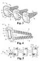
- FIG. 1is a perspective view of an embodiment of a spinal staple in accordance with this invention.
- FIG. 2is a side view of the spinal staple of FIG. 1 .
- FIG. 3is a perspective view of an embodiment of a tether of the present invention including a set of blocks and fasteners with a strand threaded through channels in the blocks.
- FIG. 4is a side view of the embodiment of FIG. 3 .
- FIG. 5is a top view of an alternative to the embodiment of FIG. 3 where the strand is an adjustable spinal tether in a figure eight configuration.
- FIG. 6is a top view of an alternative to the embodiment of FIG. 5 with the tether in a straight loop configuration.
- FIG. 7is a perspective view of another embodiment in which the channels open through the top surface of the blocks.
- FIG. 8Ais a schematic illustration of the embodiment of FIG. 3 attached to vertebral bodies on the convex side of a child's scoliotic spine.
- FIG. 8Bis a schematic illustration of an alternative embodiment of FIG. 8A where the strand is knotted in between the blocks.
- FIG. 9Ais a schematic illustration of the embodiment of FIG. 5 attached to vertebral bodies on the convex side of a spine.
- FIG. 9Bis a schematic illustration of an alternative embodiment of FIG. 9A where the adjustable strand is crimped in between the blocks.
- FIG. 10Ais a cross-sectional view of one embodiment of the interconnection between the fasteners and the blocks.
- FIG. 10Bis a cross-sectional view of another embodiment of the interconnection between the fasteners and the blocks having a screw back-out mechanism.
- FIG. 11is a cross-sectional view of another embodiment of the interconnection between the fasteners and the blocks.
- FIG. 12Ais a schematic illustration of the embodiment of FIG. I attached to vertebral bodies on the convex side of a spine.
- FIG. 12Bis a schematic illustration of the embodiment of FIG. 13 or FIG. 14 attached to vertebral bodies on a convex side of a spine.
- FIG. 12Cis a schematic illustration of the embodiment of FIG. 15 attached to vertebral bodies on the convex side of the spine.
- FIG. 13Ais a side view of another embodiment of a spinal staple.
- FIG. 13Bis a top view of the spinal staple of FIG. 13A
- FIG. 13Cis a side view of FIG. 13 A.
- FIG. 13Dis a side view of the spinal staple of FIG. 13A with the insertion position shown in phantom.
- FIG. 14Ais a side view of another embodiment of a spinal staple.
- FIG. 14Bis a top view of the embodiment of FIG. 14 A.
- FIG. 14Cis a side view of the embodiment of FIG. 14 A.
- FIG. 14Dis a perspective view of the embodiment of the spinal staple of FIG. 14 A.
- FIG. 14Eis a side view of the embodiment of the spinal staple of FIG. 14A showing the tines in the insertion position in phantom.
- FIG. 15Ais a side view of another embodiment of a spinal staple of the present invention.
- FIG. 15Bis a top view of the embodiment of FIG. 15 A.
- FIG. 15Cis another side view of the embodiment of the spinal staple of FIG. 15 A.
- FIG. 15Dis a perspective view of the embodiment of FIG. 15 A.
- FIG. 15Eis a side view of the embodiment of the spinal staple of FIG. 15A showing the times in the insertion position in phantom.
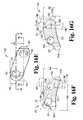
- FIG. 16Ais a side view of another embodiment of a block.
- FIG. 16Bis a top view of the embodiment of the block of FIG. 16 A.
- FIG. 16Cis another side view of the embodiment of the block in FIG. 16 A.
- FIG. 16Dis a perspective view of the embodiment of the block of FIG. 16 A.
- FIG. 16Eis another top view of FIG. 16A illustrating further detail of the embodiment of the block.
- FIG. 16Fis a cross-sectional view along the line 16 F in FIG. 16 E.
- FIG. 16Gis another cross-sectional view of FIG. 16E along the line 16 G.
- FIG. 16His another side view of the embodiment of FIG. 16A illustrating further detail.
- FIG. 16Iis a cross-sectional view of FIG. 16H along the lines 16 I.
- That ideais the correction of spinal deformities, particularly scoliosis, through fusionless tethering.
- the correction of the deformityis achieved by attaching a tether to the vertebral bodies on the convex side of the spine. This tether will minimize or arrest growth on the convex or “long” side of the spine and allow the concave or “short” side of the spine to grow and catch up with the long side.
- fusionless tetheringmay treat abnormal spinal alignment by simply preventing further misalignment such as curve progression.
- a wide variety of surgical approachesmay be used in implementing tethering of the convex side.
- One approachis an open thoracotomy (standard).
- Another surgical approach contemplatedis a minimally invasive thoracoscopic approach (endoscopic).
- the surgical approachmay also be a combined anterior/posterior approach (standard or endoscopic). It should be understood that the invention can be practiced using other surgical approaches known to persons of ordinary skill in the art.
- the tether used to selectively constrain growthwill include at least one longitudinal element and one anchor with an interconnection between the longitudinal element and the anchor.
- the longitudinal element and the anchormay be one and the same.
- the followingdiscusses generally some of the types of apparatus that may be used. Additionally, it should be understood that most, if not all, of the longitudinal elements or anchors may be manufactured from, but are not limited to, conventional implant metals, such as stainless steel or titanium. It should be further understood, and will be discussed in some detail for particular embodiments, that the longitudinal elements and anchors may take advantage of the shape memory and superelastic characteristics of shape memory materials including, for example, a shape memory alloy (“SMA”) such as nickel titanium.
- SMAshape memory alloy
- a list of potential longitudinal elementsincludes, but is not limited to, staples, cables, artificial strands, rods, plates, springs, and combinations of devices from the foregoing list. Details of each individual element will be discussed briefly.
- the longitudinal elementmay be a spinal staple formed in a variety of shapes and sizes depending on its application. Staples may act as either the longitudinal element, the anchor, or both. These staples may be manufactured from conventional implant metal, such as stainless steel or titanium. In one preferred embodiment, however, the staples are manufactured out of shape memory materials or alloys such as nickel titanium to enhance fixation. One example of such an alloy is Nitinol sold by Memry Corporation of Menlo Park, California. Further details of preferred use, size, and material selection for the spinal staple may be found in copending patent application U.S. Ser. No. 09/421,903 entitled “Shape Memory Alloy Spinal Staple” filed on the same day as the present application and commonly assigned to the assignee of the present application, the disclosure of which is incorporated herein by reference.
- the use of artificial or synthetic strandsmay potentially add additional flexibility and motion to this fusionless tethering procedure.
- the artificial strandmay be manufactured from a braided polymer rope.
- the artificial strandwill be an adjustable spinal tether. Details of various embodiments of the adjustable spinal tether may be found in provisional patent application U.S. Ser. No. 60/130,910, entitled “Adjustable Spinal Tether” filed on Apr. 23, 1999 and commonly assigned to the assignee of the present application, the disclosure of which is incorporated herein by reference.
- Such an artificial strandis preferably (but not necessarily) used in conjunction with a block similar or identical to various embodiments of the “Hopf blocks” disclosed in U.S. Pat. No. 5,702,395 to Hopf entitled “Spine Osteosynthesis Instrumentation for an Anterior Approach” the disclosure of which is incorporated herein by reference. It is contemplated as within the scope of the invention, however, that the artificial strand may be utilized for fusionless tethering in a variety of manners. These include, but are not limited to, being attached to or around anchors such as screws and staples. It is further contemplated as within the scope of the invention that the artificial strand may also act as both the longitudinal element and the anchor by being secured directly around the vertebrae to be tethered.
- the longitudinal elementis a flexible rod. These could be manufactured of small diameter and/or flexible material such as a super elastic SMA. In a similar manner plates may be used as a longitudinal element. The plates can be used with or without slots allowing implants to slide. Another possible choice is a spring. Springs have been used historically in spinal instrumentation and could form the longitudinal element. Again, to reiterate, it should be understood that combinations of any or all of the above may be used as a longitudinal element when deemed appropriate.
- staplescan be both anchors as well as longitudinal elements since they possess the characteristics of both. These staples can be either conventional or a SMA as stated above. Also available for use in this capacity are scaled up suture anchor type products. Novel approaches using such products known in the art are available to fix to soft cancellous bone such as that found in a vertebral body. Additionally, screw down fixation plates, posts, etc. as are known to those of ordinary skill in the art, may be used as anchors.
- Another potential anchoris an expandable screw.
- Examplesinclude Mollie bolt type implants that are initially screwed into the vertebral body and expand through some mechanism. It is again possible to take advantage of the properties of shape memory materials to accomplish the expansion mechanism.
- Conventional screws and bone screwsmay also serve as anchors. These screws may be coated with any number of osteoinductive or osteoconductive materials to enhance fixation as desired.
- the selection of the longitudinal elements and anchors from those previously discussed and others known in the artalso leaves possible the selection of a wide variety of interconnections between the two.
- their connection to the longitudinal elementscan be governed by a number of different parameters. They could be constrained or unconstrained connections; the anchor could be allowed to slide along the longitudinal element or articulate with it, as in the case of a ball joint, or even float within some neutral zone. Several scenarios are envisioned.
- the firstis constrained. This would involve constrained interconnection scenarios between all anchors and longitudinal elements.
- the secondis un-constrained. This would involve simple connections in which no significant restrictions exist between the longitudinal element and the anchor.
- An exampleis an artificial strand band around a post, or a screw through an artificial strand ribbon.
- the third scenariois ends constrained with middle elements un-constrained.
- the constructwould possess constrained interconnections between the end anchors and the longitudinal elements with unconstrained interconnections in between. These unconstrained interconnections could be either sliding situations or ball joint situations.
- the fourth scenariois ball joint interconnections. Ball joints represent a semiconstrained situation in which the anchor cannot slide up or down the longitudinal element, but can articulate within some spherical range of motion. It should be understood that combinations of any or all of the above may be used as appropriate in practicing the present invention.
- the above disclosuredeals specifically with the broad range of device concepts envisioned for fusionless tethering of deformities in order to achieve permanent correction.
- the specifics with regard to the methodare similarly broad.
- a wide range of spinal deformitiescould be managed.
- the primary indicationswill be progressive idiopathic scoliosis with or without sagiftal deformity in either infantile or juvenile patients.
- the preferred patient population upon which to practice the present inventionis prepubescent children (before growth spurt) less than ten years old.
- Other patient groups upon which the present invention may be practicedinclude adolescents from 10-12 years old with continued growth potential.
- fusionless tetheringmay be used on older children whose growth spurt is late or who otherwise retain growth potential.
- fusionless tetheringmay also find use in preventing or minimizing curve progression in individuals of various ages.
- tetheringwill take place on the convex side of the curve.
- An anterior, minimally invasive (thoracoscopic) procedurecan be carried out on the convex side of the spinal curve in order to prevent continued growth on that side of the curve.
- the untethered side of the spinewill grow unconstrained, ultimately eliminating the curvature of the spine in the frontal plane. It is preferable to deliver this method of treatment in a minimally invasive approach using thoracoscopic instrumentation. It is contemplated as within the scope of the invention, however, that open use of these systems may be appropriate in some cases.
- the proceduremay be posterior as well as anterior, or some combination of both.
- fusionless correction of scoliosisis achieved by thoracoscopically placing shape memory alloy staples into the vertebral bodies on the convex side of the spine.
- the stapleswill span the intervertebral space and act as a tether on the spine. This tether will arrest growth on the convex (“long”) side of the spine and allow the concave (“short”) side of the spine to grow and catch up with the long side.
- the staplemay then be removed thoracoscopically if desired. The removal of the staples permits further growth of the vertebral bodies. It should be understood that the method described is equally applicable in non-endoscopic procedures. It should be further understood that the staples used may be made of a conventional implant metal such as titanium or stainless steel instead of a SMA.
- contraindications for use of thoracoscopically assisted spinal staplingshould be noted: (1) Inability to wear an orthosis postoperatively, (2) Greater than 40 degree kyphosis, (3) Medical contraindication to general anesthetic, (4) Pulmonary function which would contraindicate intraoperative collapse of the convex lung, and (5) Scoliosis deformity where three or more disc spaces are not accessible to thoracoscopically assisted vertebral interbody stapling. It should be understood, however, that the presence of any or all of the above mentioned contraindications does not preclude the potential utility of spinal stapling and/or vertebral body tethering.
- the general details of one embodiment of the surgical techniquewould be as follows.
- General anesthesiais utilized.
- a double lumen endotracheal tubeis inserted, with possible assistance of fiberoptic visualization.
- the convex lungis collapsed.
- a general or vascular surgeon familiar with endoscopic surgery in the thoraxmay be used as an assistant.
- the patientis positioned in the lateral decubitus position with the convex side of the scoliosis in the up position.
- the tableis not flexed.
- Five vertebrae(four intervertebral discs) are usually stapled.
- the apical vertebral body, the two vertebrae proximal, and the two vertebrae distalare treated.
- Three endoscopic portsare utilized.
- the first portis anterior and positioned over the apex of the scoliosis.
- the second and third portsare made in the posterior auxiliary line with the second port being centered over the second vertebrae of the five being treated and the third port being centered over the fourth vertebrae being treated.
- the endoscopeis maintained in the first port and a fan retractor is placed in the second port.
- An anterior-posterior (AP) radiographis used to confirm the levels. The parietal pleura is not excised and the segmental vessels are avoided.
- the main implantis of course a spinal staple, preferably manufactured from a shape memory material.
- the sizewill vary depending on the size and number of the vertebral bodies to be spanned.
- the instruments used in the proceduremay also include: Staple Awl, Staple Opener, Straight Staple Inserter, Angled Staple Inserter, Staple Impactor, Staple Extractor.
- Pilot holesare made using the Staple Awl.
- the pilot holesare made anterior to the midbody of the vertebrae.
- the Staple Awlis inserted part way and position is checked with either x-ray or image intensifier.
- an electric cauterizer(Bovie) can be placed in contact with the endcap of the Staple Awl to minimize bleeding from the pilot holes.
- two sets of pilot holesare made at each level to accommodate two staples per disc space. Two staples are then placed spanning each disc space. The first staple is loaded into either the Straight Staple Inserter or the Angled Staple Inserter. The staple is then placed into the pilot holes previously made with the Staple Awl.
- the Insertermay be tapped with a mallet to facilitate placement of the staple.
- the stapleis then released from the Inserter and then the instrument is removed.
- the Staple Impactormay be used in conjunction with a mallet for final seating of the staple into the bone.
- the aforementioned stepsare repeated for the next staple at that spinal level. It should be understood, however, that tethering may also be accomplished with just one staple instead of two spanning each disc space. It should be further understood that the use of more than one staple allows for correction of spinal curvature in more than one plane.
- the instruments in the second and third portsare switched and the remaining two discs are stapled.
- the woundsare closed and a ten or twelve gauge chest tube is inserted which is withdrawn at twenty-four hours postop.
- the chest tubeis used to prevent pneumothorax since there is no hemothorax. Once the endoscope is in place, the remainder of the procedure seldom takes more than one hour. Hospitalization is usually for two to three days.
- Apical vertebral interbody staplingtheoretically affords immediate and reversible fixation of the anterior vertebral physes. Thoracoscopic insertion minimizes damage to surrounding tissues and permits placement of multiple staples to allow curve correction in more than one plane.
- Staple 100is generally U-shaped with crossbar 101 between legs 102 and 103 .
- Staple 100has inner surface 110 and outer surface 120 .
- Leg 102has a pointed tip 104 and leg 103 has a pointed tip 105 for insertion into the vertebral bodies. It should be understood that tips 104 , 105 may have a variety of configurations.
- Leg 102has barbs 106 on inner surface 110 and barbs 107 on outer surface 120 .
- leg 103has barbs 108 on inner surface 110 and barbs 109 on outer surface 120 .
- Barbs 106 , 107 , 108 , and 109aid in the prevention of staple backout. Having barbs on both inner surface 110 and outer surface 120 of each leg 102 , 103 of staple 100 allows the use of shorter barbs in the direction transverse to the longitudinal axis of each leg. It should be understood, however, that each leg 102 , 103 may only have barbs on the inner surface 110 or outer surface 120 .
- crossbar 101 , and legs 102 and 103all have a nearly elliptical profile obtained by truncating a circular cross-section.
- a staple design with an elliptical or near elliptical crossbar 101is helpful in controlling rotation of the staple 100 and permits some assistance in staple removal.
- the profile of legs 102 , 103 and crossbar 101may be other than elliptical, such as a circular cross-section.
- legs 102 , 103 and connecting portion 101may have different profiles.
- the staple design of FIGS. 1 and 2may be made of commercially pure titanium, some other conventional implant metal, or even a SMA.
- the staplesare preferably made of nitinol, a biocompatible, shape memory metal alloy of titanium and nickel. Staples are capable of being bent when cooled and reform to their original shape when reheated. It is also possible to take advantage of the shape memory alloy's ability to transform from its austentic state to a stress induced martensitic state. The metal changes shape with temperature or under the influence of stress because of crystalline phase changes. Thus a staple made of a SMA can be inserted in two different ways as desired.
- the SMA stapleis cooled and then deformed while at a temperature less than the transformation temperature at which it is in the martensitic phase.
- the stapleis then inserted in its deformed shape and when heated will reform to its original shape.
- the stapleis deformed and inserted while held in the deformed state.
- the SMAis selected to have a temperature transformation range such that the staple undergoes a transition from austenite to stress-induced martensite under the influence of the deformation forces.
- the metal's properties at the higher temperatureare similar to those of titanium.
- the temperature at which the staples will undergo the shape transformationcan be controlled by the manufacturing process and the selection of the appropriate alloy composition. Damage to the surrounding tissues should be negligible if the transformation temperature is near body temperature. There is no threat of thermal injury to the spinal cord or nerves, or adjacent vascular structures.
- Nitinolhas a very low corrosion rate and has been used in a variety of medical implants (i.e., orthodontic appliances, stents). Implant studies in animals have shown minimal elevations of nickel in the tissues in contact with the metal; the levels of titanium are comparable to the lowest levels found in tissues near titanium hip prostheses.
- Another device useful for correction of spinal deformities through fusionless tetheringinvolves the use of blocks similar or identical to those disclosed in the above mentioned U.S. Pat. No. 5,702,395 to Hopf titled “Spine Osteosynthesis Instrumentation for an Anterior Approach” along with cabling or artificial strands.
- Several preferred embodiments for use as an artificial strandare disclosed in the above mentioned provisional patent application U.S. Ser. No. 60/130,910 entitled “Adjustable Spinal Tether.”
- one embodimentincludes a set of three blocks with corresponding fasteners and a synthetic strand or cable threaded through channels in the blocks is shown. It should be understood that anywhere from two to greater than five blocks may be used. In one preferred embodiment the number of blocks is three.
- Each block 10has a top surface 11 and a bottom surface 12 along with first and second sets of opposing side surfaces. The block 10 is oriented so that in the first set, side surfaces 13 , 14 are located on an anterior and a posterior part respectively of the spine (see also FIGS. 8 and 9 ).
- the block 10has a generally curved shape in a transverse direction from the anterior surface 13 to the posterior surface 14 corresponding to the antero-lateral anatomy of vertebral bodies.
- the bottom surface 12is configured to contact a vertebral body.
- Each block 10has a second set of side surfaces 15 , 16 which are oriented substantially upward and downward along the longitudinal axis S k of the spine (see FIGS. 8 and 9 ).
- the upper surface 15 and lower surface 16 of each block 10define at least one opening or channel for receiving synthetic strand 38 .
- the channelmust either have a post or divider somewhere along its length around which the strand 38 is wrapped or else the strand 38 may be threaded through the channel and around either the top surface 11 or bottom surface 12 of each block 10 .
- each block 10has two substantially parallel channels, an anterior channel 20 and a posterior channel 21 .
- Anterior channel 20 and posterior channel 21extend in a direction along a line connecting upper surface 15 and lower surface 16 . It is contemplated as within the scope of the invention that anterior channel 20 and posterior channel 21 may extend in different directions and/or be curved in between upper surface 15 and lower surface 16 . It is further contemplated as within the scope of the invention that anterior channel 20 and posterior channel 21 may be at an angle with respect to either or both of upper surface 15 and lower surface 16 . Moreover, channels 20 and 21 may both be closer to anterior surface 13 than posterior surface 14 or vice versa. Selection of various channel orientations permits configurations for the synthetic strand other than the figure eight or straight loop configuration discussed below. Also, it should be understood that the channels such as 20 and 21 may instead connect the first set of opposing side surfaces 13 and 14 or may connect some combination of the first and second sets of opposing side surfaces.
- each block 10further defines at least one bore extending between top surface 11 and bottom surface 12 .
- Each block 10may have one or more bores for receiving a fastener to connect each block to a vertebral body.
- block 10has two bores, an anterior bore 22 and a posterior bore 23 . It should be understood that each block 10 may have only one bore or more than two depending on the number of fasteners a surgeon wishes to use to attach each block to a vertebral body.
- Each bore 22 , 23extends between the top surface 11 and bottom surface 12 of block 10 . Bores 22 , 23 are defined in block 10 with dimensions such that each bore may receive one of the fasteners used to attach the block 10 to the vertebral body.
- bores 22 , 23 near bottom surface 12are preferably sized to snugly receive the heads 32 , 33 of fasteners 30 , 31 .
- bore 22has a top portion 22 a and bottom portion 22 b .
- bore 23has a top portion 23 a and a bottom portion 23 b .
- Top portions 22 a and 23 aare preferably (but not necessarily) tapered for facilitating insertion of fasteners 30 , 31 through bores 22 , 23 respectively.
- the head 32 of fastener 30has a top portion 32 a with a notch therein for receiving a driving mechanism and a bottom portion 32 b configured to engage the bottom portion 22 b of bore 22 .
- the head 33 of fastener 31has a top portion 33 a with a notch therein for receiving a driving mechanism and a bottom portion 33 b configured to engage the bottom portion 23 b of bore 23 .
- bore 122has a top portion 122 a and bottom portion 122 b .
- bore 123has a top portion 123 a and a bottom portion 123 b .
- Top portions 122 a and 123 aare preferably (but not necessarily) tapered for facilitating insertion of fasteners 130 , 131 through bores 122 , 123 respectively.
- the head 132 of fastener 130has a top portion 132 a with a notch therein for receiving a driving mechanism and a bottom portion 132 b configured to engage the bottom portion 122 b of bore 122 .
- the head 133 of fastener 131has a top portion 133 a with a notch therein for receiving a driving mechanism and a bottom portion 133 b configured to engage the bottom portion 123 b of bore 123 .
- the head 132 of fastener 130has external threading 132 c defined thereon which engages threading 122 c defined in bore 122 and aids in the prevention of screw back out.
- the head 133 of fastener 131has threading 133 c defined on the head 133 which engages threading 123 c defined in bore 123 .
- bores 22 , 23may also be sized to loosely receive heads 32 and 33 .
- the bottom portion of bores 22 , 23 and heads 32 , 33may both be shaped for ball and socket interconnection allowing the pivoting or swiveling of the connecting portion of fasteners 30 , 31 relative to each block 10 .
- the bottom portions 32 b ′, 33 b ′ of heads 32 , 33are hemispherical as are the bottom portions 22 b ′, 23 b ′.
- the top portions 22 a , 23 aare preferably tapered to facilitate insertion of the fasteners through the bores.
- the bores 22 , 23 and heads 32 , 33may be shaped for engagement such that the angle of the fasteners 30 , 31 with respect to each other and the block 10 is substantially fixed. It should be understood that in either case, it may be desirable in some situations to use a screw back out system as described with reference to FIG. 10B or others known in the art.
- bore 22intersects with channel 20 and bore 23 intersects channel 21 . It should be understood, however, that the bores 22 , 23 need not intersect channels 20 , 21 . In the embodiment where the bores 22 , 23 intersect the channels 20 , 21 , each bore is preferably defined in such a manner that the top of heads 32 , 33 of fasteners 30 , 31 are not within channels 20 , 21 when fasteners 30 , 31 are in the bottom portion of bores 22 , 23 (see FIGS. 5, 8 , and 9 ). As a result, strand or cable 38 is unobstructed when threaded through channels 20 , 21 .
- the artificial strand 38may be a strand with two ends tied or spliced together (see FIGS. 8 A and 8 B).
- the artificial strand 38may be made of any suitable biocompatible material such as stainless steel or titanium or a polymer such as polyester or polyethylene.
- another embodimenthas adjustable spinal tether 40 threaded through the channels 20 , 21 of blocks 10 .
- Adjustable spinal tether 40has a strand or cable portion 39 having a first end 41 and a second end 42 . First end 41 ends in a leader 43 for ease of threading adjustable spinal tether 40 through the channels 20 , 21 in blocks 10 .
- the leader 43may be an extrusion of first end 41 or may be otherwise affixed onto first end 41 by press fitting, adhesive, or other means known in the art. Details of various embodiments of the adjustable spinal tether construction may be found in the above mentioned patent application titled “Adjustable Spinal Tether.”
- Second end 42may be wrapped around or otherwise attached to a grommet 44 .
- the adjustable spinal tethermay have second end 42 looped around on itself to form an eyelet (not shown) without the need for a grommet.
- the leader 43 and first end 41are threaded through grommet 44 and crimp 45 attached to the grommet 44 .
- Crimp 45has external threading 47 matching internal threading (not shown) on lock nut 46 .
- Lock nut 46is tightened down on crimp 45 to secure crimp 45 on strand or cable 39 when the appropriate length is threaded through the channels 20 , 21 of blocks 10 and drawn taut. The excess length of strand 39 may then be trimmed off above crimp 45 .
- the strand 38 , 39may be threaded through blocks 10 in a figure eight configuration.
- the strand 38may also be threaded through blocks 10 in a straight loop configuration.
- the strand 38 or adjustable spinal tether 40may be threaded through the channels in the blocks 10 in either a figure eight or loop configuration or any combination of both as desired.
- blocks 10 ′are shown with like elements labeled as previously.
- Blocks 10 ′have anterior channel 20 ′ and posterior channel 21 ′.
- anterior channel 20 ′ and posterior channel 21 ′extend between upper surface 15 ′ and lower surface 16 ′ as well as up through top surface 11 ′.
- anterior channel 20 ′ and posterior channel 21 ′are defined such that the portion nearer to bottom surface 12 is slightly offset from that defined in top surface 11 ′.
- the channels 20 ′, 21 ′ in blocks 10 ′permit the synthetic strand 38 to be inserted into blocks 10 ′ through top surface 11 ′. Since channels 20 ′, 21 ′ have a slightly offset region nearer to the bottom surface 12 , when synthetic strand 38 is drawn taut it is secured within the channels and will not slip out through top surface 11 ′.
- blocks 10are shown attached to vertebral bodies 60 with artificial strand 38 spanning intervertebral discs 61 .
- the ends of strand 38are shown tied together in a knot 65 .
- knot 65may be tied in an intermediate location between two of the vertebral blocks 11 as opposed to knot 65 as seen in FIG. 8 A.
- blocks 10are again shown attached to vertebral bodies 60 .
- the intervertebral discs 61are spanned by an artificial strand 39 which is part of adjustable spinal tether 40 .
- the crimp 45may be at an intermediate location between blocks.
- FIGS. 8A, 8 B, 9 A, and 9 Bit should be noted that the arrow S k parallels the longitudinal axis of the spinal column made up of vertebral bodies and intervertebral discs.
- FIG. 12Aa plurality of spinal staples 100 with legs 102 , 103 anchored in adjacent vertebral bodies 60 are shown.
- Crossbar 101spans intervertebral disc 61 .
- FIG. 12Ban embodiment is shown wherein two staples 200 are anchored in adjacent vertebral bodies 60 .
- the spinal staples 200have notches 221 on the back of the staple for final seating of the staple into bone. This allows the surgeon to drive in each tine independently as necessary.
- FIG. 12Ca plurality of spinal staples 400 are anchored adjacent vertebral body 60 .
- each spinal staple 400has four prongs.
- the spinal staplesmay include notches on the back of the staple as desired. It should be further understood that any of the embodiments disclosed may entail the use of one, two, or even more than two spinal staples at each level.
- Vertebral interbody staple 200is generally u-shaped with cross bar 201 between legs 202 and 203 .
- Staple 200has inner surface 210 and outer surface 220 .
- Leg 202has a pointed tip 204 and leg 203 has a pointed tip 205 for insertion into the vertebral bodies.
- tips 204 , 205may have a variety of configurations.
- the legs or tines in all of the embodiments in FIGS. 13-15may have barbs on the inner surface or outer surface as desired.
- the back of staple 200has a plurality of notches 221 for final seating of the staple into the bone or vertebrae. Notches 221 aid the surgeon in driving in each tine or leg 202 , 203 independently as necessary (see FIG. 12 B).
- Spinal staple 200has a center line 215 around which it is symmetrical. An angle 225 subtended by axis 215 and a line extending from the tip 205 of leg 203 preferably defines an angle of 37 degrees. Similarly, the angle 226 from between the inner surface 210 and outer surface 220 of leg 202 is preferably 27 degrees.
- the width 230 of the staple 200 between tip 204 and tip 205is preferably 9.5 mm and the greatest width 227 of staple 200 is preferably 19.5 mm.
- the height 232 of the notches 221 as illustratedis on the order of 0.5 mm and similarly the thickness 231 of crossbar 201 and a notch 221 is preferably approximately 2.25 mm.
- the height 229 of spinal staple 200is preferably on the order of 16 mm.
- the distance 233 between adjacent notches 221is approximately 1.5 mm.
- Vertebral interbody staple 300is generally unshaped with cross bar 301 between legs 302 and 303 .
- Staple 300has inner surface 310 and outer surface 320 .
- Leg 302has a pointed tip 304 and leg 303 has a pointed tip 305 for insertion into the vertebral bodies. It should be understood that tips 304 , 305 may have a variety of configurations.
- the back of staple 300has a plurality of notches 321 for final seating of the staple into the bone or vertebrae. Notches 321 aid the surgeon in driving in each tine or leg 302 , 303 independently as necessary.
- Spinal staple 300has a center line 315 around which it is symmetrical. An angle 325 subtended by axis 315 and a line extending from the tip 305 of leg 303 preferably defines an angle of 50 degrees. Similarly, the angle 326 is preferably 50 degrees.
- the width 330 of the staple 300 between tip 304 and tip 305is preferably 9.5 mm and the greatest width 327 of staple 300 is preferably 17.18 mm.
- the height 329 of spinal staple 300is preferably on the order of 10 mm.
- the distance 333 between adjacent notches 321is approximately 2 mm.
- Shape-memory alloy staple 400has four prongs or tines 402 , 404 , 406 , 408 with pointed tips 403 , 405 , 407 , and 409 respectively.
- the legs 402 , 404 , 406 , 408are interconnected by a cross plate 401 .
- the staple 400is symmetrical about the imaginary axis 415 which bisects the width of the staple 400 .
- Crossbar or cross plate 401has a bore 450 defined therein extending between outer surface 420 and inner surface 410 .
- the bore 450is defined by a tapered insertion surface 460 adjoining a surface 461 generally parallel to the axis 415 .
- Bore 450is intended to receive a fastener such as a screw or a bolt. This fastener may be attached to other fasteners received in the bores of other staples by an artificial strand or adjustable tether such as those previously described in the application entitled “Adjustable Spinal Tether.”
- the greatest width 427 of staple 400is on the order of 19.5 mm.
- the lesser width 430 separating pointed tips 403 and 407 or 405 and 409 respectivelyis on the order of 9.5 mm.
- Preferably bore 450has a circular cross section defined by surface 461 having a diameter on the order of 6.5 mm.
- the thickness 431 of crossbar or cross plate 401is on the order of 2.25 mm.
- the width 428 of crossbar or cross plate 401is on the order of 10 mm.
- the height 429 b defined between the pointed tips of the legs of the staple 400 and the arch formed between adjacent legs 402 and 404 or 406 and 408 respectivelyis approximately 12 mm.
- the total height 429 a from the pointed tips to the top most portion of the back of the staple as defined by cross plate 401is approximately 16 mm.
- the height 462 of tapered insertion surface 460 along axis 415 parallel to the axis 415is approximately 1 mm.
- the width 470 of the arch formed between adjacent legs 406 and 408 or 402 and 404 respectivelyis approximately 6 mm.
- the angles 426 subtended by each tip 403 , 405 , 407 , and 409 between inner surface 410 and outer surface 420is approximately 27 degrees.
- the angle 425 subtended between axis 415 and a line tangential to the outer surface 420 at any of the tipsis approximately 37 degrees.
- the deformed martensitic insertion shape of the legs of the staplesis shown in phantom. It should be understood that this deformed state may arise from the formation of martensite because of temperature conditions or the formation of stress induced martensite from the application of a force. After the various embodiments of the staples are inserted in their open position, either the stress is released or the staple is heated to reform the staple to its closed memorized shape.
- Each block 510has a top surface 511 , a bottom surface 512 , intermediate surfaces 551 , 552 , and first and second sets of opposing side surfaces.
- the block 510is oriented so that the first set of side surfaces 513 a , 513 b , and 514 a , 514 b are located on an anterior and a posterior part respectively of the spine (similar to side surfaces 13 and 14 in FIGS. 8 and 9 ).
- the first set of side surfacesincludes an upper anterior side surface 513 a and a lower anterior side surface 513 b and an upper posterior side surface 514 a and lower posterior side surface 514 b .
- the block 510has a generally curved shape in a transverse direction from the lower anterior surface 513 b to the lower posterior surface 514 b corresponding to the antero-lateral anatomy of vertebral bodies.
- the bottom surface 512is preferably (but not necessarily) configured to contact the vertebral body.
- Each block 510has a second set of side surfaces 515 , 516 which are oriented to face substantially upward and downward along the longitudinal axis of the spine, similar to side surfaces 15 , 16 in FIGS. 8 and 9.
- the upper surface 515 and lower surface 516 of each block 510define at least one opening or channel for receiving a synthetic strand or adjustable spinal tether.
- the channelmust either have a post or divider somewhere along its length around which the strand or adjustable spinal tether is wrapped or, alternatively, the strand or adjustable spinal tether may be threaded through the channel and around either the top surface 511 or bottom surface 512 of each block 510 .
- each block 510has two substantially parallel channels, an anterior channel 520 and a posterior channel 521 .
- Anterior channel 520 and posterior channel 521extend in a direction along a line connecting upper surface 515 and lower surface 516 . It is contemplated as within the scope of the invention that anterior channel 520 and posterior channel 521 may extend in different directions and/or be curved in between upper surface 515 and lower surface 516 . It is further contemplated as within the scope of the invention that anterior channel 520 and posterior channel 521 may be at an angle with respect to either or both of upper surface 515 and lower surface 516 . Moreover, channels 520 and 521 may both be closer to anterior surface 513 than posterior surface 514 or vice versa.
- channels such as 520 and 521may instead connect the first set of opposing upper side surfaces 513 a and 514 a or may connect some combination of the first and second sets of opposing side surfaces.
- each block 510further defines at least one bore extending between top surface 511 and bottom surface 512 .
- Each block 510may have one or more bores for receiving a fastener or connect each block to a vertebral body.
- block 510has two bores, an anterior bore 522 and a posterior bore 523 . It should be understood that each block 510 may have only one bore or more than two depending on the number of fasteners a surgeon wishes to use to attach each block to a vertebral body.
- Each bore 522 , 523extends between the top surface 511 and bottom surface 512 of block 510 . Bores 522 , 523 are defined in block 510 with dimensions such that each bore may receive one of the fasteners used to attach the block 510 to the vertebral body.
- the bores of this embodiment of the anterior blockmay include features similar to those described in the previous embodiment and shown in FIGS. 10 and 11.
- the boresmay have tapered surfaces for facilitating insertion of fasteners, may be shaped for a ball and socket interconnection, may have matching threading on the head of a fastener to prevent screw back out and the bores may be arranged in a variety of angles with respect to each other.
- length 539is 15 mm
- length 540is 7.5 mm
- length 541is 15 mm
- length 542is 10.5 mm
- 543is 4.5 mm
- length 544is 10.6 mm
- length 545which defines the diameter of bore 523 at one point is 6.4 mm
- length 546is 20
- length 547which defines the diameter of the bore at one point
- length 548which defines the minimum diameter of the bore is 5.05 mm
- angle 549is five degrees.
- length 560is 8.4 mm
- length 563is 7 mm
- angle 564is 15 degrees and angle 565 is 10 degrees.
- length 570is 3.1 mm
- length 571is 7 mm
- length 572is 12 mm
- angle 573is 10 degrees.
- length 574is 4.53 mm
- length 575is 1 mm
- length 576is 16.85 mm
- length 577is 11.35 mm
- length 578is 7.5 mm
- length 579is 3.53 mm
- length 580is 2 mm
- length 581is 11.85 mm
- length 582is 17.35 mm
- angles 583 and 584are both 20 degrees.
- this embodiment of a blockmay be used in various manners similar or identical to those shown in FIGS. 3-9 with an artificial strand or adjustable tether.
- the advantages of this embodimentinclude the reduction in the amount of volume and the amount of metal. By essentially removing portions of what was a previously rectangular cross section, this embodiment of the block has a lower profile and is less bulky.
Landscapes
- Health & Medical Sciences (AREA)
- Orthopedic Medicine & Surgery (AREA)
- Life Sciences & Earth Sciences (AREA)
- Engineering & Computer Science (AREA)
- Biomedical Technology (AREA)
- Neurology (AREA)
- Surgery (AREA)
- General Health & Medical Sciences (AREA)
- Veterinary Medicine (AREA)
- Heart & Thoracic Surgery (AREA)
- Public Health (AREA)
- Animal Behavior & Ethology (AREA)
- Molecular Biology (AREA)
- Medical Informatics (AREA)
- Nuclear Medicine, Radiotherapy & Molecular Imaging (AREA)
- Rheumatology (AREA)
- Cardiology (AREA)
- Oral & Maxillofacial Surgery (AREA)
- Transplantation (AREA)
- Vascular Medicine (AREA)
- Prostheses (AREA)
- Surgical Instruments (AREA)
Abstract
Description
This application claims the benefit of U.S. Provisional Application No. 60/130,909, filed Apr. 23, 1999.
Current operative methods for treating spinal deformities, particularly scoliosis, include correction of the curve by some internal fixation device, and fusion of the spine in the corrected state usually accomplished by the placement of bone graft between vertebrae. This is usually accomplished with posterior surgery, although anterior procedures are becoming more popular, as well as combinations of anterior and posterior procedures. Several instrumentation systems are available from various manufacturers to correct and stabilize the spine while fusion occurs. Among them are TSRH®, CD™, CD Hopf™, CD Horizon™, ISOLA™, Moss Miami and Synthes Universal Spine Systems. Nonoperative methods do exist and are used when applicable. These nonoperative methods include bracing and observation.
Juvenile idiopathic scoliosis occurs between the ages of 4 and 10 years. It can resolve spontaneously, respond to nonoperative therapy, or progress until fusion is required. Stapling across long bone physes has long been recognized as a predictable method of treating limb malalignment. Vertebral interbody stapling across the cartilaginous endplates and discs was attempted by Nachlas and Borden in a canine scoliosis model. Early human results in the 1950s were disappointing. Roaf reported limited successful correction of scoliosis by uninstrumented convex hemiepiphysiodesis. His study did not have a uniform patient population by skeletal maturity or scoliosis etiology.
Further shortcomings of current operative methods and devices are numerous. Patients with juvenile scoliosis who undergo curve stabilization with subcutaneous rods would be subject to multiple surgical procedures for lengthening as they grow. Anterior and/or posterior spinal fusion in the skeletally immature patient often results in loss of vertebral body height and girth. Additionally, poor self-image may occur in adolescent patients who are braced for scoliosis. Moreover, curve stabilization with bracing is only successful in approximately 75% of patients. Another problem is that some children, while not currently candidates for a definitive fusion procedure, are likely to need such a procedure in the future. These would include children less than ten years of age, small in stature, premenstrual or riser two or lower, and those not physically able to tolerate the surgery required for a definitive fusion procedure. It would be preferable to eliminate the need for that procedure altogether.
Described briefly, one embodiment of the invention is a fusionless method of treating abnormal alignment of a spine of a child or a young adult. The spine has a convex side and a concave side. The method comprises the steps of attaching a tether to at least two vertebral bodies of the spine and then constraining curve progression in a portion of the convex side of the spine.
Another embodiment of the invention is a fusionless method of correcting deformities in a spine of a child or a young adult. The spine has a convex side and a concave side. The method comprises the steps of attaching a tether to at least two vertebral bodies of the spine and selectively constraining growth of the convex side of the spine.
Another embodiment of the invention is a device for restraining growth in a spine having a convex side and a concave side. The device comprises a strand, at least two blocks and a plurality of fasteners. Each block has a top surface, bottom surface and a first and second set of opposing side surfaces. The block is oriented on the spine so that the first set of side surfaces are located on an anterior part and a posterior part respectively of the spine. The block has a generally curved shape in a transverse direction from the anterior part to the posterior part corresponding to the antero-lateral anatomy of vertebral bodies. The bottom surface of the block is configured to contact a vertebral body. At least one fastener connects each block to at least one vertebra on the convex side of the spine. Each block has at least one channel for receiving the strand. Each block also has at least one bore extending between the top and bottom surfaces of the block. The bore receives one of the fasteners which connect the block to a vertebral body.
FIG. 1 is a perspective view of an embodiment of a spinal staple in accordance with this invention.
FIG. 2 is a side view of the spinal staple of FIG.1.
FIG. 3 is a perspective view of an embodiment of a tether of the present invention including a set of blocks and fasteners with a strand threaded through channels in the blocks.
FIG. 4 is a side view of the embodiment of FIG.3.
FIG. 5 is a top view of an alternative to the embodiment of FIG. 3 where the strand is an adjustable spinal tether in a figure eight configuration.
FIG. 6 is a top view of an alternative to the embodiment of FIG. 5 with the tether in a straight loop configuration.
FIG. 7 is a perspective view of another embodiment in which the channels open through the top surface of the blocks.
FIG. 8A is a schematic illustration of the embodiment of FIG. 3 attached to vertebral bodies on the convex side of a child's scoliotic spine.
FIG. 8B is a schematic illustration of an alternative embodiment of FIG. 8A where the strand is knotted in between the blocks.
FIG. 9A is a schematic illustration of the embodiment of FIG. 5 attached to vertebral bodies on the convex side of a spine. FIG. 9B is a schematic illustration of an alternative embodiment of FIG. 9A where the adjustable strand is crimped in between the blocks.
FIG. 10A is a cross-sectional view of one embodiment of the interconnection between the fasteners and the blocks.
FIG. 10B is a cross-sectional view of another embodiment of the interconnection between the fasteners and the blocks having a screw back-out mechanism.
FIG. 11 is a cross-sectional view of another embodiment of the interconnection between the fasteners and the blocks.
FIG. 12A is a schematic illustration of the embodiment of FIG. I attached to vertebral bodies on the convex side of a spine.
FIG. 12B is a schematic illustration of the embodiment of FIG. 13 or FIG. 14 attached to vertebral bodies on a convex side of a spine.
FIG. 12C is a schematic illustration of the embodiment of FIG. 15 attached to vertebral bodies on the convex side of the spine.
FIG. 13A is a side view of another embodiment of a spinal staple.
FIG. 13B is a top view of the spinal staple of FIG. 13A
FIG. 13C is a side view of FIG.13A.
FIG. 13D is a side view of the spinal staple of FIG. 13A with the insertion position shown in phantom.
FIG. 14A is a side view of another embodiment of a spinal staple.
FIG. 14B is a top view of the embodiment of FIG.14A.
FIG. 14C is a side view of the embodiment of FIG.14A.
FIG. 14D is a perspective view of the embodiment of the spinal staple of FIG.14A.
FIG. 14E is a side view of the embodiment of the spinal staple of FIG. 14A showing the tines in the insertion position in phantom.
FIG. 15A is a side view of another embodiment of a spinal staple of the present invention.
FIG. 15B is a top view of the embodiment of FIG.15A.
FIG. 15C is another side view of the embodiment of the spinal staple of FIG.15A.
FIG. 15D is a perspective view of the embodiment of FIG.15A.
FIG. 15E is a side view of the embodiment of the spinal staple of FIG. 15A showing the times in the insertion position in phantom.
FIG. 16A is a side view of another embodiment of a block.
FIG. 16B is a top view of the embodiment of the block of FIG.16A.
FIG. 16C is another side view of the embodiment of the block in FIG.16A.
FIG. 16D is a perspective view of the embodiment of the block of FIG.16A.
FIG. 16E is another top view of FIG. 16A illustrating further detail of the embodiment of the block.
FIG. 16F is a cross-sectional view along theline 16F in FIG.16E.
FIG. 16G is another cross-sectional view of FIG. 16E along theline 16G.
FIG. 16H is another side view of the embodiment of FIG. 16A illustrating further detail.
FIG. 16I is a cross-sectional view of FIG. 16H along the lines16I.
For the purposes of promoting an understanding of the principles of the invention, reference will now be made to the embodiment illustrated in the drawings and specific language will be used to describe the same. It will nevertheless be understood that no limitation of the scope of the invention is thereby intended, such alterations and further modifications in the illustrated device, and such further applications of the principles of the invention as illustrated therein being contemplated as would normally occur to one skilled in the art to which the invention relates.
Various devices and surgical approaches are possible to implement the underlying idea of this invention. That idea is the correction of spinal deformities, particularly scoliosis, through fusionless tethering. The correction of the deformity is achieved by attaching a tether to the vertebral bodies on the convex side of the spine. This tether will minimize or arrest growth on the convex or “long” side of the spine and allow the concave or “short” side of the spine to grow and catch up with the long side. Alternatively, fusionless tethering may treat abnormal spinal alignment by simply preventing further misalignment such as curve progression.
A wide variety of surgical approaches may be used in implementing tethering of the convex side. One approach is an open thoracotomy (standard). Another surgical approach contemplated is a minimally invasive thoracoscopic approach (endoscopic). The surgical approach may also be a combined anterior/posterior approach (standard or endoscopic). It should be understood that the invention can be practiced using other surgical approaches known to persons of ordinary skill in the art.
In any surgical approach used in practicing the invention, the tether used to selectively constrain growth will include at least one longitudinal element and one anchor with an interconnection between the longitudinal element and the anchor. In some cases the longitudinal element and the anchor may be one and the same. The following discusses generally some of the types of apparatus that may be used. Additionally, it should be understood that most, if not all, of the longitudinal elements or anchors may be manufactured from, but are not limited to, conventional implant metals, such as stainless steel or titanium. It should be further understood, and will be discussed in some detail for particular embodiments, that the longitudinal elements and anchors may take advantage of the shape memory and superelastic characteristics of shape memory materials including, for example, a shape memory alloy (“SMA”) such as nickel titanium.
Several devices are contemplated for spanning the longitudinal aspect of the spine during the fusionless tethering procedure. A list of potential longitudinal elements includes, but is not limited to, staples, cables, artificial strands, rods, plates, springs, and combinations of devices from the foregoing list. Details of each individual element will be discussed briefly.
The longitudinal element may be a spinal staple formed in a variety of shapes and sizes depending on its application. Staples may act as either the longitudinal element, the anchor, or both. These staples may be manufactured from conventional implant metal, such as stainless steel or titanium. In one preferred embodiment, however, the staples are manufactured out of shape memory materials or alloys such as nickel titanium to enhance fixation. One example of such an alloy is Nitinol sold by Memry Corporation of Menlo Park, California. Further details of preferred use, size, and material selection for the spinal staple may be found in copending patent application U.S. Ser. No. 09/421,903 entitled “Shape Memory Alloy Spinal Staple” filed on the same day as the present application and commonly assigned to the assignee of the present application, the disclosure of which is incorporated herein by reference.
Another possible selection for the longitudinal element is cabling. Historical spinal instrumentation involved the use of cables (Dwyer) as a fixation method for spinal fusion. However, this use of cable never contemplated that a flexible cable could represent the longitudinal element in a fusionless tethering procedure.
The use of artificial or synthetic strands, much in the same way cable could be used, may potentially add additional flexibility and motion to this fusionless tethering procedure. In one preferred embodiment the artificial strand may be manufactured from a braided polymer rope. In another preferred embodiment the artificial strand will be an adjustable spinal tether. Details of various embodiments of the adjustable spinal tether may be found in provisional patent application U.S. Ser. No. 60/130,910, entitled “Adjustable Spinal Tether” filed on Apr. 23, 1999 and commonly assigned to the assignee of the present application, the disclosure of which is incorporated herein by reference. Such an artificial strand is preferably (but not necessarily) used in conjunction with a block similar or identical to various embodiments of the “Hopf blocks” disclosed in U.S. Pat. No. 5,702,395 to Hopf entitled “Spine Osteosynthesis Instrumentation for an Anterior Approach” the disclosure of which is incorporated herein by reference. It is contemplated as within the scope of the invention, however, that the artificial strand may be utilized for fusionless tethering in a variety of manners. These include, but are not limited to, being attached to or around anchors such as screws and staples. It is further contemplated as within the scope of the invention that the artificial strand may also act as both the longitudinal element and the anchor by being secured directly around the vertebrae to be tethered.
Another possible selection for the longitudinal element is a flexible rod. These could be manufactured of small diameter and/or flexible material such as a super elastic SMA. In a similar manner plates may be used as a longitudinal element. The plates can be used with or without slots allowing implants to slide. Another possible choice is a spring. Springs have been used historically in spinal instrumentation and could form the longitudinal element. Again, to reiterate, it should be understood that combinations of any or all of the above may be used as a longitudinal element when deemed appropriate.
Most of the longitudinal elements discussed above, the staples and artificial strands being possible exceptions, will need to be anchored to the vertebral bodies in order to effectively tether them. Several different anchors are contemplated.
As previously mentioned, staples can be both anchors as well as longitudinal elements since they possess the characteristics of both. These staples can be either conventional or a SMA as stated above. Also available for use in this capacity are scaled up suture anchor type products. Novel approaches using such products known in the art are available to fix to soft cancellous bone such as that found in a vertebral body. Additionally, screw down fixation plates, posts, etc. as are known to those of ordinary skill in the art, may be used as anchors.
Another potential anchor is an expandable screw. Examples include Mollie bolt type implants that are initially screwed into the vertebral body and expand through some mechanism. It is again possible to take advantage of the properties of shape memory materials to accomplish the expansion mechanism. Conventional screws and bone screws may also serve as anchors. These screws may be coated with any number of osteoinductive or osteoconductive materials to enhance fixation as desired.
The selection of the longitudinal elements and anchors from those previously discussed and others known in the art also leaves possible the selection of a wide variety of interconnections between the two. Once the anchors are in place, their connection to the longitudinal elements can be governed by a number of different parameters. They could be constrained or unconstrained connections; the anchor could be allowed to slide along the longitudinal element or articulate with it, as in the case of a ball joint, or even float within some neutral zone. Several scenarios are envisioned.
The first is constrained. This would involve constrained interconnection scenarios between all anchors and longitudinal elements. The second is un-constrained. This would involve simple connections in which no significant restrictions exist between the longitudinal element and the anchor. An example is an artificial strand band around a post, or a screw through an artificial strand ribbon.
The third scenario is ends constrained with middle elements un-constrained. In this case the construct would possess constrained interconnections between the end anchors and the longitudinal elements with unconstrained interconnections in between. These unconstrained interconnections could be either sliding situations or ball joint situations. The fourth scenario is ball joint interconnections. Ball joints represent a semiconstrained situation in which the anchor cannot slide up or down the longitudinal element, but can articulate within some spherical range of motion. It should be understood that combinations of any or all of the above may be used as appropriate in practicing the present invention.
The above disclosure deals specifically with the broad range of device concepts envisioned for fusionless tethering of deformities in order to achieve permanent correction. The specifics with regard to the method are similarly broad. A wide range of spinal deformities could be managed. The primary indications will be progressive idiopathic scoliosis with or without sagiftal deformity in either infantile or juvenile patients. The preferred patient population upon which to practice the present invention is prepubescent children (before growth spurt) less than ten years old. Other patient groups upon which the present invention may be practiced include adolescents from 10-12 years old with continued growth potential. It should be understood that fusionless tethering may be used on older children whose growth spurt is late or who otherwise retain growth potential. It should be further understood that fusionless tethering may also find use in preventing or minimizing curve progression in individuals of various ages.
Generally, in the case of scoliosis, tethering will take place on the convex side of the curve. An anterior, minimally invasive (thoracoscopic) procedure can be carried out on the convex side of the spinal curve in order to prevent continued growth on that side of the curve. As the pre-growth spurt child approaches puberty, the untethered side of the spine will grow unconstrained, ultimately eliminating the curvature of the spine in the frontal plane. It is preferable to deliver this method of treatment in a minimally invasive approach using thoracoscopic instrumentation. It is contemplated as within the scope of the invention, however, that open use of these systems may be appropriate in some cases. It is further contemplated as within the scope of the invention that the procedure may be posterior as well as anterior, or some combination of both. Finally, it should be understood that if the procedure fails to correct the curve but does, in fact, prevent further progression (which includes increase in the magnitude of the curve) it can and should be considered successful.
In one embodiment of the invention, fusionless correction of scoliosis is achieved by thoracoscopically placing shape memory alloy staples into the vertebral bodies on the convex side of the spine. The staples will span the intervertebral space and act as a tether on the spine. This tether will arrest growth on the convex (“long”) side of the spine and allow the concave (“short”) side of the spine to grow and catch up with the long side. Once correction is achieved, the staple may then be removed thoracoscopically if desired. The removal of the staples permits further growth of the vertebral bodies. It should be understood that the method described is equally applicable in non-endoscopic procedures. It should be further understood that the staples used may be made of a conventional implant metal such as titanium or stainless steel instead of a SMA.
The following contraindications for use of thoracoscopically assisted spinal stapling should be noted: (1) Inability to wear an orthosis postoperatively, (2) Greater than 40 degree kyphosis, (3) Medical contraindication to general anesthetic, (4) Pulmonary function which would contraindicate intraoperative collapse of the convex lung, and (5) Scoliosis deformity where three or more disc spaces are not accessible to thoracoscopically assisted vertebral interbody stapling. It should be understood, however, that the presence of any or all of the above mentioned contraindications does not preclude the potential utility of spinal stapling and/or vertebral body tethering.
The general details of one embodiment of the surgical technique would be as follows. General anesthesia is utilized. A double lumen endotracheal tube is inserted, with possible assistance of fiberoptic visualization. The convex lung is collapsed. A general or vascular surgeon familiar with endoscopic surgery in the thorax may be used as an assistant. The patient is positioned in the lateral decubitus position with the convex side of the scoliosis in the up position. The table is not flexed. Five vertebrae (four intervertebral discs) are usually stapled. The apical vertebral body, the two vertebrae proximal, and the two vertebrae distal are treated. Three endoscopic ports are utilized. The first port is anterior and positioned over the apex of the scoliosis. The second and third ports are made in the posterior auxiliary line with the second port being centered over the second vertebrae of the five being treated and the third port being centered over the fourth vertebrae being treated. The endoscope is maintained in the first port and a fan retractor is placed in the second port. An anterior-posterior (AP) radiograph is used to confirm the levels. The parietal pleura is not excised and the segmental vessels are avoided.
A number of general surgical instruments are used in the procedure along with the following system specific implants and instruments. The main implant is of course a spinal staple, preferably manufactured from a shape memory material. The size will vary depending on the size and number of the vertebral bodies to be spanned. The instruments used in the procedure may also include: Staple Awl, Staple Opener, Straight Staple Inserter, Angled Staple Inserter, Staple Impactor, Staple Extractor.
Pilot holes are made using the Staple Awl. The pilot holes are made anterior to the midbody of the vertebrae. The Staple Awl is inserted part way and position is checked with either x-ray or image intensifier. Prior to removal of the Staple Awl from the pilot holes, an electric cauterizer (Bovie) can be placed in contact with the endcap of the Staple Awl to minimize bleeding from the pilot holes. In one preferred embodiment, two sets of pilot holes are made at each level to accommodate two staples per disc space. Two staples are then placed spanning each disc space. The first staple is loaded into either the Straight Staple Inserter or the Angled Staple Inserter. The staple is then placed into the pilot holes previously made with the Staple Awl. The Inserter may be tapped with a mallet to facilitate placement of the staple. The staple is then released from the Inserter and then the instrument is removed. If further seating of the staple is required, the Staple Impactor may be used in conjunction with a mallet for final seating of the staple into the bone. The aforementioned steps are repeated for the next staple at that spinal level. It should be understood, however, that tethering may also be accomplished with just one staple instead of two spanning each disc space. It should be further understood that the use of more than one staple allows for correction of spinal curvature in more than one plane.
The instruments in the second and third ports are switched and the remaining two discs are stapled. The wounds are closed and a ten or twelve gauge chest tube is inserted which is withdrawn at twenty-four hours postop. The chest tube is used to prevent pneumothorax since there is no hemothorax. Once the endoscope is in place, the remainder of the procedure seldom takes more than one hour. Hospitalization is usually for two to three days.
Apical vertebral interbody stapling theoretically affords immediate and reversible fixation of the anterior vertebral physes. Thoracoscopic insertion minimizes damage to surrounding tissues and permits placement of multiple staples to allow curve correction in more than one plane.
With reference to FIGS. 1 and 2, one embodiment of anvertebral interbody staple 100 that may be used in the above described method is shown.Staple 100 is generally U-shaped withcrossbar 101 betweenlegs Staple 100 hasinner surface 110 andouter surface 120.Leg 102 has a pointedtip 104 andleg 103 has a pointedtip 105 for insertion into the vertebral bodies. It should be understood thattips Leg 102 hasbarbs 106 oninner surface 110 andbarbs 107 onouter surface 120. Similarly,leg 103 hasbarbs 108 oninner surface 110 andbarbs 109 onouter surface 120.Barbs inner surface 110 andouter surface 120 of eachleg staple 100 allows the use of shorter barbs in the direction transverse to the longitudinal axis of each leg. It should be understood, however, that eachleg inner surface 110 orouter surface 120.
It should be noted that in onepreferred embodiment crossbar 101, andlegs elliptical crossbar 101 is helpful in controlling rotation of thestaple 100 and permits some assistance in staple removal. It should be understood that the profile oflegs crossbar 101 may be other than elliptical, such as a circular cross-section. It should be further understood thatlegs portion 101 may have different profiles. The staple design of FIGS. 1 and 2 may be made of commercially pure titanium, some other conventional implant metal, or even a SMA.
While details of several embodiments of the staple are discussed in the copending application titled “Shape Memory Alloy Spinal Staple,” some general points are reviewed here for convenience. The staples are preferably made of nitinol, a biocompatible, shape memory metal alloy of titanium and nickel. Staples are capable of being bent when cooled and reform to their original shape when reheated. It is also possible to take advantage of the shape memory alloy's ability to transform from its austentic state to a stress induced martensitic state. The metal changes shape with temperature or under the influence of stress because of crystalline phase changes. Thus a staple made of a SMA can be inserted in two different ways as desired. In one embodiment the SMA staple is cooled and then deformed while at a temperature less than the transformation temperature at which it is in the martensitic phase. The staple is then inserted in its deformed shape and when heated will reform to its original shape. In a second embodiment the staple is deformed and inserted while held in the deformed state. In the second embodiment the SMA is selected to have a temperature transformation range such that the staple undergoes a transition from austenite to stress-induced martensite under the influence of the deformation forces. Thus, when the staple of the second embodiment is inserted and released it is already at a temperature such that it automatically attempts to reform to its original shape.
The metal's properties at the higher temperature (austenite phase) are similar to those of titanium. The temperature at which the staples will undergo the shape transformation can be controlled by the manufacturing process and the selection of the appropriate alloy composition. Injury to the surrounding tissues should be negligible if the transformation temperature is near body temperature. There is no threat of thermal injury to the spinal cord or nerves, or adjacent vascular structures. Nitinol has a very low corrosion rate and has been used in a variety of medical implants (i.e., orthodontic appliances, stents). Implant studies in animals have shown minimal elevations of nickel in the tissues in contact with the metal; the levels of titanium are comparable to the lowest levels found in tissues near titanium hip prostheses.
Another device useful for correction of spinal deformities through fusionless tethering involves the use of blocks similar or identical to those disclosed in the above mentioned U.S. Pat. No. 5,702,395 to Hopf titled “Spine Osteosynthesis Instrumentation for an Anterior Approach” along with cabling or artificial strands. Several preferred embodiments for use as an artificial strand are disclosed in the above mentioned provisional patent application U.S. Ser. No. 60/130,910 entitled “Adjustable Spinal Tether.”
With reference to FIGS. 3 and 4, one embodiment includes a set of three blocks with corresponding fasteners and a synthetic strand or cable threaded through channels in the blocks is shown. It should be understood that anywhere from two to greater than five blocks may be used. In one preferred embodiment the number of blocks is three. Eachblock 10 has atop surface 11 and abottom surface 12 along with first and second sets of opposing side surfaces. Theblock 10 is oriented so that in the first set, side surfaces13,14 are located on an anterior and a posterior part respectively of the spine (see also FIGS.8 and9). Theblock 10 has a generally curved shape in a transverse direction from theanterior surface 13 to theposterior surface 14 corresponding to the antero-lateral anatomy of vertebral bodies. Thebottom surface 12 is configured to contact a vertebral body.
Eachblock 10 has a second set of side surfaces15,16 which are oriented substantially upward and downward along the longitudinal axis Skof the spine (see FIGS.8 and9). Theupper surface 15 andlower surface 16 of eachblock 10 define at least one opening or channel for receivingsynthetic strand 38. In an embodiment with only one channel, the channel must either have a post or divider somewhere along its length around which thestrand 38 is wrapped or else thestrand 38 may be threaded through the channel and around either thetop surface 11 orbottom surface 12 of eachblock 10. In one preferred embodiment (see FIG.3), eachblock 10 has two substantially parallel channels, ananterior channel 20 and aposterior channel 21.Anterior channel 20 andposterior channel 21 extend in a direction along a line connectingupper surface 15 andlower surface 16. It is contemplated as within the scope of the invention thatanterior channel 20 andposterior channel 21 may extend in different directions and/or be curved in betweenupper surface 15 andlower surface 16. It is further contemplated as within the scope of the invention thatanterior channel 20 andposterior channel 21 may be at an angle with respect to either or both ofupper surface 15 andlower surface 16. Moreover,channels anterior surface 13 thanposterior surface 14 or vice versa. Selection of various channel orientations permits configurations for the synthetic strand other than the figure eight or straight loop configuration discussed below. Also, it should be understood that the channels such as20 and21 may instead connect the first set of opposing side surfaces13 and14 or may connect some combination of the first and second sets of opposing side surfaces.
Additionally, eachblock 10 further defines at least one bore extending betweentop surface 11 andbottom surface 12. Eachblock 10 may have one or more bores for receiving a fastener to connect each block to a vertebral body. In onepreferred embodiment block 10 has two bores, ananterior bore 22 and aposterior bore 23. It should be understood that eachblock 10 may have only one bore or more than two depending on the number of fasteners a surgeon wishes to use to attach each block to a vertebral body. Each bore22,23 extends between thetop surface 11 andbottom surface 12 ofblock 10.Bores block 10 with dimensions such that each bore may receive one of the fasteners used to attach theblock 10 to the vertebral body.
The bottom portion ofbores bottom surface 12 are preferably sized to snugly receive theheads fasteners top portion 22aandbottom portion 22b. Similarly bore23 has atop portion 23aand abottom portion 23b.Top portions fasteners bores head 32 offastener 30 has atop portion 32awith a notch therein for receiving a driving mechanism and abottom portion 32bconfigured to engage thebottom portion 22bofbore 22. Similarly, thehead 33 offastener 31 has atop portion 33awith a notch therein for receiving a driving mechanism and abottom portion 33bconfigured to engage thebottom portion 23bofbore 23.
With reference to FIG. 10B, an alternative embodiment is shown with a mechanism to aid in the prevention of screw back out. With reference to FIG. 10B, in which like elements are labeled as previously, it is seen that bore122 has atop portion 122aandbottom portion 122b. Similarly, bore123 has atop portion 123aand abottom portion 123b.Top portions fasteners bores head 132 offastener 130 has atop portion 132awith a notch therein for receiving a driving mechanism and abottom portion 132bconfigured to engage thebottom portion 122bofbore 122. Similarly, thehead 133 offastener 131 has atop portion 133awith a notch therein for receiving a driving mechanism and abottom portion 133bconfigured to engage thebottom portion 123bofbore 123. Thehead 132 offastener 130 hasexternal threading 132cdefined thereon which engages threading122cdefined inbore 122 and aids in the prevention of screw back out. Similarly, thehead 133 offastener 131 has threading133cdefined on thehead 133 which engages threading123cdefined inbore 123.
It should be understood that bores22,23 may also be sized to loosely receiveheads bores fasteners block 10. With reference to FIG. 11 in which like elements are labeled as previously, thebottom portions 32b′,33b′ ofheads bottom portions 22b′,23b′. Again thetop portions bores fasteners block 10 is substantially fixed. It should be understood that in either case, it may be desirable in some situations to use a screw back out system as described with reference to FIG. 10B or others known in the art.
In one embodiment, bore22 intersects withchannel 20 and bore23 intersectschannel 21. It should be understood, however, that thebores channels bores channels heads fasteners channels fasteners bores 22,23 (see FIGS. 5,8, and9). As a result, strand orcable 38 is unobstructed when threaded throughchannels
With reference to FIG. 3, theartificial strand 38 may be a strand with two ends tied or spliced together (see FIGS.8A and8B). Theartificial strand 38 may be made of any suitable biocompatible material such as stainless steel or titanium or a polymer such as polyester or polyethylene. With reference to FIG. 5, another embodiment has adjustablespinal tether 40 threaded through thechannels blocks 10. Adjustablespinal tether 40 has a strand orcable portion 39 having afirst end 41 and asecond end 42. First end41 ends in aleader 43 for ease of threading adjustablespinal tether 40 through thechannels blocks 10. Theleader 43 may be an extrusion offirst end 41 or may be otherwise affixed ontofirst end 41 by press fitting, adhesive, or other means known in the art. Details of various embodiments of the adjustable spinal tether construction may be found in the above mentioned patent application titled “Adjustable Spinal Tether.”
With reference to FIG. 7, in yet another embodiment blocks10′ are shown with like elements labeled as previously.Blocks 10′ haveanterior channel 20′ andposterior channel 21′. In this embodimentanterior channel 20′ andposterior channel 21′ extend betweenupper surface 15′ andlower surface 16′ as well as up throughtop surface 11′. Additionally,anterior channel 20′ andposterior channel 21′ are defined such that the portion nearer tobottom surface 12 is slightly offset from that defined intop surface 11′. Thechannels 20′,21′ inblocks 10′ permit thesynthetic strand 38 to be inserted intoblocks 10′ throughtop surface 11′. Sincechannels 20′,21′ have a slightly offset region nearer to thebottom surface 12, whensynthetic strand 38 is drawn taut it is secured within the channels and will not slip out throughtop surface 11′.
With reference to FIG. 8A, blocks10 are shown attached tovertebral bodies 60 withartificial strand 38 spanningintervertebral discs 61. The ends ofstrand 38 are shown tied together in aknot 65. It should be understood that a variety of knots may be used in place ofknot 65. For example, with reference to FIG. 8B, in which like elements labeled as previously, the knot65amay be tied in an intermediate location between two of the vertebral blocks11 as opposed toknot 65 as seen in FIG.8A.
With reference to FIG. 9A, blocks10 are again shown attached tovertebral bodies 60. In this embodiment theintervertebral discs 61 are spanned by anartificial strand 39 which is part of adjustablespinal tether 40. With reference to FIG. 9B, as in the embodiment disclosed in FIG. 8, thecrimp 45 may be at an intermediate location between blocks. With reference to FIGS. 8A,8B,9A, and9B, it should be noted that the arrow Skparallels the longitudinal axis of the spinal column made up of vertebral bodies and intervertebral discs.
With reference to FIG. 12A, a plurality ofspinal staples 100 withlegs vertebral bodies 60 are shown.Crossbar 101 spansintervertebral disc 61. With reference to FIG. 12B, an embodiment is shown wherein twostaples 200 are anchored in adjacentvertebral bodies 60. In this embodiment, thespinal staples 200 havenotches 221 on the back of the staple for final seating of the staple into bone. This allows the surgeon to drive in each tine independently as necessary. With reference to FIG. 12C, a plurality ofspinal staples 400 are anchored adjacentvertebral body 60. In this embodiment, eachspinal staple 400 has four prongs. It should be understood that in each of the embodiments of FIGS. 12A-C the spinal staples may include notches on the back of the staple as desired. It should be further understood that any of the embodiments disclosed may entail the use of one, two, or even more than two spinal staples at each level.
With reference to FIGS. 13A-D, another embodiment of aspinal staple 200, such as that used in FIG. 12B is shown.Vertebral interbody staple 200 is generally u-shaped withcross bar 201 betweenlegs Staple 200 hasinner surface 210 andouter surface 220.Leg 202 has a pointedtip 204 andleg 203 has a pointedtip 205 for insertion into the vertebral bodies. It should be understood thattips staple 200 has a plurality ofnotches 221 for final seating of the staple into the bone or vertebrae.Notches 221 aid the surgeon in driving in each tine orleg
To better illustrate the construction of thestaple 200, the dimensions of one manufactured embodiment are hereafter listed. It should be understood, however, that these dimensions are exemplary and not intended to limit the scope of protection sought. The use of dimensions and tolerances other than those listed are contemplated as within the scope of the invention.Spinal staple 200 has acenter line 215 around which it is symmetrical. Anangle 225 subtended byaxis 215 and a line extending from thetip 205 ofleg 203 preferably defines an angle of 37 degrees. Similarly, theangle 226 from between theinner surface 210 andouter surface 220 ofleg 202 is preferably 27 degrees. Thewidth 230 of the staple200 betweentip 204 andtip 205 is preferably 9.5 mm and thegreatest width 227 ofstaple 200 is preferably 19.5 mm. Theheight 232 of thenotches 221 as illustrated is on the order of 0.5 mm and similarly thethickness 231 ofcrossbar 201 and anotch 221 is preferably approximately 2.25 mm. Theheight 229 ofspinal staple 200 is preferably on the order of 16 mm. Thedistance 233 betweenadjacent notches 221 is approximately 1.5 mm. As previously mentioned, variations in these design parameters that would occur to a person of ordinary skill in the art are contemplated as within the scope of the invention.
With reference to FIGS. 14A-E, another embodiment of aspinal staple 300 is illustrated.Vertebral interbody staple 300 is generally unshaped withcross bar 301 betweenlegs Staple 300 hasinner surface 310 andouter surface 320.Leg 302 has a pointedtip 304 andleg 303 has a pointedtip 305 for insertion into the vertebral bodies. It should be understood thattips staple 300 has a plurality ofnotches 321 for final seating of the staple into the bone or vertebrae.Notches 321 aid the surgeon in driving in each tine orleg
To better illustrate the construction of thestaple 300, the dimensions of one manufactured embodiment are hereafter listed. It should be understood, however, that these dimensions are exemplary and not intended to limit the scope of protection sought. The use of dimensions and tolerances other than those listed are contemplated as within the scope of the invention.Spinal staple 300 has acenter line 315 around which it is symmetrical. Anangle 325 subtended byaxis 315 and a line extending from thetip 305 ofleg 303 preferably defines an angle of 50 degrees. Similarly, theangle 326 is preferably 50 degrees. Thewidth 330 of the staple300 betweentip 304 andtip 305 is preferably 9.5 mm and thegreatest width 327 ofstaple 300 is preferably 17.18 mm. Theheight 329 ofspinal staple 300 is preferably on the order of 10 mm. Thedistance 333 betweenadjacent notches 321 is approximately 2 mm. As previously mentioned, variations in these design parameters that would occur to a person of ordinary skill in the art are contemplated as within the scope of the invention.
With reference to FIGS. 15A-E, another embodiment of the shape-memory alloy staple is shown. The embodiments of the shape-memory alloy staple shown in FIGS. 13-14 are two pronged, whereas the embodiment shown in FIGS. 15A-E is a four prong staple. Shape-memory alloy staple 400 has four prongs ortines pointed tips legs cross plate 401. Thestaple 400 is symmetrical about theimaginary axis 415 which bisects the width of thestaple 400. Crossbar orcross plate 401 has abore 450 defined therein extending betweenouter surface 420 andinner surface 410. Thebore 450 is defined by a taperedinsertion surface 460 adjoining asurface 461 generally parallel to theaxis 415.Bore 450 is intended to receive a fastener such as a screw or a bolt. This fastener may be attached to other fasteners received in the bores of other staples by an artificial strand or adjustable tether such as those previously described in the application entitled “Adjustable Spinal Tether.”
To better illustrate the construction of thestaple 400, the dimensions of one manufactured embodiment are hereafter listed. It should be understood, however, that these dimensions are exemplary and not intended to limit the scope of protection sought. The use of dimensions and tolerances other than those listed are contemplated as within the scope of the invention.
Thegreatest width 427 ofstaple 400 is on the order of 19.5 mm. Thelesser width 430 separating pointedtips surface 461 having a diameter on the order of 6.5 mm. Thethickness 431 of crossbar or crossplate 401 is on the order of 2.25 mm. Thewidth 428 of crossbar or crossplate 401 is on the order of 10 mm. Theheight 429bdefined between the pointed tips of the legs of thestaple 400 and the arch formed betweenadjacent legs total height 429afrom the pointed tips to the top most portion of the back of the staple as defined bycross plate 401 is approximately 16 mm. Theheight 462 of taperedinsertion surface 460 alongaxis 415 parallel to theaxis 415 is approximately 1 mm. Thewidth 470 of the arch formed betweenadjacent legs angles 426 subtended by eachtip inner surface 410 andouter surface 420 is approximately 27 degrees. Similarly, theangle 425 subtended betweenaxis 415 and a line tangential to theouter surface 420 at any of the tips is approximately 37 degrees. As previously mentioned, variations in these design parameters that would occur to a person of ordinary skill in the art are contemplated as within the scope of the invention.
With reference to FIGS. 13D,14E and15E, the deformed martensitic insertion shape of the legs of the staples is shown in phantom. It should be understood that this deformed state may arise from the formation of martensite because of temperature conditions or the formation of stress induced martensite from the application of a force. After the various embodiments of the staples are inserted in their open position, either the stress is released or the staple is heated to reform the staple to its closed memorized shape.
With reference to FIGS. 16A-I, another embodiment of an anterior block for spine tethering is shown. Eachblock 510 has atop surface 511, abottom surface 512,intermediate surfaces block 510 is oriented so that the first set of side surfaces513a,513b, and514a,514bare located on an anterior and a posterior part respectively of the spine (similar to side surfaces13 and14 in FIGS.8 and9). The first set of side surfaces includes an upperanterior side surface 513aand a loweranterior side surface 513band an upperposterior side surface 514aand lowerposterior side surface 514b. Theblock 510 has a generally curved shape in a transverse direction from the loweranterior surface 513bto thelower posterior surface 514bcorresponding to the antero-lateral anatomy of vertebral bodies. Thebottom surface 512 is preferably (but not necessarily) configured to contact the vertebral body.
Eachblock 510 has a second set of side surfaces515,516 which are oriented to face substantially upward and downward along the longitudinal axis of the spine, similar to side surfaces15,16 in FIGS. 8 and 9. Theupper surface 515 andlower surface 516 of eachblock 510 define at least one opening or channel for receiving a synthetic strand or adjustable spinal tether. In an embodiment with only one channel, the channel must either have a post or divider somewhere along its length around which the strand or adjustable spinal tether is wrapped or, alternatively, the strand or adjustable spinal tether may be threaded through the channel and around either thetop surface 511 orbottom surface 512 of eachblock 510. In one preferred embodiment (see FIGS.16A-I), eachblock 510 has two substantially parallel channels, ananterior channel 520 and aposterior channel 521.Anterior channel 520 andposterior channel 521 extend in a direction along a line connectingupper surface 515 andlower surface 516. It is contemplated as within the scope of the invention thatanterior channel 520 andposterior channel 521 may extend in different directions and/or be curved in betweenupper surface 515 andlower surface 516. It is further contemplated as within the scope of the invention thatanterior channel 520 andposterior channel 521 may be at an angle with respect to either or both ofupper surface 515 andlower surface 516. Moreover,channels posterior surface 514 or vice versa. Selection of various channel orientations permits configurations for the synthetic strand or adjustable spinal tether or than the figure eight or straight loop configuration shown in FIGS. 5 and 6 with reference to a previously described embodiment of the block. Also, it should be understood that the channels such as520 and521 may instead connect the first set of opposing upper side surfaces513aand514aor may connect some combination of the first and second sets of opposing side surfaces.
Additionally, eachblock 510 further defines at least one bore extending betweentop surface 511 andbottom surface 512. Eachblock 510 may have one or more bores for receiving a fastener or connect each block to a vertebral body. In one preferred embodiment, block510 has two bores, ananterior bore 522 and aposterior bore 523. It should be understood that eachblock 510 may have only one bore or more than two depending on the number of fasteners a surgeon wishes to use to attach each block to a vertebral body. Eachbore top surface 511 andbottom surface 512 ofblock 510.Bores block 510 with dimensions such that each bore may receive one of the fasteners used to attach theblock 510 to the vertebral body.
It should be understood that the bores of this embodiment of the anterior block may include features similar to those described in the previous embodiment and shown in FIGS. 10 and 11. In other words, the bores may have tapered surfaces for facilitating insertion of fasteners, may be shaped for a ball and socket interconnection, may have matching threading on the head of a fastener to prevent screw back out and the bores may be arranged in a variety of angles with respect to each other. These and other features were previously described with reference to the embodiment shown in FIGS. 10 and 11.
To better illustrate the construction of theblock 510, the dimensions of one manufactured embodiment are hereafter listed. It should be understood, however, that these dimensions are exemplary and not intended to limit the scope of protection sought. The use of dimensions and tolerances other than those listed are contemplated as within the scope of the invention. With reference to FIG. 16A,length 530 is 6 mm,length 531 is 6.7 mm,length 532 is 2.33 mm,angle 533 is 30 degrees, andangle 534 is 20 degrees. With reference to FIG. 16B,length 535 is 17.82 mm,length 536 is 19.16 mm,length 537 is 26.39 mm, and angles538aand538bare both preferably 20 degrees. With reference to FIG. 16C,length 539 is 15 mm,length 540 is 7.5 mm, andlength 541 is 15 mm. With reference to FIG. 16E,length 542 is 10.5 mm,543 is 4.5 mm. With reference to FIG. 16F,length 544 is 10.6 mm,length 545, which defines the diameter ofbore 523 at one point is 6.4 mm,length 546 is20,length 547, which defines the diameter of the bore at one point, is 6 mm,length 548, which defines the minimum diameter of the bore is 5.05 mm, andangle 549 is five degrees. With reference to FIG. 16G,length 560 is 8.4 mm, andlength 563 is 7 mm,angle 564 is 15 degrees andangle 565 is 10 degrees. With reference to FIG. 16H,length 570 is 3.1 mm,length 571 is 7 mm,length 572 is 12 mm, andangle 573 is 10 degrees. With reference to FIG. 161,length 574 is 4.53 mm,length 575 is 1 mm,length 576 is 16.85 mm,length 577 is 11.35 mm,length 578 is 7.5 mm,length 579 is 3.53 mm,length 580 is 2 mm,length 581 is 11.85 mm,length 582 is 17.35 mm, and angles583 and584 are both 20 degrees. As previously mentioned, variations in these design parameters that would occur to a person of ordinary skill in the art are contemplated as within the scope of the invention.
It should be understood that the just described embodiment of a block may be used in various manners similar or identical to those shown in FIGS. 3-9 with an artificial strand or adjustable tether. The advantages of this embodiment include the reduction in the amount of volume and the amount of metal. By essentially removing portions of what was a previously rectangular cross section, this embodiment of the block has a lower profile and is less bulky.
It was previously mentioned that various problems exist in the prior art. Fusionless tethering addresses several of these problems. For example, curve stabilization with thoracoscopic stapling would subject patients with juvenile scoliosis to fewer and less destructive procedures. Also, while anterior and/or posterior spinal fusion in the skeletally immature patient often results in loss of vertebral body height and girth, thoracoscopic stapling would allow continued growth of the remaining vertebral body. The removal of the staples or other fusionless tethers after correction of the deformity permits further growth, thus minimizing the loss of vertebral body height and girth. Another problem mentioned is that some children, while not currently candidates for a definitive fusion procedure, are likely to need such a procedure in the future. Fusionless tethering of the convex side generally, and vertebral interbody stapling in particular, offers an alternative method of curve stabilization for these children. This method allows such children to continue growth while their curve is restrained from progression.
While the invention has been illustrated and described in detail in the drawings and foregoing description, the same is to be considered illustrative and not restrictive in character, it being understood that only the preferred embodiments have been shown and described and that all changes and modifications that come within the spirit of the invention are desired to be protected.
Claims (30)
1. A fusionless method of treating abnormal alignment of a spine, the spine having a convex side and a concave side, the method comprising the steps of:
attaching a tether to at least two vertebral bodies of the spine; and
constraining curve progression in a portion of the convex side of the spine.
2. The method of claim1, further comprising the step of removing the tether after treatment of the abnormal alignment.
3. The method of claim2, wherein the tether is removed during an open thoracotomy surgical approach.
4. The method of claim2, wherein the tether is removed during a minimally invasive thoracoscopic surgical approach.
5. The method of claim2, wherein the tether is removed during a combined posterior/anterior surgical approach.
6. The method of claim1, wherein the tether includes a longitudinal element anchored to a vertebral body.
7. The method of claim6, wherein the longitudinal element is a strand and the anchor includes a metal device fixed to the vertebral body and the attachment step connects the strand to the anchor.
8. The method of claim1, wherein the tether includes at least one staple and attaching the staple includes stapling the staple into at least one vertebral body on the convex side of the spine.
9. The method of claim8, wherein the staple is positioned on an anterior aspect of the spine.
10. The method of claim8, wherein the stapling is vertebral interbody stapling so that the staple spans at least one disc separating the vertebral bodies.
11. The method of claim8, wherein the staple has at least two prongs.
12. The method of claim8, wherein the staple is manufactured from a shape memory alloy.
13. The method of claim12, wherein the staple is attached to the vertebral body at a temperature lower than the transformation temperature.
14. The method of claim1, wherein constraining includes attaching the tether so as to minimize growth on the convex side of the spine and allow growth on the concave side of the spine.
15. The method of claim1, wherein the tether is an adjustable length spinal tether configured into a loop positioned around anchor points located on the convex side of the spine.
16. A fusionless method of correcting deformities in a spine, the spine having a convex side and a concave side, the method comprising the steps of:
attaching a tether to at least two vertebral bodies of the spine; and
selectively constraining growth of the convex side of the spine.
17. The method of claim16, further comprising the step of removing the tether after correction of the deformity.
18. The method of claim17, wherein the tether is removed during an open thoracotomy surgical approach.
19. The method of claim17, wherein the tether is removed during a minimally invasive thoracoscopic surgical approach.
20. The method of claim17, wherein the tether is removed during a combined posterior/anterior surgical approach.
21. The method of claim16, wherein the tether includes a longitudinal element anchored to a vertebral body.
22. The method of claim21, wherein the longitudinal element is a strand and the anchor includes a metal device fixed to the vertebral body and the attachment step connects the strand to the anchor.
23. The method of claim16, wherein the tether includes at least one staple and attaching the staple includes stapling the staple into at least one vertebral body on the convex side of the spine.
24. The method of claim23, wherein the staple is positioned on an anterior aspect of the spine.
25. The method of claim23, wherein the stapling is vertebral interbody stapling so that the staple spans at least one disc separating the vertebral bodies.
26. The method of claim23, wherein the staple has at least two prongs.
27. The method of claim23, wherein the staple is manufactured from a shape memory alloy.
28. The method of claim27, wherein the staple is attached to the vertebral body at a temperature lower than the transformation temperature.
29. The method of claim16, wherein constraining includes attaching the tether so as to arrest growth on the convex side of the spine and permit growth on the concave side of the spine.
30. The method of claim16, wherein the tether is an adjustable length spinal tether configured into a loop positioned around anchor points located on the convex side of the spine.
Priority Applications (9)
| Application Number | Priority Date | Filing Date | Title |
|---|---|---|---|
| US09/421,207US6299613B1 (en) | 1999-04-23 | 1999-10-20 | Method for the correction of spinal deformities through vertebral body tethering without fusion |
| DE60023817TDE60023817T2 (en) | 1999-04-23 | 2000-03-28 | DEVICE FOR ATTACHING SWIVELS WITHOUT FUSION |
| EP00918439AEP1096890B1 (en) | 1999-04-23 | 2000-03-28 | Device for vertebral body tethering without fusion |
| ES00918439TES2251988T3 (en) | 1999-04-23 | 2000-03-28 | DEVICE FOR BINDING OF VERTEBRAL BODIES WITHOUT FUSION. |
| JP2000613355AJP4274701B2 (en) | 1999-04-23 | 2000-03-28 | Treatment method for treating abnormal alignment of spine and correction method for correcting abnormal deformation of spine |
| PCT/US2000/008090WO2000064360A2 (en) | 1999-04-23 | 2000-03-28 | Method for the correction of spinal deformities through vertebral body tethering without fusion |
| AU39248/00AAU760966B2 (en) | 1999-04-23 | 2000-03-28 | Device and method for treating abnormal alignment of a spine without fusion |
| US09/905,018US6616669B2 (en) | 1999-04-23 | 2001-07-13 | Method for the correction of spinal deformities through vertebral body tethering without fusion |
| AU2003204555AAU2003204555B2 (en) | 1999-04-23 | 2003-06-05 | Method for the Correction of Spinal Deformities Through Vertebral Body Tethering Without Fusion |
Applications Claiming Priority (2)
| Application Number | Priority Date | Filing Date | Title |
|---|---|---|---|
| US13090999P | 1999-04-23 | 1999-04-23 | |
| US09/421,207US6299613B1 (en) | 1999-04-23 | 1999-10-20 | Method for the correction of spinal deformities through vertebral body tethering without fusion |
Related Child Applications (1)
| Application Number | Title | Priority Date | Filing Date |
|---|---|---|---|
| US09/905,018ContinuationUS6616669B2 (en) | 1999-04-23 | 2001-07-13 | Method for the correction of spinal deformities through vertebral body tethering without fusion |
Publications (1)
| Publication Number | Publication Date |
|---|---|
| US6299613B1true US6299613B1 (en) | 2001-10-09 |
Family
ID=26828958
Family Applications (2)
| Application Number | Title | Priority Date | Filing Date |
|---|---|---|---|
| US09/421,207Expired - LifetimeUS6299613B1 (en) | 1999-04-23 | 1999-10-20 | Method for the correction of spinal deformities through vertebral body tethering without fusion |
| US09/905,018Expired - LifetimeUS6616669B2 (en) | 1999-04-23 | 2001-07-13 | Method for the correction of spinal deformities through vertebral body tethering without fusion |
Family Applications After (1)
| Application Number | Title | Priority Date | Filing Date |
|---|---|---|---|
| US09/905,018Expired - LifetimeUS6616669B2 (en) | 1999-04-23 | 2001-07-13 | Method for the correction of spinal deformities through vertebral body tethering without fusion |
Country Status (7)
| Country | Link |
|---|---|
| US (2) | US6299613B1 (en) |
| EP (1) | EP1096890B1 (en) |
| JP (1) | JP4274701B2 (en) |
| AU (2) | AU760966B2 (en) |
| DE (1) | DE60023817T2 (en) |
| ES (1) | ES2251988T3 (en) |
| WO (1) | WO2000064360A2 (en) |
Cited By (253)
| Publication number | Priority date | Publication date | Assignee | Title |
|---|---|---|---|---|
| US20020128652A1 (en)* | 1999-12-03 | 2002-09-12 | Ferree Bret A. | Version with markings to show changes made |
| US6524311B2 (en)* | 2000-12-01 | 2003-02-25 | Robert W. Gaines, Jr. | Method and apparatus for performing spinal procedures |
| US20030088251A1 (en)* | 2001-11-05 | 2003-05-08 | Braun John T | Devices and methods for the correction and treatment of spinal deformities |
| US6616669B2 (en) | 1999-04-23 | 2003-09-09 | Sdgi Holdings, Inc. | Method for the correction of spinal deformities through vertebral body tethering without fusion |
| US20040097927A1 (en)* | 2001-02-13 | 2004-05-20 | Yeung Jeffrey E. | Intervertebral disc repair |
| US6746450B1 (en) | 1999-07-07 | 2004-06-08 | Children's Hospital Medical Center | Spinal correction system |
| US20040111091A1 (en)* | 2002-05-21 | 2004-06-10 | James Ogilvie | Reduction cable and bone anchor |
| US6761719B2 (en) | 2000-03-01 | 2004-07-13 | Sdgi Holdings, Inc. | Superelastic spinal stabilization system and method |
| US20040197519A1 (en)* | 2001-08-24 | 2004-10-07 | Elzey Dana M. | Reversible shape memory multifunctional structural designs and method of using and making the same |
| US20040236328A1 (en)* | 2003-05-23 | 2004-11-25 | Paul David C. | Spine stabilization system |
| US20050033291A1 (en)* | 2003-05-22 | 2005-02-10 | Sohei Ebara | Surgical device for correction of spinal deformity and method for using same |
| US20050033295A1 (en)* | 2003-08-08 | 2005-02-10 | Paul Wisnewski | Implants formed of shape memory polymeric material for spinal fixation |
| US20050192581A1 (en)* | 2004-02-27 | 2005-09-01 | Molz Fred J. | Radiopaque, coaxial orthopedic tether design and method |
| US20050216004A1 (en)* | 2004-03-23 | 2005-09-29 | Schwab Frank J | Device and method for dynamic spinal fixation for correction of spinal deformities |
| US20050277919A1 (en)* | 2004-05-28 | 2005-12-15 | Depuy Spine, Inc. | Anchoring systems and methods for correcting spinal deformities |
| US20050277920A1 (en)* | 2004-05-28 | 2005-12-15 | Slivka Michael A | Non-fusion spinal correction systems and methods |
| US20050287130A1 (en)* | 2001-01-12 | 2005-12-29 | University Of Rochester | Methods of modifying cell structure and remodeling tissue |
| US20060030882A1 (en)* | 2002-03-06 | 2006-02-09 | Adams John M | Transvenous staples, assembly and method for mitral valve repair |
| US20060047282A1 (en)* | 2004-08-30 | 2006-03-02 | Vermillion Technologies, Llc | Implant for correction of spinal deformity |
| US20060155279A1 (en)* | 2004-10-28 | 2006-07-13 | Axial Biotech, Inc. | Apparatus and method for concave scoliosis expansion |
| US7077864B2 (en) | 2002-02-12 | 2006-07-18 | Cross Medical Products, Inc. | Vertebral interbody cage with translatable locking screw |
| US20060217713A1 (en)* | 2005-03-24 | 2006-09-28 | Serhan Hassan A | Low profile spinal tethering devices |
| US20060241594A1 (en)* | 2005-04-08 | 2006-10-26 | Mccarthy Richard | Systems, devices and methods for stabilization of the spinal column |
| US20070179614A1 (en)* | 2006-01-30 | 2007-08-02 | Sdgi Holdings, Inc. | Intervertebral prosthetic disc and method of installing same |
| US20070191957A1 (en)* | 2006-02-07 | 2007-08-16 | Spinemedica Corporation | Spinal implants with cooperating suture anchors |
| US7288326B2 (en) | 2002-05-30 | 2007-10-30 | University Of Virginia Patent Foundation | Active energy absorbing cellular metals and method of manufacturing and using the same |
| US20070293862A1 (en)* | 2005-09-30 | 2007-12-20 | Jackson Roger P | Dynamic stabilization connecting member with elastic core and outer sleeve |
| US20080004702A1 (en)* | 2006-06-29 | 2008-01-03 | Spinemedica Corporation | Spinal implants with cooperating anchoring sutures |
| US20080021457A1 (en)* | 2006-07-05 | 2008-01-24 | Warsaw Orthopedic Inc. | Zygapophysial joint repair system |
| US7344539B2 (en) | 2001-03-30 | 2008-03-18 | Depuy Acromed, Inc. | Intervertebral connection system |
| US7351260B2 (en) | 2005-01-20 | 2008-04-01 | Cardiac Dimensions, Inc. | Tissue shaping device |
| US20080097433A1 (en)* | 2006-09-14 | 2008-04-24 | Warsaw Orthopedic, Inc. | Methods for Correcting Spinal Deformities |
| US20080125813A1 (en)* | 2006-09-21 | 2008-05-29 | Warsaw Orthopedic, Inc. | Low profile vertebral stabilization systems and methods |
| US20080140122A1 (en)* | 2006-12-08 | 2008-06-12 | Michael Clay Bethell | Tethers with Strength Limits for Treating Vertebral Members |
| US20080140202A1 (en)* | 2006-12-08 | 2008-06-12 | Randall Noel Allard | Energy-Storing Spinal Implants and Methods of Use |
| US20080161816A1 (en)* | 2002-12-04 | 2008-07-03 | Peter M. Stevens | Bone alignment implant and method of use |
| WO2008045424A3 (en)* | 2006-10-06 | 2008-07-17 | Poly 5 Group Llc | Bone bridge providing dynamic compression on bone fractures |
| US20080177326A1 (en)* | 2007-01-19 | 2008-07-24 | Matthew Thompson | Orthosis to correct spinal deformities |
| US20080195153A1 (en)* | 2007-02-08 | 2008-08-14 | Matthew Thompson | Dynamic spinal deformity correction |
| US20080234747A1 (en)* | 2007-02-20 | 2008-09-25 | Warsaw Orthopedic, Inc. | Resorbable Release Mechanism for a Surgical Tether and Methods of Use |
| US20080269805A1 (en)* | 2007-04-25 | 2008-10-30 | Warsaw Orthopedic, Inc. | Methods for correcting spinal deformities |
| US20080269634A1 (en)* | 2007-04-30 | 2008-10-30 | John Stewart Young | Deformity correction using neural integrity monitoring |
| US20090018583A1 (en)* | 2007-07-12 | 2009-01-15 | Vermillion Technologies, Llc | Dynamic spinal stabilization system incorporating a wire rope |
| US20090088803A1 (en)* | 2007-10-01 | 2009-04-02 | Warsaw Orthopedic, Inc. | Flexible members for correcting spinal deformities |
| US20090105766A1 (en)* | 2007-01-19 | 2009-04-23 | Matthew Thompson | Systems, Devices and Methods for the Correction of Spinal Deformities |
| US20090177233A1 (en)* | 2008-01-07 | 2009-07-09 | Malek Michel H | Spinal tension band |
| US20090182379A1 (en)* | 2005-09-21 | 2009-07-16 | Abbott Spine | Flexible tie fastening system |
| US20090248075A1 (en)* | 2008-03-26 | 2009-10-01 | Warsaw Orthopedic, Inc. | Devices and methods for correcting spinal deformities |
| US20090281575A1 (en)* | 2008-05-06 | 2009-11-12 | Warsaw Orthopedic, Inc. An Indiana Corporation | Tethering Devices and Methods to Treat a Spinal Deformity |
| US20090292286A1 (en)* | 2008-05-23 | 2009-11-26 | Warsaw Orthopedic, Inc. | Devices and Methods for Releasing Tension on a Surgical Tether |
| US7658753B2 (en) | 2004-08-03 | 2010-02-09 | K Spine, Inc. | Device and method for correcting a spinal deformity |
| US20100036425A1 (en)* | 2008-08-06 | 2010-02-11 | K2M, Inc. | Anti-torsion spine fixation device |
| US7682392B2 (en) | 2002-10-30 | 2010-03-23 | Depuy Spine, Inc. | Regenerative implants for stabilizing the spine and devices for attachment of said implants |
| US20100094358A1 (en)* | 2008-10-10 | 2010-04-15 | K2M, Inc. | Spinal staple |
| US20100094423A1 (en)* | 2008-10-15 | 2010-04-15 | Warsaw Orthopedic, Inc. | Systems and methods for assessment of tension in an implant |
| US20100137911A1 (en)* | 2008-12-03 | 2010-06-03 | Zimmer Spine, Inc. | Adjustable Assembly for Correcting Spinal Abnormalities |
| US7766915B2 (en) | 2004-02-27 | 2010-08-03 | Jackson Roger P | Dynamic fixation assemblies with inner core and outer coil-like member |
| US20100249845A1 (en)* | 2007-10-23 | 2010-09-30 | Alain Meunier | Fixing devices and stabilization systems using said fixing devices |
| US20100292710A1 (en)* | 2009-05-12 | 2010-11-18 | Ethicon, Inc. | Surgical fasteners, applicator instruments, and methods for deploying surgical fasteners |
| US20100292713A1 (en)* | 2009-05-12 | 2010-11-18 | Ethicon, Inc. | Surgical fasteners, applicator instruments, and methods for deploying surgical fasteners |
| US7846185B2 (en) | 2006-04-28 | 2010-12-07 | Warsaw Orthopedic, Inc. | Expandable interspinous process implant and method of installing same |
| US7857846B2 (en) | 2001-12-05 | 2010-12-28 | Cardiac Dimensions, Inc. | Device and method for modifying the shape of a body organ |
| US20100331884A1 (en)* | 2009-06-24 | 2010-12-30 | Zimmer Spine, Inc. | Spinal correction tensioning system |
| US7862587B2 (en) | 2004-02-27 | 2011-01-04 | Jackson Roger P | Dynamic stabilization assemblies, tool set and method |
| US20110009907A1 (en)* | 2009-07-09 | 2011-01-13 | Assaf Klein | Trans-pedicular interbody fusion |
| US20110034956A1 (en)* | 2002-07-23 | 2011-02-10 | Keyvan Mazda | Vertebral fixing system |
| US7896902B2 (en) | 2006-04-05 | 2011-03-01 | Dong Myung Jeon | Multi-axial double locking bone screw assembly |
| US7901437B2 (en) | 2007-01-26 | 2011-03-08 | Jackson Roger P | Dynamic stabilization member with molded connection |
| US20110077687A1 (en)* | 2009-06-08 | 2011-03-31 | Matthew Thompson | Systems, Methods And Devices For Correcting Spinal Deformities |
| US20110079627A1 (en)* | 2009-05-12 | 2011-04-07 | Ethicon, Inc. | Applicator instruments having curved and articulating shafts for deploying surgical fasteners and methods therefor |
| US7931676B2 (en) | 2007-01-18 | 2011-04-26 | Warsaw Orthopedic, Inc. | Vertebral stabilizer |
| US20110106165A1 (en)* | 2009-10-30 | 2011-05-05 | Warsaw Orthopedic, Inc. | Devices and methods for dynamic spinal stabilization and correction of spinal deformities |
| US7951170B2 (en) | 2007-05-31 | 2011-05-31 | Jackson Roger P | Dynamic stabilization connecting member with pre-tensioned solid core |
| US20110130792A1 (en)* | 2009-12-01 | 2011-06-02 | Zimmer Gmbh | Cord for vertebral stabilization system |
| US7959679B2 (en) | 1999-08-18 | 2011-06-14 | Intrinsic Therapeutics, Inc. | Intervertebral anulus and nucleus augmentation |
| US7972337B2 (en) | 2005-12-28 | 2011-07-05 | Intrinsic Therapeutics, Inc. | Devices and methods for bone anchoring |
| US8002836B2 (en) | 1999-08-18 | 2011-08-23 | Intrinsic Therapeutics, Inc. | Method for the treatment of the intervertebral disc anulus |
| US8012177B2 (en) | 2007-02-12 | 2011-09-06 | Jackson Roger P | Dynamic stabilization assembly with frusto-conical connection |
| US8021425B2 (en)* | 1999-08-18 | 2011-09-20 | Intrinsic Therapeutics, Inc. | Versatile method of repairing an intervertebral disc |
| US8048118B2 (en) | 2006-04-28 | 2011-11-01 | Warsaw Orthopedic, Inc. | Adjustable interspinous process brace |
| US8066739B2 (en) | 2004-02-27 | 2011-11-29 | Jackson Roger P | Tool system for dynamic spinal implants |
| US8088163B1 (en) | 2008-02-06 | 2012-01-03 | Kleiner Jeffrey B | Tools and methods for spinal fusion |
| US8092502B2 (en) | 2003-04-09 | 2012-01-10 | Jackson Roger P | Polyaxial bone screw with uploaded threaded shank and method of assembly and use |
| US8092500B2 (en) | 2007-05-01 | 2012-01-10 | Jackson Roger P | Dynamic stabilization connecting member with floating core, compression spacer and over-mold |
| US8100915B2 (en) | 2004-02-27 | 2012-01-24 | Jackson Roger P | Orthopedic implant rod reduction tool set and method |
| US8105357B2 (en) | 2006-04-28 | 2012-01-31 | Warsaw Orthopedic, Inc. | Interspinous process brace |
| US8105368B2 (en) | 2005-09-30 | 2012-01-31 | Jackson Roger P | Dynamic stabilization connecting member with slitted core and outer sleeve |
| US8105360B1 (en) | 2009-07-16 | 2012-01-31 | Orthonex LLC | Device for dynamic stabilization of the spine |
| US8114158B2 (en) | 2004-08-03 | 2012-02-14 | Kspine, Inc. | Facet device and method |
| USD656610S1 (en) | 2009-02-06 | 2012-03-27 | Kleiner Jeffrey B | Spinal distraction instrument |
| US8152810B2 (en) | 2004-11-23 | 2012-04-10 | Jackson Roger P | Spinal fixation tool set and method |
| US8162979B2 (en) | 2007-06-06 | 2012-04-24 | K Spine, Inc. | Medical device and method to correct deformity |
| US8231678B2 (en) | 1999-08-18 | 2012-07-31 | Intrinsic Therapeutics, Inc. | Method of treating a herniated disc |
| US8252031B2 (en) | 2006-04-28 | 2012-08-28 | Warsaw Orthopedic, Inc. | Molding device for an expandable interspinous process implant |
| US8308616B1 (en) | 2009-03-17 | 2012-11-13 | Flavell Scott H | Halo posture headband neck training device |
| US8323341B2 (en) | 2007-09-07 | 2012-12-04 | Intrinsic Therapeutics, Inc. | Impaction grafting for vertebral fusion |
| US8348978B2 (en) | 2006-04-28 | 2013-01-08 | Warsaw Orthopedic, Inc. | Interosteotic implant |
| US8353932B2 (en) | 2005-09-30 | 2013-01-15 | Jackson Roger P | Polyaxial bone anchor assembly with one-piece closure, pressure insert and plastic elongate member |
| US8357181B2 (en) | 2005-10-27 | 2013-01-22 | Warsaw Orthopedic, Inc. | Intervertebral prosthetic device for spinal stabilization and method of implanting same |
| US8357182B2 (en) | 2009-03-26 | 2013-01-22 | Kspine, Inc. | Alignment system with longitudinal support features |
| US8360361B2 (en) | 2006-05-23 | 2013-01-29 | University Of Virginia Patent Foundation | Method and apparatus for jet blast deflection |
| US8366748B2 (en) | 2008-12-05 | 2013-02-05 | Kleiner Jeffrey | Apparatus and method of spinal implant and fusion |
| US8366745B2 (en) | 2007-05-01 | 2013-02-05 | Jackson Roger P | Dynamic stabilization assembly having pre-compressed spacers with differential displacements |
| US8430918B2 (en) | 2005-09-20 | 2013-04-30 | Zimmer Spine S.A.S. | Vertebral fixing system |
| US20130123851A1 (en)* | 2011-11-16 | 2013-05-16 | Kspine, Inc. | Transverse connector for spinal stabilization system |
| US8444681B2 (en) | 2009-06-15 | 2013-05-21 | Roger P. Jackson | Polyaxial bone anchor with pop-on shank, friction fit retainer and winged insert |
| US8454612B2 (en) | 2007-09-07 | 2013-06-04 | Intrinsic Therapeutics, Inc. | Method for vertebral endplate reconstruction |
| US8475498B2 (en) | 2007-01-18 | 2013-07-02 | Roger P. Jackson | Dynamic stabilization connecting member with cord connection |
| US8545538B2 (en) | 2005-12-19 | 2013-10-01 | M. Samy Abdou | Devices and methods for inter-vertebral orthopedic device placement |
| US8556938B2 (en) | 2009-06-15 | 2013-10-15 | Roger P. Jackson | Polyaxial bone anchor with non-pivotable retainer and pop-on shank, some with friction fit |
| US8579920B2 (en) | 2009-05-12 | 2013-11-12 | Ethicon, Inc. | Surgical fasteners, applicator instruments, and methods for deploying surgical fasteners |
| US8591515B2 (en) | 2004-11-23 | 2013-11-26 | Roger P. Jackson | Spinal fixation tool set and method |
| US8617220B2 (en) | 2012-01-04 | 2013-12-31 | Warsaw Orthopedic, Inc. | System and method for correction of a spinal disorder |
| USD698021S1 (en) | 2009-05-12 | 2014-01-21 | Ethicon, Inc. | Surgical fastener |
| US8636770B2 (en) | 2011-08-08 | 2014-01-28 | Zimmer Spine, Inc. | Bone anchoring device |
| US8685031B2 (en) | 2009-09-18 | 2014-04-01 | Spinal Surgical Strategies, Llc | Bone graft delivery system |
| US8721645B2 (en) | 2007-10-11 | 2014-05-13 | Zimmer Spine | Bone fixing system and method of use |
| US8721566B2 (en) | 2010-11-12 | 2014-05-13 | Robert A. Connor | Spinal motion measurement device |
| US8814913B2 (en) | 2002-09-06 | 2014-08-26 | Roger P Jackson | Helical guide and advancement flange with break-off extensions |
| US8828058B2 (en) | 2008-11-11 | 2014-09-09 | Kspine, Inc. | Growth directed vertebral fixation system with distractible connector(s) and apical control |
| US8845649B2 (en) | 2004-09-24 | 2014-09-30 | Roger P. Jackson | Spinal fixation tool set and method for rod reduction and fastener insertion |
| US8852239B2 (en) | 2013-02-15 | 2014-10-07 | Roger P Jackson | Sagittal angle screw with integral shank and receiver |
| US8864654B2 (en) | 2010-04-20 | 2014-10-21 | Jeffrey B. Kleiner | Method and apparatus for performing retro peritoneal dissection |
| US8870928B2 (en) | 2002-09-06 | 2014-10-28 | Roger P. Jackson | Helical guide and advancement flange with radially loaded lip |
| US8894669B2 (en) | 2009-05-12 | 2014-11-25 | Ethicon, Inc. | Surgical fasteners, applicator instruments, and methods for deploying surgical fasteners |
| US8906028B2 (en) | 2009-09-18 | 2014-12-09 | Spinal Surgical Strategies, Llc | Bone graft delivery device and method of using the same |
| US8911477B2 (en) | 2007-10-23 | 2014-12-16 | Roger P. Jackson | Dynamic stabilization member with end plate support and cable core extension |
| US8911478B2 (en) | 2012-11-21 | 2014-12-16 | Roger P. Jackson | Splay control closure for open bone anchor |
| US8920472B2 (en) | 2011-11-16 | 2014-12-30 | Kspine, Inc. | Spinal correction and secondary stabilization |
| US8926672B2 (en) | 2004-11-10 | 2015-01-06 | Roger P. Jackson | Splay control closure for open bone anchor |
| US8926670B2 (en) | 2003-06-18 | 2015-01-06 | Roger P. Jackson | Polyaxial bone screw assembly |
| US8926668B2 (en) | 2010-08-25 | 2015-01-06 | Zimmer Spine | Anchor for attachment to a bony structure |
| USD723682S1 (en) | 2013-05-03 | 2015-03-03 | Spinal Surgical Strategies, Llc | Bone graft delivery tool |
| US8979904B2 (en) | 2007-05-01 | 2015-03-17 | Roger P Jackson | Connecting member with tensioned cord, low profile rigid sleeve and spacer with torsion control |
| US8992579B1 (en)* | 2011-03-08 | 2015-03-31 | Nuvasive, Inc. | Lateral fixation constructs and related methods |
| US8998960B2 (en) | 2004-11-10 | 2015-04-07 | Roger P. Jackson | Polyaxial bone screw with helically wound capture connection |
| US8998959B2 (en) | 2009-06-15 | 2015-04-07 | Roger P Jackson | Polyaxial bone anchors with pop-on shank, fully constrained friction fit retainer and lock and release insert |
| US9039708B2 (en) | 2009-07-31 | 2015-05-26 | Zimmer Spine | Bone fixing system |
| US9050148B2 (en) | 2004-02-27 | 2015-06-09 | Roger P. Jackson | Spinal fixation tool attachment structure |
| US9050139B2 (en) | 2004-02-27 | 2015-06-09 | Roger P. Jackson | Orthopedic implant rod reduction tool set and method |
| US9055945B2 (en) | 2009-05-12 | 2015-06-16 | Ethicon, Inc. | Surgical fasteners having articulating joints and deflectable tips |
| US9060877B2 (en) | 2009-09-18 | 2015-06-23 | Spinal Surgical Strategies, Llc | Fusion cage with combined biological delivery system |
| US9060815B1 (en) | 2012-03-08 | 2015-06-23 | Nuvasive, Inc. | Systems and methods for performing spine surgery |
| US9072554B2 (en) | 2005-09-21 | 2015-07-07 | Children's Hospital Medical Center | Orthopedic implant |
| US9144444B2 (en) | 2003-06-18 | 2015-09-29 | Roger P Jackson | Polyaxial bone anchor with helical capture connection, insert and dual locking assembly |
| US9168071B2 (en) | 2009-09-15 | 2015-10-27 | K2M, Inc. | Growth modulation system |
| US9168069B2 (en) | 2009-06-15 | 2015-10-27 | Roger P. Jackson | Polyaxial bone anchor with pop-on shank and winged insert with lower skirt for engaging a friction fit retainer |
| US9173694B2 (en) | 2009-09-18 | 2015-11-03 | Spinal Surgical Strategies, Llc | Fusion cage with combined biological delivery system |
| US9186193B2 (en) | 2009-09-18 | 2015-11-17 | Spinal Surgical Strategies, Llc | Fusion cage with combined biological delivery system |
| USD744646S1 (en) | 2009-05-12 | 2015-12-01 | Ethicon, Inc. | Surgical fastener |
| US9204902B2 (en) | 2007-10-23 | 2015-12-08 | Zimmer Spine S.A.S | Bone fixation tensioning tool and method |
| US9216041B2 (en) | 2009-06-15 | 2015-12-22 | Roger P. Jackson | Spinal connecting members with tensioned cords and rigid sleeves for engaging compression inserts |
| US9247943B1 (en) | 2009-02-06 | 2016-02-02 | Kleiner Intellectual Property, Llc | Devices and methods for preparing an intervertebral workspace |
| USD750249S1 (en) | 2014-10-20 | 2016-02-23 | Spinal Surgical Strategies, Llc | Expandable fusion cage |
| US9308027B2 (en) | 2005-05-27 | 2016-04-12 | Roger P Jackson | Polyaxial bone screw with shank articulation pressure insert and method |
| US9333009B2 (en) | 2011-06-03 | 2016-05-10 | K2M, Inc. | Spinal correction system actuators |
| US9345518B2 (en) | 2009-10-27 | 2016-05-24 | Zimmer Spine | Bone holding device |
| US9414863B2 (en) | 2005-02-22 | 2016-08-16 | Roger P. Jackson | Polyaxial bone screw with spherical capture, compression insert and alignment and retention structures |
| US9427493B2 (en) | 2011-03-07 | 2016-08-30 | The Regents Of The University Of Colorado | Shape memory polymer intraocular lenses |
| US9451987B2 (en) | 2011-11-16 | 2016-09-27 | K2M, Inc. | System and method for spinal correction |
| US9451989B2 (en) | 2007-01-18 | 2016-09-27 | Roger P Jackson | Dynamic stabilization members with elastic and inelastic sections |
| US9451993B2 (en) | 2014-01-09 | 2016-09-27 | Roger P. Jackson | Bi-radial pop-on cervical bone anchor |
| US9468469B2 (en) | 2011-11-16 | 2016-10-18 | K2M, Inc. | Transverse coupler adjuster spinal correction systems and methods |
| US9468471B2 (en) | 2013-09-17 | 2016-10-18 | K2M, Inc. | Transverse coupler adjuster spinal correction systems and methods |
| US9474561B2 (en) | 2013-11-19 | 2016-10-25 | Wright Medical Technology, Inc. | Two-wire technique for installing hammertoe implant |
| US9480517B2 (en) | 2009-06-15 | 2016-11-01 | Roger P. Jackson | Polyaxial bone anchor with pop-on shank, shank, friction fit retainer, winged insert and low profile edge lock |
| US9498273B2 (en) | 2010-06-02 | 2016-11-22 | Wright Medical Technology, Inc. | Orthopedic implant kit |
| US9498266B2 (en) | 2014-02-12 | 2016-11-22 | Wright Medical Technology, Inc. | Intramedullary implant, system, and method for inserting an implant into a bone |
| US9504582B2 (en) | 2012-12-31 | 2016-11-29 | Wright Medical Technology, Inc. | Ball and socket implants for correction of hammer toes and claw toes |
| US9517089B1 (en) | 2013-10-08 | 2016-12-13 | Nuvasive, Inc. | Bone anchor with offset rod connector |
| US9545274B2 (en) | 2014-02-12 | 2017-01-17 | Wright Medical Technology, Inc. | Intramedullary implant, system, and method for inserting an implant into a bone |
| US9566092B2 (en) | 2013-10-29 | 2017-02-14 | Roger P. Jackson | Cervical bone anchor with collet retainer and outer locking sleeve |
| US9597119B2 (en) | 2014-06-04 | 2017-03-21 | Roger P. Jackson | Polyaxial bone anchor with polymer sleeve |
| US9603643B2 (en) | 2010-06-02 | 2017-03-28 | Wright Medical Technology, Inc. | Hammer toe implant with expansion portion for retrograde approach |
| US9629729B2 (en) | 2009-09-18 | 2017-04-25 | Spinal Surgical Strategies, Llc | Biological delivery system with adaptable fusion cage interface |
| US9636146B2 (en) | 2012-01-10 | 2017-05-02 | Roger P. Jackson | Multi-start closures for open implants |
| US9668771B2 (en) | 2009-06-15 | 2017-06-06 | Roger P Jackson | Soft stabilization assemblies with off-set connector |
| US9706947B2 (en) | 1999-08-18 | 2017-07-18 | Intrinsic Therapeutics, Inc. | Method of performing an anchor implantation procedure within a disc |
| US9717533B2 (en) | 2013-12-12 | 2017-08-01 | Roger P. Jackson | Bone anchor closure pivot-splay control flange form guide and advancement structure |
| US9717403B2 (en) | 2008-12-05 | 2017-08-01 | Jeffrey B. Kleiner | Method and apparatus for performing retro peritoneal dissection |
| US9724140B2 (en) | 2010-06-02 | 2017-08-08 | Wright Medical Technology, Inc. | Tapered, cylindrical cruciform hammer toe implant and method |
| US9724139B2 (en) | 2013-10-01 | 2017-08-08 | Wright Medical Technology, Inc. | Hammer toe implant and method |
| US9731045B2 (en) | 2005-04-01 | 2017-08-15 | The Regents Of The University Of Colorado | Shape memory polymer |
| USD797290S1 (en) | 2015-10-19 | 2017-09-12 | Spinal Surgical Strategies, Llc | Bone graft delivery tool |
| US9757160B2 (en) | 2012-09-28 | 2017-09-12 | Globus Medical, Inc. | Device and method for treatment of spinal deformity |
| US9808296B2 (en) | 2014-09-18 | 2017-11-07 | Wright Medical Technology, Inc. | Hammertoe implant and instrument |
| US20170360483A1 (en)* | 2014-12-03 | 2017-12-21 | Richard S. Maly | Bone Implant Having Tether Band |
| US9907574B2 (en) | 2008-08-01 | 2018-03-06 | Roger P. Jackson | Polyaxial bone anchors with pop-on shank, friction fit fully restrained retainer, insert and tool receiving features |
| US9980753B2 (en) | 2009-06-15 | 2018-05-29 | Roger P Jackson | pivotal anchor with snap-in-place insert having rotation blocking extensions |
| US10039578B2 (en) | 2003-12-16 | 2018-08-07 | DePuy Synthes Products, Inc. | Methods and devices for minimally invasive spinal fixation element placement |
| US10058354B2 (en) | 2013-01-28 | 2018-08-28 | Roger P. Jackson | Pivotal bone anchor assembly with frictional shank head seating surfaces |
| US10064658B2 (en) | 2014-06-04 | 2018-09-04 | Roger P. Jackson | Polyaxial bone anchor with insert guides |
| US10080597B2 (en) | 2014-12-19 | 2018-09-25 | Wright Medical Technology, Inc. | Intramedullary anchor for interphalangeal arthrodesis |
| US10188429B2 (en) | 2012-11-28 | 2019-01-29 | Zimmer Spine, Inc. | Vertebral fixation system |
| US10194951B2 (en) | 2005-05-10 | 2019-02-05 | Roger P. Jackson | Polyaxial bone anchor with compound articulation and pop-on shank |
| US10238433B2 (en) | 2011-07-21 | 2019-03-26 | Zimmer Spine | Fixing device |
| US10245159B1 (en) | 2009-09-18 | 2019-04-02 | Spinal Surgical Strategies, Llc | Bone graft delivery system and method for using same |
| US10258382B2 (en) | 2007-01-18 | 2019-04-16 | Roger P. Jackson | Rod-cord dynamic connection assemblies with slidable bone anchor attachment members along the cord |
| US10299839B2 (en) | 2003-12-16 | 2019-05-28 | Medos International Sárl | Percutaneous access devices and bone anchor assemblies |
| USD853560S1 (en) | 2008-10-09 | 2019-07-09 | Nuvasive, Inc. | Spinal implant insertion device |
| US10349982B2 (en) | 2011-11-01 | 2019-07-16 | Nuvasive Specialized Orthopedics, Inc. | Adjustable magnetic devices and methods of using same |
| US10349983B2 (en) | 2003-05-22 | 2019-07-16 | Alphatec Spine, Inc. | Pivotal bone anchor assembly with biased bushing for pre-lock friction fit |
| US10363070B2 (en) | 2009-06-15 | 2019-07-30 | Roger P. Jackson | Pivotal bone anchor assemblies with pressure inserts and snap on articulating retainers |
| US10383660B2 (en) | 2007-05-01 | 2019-08-20 | Roger P. Jackson | Soft stabilization assemblies with pretensioned cords |
| US10426519B2 (en)* | 2015-04-13 | 2019-10-01 | Universite Grenoble Alpes | Minimally invasive system for dynamic correction of a spinal deformity |
| US10478232B2 (en) | 2009-04-29 | 2019-11-19 | Nuvasive Specialized Orthopedics, Inc. | Interspinous process device and method |
| US10543107B2 (en) | 2009-12-07 | 2020-01-28 | Samy Abdou | Devices and methods for minimally invasive spinal stabilization and instrumentation |
| US10548740B1 (en) | 2016-10-25 | 2020-02-04 | Samy Abdou | Devices and methods for vertebral bone realignment |
| US10575961B1 (en) | 2011-09-23 | 2020-03-03 | Samy Abdou | Spinal fixation devices and methods of use |
| US10603091B2 (en) | 2014-02-24 | 2020-03-31 | Curtin University Of Technology | Fastener |
| US10617453B2 (en) | 2015-10-16 | 2020-04-14 | Nuvasive Specialized Orthopedics, Inc. | Adjustable devices for treating arthritis of the knee |
| US10646262B2 (en) | 2011-02-14 | 2020-05-12 | Nuvasive Specialized Orthopedics, Inc. | System and method for altering rotational alignment of bone sections |
| US10660675B2 (en) | 2010-06-30 | 2020-05-26 | Nuvasive Specialized Orthopedics, Inc. | External adjustment device for distraction device |
| US10695105B2 (en) | 2012-08-28 | 2020-06-30 | Samy Abdou | Spinal fixation devices and methods of use |
| US10702311B2 (en) | 2011-11-16 | 2020-07-07 | K2M, Inc. | Spinal correction and secondary stabilization |
| US10729480B2 (en) | 2016-03-18 | 2020-08-04 | Curtin University | Expandable fastener for orthopaedic applications |
| US10729470B2 (en) | 2008-11-10 | 2020-08-04 | Nuvasive Specialized Orthopedics, Inc. | External adjustment device for distraction device |
| US10729469B2 (en) | 2006-01-09 | 2020-08-04 | Roger P. Jackson | Flexible spinal stabilization assembly with spacer having off-axis core member |
| US10743794B2 (en) | 2011-10-04 | 2020-08-18 | Nuvasive Specialized Orthopedics, Inc. | Devices and methods for non-invasive implant length sensing |
| US10751094B2 (en) | 2013-10-10 | 2020-08-25 | Nuvasive Specialized Orthopedics, Inc. | Adjustable spinal implant |
| US10835290B2 (en) | 2015-12-10 | 2020-11-17 | Nuvasive Specialized Orthopedics, Inc. | External adjustment device for distraction device |
| US20200360059A1 (en)* | 2018-01-30 | 2020-11-19 | Orthopediatrics Corp. | Segmental tensioning of spinal tethers |
| US10857003B1 (en) | 2015-10-14 | 2020-12-08 | Samy Abdou | Devices and methods for vertebral stabilization |
| US10918498B2 (en) | 2004-11-24 | 2021-02-16 | Samy Abdou | Devices and methods for inter-vertebral orthopedic device placement |
| US10918425B2 (en) | 2016-01-28 | 2021-02-16 | Nuvasive Specialized Orthopedics, Inc. | System and methods for bone transport |
| US10973648B1 (en) | 2016-10-25 | 2021-04-13 | Samy Abdou | Devices and methods for vertebral bone realignment |
| US10973656B2 (en) | 2009-09-18 | 2021-04-13 | Spinal Surgical Strategies, Inc. | Bone graft delivery system and method for using same |
| US11006982B2 (en) | 2012-02-22 | 2021-05-18 | Samy Abdou | Spinous process fixation devices and methods of use |
| US11173040B2 (en) | 2012-10-22 | 2021-11-16 | Cogent Spine, LLC | Devices and methods for spinal stabilization and instrumentation |
| US11179248B2 (en) | 2018-10-02 | 2021-11-23 | Samy Abdou | Devices and methods for spinal implantation |
| US11191579B2 (en) | 2012-10-29 | 2021-12-07 | Nuvasive Specialized Orthopedics, Inc. | Adjustable devices for treating arthritis of the knee |
| US11197763B2 (en) | 2010-12-16 | 2021-12-14 | Engage Medical Holdings, Llc | Arthroplasty systems and methods |
| US11202707B2 (en) | 2008-03-25 | 2021-12-21 | Nuvasive Specialized Orthopedics, Inc. | Adjustable implant system |
| US11229457B2 (en) | 2009-06-15 | 2022-01-25 | Roger P. Jackson | Pivotal bone anchor assembly with insert tool deployment |
| US11234745B2 (en) | 2005-07-14 | 2022-02-01 | Roger P. Jackson | Polyaxial bone screw assembly with partially spherical screw head and twist in place pressure insert |
| US11234849B2 (en) | 2006-10-20 | 2022-02-01 | Nuvasive Specialized Orthopedics, Inc. | Adjustable implant and method of use |
| US11246694B2 (en) | 2014-04-28 | 2022-02-15 | Nuvasive Specialized Orthopedics, Inc. | System for informational magnetic feedback in adjustable implants |
| US11246636B2 (en) | 2019-04-26 | 2022-02-15 | Braunvest Llc | Systems, methods, and apparatus for spinal deformity correction |
| US11357549B2 (en) | 2004-07-02 | 2022-06-14 | Nuvasive Specialized Orthopedics, Inc. | Expandable rod system to treat scoliosis and method of using the same |
| US11369488B2 (en) | 2017-03-03 | 2022-06-28 | Engage Uni Llc | Unicompartmental knee arthroplasty |
| US11419642B2 (en) | 2003-12-16 | 2022-08-23 | Medos International Sarl | Percutaneous access devices and bone anchor assemblies |
| US11432853B2 (en)* | 2008-12-12 | 2022-09-06 | Zimmer Biomet Spine, Inc. | Spinal stabilization installation instrumentation and methods |
| US11439449B2 (en) | 2014-12-26 | 2022-09-13 | Nuvasive Specialized Orthopedics, Inc. | Systems and methods for distraction |
| US11540928B2 (en) | 2017-03-03 | 2023-01-03 | Engage Uni Llc | Unicompartmental knee arthroplasty |
| US11612416B2 (en) | 2015-02-19 | 2023-03-28 | Nuvasive Specialized Orthopedics, Inc. | Systems and methods for vertebral adjustment |
| US11648000B2 (en) | 2018-07-30 | 2023-05-16 | Braunvest Llc | Vertebral probes and related surgical methods |
| US11666455B2 (en) | 2009-09-18 | 2023-06-06 | Spinal Surgical Strategies, Inc., A Nevada Corporation | Bone graft delivery devices, systems and kits |
| US20230329757A1 (en)* | 2020-12-17 | 2023-10-19 | Institute For Spine & Scoliosis, P.A. | Method for improved spinal correction surgery implementing non-fusion anterior scoliosis correction techniques |
| RU2809710C1 (en)* | 2023-08-29 | 2023-12-14 | Федеральное государственное бюджетное учреждение "Национальный медицинский исследовательский центр травматологии и ортопедии имени Н.Н. Приорова" Министерства здравоохранения Российской Федерации (ФГБУ "НМИЦ ТО им. Н.Н. Приорова" Минздрава России) | Method of surgical mobilization of the main curve of scoliotic deformity of lumbar spine during anterior dynamic correction |
| US12232781B2 (en) | 2018-07-30 | 2025-02-25 | BraunVest, LLC | Cortical/cancellous bone probes and related surgical methods |
| US12279972B2 (en) | 2008-05-22 | 2025-04-22 | Spinal Surgical Strategies, Inc. | Spinal fusion cage system with inserter |
| US12329429B2 (en) | 2019-04-26 | 2025-06-17 | Braunvest Llc | Systems, methods, and apparatus for spinal deformity correction |
| US12419670B2 (en) | 2019-04-26 | 2025-09-23 | BraunVest, LLC | Methods for bone compression and/or fixation |
Families Citing this family (175)
| Publication number | Priority date | Publication date | Assignee | Title |
|---|---|---|---|---|
| FR2812185B1 (en) | 2000-07-25 | 2003-02-28 | Spine Next Sa | SEMI-RIGID CONNECTION PIECE FOR RACHIS STABILIZATION |
| FR2812186B1 (en) | 2000-07-25 | 2003-02-28 | Spine Next Sa | FLEXIBLE CONNECTION PIECE FOR SPINAL STABILIZATION |
| US20050080486A1 (en) | 2000-11-29 | 2005-04-14 | Fallin T. Wade | Facet joint replacement |
| US6579319B2 (en) | 2000-11-29 | 2003-06-17 | Medicinelodge, Inc. | Facet joint replacement |
| US6565605B2 (en) | 2000-12-13 | 2003-05-20 | Medicinelodge, Inc. | Multiple facet joint replacement |
| US6419703B1 (en)* | 2001-03-01 | 2002-07-16 | T. Wade Fallin | Prosthesis for the replacement of a posterior element of a vertebra |
| US7090698B2 (en) | 2001-03-02 | 2006-08-15 | Facet Solutions | Method and apparatus for spine joint replacement |
| US8074857B2 (en)* | 2002-06-25 | 2011-12-13 | Incisive Surgical, Inc. | Method and apparatus for tissue fastening with single translating trigger operation |
| US20120145765A1 (en) | 2002-06-25 | 2012-06-14 | Peterson James A | Mechanical method and apparatus for bilateral tissue fastening |
| US7112214B2 (en)* | 2002-06-25 | 2006-09-26 | Incisive Surgical, Inc. | Dynamic bioabsorbable fastener for use in wound closure |
| US7950559B2 (en)* | 2002-06-25 | 2011-05-31 | Incisive Surgical, Inc. | Mechanical method and apparatus for bilateral tissue fastening |
| US6726705B2 (en)* | 2002-06-25 | 2004-04-27 | Incisive Surgical, Inc. | Mechanical method and apparatus for bilateral tissue fastening |
| US7052497B2 (en)* | 2002-08-14 | 2006-05-30 | Sdgi Holdings, Inc. | Techniques for spinal surgery and attaching constructs to vertebral elements |
| US20040111088A1 (en)* | 2002-12-06 | 2004-06-10 | Picetti George D. | Multi-rod bone attachment member |
| US7240677B2 (en)* | 2003-02-03 | 2007-07-10 | Biomedical Enterprises, Inc. | System and method for force, displacement, and rate control of shaped memory material implants |
| USD532107S1 (en) | 2003-06-25 | 2006-11-14 | Incisive Surgical, Inc. | Tissue fastening instrument |
| US7255714B2 (en) | 2003-09-30 | 2007-08-14 | Michel H. Malek | Vertically adjustable intervertebral disc prosthesis |
| US7862586B2 (en)* | 2003-11-25 | 2011-01-04 | Life Spine, Inc. | Spinal stabilization systems |
| US7588590B2 (en) | 2003-12-10 | 2009-09-15 | Facet Solutions, Inc | Spinal facet implant with spherical implant apposition surface and bone bed and methods of use |
| US7806914B2 (en)* | 2003-12-31 | 2010-10-05 | Spine Wave, Inc. | Dynamic spinal stabilization system |
| US20050143737A1 (en)* | 2003-12-31 | 2005-06-30 | John Pafford | Dynamic spinal stabilization system |
| US8029548B2 (en)* | 2008-05-05 | 2011-10-04 | Warsaw Orthopedic, Inc. | Flexible spinal stabilization element and system |
| US7297146B2 (en)* | 2004-01-30 | 2007-11-20 | Warsaw Orthopedic, Inc. | Orthopedic distraction implants and techniques |
| US7993373B2 (en) | 2005-02-22 | 2011-08-09 | Hoy Robert W | Polyaxial orthopedic fastening apparatus |
| US8333789B2 (en) | 2007-01-10 | 2012-12-18 | Gmedelaware 2 Llc | Facet joint replacement |
| US8562649B2 (en) | 2004-02-17 | 2013-10-22 | Gmedelaware 2 Llc | System and method for multiple level facet joint arthroplasty and fusion |
| DE102004010844A1 (en)* | 2004-03-05 | 2005-10-06 | Biedermann Motech Gmbh | Stabilizing device for the dynamic stabilization of vertebrae or bones and rod-shaped element for such a stabilization device |
| US7458981B2 (en) | 2004-03-09 | 2008-12-02 | The Board Of Trustees Of The Leland Stanford Junior University | Spinal implant and method for restricting spinal flexion |
| US8523904B2 (en) | 2004-03-09 | 2013-09-03 | The Board Of Trustees Of The Leland Stanford Junior University | Methods and systems for constraint of spinous processes with attachment |
| US7645294B2 (en) | 2004-03-31 | 2010-01-12 | Depuy Spine, Inc. | Head-to-head connector spinal fixation system |
| US7717939B2 (en) | 2004-03-31 | 2010-05-18 | Depuy Spine, Inc. | Rod attachment for head to head cross connector |
| US8764801B2 (en) | 2005-03-28 | 2014-07-01 | Gmedelaware 2 Llc | Facet joint implant crosslinking apparatus and method |
| US7507242B2 (en) | 2004-06-02 | 2009-03-24 | Facet Solutions | Surgical measurement and resection framework |
| US7758581B2 (en)* | 2005-03-28 | 2010-07-20 | Facet Solutions, Inc. | Polyaxial reaming apparatus and method |
| WO2006017641A2 (en)* | 2004-08-03 | 2006-02-16 | Vertech Innovations, L.L.C. | Spinous process reinforcement device and method |
| US20060036259A1 (en)* | 2004-08-03 | 2006-02-16 | Carl Allen L | Spine treatment devices and methods |
| DE202004020396U1 (en) | 2004-08-12 | 2005-07-07 | Columbus Trading-Partners Pos und Brendel GbR (vertretungsberechtigte Gesellschafter Karin Brendel, 95503 Hummeltal und Bohumila Pos, 95445 Bayreuth) | Child seat for motor vehicles |
| US7717938B2 (en) | 2004-08-27 | 2010-05-18 | Depuy Spine, Inc. | Dual rod cross connectors and inserter tools |
| US20060058796A1 (en)* | 2004-09-14 | 2006-03-16 | Hartdegen Vernon R | Compression brace |
| US7604654B2 (en) | 2005-02-22 | 2009-10-20 | Stryker Spine | Apparatus and method for dynamic vertebral stabilization |
| US7722647B1 (en) | 2005-03-14 | 2010-05-25 | Facet Solutions, Inc. | Apparatus and method for posterior vertebral stabilization |
| KR101272242B1 (en)* | 2005-05-11 | 2013-06-11 | 스피네폼 엘엘씨 | Spinal correction system |
| US7563283B2 (en)* | 2005-06-30 | 2009-07-21 | Depuy Spine, Inc. | Non-linear artificial ligament system |
| WO2007013906A2 (en) | 2005-07-15 | 2007-02-01 | Incisive Surgical, Inc. | Mechanical method and apparatus for sequential tissue fastening |
| US7879074B2 (en)* | 2005-09-27 | 2011-02-01 | Depuy Spine, Inc. | Posterior dynamic stabilization systems and methods |
| GB0521582D0 (en) | 2005-10-22 | 2005-11-30 | Depuy Int Ltd | An implant for supporting a spinal column |
| US8137385B2 (en) | 2005-10-31 | 2012-03-20 | Stryker Spine | System and method for dynamic vertebral stabilization |
| ES2323008T3 (en)* | 2005-12-23 | 2009-07-03 | Biedermann Motech Gmbh | DEVICE OF DYNAMIC STABILIZATION OF BONES OR VERTEBRAS. |
| US20080294198A1 (en)* | 2006-01-09 | 2008-11-27 | Jackson Roger P | Dynamic spinal stabilization assembly with torsion and shear control |
| GB0600662D0 (en) | 2006-01-13 | 2006-02-22 | Depuy Int Ltd | Spinal support rod kit |
| US8348952B2 (en) | 2006-01-26 | 2013-01-08 | Depuy International Ltd. | System and method for cooling a spinal correction device comprising a shape memory material for corrective spinal surgery |
| US20070173800A1 (en)* | 2006-01-26 | 2007-07-26 | Depuy Spine, Inc. | System and method for heating a shape memory material spinal correction element for corrective spinal surgery |
| US7815663B2 (en) | 2006-01-27 | 2010-10-19 | Warsaw Orthopedic, Inc. | Vertebral rods and methods of use |
| US7578849B2 (en) | 2006-01-27 | 2009-08-25 | Warsaw Orthopedic, Inc. | Intervertebral implants and methods of use |
| US7682376B2 (en) | 2006-01-27 | 2010-03-23 | Warsaw Orthopedic, Inc. | Interspinous devices and methods of use |
| DE202006002182U1 (en)* | 2006-02-11 | 2006-04-20 | Shano, Majid, Dr. | Implant for osteosynthesis |
| US20080269804A1 (en)* | 2006-02-17 | 2008-10-30 | Holt Development L.L.C. | Apparatus and method for flexible spinal fixation |
| US20070233064A1 (en)* | 2006-02-17 | 2007-10-04 | Holt Development L.L.C. | Apparatus and method for flexible spinal fixation |
| US20070239278A1 (en)* | 2006-04-06 | 2007-10-11 | Sdgi Holdings, Inc. | Intervertebral prosthetic devices and methods |
| EP2012686B1 (en)* | 2006-04-18 | 2013-10-02 | Joseph Nicholas Logan | Spinal rod system |
| US20080058808A1 (en) | 2006-06-14 | 2008-03-06 | Spartek Medical, Inc. | Implant system and method to treat degenerative disorders of the spine |
| US20080086115A1 (en)* | 2006-09-07 | 2008-04-10 | Warsaw Orthopedic, Inc. | Intercostal spacer device and method for use in correcting a spinal deformity |
| US8114080B2 (en)* | 2006-09-27 | 2012-02-14 | Depuy Products, Inc. | Flexible bone fixation device |
| US20080147122A1 (en)* | 2006-10-12 | 2008-06-19 | Jackson Roger P | Dynamic stabilization connecting member with molded inner segment and surrounding external elastomer |
| US8187307B2 (en) | 2006-10-19 | 2012-05-29 | Simpirica Spine, Inc. | Structures and methods for constraining spinal processes with single connector |
| US8162982B2 (en) | 2006-10-19 | 2012-04-24 | Simpirica Spine, Inc. | Methods and systems for constraint of multiple spine segments |
| US8029541B2 (en) | 2006-10-19 | 2011-10-04 | Simpirica Spine, Inc. | Methods and systems for laterally stabilized constraint of spinous processes |
| US8361117B2 (en) | 2006-11-08 | 2013-01-29 | Depuy Spine, Inc. | Spinal cross connectors |
| CN102525623B (en) | 2006-12-10 | 2015-04-29 | 帕拉迪格脊骨有限责任公司 | Posterior functionally dynamic stabilization system |
| CA2675037A1 (en) | 2007-01-10 | 2008-07-17 | Facet Solutions, Inc. | Taper-locking fixation system |
| US8034081B2 (en) | 2007-02-06 | 2011-10-11 | CollabComl, LLC | Interspinous dynamic stabilization implant and method of implanting |
| US7988691B2 (en)* | 2007-02-13 | 2011-08-02 | Depuy Products, Inc. | Orthopaedic trauma bone plate kit |
| US20080255615A1 (en)* | 2007-03-27 | 2008-10-16 | Warsaw Orthopedic, Inc. | Treatments for Correcting Spinal Deformities |
| US8048128B2 (en) | 2007-06-05 | 2011-11-01 | Spartek Medical, Inc. | Revision system and method for a dynamic stabilization and motion preservation spinal implantation system and method |
| US8052722B2 (en) | 2007-06-05 | 2011-11-08 | Spartek Medical, Inc. | Dual deflection rod system for a dynamic stabilization and motion preservation spinal implantation system and method |
| US8114134B2 (en) | 2007-06-05 | 2012-02-14 | Spartek Medical, Inc. | Spinal prosthesis having a three bar linkage for motion preservation and dynamic stabilization of the spine |
| US8021396B2 (en) | 2007-06-05 | 2011-09-20 | Spartek Medical, Inc. | Configurable dynamic spinal rod and method for dynamic stabilization of the spine |
| US8109970B2 (en) | 2007-06-05 | 2012-02-07 | Spartek Medical, Inc. | Deflection rod system with a deflection contouring shield for a spine implant and method |
| US8048123B2 (en) | 2007-06-05 | 2011-11-01 | Spartek Medical, Inc. | Spine implant with a deflection rod system and connecting linkages and method |
| US8083772B2 (en) | 2007-06-05 | 2011-12-27 | Spartek Medical, Inc. | Dynamic spinal rod assembly and method for dynamic stabilization of the spine |
| US8092501B2 (en) | 2007-06-05 | 2012-01-10 | Spartek Medical, Inc. | Dynamic spinal rod and method for dynamic stabilization of the spine |
| US8048115B2 (en) | 2007-06-05 | 2011-11-01 | Spartek Medical, Inc. | Surgical tool and method for implantation of a dynamic bone anchor |
| US20100036424A1 (en) | 2007-06-22 | 2010-02-11 | Simpirica Spine, Inc. | Methods and systems for increasing the bending stiffness and constraining the spreading of a spinal segment |
| EP2182864B1 (en) | 2007-06-22 | 2016-06-08 | Empirical Spine, Inc. | Devices for controlled flexion restriction of spinal segments |
| FR2921248A1 (en)* | 2007-09-25 | 2009-03-27 | Abbott Spine Sa | DEVICE FOR TIGHTENING TWO PORTIONS OF A BRAID AND INTERVERTEBRAL IMPLANT COMPRISING A BILGE, A BRAID AND A SUCH TIGHTENING DEVICE |
| US20090105764A1 (en)* | 2007-10-23 | 2009-04-23 | Jackson Roger P | Dynamic stabilization member with fin support and solid core extension |
| GB0720762D0 (en) | 2007-10-24 | 2007-12-05 | Depuy Spine Sorl | Assembly for orthopaedic surgery |
| US20090112262A1 (en) | 2007-10-30 | 2009-04-30 | Scott Pool | Skeletal manipulation system |
| US7935133B2 (en) | 2008-02-08 | 2011-05-03 | Mmsn Limited Partnership | Interlaminar hook |
| DE102008010476A1 (en)* | 2008-02-21 | 2009-08-27 | T & W Implant-Service-Vertriebs- Gmbh | Osteosynthesis clamp for treating fractures of patient, has U-side piece, where clamp is made of shape memory material i.e. nickel-titanium alloy and is pseudo- and super elastic at room- and body temperature |
| US8337536B2 (en) | 2008-02-26 | 2012-12-25 | Spartek Medical, Inc. | Load-sharing bone anchor having a deflectable post with a compliant ring and method for stabilization of the spine |
| US8083775B2 (en) | 2008-02-26 | 2011-12-27 | Spartek Medical, Inc. | Load-sharing bone anchor having a natural center of rotation and method for dynamic stabilization of the spine |
| US8097024B2 (en) | 2008-02-26 | 2012-01-17 | Spartek Medical, Inc. | Load-sharing bone anchor having a deflectable post and method for stabilization of the spine |
| US8048125B2 (en) | 2008-02-26 | 2011-11-01 | Spartek Medical, Inc. | Versatile offset polyaxial connector and method for dynamic stabilization of the spine |
| US8007518B2 (en) | 2008-02-26 | 2011-08-30 | Spartek Medical, Inc. | Load-sharing component having a deflectable post and method for dynamic stabilization of the spine |
| US8057517B2 (en) | 2008-02-26 | 2011-11-15 | Spartek Medical, Inc. | Load-sharing component having a deflectable post and centering spring and method for dynamic stabilization of the spine |
| US8211155B2 (en) | 2008-02-26 | 2012-07-03 | Spartek Medical, Inc. | Load-sharing bone anchor having a durable compliant member and method for dynamic stabilization of the spine |
| US8267979B2 (en) | 2008-02-26 | 2012-09-18 | Spartek Medical, Inc. | Load-sharing bone anchor having a deflectable post and axial spring and method for dynamic stabilization of the spine |
| US8333792B2 (en) | 2008-02-26 | 2012-12-18 | Spartek Medical, Inc. | Load-sharing bone anchor having a deflectable post and method for dynamic stabilization of the spine |
| US20090259249A1 (en)* | 2008-04-10 | 2009-10-15 | Medtronic Vascular, Inc. | Arteriotomy stapling system for non-orthogonal tissue tracks and methods of use therein |
| ATE515239T1 (en)* | 2008-04-24 | 2011-07-15 | Zimmer Spine | SYSTEM FOR STABILIZING AT LEAST ONE SECTION OF THE SPINE |
| US8915916B2 (en) | 2008-05-05 | 2014-12-23 | Mayo Foundation For Medical Education And Research | Intramedullary fixation device for small bone fractures |
| US8211149B2 (en)* | 2008-05-12 | 2012-07-03 | Warsaw Orthopedic | Elongated members with expansion chambers for treating bony members |
| US8206421B2 (en)* | 2008-05-15 | 2012-06-26 | Warsaw Othropedic, Inc. | Methods and devices for insertion of tethers through subcutaneous screw heads |
| EP2303163B1 (en)* | 2008-05-20 | 2011-11-23 | Zimmer Spine | System for stabilizing at least three vertebrae |
| WO2009149399A1 (en) | 2008-06-06 | 2009-12-10 | Simpirica Spine, Inc. | Methods and apparatus for deploying spinous process constraints |
| WO2009149414A1 (en) | 2008-06-06 | 2009-12-10 | Simpirica Spine, Inc. | Methods and apparatus for locking a band |
| KR101637320B1 (en)* | 2008-07-25 | 2016-07-07 | 신세스 게엠바하 | Minimally invasive implant and crimping system |
| EP2355722B1 (en)* | 2008-09-22 | 2013-11-13 | Synthes GmbH | Spine stabilization system |
| US11241257B2 (en) | 2008-10-13 | 2022-02-08 | Nuvasive Specialized Orthopedics, Inc. | Spinal distraction system |
| US8187304B2 (en) | 2008-11-10 | 2012-05-29 | Malek Michel H | Facet fusion system |
| US9492214B2 (en)* | 2008-12-18 | 2016-11-15 | Michel H. Malek | Flexible spinal stabilization system |
| US8727972B2 (en)* | 2009-02-03 | 2014-05-20 | Warsaw Orthopedic, Inc. | Low profile bone screw extender and its application in minimum invasive spinal surgeries |
| US8197490B2 (en) | 2009-02-23 | 2012-06-12 | Ellipse Technologies, Inc. | Non-invasive adjustable distraction system |
| US8118840B2 (en) | 2009-02-27 | 2012-02-21 | Warsaw Orthopedic, Inc. | Vertebral rod and related method of manufacture |
| EP2405840B1 (en) | 2009-03-10 | 2024-02-21 | Empirical Spine, Inc. | Surgical tether apparatus |
| WO2010104935A1 (en) | 2009-03-10 | 2010-09-16 | Simpirica Spine, Inc. | Surgical tether apparatus and methods of use |
| WO2010104975A1 (en) | 2009-03-10 | 2010-09-16 | Simpirica Spine, Inc. | Surgical tether apparatus and methods of use |
| US8668719B2 (en)* | 2009-03-30 | 2014-03-11 | Simpirica Spine, Inc. | Methods and apparatus for improving shear loading capacity of a spinal segment |
| GB2471648B (en)* | 2009-06-18 | 2012-01-18 | Osteotec Ltd | A staple for bones |
| JP5751642B2 (en) | 2009-09-04 | 2015-07-22 | エリプス テクノロジーズ, インク.Ellipse Technologies, Inc. | Bone growth apparatus and method |
| US9011494B2 (en) | 2009-09-24 | 2015-04-21 | Warsaw Orthopedic, Inc. | Composite vertebral rod system and methods of use |
| US8979927B2 (en)* | 2009-11-18 | 2015-03-17 | Innovasis, Inc. | Spinal implant with staples |
| CN102695465A (en) | 2009-12-02 | 2012-09-26 | 斯帕泰克医疗股份有限公司 | Low profile spinal prosthesis incorporating a bone anchor having a deflectable post and a compound spinal rod |
| US9480511B2 (en) | 2009-12-17 | 2016-11-01 | Engage Medical Holdings, Llc | Blade fixation for ankle fusion and arthroplasty |
| FR2954905B1 (en)* | 2010-01-06 | 2012-12-28 | Implanet | DEVICE FOR FIXING VERTEBRAL |
| RU2426512C1 (en)* | 2010-01-11 | 2011-08-20 | Учреждение Российской Академии Медицинских Наук Научный Центр Реконструктивной И Восстановительной Хирургии Сибирского Отделения Рамн (Нц Рвх Со Рамн) | Device for osteosynthesis |
| US20110307015A1 (en) | 2010-06-10 | 2011-12-15 | Spartek Medical, Inc. | Adaptive spinal rod and methods for stabilization of the spine |
| US8231659B2 (en) | 2010-07-30 | 2012-07-31 | Warsaw Orthopedic | Anchoring mechanism |
| WO2012021378A2 (en) | 2010-08-09 | 2012-02-16 | Ellipse Technologies, Inc. | Maintenance feature in magnetic implant |
| US9301787B2 (en) | 2010-09-27 | 2016-04-05 | Mmsn Limited Partnership | Medical apparatus and method for spinal surgery |
| US20120239086A1 (en)* | 2011-03-14 | 2012-09-20 | Reznik Alan M | Nonlinear self seating suture anchor for confined spaces |
| US8870929B2 (en) | 2011-04-13 | 2014-10-28 | Polyvalor, Limited Partnership Valorisation HSJ, Limited Partnership | Surgical devices for the correction of spinal deformities |
| JP2014525776A (en)* | 2011-06-30 | 2014-10-02 | ロリオ,モーガン,パッカード | Spine plate and method of using the same |
| EP2747670A4 (en) | 2011-10-05 | 2015-06-24 | Mark A Dodson | Modular retractor and related method |
| US9254130B2 (en) | 2011-11-01 | 2016-02-09 | Hyun Bae | Blade anchor systems for bone fusion |
| EP2819646A4 (en)* | 2012-02-03 | 2015-09-23 | Ardavan Aslie | Spinal fusion system for osteoporotic vertebrae |
| US8430916B1 (en) | 2012-02-07 | 2013-04-30 | Spartek Medical, Inc. | Spinal rod connectors, methods of use, and spinal prosthesis incorporating spinal rod connectors |
| US10238382B2 (en) | 2012-03-26 | 2019-03-26 | Engage Medical Holdings, Llc | Blade anchor for foot and ankle |
| US20130338714A1 (en) | 2012-06-15 | 2013-12-19 | Arvin Chang | Magnetic implants with improved anatomical compatibility |
| US10327818B2 (en) | 2012-06-18 | 2019-06-25 | Bruce Francis Hodgson | Method and apparatus for the treatment of scoliosis |
| CA2903160A1 (en)* | 2012-06-18 | 2014-12-27 | Bruce Francis HODGSON | Method and apparatus for the treatment of scoliosis |
| US9044281B2 (en) | 2012-10-18 | 2015-06-02 | Ellipse Technologies, Inc. | Intramedullary implants for replacing lost bone |
| US20140214087A1 (en)* | 2013-01-29 | 2014-07-31 | Solana Surgical, Llc | Joint aligner implant |
| US9179938B2 (en) | 2013-03-08 | 2015-11-10 | Ellipse Technologies, Inc. | Distraction devices and method of assembling the same |
| EP2967653B1 (en) | 2013-03-15 | 2019-05-29 | Shriners Hospitals for Children | Techniques for spinal surgery |
| FR3008302B1 (en)* | 2013-07-12 | 2016-12-09 | Neosteo | CONTENT OR OSTEOSYNTHESIS CLIP |
| US10226242B2 (en) | 2013-07-31 | 2019-03-12 | Nuvasive Specialized Orthopedics, Inc. | Noninvasively adjustable suture anchors |
| US9801734B1 (en) | 2013-08-09 | 2017-10-31 | Nuvasive, Inc. | Lordotic expandable interbody implant |
| US20150108198A1 (en)* | 2013-10-17 | 2015-04-23 | Covidien Lp | Surgical instrument, loading unit and fasteners for use therewith |
| US9717531B2 (en) | 2013-10-18 | 2017-08-01 | Warsaw Orthopedic, Inc. | Spinal correction method and system |
| US9844377B2 (en) | 2014-04-25 | 2017-12-19 | Incisive Surgical, Inc. | Method and apparatus for wound closure with sequential tissue positioning and retention |
| RU2559901C1 (en)* | 2014-08-21 | 2015-08-20 | Андрей Николаевич Бакланов | Method for convexital lumbar partial inferior facetectomy in dorsal correction of scoliotic spinal deformity |
| RU2560999C1 (en)* | 2014-08-21 | 2015-08-20 | Андрей Николаевич Бакланов | Method for unilateral two-rod apical direct vertebral derotation in gross spinal deformity |
| KR102588501B1 (en) | 2014-10-23 | 2023-10-11 | 누베이시브 스페셜라이즈드 오소페딕스, 인크. | Remotely adjustable interactive bone reshaping implant |
| USD752219S1 (en) | 2015-01-02 | 2016-03-22 | Incisive Surgical, Inc. | Tissue fastening instrument |
| US10376367B2 (en)* | 2015-07-02 | 2019-08-13 | First Ray, LLC | Orthopedic fasteners, instruments and methods |
| US10080615B2 (en)* | 2015-08-12 | 2018-09-25 | Globus Medical, Inc. | Devices and methods for temporary mounting of parts to bone |
| US10085747B2 (en) | 2015-09-11 | 2018-10-02 | Incisive Surgical, Inc. | Surgical fastening instrument |
| WO2017139548A1 (en) | 2016-02-10 | 2017-08-17 | Nuvasive Specialized Orthopedics, Inc. | Systems and methods for controlling multiple surgical variables |
| US10729474B2 (en) | 2016-09-14 | 2020-08-04 | K2M, Inc. | Bone plates, systems, and methods of use |
| US10390955B2 (en) | 2016-09-22 | 2019-08-27 | Engage Medical Holdings, Llc | Bone implants |
| USD865178S1 (en)* | 2017-06-02 | 2019-10-29 | Vincent James Sammarco | Orthopedic clip |
| WO2020028649A1 (en)* | 2018-08-02 | 2020-02-06 | Siegenthaler Michael | Sideways or tangentially applicable surgical clip for bleeding control |
| JP2022519380A (en) | 2019-02-07 | 2022-03-23 | ニューベイシブ スペシャライズド オーソペディックス,インコーポレイテッド | Ultrasonic communication in medical devices |
| US11589901B2 (en) | 2019-02-08 | 2023-02-28 | Nuvasive Specialized Orthopedics, Inc. | External adjustment device |
| US11883243B2 (en) | 2019-10-31 | 2024-01-30 | Orthopediatrics Corp. | Assessment of tension between bone anchors |
| US11083506B1 (en) | 2020-02-10 | 2021-08-10 | DePuy Synthes Products, Inc. | Modular crimpable plate |
| US20210267644A1 (en)* | 2020-03-02 | 2021-09-02 | Cleveland State University | Metal plate with one-way shape memory effect |
| US12213708B2 (en) | 2020-09-08 | 2025-02-04 | Nuvasive Specialized Orthopedics, Inc. | Remote control module for adjustable implants |
| US11331130B1 (en) | 2020-12-10 | 2022-05-17 | DePuy Synthes Products, Inc. | Sternal closure systems and methods of use thereof |
| US20220265326A1 (en) | 2021-02-23 | 2022-08-25 | Nuvasive Specialized Orthopedics, Inc. | Adjustable implant, system and methods |
| US20220354487A1 (en)* | 2021-05-10 | 2022-11-10 | Cilag Gmbh International | Method for implementing a staple system |
| US11737787B1 (en) | 2021-05-27 | 2023-08-29 | Nuvasive, Inc. | Bone elongating devices and methods of use |
| EP4380480A1 (en) | 2021-08-03 | 2024-06-12 | NuVasive Specialized Orthopedics, Inc. | Adjustable implant |
Citations (53)
| Publication number | Priority date | Publication date | Assignee | Title |
|---|---|---|---|---|
| US3693616A (en) | 1970-06-26 | 1972-09-26 | Robert Roaf | Device for correcting scoliotic curves |
| US4041939A (en) | 1975-04-28 | 1977-08-16 | Downs Surgical Limited | Surgical implant spinal screw |
| US4047524A (en) | 1975-04-28 | 1977-09-13 | Downs Surgical Limited | Surgical implant spinal staple |
| US4078559A (en) | 1975-05-30 | 1978-03-14 | Erkki Einari Nissinen | Straightening and supporting device for the spinal column in the surgical treatment of scoliotic diseases |
| EP0026970A1 (en) | 1979-10-05 | 1981-04-15 | The Green Cross Corporation | Process for recovering interferon |
| US4570618A (en) | 1983-11-23 | 1986-02-18 | Henry Ford Hospital | Intervertebral body wire stabilization |
| US4573454A (en) | 1984-05-17 | 1986-03-04 | Hoffman Gregory A | Spinal fixation apparatus |
| US4686970A (en) | 1983-12-15 | 1987-08-18 | A. W. Showell (Surgicraft) Limited | Devices for spinal fixation |
| JPS6395060A (en) | 1986-10-09 | 1988-04-26 | 日本商事株式会社 | Yarn for fixing backbone |
| US4743260A (en) | 1985-06-10 | 1988-05-10 | Burton Charles V | Method for a flexible stabilization system for a vertebral column |
| US4776851A (en) | 1986-07-23 | 1988-10-11 | Bruchman William C | Mechanical ligament |
| US4870957A (en) | 1988-12-27 | 1989-10-03 | Marlowe Goble E | Ligament anchor system |
| US4955910A (en) | 1989-07-17 | 1990-09-11 | Boehringer Mannheim Corporation | Fixation system for an elongated prosthesis |
| US4966600A (en) | 1989-01-26 | 1990-10-30 | Songer Robert J | Surgical securance method |
| US4998936A (en)* | 1987-08-07 | 1991-03-12 | Mehdian Seyed M H | Apparatus for use in the treatment of spinal disorders |
| US5002574A (en) | 1989-08-18 | 1991-03-26 | Minnesota Mining And Manufacturing Co. | Tensioning means for prosthetic devices |
| US5011484A (en) | 1987-11-16 | 1991-04-30 | Breard Francis H | Surgical implant for restricting the relative movement of vertebrae |
| US5030220A (en)* | 1990-03-29 | 1991-07-09 | Advanced Spine Fixation Systems Incorporated | Spine fixation system |
| WO1991016018A1 (en) | 1989-02-03 | 1991-10-31 | Francis Henri Breard | Flexible intervertebral stabilizer, and method and apparatus for determining or controlling its tension before it is placed on the back bone |
| US5092868A (en) | 1987-07-17 | 1992-03-03 | Mehdian Seyed M H | Apparatus for use in the treatment of spinal disorders |
| EP0478470A1 (en) | 1990-09-21 | 1992-04-01 | Jacques Commarmond | Vertebral synthetic ligament |
| US5116340A (en) | 1989-01-26 | 1992-05-26 | Songer Robert J | Surgical securance apparatus |
| US5199146A (en) | 1990-07-25 | 1993-04-06 | Snap-On Tools Corporation | Tensioning and crimping tool |
| EP0545830A1 (en) | 1991-12-03 | 1993-06-09 | Christian Mai | Intracortical implant, especially for ligament fixation |
| WO1994001057A1 (en) | 1992-07-07 | 1994-01-20 | Gilles Voydeville | Intervertebral prosthesis providing rotational and flexional/extensional stabilization |
| US5306301A (en) | 1993-02-11 | 1994-04-26 | American Cyanamid Company | Graft attachment device and method of using same |
| US5318566A (en) | 1992-06-22 | 1994-06-07 | Danek Medical, Inc. | Sternotomy cable and method |
| EP0625336A2 (en) | 1993-04-21 | 1994-11-23 | AMEI TECHNOLOGIES Inc. | System and method for securing a medical cable |
| WO1994026192A1 (en) | 1993-05-07 | 1994-11-24 | Paccagnella Jean Gilbert | Linking device for an osteosynthesis strip, especially for insertion in the spine |
| US5387213A (en) | 1991-02-05 | 1995-02-07 | Safir S.A.R.L. | Osseous surgical implant particularly for an intervertebral stabilizer |
| US5395374A (en) | 1993-09-02 | 1995-03-07 | Danek Medical, Inc. | Orthopedic cabling method and apparatus |
| US5415661A (en) | 1993-03-24 | 1995-05-16 | University Of Miami | Implantable spinal assist device |
| US5415658A (en) | 1993-12-14 | 1995-05-16 | Pioneer Laboratories, Inc. | Surgical cable loop connector |
| US5417690A (en) | 1993-09-20 | 1995-05-23 | Codman & Shurtleff, Inc. | Surgical cable |
| US5423820A (en) | 1993-07-20 | 1995-06-13 | Danek Medical, Inc. | Surgical cable and crimp |
| US5425767A (en) | 1992-11-02 | 1995-06-20 | Sulzer Medizinaltechnik Ag | Anchor for an artificial ligament |
| US5456722A (en) | 1993-01-06 | 1995-10-10 | Smith & Nephew Richards Inc. | Load bearing polymeric cable |
| US5476465A (en) | 1993-04-21 | 1995-12-19 | Amei Technologies Inc. | Surgical cable crimp |
| US5496318A (en) | 1993-01-08 | 1996-03-05 | Advanced Spine Fixation Systems, Inc. | Interspinous segmental spine fixation device |
| US5536270A (en) | 1994-02-24 | 1996-07-16 | Pioneer Laboratories, Inc. | Cable system for bone securance |
| US5540703A (en) | 1993-01-06 | 1996-07-30 | Smith & Nephew Richards Inc. | Knotted cable attachment apparatus formed of braided polymeric fibers |
| US5545168A (en) | 1994-03-11 | 1996-08-13 | Burke; Dennis W. | Apparatus for both tensioning and crimping a surgical wire |
| US5569253A (en) | 1994-03-29 | 1996-10-29 | Danek Medical, Inc. | Variable-angle surgical cable crimp assembly and method |
| US5607425A (en) | 1993-10-08 | 1997-03-04 | Rogozinski; Chaim | Apparatus, method and system for the treatment of spinal conditions |
| US5649927A (en) | 1995-09-27 | 1997-07-22 | Pioneer Laboratories, Inc. | Cable crimp system |
| US5653711A (en) | 1994-08-08 | 1997-08-05 | Kijuro Hayano | Wire fastening tool |
| US5669917A (en) | 1994-02-24 | 1997-09-23 | Lasersurge, Inc. | Surgical crimping device and method of use |
| US5702399A (en) | 1996-05-16 | 1997-12-30 | Pioneer Laboratories, Inc. | Surgical cable screw connector |
| US5702395A (en) | 1992-11-10 | 1997-12-30 | Sofamor S.N.C. | Spine osteosynthesis instrumentation for an anterior approach |
| US5707395A (en) | 1997-01-16 | 1998-01-13 | Li Medical Technologies, Inc. | Surgical fastener and method and apparatus for ligament repair |
| US5720747A (en) | 1994-03-11 | 1998-02-24 | Burke; Dennis W. | Apparatus for crimping a surgical wire |
| US5725582A (en) | 1992-08-19 | 1998-03-10 | Surgicraft Limited | Surgical implants |
| US5908421A (en) | 1996-07-12 | 1999-06-01 | Aesculap Ag & Co. Kg | Surgical device for fixing bone elements |
Family Cites Families (49)
| Publication number | Priority date | Publication date | Assignee | Title |
|---|---|---|---|---|
| US4170990A (en) | 1977-01-28 | 1979-10-16 | Fried. Krupp Gesellschaft Mit Beschrankter Haftung | Method for implanting and subsequently removing mechanical connecting elements from living tissue |
| US4321002A (en) | 1978-03-27 | 1982-03-23 | Minnesota Mining And Manufacturing Company | Medical stapling device |
| US4263903A (en) | 1979-01-08 | 1981-04-28 | Richards Manufacturing Co., Inc. | Medical staple means |
| US4278091A (en) | 1980-02-01 | 1981-07-14 | Howmedica, Inc. | Soft tissue retainer for use with bone implants, especially bone staples |
| US4369769A (en)* | 1980-06-13 | 1983-01-25 | Edwards Charles C | Spinal fixation device and method |
| SU982676A1 (en) | 1981-04-07 | 1982-12-23 | Всесоюзный научно-исследовательский и испытательный институт медицинской техники | Surgical cramp |
| US4485816A (en) | 1981-06-25 | 1984-12-04 | Alchemia | Shape-memory surgical staple apparatus and method for use in surgical suturing |
| US4454875A (en) | 1982-04-15 | 1984-06-19 | Techmedica, Inc. | Osteal medical staple |
| FR2545350B1 (en)* | 1983-05-04 | 1985-08-23 | Cotrel Yves | DEVICE FOR SHRINKAGE OF THE RACHIS |
| US4570623A (en) | 1983-06-02 | 1986-02-18 | Pfizer Hospital Products Group Inc. | Arched bridge staple |
| US5190546A (en) | 1983-10-14 | 1993-03-02 | Raychem Corporation | Medical devices incorporating SIM alloy elements |
| FR2591885B1 (en) | 1985-12-24 | 1990-06-15 | Mai Christian | SELF-LOCKING PROSTHESIS, METHODS OF MAKING AND IMPLEMENTING SAME |
| US4723540A (en) | 1986-07-15 | 1988-02-09 | Gilmer Jr Raymond E | Apparatus and method for exerting and maintaining a force between two bone members |
| FR2603794B1 (en) | 1986-09-12 | 1988-12-09 | Labourrau Jacques Philippe | SURGICAL STAPLE AND STAPLE HOLDER FOR ITS IMPLEMENTATION |
| US4898156A (en) | 1987-05-18 | 1990-02-06 | Mitek Surgical Products, Inc. | Suture anchor |
| FR2628312B1 (en) | 1988-03-10 | 1994-01-28 | Lebeguec Pierre | SURGICAL STAPLE, AND IMPACTOR TOOL FOR ITS IMPLANTATION |
| US5147359A (en)* | 1988-12-21 | 1992-09-15 | Zimmer, Inc. | Spinal hook body |
| US5089009A (en) | 1989-06-27 | 1992-02-18 | United States Surgical Corporation | Inwardly biased skin fastener |
| US5092889A (en)* | 1989-04-14 | 1992-03-03 | Campbell Robert M Jr | Expandable vertical prosthetic rib |
| US5053038A (en) | 1989-08-17 | 1991-10-01 | Tenstaple, Inc. | Compression bone staple |
| FR2651992B1 (en) | 1989-09-18 | 1991-12-13 | Sofamor | IMPLANT FOR ANTERIOR DORSO-LUMBAR SPINE OSTEOSYNTHESIS FOR CORRECTION OF CYPHOSIS. |
| GB8924806D0 (en) | 1989-11-03 | 1989-12-20 | Neoligaments Ltd | Prosthectic ligament system |
| US5002563A (en) | 1990-02-22 | 1991-03-26 | Raychem Corporation | Sutures utilizing shape memory alloys |
| US5324307A (en) | 1990-07-06 | 1994-06-28 | American Cyanamid Company | Polymeric surgical staple |
| FR2668361A1 (en) | 1990-10-30 | 1992-04-30 | Mai Christian | OSTEOSYNTHESIS CLIP AND PLATE WITH SELF-RETENTIVE DYNAMIC COMPRESSION. |
| AR244071A1 (en) | 1991-09-05 | 1993-10-29 | Groiso Jorge Abel | An elastic staple for osteosynthesis and a tool for placing it. |
| US5289963A (en) | 1991-10-18 | 1994-03-01 | United States Surgical Corporation | Apparatus and method for applying surgical staples to attach an object to body tissue |
| AU4630393A (en)* | 1992-06-08 | 1994-01-04 | Robert M. Campbell Jr. | Segmental rib carriage instrumentation and associated methods |
| US5222975A (en) | 1992-07-13 | 1993-06-29 | Lawrence Crainich | Surgical staples |
| FR2694696B1 (en) | 1992-08-14 | 1994-11-04 | Memometal Ind | Contentive piece for osteosynthesis, in particular a clip, made of an alloy with an austenite / martensite transition close to room temperature. |
| FR2695027B1 (en) | 1992-09-02 | 1994-10-28 | Georges Comte | Surgical clip and apparatus for its impaction. |
| FR2700464B1 (en) | 1992-11-13 | 1995-04-14 | Maurice Bertholet | Connecting piece for bone elements. |
| US5304204A (en) | 1993-02-09 | 1994-04-19 | Ethicon, Inc. | Receiverless surgical fasteners |
| US5342396A (en) | 1993-03-02 | 1994-08-30 | Cook Melvin S | Staples |
| US5551871A (en) | 1993-03-05 | 1996-09-03 | Besselink; Petrus A. | Temperature-sensitive medical/dental apparatus |
| US5352229A (en) | 1993-05-12 | 1994-10-04 | Marlowe Goble E | Arbor press staple and washer and method for its use |
| US5395372A (en) | 1993-09-07 | 1995-03-07 | Danek Medical, Inc. | Spinal strut graft holding staple |
| FR2710254B1 (en) | 1993-09-21 | 1995-10-27 | Mai Christian | Multi-branch osteosynthesis clip with self-retaining dynamic compression. |
| FR2722980B1 (en) | 1994-07-26 | 1996-09-27 | Samani Jacques | INTERTEPINOUS VERTEBRAL IMPLANT |
| US5634926A (en) | 1995-04-25 | 1997-06-03 | Jobe; Richard P. | Surgical bone fixation apparatus |
| US5728127A (en) | 1995-06-27 | 1998-03-17 | Acro Med Corporation | Apparatus for maintaining vertebrae of a spinal column in a desired spatial relationship |
| USD378409S (en) | 1995-10-30 | 1997-03-11 | Michelson Gary K | Spinal fixation staple |
| FR2743490B1 (en) | 1996-01-16 | 1998-04-03 | Medinov Amp | ARTHRODESIS CLIP AND ANCILLARY INSTRUMENTS FOR LAYING SUCH A CLIP |
| FR2754702B1 (en) | 1996-10-18 | 1999-01-08 | Medinov Amp | DEVICE FOR SOLIDARIZING AT LEAST TWO VERTEBRAL BODIES |
| US5941890A (en) | 1998-06-26 | 1999-08-24 | Ethicon Endo-Surgery, Inc. | Implantable surgical marker |
| US6083242A (en) | 1999-02-17 | 2000-07-04 | Holobeam, Inc. | Surgical staples with deformation zones of non-uniform cross section |
| US6325805B1 (en) | 1999-04-23 | 2001-12-04 | Sdgi Holdings, Inc. | Shape memory alloy staple |
| US6299613B1 (en) | 1999-04-23 | 2001-10-09 | Sdgi Holdings, Inc. | Method for the correction of spinal deformities through vertebral body tethering without fusion |
| US6296643B1 (en) | 1999-04-23 | 2001-10-02 | Sdgi Holdings, Inc. | Device for the correction of spinal deformities through vertebral body tethering without fusion |
- 1999
- 1999-10-20USUS09/421,207patent/US6299613B1/ennot_activeExpired - Lifetime
- 2000
- 2000-03-28DEDE60023817Tpatent/DE60023817T2/ennot_activeExpired - Fee Related
- 2000-03-28AUAU39248/00Apatent/AU760966B2/ennot_activeCeased
- 2000-03-28WOPCT/US2000/008090patent/WO2000064360A2/enactiveIP Right Grant
- 2000-03-28JPJP2000613355Apatent/JP4274701B2/ennot_activeExpired - Lifetime
- 2000-03-28ESES00918439Tpatent/ES2251988T3/ennot_activeExpired - Lifetime
- 2000-03-28EPEP00918439Apatent/EP1096890B1/ennot_activeExpired - Lifetime
- 2001
- 2001-07-13USUS09/905,018patent/US6616669B2/ennot_activeExpired - Lifetime
- 2003
- 2003-06-05AUAU2003204555Apatent/AU2003204555B2/ennot_activeCeased
Patent Citations (59)
| Publication number | Priority date | Publication date | Assignee | Title |
|---|---|---|---|---|
| US3693616A (en) | 1970-06-26 | 1972-09-26 | Robert Roaf | Device for correcting scoliotic curves |
| US4041939A (en) | 1975-04-28 | 1977-08-16 | Downs Surgical Limited | Surgical implant spinal screw |
| US4047524A (en) | 1975-04-28 | 1977-09-13 | Downs Surgical Limited | Surgical implant spinal staple |
| US4078559A (en) | 1975-05-30 | 1978-03-14 | Erkki Einari Nissinen | Straightening and supporting device for the spinal column in the surgical treatment of scoliotic diseases |
| EP0026970A1 (en) | 1979-10-05 | 1981-04-15 | The Green Cross Corporation | Process for recovering interferon |
| US4570618A (en) | 1983-11-23 | 1986-02-18 | Henry Ford Hospital | Intervertebral body wire stabilization |
| US4686970A (en) | 1983-12-15 | 1987-08-18 | A. W. Showell (Surgicraft) Limited | Devices for spinal fixation |
| US4573454A (en) | 1984-05-17 | 1986-03-04 | Hoffman Gregory A | Spinal fixation apparatus |
| US4743260A (en) | 1985-06-10 | 1988-05-10 | Burton Charles V | Method for a flexible stabilization system for a vertebral column |
| US4776851A (en) | 1986-07-23 | 1988-10-11 | Bruchman William C | Mechanical ligament |
| JPS6395060A (en) | 1986-10-09 | 1988-04-26 | 日本商事株式会社 | Yarn for fixing backbone |
| US5092868A (en) | 1987-07-17 | 1992-03-03 | Mehdian Seyed M H | Apparatus for use in the treatment of spinal disorders |
| US4998936A (en)* | 1987-08-07 | 1991-03-12 | Mehdian Seyed M H | Apparatus for use in the treatment of spinal disorders |
| US5011484A (en) | 1987-11-16 | 1991-04-30 | Breard Francis H | Surgical implant for restricting the relative movement of vertebrae |
| US4870957A (en) | 1988-12-27 | 1989-10-03 | Marlowe Goble E | Ligament anchor system |
| US4966600A (en) | 1989-01-26 | 1990-10-30 | Songer Robert J | Surgical securance method |
| US5116340A (en) | 1989-01-26 | 1992-05-26 | Songer Robert J | Surgical securance apparatus |
| WO1991016018A1 (en) | 1989-02-03 | 1991-10-31 | Francis Henri Breard | Flexible intervertebral stabilizer, and method and apparatus for determining or controlling its tension before it is placed on the back bone |
| US5092866A (en) | 1989-02-03 | 1992-03-03 | Breard Francis H | Flexible inter-vertebral stabilizer as well as process and apparatus for determining or verifying its tension before installation on the spinal column |
| US4955910A (en) | 1989-07-17 | 1990-09-11 | Boehringer Mannheim Corporation | Fixation system for an elongated prosthesis |
| US5002574A (en) | 1989-08-18 | 1991-03-26 | Minnesota Mining And Manufacturing Co. | Tensioning means for prosthetic devices |
| US5030220A (en)* | 1990-03-29 | 1991-07-09 | Advanced Spine Fixation Systems Incorporated | Spine fixation system |
| US5199146A (en) | 1990-07-25 | 1993-04-06 | Snap-On Tools Corporation | Tensioning and crimping tool |
| US5180393A (en) | 1990-09-21 | 1993-01-19 | Polyclinique De Bourgogne & Les Hortensiad | Artificial ligament for the spine |
| EP0478470A1 (en) | 1990-09-21 | 1992-04-01 | Jacques Commarmond | Vertebral synthetic ligament |
| US5387213A (en) | 1991-02-05 | 1995-02-07 | Safir S.A.R.L. | Osseous surgical implant particularly for an intervertebral stabilizer |
| EP0545830A1 (en) | 1991-12-03 | 1993-06-09 | Christian Mai | Intracortical implant, especially for ligament fixation |
| US5318566A (en) | 1992-06-22 | 1994-06-07 | Danek Medical, Inc. | Sternotomy cable and method |
| WO1994001057A1 (en) | 1992-07-07 | 1994-01-20 | Gilles Voydeville | Intervertebral prosthesis providing rotational and flexional/extensional stabilization |
| US5609634A (en) | 1992-07-07 | 1997-03-11 | Voydeville; Gilles | Intervertebral prosthesis making possible rotatory stabilization and flexion/extension stabilization |
| US5725582A (en) | 1992-08-19 | 1998-03-10 | Surgicraft Limited | Surgical implants |
| US5425767A (en) | 1992-11-02 | 1995-06-20 | Sulzer Medizinaltechnik Ag | Anchor for an artificial ligament |
| US5702395A (en) | 1992-11-10 | 1997-12-30 | Sofamor S.N.C. | Spine osteosynthesis instrumentation for an anterior approach |
| US5540703A (en) | 1993-01-06 | 1996-07-30 | Smith & Nephew Richards Inc. | Knotted cable attachment apparatus formed of braided polymeric fibers |
| US5456722A (en) | 1993-01-06 | 1995-10-10 | Smith & Nephew Richards Inc. | Load bearing polymeric cable |
| US5496318A (en) | 1993-01-08 | 1996-03-05 | Advanced Spine Fixation Systems, Inc. | Interspinous segmental spine fixation device |
| US5306301A (en) | 1993-02-11 | 1994-04-26 | American Cyanamid Company | Graft attachment device and method of using same |
| US5415661A (en) | 1993-03-24 | 1995-05-16 | University Of Miami | Implantable spinal assist device |
| US5540698A (en) | 1993-04-21 | 1996-07-30 | Amei Technologies Inc. | System and method for securing a medical cable |
| EP0625336A2 (en) | 1993-04-21 | 1994-11-23 | AMEI TECHNOLOGIES Inc. | System and method for securing a medical cable |
| US5476465A (en) | 1993-04-21 | 1995-12-19 | Amei Technologies Inc. | Surgical cable crimp |
| WO1994026192A1 (en) | 1993-05-07 | 1994-11-24 | Paccagnella Jean Gilbert | Linking device for an osteosynthesis strip, especially for insertion in the spine |
| US5423820A (en) | 1993-07-20 | 1995-06-13 | Danek Medical, Inc. | Surgical cable and crimp |
| US5395374A (en) | 1993-09-02 | 1995-03-07 | Danek Medical, Inc. | Orthopedic cabling method and apparatus |
| US5417690A (en) | 1993-09-20 | 1995-05-23 | Codman & Shurtleff, Inc. | Surgical cable |
| US5607425A (en) | 1993-10-08 | 1997-03-04 | Rogozinski; Chaim | Apparatus, method and system for the treatment of spinal conditions |
| US5415658A (en) | 1993-12-14 | 1995-05-16 | Pioneer Laboratories, Inc. | Surgical cable loop connector |
| US5536270A (en) | 1994-02-24 | 1996-07-16 | Pioneer Laboratories, Inc. | Cable system for bone securance |
| US5669917A (en) | 1994-02-24 | 1997-09-23 | Lasersurge, Inc. | Surgical crimping device and method of use |
| US5693046A (en) | 1994-02-24 | 1997-12-02 | Pioneer Laboratories, Inc. | Cable system for bone securance |
| US5741260A (en) | 1994-02-24 | 1998-04-21 | Pioneer Laboratories, Inc. | Cable system for bone securance |
| US5545168A (en) | 1994-03-11 | 1996-08-13 | Burke; Dennis W. | Apparatus for both tensioning and crimping a surgical wire |
| US5720747A (en) | 1994-03-11 | 1998-02-24 | Burke; Dennis W. | Apparatus for crimping a surgical wire |
| US5569253A (en) | 1994-03-29 | 1996-10-29 | Danek Medical, Inc. | Variable-angle surgical cable crimp assembly and method |
| US5653711A (en) | 1994-08-08 | 1997-08-05 | Kijuro Hayano | Wire fastening tool |
| US5649927A (en) | 1995-09-27 | 1997-07-22 | Pioneer Laboratories, Inc. | Cable crimp system |
| US5702399A (en) | 1996-05-16 | 1997-12-30 | Pioneer Laboratories, Inc. | Surgical cable screw connector |
| US5908421A (en) | 1996-07-12 | 1999-06-01 | Aesculap Ag & Co. Kg | Surgical device for fixing bone elements |
| US5707395A (en) | 1997-01-16 | 1998-01-13 | Li Medical Technologies, Inc. | Surgical fastener and method and apparatus for ligament repair |
Non-Patent Citations (5)
| Title |
|---|
| Atlas of Spinal Operations, Bauer, Kerschbaumer and Poisel, Thieme Medical Publishers, Inc., 1993, pp. 160-162. |
| Spinal Surgery Before and After Paul Harrington, Spine, Jun. 15, 1998, vol. 23, No. 12. |
| The Use of a Shape Memory Staple in Anterior Cervical Fusion, Docteur Olivier Ricart. |
| Treatment of intra-articular Fractures with Shape Memory Compression Staples, Dai, Hou, Sun, Tang, Qui and Ni, International Journal of the Care of the Injured (1993) vol. 24/No. 10. |
| U.S. application No. 09/421,990, Hopf et al., filed Oct. 20, 1999. |
Cited By (502)
| Publication number | Priority date | Publication date | Assignee | Title |
|---|---|---|---|---|
| US6616669B2 (en) | 1999-04-23 | 2003-09-09 | Sdgi Holdings, Inc. | Method for the correction of spinal deformities through vertebral body tethering without fusion |
| US6746450B1 (en) | 1999-07-07 | 2004-06-08 | Children's Hospital Medical Center | Spinal correction system |
| US7481830B2 (en) | 1999-07-07 | 2009-01-27 | Children's Hospital Medical Center | Spinal correction system |
| US8021403B2 (en) | 1999-07-07 | 2011-09-20 | Children's Hospital Medical Center | Spinal staple system |
| US20040220569A1 (en)* | 1999-07-07 | 2004-11-04 | Wall Eric J | Spinal correction system |
| US8021425B2 (en)* | 1999-08-18 | 2011-09-20 | Intrinsic Therapeutics, Inc. | Versatile method of repairing an intervertebral disc |
| US8231678B2 (en) | 1999-08-18 | 2012-07-31 | Intrinsic Therapeutics, Inc. | Method of treating a herniated disc |
| US8409284B2 (en) | 1999-08-18 | 2013-04-02 | Intrinsic Therapeutics, Inc. | Methods of repairing herniated segments in the disc |
| US7998213B2 (en) | 1999-08-18 | 2011-08-16 | Intrinsic Therapeutics, Inc. | Intervertebral disc herniation repair |
| US8002836B2 (en) | 1999-08-18 | 2011-08-23 | Intrinsic Therapeutics, Inc. | Method for the treatment of the intervertebral disc anulus |
| US9333087B2 (en) | 1999-08-18 | 2016-05-10 | Intrinsic Therapeutics, Inc. | Herniated disc repair |
| US8025698B2 (en) | 1999-08-18 | 2011-09-27 | Intrinsic Therapeutics, Inc. | Method of rehabilitating an anulus fibrosus |
| US9706947B2 (en) | 1999-08-18 | 2017-07-18 | Intrinsic Therapeutics, Inc. | Method of performing an anchor implantation procedure within a disc |
| US7959679B2 (en) | 1999-08-18 | 2011-06-14 | Intrinsic Therapeutics, Inc. | Intervertebral anulus and nucleus augmentation |
| US8257437B2 (en) | 1999-08-18 | 2012-09-04 | Intrinsic Therapeutics, Inc. | Methods of intervertebral disc augmentation |
| US8105384B2 (en) | 1999-08-18 | 2012-01-31 | Intrinsic Therapeutics, Inc. | Weakened anulus repair |
| US20020128652A1 (en)* | 1999-12-03 | 2002-09-12 | Ferree Bret A. | Version with markings to show changes made |
| US20040215192A1 (en)* | 2000-03-01 | 2004-10-28 | Justis Jeff R | Superelastic spinal stabilization system and method |
| US6761719B2 (en) | 2000-03-01 | 2004-07-13 | Sdgi Holdings, Inc. | Superelastic spinal stabilization system and method |
| US6524311B2 (en)* | 2000-12-01 | 2003-02-25 | Robert W. Gaines, Jr. | Method and apparatus for performing spinal procedures |
| US20050287130A1 (en)* | 2001-01-12 | 2005-12-29 | University Of Rochester | Methods of modifying cell structure and remodeling tissue |
| US20040097927A1 (en)* | 2001-02-13 | 2004-05-20 | Yeung Jeffrey E. | Intervertebral disc repair |
| US7344539B2 (en) | 2001-03-30 | 2008-03-18 | Depuy Acromed, Inc. | Intervertebral connection system |
| US7669799B2 (en) | 2001-08-24 | 2010-03-02 | University Of Virginia Patent Foundation | Reversible shape memory multifunctional structural designs and method of using and making the same |
| US20040197519A1 (en)* | 2001-08-24 | 2004-10-07 | Elzey Dana M. | Reversible shape memory multifunctional structural designs and method of using and making the same |
| US7285121B2 (en) | 2001-11-05 | 2007-10-23 | Warsaw Orthopedic, Inc. | Devices and methods for the correction and treatment of spinal deformities |
| US20030088251A1 (en)* | 2001-11-05 | 2003-05-08 | Braun John T | Devices and methods for the correction and treatment of spinal deformities |
| WO2003039330A3 (en)* | 2001-11-05 | 2003-09-12 | Sdgi Holdings Inc | Devices and methods to correct spinal deformities |
| US7857846B2 (en) | 2001-12-05 | 2010-12-28 | Cardiac Dimensions, Inc. | Device and method for modifying the shape of a body organ |
| US7077864B2 (en) | 2002-02-12 | 2006-07-18 | Cross Medical Products, Inc. | Vertebral interbody cage with translatable locking screw |
| US20060030882A1 (en)* | 2002-03-06 | 2006-02-09 | Adams John M | Transvenous staples, assembly and method for mitral valve repair |
| US20040111091A1 (en)* | 2002-05-21 | 2004-06-10 | James Ogilvie | Reduction cable and bone anchor |
| US7338490B2 (en) | 2002-05-21 | 2008-03-04 | Warsaw Orthopedic, Inc. | Reduction cable and bone anchor |
| US7288326B2 (en) | 2002-05-30 | 2007-10-30 | University Of Virginia Patent Foundation | Active energy absorbing cellular metals and method of manufacturing and using the same |
| US20110034956A1 (en)* | 2002-07-23 | 2011-02-10 | Keyvan Mazda | Vertebral fixing system |
| US8801759B2 (en) | 2002-07-23 | 2014-08-12 | Zimmer Spine S.A.S. | Vertebral fixing system |
| US9848921B2 (en) | 2002-07-23 | 2017-12-26 | Zimmer Spine S.A.S. | Vertebral fixing system |
| US8323319B2 (en) | 2002-07-23 | 2012-12-04 | Zimmer Spine S.A.S. | Vertebral fixing system |
| US8870928B2 (en) | 2002-09-06 | 2014-10-28 | Roger P. Jackson | Helical guide and advancement flange with radially loaded lip |
| US8814913B2 (en) | 2002-09-06 | 2014-08-26 | Roger P Jackson | Helical guide and advancement flange with break-off extensions |
| US7682392B2 (en) | 2002-10-30 | 2010-03-23 | Depuy Spine, Inc. | Regenerative implants for stabilizing the spine and devices for attachment of said implants |
| US20080161816A1 (en)* | 2002-12-04 | 2008-07-03 | Peter M. Stevens | Bone alignment implant and method of use |
| US8133230B2 (en)* | 2002-12-04 | 2012-03-13 | Peter M. Stevens | Bone alignment implant and method of use |
| US8641742B2 (en) | 2002-12-04 | 2014-02-04 | Peter M. Stevens | Methods for bone alignment |
| US8092502B2 (en) | 2003-04-09 | 2012-01-10 | Jackson Roger P | Polyaxial bone screw with uploaded threaded shank and method of assembly and use |
| US10952777B2 (en) | 2003-04-09 | 2021-03-23 | Roger P. Jackson | Pivotal bone screw assembly with receiver having threaded open channel and lower opening |
| US8540753B2 (en) | 2003-04-09 | 2013-09-24 | Roger P. Jackson | Polyaxial bone screw with uploaded threaded shank and method of assembly and use |
| US20050033291A1 (en)* | 2003-05-22 | 2005-02-10 | Sohei Ebara | Surgical device for correction of spinal deformity and method for using same |
| US10349983B2 (en) | 2003-05-22 | 2019-07-16 | Alphatec Spine, Inc. | Pivotal bone anchor assembly with biased bushing for pre-lock friction fit |
| US20040236328A1 (en)* | 2003-05-23 | 2004-11-25 | Paul David C. | Spine stabilization system |
| US6989011B2 (en) | 2003-05-23 | 2006-01-24 | Globus Medical, Inc. | Spine stabilization system |
| US6986771B2 (en) | 2003-05-23 | 2006-01-17 | Globus Medical, Inc. | Spine stabilization system |
| US20040236327A1 (en)* | 2003-05-23 | 2004-11-25 | Paul David C. | Spine stabilization system |
| USRE46431E1 (en) | 2003-06-18 | 2017-06-13 | Roger P Jackson | Polyaxial bone anchor with helical capture connection, insert and dual locking assembly |
| US8936623B2 (en) | 2003-06-18 | 2015-01-20 | Roger P. Jackson | Polyaxial bone screw assembly |
| US8926670B2 (en) | 2003-06-18 | 2015-01-06 | Roger P. Jackson | Polyaxial bone screw assembly |
| US9144444B2 (en) | 2003-06-18 | 2015-09-29 | Roger P Jackson | Polyaxial bone anchor with helical capture connection, insert and dual locking assembly |
| US7794476B2 (en) | 2003-08-08 | 2010-09-14 | Warsaw Orthopedic, Inc. | Implants formed of shape memory polymeric material for spinal fixation |
| US20050033295A1 (en)* | 2003-08-08 | 2005-02-10 | Paul Wisnewski | Implants formed of shape memory polymeric material for spinal fixation |
| US10039578B2 (en) | 2003-12-16 | 2018-08-07 | DePuy Synthes Products, Inc. | Methods and devices for minimally invasive spinal fixation element placement |
| US10299839B2 (en) | 2003-12-16 | 2019-05-28 | Medos International Sárl | Percutaneous access devices and bone anchor assemblies |
| US11419642B2 (en) | 2003-12-16 | 2022-08-23 | Medos International Sarl | Percutaneous access devices and bone anchor assemblies |
| US11426216B2 (en) | 2003-12-16 | 2022-08-30 | DePuy Synthes Products, Inc. | Methods and devices for minimally invasive spinal fixation element placement |
| US9050148B2 (en) | 2004-02-27 | 2015-06-09 | Roger P. Jackson | Spinal fixation tool attachment structure |
| US9055978B2 (en) | 2004-02-27 | 2015-06-16 | Roger P. Jackson | Orthopedic implant rod reduction tool set and method |
| US8100915B2 (en) | 2004-02-27 | 2012-01-24 | Jackson Roger P | Orthopedic implant rod reduction tool set and method |
| US8066739B2 (en) | 2004-02-27 | 2011-11-29 | Jackson Roger P | Tool system for dynamic spinal implants |
| US20050192581A1 (en)* | 2004-02-27 | 2005-09-01 | Molz Fred J. | Radiopaque, coaxial orthopedic tether design and method |
| US11648039B2 (en) | 2004-02-27 | 2023-05-16 | Roger P. Jackson | Spinal fixation tool attachment structure |
| US9662143B2 (en) | 2004-02-27 | 2017-05-30 | Roger P Jackson | Dynamic fixation assemblies with inner core and outer coil-like member |
| US9918751B2 (en) | 2004-02-27 | 2018-03-20 | Roger P. Jackson | Tool system for dynamic spinal implants |
| US9662151B2 (en) | 2004-02-27 | 2017-05-30 | Roger P Jackson | Orthopedic implant rod reduction tool set and method |
| US8900272B2 (en) | 2004-02-27 | 2014-12-02 | Roger P Jackson | Dynamic fixation assemblies with inner core and outer coil-like member |
| US7766915B2 (en) | 2004-02-27 | 2010-08-03 | Jackson Roger P | Dynamic fixation assemblies with inner core and outer coil-like member |
| US9636151B2 (en) | 2004-02-27 | 2017-05-02 | Roger P Jackson | Orthopedic implant rod reduction tool set and method |
| US8162948B2 (en) | 2004-02-27 | 2012-04-24 | Jackson Roger P | Orthopedic implant rod reduction tool set and method |
| US8377067B2 (en) | 2004-02-27 | 2013-02-19 | Roger P. Jackson | Orthopedic implant rod reduction tool set and method |
| US11291480B2 (en) | 2004-02-27 | 2022-04-05 | Nuvasive, Inc. | Spinal fixation tool attachment structure |
| US9532815B2 (en) | 2004-02-27 | 2017-01-03 | Roger P. Jackson | Spinal fixation tool set and method |
| US9050139B2 (en) | 2004-02-27 | 2015-06-09 | Roger P. Jackson | Orthopedic implant rod reduction tool set and method |
| US10485588B2 (en) | 2004-02-27 | 2019-11-26 | Nuvasive, Inc. | Spinal fixation tool attachment structure |
| US8292892B2 (en) | 2004-02-27 | 2012-10-23 | Jackson Roger P | Orthopedic implant rod reduction tool set and method |
| US7862587B2 (en) | 2004-02-27 | 2011-01-04 | Jackson Roger P | Dynamic stabilization assemblies, tool set and method |
| US9216039B2 (en) | 2004-02-27 | 2015-12-22 | Roger P. Jackson | Dynamic spinal stabilization assemblies, tool set and method |
| US8894657B2 (en) | 2004-02-27 | 2014-11-25 | Roger P. Jackson | Tool system for dynamic spinal implants |
| US8394133B2 (en) | 2004-02-27 | 2013-03-12 | Roger P. Jackson | Dynamic fixation assemblies with inner core and outer coil-like member |
| US11147597B2 (en) | 2004-02-27 | 2021-10-19 | Roger P Jackson | Dynamic spinal stabilization assemblies, tool set and method |
| AU2005226678B2 (en)* | 2004-03-23 | 2011-03-24 | Warsaw Orthopedic, Inc. | Device and method for dynamic spinal fixation for correction of spinal deformities |
| US20050216004A1 (en)* | 2004-03-23 | 2005-09-29 | Schwab Frank J | Device and method for dynamic spinal fixation for correction of spinal deformities |
| US8118841B2 (en) | 2004-03-23 | 2012-02-21 | Warsaw Orthopedic, Inc. | Device for dynamic spinal fixation for correction of spinal deformities |
| US20110077688A1 (en)* | 2004-05-28 | 2011-03-31 | Depuy Spine, Inc. | Anchoring systems and methods for correcting spinal deformities |
| US20050277919A1 (en)* | 2004-05-28 | 2005-12-15 | Depuy Spine, Inc. | Anchoring systems and methods for correcting spinal deformities |
| US8034085B2 (en) | 2004-05-28 | 2011-10-11 | Depuy Spine, Inc. | Non-fusion spinal correction systems and methods |
| US7901435B2 (en) | 2004-05-28 | 2011-03-08 | Depuy Spine, Inc. | Anchoring systems and methods for correcting spinal deformities |
| US20050277920A1 (en)* | 2004-05-28 | 2005-12-15 | Slivka Michael A | Non-fusion spinal correction systems and methods |
| US8506602B2 (en) | 2004-05-28 | 2013-08-13 | DePuy Synthes Products, LLC | Non-fusion spinal correction systems and methods |
| US8540754B2 (en) | 2004-05-28 | 2013-09-24 | DePuy Synthes Products, LLC | Anchoring systems and methods for correcting spinal deformities |
| US8992578B2 (en) | 2004-05-28 | 2015-03-31 | Depuy Synthes Products Llc | Anchoring systems and methods for correcting spinal deformities |
| US11357549B2 (en) | 2004-07-02 | 2022-06-14 | Nuvasive Specialized Orthopedics, Inc. | Expandable rod system to treat scoliosis and method of using the same |
| US8114158B2 (en) | 2004-08-03 | 2012-02-14 | Kspine, Inc. | Facet device and method |
| US8043345B2 (en) | 2004-08-03 | 2011-10-25 | K Spine, Inc. | Device and method for correcting a spinal deformity |
| US9801666B2 (en) | 2004-08-03 | 2017-10-31 | K2M, Inc. | Device and method for correcting a spinal deformity |
| US9451997B2 (en) | 2004-08-03 | 2016-09-27 | K2M, Inc. | Facet device and method |
| US7658753B2 (en) | 2004-08-03 | 2010-02-09 | K Spine, Inc. | Device and method for correcting a spinal deformity |
| US8002801B2 (en) | 2004-08-03 | 2011-08-23 | K Spine, Inc. | Adjustable spinal implant device and method |
| US9011491B2 (en) | 2004-08-03 | 2015-04-21 | K Spine, Inc. | Facet device and method |
| US8016860B2 (en) | 2004-08-03 | 2011-09-13 | K Spine, Inc. | Device and method for correcting a spinal deformity |
| US10512490B2 (en) | 2004-08-03 | 2019-12-24 | Albany Medical College | Device and method for correcting a spinal deformity |
| US7708765B2 (en) | 2004-08-03 | 2010-05-04 | K Spine, Inc. | Spine stabilization device and method |
| US20100286730A1 (en)* | 2004-08-30 | 2010-11-11 | Gordon Jeffrey D | Implant for correction of spinal deformity |
| US7763053B2 (en) | 2004-08-30 | 2010-07-27 | Gordon Jeffrey D | Implant for correction of spinal deformity |
| US20060047282A1 (en)* | 2004-08-30 | 2006-03-02 | Vermillion Technologies, Llc | Implant for correction of spinal deformity |
| US8845649B2 (en) | 2004-09-24 | 2014-09-30 | Roger P. Jackson | Spinal fixation tool set and method for rod reduction and fastener insertion |
| US20060155279A1 (en)* | 2004-10-28 | 2006-07-13 | Axial Biotech, Inc. | Apparatus and method for concave scoliosis expansion |
| US8926672B2 (en) | 2004-11-10 | 2015-01-06 | Roger P. Jackson | Splay control closure for open bone anchor |
| US9743957B2 (en) | 2004-11-10 | 2017-08-29 | Roger P. Jackson | Polyaxial bone screw with shank articulation pressure insert and method |
| US8998960B2 (en) | 2004-11-10 | 2015-04-07 | Roger P. Jackson | Polyaxial bone screw with helically wound capture connection |
| US11147591B2 (en) | 2004-11-10 | 2021-10-19 | Roger P Jackson | Pivotal bone anchor receiver assembly with threaded closure |
| US8591515B2 (en) | 2004-11-23 | 2013-11-26 | Roger P. Jackson | Spinal fixation tool set and method |
| US8273089B2 (en) | 2004-11-23 | 2012-09-25 | Jackson Roger P | Spinal fixation tool set and method |
| US11389214B2 (en) | 2004-11-23 | 2022-07-19 | Roger P. Jackson | Spinal fixation tool set and method |
| US8152810B2 (en) | 2004-11-23 | 2012-04-10 | Jackson Roger P | Spinal fixation tool set and method |
| US9211150B2 (en) | 2004-11-23 | 2015-12-15 | Roger P. Jackson | Spinal fixation tool set and method |
| US9629669B2 (en) | 2004-11-23 | 2017-04-25 | Roger P. Jackson | Spinal fixation tool set and method |
| US10039577B2 (en) | 2004-11-23 | 2018-08-07 | Roger P Jackson | Bone anchor receiver with horizontal radiused tool attachment structures and parallel planar outer surfaces |
| US9522021B2 (en) | 2004-11-23 | 2016-12-20 | Roger P. Jackson | Polyaxial bone anchor with retainer with notch for mono-axial motion |
| US11096799B2 (en) | 2004-11-24 | 2021-08-24 | Samy Abdou | Devices and methods for inter-vertebral orthopedic device placement |
| US10918498B2 (en) | 2004-11-24 | 2021-02-16 | Samy Abdou | Devices and methods for inter-vertebral orthopedic device placement |
| US11992423B2 (en) | 2004-11-24 | 2024-05-28 | Samy Abdou | Devices and methods for inter-vertebral orthopedic device placement |
| US7351260B2 (en) | 2005-01-20 | 2008-04-01 | Cardiac Dimensions, Inc. | Tissue shaping device |
| USRE47551E1 (en) | 2005-02-22 | 2019-08-06 | Roger P. Jackson | Polyaxial bone screw with spherical capture, compression insert and alignment and retention structures |
| US9414863B2 (en) | 2005-02-22 | 2016-08-16 | Roger P. Jackson | Polyaxial bone screw with spherical capture, compression insert and alignment and retention structures |
| US11103288B2 (en) | 2005-03-24 | 2021-08-31 | DePuy Synthes Products, Inc. | Low profile spinal tethering devices |
| US20100106195A1 (en)* | 2005-03-24 | 2010-04-29 | Depuy Spine, Inc. | Low profile spinal tethering methods |
| US8123749B2 (en) | 2005-03-24 | 2012-02-28 | Depuy Spine, Inc. | Low profile spinal tethering systems |
| US10194954B2 (en) | 2005-03-24 | 2019-02-05 | DePuy Synthes Products, Inc. | Low profile spinal tethering devices |
| US20060217713A1 (en)* | 2005-03-24 | 2006-09-28 | Serhan Hassan A | Low profile spinal tethering devices |
| US8888818B2 (en) | 2005-03-24 | 2014-11-18 | DePuy Synthes Products, LLC | Low profile spinal tethering methods |
| US20060217714A1 (en)* | 2005-03-24 | 2006-09-28 | Depuy Spine, Inc. | Low profile spinal tethering methods |
| US7909826B2 (en) | 2005-03-24 | 2011-03-22 | Depuy Spine, Inc. | Low profile spinal tethering methods |
| US9492165B2 (en) | 2005-03-24 | 2016-11-15 | DePuy Synthes Products, Inc. | Low profile spinal tethering devices |
| US8273086B2 (en) | 2005-03-24 | 2012-09-25 | Depuy Spine, Inc. | Low profile spinal tethering devices |
| US12262924B2 (en) | 2005-03-24 | 2025-04-01 | DePuy Synthes Products, Inc. | Low profile spinal tethering devices |
| US20060217715A1 (en)* | 2005-03-24 | 2006-09-28 | Depuy Spine, Inc. | Low profile spinal tethering systems |
| US9731045B2 (en) | 2005-04-01 | 2017-08-15 | The Regents Of The University Of Colorado | Shape memory polymer |
| US8105364B2 (en) | 2005-04-08 | 2012-01-31 | Warsaw Orthopedic, Inc. | Systems, devices and methods for stabilization of the spinal column |
| US20060241594A1 (en)* | 2005-04-08 | 2006-10-26 | Mccarthy Richard | Systems, devices and methods for stabilization of the spinal column |
| US20100145390A1 (en)* | 2005-04-08 | 2010-06-10 | Warsaw Orthopedic, Inc. | Systems, Devices and Methods for Stabilization of the Spinal Column |
| US7708762B2 (en) | 2005-04-08 | 2010-05-04 | Warsaw Orthopedic, Inc. | Systems, devices and methods for stabilization of the spinal column |
| US10194951B2 (en) | 2005-05-10 | 2019-02-05 | Roger P. Jackson | Polyaxial bone anchor with compound articulation and pop-on shank |
| US9308027B2 (en) | 2005-05-27 | 2016-04-12 | Roger P Jackson | Polyaxial bone screw with shank articulation pressure insert and method |
| US11234745B2 (en) | 2005-07-14 | 2022-02-01 | Roger P. Jackson | Polyaxial bone screw assembly with partially spherical screw head and twist in place pressure insert |
| US9113966B2 (en) | 2005-09-20 | 2015-08-25 | Zimmer Spine S.A.S. | Vertebral fixing system |
| US8430918B2 (en) | 2005-09-20 | 2013-04-30 | Zimmer Spine S.A.S. | Vertebral fixing system |
| US9717536B2 (en) | 2005-09-20 | 2017-08-01 | Zimmer Spine S.A.S. | Vertebral fixing system |
| US8870870B2 (en) | 2005-09-20 | 2014-10-28 | Zimmer Spine S.A.S. | Vertebral fixing system |
| US20110238118A1 (en)* | 2005-09-21 | 2011-09-29 | Zimmer Spine S.A.S. | Spinal implant with flexible tie |
| US9949778B2 (en) | 2005-09-21 | 2018-04-24 | Zimmer Spine S.A.S. | Spinal implant with flexible tie |
| US20090182379A1 (en)* | 2005-09-21 | 2009-07-16 | Abbott Spine | Flexible tie fastening system |
| US9072554B2 (en) | 2005-09-21 | 2015-07-07 | Children's Hospital Medical Center | Orthopedic implant |
| US20110238125A1 (en)* | 2005-09-21 | 2011-09-29 | Zimmer Spine S.A.S. | Method and instrument for tensioning a flexible tie |
| US8323318B2 (en) | 2005-09-21 | 2012-12-04 | Zimmer Spine S.A.S. | Flexible tie fastening system |
| US10426537B2 (en) | 2005-09-21 | 2019-10-01 | Zimmer Spine, S.A.S. | Method and instrument for tensioning a flexible tie |
| US8814910B2 (en) | 2005-09-21 | 2014-08-26 | Zimmer Spine S.A.S. | Method and instrument for tensioning a flexible tie |
| US8613760B2 (en) | 2005-09-30 | 2013-12-24 | Roger P. Jackson | Dynamic stabilization connecting member with slitted core and outer sleeve |
| US20070293862A1 (en)* | 2005-09-30 | 2007-12-20 | Jackson Roger P | Dynamic stabilization connecting member with elastic core and outer sleeve |
| US8353932B2 (en) | 2005-09-30 | 2013-01-15 | Jackson Roger P | Polyaxial bone anchor assembly with one-piece closure, pressure insert and plastic elongate member |
| US8696711B2 (en) | 2005-09-30 | 2014-04-15 | Roger P. Jackson | Polyaxial bone anchor assembly with one-piece closure, pressure insert and plastic elongate member |
| US8292926B2 (en) | 2005-09-30 | 2012-10-23 | Jackson Roger P | Dynamic stabilization connecting member with elastic core and outer sleeve |
| US8105368B2 (en) | 2005-09-30 | 2012-01-31 | Jackson Roger P | Dynamic stabilization connecting member with slitted core and outer sleeve |
| US8591560B2 (en) | 2005-09-30 | 2013-11-26 | Roger P. Jackson | Dynamic stabilization connecting member with elastic core and outer sleeve |
| US8357181B2 (en) | 2005-10-27 | 2013-01-22 | Warsaw Orthopedic, Inc. | Intervertebral prosthetic device for spinal stabilization and method of implanting same |
| US8545538B2 (en) | 2005-12-19 | 2013-10-01 | M. Samy Abdou | Devices and methods for inter-vertebral orthopedic device placement |
| US9039741B2 (en) | 2005-12-28 | 2015-05-26 | Intrinsic Therapeutics, Inc. | Bone anchor systems |
| US8114082B2 (en) | 2005-12-28 | 2012-02-14 | Intrinsic Therapeutics, Inc. | Anchoring system for disc repair |
| US9610106B2 (en) | 2005-12-28 | 2017-04-04 | Intrinsic Therapeutics, Inc. | Bone anchor systems |
| US11185354B2 (en) | 2005-12-28 | 2021-11-30 | Intrinsic Therapeutics, Inc. | Bone anchor delivery systems and methods |
| US10470804B2 (en) | 2005-12-28 | 2019-11-12 | Intrinsic Therapeutics, Inc. | Bone anchor delivery systems and methods |
| US8394146B2 (en) | 2005-12-28 | 2013-03-12 | Intrinsic Therapeutics, Inc. | Vertebral anchoring methods |
| US7972337B2 (en) | 2005-12-28 | 2011-07-05 | Intrinsic Therapeutics, Inc. | Devices and methods for bone anchoring |
| US10729469B2 (en) | 2006-01-09 | 2020-08-04 | Roger P. Jackson | Flexible spinal stabilization assembly with spacer having off-axis core member |
| US20070179614A1 (en)* | 2006-01-30 | 2007-08-02 | Sdgi Holdings, Inc. | Intervertebral prosthetic disc and method of installing same |
| US20070191957A1 (en)* | 2006-02-07 | 2007-08-16 | Spinemedica Corporation | Spinal implants with cooperating suture anchors |
| US7896902B2 (en) | 2006-04-05 | 2011-03-01 | Dong Myung Jeon | Multi-axial double locking bone screw assembly |
| US8348978B2 (en) | 2006-04-28 | 2013-01-08 | Warsaw Orthopedic, Inc. | Interosteotic implant |
| US8252031B2 (en) | 2006-04-28 | 2012-08-28 | Warsaw Orthopedic, Inc. | Molding device for an expandable interspinous process implant |
| US8105357B2 (en) | 2006-04-28 | 2012-01-31 | Warsaw Orthopedic, Inc. | Interspinous process brace |
| US8048118B2 (en) | 2006-04-28 | 2011-11-01 | Warsaw Orthopedic, Inc. | Adjustable interspinous process brace |
| US7846185B2 (en) | 2006-04-28 | 2010-12-07 | Warsaw Orthopedic, Inc. | Expandable interspinous process implant and method of installing same |
| US8360361B2 (en) | 2006-05-23 | 2013-01-29 | University Of Virginia Patent Foundation | Method and apparatus for jet blast deflection |
| US20080004702A1 (en)* | 2006-06-29 | 2008-01-03 | Spinemedica Corporation | Spinal implants with cooperating anchoring sutures |
| US20080021457A1 (en)* | 2006-07-05 | 2008-01-24 | Warsaw Orthopedic Inc. | Zygapophysial joint repair system |
| US9017388B2 (en) | 2006-09-14 | 2015-04-28 | Warsaw Orthopedic, Inc. | Methods for correcting spinal deformities |
| US20080097433A1 (en)* | 2006-09-14 | 2008-04-24 | Warsaw Orthopedic, Inc. | Methods for Correcting Spinal Deformities |
| US7988711B2 (en) | 2006-09-21 | 2011-08-02 | Warsaw Orthopedic, Inc. | Low profile vertebral stabilization systems and methods |
| US8672972B2 (en) | 2006-09-21 | 2014-03-18 | Warsaw Orthopedic, Inc. | Low profile vertebral stabilzation systems and methods |
| US20080125813A1 (en)* | 2006-09-21 | 2008-05-29 | Warsaw Orthopedic, Inc. | Low profile vertebral stabilization systems and methods |
| WO2008045424A3 (en)* | 2006-10-06 | 2008-07-17 | Poly 5 Group Llc | Bone bridge providing dynamic compression on bone fractures |
| US11672684B2 (en) | 2006-10-20 | 2023-06-13 | Nuvasive Specialized Orthopedics, Inc. | Adjustable implant and method of use |
| US11234849B2 (en) | 2006-10-20 | 2022-02-01 | Nuvasive Specialized Orthopedics, Inc. | Adjustable implant and method of use |
| US8454662B2 (en) | 2006-12-08 | 2013-06-04 | Warsaw Orthopedic, Inc. | Tethers with strength limits for treating vertebral members |
| US20080140202A1 (en)* | 2006-12-08 | 2008-06-12 | Randall Noel Allard | Energy-Storing Spinal Implants and Methods of Use |
| US20080140122A1 (en)* | 2006-12-08 | 2008-06-12 | Michael Clay Bethell | Tethers with Strength Limits for Treating Vertebral Members |
| US10258382B2 (en) | 2007-01-18 | 2019-04-16 | Roger P. Jackson | Rod-cord dynamic connection assemblies with slidable bone anchor attachment members along the cord |
| US9451989B2 (en) | 2007-01-18 | 2016-09-27 | Roger P Jackson | Dynamic stabilization members with elastic and inelastic sections |
| US7931676B2 (en) | 2007-01-18 | 2011-04-26 | Warsaw Orthopedic, Inc. | Vertebral stabilizer |
| US8475498B2 (en) | 2007-01-18 | 2013-07-02 | Roger P. Jackson | Dynamic stabilization connecting member with cord connection |
| US10470801B2 (en) | 2007-01-18 | 2019-11-12 | Roger P. Jackson | Dynamic spinal stabilization with rod-cord longitudinal connecting members |
| US8435268B2 (en) | 2007-01-19 | 2013-05-07 | Reduction Technologies, Inc. | Systems, devices and methods for the correction of spinal deformities |
| US20090105766A1 (en)* | 2007-01-19 | 2009-04-23 | Matthew Thompson | Systems, Devices and Methods for the Correction of Spinal Deformities |
| US20080177326A1 (en)* | 2007-01-19 | 2008-07-24 | Matthew Thompson | Orthosis to correct spinal deformities |
| US9439683B2 (en) | 2007-01-26 | 2016-09-13 | Roger P Jackson | Dynamic stabilization member with molded connection |
| US7901437B2 (en) | 2007-01-26 | 2011-03-08 | Jackson Roger P | Dynamic stabilization member with molded connection |
| US9101404B2 (en) | 2007-01-26 | 2015-08-11 | Roger P. Jackson | Dynamic stabilization connecting member with molded connection |
| US20080195153A1 (en)* | 2007-02-08 | 2008-08-14 | Matthew Thompson | Dynamic spinal deformity correction |
| US8012177B2 (en) | 2007-02-12 | 2011-09-06 | Jackson Roger P | Dynamic stabilization assembly with frusto-conical connection |
| US8506599B2 (en) | 2007-02-12 | 2013-08-13 | Roger P. Jackson | Dynamic stabilization assembly with frusto-conical connection |
| US20080234747A1 (en)* | 2007-02-20 | 2008-09-25 | Warsaw Orthopedic, Inc. | Resorbable Release Mechanism for a Surgical Tether and Methods of Use |
| US8470002B2 (en) | 2007-02-20 | 2013-06-25 | Warsaw Orthopedic, Inc. | Resorbable release mechanism for a surgical tether and methods of use |
| US9289243B2 (en) | 2007-04-25 | 2016-03-22 | Warsaw Orthopedic, Inc. | Methods for correcting spinal deformities |
| US20080269805A1 (en)* | 2007-04-25 | 2008-10-30 | Warsaw Orthopedic, Inc. | Methods for correcting spinal deformities |
| US10092327B2 (en) | 2007-04-25 | 2018-10-09 | Warsaw Orthopedic, Inc. | Methods for correcting spinal deformities |
| US9278214B2 (en) | 2007-04-30 | 2016-03-08 | Warsaw Orhtopedic, Inc. | Deformity correction using neural integrity monitoring |
| US20080269634A1 (en)* | 2007-04-30 | 2008-10-30 | John Stewart Young | Deformity correction using neural integrity monitoring |
| US8075601B2 (en)* | 2007-04-30 | 2011-12-13 | Warsaw Orthopedic, Inc. | Deformity correction using neural integrity monitoring |
| US10524718B2 (en) | 2007-04-30 | 2020-01-07 | Warsaw Orthopedic, Inc. | Deformity correction using neural integrity monitoring |
| US8979904B2 (en) | 2007-05-01 | 2015-03-17 | Roger P Jackson | Connecting member with tensioned cord, low profile rigid sleeve and spacer with torsion control |
| US8092500B2 (en) | 2007-05-01 | 2012-01-10 | Jackson Roger P | Dynamic stabilization connecting member with floating core, compression spacer and over-mold |
| US8366745B2 (en) | 2007-05-01 | 2013-02-05 | Jackson Roger P | Dynamic stabilization assembly having pre-compressed spacers with differential displacements |
| US10383660B2 (en) | 2007-05-01 | 2019-08-20 | Roger P. Jackson | Soft stabilization assemblies with pretensioned cords |
| US7951170B2 (en) | 2007-05-31 | 2011-05-31 | Jackson Roger P | Dynamic stabilization connecting member with pre-tensioned solid core |
| US9848917B2 (en) | 2007-06-06 | 2017-12-26 | K2M, Inc. | Medical device and method to correct deformity |
| US12262922B2 (en) | 2007-06-06 | 2025-04-01 | K2M, Inc. | Medical device and method to correct deformity |
| US8162979B2 (en) | 2007-06-06 | 2012-04-24 | K Spine, Inc. | Medical device and method to correct deformity |
| US10426523B2 (en) | 2007-06-06 | 2019-10-01 | K2M, Inc. | Medical device and method to correct deformity |
| US11246628B2 (en) | 2007-06-06 | 2022-02-15 | K2M, Inc. | Medical device and method to correct deformity |
| US20090018583A1 (en)* | 2007-07-12 | 2009-01-15 | Vermillion Technologies, Llc | Dynamic spinal stabilization system incorporating a wire rope |
| US8323341B2 (en) | 2007-09-07 | 2012-12-04 | Intrinsic Therapeutics, Inc. | Impaction grafting for vertebral fusion |
| US10716685B2 (en) | 2007-09-07 | 2020-07-21 | Intrinsic Therapeutics, Inc. | Bone anchor delivery systems |
| US8361155B2 (en) | 2007-09-07 | 2013-01-29 | Intrinsic Therapeutics, Inc. | Soft tissue impaction methods |
| US8454612B2 (en) | 2007-09-07 | 2013-06-04 | Intrinsic Therapeutics, Inc. | Method for vertebral endplate reconstruction |
| US10076424B2 (en) | 2007-09-07 | 2018-09-18 | Intrinsic Therapeutics, Inc. | Impaction systems |
| US9226832B2 (en) | 2007-09-07 | 2016-01-05 | Intrinsic Therapeutics, Inc. | Interbody fusion material retention methods |
| US20090088803A1 (en)* | 2007-10-01 | 2009-04-02 | Warsaw Orthopedic, Inc. | Flexible members for correcting spinal deformities |
| US9101406B2 (en) | 2007-10-11 | 2015-08-11 | Zimmer Spine | Bone fixing system and method of use |
| US8747405B2 (en) | 2007-10-11 | 2014-06-10 | Zimmer Spine | Bone fixing system and method of use |
| US8721645B2 (en) | 2007-10-11 | 2014-05-13 | Zimmer Spine | Bone fixing system and method of use |
| US9204902B2 (en) | 2007-10-23 | 2015-12-08 | Zimmer Spine S.A.S | Bone fixation tensioning tool and method |
| US8911477B2 (en) | 2007-10-23 | 2014-12-16 | Roger P. Jackson | Dynamic stabilization member with end plate support and cable core extension |
| US20100249845A1 (en)* | 2007-10-23 | 2010-09-30 | Alain Meunier | Fixing devices and stabilization systems using said fixing devices |
| US9204903B2 (en) | 2007-10-23 | 2015-12-08 | Zimmer Spine S.A.S. | Bone fixation tensioning tool and method |
| US8870869B2 (en) | 2007-10-23 | 2014-10-28 | Zimmer Spine | Fixing devices and stabilization systems using said fixing devices |
| US20090177233A1 (en)* | 2008-01-07 | 2009-07-09 | Malek Michel H | Spinal tension band |
| US8617214B2 (en)* | 2008-01-07 | 2013-12-31 | Mmsn Limited Partnership | Spinal tension band |
| US8808305B2 (en) | 2008-02-06 | 2014-08-19 | Jeffrey B. Kleiner | Spinal fusion cage system with inserter |
| USD700322S1 (en) | 2008-02-06 | 2014-02-25 | Jeffrey B. Kleiner | Intervertebral surgical tool |
| US8292960B2 (en) | 2008-02-06 | 2012-10-23 | Kleiner Intellectual Property, Llc | Spinal fusion cage with removable planar elements |
| US8088163B1 (en) | 2008-02-06 | 2012-01-03 | Kleiner Jeffrey B | Tools and methods for spinal fusion |
| USD696399S1 (en) | 2008-02-06 | 2013-12-24 | Kleiner Intellectual Property, Llc | Spinal distraction instrument |
| US8277510B2 (en) | 2008-02-06 | 2012-10-02 | Kleiner Intellectual Property, Llc | Tools and methods for spinal fusion |
| US9439782B2 (en) | 2008-02-06 | 2016-09-13 | Jeffrey B. Kleiner | Spinal fusion cage system with inserter |
| US8715355B2 (en) | 2008-02-06 | 2014-05-06 | Nuvasive, Inc. | Spinal fusion cage with removable planar elements |
| US11129730B2 (en) | 2008-02-06 | 2021-09-28 | Spinal Surgical Strategies, Inc., a Nevada corpora | Spinal fusion cage system with inserter |
| US10179054B2 (en) | 2008-02-06 | 2019-01-15 | Jeffrey B. Kleiner | Spinal fusion cage system with inserter |
| US11202707B2 (en) | 2008-03-25 | 2021-12-21 | Nuvasive Specialized Orthopedics, Inc. | Adjustable implant system |
| US7909857B2 (en) | 2008-03-26 | 2011-03-22 | Warsaw Orthopedic, Inc. | Devices and methods for correcting spinal deformities |
| US9011498B2 (en) | 2008-03-26 | 2015-04-21 | Warsaw Orthopedic, Inc. | Devices and methods for correcting spinal deformities |
| US20110190826A1 (en)* | 2008-03-26 | 2011-08-04 | Warsaw Orthopedic, Inc. | Devices and Methods for Correcting Spinal Deformities |
| US20090248075A1 (en)* | 2008-03-26 | 2009-10-01 | Warsaw Orthopedic, Inc. | Devices and methods for correcting spinal deformities |
| US20090281575A1 (en)* | 2008-05-06 | 2009-11-12 | Warsaw Orthopedic, Inc. An Indiana Corporation | Tethering Devices and Methods to Treat a Spinal Deformity |
| US8292930B2 (en) | 2008-05-06 | 2012-10-23 | Warsaw Orthopedic, Inc. | Tethering devices and methods to treat a spinal deformity |
| US12279972B2 (en) | 2008-05-22 | 2025-04-22 | Spinal Surgical Strategies, Inc. | Spinal fusion cage system with inserter |
| US8685026B2 (en) | 2008-05-23 | 2014-04-01 | Warsaw Orthopedic, Inc. | Devices and methods for releasing tension on a surgical tether |
| US20090292286A1 (en)* | 2008-05-23 | 2009-11-26 | Warsaw Orthopedic, Inc. | Devices and Methods for Releasing Tension on a Surgical Tether |
| US9907574B2 (en) | 2008-08-01 | 2018-03-06 | Roger P. Jackson | Polyaxial bone anchors with pop-on shank, friction fit fully restrained retainer, insert and tool receiving features |
| US20100036425A1 (en)* | 2008-08-06 | 2010-02-11 | K2M, Inc. | Anti-torsion spine fixation device |
| USD853560S1 (en) | 2008-10-09 | 2019-07-09 | Nuvasive, Inc. | Spinal implant insertion device |
| US20100094358A1 (en)* | 2008-10-10 | 2010-04-15 | K2M, Inc. | Spinal staple |
| US20100094423A1 (en)* | 2008-10-15 | 2010-04-15 | Warsaw Orthopedic, Inc. | Systems and methods for assessment of tension in an implant |
| US10729470B2 (en) | 2008-11-10 | 2020-08-04 | Nuvasive Specialized Orthopedics, Inc. | External adjustment device for distraction device |
| US9510865B2 (en) | 2008-11-11 | 2016-12-06 | K2M, Inc. | Growth directed vertebral fixation system with distractible connector(s) and apical control |
| US10842536B2 (en) | 2008-11-11 | 2020-11-24 | K2M, Inc. | Growth directed vertebral fixation system with distractible connector(s) and apical control |
| US8828058B2 (en) | 2008-11-11 | 2014-09-09 | Kspine, Inc. | Growth directed vertebral fixation system with distractible connector(s) and apical control |
| US8043338B2 (en) | 2008-12-03 | 2011-10-25 | Zimmer Spine, Inc. | Adjustable assembly for correcting spinal abnormalities |
| US20100137911A1 (en)* | 2008-12-03 | 2010-06-03 | Zimmer Spine, Inc. | Adjustable Assembly for Correcting Spinal Abnormalities |
| US8366748B2 (en) | 2008-12-05 | 2013-02-05 | Kleiner Jeffrey | Apparatus and method of spinal implant and fusion |
| US8870882B2 (en) | 2008-12-05 | 2014-10-28 | Jeffrey KLEINER | Apparatus and method of spinal implant and fusion |
| US9717403B2 (en) | 2008-12-05 | 2017-08-01 | Jeffrey B. Kleiner | Method and apparatus for performing retro peritoneal dissection |
| US9427264B2 (en) | 2008-12-05 | 2016-08-30 | Jeffrey KLEINER | Apparatus and method of spinal implant and fusion |
| US10617293B2 (en) | 2008-12-05 | 2020-04-14 | Jeffrey B. Kleiner | Method and apparatus for performing retro peritoneal dissection |
| US9861496B2 (en) | 2008-12-05 | 2018-01-09 | Jeffrey B. Kleiner | Apparatus and method of spinal implant and fusion |
| US12167875B2 (en) | 2008-12-12 | 2024-12-17 | Zimmer Spine, Inc. | Spinal stabilization installation instrumentation and methods |
| US11432853B2 (en)* | 2008-12-12 | 2022-09-06 | Zimmer Biomet Spine, Inc. | Spinal stabilization installation instrumentation and methods |
| USD656610S1 (en) | 2009-02-06 | 2012-03-27 | Kleiner Jeffrey B | Spinal distraction instrument |
| US9826988B2 (en) | 2009-02-06 | 2017-11-28 | Kleiner Intellectual Property, Llc | Devices and methods for preparing an intervertebral workspace |
| USD667542S1 (en) | 2009-02-06 | 2012-09-18 | Kleiner Jeffrey B | Spinal distraction instrument |
| US9247943B1 (en) | 2009-02-06 | 2016-02-02 | Kleiner Intellectual Property, Llc | Devices and methods for preparing an intervertebral workspace |
| US10201355B2 (en) | 2009-02-06 | 2019-02-12 | Kleiner Intellectual Property, Llc | Angled surgical tool for removing tissue from within an intervertebral space |
| US8308616B1 (en) | 2009-03-17 | 2012-11-13 | Flavell Scott H | Halo posture headband neck training device |
| US8518086B2 (en) | 2009-03-26 | 2013-08-27 | K Spine, Inc. | Semi-constrained anchoring system |
| US11154329B2 (en) | 2009-03-26 | 2021-10-26 | K2M, Inc. | Semi-constrained anchoring system |
| US9173681B2 (en) | 2009-03-26 | 2015-11-03 | K2M, Inc. | Alignment system with longitudinal support features |
| US9358044B2 (en) | 2009-03-26 | 2016-06-07 | K2M, Inc. | Semi-constrained anchoring system |
| US8357183B2 (en) | 2009-03-26 | 2013-01-22 | Kspine, Inc. | Semi-constrained anchoring system |
| US12137943B2 (en) | 2009-03-26 | 2024-11-12 | K2M, Inc. | Semi-constrained anchoring system |
| US8357182B2 (en) | 2009-03-26 | 2013-01-22 | Kspine, Inc. | Alignment system with longitudinal support features |
| US10478232B2 (en) | 2009-04-29 | 2019-11-19 | Nuvasive Specialized Orthopedics, Inc. | Interspinous process device and method |
| US20110079627A1 (en)* | 2009-05-12 | 2011-04-07 | Ethicon, Inc. | Applicator instruments having curved and articulating shafts for deploying surgical fasteners and methods therefor |
| US8579920B2 (en) | 2009-05-12 | 2013-11-12 | Ethicon, Inc. | Surgical fasteners, applicator instruments, and methods for deploying surgical fasteners |
| US8920439B2 (en) | 2009-05-12 | 2014-12-30 | Ethicon, Inc. | Applicator instruments having curved and articulating shafts for deploying surgical fasteners and methods therefor |
| US9055945B2 (en) | 2009-05-12 | 2015-06-16 | Ethicon, Inc. | Surgical fasteners having articulating joints and deflectable tips |
| US8728099B2 (en) | 2009-05-12 | 2014-05-20 | Ethicon, Inc. | Surgical fasteners, applicator instruments, and methods for deploying surgical fasteners |
| US10729433B2 (en) | 2009-05-12 | 2020-08-04 | Ethicon, Inc. | Applicator instruments for dispensing surgical fasteners having distal end caps with castling for engaging opposing surfaces |
| US8728098B2 (en) | 2009-05-12 | 2014-05-20 | Ethicon, Inc. | Surgical fasteners, applicator instruments, and methods for deploying surgical fasteners |
| US9498211B2 (en) | 2009-05-12 | 2016-11-22 | Ethicon, Inc. | Methods of using applicator instruments for securing prosthetic devices to tissue |
| US8894669B2 (en) | 2009-05-12 | 2014-11-25 | Ethicon, Inc. | Surgical fasteners, applicator instruments, and methods for deploying surgical fasteners |
| US20100292713A1 (en)* | 2009-05-12 | 2010-11-18 | Ethicon, Inc. | Surgical fasteners, applicator instruments, and methods for deploying surgical fasteners |
| US9855041B2 (en) | 2009-05-12 | 2018-01-02 | Ethicon, Llc | Surgical fasteners for securing prosthetic devices to tissue |
| USD698021S1 (en) | 2009-05-12 | 2014-01-21 | Ethicon, Inc. | Surgical fastener |
| US20100292710A1 (en)* | 2009-05-12 | 2010-11-18 | Ethicon, Inc. | Surgical fasteners, applicator instruments, and methods for deploying surgical fasteners |
| USD744646S1 (en) | 2009-05-12 | 2015-12-01 | Ethicon, Inc. | Surgical fastener |
| US11413039B2 (en) | 2009-05-12 | 2022-08-16 | Ethicon, Inc. | Applicator instruments for dispensing surgical fasteners having firing systems with slower piloting stages and faster dispensing stages |
| US11974740B2 (en) | 2009-05-12 | 2024-05-07 | Cilag Gmbh International | Applicator instruments for dispensing surgical fasteners having deflectable staging assemblies |
| US20110077687A1 (en)* | 2009-06-08 | 2011-03-31 | Matthew Thompson | Systems, Methods And Devices For Correcting Spinal Deformities |
| US8419772B2 (en) | 2009-06-08 | 2013-04-16 | Reduction Technologies, Inc. | Systems, methods and devices for correcting spinal deformities |
| US9168069B2 (en) | 2009-06-15 | 2015-10-27 | Roger P. Jackson | Polyaxial bone anchor with pop-on shank and winged insert with lower skirt for engaging a friction fit retainer |
| US8444681B2 (en) | 2009-06-15 | 2013-05-21 | Roger P. Jackson | Polyaxial bone anchor with pop-on shank, friction fit retainer and winged insert |
| US9480517B2 (en) | 2009-06-15 | 2016-11-01 | Roger P. Jackson | Polyaxial bone anchor with pop-on shank, shank, friction fit retainer, winged insert and low profile edge lock |
| US8556938B2 (en) | 2009-06-15 | 2013-10-15 | Roger P. Jackson | Polyaxial bone anchor with non-pivotable retainer and pop-on shank, some with friction fit |
| US10363070B2 (en) | 2009-06-15 | 2019-07-30 | Roger P. Jackson | Pivotal bone anchor assemblies with pressure inserts and snap on articulating retainers |
| US9216041B2 (en) | 2009-06-15 | 2015-12-22 | Roger P. Jackson | Spinal connecting members with tensioned cords and rigid sleeves for engaging compression inserts |
| US8998959B2 (en) | 2009-06-15 | 2015-04-07 | Roger P Jackson | Polyaxial bone anchors with pop-on shank, fully constrained friction fit retainer and lock and release insert |
| US9393047B2 (en) | 2009-06-15 | 2016-07-19 | Roger P. Jackson | Polyaxial bone anchor with pop-on shank and friction fit retainer with low profile edge lock |
| US9980753B2 (en) | 2009-06-15 | 2018-05-29 | Roger P Jackson | pivotal anchor with snap-in-place insert having rotation blocking extensions |
| US11229457B2 (en) | 2009-06-15 | 2022-01-25 | Roger P. Jackson | Pivotal bone anchor assembly with insert tool deployment |
| US9918745B2 (en) | 2009-06-15 | 2018-03-20 | Roger P. Jackson | Polyaxial bone anchor with pop-on shank and winged insert with friction fit compressive collet |
| US9504496B2 (en) | 2009-06-15 | 2016-11-29 | Roger P. Jackson | Polyaxial bone anchor with pop-on shank, friction fit retainer and winged insert |
| US9668771B2 (en) | 2009-06-15 | 2017-06-06 | Roger P Jackson | Soft stabilization assemblies with off-set connector |
| US9717534B2 (en) | 2009-06-15 | 2017-08-01 | Roger P. Jackson | Polyaxial bone anchor with pop-on shank and friction fit retainer with low profile edge lock |
| US20100331884A1 (en)* | 2009-06-24 | 2010-12-30 | Zimmer Spine, Inc. | Spinal correction tensioning system |
| US11744618B2 (en) | 2009-06-24 | 2023-09-05 | Zimmer Spine, Inc. | Spinal correction tensioning system |
| US9770266B2 (en) | 2009-06-24 | 2017-09-26 | Zimmer Spine, Inc. | Spinal correction tensioning system |
| US8876867B2 (en) | 2009-06-24 | 2014-11-04 | Zimmer Spine, Inc. | Spinal correction tensioning system |
| US9339299B2 (en) | 2009-06-24 | 2016-05-17 | Zimmer Spine, Inc. | Spinal correction tensioning system |
| US10537364B2 (en) | 2009-06-24 | 2020-01-21 | Zimmer Spine, Inc. | Spinal correction tensioning system |
| US20110009907A1 (en)* | 2009-07-09 | 2011-01-13 | Assaf Klein | Trans-pedicular interbody fusion |
| US8105360B1 (en) | 2009-07-16 | 2012-01-31 | Orthonex LLC | Device for dynamic stabilization of the spine |
| US9668774B2 (en) | 2009-07-31 | 2017-06-06 | Zimmer Spine | Bone fixing system |
| US9861391B2 (en) | 2009-07-31 | 2018-01-09 | Zimmer Spine | Bone fixing system |
| US10512486B2 (en) | 2009-07-31 | 2019-12-24 | Zimmer Spine | Bone fixing system |
| US9039708B2 (en) | 2009-07-31 | 2015-05-26 | Zimmer Spine | Bone fixing system |
| US10736669B2 (en) | 2009-09-15 | 2020-08-11 | K2M, Inc. | Growth modulation system |
| US9827022B2 (en) | 2009-09-15 | 2017-11-28 | K2M, Llc | Growth modulation system |
| US9168071B2 (en) | 2009-09-15 | 2015-10-27 | K2M, Inc. | Growth modulation system |
| US11660208B2 (en) | 2009-09-18 | 2023-05-30 | Spinal Surgical Strategies, Inc. | Bone graft delivery system and method for using same |
| US12053393B2 (en) | 2009-09-18 | 2024-08-06 | Spinal Surgical Strategies, Inc. | Bone graft delivery system and method for use |
| US11666455B2 (en) | 2009-09-18 | 2023-06-06 | Spinal Surgical Strategies, Inc., A Nevada Corporation | Bone graft delivery devices, systems and kits |
| US9173694B2 (en) | 2009-09-18 | 2015-11-03 | Spinal Surgical Strategies, Llc | Fusion cage with combined biological delivery system |
| US8906028B2 (en) | 2009-09-18 | 2014-12-09 | Spinal Surgical Strategies, Llc | Bone graft delivery device and method of using the same |
| US9186193B2 (en) | 2009-09-18 | 2015-11-17 | Spinal Surgical Strategies, Llc | Fusion cage with combined biological delivery system |
| US8685031B2 (en) | 2009-09-18 | 2014-04-01 | Spinal Surgical Strategies, Llc | Bone graft delivery system |
| US12167971B2 (en) | 2009-09-18 | 2024-12-17 | Spinal Surgical Strategies, Inc. | Bone graft delivery devices, systems and kits |
| US10195053B2 (en) | 2009-09-18 | 2019-02-05 | Spinal Surgical Strategies, Llc | Bone graft delivery system and method for using same |
| US8709088B2 (en) | 2009-09-18 | 2014-04-29 | Spinal Surgical Strategies, Llc | Fusion cage with combined biological delivery system |
| US9060877B2 (en) | 2009-09-18 | 2015-06-23 | Spinal Surgical Strategies, Llc | Fusion cage with combined biological delivery system |
| US9629729B2 (en) | 2009-09-18 | 2017-04-25 | Spinal Surgical Strategies, Llc | Biological delivery system with adaptable fusion cage interface |
| US10973656B2 (en) | 2009-09-18 | 2021-04-13 | Spinal Surgical Strategies, Inc. | Bone graft delivery system and method for using same |
| US10245159B1 (en) | 2009-09-18 | 2019-04-02 | Spinal Surgical Strategies, Llc | Bone graft delivery system and method for using same |
| US9962195B2 (en) | 2009-10-27 | 2018-05-08 | Zimmer Spine | Bone holding device |
| US9345518B2 (en) | 2009-10-27 | 2016-05-24 | Zimmer Spine | Bone holding device |
| US20110106165A1 (en)* | 2009-10-30 | 2011-05-05 | Warsaw Orthopedic, Inc. | Devices and methods for dynamic spinal stabilization and correction of spinal deformities |
| US8211151B2 (en) | 2009-10-30 | 2012-07-03 | Warsaw Orthopedic | Devices and methods for dynamic spinal stabilization and correction of spinal deformities |
| US20110130792A1 (en)* | 2009-12-01 | 2011-06-02 | Zimmer Gmbh | Cord for vertebral stabilization system |
| US8328849B2 (en) | 2009-12-01 | 2012-12-11 | Zimmer Gmbh | Cord for vertebral stabilization system |
| US10610380B2 (en) | 2009-12-07 | 2020-04-07 | Samy Abdou | Devices and methods for minimally invasive spinal stabilization and instrumentation |
| US10945861B2 (en) | 2009-12-07 | 2021-03-16 | Samy Abdou | Devices and methods for minimally invasive spinal stabilization and instrumentation |
| US10857004B2 (en) | 2009-12-07 | 2020-12-08 | Samy Abdou | Devices and methods for minimally invasive spinal stabilization and instrumentation |
| US10543107B2 (en) | 2009-12-07 | 2020-01-28 | Samy Abdou | Devices and methods for minimally invasive spinal stabilization and instrumentation |
| US11918486B2 (en) | 2009-12-07 | 2024-03-05 | Samy Abdou | Devices and methods for minimally invasive spinal stabilization and instrumentation |
| US8864654B2 (en) | 2010-04-20 | 2014-10-21 | Jeffrey B. Kleiner | Method and apparatus for performing retro peritoneal dissection |
| US9949775B2 (en) | 2010-06-02 | 2018-04-24 | Wright Medical Technology, Inc. | Hammer toe implant with expansion portion for retrograde approach |
| US10736676B2 (en) | 2010-06-02 | 2020-08-11 | Wright Medical Technology, Inc. | Orthopedic implant kit |
| US9603643B2 (en) | 2010-06-02 | 2017-03-28 | Wright Medical Technology, Inc. | Hammer toe implant with expansion portion for retrograde approach |
| US9724140B2 (en) | 2010-06-02 | 2017-08-08 | Wright Medical Technology, Inc. | Tapered, cylindrical cruciform hammer toe implant and method |
| US9877753B2 (en) | 2010-06-02 | 2018-01-30 | Wright Medical Technology, Inc. | Orthopedic implant kit |
| US9498273B2 (en) | 2010-06-02 | 2016-11-22 | Wright Medical Technology, Inc. | Orthopedic implant kit |
| US10660675B2 (en) | 2010-06-30 | 2020-05-26 | Nuvasive Specialized Orthopedics, Inc. | External adjustment device for distraction device |
| US8926668B2 (en) | 2010-08-25 | 2015-01-06 | Zimmer Spine | Anchor for attachment to a bony structure |
| US8721566B2 (en) | 2010-11-12 | 2014-05-13 | Robert A. Connor | Spinal motion measurement device |
| US11197763B2 (en) | 2010-12-16 | 2021-12-14 | Engage Medical Holdings, Llc | Arthroplasty systems and methods |
| US10646262B2 (en) | 2011-02-14 | 2020-05-12 | Nuvasive Specialized Orthopedics, Inc. | System and method for altering rotational alignment of bone sections |
| US10286105B2 (en) | 2011-03-07 | 2019-05-14 | The Regents Of The University Of Colorado, A Body Corporate | Shape memory polymer intraocular lenses |
| US9427493B2 (en) | 2011-03-07 | 2016-08-30 | The Regents Of The University Of Colorado | Shape memory polymer intraocular lenses |
| US10286106B2 (en) | 2011-03-07 | 2019-05-14 | The Regents Of The University Of Colorado | Intraocular lenses |
| US10272176B2 (en) | 2011-03-07 | 2019-04-30 | The Regents Of The University Of Colorado | Shape memory polymer intraocular lenses |
| US10286107B2 (en) | 2011-03-07 | 2019-05-14 | The Regents Of The University Of Colorado, A Body Corporate | Shape memory polymer intraocular lenses |
| US8992579B1 (en)* | 2011-03-08 | 2015-03-31 | Nuvasive, Inc. | Lateral fixation constructs and related methods |
| US10675062B2 (en) | 2011-06-03 | 2020-06-09 | K2M, Inc. | Spinal correction system actuators |
| US9895168B2 (en) | 2011-06-03 | 2018-02-20 | K2M, Inc. | Spinal correction system actuators |
| US9333009B2 (en) | 2011-06-03 | 2016-05-10 | K2M, Inc. | Spinal correction system actuators |
| US9408638B2 (en) | 2011-06-03 | 2016-08-09 | K2M, Inc. | Spinal correction system actuators |
| US10238433B2 (en) | 2011-07-21 | 2019-03-26 | Zimmer Spine | Fixing device |
| US9186185B2 (en) | 2011-08-08 | 2015-11-17 | Zimmer Spine, Inc. | Bone anchoring device |
| US8636770B2 (en) | 2011-08-08 | 2014-01-28 | Zimmer Spine, Inc. | Bone anchoring device |
| US10575961B1 (en) | 2011-09-23 | 2020-03-03 | Samy Abdou | Spinal fixation devices and methods of use |
| US11324608B2 (en) | 2011-09-23 | 2022-05-10 | Samy Abdou | Spinal fixation devices and methods of use |
| US12167973B2 (en) | 2011-09-23 | 2024-12-17 | Samy Abdou | Spinal fixation devices and methods of use |
| US11517449B2 (en) | 2011-09-23 | 2022-12-06 | Samy Abdou | Spinal fixation devices and methods of use |
| US10743794B2 (en) | 2011-10-04 | 2020-08-18 | Nuvasive Specialized Orthopedics, Inc. | Devices and methods for non-invasive implant length sensing |
| US10349982B2 (en) | 2011-11-01 | 2019-07-16 | Nuvasive Specialized Orthopedics, Inc. | Adjustable magnetic devices and methods of using same |
| US11123107B2 (en) | 2011-11-01 | 2021-09-21 | Nuvasive Specialized Orthopedics, Inc. | Adjustable magnetic devices and methods of using same |
| US9757157B2 (en) | 2011-11-16 | 2017-09-12 | K2M, Inc. | System and method for spinal correction |
| US11013538B2 (en) | 2011-11-16 | 2021-05-25 | K2M, Inc. | System and method for spinal correction |
| US9468468B2 (en)* | 2011-11-16 | 2016-10-18 | K2M, Inc. | Transverse connector for spinal stabilization system |
| US10342581B2 (en) | 2011-11-16 | 2019-07-09 | K2M, Inc. | System and method for spinal correction |
| US8920472B2 (en) | 2011-11-16 | 2014-12-30 | Kspine, Inc. | Spinal correction and secondary stabilization |
| US9827017B2 (en) | 2011-11-16 | 2017-11-28 | K2M, Inc. | Spinal correction and secondary stabilization |
| US9468469B2 (en) | 2011-11-16 | 2016-10-18 | K2M, Inc. | Transverse coupler adjuster spinal correction systems and methods |
| US10702311B2 (en) | 2011-11-16 | 2020-07-07 | K2M, Inc. | Spinal correction and secondary stabilization |
| US20130123851A1 (en)* | 2011-11-16 | 2013-05-16 | Kspine, Inc. | Transverse connector for spinal stabilization system |
| US9113959B2 (en) | 2011-11-16 | 2015-08-25 | K2M, Inc. | Spinal correction and secondary stabilization |
| US9451987B2 (en) | 2011-11-16 | 2016-09-27 | K2M, Inc. | System and method for spinal correction |
| US8617220B2 (en) | 2012-01-04 | 2013-12-31 | Warsaw Orthopedic, Inc. | System and method for correction of a spinal disorder |
| US9220536B2 (en) | 2012-01-04 | 2015-12-29 | Warsaw Orthopedic, Inc. | System and method for correction of a spinal disorder |
| US9636146B2 (en) | 2012-01-10 | 2017-05-02 | Roger P. Jackson | Multi-start closures for open implants |
| US11006982B2 (en) | 2012-02-22 | 2021-05-18 | Samy Abdou | Spinous process fixation devices and methods of use |
| US11839413B2 (en) | 2012-02-22 | 2023-12-12 | Samy Abdou | Spinous process fixation devices and methods of use |
| US9579131B1 (en) | 2012-03-08 | 2017-02-28 | Nuvasive, Inc. | Systems and methods for performing spine surgery |
| US9060815B1 (en) | 2012-03-08 | 2015-06-23 | Nuvasive, Inc. | Systems and methods for performing spine surgery |
| US11559336B2 (en) | 2012-08-28 | 2023-01-24 | Samy Abdou | Spinal fixation devices and methods of use |
| US10695105B2 (en) | 2012-08-28 | 2020-06-30 | Samy Abdou | Spinal fixation devices and methods of use |
| US11207105B2 (en) | 2012-09-28 | 2021-12-28 | Globus Medical Inc. | Device and method for treatment of spinal deformity |
| US9757160B2 (en) | 2012-09-28 | 2017-09-12 | Globus Medical, Inc. | Device and method for treatment of spinal deformity |
| US10413329B2 (en) | 2012-09-28 | 2019-09-17 | Globus Medical, Inc. | Device and method for treatment of spinal deformity |
| US11918483B2 (en) | 2012-10-22 | 2024-03-05 | Cogent Spine Llc | Devices and methods for spinal stabilization and instrumentation |
| US11173040B2 (en) | 2012-10-22 | 2021-11-16 | Cogent Spine, LLC | Devices and methods for spinal stabilization and instrumentation |
| US11191579B2 (en) | 2012-10-29 | 2021-12-07 | Nuvasive Specialized Orthopedics, Inc. | Adjustable devices for treating arthritis of the knee |
| US11213330B2 (en) | 2012-10-29 | 2022-01-04 | Nuvasive Specialized Orthopedics, Inc. | Adjustable devices for treating arthritis of the knee |
| US8911478B2 (en) | 2012-11-21 | 2014-12-16 | Roger P. Jackson | Splay control closure for open bone anchor |
| US9770265B2 (en) | 2012-11-21 | 2017-09-26 | Roger P. Jackson | Splay control closure for open bone anchor |
| US11013535B2 (en) | 2012-11-28 | 2021-05-25 | Zimmer Spine, Inc. | Vertebral fixation system |
| US10188429B2 (en) | 2012-11-28 | 2019-01-29 | Zimmer Spine, Inc. | Vertebral fixation system |
| US9504582B2 (en) | 2012-12-31 | 2016-11-29 | Wright Medical Technology, Inc. | Ball and socket implants for correction of hammer toes and claw toes |
| US10278828B2 (en) | 2012-12-31 | 2019-05-07 | Wright Medical Technology, Inc. | Ball and socket implants for correction of hammer toes and claw toes |
| US10058354B2 (en) | 2013-01-28 | 2018-08-28 | Roger P. Jackson | Pivotal bone anchor assembly with frictional shank head seating surfaces |
| US8852239B2 (en) | 2013-02-15 | 2014-10-07 | Roger P Jackson | Sagittal angle screw with integral shank and receiver |
| USD723682S1 (en) | 2013-05-03 | 2015-03-03 | Spinal Surgical Strategies, Llc | Bone graft delivery tool |
| US9468471B2 (en) | 2013-09-17 | 2016-10-18 | K2M, Inc. | Transverse coupler adjuster spinal correction systems and methods |
| US9724139B2 (en) | 2013-10-01 | 2017-08-08 | Wright Medical Technology, Inc. | Hammer toe implant and method |
| US9517089B1 (en) | 2013-10-08 | 2016-12-13 | Nuvasive, Inc. | Bone anchor with offset rod connector |
| US10751094B2 (en) | 2013-10-10 | 2020-08-25 | Nuvasive Specialized Orthopedics, Inc. | Adjustable spinal implant |
| US9566092B2 (en) | 2013-10-29 | 2017-02-14 | Roger P. Jackson | Cervical bone anchor with collet retainer and outer locking sleeve |
| US9675392B2 (en) | 2013-11-19 | 2017-06-13 | Wright Medical Technology, Inc. | Two-wire technique for installing hammertoe implant |
| US9474561B2 (en) | 2013-11-19 | 2016-10-25 | Wright Medical Technology, Inc. | Two-wire technique for installing hammertoe implant |
| US9717533B2 (en) | 2013-12-12 | 2017-08-01 | Roger P. Jackson | Bone anchor closure pivot-splay control flange form guide and advancement structure |
| US9451993B2 (en) | 2014-01-09 | 2016-09-27 | Roger P. Jackson | Bi-radial pop-on cervical bone anchor |
| US9498266B2 (en) | 2014-02-12 | 2016-11-22 | Wright Medical Technology, Inc. | Intramedullary implant, system, and method for inserting an implant into a bone |
| US9545274B2 (en) | 2014-02-12 | 2017-01-17 | Wright Medical Technology, Inc. | Intramedullary implant, system, and method for inserting an implant into a bone |
| US10603091B2 (en) | 2014-02-24 | 2020-03-31 | Curtin University Of Technology | Fastener |
| US11246694B2 (en) | 2014-04-28 | 2022-02-15 | Nuvasive Specialized Orthopedics, Inc. | System for informational magnetic feedback in adjustable implants |
| US10064658B2 (en) | 2014-06-04 | 2018-09-04 | Roger P. Jackson | Polyaxial bone anchor with insert guides |
| US9597119B2 (en) | 2014-06-04 | 2017-03-21 | Roger P. Jackson | Polyaxial bone anchor with polymer sleeve |
| US10299840B2 (en) | 2014-09-18 | 2019-05-28 | Wright Medical Technology, Inc. | Hammertoe implant and instrument |
| US9808296B2 (en) | 2014-09-18 | 2017-11-07 | Wright Medical Technology, Inc. | Hammertoe implant and instrument |
| USD750249S1 (en) | 2014-10-20 | 2016-02-23 | Spinal Surgical Strategies, Llc | Expandable fusion cage |
| US20170360483A1 (en)* | 2014-12-03 | 2017-12-21 | Richard S. Maly | Bone Implant Having Tether Band |
| US10660673B2 (en)* | 2014-12-03 | 2020-05-26 | Richard S. Maly | Bone implant having tether band |
| CN114983502A (en)* | 2014-12-03 | 2022-09-02 | 正畸医学公司 | Bone implant with tethered bands |
| AU2015358390B2 (en)* | 2014-12-03 | 2020-08-27 | Richard S. Maly | Bone implant having tether band |
| US10080597B2 (en) | 2014-12-19 | 2018-09-25 | Wright Medical Technology, Inc. | Intramedullary anchor for interphalangeal arthrodesis |
| US11439449B2 (en) | 2014-12-26 | 2022-09-13 | Nuvasive Specialized Orthopedics, Inc. | Systems and methods for distraction |
| US11612416B2 (en) | 2015-02-19 | 2023-03-28 | Nuvasive Specialized Orthopedics, Inc. | Systems and methods for vertebral adjustment |
| US12076051B2 (en) | 2015-02-19 | 2024-09-03 | Nuvasive Specialized Orthopedics, Inc. | Systems and methods for vertebral adjustment |
| US10426519B2 (en)* | 2015-04-13 | 2019-10-01 | Universite Grenoble Alpes | Minimally invasive system for dynamic correction of a spinal deformity |
| US10857003B1 (en) | 2015-10-14 | 2020-12-08 | Samy Abdou | Devices and methods for vertebral stabilization |
| US11246718B2 (en) | 2015-10-14 | 2022-02-15 | Samy Abdou | Devices and methods for vertebral stabilization |
| US10617453B2 (en) | 2015-10-16 | 2020-04-14 | Nuvasive Specialized Orthopedics, Inc. | Adjustable devices for treating arthritis of the knee |
| USD797290S1 (en) | 2015-10-19 | 2017-09-12 | Spinal Surgical Strategies, Llc | Bone graft delivery tool |
| US10835290B2 (en) | 2015-12-10 | 2020-11-17 | Nuvasive Specialized Orthopedics, Inc. | External adjustment device for distraction device |
| US10918425B2 (en) | 2016-01-28 | 2021-02-16 | Nuvasive Specialized Orthopedics, Inc. | System and methods for bone transport |
| US10729480B2 (en) | 2016-03-18 | 2020-08-04 | Curtin University | Expandable fastener for orthopaedic applications |
| US11752008B1 (en) | 2016-10-25 | 2023-09-12 | Samy Abdou | Devices and methods for vertebral bone realignment |
| US10548740B1 (en) | 2016-10-25 | 2020-02-04 | Samy Abdou | Devices and methods for vertebral bone realignment |
| US10744000B1 (en) | 2016-10-25 | 2020-08-18 | Samy Abdou | Devices and methods for vertebral bone realignment |
| US11259935B1 (en) | 2016-10-25 | 2022-03-01 | Samy Abdou | Devices and methods for vertebral bone realignment |
| US10973648B1 (en) | 2016-10-25 | 2021-04-13 | Samy Abdou | Devices and methods for vertebral bone realignment |
| US11058548B1 (en) | 2016-10-25 | 2021-07-13 | Samy Abdou | Devices and methods for vertebral bone realignment |
| US11540928B2 (en) | 2017-03-03 | 2023-01-03 | Engage Uni Llc | Unicompartmental knee arthroplasty |
| US11369488B2 (en) | 2017-03-03 | 2022-06-28 | Engage Uni Llc | Unicompartmental knee arthroplasty |
| US12185986B2 (en)* | 2018-01-30 | 2025-01-07 | Orthopediatrics Corp. | Segmental tensioning of spinal tethers |
| US20200360059A1 (en)* | 2018-01-30 | 2020-11-19 | Orthopediatrics Corp. | Segmental tensioning of spinal tethers |
| US12232781B2 (en) | 2018-07-30 | 2025-02-25 | BraunVest, LLC | Cortical/cancellous bone probes and related surgical methods |
| US11648000B2 (en) | 2018-07-30 | 2023-05-16 | Braunvest Llc | Vertebral probes and related surgical methods |
| US11179248B2 (en) | 2018-10-02 | 2021-11-23 | Samy Abdou | Devices and methods for spinal implantation |
| US11974792B2 (en) | 2019-04-26 | 2024-05-07 | Braunvest Llc | Systems, methods, and apparatus for spinal deformity correction |
| US11246636B2 (en) | 2019-04-26 | 2022-02-15 | Braunvest Llc | Systems, methods, and apparatus for spinal deformity correction |
| US12329429B2 (en) | 2019-04-26 | 2025-06-17 | Braunvest Llc | Systems, methods, and apparatus for spinal deformity correction |
| US12419670B2 (en) | 2019-04-26 | 2025-09-23 | BraunVest, LLC | Methods for bone compression and/or fixation |
| US12193711B2 (en)* | 2020-12-17 | 2025-01-14 | Md Antonacci Family Trust | Method for improved spinal correction surgery implementing non-fusion anterior scoliosis correction techniques |
| US20230329757A1 (en)* | 2020-12-17 | 2023-10-19 | Institute For Spine & Scoliosis, P.A. | Method for improved spinal correction surgery implementing non-fusion anterior scoliosis correction techniques |
| RU2809710C1 (en)* | 2023-08-29 | 2023-12-14 | Федеральное государственное бюджетное учреждение "Национальный медицинский исследовательский центр травматологии и ортопедии имени Н.Н. Приорова" Министерства здравоохранения Российской Федерации (ФГБУ "НМИЦ ТО им. Н.Н. Приорова" Минздрава России) | Method of surgical mobilization of the main curve of scoliotic deformity of lumbar spine during anterior dynamic correction |
| RU2835356C1 (en)* | 2024-06-04 | 2025-02-25 | Федеральное государственное бюджетное учреждение "Национальный медицинский исследовательский центр травматологии и ортопедии имени Н.Н. Приорова" Министерства здравоохранения Российской Федерации (ФГБУ "НМИЦ ТО им. Н.Н. Приорова" Минздрава России) | Method for surgical correction of primary arch of scoliotic deformation of lumbar spine with ventral dynamic stabilization |
Also Published As
| Publication number | Publication date |
|---|---|
| JP2002541966A (en) | 2002-12-10 |
| DE60023817T2 (en) | 2006-08-10 |
| EP1096890A1 (en) | 2001-05-09 |
| WO2000064360A9 (en) | 2001-04-26 |
| US6616669B2 (en) | 2003-09-09 |
| WO2000064360A2 (en) | 2000-11-02 |
| AU2003204555B2 (en) | 2004-07-22 |
| US20020007184A1 (en) | 2002-01-17 |
| ES2251988T3 (en) | 2006-05-16 |
| DE60023817D1 (en) | 2005-12-15 |
| AU3924800A (en) | 2000-11-10 |
| AU760966B2 (en) | 2003-05-22 |
| JP4274701B2 (en) | 2009-06-10 |
| EP1096890B1 (en) | 2005-11-09 |
Similar Documents
| Publication | Publication Date | Title |
|---|---|---|
| US6299613B1 (en) | Method for the correction of spinal deformities through vertebral body tethering without fusion | |
| US6773437B2 (en) | Shape memory alloy staple | |
| US6296643B1 (en) | Device for the correction of spinal deformities through vertebral body tethering without fusion | |
| US8016828B2 (en) | Methods and apparatuses for stabilizing the spine through an access device | |
| US8518041B2 (en) | Modulus plating system | |
| US20050090822A1 (en) | Methods and apparatus for stabilizing the spine through an access device | |
| EP1729663A1 (en) | Orthopaedics device and system | |
| US8439952B2 (en) | Connecting rod for bone anchors having a bioresorbable tip | |
| US20200330132A1 (en) | Growth and motion sparing tethers and bone anchor implants for the treatment and correction of spine deformities | |
| RU2789044C1 (en) | A method for surgical ventral dynamic correction of spinal deformities in adult patients and children and a device for implementing a method for surgical ventral dynamic correction of spinal deformities in adult patients and children | |
| Miller et al. | Adolescent Scoliosis |
Legal Events
| Date | Code | Title | Description |
|---|---|---|---|
| AS | Assignment | Owner name:SDGI HOLDINGS, INC., DELAWARE Free format text:ASSIGNMENT OF ASSIGNORS INTEREST;ASSIGNORS:OGILVIE, JAMES;HOPF, CHRISTOPH, PROF. DR.;SHERMAN, MICHAEL C.;AND OTHERS;REEL/FRAME:010435/0815 Effective date:19990910 | |
| STCF | Information on status: patent grant | Free format text:PATENTED CASE | |
| FPAY | Fee payment | Year of fee payment:4 | |
| AS | Assignment | Owner name:WARSAW ORTHOPEDIC, INC., INDIANA Free format text:MERGER;ASSIGNOR:SDGI HOLDINGS, INC.;REEL/FRAME:020309/0218 Effective date:20060428 | |
| FPAY | Fee payment | Year of fee payment:8 | |
| FPAY | Fee payment | Year of fee payment:12 |