US6299038B1 - Telescoping twist closure - Google Patents
Telescoping twist closureDownload PDFInfo
- Publication number
- US6299038B1 US6299038B1US09/656,431US65643100AUS6299038B1US 6299038 B1US6299038 B1US 6299038B1US 65643100 AUS65643100 AUS 65643100AUS 6299038 B1US6299038 B1US 6299038B1
- Authority
- US
- United States
- Prior art keywords
- spout
- post
- plug
- sleeve
- control member
- Prior art date
- Legal status (The legal status is an assumption and is not a legal conclusion. Google has not performed a legal analysis and makes no representation as to the accuracy of the status listed.)
- Expired - Lifetime
Links
Images


Classifications
- B—PERFORMING OPERATIONS; TRANSPORTING
- B65—CONVEYING; PACKING; STORING; HANDLING THIN OR FILAMENTARY MATERIAL
- B65D—CONTAINERS FOR STORAGE OR TRANSPORT OF ARTICLES OR MATERIALS, e.g. BAGS, BARRELS, BOTTLES, BOXES, CANS, CARTONS, CRATES, DRUMS, JARS, TANKS, HOPPERS, FORWARDING CONTAINERS; ACCESSORIES, CLOSURES, OR FITTINGS THEREFOR; PACKAGING ELEMENTS; PACKAGES
- B65D47/00—Closures with filling and discharging, or with discharging, devices
- B65D47/04—Closures with discharging devices other than pumps
- B65D47/20—Closures with discharging devices other than pumps comprising hand-operated members for controlling discharge
- B65D47/24—Closures with discharging devices other than pumps comprising hand-operated members for controlling discharge with poppet valves or lift valves, i.e. valves opening or closing a passageway by a relative motion substantially perpendicular to the plane of the seat
- B65D47/241—Closures with discharging devices other than pumps comprising hand-operated members for controlling discharge with poppet valves or lift valves, i.e. valves opening or closing a passageway by a relative motion substantially perpendicular to the plane of the seat the valve being opened or closed by actuating a cap-like element
- B65D47/242—Closures with discharging devices other than pumps comprising hand-operated members for controlling discharge with poppet valves or lift valves, i.e. valves opening or closing a passageway by a relative motion substantially perpendicular to the plane of the seat the valve being opened or closed by actuating a cap-like element moving helically
Definitions
- This inventionrelates generally to dispensing closures for containers, and more particularly, to such closures utilizing a self-sealing telescoping spout with a twist action control member for operation thereof.
- Twist top closuresare known in which a cap with a central aperture cooperates with an upstanding post formed on a base to open or close the closure.
- the baseis affixed to the mouth of a product container, such as a water bottle, and when the cap is moved, such as by twisting or pulling relative to the base, the post on the base is withdrawn from engagement with the aperture in the cap to permit product, such as water, to be dispensed from the container.
- the capis returned to its closed position by reverse-twisting or pushing on the cap to reengage the post in the aperture, thereby closing the closure and preventing product from being dispensed from the container.
- closurewhich, during periods of non-use, can be effectively sealed, and which, during use, can be easily manipulated or opened and closed.
- closureshould be readily accommodated to the mouth, as when water or juice is to be directly discharged into the mouth with the lips normally encircling the closure or a portion thereof.
- the present inventionis concerned with a closure which provides for a unique combination of components which are formed as to allow for substantial manufacturing economies, while at the same time providing for a unique operational relationship between the components to provide a closure which is simple to manipulate, allows for a positive discharge of a product, and which can be effectively sealed.
- the closure of the inventionincludes a base adapted to be mounted to a container, as by screw thread engagement with an externally threaded container neck.
- the baseincludes a central vertically extending post with a plug mounted at the upper end thereof.
- a spoutis telescopically received over the post and includes a central aperture which aligns with the plug for selective sealing engagement of the plug within the aperture to preclude fluid discharge.
- the spoutis to move vertically to selectively lower the spout aperture into sealing engagement with the plug and raise the spout to upwardly retract the aperture from the plug.
- a screw thread engagementis provided between the spout and the post whereby rotation of the spout about the post will effect the desired raising and lowering of the spout.
- a spout encircling sleeveis rotatably engaged with the base and retained against vertical movement relative to the base.
- the sleeve and spoutare retained for simultaneous rotation of the spout with the sleeve as the sleeve is rotated relative to the base, this rotation of the spout producing a corresponding vertical adjustment of the spout relative to the sleeve and base.
- the spoutincludes a top which is of a non-circular configuration, preferably elliptical, which is received within the corresponding elliptically shaped upper portion of the sleeve to allow for axial movement of the spout within the sleeve while precluding relative rotation therebetween.
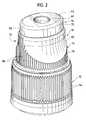
- the exterior of the sleeveis configured, upward from a cylindrical lower portion thereof which engages the base, with opposed slightly flattened finger grip areas corresponding to the opposed long sides of the elliptical top of the spout which allows for an easy manual manipulation of the sleeve.
- such opposed preferably smooth slightly arcuate grip areascan comfortably receive the lips of a consumer of the product with the container rotated relative to the lip confined sleeve to effect an alternate means for opening and closing the closure.
- one involved in physical activitysuch as bicycling, can readily access the container contents without requiring separate manual manipulation of the closure.
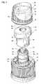
- FIG. 1is an exploded perspective view showing the three basic components of the closure, the base, the spout and the control sleeve;
- FIG. 2is a perspective view of the components assembled
- FIG. 3is a cross-sectional perspective view of the closure with the spout open
- FIG. 4is a cross-sectional perspective view of the spout closed
- FIG. 5is a bottom perspective view of the spout.
- FIG. 6is a bottom perspective view of the sleeve.
- the closure 10preferably formed of an appropriate food-compatible plastic, comprises three molded components, the base 12 , the spout 14 and the control member or sleeve 16 .
- the base 12is adapted for attachment to a container top (not shown) in known manner, such as by screw threads 18 formed on the inner surface of the cylindrical side wall 20 of the base body which mate with like threads on a container neck.
- the base bodyalso includes a top panel 22 extending inward from the body side wall 20 .
- a vertically elongate post 24normally integrally molded with the top panel 22 , extends vertically therefrom coaxial with and inwardly spaced from the surrounding body wall 20 .
- the post 24has a cylindrical side wall 26 defining a product flow passage 28 vertically therethrough and opening through the body top panel 22 .
- the post 24having a radial dimension less than that of the body side wall 20 , forms a concentric channel 30 about the post and between the post wall 26 and a sleeve retention flange 32 defined from the upper portion of the body side wall 20 peripherally thereabout and extending upward from the arcing inward over the base top panel 22 .
- This retention flangewill be explained subsequently.
- the external surface of the post wall 26includes a lower portion 34 and an upper portion 36 with an annular abutment surface or shoulder 38 formed therebetween.
- An annular sealing rib 40is formed proximate to the upper terminal end of the upper portion 36 of the post 24 and extends circumferentially about the external surface of the post.
- a closure or sealing plug 42is centrally positioned within the upper terminal end portion of the post 24 and projects vertically therefrom in radially inwardly spaced relation to the post wall.
- the plugis supported by a support spider formed of spaced radially extending spokes 44 which minimally restrict the flow if discharging product annularly about the plug 40 in its open position as shall be described subsequently.
- the lower portion 34 of the post wallis formed with a pair of diametrically opposed helical groove channels 46 .
- the base top panel 22in immediate surrounding relation to the post 24 , has an upwardly directed annular seating groove 48 formed therein. Outward of this groove, and inward of the peripheral retaining flange 32 , the top panel 22 is provided with a pair of diametrically opposed stop tabs 50 . As desired, the under surface of the top panel 22 can be provided with an annular depending sealing rib 52 adapted to engage with the top of a container neck about the opening therein. Also, and as suggested in FIG. 3, an appropriate tamper-evident skirt 54 can be provided peripherally about the lower edge of the cylindrical body wall 20 . In order to facilitate mounting of the closure, it is contemplated that the exterior surface of the body wall 20 be provided with vertical gripping ribs 56 peripherally thereabout.
- the spoutincludes a vertically elongate cylindrical side wall 58 telescopically receivable over the base post 24 .
- the spout 14has inwardly projecting helical thread segments or lugs 60 , note in particular FIGS. 1 and 5, engaged within the helical post grooves 46 which are provided with appropriate respective starting openings and terminal openings to allow for the initial engagement of the lug 60 therein upon a mounting of the spout.
- the spout 14includes a top 62 having a top panel 64 integral with and transversely across the upper end of the spout side wall 58 .
- the top panel 64extends at least partially beyond the spout side wall 58 radially outward therefrom and is of a non-circular configuration, preferably elliptical as illustrated.
- the minor dimension of the elliptical top 62will be only slightly greater than the diameter of the spout side wall 58 , while the top, at the maximum diameter thereof, will extend a substantial radial distance outward from the spout side wall 58 .
- the top 62and more particularly the top panel 64 , includes a central aperture 66 therethrough aligned with plug 42 and of a complementary configuration whereby reception of the plug 42 within the aperture 66 , as illustrated in FIG. 4, seals the aperture and prevents discharge of the product therethrough.
- the extent of vertical upward movement of the spout 14is sufficient so as to effect a complete and substantial relative withdrawal of the plug 42 from the spout 66 for product discharge.
- an inwardly directed annular sealing rib 68 on the inner surface of the spout side wall 58seats upwardly against corresponding sealing rib 40 on the base post. It is also to be appreciated that the sealing rib 40 is such as to maintain sealing engagement with the respective spout wall throughout vertical adjustment of the spout as shall be explained subsequently.
- the spout top 62also includes a continuous side skirt 70 depending from the elliptical periphery of the top panel 64 completely thereabout and in outwardly spaced relation to the spout side wall 58 at least to the opposite sides of the minimum diameter dimension of the top, again note in particular FIG. 5 .
- the lower terminal edge 72 of the spout side wall 58in the lowermost or closed position of the spout, seats within the upwardly directed annular groove 48 in the base top panel 22 , and the internal sealing rib 68 on the spout side wall 58 seats on the shoulder 38 of the base post, thereby to potentially provide an effective secondary seal location, if needed.
- the manipulation of the spout 14is effected by the control member or sleeve 16 .
- the sleeve 16includes a peripheral wall 74 with a lower cylindrical wall portion 76 having an integral outwardly directed retention lip 78 about the terminal lower edge thereof.
- the lip 78is rotatably received and retained within the upper inwardly overhanging retention flange 32 on the base wall 20 above the base panel 22 with the relationship between the retention lip 78 and retention flange 32 being such whereby the lower edge of the sleeve 16 is slidably supported on the base top panel 22 for rotation about the base.
- the sleeve wall 74is outwardly spaced from the spout side wall 26 with the skirt 70 of the spout top 62 closely and slidably received within the open upper end 80 of the sleeve 16 .
- the upper portion 82 of the sleeve wall 74gradually tapers, from the cylindrical lower wall portion 76 , to an upper elliptical configuration at the open upper end 80 thereof which closely conforms to the elliptical configuration of the top 62 of the spout 14 .
- the relationship between the configuration of the top 62 , preferably elliptical, to the correspondingly configured upper portion and open upper end of the sleeve 16is such whereby the spout, while vertically or axially movable relative to the sleeve, is confined against rotation relative thereto.
- rotation of the control member or sleeve 16will effect a simultaneous rotation of the spout 14 with the helical engagement means of the spout to the base post effecting a corresponding axial adjustment of the spout relative to both the base and the sleeve.
- the sleeve 16is provided, within the cylindrical lower portion 76 of the wall 74 thereof, with opposed radially inwardly projecting sleeve retention flanges or ribs 84 which so relate to the stop tabs or lugs 50 on the base top penal 22 as to, upon abutment therewith, limit further rotation of the sleeve and axial adjustment of the spout.
- the aforesaid positioningis such as to, of course, correspond with the extreme open and closed positions of the spout.
- gripping ribs 86are provided peripherally about the lower cylindrical portion 76 of the sleeve wall with these gripping ribs, at opposed areas of maximum diameter of the elliptical upper end of the sleeve, extending vertically for the full height of the sleeve wall. It is preferred that the opposed long sides of the upper wall portion 82 , both at the elliptical extreme upper end thereof and in the transition area above the cylindrical lower portion 76 , be without ribs, whereby opposed smooth surfaces are provided for the accommodation of the lips of a user. Such opposed smooth wide surfaces also provide convenient gripping areas for a finger manipulation of the sleeve when the closure is to be opened or closed.
- the closureis initially assembled by snap locking the three separately molded components together with the spout 14 received for rotational and axial movement on the base post 24 and the sleeve received on the base for rotational movement relative thereto.
- the spoutis retained on the post against movement beyond its maximum open position by engagement of the post and spout sealing flanges 40 and 68 , while the sleeve is retained by the engaged sleeve retaining lip 78 and base retaining flange 32 .
- the spoutcomprises the only axially adjustable member, movable from a substantially completely concealed position to a slightly elevated open position through manipulation of the separately formed control member or sleeve.
- the separate molding of the componentsallows for more efficient manufacturing procedures and the possibility of achieving economic advantages resulting therefrom.
- the formation of the closure utilizing individually molded componentsis made possible by the unique interrelationship of the components into an operating unit as described above.
Landscapes
- Engineering & Computer Science (AREA)
- Mechanical Engineering (AREA)
- Closures For Containers (AREA)
Abstract
Description
Claims (19)
Priority Applications (1)
| Application Number | Priority Date | Filing Date | Title |
|---|---|---|---|
| US09/656,431US6299038B1 (en) | 2000-09-06 | 2000-09-06 | Telescoping twist closure |
Applications Claiming Priority (1)
| Application Number | Priority Date | Filing Date | Title |
|---|---|---|---|
| US09/656,431US6299038B1 (en) | 2000-09-06 | 2000-09-06 | Telescoping twist closure |
Publications (1)
| Publication Number | Publication Date |
|---|---|
| US6299038B1true US6299038B1 (en) | 2001-10-09 |
Family
ID=24632997
Family Applications (1)
| Application Number | Title | Priority Date | Filing Date |
|---|---|---|---|
| US09/656,431Expired - LifetimeUS6299038B1 (en) | 2000-09-06 | 2000-09-06 | Telescoping twist closure |
Country Status (1)
| Country | Link |
|---|---|
| US (1) | US6299038B1 (en) |
Cited By (26)
| Publication number | Priority date | Publication date | Assignee | Title |
|---|---|---|---|---|
| US20020085957A1 (en)* | 2000-12-30 | 2002-07-04 | Moore Patrick Q. | Large mouth centrifuge labware |
| US20040118873A1 (en)* | 2002-12-23 | 2004-06-24 | Foster Donald D. | Telescoping closure |
| US20040129741A1 (en)* | 2002-07-22 | 2004-07-08 | Stoneberg Thomas C. | Beverage closure with open/close spout and protected seal surfaces |
| EP1473242A1 (en)* | 2003-04-29 | 2004-11-03 | Betapack, S.A. | Carafe tap-stopper |
| USD504826S1 (en) | 2003-12-03 | 2005-05-10 | Crown Packaging Technology, Inc. | Closure |
| US20060196894A1 (en)* | 2005-03-04 | 2006-09-07 | Lindsay Brendan J | Twist tops |
| WO2006093419A1 (en)* | 2005-03-04 | 2006-09-08 | Sistema Plastics Limited | Twist tops |
| US20070181603A1 (en)* | 2006-02-06 | 2007-08-09 | The Proctor & Gamble Company | Dispensing closure for containers |
| GB2453018A (en)* | 2007-09-24 | 2009-03-25 | Chemence Ltd | Two-part closure cap for a container |
| US20090095700A1 (en)* | 2007-10-07 | 2009-04-16 | Craig Carroll | Safety Cap and Container System |
| US7815061B1 (en) | 2006-03-31 | 2010-10-19 | Rexam Closures And Containers | Friction surface for push and turn child resistant closure |
| WO2010123382A1 (en)* | 2009-04-21 | 2010-10-28 | Sistema Plastics Limited | Dispensing closure assemblies ("spring twist") |
| US7828166B1 (en) | 2006-05-03 | 2010-11-09 | Rexam Closures And Containers Inc. | Dispensing closure with child resistant feature |
| US20110168743A1 (en)* | 2010-01-11 | 2011-07-14 | Dedoes Industries, Inc. | Paint can dispenser |
| US7988004B1 (en)* | 2008-03-19 | 2011-08-02 | Rexam Closures And Containers Inc. | Dispensing closure with tamper evident device |
| US8109396B1 (en) | 2006-03-31 | 2012-02-07 | Rexam Healthcare Packaging Inc. | Slide rails and friction surfaces for closure |
| US20120175336A1 (en)* | 2011-01-10 | 2012-07-12 | Sonoco Development, Inc. | Child resistant container |
| EP2476627A1 (en)* | 2011-01-12 | 2012-07-18 | White Horse Innovations Ltd | Nozzle arrangement fixed on a container |
| US20120305563A1 (en)* | 2011-05-31 | 2012-12-06 | Zak Designs, Inc. | Lid for a container |
| US20140144932A1 (en)* | 2006-07-07 | 2014-05-29 | Fair Oaks Farms Brands, Inc. | Liquid Food Dispenser System and Method |
| FR3031280A1 (en)* | 2015-01-06 | 2016-07-08 | Oreal | SEALED DEVICE FOR PACKAGING AND DISTRIBUTING A PRODUCT, IN PARTICULAR A COSMETIC PRODUCT |
| US9850045B2 (en)* | 2013-11-14 | 2017-12-26 | Aptar Freyung Gmbh | Dispensing closure and container with such a dispensing closure |
| US9994368B2 (en)* | 2012-10-30 | 2018-06-12 | The Procter & Gamble Company | Closure for a container |
| WO2021000821A1 (en)* | 2019-06-29 | 2021-01-07 | 东莞市顺畅塑胶瓶盖有限公司 | Helical telescopic pourer cap for containers |
| US11179008B2 (en)* | 2018-05-14 | 2021-11-23 | Aaron Wiener | Portable multi-function herb grinder |
| WO2024108282A1 (en)* | 2022-11-21 | 2024-05-30 | Aptar Do Brasil Embalagens Ltda. | Fluid transfer device |
Citations (12)
| Publication number | Priority date | Publication date | Assignee | Title |
|---|---|---|---|---|
| US3216630A (en)* | 1963-03-08 | 1965-11-09 | Stull Engraving Co | Closure for containers |
| US3231155A (en) | 1964-03-23 | 1966-01-25 | Paul H Mcconnell | Container and closure cap therefor |
| US4065037A (en)* | 1976-07-15 | 1977-12-27 | The Procter & Gamble Company | Non-spurting twist-open dispensing closure |
| US4424918A (en)* | 1981-10-16 | 1984-01-10 | Gene Stull | Non-resealable dispenser cap construction |
| US4438870A (en)* | 1981-05-20 | 1984-03-27 | Morton Stull | Captive dispensing cap construction |
| US4754899A (en)* | 1987-02-03 | 1988-07-05 | Gene Stull | Twist cap having adjustable flow rate |
| US4805807A (en)* | 1986-05-12 | 1989-02-21 | Astra Plastique | Dispensing stopper with rotating cap for pasty products |
| US4967941A (en) | 1989-04-13 | 1990-11-06 | Creative Packaging Corp. | Twist lock adjustable metering closure cap |
| US5111977A (en) | 1990-08-24 | 1992-05-12 | Maguire Paul R | Sealable and dispensing pouring spout |
| US5135139A (en) | 1987-04-10 | 1992-08-04 | Creanova Ag | Rotary cover for closing the axial opening of a hollow-cylindrical body |
| US5421487A (en) | 1992-10-27 | 1995-06-06 | Lumson S.R.L. | Dispenser cap for a fluid substance container, with a movable dispensing nozzle |
| US5947331A (en) | 1996-04-19 | 1999-09-07 | Defi International | Dispensing closure with retracting end for containers |
- 2000
- 2000-09-06USUS09/656,431patent/US6299038B1/ennot_activeExpired - Lifetime
Patent Citations (12)
| Publication number | Priority date | Publication date | Assignee | Title |
|---|---|---|---|---|
| US3216630A (en)* | 1963-03-08 | 1965-11-09 | Stull Engraving Co | Closure for containers |
| US3231155A (en) | 1964-03-23 | 1966-01-25 | Paul H Mcconnell | Container and closure cap therefor |
| US4065037A (en)* | 1976-07-15 | 1977-12-27 | The Procter & Gamble Company | Non-spurting twist-open dispensing closure |
| US4438870A (en)* | 1981-05-20 | 1984-03-27 | Morton Stull | Captive dispensing cap construction |
| US4424918A (en)* | 1981-10-16 | 1984-01-10 | Gene Stull | Non-resealable dispenser cap construction |
| US4805807A (en)* | 1986-05-12 | 1989-02-21 | Astra Plastique | Dispensing stopper with rotating cap for pasty products |
| US4754899A (en)* | 1987-02-03 | 1988-07-05 | Gene Stull | Twist cap having adjustable flow rate |
| US5135139A (en) | 1987-04-10 | 1992-08-04 | Creanova Ag | Rotary cover for closing the axial opening of a hollow-cylindrical body |
| US4967941A (en) | 1989-04-13 | 1990-11-06 | Creative Packaging Corp. | Twist lock adjustable metering closure cap |
| US5111977A (en) | 1990-08-24 | 1992-05-12 | Maguire Paul R | Sealable and dispensing pouring spout |
| US5421487A (en) | 1992-10-27 | 1995-06-06 | Lumson S.R.L. | Dispenser cap for a fluid substance container, with a movable dispensing nozzle |
| US5947331A (en) | 1996-04-19 | 1999-09-07 | Defi International | Dispensing closure with retracting end for containers |
Cited By (49)
| Publication number | Priority date | Publication date | Assignee | Title |
|---|---|---|---|---|
| US6866826B2 (en)* | 2000-12-30 | 2005-03-15 | Beckman Coulter, Inc. | Large mouth centrifuge labware |
| US20020085957A1 (en)* | 2000-12-30 | 2002-07-04 | Moore Patrick Q. | Large mouth centrifuge labware |
| US7143911B2 (en) | 2002-07-22 | 2006-12-05 | Creative Packaging Corp. | Beverage closure with open/close spout and protected seal surfaces |
| US20040129741A1 (en)* | 2002-07-22 | 2004-07-08 | Stoneberg Thomas C. | Beverage closure with open/close spout and protected seal surfaces |
| US20050040190A1 (en)* | 2002-07-22 | 2005-02-24 | Stoneberg Thomas C. | Beverage closure with open/close spout and protected seal surfaces |
| US6871764B2 (en) | 2002-07-22 | 2005-03-29 | Creaive Packaging Corp. | Beverage closure with open/close spout and protected seal surfaces |
| US20040118873A1 (en)* | 2002-12-23 | 2004-06-24 | Foster Donald D. | Telescoping closure |
| EP1473242A1 (en)* | 2003-04-29 | 2004-11-03 | Betapack, S.A. | Carafe tap-stopper |
| USD504826S1 (en) | 2003-12-03 | 2005-05-10 | Crown Packaging Technology, Inc. | Closure |
| US20060196894A1 (en)* | 2005-03-04 | 2006-09-07 | Lindsay Brendan J | Twist tops |
| US7832600B2 (en) | 2005-03-04 | 2010-11-16 | Sistema Plastics Limited | Twist tops |
| AU2010200355B2 (en)* | 2005-03-04 | 2013-07-04 | Sistema Plastics Limited | Twist Tops |
| US20090071962A1 (en)* | 2005-03-04 | 2009-03-19 | Sistema Plastics Limited | Twist tops |
| AU2009201907B2 (en)* | 2005-03-04 | 2010-12-23 | Sistema Plastics Limited | Twist Tops |
| WO2006093419A1 (en)* | 2005-03-04 | 2006-09-08 | Sistema Plastics Limited | Twist tops |
| AU2006219140B2 (en)* | 2005-03-04 | 2009-04-23 | Sistema Plastics Limited | Twist tops |
| US7677421B2 (en) | 2005-03-04 | 2010-03-16 | Sistema Plastics Limited | Twist tops |
| US20070181603A1 (en)* | 2006-02-06 | 2007-08-09 | The Proctor & Gamble Company | Dispensing closure for containers |
| US8109396B1 (en) | 2006-03-31 | 2012-02-07 | Rexam Healthcare Packaging Inc. | Slide rails and friction surfaces for closure |
| US7815061B1 (en) | 2006-03-31 | 2010-10-19 | Rexam Closures And Containers | Friction surface for push and turn child resistant closure |
| US7828166B1 (en) | 2006-05-03 | 2010-11-09 | Rexam Closures And Containers Inc. | Dispensing closure with child resistant feature |
| US11767214B2 (en) | 2006-07-07 | 2023-09-26 | Fairlife, Llc | Liquid food dispenser system and method |
| US12060256B2 (en) | 2006-07-07 | 2024-08-13 | Fairlife, Llc | Liquid food dispenser system and method |
| US9890030B2 (en)* | 2006-07-07 | 2018-02-13 | Fairlife, Llc | Liquid food dispenser system and method |
| US12275632B2 (en) | 2006-07-07 | 2025-04-15 | Fairlife, Llc | Liquid food dispenser system and method |
| US20140144932A1 (en)* | 2006-07-07 | 2014-05-29 | Fair Oaks Farms Brands, Inc. | Liquid Food Dispenser System and Method |
| US11097938B2 (en) | 2006-07-07 | 2021-08-24 | Fairlife, Llc | Liquid food dispenser system and method |
| US10562755B2 (en) | 2006-07-07 | 2020-02-18 | Fairlife, Llc | Liquid food dispenser system and method |
| US10370236B2 (en) | 2006-07-07 | 2019-08-06 | Fairlife, Llc | Liquid food dispenser system and method |
| GB2453018A (en)* | 2007-09-24 | 2009-03-25 | Chemence Ltd | Two-part closure cap for a container |
| US20090095700A1 (en)* | 2007-10-07 | 2009-04-16 | Craig Carroll | Safety Cap and Container System |
| US8205762B2 (en)* | 2007-10-07 | 2012-06-26 | Craig Carroll | Safety cap assembly and container system |
| US7988004B1 (en)* | 2008-03-19 | 2011-08-02 | Rexam Closures And Containers Inc. | Dispensing closure with tamper evident device |
| WO2010123382A1 (en)* | 2009-04-21 | 2010-10-28 | Sistema Plastics Limited | Dispensing closure assemblies ("spring twist") |
| US20110049195A1 (en)* | 2009-04-21 | 2011-03-03 | Allin Nicholas Russell | Dispensing closure assemblies |
| US8434649B2 (en)* | 2010-01-11 | 2013-05-07 | Dedoes Industries, Inc. | Paint can dispenser |
| US20110168743A1 (en)* | 2010-01-11 | 2011-07-14 | Dedoes Industries, Inc. | Paint can dispenser |
| US8333288B2 (en)* | 2011-01-10 | 2012-12-18 | Sonoco Development, Inc. | Child resistant container having cap and locking ring |
| US20120175336A1 (en)* | 2011-01-10 | 2012-07-12 | Sonoco Development, Inc. | Child resistant container |
| EP2476627A1 (en)* | 2011-01-12 | 2012-07-18 | White Horse Innovations Ltd | Nozzle arrangement fixed on a container |
| GB2487206A (en)* | 2011-01-12 | 2012-07-18 | White Horse Innovations Ltd | A nozzle for a drinks bottle made of parts relatively rotatable to open and close the nozzle |
| GB2487206B (en)* | 2011-01-12 | 2015-12-16 | White Horse Innovations Ltd | Nozzle for fluid container |
| US20120305563A1 (en)* | 2011-05-31 | 2012-12-06 | Zak Designs, Inc. | Lid for a container |
| US9994368B2 (en)* | 2012-10-30 | 2018-06-12 | The Procter & Gamble Company | Closure for a container |
| US9850045B2 (en)* | 2013-11-14 | 2017-12-26 | Aptar Freyung Gmbh | Dispensing closure and container with such a dispensing closure |
| FR3031280A1 (en)* | 2015-01-06 | 2016-07-08 | Oreal | SEALED DEVICE FOR PACKAGING AND DISTRIBUTING A PRODUCT, IN PARTICULAR A COSMETIC PRODUCT |
| US11179008B2 (en)* | 2018-05-14 | 2021-11-23 | Aaron Wiener | Portable multi-function herb grinder |
| WO2021000821A1 (en)* | 2019-06-29 | 2021-01-07 | 东莞市顺畅塑胶瓶盖有限公司 | Helical telescopic pourer cap for containers |
| WO2024108282A1 (en)* | 2022-11-21 | 2024-05-30 | Aptar Do Brasil Embalagens Ltda. | Fluid transfer device |
Similar Documents
| Publication | Publication Date | Title |
|---|---|---|
| US6299038B1 (en) | Telescoping twist closure | |
| US6135329A (en) | Universal base pull/push-twist closure | |
| US6299027B1 (en) | Valve controlled dispensing closure | |
| US6874664B1 (en) | Push-pull dispenser with folding fingers | |
| US5197634A (en) | Side orifice dispensing closure | |
| US3318496A (en) | Container closure with axial plug | |
| US5839611A (en) | Dispenser for removing a fluid from a container | |
| US2998902A (en) | Captive cap dispensing closure | |
| US6334555B1 (en) | Fitment and resealable dispensing closure assembly for high-pressure sealing and bi-modal dispensing | |
| US5139182A (en) | Closure and dispensing device for containers | |
| US4749103A (en) | Child resistant dispensing closure system | |
| KR100270895B1 (en) | Container with two position handle | |
| US5868281A (en) | Non-spill bottle cap | |
| US6065648A (en) | Child resistant dispenser | |
| US5588546A (en) | Closure with stay-open lid | |
| US5038967A (en) | Container with captive cap and internally valved closure | |
| US5016787A (en) | Side orifice dispensing closure | |
| US3351249A (en) | Captive dispensing closure for containers | |
| US6244476B1 (en) | Dispenser cap for fluid substance containers | |
| JPH0626573A (en) | Cover body for vessel | |
| US5110017A (en) | Container with captive cap and internally valved closure and positive closure seals | |
| US4691836A (en) | Apertured closure device with depressible disc portion | |
| EP1796983B1 (en) | Valve | |
| GB2283013A (en) | Hand-held dispenser with twist-to-open cap | |
| EP0887279A2 (en) | Dispenser for oil/vinegar bottle |
Legal Events
| Date | Code | Title | Description |
|---|---|---|---|
| AS | Assignment | Owner name:COURTESY CORPORATION, ILLINOIS Free format text:ASSIGNMENT OF ASSIGNORS INTEREST;ASSIGNORS:SCHMEISSER, WILLIAM C.;STONEBERG, THOMAS C.;BERGE, GARY;REEL/FRAME:011085/0935 Effective date:20000901 | |
| STCF | Information on status: patent grant | Free format text:PATENTED CASE | |
| AS | Assignment | Owner name:BANK OF AMERICA, N.A., TEXAS Free format text:SECURITY INTEREST;ASSIGNORS:COURTESY CORPORATION;CREATIVE PACKAGING CORP.;REEL/FRAME:012551/0605 Effective date:20020116 | |
| AS | Assignment | Owner name:BANK OF AMERICA, N.A., TEXAS Free format text:SECURITY AGREEMENT;ASSIGNOR:COURTESY CORPORATION; CREATIVE PACKAGING CORP.;REEL/FRAME:012539/0589 Effective date:20020116 | |
| AS | Assignment | Owner name:COURTESY CORPORATION, ILLINOIS Free format text:RELEASE OF SECURITY INTERESTS;ASSIGNOR:BANK OF AMERICA, N.A.;REEL/FRAME:013467/0936 Effective date:20021024 | |
| AS | Assignment | Owner name:WACHOVIA BANK, NATIONAL ASSOCIATION, NORTH CAROLIN Free format text:SECURITY AGREEMENT;ASSIGNOR:COURTESY CORPORATION;REEL/FRAME:013484/0050 Effective date:20021024 | |
| AS | Assignment | Owner name:CREATIVE PECKAGING CORP., ILLINOIS Free format text:ASSIGNMENT OF ASSIGNORS INTEREST;ASSIGNOR:COURTESY CORPORATION;REEL/FRAME:014363/0859 Effective date:20031229 | |
| AS | Assignment | Owner name:CREATIVE PACKAGING CORP., ILLINOIS Free format text:ASSIGNMENT OF ASSIGNORS INTEREST;ASSIGNOR:COURTESY CORPORATION;REEL/FRAME:014373/0972 Effective date:20031229 | |
| AS | Assignment | Owner name:CREATIVE PACKAGING CORP., ILLINOIS Free format text:RELEASE OF SECURITY INTEREST;ASSIGNOR:WACHOVIA BANK, NATIONAL ASSOCIATION;REEL/FRAME:015065/0799 Effective date:20040319 Owner name:WACHOVIA BANK, NATIONAL ASSOCIATEION, NORTH CAROLI Free format text:SECURITY AGREEMENT;ASSIGNOR:CREATIVE PACKAGING CORP.;REEL/FRAME:015065/0804 Effective date:20040322 | |
| FEPP | Fee payment procedure | Free format text:PAYOR NUMBER ASSIGNED (ORIGINAL EVENT CODE: ASPN); ENTITY STATUS OF PATENT OWNER: LARGE ENTITY | |
| FPAY | Fee payment | Year of fee payment:4 | |
| FPAY | Fee payment | Year of fee payment:8 | |
| AS | Assignment | Owner name:REXAM CLOSURES AND CONTAINERS INC., NORTH CAROLINA Free format text:ASSIGNMENT OF ASSIGNORS INTEREST;ASSIGNOR:CREATIVE PACKAGING CORPORATION;REEL/FRAME:028548/0802 Effective date:20110815 | |
| AS | Assignment | Owner name:REXAM CLOSURES LLC, NORTH CAROLINA Free format text:ASSIGNMENT OF ASSIGNORS INTEREST;ASSIGNOR:REXAM CLOSURES AND CONTAINERS, INC.;REEL/FRAME:028680/0204 Effective date:20110815 | |
| AS | Assignment | Owner name:BERRY PLASTICS CORPORATION, INDIANA Free format text:ASSIGNMENT OF ASSIGNORS INTEREST;ASSIGNOR:REXAM CLOSURES LLC;REEL/FRAME:028715/0215 Effective date:20120529 | |
| FPAY | Fee payment | Year of fee payment:12 | |
| AS | Assignment | Owner name:CREDIT SUISSE AG, CAYMAN ISLANDS BRANCH, NEW YORK Free format text:FIRST LIEN INTELLECTUAL PROPERTY SECURITY AGREEMENT;ASSIGNORS:AVINTIV SPECIALTY MATERIALS INC.;BERRY FILM PRODUCTS COMPANY, INC.;BERRY GLOBAL FILMS, LLC;AND OTHERS;REEL/FRAME:049121/0864 Effective date:20190501 Owner name:BANK OF AMERICA, NORTH CAROLINA Free format text:FIRST LIEN INTELLECTUAL PROPERTY SECURITY AGREEMENT;ASSIGNORS:AVINTIV SPECIALTY MATERIALS INC.;BERRY FILM PRODUCTS COMPANY, INC.;BERRY GLOBAL FILMS, LLC;AND OTHERS;REEL/FRAME:049121/0864 Effective date:20190501 | |
| AS | Assignment | Owner name:U.S. BANK NATIONAL ASSOCIATION, AS COLLATERAL AGEN Free format text:FIRST LIEN PATENT SECURITY AGREEMENT;ASSIGNORS:BERRY GLOBAL, INC.;BERRY FILM PRODUCTS COMPANY, INC.;BPREX HEALTHCARE PACKAGING INC.;AND OTHERS;REEL/FRAME:049671/0171 Effective date:20190701 Owner name:U.S. BANK NATIONAL ASSOCIATION, AS COLLATERAL AGENT, NEW YORK Free format text:FIRST LIEN PATENT SECURITY AGREEMENT;ASSIGNORS:BERRY GLOBAL, INC.;BERRY FILM PRODUCTS COMPANY, INC.;BPREX HEALTHCARE PACKAGING INC.;AND OTHERS;REEL/FRAME:049671/0171 Effective date:20190701 | |
| AS | Assignment | Owner name:BANK OF AMERICA, N.A., CONNECTICUT Free format text:FIRST LIEN INTELLECTUAL PROPERTY SECURITY AGREEMENT;ASSIGNORS:AVINTIV SPECIALTY MATERIALS INC.;BERRY FILM PRODUCTS COMPANY, INC.;BERRY GLOBAL FILMS, LLC;AND OTHERS;REEL/FRAME:049845/0054 Effective date:20190501 Owner name:CREDIT SUISSE AG, CAYMAN ISLANDS BRANCH, NEW YORK Free format text:FIRST LIEN INTELLECTUAL PROPERTY SECURITY AGREEMENT;ASSIGNORS:AVINTIV SPECIALTY MATERIALS INC.;BERRY FILM PRODUCTS COMPANY, INC.;BERRY GLOBAL FILMS, LLC;AND OTHERS;REEL/FRAME:049845/0054 Effective date:20190501 | |
| AS | Assignment | Owner name:PROVIDENCIA USA, INC., INDIANA Free format text:RELEASE BY SECURED PARTY;ASSIGNOR:U.S. BANK TRUST COMPANY, NATIONAL ASSOCIATION;REEL/FRAME:069306/0067 Effective date:20241104 Owner name:FIBERWEB, LLC., INDIANA Free format text:RELEASE BY SECURED PARTY;ASSIGNOR:U.S. BANK TRUST COMPANY, NATIONAL ASSOCIATION;REEL/FRAME:069306/0067 Effective date:20241104 Owner name:AVINTIV SPECIALTY MATERIALS, LLC (F/K/A AVINTIV SPECIALTY MATERIALS INC.; F/K/A POLYMER GROUP, INC.), INDIANA Free format text:RELEASE BY SECURED PARTY;ASSIGNOR:U.S. BANK TRUST COMPANY, NATIONAL ASSOCIATION;REEL/FRAME:069306/0067 Effective date:20241104 Owner name:BERRY FILM PRODUCTS COMPANY, INC., INDIANA Free format text:RELEASE BY SECURED PARTY;ASSIGNOR:U.S. BANK TRUST COMPANY, NATIONAL ASSOCIATION;REEL/FRAME:069306/0067 Effective date:20241104 | |
| AS | Assignment | Owner name:F&S TOOL, INC., INDIANA Free format text:RELEASE OF PATENT SECURITY INTERESTS;ASSIGNORS:UBS AG, STAMFORD BRANCH (SUCCESSOR TO CREDIT SUISSE AG, CAYMAN ISLANDS BRANCH), AS TERM LOAN COLLATERAL AGENT;BANK OF AMERICA, N.A., AS ABL COLLATERAL AGENT;REEL/FRAME:071168/0009 Effective date:20250430 Owner name:ROLLPAK CORPORATION, INDIANA Free format text:RELEASE OF PATENT SECURITY INTERESTS;ASSIGNORS:UBS AG, STAMFORD BRANCH (SUCCESSOR TO CREDIT SUISSE AG, CAYMAN ISLANDS BRANCH), AS TERM LOAN COLLATERAL AGENT;BANK OF AMERICA, N.A., AS ABL COLLATERAL AGENT;REEL/FRAME:071168/0009 Effective date:20250430 Owner name:PLIANT, LLC, INDIANA Free format text:RELEASE OF PATENT SECURITY INTERESTS;ASSIGNORS:UBS AG, STAMFORD BRANCH (SUCCESSOR TO CREDIT SUISSE AG, CAYMAN ISLANDS BRANCH), AS TERM LOAN COLLATERAL AGENT;BANK OF AMERICA, N.A., AS ABL COLLATERAL AGENT;REEL/FRAME:071168/0009 Effective date:20250430 Owner name:LETICA RESOURCES, INC., INDIANA Free format text:RELEASE OF PATENT SECURITY INTERESTS;ASSIGNORS:UBS AG, STAMFORD BRANCH (SUCCESSOR TO CREDIT SUISSE AG, CAYMAN ISLANDS BRANCH), AS TERM LOAN COLLATERAL AGENT;BANK OF AMERICA, N.A., AS ABL COLLATERAL AGENT;REEL/FRAME:071168/0009 Effective date:20250430 Owner name:LETICA CORPORATION, INDIANA Free format text:RELEASE OF PATENT SECURITY INTERESTS;ASSIGNORS:UBS AG, STAMFORD BRANCH (SUCCESSOR TO CREDIT SUISSE AG, CAYMAN ISLANDS BRANCH), AS TERM LOAN COLLATERAL AGENT;BANK OF AMERICA, N.A., AS ABL COLLATERAL AGENT;REEL/FRAME:071168/0009 Effective date:20250430 Owner name:KERR GROUP, LLC, INDIANA Free format text:RELEASE OF PATENT SECURITY INTERESTS;ASSIGNORS:UBS AG, STAMFORD BRANCH (SUCCESSOR TO CREDIT SUISSE AG, CAYMAN ISLANDS BRANCH), AS TERM LOAN COLLATERAL AGENT;BANK OF AMERICA, N.A., AS ABL COLLATERAL AGENT;REEL/FRAME:071168/0009 Effective date:20250430 Owner name:FIBERWEB, LLC, INDIANA Free format text:RELEASE OF PATENT SECURITY INTERESTS;ASSIGNORS:UBS AG, STAMFORD BRANCH (SUCCESSOR TO CREDIT SUISSE AG, CAYMAN ISLANDS BRANCH), AS TERM LOAN COLLATERAL AGENT;BANK OF AMERICA, N.A., AS ABL COLLATERAL AGENT;REEL/FRAME:071168/0009 Effective date:20250430 Owner name:FIBERWEB, INC., INDIANA Free format text:RELEASE OF PATENT SECURITY INTERESTS;ASSIGNORS:UBS AG, STAMFORD BRANCH (SUCCESSOR TO CREDIT SUISSE AG, CAYMAN ISLANDS BRANCH), AS TERM LOAN COLLATERAL AGENT;BANK OF AMERICA, N.A., AS ABL COLLATERAL AGENT;REEL/FRAME:071168/0009 Effective date:20250430 Owner name:COVALENCE SPECIALTY ADHESIVES LLC, INDIANA Free format text:RELEASE OF PATENT SECURITY INTERESTS;ASSIGNORS:UBS AG, STAMFORD BRANCH (SUCCESSOR TO CREDIT SUISSE AG, CAYMAN ISLANDS BRANCH), AS TERM LOAN COLLATERAL AGENT;BANK OF AMERICA, N.A., AS ABL COLLATERAL AGENT;REEL/FRAME:071168/0009 Effective date:20250430 Owner name:BPREX HEALTHCARE PACKAGING INC., INDIANA Free format text:RELEASE OF PATENT SECURITY INTERESTS;ASSIGNORS:UBS AG, STAMFORD BRANCH (SUCCESSOR TO CREDIT SUISSE AG, CAYMAN ISLANDS BRANCH), AS TERM LOAN COLLATERAL AGENT;BANK OF AMERICA, N.A., AS ABL COLLATERAL AGENT;REEL/FRAME:071168/0009 Effective date:20250430 Owner name:BERRY PLASTICS HOLDING CORPORATION, INDIANA Free format text:RELEASE OF PATENT SECURITY INTERESTS;ASSIGNORS:UBS AG, STAMFORD BRANCH (SUCCESSOR TO CREDIT SUISSE AG, CAYMAN ISLANDS BRANCH), AS TERM LOAN COLLATERAL AGENT;BANK OF AMERICA, N.A., AS ABL COLLATERAL AGENT;REEL/FRAME:071168/0009 Effective date:20250430 Owner name:BERRY PLASTICS FILMCO, INC., INDIANA Free format text:RELEASE OF PATENT SECURITY INTERESTS;ASSIGNORS:UBS AG, STAMFORD BRANCH (SUCCESSOR TO CREDIT SUISSE AG, CAYMAN ISLANDS BRANCH), AS TERM LOAN COLLATERAL AGENT;BANK OF AMERICA, N.A., AS ABL COLLATERAL AGENT;REEL/FRAME:071168/0009 Effective date:20250430 Owner name:BERRY PLASTICS CORPORATION, INDIANA Free format text:RELEASE OF PATENT SECURITY INTERESTS;ASSIGNORS:UBS AG, STAMFORD BRANCH (SUCCESSOR TO CREDIT SUISSE AG, CAYMAN ISLANDS BRANCH), AS TERM LOAN COLLATERAL AGENT;BANK OF AMERICA, N.A., AS ABL COLLATERAL AGENT;REEL/FRAME:071168/0009 Effective date:20250430 Owner name:BERRY GLOBAL, INC., INDIANA Free format text:RELEASE OF PATENT SECURITY INTERESTS;ASSIGNORS:UBS AG, STAMFORD BRANCH (SUCCESSOR TO CREDIT SUISSE AG, CAYMAN ISLANDS BRANCH), AS TERM LOAN COLLATERAL AGENT;BANK OF AMERICA, N.A., AS ABL COLLATERAL AGENT;REEL/FRAME:071168/0009 Effective date:20250430 Owner name:BERRY GLOBAL FILMS, LLC, INDIANA Free format text:RELEASE OF PATENT SECURITY INTERESTS;ASSIGNORS:UBS AG, STAMFORD BRANCH (SUCCESSOR TO CREDIT SUISSE AG, CAYMAN ISLANDS BRANCH), AS TERM LOAN COLLATERAL AGENT;BANK OF AMERICA, N.A., AS ABL COLLATERAL AGENT;REEL/FRAME:071168/0009 Effective date:20250430 Owner name:BERRY FILM PRODUCTS COMPANY, INC., INDIANA Free format text:RELEASE OF PATENT SECURITY INTERESTS;ASSIGNORS:UBS AG, STAMFORD BRANCH (SUCCESSOR TO CREDIT SUISSE AG, CAYMAN ISLANDS BRANCH), AS TERM LOAN COLLATERAL AGENT;BANK OF AMERICA, N.A., AS ABL COLLATERAL AGENT;REEL/FRAME:071168/0009 Effective date:20250430 Owner name:AVINTIV SPECIALTY MATERIALS, LLC (F/K/A AVINTIV SPECIALTY MATERIALS INC.), INDIANA Free format text:RELEASE OF PATENT SECURITY INTERESTS;ASSIGNORS:UBS AG, STAMFORD BRANCH (SUCCESSOR TO CREDIT SUISSE AG, CAYMAN ISLANDS BRANCH), AS TERM LOAN COLLATERAL AGENT;BANK OF AMERICA, N.A., AS ABL COLLATERAL AGENT;REEL/FRAME:071168/0009 Effective date:20250430 |