US6298320B1 - System and method for testing an embedded microprocessor system containing physical and/or simulated hardware - Google Patents
System and method for testing an embedded microprocessor system containing physical and/or simulated hardwareDownload PDFInfo
- Publication number
- US6298320B1 US6298320B1US09/024,324US2432498AUS6298320B1US 6298320 B1US6298320 B1US 6298320B1US 2432498 AUS2432498 AUS 2432498AUS 6298320 B1US6298320 B1US 6298320B1
- Authority
- US
- United States
- Prior art keywords
- target
- hardware
- processor
- monitor
- simulated
- Prior art date
- Legal status (The legal status is an assumption and is not a legal conclusion. Google has not performed a legal analysis and makes no representation as to the accuracy of the status listed.)
- Expired - Fee Related
Links
Images

Classifications
- G—PHYSICS
- G06—COMPUTING OR CALCULATING; COUNTING
- G06F—ELECTRIC DIGITAL DATA PROCESSING
- G06F11/00—Error detection; Error correction; Monitoring
- G06F11/22—Detection or location of defective computer hardware by testing during standby operation or during idle time, e.g. start-up testing
- G06F11/26—Functional testing
- G06F11/261—Functional testing by simulating additional hardware, e.g. fault simulation
Definitions
- the present inventionrelates generally to testing software and hardware in embedded systems, and, more specifically, to a system and method for testing software and hardware in embedded systems in which the hardware may be wholly or partially simulated.
- the hardware simulatoris a software program that simulates the responses of the target hardware and is implemented entirely in software.
- the target hardwareincluding the target processor, is simulated entirely by computer software.
- Another approachuses a target processor that interfaces with a hardware emulator of the target hardware.
- the hardware emulatoris typically implemented using reconfigurable hardware, such as field-programmable gate arrays, that can be programmed to perform the functions of the target hardware.
- the target programis typically executed out of a memory device used with the hardware emulator.
- the target processormay be realized using a microprocessor in a microprocessor emulator, and, in such cases, the target processor may execute the target program from memory in the microprocessor emulator.
- the target hardwareincluding the target processor, is implemented entirely in hardware, although the target processor interfaces with emulated target hardware instead of the actual target hardware.
- a communications interfacecontrols communication between a memory, a microprocessor in the emulator, and the hardware simulator.
- the microprocessorreceives target instructions from the memory and then executes the target instructions.
- the emulatorcommunicates with the hardware simulator so that the simulated target hardware interacts with the microprocessor.
- the advantages of the Bunza approachare that it is not necessary for the hardware simulator to simulate the microprocessor, thereby greatly decreasing the hardware simulation task. Further, the target code is executed at essentially normal speed until an interaction with the target hardware occurs.
- the hardware simulatoris extremely slow and cumbersome, particularly when used to simulate a complex microprocessor executing a target program. Thus, testing a complete target program is impractical due to the extremely long execution times required by the typical hardware simulator.
- the use of an actual target processor interfacing with a hardware emulatorallows a target program to be executed much faster than the hardware simulator, but it can require extensive programming of the hardware emulator to perform the functions of the target hardware.
- the Bunza approachsolves many of the above-described problems, but it can be used only with simulated target hardware. It cannot be used to test target software and hardware where the hardware is, in whole or in part, physically present in the target system.
- the target systemcan be tested before fabrication of the target hardware has started using the Bunza approach or after fabrication of the target hardware has been completed using a conventional emulator.
- a conventional emulatorthere is no satisfactory technique for allowing target software and hardware to be tested during hardware fabrication while the target hardware is only partially fabricated.
- An embedded systemmay typically include a “target processor” executing instructions in a “target program” and interacting with “target hardware” which may be an application specific integrated circuit (ASIC) or a custom integrated circuit (IC).
- ASICapplication specific integrated circuit
- ICcustom integrated circuit
- the first system prototypeincluding the target hardware and the target program, be close in form, fit, and function to the end product.
- the target hardware prototypeswould therefore ideally include the final ASIC and custom IC designs.
- the target hardware which will ultimately execute the target programdoes not exist in physical form.
- various approacheshave been developed to allow testing of target software as it interacts with target hardware before the target hardware has been physically realized.
- none of these approachesare entirely satisfactory.
- the physical target hardware and the target software of a target systemare typically brought together for the first time when the prototype target hardware has been fabricated.
- the target program loaded at the time of the integration of the prototype target hardware and softwaredoes not work. It is common to find that the integration problems are strictly due to software complications alone. This may cause a significant delay in the software development due to the problems in the target program.
- the present inventionis embodied in a system and method for testing embedded electronic systems that include a target processor, a memory containing a target program executed by the target processor, and target hardware, part of which may be physically present and coupled to the target processor.
- the testing systemincludes a target monitor coupled to the target processor, and a communications interface coupling the target monitor to a hardware simulator that is configured to simulate the portion of the target hardware that is not yet physically present in the embedded system.
- the target monitordetermines when the target processor is attempting to access the simulated portion of the target hardware or the simulated portion of the target hardware is attempting to access the target processor.
- the target monitorUpon detecting an access to the simulated target hardware, the target monitor causes the target processor to suspend execution of the target program.
- the target monitorthen converts output signals from the target processor that are directed to the simulated hardware to corresponding output data.
- the output datais transferred through the communications interface to the hardware simulator where the data is processed in the same manner that the corresponding signals from the target processor would be processed by the target hardware if it were physically present in the embedded system.
- the hardware simulatorWhen the simulated target hardware attempts to access the target processor or respond to an access by the target processor, the hardware simulator generates input data corresponding to signals that would be generated by the target hardware if physically present in the embedded system.
- the input dataare coupled through the communications interface to the target monitor where they are converted to signals that are applied to the target processor.
- the signalsare the same as the signals that would be generated by the target hardware if it was physically present in the embedded system.
- the target processoraccesses target hardware that is physically present in the embedded system in the same manner that it would in the embedded system after all of the target hardware has been fabricated.
- the target monitorpreferably detects an access to the simulated physical hardware in either of two modes. In the first mode, the target monitor detects that the target processor has issued an address that is in the address space of the simulated target hardware. In the second mode, the target monitor detects a failure of target hardware to return an acknowledgment signal within a predetermined time in response to an access, as is normally done in response to an access by the target processor.
- An access to an address in the address space of the simulated target hardwareis preferably detected using a mapping memory, and an address comparator.
- the mapping memoryrecords addresses in the address space of the simulated target hardware, and the address comparator compares each address on the address bus of the target processor to addresses recorded in the mapping memory.
- the target monitorsuspends execution of the target program and causes the access to be processed by the hardware simulator as described above.
- the lack of an acknowledgment signalis preferably detected by a control signal monitor and a timer.
- the control signal monitormonitors a terminal on the target processor that is adapted to receive the acknowledgment signal from the physical target hardware in the event of an access to the physical target hardware by the target processor.
- the control signal monitorgenerates a detect signal in response to receiving the acknowledgment signal.
- the timerinitiates a timing period responsive to an access by the target processor to the target hardware. Unless the detect signal has been received within a predetermined period after initiating the timing period, the timer suspends execution of the target program and causes the access to be processed by the hardware simulator as described above.
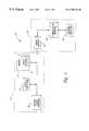
- FIG. 1is a block diagram of one embodiment of a system and method for testing an embedded system containing a target processor and physical and/or simulated hardware in accordance with one embodiment of the invention.
- FIG. 2is a detailed block diagram of one embodiment of the testing system of FIG. 1 .
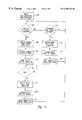
- FIG. 3is a flow chart of software that is executed by a control processor in the testing system of FIG. 2 to perform a method in accordance with one embodiment of the invention.
- An embedded system 10includes a target processor 12 coupled to a memory 14 that contains at least a target program 16 for execution by the target processor 12 .
- the memory 14may also include other program instructions and/or data for use by the target processor 12 .
- the memory 14may be read only memory (“ROM”), random access memory (“RAM”), or a combination of ROM and RAM.
- physical target hardware 20which consists of the target hardware that has already been implemented. The remaining portion of the target hardware that is not included in the physical target hardware 20 is simulated, as explained below.
- a system 30 for testing the embedded system 10includes a target monitor 32 , a communications interface 34 , and a hardware simulator 36 that is coupled to the target monitor 32 through the communications interface 34 .
- the hardware simulator 36is a conventional device that simulates the portion of the target hardware that is not included in the physical target hardware 20 .
- the hardware simulatormay be implemented by a host computer executing a properly configured hardware simulation program.
- the target processor 12executes the target program 16 thereby causing the target processor 12 to access both the physical target hardware 20 and simulated target hardware.
- the target processor 12accesses the physical target hardware 20 in the normal manner, since the physical target hardware 20 is actually present in the embedded system 10 .
- the target processor 12cannot access the simulated portion of the target hardware in the normal manner since the simulated target hardware has not yet been implemented.
- the target processor 12When the target processor 12 attempts to access target hardware other than the physical target hardware 20 , the target processor 12 instead accesses the testing system 30 . More specifically, the target monitor 32 monitors appropriate terminals on the target processor 12 , as explained below, to determine when the target processor 12 is attempting to access target hardware that is not included in the physical target hardware 20 . The target monitor 32 then converts to output signals from the target processor 12 to corresponding output data. The output data is coupled through the communications interface 34 to the hardware simulator 36 . The hardware simulator 36 then processes the output data in the same manner that target hardware, if physically present in the embedded system 10 , would process the output signals from the target processor 12 . In some cases, the target hardware is adapted to respond to the output signals from the target processor 12 by returning signals to the target processor 12 .
- the target hardwaremay initiate an interaction with the target processor 12 .
- the hardware simulator 36generates input data that is coupled through the communications interface 34 to the target monitor 32 .
- the target monitor 32then converts the input data to corresponding input signals that are applied to appropriate terminals of the target processor 12 .
- the input signalsare identical to the input signals that would be applied to the target processor 12 if the simulated target hardware was instead physically present in the embedded system 10 .
- the target monitor 32applies appropriate control signals to the target processor 12 to suspend execution of the target program 16 .
- execution of the target program 16proceeds in the same order that the target programs 16 would be executed if the simulated target hardware was instead a part of the physical target hardware 20 .
- the target processormay service interrupts with various interrupt routines. This is accomplished by holding the target processor 12 in an extended wait state and suspending execution of the target program. In particular, the bus cycle is terminated and there is an immediate vector to an exception handler that the customer links into the target program.
- the exception handleressentially sits in a poling loop waiting for the hardware simulator 36 to complete processing of an access to simulated target hardware. During this poling loop, any other exceptions that need to be serviced by the target processor 12 can be. When the hardware simulator 36 responds, the poling loop is exited, the bus cycle that caused the access to the simulated target hardware is recreated, and the exception handler is exited. This process is typically performed only for a read access to the simulated target hardware 36 because a write access does not depend on receiving data from the simulated target hardware to properly complete the bus cycle. Thus, the target processor 12 may be somewhat multitasking.
- target processor 12 and memory 14are shown in FIG. 1 as it being stand-alone components, it will be understood that they may instead be part of a conventional emulator (not shown) that is plugged into an embedded system 10 containing the physical target hardware 20 .
- the target monitor 32may determine when the target processor 12 is attempting to access target hardware that is not a part of the physical target hardware 20 .
- the target monitor 32may record the addresses that are in the address space of the simulated target hardware. The target monitor 32 may then monitor the address bus of the target processor 12 . In the event the target processor 12 outputs an address that is in the address space of the simulated hardware, the target monitor 32 captures the signals on the data and control buses of the target processor 12 and applies one or more control signals to the target processor 12 to suspend execution of the target program 16 until the access to the simulated hardware has been completed.
- the target monitor 32may monitor the signal line on which the acknowledge or other signal is coupled to the target processor 12 .
- the target monitor 32can treat the access as an access to simulated target hardware since there is apparently no physical target hardware 20 in the embedded system 10 to return the acknowledge or other signal.
- the target monitor 32includes: (a) a target interface circuit 40 that is coupled to the address, control and data buses of the target processor 12 (FIG. 1 ); (b) an access detector 42 for detecting when the target processor 12 is attempting to access simulated target hardware; (c) a bus capture and driver circuit 44 that captures signals from the target processor 12 and generates signals that are applied to the target processor 12 ; (d) a control processor 46 for controlling the operation of the target monitor 32 ; (e) a ROM 48 containing a program that is executed by the processor 46 ; and (f) a RAM 50 used by the processor 46 to store data.
- the processor 46also includes a communications port 54 that is coupled to the communications interface 34 .
- the communications interface 34includes a conventional Ethernet driver 66 and an Ethernet connector 68 that mates with a conventional Ethernet connector (not shown) of the hardware simulator 36 (FIG. 1 ).
- the target interface circuit 40includes a target address bus buffer 70 , a target control bus buffer 72 and a target data bus buffer 74 .
- the target address bus buffer 70receives address signals from the address bus of the target processor 12 and couples the signals to an internal address bus 80 .
- the target data bus buffer 74coupled data signals between the data bus of the target processor 12 and an internal data bus 94 .
- the target control bus buffer 72couples at least some control signals between the control bus of the target processor 12 and an internal control bus 82 .
- One of the control signals coupled from the target processor 12 to internal control bus 82is a target clock signal that is coupled to a target clock line 90 .
- the system 30also includes a target clock control circuit 86 that also receives the target clock signal and applies it to a target data/control bus buffer control circuit 88 .
- the target data/control bus buffer control circuit 88selectively enables the target control bus buffer 72 and the target data bus buffer 74 in synchronism with the target clock signal to capture control and data signals from the target processor 12 and apply control and data signals to the target processor 12 at the proper time.
- the target clock control circuit 86 and the target data/control bus buffer control circuit 88may be integrated into the embedded system 10 for test purposes. It is then possible to devise the target clock control circuit 86 so that it can decouple the target clock signal from the target processor 12 . When the target clock signal is decoupled from the target processor 12 , the target processor 12 suspends execution of the target program 16 .
- the target clock control circuitthus provides one means of causing the target processor 12 to suspend execution of the target program 16 when the hardware simulator 36 is processing an access to the simulated target hardware.
- the internal address bus 80is coupled to the access detector 42 and to a target address bus latch 100 in the bus capture and driver circuit 44 .
- the target address bus latch 100captures address signals from the target address bus buffer 70 and couples those address signals to the control processor 46 .
- the access detector 42examines the address signals on the internal address plus 80 to determine if the target processor 12 is attempting to access simulated target hardware.
- the internal control bus 82 and the target clock line 90are coupled to the access detector 42 , although the internal control bus 82 is also coupled to a target control bus latch 112 in the bus capture and driver circuit 44 .
- the access detector 42examines certain control signals on the internal control bus 82 over a pre-determined number of cycles of the target clock signal to determine when physical target hardware 20 is not present in the embedded system 10 to return an acknowledge signal in response to an attempted access to target hardware. In this manner, the access detector 42 determines that the attentive access to target hardware is an access to simulated target hardware.
- the target control bus latch 112is used to capture signals on the terminals of the target processor, such as a R/W* signal to specify whether an access to the simulated target hardware is a read or a write access.
- the target control bus latch 112is also used to output one or more control signals that are applied to terminals of the target processor 12 , such as a control signal to suspend execution of the target program 16 (FIG. 1 ). For example, during the period that the hardware simulator 36 is processing an access to the simulated target hardware, the target control bus latch 112 can output an inactive READY signal to an Intel® processor or an inactive data strobe acknowledge DSACK signal to an Motorola® processor used at the target processor 12 .
- the internal data bus 94is coupled to a target data bus latch 102 in the bus capture and driver circuit 44 .
- the target data bus latch 102outputs data signals to the internal data bus 94 and stores data bus signals from the internal data bus 94 .
- the bus capture and driver circuit 44includes a monitor control latch 110 and an address decoder 114 .
- the address decoder 114decodes addresses from the control processor 46 corresponding to each of the latches 100 - 112 .
- the control processorstores signals or receives signals from a specific one of the latches 100 - 112 by outputting an address corresponding to the specific latch.
- the control processor 46applies the signals to be stored in the latch 100 - 112 being accessed or receives signals from the latch 100 - 112 being accessed via a data bus 122 .
- the control processor 46also applies appropriate control signals to the address decoder via a control bus 124 .
- the monitor control latch 110receive signals from the control processor 46 that are used to control the operation of the latches 100 , 102 , and 112 .
- the access detector 42determines that the target processor 12 is attempting to access simulated target hardware, it applies a signal to the monitor control latch 110 .
- the monitor control latch 110then causes the other latches 100 , 102 , and 112 to capture the address, control and data signals, respectively, from the target processor 12 .
- the monitor control latch 110also applies control signals to the buffer control circuit 88 and control signals to the access detector 42 .
- the access detector 42includes a mapping RAM 130 and a timeout circuit 132 .
- the mapping RAM 130detects an access to simulated target hardware by detecting an address from the target processor 12 that is in the address space of the simulated target hardware.
- the timeout circuit 132detects an access to simulated target hardware by determining that there is no target hardware in the embedded system 10 that has responded to an access to target hardware with an acknowledgment signal within a pre-determined time.
- the mapping RAM 130includes an address multiplexer 140 that couples either the address bus 120 of the control processor 46 or the internal address bus 80 to a map RAM 142 .
- the address multiplexer 140allows the map RAM 130 to be accessed by either the control processor 46 through its address bus 120 or the target processor 12 through its address bus (not shown), the target address bus buffer 70 , and the internal address bus 80 .
- the address multiplexer 140 and the data multiplexer 142are controlled by the control processor 46 , which stores appropriate control signals in the monitor control latch 110 that are applied to the address multiplexer 140 and the data multiplexer 142 .
- the map RAM 142is initially programmed the address multiplexer 140 coupling the address bus 120 of the control processor 46 and the data multiplexer 144 coupling the data bus 122 of the control processor 46 to the map RAM 142 .
- the control processor 46then stores a bit at each address in the address space of the target processor 12 .
- the stored bit at each addressis a logic “0” if that address is in the address space of the physical target hardware 20 while the stored bit at each address is a logic “1” if the address is in the address space of the simulated target hardware.
- the address multiplexer 140couples the internal address bus 80 to the map RAM 142 and the data bit from the map RAM 142 to the OR gate 150 .
- the addresses output by the target processor 12are coupled through the target address bus buffer 70 , the internal address bus 80 , and the address multiplexer 140 to the map RAM 142 .
- Each address from the target processor 46thus accesses the map RAM 142 , thereby causing the map RAM 142 to output a data bit stored at that address.
- the data bitis either a logic “0” specifying that the address is in the address space of the physical target hardware 20 or a logic “1” specifying that the address is in the address space of the simulated target hardware. If the address output by the target processor 12 is in the address space of the simulated target hardware, the OR gate 150 outputs a logic “1”.
- the timeout counter 132includes a target clock counter 160 and a counter control circuit 162 .
- the target clock counter 160increments to a terminal count from an initial count that is pre-loaded by the counter control circuit 162 .
- the counter control circuit 162also selectively enables the target clock counter 160 . When the target clock counter 160 reaches the terminal count, it outputs a logic “1” thereby causing the OR gate 150 to output a logic “1”.
- the counter control circuit 162stores the initial count responsive to the monitor control latch 110 outputting an appropriate control signal.
- the counter control circuit 162then stores the initial count from the data bus 122 of the control processor 46 .
- the counter control circuit 162then pre-loads the initial count into the target clock counter 160 , and the target clock counter 160 increments responsive to the target clock signal from the target bus control buffer 72 .
- the counter control circuit 162allows the target clock counter 160 to increment only after the monitor control latch 110 has applied an appropriate control signal to the counter control circuit 162 signifying that the target processor 12 has attempted to access the target hardware (either physical 20 or simulated). If the target processor 12 is accessing the physical target hardware 20 , the physical target hardware 20 will return an acknowledge signal that is applied to the counter control circuit 162 from the target control bus buffer 72 .
- the acknowledge signalcauses the counter control circuit 162 to disable the target clock counter 160 so that the target clock counter 160 never reaches the terminal count.
- the target clock counter 160never outputs a logic “1”. If, however, there is no physical target hardware at the address being accessed by the target hardware 12 , no physical target hardware will return an acknowledge signal. As a result, the target clock counter 160 will increment to the terminal count, thereby causing the target clock counter to output a logic “1”. The OR gate 150 will then output a logic “1.” Therefore, the OR gate 150 will output a logic “1” whenever the mapping RAM 130 or the timeout counter 132 detects that the target processor 12 is attempting to access simulated target hardware.
- the output of the OR gate 150is applied to a decode/controller notification circuit 170 that, in turn, applies an appropriate control signal to the monitor control latch 110 .
- the monitor control latch 110then causes the bus latches 100 , 102 , and 112 to capture address, data, and control signals from the target processor 12 .
- the address, data, and control signalsare then coupled from the latches 100 , 102 , and 112 to the control processor 46 , which converts the signals to corresponding output data.
- the output datais coupled through the communications interface 34 to the hardware simulator 36 , which processes the data in a manner corresponding to the manner that physical target hardware would process the address, data, and control signals from the control processor if the physical target hardware was actually present in the embedded system 10 .
- the hardware simulator 36send input data to the control processor 46 through the communications interface 34 .
- the hardware simulator 36then converters the input data to corresponding data and control signals, and stores these signals in the data and control bus latches 102 and 112 , respectively.
- the latches, 102 and 112apply these signals to the target processor 12 through the target data and control bus buffers 74 and 72 , respectively.
- the target processor 12thus receives the same signals that it would receive if the simulated target hardware was physically present in the embedded system 10 .
- an interaction between the target processor 12 and the simulated target hardwareis initiated by the target processor 12 , the interaction is detected by the access detector 42 , as explained above. However, if an interaction between the target processor 12 and the simulated target hardware is initiated by the simulated target hardware, the access detector 42 will be unable to detect the interaction because the access detector 42 can only detect accesses initiated by the target processor 12 . As is customary in embedded system design, an interaction between the target hardware and the target processor is initiated by the target hardware applying an interrupt signal to the target processor. The target processor then executes an interrupt routine that is part of the target program.
- the hardware simulator 36will send input data to the control processor 36 that is indicative of an interrupt.
- the control processor 46will then convert the input data to an interrupt signal, and store the interrupt signal in the target control bus latch 112 .
- the target control bus latch 112applied the interrupt signal to the interrupt terminal of the target processor 12 through the target control bus buffer 72 .
- the target processor 12then executes an interrupt routine that is stored in the flash ROM 48 as part of the target program 16 .
- the target processor 12executes the interrupt routine in the same manner that it would had the physical target hardware 20 generated the interrupt signal instead of the simulated target hardware.
- the target processor 12response to an interaction initiated by the target hardware in the same manner regardless of whether the target hardware is physical target hardware 20 or simulated target hardware.
- FIG. 3is a flow chart of the software stored in the flash ROM 48 that is executed by the control processor 46 .
- the programis entered at 180 in which the control processor 46 sets up communications with the hardware simulator 36 .
- the program executed by the control processor 46then proceeds to step 184 where it causes the control processor 46 to examine the output of the hit decode/controller notification circuit 170 coupled through the monitor control latch 110 .
- the hit decode/controller notification circuit 170will output a signal indicative of an access to simulated target hardware.
- the programbranches from 184 to step 188 in which the signals on the buses of the target processor 12 are captured, as explained above.
- the control processor 46Upon receiving the captured signals from the target processor 12 , the control processor 46 converts the signals to corresponding output data at step 190 .
- the control processor 46then sends the data to the hardware simulator 36 (FIG. 1) at step 192 .
- the hardware simulator 36then processes the data in the same manner that the actual signals output by the target processor 12 would be processed by physical target hardware that is being stimulated in the hardware simulator 36 .
- the programremains in a loop at step 196 .
- the hardware simulator 36sends input data to the control processor 46 at step 200 .
- the control processor 46formats the input data into corresponding signals, such as an acknowledge signal, at step 202 , and the signals are sent to the target processor 12 at step 204 .
- the programthen returns to step 184 to await another access to the simulated target hardware by the target processor 12 .
- control processor 46when an interaction between the target processor 12 and the simulated target hardware is initiated by the target processor 12 .
- the interaction between the target processor 12 and the target hardwaremay be initiated by the target hardware.
- the control processor 46if the control processor 46 does not detect that the target processor 12 is attempting to access simulated target hardware, the program executed by the control processor 46 branches to step 210 .
- the control processor 46detects input data from the target hardware simulator 36 corresponding to an interrupt signal.
- the interrupt signalis the same signal that the target hardware being simulated, if physically present in the embedded system 10 , would apply to the target processor 12 .
- the input dataare applied to the control processor 46 at step 212 .
- the input datamay correspond to signals that would be applied to the target processor 12 by the target hardware, if physically present in the embedded system 10 in addition to an interrupt signal.
- the control processor 46formats the data into corresponding signals at step 214 .
- the signalsare sent through the bus capture and driver circuit 44 to the target processor 12 at step 218 .
- the testing system 30is able to analyze and test an embedded system even though only a portion of the target hardware has been fabricated and is physically present in the embedded system.
- the interaction between the target software and the target hardwarecan be tested before all of the target hardware has been physically realized, and the target hardware can be tested as it is developed and physically placed in the embedded system.
Landscapes
- Engineering & Computer Science (AREA)
- Computer Hardware Design (AREA)
- General Engineering & Computer Science (AREA)
- Theoretical Computer Science (AREA)
- Quality & Reliability (AREA)
- Physics & Mathematics (AREA)
- General Physics & Mathematics (AREA)
- Test And Diagnosis Of Digital Computers (AREA)
- Debugging And Monitoring (AREA)
Abstract
Description
Claims (28)
Priority Applications (4)
| Application Number | Priority Date | Filing Date | Title |
|---|---|---|---|
| US09/024,324US6298320B1 (en) | 1998-02-17 | 1998-02-17 | System and method for testing an embedded microprocessor system containing physical and/or simulated hardware |
| JP03913699AJP3715456B2 (en) | 1998-02-17 | 1999-02-17 | System and method for testing an embedded microprocessor system that includes physical and / or simulated hardware |
| EP99103118AEP0936550A2 (en) | 1998-02-17 | 1999-02-17 | System and method for testing an embedded microprocessor system containing simulated hardware |
| US09/916,148US7089170B2 (en) | 1998-02-17 | 2001-07-25 | System and method for testing an embedded microprocessor system containing physical and/or simulated hardware |
Applications Claiming Priority (1)
| Application Number | Priority Date | Filing Date | Title |
|---|---|---|---|
| US09/024,324US6298320B1 (en) | 1998-02-17 | 1998-02-17 | System and method for testing an embedded microprocessor system containing physical and/or simulated hardware |
Related Child Applications (1)
| Application Number | Title | Priority Date | Filing Date |
|---|---|---|---|
| US09/916,148DivisionUS7089170B2 (en) | 1998-02-17 | 2001-07-25 | System and method for testing an embedded microprocessor system containing physical and/or simulated hardware |
Publications (1)
| Publication Number | Publication Date |
|---|---|
| US6298320B1true US6298320B1 (en) | 2001-10-02 |
Family
ID=21820005
Family Applications (2)
| Application Number | Title | Priority Date | Filing Date |
|---|---|---|---|
| US09/024,324Expired - Fee RelatedUS6298320B1 (en) | 1998-02-17 | 1998-02-17 | System and method for testing an embedded microprocessor system containing physical and/or simulated hardware |
| US09/916,148Expired - LifetimeUS7089170B2 (en) | 1998-02-17 | 2001-07-25 | System and method for testing an embedded microprocessor system containing physical and/or simulated hardware |
Family Applications After (1)
| Application Number | Title | Priority Date | Filing Date |
|---|---|---|---|
| US09/916,148Expired - LifetimeUS7089170B2 (en) | 1998-02-17 | 2001-07-25 | System and method for testing an embedded microprocessor system containing physical and/or simulated hardware |
Country Status (3)
| Country | Link |
|---|---|
| US (2) | US6298320B1 (en) |
| EP (1) | EP0936550A2 (en) |
| JP (1) | JP3715456B2 (en) |
Cited By (59)
| Publication number | Priority date | Publication date | Assignee | Title |
|---|---|---|---|---|
| US20010041974A1 (en)* | 1998-02-17 | 2001-11-15 | Buckmaster Michael R. | System and method for testing an embedded microprocessor system containing physical and/or simulated hardware |
| US20010056555A1 (en)* | 1999-12-21 | 2001-12-27 | Douglas Deao | Data exchange system and method for processors |
| US6564178B1 (en)* | 1999-04-13 | 2003-05-13 | Hewlett-Packard Company | Method and apparatus for evaluating processors for architectural compliance |
| US6658600B1 (en)* | 2000-04-24 | 2003-12-02 | Microsoft Corporation | Target control abstraction for debugging embedded systems |
| US20040102944A1 (en)* | 2002-11-25 | 2004-05-27 | Richard Shortz | System and method for detecting accesses to non-existing hardware entities using architectural simulation |
| US20040111252A1 (en)* | 2002-06-26 | 2004-06-10 | Emulation And Verification Engineering | Method and system for emulating a design under test associated with a test environment |
| US20040117171A1 (en)* | 2002-12-17 | 2004-06-17 | Richard Shortz | System and method for managing access to a controlled space in a simulator environment |
| US20040133821A1 (en)* | 2003-01-07 | 2004-07-08 | Richard Shortz | System and method for detecting and isolating certain code in a simulated environment |
| US6810373B1 (en)* | 1999-08-13 | 2004-10-26 | Synopsis, Inc. | Method and apparatus for modeling using a hardware-software co-verification environment |
| US6973417B1 (en)* | 1999-11-05 | 2005-12-06 | Metrowerks Corporation | Method and system for simulating execution of a target program in a simulated target system |
| US20060015785A1 (en)* | 2004-07-15 | 2006-01-19 | Byoung-Ok Chun | Test apparatus for mixed-signal semiconductor device |
| US7017097B1 (en) | 2002-09-24 | 2006-03-21 | Cypress Semiconductor Corp. | Simultaneously driving a hardware device and a software model during a test |
| US20060101495A1 (en)* | 2004-11-05 | 2006-05-11 | William Yoshida | Device evaluation using media access control emulator |
| US7076420B1 (en)* | 2000-10-26 | 2006-07-11 | Cypress Semiconductor Corp. | Emulator chip/board architecture and interface |
| US7100152B1 (en) | 2000-01-31 | 2006-08-29 | Freescale Semiconductor, Inc. | Software analysis system having an apparatus for selectively collecting analysis data from a target system executing software instrumented with tag statements and method for use thereof |
| WO2009031737A1 (en)* | 2007-09-09 | 2009-03-12 | Geon Kim | Universal high-speed real-time monitoring device for embedded systems |
| US7526422B1 (en) | 2001-11-13 | 2009-04-28 | Cypress Semiconductor Corporation | System and a method for checking lock-step consistency between an in circuit emulation and a microcontroller |
| US20090265695A1 (en)* | 2008-04-18 | 2009-10-22 | Nec Corporation | Method and apparatus for analyzing program execution path |
| US7737724B2 (en) | 2007-04-17 | 2010-06-15 | Cypress Semiconductor Corporation | Universal digital block interconnection and channel routing |
| US7761845B1 (en) | 2002-09-09 | 2010-07-20 | Cypress Semiconductor Corporation | Method for parameterizing a user module |
| US7765095B1 (en) | 2000-10-26 | 2010-07-27 | Cypress Semiconductor Corporation | Conditional branching in an in-circuit emulation system |
| US7770113B1 (en) | 2001-11-19 | 2010-08-03 | Cypress Semiconductor Corporation | System and method for dynamically generating a configuration datasheet |
| US7774190B1 (en) | 2001-11-19 | 2010-08-10 | Cypress Semiconductor Corporation | Sleep and stall in an in-circuit emulation system |
| US7825688B1 (en) | 2000-10-26 | 2010-11-02 | Cypress Semiconductor Corporation | Programmable microcontroller architecture(mixed analog/digital) |
| US7844437B1 (en) | 2001-11-19 | 2010-11-30 | Cypress Semiconductor Corporation | System and method for performing next placements and pruning of disallowed placements for programming an integrated circuit |
| US7893724B2 (en) | 2004-03-25 | 2011-02-22 | Cypress Semiconductor Corporation | Method and circuit for rapid alignment of signals |
| US20110083121A1 (en)* | 2009-10-02 | 2011-04-07 | Gm Global Technology Operations, Inc. | Method and System for Automatic Test-Case Generation for Distributed Embedded Systems |
| US8026739B2 (en) | 2007-04-17 | 2011-09-27 | Cypress Semiconductor Corporation | System level interconnect with programmable switching |
| US8040266B2 (en) | 2007-04-17 | 2011-10-18 | Cypress Semiconductor Corporation | Programmable sigma-delta analog-to-digital converter |
| US8049569B1 (en) | 2007-09-05 | 2011-11-01 | Cypress Semiconductor Corporation | Circuit and method for improving the accuracy of a crystal-less oscillator having dual-frequency modes |
| US8067948B2 (en) | 2006-03-27 | 2011-11-29 | Cypress Semiconductor Corporation | Input/output multiplexer bus |
| US8069428B1 (en) | 2001-10-24 | 2011-11-29 | Cypress Semiconductor Corporation | Techniques for generating microcontroller configuration information |
| US8069405B1 (en) | 2001-11-19 | 2011-11-29 | Cypress Semiconductor Corporation | User interface for efficiently browsing an electronic document using data-driven tabs |
| US8069436B2 (en) | 2004-08-13 | 2011-11-29 | Cypress Semiconductor Corporation | Providing hardware independence to automate code generation of processing device firmware |
| US8078894B1 (en) | 2007-04-25 | 2011-12-13 | Cypress Semiconductor Corporation | Power management architecture, method and configuration system |
| US8078970B1 (en) | 2001-11-09 | 2011-12-13 | Cypress Semiconductor Corporation | Graphical user interface with user-selectable list-box |
| US20110307233A1 (en)* | 1998-08-31 | 2011-12-15 | Tseng Ping-Sheng | Common shared memory in a verification system |
| US8085100B2 (en) | 2005-02-04 | 2011-12-27 | Cypress Semiconductor Corporation | Poly-phase frequency synthesis oscillator |
| US8085067B1 (en) | 2005-12-21 | 2011-12-27 | Cypress Semiconductor Corporation | Differential-to-single ended signal converter circuit and method |
| US8089461B2 (en) | 2005-06-23 | 2012-01-03 | Cypress Semiconductor Corporation | Touch wake for electronic devices |
| US8092083B2 (en) | 2007-04-17 | 2012-01-10 | Cypress Semiconductor Corporation | Temperature sensor with digital bandgap |
| US8103496B1 (en) | 2000-10-26 | 2012-01-24 | Cypress Semicondutor Corporation | Breakpoint control in an in-circuit emulation system |
| US8103497B1 (en) | 2002-03-28 | 2012-01-24 | Cypress Semiconductor Corporation | External interface for event architecture |
| US8120408B1 (en) | 2005-05-05 | 2012-02-21 | Cypress Semiconductor Corporation | Voltage controlled oscillator delay cell and method |
| US8130025B2 (en) | 2007-04-17 | 2012-03-06 | Cypress Semiconductor Corporation | Numerical band gap |
| US8149048B1 (en) | 2000-10-26 | 2012-04-03 | Cypress Semiconductor Corporation | Apparatus and method for programmable power management in a programmable analog circuit block |
| US8160864B1 (en) | 2000-10-26 | 2012-04-17 | Cypress Semiconductor Corporation | In-circuit emulator and pod synchronized boot |
| US8176296B2 (en) | 2000-10-26 | 2012-05-08 | Cypress Semiconductor Corporation | Programmable microcontroller architecture |
| US8244512B1 (en)* | 1998-08-31 | 2012-08-14 | Cadence Design Systems, Inc. | Method and apparatus for simulating a circuit using timing insensitive glitch-free (TIGF) logic |
| US8286125B2 (en) | 2004-08-13 | 2012-10-09 | Cypress Semiconductor Corporation | Model for a hardware device-independent method of defining embedded firmware for programmable systems |
| US8402313B1 (en) | 2002-05-01 | 2013-03-19 | Cypress Semiconductor Corporation | Reconfigurable testing system and method |
| US8499270B1 (en) | 2007-04-25 | 2013-07-30 | Cypress Semiconductor Corporation | Configuration of programmable IC design elements |
| US8516025B2 (en) | 2007-04-17 | 2013-08-20 | Cypress Semiconductor Corporation | Clock driven dynamic datapath chaining |
| US8527949B1 (en) | 2001-11-19 | 2013-09-03 | Cypress Semiconductor Corporation | Graphical user interface for dynamically reconfiguring a programmable device |
| US9448964B2 (en) | 2009-05-04 | 2016-09-20 | Cypress Semiconductor Corporation | Autonomous control in a programmable system |
| US9564902B2 (en) | 2007-04-17 | 2017-02-07 | Cypress Semiconductor Corporation | Dynamically configurable and re-configurable data path |
| US20170139869A1 (en)* | 2015-11-13 | 2017-05-18 | Sandel Avionics, Inc. | Avionics system, architecture, and method |
| US9720805B1 (en) | 2007-04-25 | 2017-08-01 | Cypress Semiconductor Corporation | System and method for controlling a target device |
| US10698662B2 (en) | 2001-11-15 | 2020-06-30 | Cypress Semiconductor Corporation | System providing automatic source code generation for personalization and parameterization of user modules |
Families Citing this family (9)
| Publication number | Priority date | Publication date | Assignee | Title |
|---|---|---|---|---|
| DE10329147A1 (en)* | 2003-06-27 | 2005-01-20 | Siemens Ag | Linking and displaying signals of a device for hardware simulation and elements of a listing of a program |
| US8849642B2 (en)* | 2004-12-14 | 2014-09-30 | The Mathworks, Inc. | Signal definitions or descriptions in graphical modeling environments |
| EP1864219A1 (en)* | 2006-02-28 | 2007-12-12 | Mentor Graphics Corporation | Monitoring physical parameters in an emulation environment |
| CN100523856C (en)* | 2006-10-18 | 2009-08-05 | 英业达股份有限公司 | Simulation jig of electronic component and power supply abnormality detection method |
| CN101458652B (en)* | 2007-12-14 | 2012-01-25 | 上海海尔集成电路有限公司 | Embedded on-line emulation debugging system for microcontroller |
| US7983893B2 (en) | 2008-01-08 | 2011-07-19 | Mentor Graphics Corporation | Fault support in an emulation environment |
| US8214195B2 (en)* | 2008-03-21 | 2012-07-03 | Mentor Graphics Corporation | Testing in a hardware emulation environment |
| US20090248390A1 (en)* | 2008-03-31 | 2009-10-01 | Eric Durand | Trace debugging in a hardware emulation environment |
| US10068041B2 (en) | 2016-02-01 | 2018-09-04 | King Fahd University Of Petroleum And Minerals | Multi-core compact executable trace processor |
Family Cites Families (5)
| Publication number | Priority date | Publication date | Assignee | Title |
|---|---|---|---|---|
| US5790881A (en)* | 1995-02-07 | 1998-08-04 | Sigma Designs, Inc. | Computer system including coprocessor devices simulating memory interfaces |
| US5884323A (en)* | 1995-10-13 | 1999-03-16 | 3Com Corporation | Extendible method and apparatus for synchronizing files on two different computer systems |
| US6298320B1 (en)* | 1998-02-17 | 2001-10-02 | Applied Microsystems Corporation | System and method for testing an embedded microprocessor system containing physical and/or simulated hardware |
| US6799316B1 (en)* | 2000-03-23 | 2004-09-28 | International Business Machines Corporation | Virtualizing hardware with system management interrupts |
| US6832181B1 (en)* | 2000-11-03 | 2004-12-14 | Hewlett-Packard Development Company, L.P. | Method to distinguish between physical hardware and simulated hardware |
- 1998
- 1998-02-17USUS09/024,324patent/US6298320B1/ennot_activeExpired - Fee Related
- 1999
- 1999-02-17EPEP99103118Apatent/EP0936550A2/ennot_activeWithdrawn
- 1999-02-17JPJP03913699Apatent/JP3715456B2/ennot_activeExpired - Fee Related
- 2001
- 2001-07-25USUS09/916,148patent/US7089170B2/ennot_activeExpired - Lifetime
Non-Patent Citations (4)
| Title |
|---|
| Bauer et al, "Hardware/Software Co-Simulation in a VHDL-based Test Bench Approach", IEEE Proceedings of the 34th Design Automation Conference, pp. 774-779, Jun. 1996.* |
| Berger, Co-Verification Handles More Complex Embedded Systems, Electronic Design, pp. 96-104, Sep. 1997.* |
| Borgatti et al, "A Smoothly Upgradable Approach to Virtual Emulation of HW/SW Systems", Proceedings of the Seventh IEEE International Workshop on Rapid System Prototyping, pp. 83-88, Jun. 1996.* |
| Manku et al, "Circuit Partitioning with Partial Order for Mixed Simulation Emulation Environment", Sixth IEEE International Workshop on Rapid System Prototyping, pp. 201-207, Jun. 1995.* |
Cited By (83)
| Publication number | Priority date | Publication date | Assignee | Title |
|---|---|---|---|---|
| US20010041974A1 (en)* | 1998-02-17 | 2001-11-15 | Buckmaster Michael R. | System and method for testing an embedded microprocessor system containing physical and/or simulated hardware |
| US9195784B2 (en)* | 1998-08-31 | 2015-11-24 | Cadence Design Systems, Inc. | Common shared memory in a verification system |
| US20110307233A1 (en)* | 1998-08-31 | 2011-12-15 | Tseng Ping-Sheng | Common shared memory in a verification system |
| US8244512B1 (en)* | 1998-08-31 | 2012-08-14 | Cadence Design Systems, Inc. | Method and apparatus for simulating a circuit using timing insensitive glitch-free (TIGF) logic |
| US6564178B1 (en)* | 1999-04-13 | 2003-05-13 | Hewlett-Packard Company | Method and apparatus for evaluating processors for architectural compliance |
| US6810373B1 (en)* | 1999-08-13 | 2004-10-26 | Synopsis, Inc. | Method and apparatus for modeling using a hardware-software co-verification environment |
| US6973417B1 (en)* | 1999-11-05 | 2005-12-06 | Metrowerks Corporation | Method and system for simulating execution of a target program in a simulated target system |
| US6775793B2 (en)* | 1999-12-21 | 2004-08-10 | Texas Instruments Incorporated | Data exchange system and method for processors |
| US20010056555A1 (en)* | 1999-12-21 | 2001-12-27 | Douglas Deao | Data exchange system and method for processors |
| US7100152B1 (en) | 2000-01-31 | 2006-08-29 | Freescale Semiconductor, Inc. | Software analysis system having an apparatus for selectively collecting analysis data from a target system executing software instrumented with tag statements and method for use thereof |
| US6658600B1 (en)* | 2000-04-24 | 2003-12-02 | Microsoft Corporation | Target control abstraction for debugging embedded systems |
| US8160864B1 (en) | 2000-10-26 | 2012-04-17 | Cypress Semiconductor Corporation | In-circuit emulator and pod synchronized boot |
| US8555032B2 (en) | 2000-10-26 | 2013-10-08 | Cypress Semiconductor Corporation | Microcontroller programmable system on a chip with programmable interconnect |
| US8176296B2 (en) | 2000-10-26 | 2012-05-08 | Cypress Semiconductor Corporation | Programmable microcontroller architecture |
| US7076420B1 (en)* | 2000-10-26 | 2006-07-11 | Cypress Semiconductor Corp. | Emulator chip/board architecture and interface |
| US10725954B2 (en) | 2000-10-26 | 2020-07-28 | Monterey Research, Llc | Microcontroller programmable system on a chip |
| US7825688B1 (en) | 2000-10-26 | 2010-11-02 | Cypress Semiconductor Corporation | Programmable microcontroller architecture(mixed analog/digital) |
| US10020810B2 (en) | 2000-10-26 | 2018-07-10 | Cypress Semiconductor Corporation | PSoC architecture |
| US8103496B1 (en) | 2000-10-26 | 2012-01-24 | Cypress Semicondutor Corporation | Breakpoint control in an in-circuit emulation system |
| US8149048B1 (en) | 2000-10-26 | 2012-04-03 | Cypress Semiconductor Corporation | Apparatus and method for programmable power management in a programmable analog circuit block |
| US9843327B1 (en) | 2000-10-26 | 2017-12-12 | Cypress Semiconductor Corporation | PSOC architecture |
| US9766650B2 (en) | 2000-10-26 | 2017-09-19 | Cypress Semiconductor Corporation | Microcontroller programmable system on a chip with programmable interconnect |
| US10261932B2 (en) | 2000-10-26 | 2019-04-16 | Cypress Semiconductor Corporation | Microcontroller programmable system on a chip |
| US10248604B2 (en) | 2000-10-26 | 2019-04-02 | Cypress Semiconductor Corporation | Microcontroller programmable system on a chip |
| US8736303B2 (en) | 2000-10-26 | 2014-05-27 | Cypress Semiconductor Corporation | PSOC architecture |
| US7765095B1 (en) | 2000-10-26 | 2010-07-27 | Cypress Semiconductor Corporation | Conditional branching in an in-circuit emulation system |
| US8358150B1 (en) | 2000-10-26 | 2013-01-22 | Cypress Semiconductor Corporation | Programmable microcontroller architecture(mixed analog/digital) |
| US10466980B2 (en) | 2001-10-24 | 2019-11-05 | Cypress Semiconductor Corporation | Techniques for generating microcontroller configuration information |
| US8793635B1 (en) | 2001-10-24 | 2014-07-29 | Cypress Semiconductor Corporation | Techniques for generating microcontroller configuration information |
| US8069428B1 (en) | 2001-10-24 | 2011-11-29 | Cypress Semiconductor Corporation | Techniques for generating microcontroller configuration information |
| US8078970B1 (en) | 2001-11-09 | 2011-12-13 | Cypress Semiconductor Corporation | Graphical user interface with user-selectable list-box |
| US7526422B1 (en) | 2001-11-13 | 2009-04-28 | Cypress Semiconductor Corporation | System and a method for checking lock-step consistency between an in circuit emulation and a microcontroller |
| US10698662B2 (en) | 2001-11-15 | 2020-06-30 | Cypress Semiconductor Corporation | System providing automatic source code generation for personalization and parameterization of user modules |
| US8370791B2 (en) | 2001-11-19 | 2013-02-05 | Cypress Semiconductor Corporation | System and method for performing next placements and pruning of disallowed placements for programming an integrated circuit |
| US7770113B1 (en) | 2001-11-19 | 2010-08-03 | Cypress Semiconductor Corporation | System and method for dynamically generating a configuration datasheet |
| US7774190B1 (en) | 2001-11-19 | 2010-08-10 | Cypress Semiconductor Corporation | Sleep and stall in an in-circuit emulation system |
| US8533677B1 (en) | 2001-11-19 | 2013-09-10 | Cypress Semiconductor Corporation | Graphical user interface for dynamically reconfiguring a programmable device |
| US8069405B1 (en) | 2001-11-19 | 2011-11-29 | Cypress Semiconductor Corporation | User interface for efficiently browsing an electronic document using data-driven tabs |
| US7844437B1 (en) | 2001-11-19 | 2010-11-30 | Cypress Semiconductor Corporation | System and method for performing next placements and pruning of disallowed placements for programming an integrated circuit |
| US8527949B1 (en) | 2001-11-19 | 2013-09-03 | Cypress Semiconductor Corporation | Graphical user interface for dynamically reconfiguring a programmable device |
| US8103497B1 (en) | 2002-03-28 | 2012-01-24 | Cypress Semiconductor Corporation | External interface for event architecture |
| US8402313B1 (en) | 2002-05-01 | 2013-03-19 | Cypress Semiconductor Corporation | Reconfigurable testing system and method |
| US20040111252A1 (en)* | 2002-06-26 | 2004-06-10 | Emulation And Verification Engineering | Method and system for emulating a design under test associated with a test environment |
| US7761845B1 (en) | 2002-09-09 | 2010-07-20 | Cypress Semiconductor Corporation | Method for parameterizing a user module |
| US7017097B1 (en) | 2002-09-24 | 2006-03-21 | Cypress Semiconductor Corp. | Simultaneously driving a hardware device and a software model during a test |
| US7130785B2 (en) | 2002-11-25 | 2006-10-31 | Hewlett-Packard Development Company, L.P. | System and method for detecting accesses to non-existing hardware entities using architectural simulation |
| US20040102944A1 (en)* | 2002-11-25 | 2004-05-27 | Richard Shortz | System and method for detecting accesses to non-existing hardware entities using architectural simulation |
| US7137109B2 (en) | 2002-12-17 | 2006-11-14 | Hewlett-Packard Development Company, L.P. | System and method for managing access to a controlled space in a simulator environment |
| US20040117171A1 (en)* | 2002-12-17 | 2004-06-17 | Richard Shortz | System and method for managing access to a controlled space in a simulator environment |
| US7181652B2 (en) | 2003-01-07 | 2007-02-20 | Hewlett-Packard Development Company, L.P. | System and method for detecting and isolating certain code in a simulated environment |
| US20040133821A1 (en)* | 2003-01-07 | 2004-07-08 | Richard Shortz | System and method for detecting and isolating certain code in a simulated environment |
| US7893724B2 (en) | 2004-03-25 | 2011-02-22 | Cypress Semiconductor Corporation | Method and circuit for rapid alignment of signals |
| US7472321B2 (en) | 2004-07-15 | 2008-12-30 | Samsung Electronics Co., Ltd. | Test apparatus for mixed-signal semiconductor device |
| US20060015785A1 (en)* | 2004-07-15 | 2006-01-19 | Byoung-Ok Chun | Test apparatus for mixed-signal semiconductor device |
| US8286125B2 (en) | 2004-08-13 | 2012-10-09 | Cypress Semiconductor Corporation | Model for a hardware device-independent method of defining embedded firmware for programmable systems |
| US8069436B2 (en) | 2004-08-13 | 2011-11-29 | Cypress Semiconductor Corporation | Providing hardware independence to automate code generation of processing device firmware |
| US8539398B2 (en) | 2004-08-13 | 2013-09-17 | Cypress Semiconductor Corporation | Model for a hardware device-independent method of defining embedded firmware for programmable systems |
| US20060101495A1 (en)* | 2004-11-05 | 2006-05-11 | William Yoshida | Device evaluation using media access control emulator |
| US8085100B2 (en) | 2005-02-04 | 2011-12-27 | Cypress Semiconductor Corporation | Poly-phase frequency synthesis oscillator |
| US8120408B1 (en) | 2005-05-05 | 2012-02-21 | Cypress Semiconductor Corporation | Voltage controlled oscillator delay cell and method |
| US8089461B2 (en) | 2005-06-23 | 2012-01-03 | Cypress Semiconductor Corporation | Touch wake for electronic devices |
| US8085067B1 (en) | 2005-12-21 | 2011-12-27 | Cypress Semiconductor Corporation | Differential-to-single ended signal converter circuit and method |
| US8717042B1 (en) | 2006-03-27 | 2014-05-06 | Cypress Semiconductor Corporation | Input/output multiplexer bus |
| US8067948B2 (en) | 2006-03-27 | 2011-11-29 | Cypress Semiconductor Corporation | Input/output multiplexer bus |
| US8516025B2 (en) | 2007-04-17 | 2013-08-20 | Cypress Semiconductor Corporation | Clock driven dynamic datapath chaining |
| US8040266B2 (en) | 2007-04-17 | 2011-10-18 | Cypress Semiconductor Corporation | Programmable sigma-delta analog-to-digital converter |
| US8130025B2 (en) | 2007-04-17 | 2012-03-06 | Cypress Semiconductor Corporation | Numerical band gap |
| US8092083B2 (en) | 2007-04-17 | 2012-01-10 | Cypress Semiconductor Corporation | Temperature sensor with digital bandgap |
| US8476928B1 (en) | 2007-04-17 | 2013-07-02 | Cypress Semiconductor Corporation | System level interconnect with programmable switching |
| US7737724B2 (en) | 2007-04-17 | 2010-06-15 | Cypress Semiconductor Corporation | Universal digital block interconnection and channel routing |
| US8026739B2 (en) | 2007-04-17 | 2011-09-27 | Cypress Semiconductor Corporation | System level interconnect with programmable switching |
| US9564902B2 (en) | 2007-04-17 | 2017-02-07 | Cypress Semiconductor Corporation | Dynamically configurable and re-configurable data path |
| US9720805B1 (en) | 2007-04-25 | 2017-08-01 | Cypress Semiconductor Corporation | System and method for controlling a target device |
| US8078894B1 (en) | 2007-04-25 | 2011-12-13 | Cypress Semiconductor Corporation | Power management architecture, method and configuration system |
| US8909960B1 (en) | 2007-04-25 | 2014-12-09 | Cypress Semiconductor Corporation | Power management architecture, method and configuration system |
| US8499270B1 (en) | 2007-04-25 | 2013-07-30 | Cypress Semiconductor Corporation | Configuration of programmable IC design elements |
| US8049569B1 (en) | 2007-09-05 | 2011-11-01 | Cypress Semiconductor Corporation | Circuit and method for improving the accuracy of a crystal-less oscillator having dual-frequency modes |
| WO2009031737A1 (en)* | 2007-09-09 | 2009-03-12 | Geon Kim | Universal high-speed real-time monitoring device for embedded systems |
| US20090265695A1 (en)* | 2008-04-18 | 2009-10-22 | Nec Corporation | Method and apparatus for analyzing program execution path |
| US9448964B2 (en) | 2009-05-04 | 2016-09-20 | Cypress Semiconductor Corporation | Autonomous control in a programmable system |
| US20110083121A1 (en)* | 2009-10-02 | 2011-04-07 | Gm Global Technology Operations, Inc. | Method and System for Automatic Test-Case Generation for Distributed Embedded Systems |
| US20170139869A1 (en)* | 2015-11-13 | 2017-05-18 | Sandel Avionics, Inc. | Avionics system, architecture, and method |
| US10949373B2 (en)* | 2015-11-13 | 2021-03-16 | Sandel Avionics Inc. | Avionics system, architecture, and method |
Also Published As
| Publication number | Publication date |
|---|---|
| JP3715456B2 (en) | 2005-11-09 |
| EP0936550A2 (en) | 1999-08-18 |
| US7089170B2 (en) | 2006-08-08 |
| JPH11296404A (en) | 1999-10-29 |
| US20010041974A1 (en) | 2001-11-15 |
Similar Documents
| Publication | Publication Date | Title |
|---|---|---|
| US6298320B1 (en) | System and method for testing an embedded microprocessor system containing physical and/or simulated hardware | |
| US5495593A (en) | Microcontroller device having remotely programmable EPROM and method for programming | |
| US4811345A (en) | Methods and apparatus for providing a user oriented microprocessor test interface for a complex, single chip, general purpose central processing unit | |
| US5761458A (en) | Intelligent bus bridge for input/output subsystems in a computer system | |
| US5525971A (en) | Integrated circuit | |
| US6110218A (en) | Generation of multiple simultaneous random test cycles for hardware verification of multiple functions of a design under test | |
| CA2225057C (en) | Method and apparatus for testing software | |
| US5047926A (en) | Development and debug tool for microcomputers | |
| US5566303A (en) | Microcomputer with multiple CPU'S on a single chip with provision for testing and emulation of sub CPU's | |
| JPS6052468B2 (en) | DMA bus load variable device | |
| US5271015A (en) | Self-diagnostic system for semiconductor memory | |
| KR20060110359A (en) | Devices and methods for integrated systems for critical safety computer systems in automobiles | |
| US5898859A (en) | Address shadow feature and methods of using the same | |
| US6550015B1 (en) | Scalable virtual timer architecture for efficiently implementing multiple hardware timers with minimal silicon overhead | |
| CN101169767B (en) | Access control device and access control method | |
| EP0569128A2 (en) | Extended high-speed testing of microprocessor-based devices | |
| US7451074B2 (en) | Embedded microprocessor emulation method | |
| JPH0399334A (en) | Program down loading type emulator | |
| JP2575025B2 (en) | In-circuit emulator | |
| JPS62164140A (en) | Testing of data processing system | |
| JP3176479B2 (en) | SCSI simulator | |
| JP2967741B2 (en) | CPU compatibility test equipment | |
| JPH06149317A (en) | Communication method of programmable controller | |
| JP2000207297A (en) | Data transfer test system and its data transfer testing method | |
| JPH07200411A (en) | Bus control method |
Legal Events
| Date | Code | Title | Description |
|---|---|---|---|
| AS | Assignment | Owner name:APPLIED MICROSYSTEMS CORPORATION, WASHINGTON Free format text:ASSIGNMENT OF ASSIGNORS INTEREST;ASSIGNORS:BUCKMASTER, MICHAEL R.;BERGER, ARNOLD S.;REEL/FRAME:009006/0714;SIGNING DATES FROM 19980124 TO 19980210 | |
| AS | Assignment | Owner name:METROWERKS CORPORATION, TEXAS Free format text:ASSIGNMENT OF ASSIGNORS INTEREST;ASSIGNOR:APPLIED MICROSYSTEMS CORPORATION;REEL/FRAME:013608/0257 Effective date:20021101 | |
| FEPP | Fee payment procedure | Free format text:PAT HOLDER NO LONGER CLAIMS SMALL ENTITY STATUS, ENTITY STATUS SET TO UNDISCOUNTED (ORIGINAL EVENT CODE: STOL); ENTITY STATUS OF PATENT OWNER: LARGE ENTITY | |
| FPAY | Fee payment | Year of fee payment:4 | |
| AS | Assignment | Owner name:FREESCALE SEMICONDUCTOR, INC., TEXAS Free format text:MERGER;ASSIGNOR:METROWERKS CORPORATION;REEL/FRAME:016914/0044 Effective date:20050928 | |
| AS | Assignment | Owner name:CITIBANK, N.A. AS COLLATERAL AGENT, NEW YORK Free format text:SECURITY AGREEMENT;ASSIGNORS:FREESCALE SEMICONDUCTOR, INC.;FREESCALE ACQUISITION CORPORATION;FREESCALE ACQUISITION HOLDINGS CORP.;AND OTHERS;REEL/FRAME:018855/0129 Effective date:20061201 Owner name:CITIBANK, N.A. AS COLLATERAL AGENT, NEW YORK Free format text:SECURITY AGREEMENT;ASSIGNORS:FREESCALE SEMICONDUCTOR, INC.;FREESCALE ACQUISITION CORPORATION;FREESCALE ACQUISITION HOLDINGS CORP.;AND OTHERS;REEL/FRAME:018855/0129B Effective date:20061201 Owner name:CITIBANK, N.A. AS COLLATERAL AGENT,NEW YORK Free format text:SECURITY AGREEMENT;ASSIGNORS:FREESCALE SEMICONDUCTOR, INC.;FREESCALE ACQUISITION CORPORATION;FREESCALE ACQUISITION HOLDINGS CORP.;AND OTHERS;REEL/FRAME:018855/0129 Effective date:20061201 Owner name:CITIBANK, N.A. AS COLLATERAL AGENT, NEW YORK Free format text:SECURITY AGREEMENT;ASSIGNORS:FREESCALE SEMICONDUCTOR, INC.;FREESCALE ACQUISITION CORPORATION;FREESCALE ACQUISITION HOLDINGS CORP.;AND OTHERS;REEL/FRAME:018855/0129C Effective date:20061201 | |
| REMI | Maintenance fee reminder mailed | ||
| LAPS | Lapse for failure to pay maintenance fees | ||
| STCH | Information on status: patent discontinuation | Free format text:PATENT EXPIRED DUE TO NONPAYMENT OF MAINTENANCE FEES UNDER 37 CFR 1.362 | |
| FP | Lapsed due to failure to pay maintenance fee | Effective date:20091002 | |
| AS | Assignment | Owner name:FREESCALE SEMICONDUCTOR, INC., TEXAS Free format text:PATENT RELEASE;ASSIGNOR:CITIBANK, N.A., AS COLLATERAL AGENT;REEL/FRAME:037354/0225 Effective date:20151207 |