US6298262B1 - Instrument guidance for stereotactic surgery - Google Patents
Instrument guidance for stereotactic surgeryDownload PDFInfo
- Publication number
- US6298262B1 US6298262B1US09/846,640US84664001AUS6298262B1US 6298262 B1US6298262 B1US 6298262B1US 84664001 AUS84664001 AUS 84664001AUS 6298262 B1US6298262 B1US 6298262B1
- Authority
- US
- United States
- Prior art keywords
- upper portion
- tracking
- orientation
- guidance fixture
- mounting base
- Prior art date
- Legal status (The legal status is an assumption and is not a legal conclusion. Google has not performed a legal analysis and makes no representation as to the accuracy of the status listed.)
- Expired - Lifetime
Links
Images


Classifications
- A—HUMAN NECESSITIES
- A61—MEDICAL OR VETERINARY SCIENCE; HYGIENE
- A61B—DIAGNOSIS; SURGERY; IDENTIFICATION
- A61B34/00—Computer-aided surgery; Manipulators or robots specially adapted for use in surgery
- A61B34/20—Surgical navigation systems; Devices for tracking or guiding surgical instruments, e.g. for frameless stereotaxis
- A—HUMAN NECESSITIES
- A61—MEDICAL OR VETERINARY SCIENCE; HYGIENE
- A61B—DIAGNOSIS; SURGERY; IDENTIFICATION
- A61B90/00—Instruments, implements or accessories specially adapted for surgery or diagnosis and not covered by any of the groups A61B1/00 - A61B50/00, e.g. for luxation treatment or for protecting wound edges
- A61B90/10—Instruments, implements or accessories specially adapted for surgery or diagnosis and not covered by any of the groups A61B1/00 - A61B50/00, e.g. for luxation treatment or for protecting wound edges for stereotaxic surgery, e.g. frame-based stereotaxis
- A61B90/11—Instruments, implements or accessories specially adapted for surgery or diagnosis and not covered by any of the groups A61B1/00 - A61B50/00, e.g. for luxation treatment or for protecting wound edges for stereotaxic surgery, e.g. frame-based stereotaxis with guides for needles or instruments, e.g. arcuate slides or ball joints
- A—HUMAN NECESSITIES
- A61—MEDICAL OR VETERINARY SCIENCE; HYGIENE
- A61B—DIAGNOSIS; SURGERY; IDENTIFICATION
- A61B34/00—Computer-aided surgery; Manipulators or robots specially adapted for use in surgery
- A61B34/10—Computer-aided planning, simulation or modelling of surgical operations
- A61B2034/107—Visualisation of planned trajectories or target regions
- A—HUMAN NECESSITIES
- A61—MEDICAL OR VETERINARY SCIENCE; HYGIENE
- A61B—DIAGNOSIS; SURGERY; IDENTIFICATION
- A61B34/00—Computer-aided surgery; Manipulators or robots specially adapted for use in surgery
- A61B34/20—Surgical navigation systems; Devices for tracking or guiding surgical instruments, e.g. for frameless stereotaxis
- A61B2034/2046—Tracking techniques
- A61B2034/2055—Optical tracking systems
- A—HUMAN NECESSITIES
- A61—MEDICAL OR VETERINARY SCIENCE; HYGIENE
- A61B—DIAGNOSIS; SURGERY; IDENTIFICATION
- A61B34/00—Computer-aided surgery; Manipulators or robots specially adapted for use in surgery
- A61B34/20—Surgical navigation systems; Devices for tracking or guiding surgical instruments, e.g. for frameless stereotaxis
- A61B2034/2068—Surgical navigation systems; Devices for tracking or guiding surgical instruments, e.g. for frameless stereotaxis using pointers, e.g. pointers having reference marks for determining coordinates of body points
- A—HUMAN NECESSITIES
- A61—MEDICAL OR VETERINARY SCIENCE; HYGIENE
- A61B—DIAGNOSIS; SURGERY; IDENTIFICATION
- A61B34/00—Computer-aided surgery; Manipulators or robots specially adapted for use in surgery
- A61B34/20—Surgical navigation systems; Devices for tracking or guiding surgical instruments, e.g. for frameless stereotaxis
- A61B2034/2072—Reference field transducer attached to an instrument or patient
- A—HUMAN NECESSITIES
- A61—MEDICAL OR VETERINARY SCIENCE; HYGIENE
- A61B—DIAGNOSIS; SURGERY; IDENTIFICATION
- A61B90/00—Instruments, implements or accessories specially adapted for surgery or diagnosis and not covered by any of the groups A61B1/00 - A61B50/00, e.g. for luxation treatment or for protecting wound edges
- A61B90/36—Image-producing devices or illumination devices not otherwise provided for
- A61B2090/363—Use of fiducial points
Definitions
- This inventionrelates to guidance of surgical instruments using stereotactic localization.
- Stereotactic localizationis a method for locating a target within a three-dimensional object. This method is used in the medical arts and sciences to locate a target in the human body, in particular in the brain or spine, for medical and surgical treatment.
- Stereotactic surgeryhas a history dating back to the turn of the century, when the Horsely-Clark Apparatus was described as a mechanical frame system in which an animal was immobilized. This frame system permitted reproducible targeting within the animal's brain for physiological experiments.
- This and similar technologyfound application in 1948 in the work of Wycis and Speigel. In their work, a frame was attached to a human skull. The frame permitted targeting of sites within the human brain for neurosurgical treatment.
- Fiducial scanning markersare attached to the body in one of a variety of manners, including using an attachable frame or attaching the markers to the skin with an adhesive.
- a scanis then taken of a body, for example of the head, to produce a three-dimensional image of the body. Scanning can be done using a variety of techniques including CT, MRI, PET, and SPECT. Images of the fiducial scanning markers that are located around the body are then located in the three-dimensional image at fiducial image points. Points of interest, such as the location of a tumor, are located in the three-dimensional image with reference to these fiducial image points.
- the body and the imageare registered by matching the locations of the scanning markers and the coordinates of the fiducial image points.
- a three-dimensional frameis screwed to the patient's skull prior to scanning the head.
- This frameserves as a mechanical reference mechanism that supports scanning fiducial markers at fiducial points around the body.
- the frameremains attached to the patient's skull from before scanning until after surgery is complete.
- a mechanical guide assemblyis attached to the frame.
- the relative location in the image of the point of interest with respect to the fiducial image pointsis determined, and this relationship is used to adjust the mechanical guide assembly with respect to the fiducial points on the frame.
- a surgical instrumentis then guided to a location in the body that corresponds to the point of interest in the image.
- stereotactic surgeryIn another form of stereotactic surgery, known generally as “image-guided” stereotactic surgery, rather than relying on mechanical adjustment of a guide assembly, visual feedback is provided to a surgeon by displaying a composite image formed from the scanned three-dimensional image and a synthesized image of a hand-held surgical instrument. The surgeon guides the hand-held instrument into the body using the visual feedback.
- a frameis attached to the patient and a scan is taken as described above. After scanning, the head and frame are secured in a fixed position, for example, fixed to an operating table.
- the position and orientation of the instrumentis sensed using a localization apparatus that remains in a fixed position relative to the body.
- the localization apparatuscan be coupled to the surgical instrument using an articulated mechanical arm on which the surgical instrument is attached. Sensors in the joints of the arm provide signals that are used to determine the location and orientation of the instrument relative to a fixed base of the mechanical arm.
- Some more recent systemsdo not use mechanical coupling between the surgical instrument and the localization apparatus and instead rely on remote sensing of small localized energy emitters (e.g., sources or transducers of energy) fixed to the instrument.
- small localized energy emitterse.g., sources or transducers of energy
- a camera arrayis used to locate light-emitting diodes (LEDs) that are attached to the instrument. The locations of the LED images in the camera images are used to determine the three-dimensional physical locations of the LEDs relative to the camera array.
- the locations of multiple LEDs attached to the instrumentare then used to determine the location and orientation of the instrument.
- Another example of remote sensinguses sound generators and a microphone array and relies on the relative time of arrival of acoustical signals to determine the three-dimensional locations of the sound generators.
- a synthesized image of the instrumentBefore a synthesized image of the instrument can be combined with the scanned image in a proper relationship, some form of registration is required.
- the tip of the surgical instrumentcan be placed at each of several fiducial markers for which corresponding images have been located in the three-dimensional scanned image. Registration of the synthesized image of the instrument and the scanned image can thereby be established.
- the head and frameare secured in a fixed position, as in the image-guided approach.
- the sensorse.g., cameras
- energy emittersare fixed to the frame as well as to the instrument.
- the location and orientation of the frame relative to the sensors as well as the location and orientation of the instrument relative to the sensorsare both determined, and the differences in their locations and orientations are used to compute the location and orientation of the instrument relative to the frame. This computed location of the instrument is then used to display the synthesized image of the surgical instrument in an appropriate relationship to the scanned image.
- Still another approach to stereotactic surgerydoes not rely on attaching a frame to the body before scanning. Instead, adhesive fiducial scanning markers are applied to the scalp, or small screws are inserted into the skull, and the patient is scanned as in the techniques described above. During surgery, the patient is immobilized and locked in place using a head clamp or a frame. The image-guided stereotactic approach described above is then followed, including the registration procedure described above to establish the locations of the fiducial scanning markers relative to the instrument.
- a surgeoncan rely on a variety of views of a three dimensional scanned image. These views can include a three-dimensional surface view with an adjustable point of view (e.g., a perspective view with surface shading).
- planar (i.e., two-dimensional) views of the imagecan be displayed.
- three two-dimension “slices” through orthogonal planes of the imageare typically displayed, with the orientations of the planes being sagittal (dividing a head into a left and a right part), coronal (dividing a head into a front and a back part), and axial (dividing a head into an upper and lower part).
- the particular planes that are displayedcan be determined by the point of intersection of the three planes.
- a pointsuch as the tip of a probe, can be displayed in a three-dimensional surface view as a point in a appropriate geometric relationship.
- the pointcan be displayed in a planer view by orthogonally projecting the point onto the associated plane.
- a linecan be displayed in a planar view as an orthogonal projection onto the associated plane, or as the point of intersection of the line and the associated plane. Note that if a first point, such as a surgical entry point is used to determine which planes are displayed, a second point, such as a surgical target point, does not in general fall in any of the displayed planes.
- Planar views of a three-dimensional scancan also use alternative orientations than the standard sagittal, coronal, and axial orientations described above, allowing two points to lie in two orthogonal planes, and one of the two points to additionally lie in a third orthogonal plane.
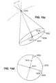
- a “navigational” viewcan be determined according to two points in an image, such as an entry point at the surface of a body and a target point within the body. The line joining the entry point and the target point is chosen as the intersection of two orthogonal planes, navigation planes 1 and 2 .
- the orientation of navigational planes 1 and 2is arbitrary (that is, the two planes can be rotated together around their intersecting line).
- a third plane, orthogonal to navigation planes 1 and 2provides a “bird's eye”) view looking from the entry point to the target point.
- This bird's eye planeis typically chosen to pass through the target point.
- FIG. 14 auch a navigational view is shown in FIG. 14 a ).
- the orientation of a surgical instrumentis typically shown as a line projected orthogonally onto the two navigational planes, and as the point of intersection of the line and the bird's eye plane. Manipulating an instrument using such a navigational view for feedback requires considerable practice and is not intuitive for many people.
- Image-guided frameless stereotaxyhas also been applied to spine surgery.
- a reference frameis attached to an exposed spinous process during open spine surgery, and a probe is used to register the patient's spine with scanned image of the spine.
- Anatomical landmarksare used as fiducial points which are located in the scanned image.
- Visual feedbackis provided to manually guide placement of instruments, such as insertion of pedicle screws into the spinal structures.
- the inventionis a method for positioning a surgical instrument during stereotactic surgery by providing a guidance fixture that includes an upper portion, including an instrument guide for moving the surgical instrument along a constrained trajectory relative to the upper portion, and also includes an adjustable base supporting the upper portion, including a mounting base and an adjustment mechanism.
- the methodincludes attaching the guidance fixture to a body, including attaching the mounting base to the body.
- the methodalso includes determining, using a remote sensing device, the orientation of the upper portion of the guidance assembly in relation to the body, and displaying a representation of a relationship of the constrained trajectory and a target point in the body.
- the methodalso includes aligning the guidance fixture, including aligning the orientation of the upper portion to achieve a desired relation between the constrained trajectory and the target point.
- Aligning the orientation of the upper portionincludes rotating the upper portion about a central axis of the mounting base and pivoting the upper portion to adjust an angle between the upper portion and the central axis.
- Determining the orientation of the upper portionincludes determining the locations of a first set of tracking markers affixed to the upper portion, determining the locations of a second set of tracking markers affixed to the body, and computing the orientation using the locations of the first and the second sets of tracking markers.
- Aligning the orientation of the upper portioncan include rotating the upper portion about a central axis of the mounting base, and pivoting the upper portion to adjust an angle between the upper portion and the central axis.
- Displaying the representation of the relationship of the constrained trajectory and the target pointthen includes displaying a representation of the target point, displaying a representation of the range of possible orientations of the guidance fixture, displaying a first line segment corresponding to possible orientations of the guidance fixture that could result from pivoting the upper portion at a current degree of rotation of the upper portion, and displaying an indication of a current degree of pivoting of the upper portion.
- the inventionis a guidance fixture for guiding a surgical instrument into a body during stereotactic surgery.
- the fixtureincludes an upper portion including an instrument guide for moving the surgical instrument along a constrained trajectory relative to the upper portion, and an adjustable base supporting the upper portion, including a mounting base for attaching the guidance fixture to a body, the mounting base having central opening and a central axis passing through the central opening, and an orientation adjustment mechanism coupled between the mounting base and the upper portion, configuration of the adjustment mechanism determine the orientation of the upper portion relative to the mounting base.
- the guidance fixturecan include a set of tracking markers, such as light emitting diodes, that can be located by a remote sensing device, such as an array of camera.
- the orientation adjustment mechanism of the guidance fixturecan include a rotation adjustment mechanism and a pivoting adjustment mechanism, wherein adjustment of the rotation adjustment mechanism rotates the upper portion about the central axis, and adjustment of the pivoting adjustment mechanism adjusts an angle between the upper portion and the central axis.
- the rotation adjustment mechanismcan include a rotating collar attached to the mounting base and the pivoting adjustment mechanism includes a pivoting collar coupling the rotating collar to the upper portion.
- the adjustable basecan further include a rotation locking screw for preventing rotation of the rotating collar and a pivoting locking screw for preventing pivoting of the pivoting collar.
- the upper portion of the guidance fixturecan include an x-y table adjustment of which displaces the constrained trajectory.
- the instrument guide of the guidance fixturecan include a driving mechanism for positioning the instrument along the constrained trajectory, such as a linear trajectory.
- the inventionis a system for stereotactic surgery on a body, which includes a remote sensing device, a tracking frame, including a plurality of tracking markers for tracking a location and an orientation of the body by the remote sensing device, and a guidance fixture.
- the systemalso includes a tracking system for accepting the locations of the tracking markers on the tracking frame and the locations of the tracking markers on the guidance fixture, and computing a relationship between the constrained trajectory and the body, and a display system for presenting an image of the body and the relationship between the constrained trajectory and the body.
- An additional advantageis that the invention does not require immobilizing (i.e., clamping in a fixed position) the patient. This contributes to patient comfort which can extend the time a surgical procedure can be carried out. Furthermore, since a guidance fixture is not attached until a scan has been made, surgical time is further extended as discomfort generally relates to having a guidance fixture attached. Also, alignment of the guidance fixture is made easier with this invention, and therefore, less time can be spent on alignment, thereby leaving more time for the actual surgical procedure.
- Another advantage of the inventionis that alignment of the guidance fixture is performed using motions, each of which is constrained to one degree of freedom (e.g., rotation or pivoting).
- this arrangementprovides a relatively stable alignment compared to alternative arrangements in which a two degree of freedom motion (such as alignment of a ball and socket arrangement) is clamped.
- Yet another advantage of the inventionis that the constrained motions of the guidance fixture, that is, the rotation and pivoting motions, are directly reflected in the computer displayed navigational view, thereby greatly simplifying targeting.
- FIG. 1is a flowchart of a stereotactic brain surgery procedure
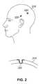
- FIG. 2is a head with threaded inserts implanted including a cross-sectional view of the skull and a threaded insert;
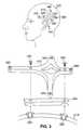
- FIG. 3is a head with a scanning MIRRF attached including a detailed exploded view of the attachment of the MIRRF to the implanted threaded inserts;
- FIG. 4illustrates scanning of a head on which a scanning MIRRF is attached
- FIG. 5is a head with a tracking MIRRF attached and a cranial probe being tracked using a camera array;
- FIG. 6is a dataflow diagram for computation of a composite image including a synthesized image of a probe
- FIG. 7illustrates locating a planned entry point using the tracked cranial probe and a computer display
- FIG. 8is a display of a virtual burr hole and accessible cone of orientations
- FIG. 9is a head with a tracking MIRRF and a guidance fixture attached being tracked using a camera array
- FIG. 10is a view of a base platter and an adjustable base of a guidance fixture
- FIG. 11is an exploded view of the adjustable base of a guidance fixture
- FIG. 12is a dataflow diagram for computation of a composite image including a synthesized image of a surgical instrument
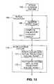
- FIG. 13is a detailed flowchart of trajectory replanning and fixture alignment
- FIGS. 14 a-cillustrate a navigational view display and corresponding planar segments through a body
- FIGS. 15 a-fillustrate a “field of view” display and corresponding conical section through a body
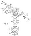
- FIG. 16is a guidance fixture including an adjustable base and an instrument drive attached to a base platter;
- FIG. 17is a retractor in a guidance fixture
- FIG. 18is a calibration jig
- FIG. 19is a phantom jig and a guidance fixture and a tracking MIRRF attached to the jig;
- FIG. 20is an arc shaped MIRRF attached to a head including a view of a threaded insert and mounting bolt;
- FIG. 21is a scanning marker and a tracking marker attached to a threaded insert
- FIG. 22is a guidance fixture and a tracking MIRRF attached to a conventional stereotactic frame.
- FIG. 23is a tracking MIRRF attached directly to a guidance fixture.
- an aspect of the inventionrelates to stereotactic brain surgery.
- This approach to brain surgeryinvolves a series of steps, shown in FIG. 1, from start 100 prior to scanning through finish 199 after the surgical phase of a procedure is completed.
- the first phaseinvolves creating a three-dimensional image of the head (steps 105 , 110 , 115 , 120 ), planning a surgical trajectory based on the image (step 125 ), and validating the guidance fixture (step 130 ) that will be used during the surgical procedure.
- the second phaseinvolves the remaining steps (steps 135 through 195 ) that are used to carry out the actual surgical procedure.
- the steps of the first phasecan be carried out quite some time before those of the second phase.
- creating the three-dimensional image of the headcan be done on one day, and the steps used to carry out the actual surgery can be done on a subsequent day.
- the steps of the second phasemay be repeated, for example on several different days, illustrated by transition 192 between steps 195 and 135 .
- the first step of the procedureis to attach anchors to which scanning, registration, and tracking markers will be subsequently attached (step 105 ).
- the anchorsinclude two threaded inserts 220 that are surgically implanted into the patient's skull 210 using a template (described below).
- the templateprecisely determines the separation and parallel orientation of inserts 220 .
- a rigid cross-shaped devicea scanning “miniature removable reference frame” (scanning MIRRF) 310 , is next attached to threaded inserts 220 using screws 320 (FIG. 1, step 110 ).
- a retention plate 330is used to aid precise reattachment of scanning MIRRF 310 to the skull. Retention plate 330 is also used as the template during insertion of threaded inserts 220 .
- Scanning MIRRF 310includes four fiducial scanning markers 340 that will be visible in the scanned image. Scanning MIRRF 310 is made from a material that is chosen to interfere as little as possible with the type of scan that will be performed.
- MRI or CT scanner 400is used to obtain a three-dimensional digitized image 410 of the head, for example, as a series of two-dimensional “slices” (step 115 in FIG. 1 ).
- a model or map of the surface of the skullcan be made allowing, for instance, subsequent three-dimensional surface display of the skull.
- the fiducial scanning markers 340produce fiducial images 420 at in image 410 .
- Fiducial coordinates 421 of fiducial images 420 in the coordinate system of image 410are determined, for example, by manually positioning a cursor at fiducial images 420 on a computer display.
- Image 410along with the fiducial coordinates 421 , are stored on a computer readable storage medium 430 for use during the subsequent surgical phase of the approach.
- imageis stored as a series of two-dimensional images, each corresponding to a horizontal “slice” of the head.
- scanning MIRRF 310is removed (FIG. 1, step 120 ), and threaded inserts 220 are left in place.
- Antibiotic ointmentcan be applied and the patient is either discharged or sent to the operating room.
- a surgeondetermines the location of a target point within the brain and an entry point through the skull (FIG. 1, step 125 ).
- a planned surgical trajectoryis then determined as the line joining the entry point and the target point.
- the surgeonplans the trajectory using a computer display of image 410 which provides, for example, a three-dimensional surface view, and sagittal, coronal, and axial planar views. This allows the surgeon, for example, to plan a trajectory that avoids critical structures in the brain.
- the target and entry points, and the trajectoryare stored along with the image on storage medium 430 .
- the surgical phase of the procedurebegins by attaching a tracking MIRRF 510 to threaded inserts 220 (not shown) that remained implanted in the patient's skull after scanning MIRRF 310 was previously removed.
- Tracking MIRRF 510has a very similar structure to scanning MIRRF 310 .
- Tracking MIRRF 510includes fiducial divots 540 at the centers of locations corresponding to fiducial markers 340 (shown in FIGS. 3 and 4 ).
- Four tracking LEDs 550are also attached to tracking MIRRF 510 .
- tracking MIRRF 510is rigid, the geometric relationship between tracking LEDs 550 and fiducial divots 540 is fixed and can be determined beforehand and verified in a subsequent verification step, or can be unknown and determined in a subsequent registration step.
- tracking MIRRF 510is made of a material that is lightweight and can be autoclaved, such as Radel.
- the patientAfter attaching tracking MIRRF 510 to the patient's skull, the patient can be comfortably placed in an awake, possibly lightly sedated, state in an operating room chair, which is similar to a dental chair. The patient is allowed to recline in an essentially unrestrained manner in the operating room chair in a semi-sitting position. Alternatively, at the surgeon's prerogative and if appropriate, general anesthesia can be administered to the patient.
- a camera array 560provides time-varying digitized images 586 to a localization application 588 executing on a computer workstation 580 .
- the patientcan be free to move relative to camera array 560 and relative to the operating room chair, and camera array 560 can be free to move relative to the patient and relative to the operating room chair.
- Camera array 560includes three CCD cameras 562 positioned in a fixed configuration relative to one another. Alternatively, two cameras, which are sufficient for three dimensional localization, or more than three cameras, which may provide greater accuracy, can be used. Each camera 562 in camera array 560 produces one time-varying image.
- Each tracking LED 550 on tracking MIRRF 510is powered and emits infra-red illumination which is seen as a bright point in each of time-varying digitized images 586 .
- localization application 588Based on the relative coordinates of the bright points in images 586 from each camera 562 of camera array 560 localization application 588 computes the position (i.e., the coordinates) of tracking LEDs 550 in the coordinate system of camera array 560 .
- the location and orientation of tracking MIRRF 510can be computed by localization application 588 . Tracking of MIRRF coordinates 510 is illustrated schematically by line 564 .
- a cranial probe 570including three probe LEDs 572 attached along its length, is also tracked using camera array 560 and localization application 588 . Based on the coordinates of the images of probe LEDs 572 in images 586 and probe geometry 584 , localization application 588 computes the position and orientation of probe 570 in the coordinate system of camera array 560 .
- the coordinates of the fiducial divotscan be computed from the coordinates of the tracking LEDs, which in turn can be computed from the locations of the fiducial images in the camera images.
- the step of touching the divotscan be omitted in this case, or used to verify the computed coordinates of fiducial divots.
- localization application 588continuously combines image 410 and a synthesized image of probe 570 to form a composite image 599 that combines the scanned image with the synthesized image of the probe.
- Composite image 599is shown on a computer display 610 which includes a three-dimensional surface display.
- the registration and image composition functions performed by localization application 588involves a series of data processing stages. As shown in FIG. 5, time-varying digitized images 586 are provided to localization application 588 from camera array 560 . Referring to FIG. 6, time-varying digitized images 586 are input to MIRRF tracking 591 , a processing stage of localization application 588 , which tracks tracking LEDs 550 on tracking MIRRF 510 and produces “MIRRF/cam” 593 , an orientation and location of tracking MIRRF 510 in the coordinate system of camera array 560 . At the same time, probe tracking 590 tracks probe 570 and produces “probe/cam” 592 , an orientation and location of probe 570 in the coordinate system of camera array 560 .
- Probe tracking 590makes use of probe geometry 584 which specifies the geometric relationship between the tip of the probe 570 and probe LEDs 572 .
- the next stage of localization application 588relative positioning 594 inputs MIRRF/cam 593 and probe/cam 592 and produces “probe/MIRRF” 595 , the position and orientation of probe 570 in the coordinate system of tracking MIRRF 510 .
- registration 581takes the location information from probe/MIRRF 595 and records it in “fids/MIRRF” 582 , the coordinates of fiducial divots 540 in the coordinate system of tracking MIRRF 510 .
- Fiducial coordinates 421the coordinates of fiducial images 420 in the coordinate system of image 410 , are provided to localization application 588 , along with image 410 , from storage medium 430 .
- Mapping 587includes matching of corresponding coordinates in fids/MIRRF 582 and fiducial coordinates 421 and forming a conformal map 589 between the coordinate system of image 410 and the coordinate system of tracking MIRRF 510 .
- Conformal map 589includes the quantities required to transform any three-dimensional coordinate in the coordinate system of tracking MIRRF 510 into a three-dimensional coordinate in the coordinate system of image 410 . These quantities correspond, in general, to a rotation, scaling, and translation of points in the coordinate system of tracking MIRRF 510 to determine the corresponding points in the coordinate system of image 410 .
- probe mapping 596takes the continually updated probe coordinates, probe/MIRRF 595 , and conformal map 589 , and computes probe/image 597 , the coordinates of probe 570 in the coordinate system of image 410 . Then, image composition 598 combines image 410 and a synthesized image of probe 570 to form composite image 599 .
- Composite image 599typically includes a three-dimensional surface view and three orthogonal planar views.
- the orthogonal planar viewscan correspond to the three standard orientations, sagittal, coronal, and axial planes, for instance passing through the planned target point. More typically, three planar views of a navigational view that is determined by the planned entry and target points are included in composite image 599 .
- the tip of the probeis displayed as an orthogonal projection onto the planes of the planar views, and as a point in an appropriate geometric relationship in the three-dimensional surface view.
- the orientation of the probecan be displayed using a line passing through the tip of the probe and displayed as a orthogonal projection onto navigational planes 1 and 2 of the navigational view, and as a point of intersection on the bird's eye view of the navigational view.
- fiducial divots 540If the geometric relationships of the fiducial points, fids/MIRRF 582 , the coordinates of fiducial divots 540 does not match the geometric relationships of fiducial coordinates 421 , then an error in placing probe 570 during the registration procedure may have occurred. If such an error is detected, conformal mapping 589 is not computed, a warning is provided to the surgeon, and the surgeon must perform the registration procedure again. Furthermore, if the geometric relationships between fiducial divots 540 is known through prior measurement or calibration, registration errors and errors locating fiducial points 420 in image 410 can also be detected.
- a cranial probe 570is used to determine an actual entry point.
- a computer display 610shows composite image 599 , which includes a three-dimensional surface view and three planar views of a navigational view determined by the planned entry and target points.
- a virtual burr hole 640is displayed in the planar views of navigational view at the probe location 642 of cranial probe 570 .
- the range of adjustable orientations of a guidance fixture that would be attached at probe location 642is displayed as a cone 644
- the extent of effects of x-y adjustment of the guidance fixtureis displayed as a second cone 646 . Display of cones 644 and 646 allows the surgeon to verify that planned target point 650 is accessible in the range of adjustments of a guidance fixture attached at probe location 642 .
- the entry pointWhen the surgeon has located an entry point 620 on the skull, he marks the entry point as the desired center point of attachment of a guidance fixture that will be used during the surgical phase of the procedure.
- the patientthen has a small area of the head shaved and draped off.
- a 2 to 4 cm linear incisionis made over entry point 620 after local anesthesia is administered.
- the location of entry point 620is then reconfirmed using cranial probe 570 after the incision is made.
- An approximately 1 cm burr hole(not shown in FIG. 7) is then drilled through the skull at entry point 620 (FIG. 1, step 150 ).
- the surgeonopens the dura under the burr hole and visually inspects the area to determine that no critical structures, such as a blood vessel, are located directly under the burr hole. If the location of the burr hole is found to be unacceptable, a new entry point can be planned and return to the step of locating the entry point (FIG. 1, step 145 ).
- a surgical instrument 740including an instrument LED 742 fixed relative to the instrument, passes through guidance fixture 710 .
- Surgical instrument 740is constrained to follow a fixed trajectory perpendicular to and through a central opening through adjusted base platter 720 .
- Workstation 580tracks the location and orientation of base platter 720 , and the displacement of surgical instrument 740 , indicated schematically by lines 564 and 750 respectively, and computes the position of surgical instrument 740 in the coordinate system of image 410 .
- Workstation 580continually displays on display 610 a composite image 750 including a navigational view of image 410 showing the position and orientation of surgical instrument 740 .
- the surgeonuses the visual feedback on display 610 to position surgical instrument 740 along the constrained trajectory.
- both the patient and camera array 560can move and, as long as platter LEDs 730 and instrument LED 742 are visible to camera array 560 at an appropriate distance and orientation, workstation 580 can maintain a continuously updated display.
- guidance fixture 710includes base platter 720 and adjustable base 715 .
- base platter 720is attached to an entry column 850 (through an x-y positioning table 1150 , described fully below) which is held in adjustable base 715 .
- the orientation of entry column 850can be adjusted relative to skull 210 using separate rotation and pivoting motions, as described below.
- guidance base 715includes a mounting base 820 , which is rigidly attached to the skull during an operation using screws through mounting holes 822 .
- Mounting holes 822pass through mounting tabs 723 as well as through the inside of the mounting base 820 .
- Mounting tabs 823are pliable to allow them to conform to the skull.
- mounting base 820may be distorted in being mounted to the skull, it can be designed to be disposable.
- Mounting base 820has a cylindrical opening which accepts a rotating collar 830 .
- a rotation locking screw 824 in mounting base 820when tightened, locks rotating collar 830 in place and prevents its movement within the mounting base.
- Entry column 850is held within rotating collar 830 by a pivoting collar 840 .
- Pivoting collar 840slides in an arc-shaped pivoting guide 841 within rotating collar 830 .
- a pivoting locking knob 846prevents pivoting collar 840 from sliding by drawing a collar clamp 842 against pivoting collar 840 using a threaded rod 920 .
- a pivoting adjustment knob 844slides pivoting collar 840 along pivoting guide 841 .
- mounting base 820includes mounting holes 822 drilled through mounting tabs 723 (one tab is not visible on the side opposite the visible one), as well as through the inside of mounting base 820 .
- Mounting base 820includes a threaded hole 922 within which rotation locking screw 824 turns. Rotation locking screw 824 mates with a recessed channel 923 in rotating collar 830 , thereby preventing rotation of rotating collar 830 and also preventing rotating collar 830 from lifting off mounting base 820 .
- Entry column 850includes a cylindrical portion 913 and a spherical portion 914 at one end. Spherical portion 914 mates with a spherical socket 916 in the bottom of rotating collar 830 . When mated, entry column 850 can pivot within rotating collar 830 . Entry column 850 also has opposing groves 910 which mate with protrusions 912 on the inside of the circular opening in pivoting collar 840 . Entry column 850 passes through the circular opening, and protrusions 912 mate with groves 910 . When assembled, the mated groves and protrusions hold the spherical portion 914 of entry column 850 against spherical socket 916 in the bottom of rotating collar 830 .
- pivoting collar 840within pivoting guide 841 is adjusted by turning pivoting adjustment knob 844 and tightened in place by rotating pivoting tightening knob 846 .
- Pivoting adjustment knob 844attaches to a pivoting adjustment rod 930 which passes through collar clamp 842 and the main portion of pivoting collar 840 to a rack and pinion mechanism.
- a pinion 931is attached to the end pivoting adjustment rod 930 .
- Pinion 931mates with an arc-shaped rack 932 which attaches to rotating collar 830 using three screws 934 .
- Rotation of pivoting adjustment knob 844rotates pivoting adjustment rod 930 and pinion 931 , which then slides pivoting collar 840 in pivoting guide 841 .
- Rotating pivoting locking knob 846locks pivoting collar 840 rigidly to rotating collar 830 . Tightening both rotation locking screw 824 and pivoting locking knob 846 fixes the orientation of entry column 850 relative to mounting base 820 .
- the procedure for attaching and adjusting guidance fixture 710(FIG. 1, steps 155 through 170 ) is carried out as follows.
- Mounting base 820is attached in a temporary fashion over burr hole 625 . While attaching the base, mounting tabs 723 are conformed to the shape of the skull 210 and secured to the skull an orientation generally directed towards the target using three or more titanium bone screws 724 passing through mounting holes 822 through mounting tabs 723 and through the interior of the mounting base.
- guidance base 715is attached to skull 210 , the remainder of guidance fixture 710 is attached to guidance base 715 .
- the drive assemblywhich is already attached to base platter 720 at the time base platter 720 is attached to guidance base 715 is not shown.
- Base platter 720is attached to entry column 850 via an x-y positioning table 1150 (described below). During the alignment phase in which the orientation of guidance base 715 is adjusted, x-y positioning table 1150 remains centered.
- surgical instrument 740is passed through a central opening 721 of base platter 720 and through entry column 850 into the brain.
- a line along the trajectory surgical instrument 740would follow passes along the central axis of entry column 850 .
- Adjusting the orientation of guidance base 715adjusts this trajectory. In all orientations, the trajectory passes through a single point on the central axis of guidance base 715 near the surface of the skull. If the guidance base is exactly mounted over the planned entry point, this single point is the planned entry point. More typically, the point is slightly displaced from the planned entry point due to mounting inaccuracies.
- platter LEDs 730 on base platter 720are sensed by camera array 560 , and the location and orientation of base platter 720 in the coordinate system of image 410 is computed by localization application 588 executing on computer workstation 580 .
- Localization application 588computes the location and orientation of base platter 720 using the known geometry of the base platter relative to platter LEDs 730 .
- localization application 588computes composite image 750 (FIG. 9) in a series of data transformations.
- Time-varying digitized images 586are passed to MIRRF tracking 591 as well as platter tracking 7010 and instrument tracking 7012 .
- MIRRF tracking 591produces “MIRRF/cam” 592 , the position and orientation of tracking MIRRF 510 in the coordinate system of camera array 560 .
- Platter tracking 7010produces “platter/cam” 7020 , the position and orientation of base platter 720 .
- the instrument trajectoryis at a known location and orientation relative to platter LEDs 730 on base platter 720 , therefore the location and orientation of the instrument trajectory in the coordinate system of camera array 560 is also known.
- Instrument tracking 7012produces instrument/cam 7022 , the location of instrument LED 742 in the coordinate system of camera array 560 .
- Platter localization 7030uses conformal map 589 , MIRRF/cam 593 , and platter/cam 7020 to compute platter/image 7040 , the location and orientation of base platter 720 in the coordinate system of image 410 . Note that once guidance fixture 710 is attached and aligned, then base platter 720 no longer moves relative to the skull (other than due to adjustment of x-y table 1150 ) and therefore, platter/image 7040 can be fixed rather than continuously recomputed.
- Instrument depth measurement 7032combines platter/cam 7020 and instrument/cam 7022 to compute instrument/platter 7042 , the depth of penetration of the surgical instrument relative to the plane of base platter 720 .
- Instrument depth measurement 7032makes use of the known displacement of the tip of the instrument from instrument LED 742 .
- Instrument localization 7050takes platter/image 7040 and instrument/platter 7042 and computes instrument/image 7060 , the location and orientation of the surgical instrument in the coordinate system of image 410 .
- image composition 7070combines image 410 with a synthesized image of the surgical instrument to generate a composite image 750 .
- the surgical trajectoryis optionally replanned to go through the center of the actual mounted position of the guidance fixture, rather than the planned entry point (FIG. 1, step 165 ).
- FIGS. 14 a-ca navigational view indicating the trajectory of the surgical instrument is used.
- navigational planes 1020 and 1022correspond to navigational planar views 1030 and 1032 respectively.
- Navigational planes 1020 and 1022are orthogonal and their intersection forms a line passing through an entry point 1010 and a target point 1012 .
- Bird's eye plane 1024the third plane of the navigational view, is orthogonal to planes 1020 and 1024 and passes through target point 1012 .
- navigational planes 1020 and 1024are shown schematically, along with a line 1040 corresponding to the orientation of guidance fixture 710 .
- the goal of the alignment procedureis to make line 1040 coincident with the intersection of planes 1020 and 1022 .
- the alignment procedureis carried out in a series of two motions each of which is constrained to one degree of freedom. Initially, line 1040 is not generally coincident with either navigational plane.
- the orientation of line 1040is displayed as orthogonal projections, lines 1041 and 1042 , on planes 1020 and 1022 , respectively.
- rotating collar 830is rotated within mounting base 820 (FIGS. 10 and 11 ). Referring to FIG. 14 b, this rotation causes line 1040 to sweep out a portion of a cone, indicated diagrammatically by dashed arrow 1050 .
- orientation line 1040is in the direction of line 1043 , which is coincident with plane 1022 .
- the orthogonal projection line 1041 of line 1040 in plane 1020forms a smaller and smaller angle è 1 with the desired orientation in plane 1020
- the angle è 2 between the orthogonal projection line 1042 in plane 1022 and the desired orientation in plane 1022increases, ultimately to ö 2 when line 1040 is coincident with plane 1022 .
- the second alignment motionreduces the angle ö 2 while maintaining the coincidence of the orientation line and plane 1022 .
- This motioncorresponds to sliding pivoting collar 840 within rotating collar 830 (FIGS. 8 and 9 ). Alignment is achieved when angle ö 2 is zero, that is, the orientation line 1040 is coincident with the intersection of planes 1020 and 1022 .
- base platter 720is firmly fixed to the skull, in an orientation and location that constrains a surgical instrument passing through it to pass along the replanned trajectory to the planned target point in the head.
- a “field of view” displaycan be provided.
- the field of view displayuses a representation of a cross-section of a cone extending below the entry point.
- the central axis of a cone 1061is coincident with the central axis of the mounting base of a guidance fixture mounted at an entry point 1010 . That is, the central axis of the cone is generally perpendicular to the surface of the skull at the entry point.
- the angle of the conecorresponds to the range of possible alignments of a guidance fixture mounted at the entry point. In this embodiment, this is a 45 degree angle.
- the cross-sectionis normal to the central axis of the cone, and passes through a target point 1012 .
- the corresponding displayshows a circular section 1070 of the scanned image.
- the center 1011 and the target point 1012are indicated.
- Also indicatedare two orthogonal axes.
- An axis 1072corresponds to the achievable orientations of the guidance fixture as its pivoting collar is moved in the rotating collar.
- Another axis 1074is orthogonal to axis 1072 . Motion of the rotating collar rotates the orientation of axes 1072 and 1074 .
- FIG. 15 cshows the display after this rotation.
- Motion of the pivoting collaris indicated by a line 1076 , parallel to axis 1074 . If the pivoting collar is centered, then line 1076 is aligned with axis 1074 , as is shown in FIG. 15 d.
- FIG. 15 fshows the display after alignment is achieved.
- This circular field of view displayprovides intuitive visual feedback to the surgeon who is aligning the guidance fixture.
- displacement of the x-y tablecan also be shown in such a field of view display, by indicating the intersection of the resulting instrument trajectory on the circular display.
- an instrument drive 1110is attached to base platter 720 prior to attaching the combination of instrument drive 1110 , base platter 720 , and x-y table 1150 to guidance base 715 .
- instrument drive 1110is shown partially mounted onto a drive post 1120 .
- drive post 1120Prior to attachment to guidance base 715 , drive post 1120 is fully inserted into instrument drive 1110 so that instrument drive 1110 is in contact with base platter 720 .
- Base platter 720can be displaced relative to guidance base 715 in a plane orthogonal to entry column 850 using two perpendicular adjustment screws 1060 , and 1062 turned by x-y table adjustment knobs 1061 , and 1063 . Note that prior to alignment (FIG. 1, step 170 ) the x-y table is adjusted so that central opening 721 in base platter 720 is centered over entry column 850 .
- Instrument drive 1110includes a drive platform 1130 that moves within a drive mechanism 1125 along a threaded rod 1132 .
- Threaded rod 1132is oriented parallel to drive post 1120 and perpendicular to base platter 720 .
- rotation of threaded rod 1132which causes displacement of drive platform 1130 , is manual using a mechanism that is not shown.
- Alternative embodimentscan use an electronic stepper motor or a manual hydraulic drive to rotate threaded rod 1132 and thereby displace drive platform 1130 .
- a surgical instrumentsuch as a micro-electrode
- a guidance tubeAfter alignment of guidance fixture 710 , the guidance tube is manually inserted into the brain through central opening 721 in base platter 720 . The guidance tube is then secured in clamp 1135 that is fixed relative to drive mechanism 1125 . The instrument is passed into the guidance tube and is secured in a clamp 1133 , which is fixed relative to drive platform 1130 .
- Instrument LED 742is attached to drive platform 1130 .
- the displacement of the end of the surgical instrument from instrument LED 742is known to localization application 588 which executes on workstation 580 .
- localization application 588executes on workstation 580 .
- the position of instrument LED 742 , as well as platter LEDs 730the position of the end of a surgical instrument on workstation 580 and displayed on display 610 (FIG. 9) to the surgeon. The surgeon then uses this visual feedback in adjusting the depth of the instrument.
- Various types of surgical probes or instrumentscan be attached to drive mechanism 1110 shown in FIG. 16 .
- One type of instrumentis an electrode, such as a recording micro-electrode or a stimulating electrode or lesioning electrode. The electrode is introduced into a rigid insertion (guidance) tube that is attached to drive mechanism 1110 .
- Another type of instrumentis a hypothermia cold probe.
- a chronically implanted stimulating electrodecan be placed utilizing an insertion tube.
- the leadbeing of a smaller diameter than the insertion tube, can be slipped through the insertion tube upon removal of the drive and guide assembly, to allow fixation of the chronically implanted electrode into the brain.
- the electrodeis secured to the skull using a compression-fitting.
- a chronically implanted recording electrodecan similarly be placed during epilepsy surgery to monitor abnormal activity within the deep brain utilizing similar techniques.
- a shunt tubesuch as a ventricular shunt
- the shunt tubewill have a stylet and be slipped into the insertion tube.
- the insertion tube structure and its retention ringwill have varying diameters, depending on the diameters of the various objects that can be placed in the insertion tube, such as the shunt tube, in this application, or micro-electrodes, in the prior application.
- the insertion tubetherefore, will be connected to the drive mechanism using varying sized retention rings.
- the shuntwill be directed is towards the target established by the software mechanism alluded to above.
- the shunt tubewill then be secured to the skull via mechanisms described in prior art, or via a compression fitting described above.
- a biopsy probecan be inserted into the insertion tube by first placing a biopsy tube with a trocar/obturator through the insertion tube. The mechanism would then be directed down towards the appropriate target using the drive mechanism. The obturator would be removed, and a cutting blade will then be inserted into the biopsy tube.
- a different insertion tubecan be connected to the drive mechanism 1110 .
- a delivery cathetercan be placed through the insertion tube. The whole mechanism can be directed towards the deep target using the software system as alluded to above.
- An insertion plungercan be used to insert the object of delivery and the system is then be removed after insertion of the object.
- a micro-endoscopecan also be inserted through the insertion tube mechanism described above and deep brain structures can be visualized prior to excision or lesioning.
- An example of a procedure using penetration of an instrument along parallel tracksinvolves mapping the electrical activity of a region of the brain.
- the surgical instrumentin this case is a thin electrode that is repeatedly inserted to points on a two- or three-dimensional grid. At each point, electrical activity is monitored.
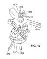
- the drive mechanismhas a localizing surgical retractor 1210 mounted in place of the insertion tube, and base platter 1220 has a large central opening through which the retractor passes.
- Retractor 1210includes three or more spatulas 1212 inserted through base platter 1220 and the entry column. Each spatula 1212 includes a tracking LED 1214 attached to it.
- the relationship of the spatulasis controlled by a screw assembly 1216 that allows the relative distance between the spatulas to be modified. Relatively small movement at the screw assembly results in a larger movement at the other ends of the spatulas due to the pivoting of the spatulas within the retractor.
- Tracking LEDs 1214are tracked by the camera array and the localization application computes the depth of spatulas 1212 and their displacement from the central axis.
- surgical localizing retractor 1210is directed towards the brain target.
- screw assembly 1216is adjusted to expand localizing retractor 1210 to allow visualization of the underlying brain.
- a variety of surgical instrumentscan be attached to retractor 1210 in addition to using the retractor with more conventional manual techniques. These instruments can include an endoscope, an ultrasonic aspirator, an electronic coagulation/evaporator/ablator, or a laser.
- An optional fixture validation step(FIG. 1, step 130 ) can be used to confirm that the position of the tip of the surgical instrument is accurately tracked.
- Two types of validationcan be performed. Referring to FIG. 18, guidance fixture 710 is attached to an upper mounting plate 1334 of a calibration jig 1330 . Prior to attaching guidance fixture 710 to calibration jig 1330 , pivoting locking knob 846 (FIG. 10) is loosened allowing pivoting collar 840 to pivot. After guidance fixture 710 is attached, pivoting collar 840 is centered and pivoting locking knob 846 is tightened.
- a guidance tube 1340is clamped into the guidance fixture, and a surgical instrument 1342 is passed through the guidance tube.
- Guidance tube 1340protrudes below upper mounting plate 1334 .
- a ruler 1335can then be used to measure the depth of penetration of the guidance tube. Similarly, ruler 1335 can be used to measure the penetration of surgical instrument 1342 .
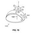
- a validation (or “phantom”) jig 1312can also be used.
- Tracking MIRRF 510is attached to validation jig 1312 .
- Guidance fixture 710is be mounted on validation jig 1312 .
- a phantom target point 1320 at a known position relative to validation jig 1312 , and therefore at a known position relative to the fiducial points on tracking MIRRF 510is chosen.
- the localization application 588is programmed with the phantom target position. Using the procedure that will be used during the surgical phase, the surgeon performs the registration and alignment steps and then drives the instrument through guidance fixture 710 .
- guidance fixture 710is validated. If for some reason the instrument is not coincident with the phantom target point, for example, due to improper attachment of the instrument to the drive assembly resulting in an incorrect depth calibration, the surgeon readjusts the instrument and attempts the validation step again.
- scanning MIRRF 310 and tracking MIRRF 510are star-shaped. Other alternative shapes of MIRRFs can be used.
- an arc-shaped MIRRF 1410is attached to threaded inserts 1420 using bolts 1430 , and marking and locking nuts 1432 .
- Arc-shaped MIRRF 1410includes scanning fiducial markers 1412 . The fiducial markers are more widely spaced than in star-shaped MIRRFs 310 , and 510 , resulting in a more accurate tracing of the MIRRF.
- arc-shaped MIRRF 1410acts as a template for accurate positioning of the threaded inserts.
- threaded insertsare inserted into the skull to provide the fixed points of attachment for MIRRFs.
- Alternative embodimentsuse other types of anchors or forms of mechanical attachment.
- Protruding postscan be attached to the skull.
- a MIRRFis then attached to the posts.
- insertscan be implanted in the skull which provide precisely positioned “divots.” These divots are used to mate clamping posts on a MIRRF, which hold the MIRRF in place. Such implanted divots can be covered by the skin and remain in place for an extended period of time.
- each such anchorshown as threaded insert 1440 , can support a single scanning marker 1444 on a post 1442 , subsequently support a single registration divot 1450 on a second post 1451 , and then support a single tracking marker, LED 1448 , on a third post 1446 .
- the geometric relationship of the anchor to the scanning markeris the same as the geometric relationship of the anchor to the tracking marker thereby allowing a localization application to directly track the fiducial points by tracking the location of the tracking marker.
- multiple MIRRFscan be used to provide increased accuracy in registration and tracking.
- two star-shaped MIRRFscan be used, one on each side of the head.
- the mounting basecan be relatively small and have extended “legs” extending radically and secured to the skin or skull with sharp points. These legs provide stabilization that may not be achievable using mounting screws through the smaller mounting base.
- the mounting basecan alternatively include an insert that fits into the burr hole. This insert can also be threaded to allow direct attachment of the mounting base to the burr hole.
- threaded insertsare used to attach, and subsequently accurately reattach, conventional stereotactic frames. This allows the conventional stereotactic frame to be removed and then accurately reattached to the skull. Procedures, such as fractionated multi-day stereotactic radiation treatments could then be performed with the stereotactic frame being reattached for each treatment.
- a modified guidance fixture 1510is used in combination with a conventional stereotactic frame 1520 .
- Guidance fixture 1510includes an x-y positioning table with LEDs 1512 and an instrument drive with an LED 1514 for tracking the depth of the surgical instrument.
- the guidance assemblyis positioned on frame 1520 to align with the planned surgical trajectory.
- a tracking MIRRF 1530is attached to frame 1520 to allow dynamic tracking.
- alternative embodimentscan use other features for registration.
- paste-on scanning markersare attached to the skin.
- the cranial probeis positioned at each of the paste-on markers in turn, rather than at the fiducial points on a MIRRF.
- Tracking LEDsare attached in a fixed position relative to the skull in some other way than using a MIRRF, for example, using an elastic headband.
- another alternative embodimentuses accessible anatomical features. These features are located in the scanned image, and the probe is positioned at these features during the registration phase.
- Still another alternativedoes not use discrete fiducial points, but rather makes use of the surface shape of the skull in a “surface merge” approach.
- the surface of the skullis located in the three-dimensional image.
- the cranial probetouches a large number of points on the skull. The locations of these points is matched to the shape of the skull to determine the conformal mapping from the physical coordinate system to the image coordinate system.
- a tracking MIRRF 1610can be attached directly to the base of a guidance fixture 710 . Tracking MIRRF 1610 is only useful for tracking after guidance fixture 710 has been attached to the skull. In this approach, registration is based on fiducial points elsewhere on the skull than tracking MIRRF 1610 .
- Locating the entry point, over which guidance fixture 710 is attachedcan be accomplished using one of a variety of alternative techniques.
- the entry pointmay be known for some standardized procedures.
- the entry pointmay be determined by registration of the skull and the three-dimensional image based on fiducial markers attached to the head, for example using adhesive pads, anatomical markers, or a “surface merge” technique as described above.
- LEDs 1620 on tracking MIRRF 1610are used to track the location of the skull, and thereby track the location of the surgical instrument.
- a reregistration step(FIG. 1, step 160 ) can be performed to determine the relative position of the fiducial points to LEDs 1620 .
- the guidance fixture 710optionally includes a feature that the various locking knobs and x-y adjustment knobs are rotated using a removable knob (or key). When not in use, this knob is stowed on the drive assembly. Whenever the removable knob is removed from its stowed position, the signal from an electrical sensor on the drive assembly that is connected to the workstation causes a warning, for example on the computer display, to be provided to the surgeon.
- Alternative related embodimentscan make use of known geometric relationships of points on various devices. For instance, the relationship between the tip of a probe and the location of tracking LEDs can be calibrated and used by a localization application to compute the location of tip using the computed location the LEDs. Similarly, the relationship between the location of fiducial points on a MIRRF and tracking LEDs can be calibrated, thereby allowing a localization application to compute the coordinates of fiducial points from the coordinates of the tracking LEDs without using the registration procedure described above.
- tracking LEDsare tracked using a camera.
- Other alternative embodimentscan use other three-dimensional sensing and tracking approaches. Rather than LEDs, other tracking markers that are active emitters of electromagnetic or mechanical energy such as electronic sparks, heat, magnetic energy, or sound can be used. Appropriate three-dimensional tracking approaches, for example, using imaging or triangulation techniques determine the three-dimensional coordinates of the emitters.
- tracking markersthat are passive reflectors or transducers of externally applied localizing energy, such as infrared light, sound, magnetism, can be used.
- the devices described abovecan be made of a variety of materials.
- One alternativeis to use a material, such as carbon fiber, which does not interfere with MRI scanning. This allows use of the devices during intraoperative MRI scanning. Also, use of hydraulic drive mechanisms rather than electrical motors avoids interference with MRI scanning.
- the patientis not necessary immobilized. It may be desirable, however, to immobilize the patient, for example by clamping the guidance fixture to an operating table, at some times during the surgery.
Landscapes
- Health & Medical Sciences (AREA)
- Surgery (AREA)
- Life Sciences & Earth Sciences (AREA)
- Engineering & Computer Science (AREA)
- Medical Informatics (AREA)
- Biomedical Technology (AREA)
- Heart & Thoracic Surgery (AREA)
- Nuclear Medicine, Radiotherapy & Molecular Imaging (AREA)
- Molecular Biology (AREA)
- Animal Behavior & Ethology (AREA)
- General Health & Medical Sciences (AREA)
- Public Health (AREA)
- Veterinary Medicine (AREA)
- Robotics (AREA)
- Oral & Maxillofacial Surgery (AREA)
- Pathology (AREA)
- Magnetic Resonance Imaging Apparatus (AREA)
Abstract
Description
Claims (32)
Priority Applications (1)
| Application Number | Priority Date | Filing Date | Title |
|---|---|---|---|
| US09/846,640US6298262B1 (en) | 1998-04-21 | 2001-05-01 | Instrument guidance for stereotactic surgery |
Applications Claiming Priority (2)
| Application Number | Priority Date | Filing Date | Title |
|---|---|---|---|
| US6365898A | 1998-04-21 | 1998-04-21 | |
| US09/846,640US6298262B1 (en) | 1998-04-21 | 2001-05-01 | Instrument guidance for stereotactic surgery |
Related Parent Applications (1)
| Application Number | Title | Priority Date | Filing Date |
|---|---|---|---|
| US6365898AContinuation | 1998-04-21 | 1998-04-21 |
Publications (2)
| Publication Number | Publication Date |
|---|---|
| US6298262B1true US6298262B1 (en) | 2001-10-02 |
| US20010027271A1 US20010027271A1 (en) | 2001-10-04 |
Family
ID=22050645
Family Applications (1)
| Application Number | Title | Priority Date | Filing Date |
|---|---|---|---|
| US09/846,640Expired - LifetimeUS6298262B1 (en) | 1998-04-21 | 2001-05-01 | Instrument guidance for stereotactic surgery |
Country Status (1)
| Country | Link |
|---|---|
| US (1) | US6298262B1 (en) |
Cited By (186)
| Publication number | Priority date | Publication date | Assignee | Title |
|---|---|---|---|---|
| US6428547B1 (en)* | 1999-11-25 | 2002-08-06 | Brainlab Ag | Detection of the shape of treatment devices |
| US20020147384A1 (en)* | 2001-04-10 | 2002-10-10 | Olympus Optical Co., Ltd. | Surgery support system and surgery support method |
| US6497134B1 (en)* | 2000-03-15 | 2002-12-24 | Image Guided Technologies, Inc. | Calibration of an instrument |
| US6529765B1 (en)* | 1998-04-21 | 2003-03-04 | Neutar L.L.C. | Instrumented and actuated guidance fixture for sterotactic surgery |
| US6572624B2 (en)* | 2000-04-13 | 2003-06-03 | Hoi Sang U | Stereotaxic detachable needle extension |
| US20030110881A1 (en)* | 2001-12-13 | 2003-06-19 | Trw Automotive Safety Systems Gmbh & Co. Kg | Steering device for a motor vehicle |
| US6585651B2 (en) | 1999-04-20 | 2003-07-01 | Synthes Ag Chur | Method and device for percutaneous determination of points associated with the surface of an organ |
| EP1330992A1 (en)* | 2002-01-23 | 2003-07-30 | Stiftung für Plastische und Aesthetische Wundheilung im Sondervermögen der DT Deutschen Stiftungstreuhend AG | Device and method for establishing the spatial position of an instrument relative to an object |
| US20040019265A1 (en)* | 2002-07-29 | 2004-01-29 | Mazzocchi Rudy A. | Fiducial marker devices, tools, and methods |
| US20040030236A1 (en)* | 2002-07-29 | 2004-02-12 | Mazzocchi Rudy A. | Fiducial marker devices, tools, and methods |
| US6694168B2 (en) | 1998-06-22 | 2004-02-17 | Synthes (U.S.A.) | Fiducial matching using fiducial implants |
| US20040064148A1 (en)* | 2001-09-14 | 2004-04-01 | Wolfgang Daum | Navigation of medical instrument |
| US6725082B2 (en) | 1999-03-17 | 2004-04-20 | Synthes U.S.A. | System and method for ligament graft placement |
| US6752812B1 (en) | 1997-05-15 | 2004-06-22 | Regent Of The University Of Minnesota | Remote actuation of trajectory guide |
| US20040147839A1 (en)* | 2002-10-25 | 2004-07-29 | Moctezuma De La Barrera Jose Luis | Flexible tracking article and method of using the same |
| US20040158259A1 (en)* | 2003-02-06 | 2004-08-12 | Mark Freas | Shunt passer or like surgical instrument configured for receiving different-sized positioning locators of image-guided surgical system |
| US6782288B2 (en) | 1998-10-08 | 2004-08-24 | Regents Of The University Of Minnesota | Method and apparatus for positioning a device in a body |
| US20040230055A1 (en)* | 2003-04-07 | 2004-11-18 | Woltermann Christopher J. | Using alkylmetal reagents for directed metalation of azaaromatics |
| US20050043735A1 (en)* | 2003-08-21 | 2005-02-24 | Osteomed L.P. | Bone anchor system |
| US20050085719A1 (en)* | 1998-07-06 | 2005-04-21 | Neutar L.L.C., A Maine Corporation | Customized surgical fixture |
| US6892090B2 (en) | 2002-08-19 | 2005-05-10 | Surgical Navigation Technologies, Inc. | Method and apparatus for virtual endoscopy |
| US6902569B2 (en) | 2000-08-17 | 2005-06-07 | Image-Guided Neurologics, Inc. | Trajectory guide with instrument immobilizer |
| US20050131426A1 (en)* | 2003-12-10 | 2005-06-16 | Moctezuma De La Barrera Jose L. | Adapter for surgical navigation trackers |
| US6920347B2 (en) | 2000-04-07 | 2005-07-19 | Surgical Navigation Technologies, Inc. | Trajectory storage apparatus and method for surgical navigation systems |
| US20050182317A1 (en)* | 2004-01-29 | 2005-08-18 | Haddad Souheil F. | Method and apparatus for locating medical devices in tissue |
| US6947786B2 (en) | 2002-02-28 | 2005-09-20 | Surgical Navigation Technologies, Inc. | Method and apparatus for perspective inversion |
| US20050251017A1 (en)* | 2004-04-23 | 2005-11-10 | Azar Fred S | System and method registered video endoscopy and virtual endoscopy |
| US20050256541A1 (en)* | 2004-04-30 | 2005-11-17 | Medtronic, Inc. | Catheter with temporary stimulation electrode |
| US6968224B2 (en) | 1999-10-28 | 2005-11-22 | Surgical Navigation Technologies, Inc. | Method of detecting organ matter shift in a patient |
| US20050288575A1 (en)* | 2003-12-10 | 2005-12-29 | De La Barrera Jose Luis M | Surgical navigation tracker, system and method |
| US6990368B2 (en) | 2002-04-04 | 2006-01-24 | Surgical Navigation Technologies, Inc. | Method and apparatus for virtual digital subtraction angiography |
| US20060036264A1 (en)* | 2004-08-06 | 2006-02-16 | Sean Selover | Rigidly guided implant placement |
| US7007699B2 (en) | 1999-10-28 | 2006-03-07 | Surgical Navigation Technologies, Inc. | Surgical sensor |
| USRE39133E1 (en) | 1997-09-24 | 2006-06-13 | Surgical Navigation Technologies, Inc. | Percutaneous registration apparatus and method for use in computer-assisted surgical navigation |
| US7085400B1 (en) | 2000-06-14 | 2006-08-01 | Surgical Navigation Technologies, Inc. | System and method for image based sensor calibration |
| US20060184014A1 (en)* | 2004-12-02 | 2006-08-17 | Manfred Pfeiler | Registration aid for medical images |
| US7130676B2 (en) | 1998-08-20 | 2006-10-31 | Sofamor Danek Holdings, Inc. | Fluoroscopic image guided orthopaedic surgery system with intraoperative registration |
| US7136696B2 (en) | 2002-04-05 | 2006-11-14 | The Cleveland Clinic Foundation | Neuron signal analysis system and method |
| US7166114B2 (en) | 2002-09-18 | 2007-01-23 | Stryker Leibinger Gmbh & Co Kg | Method and system for calibrating a surgical tool and adapter thereof |
| US7174202B2 (en) | 1992-08-14 | 2007-02-06 | British Telecommunications | Medical navigation apparatus |
| US20070055291A1 (en)* | 2004-08-06 | 2007-03-08 | Depuy Spine, Inc. | Rigidly guided implant placement with control assist |
| US7204840B2 (en) | 2000-04-07 | 2007-04-17 | Image-Guided Neurologics, Inc. | Deep organ access device and method |
| US7217276B2 (en) | 1999-04-20 | 2007-05-15 | Surgical Navigational Technologies, Inc. | Instrument guidance method and system for image guided surgery |
| US20070110776A1 (en)* | 2000-09-21 | 2007-05-17 | Elan Pharma International Ltd. | In vitro methods for evaluating the in vivo effectivness of dosage forms of microparticulate or nanoparticulate active agent compositions |
| US7277594B2 (en) | 1999-05-03 | 2007-10-02 | Ao Technology Ag | System and method for preparing an image corrected for the presence of a gravity induced distortion |
| US20070238961A1 (en)* | 2006-02-21 | 2007-10-11 | Brainlab Ag | Universal image registration interface |
| US20070280423A1 (en)* | 2006-05-31 | 2007-12-06 | Robert Schmidt | Registration by means of radiation marking elements |
| US7313430B2 (en) | 2003-08-28 | 2007-12-25 | Medtronic Navigation, Inc. | Method and apparatus for performing stereotactic surgery |
| US7366562B2 (en) | 2003-10-17 | 2008-04-29 | Medtronic Navigation, Inc. | Method and apparatus for surgical navigation |
| US7366561B2 (en) | 2000-04-07 | 2008-04-29 | Medtronic, Inc. | Robotic trajectory guide |
| EP1935365A1 (en)* | 2006-12-22 | 2008-06-25 | DePuy Products, Inc. | System for registering a bone of a patient with a computer assisted orthopaedic surgery system |
| US20080287954A1 (en)* | 2007-05-14 | 2008-11-20 | Queen's University At Kingston | Patient-specific surgical guidance tool and method of use |
| US20080306375A1 (en)* | 2007-06-07 | 2008-12-11 | Surgi-Vision, Inc. | Mri-guided medical interventional systems and methods |
| US20080312529A1 (en)* | 2007-06-15 | 2008-12-18 | Louis-Philippe Amiot | Computer-assisted surgery system and method |
| US7497863B2 (en) | 2004-12-04 | 2009-03-03 | Medtronic, Inc. | Instrument guiding stage apparatus and method for using same |
| US20090112084A1 (en)* | 2007-06-07 | 2009-04-30 | Surgi-Vision, Inc. | Mri-guided medical interventional systems and methods |
| US20090131783A1 (en)* | 2007-11-21 | 2009-05-21 | Surgi-Vision, Inc. | Methods, systems and computer program products for positioning a guidance apparatus relative to a patient |
| US7542791B2 (en) | 2003-01-30 | 2009-06-02 | Medtronic Navigation, Inc. | Method and apparatus for preplanning a surgical procedure |
| US20090177077A1 (en)* | 2007-09-24 | 2009-07-09 | Surgi-Vision, Inc. | Mri-compatible patches and methods for using the same |
| USRE40852E1 (en) | 1995-06-14 | 2009-07-14 | Medtronic Navigation, Inc. | Method and system for navigating a catheter probe |
| US7559935B2 (en) | 2003-02-20 | 2009-07-14 | Medtronic, Inc. | Target depth locators for trajectory guide for introducing an instrument |
| US7567834B2 (en) | 2004-05-03 | 2009-07-28 | Medtronic Navigation, Inc. | Method and apparatus for implantation between two vertebral bodies |
| US7570791B2 (en) | 2003-04-25 | 2009-08-04 | Medtronic Navigation, Inc. | Method and apparatus for performing 2D to 3D registration |
| US7599730B2 (en) | 2002-11-19 | 2009-10-06 | Medtronic Navigation, Inc. | Navigation system for cardiac therapies |
| US7606613B2 (en) | 1999-03-23 | 2009-10-20 | Medtronic Navigation, Inc. | Navigational guidance via computer-assisted fluoroscopic imaging |
| US7636595B2 (en) | 2004-10-28 | 2009-12-22 | Medtronic Navigation, Inc. | Method and apparatus for calibrating non-linear instruments |
| US7636596B2 (en) | 2002-12-20 | 2009-12-22 | Medtronic, Inc. | Organ access device and method |
| US7641660B2 (en) | 2004-03-08 | 2010-01-05 | Biomet Manufacturing Corporation | Method, apparatus, and system for image guided bone cutting |
| US7643867B2 (en) | 2003-02-25 | 2010-01-05 | Medtronic, Inc. | Fiducial marker devices, tools, and methods |
| US7657300B2 (en) | 1999-10-28 | 2010-02-02 | Medtronic Navigation, Inc. | Registration of human anatomy integrated for electromagnetic localization |
| US7660623B2 (en) | 2003-01-30 | 2010-02-09 | Medtronic Navigation, Inc. | Six degree of freedom alignment display for medical procedures |
| US7658879B2 (en) | 2003-02-20 | 2010-02-09 | Medtronic, Inc. | Trajectory guide with angled or patterned guide lumens or height adjustment |
| US20100081914A1 (en)* | 2008-09-26 | 2010-04-01 | Waynik Jeffrey M | Method and apparatus for positioning a guide relative to a base |
| US7697972B2 (en) | 2002-11-19 | 2010-04-13 | Medtronic Navigation, Inc. | Navigation system for cardiac therapies |
| US7704260B2 (en) | 2002-09-17 | 2010-04-27 | Medtronic, Inc. | Low profile instrument immobilizer |
| US7744606B2 (en) | 2004-12-04 | 2010-06-29 | Medtronic, Inc. | Multi-lumen instrument guide |
| US20100179564A1 (en)* | 2006-07-24 | 2010-07-15 | Vanderbilt University | Microstereotactic table |
| US20100185198A1 (en)* | 2007-09-24 | 2010-07-22 | Peter Piferi | Head Fixation Assemblies for Medical Procedures |
| US7763035B2 (en) | 1997-12-12 | 2010-07-27 | Medtronic Navigation, Inc. | Image guided spinal surgery guide, system and method for use thereof |
| US7797032B2 (en) | 1999-10-28 | 2010-09-14 | Medtronic Navigation, Inc. | Method and system for navigating a catheter probe in the presence of field-influencing objects |
| US7835784B2 (en) | 2005-09-21 | 2010-11-16 | Medtronic Navigation, Inc. | Method and apparatus for positioning a reference frame |
| US7835778B2 (en) | 2003-10-16 | 2010-11-16 | Medtronic Navigation, Inc. | Method and apparatus for surgical navigation of a multiple piece construct for implantation |
| US7840253B2 (en) | 2003-10-17 | 2010-11-23 | Medtronic Navigation, Inc. | Method and apparatus for surgical navigation |
| US20110009739A1 (en)* | 2009-07-13 | 2011-01-13 | Phillips Scott B | Transcranial ultrasound transducer with stereotactic conduit for placement of ventricular catheter |
| US7881770B2 (en) | 2000-03-01 | 2011-02-01 | Medtronic Navigation, Inc. | Multiple cannula image guided tool for image guided procedures |
| US7987001B2 (en) | 2007-01-25 | 2011-07-26 | Warsaw Orthopedic, Inc. | Surgical navigational and neuromonitoring instrument |
| US7998062B2 (en) | 2004-03-29 | 2011-08-16 | Superdimension, Ltd. | Endoscope structures and techniques for navigating to a target in branched structure |
| US8005571B2 (en) | 2002-08-13 | 2011-08-23 | Neuroarm Surgical Ltd. | Microsurgical robot system |
| US20110230895A1 (en)* | 2006-07-24 | 2011-09-22 | Vanderbilt University | Adjustable surgical platform and surgical instrument using same |
| US20110237937A1 (en)* | 2010-03-25 | 2011-09-29 | Medtronic, Inc. | Method and Apparatus for Guiding an External Needle to an Implantable Device |
| US20110237936A1 (en)* | 2010-03-25 | 2011-09-29 | Medtronic, Inc. | Method and Apparatus for Guiding an External Needle to an Implantable Device |
| US20110237935A1 (en)* | 2010-03-25 | 2011-09-29 | Medtronic, Inc. | Method and Apparatus for Guiding an External Needle to an Implantable Device |
| US8074662B2 (en) | 1999-10-28 | 2011-12-13 | Medtronic Navigation, Inc. | Surgical communication and power system |
| US8112292B2 (en) | 2006-04-21 | 2012-02-07 | Medtronic Navigation, Inc. | Method and apparatus for optimizing a therapy |
| USRE43328E1 (en) | 1997-11-20 | 2012-04-24 | Medtronic Navigation, Inc | Image guided awl/tap/screwdriver |
| US8175681B2 (en) | 2008-12-16 | 2012-05-08 | Medtronic Navigation Inc. | Combination of electromagnetic and electropotential localization |
| US8239001B2 (en) | 2003-10-17 | 2012-08-07 | Medtronic Navigation, Inc. | Method and apparatus for surgical navigation |
| US8315689B2 (en) | 2007-09-24 | 2012-11-20 | MRI Interventions, Inc. | MRI surgical systems for real-time visualizations using MRI image data and predefined data of surgical tools |
| USRE43952E1 (en) | 1989-10-05 | 2013-01-29 | Medtronic Navigation, Inc. | Interactive system for local intervention inside a non-homogeneous structure |
| US8374673B2 (en) | 2007-01-25 | 2013-02-12 | Warsaw Orthopedic, Inc. | Integrated surgical navigational and neuromonitoring system having automated surgical assistance and control |
| US8452068B2 (en) | 2008-06-06 | 2013-05-28 | Covidien Lp | Hybrid registration method |
| US8473032B2 (en) | 2008-06-03 | 2013-06-25 | Superdimension, Ltd. | Feature-based registration method |
| US8475407B2 (en) | 2010-03-25 | 2013-07-02 | Medtronic, Inc. | Method and apparatus for guiding an external needle to an implantable device |
| US8494614B2 (en) | 2009-08-31 | 2013-07-23 | Regents Of The University Of Minnesota | Combination localization system |
| US8494613B2 (en) | 2009-08-31 | 2013-07-23 | Medtronic, Inc. | Combination localization system |
| US8611984B2 (en) | 2009-04-08 | 2013-12-17 | Covidien Lp | Locatable catheter |
| US20140003696A1 (en)* | 2010-12-29 | 2014-01-02 | The Ohio State University | Automated trajectory planning for stereotactic procedures |
| US8644907B2 (en) | 1999-10-28 | 2014-02-04 | Medtronic Navigaton, Inc. | Method and apparatus for surgical navigation |
| US8660635B2 (en) | 2006-09-29 | 2014-02-25 | Medtronic, Inc. | Method and apparatus for optimizing a computer assisted surgical procedure |
| US8663088B2 (en) | 2003-09-15 | 2014-03-04 | Covidien Lp | System of accessories for use with bronchoscopes |
| US8750568B2 (en)* | 2012-05-22 | 2014-06-10 | Covidien Lp | System and method for conformal ablation planning |
| US8764725B2 (en) | 2004-02-09 | 2014-07-01 | Covidien Lp | Directional anchoring mechanism, method and applications thereof |
| US8905920B2 (en) | 2007-09-27 | 2014-12-09 | Covidien Lp | Bronchoscope adapter and method |
| US8932207B2 (en) | 2008-07-10 | 2015-01-13 | Covidien Lp | Integrated multi-functional endoscopic tool |
| US9042958B2 (en) | 2005-11-29 | 2015-05-26 | MRI Interventions, Inc. | MRI-guided localization and/or lead placement systems, related methods, devices and computer program products |
| US9055881B2 (en) | 2004-04-26 | 2015-06-16 | Super Dimension Ltd. | System and method for image-based alignment of an endoscope |
| US9076212B2 (en) | 2006-05-19 | 2015-07-07 | The Queen's Medical Center | Motion tracking system for real time adaptive imaging and spectroscopy |
| US9168102B2 (en) | 2006-01-18 | 2015-10-27 | Medtronic Navigation, Inc. | Method and apparatus for providing a container to a sterile environment |
| US20150313677A1 (en)* | 2009-05-25 | 2015-11-05 | Stereotaxis, Inc. | Remote manipulator device |
| US9192446B2 (en) | 2012-09-05 | 2015-11-24 | MRI Interventions, Inc. | Trajectory guide frame for MRI-guided surgeries |
| US9305365B2 (en) | 2013-01-24 | 2016-04-05 | Kineticor, Inc. | Systems, devices, and methods for tracking moving targets |
| US9351744B2 (en) | 2007-05-14 | 2016-05-31 | Queen's University At Kingston | Patient-specific surgical guidance tool and method of use |
| US20160235484A1 (en)* | 2013-10-11 | 2016-08-18 | SonaCare Medical, LLC | System for and method of performing sonasurgery |
| US9439627B2 (en) | 2012-05-22 | 2016-09-13 | Covidien Lp | Planning system and navigation system for an ablation procedure |
| US9439622B2 (en) | 2012-05-22 | 2016-09-13 | Covidien Lp | Surgical navigation system |
| US9439623B2 (en) | 2012-05-22 | 2016-09-13 | Covidien Lp | Surgical planning system and navigation system |
| US9498231B2 (en) | 2011-06-27 | 2016-11-22 | Board Of Regents Of The University Of Nebraska | On-board tool tracking system and methods of computer assisted surgery |
| US9498182B2 (en) | 2012-05-22 | 2016-11-22 | Covidien Lp | Systems and methods for planning and navigation |
| US9575140B2 (en) | 2008-04-03 | 2017-02-21 | Covidien Lp | Magnetic interference detection system and method |
| US9592096B2 (en) | 2011-11-30 | 2017-03-14 | Medtech S.A. | Robotic-assisted device for positioning a surgical instrument relative to the body of a patient |
| US9606209B2 (en) | 2011-08-26 | 2017-03-28 | Kineticor, Inc. | Methods, systems, and devices for intra-scan motion correction |
| US9675424B2 (en) | 2001-06-04 | 2017-06-13 | Surgical Navigation Technologies, Inc. | Method for calibrating a navigation system |
| US9693878B2 (en) | 2009-11-17 | 2017-07-04 | Queen's University At Kingston | Patient-specific guide for acetabular cup placement |
| US9717461B2 (en) | 2013-01-24 | 2017-08-01 | Kineticor, Inc. | Systems, devices, and methods for tracking and compensating for patient motion during a medical imaging scan |
| US9734589B2 (en) | 2014-07-23 | 2017-08-15 | Kineticor, Inc. | Systems, devices, and methods for tracking and compensating for patient motion during a medical imaging scan |
| US9750432B2 (en) | 2010-08-04 | 2017-09-05 | Medtech S.A. | Method for the automated and assisted acquisition of anatomical surfaces |
| WO2017162981A1 (en) | 2016-03-21 | 2017-09-28 | Medtech Sa | Automated registration method and device for a surgical robot |
| US9782141B2 (en) | 2013-02-01 | 2017-10-10 | Kineticor, Inc. | Motion tracking system for real time adaptive motion compensation in biomedical imaging |
| EP3125759A4 (en)* | 2014-03-27 | 2017-12-27 | Bresmedical Pty Limited | Computer aided surgical navigation and planning in implantology |
| WO2018032083A1 (en)* | 2016-08-17 | 2018-02-22 | Synaptive Medical (Barbados) Inc. | Methods and systems for registration of virtual space with real space in an augmented reality system |
| US9943247B2 (en) | 2015-07-28 | 2018-04-17 | The University Of Hawai'i | Systems, devices, and methods for detecting false movements for motion correction during a medical imaging scan |
| US10004462B2 (en) | 2014-03-24 | 2018-06-26 | Kineticor, Inc. | Systems, methods, and devices for removing prospective motion correction from medical imaging scans |
| US10058338B2 (en) | 2000-07-24 | 2018-08-28 | Mazor Robotics Ltd. | Miniature bone-attached surgical robot |
| US10086193B2 (en) | 2004-02-13 | 2018-10-02 | Medtronic, Inc. | Apparatus for securing a therapy delivery device within a burr hole and method for making same |
| US10105149B2 (en) | 2013-03-15 | 2018-10-23 | Board Of Regents Of The University Of Nebraska | On-board tool tracking system and methods of computer assisted surgery |
| US10219811B2 (en) | 2011-06-27 | 2019-03-05 | Board Of Regents Of The University Of Nebraska | On-board tool tracking system and methods of computer assisted surgery |
| US10327708B2 (en) | 2013-01-24 | 2019-06-25 | Kineticor, Inc. | Systems, devices, and methods for tracking and compensating for patient motion during a medical imaging scan |
| US10418705B2 (en) | 2016-10-28 | 2019-09-17 | Covidien Lp | Electromagnetic navigation antenna assembly and electromagnetic navigation system including the same |
| US10426555B2 (en) | 2015-06-03 | 2019-10-01 | Covidien Lp | Medical instrument with sensor for use in a system and method for electromagnetic navigation |
| US10446931B2 (en) | 2016-10-28 | 2019-10-15 | Covidien Lp | Electromagnetic navigation antenna assembly and electromagnetic navigation system including the same |
| US10478254B2 (en) | 2016-05-16 | 2019-11-19 | Covidien Lp | System and method to access lung tissue |
| US10517505B2 (en) | 2016-10-28 | 2019-12-31 | Covidien Lp | Systems, methods, and computer-readable media for optimizing an electromagnetic navigation system |
| US10582834B2 (en) | 2010-06-15 | 2020-03-10 | Covidien Lp | Locatable expandable working channel and method |
| US10615500B2 (en) | 2016-10-28 | 2020-04-07 | Covidien Lp | System and method for designing electromagnetic navigation antenna assemblies |
| US10638952B2 (en) | 2016-10-28 | 2020-05-05 | Covidien Lp | Methods, systems, and computer-readable media for calibrating an electromagnetic navigation system |
| US10653432B2 (en)* | 2018-08-10 | 2020-05-19 | Wright Medical Technology, Inc. | Osteotomy guide |
| US10716515B2 (en) | 2015-11-23 | 2020-07-21 | Kineticor, Inc. | Systems, devices, and methods for tracking and compensating for patient motion during a medical imaging scan |
| US10722311B2 (en) | 2016-10-28 | 2020-07-28 | Covidien Lp | System and method for identifying a location and/or an orientation of an electromagnetic sensor based on a map |
| US10751126B2 (en) | 2016-10-28 | 2020-08-25 | Covidien Lp | System and method for generating a map for electromagnetic navigation |
| CN111714206A (en)* | 2019-03-22 | 2020-09-29 | 格罗伯斯医疗有限公司 | Neuronavigation registration and robot trajectory guidance system and related methods and devices |
| US10792106B2 (en) | 2016-10-28 | 2020-10-06 | Covidien Lp | System for calibrating an electromagnetic navigation system |
| US10905497B2 (en) | 2017-04-21 | 2021-02-02 | Clearpoint Neuro, Inc. | Surgical navigation systems |
| US10952593B2 (en) | 2014-06-10 | 2021-03-23 | Covidien Lp | Bronchoscope adapter |
| US11006914B2 (en) | 2015-10-28 | 2021-05-18 | Medtronic Navigation, Inc. | Apparatus and method for maintaining image quality while minimizing x-ray dosage of a patient |
| US11045179B2 (en) | 2019-05-20 | 2021-06-29 | Global Medical Inc | Robot-mounted retractor system |
| CN113081269A (en)* | 2020-01-08 | 2021-07-09 | 格罗伯斯医疗有限公司 | Surgical robotic system for performing surgery on anatomical features of a patient |
| US11116574B2 (en) | 2006-06-16 | 2021-09-14 | Board Of Regents Of The University Of Nebraska | Method and apparatus for computer aided surgery |
| US11219489B2 (en) | 2017-10-31 | 2022-01-11 | Covidien Lp | Devices and systems for providing sensors in parallel with medical tools |
| US11331150B2 (en) | 1999-10-28 | 2022-05-17 | Medtronic Navigation, Inc. | Method and apparatus for surgical navigation |
| US11382549B2 (en) | 2019-03-22 | 2022-07-12 | Globus Medical, Inc. | System for neuronavigation registration and robotic trajectory guidance, and related methods and devices |
| US11564761B2 (en) | 2019-03-08 | 2023-01-31 | Mako Surgical Corp. | Systems and methods for controlling movement of a surgical tool along a predefined path |
| US11602402B2 (en) | 2018-12-04 | 2023-03-14 | Globus Medical, Inc. | Drill guide fixtures, cranial insertion fixtures, and related methods and robotic systems |
| US20230149116A1 (en)* | 2020-04-20 | 2023-05-18 | Smith & Nephew, Inc. | Fiducial marker devices |
| US11707329B2 (en) | 2018-08-10 | 2023-07-25 | Covidien Lp | Systems and methods for ablation visualization |
| US11744598B2 (en) | 2019-03-22 | 2023-09-05 | Globus Medical, Inc. | System for neuronavigation registration and robotic trajectory guidance, robotic surgery, and related methods and devices |
| US11744655B2 (en) | 2018-12-04 | 2023-09-05 | Globus Medical, Inc. | Drill guide fixtures, cranial insertion fixtures, and related methods and robotic systems |
| US11806084B2 (en) | 2019-03-22 | 2023-11-07 | Globus Medical, Inc. | System for neuronavigation registration and robotic trajectory guidance, and related methods and devices |
| US11850012B2 (en) | 2019-03-22 | 2023-12-26 | Globus Medical, Inc. | System for neuronavigation registration and robotic trajectory guidance, robotic surgery, and related methods and devices |
| US11911117B2 (en) | 2011-06-27 | 2024-02-27 | Board Of Regents Of The University Of Nebraska | On-board tool tracking system and methods of computer assisted surgery |
| US11944325B2 (en) | 2019-03-22 | 2024-04-02 | Globus Medical, Inc. | System for neuronavigation registration and robotic trajectory guidance, robotic surgery, and related methods and devices |
| US20240214526A1 (en)* | 2015-08-14 | 2024-06-27 | Interdigital Vc Holdings, Inc. | System and method for augmented reality multi-view telepresence |
| US12089902B2 (en) | 2019-07-30 | 2024-09-17 | Coviden Lp | Cone beam and 3D fluoroscope lung navigation |
| US12127803B2 (en) | 2019-03-22 | 2024-10-29 | Globus Medical, Inc. | System for neuronavigation registration and robotic trajectory guidance, robotic surgery, and related methods and devices |
| US12349982B2 (en) | 2019-02-21 | 2025-07-08 | Surgical Targeted Solutions Inc. | Instrument bourne optical time of flight kinematic position sensing system for precision targeting and methods of surgery |
| US12369988B2 (en) | 2021-01-06 | 2025-07-29 | Mako Surgical Corp. | Tracker for a navigation system |
| US12419564B2 (en)* | 2012-11-15 | 2025-09-23 | Flint Hills Scientific, L.L.C. | Sensor systems implantable at bones of the face or the skull base |
Families Citing this family (41)
| Publication number | Priority date | Publication date | Assignee | Title |
|---|---|---|---|---|
| AU6634800A (en) | 1999-08-11 | 2001-03-05 | Case Western Reserve University | Method and apparatus for producing an implant |
| US9208558B2 (en) | 1999-08-11 | 2015-12-08 | Osteoplastics Llc | Methods and systems for producing an implant |
| US8781557B2 (en) | 1999-08-11 | 2014-07-15 | Osteoplastics, Llc | Producing a three dimensional model of an implant |
| AU2621601A (en)* | 1999-11-03 | 2001-05-14 | Case Western Reserve University | System and method for producing a three-dimensional model |
| WO2002036018A1 (en)* | 2000-11-03 | 2002-05-10 | Synthes Ag Chur | Determination of deformation of surgical tools |
| US6879712B2 (en)* | 2001-05-25 | 2005-04-12 | Orhan C. Tuncay | System and method of digitally modelling craniofacial features for the purposes of diagnosis and treatment predictions |
| US20040030237A1 (en)* | 2002-07-29 | 2004-02-12 | Lee David M. | Fiducial marker devices and methods |
| WO2004014219A2 (en)* | 2002-08-09 | 2004-02-19 | Kinamed, Inc. | Non-imaging tracking tools and method for hip replacement surgery |
| AU2003267222A1 (en)* | 2002-09-17 | 2004-04-08 | Mark Freas | Low profile instrument immobilizer |
| ATE508694T1 (en)* | 2002-09-26 | 2011-05-15 | Depuy Products Inc | DEVICE FOR CONTROL OF A SURGICAL MILL WHEN PERFORMING AN ORTHOPEDIC PROCEDURE |
| US20050020909A1 (en)* | 2003-07-10 | 2005-01-27 | Moctezuma De La Barrera Jose Luis | Display device for surgery and method for using the same |
| US9216015B2 (en) | 2004-10-28 | 2015-12-22 | Vycor Medical, Inc. | Apparatus and methods for performing brain surgery |
| US20060135957A1 (en)* | 2004-12-21 | 2006-06-22 | Dorin Panescu | Method and apparatus to align a probe with a cornea |
| US20060287583A1 (en) | 2005-06-17 | 2006-12-21 | Pool Cover Corporation | Surgical access instruments for use with delicate tissues |
| US7840256B2 (en) | 2005-06-27 | 2010-11-23 | Biomet Manufacturing Corporation | Image guided tracking array and method |
| GB2445961B (en)* | 2006-10-31 | 2009-02-04 | Prosurgics Ltd | Fiducial marker placement |
| US20080183074A1 (en)* | 2007-01-25 | 2008-07-31 | Warsaw Orthopedic, Inc. | Method and apparatus for coordinated display of anatomical and neuromonitoring information |
| US8150494B2 (en)* | 2007-03-29 | 2012-04-03 | Medtronic Navigation, Inc. | Apparatus for registering a physical space to image space |
| EP1987774A1 (en)* | 2007-05-03 | 2008-11-05 | BrainLAB AG | Measurement of sonographic acoustic velocity using a marker device |
| US9076203B2 (en)* | 2007-11-26 | 2015-07-07 | The Invention Science Fund I, Llc | Image guided surgery with dynamic image reconstruction |
| US8571637B2 (en) | 2008-01-21 | 2013-10-29 | Biomet Manufacturing, Llc | Patella tracking method and apparatus for use in surgical navigation |
| WO2010021951A2 (en)* | 2008-08-18 | 2010-02-25 | The Brigham And Women's Hospital, Inc. | Integrated surgical sampling probe |
| US20110218550A1 (en)* | 2010-03-08 | 2011-09-08 | Tyco Healthcare Group Lp | System and method for determining and adjusting positioning and orientation of a surgical device |
| CN103379924B (en) | 2010-08-20 | 2015-07-29 | 凯斯西储大学 | Manufacture is added in the continuous number optical processing of implant |
| US11865785B2 (en) | 2010-08-20 | 2024-01-09 | H. David Dean | Continuous digital light processing additive manufacturing of implants |
| AU2011305508B2 (en)* | 2010-09-21 | 2015-07-09 | The Johns Hopkins University | Method and apparatus for cochlear implant surgery |
| EP2676627B1 (en)* | 2012-04-18 | 2021-07-28 | Medtronic Navigation, Inc. | System and method for automatic registration between an image and a subject |
| US9854991B2 (en) | 2013-03-15 | 2018-01-02 | Medtronic Navigation, Inc. | Integrated navigation array |
| EP3142541A4 (en) | 2014-05-13 | 2017-04-26 | Vycor Medical, Inc. | Guidance system mounts for surgical introducers |
| EP3212269B1 (en)* | 2014-10-28 | 2020-01-01 | Cogentix Medical, Inc. | Device for controlled delivery of medical devices |
| WO2016086054A1 (en)* | 2014-11-24 | 2016-06-02 | The Johns Hopkins University | Computer-assisted cranioplasty |
| TWM503196U (en)* | 2015-01-14 | 2015-06-21 | Reference Technology Ltd Company | Stereotactic stabilizer |
| US10376258B2 (en) | 2016-11-07 | 2019-08-13 | Vycor Medical, Inc. | Surgical introducer with guidance system receptacle |
| US12178469B2 (en) | 2016-11-07 | 2024-12-31 | Vycor Medical Inc. | Surgical introducer with guidance system receptacle |
| US10543016B2 (en) | 2016-11-07 | 2020-01-28 | Vycor Medical, Inc. | Surgical introducer with guidance system receptacle |
| WO2023039271A1 (en) | 2016-11-07 | 2023-03-16 | Vycor Medical, Inc. | Surgical introducer with guidance system receptacle |
| US10478265B2 (en)* | 2017-03-31 | 2019-11-19 | Integra Lifesciences Corporation | Cranial fixation device |
| WO2019213277A2 (en)* | 2018-05-01 | 2019-11-07 | Mayo Foundation For Medical Education And Research | Intracranial electrode and delivery system |
| US10976148B2 (en) | 2018-05-15 | 2021-04-13 | Biosense Webster (Israel) Ltd. | Calibration jig for a catheter comprising a position sensor |
| US20220361958A1 (en)* | 2021-05-17 | 2022-11-17 | Kim Herbert Manwaring | Registration and alignment of implantable sonic windows |
| EP4591819A1 (en)* | 2024-01-24 | 2025-07-30 | Medivation AG | Fixation device for a therapy device |
Citations (57)
| Publication number | Priority date | Publication date | Assignee | Title |
|---|---|---|---|---|
| US4706665A (en) | 1984-12-17 | 1987-11-17 | Gouda Kasim I | Frame for stereotactic surgery |
| US4809694A (en) | 1987-05-19 | 1989-03-07 | Ferrara Vincent L | Biopsy guide |
| US4945914A (en) | 1987-11-10 | 1990-08-07 | Allen George S | Method and apparatus for providing related images over time of a portion of the anatomy using at least four fiducial implants |
| US5050608A (en) | 1988-07-12 | 1991-09-24 | Medirand, Inc. | System for indicating a position to be operated in a patient's body |
| US5099846A (en) | 1988-12-23 | 1992-03-31 | Hardy Tyrone L | Method and apparatus for video presentation from a variety of scanner imaging sources |
| US5107839A (en) | 1990-05-04 | 1992-04-28 | Pavel V. Houdek | Computer controlled stereotaxic radiotherapy system and method |
| US5142930A (en) | 1987-11-10 | 1992-09-01 | Allen George S | Interactive image-guided surgical system |
| US5186174A (en) | 1987-05-21 | 1993-02-16 | G. M. Piaff | Process and device for the reproducible optical representation of a surgical operation |
| US5201742A (en) | 1991-04-16 | 1993-04-13 | Hasson Harrith M | Support jig for a surgical instrument |
| US5222499A (en) | 1989-11-15 | 1993-06-29 | Allen George S | Method and apparatus for imaging the anatomy |
| US5251127A (en) | 1988-02-01 | 1993-10-05 | Faro Medical Technologies Inc. | Computer-aided surgery apparatus |
| US5305203A (en) | 1988-02-01 | 1994-04-19 | Faro Medical Technologies Inc. | Computer-aided surgery apparatus |
| US5371778A (en) | 1991-11-29 | 1994-12-06 | Picker International, Inc. | Concurrent display and adjustment of 3D projection, coronal slice, sagittal slice, and transverse slice images |
| US5383454A (en) | 1990-10-19 | 1995-01-24 | St. Louis University | System for indicating the position of a surgical probe within a head on an image of the head |
| US5394457A (en) | 1992-10-08 | 1995-02-28 | Leibinger Gmbh | Device for marking body sites for medical examinations |
| US5394875A (en) | 1993-10-21 | 1995-03-07 | Lewis; Judith T. | Automatic ultrasonic localization of targets implanted in a portion of the anatomy |
| US5494034A (en) | 1987-05-27 | 1996-02-27 | Georg Schlondorff | Process and device for the reproducible optical representation of a surgical operation |
| US5515160A (en) | 1992-03-12 | 1996-05-07 | Aesculap Ag | Method and apparatus for representing a work area in a three-dimensional structure |
| US5517990A (en) | 1992-11-30 | 1996-05-21 | The Cleveland Clinic Foundation | Stereotaxy wand and tool guide |
| US5531227A (en) | 1994-01-28 | 1996-07-02 | Schneider Medical Technologies, Inc. | Imaging device and method |
| US5531520A (en) | 1994-09-01 | 1996-07-02 | Massachusetts Institute Of Technology | System and method of registration of three-dimensional data sets including anatomical body data |
| US5551429A (en) | 1993-02-12 | 1996-09-03 | Fitzpatrick; J. Michael | Method for relating the data of an image space to physical space |
| US5575794A (en) | 1993-02-12 | 1996-11-19 | Walus; Richard L. | Tool for implanting a fiducial marker |
| US5588430A (en) | 1995-02-14 | 1996-12-31 | University Of Florida Research Foundation, Inc. | Repeat fixation for frameless stereotactic procedure |
| US5590215A (en) | 1993-10-15 | 1996-12-31 | Allen; George S. | Method for providing medical images |
| US5603318A (en) | 1992-04-21 | 1997-02-18 | University Of Utah Research Foundation | Apparatus and method for photogrammetric surgical localization |
| US5622170A (en) | 1990-10-19 | 1997-04-22 | Image Guided Technologies, Inc. | Apparatus for determining the position and orientation of an invasive portion of a probe inside a three-dimensional body |
| US5638819A (en) | 1995-08-29 | 1997-06-17 | Manwaring; Kim H. | Method and apparatus for guiding an instrument to a target |
| US5645549A (en) | 1995-04-24 | 1997-07-08 | Danek Medical, Inc. | Template for positioning interbody fusion devices |
| US5660185A (en) | 1995-04-13 | 1997-08-26 | Neovision Corporation | Image-guided biopsy apparatus with enhanced imaging and methods |
| US5662111A (en) | 1991-01-28 | 1997-09-02 | Cosman; Eric R. | Process of stereotactic optical navigation |
| US5665095A (en) | 1994-12-15 | 1997-09-09 | Jacobson; Robert E. | Stereotactic guidance device |
| US5682886A (en) | 1995-12-26 | 1997-11-04 | Musculographics Inc | Computer-assisted surgical system |
| US5695501A (en) | 1994-09-30 | 1997-12-09 | Ohio Medical Instrument Company, Inc. | Apparatus for neurosurgical stereotactic procedures |
| US5702406A (en) | 1994-09-15 | 1997-12-30 | Brainlab Med. Computersysteme Gmbb | Device for noninvasive stereotactic immobilization in reproducible position |
| US5728106A (en) | 1993-04-16 | 1998-03-17 | Oregon Neuro-Medical Technology, Inc. | Radio-transparent system for stereotactic radiosurgery and fractionated radiation therapy |
| US5732703A (en) | 1992-11-30 | 1998-03-31 | The Cleveland Clinic Foundation | Stereotaxy wand and tool guide |
| US5752962A (en) | 1993-11-15 | 1998-05-19 | D'urso; Paul S. | Surgical procedures |
| US5769789A (en) | 1993-02-12 | 1998-06-23 | George S. Allen | Automatic technique for localizing externally attached fiducial markers in volume images of the head |
| US5769078A (en) | 1993-02-16 | 1998-06-23 | Kliegis; Ulrich | Device and process for preparing for and supporting surgical operations |
| US5769861A (en) | 1995-09-28 | 1998-06-23 | Brainlab Med. Computersysteme Gmbh | Method and devices for localizing an instrument |
| US5781445A (en) | 1996-08-22 | 1998-07-14 | Taiwan Semiconductor Manufacturing Company, Ltd. | Plasma damage monitor |
| US5791231A (en) | 1993-05-17 | 1998-08-11 | Endorobotics Corporation | Surgical robotic system and hydraulic actuator therefor |
| US5795294A (en) | 1994-05-21 | 1998-08-18 | Carl-Zeiss-Stiftung | Procedure for the correlation of different coordinate systems in computer-supported, stereotactic surgery |
| US5800352A (en) | 1994-09-15 | 1998-09-01 | Visualization Technology, Inc. | Registration system for use with position tracking and imaging system for use in medical applications |
| US5807378A (en) | 1995-06-07 | 1998-09-15 | Sri International | Surgical manipulator for a telerobotic system |
| US5817106A (en) | 1995-09-19 | 1998-10-06 | Real; Douglas D. | Stereotactic guide apparatus for use with neurosurgical headframe |
| US5823960A (en) | 1995-07-27 | 1998-10-20 | Picker International, Inc. | Imaging systems |
| US5829444A (en) | 1994-09-15 | 1998-11-03 | Visualization Technology, Inc. | Position tracking and imaging system for use in medical applications |
| US5871487A (en) | 1994-06-24 | 1999-02-16 | Cytotherpeutics, Inc. | Microdrive for use in stereotactic surgery |
| US5891157A (en) | 1994-09-30 | 1999-04-06 | Ohio Medical Instrument Company, Inc. | Apparatus for surgical stereotactic procedures |
| US5891158A (en) | 1997-10-23 | 1999-04-06 | Manwaring; Kim H. | Method and system for directing an instrument to a target |
| US5891034A (en) | 1990-10-19 | 1999-04-06 | St. Louis University | System for indicating the position of a surgical probe within a head on an image of the head |
| US5957934A (en) | 1997-12-22 | 1999-09-28 | Uri Rapoport | Method and apparatus for guiding a penetrating tool into a three-dimensional object |
| US5961456A (en) | 1993-05-12 | 1999-10-05 | Gildenberg; Philip L. | System and method for displaying concurrent video and reconstructed surgical views |
| US5976156A (en) | 1991-06-13 | 1999-11-02 | International Business Machines Corporation | Stereotaxic apparatus and method for moving an end effector |
| US5984930A (en) | 1996-09-30 | 1999-11-16 | George S. Allen | Biopsy guide |
- 2001
- 2001-05-01USUS09/846,640patent/US6298262B1/ennot_activeExpired - Lifetime
Patent Citations (79)
| Publication number | Priority date | Publication date | Assignee | Title |
|---|---|---|---|---|
| US4706665A (en) | 1984-12-17 | 1987-11-17 | Gouda Kasim I | Frame for stereotactic surgery |
| US4809694A (en) | 1987-05-19 | 1989-03-07 | Ferrara Vincent L | Biopsy guide |
| US5186174A (en) | 1987-05-21 | 1993-02-16 | G. M. Piaff | Process and device for the reproducible optical representation of a surgical operation |
| US5494034A (en) | 1987-05-27 | 1996-02-27 | Georg Schlondorff | Process and device for the reproducible optical representation of a surgical operation |
| US5094241A (en) | 1987-11-10 | 1992-03-10 | Allen George S | Apparatus for imaging the anatomy |
| US5211164A (en) | 1987-11-10 | 1993-05-18 | Allen George S | Method of locating a target on a portion of anatomy |
| US4945914A (en) | 1987-11-10 | 1990-08-07 | Allen George S | Method and apparatus for providing related images over time of a portion of the anatomy using at least four fiducial implants |
| US5097839A (en) | 1987-11-10 | 1992-03-24 | Allen George S | Apparatus for imaging the anatomy |
| US5230338A (en) | 1987-11-10 | 1993-07-27 | Allen George S | Interactive image-guided surgical system for displaying images corresponding to the placement of a surgical tool or the like |
| US5397329A (en) | 1987-11-10 | 1995-03-14 | Allen; George S. | Fiducial implant and system of such implants |
| US5119817A (en) | 1987-11-10 | 1992-06-09 | Allen George S | Apparatus for imaging the anatomy |
| US5142930A (en) | 1987-11-10 | 1992-09-01 | Allen George S | Interactive image-guided surgical system |
| US5016639A (en) | 1987-11-10 | 1991-05-21 | Allen George S | Method and apparatus for imaging the anatomy |
| US4991579A (en) | 1987-11-10 | 1991-02-12 | Allen George S | Method and apparatus for providing related images over time of a portion of the anatomy using fiducial implants |
| US5748767A (en) | 1988-02-01 | 1998-05-05 | Faro Technology, Inc. | Computer-aided surgery apparatus |
| US5251127A (en) | 1988-02-01 | 1993-10-05 | Faro Medical Technologies Inc. | Computer-aided surgery apparatus |
| US5305203A (en) | 1988-02-01 | 1994-04-19 | Faro Medical Technologies Inc. | Computer-aided surgery apparatus |
| US5050608A (en) | 1988-07-12 | 1991-09-24 | Medirand, Inc. | System for indicating a position to be operated in a patient's body |
| US5099846A (en) | 1988-12-23 | 1992-03-31 | Hardy Tyrone L | Method and apparatus for video presentation from a variety of scanner imaging sources |
| US5222499A (en) | 1989-11-15 | 1993-06-29 | Allen George S | Method and apparatus for imaging the anatomy |
| US5107839A (en) | 1990-05-04 | 1992-04-28 | Pavel V. Houdek | Computer controlled stereotaxic radiotherapy system and method |
| US5383454A (en) | 1990-10-19 | 1995-01-24 | St. Louis University | System for indicating the position of a surgical probe within a head on an image of the head |
| US5851183A (en) | 1990-10-19 | 1998-12-22 | St. Louis University | System for indicating the position of a surgical probe within a head on an image of the head |
| US5891034A (en) | 1990-10-19 | 1999-04-06 | St. Louis University | System for indicating the position of a surgical probe within a head on an image of the head |
| US5383454B1 (en) | 1990-10-19 | 1996-12-31 | Univ St Louis | System for indicating the position of a surgical probe within a head on an image of the head |
| US5622170A (en) | 1990-10-19 | 1997-04-22 | Image Guided Technologies, Inc. | Apparatus for determining the position and orientation of an invasive portion of a probe inside a three-dimensional body |
| US5662111A (en) | 1991-01-28 | 1997-09-02 | Cosman; Eric R. | Process of stereotactic optical navigation |
| US5848967A (en) | 1991-01-28 | 1998-12-15 | Cosman; Eric R. | Optically coupled frameless stereotactic system and method |
| US5201742A (en) | 1991-04-16 | 1993-04-13 | Hasson Harrith M | Support jig for a surgical instrument |
| US5976156A (en) | 1991-06-13 | 1999-11-02 | International Business Machines Corporation | Stereotaxic apparatus and method for moving an end effector |
| US5371778A (en) | 1991-11-29 | 1994-12-06 | Picker International, Inc. | Concurrent display and adjustment of 3D projection, coronal slice, sagittal slice, and transverse slice images |
| US5515160A (en) | 1992-03-12 | 1996-05-07 | Aesculap Ag | Method and apparatus for representing a work area in a three-dimensional structure |
| US5603318A (en) | 1992-04-21 | 1997-02-18 | University Of Utah Research Foundation | Apparatus and method for photogrammetric surgical localization |
| US5394457A (en) | 1992-10-08 | 1995-02-28 | Leibinger Gmbh | Device for marking body sites for medical examinations |
| US5517990A (en) | 1992-11-30 | 1996-05-21 | The Cleveland Clinic Foundation | Stereotaxy wand and tool guide |
| US5732703A (en) | 1992-11-30 | 1998-03-31 | The Cleveland Clinic Foundation | Stereotaxy wand and tool guide |
| US5776064A (en) | 1992-11-30 | 1998-07-07 | The Cleveland Clinic Foundation | Frameless stereotaxy system for indicating the position and axis of a surgical probe |
| US5595193A (en) | 1993-02-12 | 1997-01-21 | Walus; Richard L. | Tool for implanting a fiducial marker |
| US5769789A (en) | 1993-02-12 | 1998-06-23 | George S. Allen | Automatic technique for localizing externally attached fiducial markers in volume images of the head |
| US5916164A (en) | 1993-02-12 | 1999-06-29 | George S. Allen | Localization cap for fiducial markers |
| US5730130A (en) | 1993-02-12 | 1998-03-24 | Johnson & Johnson Professional, Inc. | Localization cap for fiducial markers |
| US5575794A (en) | 1993-02-12 | 1996-11-19 | Walus; Richard L. | Tool for implanting a fiducial marker |
| US5799099A (en) | 1993-02-12 | 1998-08-25 | George S. Allen | Automatic technique for localizing externally attached fiducial markers in volume images of the head |
| US5551429A (en) | 1993-02-12 | 1996-09-03 | Fitzpatrick; J. Michael | Method for relating the data of an image space to physical space |
| US5769078A (en) | 1993-02-16 | 1998-06-23 | Kliegis; Ulrich | Device and process for preparing for and supporting surgical operations |
| US5728106A (en) | 1993-04-16 | 1998-03-17 | Oregon Neuro-Medical Technology, Inc. | Radio-transparent system for stereotactic radiosurgery and fractionated radiation therapy |
| US5920395A (en) | 1993-04-22 | 1999-07-06 | Image Guided Technologies, Inc. | System for locating relative positions of objects in three dimensional space |
| US5961456A (en) | 1993-05-12 | 1999-10-05 | Gildenberg; Philip L. | System and method for displaying concurrent video and reconstructed surgical views |
| US5791231A (en) | 1993-05-17 | 1998-08-11 | Endorobotics Corporation | Surgical robotic system and hydraulic actuator therefor |
| US5590215A (en) | 1993-10-15 | 1996-12-31 | Allen; George S. | Method for providing medical images |
| US5394875A (en) | 1993-10-21 | 1995-03-07 | Lewis; Judith T. | Automatic ultrasonic localization of targets implanted in a portion of the anatomy |
| US5752962A (en) | 1993-11-15 | 1998-05-19 | D'urso; Paul S. | Surgical procedures |
| US5531227A (en) | 1994-01-28 | 1996-07-02 | Schneider Medical Technologies, Inc. | Imaging device and method |
| US5795294A (en) | 1994-05-21 | 1998-08-18 | Carl-Zeiss-Stiftung | Procedure for the correlation of different coordinate systems in computer-supported, stereotactic surgery |
| US5871487A (en) | 1994-06-24 | 1999-02-16 | Cytotherpeutics, Inc. | Microdrive for use in stereotactic surgery |
| US5531520A (en) | 1994-09-01 | 1996-07-02 | Massachusetts Institute Of Technology | System and method of registration of three-dimensional data sets including anatomical body data |
| US5829444A (en) | 1994-09-15 | 1998-11-03 | Visualization Technology, Inc. | Position tracking and imaging system for use in medical applications |
| US5702406A (en) | 1994-09-15 | 1997-12-30 | Brainlab Med. Computersysteme Gmbb | Device for noninvasive stereotactic immobilization in reproducible position |
| US5800352A (en) | 1994-09-15 | 1998-09-01 | Visualization Technology, Inc. | Registration system for use with position tracking and imaging system for use in medical applications |
| US5873822A (en) | 1994-09-15 | 1999-02-23 | Visualization Technology, Inc. | Automatic registration system for use with position tracking and imaging system for use in medical applications |
| US5695501A (en) | 1994-09-30 | 1997-12-09 | Ohio Medical Instrument Company, Inc. | Apparatus for neurosurgical stereotactic procedures |
| US5891157A (en) | 1994-09-30 | 1999-04-06 | Ohio Medical Instrument Company, Inc. | Apparatus for surgical stereotactic procedures |
| US5665095A (en) | 1994-12-15 | 1997-09-09 | Jacobson; Robert E. | Stereotactic guidance device |
| US5954647A (en) | 1995-02-14 | 1999-09-21 | University Of Florida Research Foundation, Inc. | Marker system and related stereotactic procedure |
| US5588430A (en) | 1995-02-14 | 1996-12-31 | University Of Florida Research Foundation, Inc. | Repeat fixation for frameless stereotactic procedure |
| US5660185A (en) | 1995-04-13 | 1997-08-26 | Neovision Corporation | Image-guided biopsy apparatus with enhanced imaging and methods |
| US5645549A (en) | 1995-04-24 | 1997-07-08 | Danek Medical, Inc. | Template for positioning interbody fusion devices |
| US5814038A (en) | 1995-06-07 | 1998-09-29 | Sri International | Surgical manipulator for a telerobotic system |
| US5807378A (en) | 1995-06-07 | 1998-09-15 | Sri International | Surgical manipulator for a telerobotic system |
| US5823960A (en) | 1995-07-27 | 1998-10-20 | Picker International, Inc. | Imaging systems |
| US5638819A (en) | 1995-08-29 | 1997-06-17 | Manwaring; Kim H. | Method and apparatus for guiding an instrument to a target |
| US5817106A (en) | 1995-09-19 | 1998-10-06 | Real; Douglas D. | Stereotactic guide apparatus for use with neurosurgical headframe |
| US5769861A (en) | 1995-09-28 | 1998-06-23 | Brainlab Med. Computersysteme Gmbh | Method and devices for localizing an instrument |
| US5871018A (en) | 1995-12-26 | 1999-02-16 | Delp; Scott L. | Computer-assisted surgical method |
| US5682886A (en) | 1995-12-26 | 1997-11-04 | Musculographics Inc | Computer-assisted surgical system |
| US5781445A (en) | 1996-08-22 | 1998-07-14 | Taiwan Semiconductor Manufacturing Company, Ltd. | Plasma damage monitor |
| US5984930A (en) | 1996-09-30 | 1999-11-16 | George S. Allen | Biopsy guide |
| US5891158A (en) | 1997-10-23 | 1999-04-06 | Manwaring; Kim H. | Method and system for directing an instrument to a target |
| US5957934A (en) | 1997-12-22 | 1999-09-28 | Uri Rapoport | Method and apparatus for guiding a penetrating tool into a three-dimensional object |
Non-Patent Citations (5)
| Title |
|---|
| Bucholz et al., "Intraoperative localization using a three dimensional optical digitizer," Proceedings of Clinical Application of Modern Imaging Technology, SPIE, 1894:312-322, 1993. |
| Foley et al., "Image-Guided Spine Surgery," Clinical Frontiers of Interactive Image-Guided Neurosurgery, 7(2):171-186, 1996. |
| Smith et al., "The Neurostation(TM)-A Highly Accurate, Minimally Invasive Solution to Frameless Stereotactic Neurosurgery," Computerized Medical Imaging and Graphics, 18(4):247-256, 1994. |
| Smith et al., "The Neurostation™-A Highly Accurate, Minimally Invasive Solution to Frameless Stereotactic Neurosurgery," Computerized Medical Imaging and Graphics, 18(4):247-256, 1994. |
| Stereotactic and Functional Neurosurgery, textbook: chapters 1, 3, 4-5, 13, 18-19, 21-22, 24-26, 40, 43, 214-215; Gildenberg and Tasker, editors; McGraw-Hill, 1997. |
Cited By (382)
| Publication number | Priority date | Publication date | Assignee | Title |
|---|---|---|---|---|
| USRE43952E1 (en) | 1989-10-05 | 2013-01-29 | Medtronic Navigation, Inc. | Interactive system for local intervention inside a non-homogeneous structure |
| US7174202B2 (en) | 1992-08-14 | 2007-02-06 | British Telecommunications | Medical navigation apparatus |
| US8200314B2 (en) | 1992-08-14 | 2012-06-12 | British Telecommunications Public Limited Company | Surgical navigation |
| USRE40852E1 (en) | 1995-06-14 | 2009-07-14 | Medtronic Navigation, Inc. | Method and system for navigating a catheter probe |
| USRE43750E1 (en) | 1995-06-14 | 2012-10-16 | Medtronic Navigation, Inc. | Method for navigating a catheter probe |
| USRE41066E1 (en) | 1995-06-14 | 2009-12-29 | Metronic Navigation, Inc. | Method and system for navigating a catheter probe |
| US6752812B1 (en) | 1997-05-15 | 2004-06-22 | Regent Of The University Of Minnesota | Remote actuation of trajectory guide |
| USRE42226E1 (en) | 1997-09-24 | 2011-03-15 | Medtronic Navigation, Inc. | Percutaneous registration apparatus and method for use in computer-assisted surgical navigation |
| USRE42194E1 (en) | 1997-09-24 | 2011-03-01 | Medtronic Navigation, Inc. | Percutaneous registration apparatus and method for use in computer-assisted surgical navigation |
| USRE44305E1 (en) | 1997-09-24 | 2013-06-18 | Medtronic Navigation, Inc. | Percutaneous registration apparatus and method for use in computer-assisted surgical navigation |
| USRE39133E1 (en) | 1997-09-24 | 2006-06-13 | Surgical Navigation Technologies, Inc. | Percutaneous registration apparatus and method for use in computer-assisted surgical navigation |
| USRE46409E1 (en) | 1997-11-20 | 2017-05-23 | Medtronic Navigation, Inc. | Image guided awl/tap/screwdriver |
| USRE43328E1 (en) | 1997-11-20 | 2012-04-24 | Medtronic Navigation, Inc | Image guided awl/tap/screwdriver |
| USRE46422E1 (en) | 1997-11-20 | 2017-06-06 | Medtronic Navigation, Inc. | Image guided awl/tap/screwdriver |
| US7763035B2 (en) | 1997-12-12 | 2010-07-27 | Medtronic Navigation, Inc. | Image guided spinal surgery guide, system and method for use thereof |
| US8105339B2 (en) | 1997-12-12 | 2012-01-31 | Sofamor Danek Holdings, Inc. | Image guided spinal surgery guide system and method for use thereof |
| US6529765B1 (en)* | 1998-04-21 | 2003-03-04 | Neutar L.L.C. | Instrumented and actuated guidance fixture for sterotactic surgery |
| US6694168B2 (en) | 1998-06-22 | 2004-02-17 | Synthes (U.S.A.) | Fiducial matching using fiducial implants |
| US20050085719A1 (en)* | 1998-07-06 | 2005-04-21 | Neutar L.L.C., A Maine Corporation | Customized surgical fixture |
| US7130676B2 (en) | 1998-08-20 | 2006-10-31 | Sofamor Danek Holdings, Inc. | Fluoroscopic image guided orthopaedic surgery system with intraoperative registration |
| US8768437B2 (en) | 1998-08-20 | 2014-07-01 | Sofamor Danek Holdings, Inc. | Fluoroscopic image guided surgery system with intraoperative registration |
| US6782288B2 (en) | 1998-10-08 | 2004-08-24 | Regents Of The University Of Minnesota | Method and apparatus for positioning a device in a body |
| US6725082B2 (en) | 1999-03-17 | 2004-04-20 | Synthes U.S.A. | System and method for ligament graft placement |
| US7996064B2 (en) | 1999-03-23 | 2011-08-09 | Medtronic Navigation, Inc. | System and method for placing and determining an appropriately sized surgical implant |
| US7606613B2 (en) | 1999-03-23 | 2009-10-20 | Medtronic Navigation, Inc. | Navigational guidance via computer-assisted fluoroscopic imaging |
| US7217276B2 (en) | 1999-04-20 | 2007-05-15 | Surgical Navigational Technologies, Inc. | Instrument guidance method and system for image guided surgery |
| US6585651B2 (en) | 1999-04-20 | 2003-07-01 | Synthes Ag Chur | Method and device for percutaneous determination of points associated with the surface of an organ |
| US8845655B2 (en) | 1999-04-20 | 2014-09-30 | Medtronic Navigation, Inc. | Instrument guide system |
| US7277594B2 (en) | 1999-05-03 | 2007-10-02 | Ao Technology Ag | System and method for preparing an image corrected for the presence of a gravity induced distortion |
| US8290572B2 (en) | 1999-10-28 | 2012-10-16 | Medtronic Navigation, Inc. | Method and system for navigating a catheter probe in the presence of field-influencing objects |
| US7797032B2 (en) | 1999-10-28 | 2010-09-14 | Medtronic Navigation, Inc. | Method and system for navigating a catheter probe in the presence of field-influencing objects |
| US6968224B2 (en) | 1999-10-28 | 2005-11-22 | Surgical Navigation Technologies, Inc. | Method of detecting organ matter shift in a patient |
| US8057407B2 (en) | 1999-10-28 | 2011-11-15 | Medtronic Navigation, Inc. | Surgical sensor |
| US11331150B2 (en) | 1999-10-28 | 2022-05-17 | Medtronic Navigation, Inc. | Method and apparatus for surgical navigation |
| US7007699B2 (en) | 1999-10-28 | 2006-03-07 | Surgical Navigation Technologies, Inc. | Surgical sensor |
| US7657300B2 (en) | 1999-10-28 | 2010-02-02 | Medtronic Navigation, Inc. | Registration of human anatomy integrated for electromagnetic localization |
| US8644907B2 (en) | 1999-10-28 | 2014-02-04 | Medtronic Navigaton, Inc. | Method and apparatus for surgical navigation |
| US8548565B2 (en) | 1999-10-28 | 2013-10-01 | Medtronic Navigation, Inc. | Registration of human anatomy integrated for electromagnetic localization |
| US9504530B2 (en) | 1999-10-28 | 2016-11-29 | Medtronic Navigation, Inc. | Method and apparatus for surgical navigation |
| US8074662B2 (en) | 1999-10-28 | 2011-12-13 | Medtronic Navigation, Inc. | Surgical communication and power system |
| US6428547B1 (en)* | 1999-11-25 | 2002-08-06 | Brainlab Ag | Detection of the shape of treatment devices |
| US10898153B2 (en) | 2000-03-01 | 2021-01-26 | Medtronic Navigation, Inc. | Multiple cannula image guided tool for image guided procedures |
| US7881770B2 (en) | 2000-03-01 | 2011-02-01 | Medtronic Navigation, Inc. | Multiple cannula image guided tool for image guided procedures |
| US6497134B1 (en)* | 2000-03-15 | 2002-12-24 | Image Guided Technologies, Inc. | Calibration of an instrument |
| US7366561B2 (en) | 2000-04-07 | 2008-04-29 | Medtronic, Inc. | Robotic trajectory guide |
| US8634897B2 (en) | 2000-04-07 | 2014-01-21 | Medtronic Navigation, Inc. | Trajectory storage apparatus and method for surgical navigation systems |
| US7857820B2 (en) | 2000-04-07 | 2010-12-28 | Medtronic, Inc. | Sheath assembly for an access device and method therefor |
| US7235084B2 (en) | 2000-04-07 | 2007-06-26 | Image-Guided Neurologics, Inc. | Deep organ access device and method |
| US7853305B2 (en) | 2000-04-07 | 2010-12-14 | Medtronic Navigation, Inc. | Trajectory storage apparatus and method for surgical navigation systems |
| US7833231B2 (en) | 2000-04-07 | 2010-11-16 | Medtronic, Inc. | Device for immobilizing a primary instrument and method therefor |
| US10300268B2 (en) | 2000-04-07 | 2019-05-28 | Medtronic, Inc. | Device for immobilizing a primary instrument and method therefor |
| US7204840B2 (en) | 2000-04-07 | 2007-04-17 | Image-Guided Neurologics, Inc. | Deep organ access device and method |
| US7828809B2 (en) | 2000-04-07 | 2010-11-09 | Medtronic, Inc. | Device for immobilizing a primary instrument and method therefor |
| US8083753B2 (en) | 2000-04-07 | 2011-12-27 | Medtronic, Inc. | Robotic trajectory guide |
| US7815651B2 (en) | 2000-04-07 | 2010-10-19 | Medtronic, Inc. | Device for immobilizing a primary instrument and method therefor |
| US8845656B2 (en) | 2000-04-07 | 2014-09-30 | Medtronic, Inc. | Device for immobilizing a primary instrument and method therefor |
| US8911452B2 (en) | 2000-04-07 | 2014-12-16 | Medtronic, Inc. | Device for immobilizing a primary instrument and method therefor |
| US6920347B2 (en) | 2000-04-07 | 2005-07-19 | Surgical Navigation Technologies, Inc. | Trajectory storage apparatus and method for surgical navigation systems |
| US7660621B2 (en) | 2000-04-07 | 2010-02-09 | Medtronic, Inc. | Medical device introducer |
| US6572624B2 (en)* | 2000-04-13 | 2003-06-03 | Hoi Sang U | Stereotaxic detachable needle extension |
| US7085400B1 (en) | 2000-06-14 | 2006-08-01 | Surgical Navigation Technologies, Inc. | System and method for image based sensor calibration |
| US8320653B2 (en) | 2000-06-14 | 2012-11-27 | Medtronic Navigation, Inc. | System and method for image based sensor calibration |
| US7831082B2 (en) | 2000-06-14 | 2010-11-09 | Medtronic Navigation, Inc. | System and method for image based sensor calibration |
| US10058338B2 (en) | 2000-07-24 | 2018-08-28 | Mazor Robotics Ltd. | Miniature bone-attached surgical robot |
| US7637915B2 (en) | 2000-08-17 | 2009-12-29 | Medtronic, Inc. | Trajectory guide with instrument immobilizer |
| US8192445B2 (en) | 2000-08-17 | 2012-06-05 | Medtronic, Inc. | Trajectory guide with instrument immobilizer |
| US6902569B2 (en) | 2000-08-17 | 2005-06-07 | Image-Guided Neurologics, Inc. | Trajectory guide with instrument immobilizer |
| US20070110776A1 (en)* | 2000-09-21 | 2007-05-17 | Elan Pharma International Ltd. | In vitro methods for evaluating the in vivo effectivness of dosage forms of microparticulate or nanoparticulate active agent compositions |
| US6950691B2 (en)* | 2001-04-10 | 2005-09-27 | Olympus Corporation | Surgery support system and surgery support method |
| US20020147384A1 (en)* | 2001-04-10 | 2002-10-10 | Olympus Optical Co., Ltd. | Surgery support system and surgery support method |
| US9675424B2 (en) | 2001-06-04 | 2017-06-13 | Surgical Navigation Technologies, Inc. | Method for calibrating a navigation system |
| US20040064148A1 (en)* | 2001-09-14 | 2004-04-01 | Wolfgang Daum | Navigation of medical instrument |
| US20060122630A1 (en)* | 2001-09-14 | 2006-06-08 | Wolfgang Daum | Navigation of medical instrument |
| US6989015B2 (en) | 2001-09-14 | 2006-01-24 | Invivo Germany Gmbh | Navigation of medical instrument |
| US20030110881A1 (en)* | 2001-12-13 | 2003-06-19 | Trw Automotive Safety Systems Gmbh & Co. Kg | Steering device for a motor vehicle |
| EP1330992A1 (en)* | 2002-01-23 | 2003-07-30 | Stiftung für Plastische und Aesthetische Wundheilung im Sondervermögen der DT Deutschen Stiftungstreuhend AG | Device and method for establishing the spatial position of an instrument relative to an object |
| US9757087B2 (en) | 2002-02-28 | 2017-09-12 | Medtronic Navigation, Inc. | Method and apparatus for perspective inversion |
| US6947786B2 (en) | 2002-02-28 | 2005-09-20 | Surgical Navigation Technologies, Inc. | Method and apparatus for perspective inversion |
| US7630753B2 (en) | 2002-02-28 | 2009-12-08 | Medtronic Navigation, Inc. | Method and apparatus for perspective inversion |
| US6990368B2 (en) | 2002-04-04 | 2006-01-24 | Surgical Navigation Technologies, Inc. | Method and apparatus for virtual digital subtraction angiography |
| US8838199B2 (en) | 2002-04-04 | 2014-09-16 | Medtronic Navigation, Inc. | Method and apparatus for virtual digital subtraction angiography |
| US7136696B2 (en) | 2002-04-05 | 2006-11-14 | The Cleveland Clinic Foundation | Neuron signal analysis system and method |
| US10743748B2 (en) | 2002-04-17 | 2020-08-18 | Covidien Lp | Endoscope structures and techniques for navigating to a target in branched structure |
| US8696685B2 (en) | 2002-04-17 | 2014-04-15 | Covidien Lp | Endoscope structures and techniques for navigating to a target in branched structure |
| US9642514B2 (en) | 2002-04-17 | 2017-05-09 | Covidien Lp | Endoscope structures and techniques for navigating to a target in a branched structure |
| US8696548B2 (en) | 2002-04-17 | 2014-04-15 | Covidien Lp | Endoscope structures and techniques for navigating to a target in branched structure |
| US7787934B2 (en) | 2002-07-29 | 2010-08-31 | Medtronic, Inc. | Fiducial marker devices, tools, and methods |
| US20040019265A1 (en)* | 2002-07-29 | 2004-01-29 | Mazzocchi Rudy A. | Fiducial marker devices, tools, and methods |
| US20040030236A1 (en)* | 2002-07-29 | 2004-02-12 | Mazzocchi Rudy A. | Fiducial marker devices, tools, and methods |
| US9220567B2 (en) | 2002-08-13 | 2015-12-29 | Neuroarm Surgical Ltd. | Microsurgical robot system |
| US8396598B2 (en) | 2002-08-13 | 2013-03-12 | Neuroarm Surgical Ltd. | Microsurgical robot system |
| US8170717B2 (en) | 2002-08-13 | 2012-05-01 | Neuroarm Surgical Ltd. | Microsurgical robot system |
| US8041459B2 (en) | 2002-08-13 | 2011-10-18 | Neuroarm Surgical Ltd. | Methods relating to microsurgical robot system |
| US8005571B2 (en) | 2002-08-13 | 2011-08-23 | Neuroarm Surgical Ltd. | Microsurgical robot system |
| US6892090B2 (en) | 2002-08-19 | 2005-05-10 | Surgical Navigation Technologies, Inc. | Method and apparatus for virtual endoscopy |
| US7704260B2 (en) | 2002-09-17 | 2010-04-27 | Medtronic, Inc. | Low profile instrument immobilizer |
| US10058681B2 (en) | 2002-09-17 | 2018-08-28 | Medtronic, Inc. | Low profile instrument immobilizer |
| US9901713B2 (en) | 2002-09-17 | 2018-02-27 | Medtronic, Inc. | Low profile instrument immobilizer |
| US10974029B2 (en) | 2002-09-17 | 2021-04-13 | Medtronic, Inc. | Low profile instrument immobilizer |
| US7166114B2 (en) | 2002-09-18 | 2007-01-23 | Stryker Leibinger Gmbh & Co Kg | Method and system for calibrating a surgical tool and adapter thereof |
| US20070173790A1 (en)* | 2002-09-18 | 2007-07-26 | Stryker Leibinger Gmbh & Co. Kg | Method and system for calibrating a surgical tool and adapter therefor |
| US8457719B2 (en) | 2002-10-25 | 2013-06-04 | Stryker Corporation | Flexible tracking article and method of using the same |
| US20040147839A1 (en)* | 2002-10-25 | 2004-07-29 | Moctezuma De La Barrera Jose Luis | Flexible tracking article and method of using the same |
| US20110077510A1 (en)* | 2002-10-25 | 2011-03-31 | Jose Luis Moctezuma De La Barrera | Flexible Tracking Article And Method Of Using The Same |
| US7869861B2 (en)* | 2002-10-25 | 2011-01-11 | Howmedica Leibinger Inc. | Flexible tracking article and method of using the same |
| US7697972B2 (en) | 2002-11-19 | 2010-04-13 | Medtronic Navigation, Inc. | Navigation system for cardiac therapies |
| US8046052B2 (en) | 2002-11-19 | 2011-10-25 | Medtronic Navigation, Inc. | Navigation system for cardiac therapies |
| US8467853B2 (en) | 2002-11-19 | 2013-06-18 | Medtronic Navigation, Inc. | Navigation system for cardiac therapies |
| US7599730B2 (en) | 2002-11-19 | 2009-10-06 | Medtronic Navigation, Inc. | Navigation system for cardiac therapies |
| US8401616B2 (en) | 2002-11-19 | 2013-03-19 | Medtronic Navigation, Inc. | Navigation system for cardiac therapies |
| US8060185B2 (en) | 2002-11-19 | 2011-11-15 | Medtronic Navigation, Inc. | Navigation system for cardiac therapies |
| US7636596B2 (en) | 2002-12-20 | 2009-12-22 | Medtronic, Inc. | Organ access device and method |
| US8116850B2 (en) | 2002-12-20 | 2012-02-14 | Medtronic, Inc. | Organ access device and method |
| US7660623B2 (en) | 2003-01-30 | 2010-02-09 | Medtronic Navigation, Inc. | Six degree of freedom alignment display for medical procedures |
| US9867721B2 (en) | 2003-01-30 | 2018-01-16 | Medtronic Navigation, Inc. | Method and apparatus for post-operative tuning of a spinal implant |
| US7974677B2 (en) | 2003-01-30 | 2011-07-05 | Medtronic Navigation, Inc. | Method and apparatus for preplanning a surgical procedure |
| US7542791B2 (en) | 2003-01-30 | 2009-06-02 | Medtronic Navigation, Inc. | Method and apparatus for preplanning a surgical procedure |
| US11684491B2 (en) | 2003-01-30 | 2023-06-27 | Medtronic Navigation, Inc. | Method and apparatus for post-operative tuning of a spinal implant |
| US11707363B2 (en) | 2003-01-30 | 2023-07-25 | Medtronic Navigation, Inc. | Method and apparatus for post-operative tuning of a spinal implant |
| US7328057B2 (en) | 2003-02-06 | 2008-02-05 | Medtronic, Inc. | Shunt passer or like surgical instrument configured for receiving different-sized positioning locators of image-guided surgical system |
| US20040158259A1 (en)* | 2003-02-06 | 2004-08-12 | Mark Freas | Shunt passer or like surgical instrument configured for receiving different-sized positioning locators of image-guided surgical system |
| US7981120B2 (en) | 2003-02-20 | 2011-07-19 | University Of South Florida | Trajectory guide with angled or patterned guide lumens or height adjustment |
| US7658879B2 (en) | 2003-02-20 | 2010-02-09 | Medtronic, Inc. | Trajectory guide with angled or patterned guide lumens or height adjustment |
| US7896889B2 (en) | 2003-02-20 | 2011-03-01 | Medtronic, Inc. | Trajectory guide with angled or patterned lumens or height adjustment |
| US7559935B2 (en) | 2003-02-20 | 2009-07-14 | Medtronic, Inc. | Target depth locators for trajectory guide for introducing an instrument |
| US7699854B2 (en) | 2003-02-20 | 2010-04-20 | Medtronic, Inc. | Trajectory guide with angled or patterned guide lumens or height adjustment |
| US8185184B2 (en) | 2003-02-25 | 2012-05-22 | Medtronic, Inc. | Fiducial marker devices, tools, and methods |
| US8073530B2 (en) | 2003-02-25 | 2011-12-06 | Medtronic, Inc. | Fiducial marker devices, tools, and methods |
| US7643867B2 (en) | 2003-02-25 | 2010-01-05 | Medtronic, Inc. | Fiducial marker devices, tools, and methods |
| US7720522B2 (en) | 2003-02-25 | 2010-05-18 | Medtronic, Inc. | Fiducial marker devices, tools, and methods |
| US8032204B2 (en) | 2003-02-25 | 2011-10-04 | Medtronic, Inc. | Fiducial marker devices, tools, and methods |
| US20040230055A1 (en)* | 2003-04-07 | 2004-11-18 | Woltermann Christopher J. | Using alkylmetal reagents for directed metalation of azaaromatics |
| US7570791B2 (en) | 2003-04-25 | 2009-08-04 | Medtronic Navigation, Inc. | Method and apparatus for performing 2D to 3D registration |
| US7662157B2 (en) | 2003-08-21 | 2010-02-16 | Osteomed L.P. | Bone anchor system |
| US20050043735A1 (en)* | 2003-08-21 | 2005-02-24 | Osteomed L.P. | Bone anchor system |
| US7313430B2 (en) | 2003-08-28 | 2007-12-25 | Medtronic Navigation, Inc. | Method and apparatus for performing stereotactic surgery |
| US7925328B2 (en) | 2003-08-28 | 2011-04-12 | Medtronic Navigation, Inc. | Method and apparatus for performing stereotactic surgery |
| US8663088B2 (en) | 2003-09-15 | 2014-03-04 | Covidien Lp | System of accessories for use with bronchoscopes |
| US10383509B2 (en) | 2003-09-15 | 2019-08-20 | Covidien Lp | System of accessories for use with bronchoscopes |
| US9089261B2 (en) | 2003-09-15 | 2015-07-28 | Covidien Lp | System of accessories for use with bronchoscopes |
| US8706185B2 (en) | 2003-10-16 | 2014-04-22 | Medtronic Navigation, Inc. | Method and apparatus for surgical navigation of a multiple piece construct for implantation |
| US7835778B2 (en) | 2003-10-16 | 2010-11-16 | Medtronic Navigation, Inc. | Method and apparatus for surgical navigation of a multiple piece construct for implantation |
| US8239001B2 (en) | 2003-10-17 | 2012-08-07 | Medtronic Navigation, Inc. | Method and apparatus for surgical navigation |
| US7751865B2 (en) | 2003-10-17 | 2010-07-06 | Medtronic Navigation, Inc. | Method and apparatus for surgical navigation |
| US7971341B2 (en) | 2003-10-17 | 2011-07-05 | Medtronic Navigation, Inc. | Method of forming an electromagnetic sensing coil in a medical instrument for a surgical navigation system |
| US7818044B2 (en) | 2003-10-17 | 2010-10-19 | Medtronic Navigation, Inc. | Method and apparatus for surgical navigation |
| US8271069B2 (en) | 2003-10-17 | 2012-09-18 | Medtronic Navigation, Inc. | Method and apparatus for surgical navigation |
| US8549732B2 (en) | 2003-10-17 | 2013-10-08 | Medtronic Navigation, Inc. | Method of forming an electromagnetic sensing coil in a medical instrument |
| US7366562B2 (en) | 2003-10-17 | 2008-04-29 | Medtronic Navigation, Inc. | Method and apparatus for surgical navigation |
| US7840253B2 (en) | 2003-10-17 | 2010-11-23 | Medtronic Navigation, Inc. | Method and apparatus for surgical navigation |
| US8359730B2 (en) | 2003-10-17 | 2013-01-29 | Medtronic Navigation, Inc. | Method of forming an electromagnetic sensing coil in a medical instrument |
| US20050288575A1 (en)* | 2003-12-10 | 2005-12-29 | De La Barrera Jose Luis M | Surgical navigation tracker, system and method |
| US7771436B2 (en) | 2003-12-10 | 2010-08-10 | Stryker Leibinger Gmbh & Co. Kg. | Surgical navigation tracker, system and method |
| US20090088630A1 (en)* | 2003-12-10 | 2009-04-02 | Skryker Leibinger Gmbh & Co., Kg | Surgical navigation tracker, system and method |
| US20050131426A1 (en)* | 2003-12-10 | 2005-06-16 | Moctezuma De La Barrera Jose L. | Adapter for surgical navigation trackers |
| US7873400B2 (en) | 2003-12-10 | 2011-01-18 | Stryker Leibinger Gmbh & Co. Kg. | Adapter for surgical navigation trackers |
| US20050182317A1 (en)* | 2004-01-29 | 2005-08-18 | Haddad Souheil F. | Method and apparatus for locating medical devices in tissue |
| US8764725B2 (en) | 2004-02-09 | 2014-07-01 | Covidien Lp | Directional anchoring mechanism, method and applications thereof |
| US10086193B2 (en) | 2004-02-13 | 2018-10-02 | Medtronic, Inc. | Apparatus for securing a therapy delivery device within a burr hole and method for making same |
| US11938312B2 (en) | 2004-02-13 | 2024-03-26 | Medtronic, Inc. | Apparatus for securing a therapy delivery device within a burr hole and method for making same |
| US7641660B2 (en) | 2004-03-08 | 2010-01-05 | Biomet Manufacturing Corporation | Method, apparatus, and system for image guided bone cutting |
| US7998062B2 (en) | 2004-03-29 | 2011-08-16 | Superdimension, Ltd. | Endoscope structures and techniques for navigating to a target in branched structure |
| US20050251017A1 (en)* | 2004-04-23 | 2005-11-10 | Azar Fred S | System and method registered video endoscopy and virtual endoscopy |
| US9373166B2 (en)* | 2004-04-23 | 2016-06-21 | Siemens Medical Solutions Usa, Inc. | Registered video endoscopy and virtual endoscopy |
| US10321803B2 (en) | 2004-04-26 | 2019-06-18 | Covidien Lp | System and method for image-based alignment of an endoscope |
| US9055881B2 (en) | 2004-04-26 | 2015-06-16 | Super Dimension Ltd. | System and method for image-based alignment of an endoscope |
| US20050256541A1 (en)* | 2004-04-30 | 2005-11-17 | Medtronic, Inc. | Catheter with temporary stimulation electrode |
| US7567834B2 (en) | 2004-05-03 | 2009-07-28 | Medtronic Navigation, Inc. | Method and apparatus for implantation between two vertebral bodies |
| US7953471B2 (en) | 2004-05-03 | 2011-05-31 | Medtronic Navigation, Inc. | Method and apparatus for implantation between two vertebral bodies |
| US8182491B2 (en) | 2004-08-06 | 2012-05-22 | Depuy Spine, Inc. | Rigidly guided implant placement |
| US20060036264A1 (en)* | 2004-08-06 | 2006-02-16 | Sean Selover | Rigidly guided implant placement |
| US20070055291A1 (en)* | 2004-08-06 | 2007-03-08 | Depuy Spine, Inc. | Rigidly guided implant placement with control assist |
| US8016835B2 (en) | 2004-08-06 | 2011-09-13 | Depuy Spine, Inc. | Rigidly guided implant placement with control assist |
| US8852210B2 (en) | 2004-08-06 | 2014-10-07 | DePuy Synthes Products, LLC | Rigidly guided implant placement |
| US7636595B2 (en) | 2004-10-28 | 2009-12-22 | Medtronic Navigation, Inc. | Method and apparatus for calibrating non-linear instruments |
| US8280490B2 (en)* | 2004-12-02 | 2012-10-02 | Siemens Aktiengesellschaft | Registration aid for medical images |
| US20060184014A1 (en)* | 2004-12-02 | 2006-08-17 | Manfred Pfeiler | Registration aid for medical images |
| US7867242B2 (en) | 2004-12-04 | 2011-01-11 | Medtronic, Inc. | Instrument for guiding stage apparatus and method for using same |
| US7497863B2 (en) | 2004-12-04 | 2009-03-03 | Medtronic, Inc. | Instrument guiding stage apparatus and method for using same |
| US7803163B2 (en) | 2004-12-04 | 2010-09-28 | Medtronic, Inc. | Multiple instrument retaining assembly and methods therefor |
| US7744606B2 (en) | 2004-12-04 | 2010-06-29 | Medtronic, Inc. | Multi-lumen instrument guide |
| US8467851B2 (en) | 2005-09-21 | 2013-06-18 | Medtronic Navigation, Inc. | Method and apparatus for positioning a reference frame |
| US7835784B2 (en) | 2005-09-21 | 2010-11-16 | Medtronic Navigation, Inc. | Method and apparatus for positioning a reference frame |
| US9042958B2 (en) | 2005-11-29 | 2015-05-26 | MRI Interventions, Inc. | MRI-guided localization and/or lead placement systems, related methods, devices and computer program products |
| US11872086B2 (en) | 2005-11-29 | 2024-01-16 | Clearpoint Neuro, Inc. | Surgical image-guided navigation devices and related systems |
| US9763745B2 (en) | 2005-11-29 | 2017-09-19 | MRI Interventions, Inc. | Surgical image-guided navigation devices and related systems |
| US10492881B2 (en) | 2005-11-29 | 2019-12-03 | MRI Interventions, Inc. | Surgical image-guided navigation devices and related systems |
| US10597178B2 (en) | 2006-01-18 | 2020-03-24 | Medtronic Navigation, Inc. | Method and apparatus for providing a container to a sterile environment |
| US9168102B2 (en) | 2006-01-18 | 2015-10-27 | Medtronic Navigation, Inc. | Method and apparatus for providing a container to a sterile environment |
| US20070238961A1 (en)* | 2006-02-21 | 2007-10-11 | Brainlab Ag | Universal image registration interface |
| US9486295B2 (en)* | 2006-02-21 | 2016-11-08 | Brainlab Ag | Universal image registration interface |
| US8112292B2 (en) | 2006-04-21 | 2012-02-07 | Medtronic Navigation, Inc. | Method and apparatus for optimizing a therapy |
| US9138175B2 (en) | 2006-05-19 | 2015-09-22 | The Queen's Medical Center | Motion tracking system for real time adaptive imaging and spectroscopy |
| US9867549B2 (en) | 2006-05-19 | 2018-01-16 | The Queen's Medical Center | Motion tracking system for real time adaptive imaging and spectroscopy |
| US10869611B2 (en) | 2006-05-19 | 2020-12-22 | The Queen's Medical Center | Motion tracking system for real time adaptive imaging and spectroscopy |
| US9076212B2 (en) | 2006-05-19 | 2015-07-07 | The Queen's Medical Center | Motion tracking system for real time adaptive imaging and spectroscopy |
| US20070280423A1 (en)* | 2006-05-31 | 2007-12-06 | Robert Schmidt | Registration by means of radiation marking elements |
| US11857265B2 (en) | 2006-06-16 | 2024-01-02 | Board Of Regents Of The University Of Nebraska | Method and apparatus for computer aided surgery |
| US11116574B2 (en) | 2006-06-16 | 2021-09-14 | Board Of Regents Of The University Of Nebraska | Method and apparatus for computer aided surgery |
| US20110230895A1 (en)* | 2006-07-24 | 2011-09-22 | Vanderbilt University | Adjustable surgical platform and surgical instrument using same |
| US8771290B2 (en) | 2006-07-24 | 2014-07-08 | Vanderbilt University | Microstereotactic table |
| US20100179564A1 (en)* | 2006-07-24 | 2010-07-15 | Vanderbilt University | Microstereotactic table |
| US8660635B2 (en) | 2006-09-29 | 2014-02-25 | Medtronic, Inc. | Method and apparatus for optimizing a computer assisted surgical procedure |
| US9597154B2 (en) | 2006-09-29 | 2017-03-21 | Medtronic, Inc. | Method and apparatus for optimizing a computer assisted surgical procedure |
| US20080177173A1 (en)* | 2006-12-22 | 2008-07-24 | Deffenbaugh Daren L | Reference array mounting bracket for use with a computer assisted orthopaedic surgery system |
| EP1935365A1 (en)* | 2006-12-22 | 2008-06-25 | DePuy Products, Inc. | System for registering a bone of a patient with a computer assisted orthopaedic surgery system |
| US8357165B2 (en) | 2006-12-22 | 2013-01-22 | Depuy Products, Inc. | Reference array mounting bracket for use with a computer assisted orthopaedic surgery system |
| US7987001B2 (en) | 2007-01-25 | 2011-07-26 | Warsaw Orthopedic, Inc. | Surgical navigational and neuromonitoring instrument |
| US8374673B2 (en) | 2007-01-25 | 2013-02-12 | Warsaw Orthopedic, Inc. | Integrated surgical navigational and neuromonitoring system having automated surgical assistance and control |
| US8444651B2 (en)* | 2007-05-14 | 2013-05-21 | Queen's University At Kingston | Patient-specific surgical guidance tool and method of use |
| US9351744B2 (en) | 2007-05-14 | 2016-05-31 | Queen's University At Kingston | Patient-specific surgical guidance tool and method of use |
| AU2008250951B2 (en)* | 2007-05-14 | 2014-06-05 | Queen's University At Kingston | Patient-specific surgical guidance tool and method of use |
| US20080287954A1 (en)* | 2007-05-14 | 2008-11-20 | Queen's University At Kingston | Patient-specific surgical guidance tool and method of use |
| CN101742972A (en)* | 2007-05-14 | 2010-06-16 | 金斯顿女王大学 | Patient-specific surgical guidance tool and method of use thereof |
| US20080306375A1 (en)* | 2007-06-07 | 2008-12-11 | Surgi-Vision, Inc. | Mri-guided medical interventional systems and methods |
| US8175677B2 (en) | 2007-06-07 | 2012-05-08 | MRI Interventions, Inc. | MRI-guided medical interventional systems and methods |
| US8208993B2 (en) | 2007-06-07 | 2012-06-26 | MRI Interventions, Inc. | Imaging device for MRI-guided medical interventional systems |
| US9055884B2 (en) | 2007-06-07 | 2015-06-16 | MRI Interventions, Inc. | MRI-guided medical interventional systems and methods |
| US20090112082A1 (en)* | 2007-06-07 | 2009-04-30 | Surgi-Vision, Inc. | Imaging device for mri-guided medical interventional systems |
| US20090112084A1 (en)* | 2007-06-07 | 2009-04-30 | Surgi-Vision, Inc. | Mri-guided medical interventional systems and methods |
| US8374677B2 (en) | 2007-06-07 | 2013-02-12 | MRI Interventions, Inc. | MRI-guided medical interventional systems and methods |
| US11116577B2 (en)* | 2007-06-15 | 2021-09-14 | Orthosoft Ulc | Computer-assisted surgery system and method |
| US11771502B2 (en)* | 2007-06-15 | 2023-10-03 | Orthosoft Ulc | Computer-assisted surgery system and method |
| US20170119477A1 (en)* | 2007-06-15 | 2017-05-04 | Orthosoft Inc. | Computer-assisted surgery system and method |
| US20080312529A1 (en)* | 2007-06-15 | 2008-12-18 | Louis-Philippe Amiot | Computer-assisted surgery system and method |
| US9532848B2 (en)* | 2007-06-15 | 2017-01-03 | Othosoft, Inc. | Computer-assisted surgery system and method |
| US20210378761A1 (en)* | 2007-06-15 | 2021-12-09 | Orthosoft Inc. | Computer-assisted surgery system and method |
| US8548569B2 (en) | 2007-09-24 | 2013-10-01 | MRI Interventions, Inc. | Head fixation assemblies for medical procedures |
| US11317982B2 (en) | 2007-09-24 | 2022-05-03 | Clearpoint Neuro, Inc. | Image processing circuits for real-time visualizations using MRI image data and predefined data of surgical tools |
| US20100185198A1 (en)* | 2007-09-24 | 2010-07-22 | Peter Piferi | Head Fixation Assemblies for Medical Procedures |
| US8315689B2 (en) | 2007-09-24 | 2012-11-20 | MRI Interventions, Inc. | MRI surgical systems for real-time visualizations using MRI image data and predefined data of surgical tools |
| US8644906B2 (en) | 2007-09-24 | 2014-02-04 | MRI Interventions, Inc. | Methods for using MRI-compatible patches |
| US20090177077A1 (en)* | 2007-09-24 | 2009-07-09 | Surgi-Vision, Inc. | Mri-compatible patches and methods for using the same |
| US9314305B2 (en) | 2007-09-24 | 2016-04-19 | MRI Interventions, Inc. | Methods associated with MRI surgical systems for real-time visualizations using MRI image data and predefined data of surgical tools |
| US10376327B2 (en) | 2007-09-24 | 2019-08-13 | MRI Interventions, Inc. | Computer programs for visualizations using image data and predefined data of surgical tools |
| US20090082783A1 (en)* | 2007-09-24 | 2009-03-26 | Surgi-Vision, Inc. | Control unit for mri-guided medical interventional systems |
| US8195272B2 (en) | 2007-09-24 | 2012-06-05 | MRI Interventions, Inc. | MRI-compatible patches and methods for using the same |
| US9097756B2 (en) | 2007-09-24 | 2015-08-04 | MRI Interventions, Inc. | Control unit for MRI-guided medical interventional systems |
| US10390686B2 (en) | 2007-09-27 | 2019-08-27 | Covidien Lp | Bronchoscope adapter and method |
| US9986895B2 (en) | 2007-09-27 | 2018-06-05 | Covidien Lp | Bronchoscope adapter and method |
| US8905920B2 (en) | 2007-09-27 | 2014-12-09 | Covidien Lp | Bronchoscope adapter and method |
| US9668639B2 (en) | 2007-09-27 | 2017-06-06 | Covidien Lp | Bronchoscope adapter and method |
| US10980400B2 (en) | 2007-09-27 | 2021-04-20 | Covidien Lp | Bronchoscope adapter and method |
| US8340743B2 (en) | 2007-11-21 | 2012-12-25 | MRI Interventions, Inc. | Methods, systems and computer program products for positioning a guidance apparatus relative to a patient |
| US20090131783A1 (en)* | 2007-11-21 | 2009-05-21 | Surgi-Vision, Inc. | Methods, systems and computer program products for positioning a guidance apparatus relative to a patient |
| US9575140B2 (en) | 2008-04-03 | 2017-02-21 | Covidien Lp | Magnetic interference detection system and method |
| US9659374B2 (en) | 2008-06-03 | 2017-05-23 | Covidien Lp | Feature-based registration method |
| US11783498B2 (en) | 2008-06-03 | 2023-10-10 | Covidien Lp | Feature-based registration method |
| US10096126B2 (en) | 2008-06-03 | 2018-10-09 | Covidien Lp | Feature-based registration method |
| US9117258B2 (en) | 2008-06-03 | 2015-08-25 | Covidien Lp | Feature-based registration method |
| US8473032B2 (en) | 2008-06-03 | 2013-06-25 | Superdimension, Ltd. | Feature-based registration method |
| US11074702B2 (en) | 2008-06-03 | 2021-07-27 | Covidien Lp | Feature-based registration method |
| US10674936B2 (en) | 2008-06-06 | 2020-06-09 | Covidien Lp | Hybrid registration method |
| US8467589B2 (en) | 2008-06-06 | 2013-06-18 | Covidien Lp | Hybrid registration method |
| US8452068B2 (en) | 2008-06-06 | 2013-05-28 | Covidien Lp | Hybrid registration method |
| US10285623B2 (en) | 2008-06-06 | 2019-05-14 | Covidien Lp | Hybrid registration method |
| US9271803B2 (en) | 2008-06-06 | 2016-03-01 | Covidien Lp | Hybrid registration method |
| US11931141B2 (en) | 2008-06-06 | 2024-03-19 | Covidien Lp | Hybrid registration method |
| US10478092B2 (en) | 2008-06-06 | 2019-11-19 | Covidien Lp | Hybrid registration method |
| US10070801B2 (en) | 2008-07-10 | 2018-09-11 | Covidien Lp | Integrated multi-functional endoscopic tool |
| US10912487B2 (en) | 2008-07-10 | 2021-02-09 | Covidien Lp | Integrated multi-function endoscopic tool |
| US11241164B2 (en) | 2008-07-10 | 2022-02-08 | Covidien Lp | Integrated multi-functional endoscopic tool |
| US11234611B2 (en) | 2008-07-10 | 2022-02-01 | Covidien Lp | Integrated multi-functional endoscopic tool |
| US8932207B2 (en) | 2008-07-10 | 2015-01-13 | Covidien Lp | Integrated multi-functional endoscopic tool |
| US20100081914A1 (en)* | 2008-09-26 | 2010-04-01 | Waynik Jeffrey M | Method and apparatus for positioning a guide relative to a base |
| US8165658B2 (en) | 2008-09-26 | 2012-04-24 | Medtronic, Inc. | Method and apparatus for positioning a guide relative to a base |
| US8731641B2 (en) | 2008-12-16 | 2014-05-20 | Medtronic Navigation, Inc. | Combination of electromagnetic and electropotential localization |
| US8175681B2 (en) | 2008-12-16 | 2012-05-08 | Medtronic Navigation Inc. | Combination of electromagnetic and electropotential localization |
| US9113813B2 (en) | 2009-04-08 | 2015-08-25 | Covidien Lp | Locatable catheter |
| US10154798B2 (en) | 2009-04-08 | 2018-12-18 | Covidien Lp | Locatable catheter |
| US8611984B2 (en) | 2009-04-08 | 2013-12-17 | Covidien Lp | Locatable catheter |
| US20150313677A1 (en)* | 2009-05-25 | 2015-11-05 | Stereotaxis, Inc. | Remote manipulator device |
| US20110009739A1 (en)* | 2009-07-13 | 2011-01-13 | Phillips Scott B | Transcranial ultrasound transducer with stereotactic conduit for placement of ventricular catheter |
| US8494614B2 (en) | 2009-08-31 | 2013-07-23 | Regents Of The University Of Minnesota | Combination localization system |
| US8494613B2 (en) | 2009-08-31 | 2013-07-23 | Medtronic, Inc. | Combination localization system |
| US9693878B2 (en) | 2009-11-17 | 2017-07-04 | Queen's University At Kingston | Patient-specific guide for acetabular cup placement |
| US20110237935A1 (en)* | 2010-03-25 | 2011-09-29 | Medtronic, Inc. | Method and Apparatus for Guiding an External Needle to an Implantable Device |
| US20110237937A1 (en)* | 2010-03-25 | 2011-09-29 | Medtronic, Inc. | Method and Apparatus for Guiding an External Needle to an Implantable Device |
| US9339601B2 (en) | 2010-03-25 | 2016-05-17 | Medtronic, Inc. | Method and apparatus for guiding an external needle to an implantable device |
| US9216257B2 (en) | 2010-03-25 | 2015-12-22 | Medtronic, Inc. | Method and apparatus for guiding an external needle to an implantable device |
| US8475407B2 (en) | 2010-03-25 | 2013-07-02 | Medtronic, Inc. | Method and apparatus for guiding an external needle to an implantable device |
| US9113812B2 (en) | 2010-03-25 | 2015-08-25 | Medtronic, Inc. | Method and apparatus for guiding an external needle to an implantable device |
| US9586012B2 (en) | 2010-03-25 | 2017-03-07 | Medtronic, Inc. | Method and apparatus for guiding an external needle to an implantable device |
| US20110237936A1 (en)* | 2010-03-25 | 2011-09-29 | Medtronic, Inc. | Method and Apparatus for Guiding an External Needle to an Implantable Device |
| US8483802B2 (en) | 2010-03-25 | 2013-07-09 | Medtronic, Inc. | Method and apparatus for guiding an external needle to an implantable device |
| US10582834B2 (en) | 2010-06-15 | 2020-03-10 | Covidien Lp | Locatable expandable working channel and method |
| US9750432B2 (en) | 2010-08-04 | 2017-09-05 | Medtech S.A. | Method for the automated and assisted acquisition of anatomical surfaces |
| US10039476B2 (en) | 2010-08-04 | 2018-08-07 | Medtech S.A. | Method for the automated and assisted acquisition of anatomical surfaces |
| US20140003696A1 (en)* | 2010-12-29 | 2014-01-02 | The Ohio State University | Automated trajectory planning for stereotactic procedures |
| US10219811B2 (en) | 2011-06-27 | 2019-03-05 | Board Of Regents Of The University Of Nebraska | On-board tool tracking system and methods of computer assisted surgery |
| US11911117B2 (en) | 2011-06-27 | 2024-02-27 | Board Of Regents Of The University Of Nebraska | On-board tool tracking system and methods of computer assisted surgery |
| US9498231B2 (en) | 2011-06-27 | 2016-11-22 | Board Of Regents Of The University Of Nebraska | On-board tool tracking system and methods of computer assisted surgery |
| US10080617B2 (en) | 2011-06-27 | 2018-09-25 | Board Of Regents Of The University Of Nebraska | On-board tool tracking system and methods of computer assisted surgery |
| US12232828B2 (en) | 2011-06-27 | 2025-02-25 | Board Of Regents Of The University Of Nebraska | On-board tool tracking system and methods of computer assisted surgery |
| US9606209B2 (en) | 2011-08-26 | 2017-03-28 | Kineticor, Inc. | Methods, systems, and devices for intra-scan motion correction |
| US10663553B2 (en) | 2011-08-26 | 2020-05-26 | Kineticor, Inc. | Methods, systems, and devices for intra-scan motion correction |
| US10159534B2 (en) | 2011-11-30 | 2018-12-25 | Medtech S.A. | Robotic-assisted device for positioning a surgical instrument relative to the body of a patient |
| US9592096B2 (en) | 2011-11-30 | 2017-03-14 | Medtech S.A. | Robotic-assisted device for positioning a surgical instrument relative to the body of a patient |
| US10667876B2 (en) | 2011-11-30 | 2020-06-02 | Medtech S.A. | Robotic-assisted device for positioning a surgical instrument relative to the body of a patient |
| US9439627B2 (en) | 2012-05-22 | 2016-09-13 | Covidien Lp | Planning system and navigation system for an ablation procedure |
| US9439622B2 (en) | 2012-05-22 | 2016-09-13 | Covidien Lp | Surgical navigation system |
| US8750568B2 (en)* | 2012-05-22 | 2014-06-10 | Covidien Lp | System and method for conformal ablation planning |
| US9439623B2 (en) | 2012-05-22 | 2016-09-13 | Covidien Lp | Surgical planning system and navigation system |
| US9498182B2 (en) | 2012-05-22 | 2016-11-22 | Covidien Lp | Systems and methods for planning and navigation |
| US9192446B2 (en) | 2012-09-05 | 2015-11-24 | MRI Interventions, Inc. | Trajectory guide frame for MRI-guided surgeries |
| US12419564B2 (en)* | 2012-11-15 | 2025-09-23 | Flint Hills Scientific, L.L.C. | Sensor systems implantable at bones of the face or the skull base |
| US9305365B2 (en) | 2013-01-24 | 2016-04-05 | Kineticor, Inc. | Systems, devices, and methods for tracking moving targets |
| US9717461B2 (en) | 2013-01-24 | 2017-08-01 | Kineticor, Inc. | Systems, devices, and methods for tracking and compensating for patient motion during a medical imaging scan |
| US9779502B1 (en) | 2013-01-24 | 2017-10-03 | Kineticor, Inc. | Systems, devices, and methods for tracking moving targets |
| US9607377B2 (en) | 2013-01-24 | 2017-03-28 | Kineticor, Inc. | Systems, devices, and methods for tracking moving targets |
| US10327708B2 (en) | 2013-01-24 | 2019-06-25 | Kineticor, Inc. | Systems, devices, and methods for tracking and compensating for patient motion during a medical imaging scan |
| US10339654B2 (en) | 2013-01-24 | 2019-07-02 | Kineticor, Inc. | Systems, devices, and methods for tracking moving targets |
| US9782141B2 (en) | 2013-02-01 | 2017-10-10 | Kineticor, Inc. | Motion tracking system for real time adaptive motion compensation in biomedical imaging |
| US10653381B2 (en) | 2013-02-01 | 2020-05-19 | Kineticor, Inc. | Motion tracking system for real time adaptive motion compensation in biomedical imaging |
| US10105149B2 (en) | 2013-03-15 | 2018-10-23 | Board Of Regents Of The University Of Nebraska | On-board tool tracking system and methods of computer assisted surgery |
| US20160235484A1 (en)* | 2013-10-11 | 2016-08-18 | SonaCare Medical, LLC | System for and method of performing sonasurgery |
| US10111716B2 (en)* | 2013-10-11 | 2018-10-30 | SonaCare Medical, LLC | System for and method of performing sonasurgery |
| US10004462B2 (en) | 2014-03-24 | 2018-06-26 | Kineticor, Inc. | Systems, methods, and devices for removing prospective motion correction from medical imaging scans |
| EP3125759A4 (en)* | 2014-03-27 | 2017-12-27 | Bresmedical Pty Limited | Computer aided surgical navigation and planning in implantology |
| US10952593B2 (en) | 2014-06-10 | 2021-03-23 | Covidien Lp | Bronchoscope adapter |
| US10438349B2 (en) | 2014-07-23 | 2019-10-08 | Kineticor, Inc. | Systems, devices, and methods for tracking and compensating for patient motion during a medical imaging scan |
| US9734589B2 (en) | 2014-07-23 | 2017-08-15 | Kineticor, Inc. | Systems, devices, and methods for tracking and compensating for patient motion during a medical imaging scan |
| US11100636B2 (en) | 2014-07-23 | 2021-08-24 | Kineticor, Inc. | Systems, devices, and methods for tracking and compensating for patient motion during a medical imaging scan |
| US10426555B2 (en) | 2015-06-03 | 2019-10-01 | Covidien Lp | Medical instrument with sensor for use in a system and method for electromagnetic navigation |
| US9943247B2 (en) | 2015-07-28 | 2018-04-17 | The University Of Hawai'i | Systems, devices, and methods for detecting false movements for motion correction during a medical imaging scan |
| US10660541B2 (en) | 2015-07-28 | 2020-05-26 | The University Of Hawai'i | Systems, devices, and methods for detecting false movements for motion correction during a medical imaging scan |
| US12407792B2 (en)* | 2015-08-14 | 2025-09-02 | Interdigital Vc Holdings, Inc. | System and method for augmented reality multi-view telepresence |
| US20240214526A1 (en)* | 2015-08-14 | 2024-06-27 | Interdigital Vc Holdings, Inc. | System and method for augmented reality multi-view telepresence |
| US11006914B2 (en) | 2015-10-28 | 2021-05-18 | Medtronic Navigation, Inc. | Apparatus and method for maintaining image quality while minimizing x-ray dosage of a patient |
| US11801024B2 (en) | 2015-10-28 | 2023-10-31 | Medtronic Navigation, Inc. | Apparatus and method for maintaining image quality while minimizing x-ray dosage of a patient |
| US10716515B2 (en) | 2015-11-23 | 2020-07-21 | Kineticor, Inc. | Systems, devices, and methods for tracking and compensating for patient motion during a medical imaging scan |
| US11298193B2 (en) | 2016-03-21 | 2022-04-12 | Medtech S.A. | Automatic registration method and device for surgical robot |
| WO2017162981A1 (en) | 2016-03-21 | 2017-09-28 | Medtech Sa | Automated registration method and device for a surgical robot |
| US11986256B2 (en) | 2016-03-21 | 2024-05-21 | Medtech S.A. | Automatic registration method and device for surgical robot |
| US11160617B2 (en) | 2016-05-16 | 2021-11-02 | Covidien Lp | System and method to access lung tissue |
| US11786317B2 (en) | 2016-05-16 | 2023-10-17 | Covidien Lp | System and method to access lung tissue |
| US10478254B2 (en) | 2016-05-16 | 2019-11-19 | Covidien Lp | System and method to access lung tissue |
| WO2018032083A1 (en)* | 2016-08-17 | 2018-02-22 | Synaptive Medical (Barbados) Inc. | Methods and systems for registration of virtual space with real space in an augmented reality system |
| GB2568426B (en)* | 2016-08-17 | 2021-12-15 | Synaptive Medical Inc | Methods and systems for registration of virtual space with real space in an augmented reality system |
| GB2568426A (en)* | 2016-08-17 | 2019-05-15 | Milas Thomas Monroe | Methods and systems for registration of virtual space with real space in an augmented reality system |
| US10687901B2 (en) | 2016-08-17 | 2020-06-23 | Synaptive Medical (Barbados) Inc. | Methods and systems for registration of virtual space with real space in an augmented reality system |
| US10751126B2 (en) | 2016-10-28 | 2020-08-25 | Covidien Lp | System and method for generating a map for electromagnetic navigation |
| US11759264B2 (en) | 2016-10-28 | 2023-09-19 | Covidien Lp | System and method for identifying a location and/or an orientation of an electromagnetic sensor based on a map |
| US10615500B2 (en) | 2016-10-28 | 2020-04-07 | Covidien Lp | System and method for designing electromagnetic navigation antenna assemblies |
| US11672604B2 (en) | 2016-10-28 | 2023-06-13 | Covidien Lp | System and method for generating a map for electromagnetic navigation |
| US10722311B2 (en) | 2016-10-28 | 2020-07-28 | Covidien Lp | System and method for identifying a location and/or an orientation of an electromagnetic sensor based on a map |
| US10792106B2 (en) | 2016-10-28 | 2020-10-06 | Covidien Lp | System for calibrating an electromagnetic navigation system |
| US10446931B2 (en) | 2016-10-28 | 2019-10-15 | Covidien Lp | Electromagnetic navigation antenna assembly and electromagnetic navigation system including the same |
| US10418705B2 (en) | 2016-10-28 | 2019-09-17 | Covidien Lp | Electromagnetic navigation antenna assembly and electromagnetic navigation system including the same |
| US10638952B2 (en) | 2016-10-28 | 2020-05-05 | Covidien Lp | Methods, systems, and computer-readable media for calibrating an electromagnetic navigation system |
| US10517505B2 (en) | 2016-10-28 | 2019-12-31 | Covidien Lp | Systems, methods, and computer-readable media for optimizing an electromagnetic navigation system |
| US11786314B2 (en) | 2016-10-28 | 2023-10-17 | Covidien Lp | System for calibrating an electromagnetic navigation system |
| US10905497B2 (en) | 2017-04-21 | 2021-02-02 | Clearpoint Neuro, Inc. | Surgical navigation systems |
| US11779401B2 (en) | 2017-04-21 | 2023-10-10 | Clearpoint Neuro, Inc. | Methods for surgical navigation |
| US11219489B2 (en) | 2017-10-31 | 2022-01-11 | Covidien Lp | Devices and systems for providing sensors in parallel with medical tools |
| US12207891B2 (en) | 2018-08-10 | 2025-01-28 | Covidien Lp | Systems and methods for ablation visualization |
| US11051831B2 (en) | 2018-08-10 | 2021-07-06 | Wright Medical Technology, Inc. | Osteotomy guide |
| US11980376B2 (en) | 2018-08-10 | 2024-05-14 | Wright Medical Technology, Inc. | Osteotomy guide |
| US11707329B2 (en) | 2018-08-10 | 2023-07-25 | Covidien Lp | Systems and methods for ablation visualization |
| US10653432B2 (en)* | 2018-08-10 | 2020-05-19 | Wright Medical Technology, Inc. | Osteotomy guide |
| US11602402B2 (en) | 2018-12-04 | 2023-03-14 | Globus Medical, Inc. | Drill guide fixtures, cranial insertion fixtures, and related methods and robotic systems |
| US11969224B2 (en) | 2018-12-04 | 2024-04-30 | Globus Medical, Inc. | Drill guide fixtures, cranial insertion fixtures, and related methods and robotic systems |
| US11744655B2 (en) | 2018-12-04 | 2023-09-05 | Globus Medical, Inc. | Drill guide fixtures, cranial insertion fixtures, and related methods and robotic systems |
| US12329476B2 (en) | 2018-12-04 | 2025-06-17 | Globus Medical, Inc. | Drill guide fixtures, cranial insertion fixtures, and related methods and robotic systems |
| US12349982B2 (en) | 2019-02-21 | 2025-07-08 | Surgical Targeted Solutions Inc. | Instrument bourne optical time of flight kinematic position sensing system for precision targeting and methods of surgery |
| US12178540B2 (en) | 2019-03-08 | 2024-12-31 | Mako Surgical Corp. | Systems and methods for controlling movement of a surgical tool along a predefined path class |
| US11564761B2 (en) | 2019-03-08 | 2023-01-31 | Mako Surgical Corp. | Systems and methods for controlling movement of a surgical tool along a predefined path |
| US11744598B2 (en) | 2019-03-22 | 2023-09-05 | Globus Medical, Inc. | System for neuronavigation registration and robotic trajectory guidance, robotic surgery, and related methods and devices |
| US11737696B2 (en) | 2019-03-22 | 2023-08-29 | Globus Medical, Inc. | System for neuronavigation registration and robotic trajectory guidance, and related methods and devices |
| US11850012B2 (en) | 2019-03-22 | 2023-12-26 | Globus Medical, Inc. | System for neuronavigation registration and robotic trajectory guidance, robotic surgery, and related methods and devices |
| US11944325B2 (en) | 2019-03-22 | 2024-04-02 | Globus Medical, Inc. | System for neuronavigation registration and robotic trajectory guidance, robotic surgery, and related methods and devices |
| US12127803B2 (en) | 2019-03-22 | 2024-10-29 | Globus Medical, Inc. | System for neuronavigation registration and robotic trajectory guidance, robotic surgery, and related methods and devices |
| CN111714206A (en)* | 2019-03-22 | 2020-09-29 | 格罗伯斯医疗有限公司 | Neuronavigation registration and robot trajectory guidance system and related methods and devices |
| US11806084B2 (en) | 2019-03-22 | 2023-11-07 | Globus Medical, Inc. | System for neuronavigation registration and robotic trajectory guidance, and related methods and devices |
| US12268401B2 (en) | 2019-03-22 | 2025-04-08 | Globus Medical, Inc. | System for neuronavigation registration and robotic trajectory guidance, robotic surgery, and related methods and devices |
| US11382549B2 (en) | 2019-03-22 | 2022-07-12 | Globus Medical, Inc. | System for neuronavigation registration and robotic trajectory guidance, and related methods and devices |
| US12268506B2 (en) | 2019-03-22 | 2025-04-08 | Globus Medical, Inc. | System for neuronavigation registration and robotic trajectory guidance, and related methods and devices |
| US11045179B2 (en) | 2019-05-20 | 2021-06-29 | Global Medical Inc | Robot-mounted retractor system |
| US12089902B2 (en) | 2019-07-30 | 2024-09-17 | Coviden Lp | Cone beam and 3D fluoroscope lung navigation |
| CN113081269A (en)* | 2020-01-08 | 2021-07-09 | 格罗伯斯医疗有限公司 | Surgical robotic system for performing surgery on anatomical features of a patient |
| US20230149116A1 (en)* | 2020-04-20 | 2023-05-18 | Smith & Nephew, Inc. | Fiducial marker devices |
| US12369988B2 (en) | 2021-01-06 | 2025-07-29 | Mako Surgical Corp. | Tracker for a navigation system |
Also Published As
| Publication number | Publication date |
|---|---|
| US20010027271A1 (en) | 2001-10-04 |
Similar Documents
| Publication | Publication Date | Title |
|---|---|---|
| US6298262B1 (en) | Instrument guidance for stereotactic surgery | |
| US6273896B1 (en) | Removable frames for stereotactic localization | |
| US6546277B1 (en) | Instrument guidance system for spinal and other surgery | |
| US6282437B1 (en) | Body-mounted sensing system for stereotactic surgery | |
| US6351662B1 (en) | Movable arm locator for stereotactic surgery | |
| US6529765B1 (en) | Instrumented and actuated guidance fixture for sterotactic surgery | |
| US9649168B2 (en) | Systems and methods for frameless image-guided biopsy and therapeutic intervention | |
| US7217276B2 (en) | Instrument guidance method and system for image guided surgery | |
| USRE39133E1 (en) | Percutaneous registration apparatus and method for use in computer-assisted surgical navigation | |
| US6377839B1 (en) | Tool guide for a surgical tool | |
| US7313430B2 (en) | Method and apparatus for performing stereotactic surgery | |
| US5904691A (en) | Trackable guide block | |
| US12059312B2 (en) | Neurosurgical systems and related methods | |
| US7302288B1 (en) | Tool position indicator | |
| JP2003505132A (en) | Ultrasound guidance of target structures for medical procedures | |
| US20050055035A1 (en) | Image-based stereotactic frame for non-human animals | |
| US20030114876A1 (en) | Device for use by brain operations | |
| Van Geems | The development of a simple stereotactic device for neurosurgical applications | |
| Rhodes et al. | An Improved Stereotactic System for CT Aided Neurosurgery | |
| Goldsmith | Image-Guided Systems in 21 Neurotology/Skull Base Surgery | |
| Jha et al. | Physics of Interactive Image-directed Neurosurgery |
Legal Events
| Date | Code | Title | Description |
|---|---|---|---|
| AS | Assignment | Owner name:NEUTAR L.L.C., MAINE Free format text:ASSIGNMENT OF ASSIGNORS INTEREST;ASSIGNORS:BUCHOLZ, RICHARD D.;CARROLL, CATALINA J.;SMITH, KURT R.;AND OTHERS;REEL/FRAME:013193/0079;SIGNING DATES FROM 20001011 TO 20010201 Owner name:NEUTAR L.L.C., MAINE Free format text:ASSIGNMENT OF ASSIGNORS INTEREST;ASSIGNORS:FRANCK, JOEL I.;FRANKLIN, RONALD J.;HAER, FREDERICK C.;REEL/FRAME:013193/0082 Effective date:19980421 | |
| AS | Assignment | Owner name:NEUTAR L.L.C., MAINE Free format text:ASSIGNMENT OF ASSIGNORS INTEREST;ASSIGNORS:BUCHOLZ, RICHARD D.;CARROLL, CATALINA J.;SMITH, KURT R.;AND OTHERS;REEL/FRAME:013193/0145;SIGNING DATES FROM 20001011 TO 20011011 Owner name:NEUTAR L.L.C., MAINE Free format text:ASSIGNMENT OF ASSIGNORS INTEREST;ASSIGNORS:FRANCK, JOEL I.;FRANKLIN, RONALD J.;HAER, FREDERICK C.;REEL/FRAME:013193/0345 Effective date:19980421 | |
| FEPP | Fee payment procedure | Free format text:PAT HOLDER CLAIMS SMALL ENTITY STATUS, ENTITY STATUS SET TO SMALL (ORIGINAL EVENT CODE: LTOS); ENTITY STATUS OF PATENT OWNER: SMALL ENTITY | |
| FEPP | Fee payment procedure | Free format text:PAYOR NUMBER ASSIGNED (ORIGINAL EVENT CODE: ASPN); ENTITY STATUS OF PATENT OWNER: SMALL ENTITY | |
| REMI | Maintenance fee reminder mailed | ||
| REIN | Reinstatement after maintenance fee payment confirmed | ||
| FP | Lapsed due to failure to pay maintenance fee | Effective date:20051002 | |
| FEPP | Fee payment procedure | Free format text:PETITION RELATED TO MAINTENANCE FEES FILED (ORIGINAL EVENT CODE: PMFP); ENTITY STATUS OF PATENT OWNER: SMALL ENTITY | |
| FPAY | Fee payment | Year of fee payment:4 | |
| SULP | Surcharge for late payment | ||
| FEPP | Fee payment procedure | Free format text:PETITION RELATED TO MAINTENANCE FEES FILED (ORIGINAL EVENT CODE: PMFP); ENTITY STATUS OF PATENT OWNER: SMALL ENTITY | |
| FEPP | Fee payment procedure | Free format text:PETITION RELATED TO MAINTENANCE FEES FILED (ORIGINAL EVENT CODE: PMFP); ENTITY STATUS OF PATENT OWNER: SMALL ENTITY | |
| FEPP | Fee payment procedure | Free format text:PETITION RELATED TO MAINTENANCE FEES GRANTED (ORIGINAL EVENT CODE: PMFG); ENTITY STATUS OF PATENT OWNER: SMALL ENTITY | |
| PRDP | Patent reinstated due to the acceptance of a late maintenance fee | Effective date:20080814 | |
| STCF | Information on status: patent grant | Free format text:PATENTED CASE | |
| REMI | Maintenance fee reminder mailed | ||
| FPAY | Fee payment | Year of fee payment:8 | |
| SULP | Surcharge for late payment | Year of fee payment:7 | |
| FPAY | Fee payment | Year of fee payment:12 |