US6298255B1 - Smart electrophysiological sensor system with automatic authentication and validation and an interface for a smart electrophysiological sensor system - Google Patents
Smart electrophysiological sensor system with automatic authentication and validation and an interface for a smart electrophysiological sensor systemDownload PDFInfo
- Publication number
- US6298255B1 US6298255B1US09/328,945US32894599AUS6298255B1US 6298255 B1US6298255 B1US 6298255B1US 32894599 AUS32894599 AUS 32894599AUS 6298255 B1US6298255 B1US 6298255B1
- Authority
- US
- United States
- Prior art keywords
- smart sensor
- smart
- memory module
- monitor
- sensor
- Prior art date
- Legal status (The legal status is an assumption and is not a legal conclusion. Google has not performed a legal analysis and makes no representation as to the accuracy of the status listed.)
- Expired - Lifetime
Links
- 238000010200validation analysisMethods0.000titleclaimsdescription17
- 239000004020conductorSubstances0.000claimsdescription69
- 230000013011matingEffects0.000claimsdescription66
- 239000000758substrateSubstances0.000claimsdescription24
- 239000004065semiconductorSubstances0.000claimsdescription21
- 238000004519manufacturing processMethods0.000claimsdescription18
- 238000012544monitoring processMethods0.000claimsdescription17
- 238000001514detection methodMethods0.000claimsdescription14
- 239000007788liquidSubstances0.000claimsdescription12
- 230000001360synchronised effectEffects0.000claimsdescription4
- 229920002725thermoplastic elastomerPolymers0.000claimsdescription3
- 238000000034methodMethods0.000description17
- 239000004033plasticSubstances0.000description13
- 229920003023plasticPolymers0.000description13
- 210000003811fingerAnatomy0.000description10
- 238000003780insertionMethods0.000description8
- 230000037431insertionEffects0.000description8
- 238000012795verificationMethods0.000description8
- 230000008569processEffects0.000description7
- 230000008901benefitEffects0.000description6
- 239000000523sampleSubstances0.000description6
- 230000006870functionEffects0.000description5
- 238000009413insulationMethods0.000description5
- 239000008280bloodSubstances0.000description4
- 210000004369bloodAnatomy0.000description4
- 238000013461designMethods0.000description4
- 238000010586diagramMethods0.000description4
- 230000000694effectsEffects0.000description4
- 238000012360testing methodMethods0.000description4
- 239000000853adhesiveSubstances0.000description3
- 230000001070adhesive effectEffects0.000description3
- 238000004458analytical methodMethods0.000description3
- 230000003466anti-cipated effectEffects0.000description3
- 238000004891communicationMethods0.000description3
- 238000010276constructionMethods0.000description3
- 238000013480data collectionMethods0.000description3
- 238000012986modificationMethods0.000description3
- 230000004048modificationEffects0.000description3
- 238000012545processingMethods0.000description3
- 230000002441reversible effectEffects0.000description3
- 238000000926separation methodMethods0.000description3
- 230000011664signalingEffects0.000description3
- 239000004831Hot glueSubstances0.000description2
- FAPWRFPIFSIZLT-UHFFFAOYSA-MSodium chlorideChemical compound[Na+].[Cl-]FAPWRFPIFSIZLT-UHFFFAOYSA-M0.000description2
- 230000009471actionEffects0.000description2
- 230000004075alterationEffects0.000description2
- 230000004888barrier functionEffects0.000description2
- 230000001010compromised effectEffects0.000description2
- 230000007123defenseEffects0.000description2
- 229920001971elastomerPolymers0.000description2
- 239000000806elastomerSubstances0.000description2
- 238000005516engineering processMethods0.000description2
- 230000002708enhancing effectEffects0.000description2
- 229920002457flexible plasticPolymers0.000description2
- 230000006872improvementEffects0.000description2
- 208000015181infectious diseaseDiseases0.000description2
- 230000010354integrationEffects0.000description2
- 230000002093peripheral effectEffects0.000description2
- 238000003908quality control methodMethods0.000description2
- 239000011780sodium chlorideSubstances0.000description2
- 238000012546transferMethods0.000description2
- 238000009736wettingMethods0.000description2
- BQCADISMDOOEFD-UHFFFAOYSA-NSilverChemical compound[Ag]BQCADISMDOOEFD-UHFFFAOYSA-N0.000description1
- 208000027418Wounds and injuryDiseases0.000description1
- 229920000122acrylonitrile butadiene styrenePolymers0.000description1
- 239000004676acrylonitrile butadiene styreneSubstances0.000description1
- DMFGNRRURHSENX-UHFFFAOYSA-Nberyllium copperChemical compound[Be].[Cu]DMFGNRRURHSENX-UHFFFAOYSA-N0.000description1
- 230000008859changeEffects0.000description1
- 239000003795chemical substances by applicationSubstances0.000description1
- 230000000295complement effectEffects0.000description1
- 239000000470constituentSubstances0.000description1
- 239000000356contaminantSubstances0.000description1
- 230000006378damageEffects0.000description1
- 238000013500data storageMethods0.000description1
- 230000003247decreasing effectEffects0.000description1
- 239000012530fluidSubstances0.000description1
- 239000003193general anesthetic agentSubstances0.000description1
- 230000036039immunityEffects0.000description1
- 230000001771impaired effectEffects0.000description1
- 238000007373indentationMethods0.000description1
- 208000014674injuryDiseases0.000description1
- 230000014759maintenance of locationEffects0.000description1
- 238000005259measurementMethods0.000description1
- 239000003921oilSubstances0.000description1
- 230000003287optical effectEffects0.000description1
- 229920000728polyesterPolymers0.000description1
- 238000003825pressingMethods0.000description1
- 230000002265preventionEffects0.000description1
- 230000002250progressing effectEffects0.000description1
- 229910052709silverInorganic materials0.000description1
- 239000004332silverSubstances0.000description1
- 238000003860storageMethods0.000description1
- 210000003813thumbAnatomy0.000description1
- 230000035899viabilityEffects0.000description1
- XLYOFNOQVPJJNP-UHFFFAOYSA-NwaterSubstancesOXLYOFNOQVPJJNP-UHFFFAOYSA-N0.000description1
Images


Classifications
- A—HUMAN NECESSITIES
- A61—MEDICAL OR VETERINARY SCIENCE; HYGIENE
- A61B—DIAGNOSIS; SURGERY; IDENTIFICATION
- A61B5/00—Measuring for diagnostic purposes; Identification of persons
- A61B5/24—Detecting, measuring or recording bioelectric or biomagnetic signals of the body or parts thereof
- A61B5/25—Bioelectric electrodes therefor
- A61B5/279—Bioelectric electrodes therefor specially adapted for particular uses
- A61B5/28—Bioelectric electrodes therefor specially adapted for particular uses for electrocardiography [ECG]
- A61B5/282—Holders for multiple electrodes
- A—HUMAN NECESSITIES
- A61—MEDICAL OR VETERINARY SCIENCE; HYGIENE
- A61B—DIAGNOSIS; SURGERY; IDENTIFICATION
- A61B5/00—Measuring for diagnostic purposes; Identification of persons
- A61B5/24—Detecting, measuring or recording bioelectric or biomagnetic signals of the body or parts thereof
- A61B5/30—Input circuits therefor
- A61B5/303—Patient cord assembly, e.g. cable harness
- A—HUMAN NECESSITIES
- A61—MEDICAL OR VETERINARY SCIENCE; HYGIENE
- A61B—DIAGNOSIS; SURGERY; IDENTIFICATION
- A61B2560/00—Constructional details of operational features of apparatus; Accessories for medical measuring apparatus
- A61B2560/02—Operational features
- A61B2560/0266—Operational features for monitoring or limiting apparatus function
- A61B2560/028—Arrangements to prevent overuse, e.g. by counting the number of uses
- A—HUMAN NECESSITIES
- A61—MEDICAL OR VETERINARY SCIENCE; HYGIENE
- A61B—DIAGNOSIS; SURGERY; IDENTIFICATION
- A61B2562/00—Details of sensors; Constructional details of sensor housings or probes; Accessories for sensors
- A61B2562/08—Sensors provided with means for identification, e.g. barcodes or memory chips
Definitions
- This inventionrelates to electrophysiological sensors and more particularly to an electrophysiological sensor system which allows the automatic authentication and configuration of the sensor.
- Useful informationincludes the configuration of electrodes on an electrode sensor, the date of manufacture of the sensor, the identity of the manufacturer and the manufacturer's lot number. A monitor can utilize this information to determine the manner in which to process the acquired data, or even whether to allow the use of the sensor at all (e.g., in the case of an expired sensor).
- Such datais entered into the monitor manually by the user, by means of a keyboard, by using a bar code reader to enter data printed on a tag supplied with the sensor, or by various information programs.
- a simpler method to enter the datais to store the desired information in a memory device of some kind integrated into the sensor itself. The monitor then reads the information automatically, saving the user time and trouble.
- Various information programs running on the monitoruse this information to determine not only the characteristics of the sensor for configuration purposes, but also to verify the viability of a limited life-time sensor, to verify its authenticity and to record various data acquired from the sensor.
- Nierlich et aLdescribe the use of a coding resistor incorporated into a separate module that plugs into the connector of an oximeter probe. Nierlich et aL use the resistor as a mans to code the center wavelength of the red probe emitter. The use of a resistor as a storage device severely limits the amount of information that may be stored.
- Kaestlestates that the place of application (finger, ear, nose, foot, toe, etc.) of an oximeter has an effect of the accuracy of the measurement. He therefore describes a system for coding the type of sensor (finger sensor, ear sensor, etc.) as a surrogate for the place of application.
- the codeis preferably stored in a coding resistor incorporated in the sensor, which severely limits the amount of information that can be stored.
- An alternate embodimentwould comprise a ROM (read-only memory) or customized integrated circuit, also located in the sensor. While providing more data storage capacity, this embodiment does not provide security for the stored information, nor does it provide the capability for the monitor to store data on the sensor. In addition, the alternate embodiment requires a custom semiconductor device rather than an off-the-shelf device.
- Sakai and Hamaguridescribe the use of a memory device in or on an oximeter probe; the exact location is not specified.
- the memory deviceis used to store calibration data relating to the light emitting diode (LED) emitters.
- An EPROM (electrically programmable, read-only memory) or EEPROM (electrically erasable, programmable, read-only memory) memory deviceis used. This embodiment does not provide security for the stored information.
- Goldringdescribes the use of a memory chip with a fiberoptic oximeter catheter to store calibration signals.
- the memory chipis not incorporated into the disposable catheter, but rather into an interface module which can be disconnected from the monitor for transport purposes, so that the calibration data is transported along with the catheter and may be reconnected to a different monitor without necessitating a recalibration.
- each disposable blood gas sensoris associated with a self-contained, non-integral non-volatile memory device preferably described as an EEPROM, and alternately as a RAM (random access memory), ROM (read-only memory) or EPROM.
- the memory deviceis used to store calibration data specific to the sensor with which it is associated, so that the sensor may be transferred to other blood gas analyzers without recalibration.
- Respautdescribes the use of a memory device in the transducer system of a scanning mechanical ultrasonic transducer system.
- the memory deviceis positioned in the plug of the transducer system connecting the transducer to the associated monitor.
- the memory deviceis preferably an EEPROM, but alternately an EPROM or PROM (programmable, read-only memory) and is used to store nonlinearity error information or other information concerning errors in the positioning or scan control for the particular transducer or other calibration information.
- Faupel et aLdescribe an electrode for measuring DC biopotentials that incorporates an addressable chip mounted in either the connector or the cable.
- This chipwhich may be an EEPROM, is designed to be addressed by the processor at a known address.
- the monitorattempts to interrogate the chip by reading from the preestablished memory location that corresponds to the addressable chip. If the monitor is able to read the memory location corresponding to this address, it proceeds with the measurement program; if it can not read this location, it does not proceed with the measurement program.
- Faupelfurther discloses that the monitor may prevent reuse of the electrode by erasing the memory device. Faupel does not specify what information is stored in this memory device or whether the measurement program makes further use of it beyond verifying the presence of an electrode.
- an ideal electrophysiological signal sensorwould have the capability to store specific data concerning the sensor itself, such as lot codes, the date of expiration and the sensor serial number, in addition to configuration data It would also encode the identity of the manufacturer and distributor and would encrypt the stored data in order to both protect its integrity and prevent the use of unauthorized substantially equivalent devices. None of the devices described in the patents cited above encrypt the stored data, identify the manufacturer or distributor, use a secure memory device or protect the associated monitor from use with an unauthorized sensor.
- the ideal sensoris one that incorporates means for the authentication of its source and the validation of the data stored in its memory.
- a “Smart Sensor”will be part of a sensor authentication and validation system, of which the monitor to which it is connected and which processes the acquired electrophysiological signals is an integral part.
- the software running in the associated monitorwould not only read the data stored on the smart sensor, but also decrypt the data and use it to perform a series of authentications and validations which verify the source of the smart sensor and its physical integrity, while logging its characteristics and various data concerning the conditions of its use.
- the physical design of the smart sensor, the data stored on it and the accompanying encryption techniqueswould protect the smart sensor from counterfeiting and provide improved monitoring performance.
- such a smart sensor systemallows selective functionality to be obtained from a single monitoring system, depending on various configuration codes stored on the smart sensor. Additional functionality may be added after the date of manufacture of the monitor by simply storing different configuration codes on the smart sensor and updating the monitor software.
- Another challenge in designing a patient connected sensor which incorporates active electronics in close proximity to a patientis to prevent the application of excess electric current to the patient in both normal and fault conditions
- the present inventionprovides a sensor system which includes a biopotential signal monitor, a smart sensor and the accompanying hardware and software interface which authenticates the source and validity of the smart sensor and also verifies that the smart sensor meets various criteria for use.
- the smart sensorintegrates an array of electrodes with a secure memory device.
- the array of electrodeswhen placed on a body surface, is used to acquire biopotential signals from a subject.
- a plurality of electrodes making up the arrayare integrated onto the surface of a flexible substrate.
- a plurality of electrical conductorsare printed on the surface of the array and provide an electrical conduction path from the electrodes to a terminal tab.
- the terminal tabis attached to a plastic molded interface platform which provides mechanical stiffness allowing the conductors on the tab to be inserted into the mating receptacle of a biopotential monitor.
- An off-the-shelf smart card semiconductor memory modulecontaining ROM, PROM and EEPROM is also mounted on the interface platform.
- the smart card memory modulecontains in ROM a code unique to the purchaser of the memory module which can be used to validate the source of the smart sensor. Such source validation is not possible with standard ROM, PROM or EEPROM memory devices.
- the electrical contact pads on the memory modulemake contact with complementary contact points inside the mating receptacle when the interface platform and mating receptacle are joined.
- the use of off-the-shelf secure smart card moduleshas distinct advantages for the smart sensor, including the security provided by the module and the advantages to the construction of the smart sensor provided by the smart card module's physical configuration.
- the smart sensor mating receptacleinterfaces mechanically with the interface platform as a tab connection. This includes mechanical keying for proper orientation, a locking feature, contact areas for the smart card memory and the sensor traces, and prevention of ingress of liquids.
- the ingress of liquids into the receptacleis not desirable as it can result in an electrical hazard to the patient, as well as cause poor electrical performance of the instrumentation due to shorting between signal leads.
- a goal of this inventionis a means to provide a reasonable seal to the ingress of liquids during both use and idle modes.
- an elastomer dooris present at the entrance of the connector.
- an elastomer wiping surfaceis present that will remove any excess water from a mating part as it is inserted into the receptacle.
- the systemdetects the presence of the sensor by detecting the electric current required to power the smart card memory module upon connection to the mating receptacle. This current can be detected in either the power conductor or the return conductor. When a current in excess of a threshold is detected, the monitor is signaled that a smart sensor has been connected to the mating receptacle. The monitor software then initiates a smart sensor authentication and validation sequence.
- auxiliary currentin the IEC 60601 Standard (Standard 60601, Common Aspects of Electrical Equipment Used in Medical Practice, Ed. 2.0, The International Electrotechnical Commission, Geneva, Switzerland, 1988).
- auxiliary currentin the IEC 60601 Standard (Standard 60601, Common Aspects of Electrical Equipment Used in Medical Practice, Ed. 2.0, The International Electrotechnical Commission, Geneva, Switzerland, 1988.
- Such a conditionmight result from a failure of the instrumentation amplifiers connected to the patient electrode leads, as well as a short between the conductors of the smart sensor, the mating receptacle or the intermediary cable connecting the smart sensor and the monitor.
- a failuremight also result from the short-circuiting of the conductive leads on either the smart sensor or in the mating receptacle due to the ingress of fluid into these areas. Such a failure condition might result in the supply current of the memory module or instrumentation amplifiers being applied to the patient leads, with the resulting application of unacceptable levels of current being applied to the patient.
- Various data concerning the origin and manufacture of the smart sensorare stored in the memory module.
- This dataincludes, but is not limited to, a key code, a manufacturer code, an original equipment manufacturer (OEM) code, a product shelf life code, a sensor type code, the sensor lot number and serial number and the usage count. All or a part of the data are stored in encrypted form A digital signature is also stored on the smart sensor. The monitor uses this stored data to authenticate the attached smart sensor.
- the monitor softwarereads the data from the smart sensor.
- the monitor softwarefirst verifies that the manufacturer code indicates that the smart sensor was manufactured by an authorized source.
- the monitor softwarewill also check the OEM code against a look-up table to determine whether the smart sensor is allowed to be used with the specific monitor. If the data cannot be read from the smart sensor, or if the smart sensor did not originate at an authorized manufacturer, or if the OEM code does not correspond with one that is allowed to be used with the particular monitor, the monitor software refuses to proceed with monitoring. If all of the foregoing conditions are met, the monitor software next verifies the digital signature using one of several decryption keys specified by the key code and decrypts the smart sensor data If the digital signature cannot be verified or the data cannot be decrypted, the monitor software refuses to proceed with monitoring.
- the monitornext logs the smart sensor identification data into its non-volatile memory.
- the monitoruses the smart sensor serial number to maintain a usage counter for each individual smart sensor that it authenticates.
- the usage counterrecords the number of times that a specific smart sensor has been authenticated. After successfully authenticating a smart sensor a preset maximum number of times, the monitor will refuse further authentications of that particular smart sensor. This allows reuse of the smart sensor to be limited for quality and infection control purposes, while still allowing for legitimate disconnection and reconnection and allows the monitor to warn the user if the connected smart sensor has already been used. This feature is important with devices with limited lifetimes or whose performance degrades with every use.
- the usage counteralso provides a defense against multiple unauthorized smart sensors manufactured with the same serial number.
- the monitorrecords in the log the time and date of use of each smart sensor. This data may be used by the manufacturer for customer service, quality control and product improvement purposes.
- the monitor softwarenext uses the sensor type code which indicates which of several possible data processing algorithms is appropriate for use with the specific smart sensor type.
- the monitor softwarenext verifies that the smart sensor lifetime has not yet expired, notifying the user if the smart sensor is beyond its recommended shelf life. The monitor then proceeds with monitoring.
- the monitormay use the smart sensor's memory module as a data archive, storing patient and performance data.
- the smart sensormay then be returned to the manufacturer, who may access the data stored in the memory for purposes of product improvement.
- the informationmay be transferred to a computer in the field.
- the smart card modulemay be of the type containing an integral microprocessor. This modification would then provide the smart sensor with additional security by enabling it to respond to a “challenge” by the monitor.
- the monitormay challenge the smart sensor by transmitting a random number to it. The smart sensor then encrypts the number and transmits it back to the monitor. The monitor subsequently decrypts the received number and compares it to the transmitted number; if the two match, the smart sensor is encrypting data using the correct algorithm and security key, rather than simply transmitting a stored data string.
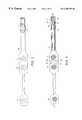
- FIG. 1is a perspective view of the smart sensor of the present invention and mating receptacle.
- FIG. 2is a top plan view of the smart sensor shown in FIG. 1 .
- FIG. 3is a plan view of the underside of the smart sensor shown in FIG. 1 .
- FIG. 4 ( a )is a perspective exploded view of the plastic molded interface platform, showing the mounting of the terminal tab and smart card memory module, and ground guard.
- FIGS. 4 ( b ) and 4 ( c )are perspective views of the assembled plastic molded interface platform, showing the mounting of the terminal tab and smart card memory device, and ground guard.
- FIG. 5is a perspective view of a smart sensor consisting of several smart electrodes.
- FIGS. 6 ( a ) and 6 ( b )are perspective views of the plastic molded interface platform ready for insertion and fully inserted, respectively, into the mating receptacle.
- FIG. 7is a side cross-sectional view mating receptacle, showing the electrical contact surfaces, the living hinge door and the wiping surfaces of the receptacle.
- FIG. 8is a cross-sectional view of the mating connector showing the electrical contact surfaces.
- FIG. 9is an end elevational view of the smart sensor receptacle showing the hinged door and the rail alignment channels.
- FIG. 10 ( a )is a top plan view and FIG. 10 ( b ) is a bottom plan view of two alternate embodiments of the smart sensor in which the memory module is mounted on the top side and the underside of the flexible substrate respectively.
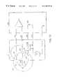
- FIG. 11is a schematic diagram of the ground fault detection circuit used in the smart sensor shown in FIG. 1 .
- FIG. 12is a schematic diagram of the ground guard protection circuit used in the smart sensor shown in FIG. 1 .
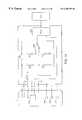
- FIG. 13is a schematic diagram of the smart sensor connection detection circuit.
- FIG. 14is a schematic diagram of an alternate embodiment of the smart sensor connection detection circuit.
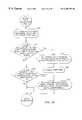
- FIG. 15is a flowchart of the data string acquisition routine used by the smart sensor shown in FIG. 1 .
- FIG. 16is a flowchart of the digital signature validation algorithm used by the smart sensor shown in FIG. 1 .
- FIG. 17is a flowchart of the verification algorithm used by the smart sensor shown in FIG. 1 .
- FIG. 18is a flowchart of the data logging algorithm used by the smart sensor shown in FIG. 1 .
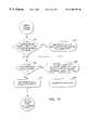
- FIG. 19is a flowchart of the usage count verification algorithm used by the smart sensor shown in FIG. 1 .
- FIG. 20is a flowchart of the type and expiration check algorithm used by the smart sensor shown in FIG. 1 .
- the mechanical aspects of the sensor system of the present inventionare based on a plastic molded interface and mounting platform that serves as an assembly base for the various components of the system.
- the interface platformensures that the system components are maintained in the correct relative alignment and provides sufficient mechanical stiffness to enable the terminal tab/smart sensor/interface platform assembly to be removably inserted into a mating receptacle.
- the union of the smart sensor 2 and the mating receptacle 6achieves an electrical connection between the components of the smart sensor 2 and the associated monitor.
- the monitormay then perform analysis and/or recording of the acquired biopotentials.
- the perspective viewshows the entire smart sensor assembly.
- Thisincludes the smart sensor 2 with an integral plastic molded interface and mounting platform 4 , and the mating receptacle 6 .
- the plastic molded interface platform 4serves as a structure to which a memory module and terminal tab of the sensor substrate are mounted and also holds these components in proper alignment for insertion into the mating receptacle 6 .
- the mating receptacle 6is connected to a monitor (not shown) by a cable 8 .
- the mating receptacle 6is sealed to prevent the ingress of liquids and provides a wiping action to prevent the insertion of a wet plastic sensor tab.
- FIG. 2shows the flexible substrate 10 that serves as a substrate for the electrodes 20 , 21 , 22 of the electrode array and the set of printed conductors which electrically connect the electrodes to the mating receptacle 6 .
- the positions of the array of three electrodes 20 , 21 , 22are delineated by the circle locations.
- the plastic molded interface platform 4serves as the connecting platform.
- a thumb grip 25facilitates insertion of the molded interface platform 4 into the mating receptacle 6 .
- FIG. 3shows the three electrodes 20 , 21 , 22 from the bottom side.
- These electrodescontain conductive gel, a gel-retaining sponge 30 , 31 , 32 and self-prepping times of the type described in U.S. Pat. No. 5,305,746, the teachings of which are incorporated herein by reference.
- These electrodesincorporate gel blowout compartments 35 and salt-bridge barriers 38 ; these features provide a location for excess gel to expand into and prevent excess gel from short-circuiting adjacent electrodes or lifting the sensor off the skin.
- the plastic molded interface platform 4serves as a mounting and interfacing platform for the smart card memory module 40 and the proximal end of the flexible circuit substrate 10 , referred to as the terminal tab 45 .
- Adhesively mounting the terminal tab and the memory module 40 on the interface platformholds these components in precise alignment to each other, so that the printed conductors 50 on the terminal tab 45 and the contact pads 42 of the memory module 40 are positioned to make the proper electrical contact upon insertion of the interface platform 4 into the mating receptacle 6 .
- the memory module 40 and the terminal tab 45are mounted on the interface platform 4 so that they are physically and electrically separate. This prevents current from the electrical power supply of the memory module 40 from coming into contact with the patient-connected printed conductors 50 on the terminal tab 45 , acting to assure patient safety.
- a ground guard trace 55 that encircles the exposed contacts 53 of the printed conductors 50serves as a further means of patient protection.
- the ground guard trace 55acts as a current sink thus preventing an electrical path between the memory module 40 and the printed conductors 50 , as might occur in the event of ingress of liquid into the mating receptacle 6 .
- the smart sensor plastic molded interface platform assemblyis shown in FIG. 4 ( a ).
- the precisely formed plastic molded interface platform 4is preferably molded of acrylonitrile butadiene styrene (ABS) plastic.
- ABSacrylonitrile butadiene styrene
- the memory module 40 and the terminal tab 45 of the flexible plastic substrateare permanently attached to the interface platform 4 with a drop of liquid adhesive or a hot melt adhesive laminate.
- the memory module 40has a protrusion (not shown) on the side opposite from the electrical contact pads 42 .
- the protrusionfits into an alignment cavity 430 on the interface platform 4 .
- This cavity 430serves as a mounting point for the memory module 40 , ensuring proper positioning during manufacturing.
- the flexible plastic substrate 10is preferably constructed of polyester, on one side of which are printed conductors 50 using conductive ink, preferably silver (Ag). These printed conductors 50 make connection to the biopotential electrodes 20 , 21 , 22 of the plastic substrate 10 .
- the terminal tab 45is adhesively attached to the tab mounting point 440 of the interface platform 4 such that the side of the tab 45 bearing the printed conductors 50 is opposite the interface platform 4 .
- the interface platform 4incorporates a raised portion 450 that presses the printed conductors 50 against the contact points (not shown) inside the mating receptacle 6 .
- FIG. 4 ( b )shows the underside of the interface platform 4 with the attached memory module 40 and terminal tab 45 .
- the smart card memory module 40 used in the inventionincorporates integral electrical contact pads 42 on the module 40 itself. In the completed assembly, the surfaces of these pads 42 are aligned in the same orientation as the surfaces of the printed conductors 50 of the terminal tab 45 .
- the integration of the memory module contact pads 42 on the memory module 40has the important advantage of obviating the need for additional printed conductors on the flexible substrate to provide an electrical connection point for the memory module 40 .
- a further advantageis that the electrical paths of the memory module connections are independent of those that connect the electrodes 20 , 21 , 22 to contact points in the mating receptacle 6 .
- the relative placement of the memory module 40 and terminal tab 45ensures that the printed conductor patient leads 50 will not momentarily come into contact with the memory module power supply and logic lines on the contact pads 42 during insertion and removal of the interface platform 4 from the mating receptacle 6 .
- Physical separation of the analog signals carried on the printed conductor patient leads 50 and the digital signals on the memory module contact pads 42enhances the noise immunity of the acquired signals.
- Further enhancing patient safetyis an additional printed conductor 55 that serves as a grounded guard trace.
- the ground guardserves as a collection path for any stray electrical current that might result from a fault condition. It is placed between the contact pads 42 of the memory module 40 and the printed conductor patient leads 50 in such a manner that it provides a barrier to any current that might leak from the memory module contact pads 42 .
- FIG. 4 ( c )shows the top of the interface platform 4 .
- the side of the flexible substrate 10 opposite that bearing the printed conductorsmay be seen 420 .
- the interface platform 4incorporates a finger grip 475 which indicates where the interface platform 4 should be grasped. This helps to avoid finger contact with the exposed electrical contact surfaces on the underside of the interface platform 4 , thus minimizing the risk of poor connection impedances due to residual epidermal oils.
- the interface platform 4also incorporates a finger stop 480 which enables the user to exert the moderate degree of force necessary to firmly slide the interface platform into the mating receptacle.
- a pair of keyed alignment rails 485along each side of the portion of the interface platform 4 that is inserted into the mating receptacle 6 .
- the rails 485ensure that the interface platform 4 can be inserted into the receptacle 6 in only one possible alignment.
- a retaining depression 490 and retaining restraint 495are also incorporated into the interface platform 4 .
- various alternative embodiments of the smart sensormay be constructed by substituting individual electrodes for some or all of the electrodes in the electrode array, by providing individual interface platforms for some or all of the electrodes, and by varying the location of the memory module.
- Individual electrodes substituted for some or all of the electrodes of the electrode arraymay have individual interface platforms, or may connect to a common interface platform, or a combination of the two.
- the memory module 40may be placed on the electrode array substrate 10 , on one of the individual electrodes 20 , 21 , 22 , in a cable connecting the electrode array to a mating receptacle or monitor, or on or in an interface connector attached to the electrode array and connecting it to the mating receptacle.
- smart electrodesmay be constructed by placing memory modules 40 on the substrate 10 carrying an individual electrode 15 as shown in FIG. 5, on each individual electrode 20 , 21 , 22 , or on or in the interface connector of the smart electrode 18 ; a set of smart electrodes may then be connected by individual or common interface connectors to a mating receptacle 6 or monitor, creating a smart sensor.
- Such alternate embodimentsare functionally equivalent to the preferred embodiment described above.
- the mating receptacle 6contains numerous features specific to this invention and is an integral part of the smart sensor system of the present invention.
- a view of the interface platform 4 properly aligned for insertion into the mating receptacle 6is shown in FIG. 6 ( a ).
- the mating receptacle 6may be attached to a biopotential signal monitor (not shown) containing a processor either directly or by means of an intermediary connecting cable 8 .
- the interface platform 4is inserted into the mating receptacle 6 until the finger stop 480 makes contact with the end face 540 of the mating connector 6 .
- the portion 550 of the interface platform 4 that is insertedincludes both the attached memory module 40 and the attached end of the terminal tab 45 bearing the printed conductors 50 .
- both the contact pads 42 on the memory module 40 and the printed conductors 50 on the terminal tab 45make contact with electrical contact points (not shown) within the mating receptacle 6 . This establishes an electrical connection between the printed conductors 50 of the electrode array 20 , 21 , 22 and the memory module 40 on one hand, and the internal conductors (not shown) of the connecting cable 8 of the signal monitor on the other.
- the mating receptacle 6also incorporates a beryllium-copper retaining finger 630 that engages the retaining depression 490 when the interface platform 4 is fully inserted into the mating receptacle 6 .
- the retaining finger 630exerts a counter force against the retaining restraint 495 , preventing the interface platform 4 from being inadvertently withdrawn from the receptacle 6 .
- Pressing on the release button 560lifts the retaining finger 630 out of the retaining depression 490 and clear of the retaining restraint 495 , so that the interface platform 4 may be removed from the receptacle 6 and the smart sensor 2 disconnected when desired.
- the retaining finger 630will yield and the interface platform 4 will then detach to prevent patient injury caused by a falling monitor.
- FIGS. 7 and 8illustrate several additional features of the mating receptacle 6 .
- a cross section through the mating receptacle 6 perpendicular to the plane of the interface platform mounting surfaceis shown in FIG. 7 .
- the opening into which the interface platform 4 is insertedis normally sealed by the hinged door 610 made of thermoplastic elastomer.
- the door 610serves to bar liquids from entering the mating receptacle 6 when the interface platform 4 is not inserted, an important feature in a hostile environment such as an operating room.
- the action of inserting the interface platform 4 into the mating receptacle 6pushes the door 610 open and out of the way. Liquids are further barred from entry into the receptacle by two wiping surfaces 620 .
- These wiping surfaces 620are part of the thermoplastic elastomer outer sleeve 640 of the mating receptacle 6 .
- This soft sleeve 640minimizes pressure indentations in a patient's skin when the mating receptacle 6 is positioned such that a patient is lying on it.
- the electrical contact points 638 for the exposed contacts of the printed conductors 53 and the electrical contact points 635 for the memory module contact pads 42are also shown in the closed position. The electrical contact points are also shown from a different orientation in FIG. 8 .
- FIG. 9shows an end-on cross-sectional view through the hinged door 610 from the direction of the end of the mating receptacle 6 which accepts the interface platform 4 .
- the rail alignment channels 650receive the keyed alignment rails 485 , ensuring proper alignment of the interface platform 4 as it is inserted into the mating receptacle.
- the memory module 40is mounted directly on the flexible substrate 10 , opposite the side bearing the electrodes.
- the memory module 40is mounted with its contact pads 42 against the flexible substrate 10 .
- Additional printed conductors 50are provided on the flexible substrate on the same side as the memory module 40 to connect the contact pads 42 of the memory module 40 to exposed contacts on the terminal tab 45 for connection to the monitor via a mating connector.
- the terminal tab 45thus has exposed contacts on both sides.
- the mating connectorcontains additional electrical contact points for the printed conductors electrically connected to the memory module 40 in place of contact points for the memory module contact pads 42 .
- FIG. 10 ( a )the embodiment shown in FIG.
- the memory module 40is mounted on the same side of the flexible substrate 10 as the electrodes.
- This designsimplifies the smart sensor construction by requiring printed conductors 50 on only one side of the flexible substrate 10 . Adequate insulation must be provided, however, to protect the patient from a possible fault condition arising from the close proximity to the skin of the smart sensor current supply conductor.
- the patient interface circuits 811incorporate a ground fault detection circuit 833 .
- the Field Programmable Gate Array (FPGA) 818shuts down the power to the memory module 40 . If the fault is still detected, the FPGA 818 then shuts down the power supplying the instrumentation amplifier 810 and alerts the monitor 840 that a shutdown has occurred.
- the sequential shutdown of first the memory module 40 and then the instrumentation amplifier 810allows the monitor to localize the failure to either of these components. A hard re-boot is necessary to restore monitoring.
- a potential single fault conditionis the failure of the insulation between the smart chip power connection V+ 808 and one of the patient connections 804 , 805 . This could occur, for example, if the mating receptacle 6 were to be wet with a conductive solution such as saline.
- An electrical path represented by resistor 809would form an electrical bridge between the memory module power line 819 and the patient connection, e.g. 804 .
- Currentwould flow through the patient 800 as indicated by the arrows, traveling through patient connection 804 , patient electrode impedances 801 , 803 , through ground electrode connection 806 , and into the ground of the instrumentation amplifier 810 .
- the International Electrotechnical Commissionhas set the maximum permissible current at 50 micro-amperes in a single fault condition, defined as “patient auxiliary current.” Current in excess of this limit is detected in the present invention by using sense resistor 812 to convert the current flow from the patient to ground into a voltage. This current-proportional voltage is amplified by the circuit consisting of operational amplifier 815 and resistors 813 , 814 . Comparators 816 , 817 compare the amplified current-proportional voltage to reference voltages 830 , 835 and output digital signals 820 , 821 which indicate whether or not the patient auxiliary current has been exceeded. Reference voltages 830 , 835 are equal in magnitude, but of opposite sign; 835 is positive, 830 is negative with respect to ground.
- the magnitude of reference voltages 830 , 835is equal to the magnitude of the output voltage of operational amplifier 815 when the current through sense resistor 812 is 50 micro-amperes. If the polarity of the current through sense resistor 812 is positive, signal 820 will be at the negative saturation voltage of comparator 816 if the output voltage of amplifier 815 is greater than reference voltage 835 , and at the positive saturation voltage of comparator 816 if the output voltage of amplifier 815 is less than reference voltage 835 .
- FPGA 818notifies the monitor 840 , which shuts off power to the patient interface circuits 811 , causing the current to cease.
- the monitordisplays an error message signaling the operator to rectify the condition.
- the monitor softwaremust be re-booted for operation to continue.
- ground fault detection circuit 833 in the preferred embodimentis only in the patient ground circuit, those skilled in the art will recognize that any patient connected circuit could contain a fault sensing circuit.
- the patient interface circuits 811incorporate a ground guard conductor 55 that surrounds the patient-connected conductors 834 , 838 .
- insulationis achieved between the memory module power conductor 819 and the patient conductors 834 , 838 by physical separation. This insulation can be compromised in a fault condition such as the wetting of the connector with a conductive solution such as saline, which may result in current flowing from the memory module power conductor 819 into the patient-connected conductors 834 , 838 .
- an exposed electrical guard conductor 55is interposed between the memory module power conductor 819 and the patient-connected conductors 834 , 838 .
- an electrical path represented by resistor 825would then form an electrical bridge between the power line 819 and the guard conductor 55 .
- Currentwould flow as indicated by the arrows from the memory module power line 819 , through the bridge 825 into the ground guard conductor 55 and though the ground conductor 826 into the patient interface circuit ground 836 .
- the currentwould be shunted harmlessly away from the patient.
- an alternate embodiment to detect the connection of a smart sensor 2 to the patient interface circuits 811makes use of a dedicated conductor loop 839 in the smart sensor, each end of which connects to contacts in the mating receptacle.
- One of these contactswould be connected to the voltage supply of the monitor through a current limiting and sensing resistor 824 , the other would be connected to ground.
- Current flow through the resistor 824is detected using the comparator 832 and the resistors 828 , 829 , 831 , 837 , whose values are selected in the manner described above so that the output of comparator 832 is a logic high when no smart sensor is connected and a logic low when a smart sensor is connected, causing current to flow.
- Smart card technologyprovides unique benefits in this application; such modules are ideally suited to this invention due to the inherent security provided by its design and operation.
- the small size of the smart card memory module die(1 mm 2 ) ensures that flexing of the interface platform 4 will not fracture it.
- the physical layout of the wire leads from the diemake it difficult to physically or electrically probe the module (e.g., with an oscilloscope) in order to sample the bi-directional transmitted data.
- the smart card memory module 40is shipped to the manufacturer in a locked state to provide security during delivery. In the locked state, it is not possible to read from or write to the memory module 40 ; the smart sensor manufacturer using a transport code generated by the manufacturers of the smart card module must first enable it.
- the smart sensor manufacturerunlocks the memory module 40 during the programming stage of the manufacturing process. Further, once the memory module 40 is relocked, it may be written to only once (with the exception of the counter). This provides an additional layer of security, as the data on the memory module 40 cannot subsequently be changed. Those skilled in the art will recognize that many different smart card-type memory modules 40 may be used in its place.
- the manufacturer of the smart card memory module 40also writes a binary data string referred to as a Manufacturer Code to a read-only (ROM) area of the memory module 40 .
- This codeis unique to those memory modules 40 sold to the purchaser (the manufacturer of the smart sensor 2 ) and only that purchaser (the smart sensor manufacturer) may purchase modules containing this code. Because this code is in ROM, it may not be altered and thus serves as an identifier of the source of products containing the smart card memory module.
- a smart card memory module 40is further differentiated from a typical semiconductor memory device (e.g., an SGS-Thomson ST24C02, a 2 Kilobit EEPROM) by a different communication protocoL
- a typical semiconductor memory devicee.g., an SGS-Thomson ST24C02, a 2 Kilobit EEPROM
- the difference in protocols between the smart card memory module 40 and an EEPROMprevents the construction of a counterfeit smart sensor using a non-smart card memory module 40 .
- the monitorverifies that the PROM use bit is set to a 1 and that the number of remaining uses, as represented by the number of usage counter bits set to 1, is greater than zero.
- the smart sensor 2is successfully authenticated, one of the usage counter bits is set to zero, decrementing the number of allowable uses by one.
- the usage counter bitsare set to zero starting with the least significant and progressing to the most significant.
- the monitorwrites to the PROM use bit, setting it to zero and resetting the usage counter bits to 1's. This effectively prevents the subsequent use of the smart sensor 2 (beyond the present use), since the condition that the PROM use bit be 1 will fail Further, since it is not possible to reset the use bit to a 1, the usage counter cannot be “reloaded”.
- the original message Mmay be recovered from the encrypted message C by applying the related decryption algorithm f d to C using the decryption key D.
- Asymmetric algorithmsuse different encryption and decryption keys. Symmetric algorithms are typically computationally less intensive but have the weakness that the same key is used both to encrypt and decrypt the message. Thus knowledge of the decryption key and of the decryption algorithm (both of which might be obtained by reverse engineering the monitor software) would allow a potential counterfeiter to produce smart sensors with validly encrypted device data.
- the source of the smart sensor 2is authenticated and the integrity of its data validated by using a “digital signature.”
- Signature generationrequires the use of a “hash” function (h), which operates on a message to produce an output sequence that is specific to the content of the message itself. If the message M changes, so will the hashed message h(M).
- the digital signature (S)is generated using a signature generation function f s , which typically uses both the private (E) and public (D) keys as well as the hashed message h(M).
- the signatureis typically made up of 2 data sequences, S 1 and S 2 .
- the message Mis encrypted using the private key.
- the encrypted message Cis then written to the smart sensor 2 along with the digital signature (S 1 ,S 2 ).
- the monitorUpon reading the data from the smart sensor 2 , the monitor first decrypts the message using the public key to obtain M.
- the digital signatureis then verified by the signature verification function f v which first applies the hash function to M and then uses h(M) in conjunction with the internally stored public key (D) and the components of the signature to verify that the derived value is equivalent to one of the signature components.
- the signatureis validated. This will occur if and only if the public key D and the private key E used to encrypt the data are the unique related pair and if the message M used to verify the signature is the same as that used to generate the signature. Thus, if the signature can be verified, it must have been generated using the unique private key that corresponds to the public key used for the verification. Since the only holder of the correct private key is the authorized smart sensor manufacturer, successful signature verification ensures that the smart sensor 2 indeed originated at an authorized source. In addition, the successful verification of the signature means that the message used to verify the signature must be the same as that used to create the signature (otherwise h(M) would be different). Thus, successful verification of the signature validates the integrity of the data stored on the smart sensor 2 .
- the decryption key in useis coded by the key code, which is stored in the smart sensor memory.
- the public keys corresponding to each of the stored key codesmay be integrated into the monitor software.
- the authentication programwill use the key code to either determine the correct public key to be used for decryption and digital signature validation before the decryption process begins or to promptly expire a key.
- the smart sensor systemallows for regular changes in the set of public keys in use by the authentication program by subsequent updates to the monitor software.
- the private keyis changed in the manufacturing process, and this change is reflected in the key codes.
- the monitorEach time the smart sensor 2 is disconnected from and reconnected to the same or a different monitor or each time the monitor is restarted, the monitor first resets the data string acquisition routine and waits for the detection of a smart sensor connection at the mating receptacle 6 in step 902 .
- the detectionis performed by the monitor's sensor interface electronics, shown in FIG. 13 . It consists of a current sensing circuit that monitors the current in the power conductor of the smart sensor memory module 40 .
- the data acquisition routineUpon detection of a smart sensor connection in step 904 , the data acquisition routine interrogates the smart sensor in step 906 , requesting that the smart sensor 2 transmit the stored sensor data string. The smart sensor 2 responds to this request by sending the sensor string to the monitor in step 908 .
- the data acquisition routineAfter receiving the sensor data string from the smart sensor 2 in step 910 , the data acquisition routine passes the string to the digital signature validation routine in step 912 .
- the digital signature validation routinefirst parses the sensor data string into its constituent parts, the digital signature string and the device data string in step 920 . Then in step 922 , it uses the manufacturer code to verify the smart sensor memory module 40 is one that was purchased by the smart sensor manufacturer. If this condition is not met, the test is repeated up to 3 more times in step 924 . After the fourth failure, a message indicating that the connected sensor is an illegal device is displayed on the monitor screen in step 926 and the monitor will terminate the authentication program and refuse to proceed with data collection in step 928 . If the manufacturer code is determined in step 922 to be valid, the digital signature validation routine uses the decryption algorithm and the embedded public key to decode the device data string in step 930 .
- step 940the authentication software verifies that the value of the sensor type code corresponds to one of the possible values stored in a look-up table in the authentication software. If the sensor code is a valid value, then the smart sensor 2 is accepted as authentic in step 942 . Otherwise, a message indicating that the connected sensor is an illegal device is displayed on the monitor screen in step 944 and the monitor will terminate the authentication program and refuse to proceed with data collection in step 946 .
- the monitormaintains a log of the set of smart sensor parameters in its internal nonvolatile memory, with a separate entry for each smart sensor 2 which has been authenticated by a given monitor, as determined by the smart sensor serial number and lot code.
- the logged parametersinclude the current date and time, the sensor type, the OEM code, and the smart sensor serial number and lot code.
- a usage counteris also associated with each entry in the log.
- Sufficient memoryis reserved in the nonvolatile memory for this purpose to enable the log to contain entries from some large number of smart sensors 2 ( 200 in the preferred embodiment); when the log is full, the oldest entry is deleted to create memory space for the newest entry.
- a representative of the manufacturermay download the sensor usage log onto a personal computer. The manufacturer may use this data to resolve quality control issues.
- the authentication softwarechecks if a record in the log has the serial number and lot code of the current smart sensor 2 in step 950 . If so, the existing record is used for the currently connected smart sensor. If such a record does not exist, a new log entry is created and its fields are loaded with the data values obtained from the device data string in step 952 . The current date and time are also recorded. After creation of the record or if such a record does exist, the monitor software next updates the usage counters.
- the authentication softwareAfter logging the smart sensor data, the authentication software, in step 954 first synchronizes the usage counters by determining the number of remaining allowable uses and writing that value to the usage counters maintained in the monitor's smart sensor log and on the smart sensor 2 . If a new record has just been created for the current smart sensor 2 (identified by serial number and lot code), the number of remaining allowable uses is calculated as the minimum of the value in the usage counter of the connected smart sensor 2 and the maximum number of allowable uses.
- the number of remaining allowable usesis calculated as the minimum of the value in the usage counter of the monitor's smart sensor log and the value of the usage counter on the connected smart sensor 2 in step 956 .
- the usage count field in the log and the usage counter in the smart sensor 2are then both updated with the calculated number of remaining allowable uses in step 958 .
- step 960the authentication software next tests whether the value of the synchronized usage counters (the number of uses remaining) is less than the maximum number allowable but greater than 0; if so, the monitor will display a message to the user in step 962 with the number of previous uses and will warn that the performance of the smart sensor 2 may be unreliable.
- the authentication softwaretests whether the value of the synchronized usage counters is zero in step 964 . If so, the maximum number of uses has been reached and the monitor will alert the user in step 966 and disallow the use of the smart sensor 2 in step 968 . If the usage counter is greater than zero, the authentication software will decrement both usage counters in step 970 .
- This sensor usage checkthus prevents a smart sensor 2 from being used more than the allowable number of times, regardless of which monitor the smart sensor 2 has been connected to. This outcome is obtained even if the usage counter on the smart sensor 2 was reset to the initial value by an unauthorized method; the actual number of times that smart sensor 2 has been used is logged in the monitor and will be reloaded onto the smart sensor 2 when it is reconnected.
- the monitoruses the sensor type code to select one of several internal processing algorithms appropriate to the specific smart sensor 2 and application in step 980 .
- the sensor type codemay also be used to switch the inputs to the monitor's instrumentation amplifiers if a signal is to be multiplexed.
- a particular alternate embodiment of the smart sensor systemuses the smart sensor memory module 40 as a means of customizing software in the monitor 840 .
- the monitor 840calculates a diagnostic index in the manner taught by Chamoun, et aL in U.S. Pat. 5,458,117 which is assigned to the assignee of the present application and the teachings of which are incorporated herein by reference
- the index coefficientsmay be stored in the smart sensor memory module 40 and transferred to the monitor 840 during the configuration procedure. These coefficients would then be used by the monitor 840 to calculate the diagnostic index Specific smart sensors intended for different applications may have different sets of coefficients stored in their memory modules during the manufacturing process.
- the smart sensor memory module 40may be used as a means of upgrading that portion of the monitor software that calculates the diagnostic index.
- the various variables in the diagnostic indexnot only may different coefficients of the various variables in the diagnostic index be optimized for different applications, but the mathematical structure of the diagnostic index itself may be varied; ie., the variables in the index, their coefficients, and how they are combined may all be specified.
- This embodimentwill greatly expand the flexibility of the smart sensor system by removing restrictions on the mathematical structure of the diagnostic index.
- the entire monitor softwaremay be stored in the smart sensor memory module.
- the monitor softwaremay consist of only sufficient software to transfer the contents of the smart sensor memory module to the monitor 840 and then to run that software.
- Such softwarewill include that portion which calculates the diagnostic index, as well as the portions that handle data acquisition, data display, communication with the user, etc.
Landscapes
- Health & Medical Sciences (AREA)
- Life Sciences & Earth Sciences (AREA)
- Molecular Biology (AREA)
- Surgery (AREA)
- Biophysics (AREA)
- Pathology (AREA)
- Engineering & Computer Science (AREA)
- Biomedical Technology (AREA)
- Heart & Thoracic Surgery (AREA)
- Medical Informatics (AREA)
- Veterinary Medicine (AREA)
- Physics & Mathematics (AREA)
- Animal Behavior & Ethology (AREA)
- General Health & Medical Sciences (AREA)
- Public Health (AREA)
- Cardiology (AREA)
- Measurement And Recording Of Electrical Phenomena And Electrical Characteristics Of The Living Body (AREA)
- Measurement Of The Respiration, Hearing Ability, Form, And Blood Characteristics Of Living Organisms (AREA)
- Measuring And Recording Apparatus For Diagnosis (AREA)
- Investigating Or Analysing Biological Materials (AREA)
- Measuring Or Testing Involving Enzymes Or Micro-Organisms (AREA)
Abstract
Description
| Device Data String: |
| Manufacturer | Key | OEM | Lot | Shelf | Sensor | Serial |
| Code | Code | Code | Code | Life | Type | Number |
| Sensor Data String: |
| Device Data String | Digital Signature | ||
Claims (53)
Priority Applications (10)
| Application Number | Priority Date | Filing Date | Title |
|---|---|---|---|
| US09/328,945US6298255B1 (en) | 1999-06-09 | 1999-06-09 | Smart electrophysiological sensor system with automatic authentication and validation and an interface for a smart electrophysiological sensor system |
| DE60038488TDE60038488T2 (en) | 1999-06-09 | 2000-06-09 | INTELLIGENT ELECTROPHYSIOLOGICAL PROBE SYSTEM WITH HEALTH AND VALIDITY TESTING |
| AU79815/00AAU780076B2 (en) | 1999-06-09 | 2000-06-09 | A smart electrophysiological sensor system with automatic authentication and validation |
| EP00970431AEP1182965B1 (en) | 1999-06-09 | 2000-06-09 | A smart electrophysiological sensor system with automatic authentication and validation |
| AT00970431TATE390886T1 (en) | 1999-06-09 | 2000-06-09 | INTELLIGENT ELECTROPHYSIOLOGICAL SENSOR SYSTEM WITH AUTHENTICITY AND VALIDITY CHECK |
| CA002371858ACA2371858C (en) | 1999-06-09 | 2000-06-09 | A smart electrophysiological sensor system with automatic authentication and validation |
| PCT/US2000/015976WO2000078213A2 (en) | 1999-06-09 | 2000-06-09 | A smart electrophysiological sensor system with automatic authentication and validation |
| JP2001504284AJP2003502092A (en) | 1999-06-09 | 2000-06-09 | Electrophysiology smart sensor system for automatic genuine / validation verification |
| BRPI0011434-0ABR0011434B1 (en) | 1999-06-09 | 2000-06-09 | intelligent sensor for the acquisition of electrophysiological signals, intelligent sensor system and interface for an intelligent sensor. |
| MXPA01012689AMXPA01012689A (en) | 1999-06-09 | 2000-06-09 | A smart electrophysiological sensor system with automatic authentication and validation. |
Applications Claiming Priority (1)
| Application Number | Priority Date | Filing Date | Title |
|---|---|---|---|
| US09/328,945US6298255B1 (en) | 1999-06-09 | 1999-06-09 | Smart electrophysiological sensor system with automatic authentication and validation and an interface for a smart electrophysiological sensor system |
Publications (1)
| Publication Number | Publication Date |
|---|---|
| US6298255B1true US6298255B1 (en) | 2001-10-02 |
Family
ID=23283155
Family Applications (1)
| Application Number | Title | Priority Date | Filing Date |
|---|---|---|---|
| US09/328,945Expired - LifetimeUS6298255B1 (en) | 1999-06-09 | 1999-06-09 | Smart electrophysiological sensor system with automatic authentication and validation and an interface for a smart electrophysiological sensor system |
Country Status (10)
| Country | Link |
|---|---|
| US (1) | US6298255B1 (en) |
| EP (1) | EP1182965B1 (en) |
| JP (1) | JP2003502092A (en) |
| AT (1) | ATE390886T1 (en) |
| AU (1) | AU780076B2 (en) |
| BR (1) | BR0011434B1 (en) |
| CA (1) | CA2371858C (en) |
| DE (1) | DE60038488T2 (en) |
| MX (1) | MXPA01012689A (en) |
| WO (1) | WO2000078213A2 (en) |
Cited By (225)
| Publication number | Priority date | Publication date | Assignee | Title |
|---|---|---|---|---|
| US20020095078A1 (en)* | 2000-08-31 | 2002-07-18 | Mannheimer Paul D. | Oximeter sensor with digital memory encoding sensor expiration data |
| US20020161385A1 (en)* | 2000-10-20 | 2002-10-31 | Ethicon Endo-Surgery, Inc. | Apparatus and method for alerting generator functions in an ultrasonic surgical system |
| US20020193709A1 (en)* | 2001-05-23 | 2002-12-19 | Rudiger Bolze | Apparatus for administering acoustic shock waves having a removable and replaceable component a data storage medium |
| US20030009111A1 (en)* | 2001-06-13 | 2003-01-09 | Cory Philip C. | Non-invasive method and apparatus for tissue detection |
| US6527724B1 (en)* | 1998-12-04 | 2003-03-04 | Consiglio Nazionale Delle Richerche | Catheter guidance by magnetocardiographic mapping |
| WO2003052683A1 (en)* | 2001-12-19 | 2003-06-26 | Giesecke & Devrient Gmbh | Measuring device for the detection of physiological variables |
| US20030126423A1 (en)* | 2001-12-28 | 2003-07-03 | Crossroads Systems, Inc. | Electronic branding technology |
| WO2003057030A1 (en)* | 2002-01-08 | 2003-07-17 | Masimo Corporation | Physiological sensor combination |
| NL1019789C2 (en)* | 2002-01-18 | 2003-07-21 | A J Van Liebergen Holding B V | Connector and electrode combination, especially for measurements on human body, has additional signal carrier connectable to responder |
| US6595930B2 (en)* | 2000-10-27 | 2003-07-22 | Mipm Mannendorfer Institut Fur Physik Und Medizin Gmbh | Probe for physiological pressure measurement in the human or animal body and method for monitoring the probe |
| US6600940B1 (en) | 2000-08-31 | 2003-07-29 | Mallinckrodt Inc. | Oximeter sensor with digital memory |
| US20030163052A1 (en)* | 2002-02-27 | 2003-08-28 | Mott Eric V. | Connector for interfacing intravascular sensors to a physiology monitor |
| US6622050B2 (en)* | 2000-03-31 | 2003-09-16 | Medtronic, Inc. | Variable encryption scheme for data transfer between medical devices and related data management systems |
| US6628975B1 (en) | 2000-08-31 | 2003-09-30 | Mallinckrodt Inc. | Oximeter sensor with digital memory storing data |
| US20040006261A1 (en)* | 2000-08-31 | 2004-01-08 | Nellcor Puritan Bennett Inc. | Oximeter sensor with digital memory encoding patient data |
| US6676600B1 (en)* | 1999-09-03 | 2004-01-13 | Tensys Medical, Inc. | Smart physiologic parameter sensor and method |
| US6708049B1 (en)* | 1999-09-28 | 2004-03-16 | Nellcor Puritan Bennett Incorporated | Sensor with signature of data relating to sensor |
| WO2004019751A3 (en)* | 2002-08-06 | 2004-07-29 | Steute Schaltgeraete Gmbh & Co | Assembly and method for the wireless transmission of actuating signals to medical equipment |
| US20040171935A1 (en)* | 2004-03-12 | 2004-09-02 | Siemens Medical Solutions Usa, Inc. | Ultrasound transducer probe identification for security and other purposes |
| US20040267103A1 (en)* | 2001-10-22 | 2004-12-30 | Luya Li | Physiological parameter monitoring system and sensor assembly for same |
| US20050027311A1 (en)* | 2000-10-20 | 2005-02-03 | Wiener Eitan T. | Apparatus and method for altering generator functions in an ultrasonic surgical system |
| US20050027286A1 (en)* | 2000-12-15 | 2005-02-03 | Laserscope | Method and system for photoselective vaporization of the prostate, and other tissue |
| US20050113704A1 (en)* | 2003-11-26 | 2005-05-26 | Lawson Corey J. | Patient monitoring system that incorporates memory into patient parameter cables |
| US20050272389A1 (en)* | 2004-06-02 | 2005-12-08 | Microelectronics Technology Inc. | Receiver signal strength indicator having an automatic outputting detection circuit |
| US20050280531A1 (en)* | 2004-06-18 | 2005-12-22 | Fadem Kalford C | Device and method for transmitting physiologic data |
| US20060085049A1 (en)* | 2004-10-20 | 2006-04-20 | Nervonix, Inc. | Active electrode, bio-impedance based, tissue discrimination system and methods of use |
| US20060085048A1 (en)* | 2004-10-20 | 2006-04-20 | Nervonix, Inc. | Algorithms for an active electrode, bioimpedance-based tissue discrimination system |
| US20060106294A1 (en)* | 2004-11-12 | 2006-05-18 | Nonin Medical, Inc. | Sensor assembly |
| US7048687B1 (en)* | 1999-04-14 | 2006-05-23 | Ob Scientific, Inc. | Limited use medical probe |
| US20060130154A1 (en)* | 2004-11-30 | 2006-06-15 | Wai Lam | Method and system for protecting and verifying stored data |
| US20060167351A1 (en)* | 2005-01-21 | 2006-07-27 | Nonin Medical Inc. | Sensor system with memory and method of using same |
| US20060217606A1 (en)* | 2000-08-31 | 2006-09-28 | Nellcor Puritan Bennett Inc. | Oximeter sensor with digital memory encoding sensor data |
| US20060224059A1 (en)* | 1999-03-08 | 2006-10-05 | Nellcor Puritan Bennett Inc. | Method and circuit for storing and providing historical physiological data |
| US20060236128A1 (en)* | 2005-04-04 | 2006-10-19 | Christian Christiansen | Method for authentication of electronic components |
| US20070078298A1 (en)* | 2003-07-02 | 2007-04-05 | Arkady Glukhovsky | Imaging sensor array and device and method for use thereof |
| US20070135697A1 (en)* | 2004-04-19 | 2007-06-14 | Therasense, Inc. | Method and apparatus for providing sensor guard for data monitoring and detection systems |
| US20070135728A1 (en)* | 2005-12-01 | 2007-06-14 | Lexicor Medical Technology, Llc | Systems and Methods for Analyzing and Assessing Depression and Other Mood Disorders Using Electroencephalographic (EEG) Measurements |
| US20070265543A1 (en)* | 2003-12-17 | 2007-11-15 | Vansickle David P | Activeinvasive Eeg Device and Technique |
| US20070295615A1 (en)* | 2006-06-27 | 2007-12-27 | Alcoa Inc. | Systems and methods useful in controlling operations of metal electrolysis cells |
| USD565183S1 (en)* | 2006-08-31 | 2008-03-25 | Objectivision Limited | Flexible printed circuit board electrode assembly for measurement of electrophysiological signals |
| US20080076967A1 (en)* | 2004-05-18 | 2008-03-27 | Scimed Life Systems, Inc. | Serialization of single use endoscopes |
| WO2008054980A3 (en)* | 2006-10-13 | 2008-07-24 | Aspect Medical System Inc | Physiological sensor system with an integrated rfid interrogator system |
| US20080221479A1 (en)* | 2007-03-07 | 2008-09-11 | Ritchie Paul G | Integrated Imaging and Biopsy System with Integrated Utilities |
| WO2009024480A1 (en)* | 2007-08-21 | 2009-02-26 | Endress+Hauser Conducta Gesellschaft Für Mess- Und Regeltechnik Mbh+Co. Kg | Method for checking the compatibility of a measurement system comprising a measuring transducer and a sensor |
| US7509494B2 (en)* | 2002-03-01 | 2009-03-24 | Masimo Corporation | Interface cable |
| US20090097846A1 (en)* | 2006-12-14 | 2009-04-16 | David Robert Kozischek | RFID Systems and Methods for Optical Fiber Network Deployment and Maintenance |
| US20090118595A1 (en)* | 2004-06-15 | 2009-05-07 | Koninklijke Philips Electronics N.V. | Sensor for acquiring physiological signals of a patient |
| US7547150B2 (en) | 2007-03-09 | 2009-06-16 | Corning Cable Systems, Llc | Optically addressed RFID elements |
| US7558552B1 (en)* | 2004-11-19 | 2009-07-07 | Xilinx, Inc. | Integrated circuit and method of generating a bias current for a plurality of data transceivers |
| USD598114S1 (en)* | 2008-08-13 | 2009-08-11 | Neurometrix, Inc. | Bioelectrode |
| US7583190B2 (en) | 2005-10-31 | 2009-09-01 | Abbott Diabetes Care Inc. | Method and apparatus for providing data communication in data monitoring and management systems |
| USD600352S1 (en)* | 2008-08-14 | 2009-09-15 | Neurometrix, Inc. | Bioelectrode |
| US20090259833A1 (en)* | 2008-04-14 | 2009-10-15 | Dell Products, Lp | System and method of enabling a function within a module configured to be used within an information handling system |
| US20090267557A1 (en)* | 2005-05-31 | 2009-10-29 | Borgwarner Inc | Method of actuator control |
| US7620437B2 (en) | 2005-06-03 | 2009-11-17 | Abbott Diabetes Care Inc. | Method and apparatus for providing rechargeable power in data monitoring and management systems |
| US20090312638A1 (en)* | 2006-07-17 | 2009-12-17 | Signostics Pty Ltd | medical diagnostic device |
| USD609353S1 (en)* | 2008-08-13 | 2010-02-02 | Neurometrix, Inc. | Bioelectrode |
| US7679407B2 (en) | 2003-04-28 | 2010-03-16 | Abbott Diabetes Care Inc. | Method and apparatus for providing peak detection circuitry for data communication systems |
| US7727181B2 (en) | 2002-10-09 | 2010-06-01 | Abbott Diabetes Care Inc. | Fluid delivery device with autocalibration |
| US20100137698A1 (en)* | 2003-06-12 | 2010-06-03 | Abbott Diabetes Care Inc. | Method and Apparatus for Providing Power Management in Data Communication Systems |
| US7756561B2 (en) | 2005-09-30 | 2010-07-13 | Abbott Diabetes Care Inc. | Method and apparatus for providing rechargeable power in data monitoring and management systems |
| US7760094B1 (en) | 2006-12-14 | 2010-07-20 | Corning Cable Systems Llc | RFID systems and methods for optical fiber network deployment and maintenance |
| US7768408B2 (en) | 2005-05-17 | 2010-08-03 | Abbott Diabetes Care Inc. | Method and system for providing data management in data monitoring system |
| US7772975B2 (en) | 2006-10-31 | 2010-08-10 | Corning Cable Systems, Llc | System for mapping connections using RFID function |
| US7782202B2 (en) | 2006-10-31 | 2010-08-24 | Corning Cable Systems, Llc | Radio frequency identification of component connections |
| US7837091B2 (en) | 2005-05-20 | 2010-11-23 | Laserscope | Laser system and delivery device operation logging method and kit |
| US20100315110A1 (en)* | 2009-06-10 | 2010-12-16 | Medtronic, Inc. | Hermeticity testing |
| USD633621S1 (en)* | 2009-09-18 | 2011-03-01 | Lifesync Corporation | Leadwear assembly |
| US20110066065A1 (en)* | 2009-08-28 | 2011-03-17 | Lexicor Medical Technology, Llc | Systems and methods to identify a subgroup of adhd at higher risk for complicating conditions |
| US7922458B2 (en) | 2002-10-09 | 2011-04-12 | Abbott Diabetes Care Inc. | Variable volume, shape memory actuated insulin dispensing pump |
| US7946994B2 (en) | 2004-10-07 | 2011-05-24 | Tensys Medical, Inc. | Compact apparatus and methods for non-invasively measuring hemodynamic parameters |
| EP2324759A1 (en)* | 2009-11-24 | 2011-05-25 | General Electric Company | Method and computer program for authenticating a physiological sensor, a sensor system, a patient monitor, and a physiological sensor |
| USD639243S1 (en) | 2006-03-29 | 2011-06-07 | Nuvasive, Inc. | Electrode connector |
| US20110213225A1 (en)* | 2009-08-31 | 2011-09-01 | Abbott Diabetes Care Inc. | Medical devices and methods |
| US8029460B2 (en) | 2005-03-21 | 2011-10-04 | Abbott Diabetes Care Inc. | Method and system for providing integrated medication infusion and analyte monitoring system |
| US8047811B2 (en) | 2002-10-09 | 2011-11-01 | Abbott Diabetes Care Inc. | Variable volume, shape memory actuated insulin dispensing pump |
| US8115635B2 (en) | 2005-02-08 | 2012-02-14 | Abbott Diabetes Care Inc. | RF tag on test strips, test strip vials and boxes |
| US8160669B2 (en) | 2003-08-01 | 2012-04-17 | Dexcom, Inc. | Transcutaneous analyte sensor |
| US8172760B2 (en) | 2009-06-18 | 2012-05-08 | Medtronic, Inc. | Medical device encapsulated within bonded dies |
| WO2012037527A3 (en)* | 2010-09-16 | 2012-05-10 | Neurometrix, Inc. | Apparatus and method for the automated measurement of sural nerve conduction velocity and amplitude |
| US8231531B2 (en)* | 2004-07-13 | 2012-07-31 | Dexcom, Inc. | Analyte sensor |
| US20120203269A1 (en)* | 2011-02-03 | 2012-08-09 | Terumo Kabushiki Kaisha | Medical manipulator system |
| US8248208B2 (en) | 2008-07-15 | 2012-08-21 | Corning Cable Systems, Llc. | RFID-based active labeling system for telecommunication systems |
| US8275437B2 (en) | 2003-08-01 | 2012-09-25 | Dexcom, Inc. | Transcutaneous analyte sensor |
| US8280475B2 (en) | 2004-07-13 | 2012-10-02 | Dexcom, Inc. | Transcutaneous analyte sensor |
| US8311749B2 (en) | 2003-08-01 | 2012-11-13 | Dexcom, Inc. | Transcutaneous analyte sensor |
| US20120330179A1 (en)* | 2011-06-24 | 2012-12-27 | Verathon, Inc. | Electrode contact-quality evaluation |
| US8344966B2 (en) | 2006-01-31 | 2013-01-01 | Abbott Diabetes Care Inc. | Method and system for providing a fault tolerant display unit in an electronic device |
| US8424388B2 (en) | 2011-01-28 | 2013-04-23 | Medtronic, Inc. | Implantable capacitive pressure sensor apparatus and methods regarding same |
| US8467972B2 (en) | 2009-04-28 | 2013-06-18 | Abbott Diabetes Care Inc. | Closed loop blood glucose control algorithm analysis |
| EP2605148A3 (en)* | 2005-06-27 | 2013-10-02 | Nike Incorporated | Systems for activating and/or authenticating electronic devices for operation with footwear and other uses |
| US8560082B2 (en) | 2009-01-30 | 2013-10-15 | Abbott Diabetes Care Inc. | Computerized determination of insulin pump therapy parameters using real time and retrospective data processing |
| US8565848B2 (en) | 2004-07-13 | 2013-10-22 | Dexcom, Inc. | Transcutaneous analyte sensor |
| US8568160B2 (en) | 2010-07-29 | 2013-10-29 | Covidien Lp | ECG adapter system and method |
| US8579853B2 (en) | 2006-10-31 | 2013-11-12 | Abbott Diabetes Care Inc. | Infusion devices and methods |
| US8634901B2 (en) | 2011-09-30 | 2014-01-21 | Covidien Lp | ECG leadwire system with noise suppression and related methods |
| US8666505B2 (en) | 2010-10-26 | 2014-03-04 | Medtronic, Inc. | Wafer-scale package including power source |
| US8668651B2 (en) | 2006-12-05 | 2014-03-11 | Covidien Lp | ECG lead set and ECG adapter system |
| US8694080B2 (en) | 2009-10-21 | 2014-04-08 | Covidien Lp | ECG lead system |
| US8690611B2 (en) | 2007-12-11 | 2014-04-08 | Covidien Lp | ECG electrode connector |
| US8731405B2 (en) | 2008-08-28 | 2014-05-20 | Corning Cable Systems Llc | RFID-based systems and methods for collecting telecommunications network information |
| US8798934B2 (en) | 2009-07-23 | 2014-08-05 | Abbott Diabetes Care Inc. | Real time management of data relating to physiological control of glucose levels |
| US8821405B2 (en) | 2006-09-28 | 2014-09-02 | Covidien Lp | Cable monitoring apparatus |
| US8845536B2 (en) | 2003-08-01 | 2014-09-30 | Dexcom, Inc. | Transcutaneous analyte sensor |
| CN104188624A (en)* | 2014-08-15 | 2014-12-10 | 深圳市理邦精密仪器股份有限公司 | Medical monitoring system and method for automatic recognition sensor |
| CN104246450A (en)* | 2012-03-21 | 2014-12-24 | 株式会社日立制作所 | Sensor device |
| US20150038873A1 (en)* | 2010-09-16 | 2015-02-05 | Neurometrix, Inc. | Apparatus and method for stimulator on-skin short detection |
| US20150087948A1 (en)* | 2013-09-25 | 2015-03-26 | Bardy Diagnostics, Inc. | Extended Wear Electrocardiography Patch |
| US20150087951A1 (en)* | 2013-09-25 | 2015-03-26 | Bardy Diagnostics, Inc. | Extended Wear Electrocardiography Patch Using Interlaced Wire Electrodes |
| US20150087950A1 (en)* | 2013-09-25 | 2015-03-26 | Bardy Diagnostics, Inc. | Self-Authenticating Electrocardiography Monitoring Circuit |
| WO2013158314A3 (en)* | 2012-04-16 | 2015-04-30 | Icu Medical, Inc. | Medical cable including authentication circuit |
| USD730529S1 (en)* | 2014-08-07 | 2015-05-26 | Micron Devices Llc | Flexible circuit for an implantable neural stimulator |
| USD737979S1 (en) | 2008-12-09 | 2015-09-01 | Covidien Lp | ECG electrode connector |
| US9131882B2 (en) | 2005-03-01 | 2015-09-15 | Cercacor Laboratories, Inc. | Noninvasive multi-parameter patient monitor |
| US9138180B1 (en) | 2010-05-03 | 2015-09-22 | Masimo Corporation | Sensor adapter cable |
| US20150320297A1 (en)* | 2014-05-08 | 2015-11-12 | Fujikura Ltd. | Imaging module and imaging system including same |
| US20150351674A1 (en)* | 2009-02-03 | 2015-12-10 | Abbott Diabetes Care Inc. | Compact On-Body Physiological Monitoring Devices and Methods Thereof |
| US20160007877A1 (en)* | 2013-09-25 | 2016-01-14 | Bardy Diagnostics, Inc. | Ambulatory Electrocardiography Monitor Recorder Optimized For Capturing Low Amplitude Cardiac Action Potential Propagation |
| US20160117449A1 (en)* | 2014-10-28 | 2016-04-28 | Stryker Sustainability Solutions, Inc. | Medical device with cryptosystem and method of implementing the same |
| USD758596S1 (en)* | 2015-04-17 | 2016-06-07 | Micron Devices Llc | Flexible circuit for an implantable neural stimulator |
| US9408551B2 (en) | 2013-11-14 | 2016-08-09 | Bardy Diagnostics, Inc. | System and method for facilitating diagnosis of cardiac rhythm disorders with the aid of a digital computer |
| US9408545B2 (en) | 2013-09-25 | 2016-08-09 | Bardy Diagnostics, Inc. | Method for efficiently encoding and compressing ECG data optimized for use in an ambulatory ECG monitor |
| US9408547B2 (en) | 2011-07-22 | 2016-08-09 | Covidien Lp | ECG electrode connector |
| US9408546B2 (en) | 2013-03-15 | 2016-08-09 | Covidien Lp | Radiolucent ECG electrode system |
| US9433380B1 (en)* | 2013-09-25 | 2016-09-06 | Bardy Diagnostics, Inc. | Extended wear electrocardiography patch |
| US9433367B2 (en) | 2013-09-25 | 2016-09-06 | Bardy Diagnostics, Inc. | Remote interfacing of extended wear electrocardiography and physiological sensor monitor |
| USD766447S1 (en)* | 2015-09-10 | 2016-09-13 | Bardy Diagnostics, Inc. | Extended wear electrode patch |
| EP2538843B1 (en) | 2010-02-24 | 2016-09-14 | Edwards Lifesciences Corporation | Body parameter sensor and monitor interface |
| USD771818S1 (en) | 2013-03-15 | 2016-11-15 | Covidien Lp | ECG electrode connector |
| US9504423B1 (en) | 2015-10-05 | 2016-11-29 | Bardy Diagnostics, Inc. | Method for addressing medical conditions through a wearable health monitor with the aid of a digital computer |
| EP2967495A4 (en)* | 2013-03-15 | 2016-11-30 | Seno Medical Instr Inc | Optoacoustic component utilization tracking |
| US9532737B2 (en) | 2011-02-28 | 2017-01-03 | Abbott Diabetes Care Inc. | Devices, systems, and methods associated with analyte monitoring devices and devices incorporating the same |
| US9545228B2 (en) | 2013-09-25 | 2017-01-17 | Bardy Diagnostics, Inc. | Extended wear electrocardiography and respiration-monitoring patch |
| US9554715B2 (en) | 2013-09-25 | 2017-01-31 | Bardy Diagnostics, Inc. | System and method for electrocardiographic data signal gain determination with the aid of a digital computer |
| US9555285B2 (en) | 2006-04-20 | 2017-01-31 | Nike, Inc. | Systems for activating electronic devices for operation with athletic equipment |
| US9563832B2 (en) | 2012-10-08 | 2017-02-07 | Corning Incorporated | Excess radio-frequency (RF) power storage and power sharing RF identification (RFID) tags, and related connection systems and methods |
| US9575087B2 (en) | 2012-09-06 | 2017-02-21 | Parker-Hannifin Corporation | Risk-managed, single-use, pre-calibrated, pre-sterilized sensors for use in bio-processing applications |
| US9619660B1 (en) | 2013-09-25 | 2017-04-11 | Bardy Diagnostics, Inc. | Computer-implemented system for secure physiological data collection and processing |
| US9655537B2 (en) | 2013-09-25 | 2017-05-23 | Bardy Diagnostics, Inc. | Wearable electrocardiography and physiology monitoring ensemble |
| US9693701B2 (en) | 2013-03-15 | 2017-07-04 | Covidien Lp | Electrode connector design to aid in correct placement |
| US9700227B2 (en) | 2013-09-25 | 2017-07-11 | Bardy Diagnostics, Inc. | Ambulatory electrocardiography monitoring patch optimized for capturing low amplitude cardiac action potential propagation |
| US9717433B2 (en) | 2013-09-25 | 2017-08-01 | Bardy Diagnostics, Inc. | Ambulatory electrocardiography monitoring patch optimized for capturing low amplitude cardiac action potential propagation |
| USD793566S1 (en)* | 2015-09-10 | 2017-08-01 | Bardy Diagnostics, Inc. | Extended wear electrode patch |
| US9737224B2 (en) | 2013-09-25 | 2017-08-22 | Bardy Diagnostics, Inc. | Event alerting through actigraphy embedded within electrocardiographic data |
| US9775536B2 (en) | 2013-09-25 | 2017-10-03 | Bardy Diagnostics, Inc. | Method for constructing a stress-pliant physiological electrode assembly |
| USD801528S1 (en) | 2013-11-07 | 2017-10-31 | Bardy Diagnostics, Inc. | Electrocardiography monitor |
| EP3189774A4 (en)* | 2014-09-03 | 2017-11-01 | Medex (Beijing) Technology Limited Corporation | Medical sensor as well as using method therefor and operating device thereof |
| US9848807B2 (en) | 2007-04-21 | 2017-12-26 | Masimo Corporation | Tissue profile wellness monitor |
| USD807512S1 (en)* | 2014-11-21 | 2018-01-09 | Emfit Oy | Sleep monitor |
| US9861422B2 (en)* | 2015-06-17 | 2018-01-09 | Medtronic, Inc. | Catheter breach loop feedback fault detection with active and inactive driver system |
| US9949676B2 (en) | 2006-10-12 | 2018-04-24 | Masimo Corporation | Patient monitor capable of monitoring the quality of attached probes and accessories |
| CN108013870A (en)* | 2017-12-29 | 2018-05-11 | 苏州润迈德医疗科技有限公司 | A kind of invasive blood pressure Acquisition Circuit |
| US9986314B1 (en) | 2016-11-22 | 2018-05-29 | General Electric Company | System and method for controlling authentication of a physiological acquistion device by a patient monitor |
| US10022499B2 (en) | 2007-02-15 | 2018-07-17 | Abbott Diabetes Care Inc. | Device and method for automatic data acquisition and/or detection |
| USD831833S1 (en) | 2013-11-07 | 2018-10-23 | Bardy Diagnostics, Inc. | Extended wear electrode patch |
| US10165946B2 (en) | 2013-09-25 | 2019-01-01 | Bardy Diagnostics, Inc. | Computer-implemented system and method for providing a personal mobile device-triggered medical intervention |
| USD837394S1 (en) | 2017-07-11 | 2019-01-01 | Neurometrix, Inc. | Transcutaneous electrical nerve stimulation (TENS) device |
| USD838370S1 (en) | 2013-11-07 | 2019-01-15 | Bardy Diagnostics, Inc. | Electrocardiography monitor |
| US10213121B2 (en) | 2015-02-19 | 2019-02-26 | Covidien Lp | Physiological monitoring methods and systems utilizing distributed algorithms |
| US20190099105A1 (en)* | 2013-09-25 | 2019-04-04 | Bardy Diagnostics, Inc. | Self-Expiring Electrocardiography And Physiological Sensor Monitor |
| US10251576B2 (en) | 2013-09-25 | 2019-04-09 | Bardy Diagnostics, Inc. | System and method for ECG data classification for use in facilitating diagnosis of cardiac rhythm disorders with the aid of a digital computer |
| US20190104961A1 (en)* | 2013-09-25 | 2019-04-11 | Bardy Diagnostics, Inc. | Extended Wear Ambulatory Electrocardiography And Physiological Sensor Monitor |
| US10285598B2 (en) | 2006-05-13 | 2019-05-14 | United States Gtm Medical Devices | Continuous positioning apparatus and methods |
| US10303641B2 (en) | 2014-05-07 | 2019-05-28 | Covidien Lp | Authentication and information system for reusable surgical instruments |
| US10321896B2 (en) | 2011-10-12 | 2019-06-18 | Seno Medical Instruments, Inc. | System and method for mixed modality acoustic sampling |
| US10335081B2 (en) | 2002-01-30 | 2019-07-02 | United States Gtm Medical Devices | Apparatus and method for interfacing time-variant signals |
| US10363086B2 (en) | 2014-10-31 | 2019-07-30 | Medtronic Advanced Energy Llc | Power monitoring circuitry and method for reducing leakage current in RF generators |
| USD857910S1 (en) | 2017-09-21 | 2019-08-27 | Neurometrix, Inc. | Transcutaneous electrical nerve stimulation device |
| EP3536228A1 (en)* | 2014-09-16 | 2019-09-11 | Bardy Diagnostics, Inc. | Ambulatory electrocardiography monitor recorder |
| USD860465S1 (en) | 2017-11-01 | 2019-09-17 | Blink Device, Llc | Electrode array |
| USD861903S1 (en) | 2018-05-15 | 2019-10-01 | Neurometrix, Inc. | Apparatus for transcutaneous electrical nerve stimulation |
| USD862709S1 (en)* | 2017-09-20 | 2019-10-08 | Covidien Lp | Medical sensor |
| US10433748B2 (en) | 2013-09-25 | 2019-10-08 | Bardy Diagnostics, Inc. | Extended wear electrocardiography and physiological sensor monitor |
| US10433751B2 (en) | 2013-09-25 | 2019-10-08 | Bardy Diagnostics, Inc. | System and method for facilitating a cardiac rhythm disorder diagnosis based on subcutaneous cardiac monitoring data |
| USD865986S1 (en) | 2017-09-21 | 2019-11-05 | Neurometrix, Inc. | Transcutaneous electrical nerve stimulation device strap |
| US10463269B2 (en) | 2013-09-25 | 2019-11-05 | Bardy Diagnostics, Inc. | System and method for machine-learning-based atrial fibrillation detection |
| US10524703B2 (en) | 2004-07-13 | 2020-01-07 | Dexcom, Inc. | Transcutaneous analyte sensor |
| US20200029813A1 (en)* | 2016-05-13 | 2020-01-30 | General Electric Company | Interface for two-part wearable patient monitoring device |
| EP3620745A1 (en) | 2018-09-06 | 2020-03-11 | TESA Sàrl | Portable measuring device with autocalibration and autoconfigurationn |
| US10610135B2 (en) | 2005-03-10 | 2020-04-07 | Dexcom, Inc. | System and methods for processing analyte sensor data for sensor calibration |
| US10624551B2 (en) | 2013-09-25 | 2020-04-21 | Bardy Diagnostics, Inc. | Insertable cardiac monitor for use in performing long term electrocardiographic monitoring |
| US10667711B1 (en) | 2013-09-25 | 2020-06-02 | Bardy Diagnostics, Inc. | Contact-activated extended wear electrocardiography and physiological sensor monitor recorder |
| WO2020117859A1 (en)* | 2018-12-03 | 2020-06-11 | Bardy Diagnostics, Inc. | Extended wear electrocardiography patch |
| EP3087771B1 (en) | 2013-12-27 | 2020-06-17 | Abbott Diabetes Care, Inc. | Systems, devices, and methods for authentication in an analyte monitoring environment |
| US10702176B2 (en) | 2014-08-22 | 2020-07-07 | Children's Medical Center Corporation | Multielectrode ECG sensor |
| USD892340S1 (en) | 2013-11-07 | 2020-08-04 | Bardy Diagnostics, Inc. | Extended wear electrode patch |
| US10729402B2 (en) | 2009-12-04 | 2020-08-04 | Masimo Corporation | Calibration for multi-stage physiological monitors |
| US10736531B2 (en) | 2013-09-25 | 2020-08-11 | Bardy Diagnostics, Inc. | Subcutaneous insertable cardiac monitor optimized for long term, low amplitude electrocardiographic data collection |
| US10736529B2 (en) | 2013-09-25 | 2020-08-11 | Bardy Diagnostics, Inc. | Subcutaneous insertable electrocardiography monitor |
| CN111568416A (en)* | 2020-06-10 | 2020-08-25 | 深圳市德力凯医疗设备股份有限公司 | A bioelectric sampling electrode sensor |
| CN111616703A (en)* | 2020-06-10 | 2020-09-04 | 深圳市德力凯医疗设备股份有限公司 | an electrode sensor |
| US10799137B2 (en) | 2013-09-25 | 2020-10-13 | Bardy Diagnostics, Inc. | System and method for facilitating a cardiac rhythm disorder diagnosis with the aid of a digital computer |
| US10813577B2 (en) | 2005-06-21 | 2020-10-27 | Dexcom, Inc. | Analyte sensor |
| US10820801B2 (en) | 2013-09-25 | 2020-11-03 | Bardy Diagnostics, Inc. | Electrocardiography monitor configured for self-optimizing ECG data compression |
| USD905858S1 (en)* | 2019-04-03 | 2020-12-22 | Blink Device LLC | Electrode array |
| US10888239B2 (en) | 2013-09-25 | 2021-01-12 | Bardy Diagnostics, Inc. | Remote interfacing electrocardiography patch |
| US10952675B2 (en) | 2007-10-12 | 2021-03-23 | Shangyi Medical Technology (Hangzhou) Co., Ltd | Apparatus and methods for non-invasively measuring a patient's arterial blood pressure |
| US10959635B2 (en) | 2017-10-02 | 2021-03-30 | Biosense Webster (Israel) Ltd. | Random pinout catheter |
| US11096579B2 (en) | 2019-07-03 | 2021-08-24 | Bardy Diagnostics, Inc. | System and method for remote ECG data streaming in real-time |
| US11116451B2 (en) | 2019-07-03 | 2021-09-14 | Bardy Diagnostics, Inc. | Subcutaneous P-wave centric insertable cardiac monitor with energy harvesting capabilities |
| US11213237B2 (en) | 2013-09-25 | 2022-01-04 | Bardy Diagnostics, Inc. | System and method for secure cloud-based physiological data processing and delivery |
| US11264133B2 (en) | 2007-06-21 | 2022-03-01 | Abbott Diabetes Care Inc. | Health management devices and methods |
| US11287309B2 (en) | 2011-11-02 | 2022-03-29 | Seno Medical Instruments, Inc. | Optoacoustic component utilization tracking |
| US11324441B2 (en) | 2013-09-25 | 2022-05-10 | Bardy Diagnostics, Inc. | Electrocardiography and respiratory monitor |
| US11534087B2 (en) | 2009-11-24 | 2022-12-27 | Cercacor Laboratories, Inc. | Physiological measurement system with automatic wavelength adjustment |
| US11553867B2 (en) | 2019-02-28 | 2023-01-17 | St. Jude Medical, Cardiology Division, Inc. | Systems and methods for displaying EP maps using confidence metrics |
| USD985776S1 (en)* | 2021-07-26 | 2023-05-09 | SiriuXense Co., Ltd. | Fetal monitoring device |
| US20230144303A1 (en)* | 2021-11-11 | 2023-05-11 | Onanon, Inc. | Electromagnetic Electrical Connector System |
| US11678830B2 (en) | 2017-12-05 | 2023-06-20 | Bardy Diagnostics, Inc. | Noise-separating cardiac monitor |
| US11678821B2 (en) | 2007-06-29 | 2023-06-20 | Abbott Diabetes Care Inc. | Analyte monitoring and management device and method to analyze the frequency of user interaction with the device |
| US11696681B2 (en) | 2019-07-03 | 2023-07-11 | Bardy Diagnostics Inc. | Configurable hardware platform for physiological monitoring of a living body |
| US11696684B2 (en) | 2007-05-08 | 2023-07-11 | Abbott Diabetes Care Inc. | Analyte monitoring system and methods |
| US11717218B2 (en) | 2014-10-07 | 2023-08-08 | Masimo Corporation | Modular physiological sensor |
| US11723575B2 (en) | 2013-09-25 | 2023-08-15 | Bardy Diagnostics, Inc. | Electrocardiography patch |
| US11751780B2 (en) | 2013-10-07 | 2023-09-12 | Masimo Corporation | Regional oximetry sensor |
| US11793936B2 (en) | 2009-05-29 | 2023-10-24 | Abbott Diabetes Care Inc. | Medical device antenna systems having external antenna configurations |
| USD1010832S1 (en)* | 2021-12-01 | 2024-01-09 | I-Lumen Scientific, Inc. | Medical electrode |
| US12029586B2 (en) | 2006-10-12 | 2024-07-09 | Masimo Corporation | Oximeter probe off indicator defining probe off space |
| US12126995B2 (en) | 2020-08-31 | 2024-10-22 | Abbott Diabetes Care Inc. | Secured communications in medical monitoring systems |
| US12178580B2 (en) | 2019-12-23 | 2024-12-31 | Alimetry Limited | Electrode patch and connection system |
| US12239463B2 (en) | 2020-08-31 | 2025-03-04 | Abbott Diabetes Care Inc. | Systems, devices, and methods for analyte sensor insertion |
| US12268496B2 (en) | 2017-01-23 | 2025-04-08 | Abbott Diabetes Care Inc. | Systems, devices and methods for analyte sensor insertion |
| US12274548B2 (en) | 2006-10-23 | 2025-04-15 | Abbott Diabetes Care Inc. | Sensor insertion devices and methods of use |
| USD1076100S1 (en) | 2022-02-03 | 2025-05-20 | Neurometrix, Inc. | Nerve conduction assessment device |
| US12335342B2 (en) | 2020-07-21 | 2025-06-17 | Abbott Diabetes Care Inc. | Transmitting analyte data using low-power instruction sets |
Families Citing this family (37)
| Publication number | Priority date | Publication date | Assignee | Title |
|---|---|---|---|---|
| AU2004255342C1 (en)* | 2003-07-08 | 2009-05-14 | Novartis Ag | Benzenesulfonylamino compounds and pharmaceutical compositions containing these compounds |
| EP2460468A1 (en) | 2005-07-01 | 2012-06-06 | Impedimed Limited | Monitoring system |
| US20110054343A1 (en) | 2005-07-01 | 2011-03-03 | Impedimed Limited | Monitoring system |
| JP5208749B2 (en) | 2005-10-11 | 2013-06-12 | インペダイムド・リミテッド | Hydration status monitoring |
| GB2438589A (en)* | 2006-06-01 | 2007-12-05 | Bio Medical Res Ltd | Garment with integrated electrodes and data storage for parameters related to measurement or stimulation of the wearers body |
| US10111608B2 (en) | 2007-04-14 | 2018-10-30 | Abbott Diabetes Care Inc. | Method and apparatus for providing data processing and control in medical communication system |
| WO2008128281A1 (en) | 2007-04-20 | 2008-10-30 | Impedimed Limited | Monitoring system and probe |
| US8103471B2 (en) | 2007-05-14 | 2012-01-24 | Abbott Diabetes Care Inc. | Method and apparatus for providing data processing and control in a medical communication system |
| US20110046505A1 (en) | 2007-08-09 | 2011-02-24 | Impedimed Limited | Impedance measurement process |
| US9326707B2 (en) | 2008-11-10 | 2016-05-03 | Abbott Diabetes Care Inc. | Alarm characterization for analyte monitoring devices and systems |
| WO2010135646A1 (en) | 2009-05-22 | 2010-11-25 | Abbott Diabetes Care Inc. | Usability features for integrated insulin delivery system |
| LT4147999T (en) | 2009-08-31 | 2024-10-10 | Abbott Diabetes Care, Inc. | MEDICAL DEVICE DISPLAYS |
| EP2478487B1 (en)* | 2009-09-14 | 2019-12-18 | Masimo Laboratories, Inc. | Spot check monitor credit system |
| US9615767B2 (en) | 2009-10-26 | 2017-04-11 | Impedimed Limited | Fluid level indicator determination |
| CA2778770A1 (en) | 2009-11-18 | 2011-05-26 | Chung Shing Fan | Signal distribution for patient-electrode measurements |
| CA2808784C (en)* | 2010-08-27 | 2017-01-24 | Micro Motion, Inc. | Sensor assembly validation |
| US8710993B2 (en) | 2011-11-23 | 2014-04-29 | Abbott Diabetes Care Inc. | Mitigating single point failure of devices in an analyte monitoring system and methods thereof |
| US9787568B2 (en) | 2012-11-05 | 2017-10-10 | Cercacor Laboratories, Inc. | Physiological test credit method |
| DE102012024880A1 (en)* | 2012-12-19 | 2014-06-26 | Valeo Schalter Und Sensoren Gmbh | A method for determining the authenticity of a UItraschallsensors a motor vehicle, control unit, ultrasonic sensor, ultrasonic sensor device and motor vehicle |
| EP3510920A1 (en)* | 2013-09-25 | 2019-07-17 | Bardy Diagnostics, Inc. | Extended wear electrocardiography patch using interlaced wire electrodes |
| GB2536163B (en)* | 2013-10-17 | 2017-11-15 | Monica Healthcare Ltd | Apparatus and method for detecting an abdominal electrophysiological signal |
| USD744659S1 (en) | 2013-11-07 | 2015-12-01 | Bardy Diagnostics, Inc. | Extended wear electrode patch |
| US11241297B2 (en) | 2016-12-12 | 2022-02-08 | Cadwell Laboratories, Inc. | System and method for high density electrode management |
| US10238467B2 (en) | 2016-12-12 | 2019-03-26 | Cadwell Laboratories, Inc. | System and method for high density electrode management |
| WO2018201078A1 (en) | 2017-04-28 | 2018-11-01 | Masimo Corporation | Spot check measurement system |
| DE202018006349U1 (en)* | 2017-11-14 | 2020-02-21 | Positec Power Tools (Suzhou) Co., Ltd | Self-moving system |
| US11517239B2 (en) | 2018-04-05 | 2022-12-06 | Cadwell Laboratories, Inc. | Systems and methods for processing and displaying electromyographic signals |
| US11596337B2 (en) | 2018-04-24 | 2023-03-07 | Cadwell Laboratories, Inc | Methods and systems for operating an intraoperative neurophysiological monitoring system in conjunction with electrocautery procedures |
| US11185684B2 (en) | 2018-09-18 | 2021-11-30 | Cadwell Laboratories, Inc. | Minimally invasive two-dimensional grid electrode |
| US11517245B2 (en) | 2018-10-30 | 2022-12-06 | Cadwell Laboratories, Inc. | Method and system for data synchronization |
| US11471087B2 (en) | 2018-11-09 | 2022-10-18 | Cadwell Laboratories, Inc. | Integrity verification system for testing high channel count neuromonitoring recording equipment |
| US11317841B2 (en) | 2018-11-14 | 2022-05-03 | Cadwell Laboratories, Inc. | Method and system for electrode verification |
| US11529107B2 (en) | 2018-11-27 | 2022-12-20 | Cadwell Laboratories, Inc. | Methods for automatic generation of EEG montages |
| EP3888191A4 (en)* | 2018-11-30 | 2022-10-05 | Cadwell Laboratories, Inc. | System and method for high density electrode management |
| US11128076B2 (en) | 2019-01-21 | 2021-09-21 | Cadwell Laboratories, Inc. | Connector receptacle |
| US11744501B2 (en) | 2020-05-07 | 2023-09-05 | GE Precision Healthcare LLC | Multi-sensor patch |
| GB2619725B (en)* | 2022-06-14 | 2025-04-23 | Davion Healthcare Plc | System, sensor device, and method for determining differential temperature in breast |
Citations (21)
| Publication number | Priority date | Publication date | Assignee | Title |
|---|---|---|---|---|
| US4580557A (en) | 1983-08-22 | 1986-04-08 | Laserscope | Surgical laser system with multiple output devices |
| US4684245A (en) | 1985-10-28 | 1987-08-04 | Oximetrix, Inc. | Electro-optical coupler for catheter oximeter |
| EP0280450A2 (en) | 1987-02-26 | 1988-08-31 | Molex Incorporated | Electrical connector |
| US4868476A (en) | 1987-10-30 | 1989-09-19 | Hewlett-Packard Company | Transducer with integral memory |
| US4942877A (en) | 1986-09-05 | 1990-07-24 | Minolta Camera Kabushiki Kaisha | Device for measuring oxygen saturation degree in arterial blood |
| US5058588A (en) | 1989-09-19 | 1991-10-22 | Hewlett-Packard Company | Oximeter and medical sensor therefor |
| US5125405A (en) | 1989-02-27 | 1992-06-30 | Walter Schmid | Biomedical electrode for use on human or veterinary patients |
| WO1992021163A1 (en) | 1991-05-10 | 1992-11-26 | Bicore Monitoring Systems | Disposable electro-fluidic connector with data storage |
| US5198955A (en) | 1990-07-30 | 1993-03-30 | Nuheat Inc. | Sealed plug-in GFCI |
| WO1993006776A1 (en) | 1991-10-01 | 1993-04-15 | Interflo Medical, Inc. | A diagnostic catheter with memory |
| WO1994001039A1 (en) | 1992-07-07 | 1994-01-20 | Jacob Segalowitz | Wireless electrocardiographic system and wireless electrode assemblies |
| US5305746A (en) | 1992-09-29 | 1994-04-26 | Aspect Medical Systems, Inc. | Disposable, pre-gelled, self-prepping electrode |
| US5357953A (en) | 1992-05-21 | 1994-10-25 | Puritan-Bennett Corporation | Measurement device and method of calibration |
| US5441528A (en)* | 1992-09-25 | 1995-08-15 | Symtonic, S.A. | Method and system for applying low energy emission therapy |
| US5458117A (en) | 1991-10-25 | 1995-10-17 | Aspect Medical Systems, Inc. | Cerebral biopotential analysis system and method |
| WO1997029678A2 (en) | 1996-02-15 | 1997-08-21 | Biosense Inc. | Catheter calibration and usage monitoring system |
| US5660177A (en) | 1991-11-04 | 1997-08-26 | Biofield Corp. | D.C. biopotential sensing electrode assemblies for apparatus for disease, injury and bodily condition screening or sensing |
| US5660567A (en) | 1995-11-14 | 1997-08-26 | Nellcor Puritan Bennett Incorporated | Medical sensor connector with removable encoding device |
| US5813404A (en) | 1995-10-20 | 1998-09-29 | Aspect Medical Systems, Inc. | Electrode connector system |
| US5830129A (en)* | 1991-09-26 | 1998-11-03 | Baer; Hans | Process and apparatus for measuring blood flow through an organ or other biological tissue |
| US5876351A (en)* | 1997-04-10 | 1999-03-02 | Mitchell Rohde | Portable modular diagnostic medical device |
Family Cites Families (3)
| Publication number | Priority date | Publication date | Assignee | Title |
|---|---|---|---|---|
| US4857816A (en) | 1987-02-05 | 1989-08-15 | Joseph Rogozinski | Precise positioning apparatus |
| US5058558A (en) | 1988-10-07 | 1991-10-22 | Mazda Motor Corporation | Air feeding system for a vehicle engine equipped with a supercharger |
| US6032064A (en)* | 1996-10-11 | 2000-02-29 | Aspect Medical Systems, Inc. | Electrode array system for measuring electrophysiological signals |
- 1999
- 1999-06-09USUS09/328,945patent/US6298255B1/ennot_activeExpired - Lifetime
- 2000
- 2000-06-09BRBRPI0011434-0Apatent/BR0011434B1/ennot_activeIP Right Cessation
- 2000-06-09AUAU79815/00Apatent/AU780076B2/ennot_activeCeased
- 2000-06-09JPJP2001504284Apatent/JP2003502092A/enactivePending
- 2000-06-09MXMXPA01012689Apatent/MXPA01012689A/enactiveIP Right Grant
- 2000-06-09EPEP00970431Apatent/EP1182965B1/ennot_activeExpired - Lifetime
- 2000-06-09CACA002371858Apatent/CA2371858C/ennot_activeExpired - Lifetime
- 2000-06-09DEDE60038488Tpatent/DE60038488T2/ennot_activeExpired - Lifetime
- 2000-06-09WOPCT/US2000/015976patent/WO2000078213A2/enactiveIP Right Grant
- 2000-06-09ATAT00970431Tpatent/ATE390886T1/ennot_activeIP Right Cessation
Patent Citations (21)
| Publication number | Priority date | Publication date | Assignee | Title |
|---|---|---|---|---|
| US4580557A (en) | 1983-08-22 | 1986-04-08 | Laserscope | Surgical laser system with multiple output devices |
| US4684245A (en) | 1985-10-28 | 1987-08-04 | Oximetrix, Inc. | Electro-optical coupler for catheter oximeter |
| US4942877A (en) | 1986-09-05 | 1990-07-24 | Minolta Camera Kabushiki Kaisha | Device for measuring oxygen saturation degree in arterial blood |
| EP0280450A2 (en) | 1987-02-26 | 1988-08-31 | Molex Incorporated | Electrical connector |
| US4868476A (en) | 1987-10-30 | 1989-09-19 | Hewlett-Packard Company | Transducer with integral memory |
| US5125405A (en) | 1989-02-27 | 1992-06-30 | Walter Schmid | Biomedical electrode for use on human or veterinary patients |
| US5058588A (en) | 1989-09-19 | 1991-10-22 | Hewlett-Packard Company | Oximeter and medical sensor therefor |
| US5198955A (en) | 1990-07-30 | 1993-03-30 | Nuheat Inc. | Sealed plug-in GFCI |
| WO1992021163A1 (en) | 1991-05-10 | 1992-11-26 | Bicore Monitoring Systems | Disposable electro-fluidic connector with data storage |
| US5830129A (en)* | 1991-09-26 | 1998-11-03 | Baer; Hans | Process and apparatus for measuring blood flow through an organ or other biological tissue |
| WO1993006776A1 (en) | 1991-10-01 | 1993-04-15 | Interflo Medical, Inc. | A diagnostic catheter with memory |
| US5458117A (en) | 1991-10-25 | 1995-10-17 | Aspect Medical Systems, Inc. | Cerebral biopotential analysis system and method |
| US5660177A (en) | 1991-11-04 | 1997-08-26 | Biofield Corp. | D.C. biopotential sensing electrode assemblies for apparatus for disease, injury and bodily condition screening or sensing |
| US5357953A (en) | 1992-05-21 | 1994-10-25 | Puritan-Bennett Corporation | Measurement device and method of calibration |
| WO1994001039A1 (en) | 1992-07-07 | 1994-01-20 | Jacob Segalowitz | Wireless electrocardiographic system and wireless electrode assemblies |
| US5441528A (en)* | 1992-09-25 | 1995-08-15 | Symtonic, S.A. | Method and system for applying low energy emission therapy |
| US5305746A (en) | 1992-09-29 | 1994-04-26 | Aspect Medical Systems, Inc. | Disposable, pre-gelled, self-prepping electrode |
| US5813404A (en) | 1995-10-20 | 1998-09-29 | Aspect Medical Systems, Inc. | Electrode connector system |
| US5660567A (en) | 1995-11-14 | 1997-08-26 | Nellcor Puritan Bennett Incorporated | Medical sensor connector with removable encoding device |
| WO1997029678A2 (en) | 1996-02-15 | 1997-08-21 | Biosense Inc. | Catheter calibration and usage monitoring system |
| US5876351A (en)* | 1997-04-10 | 1999-03-02 | Mitchell Rohde | Portable modular diagnostic medical device |
Non-Patent Citations (5)
| Title |
|---|
| "Digital Signature Standard," National Institute of Standards and Technology, FIPS Publication 186,1993. |
| ElGamal, T., A Public Key Cryptosystem and a Signature Scheme Based on Discrete Logarithms, Advances in Cryptology-Proceedings of CRYPTO '84, Springer Verlag Lecture Notes in Computer Science 196, pp. 10-18, 1985. |
| Rivest, R.L. et al., "A Method for Obtaining Digital Signatures and Public-Key Cryptosystems," Communications of the ACM, vol. 21, pp. 120-126, Feb. 1978. |
| Schnorr, C.P., "Efficient Signature Generation by Smart Cards," Journal of Cryptology, vol. 4, pp. 161-174, 1991. |
| Standard 60601, Common Aspects of Electrical Equipment Used in Medical Practices, Ed. 2.0, The International Electrotechnical Commission, Geneva, Switzerland, 1988. |
Cited By (609)
| Publication number | Priority date | Publication date | Assignee | Title |
|---|---|---|---|---|
| US6527724B1 (en)* | 1998-12-04 | 2003-03-04 | Consiglio Nazionale Delle Richerche | Catheter guidance by magnetocardiographic mapping |
| US20060224059A1 (en)* | 1999-03-08 | 2006-10-05 | Nellcor Puritan Bennett Inc. | Method and circuit for storing and providing historical physiological data |
| US8103325B2 (en) | 1999-03-08 | 2012-01-24 | Tyco Healthcare Group Lp | Method and circuit for storing and providing historical physiological data |
| US20060161054A1 (en)* | 1999-04-14 | 2006-07-20 | Reuss James L | Limited use medical probe |
| US7048687B1 (en)* | 1999-04-14 | 2006-05-23 | Ob Scientific, Inc. | Limited use medical probe |
| US6676600B1 (en)* | 1999-09-03 | 2004-01-13 | Tensys Medical, Inc. | Smart physiologic parameter sensor and method |
| US20050049501A1 (en)* | 1999-09-03 | 2005-03-03 | Conero Ronald S. | Smart physiologic parameter sensor and method |
| US7522949B2 (en) | 1999-09-28 | 2009-04-21 | Nellcor Puritan Bennett Incorporated | Sensor with signature of data relating to sensor |
| US8818474B2 (en) | 1999-09-28 | 2014-08-26 | Covidien Lp | Sensor with signature of data relating to sensor |
| US20080287757A1 (en)* | 1999-09-28 | 2008-11-20 | Mallinckrodt Inc. | Sensor with signature of data relating to sensor |
| US8190226B2 (en) | 1999-09-28 | 2012-05-29 | Tyco Healthcare Group Lp | Sensor with signature of data relating to sensor |
| US20040162472A1 (en)* | 1999-09-28 | 2004-08-19 | Nellcor Puritan Bennett Incorporated | Sensor with signature of data relating to sensor |
| US6708049B1 (en)* | 1999-09-28 | 2004-03-16 | Nellcor Puritan Bennett Incorporated | Sensor with signature of data relating to sensor |
| US7027872B2 (en) | 2000-03-31 | 2006-04-11 | Medtronic, Inc. | Variable encryption scheme for data transfer between medical devices and related data management systems |
| US20050261934A1 (en)* | 2000-03-31 | 2005-11-24 | Medtronic, Inc. | Variable encryption scheme for data transfer between medical devices and related data management systems |
| US6622050B2 (en)* | 2000-03-31 | 2003-09-16 | Medtronic, Inc. | Variable encryption scheme for data transfer between medical devices and related data management systems |
| US8064974B2 (en) | 2000-08-31 | 2011-11-22 | Tyco Healthcare Group Lp | Method and circuit for storing and providing historical physiological data |
| US20070043276A1 (en)* | 2000-08-31 | 2007-02-22 | Nellcor Puritan Bennett Inc. | Method and circuit for storing and providing historical physiological data |
| US8185178B2 (en) | 2000-08-31 | 2012-05-22 | Tyco Healthcare Group Lp | Oximeter sensor with digital memory encoding patient data |
| US8112137B2 (en) | 2000-08-31 | 2012-02-07 | Tyco Healthcare Group Lp | Method and circuit for storing and providing historical physiological data |
| US7983729B2 (en) | 2000-08-31 | 2011-07-19 | Mallinckrodt Inc. | Method and circuit for storing and providing historical physiological data |
| US7764983B2 (en) | 2000-08-31 | 2010-07-27 | Mallinckrodt Inc. | Method and circuit for storing and providing historical physiological data |
| US6628975B1 (en) | 2000-08-31 | 2003-09-30 | Mallinckrodt Inc. | Oximeter sensor with digital memory storing data |
| US7957781B2 (en) | 2000-08-31 | 2011-06-07 | Mallinckrodt Inc. | Method and circuit for storing and providing historical physiological data |
| US8112136B2 (en) | 2000-08-31 | 2012-02-07 | Tyco Healthcare Group Lp | Method and circuit for storing and providing historical physiological data |
| US8626256B2 (en) | 2000-08-31 | 2014-01-07 | Covidien Lp | Oximeter sensor with digital memory encoding sensor data |
| US8639307B2 (en) | 2000-08-31 | 2014-01-28 | Covidien Lp | Oximeter sensor with digital memory encoding sensor data |
| US8095195B2 (en) | 2000-08-31 | 2012-01-10 | Tyco Healthcare Group Lp | Method and circuit for storing and providing historical physiological data |
| US7809419B2 (en) | 2000-08-31 | 2010-10-05 | Mallinckrodt Inc. | Oximeter sensor with digital memory encoding sensor data |
| US6553241B2 (en)* | 2000-08-31 | 2003-04-22 | Mallinckrodt Inc. | Oximeter sensor with digital memory encoding sensor expiration data |
| US6600940B1 (en) | 2000-08-31 | 2003-07-29 | Mallinckrodt Inc. | Oximeter sensor with digital memory |
| US8090425B2 (en) | 2000-08-31 | 2012-01-03 | Tyco Healthcare Group Lp | Oximeter sensor with digital memory encoding patient data |
| US8078247B2 (en) | 2000-08-31 | 2011-12-13 | Tyco Healthcare Group Lp | Method and circuit for storing and providing historical physiological data |
| US8000760B2 (en) | 2000-08-31 | 2011-08-16 | Mallinckrodt Inc. | Method and circuit for storing and providing historical physiological data |
| US8010173B2 (en) | 2000-08-31 | 2011-08-30 | Mallinckrodt Inc. | Method and circuit for storing and providing historical physiological data |
| US20060025660A1 (en)* | 2000-08-31 | 2006-02-02 | David Swedlow | Oximeter sensor with digital memory encoding patient data |
| US20060030765A1 (en)* | 2000-08-31 | 2006-02-09 | David Swedlow | Oximeter sensor with digital memory encoding patient data |
| US20060030762A1 (en)* | 2000-08-31 | 2006-02-09 | Swedlow David | Oximeter sensor with digital memory encoding patient data |
| US8068889B2 (en) | 2000-08-31 | 2011-11-29 | Tyco Healthcare Group Ip | Oximeter sensor with digital memory encoding sensor data |
| US7949380B2 (en) | 2000-08-31 | 2011-05-24 | Mallinckrodt Inc. | Oximeter sensor with digital memory encoding sensor data |
| US20020095078A1 (en)* | 2000-08-31 | 2002-07-18 | Mannheimer Paul D. | Oximeter sensor with digital memory encoding sensor expiration data |
| US10806406B2 (en) | 2000-08-31 | 2020-10-20 | Covidien Lp | Method and circuit for storing and providing historical physiological data |
| US8060170B2 (en) | 2000-08-31 | 2011-11-15 | Tyco Healthcare Group | Method and circuit for storing and providing historical physiological data |
| US7881761B2 (en) | 2000-08-31 | 2011-02-01 | Mallinckrodt Inc. | Method and circuit for storing and providing historical physiological data |
| US7904131B2 (en) | 2000-08-31 | 2011-03-08 | Mallinckrodt Inc. | Method and circuit for storing and providing historical physiological data |
| US20070088207A1 (en)* | 2000-08-31 | 2007-04-19 | Nellcor Puritan Bennett Inc. | Method and circuit for storing and providing historical physiological data |
| US20060217606A1 (en)* | 2000-08-31 | 2006-09-28 | Nellcor Puritan Bennett Inc. | Oximeter sensor with digital memory encoding sensor data |
| US20060217608A1 (en)* | 2000-08-31 | 2006-09-28 | Nellcor Puritan Bennett Inc. | Oximeter sensor with digital memory encoding sensor data |
| US20060217605A1 (en)* | 2000-08-31 | 2006-09-28 | Nellcor Puritan Bennett Inc. | Oximeter sensor with digital memory encoding sensor data |
| US20060217604A1 (en)* | 2000-08-31 | 2006-09-28 | Nellcor Puritan Bennett Inc. | Oximeter sensor with digital memory encoding sensor data |
| US20060217607A1 (en)* | 2000-08-31 | 2006-09-28 | Nellcor Puritan Bennett Inc. | Oximeter sensor with digital memory recording sensor data |
| US20070049810A1 (en)* | 2000-08-31 | 2007-03-01 | Nellcor Puritan Bennett Inc. | Method and circuit for storing and providing historical physiological data |
| US20060229511A1 (en)* | 2000-08-31 | 2006-10-12 | Nellcor Puritan Bennett Inc. | Oximeter sensor with digital memory recording sensor data |
| US20060229510A1 (en)* | 2000-08-31 | 2006-10-12 | Nellcor Puritan Bennett Inc. | Oximeter sensor with digital memory recording sensor data |
| US9844348B2 (en) | 2000-08-31 | 2017-12-19 | Coviden Lp | Method and circuit for storing and providing historical physiological data |
| US20070043279A1 (en)* | 2000-08-31 | 2007-02-22 | Nellcor Puritan Bennett Inc. | Method and circuit for storing and providing historical physiological data |
| US20070043282A1 (en)* | 2000-08-31 | 2007-02-22 | Nellcor Puritan Bennett Inc. | Method and circuit for storing and providing historical physiological data |
| US20070043270A1 (en)* | 2000-08-31 | 2007-02-22 | Nellcor Puritan Bennett Inc. | Method and circuit for storing and providing historical physiological data |
| US20070043273A1 (en)* | 2000-08-31 | 2007-02-22 | Nellcor Puritan Bennett Inc. | Method and circuit for storing and providing historical physiological data |
| US20070043271A1 (en)* | 2000-08-31 | 2007-02-22 | Nellcor Puritan Bennett Inc. | Method and circuit for storing and providing historical physiological data |
| US20070043274A1 (en)* | 2000-08-31 | 2007-02-22 | Nellcor Puritan Bennett Inc. | Method and circuit for storing and providing historical physiological data |
| US20040006261A1 (en)* | 2000-08-31 | 2004-01-08 | Nellcor Puritan Bennett Inc. | Oximeter sensor with digital memory encoding patient data |
| US20070043272A1 (en)* | 2000-08-31 | 2007-02-22 | Nellcor Puritan Bennett Inc. | Method and circuit for storing and providing historical physiological data |
| US20070043280A1 (en)* | 2000-08-31 | 2007-02-22 | Nellcor Puritan Bennett Inc. | Method and circuit for storing and providing historical physiological data |
| US20070043277A1 (en)* | 2000-08-31 | 2007-02-22 | Nellcor Puritan Bennett Inc. | Method and circuit for storing and providing historical physiological data |
| US20070043278A1 (en)* | 2000-08-31 | 2007-02-22 | Nellcor Puritan Bennett Inc. | Method and circuit for storing and providing historical physiological data |
| US20070043275A1 (en)* | 2000-08-31 | 2007-02-22 | Nellcor Puritan Bennett Inc. | Method and circuit for storing and providing historical physiological data |
| US20070043269A1 (en)* | 2000-08-31 | 2007-02-22 | Nellcor Puritan Bennett Inc. | Method and circuit for storing and providing historical physiological data |
| US20050027311A1 (en)* | 2000-10-20 | 2005-02-03 | Wiener Eitan T. | Apparatus and method for altering generator functions in an ultrasonic surgical system |
| US20020161385A1 (en)* | 2000-10-20 | 2002-10-31 | Ethicon Endo-Surgery, Inc. | Apparatus and method for alerting generator functions in an ultrasonic surgical system |
| US20090118751A1 (en)* | 2000-10-20 | 2009-05-07 | Wiener Eitan T | Apparatus and method for alerting generator functions in an ultrasonic surgical system |
| US7273483B2 (en)* | 2000-10-20 | 2007-09-25 | Ethicon Endo-Surgery, Inc. | Apparatus and method for alerting generator functions in an ultrasonic surgical system |
| US6595930B2 (en)* | 2000-10-27 | 2003-07-22 | Mipm Mannendorfer Institut Fur Physik Und Medizin Gmbh | Probe for physiological pressure measurement in the human or animal body and method for monitoring the probe |
| US20050027286A1 (en)* | 2000-12-15 | 2005-02-03 | Laserscope | Method and system for photoselective vaporization of the prostate, and other tissue |
| US7364554B2 (en)* | 2001-05-23 | 2008-04-29 | Sanuwave, Inc. | Apparatus for administering acoustic shock waves having a removable and replaceable component with a data storage medium |
| US20020193709A1 (en)* | 2001-05-23 | 2002-12-19 | Rudiger Bolze | Apparatus for administering acoustic shock waves having a removable and replaceable component a data storage medium |
| US20030009111A1 (en)* | 2001-06-13 | 2003-01-09 | Cory Philip C. | Non-invasive method and apparatus for tissue detection |
| US7248910B2 (en)* | 2001-10-22 | 2007-07-24 | Cardiodigital Limited | Physiological parameter monitoring system and sensor assembly for same |
| US20040267103A1 (en)* | 2001-10-22 | 2004-12-30 | Luya Li | Physiological parameter monitoring system and sensor assembly for same |
| WO2003052683A1 (en)* | 2001-12-19 | 2003-06-26 | Giesecke & Devrient Gmbh | Measuring device for the detection of physiological variables |
| US20030126423A1 (en)* | 2001-12-28 | 2003-07-03 | Crossroads Systems, Inc. | Electronic branding technology |
| US9364181B2 (en) | 2002-01-08 | 2016-06-14 | Masimo Corporation | Physiological sensor combination |
| WO2003057030A1 (en)* | 2002-01-08 | 2003-07-17 | Masimo Corporation | Physiological sensor combination |
| US6934570B2 (en) | 2002-01-08 | 2005-08-23 | Masimo Corporation | Physiological sensor combination |
| US20030225323A1 (en)* | 2002-01-08 | 2003-12-04 | Kiani Massi E. | Physiological sensor combination |
| US20050277819A1 (en)* | 2002-01-08 | 2005-12-15 | Kiani Massi E | Physiological sensor combination |
| NL1019789C2 (en)* | 2002-01-18 | 2003-07-21 | A J Van Liebergen Holding B V | Connector and electrode combination, especially for measurements on human body, has additional signal carrier connectable to responder |
| US10335081B2 (en) | 2002-01-30 | 2019-07-02 | United States Gtm Medical Devices | Apparatus and method for interfacing time-variant signals |
| US20040082866A1 (en)* | 2002-02-27 | 2004-04-29 | Mott Eric V. | Connector for interfacing intravascular sensors to a physiology monitor |
| US20030163052A1 (en)* | 2002-02-27 | 2003-08-28 | Mott Eric V. | Connector for interfacing intravascular sensors to a physiology monitor |
| US7274956B2 (en) | 2002-02-27 | 2007-09-25 | Volcano Corporation | Connector for interfacing intravascular sensors to a physiology monitor |
| US6663570B2 (en)* | 2002-02-27 | 2003-12-16 | Volcano Therapeutics, Inc. | Connector for interfacing intravascular sensors to a physiology monitor |
| US7509494B2 (en)* | 2002-03-01 | 2009-03-24 | Masimo Corporation | Interface cable |
| WO2004019751A3 (en)* | 2002-08-06 | 2004-07-29 | Steute Schaltgeraete Gmbh & Co | Assembly and method for the wireless transmission of actuating signals to medical equipment |
| US8047812B2 (en) | 2002-10-09 | 2011-11-01 | Abbott Diabetes Care Inc. | Variable volume, shape memory actuated insulin dispensing pump |
| US8047811B2 (en) | 2002-10-09 | 2011-11-01 | Abbott Diabetes Care Inc. | Variable volume, shape memory actuated insulin dispensing pump |
| US7753873B2 (en)* | 2002-10-09 | 2010-07-13 | Abbott Diabetes Care Inc. | Fluid delivery device with autocalibration |
| US8343093B2 (en) | 2002-10-09 | 2013-01-01 | Abbott Diabetes Care Inc. | Fluid delivery device with autocalibration |
| US7766864B2 (en)* | 2002-10-09 | 2010-08-03 | Abbott Diabetes Care Inc. | Fluid delivery device with autocalibration |
| US7993109B2 (en) | 2002-10-09 | 2011-08-09 | Abbott Diabetes Care Inc. | Variable volume, shape memory actuated insulin dispensing pump |
| US7753874B2 (en)* | 2002-10-09 | 2010-07-13 | Abbott Diabetes Care Inc. | Fluid delivery device with autocalibration |
| US7993108B2 (en) | 2002-10-09 | 2011-08-09 | Abbott Diabetes Care Inc. | Variable volume, shape memory actuated insulin dispensing pump |
| US8029250B2 (en) | 2002-10-09 | 2011-10-04 | Abbott Diabetes Care Inc. | Variable volume, shape memory actuated insulin dispensing pump |
| US7922458B2 (en) | 2002-10-09 | 2011-04-12 | Abbott Diabetes Care Inc. | Variable volume, shape memory actuated insulin dispensing pump |
| US8029245B2 (en) | 2002-10-09 | 2011-10-04 | Abbott Diabetes Care Inc. | Variable volume, shape memory actuated insulin dispensing pump |
| US7727181B2 (en) | 2002-10-09 | 2010-06-01 | Abbott Diabetes Care Inc. | Fluid delivery device with autocalibration |
| US7679407B2 (en) | 2003-04-28 | 2010-03-16 | Abbott Diabetes Care Inc. | Method and apparatus for providing peak detection circuitry for data communication systems |
| US8512246B2 (en) | 2003-04-28 | 2013-08-20 | Abbott Diabetes Care Inc. | Method and apparatus for providing peak detection circuitry for data communication systems |
| US8273295B2 (en) | 2003-06-12 | 2012-09-25 | Abbott Diabetes Care Inc. | Apparatus for providing power management in data communication systems |
| US8906307B2 (en) | 2003-06-12 | 2014-12-09 | Abbott Diabetes Care Inc. | Apparatus for providing power management in data communication systems |
| US20100137698A1 (en)* | 2003-06-12 | 2010-06-03 | Abbott Diabetes Care Inc. | Method and Apparatus for Providing Power Management in Data Communication Systems |
| US9109926B2 (en) | 2003-06-12 | 2015-08-18 | Abbott Diabetes Care Inc. | Method and apparatus for providing power management in data communication systems |
| US8071028B2 (en) | 2003-06-12 | 2011-12-06 | Abbott Diabetes Care Inc. | Method and apparatus for providing power management in data communication systems |
| US20070078298A1 (en)* | 2003-07-02 | 2007-04-05 | Arkady Glukhovsky | Imaging sensor array and device and method for use thereof |
| US7650180B2 (en) | 2003-07-02 | 2010-01-19 | Given Imaging Ltd. | Imaging sensor array and device and method for use therefor |
| US8788007B2 (en) | 2003-08-01 | 2014-07-22 | Dexcom, Inc. | Transcutaneous analyte sensor |
| US8845536B2 (en) | 2003-08-01 | 2014-09-30 | Dexcom, Inc. | Transcutaneous analyte sensor |
| US8321149B2 (en) | 2003-08-01 | 2012-11-27 | Dexcom, Inc. | Transcutaneous analyte sensor |
| US8915849B2 (en) | 2003-08-01 | 2014-12-23 | Dexcom, Inc. | Transcutaneous analyte sensor |
| US8986209B2 (en) | 2003-08-01 | 2015-03-24 | Dexcom, Inc. | Transcutaneous analyte sensor |
| US8311749B2 (en) | 2003-08-01 | 2012-11-13 | Dexcom, Inc. | Transcutaneous analyte sensor |
| US8275437B2 (en) | 2003-08-01 | 2012-09-25 | Dexcom, Inc. | Transcutaneous analyte sensor |
| US8160669B2 (en) | 2003-08-01 | 2012-04-17 | Dexcom, Inc. | Transcutaneous analyte sensor |
| US20050113704A1 (en)* | 2003-11-26 | 2005-05-26 | Lawson Corey J. | Patient monitoring system that incorporates memory into patient parameter cables |
| US8594778B2 (en)* | 2003-12-17 | 2013-11-26 | Regents Of The University Of Colorado | Activeinvasive EEG device and technique |
| US20070265543A1 (en)* | 2003-12-17 | 2007-11-15 | Vansickle David P | Activeinvasive Eeg Device and Technique |
| US20040171935A1 (en)* | 2004-03-12 | 2004-09-02 | Siemens Medical Solutions Usa, Inc. | Ultrasound transducer probe identification for security and other purposes |
| US20070135697A1 (en)* | 2004-04-19 | 2007-06-14 | Therasense, Inc. | Method and apparatus for providing sensor guard for data monitoring and detection systems |
| US10226163B2 (en) | 2004-05-18 | 2019-03-12 | Boston Scientific Scimed, Inc. | Serialization of single-use endoscopes |
| US9230324B2 (en)* | 2004-05-18 | 2016-01-05 | Boston Scientific Scimed, Inc. | Serialization of single use endoscopes |
| US11116386B2 (en) | 2004-05-18 | 2021-09-14 | Boston Scientific Scimed, Inc. | Serialization of single-use endoscopes |
| US20080076967A1 (en)* | 2004-05-18 | 2008-03-27 | Scimed Life Systems, Inc. | Serialization of single use endoscopes |
| US20050272389A1 (en)* | 2004-06-02 | 2005-12-08 | Microelectronics Technology Inc. | Receiver signal strength indicator having an automatic outputting detection circuit |
| US9250104B2 (en) | 2004-06-15 | 2016-02-02 | Koninklijke Philips N.V. | Sensor for acquiring physiological signals of a patient |
| US20090118595A1 (en)* | 2004-06-15 | 2009-05-07 | Koninklijke Philips Electronics N.V. | Sensor for acquiring physiological signals of a patient |
| WO2006009767A1 (en) | 2004-06-18 | 2006-01-26 | Neuronetrix, Inc | Wireless electrode for biopotential measurement |
| US20050280531A1 (en)* | 2004-06-18 | 2005-12-22 | Fadem Kalford C | Device and method for transmitting physiologic data |
| US10827956B2 (en) | 2004-07-13 | 2020-11-10 | Dexcom, Inc. | Analyte sensor |
| US10813576B2 (en) | 2004-07-13 | 2020-10-27 | Dexcom, Inc. | Analyte sensor |
| US11026605B1 (en) | 2004-07-13 | 2021-06-08 | Dexcom, Inc. | Analyte sensor |
| US9775543B2 (en) | 2004-07-13 | 2017-10-03 | Dexcom, Inc. | Transcutaneous analyte sensor |
| US11045120B2 (en) | 2004-07-13 | 2021-06-29 | Dexcom, Inc. | Analyte sensor |
| US10918313B2 (en) | 2004-07-13 | 2021-02-16 | Dexcom, Inc. | Analyte sensor |
| US10918314B2 (en) | 2004-07-13 | 2021-02-16 | Dexcom, Inc. | Analyte sensor |
| US8663109B2 (en) | 2004-07-13 | 2014-03-04 | Dexcom, Inc. | Transcutaneous analyte sensor |
| US8313434B2 (en) | 2004-07-13 | 2012-11-20 | Dexcom, Inc. | Analyte sensor inserter system |
| US10993641B2 (en) | 2004-07-13 | 2021-05-04 | Dexcom, Inc. | Analyte sensor |
| US8280475B2 (en) | 2004-07-13 | 2012-10-02 | Dexcom, Inc. | Transcutaneous analyte sensor |
| US8452368B2 (en) | 2004-07-13 | 2013-05-28 | Dexcom, Inc. | Transcutaneous analyte sensor |
| US10799159B2 (en) | 2004-07-13 | 2020-10-13 | Dexcom, Inc. | Analyte sensor |
| US10918315B2 (en) | 2004-07-13 | 2021-02-16 | Dexcom, Inc. | Analyte sensor |
| US8231531B2 (en)* | 2004-07-13 | 2012-07-31 | Dexcom, Inc. | Analyte sensor |
| US11064917B2 (en) | 2004-07-13 | 2021-07-20 | Dexcom, Inc. | Analyte sensor |
| US10799158B2 (en) | 2004-07-13 | 2020-10-13 | Dexcom, Inc. | Analyte sensor |
| US8750955B2 (en) | 2004-07-13 | 2014-06-10 | Dexcom, Inc. | Analyte sensor |
| US10722152B2 (en) | 2004-07-13 | 2020-07-28 | Dexcom, Inc. | Analyte sensor |
| US10524703B2 (en) | 2004-07-13 | 2020-01-07 | Dexcom, Inc. | Transcutaneous analyte sensor |
| US11883164B2 (en) | 2004-07-13 | 2024-01-30 | Dexcom, Inc. | System and methods for processing analyte sensor data for sensor calibration |
| US10709363B2 (en) | 2004-07-13 | 2020-07-14 | Dexcom, Inc. | Analyte sensor |
| US10993642B2 (en) | 2004-07-13 | 2021-05-04 | Dexcom, Inc. | Analyte sensor |
| US10709362B2 (en) | 2004-07-13 | 2020-07-14 | Dexcom, Inc. | Analyte sensor |
| US10980452B2 (en) | 2004-07-13 | 2021-04-20 | Dexcom, Inc. | Analyte sensor |
| US10932700B2 (en) | 2004-07-13 | 2021-03-02 | Dexcom, Inc. | Analyte sensor |
| US8565848B2 (en) | 2004-07-13 | 2013-10-22 | Dexcom, Inc. | Transcutaneous analyte sensor |
| US9055901B2 (en) | 2004-07-13 | 2015-06-16 | Dexcom, Inc. | Transcutaneous analyte sensor |
| US7946994B2 (en) | 2004-10-07 | 2011-05-24 | Tensys Medical, Inc. | Compact apparatus and methods for non-invasively measuring hemodynamic parameters |
| US9247886B2 (en) | 2004-10-07 | 2016-02-02 | Tensys Medical, Inc. | Compact apparatus and methods for non-invasively measuring hemodynamic parameters |
| US20060085049A1 (en)* | 2004-10-20 | 2006-04-20 | Nervonix, Inc. | Active electrode, bio-impedance based, tissue discrimination system and methods of use |
| US20060085048A1 (en)* | 2004-10-20 | 2006-04-20 | Nervonix, Inc. | Algorithms for an active electrode, bioimpedance-based tissue discrimination system |
| US7865236B2 (en) | 2004-10-20 | 2011-01-04 | Nervonix, Inc. | Active electrode, bio-impedance based, tissue discrimination system and methods of use |
| US7359742B2 (en) | 2004-11-12 | 2008-04-15 | Nonin Medical, Inc. | Sensor assembly |
| US20060106294A1 (en)* | 2004-11-12 | 2006-05-18 | Nonin Medical, Inc. | Sensor assembly |
| US7558552B1 (en)* | 2004-11-19 | 2009-07-07 | Xilinx, Inc. | Integrated circuit and method of generating a bias current for a plurality of data transceivers |
| US20060130154A1 (en)* | 2004-11-30 | 2006-06-15 | Wai Lam | Method and system for protecting and verifying stored data |
| US20060167351A1 (en)* | 2005-01-21 | 2006-07-27 | Nonin Medical Inc. | Sensor system with memory and method of using same |
| US7392074B2 (en) | 2005-01-21 | 2008-06-24 | Nonin Medical, Inc. | Sensor system with memory and method of using same |
| US8358210B2 (en) | 2005-02-08 | 2013-01-22 | Abbott Diabetes Care Inc. | RF tag on test strips, test strip vials and boxes |
| US8115635B2 (en) | 2005-02-08 | 2012-02-14 | Abbott Diabetes Care Inc. | RF tag on test strips, test strip vials and boxes |
| US8223021B2 (en) | 2005-02-08 | 2012-07-17 | Abbott Diabetes Care Inc. | RF tag on test strips, test strip vials and boxes |
| US8390455B2 (en) | 2005-02-08 | 2013-03-05 | Abbott Diabetes Care Inc. | RF tag on test strips, test strip vials and boxes |
| US8542122B2 (en) | 2005-02-08 | 2013-09-24 | Abbott Diabetes Care Inc. | Glucose measurement device and methods using RFID |
| US12230393B2 (en) | 2005-03-01 | 2025-02-18 | Willow Laboratories, Inc. | Multiple wavelength sensor emitters |
| US9750443B2 (en) | 2005-03-01 | 2017-09-05 | Cercacor Laboratories, Inc. | Multiple wavelength sensor emitters |
| US9549696B2 (en) | 2005-03-01 | 2017-01-24 | Cercacor Laboratories, Inc. | Physiological parameter confidence measure |
| US10251585B2 (en) | 2005-03-01 | 2019-04-09 | Cercacor Laboratories, Inc. | Noninvasive multi-parameter patient monitor |
| US9351675B2 (en) | 2005-03-01 | 2016-05-31 | Cercacor Laboratories, Inc. | Noninvasive multi-parameter patient monitor |
| US11430572B2 (en) | 2005-03-01 | 2022-08-30 | Cercacor Laboratories, Inc. | Multiple wavelength sensor emitters |
| US10327683B2 (en) | 2005-03-01 | 2019-06-25 | Cercacor Laboratories, Inc. | Multiple wavelength sensor emitters |
| US12283374B2 (en) | 2005-03-01 | 2025-04-22 | Willow Laboratories, Inc. | Noninvasive multi-parameter patient monitor |
| US9241662B2 (en) | 2005-03-01 | 2016-01-26 | Cercacor Laboratories, Inc. | Configurable physiological measurement system |
| US10123726B2 (en) | 2005-03-01 | 2018-11-13 | Cercacor Laboratories, Inc. | Configurable physiological measurement system |
| US11545263B2 (en) | 2005-03-01 | 2023-01-03 | Cercacor Laboratories, Inc. | Multiple wavelength sensor emitters |
| US10856788B2 (en) | 2005-03-01 | 2020-12-08 | Cercacor Laboratories, Inc. | Noninvasive multi-parameter patient monitor |
| US9131882B2 (en) | 2005-03-01 | 2015-09-15 | Cercacor Laboratories, Inc. | Noninvasive multi-parameter patient monitor |
| US10984911B2 (en) | 2005-03-01 | 2021-04-20 | Cercacor Laboratories, Inc. | Multiple wavelength sensor emitters |
| US10918317B2 (en) | 2005-03-10 | 2021-02-16 | Dexcom, Inc. | System and methods for processing analyte sensor data for sensor calibration |
| US11051726B2 (en) | 2005-03-10 | 2021-07-06 | Dexcom, Inc. | System and methods for processing analyte sensor data for sensor calibration |
| US10610135B2 (en) | 2005-03-10 | 2020-04-07 | Dexcom, Inc. | System and methods for processing analyte sensor data for sensor calibration |
| US10898114B2 (en) | 2005-03-10 | 2021-01-26 | Dexcom, Inc. | System and methods for processing analyte sensor data for sensor calibration |
| US10918318B2 (en) | 2005-03-10 | 2021-02-16 | Dexcom, Inc. | System and methods for processing analyte sensor data for sensor calibration |
| US10856787B2 (en) | 2005-03-10 | 2020-12-08 | Dexcom, Inc. | System and methods for processing analyte sensor data for sensor calibration |
| US11000213B2 (en) | 2005-03-10 | 2021-05-11 | Dexcom, Inc. | System and methods for processing analyte sensor data for sensor calibration |
| US10610136B2 (en) | 2005-03-10 | 2020-04-07 | Dexcom, Inc. | System and methods for processing analyte sensor data for sensor calibration |
| US10918316B2 (en) | 2005-03-10 | 2021-02-16 | Dexcom, Inc. | System and methods for processing analyte sensor data for sensor calibration |
| US10610137B2 (en) | 2005-03-10 | 2020-04-07 | Dexcom, Inc. | System and methods for processing analyte sensor data for sensor calibration |
| US10743801B2 (en) | 2005-03-10 | 2020-08-18 | Dexcom, Inc. | System and methods for processing analyte sensor data for sensor calibration |
| US10716498B2 (en) | 2005-03-10 | 2020-07-21 | Dexcom, Inc. | System and methods for processing analyte sensor data for sensor calibration |
| US10709364B2 (en) | 2005-03-10 | 2020-07-14 | Dexcom, Inc. | System and methods for processing analyte sensor data for sensor calibration |
| US10925524B2 (en) | 2005-03-10 | 2021-02-23 | Dexcom, Inc. | System and methods for processing analyte sensor data for sensor calibration |
| US10617336B2 (en) | 2005-03-10 | 2020-04-14 | Dexcom, Inc. | System and methods for processing analyte sensor data for sensor calibration |
| US8029459B2 (en) | 2005-03-21 | 2011-10-04 | Abbott Diabetes Care Inc. | Method and system for providing integrated medication infusion and analyte monitoring system |
| US8029460B2 (en) | 2005-03-21 | 2011-10-04 | Abbott Diabetes Care Inc. | Method and system for providing integrated medication infusion and analyte monitoring system |
| US8343092B2 (en) | 2005-03-21 | 2013-01-01 | Abbott Diabetes Care Inc. | Method and system for providing integrated medication infusion and analyte monitoring system |
| US20060236128A1 (en)* | 2005-04-04 | 2006-10-19 | Christian Christiansen | Method for authentication of electronic components |
| US9332944B2 (en) | 2005-05-17 | 2016-05-10 | Abbott Diabetes Care Inc. | Method and system for providing data management in data monitoring system |
| US8089363B2 (en) | 2005-05-17 | 2012-01-03 | Abbott Diabetes Care Inc. | Method and system for providing data management in data monitoring system |
| US7884729B2 (en) | 2005-05-17 | 2011-02-08 | Abbott Diabetes Care Inc. | Method and system for providing data management in data monitoring system |
| US7768408B2 (en) | 2005-05-17 | 2010-08-03 | Abbott Diabetes Care Inc. | Method and system for providing data management in data monitoring system |
| US8653977B2 (en) | 2005-05-17 | 2014-02-18 | Abbott Diabetes Care Inc. | Method and system for providing data management in data monitoring system |
| US8471714B2 (en) | 2005-05-17 | 2013-06-25 | Abbott Diabetes Care Inc. | Method and system for providing data management in data monitoring system |
| US10206611B2 (en) | 2005-05-17 | 2019-02-19 | Abbott Diabetes Care Inc. | Method and system for providing data management in data monitoring system |
| US9750440B2 (en) | 2005-05-17 | 2017-09-05 | Abbott Diabetes Care Inc. | Method and system for providing data management in data monitoring system |
| US7837091B2 (en) | 2005-05-20 | 2010-11-23 | Laserscope | Laser system and delivery device operation logging method and kit |
| US8086329B2 (en) | 2005-05-31 | 2011-12-27 | Borgwarner Inc. | Method of actuator control |
| US20090267557A1 (en)* | 2005-05-31 | 2009-10-29 | Borgwarner Inc | Method of actuator control |
| US8112138B2 (en) | 2005-06-03 | 2012-02-07 | Abbott Diabetes Care Inc. | Method and apparatus for providing rechargeable power in data monitoring and management systems |
| US7620437B2 (en) | 2005-06-03 | 2009-11-17 | Abbott Diabetes Care Inc. | Method and apparatus for providing rechargeable power in data monitoring and management systems |
| EP2499969A1 (en)* | 2005-06-21 | 2012-09-19 | DexCom, Inc. | Analyte sensor |
| US10813577B2 (en) | 2005-06-21 | 2020-10-27 | Dexcom, Inc. | Analyte sensor |
| EP2605148A3 (en)* | 2005-06-27 | 2013-10-02 | Nike Incorporated | Systems for activating and/or authenticating electronic devices for operation with footwear and other uses |
| US12426665B2 (en) | 2005-06-27 | 2025-09-30 | Nike, Inc. | Systems for activating and/or authenticating electronic devices for operation with footwear and other uses |
| US9913509B2 (en) | 2005-06-27 | 2018-03-13 | Nike, Inc. | Systems for activating and/or authenticating electronic devices for operation with footwear and other uses |
| US8938892B2 (en) | 2005-06-27 | 2015-01-27 | Nike, Inc. | Systems for activating and/or authenticating electronic devices for operation with footwear and other uses |
| US11006691B2 (en) | 2005-06-27 | 2021-05-18 | Nike, Inc. | Systems for activating and/or authenticating electronic devices for operation with footwear and other uses |
| US7756561B2 (en) | 2005-09-30 | 2010-07-13 | Abbott Diabetes Care Inc. | Method and apparatus for providing rechargeable power in data monitoring and management systems |
| US8638220B2 (en) | 2005-10-31 | 2014-01-28 | Abbott Diabetes Care Inc. | Method and apparatus for providing data communication in data monitoring and management systems |
| US7583190B2 (en) | 2005-10-31 | 2009-09-01 | Abbott Diabetes Care Inc. | Method and apparatus for providing data communication in data monitoring and management systems |
| US7948370B2 (en) | 2005-10-31 | 2011-05-24 | Abbott Diabetes Care Inc. | Method and apparatus for providing data communication in data monitoring and management systems |
| US8311622B2 (en) | 2005-12-01 | 2012-11-13 | Neba Health LLC | Systems and methods for analyzing and assessing depression and other mood disorders using electroencephalographic (EEG) measurements |
| US20070135728A1 (en)* | 2005-12-01 | 2007-06-14 | Lexicor Medical Technology, Llc | Systems and Methods for Analyzing and Assessing Depression and Other Mood Disorders Using Electroencephalographic (EEG) Measurements |
| US8344966B2 (en) | 2006-01-31 | 2013-01-01 | Abbott Diabetes Care Inc. | Method and system for providing a fault tolerant display unit in an electronic device |
| USD639741S1 (en) | 2006-03-29 | 2011-06-14 | Nuvasive, Inc. | Electrode connector |
| USD639243S1 (en) | 2006-03-29 | 2011-06-07 | Nuvasive, Inc. | Electrode connector |
| US11207563B2 (en) | 2006-04-20 | 2021-12-28 | Nike, Inc. | Systems for activating electronic devices for operation with apparel |
| US9844698B2 (en) | 2006-04-20 | 2017-12-19 | Nike, Inc. | Systems for activating electronic devices for operation with athletic equipment |
| US9555285B2 (en) | 2006-04-20 | 2017-01-31 | Nike, Inc. | Systems for activating electronic devices for operation with athletic equipment |
| US12194343B2 (en) | 2006-04-20 | 2025-01-14 | Nike, Inc. | Systems for activating electronic devices for operation with apparel |
| US9649532B2 (en) | 2006-04-20 | 2017-05-16 | Nike, Inc. | Golf club including an electronic module |
| US10300335B2 (en) | 2006-04-20 | 2019-05-28 | Nike, Inc. | Systems for activating electronic devices for operation with athletic equipment |
| US10285598B2 (en) | 2006-05-13 | 2019-05-14 | United States Gtm Medical Devices | Continuous positioning apparatus and methods |
| US20070295615A1 (en)* | 2006-06-27 | 2007-12-27 | Alcoa Inc. | Systems and methods useful in controlling operations of metal electrolysis cells |
| US20090312638A1 (en)* | 2006-07-17 | 2009-12-17 | Signostics Pty Ltd | medical diagnostic device |
| USD565183S1 (en)* | 2006-08-31 | 2008-03-25 | Objectivision Limited | Flexible printed circuit board electrode assembly for measurement of electrophysiological signals |
| US8821405B2 (en) | 2006-09-28 | 2014-09-02 | Covidien Lp | Cable monitoring apparatus |
| US10993643B2 (en) | 2006-10-12 | 2021-05-04 | Masimo Corporation | Patient monitor capable of monitoring the quality of attached probes and accessories |
| US11857315B2 (en) | 2006-10-12 | 2024-01-02 | Masimo Corporation | Patient monitor capable of monitoring the quality of attached probes and accessories |
| US9949676B2 (en) | 2006-10-12 | 2018-04-24 | Masimo Corporation | Patient monitor capable of monitoring the quality of attached probes and accessories |
| US12029586B2 (en) | 2006-10-12 | 2024-07-09 | Masimo Corporation | Oximeter probe off indicator defining probe off space |
| US8896423B2 (en) | 2006-10-13 | 2014-11-25 | Covidien Lp | Physiological sensor system with automatic authentication and validation by means of a Radio Frequency Identification protocol with an integrated RFID interrogator system |
| US8866592B2 (en) | 2006-10-13 | 2014-10-21 | Covidien Lp | Method for detecting and communicating with RFID memory devices |
| US20120098646A1 (en)* | 2006-10-13 | 2012-04-26 | Nellcor Puritan Bennett Llc | Physiological sensor system with automatic authentication and validation by means of a radio frequency identification protocol with an integrated rfid interrogator system |
| WO2008054980A3 (en)* | 2006-10-13 | 2008-07-24 | Aspect Medical System Inc | Physiological sensor system with an integrated rfid interrogator system |
| US9411995B2 (en) | 2006-10-13 | 2016-08-09 | Covidien Lp | Physiological sensor system with automatic authentication and validation by means of a radio frequency identification protocol with an integrated RFID interrogator system |
| US8482385B2 (en)* | 2006-10-13 | 2013-07-09 | Covidien Lp | System for detecting and communicating with RFID memory devices |
| US20090303001A1 (en)* | 2006-10-13 | 2009-12-10 | Brumer Rebecca | System for detecting and communicating with rfid memory devices |
| US8427321B2 (en)* | 2006-10-13 | 2013-04-23 | Covidien Lp | Physiological sensor system with automatic authentication and validation by means of a radio frequency identification protocol with an integrated RFID interrogator system |
| US8994553B2 (en) | 2006-10-13 | 2015-03-31 | Covidien Lp | Physiological sensor system with automatic authentication and validation by means of a radio frequency identification protocol with an integrated RFID interrogator system |
| US8077039B2 (en)* | 2006-10-13 | 2011-12-13 | Nellcor Puritan Bennett Llc | Physiological sensor system with automatic authentication and validation by means of a radio frequency identification protocol with an integrated RFID interrogator system |
| AU2007313908B2 (en)* | 2006-10-13 | 2011-10-20 | Aspect Medical Systems, Inc. | A system for detecting and communicating with RFID memory devices |
| AU2007313907B2 (en)* | 2006-10-13 | 2013-01-10 | Covidien Lp | Physiological sensor system with an integrated RFID interrogator system |
| US12274548B2 (en) | 2006-10-23 | 2025-04-15 | Abbott Diabetes Care Inc. | Sensor insertion devices and methods of use |
| US8579853B2 (en) | 2006-10-31 | 2013-11-12 | Abbott Diabetes Care Inc. | Infusion devices and methods |
| US11837358B2 (en) | 2006-10-31 | 2023-12-05 | Abbott Diabetes Care Inc. | Infusion devices and methods |
| US10007759B2 (en) | 2006-10-31 | 2018-06-26 | Abbott Diabetes Care Inc. | Infusion devices and methods |
| US11508476B2 (en) | 2006-10-31 | 2022-11-22 | Abbott Diabetes Care, Inc. | Infusion devices and methods |
| US12073941B2 (en) | 2006-10-31 | 2024-08-27 | Abbott Diabetes Care Inc. | Infusion device and methods |
| US7782202B2 (en) | 2006-10-31 | 2010-08-24 | Corning Cable Systems, Llc | Radio frequency identification of component connections |
| US7772975B2 (en) | 2006-10-31 | 2010-08-10 | Corning Cable Systems, Llc | System for mapping connections using RFID function |
| US11043300B2 (en) | 2006-10-31 | 2021-06-22 | Abbott Diabetes Care Inc. | Infusion devices and methods |
| US9064107B2 (en) | 2006-10-31 | 2015-06-23 | Abbott Diabetes Care Inc. | Infusion devices and methods |
| US8668651B2 (en) | 2006-12-05 | 2014-03-11 | Covidien Lp | ECG lead set and ECG adapter system |
| US9072444B2 (en) | 2006-12-05 | 2015-07-07 | Covidien Lp | ECG lead set and ECG adapter system |
| US20090097846A1 (en)* | 2006-12-14 | 2009-04-16 | David Robert Kozischek | RFID Systems and Methods for Optical Fiber Network Deployment and Maintenance |
| US8264355B2 (en) | 2006-12-14 | 2012-09-11 | Corning Cable Systems Llc | RFID systems and methods for optical fiber network deployment and maintenance |
| US7760094B1 (en) | 2006-12-14 | 2010-07-20 | Corning Cable Systems Llc | RFID systems and methods for optical fiber network deployment and maintenance |
| US10022499B2 (en) | 2007-02-15 | 2018-07-17 | Abbott Diabetes Care Inc. | Device and method for automatic data acquisition and/or detection |
| US10617823B2 (en) | 2007-02-15 | 2020-04-14 | Abbott Diabetes Care Inc. | Device and method for automatic data acquisition and/or detection |
| US20080221444A1 (en)* | 2007-03-07 | 2008-09-11 | Ritchie Paul G | Integrated Imaging and Biopsy System with Integrated Surgical, Therapy, and Diagnostic Devices |
| US20080221479A1 (en)* | 2007-03-07 | 2008-09-11 | Ritchie Paul G | Integrated Imaging and Biopsy System with Integrated Utilities |
| US7547150B2 (en) | 2007-03-09 | 2009-06-16 | Corning Cable Systems, Llc | Optically addressed RFID elements |
| US10251586B2 (en) | 2007-04-21 | 2019-04-09 | Masimo Corporation | Tissue profile wellness monitor |
| US12156733B2 (en) | 2007-04-21 | 2024-12-03 | Masimo Corporation | Tissue profile wellness monitor |
| US9848807B2 (en) | 2007-04-21 | 2017-12-26 | Masimo Corporation | Tissue profile wellness monitor |
| US10980457B2 (en) | 2007-04-21 | 2021-04-20 | Masimo Corporation | Tissue profile wellness monitor |
| US11647923B2 (en) | 2007-04-21 | 2023-05-16 | Masimo Corporation | Tissue profile wellness monitor |
| US11696684B2 (en) | 2007-05-08 | 2023-07-11 | Abbott Diabetes Care Inc. | Analyte monitoring system and methods |
| US12396645B2 (en) | 2007-05-08 | 2025-08-26 | Abbott Diabetes Care Inc. | Analyte monitoring system and methods |
| US11264133B2 (en) | 2007-06-21 | 2022-03-01 | Abbott Diabetes Care Inc. | Health management devices and methods |
| US11276492B2 (en) | 2007-06-21 | 2022-03-15 | Abbott Diabetes Care Inc. | Health management devices and methods |
| US12426812B2 (en) | 2007-06-29 | 2025-09-30 | Abbott Diabetes Care Inc. | Analyte monitoring and management device and method to analyze the frequency of user interaction with the device |
| US11678821B2 (en) | 2007-06-29 | 2023-06-20 | Abbott Diabetes Care Inc. | Analyte monitoring and management device and method to analyze the frequency of user interaction with the device |
| WO2009024480A1 (en)* | 2007-08-21 | 2009-02-26 | Endress+Hauser Conducta Gesellschaft Für Mess- Und Regeltechnik Mbh+Co. Kg | Method for checking the compatibility of a measurement system comprising a measuring transducer and a sensor |
| CN101828154B (en)* | 2007-08-21 | 2013-03-13 | 恩德莱斯和豪瑟尔测量及调节技术分析仪表两合公司 | Method for compatibility testing of measuring systems consisting of measuring transducers and sensors |
| US8335923B2 (en)* | 2007-08-21 | 2012-12-18 | Endress + Hauser Conducta Gesellschaft für Mess- und Regeltechnik mbH + Co. KG | Method for compatibility checking of a measuring system comprising a measurement transmitter and a sensor |
| US20100287379A1 (en)* | 2007-08-21 | 2010-11-11 | Endress + Hauser Conducta Gesellschaft fur Mess - und Regltechnik mbH + Co. KG | Method for compatibility checking of a measuring system comprising a measurement transmitter and a sensor |
| US10952675B2 (en) | 2007-10-12 | 2021-03-23 | Shangyi Medical Technology (Hangzhou) Co., Ltd | Apparatus and methods for non-invasively measuring a patient's arterial blood pressure |
| US8795004B2 (en) | 2007-12-11 | 2014-08-05 | Covidien, LP | ECG electrode connector |
| US8690611B2 (en) | 2007-12-11 | 2014-04-08 | Covidien Lp | ECG electrode connector |
| US9107594B2 (en) | 2007-12-11 | 2015-08-18 | Covidien Lp | ECG electrode connector |
| US8898445B2 (en) | 2008-04-14 | 2014-11-25 | Dell Products, Lp | System and method of enabling a function within a module configured to be used within an information handling system |
| US8627052B2 (en)* | 2008-04-14 | 2014-01-07 | Dell Products, Lp | System and method of enabling a function within a module configured to be used within an information handling system |
| US20090259833A1 (en)* | 2008-04-14 | 2009-10-15 | Dell Products, Lp | System and method of enabling a function within a module configured to be used within an information handling system |
| US8248208B2 (en) | 2008-07-15 | 2012-08-21 | Corning Cable Systems, Llc. | RFID-based active labeling system for telecommunication systems |
| USD598114S1 (en)* | 2008-08-13 | 2009-08-11 | Neurometrix, Inc. | Bioelectrode |
| USD609353S1 (en)* | 2008-08-13 | 2010-02-02 | Neurometrix, Inc. | Bioelectrode |
| USD600352S1 (en)* | 2008-08-14 | 2009-09-15 | Neurometrix, Inc. | Bioelectrode |
| US8731405B2 (en) | 2008-08-28 | 2014-05-20 | Corning Cable Systems Llc | RFID-based systems and methods for collecting telecommunications network information |
| US9058529B2 (en) | 2008-08-28 | 2015-06-16 | Corning Optical Communications LLC | RFID-based systems and methods for collecting telecommunications network information |
| USD737979S1 (en) | 2008-12-09 | 2015-09-01 | Covidien Lp | ECG electrode connector |
| US8560082B2 (en) | 2009-01-30 | 2013-10-15 | Abbott Diabetes Care Inc. | Computerized determination of insulin pump therapy parameters using real time and retrospective data processing |
| US11006872B2 (en) | 2009-02-03 | 2021-05-18 | Abbott Diabetes Care Inc. | Analyte sensor and apparatus for insertion of the sensor |
| US11166656B2 (en) | 2009-02-03 | 2021-11-09 | Abbott Diabetes Care Inc. | Analyte sensor and apparatus for insertion of the sensor |
| US11202591B2 (en) | 2009-02-03 | 2021-12-21 | Abbott Diabetes Care Inc. | Analyte sensor and apparatus for insertion of the sensor |
| US11006870B2 (en) | 2009-02-03 | 2021-05-18 | Abbott Diabetes Care Inc. | Analyte sensor and apparatus for insertion of the sensor |
| US11213229B2 (en) | 2009-02-03 | 2022-01-04 | Abbott Diabetes Care Inc. | Analyte sensor and apparatus for insertion of the sensor |
| US11006871B2 (en) | 2009-02-03 | 2021-05-18 | Abbott Diabetes Care Inc. | Analyte sensor and apparatus for insertion of the sensor |
| US20150351674A1 (en)* | 2009-02-03 | 2015-12-10 | Abbott Diabetes Care Inc. | Compact On-Body Physiological Monitoring Devices and Methods Thereof |
| US8467972B2 (en) | 2009-04-28 | 2013-06-18 | Abbott Diabetes Care Inc. | Closed loop blood glucose control algorithm analysis |
| US12364815B2 (en) | 2009-05-29 | 2025-07-22 | Abbott Diabetes Care Inc. | Medical device antenna systems having external antenna configurations |
| US11793936B2 (en) | 2009-05-29 | 2023-10-24 | Abbott Diabetes Care Inc. | Medical device antenna systems having external antenna configurations |
| US11872370B2 (en) | 2009-05-29 | 2024-01-16 | Abbott Diabetes Care Inc. | Medical device antenna systems having external antenna configurations |
| US8072056B2 (en) | 2009-06-10 | 2011-12-06 | Medtronic, Inc. | Apparatus for restricting moisture ingress |
| US8389331B2 (en) | 2009-06-10 | 2013-03-05 | Medtronic, Inc. | Apparatus for restricting moisture ingress |
| US20100315110A1 (en)* | 2009-06-10 | 2010-12-16 | Medtronic, Inc. | Hermeticity testing |
| US8125058B2 (en) | 2009-06-10 | 2012-02-28 | Medtronic, Inc. | Faraday cage for circuitry using substrates |
| US20100314726A1 (en)* | 2009-06-10 | 2010-12-16 | Medtronic, Inc. | Faraday cage for circuitry using substrates |
| US7902851B2 (en) | 2009-06-10 | 2011-03-08 | Medtronic, Inc. | Hermeticity testing |
| US8263436B2 (en) | 2009-06-10 | 2012-09-11 | Medtronic, Inc. | Apparatus for restricting moisture ingress |
| US20100314733A1 (en)* | 2009-06-10 | 2010-12-16 | Medtronic, Inc. | Apparatus for restricting moisture ingress |
| US8172760B2 (en) | 2009-06-18 | 2012-05-08 | Medtronic, Inc. | Medical device encapsulated within bonded dies |
| US8798934B2 (en) | 2009-07-23 | 2014-08-05 | Abbott Diabetes Care Inc. | Real time management of data relating to physiological control of glucose levels |
| US10872102B2 (en) | 2009-07-23 | 2020-12-22 | Abbott Diabetes Care Inc. | Real time management of data relating to physiological control of glucose levels |
| US20110066065A1 (en)* | 2009-08-28 | 2011-03-17 | Lexicor Medical Technology, Llc | Systems and methods to identify a subgroup of adhd at higher risk for complicating conditions |
| US8509884B2 (en) | 2009-08-28 | 2013-08-13 | Neba Health LLC | Systems and methods to identify a subgroup of ADHD at higher risk for complicating conditions |
| US10492685B2 (en)* | 2009-08-31 | 2019-12-03 | Abbott Diabetes Care Inc. | Medical devices and methods |
| US20160015268A1 (en)* | 2009-08-31 | 2016-01-21 | Abbott Diabetes Care Inc. | Medical Devices and Methods |
| US20160015303A1 (en)* | 2009-08-31 | 2016-01-21 | Abbott Diabetes Care Inc. | Medical Devices and Methods |
| US12315630B2 (en) | 2009-08-31 | 2025-05-27 | Abbott Diabetes Care Inc. | Medical devices and methods |
| AU2010286917B2 (en)* | 2009-08-31 | 2016-03-10 | Abbott Diabetes Care Inc. | Medical devices and methods |
| USD1010133S1 (en) | 2009-08-31 | 2024-01-02 | Abbott Diabetes Care Inc. | Analyte sensor assembly |
| US20110213225A1 (en)* | 2009-08-31 | 2011-09-01 | Abbott Diabetes Care Inc. | Medical devices and methods |
| US10136816B2 (en)* | 2009-08-31 | 2018-11-27 | Abbott Diabetes Care Inc. | Medical devices and methods |
| US20160015267A1 (en)* | 2009-08-31 | 2016-01-21 | Abbott Diabetes Care Inc. | Medical Devices and Methods |
| USD633621S1 (en)* | 2009-09-18 | 2011-03-01 | Lifesync Corporation | Leadwear assembly |
| US8694080B2 (en) | 2009-10-21 | 2014-04-08 | Covidien Lp | ECG lead system |
| US8897865B2 (en) | 2009-10-21 | 2014-11-25 | Covidien Lp | ECG lead system |
| CN102151132A (en)* | 2009-11-24 | 2011-08-17 | 通用电气公司 | Method and computer program for authenticating a physiological sensor, a sensor system, a patient monitor, and a physiological sensor |
| US12127833B2 (en) | 2009-11-24 | 2024-10-29 | Willow Laboratories, Inc. | Physiological measurement system with automatic wavelength adjustment |
| US20110125000A1 (en)* | 2009-11-24 | 2011-05-26 | General Electric Company | Method and computer program for authenticating a physiological sensor, a sensor system, a patient monitor, and a physiological sensor |
| US11534087B2 (en) | 2009-11-24 | 2022-12-27 | Cercacor Laboratories, Inc. | Physiological measurement system with automatic wavelength adjustment |
| EP2324759A1 (en)* | 2009-11-24 | 2011-05-25 | General Electric Company | Method and computer program for authenticating a physiological sensor, a sensor system, a patient monitor, and a physiological sensor |
| US8652126B2 (en)* | 2009-11-24 | 2014-02-18 | General Electric Company | Method and computer program for authenticating a physiological sensor, a sensor system, a patient monitor, and a physiological sensor |
| US11571152B2 (en) | 2009-12-04 | 2023-02-07 | Masimo Corporation | Calibration for multi-stage physiological monitors |
| US10729402B2 (en) | 2009-12-04 | 2020-08-04 | Masimo Corporation | Calibration for multi-stage physiological monitors |
| US12186079B2 (en) | 2009-12-04 | 2025-01-07 | Masimo Corporation | Calibration for multi-stage physiological monitors |
| EP2538843B1 (en) | 2010-02-24 | 2016-09-14 | Edwards Lifesciences Corporation | Body parameter sensor and monitor interface |
| EP3115914B1 (en) | 2010-02-24 | 2018-01-17 | Edwards Lifesciences Corporation | Body parameter sensor and monitor interface |
| US9138180B1 (en) | 2010-05-03 | 2015-09-22 | Masimo Corporation | Sensor adapter cable |
| US8568160B2 (en) | 2010-07-29 | 2013-10-29 | Covidien Lp | ECG adapter system and method |
| CN103200867A (en)* | 2010-09-16 | 2013-07-10 | 神经系统检测公司 | Device and method for automated measurement of sural nerve conduction velocity and amplitude |
| US10881311B2 (en)* | 2010-09-16 | 2021-01-05 | Neurometrix, Inc. | Apparatus and method for the automated measurement of sural nerve conduction velocity and amplitude |
| US9173581B2 (en) | 2010-09-16 | 2015-11-03 | Neurometrix, Inc. | Apparatus and method for the automated measurement of sural nerve conduction velocity and amplitude |
| US10004445B2 (en)* | 2010-09-16 | 2018-06-26 | Neurometrix, Inc. | Apparatus and method for stimulator on-skin short detection |
| US20150038873A1 (en)* | 2010-09-16 | 2015-02-05 | Neurometrix, Inc. | Apparatus and method for stimulator on-skin short detection |
| AU2011301884B2 (en)* | 2010-09-16 | 2015-08-06 | Neurometrix, Inc. | Apparatus and method for the automated measurement of sural nerve conduction velocity and amplitude |
| WO2012037527A3 (en)* | 2010-09-16 | 2012-05-10 | Neurometrix, Inc. | Apparatus and method for the automated measurement of sural nerve conduction velocity and amplitude |
| US20160120425A1 (en)* | 2010-09-16 | 2016-05-05 | Neurometrix, Inc. | Apparatus and method for the automated measurement of sural nerve conduction velocity and amplitude |
| CN103200867B (en)* | 2010-09-16 | 2016-08-24 | 神经系统检测公司 | Device and method for automated measurement of sural nerve conduction velocity and amplitude |
| US9431312B2 (en) | 2010-10-26 | 2016-08-30 | Medtronic, Inc. | Wafer-scale package including power source |
| US9318400B2 (en) | 2010-10-26 | 2016-04-19 | Medtronic, Inc. | Wafer-scale package including power source |
| US8666505B2 (en) | 2010-10-26 | 2014-03-04 | Medtronic, Inc. | Wafer-scale package including power source |
| US8424388B2 (en) | 2011-01-28 | 2013-04-23 | Medtronic, Inc. | Implantable capacitive pressure sensor apparatus and methods regarding same |
| US20120203269A1 (en)* | 2011-02-03 | 2012-08-09 | Terumo Kabushiki Kaisha | Medical manipulator system |
| US9730717B2 (en)* | 2011-02-03 | 2017-08-15 | Karl Storz Gmbh & Co. Kg | Medical manipulator system |
| US9532737B2 (en) | 2011-02-28 | 2017-01-03 | Abbott Diabetes Care Inc. | Devices, systems, and methods associated with analyte monitoring devices and devices incorporating the same |
| US20120330179A1 (en)* | 2011-06-24 | 2012-12-27 | Verathon, Inc. | Electrode contact-quality evaluation |
| US9408547B2 (en) | 2011-07-22 | 2016-08-09 | Covidien Lp | ECG electrode connector |
| US9737226B2 (en) | 2011-07-22 | 2017-08-22 | Covidien Lp | ECG electrode connector |
| US9375162B2 (en) | 2011-09-30 | 2016-06-28 | Covidien Lp | ECG leadwire system with noise suppression and related methods |
| US8634901B2 (en) | 2011-09-30 | 2014-01-21 | Covidien Lp | ECG leadwire system with noise suppression and related methods |
| US10349921B2 (en) | 2011-10-12 | 2019-07-16 | Seno Medical Instruments, Inc. | System and method for mixed modality acoustic sampling |
| US10321896B2 (en) | 2011-10-12 | 2019-06-18 | Seno Medical Instruments, Inc. | System and method for mixed modality acoustic sampling |
| US11426147B2 (en) | 2011-10-12 | 2022-08-30 | Seno Medical Instruments, Inc. | System and method for acquiring optoacoustic data and producing parametric maps thereof |
| US11287309B2 (en) | 2011-11-02 | 2022-03-29 | Seno Medical Instruments, Inc. | Optoacoustic component utilization tracking |
| CN104246450A (en)* | 2012-03-21 | 2014-12-24 | 株式会社日立制作所 | Sensor device |
| EP2829849A4 (en)* | 2012-03-21 | 2015-08-12 | Hitachi Ltd | DETECTION DEVICE |
| WO2013158314A3 (en)* | 2012-04-16 | 2015-04-30 | Icu Medical, Inc. | Medical cable including authentication circuit |
| US9300356B2 (en) | 2012-04-16 | 2016-03-29 | Icu Medical, Inc. | Medical cable including authentication circuit |
| US9575087B2 (en) | 2012-09-06 | 2017-02-21 | Parker-Hannifin Corporation | Risk-managed, single-use, pre-calibrated, pre-sterilized sensors for use in bio-processing applications |
| US9563832B2 (en) | 2012-10-08 | 2017-02-07 | Corning Incorporated | Excess radio-frequency (RF) power storage and power sharing RF identification (RFID) tags, and related connection systems and methods |
| US9408546B2 (en) | 2013-03-15 | 2016-08-09 | Covidien Lp | Radiolucent ECG electrode system |
| USD771818S1 (en) | 2013-03-15 | 2016-11-15 | Covidien Lp | ECG electrode connector |
| US9814404B2 (en) | 2013-03-15 | 2017-11-14 | Covidien Lp | Radiolucent ECG electrode system |
| US9693701B2 (en) | 2013-03-15 | 2017-07-04 | Covidien Lp | Electrode connector design to aid in correct placement |
| EP2967495A4 (en)* | 2013-03-15 | 2016-11-30 | Seno Medical Instr Inc | Optoacoustic component utilization tracking |
| US9901274B2 (en) | 2013-09-25 | 2018-02-27 | Bardy Diagnostics, Inc. | Electrocardiography patch |
| US11213237B2 (en) | 2013-09-25 | 2022-01-04 | Bardy Diagnostics, Inc. | System and method for secure cloud-based physiological data processing and delivery |
| US10433743B1 (en) | 2013-09-25 | 2019-10-08 | Bardy Diagnostics, Inc. | Method for secure physiological data acquisition and storage |
| US20190254551A1 (en)* | 2013-09-25 | 2019-08-22 | Bardy Diagnostics, Inc. | Multipart electrocardiography monitor optimized for capturing low amplitude cardiac action potential propagation |
| US10463269B2 (en) | 2013-09-25 | 2019-11-05 | Bardy Diagnostics, Inc. | System and method for machine-learning-based atrial fibrillation detection |
| US10478083B2 (en) | 2013-09-25 | 2019-11-19 | Bardy Diagnostics, Inc. | Extended wear ambulatory electrocardiography and physiological sensor monitor |
| US9730641B2 (en) | 2013-09-25 | 2017-08-15 | Bardy Diagnostics, Inc. | Monitor recorder-implemented method for electrocardiography value encoding and compression |
| US10499812B2 (en) | 2013-09-25 | 2019-12-10 | Bardy Diagnostics, Inc. | System and method for applying a uniform dynamic gain over cardiac data with the aid of a digital computer |
| US10433748B2 (en) | 2013-09-25 | 2019-10-08 | Bardy Diagnostics, Inc. | Extended wear electrocardiography and physiological sensor monitor |
| US11653868B2 (en) | 2013-09-25 | 2023-05-23 | Bardy Diagnostics, Inc. | Subcutaneous insertable cardiac monitor optimized for electrocardiographic (ECG) signal acquisition |
| US10939841B2 (en) | 2013-09-25 | 2021-03-09 | Bardy Diagnostics, Inc. | Wearable electrocardiography and physiology monitoring ensemble |
| US10561326B2 (en) | 2013-09-25 | 2020-02-18 | Bardy Diagnostics, Inc. | Monitor recorder optimized for electrocardiographic potential processing |
| US10561328B2 (en)* | 2013-09-25 | 2020-02-18 | Bardy Diagnostics, Inc. | Multipart electrocardiography monitor optimized for capturing low amplitude cardiac action potential propagation |
| US11653870B2 (en) | 2013-09-25 | 2023-05-23 | Bardy Diagnostics, Inc. | System and method for display of subcutaneous cardiac monitoring data |
| US10398334B2 (en)* | 2013-09-25 | 2019-09-03 | Bardy Diagnostics, Inc. | Self-authenticating electrocardiography monitoring circuit |
| US10602977B2 (en) | 2013-09-25 | 2020-03-31 | Bardy Diagnostics, Inc. | Electrocardiography and respiratory monitor |
| US20180249924A1 (en)* | 2013-09-25 | 2018-09-06 | Bardy Diagnostics, Inc. | Monitor recorder optimized for electrocardiographic signal processing |
| US11660037B2 (en) | 2013-09-25 | 2023-05-30 | Bardy Diagnostics, Inc. | System for electrocardiographic signal acquisition and processing |
| US9433367B2 (en) | 2013-09-25 | 2016-09-06 | Bardy Diagnostics, Inc. | Remote interfacing of extended wear electrocardiography and physiological sensor monitor |
| US9433380B1 (en)* | 2013-09-25 | 2016-09-06 | Bardy Diagnostics, Inc. | Extended wear electrocardiography patch |
| US9545204B2 (en)* | 2013-09-25 | 2017-01-17 | Bardy Diagnostics, Inc. | Extended wear electrocardiography patch |
| US10624551B2 (en) | 2013-09-25 | 2020-04-21 | Bardy Diagnostics, Inc. | Insertable cardiac monitor for use in performing long term electrocardiographic monitoring |
| US10624552B2 (en) | 2013-09-25 | 2020-04-21 | Bardy Diagnostics, Inc. | Method for constructing physiological electrode assembly with integrated flexile wire components |
| US10631748B2 (en) | 2013-09-25 | 2020-04-28 | Bardy Diagnostics, Inc. | Extended wear electrocardiography patch with wire interconnects |
| US10667711B1 (en) | 2013-09-25 | 2020-06-02 | Bardy Diagnostics, Inc. | Contact-activated extended wear electrocardiography and physiological sensor monitor recorder |
| US10278606B2 (en) | 2013-09-25 | 2019-05-07 | Bardy Diagnostics, Inc. | Ambulatory electrocardiography monitor optimized for capturing low amplitude cardiac action potential propagation |
| US11653869B2 (en) | 2013-09-25 | 2023-05-23 | Bardy Diagnostics, Inc. | Multicomponent electrocardiography monitor |
| US11647939B2 (en) | 2013-09-25 | 2023-05-16 | Bardy Diagnostics, Inc. | System and method for facilitating a cardiac rhythm disorder diagnosis with the aid of a digital computer |
| US10278603B2 (en) | 2013-09-25 | 2019-05-07 | Bardy Diagnostics, Inc. | System and method for secure physiological data acquisition and storage |
| US11660035B2 (en) | 2013-09-25 | 2023-05-30 | Bardy Diagnostics, Inc. | Insertable cardiac monitor |
| US10271755B2 (en) | 2013-09-25 | 2019-04-30 | Bardy Diagnostics, Inc. | Method for constructing physiological electrode assembly with sewn wire interconnects |
| US9408545B2 (en) | 2013-09-25 | 2016-08-09 | Bardy Diagnostics, Inc. | Method for efficiently encoding and compressing ECG data optimized for use in an ambulatory ECG monitor |
| US10716516B2 (en) | 2013-09-25 | 2020-07-21 | Bardy Diagnostics, Inc. | Monitor recorder-implemented method for electrocardiography data compression |
| US11647941B2 (en) | 2013-09-25 | 2023-05-16 | Bardy Diagnostics, Inc. | System and method for facilitating a cardiac rhythm disorder diagnosis with the aid of a digital computer |
| US9737211B2 (en) | 2013-09-25 | 2017-08-22 | Bardy Diagnostics, Inc. | Ambulatory rescalable encoding monitor recorder |
| US10271756B2 (en)* | 2013-09-25 | 2019-04-30 | Bardy Diagnostics, Inc. | Monitor recorder optimized for electrocardiographic signal processing |
| US10736531B2 (en) | 2013-09-25 | 2020-08-11 | Bardy Diagnostics, Inc. | Subcutaneous insertable cardiac monitor optimized for long term, low amplitude electrocardiographic data collection |
| US10736529B2 (en) | 2013-09-25 | 2020-08-11 | Bardy Diagnostics, Inc. | Subcutaneous insertable electrocardiography monitor |
| US10736532B2 (en) | 2013-09-25 | 2020-08-11 | Bardy Diagnotics, Inc. | System and method for facilitating a cardiac rhythm disorder diagnosis with the aid of a digital computer |
| US10265015B2 (en) | 2013-09-25 | 2019-04-23 | Bardy Diagnostics, Inc. | Monitor recorder optimized for electrocardiography and respiratory data acquisition and processing |
| US10264992B2 (en) | 2013-09-25 | 2019-04-23 | Bardy Diagnostics, Inc. | Extended wear sewn electrode electrocardiography monitor |
| US20190104961A1 (en)* | 2013-09-25 | 2019-04-11 | Bardy Diagnostics, Inc. | Extended Wear Ambulatory Electrocardiography And Physiological Sensor Monitor |
| US10251575B2 (en) | 2013-09-25 | 2019-04-09 | Bardy Diagnostics, Inc. | Wearable electrocardiography and physiology monitoring ensemble |
| US9545228B2 (en) | 2013-09-25 | 2017-01-17 | Bardy Diagnostics, Inc. | Extended wear electrocardiography and respiration-monitoring patch |
| US10799137B2 (en) | 2013-09-25 | 2020-10-13 | Bardy Diagnostics, Inc. | System and method for facilitating a cardiac rhythm disorder diagnosis with the aid of a digital computer |
| US10806360B2 (en)* | 2013-09-25 | 2020-10-20 | Bardy Diagnostics, Inc. | Extended wear ambulatory electrocardiography and physiological sensor monitor |
| US11678832B2 (en) | 2013-09-25 | 2023-06-20 | Bardy Diagnostics, Inc. | System and method for atrial fibrillation detection in non-noise ECG data with the aid of a digital computer |
| US9554715B2 (en) | 2013-09-25 | 2017-01-31 | Bardy Diagnostics, Inc. | System and method for electrocardiographic data signal gain determination with the aid of a digital computer |
| US10813567B2 (en) | 2013-09-25 | 2020-10-27 | Bardy Diagnostics, Inc. | System and method for composite display of subcutaneous cardiac monitoring data |
| US10813568B2 (en) | 2013-09-25 | 2020-10-27 | Bardy Diagnostics, Inc. | System and method for classifier-based atrial fibrillation detection with the aid of a digital computer |
| US10251576B2 (en) | 2013-09-25 | 2019-04-09 | Bardy Diagnostics, Inc. | System and method for ECG data classification for use in facilitating diagnosis of cardiac rhythm disorders with the aid of a digital computer |
| US10820801B2 (en) | 2013-09-25 | 2020-11-03 | Bardy Diagnostics, Inc. | Electrocardiography monitor configured for self-optimizing ECG data compression |
| US20190099105A1 (en)* | 2013-09-25 | 2019-04-04 | Bardy Diagnostics, Inc. | Self-Expiring Electrocardiography And Physiological Sensor Monitor |
| US10849523B2 (en) | 2013-09-25 | 2020-12-01 | Bardy Diagnostics, Inc. | System and method for ECG data classification for use in facilitating diagnosis of cardiac rhythm disorders |
| US12303278B1 (en) | 2013-09-25 | 2025-05-20 | Bardy Diagnostics, Inc. | Electrocardiography patch |
| US11678799B2 (en) | 2013-09-25 | 2023-06-20 | Bardy Diagnostics, Inc. | Subcutaneous electrocardiography monitor configured for test-based data compression |
| US11826151B2 (en) | 2013-09-25 | 2023-11-28 | Bardy Diagnostics, Inc. | System and method for physiological data classification for use in facilitating diagnosis |
| US11793441B2 (en) | 2013-09-25 | 2023-10-24 | Bardy Diagnostics, Inc. | Electrocardiography patch |
| US10172534B2 (en) | 2013-09-25 | 2019-01-08 | Bardy Diagnostics, Inc. | Remote interfacing electrocardiography patch |
| US10165946B2 (en) | 2013-09-25 | 2019-01-01 | Bardy Diagnostics, Inc. | Computer-implemented system and method for providing a personal mobile device-triggered medical intervention |
| US10154793B2 (en) | 2013-09-25 | 2018-12-18 | Bardy Diagnostics, Inc. | Extended wear electrocardiography patch with wire contact surfaces |
| US10888239B2 (en) | 2013-09-25 | 2021-01-12 | Bardy Diagnostics, Inc. | Remote interfacing electrocardiography patch |
| US12310735B2 (en) | 2013-09-25 | 2025-05-27 | Bardy Diagnostics, Inc. | Extended wear ambulatory electrocardiography monitor |
| US9737224B2 (en) | 2013-09-25 | 2017-08-22 | Bardy Diagnostics, Inc. | Event alerting through actigraphy embedded within electrocardiographic data |
| US20160007877A1 (en)* | 2013-09-25 | 2016-01-14 | Bardy Diagnostics, Inc. | Ambulatory Electrocardiography Monitor Recorder Optimized For Capturing Low Amplitude Cardiac Action Potential Propagation |
| US9619660B1 (en) | 2013-09-25 | 2017-04-11 | Bardy Diagnostics, Inc. | Computer-implemented system for secure physiological data collection and processing |
| US9730593B2 (en)* | 2013-09-25 | 2017-08-15 | Bardy Diagnostics, Inc. | Extended wear ambulatory electrocardiography and physiological sensor monitor |
| US10111601B2 (en) | 2013-09-25 | 2018-10-30 | Bardy Diagnostics, Inc. | Extended wear electrocardiography monitor optimized for capturing low amplitude cardiac action potential propagation |
| US9717432B2 (en)* | 2013-09-25 | 2017-08-01 | Bardy Diagnostics, Inc. | Extended wear electrocardiography patch using interlaced wire electrodes |
| US20170251948A1 (en)* | 2013-09-25 | 2017-09-07 | Bardy Diagnostics, Inc. | Self-authenticating electrocardiography monitoring circuit |
| US9775536B2 (en) | 2013-09-25 | 2017-10-03 | Bardy Diagnostics, Inc. | Method for constructing a stress-pliant physiological electrode assembly |
| US11918364B2 (en) | 2013-09-25 | 2024-03-05 | Bardy Diagnostics, Inc. | Extended wear ambulatory electrocardiography and physiological sensor monitor |
| US11457852B2 (en) | 2013-09-25 | 2022-10-04 | Bardy Diagnostics, Inc. | Multipart electrocardiography monitor |
| US11786159B2 (en) | 2013-09-25 | 2023-10-17 | Bardy Diagnostics, Inc. | Self-authenticating electrocardiography and physiological sensor monitor |
| US10052022B2 (en) | 2013-09-25 | 2018-08-21 | Bardy Diagnostics, Inc. | System and method for providing dynamic gain over non-noise electrocardiographic data with the aid of a digital computer |
| US20150087950A1 (en)* | 2013-09-25 | 2015-03-26 | Bardy Diagnostics, Inc. | Self-Authenticating Electrocardiography Monitoring Circuit |
| US20150087949A1 (en)* | 2013-09-25 | 2015-03-26 | Bardy Diagnostics, Inc. | Extended Wear Ambulatory Electrocardiography And Physiological Sensor Monitor |
| US20150087951A1 (en)* | 2013-09-25 | 2015-03-26 | Bardy Diagnostics, Inc. | Extended Wear Electrocardiography Patch Using Interlaced Wire Electrodes |
| US20150087948A1 (en)* | 2013-09-25 | 2015-03-26 | Bardy Diagnostics, Inc. | Extended Wear Electrocardiography Patch |
| US11445970B2 (en) | 2013-09-25 | 2022-09-20 | Bardy Diagnostics, Inc. | System and method for neural-network-based atrial fibrillation detection with the aid of a digital computer |
| US10045709B2 (en) | 2013-09-25 | 2018-08-14 | Bardy Diagnostics, Inc. | System and method for facilitating a cardiac rhythm disorder diagnosis with the aid of a digital computer |
| US9615763B2 (en)* | 2013-09-25 | 2017-04-11 | Bardy Diagnostics, Inc. | Ambulatory electrocardiography monitor recorder optimized for capturing low amplitude cardiac action potential propagation |
| US11006883B2 (en) | 2013-09-25 | 2021-05-18 | Bardy Diagnostics, Inc. | Extended wear electrocardiography and physiological sensor monitor |
| US11445969B2 (en) | 2013-09-25 | 2022-09-20 | Bardy Diagnostics, Inc. | System and method for event-centered display of subcutaneous cardiac monitoring data |
| US10004415B2 (en)* | 2013-09-25 | 2018-06-26 | Bardy Diagnostics, Inc. | Extended wear electrocardiography patch |
| US9642537B2 (en) | 2013-09-25 | 2017-05-09 | Bardy Diagnostics, Inc. | Ambulatory extended-wear electrocardiography and syncope sensor monitor |
| US11445967B2 (en) | 2013-09-25 | 2022-09-20 | Bardy Diagnostics, Inc. | Electrocardiography patch |
| US11013446B2 (en) | 2013-09-25 | 2021-05-25 | Bardy Diagnostics, Inc. | System for secure physiological data acquisition and delivery |
| US12324672B1 (en) | 2013-09-25 | 2025-06-10 | Bardy Diagnostics, Inc. | Moisture-resistant electrocardiography monitor |
| US11445965B2 (en) | 2013-09-25 | 2022-09-20 | Bardy Diagnostics, Inc. | Subcutaneous insertable cardiac monitor optimized for long-term electrocardiographic monitoring |
| US9955911B2 (en) | 2013-09-25 | 2018-05-01 | Bardy Diagnostics, Inc. | Electrocardiography and respiratory monitor recorder |
| US11051754B2 (en) | 2013-09-25 | 2021-07-06 | Bardy Diagnostics, Inc. | Electrocardiography and respiratory monitor |
| US11051743B2 (en) | 2013-09-25 | 2021-07-06 | Bardy Diagnostics, Inc. | Electrocardiography patch |
| US9955885B2 (en) | 2013-09-25 | 2018-05-01 | Bardy Diagnostics, Inc. | System and method for physiological data processing and delivery |
| US9955888B2 (en) | 2013-09-25 | 2018-05-01 | Bardy Diagnostics, Inc. | Ambulatory electrocardiography monitor recorder optimized for internal signal processing |
| US11744513B2 (en) | 2013-09-25 | 2023-09-05 | Bardy Diagnostics, Inc. | Electrocardiography and respiratory monitor |
| US11103173B2 (en) | 2013-09-25 | 2021-08-31 | Bardy Diagnostics, Inc. | Electrocardiography patch |
| US11723575B2 (en) | 2013-09-25 | 2023-08-15 | Bardy Diagnostics, Inc. | Electrocardiography patch |
| US11445908B2 (en) | 2013-09-25 | 2022-09-20 | Bardy Diagnostics, Inc. | Subcutaneous electrocardiography monitor configured for self-optimizing ECG data compression |
| US9655537B2 (en) | 2013-09-25 | 2017-05-23 | Bardy Diagnostics, Inc. | Wearable electrocardiography and physiology monitoring ensemble |
| US11445907B2 (en) | 2013-09-25 | 2022-09-20 | Bardy Diagnostics, Inc. | Ambulatory encoding monitor recorder optimized for rescalable encoding and method of use |
| US9655538B2 (en)* | 2013-09-25 | 2017-05-23 | Bardy Diagnostics, Inc. | Self-authenticating electrocardiography monitoring circuit |
| US11445966B2 (en) | 2013-09-25 | 2022-09-20 | Bardy Diagnostics, Inc. | Extended wear electrocardiography and physiological sensor monitor |
| US11179087B2 (en) | 2013-09-25 | 2021-11-23 | Bardy Diagnostics, Inc. | System for facilitating a cardiac rhythm disorder diagnosis with the aid of a digital computer |
| US10413205B2 (en) | 2013-09-25 | 2019-09-17 | Bardy Diagnostics, Inc. | Electrocardiography and actigraphy monitoring system |
| US12369828B1 (en) | 2013-09-25 | 2025-07-29 | Bardy Diagnostics, Inc. | Extended wear ambulatory electrocardiogramay monitor |
| US11445964B2 (en) | 2013-09-25 | 2022-09-20 | Bardy Diagnostics, Inc. | System for electrocardiographic potentials processing and acquisition |
| US10433751B2 (en) | 2013-09-25 | 2019-10-08 | Bardy Diagnostics, Inc. | System and method for facilitating a cardiac rhythm disorder diagnosis based on subcutaneous cardiac monitoring data |
| US9700227B2 (en) | 2013-09-25 | 2017-07-11 | Bardy Diagnostics, Inc. | Ambulatory electrocardiography monitoring patch optimized for capturing low amplitude cardiac action potential propagation |
| US11272872B2 (en) | 2013-09-25 | 2022-03-15 | Bardy Diagnostics, Inc. | Expended wear ambulatory electrocardiography and physiological sensor monitor |
| US9717433B2 (en) | 2013-09-25 | 2017-08-01 | Bardy Diagnostics, Inc. | Ambulatory electrocardiography monitoring patch optimized for capturing low amplitude cardiac action potential propagation |
| US9820665B2 (en) | 2013-09-25 | 2017-11-21 | Bardy Diagnostics, Inc. | Remote interfacing of extended wear electrocardiography and physiological sensor monitor |
| US11324441B2 (en) | 2013-09-25 | 2022-05-10 | Bardy Diagnostics, Inc. | Electrocardiography and respiratory monitor |
| US11701044B2 (en) | 2013-09-25 | 2023-07-18 | Bardy Diagnostics, Inc. | Electrocardiography patch |
| US11445962B2 (en) | 2013-09-25 | 2022-09-20 | Bardy Diagnostics, Inc. | Ambulatory electrocardiography monitor |
| US11701045B2 (en) | 2013-09-25 | 2023-07-18 | Bardy Diagnostics, Inc. | Expended wear ambulatory electrocardiography monitor |
| US11445961B2 (en)* | 2013-09-25 | 2022-09-20 | Bardy Diagnostics, Inc. | Self-authenticating electrocardiography and physiological sensor monitor |
| US12357203B2 (en) | 2013-10-07 | 2025-07-15 | Masimo Corporation | Regional oximetry pod |
| US12318196B2 (en) | 2013-10-07 | 2025-06-03 | Masimo Corporation | Regional oximetry user interface |
| US11751780B2 (en) | 2013-10-07 | 2023-09-12 | Masimo Corporation | Regional oximetry sensor |
| USD801528S1 (en) | 2013-11-07 | 2017-10-31 | Bardy Diagnostics, Inc. | Electrocardiography monitor |
| USD892340S1 (en) | 2013-11-07 | 2020-08-04 | Bardy Diagnostics, Inc. | Extended wear electrode patch |
| USD838370S1 (en) | 2013-11-07 | 2019-01-15 | Bardy Diagnostics, Inc. | Electrocardiography monitor |
| USD831833S1 (en) | 2013-11-07 | 2018-10-23 | Bardy Diagnostics, Inc. | Extended wear electrode patch |
| US9408551B2 (en) | 2013-11-14 | 2016-08-09 | Bardy Diagnostics, Inc. | System and method for facilitating diagnosis of cardiac rhythm disorders with the aid of a digital computer |
| EP3087771B1 (en) | 2013-12-27 | 2020-06-17 | Abbott Diabetes Care, Inc. | Systems, devices, and methods for authentication in an analyte monitoring environment |
| US11122043B2 (en) | 2013-12-27 | 2021-09-14 | Abbott Diabetes Care Inc. | Systems, devices, and methods for authentication in an analyte monitoring environment |
| US11886373B2 (en) | 2014-05-07 | 2024-01-30 | Covidien Lp | Authentication and information system for reusable surgical instruments |
| US11144495B2 (en) | 2014-05-07 | 2021-10-12 | Covidien Lp | Authentication and information system for reusable surgical instruments |
| US12282445B2 (en) | 2014-05-07 | 2025-04-22 | Covidien Lp | Authentication and information system for reusable surgical instruments |
| US10585839B2 (en) | 2014-05-07 | 2020-03-10 | Covidien Lp | Authentication and information system for reusable surgical instruments |
| US10303641B2 (en) | 2014-05-07 | 2019-05-28 | Covidien Lp | Authentication and information system for reusable surgical instruments |
| US20150320297A1 (en)* | 2014-05-08 | 2015-11-12 | Fujikura Ltd. | Imaging module and imaging system including same |
| US10420455B2 (en)* | 2014-05-08 | 2019-09-24 | Fujikura Ltd. | Imaging module and imaging system including same |
| USD730529S1 (en)* | 2014-08-07 | 2015-05-26 | Micron Devices Llc | Flexible circuit for an implantable neural stimulator |
| CN104188624B (en)* | 2014-08-15 | 2016-01-20 | 深圳市理邦精密仪器股份有限公司 | A kind of medical menitoring system of automatic identification sensor and method |
| CN104188624A (en)* | 2014-08-15 | 2014-12-10 | 深圳市理邦精密仪器股份有限公司 | Medical monitoring system and method for automatic recognition sensor |
| US10702176B2 (en) | 2014-08-22 | 2020-07-07 | Children's Medical Center Corporation | Multielectrode ECG sensor |
| EP3189774A4 (en)* | 2014-09-03 | 2017-11-01 | Medex (Beijing) Technology Limited Corporation | Medical sensor as well as using method therefor and operating device thereof |
| EP3536228A1 (en)* | 2014-09-16 | 2019-09-11 | Bardy Diagnostics, Inc. | Ambulatory electrocardiography monitor recorder |
| US11717218B2 (en) | 2014-10-07 | 2023-08-08 | Masimo Corporation | Modular physiological sensor |
| US20160117449A1 (en)* | 2014-10-28 | 2016-04-28 | Stryker Sustainability Solutions, Inc. | Medical device with cryptosystem and method of implementing the same |
| US10089439B2 (en)* | 2014-10-28 | 2018-10-02 | Stryker Sustainability Solutions, Inc. | Medical device with cryptosystem and method of implementing the same |
| US10363086B2 (en) | 2014-10-31 | 2019-07-30 | Medtronic Advanced Energy Llc | Power monitoring circuitry and method for reducing leakage current in RF generators |
| US10405915B2 (en) | 2014-10-31 | 2019-09-10 | Medtronic Advanced Energy Llc | RF output stage switching mechanism |
| US10524851B2 (en) | 2014-10-31 | 2020-01-07 | Medtronic Advanced Energy Llc | Fingerswitch circuitry to reduce RF leakage current |
| US11399885B2 (en) | 2014-10-31 | 2022-08-02 | Medtronic Advanced Energy Llc | Power monitoring circuitry and method for reducing leakage current in RF generators |
| US11426228B2 (en) | 2014-10-31 | 2022-08-30 | Medtronic Advanced Energy Llc | RF output stage switching mechanism |
| USD807512S1 (en)* | 2014-11-21 | 2018-01-09 | Emfit Oy | Sleep monitor |
| US11806118B2 (en) | 2015-02-19 | 2023-11-07 | Covidien Lp | Physiological monitoring methods and systems utilizing distributed algorithms |
| US10213121B2 (en) | 2015-02-19 | 2019-02-26 | Covidien Lp | Physiological monitoring methods and systems utilizing distributed algorithms |
| US10993631B2 (en)* | 2015-02-19 | 2021-05-04 | Covidien Lp | Physiological monitoring methods and systems utilizing distributed algorithms |
| USD758596S1 (en)* | 2015-04-17 | 2016-06-07 | Micron Devices Llc | Flexible circuit for an implantable neural stimulator |
| US9861422B2 (en)* | 2015-06-17 | 2018-01-09 | Medtronic, Inc. | Catheter breach loop feedback fault detection with active and inactive driver system |
| USD793566S1 (en)* | 2015-09-10 | 2017-08-01 | Bardy Diagnostics, Inc. | Extended wear electrode patch |
| USD766447S1 (en)* | 2015-09-10 | 2016-09-13 | Bardy Diagnostics, Inc. | Extended wear electrode patch |
| US10390700B2 (en) | 2015-10-05 | 2019-08-27 | Bardy Diagnostics, Inc. | Health monitoring apparatus for initiating a treatment of a patient based on physiological data with the aid of a digital computer |
| US10869601B2 (en) | 2015-10-05 | 2020-12-22 | Bardy Diagnostics, Inc. | System and method for patient medical care initiation based on physiological monitoring data with the aid of a digital computer |
| US9504423B1 (en) | 2015-10-05 | 2016-11-29 | Bardy Diagnostics, Inc. | Method for addressing medical conditions through a wearable health monitor with the aid of a digital computer |
| US9788722B2 (en) | 2015-10-05 | 2017-10-17 | Bardy Diagnostics, Inc. | Method for addressing medical conditions through a wearable health monitor with the aid of a digital computer |
| US10123703B2 (en) | 2015-10-05 | 2018-11-13 | Bardy Diagnostics, Inc. | Health monitoring apparatus with wireless capabilities for initiating a patient treatment with the aid of a digital computer |
| US9936875B2 (en) | 2015-10-05 | 2018-04-10 | Bardy Diagnostics, Inc. | Health monitoring apparatus for initiating a treatment of a patient with the aid of a digital computer |
| US11771319B2 (en)* | 2016-05-13 | 2023-10-03 | General Electric Company | Interface for two-part wearable patient monitoring device |
| US20200029813A1 (en)* | 2016-05-13 | 2020-01-30 | General Electric Company | Interface for two-part wearable patient monitoring device |
| US9986314B1 (en) | 2016-11-22 | 2018-05-29 | General Electric Company | System and method for controlling authentication of a physiological acquistion device by a patient monitor |
| WO2018098008A1 (en)* | 2016-11-22 | 2018-05-31 | General Electric Company | System and method for controlling authentication of a physiological acquistion device by a patient monitor |
| CN110113989A (en)* | 2016-11-22 | 2019-08-09 | 通用电气公司 | For patient monitor control to the system and method for the certification of physiological acquisition equipment |
| US12268496B2 (en) | 2017-01-23 | 2025-04-08 | Abbott Diabetes Care Inc. | Systems, devices and methods for analyte sensor insertion |
| USD837394S1 (en) | 2017-07-11 | 2019-01-01 | Neurometrix, Inc. | Transcutaneous electrical nerve stimulation (TENS) device |
| USD936843S1 (en) | 2017-09-20 | 2021-11-23 | Covidien Lp | Medical sensor |
| USD862709S1 (en)* | 2017-09-20 | 2019-10-08 | Covidien Lp | Medical sensor |
| USD857910S1 (en) | 2017-09-21 | 2019-08-27 | Neurometrix, Inc. | Transcutaneous electrical nerve stimulation device |
| USD865986S1 (en) | 2017-09-21 | 2019-11-05 | Neurometrix, Inc. | Transcutaneous electrical nerve stimulation device strap |
| US11903717B2 (en) | 2017-10-02 | 2024-02-20 | Biosense Webster (Israel) Ltd. | Random pinout catheter |
| US11779252B2 (en) | 2017-10-02 | 2023-10-10 | Biosense Webster (Israel) Ltd. | Random pinout catheter |
| US10959635B2 (en) | 2017-10-02 | 2021-03-30 | Biosense Webster (Israel) Ltd. | Random pinout catheter |
| USD905250S1 (en) | 2017-11-01 | 2020-12-15 | Blink Device, Llc | Connector for an electrode array |
| USD860465S1 (en) | 2017-11-01 | 2019-09-17 | Blink Device, Llc | Electrode array |
| US11678830B2 (en) | 2017-12-05 | 2023-06-20 | Bardy Diagnostics, Inc. | Noise-separating cardiac monitor |
| CN108013870A (en)* | 2017-12-29 | 2018-05-11 | 苏州润迈德医疗科技有限公司 | A kind of invasive blood pressure Acquisition Circuit |
| USD861903S1 (en) | 2018-05-15 | 2019-10-01 | Neurometrix, Inc. | Apparatus for transcutaneous electrical nerve stimulation |
| US11566889B2 (en) | 2018-09-06 | 2023-01-31 | Tesa Sarl | Portable measuring device with autocalibration and autoconfiguration |
| EP3620745A1 (en) | 2018-09-06 | 2020-03-11 | TESA Sàrl | Portable measuring device with autocalibration and autoconfigurationn |
| WO2020117859A1 (en)* | 2018-12-03 | 2020-06-11 | Bardy Diagnostics, Inc. | Extended wear electrocardiography patch |
| US11553867B2 (en) | 2019-02-28 | 2023-01-17 | St. Jude Medical, Cardiology Division, Inc. | Systems and methods for displaying EP maps using confidence metrics |
| USD905858S1 (en)* | 2019-04-03 | 2020-12-22 | Blink Device LLC | Electrode array |
| US11096579B2 (en) | 2019-07-03 | 2021-08-24 | Bardy Diagnostics, Inc. | System and method for remote ECG data streaming in real-time |
| US11678798B2 (en) | 2019-07-03 | 2023-06-20 | Bardy Diagnostics Inc. | System and method for remote ECG data streaming in real-time |
| US11653880B2 (en) | 2019-07-03 | 2023-05-23 | Bardy Diagnostics, Inc. | System for cardiac monitoring with energy-harvesting-enhanced data transfer capabilities |
| US11116451B2 (en) | 2019-07-03 | 2021-09-14 | Bardy Diagnostics, Inc. | Subcutaneous P-wave centric insertable cardiac monitor with energy harvesting capabilities |
| US11696681B2 (en) | 2019-07-03 | 2023-07-11 | Bardy Diagnostics Inc. | Configurable hardware platform for physiological monitoring of a living body |
| US12178580B2 (en) | 2019-12-23 | 2024-12-31 | Alimetry Limited | Electrode patch and connection system |
| US12245862B2 (en) | 2019-12-23 | 2025-03-11 | Alimetry Limited | Electrode patch and connection system |
| CN111616703A (en)* | 2020-06-10 | 2020-09-04 | 深圳市德力凯医疗设备股份有限公司 | an electrode sensor |
| CN111568416A (en)* | 2020-06-10 | 2020-08-25 | 深圳市德力凯医疗设备股份有限公司 | A bioelectric sampling electrode sensor |
| US12335342B2 (en) | 2020-07-21 | 2025-06-17 | Abbott Diabetes Care Inc. | Transmitting analyte data using low-power instruction sets |
| US12239463B2 (en) | 2020-08-31 | 2025-03-04 | Abbott Diabetes Care Inc. | Systems, devices, and methods for analyte sensor insertion |
| US12126995B2 (en) | 2020-08-31 | 2024-10-22 | Abbott Diabetes Care Inc. | Secured communications in medical monitoring systems |
| USD985776S1 (en)* | 2021-07-26 | 2023-05-09 | SiriuXense Co., Ltd. | Fetal monitoring device |
| US11757229B2 (en)* | 2021-11-11 | 2023-09-12 | Onanon, Inc. | Electromagnetic Electrical Connector System |
| US20230144303A1 (en)* | 2021-11-11 | 2023-05-11 | Onanon, Inc. | Electromagnetic Electrical Connector System |
| USD1061906S1 (en) | 2021-12-01 | 2025-02-11 | I-Lumen Scientific, Inc. | Medical electrode |
| USD1010832S1 (en)* | 2021-12-01 | 2024-01-09 | I-Lumen Scientific, Inc. | Medical electrode |
| USD1076100S1 (en) | 2022-02-03 | 2025-05-20 | Neurometrix, Inc. | Nerve conduction assessment device |
Also Published As
| Publication number | Publication date |
|---|---|
| EP1182965B1 (en) | 2008-04-02 |
| DE60038488T2 (en) | 2009-05-07 |
| DE60038488D1 (en) | 2008-05-15 |
| AU780076B2 (en) | 2005-02-24 |
| EP1182965A2 (en) | 2002-03-06 |
| WO2000078213A3 (en) | 2001-05-10 |
| CA2371858C (en) | 2008-09-02 |
| BR0011434B1 (en) | 2009-01-13 |
| WO2000078213A2 (en) | 2000-12-28 |
| BR0011434A (en) | 2002-03-05 |
| AU7981500A (en) | 2001-01-09 |
| JP2003502092A (en) | 2003-01-21 |
| CA2371858A1 (en) | 2000-12-28 |
| MXPA01012689A (en) | 2003-09-04 |
| ATE390886T1 (en) | 2008-04-15 |
Similar Documents
| Publication | Publication Date | Title |
|---|---|---|
| US6298255B1 (en) | Smart electrophysiological sensor system with automatic authentication and validation and an interface for a smart electrophysiological sensor system | |
| CA2382960C (en) | Sensor with digital signature of data relating to sensor | |
| EP2027825B1 (en) | Electrosurgical system | |
| US11857315B2 (en) | Patient monitor capable of monitoring the quality of attached probes and accessories | |
| US8652126B2 (en) | Method and computer program for authenticating a physiological sensor, a sensor system, a patient monitor, and a physiological sensor | |
| US20090327715A1 (en) | System and Method for Cryptographic Identification of Interchangeable Parts | |
| US7509494B2 (en) | Interface cable | |
| US8127142B2 (en) | Method of authenticating a user on a network | |
| JP4900578B2 (en) | Authentication apparatus and authentication method | |
| US9391987B2 (en) | Biometric personal authentication | |
| WO2008094470A1 (en) | Card reader for use with web based transactions | |
| CN1450877A (en) | Limited use medical probe | |
| CN101978649A (en) | Data encryption device | |
| CN116709978A (en) | Embedded Systems in Medical Monitoring Systems | |
| CN113365669A (en) | System and method for RFID identification of electrosurgical accessories | |
| CN107635458B (en) | A measurement system for measuring the concentration of an analyte using a subcutaneous analyte sensor | |
| JP2005520650A (en) | Preparation and delivery of healthcare services using electrolyte medicine | |
| CN104188648A (en) | Medical monitor with disposable sensor based on contact type IC card | |
| AU2005204090A1 (en) | An identification card and a method of identifying a card holder using the card |
Legal Events
| Date | Code | Title | Description |
|---|---|---|---|
| AS | Assignment | Owner name:ASPECT MEDICAL SYSTEMS, INC., MASSACHUSETTS Free format text:ASSIGNMENT OF ASSIGNORS INTEREST;ASSIGNORS:CORDERO, RAFAEL M.;DEVLIN, PHILIP H.;CHAMOUN, NASSIB G.;AND OTHERS;REEL/FRAME:010027/0517;SIGNING DATES FROM 19990601 TO 19990604 | |
| AS | Assignment | Owner name:IMPERIAL BANK, CALIFORNIA Free format text:SECURITY INTEREST;ASSIGNOR:ASPECT MEDICAL SYSTEMS, INC.;REEL/FRAME:010526/0841 Effective date:19991210 | |
| STCF | Information on status: patent grant | Free format text:PATENTED CASE | |
| FPAY | Fee payment | Year of fee payment:4 | |
| FPAY | Fee payment | Year of fee payment:8 | |
| AS | Assignment | Owner name:ASPECT MEDICAL SYSTEMS, INC,, MASSACHUSETTS Free format text:REASSIGNMENT AND RELEASE OF SECURITY INTEREST AT REEL 10526 AND FRAME 0841;ASSIGNOR:COMERICA BANK AS SUCCESSOR IN INTEREST TO IMPERIAL BANK;REEL/FRAME:023379/0814 Effective date:20091015 | |
| AS | Assignment | Owner name:ASPECT MEDICAL SYSTEMS, LLC, MASSACHUSETTS Free format text:MERGER;ASSIGNOR:ASPECT MEDICAL SYSTEMS, INC.;REEL/FRAME:023758/0188 Effective date:20091223 Owner name:NELLCOR PURITAN BENNETT LLC, MISSOURI Free format text:ASSIGNMENT OF ASSIGNORS INTEREST;ASSIGNOR:ASPECT MEDICAL SYSTEMS, LLC;REEL/FRAME:023758/0347 Effective date:20091225 Owner name:ASPECT MEDICAL SYSTEMS, LLC,MASSACHUSETTS Free format text:MERGER;ASSIGNOR:ASPECT MEDICAL SYSTEMS, INC.;REEL/FRAME:023758/0188 Effective date:20091223 | |
| AS | Assignment | Owner name:COVIDIEN LP, MASSACHUSETTS Free format text:ASSIGNMENT OF ASSIGNORS INTEREST;ASSIGNOR:NELLCOR PURITAN BENNETT LLC;REEL/FRAME:029431/0390 Effective date:20120929 | |
| FPAY | Fee payment | Year of fee payment:12 | |
| FEPP | Fee payment procedure | Free format text:PAT HOLDER NO LONGER CLAIMS SMALL ENTITY STATUS, ENTITY STATUS SET TO UNDISCOUNTED (ORIGINAL EVENT CODE: STOL); ENTITY STATUS OF PATENT OWNER: LARGE ENTITY |