US6298127B1 - Call transfer and conference with separate billing records per leg - Google Patents
Call transfer and conference with separate billing records per legDownload PDFInfo
- Publication number
- US6298127B1 US6298127B1US09/114,069US11406998AUS6298127B1US 6298127 B1US6298127 B1US 6298127B1US 11406998 AUS11406998 AUS 11406998AUS 6298127 B1US6298127 B1US 6298127B1
- Authority
- US
- United States
- Prior art keywords
- call
- terminal
- network
- connection
- switch
- Prior art date
- Legal status (The legal status is an assumption and is not a legal conclusion. Google has not performed a legal analysis and makes no representation as to the accuracy of the status listed.)
- Expired - Lifetime
Links
Images


Classifications
- H—ELECTRICITY
- H04—ELECTRIC COMMUNICATION TECHNIQUE
- H04M—TELEPHONIC COMMUNICATION
- H04M15/00—Arrangements for metering, time-control or time indication ; Metering, charging or billing arrangements for voice wireline or wireless communications, e.g. VoIP
- H04M15/44—Augmented, consolidated or itemized billing statement or bill presentation
- H—ELECTRICITY
- H04—ELECTRIC COMMUNICATION TECHNIQUE
- H04M—TELEPHONIC COMMUNICATION
- H04M15/00—Arrangements for metering, time-control or time indication ; Metering, charging or billing arrangements for voice wireline or wireless communications, e.g. VoIP
- H—ELECTRICITY
- H04—ELECTRIC COMMUNICATION TECHNIQUE
- H04M—TELEPHONIC COMMUNICATION
- H04M3/00—Automatic or semi-automatic exchanges
- H04M3/42—Systems providing special services or facilities to subscribers
- H04M3/42314—Systems providing special services or facilities to subscribers in private branch exchanges
- H04M3/42323—PBX's with CTI arrangements
- H—ELECTRICITY
- H04—ELECTRIC COMMUNICATION TECHNIQUE
- H04M—TELEPHONIC COMMUNICATION
- H04M3/00—Automatic or semi-automatic exchanges
- H04M3/42—Systems providing special services or facilities to subscribers
- H04M3/54—Arrangements for diverting calls for one subscriber to another predetermined subscriber
- H—ELECTRICITY
- H04—ELECTRIC COMMUNICATION TECHNIQUE
- H04M—TELEPHONIC COMMUNICATION
- H04M3/00—Automatic or semi-automatic exchanges
- H04M3/42—Systems providing special services or facilities to subscribers
- H04M3/56—Arrangements for connecting several subscribers to a common circuit, i.e. affording conference facilities
- H—ELECTRICITY
- H04—ELECTRIC COMMUNICATION TECHNIQUE
- H04M—TELEPHONIC COMMUNICATION
- H04M2215/00—Metering arrangements; Time controlling arrangements; Time indicating arrangements
- H04M2215/01—Details of billing arrangements
- H04M2215/0104—Augmented, consolidated or itemised billing statement, e.g. additional billing information, bill presentation, layout, format, e-mail, fax, printout, itemised bill per service or per account, cumulative billing, consolidated billing
Definitions
- the present inventionis directed generally to call routing, and more particularly, to a system that efficiently transfers telephone calls and provides separate billing records for each leg of the call.
- an agent at one locationmay transfer a call to an agent at another location who can better assist the customer. During the transfer, agents may briefly confer in order to exchange information about the customer before one of the agents drops out.
- an agent for one businesstransfers the customer to an agent for another business after the first transaction completes. For instance, an airline reservation agent may offer to transfer the customer to an agent of a car rental agency after the customer completes a ticket reservation.
- FIG. 1is a block diagram of a conventional communications network that performs call transfers.
- Tandem switch 1100interconnects a customer telephone 1200 with an agent terminal, such as agent terminal 1300 or 1400 , via the Public Switched Telephone Network (PSTN).
- PSTNPublic Switched Telephone Network
- Customer telephone 1200connects to a local Private Branch Exchange (PBX) or Class 5 telephone switch, such as local switch 1210 , over a standard telephone line.
- Local switch 1210connects to a Service Control Point (SCP) 1220 using a standard data connection.
- SCP 1220contains directory numbers (DNs) for routing telephone calls through the network.
- Local switch 1210also connects to tandem switch 1100 over the PSTN using facilities, such as a standard ISUP trunk.
- agent terminalsmight include a combination of a telephone and a personal computer, such as agent terminal 1300 , or simply a telephony-capable personal computer, such as agent terminal 1400 .
- Agent terminals 1300 and 1400connect to tandem switch 1100 via the PSTN and respective local PBX or Class 5 telephone switches, such as local switches 1310 and 1410 .
- Agent terminals 1300 and 1400also connect to respective local Computer Telephony Integrated (CTI) servers 1320 and 1420 via standard data connections, such as Ethernet or X.25 data connections.
- CTIComputer Telephony Integrated
- Local CTI servers 1320 and 1420are computers that contain a data connection, such as an Ethernet or X.25 data connection, to local switches 1310 and 1410 , respectively.
- Tandem switch 1100is a tandem level telephone switch connected to SCP 1120 and billing system 1140 .
- SCP 1120contains DNs for routing telephone calls through the network.
- Billing system 1140is a database that maintains billing records for telephone calls routed through tandem switch 1100 .
- customer telephone 1200When a customer dials a toll free number on customer telephone 1200 to obtain service by an agent using agent terminal 1300 , for example, customer telephone 1200 transmits the telephone call to local switch 1210 .
- Local switch 1210queries SCP 1220 , using a technology such as Signaling System 7 (SS 7 ), to perform local toll free processing. Based upon data, such as the dialed digits, the calling number, etc., SCP 1220 directs local switch 1210 to route the call through the PSTN to tandem switch 1100 .
- SS 7Signaling System 7
- tandem switch 1100Upon receiving the call, tandem switch 1100 performs long distance SCP processing by querying SCP 1120 , using a technology such as SS 7 . Based upon data, such as the dialed digits, the calling number, the time-of-day, etc., SCP 1220 directs tandem switch 1100 to route the call through the PSTN to local switch 1310 .
- tandem switch 1100connects customer telephone 1200 to agent terminal 1300 via local switch 1310 .
- Local switch 1310also transmits call data, such as the calling number and the dialed digits, to local CTI server 1320 .
- CTI server 1320populates the screen on agent terminal 1300 with information about the customer. The agent then converses with the customer and processes the call transaction.
- agent terminal 1300uses agent terminal 1300 to send a transfer command to local switch 1310 either directly or indirectly via CTI server 1320 .
- local switch 1310can complete the transfer is to route the call back into the PSTN.
- the callmay very well route up to tandem switch 1100 and then back through the PSTN to agent terminal 1400 via local switch 1410 .
- the agentsmay briefly converse before agent terminal 1300 drops out.
- the first agentmay not confer with the second agent at all and drop out before the second agent answers.
- no matter when agent terminal 1300 drops out of the callall of the voice communication facilities remain in effect until the customer ends the call. In other words, local switch 1310 and the voice facilities to and from this switch remain part of the connection for the duration of the call.
- connectionis completed through the PSTN without involving tandem switch 1100 .
- tandem switch 1100is involved in the connection to agent terminal 1400 , the connection appears as a new call to tandem switch 1100 .
- Tandem switch 1100does not recognize that the connection is merely a second leg to the original call.
- private facilitiesare used to connect agent terminals 1300 and 1400 , instead of the PSTN. Private facilities are more likely to be used if both agents work for the same company instead of partner companies. However, in all these alternatives, all the voice communication facilities to and from local switch 1310 remain in use until the customer ends the call.
- tandem switch 1100When the customer eventually places customer telephone 1200 on-hook and ends the call, tandem switch 1100 produces a billing record and sends it to billing system 1140 .
- the conversation time recorded in this billing recordincludes both the time that the customer spoke with the first agent, as well as the time that the customer spoke with the second agent.
- Tandem switch 1100provides no information in the billing record that allows the telephone company to allocate the conversation time to each leg of the call.
- a system consistent with the present inventionefficiently transfers a telephone call from a caller terminal for a desired class of service and produces separate billing records for each leg of the call.
- the systemincludes a network level server connected to a network level switch.
- the network switchreceives the call from the caller terminal and transmits information about the call to the network server.
- the network serverproduces a first directory number for the call based on the call information from the network switch.
- the network switchreceives the first directory number from the network server, establishes a first connection from the caller terminal to a first terminal identified by the call using the first directory number, and creates a first billing record for the first connection.
- the network serverreceives a request to transfer the call to a second terminal from the first terminal and produces a second directory number for the call transfer.
- the network switchreceives the second directory number from the network server, establishes a second connection to the second terminal using the second directory number, and creates a second billing record for the second connection.
- FIG. 1is a diagram of a conventional communications network
- FIG. 2is a diagram of an exemplary communications network consistent with the present invention
- FIGS. 3A-5Bare flowcharts of exemplary call transfer processing occurring in the communications network of FIG. 2;
- FIG. 6is a diagram of an exemplary communications network in an alternative implementation consistent with the present invention.
- FIGS. 7A and 7Bshow a flowchart of call transfer operations in the alternative implementation consistent with the present invention.
- Systems and methods consistent with the present inventionminimize the use of voice facilities required in a network for transferring a telephone call, while permitting separate billing records to be produced for each leg of the call.
- the systems and methodsextend a separate leg for each call from a network level switch to the terminating switches and maintain individual billing records for each leg of the call.
- FIG. 2is a diagram of an exemplary communications network consistent with the present invention.
- Network level switch 2100interconnects customer telephone 2200 with agent terminals 2300 and 2400 via the PSTN.
- a single customer telephone and only two agent terminalshave been shown for simplicity.
- the present inventionis not limited by the number of customer telephones or agent terminals present in the network.
- Customer telephone 2200may include any conventional telephone, mobile telephone, or computer terminal used to place a call requesting service by an agent. Customer telephone 2200 connects to local switch 2210 over a standard telephone line.
- Local switch 2210is a standard PBX or Class 5 telephone switch that contains a data connection to SCP 2220 .
- SCP 2220is a database that contains DNs for routing telephone calls through the network.
- Local switch 2210connects customer telephone 2200 to tandem switch 2500 over standard facilities, such as a GR394 ISUP trunk. Alternatively, local switch 2210 might connect directly to network level switch 2100 , bypassing tandem switch 2500 . Both connections are shown in FIG. 1 .
- Tandem switch 2500is a tandem level telephone switch connected to network level switch 2100 , and contains a data connection to SCP 2520 .
- SCP 2520is a database that contains DNs for routing telephone calls through the network.
- Network level switch 2100connects to agent terminals 2300 and 2400 via the PSTN and local switches 2310 and 2410 , respectively.
- the agent terminalsmight include a combination of a telephone and a personal computer, such as agent terminal 2300 , or simply a telephony-capable personal computer, such as agent terminal 2400 .
- Agent terminals 2300 and 2400connect to local switches 2310 and 2410 , respectively, over standard telephone lines.
- Local switches 2310 and 2410are PBX or Class 5 telephone switches that connect agent terminals 2300 and 2400 , respectively, to network level switch 2100 over standard facilities, such as GR394 ISUP trunks.
- Agent terminals 2300 and 2400also connect to respective local CTI servers 2320 and 2420 via standard data connections, such as Ethernet or X.25 data connections.
- Local CTI servers 2320 and 2420include computers that contain a data connection, such as an Ethernet or X.25 data connection, to local switches 2310 and 2410 , respectively.
- Network level switch 2100contains a data connection, such as an Ethernet-equivalent data connection, to network CTI server 2120 , and connects to billing system 2140 .
- Network level switch 2100is a network level telephone switch that executes advanced call control software, such as Operator Services System Advanced Intelligent Network (OSSAIN) software deployed in Digital Multiplex System (DMS) Traffic Operator Position System (TOPS) switches manufactured by Northern Telecom, Ltd.
- OSSAINOperator Services System Advanced Intelligent Network
- DMSDigital Multiplex System
- TOPSTraffic Operator Position System
- Network CTI server 2120includes a computer, such as an IBM-compatible computer executing Windows NTTM, but might alternatively comprise a UNIXTM-capable computer, such as an HP model or the IBM Risc 6000.
- Network CTI server 2120contains a data connection, such as an Ethernet-equivalent data connection, to network level switch 2100 , and a Wide Area Network (WAN) data connection to local CTI servers 2320 and 2420 .
- Billing system 2140is a database that maintains billing records for telephone calls routed through network level switch 2100 .
- FIGS. 3A-5Bare flowcharts of exemplary call transfer processing occurring in the communications network of FIG. 2.
- a customerusing, for example, customer telephone 2200 , places a toll free call for a service provided by an agent, using, for example, agent terminal 2300 [step 3110 ] (FIG. 3 A).
- Local switch 2210receives the call from customer telephone 2200 and makes a query to SCP 2220 using call data, such as the dialed digits, the calling number, etc., to perform local toll free processing [step 3120 ].
- SCP 2220returns data indicating that local switch 2210 should direct the call to tandem switch 2500 .
- Local switch 2210routes the call to tandem switch 2500 [step 3130 ].
- tandem switch 2500Upon receiving the call, tandem switch 2500 makes a query to SCP 2520 using call data, such as the dialed digits, the calling number, etc., to perform long distance processing [step 3140 ]. SCP 2520 returns data indicating that tandem switch 2500 should direct the call to network level switch 2100 . Tandem switch 2500 routes the call to network level switch 2100 [step 3150 ].
- call datasuch as the dialed digits, the calling number, etc.
- network level switch 2100Using translations software based upon the incoming trunk group or the called number transmitted by tandem switch 2500 , network level switch 2100 identifies the call as one requiring advanced call control processing [step 3160 ]. In response, network level switch 2100 assigns a call identifier (CALLID) to the call [step 3210 ] (FIG. 3 B), and then establishes a data session with network CTI server 2120 [step 3220 ]. During this data session, network level switch 2100 transmits call data, including the CALLID, the calling number, and the called number, to network CTI server 2120 [step 3230 ].
- CALLIDcall identifier
- network CTI server 2120Based upon information supplied by local CTI servers, network CTI server 2120 supplies network level switch 2100 with a DN that corresponds to local switch 2310 [step 3240 ], and instructs network level switch 2100 to route the call to this local switch [step 3250 ]. Before signaling, network CTI server 2120 may also supply network level switch 2100 with a new calling number to guarantee that the calling number that is signaled through the PSTN is unique. Network level switch 2100 uses the unique calling number to coordinate transmission of the call with the terminating switch (i.e., local switch 2310 ).
- Network CTI server 2120transmits the CALLID it received from network level switch 2100 and the calling and called numbers to local CTI server 2320 over its data connection [step 3310 ] (FIG. 3 C). At this point, network level switch 2100 ends the data session with network CTI server 2120 , and network CTI server 2120 relinquishes call control to network level switch 2100 [step 3320 ].
- Network level switch 2100then signals the call, the calling number, and the called number through the PSTN, using technology such as SS 7 , until the information reaches local switch 2310 [step 3330 ].
- local switch 2310receives the call, it establishes a data session with local CTI server 2320 [step 3340 ].
- local switch 2310transmits the calling and called numbers it received from the PSTN to local CTI server 2320 [step 3350 ].
- Local CTI server 2320associates this information with the call data that it received from network CTI server 2120 [step 3410 ] (FIG. 3 D).
- local CTI server 2320populates the screen of agent terminal 2300 with customer information, including, for example, the calling and called numbers [step 3420 ], and local switch 2310 routes the call to agent terminal 2300 [step 3430 ]. The agent then converses with the customer to service the customer's call [step 3440 ].
- agent terminal 2300determines that another agent with different skills, such as the agent operating agent terminal 2400 , is required by the customer.
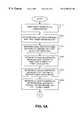
- the agentthen initiates a transfer to the other agent by keystroke action or by clicking on a button using a mouse, and by obtaining the telephone number of the other agent either through manual input or automatic generation by agent terminal 2300 [step 4110 ] (FIG. 4 A).
- Agent terminal 2300transmits the transfer command over the data connection to local CTI server 2320 [step 4120 ].
- Local CTI server 2320receives the command and, in turn, relays it along with the CALLID assigned to the call by network level switch 2100 , to network CTI server 2120 , indicating the need for transfer/conference service [step 4130 ].
- network CTI server 2120sends a command to network level switch 2100 requesting control of the call with the indicated CALLID [step 4140 ].
- network level switch 2100responds positively and gives network CTI server 2120 control of the call [step 4150 ].
- network CTI server 2120instructs the network level switch 2100 to obtain a three port conference circuit and to bridge the voice facilities to customer telephone 2200 and agent terminal 2300 into this circuit [step 4160 ].
- a three port conference circuitis a conventional device that allows three parties to converse simultaneously.
- Network CTI server 2120also supplies network level switch 2100 with a DN for a terminating switch, such as local switch 2410 , that is connected to an agent with the skills required by the customer [step 4210 ] (FIG. 4 B), and instructs network level switch 2100 to set up a connection to this local switch [step 4220 ].
- Network level switch 2100adds this connection to the conference circuit.
- network level switch 2100maintains separate billing data, including the conversation time on this new call leg, for the connection to local switch 2410 [step 4230 ].
- network CTI server 2120transmits call context data, including data collected by the agent using agent terminal 2300 , such as the customer's credit card number, to local CTI server 2420 [step 4240 ].
- Network level switch 2100then routes the call to local switch 2410 via the PSTN [step 4250 ].
- the callreaches local switch 2410 , it establishes a data session with local CTI server 2420 [step 4310 ] (FIG. 4 C).
- Local switch 2410sends call information, including the calling and called numbers, to local CTI server 2420 [step 4320 ].
- Local CTI server 2420associates the call information with the call data from network CTI server 2120 [step 4330 ], and uses this information to populate agent terminal 2400 [step 4340 ].
- local switch 2410In addition to sending the call information to local CTI server 2420 , local switch 2410 connects agent terminal 2400 to the call [step 4350 ]. Once the agent answers, all three parties can converse [step 4360 ]. If desired, the initial connection can be set up so that the customer cannot hear, and the two agents can converse privately.
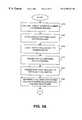
- the agent using agent terminal 2300goes on-hook and drops out of the conversation [step 5110 ] (FIG. 5 A).
- This eventpropagates through the PSTN to network level switch 2100 [step 5120 ] which, in turn, relays it to network CTI server 2120 [step 5130 ].
- Network CTI server 2120instructs network level switch 2100 to drop the voice facility between the switch and local switch 2310 [step 5140 ]. It also instructs network level switch 2100 to release the conference circuit and connect the voice facility from customer telephone 2200 directly to the voice facility to agent terminal 2400 [step 5150 ].
- Network CTI server 2120then instructs network level switch 2100 to produce a billing record for the first leg of the call [step 5160 ].
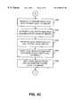
- Network level switch 2100produces a billing record for the call between customer telephone 2200 and agent terminal 2300 , reflecting the actual time that the customer and the agent conversed, and transmits it to billing system 2140 [step 5210 ] (FIG. 5 B).
- Network level switch 2100then ends the data session with network CTI server 2120 [step 5220 ].
- network level switch 2100produces the billing record for the first leg of the call, the agent, using agent terminal 2400 , services the customer call [step 5230 ]. When the service concludes [step 5240 ], network level switch 2100 releases all voice facilities [step 5250 ]. Finally, network level switch 2100 produces a second billing record, showing the actual time that customer telephone 2200 and agent terminal 2400 were connected, and transmits it to billing system 2140 [step 5260 ].
- FIG. 6is a diagram of an exemplary communications network in an alternative implementation consistent with the present invention.
- the diagram of FIG. 6is identical to the diagram of FIG. 2, except for the inclusion of Interactive Voice Response (IVR) unit 6100 and the removal of the data connections between network CTI server 2120 and local CTI servers 2320 and 2410 .
- IVRInteractive Voice Response
- IVR 6100includes a computer, such as a personal computer or a larger mainframe computer, with a voice connection to network level switch 2100 and a data connection, such as an Ethernet-equivalent data connection, to network CTI server 2120 .
- IVR 6100contains the ability to receive dual tone multi-frequency (DTMF) tones, to decipher a transfer telephone number from the received DTMF tones, and to send the transfer telephone number to network CTI server 2120 .
- DTMFdual tone multi-frequency
- FIGS. 3A-5Bdescribes an operation by which an agent initiates a call transfer request by sending call transfer information from agent terminal 2300 to network level switch 2100 via local CTI server 2320 and network CTI server 2120 .
- agent terminal 2300sends the call transfer information directly to network level switch 2100 via the PSTN.
- call set-upoccurs as previously described with regard to FIGS. 3A-3C.
- network CTI server 2120instructs network level switch 2100 to route the call, it also instructs the switch to monitor the connection to agent terminal 2300 for predetermined DTMF signals of at least 500 milliseconds in duration, such as “#” or “*” signals capable of being output from a conventional telephone.
- Network level switch 2100monitors for a signal of at least 500 milliseconds in duration to prevent conflicts with other voice processing and IVR systems that may be present in the network.
- FIGS. 7A and 7Bshow a flowchart of call transfer operations in the alternative implementation consistent with the present invention.
- the flowchart of FIGS. 7A and 7Bcorresponds to the flowchart of FIG. 4 A.
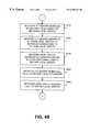
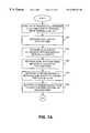
- agent operating agent terminal 2300determines that the call should be transferred to another agent, the agent depresses a predetermined DTMF key, such as the “#” or “*” key, for at least 500 milliseconds [step 7110 ] (FIG. 7 A). As a result, agent terminal 2300 transmits a corresponding DTMF signal to network level switch 2100 via local switch 2310 and the PSTN.
- a predetermined DTMF keysuch as the “#” or “*” key
- Network level switch 2100detects the DTMF signal [step 7120 ] and, in response, establishes a data session with network CTI server 2120 [step 7130 ]. Network level switch 2100 thereafter informs network CTI server 2120 that it detected the predetermined DTMF signal [step 7140 ].
- Network CTI server 2120interprets detection of the predetermined DTMF signal by the network level switch 2100 as a request to transfer a call. As a result, network CTI server 2120 instructs network level switch 2100 to establish a voice path between agent terminal 2300 and IVR 6100 [step 7150 ]. At this time, network CTI server 2120 may also instruct network level switch 2100 to connect customer telephone 2200 to IVR 6100 so that IVR 6100 can play music or announcements for the customer while the agent communicates with IVR 6100 .
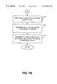
- network CTI server 2120instructs IVR 6100 to transmit a confirmation tone or announcement, informing the agent to enter the telephone number for the agent to which the call will be transferred [step 7160 ].
- the agentUpon hearing the confirmation tone or announcement, the agent enters the number using standard DTMF keying [step 7210 ] (FIG. 7 B).
- IVR 6100relays the telephone number to network CTI server 2120 [step 7220 ].
- network CTI server 2120instructs network level switch 2100 to obtain a three port conference circuit, and to bridge the voice facilities to customer telephone 2200 and agent terminal 2300 into this circuit [step 7230 ]. Processing then proceeds as described above beginning with step 4210 in FIG. 4 B.
- FIG. 2shows separate tandem and network level switches, but the tandem level switch can execute the advanced call control software and perform the operations described above with respect to the network level switch.
- FIG. 2also shows that the local switches connect to the tandem and network level switches via the PSTN, but private facilities could be used instead.
Landscapes
- Engineering & Computer Science (AREA)
- Signal Processing (AREA)
- Computer Networks & Wireless Communication (AREA)
- Multimedia (AREA)
- Meter Arrangements (AREA)
- Telephonic Communication Services (AREA)
Abstract
Description
Claims (62)
Priority Applications (1)
| Application Number | Priority Date | Filing Date | Title |
|---|---|---|---|
| US09/114,069US6298127B1 (en) | 1998-07-13 | 1998-07-13 | Call transfer and conference with separate billing records per leg |
Applications Claiming Priority (1)
| Application Number | Priority Date | Filing Date | Title |
|---|---|---|---|
| US09/114,069US6298127B1 (en) | 1998-07-13 | 1998-07-13 | Call transfer and conference with separate billing records per leg |
Publications (1)
| Publication Number | Publication Date |
|---|---|
| US6298127B1true US6298127B1 (en) | 2001-10-02 |
Family
ID=22353201
Family Applications (1)
| Application Number | Title | Priority Date | Filing Date |
|---|---|---|---|
| US09/114,069Expired - LifetimeUS6298127B1 (en) | 1998-07-13 | 1998-07-13 | Call transfer and conference with separate billing records per leg |
Country Status (1)
| Country | Link |
|---|---|
| US (1) | US6298127B1 (en) |
Cited By (26)
| Publication number | Priority date | Publication date | Assignee | Title |
|---|---|---|---|---|
| US20030165222A1 (en)* | 2000-05-25 | 2003-09-04 | Jari Syrjala | Arranging subscriber billing in telecommunication system |
| US20040101117A1 (en)* | 2000-12-22 | 2004-05-27 | Juha-Pekka Koskinen | Charging in a communication system |
| US20040236686A1 (en)* | 2001-08-27 | 2004-11-25 | Bernhard Bohmer | Method for billing for a communication service |
| WO2004079979A3 (en)* | 2003-03-04 | 2005-01-06 | Worldcom Inc | Method and system for providing network interactive voice response with intelligent call routing integration |
| US20050025127A1 (en)* | 2003-07-31 | 2005-02-03 | Strathmeyer Carl R. | Method and apparatus for communication web services |
| US6859529B2 (en) | 2000-04-12 | 2005-02-22 | Austin Logistics Incorporated | Method and system for self-service scheduling of inbound inquiries |
| US20050047395A1 (en)* | 2003-08-29 | 2005-03-03 | Microsoft Corporation | System and method for enhanced computer telephony integration and interaction |
| US20060023859A1 (en)* | 2004-07-30 | 2006-02-02 | Crockett Susanne M | Subscriber alterable call transfer service |
| US20060062364A1 (en)* | 2004-09-15 | 2006-03-23 | Crockett Susanne M | System and method for billing telephone calls |
| US7054434B2 (en) | 2001-07-09 | 2006-05-30 | Austin Logistics Incorporated | System and method for common account based routing of contact records |
| US7103173B2 (en) | 2001-07-09 | 2006-09-05 | Austin Logistics Incorporated | System and method for preemptive goals based routing of contact records |
| US7142662B2 (en) | 2000-07-11 | 2006-11-28 | Austin Logistics Incorporated | Method and system for distributing outbound telephone calls |
| US20070064912A1 (en)* | 2005-09-13 | 2007-03-22 | International Business Machines Corporation | Call routing between shared service centers |
| US7272217B1 (en)* | 1998-12-16 | 2007-09-18 | At&T Corp. | Telecommunications call time slicing system and method |
| US7502460B2 (en) | 2006-11-20 | 2009-03-10 | Austin Logistics Incorporated | Method and system for distributing outbound telephone calls |
| US7715546B2 (en) | 2001-07-09 | 2010-05-11 | Austin Logistics Incorporated | System and method for updating contact records |
| US7751384B1 (en)* | 2003-06-03 | 2010-07-06 | Sprint Spectrum L.P. | Method and system for identifying calls |
| US7769159B1 (en) | 2003-06-03 | 2010-08-03 | Sprint Spectrum L.P. | Method and system for identifying calls |
| US20130089193A1 (en)* | 2010-03-31 | 2013-04-11 | Itxc Ip Holdings S.A.R.L. | System, method, and computer-readable storage medium for telecom billing outsourcing |
| US8443179B2 (en) | 2003-09-30 | 2013-05-14 | Microsoft Corporation | Method and system for unified audio control on a personal computer |
| US8635554B2 (en) | 2003-05-20 | 2014-01-21 | Microsoft Corporation | Enhanced telephony computer user interface allowing user interaction and control of a telephone using a personal computer |
| US8731162B1 (en)* | 2013-03-15 | 2014-05-20 | Vonage Network, Llc | Systems and methods for matching call detail records for the same communication generated by different elements of an IP telephony system |
| US8938062B2 (en) | 1995-12-11 | 2015-01-20 | Comcast Ip Holdings I, Llc | Method for accessing service resource items that are for use in a telecommunications system |
| US9191505B2 (en) | 2009-05-28 | 2015-11-17 | Comcast Cable Communications, Llc | Stateful home phone service |
| US9420117B2 (en) | 2013-03-15 | 2016-08-16 | Vonage America Inc. | Systems and methods for matching call detail records for the same communication generated by different elements of an IP telephony system |
| US9549070B2 (en)* | 2015-02-12 | 2017-01-17 | Avaya Inc. | System and method for compatibility-based team formation |
Citations (5)
| Publication number | Priority date | Publication date | Assignee | Title |
|---|---|---|---|---|
| US5517560A (en)* | 1992-12-21 | 1996-05-14 | At&T Corp. | Call billing and measurement methods for redirected calls |
| US5617471A (en)* | 1995-05-25 | 1997-04-01 | Rogers; Wesley D. | Telecommunications system for transferring a telephone call |
| US5684867A (en)* | 1994-11-03 | 1997-11-04 | Lucent Technologies Inc. | Remote data access for operator assistance calls |
| US5715307A (en)* | 1994-09-26 | 1998-02-03 | Rockwell International Corporation | Integrated voice and business transaction reporting for telephone call centers |
| US5926535A (en)* | 1996-08-05 | 1999-07-20 | International Business Machines Corporation | Third party call control |
- 1998
- 1998-07-13USUS09/114,069patent/US6298127B1/ennot_activeExpired - Lifetime
Patent Citations (5)
| Publication number | Priority date | Publication date | Assignee | Title |
|---|---|---|---|---|
| US5517560A (en)* | 1992-12-21 | 1996-05-14 | At&T Corp. | Call billing and measurement methods for redirected calls |
| US5715307A (en)* | 1994-09-26 | 1998-02-03 | Rockwell International Corporation | Integrated voice and business transaction reporting for telephone call centers |
| US5684867A (en)* | 1994-11-03 | 1997-11-04 | Lucent Technologies Inc. | Remote data access for operator assistance calls |
| US5617471A (en)* | 1995-05-25 | 1997-04-01 | Rogers; Wesley D. | Telecommunications system for transferring a telephone call |
| US5926535A (en)* | 1996-08-05 | 1999-07-20 | International Business Machines Corporation | Third party call control |
Cited By (51)
| Publication number | Priority date | Publication date | Assignee | Title |
|---|---|---|---|---|
| US8938062B2 (en) | 1995-12-11 | 2015-01-20 | Comcast Ip Holdings I, Llc | Method for accessing service resource items that are for use in a telecommunications system |
| US20070291919A1 (en)* | 1998-12-16 | 2007-12-20 | Rao Kocharlakota | Telecommunications call time slicing system and method |
| US7995724B2 (en) | 1998-12-16 | 2011-08-09 | At&T Intellectual Property Ii, L.P. | Telecommunications call time slicing system and method |
| US7272217B1 (en)* | 1998-12-16 | 2007-09-18 | At&T Corp. | Telecommunications call time slicing system and method |
| US6859529B2 (en) | 2000-04-12 | 2005-02-22 | Austin Logistics Incorporated | Method and system for self-service scheduling of inbound inquiries |
| US8009816B2 (en)* | 2000-05-25 | 2011-08-30 | Nokia Corporation | Arranging subscriber billing in telecommunication system |
| US20030165222A1 (en)* | 2000-05-25 | 2003-09-04 | Jari Syrjala | Arranging subscriber billing in telecommunication system |
| US7142662B2 (en) | 2000-07-11 | 2006-11-28 | Austin Logistics Incorporated | Method and system for distributing outbound telephone calls |
| USRE46478E1 (en) | 2000-07-11 | 2017-07-11 | Noble Systems Corporation | System and method for preemptive goals based routing of contact records |
| USRE46467E1 (en) | 2000-07-11 | 2017-07-04 | Noble Systems Corporation | Method and system for distributing outbound telephone calls |
| USRE46420E1 (en) | 2000-07-11 | 2017-05-30 | Noble Systems Corporation | Method and system for distributing outbound telephone calls |
| US7239692B2 (en) | 2000-07-11 | 2007-07-03 | Austin Logistics Incorporated | Method and system for distributing outbound telephone calls |
| US7725097B2 (en) | 2000-12-22 | 2010-05-25 | Nokia Corporation | Charging in a communication system |
| US20060234674A1 (en)* | 2000-12-22 | 2006-10-19 | Nokia Corporation | Charging in a communication system |
| US7058165B2 (en)* | 2000-12-22 | 2006-06-06 | Nokia Corporation | Charging in a communication system |
| US20040101117A1 (en)* | 2000-12-22 | 2004-05-27 | Juha-Pekka Koskinen | Charging in a communication system |
| US7158629B2 (en) | 2001-07-09 | 2007-01-02 | Austin Logistics Incorporated | System and method for preemptive goals based routing of contact records |
| US7103173B2 (en) | 2001-07-09 | 2006-09-05 | Austin Logistics Incorporated | System and method for preemptive goals based routing of contact records |
| US7054434B2 (en) | 2001-07-09 | 2006-05-30 | Austin Logistics Incorporated | System and method for common account based routing of contact records |
| USRE44979E1 (en) | 2001-07-09 | 2014-07-01 | Noble Systems Corporation | System and method for common account based routing of contact records |
| US7715546B2 (en) | 2001-07-09 | 2010-05-11 | Austin Logistics Incorporated | System and method for updating contact records |
| US8175258B2 (en) | 2001-07-09 | 2012-05-08 | Austin Logistics Incorporated | System and method for common account based routing of contact records |
| US20040236686A1 (en)* | 2001-08-27 | 2004-11-25 | Bernhard Bohmer | Method for billing for a communication service |
| US7221753B2 (en)* | 2003-03-04 | 2007-05-22 | Verizon Business Global Llc | Method and system for providing network interactive voice response with intelligent call routing integration |
| WO2004079979A3 (en)* | 2003-03-04 | 2005-01-06 | Worldcom Inc | Method and system for providing network interactive voice response with intelligent call routing integration |
| US8694915B2 (en) | 2003-05-20 | 2014-04-08 | Microsoft Corporation | Enhanced telephony computer user interface allowing user interaction and control of a telephone using a personal computer |
| US9392043B2 (en) | 2003-05-20 | 2016-07-12 | Microsoft Technology Licensing, Llc | Enhanced telephony computer user interface allowing user interaction and control of a telephone using a personal computer |
| US8635554B2 (en) | 2003-05-20 | 2014-01-21 | Microsoft Corporation | Enhanced telephony computer user interface allowing user interaction and control of a telephone using a personal computer |
| US7751384B1 (en)* | 2003-06-03 | 2010-07-06 | Sprint Spectrum L.P. | Method and system for identifying calls |
| US7769159B1 (en) | 2003-06-03 | 2010-08-03 | Sprint Spectrum L.P. | Method and system for identifying calls |
| US20050025127A1 (en)* | 2003-07-31 | 2005-02-03 | Strathmeyer Carl R. | Method and apparatus for communication web services |
| US20050047395A1 (en)* | 2003-08-29 | 2005-03-03 | Microsoft Corporation | System and method for enhanced computer telephony integration and interaction |
| US7697506B2 (en)* | 2003-08-29 | 2010-04-13 | Microsoft Corporation | System and method for enhanced computer telephony integration and interaction |
| US8443179B2 (en) | 2003-09-30 | 2013-05-14 | Microsoft Corporation | Method and system for unified audio control on a personal computer |
| US8644481B2 (en) | 2003-09-30 | 2014-02-04 | Microsoft Corporation | Method and system for unified audio control on a personal computer |
| US7965829B2 (en) | 2004-07-30 | 2011-06-21 | At&T Intellectual Property I, L.P. | Subscriber alterable call transfer service |
| US20060023859A1 (en)* | 2004-07-30 | 2006-02-02 | Crockett Susanne M | Subscriber alterable call transfer service |
| US7813487B2 (en)* | 2004-09-15 | 2010-10-12 | At&T Intellectual Property I, L.P. | System and method for billing telephone calls |
| US20060062364A1 (en)* | 2004-09-15 | 2006-03-23 | Crockett Susanne M | System and method for billing telephone calls |
| US8774389B2 (en)* | 2005-09-13 | 2014-07-08 | International Business Machines Corporation | Call routing between shared service centers |
| US20070064912A1 (en)* | 2005-09-13 | 2007-03-22 | International Business Machines Corporation | Call routing between shared service centers |
| US7502460B2 (en) | 2006-11-20 | 2009-03-10 | Austin Logistics Incorporated | Method and system for distributing outbound telephone calls |
| US9191505B2 (en) | 2009-05-28 | 2015-11-17 | Comcast Cable Communications, Llc | Stateful home phone service |
| US9137387B2 (en) | 2010-03-31 | 2015-09-15 | Itxc Ip Holdings S.A.R.L. | System, method, and computer-readable storage medium for telecom billing outsourcing |
| US9001986B2 (en)* | 2010-03-31 | 2015-04-07 | Itxc Ip Holdings S.A.R.L. | System, method, and computer-readable storage medium for telecom billing outsourcing |
| US20140185782A1 (en)* | 2010-03-31 | 2014-07-03 | Itxc Ip Holdings S.A.R.L. | System, method, and computer-readable storage medium for telecom billing outsourcing |
| US8731160B2 (en)* | 2010-03-31 | 2014-05-20 | Itxc Ip Holdings S.A.R.L. | System, method, and computer-readable storage medium for telecom billing outsourcing |
| US20130089193A1 (en)* | 2010-03-31 | 2013-04-11 | Itxc Ip Holdings S.A.R.L. | System, method, and computer-readable storage medium for telecom billing outsourcing |
| US9420117B2 (en) | 2013-03-15 | 2016-08-16 | Vonage America Inc. | Systems and methods for matching call detail records for the same communication generated by different elements of an IP telephony system |
| US8731162B1 (en)* | 2013-03-15 | 2014-05-20 | Vonage Network, Llc | Systems and methods for matching call detail records for the same communication generated by different elements of an IP telephony system |
| US9549070B2 (en)* | 2015-02-12 | 2017-01-17 | Avaya Inc. | System and method for compatibility-based team formation |
Similar Documents
| Publication | Publication Date | Title |
|---|---|---|
| US6298127B1 (en) | Call transfer and conference with separate billing records per leg | |
| US6044142A (en) | Method and arrangement for integrating intelligent network services with operator assisted services | |
| US7020261B2 (en) | Method for providing enhanced directory assistance upon command using out-of-band signaling | |
| US5499289A (en) | Systems, methods and articles of manufacture for performing distributed telecommunications | |
| US5432845A (en) | Post answer telephone call redirection or rerouting | |
| KR100249578B1 (en) | System provides personalized phone call features | |
| JP2927461B2 (en) | More efficient call processing for operator assistant calls | |
| JP4865123B2 (en) | Multi-party telephone conferencing system and method for use in an automated communication system for establishing a telephone conference call | |
| EP0908047B1 (en) | Methods and apparatus for implementing a network call center | |
| US5459779A (en) | Method for switching telephone calls to information service providers | |
| JP2603366B2 (en) | Method and apparatus for providing ANI information and / or DNIS information | |
| JP2611018B2 (en) | Automatic call distribution device and automatic call distribution method | |
| US7526077B2 (en) | Call hold signaling | |
| US6829243B1 (en) | Directory assistance for IP telephone subscribers | |
| US5659605A (en) | Method and apparatus for providing soft dial tone using office equipment designators | |
| US6947527B2 (en) | Method and apparatus that provides a reusable voice path in addition to release link functionality for use with a platform having a voice activated front end | |
| EP1062820B1 (en) | Service in a communications network | |
| US5502756A (en) | Remote test call unit and service | |
| US7831031B2 (en) | Method and system for operator services automation using an operator services switch | |
| EP0321498B1 (en) | Directory assistance call processing and non-supervisory signal monitoring arrangements | |
| US5764735A (en) | Device for multimedia communication | |
| EP1071266A1 (en) | Telephone recording systems | |
| US7933398B1 (en) | System and method for call bridging in a call center using a virtual private network | |
| US6611585B1 (en) | Method and apparatus for intelligent release link trunk | |
| US7046776B1 (en) | Method for converting a three-party telecommunications connection which is switched via the public communications network into a two-party telecommunications connection |
Legal Events
| Date | Code | Title | Description |
|---|---|---|---|
| AS | Assignment | Owner name:NORTHERN TELECOM LIMITED, CANADA Free format text:ASSIGNMENT OF ASSIGNORS INTEREST;ASSIGNOR:PETRUNKA, ROBERT W;REEL/FRAME:009335/0930 Effective date:19980702 | |
| AS | Assignment | Owner name:NORTEL NETWORKS CORPORATION, CANADA Free format text:CHANGE OF NAME;ASSIGNOR:NORTHERN TELECOM LIMITED;REEL/FRAME:010567/0001 Effective date:19990429 | |
| AS | Assignment | Owner name:NORTEL NETWORKS LIMITED, CANADA Free format text:CHANGE OF NAME;ASSIGNOR:NORTEL NETWORKS CORPORATION;REEL/FRAME:011195/0706 Effective date:20000830 Owner name:NORTEL NETWORKS LIMITED,CANADA Free format text:CHANGE OF NAME;ASSIGNOR:NORTEL NETWORKS CORPORATION;REEL/FRAME:011195/0706 Effective date:20000830 | |
| STCF | Information on status: patent grant | Free format text:PATENTED CASE | |
| FPAY | Fee payment | Year of fee payment:4 | |
| FPAY | Fee payment | Year of fee payment:8 | |
| FEPP | Fee payment procedure | Free format text:PAYOR NUMBER ASSIGNED (ORIGINAL EVENT CODE: ASPN); ENTITY STATUS OF PATENT OWNER: LARGE ENTITY | |
| AS | Assignment | Owner name:CITIBANK, N.A., AS ADMINISTRATIVE AGENT,NEW YORK Free format text:SECURITY AGREEMENT;ASSIGNOR:AVAYA INC.;REEL/FRAME:023892/0500 Effective date:20100129 Owner name:CITIBANK, N.A., AS ADMINISTRATIVE AGENT, NEW YORK Free format text:SECURITY AGREEMENT;ASSIGNOR:AVAYA INC.;REEL/FRAME:023892/0500 Effective date:20100129 | |
| AS | Assignment | Owner name:CITICORP USA, INC., AS ADMINISTRATIVE AGENT, NEW YORK Free format text:SECURITY AGREEMENT;ASSIGNOR:AVAYA INC.;REEL/FRAME:023905/0001 Effective date:20100129 Owner name:CITICORP USA, INC., AS ADMINISTRATIVE AGENT,NEW YO Free format text:SECURITY AGREEMENT;ASSIGNOR:AVAYA INC.;REEL/FRAME:023905/0001 Effective date:20100129 Owner name:CITICORP USA, INC., AS ADMINISTRATIVE AGENT, NEW Y Free format text:SECURITY AGREEMENT;ASSIGNOR:AVAYA INC.;REEL/FRAME:023905/0001 Effective date:20100129 | |
| AS | Assignment | Owner name:AVAYA INC.,NEW JERSEY Free format text:ASSIGNMENT OF ASSIGNORS INTEREST;ASSIGNOR:NORTEL NETWORKS LIMITED;REEL/FRAME:023998/0878 Effective date:20091218 Owner name:AVAYA INC., NEW JERSEY Free format text:ASSIGNMENT OF ASSIGNORS INTEREST;ASSIGNOR:NORTEL NETWORKS LIMITED;REEL/FRAME:023998/0878 Effective date:20091218 | |
| AS | Assignment | Owner name:BANK OF NEW YORK MELLON TRUST, NA, AS NOTES COLLATERAL AGENT, THE, PENNSYLVANIA Free format text:SECURITY AGREEMENT;ASSIGNOR:AVAYA INC., A DELAWARE CORPORATION;REEL/FRAME:025863/0535 Effective date:20110211 Owner name:BANK OF NEW YORK MELLON TRUST, NA, AS NOTES COLLAT Free format text:SECURITY AGREEMENT;ASSIGNOR:AVAYA INC., A DELAWARE CORPORATION;REEL/FRAME:025863/0535 Effective date:20110211 | |
| FPAY | Fee payment | Year of fee payment:12 | |
| AS | Assignment | Owner name:BANK OF NEW YORK MELLON TRUST COMPANY, N.A., THE, PENNSYLVANIA Free format text:SECURITY AGREEMENT;ASSIGNOR:AVAYA, INC.;REEL/FRAME:030083/0639 Effective date:20130307 Owner name:BANK OF NEW YORK MELLON TRUST COMPANY, N.A., THE, Free format text:SECURITY AGREEMENT;ASSIGNOR:AVAYA, INC.;REEL/FRAME:030083/0639 Effective date:20130307 | |
| AS | Assignment | Owner name:CITIBANK, N.A., AS ADMINISTRATIVE AGENT, NEW YORK Free format text:SECURITY INTEREST;ASSIGNORS:AVAYA INC.;AVAYA INTEGRATED CABINET SOLUTIONS INC.;OCTEL COMMUNICATIONS CORPORATION;AND OTHERS;REEL/FRAME:041576/0001 Effective date:20170124 | |
| AS | Assignment | Owner name:OCTEL COMMUNICATIONS LLC (FORMERLY KNOWN AS OCTEL COMMUNICATIONS CORPORATION), CALIFORNIA Free format text:BANKRUPTCY COURT ORDER RELEASING ALL LIENS INCLUDING THE SECURITY INTEREST RECORDED AT REEL/FRAME 041576/0001;ASSIGNOR:CITIBANK, N.A.;REEL/FRAME:044893/0531 Effective date:20171128 Owner name:AVAYA INTEGRATED CABINET SOLUTIONS INC., CALIFORNIA Free format text:BANKRUPTCY COURT ORDER RELEASING ALL LIENS INCLUDING THE SECURITY INTEREST RECORDED AT REEL/FRAME 041576/0001;ASSIGNOR:CITIBANK, N.A.;REEL/FRAME:044893/0531 Effective date:20171128 Owner name:AVAYA INC., CALIFORNIA Free format text:BANKRUPTCY COURT ORDER RELEASING ALL LIENS INCLUDING THE SECURITY INTEREST RECORDED AT REEL/FRAME 023892/0500;ASSIGNOR:CITIBANK, N.A.;REEL/FRAME:044891/0564 Effective date:20171128 Owner name:AVAYA INC., CALIFORNIA Free format text:BANKRUPTCY COURT ORDER RELEASING ALL LIENS INCLUDING THE SECURITY INTEREST RECORDED AT REEL/FRAME 025863/0535;ASSIGNOR:THE BANK OF NEW YORK MELLON TRUST, NA;REEL/FRAME:044892/0001 Effective date:20171128 Owner name:AVAYA INC., CALIFORNIA Free format text:BANKRUPTCY COURT ORDER RELEASING ALL LIENS INCLUDING THE SECURITY INTEREST RECORDED AT REEL/FRAME 041576/0001;ASSIGNOR:CITIBANK, N.A.;REEL/FRAME:044893/0531 Effective date:20171128 Owner name:VPNET TECHNOLOGIES, INC., CALIFORNIA Free format text:BANKRUPTCY COURT ORDER RELEASING ALL LIENS INCLUDING THE SECURITY INTEREST RECORDED AT REEL/FRAME 041576/0001;ASSIGNOR:CITIBANK, N.A.;REEL/FRAME:044893/0531 Effective date:20171128 Owner name:OCTEL COMMUNICATIONS LLC (FORMERLY KNOWN AS OCTEL Free format text:BANKRUPTCY COURT ORDER RELEASING ALL LIENS INCLUDING THE SECURITY INTEREST RECORDED AT REEL/FRAME 041576/0001;ASSIGNOR:CITIBANK, N.A.;REEL/FRAME:044893/0531 Effective date:20171128 Owner name:AVAYA INTEGRATED CABINET SOLUTIONS INC., CALIFORNI Free format text:BANKRUPTCY COURT ORDER RELEASING ALL LIENS INCLUDING THE SECURITY INTEREST RECORDED AT REEL/FRAME 041576/0001;ASSIGNOR:CITIBANK, N.A.;REEL/FRAME:044893/0531 Effective date:20171128 Owner name:AVAYA INC., CALIFORNIA Free format text:BANKRUPTCY COURT ORDER RELEASING ALL LIENS INCLUDING THE SECURITY INTEREST RECORDED AT REEL/FRAME 030083/0639;ASSIGNOR:THE BANK OF NEW YORK MELLON TRUST COMPANY, N.A.;REEL/FRAME:045012/0666 Effective date:20171128 | |
| AS | Assignment | Owner name:GOLDMAN SACHS BANK USA, AS COLLATERAL AGENT, NEW YORK Free format text:SECURITY INTEREST;ASSIGNORS:AVAYA INC.;AVAYA INTEGRATED CABINET SOLUTIONS LLC;OCTEL COMMUNICATIONS LLC;AND OTHERS;REEL/FRAME:045034/0001 Effective date:20171215 Owner name:GOLDMAN SACHS BANK USA, AS COLLATERAL AGENT, NEW Y Free format text:SECURITY INTEREST;ASSIGNORS:AVAYA INC.;AVAYA INTEGRATED CABINET SOLUTIONS LLC;OCTEL COMMUNICATIONS LLC;AND OTHERS;REEL/FRAME:045034/0001 Effective date:20171215 | |
| AS | Assignment | Owner name:SIERRA HOLDINGS CORP., NEW JERSEY Free format text:RELEASE BY SECURED PARTY;ASSIGNOR:CITICORP USA, INC.;REEL/FRAME:045045/0564 Effective date:20171215 Owner name:AVAYA, INC., CALIFORNIA Free format text:RELEASE BY SECURED PARTY;ASSIGNOR:CITICORP USA, INC.;REEL/FRAME:045045/0564 Effective date:20171215 | |
| AS | Assignment | Owner name:CITIBANK, N.A., AS COLLATERAL AGENT, NEW YORK Free format text:SECURITY INTEREST;ASSIGNORS:AVAYA INC.;AVAYA INTEGRATED CABINET SOLUTIONS LLC;OCTEL COMMUNICATIONS LLC;AND OTHERS;REEL/FRAME:045124/0026 Effective date:20171215 | |
| AS | Assignment | Owner name:AVAYA INTEGRATED CABINET SOLUTIONS LLC, NEW JERSEY Free format text:RELEASE OF SECURITY INTEREST IN PATENTS AT REEL 45124/FRAME 0026;ASSIGNOR:CITIBANK, N.A., AS COLLATERAL AGENT;REEL/FRAME:063457/0001 Effective date:20230403 Owner name:AVAYA MANAGEMENT L.P., NEW JERSEY Free format text:RELEASE OF SECURITY INTEREST IN PATENTS AT REEL 45124/FRAME 0026;ASSIGNOR:CITIBANK, N.A., AS COLLATERAL AGENT;REEL/FRAME:063457/0001 Effective date:20230403 Owner name:AVAYA INC., NEW JERSEY Free format text:RELEASE OF SECURITY INTEREST IN PATENTS AT REEL 45124/FRAME 0026;ASSIGNOR:CITIBANK, N.A., AS COLLATERAL AGENT;REEL/FRAME:063457/0001 Effective date:20230403 Owner name:AVAYA HOLDINGS CORP., NEW JERSEY Free format text:RELEASE OF SECURITY INTEREST IN PATENTS AT REEL 45124/FRAME 0026;ASSIGNOR:CITIBANK, N.A., AS COLLATERAL AGENT;REEL/FRAME:063457/0001 Effective date:20230403 | |
| AS | Assignment | Owner name:AVAYA MANAGEMENT L.P., NEW JERSEY Free format text:RELEASE OF SECURITY INTEREST IN PATENTS (REEL/FRAME 045034/0001);ASSIGNOR:GOLDMAN SACHS BANK USA., AS COLLATERAL AGENT;REEL/FRAME:063779/0622 Effective date:20230501 Owner name:CAAS TECHNOLOGIES, LLC, NEW JERSEY Free format text:RELEASE OF SECURITY INTEREST IN PATENTS (REEL/FRAME 045034/0001);ASSIGNOR:GOLDMAN SACHS BANK USA., AS COLLATERAL AGENT;REEL/FRAME:063779/0622 Effective date:20230501 Owner name:HYPERQUALITY II, LLC, NEW JERSEY Free format text:RELEASE OF SECURITY INTEREST IN PATENTS (REEL/FRAME 045034/0001);ASSIGNOR:GOLDMAN SACHS BANK USA., AS COLLATERAL AGENT;REEL/FRAME:063779/0622 Effective date:20230501 Owner name:HYPERQUALITY, INC., NEW JERSEY Free format text:RELEASE OF SECURITY INTEREST IN PATENTS (REEL/FRAME 045034/0001);ASSIGNOR:GOLDMAN SACHS BANK USA., AS COLLATERAL AGENT;REEL/FRAME:063779/0622 Effective date:20230501 Owner name:ZANG, INC. (FORMER NAME OF AVAYA CLOUD INC.), NEW JERSEY Free format text:RELEASE OF SECURITY INTEREST IN PATENTS (REEL/FRAME 045034/0001);ASSIGNOR:GOLDMAN SACHS BANK USA., AS COLLATERAL AGENT;REEL/FRAME:063779/0622 Effective date:20230501 Owner name:VPNET TECHNOLOGIES, INC., NEW JERSEY Free format text:RELEASE OF SECURITY INTEREST IN PATENTS (REEL/FRAME 045034/0001);ASSIGNOR:GOLDMAN SACHS BANK USA., AS COLLATERAL AGENT;REEL/FRAME:063779/0622 Effective date:20230501 Owner name:OCTEL COMMUNICATIONS LLC, NEW JERSEY Free format text:RELEASE OF SECURITY INTEREST IN PATENTS (REEL/FRAME 045034/0001);ASSIGNOR:GOLDMAN SACHS BANK USA., AS COLLATERAL AGENT;REEL/FRAME:063779/0622 Effective date:20230501 Owner name:AVAYA INTEGRATED CABINET SOLUTIONS LLC, NEW JERSEY Free format text:RELEASE OF SECURITY INTEREST IN PATENTS (REEL/FRAME 045034/0001);ASSIGNOR:GOLDMAN SACHS BANK USA., AS COLLATERAL AGENT;REEL/FRAME:063779/0622 Effective date:20230501 Owner name:INTELLISIST, INC., NEW JERSEY Free format text:RELEASE OF SECURITY INTEREST IN PATENTS (REEL/FRAME 045034/0001);ASSIGNOR:GOLDMAN SACHS BANK USA., AS COLLATERAL AGENT;REEL/FRAME:063779/0622 Effective date:20230501 Owner name:AVAYA INC., NEW JERSEY Free format text:RELEASE OF SECURITY INTEREST IN PATENTS (REEL/FRAME 045034/0001);ASSIGNOR:GOLDMAN SACHS BANK USA., AS COLLATERAL AGENT;REEL/FRAME:063779/0622 Effective date:20230501 |