US6298100B1 - Phase error estimation method for a demodulator in an HDTV receiver - Google Patents
Phase error estimation method for a demodulator in an HDTV receiverDownload PDFInfo
- Publication number
- US6298100B1 US6298100B1US09/427,315US42731599AUS6298100B1US 6298100 B1US6298100 B1US 6298100B1US 42731599 AUS42731599 AUS 42731599AUS 6298100 B1US6298100 B1US 6298100B1
- Authority
- US
- United States
- Prior art keywords
- sync
- value
- signal
- component
- pilot
- Prior art date
- Legal status (The legal status is an assumption and is not a legal conclusion. Google has not performed a legal analysis and makes no representation as to the accuracy of the status listed.)
- Expired - Lifetime
Links
- 238000000034methodMethods0.000titleclaimsdescription17
- 238000012545processingMethods0.000claimsabstractdescription6
- 230000004044responseEffects0.000claimsdescription7
- 238000011084recoveryMethods0.000abstractdescription19
- 230000014509gene expressionEffects0.000description7
- 238000012937correctionMethods0.000description3
- 238000010586diagramMethods0.000description3
- 230000000694effectsEffects0.000description3
- 230000006870functionEffects0.000description3
- 230000010363phase shiftEffects0.000description3
- 238000005070samplingMethods0.000description3
- 238000001228spectrumMethods0.000description3
- 230000005540biological transmissionEffects0.000description2
- 238000013461designMethods0.000description2
- 238000001914filtrationMethods0.000description2
- 230000001172regenerating effectEffects0.000description2
- 230000003252repetitive effectEffects0.000description2
- 230000001360synchronised effectEffects0.000description2
- 238000012549trainingMethods0.000description2
- 230000003044adaptive effectEffects0.000description1
- 238000013459approachMethods0.000description1
- 238000004364calculation methodMethods0.000description1
- 239000000470constituentSubstances0.000description1
- 230000002596correlated effectEffects0.000description1
- 238000005314correlation functionMethods0.000description1
- 230000000875corresponding effectEffects0.000description1
- 230000001419dependent effectEffects0.000description1
- 238000001514detection methodMethods0.000description1
- 230000001747exhibiting effectEffects0.000description1
- 238000010606normalizationMethods0.000description1
- 230000008054signal transmissionEffects0.000description1
Images


Classifications
- H—ELECTRICITY
- H04—ELECTRIC COMMUNICATION TECHNIQUE
- H04N—PICTORIAL COMMUNICATION, e.g. TELEVISION
- H04N7/00—Television systems
- H04N7/015—High-definition television systems
- H—ELECTRICITY
- H04—ELECTRIC COMMUNICATION TECHNIQUE
- H04L—TRANSMISSION OF DIGITAL INFORMATION, e.g. TELEGRAPHIC COMMUNICATION
- H04L27/00—Modulated-carrier systems
- H04L27/02—Amplitude-modulated carrier systems, e.g. using on-off keying; Single sideband or vestigial sideband modulation
- H04L27/06—Demodulator circuits; Receiver circuits
- H04L27/066—Carrier recovery circuits
- H—ELECTRICITY
- H04—ELECTRIC COMMUNICATION TECHNIQUE
- H04L—TRANSMISSION OF DIGITAL INFORMATION, e.g. TELEGRAPHIC COMMUNICATION
- H04L27/00—Modulated-carrier systems
- H04L27/0014—Carrier regulation
- H04L2027/0024—Carrier regulation at the receiver end
- H04L2027/0026—Correction of carrier offset
- H04L2027/003—Correction of carrier offset at baseband only
- H—ELECTRICITY
- H04—ELECTRIC COMMUNICATION TECHNIQUE
- H04L—TRANSMISSION OF DIGITAL INFORMATION, e.g. TELEGRAPHIC COMMUNICATION
- H04L27/00—Modulated-carrier systems
- H04L27/0014—Carrier regulation
- H04L2027/0024—Carrier regulation at the receiver end
- H04L2027/0026—Correction of carrier offset
- H04L2027/0036—Correction of carrier offset using a recovered symbol clock
- H—ELECTRICITY
- H04—ELECTRIC COMMUNICATION TECHNIQUE
- H04L—TRANSMISSION OF DIGITAL INFORMATION, e.g. TELEGRAPHIC COMMUNICATION
- H04L27/00—Modulated-carrier systems
- H04L27/0014—Carrier regulation
- H04L2027/0044—Control loops for carrier regulation
- H04L2027/0046—Open loops
- H—ELECTRICITY
- H04—ELECTRIC COMMUNICATION TECHNIQUE
- H04L—TRANSMISSION OF DIGITAL INFORMATION, e.g. TELEGRAPHIC COMMUNICATION
- H04L27/00—Modulated-carrier systems
- H04L27/0014—Carrier regulation
- H04L2027/0044—Control loops for carrier regulation
- H04L2027/0063—Elements of loops
- H04L2027/0067—Phase error detectors
Definitions
- This inventionconcerns a carrier recovery network for demodulating a high definition television signal, e.g., of the VSB-modulated type adopted for use in the United States.
- Timing recoveryis a process by which a receiver clock (timebase) is synchronized to a transmitter clock. This permits a received signal to be sampled at optimum points in time to reduce slicing errors associated with decision-directed processing of received symbol values.
- Carrier recoveryis a process by which a received RF signal, after being frequency down converted to a lower intermediate frequency passband (e.g., near baseband), is frequency shifted to baseband to permit recovery of the modulating baseband information.
- Adaptive channel equalizationis a process by which the effects of changing conditions and disturbances in the signal transmission channel are compensated for. This process typically employs filters that remove amplitude and phase distortions resulting from frequency dependent time variant characteristics of the transmission channel.
- a carrier recovery networkproduces a demodulated signal in response to a pilot carrier component of the received signal and a locally generated phase correction control signal representing an unwanted phase offset of the pilot signal transmitted with the main data signal.
- the control signalis a function of a correlation between a predetermined component of the received signal, and a reference value.
- control signalis produced by correlating a received sync component with both (a) a reference sync value, and (b) a Hilbert transform of the reference sync value.
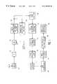
- FIG. 1is a block diagram of a portion of a high definition television (HDTV) receiver including apparatus according to the principles of the present invention.
- HDMIhigh definition television
- FIG. 2depicts a data frame format for a VSB modulated signal employing the ATSC high definition system in the United States.
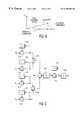
- FIG. 3shows details of a carrier recovery demodulator network in FIG. 1 in accordance with the present invention.
- FIG. 4is a diagram helpful in understanding the operation of the demodulator in FIG. 1 .
- FIG. 5shows additional details of a portion of the demodulator network in FIG. 1 .
- a terrestrial broadcast analog Input HDTV signalis processed by an input network 14 including RF tuning circuits and an intermediate frequency (IF) processor 16 including a tuner for producing an IF passband output signal, and appropriate automatic gain control (AGC) circuits.
- the received signalis a carrier suppressed 8-VSB modulated signal as proposed by the Grand Alliance and adopted as the ATSC terrestrial broadcast high definition television standard for use in the United States.
- Such a VSB signalis represented by a one-dimensional data symbol constellation wherein only one axis contains quantized data to be recovered by the receiver. To simplify the Figure, not shown are signals for clocking the illustrated functional blocks.
- each data framecomprises two fields with each field including 313 segments of 832 multilevel symbols.
- the first segment of each fieldis referred to as a field sync segment, and the remaining 312 segments are referred to as data segments.
- the data segmentstypically contain MPEG compatible data packets.
- Each data segmentcomprises a four-symbol segment sync component followed by 828 data symbols.
- Each field segmentincludes a four symbol segment sync character followed by a field sync component comprising a predetermined 511 symbol pseudorandom number (PN) sequence and three predetermined 63 symbol PN sequences, the middle one of which is inverted in successive fields.
- a VSB mode control signal(defining the VSB symbol constellation size) follows the last 63 PN sequence, which is followed by 96 reserved symbols and 12 symbols copied from the previous field.
- a small digital level(1.25) is added to every symbol (data and syncs) of the digital baseband data plus sync signal. This has the effect of adding a small in-phase pilot carrier component to the data signal.
- Digital addition of the pilot at basebandprovides a highly stable and accurate pilot. The frequency of the pilot is the same as the suppressed carrier frequency.
- the passband IF output signal from unit 16is converted to a digital symbol datastream by an analog to digital converter 19 .
- the output digital datastream from ADC 19is demodulated to baseband by a digital demodulator/carrier recovery network 22 . This is achieved by a phase locked loop in response to the pilot component in the received VSB datastream.
- Unit 22produces an output I-phase demodulated symbol datastream as described in greater detail with regard to FIG. 3 .
- ADC 19samples the input VSB symbol datastream in response to a sampling clock CLK.
- a segment sync and symbol clock recovery network 24Associated with ADC 19 and demodulator 22 is a segment sync and symbol clock recovery network 24 .
- Network 24recovers the repetitive data segment sync components of each data frame from the random data. The segment sync components are used to regenerate a properly phased sampling clock.
- Unit 28detects the data field sync component by comparing every received data segment with an ideal field reference signal stored in memory in the receiver.
- the field sync signalprovides a training signal for channel equalizer 34 .
- Co-channel NTSC interference detection and rejectionare performed by unit 30 .
- the signalis adaptively equalized by channel equalizer 34 which may operate in a combination of blind, training, and decision-directed modes.
- Equalizer 34may be of the type described in the Grand Alliance HDTV System Specification and in an article by W. Bretl et al., “VSB Modem Subsystem Design for Grand Alliance Digital Television Receivers,” IEEE Transactions on Consumer Electronics, August 1995.
- Equalizer 34also may be of the type described in copending U.S. patent application Ser. No. 102,885 of Shiue et al. filed Jun. 23, 1998.
- Equalizer 34compensates for channel distortions, but phase noise randomly rotates the symbol constellation.
- Phase tracking network 36removes any residual phase and gain noise present in the output signal from equalizer 34 .
- the phase corrected signalis then trellis decoded by unit 40 , de-interleaved by unit 42 , Reed-Solomon error corrected by unit 44 , and descrambled (de-randomized) by unit- 46 .
- a decoded datastreamis subjected to audio, video and display processing by unit 50 .
- Demodulation in unit 22is performed by a digital automatic phase control (APC) loop to achieve carrier recovery.
- the phase locked loopuses the pilot component as a reference for initial acquisition, and uses a conventional phase detector for phase acquisition.
- the pilot signalis embedded in the received datastream, which contains data exhibiting a random, noise-like pattern.
- the random datais essentially disregarded by the filtering action of the demodulator APC loop.
- the input signal to ADC 19is a near baseband signal with the center of the VSB frequency spectrum at 5.38 MHz and the pilot component situated at 2.69 MHz. In the demodulated datastream from unit 22 the pilot component has been frequency shifted down to DC.
- FIG. 3show details of digital demodulator 22 .
- Demodulator 22includes a first phase control network 320 , a second phase control network 350 , and a phase correction signal generator 360 . The operation of network 320 will be described first.
- the 8-VSB modulated digital symbol datastream from ADC 19containing the very low frequency pilot component, is applied to Hilbert filter 315 that separates the incoming IF sampled datastream into mutually quadrature phased components “I” (in phase) and “Q” (quadrature phase).
- the I and Q componentsare rotated to baseband using complex multiplier 324 in an automatic phase control (APC) loop.
- APCautomatic phase control
- the output of multiplier 324is a complex baseband signal that is further phase adjusted by network 350 , as will be discussed, to produce a final phase corrected demodulated output from unit 350 .
- the output I datastream from multiplier 324is used to extract the pilot component of the received datastream.
- the output Q datastream from multiplier 324is used to extract the phase of the received signal.
- the Q signalis filtered by an automatic frequency control (AFC) filter 336 .
- AFCautomatic frequency control
- High frequency data(as well as noise and interference) are largely rejected by the AFC filter, leaving only the pilot frequency.
- the Q signalis amplitude limited by unit 338 to reduce the dynamic range requirements of phase detector 340 .
- Phase detector 340detects and corrects the phase difference between the I and Q signals applied to its inputs, and develops an output phase error signal which is filtered by an APC filter 344 , e.g., a second order low pass filter.
- the phase error detected by unit 340represents a frequency difference between the expected pilot signal frequency near DC, and the received pilot component frequency.
- phase detector 340If the received pilot component exhibits an expected frequency near DC, AFC unit 336 will produce no phase shift.
- the I and Q channel pilot components input to phase detector 340will exhibit no deviation from a mutually quadrature phase relationship, whereby phase detector 340 produces a zero or near zero value phase error output signal.
- phase detector 340if the received pilot component exhibits an incorrect frequency, AFC unit 336 will produce a phase shift. This will result in an additional phase difference between the I and Q channel pilot components applied to the inputs of phase detector 340 .
- Detector 340produces an output error value in response to this phase difference.
- the filtered phase error signal from filter 344is provided to numerically controlled oscillator (NCO) 348 , which locally regenerates the pilot component for demodulating the received datastream.
- NCOnumerically controlled oscillator
- Associated with NCO 348are sine and cosine look-up tables 349 for regenerating the pilot tone in response to the phase control signal from units 340 and 344 .
- the outputs of unit 349are controlled until the I and Q signal outputs of multiplier 324 cause the phase error signal produced by detector 340 to be substantially zero, thereby indicating that a demodulated baseband I signal is present at the output of multiplier 324 .
- the pilot component in a received VSB modulated signalis tracked by a frequency and phase locked loop (FPLL), and the recovered pilot is used to heterodyne the received spectrum down to baseband.
- FPLLfrequency and phase locked loop
- the carrier tracked by the phase locked loopis the resultant tone produced by the addition of the main path carrier component and the multipath component. This is illustrated in the diagram of FIG. 4 .
- multipath distortionproduces an phase offset, or Phase Tracking Error, in the pilot, so that the pilot does not exhibit the correct demodulation phase with respect to the data.
- the reference pilot used for heterodyninghas a phase offset with respect to the carrier in the main path, whereby the baseband main path signal receives a phase rotation through the heterodyning process.
- a subsequent channel equalizersuch as unit 34 in FIG. 1, may be able to compensate for the effects of the pilot phase offset.
- this offsetmay cause the equalizer to use an excessively large amount of its dynamic range to correct the pilot phase offset, or it may cause the equalizer to become unstable.
- the additional burden created by the pilot phase offsetis removed by a method and apparatus according to a feature of the invention.
- Second phase control network 350includes an additional phase rotation network (multiplier) which can rotate the recovered signal independent of the pilot phase. This allows the pilot phase offset to be removed from the recovered data before the data is processed by equalizer 34 . The equalizer therefore does not have to compensate for the pilot phase offset, which permits the use of a less complex equalizer design than would otherwise be needed.
- Phase correction signal generator 360produces a Phase Offset control signal that is used by phase control network 350 to compensate for the pilot phase offset.
- the carrier recovery networkuses two rotators (multipliers) 324 and 356 , both responsive to received I, Q signals.
- Rotator 324is associated with a phase control loop in network 320 that responds to the pilot component.
- the other rotator, unit 356is associated with control network 350 that additionally responds to a combined signal produced by combining a signal derived from the phase control loop of network 320 with a Phase Offset control signal representing an estimate of undesired phase distortion, such as multipath (“ghost”) distortion in the pilot signal.
- Network 360produces the Phase Offset control signal by correlating received segment sync values with both reference segment sync values and with a Hilbert transform of the reference segment sync value.
- multiplier 356 in network 350receives the mutually quadrature phased I and Q signals from filter 315 .
- Network 350also receives an input from the output of oscillator 348 in the phase locked loop of network 320 .
- This signalis combined in adder 352 with the Phase Offset control signal produced by network 360 to compensate for the phase offset in the pilot carrier.
- the output signal of adder 352is a phase compensated signal that is applied to look-up table 354 for providing mutually quadrature phased output signals to complex multiplier 356 (a second rotator).
- Look-up table 354 and multiplier 356operate in the same manner as look-up table 349 and complex multiplier (rotator) 324 in network 320 .
- Multiplier 356provides I and Q phased output signals.
- the “I” phased output signalcompensated for the phase offset in the received pilot carrier, is applied to units 24 and 28 , and eventually to equalizer 34 , as shown in FIG. 1 . Since any multipath induced phase offset in the pilot carrier has been significantly reduced or eliminated by the coaction of networks 320 , 350 and 360 , the equalizer advantageously need not compensate for such offset.
- the second output of complex multiplier 356at which a “Q” phased signal would appear, is not used in this example.
- the ATSC digital television modulation schemeemploys a data field/frame format as explained in connection with FIG. 2 .
- Each data frameis composed of two data fields separated by a field sync component.
- Each constituent data fieldcomprises a plurality of data segments each prefaced by a segment sync component.
- These sync componentsoccupy known, fixed locations in the datastream, and will be referred to as sync or sync components in the following discussion.
- network 360After the received VSB modulated datastream has been demodulated to baseband and the sync components recovered (their locations identified), performs a correlation between the recovered segment sync components and both known segment sync amplitude values and the Hilbert transform of the known segment sync amplitude values.
- the Hilbert transformproduces a quadrature phased version of an applied input signal, as known. Correlated values are processed to obtain the Phase Offset control signal as follows.
- the field sync component and its transformcan also be used by the correlation function.
- Network 360comprises first and second input correlators 362 and 363 , both of which receive as inputs the received baseband segment sync samples.
- Correlator 362additionally receives constant segment sync value “S” from local memory
- correlator 363additionally receives a Hilbert transformed constant segment sync value “H(S)” from local memory.
- the correlation produced by unit 362produces an output value Ic defined by the following expression
- the Is and Ic outputs of correlators 362 and 363are processed by a network 365 which produces the mathematical value Is/Ic, or
- Is/Ic
- Is/Icis a numerical value which is used in tan ⁇ 1 look-up table 367 to determine the value of offset phase shift ⁇ .
- the output value from look-up table 367is applied to a “D” input of latch 368 , e.g., a D-type flip-flop.
- An enable input EN of latch 368receives a locally generated Sync Position Detected signal when segment sync has been recovered by timing recovery unit 24 (FIG. 1 ).
- the Sync Position Detected signalis provided in this example by unit 24 , although a local microprocessor that monitors the operations of segment sync timing recovery network 24 could also provide this signal.
- the Sync Position Detected signalenables latch 367 to output the phase offset signal received at its D input to network 350 as the Phase Offset control signal for use as discussed above.
- the demodulated I channel datastream from network 350is applied to segment sync and symbol clock recovery unit 24 and to field sync detector 28 as shown in FIG. 1 .
- segment sync and symbol clock recovery unit 24When the repetitive data segment sync pulses are recovered from the random data pattern of the received datastream, the segment syncs are used to achieve proper symbol timing by regenerating a properly phased symbol sampling clock.
- 2 cos ⁇ and Is⁇
- Is/Icis proportional to ⁇ Ctan ⁇ where C is a constant.
- Cis a constant.
- tan ⁇approaches ⁇ so that ⁇ is approximately equal to ⁇ (Is/Ic) ⁇ (1/C).
- Ic ⁇ Cresults in ⁇ approximately equal to some positive scaling of ⁇ Is.
- This valueis summed over time (e.g., 64 segment sync intervals) and scaled by a predetermined scale factor G to produce a final estimate value “e.”
- Scale factor Gis determined empirically and sets the tracking bandwidth.
- an input adder networkis constituted by units 512 , 513 , 514 , 515 , 525 and 528 arranged as shown.
- delay elements 518 , 519 , 520 and 521Associated with the adder network are delay elements 518 , 519 , 520 and 521 .
- Each delay elementrepresents a one symbol delay.
- the output of adder 525is subtractively combined with the output of adder 528 in unit 530 .
- the output of combiner 530is processed by unit 532 to produce the value e′ in accordance with the above expression.
- Unit 532divides by the number of segment sync components ( 64 ) that were summed during previous processing, thereby producing an expected sync amplitude.
- value e′is processed by adder 534 and associated symbol delay 535 , and scaled by unit 538 to produce the final error estimate e.
- the input adder networkis reset at the end of each interval T.
Landscapes
- Engineering & Computer Science (AREA)
- Signal Processing (AREA)
- Computer Networks & Wireless Communication (AREA)
- Multimedia (AREA)
- Digital Transmission Methods That Use Modulated Carrier Waves (AREA)
- Synchronisation In Digital Transmission Systems (AREA)
- Television Systems (AREA)
Abstract
Description

Claims (7)
Priority Applications (5)
| Application Number | Priority Date | Filing Date | Title |
|---|---|---|---|
| US09/427,315US6298100B1 (en) | 1999-10-26 | 1999-10-26 | Phase error estimation method for a demodulator in an HDTV receiver |
| KR1020000060234AKR100651049B1 (en) | 1999-10-26 | 2000-10-13 | Phase error estimation method for a demodulator in an hdtv receiver |
| JP2000317277AJP4518355B2 (en) | 1999-10-26 | 2000-10-18 | Phase error calculation method for HDTV receiver demodulator |
| CNB001316745ACN1172526C (en) | 1999-10-26 | 2000-10-19 | Phase Error Estimation Method for Demodulator in HDTV Receiver |
| MXPA00010470AMXPA00010470A (en) | 1999-10-26 | 2000-10-25 | Phase error estimation method for a demodulator in a high-definition tv receiver. |
Applications Claiming Priority (1)
| Application Number | Priority Date | Filing Date | Title |
|---|---|---|---|
| US09/427,315US6298100B1 (en) | 1999-10-26 | 1999-10-26 | Phase error estimation method for a demodulator in an HDTV receiver |
Publications (1)
| Publication Number | Publication Date |
|---|---|
| US6298100B1true US6298100B1 (en) | 2001-10-02 |
Family
ID=23694335
Family Applications (1)
| Application Number | Title | Priority Date | Filing Date |
|---|---|---|---|
| US09/427,315Expired - LifetimeUS6298100B1 (en) | 1999-10-26 | 1999-10-26 | Phase error estimation method for a demodulator in an HDTV receiver |
Country Status (5)
| Country | Link |
|---|---|
| US (1) | US6298100B1 (en) |
| JP (1) | JP4518355B2 (en) |
| KR (1) | KR100651049B1 (en) |
| CN (1) | CN1172526C (en) |
| MX (1) | MXPA00010470A (en) |
Cited By (22)
| Publication number | Priority date | Publication date | Assignee | Title |
|---|---|---|---|---|
| US20020129661A1 (en)* | 2001-01-16 | 2002-09-19 | Clarke David W. | Vortex flowmeter |
| US20030081704A1 (en)* | 2001-11-01 | 2003-05-01 | Samsung Electronics Co., Ltd. | Error recovery apparatus of digital broadcasting receiver to compensate a phase-error generated by a broadcasting signal transmitted through a multi-path channel |
| US20030160896A1 (en)* | 2002-02-27 | 2003-08-28 | Gang Ho Kim | Channel equalizing apparatus and method for digital television receiver |
| US6636571B1 (en)* | 1999-12-20 | 2003-10-21 | Texas Instruments Incorporated | Automatic frequency control system with improved argument approximation |
| KR100407975B1 (en)* | 2002-02-27 | 2003-12-01 | 엘지전자 주식회사 | Apparatus for recovering carrier |
| KR100407976B1 (en)* | 2002-02-28 | 2003-12-01 | 엘지전자 주식회사 | Digital TV receiver |
| US6661855B2 (en)* | 1997-06-17 | 2003-12-09 | Samsung Electronics Co., Ltd. | Circuit for discriminating between received signals and method therefor |
| WO2003090441A3 (en)* | 2002-04-19 | 2004-02-26 | Thomson Licensing Sa | Channel aquisition processing for a television receiver |
| US20040042571A1 (en)* | 2002-08-29 | 2004-03-04 | Bouillet Aaron Reel | System for detecting the characteristics of a time varying multipath component |
| US6707861B1 (en)* | 1999-10-26 | 2004-03-16 | Thomson Licensing S.A. | Demodulator for an HDTV receiver |
| US20040135928A1 (en)* | 2002-12-28 | 2004-07-15 | Kim Woo Chan | Device and method for tracking phase error in digital TV receiver |
| US6879647B1 (en)* | 2000-09-29 | 2005-04-12 | Northrop Grumman Corporation | Radio receiver AM-MSK processing techniques |
| WO2005114936A1 (en)* | 2004-05-12 | 2005-12-01 | Thomson Licensing | Carrier phase ambiguity correction via dc offset |
| US20060262863A1 (en)* | 2005-05-23 | 2006-11-23 | Samsung Electronics Co., Ltd. | Method for formatting digital broadcast transport stream packet for improved receiving performance, digital broadcast transmitter, and signal processing method thereof |
| CN1317875C (en)* | 2003-09-26 | 2007-05-23 | 南京Lg新港显示有限公司 | Carrier reset device |
| US20070189195A1 (en)* | 2004-03-22 | 2007-08-16 | Thomson Licensing | Method and apparatus for use in carrier recovery in a communications system |
| US7268825B2 (en)* | 2003-04-01 | 2007-09-11 | Thomson Licensing Llc | Digital synchronizing generator |
| US20080043885A1 (en)* | 2004-05-12 | 2008-02-21 | Ivonete Markman | Complex Correlator for a Vestigial Sideband Modulated System |
| US7480009B2 (en)* | 2004-10-12 | 2009-01-20 | Samsung Electronics Co., Ltd. | Synchronization signal detection in a digital television receiver |
| US20100045873A1 (en)* | 2007-09-26 | 2010-02-25 | Panasonic Corporation | Vsb demodulating apparatus and television receiver |
| US20110159835A1 (en)* | 2009-12-30 | 2011-06-30 | Quintic Holdings | Crystal-less clock generation for radio frequency receivers |
| US20130107992A1 (en)* | 2011-11-01 | 2013-05-02 | Bernard Arambepola | Phase detection in digital communication receivers |
Families Citing this family (7)
| Publication number | Priority date | Publication date | Assignee | Title |
|---|---|---|---|---|
| KR20040006309A (en)* | 2002-07-11 | 2004-01-24 | 엘지전자 주식회사 | Apparatus for VSB demodulating in digital TV receiver |
| KR100486269B1 (en)* | 2002-10-07 | 2005-04-29 | 삼성전자주식회사 | Carrier Recovery device for High definition television and method there of |
| CN100340109C (en)* | 2003-09-26 | 2007-09-26 | 南京Lg新港显示有限公司 | Carrier reset device |
| KR100525002B1 (en) | 2004-01-19 | 2005-10-31 | 삼성전자주식회사 | Apparatus and method for pilotless carrier acquisition of vestigial sideband signal |
| FR2877181B1 (en)* | 2004-10-12 | 2014-05-30 | Samsung Electronics Co Ltd | Digital television receiver has phase compensator to offset phase of real and imaginary data based on phase offset signal and outputs phase adjusted data |
| CN101742275B (en)* | 2009-12-04 | 2012-09-26 | 北京创毅视讯科技有限公司 | Evaluating method and device for a multidiameter fading channel in television broadcasting |
| CA3088091C (en)* | 2017-11-15 | 2022-11-22 | Siemens Aktiengesellschaft | Pulse width modulation control for a multilevel converter |
Citations (7)
| Publication number | Priority date | Publication date | Assignee | Title |
|---|---|---|---|---|
| US5245431A (en)* | 1990-08-08 | 1993-09-14 | Sharp Kabushiki Kaisha | Synchronizing signal selection circuit |
| US5418815A (en)* | 1992-06-12 | 1995-05-23 | Kabushiki Kaisha Toshiba | Receiver adaptively operable for multiple signal transmission systems |
| US5548344A (en) | 1994-04-12 | 1996-08-20 | Lg Electronics Inc. | Demodulating system for high-definition television receiver |
| US5606579A (en) | 1994-05-23 | 1997-02-25 | Samsung Electronics Co., Ltd. | Digital VSB detector with final IF carrier at submultiple of symbol rate, as for HDTV receiver |
| WO1999023821A1 (en) | 1997-10-31 | 1999-05-14 | Thomson Licensing S.A. | Network for eliminating dc offset in a received hdtv signal |
| US5933200A (en) | 1996-10-21 | 1999-08-03 | Samsung Electronics Co., Ltd. | Method for reducing carrier recovery time in high definition television receiver |
| US5959682A (en)* | 1995-08-30 | 1999-09-28 | Samsung Electronics Co., Ltd. | Data segment sync detection circuit and method thereof |
Family Cites Families (3)
| Publication number | Priority date | Publication date | Assignee | Title |
|---|---|---|---|---|
| KR0157531B1 (en)* | 1995-07-14 | 1998-11-16 | 김광호 | Digital carrier wave restoring apparatus and method at tv signal receiver |
| JPH09261285A (en)* | 1996-03-19 | 1997-10-03 | Pioneer Electron Corp | Multilevel vsb demodulator |
| WO1999023815A1 (en)* | 1997-10-31 | 1999-05-14 | Thomson Licensing S.A. | Segment sync recovery network for an hdtv receiver |
- 1999
- 1999-10-26USUS09/427,315patent/US6298100B1/ennot_activeExpired - Lifetime
- 2000
- 2000-10-13KRKR1020000060234Apatent/KR100651049B1/ennot_activeExpired - Fee Related
- 2000-10-18JPJP2000317277Apatent/JP4518355B2/ennot_activeExpired - Fee Related
- 2000-10-19CNCNB001316745Apatent/CN1172526C/ennot_activeExpired - Fee Related
- 2000-10-25MXMXPA00010470Apatent/MXPA00010470A/enactiveIP Right Grant
Patent Citations (7)
| Publication number | Priority date | Publication date | Assignee | Title |
|---|---|---|---|---|
| US5245431A (en)* | 1990-08-08 | 1993-09-14 | Sharp Kabushiki Kaisha | Synchronizing signal selection circuit |
| US5418815A (en)* | 1992-06-12 | 1995-05-23 | Kabushiki Kaisha Toshiba | Receiver adaptively operable for multiple signal transmission systems |
| US5548344A (en) | 1994-04-12 | 1996-08-20 | Lg Electronics Inc. | Demodulating system for high-definition television receiver |
| US5606579A (en) | 1994-05-23 | 1997-02-25 | Samsung Electronics Co., Ltd. | Digital VSB detector with final IF carrier at submultiple of symbol rate, as for HDTV receiver |
| US5959682A (en)* | 1995-08-30 | 1999-09-28 | Samsung Electronics Co., Ltd. | Data segment sync detection circuit and method thereof |
| US5933200A (en) | 1996-10-21 | 1999-08-03 | Samsung Electronics Co., Ltd. | Method for reducing carrier recovery time in high definition television receiver |
| WO1999023821A1 (en) | 1997-10-31 | 1999-05-14 | Thomson Licensing S.A. | Network for eliminating dc offset in a received hdtv signal |
Non-Patent Citations (1)
| Title |
|---|
| Grand Alliance HDTV System Specification (Draft Document), Submitted to the ACATS Technical Subgroup, Feb. 22, 1994 Proceedings to the 48th Annual Broadcast Engineering Conference, Las Vegas, Nevada, Mar. 20, 1994, pp. 9-10 and figure 11. |
Cited By (44)
| Publication number | Priority date | Publication date | Assignee | Title |
|---|---|---|---|---|
| US6661855B2 (en)* | 1997-06-17 | 2003-12-09 | Samsung Electronics Co., Ltd. | Circuit for discriminating between received signals and method therefor |
| US6707861B1 (en)* | 1999-10-26 | 2004-03-16 | Thomson Licensing S.A. | Demodulator for an HDTV receiver |
| US6636571B1 (en)* | 1999-12-20 | 2003-10-21 | Texas Instruments Incorporated | Automatic frequency control system with improved argument approximation |
| US6879647B1 (en)* | 2000-09-29 | 2005-04-12 | Northrop Grumman Corporation | Radio receiver AM-MSK processing techniques |
| US6993445B2 (en)* | 2001-01-16 | 2006-01-31 | Invensys Systems, Inc. | Vortex flowmeter |
| US20020129661A1 (en)* | 2001-01-16 | 2002-09-19 | Clarke David W. | Vortex flowmeter |
| US20030081704A1 (en)* | 2001-11-01 | 2003-05-01 | Samsung Electronics Co., Ltd. | Error recovery apparatus of digital broadcasting receiver to compensate a phase-error generated by a broadcasting signal transmitted through a multi-path channel |
| US7206358B2 (en)* | 2001-11-01 | 2007-04-17 | Samsung Electronics Co., Ltd. | Error recovery apparatus of digital broadcasting receiver to compensate a phase-error generated by a broadcasting signal transmitted through a multi-path channel |
| US20030160896A1 (en)* | 2002-02-27 | 2003-08-28 | Gang Ho Kim | Channel equalizing apparatus and method for digital television receiver |
| US7312833B2 (en)* | 2002-02-27 | 2007-12-25 | Lg Electronics Inc. | Channel equalizing apparatus and method for digital television receiver |
| KR100407975B1 (en)* | 2002-02-27 | 2003-12-01 | 엘지전자 주식회사 | Apparatus for recovering carrier |
| KR100407976B1 (en)* | 2002-02-28 | 2003-12-01 | 엘지전자 주식회사 | Digital TV receiver |
| WO2003090441A3 (en)* | 2002-04-19 | 2004-02-26 | Thomson Licensing Sa | Channel aquisition processing for a television receiver |
| US7230654B2 (en) | 2002-04-19 | 2007-06-12 | Thomson Licensing | Channel acquisition processing for a television receiver |
| US20050254601A1 (en)* | 2002-04-19 | 2005-11-17 | Weixiao Liu | Channel acquisition processing for a television receiver |
| KR101019373B1 (en) | 2002-08-29 | 2011-03-07 | 톰슨 라이센싱 | System to detect characteristics of time-varying multipath components |
| CN100534015C (en)* | 2002-08-29 | 2009-08-26 | 汤姆森特许公司 | System for detecting characteristics of time-varying multipath components |
| EP1394955A3 (en)* | 2002-08-29 | 2005-01-26 | Thomson Licensing S.A. | A system for detecting the characteristics of a time varying multipath component |
| US7366265B2 (en) | 2002-08-29 | 2008-04-29 | Thomson Licensing | System for detecting the characteristics of a time varying multipath component |
| US20040042571A1 (en)* | 2002-08-29 | 2004-03-04 | Bouillet Aaron Reel | System for detecting the characteristics of a time varying multipath component |
| US7126646B2 (en)* | 2002-12-28 | 2006-10-24 | Lg Electronics Inc. | Device and method for tracking phase error in digital TV receiver |
| US20040135928A1 (en)* | 2002-12-28 | 2004-07-15 | Kim Woo Chan | Device and method for tracking phase error in digital TV receiver |
| US7268825B2 (en)* | 2003-04-01 | 2007-09-11 | Thomson Licensing Llc | Digital synchronizing generator |
| CN1317875C (en)* | 2003-09-26 | 2007-05-23 | 南京Lg新港显示有限公司 | Carrier reset device |
| US20070189195A1 (en)* | 2004-03-22 | 2007-08-16 | Thomson Licensing | Method and apparatus for use in carrier recovery in a communications system |
| KR101074474B1 (en) | 2004-03-22 | 2011-10-17 | 톰슨 라이센싱 | Method and apparatus for use in carrier recovery in communication systems |
| US7894333B2 (en) | 2004-03-22 | 2011-02-22 | Thomson Licensing | Method and apparatus for use in carrier recovery in a communications system |
| US20070171999A1 (en)* | 2004-05-12 | 2007-07-26 | Edde Gabriel A | Carrier phase ambiguity correction via dc offset |
| US20080043885A1 (en)* | 2004-05-12 | 2008-02-21 | Ivonete Markman | Complex Correlator for a Vestigial Sideband Modulated System |
| WO2005114936A1 (en)* | 2004-05-12 | 2005-12-01 | Thomson Licensing | Carrier phase ambiguity correction via dc offset |
| US7480009B2 (en)* | 2004-10-12 | 2009-01-20 | Samsung Electronics Co., Ltd. | Synchronization signal detection in a digital television receiver |
| US8135044B2 (en) | 2005-05-23 | 2012-03-13 | Samsung Electronics Co., Ltd. | Method for formatting digital broadcast transport stream packet for improved receiving performance, digital broadcast transmitter, and signal processing method thereof |
| RU2391779C2 (en)* | 2005-05-23 | 2010-06-10 | Самсунг Электроникс Ко., Лтд. | Method for generation of digital broadcasting transport flow pack for improved efficiency of reception, digital broadcasting transmitting device and method of signals processing in it |
| US20060262863A1 (en)* | 2005-05-23 | 2006-11-23 | Samsung Electronics Co., Ltd. | Method for formatting digital broadcast transport stream packet for improved receiving performance, digital broadcast transmitter, and signal processing method thereof |
| US7920602B2 (en) | 2005-05-23 | 2011-04-05 | Samsung Electronics Co., Ltd. | Method for formatting digital broadcast transport stream packet for improved receiving performance, digital broadcast transmitter, and signal processing method thereof |
| US20090040392A1 (en)* | 2005-05-23 | 2009-02-12 | Samsung Electronics Co., Ltd. | Method for formatting digital broadcast transport stream packet for improved receiving performance, digital broadcast transmitter, and signal processing method thereof |
| US8130798B2 (en) | 2005-05-23 | 2012-03-06 | Samsung Electronics Co., Ltd. | Method for formatting digital broadcast transport stream packet for improved receiving performance, digital broadcast transmitter, and signal processing method thereof |
| US20090033804A1 (en)* | 2005-05-23 | 2009-02-05 | Samsung Electronics Co., Ltd | Method for formatting digital broadcast transport stream packet for improved receiving performance, digital broadcast transmitter, and signal processing method thereof |
| US8194705B2 (en) | 2005-05-23 | 2012-06-05 | Samsung Electronics Co., Ltd. | Method for formatting digital broadcast transport stream packet for improved receiving performance, digital broadcast transmitter, and signal processing method thereof |
| US20100045873A1 (en)* | 2007-09-26 | 2010-02-25 | Panasonic Corporation | Vsb demodulating apparatus and television receiver |
| US20110159835A1 (en)* | 2009-12-30 | 2011-06-30 | Quintic Holdings | Crystal-less clock generation for radio frequency receivers |
| US8280330B2 (en)* | 2009-12-30 | 2012-10-02 | Quintic Holdings | Crystal-less clock generation for radio frequency receivers |
| US20130107992A1 (en)* | 2011-11-01 | 2013-05-02 | Bernard Arambepola | Phase detection in digital communication receivers |
| US8611407B2 (en)* | 2011-11-01 | 2013-12-17 | Intel Corporation | Phase detection in digital communication receivers |
Also Published As
| Publication number | Publication date |
|---|---|
| CN1295402A (en) | 2001-05-16 |
| MXPA00010470A (en) | 2002-07-22 |
| KR20010040073A (en) | 2001-05-15 |
| JP4518355B2 (en) | 2010-08-04 |
| CN1172526C (en) | 2004-10-20 |
| JP2001168931A (en) | 2001-06-22 |
| KR100651049B1 (en) | 2006-11-28 |
Similar Documents
| Publication | Publication Date | Title |
|---|---|---|
| US6707861B1 (en) | Demodulator for an HDTV receiver | |
| US6298100B1 (en) | Phase error estimation method for a demodulator in an HDTV receiver | |
| US6356598B1 (en) | Demodulator for an HDTV receiver | |
| US6233295B1 (en) | Segment sync recovery network for an HDTV receiver | |
| JP3423547B2 (en) | Phase error correction method and phase tracking loop circuit | |
| EP0813345B1 (en) | Digital demodulator and method therefor | |
| US6697098B1 (en) | Co-channel interference detection network for an HDTV receiver | |
| KR0163729B1 (en) | Phase detecting method and ptl of vsb modulation system | |
| KR100564836B1 (en) | Apparatus and method for use in a system for processing a modulated signal in a received residual sideband scheme (USB) | |
| JP4149662B2 (en) | HDTV tuner recovery network | |
| KR100720983B1 (en) | Method and apparatus for performing carrier acquisition of television signal having pilot tone | |
| US6985192B1 (en) | Selective gain adjustment to aid carrier acquisition in a high definition television receiver | |
| JP4149664B2 (en) | High definition television residual sideband (VSB) receiver | |
| US6266380B1 (en) | Network for eliminating DC offset in a received HDTV signal | |
| JP4149663B2 (en) | Network for deleting DC offset of received HDTV signal | |
| KR100896275B1 (en) | Carrier Recovery Apparatus and Method | |
| KR20000044160A (en) | Timing recovery circuit of digital television receiving system | |
| MXPA00004216A (en) | Network for eliminating dc offset in a received hdtv signal | |
| MXPA01004216A (en) | Methods and compositions for the prevention of tolerance to medications |
Legal Events
| Date | Code | Title | Description |
|---|---|---|---|
| AS | Assignment | Owner name:THOMSON CONSUMER ELECTRONICS, INC., INDIANA Free format text:ASSIGNMENT OF ASSIGNORS INTEREST;ASSIGNOR:BOUILLET, AARON REEL;REEL/FRAME:010348/0918 Effective date:19991013 | |
| AS | Assignment | Owner name:THOMSON LICENSING S.A., FRANCE Free format text:ASSIGNMENT OF ASSIGNORS INTEREST;ASSIGNOR:THOMSON CONSUMER ELECTRONICS, INC.;REEL/FRAME:010525/0971 Effective date:20000113 Owner name:THOMSON LICENSING S.A.,FRANCE Free format text:ASSIGNMENT OF ASSIGNORS INTEREST;ASSIGNOR:THOMSON CONSUMER ELECTRONICS, INC.;REEL/FRAME:010525/0971 Effective date:20000113 | |
| STCF | Information on status: patent grant | Free format text:PATENTED CASE | |
| FPAY | Fee payment | Year of fee payment:4 | |
| FPAY | Fee payment | Year of fee payment:8 | |
| FPAY | Fee payment | Year of fee payment:12 | |
| AS | Assignment | Owner name:MAGNOLIA LICENSING LLC, TEXAS Free format text:ASSIGNMENT OF ASSIGNORS INTEREST;ASSIGNOR:THOMSON LICENSING S.A.S.;REEL/FRAME:053570/0237 Effective date:20200708 |