US6297928B1 - Mounting assembly for a disk drive - Google Patents
Mounting assembly for a disk driveDownload PDFInfo
- Publication number
- US6297928B1 US6297928B1US09/203,775US20377598AUS6297928B1US 6297928 B1US6297928 B1US 6297928B1US 20377598 AUS20377598 AUS 20377598AUS 6297928 B1US6297928 B1US 6297928B1
- Authority
- US
- United States
- Prior art keywords
- mounting location
- frame
- drive housing
- mounting
- drive
- Prior art date
- Legal status (The legal status is an assumption and is not a legal conclusion. Google has not performed a legal analysis and makes no representation as to the accuracy of the status listed.)
- Expired - Fee Related
Links
Images


Classifications
- G—PHYSICS
- G11—INFORMATION STORAGE
- G11B—INFORMATION STORAGE BASED ON RELATIVE MOVEMENT BETWEEN RECORD CARRIER AND TRANSDUCER
- G11B33/00—Constructional parts, details or accessories not provided for in the other groups of this subclass
- G11B33/12—Disposition of constructional parts in the apparatus, e.g. of power supply, of modules
- G11B33/121—Disposition of constructional parts in the apparatus, e.g. of power supply, of modules the apparatus comprising a single recording/reproducing device
- G—PHYSICS
- G11—INFORMATION STORAGE
- G11B—INFORMATION STORAGE BASED ON RELATIVE MOVEMENT BETWEEN RECORD CARRIER AND TRANSDUCER
- G11B33/00—Constructional parts, details or accessories not provided for in the other groups of this subclass
- G11B33/02—Cabinets; Cases; Stands; Disposition of apparatus therein or thereon
- G11B33/08—Insulation or absorption of undesired vibrations or sounds
Definitions
- the present inventionrelates generally to disk drives for storing data. More specifically, the present invention relates to an improved mounting assembly for a disk drive and method for reducing the effects of shock to a disk drive.
- Disk drivesare widely used in computers and data processing systems for storing information in digital form.
- a transducer head“flies” upon an air cushion in very close proximity to a storage surface of a rotating data storage disk.
- the storage surfaceincludes multiple magnetic storage domains that may be recorded and read back by the transducer head.
- the transducer headis supported near the storage surface using an actuator arm which is moved with an actuator motor.
- the air cushion which enables the transducer head to fly in close proximity to the storage surfaceis created by air flow during rotation of the disk. When the disk rotation ceases, the air cushion dissipates and the transducer head is no longer supported above the storage surface of the disk. Thus, the transducer head “rests” or “lands” on the storage surface during non-rotation of the storage disk.
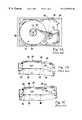
- FIG. 1Aillustrates a top plan view of a prior art disk drive 100 mounted to a frame 102 of a computer.
- FIGS. 1B and 1Cillustrate a bottom perspective view of the prior art disk drive 100 during bending caused by a shock transferred to the disk drive 100 .
- the bending illustrated in FIGS. 1B and 1 Cis exaggerated for clarity.
- the disk drive 100includes a drive housing 104 having a base 106 and four, spaced apart threaded apertures 108 .
- a bolt(not shown) is threaded into each of the threaded apertures 108 to secure the drive housing 100 to the frame 102 .
- the threaded apertures 108are asymmetrically located on the drive housing 104 . As illustrated in FIGS. 1B and 1C, this unbalanced mounting scheme causes the drive housing 104 to bend and flex along a housing flex line 110 when the frame 102 is subjected to a shock impulse. Stated another way, because all of the threaded apertures 108 are asymmetrically located, a portion of the drive housing 104 cantilevers and flexes on the housing flex line 110 somewhat similar to a diving board.
- a disk assembly 112is mounted on one side of the flex line 110 while an actuator assembly 114 , including actuator arms 116 are attached to the base 106 on the other side of the flex line 110 .
- flexing of the drive housing 104causes movement of the actuator assembly 114 relative to the disk assembly 112 .
- the movement to the actuator assembly 114is amplified by the long, cantilevering actuator arms 116 .
- Thiscan cause the transducer heads 118 attached to the distal ends of the actuator arms 116 to lift off of the storage disk 120 and subsequently slam or slap back into the storage disk 120 .
- Thisis commonly referred to as “head slap” in the industry. Head slap can lead to loss of data due to erosion or scarring of the magnetic film on the storage disk 120 , debris particles in the disk assembly 112 , as well as damage to the transducer heads 118 .
- One attempt to solve the problemincludes isolating the entire disk drive by using four, soft shock absorbing mounts to mount the drive housing to the frame.
- the soft mountsare effective in protecting the disk drive from shock.
- the soft mountsrequire more physical space than rigid mounts to implement.
- the performance level of the disk driveis reduced because of the compliant nature of the soft mounts. More specifically, the soft mounts give during movement by the actuator motor and decrease the performance of actuator motor.
- the present inventionis directed to a mounting assembly for securing a disk drive to a frame of a computer which satisfies these objectives.
- the disk driveincludes a drive housing having a first mounting location and a second mounting location.
- the mounting assemblyincluding a first rigid mount and a flexible mount. The first rigid mount rigidly secures the second mounting location to the frame. The flexible mount flexibly secures the first mounting location to the frame.
- the flexible mountdiminishes the level of vibration transferred from the frame to the drive housing at the flexible mount and facilitates flexing of the drive housing intermediate the first mounting location and the second mounting location. More specifically, the flexible mount facilitates flexing of the drive housing along a housing flex line which extends across the drive housing in between the first mounting location and the second mounting location. Flexing along the housing flex line will reduce the amplifying effects of the long actuator arms. Thus, flexing of the drive housing is less likely to cause a transducer head to lift off of a storage disk. This diminishes the effects of a shock to the drive housing, the level and frequency of head slap and the risk of data loss due to erosion or scarring of the storage disk.
- the flexible mountflexes in a direction substantially perpendicular to a base of the drive housing and inhibits flexing in a direction substantially parallel the base of the drive housing. This allows the drive housing to move up and down at the first mounting location and not transversely.
- the flexible mountis a deflecting clip which secures the first mounting location to the drive housing.
- the deflecting clipincludes a clip guide which interacts with a housing aperture in the drive housing to inhibit the deflecting clip from moving in a direction substantially parallel to a base of the drive housing.
- the present inventionalso includes a method for attaching a disk drive to a frame.
- the methodincludes the steps of providing a drive housing including four mounting locations and fixedly securing three of the mounting locations to the frame. Because one of the mounting locations is not rigidly secured to the frame, the drive housing has a housing flex line positioned between the mounting location which is not rigidly secured to the frame and the other mounting locations upon a sufficient shock to the frame.
- the unique design of the mounting assemblydiminishes the effects of a shock pulse to the disk drive.
- the three rigid mountsprevent degradation in performance of the disk drive.
- the one flexible mountdampens the amount of shock pulse transferred from the frame to the drive housing at the flexible mount. Further, the flexible mount alters the housing flex line of the drive housing to minimize the effects of the shock pulse.
- FIG. 1Ais a top plan view of a prior art disk drive mounted to a frame
- FIG. 1Bis a bottom, perspective view of the prior art disk drive of FIG. 1A illustrating the bending of the disk drive;
- FIG. 1Cis a bottom, perspective view of the prior art disk drive of FIG. 1A illustrating the bending of the disk drive;
- FIG. 2is a top plan view of a disk drive having features of the present invention mounted to a frame of a computer;
- FIG. 3is a bottom, exploded, perspective, assembly view of the disk drive and a portion of the frame of FIG. 2;
- FIG. 4is a bottom, perspective view illustrating flexing of the drive housing along the housing flex line
- FIG. 5is a top, perspective view of another embodiment of a drive housing.
- FIG. 6is a bottom, perspective view of the drive housing of FIG. 5 .
- a disk drive 10includes (i) a drive housing 12 , (ii) a disk assembly 14 including one or more storage disks 15 , (iii) an actuator assembly 16 for positioning a transducer head 18 proximate each storage disk 15 , and (iv) a mounting assembly 20 for securing the disk drive 10 to a frame 22 of a computer 24 .
- the mounting assembly 20dampens the level of vibration which is transferred to the disk drive 10 from a short duration shock pulse to frame 22 .
- the mounting assembly 20alters a housing flex line 26 of the drive housing 12 to minimize the effects of the vibration transferred to the drive housing 12 . This reduces the potential of damage to the storage disk 15 and/or the transducer head 18 .
- the frame 22 illustrated in the FIG. 3includes four spaced apart frame openings 28 for securing the drive housing 12 to the computer 24 .
- a length distance 29 between adjacent frame openings 28is approximately 44.45 millimeters and an across distance 31 between adjacent frame openings is approximately 95.25 millimeters pursuant to industry standards.
- the mounting assembly 20can be adapted to be used with an existing disk drive 10 .
- the pattern of the frame openings 28can be varied.
- the drive housing 12retains the various components of the disk drive 10 .
- the drive housing 12illustrated in Figures, is rectangular shaped and includes first and second, spaced apart, parallel end walls 30 , 32 , first and second spaced apart, parallel side walls 34 , 36 , a base 38 and a cover (not shown).
- the base 38 and coverare maintained apart by the walls 30 , 32 , 34 , 36 .
- the walls 30 , 32 , 34 , 36 and the base 38are typically formed as an integral unit for structural integrity.
- the drive housing 12 illustrated in FIGS. 3 and 4includes four spaced apart mounting locations 40 near the base 38 for interacting with the mounting assembly 20 and securing the bottom of the drive housing 12 to the frame 22 .
- These mounting locations 40are designated a first mounting location 40 a , a second mounting location 40 b , a third mounting location 40 c and a fourth mounting location 40 d for convenience of discussion.
- the first mounting location 40 ais positioned near the first side wall 34 intermediate the end walls 30 , 32 .
- the second mounting location 40 bis positioned near the second side wall 36 intermediate the end walls 30 , 32 .
- the third mounting location 40 cis positioned near the first side wall 34 and the first end wall 30 .
- the fourth mounting location 40 dis positioned near the second side wall 36 and the first end wall 30 .
- each mounting location 40includes an internally threaded aperture which is adapted to receive a portion of the mounting assembly 20 .
- the mounting locations 40 in this embodimentare asymmetrically positioned on the drive housing 12 .
- a transition line 44is illustrated in the FIGS. 3 and 4, to illustrate a division of the drive housing 12 into a first section 46 and a second section 48 which are substantially side-by-side.
- the transition line 44extends between the side walls 34 and 36 between the first and second mounting locations 40 a and 40 b and the second end wall 32 .
- the first section 46includes the four spaced apart mounting locations 40 for securing the drive housing 12 to the frame 22 .
- the second section 48has no mounting locations and cantilevers relative to the first section 46 .
- the disk assembly 14includes one or more spaced apart storage disks 15 which are secured to a spindle hub 50 .
- the spindle hub 50rotates relative to a spindle shaft (not shown) which is secured to the base 38 in the first section 46 .
- a spindle motor(not shown) rotates the spindle hub 50 and the storage disks 15 at a constant angular velocity.
- the rotation rate of the storage disks 12varies according to the design of the disk drive 10 .
- Each storage disk 15stores data in a form that can be subsequently retrieved if necessary.
- Magnetic storage disks 15are commonly used to store data in digital form.
- each storage diskpreferably includes a data storage surface on each side of the storage disk 15 .
- the storage disks 15are manufactured by ways known to those skilled in the art.
- the actuator assembly 16depends upon the design of the disk drive 10 .
- the actuator assembly 16includes an E block 52 and an actuator motor 54 .
- the E block 52is defined by an actuator hub 56 and one or more actuator arms 58 which cantilever away from the actuator hub 56 .
- Each actuator arm 58includes a longitudinal axis 59 .
- the actuator hub 56rotates on an actuator shaft (not shown) which is secured to the base 38 in the second section 48 .
- the actuator shaftis secured to the base 38 near the first and second mounting locations 40 a , 40 b . Further, the actuator shaft is secured to the base 38 closer to the second mounting location 40 b than the first mounting location 40 a.
- the actuator arms 58rotate with the actuator hub 56 and position the transducer heads 18 near the storage surfaces of the storage disks 15 .
- the number and spacing of the actuator arms 58varies according to the number and spacing of the disks 15 . For example, a disk drive 10 which includes five disks would require six actuator arms 58 .
- a load beam 60is used to attach each transducer head 18 to a distal end of one of the actuator arms 58 .
- Each load beam 60is flexible in a direction perpendicular to the storage disk 15 and acts as a spring for supporting a transducer head 18 . As the disks 15 rotate, air flow between the transducer head 18 and storage disk 15 causes the transducer head 18 to ride at an aerodynamically stabilized distance from the storage disk 15 .
- Each load beam 60is resilient and biased to urge each transducer head 18 towards the storage disk 15 .
- the single transducer head 18interacts with a single storage surface on one of the storage disks 15 to access or transfer information to the storage disk 15 .
- the transducer head 18is commonly referred to as a read/write head. It is anticipated that the present device can be utilized for data transducers other than read/write heads for a magnetic storage disk.
- the actuator motor 54precisely moves the actuator hub 56 , actuator arms 58 and the transducer heads 18 relative to the storage disks 15 to retrieve information from the storage disk 15 .
- the actuator motor 54is a rotary voice coil actuator.
- the actuator motor 54could be a linear induction motor which moves radially with respect to the disks 15 .
- the disk drive 10includes an actuator latch (not shown) which inhibits rotation of the actuator hub 56 and retains the transducer head 18 in a landing zone of the storage disk 15 during non-rotation of the storage disk 15 . This reduces the potential of damage to the storage disk 15 when the transducer head 18 is not flying on an air bearing generated by the rotation of the disk 15 .
- the mounting assembly 20secures the drive housing 12 to the frame 22 and facilitates flexing of the drive housing 12 between the first mounting location 40 a and the other mounting locations 40 b-c. Stated another way, the mounting assembly 20 facilitates flexing of the drive housing 12 along the housing flex line 26 which extends across the drive housing 12 from the first side wall 34 to the second side wall 36 in between the first mounting location 40 a and the second mounting location 40 b .
- the flexing 61 of the drive housing 12 illustrated in FIG. 4is exaggerated for clarity.
- the housing flex line 26is not parallel or on with the transition line 44 . Further, as illustrated in FIG. 2, the housing flex line 26 extends under the storage disks 15 , across the first section 46 , and approaches parallel with the longitudinal axis 59 of the actuator arms 58 . Thus, flexing of the drive housing 12 tends to result in movement of the actuator arms 58 around the longitudinal axis 59 . This minimizes the amplifying effect of the cantilevering actuator arms 58 and minimizes movement of the transducer head 18 relative to the storage disk 15 during flexing of the drive housing 12 .
- the mounting assembly 20includes a first substantially rigid mount 62 , a second substantially rigid mount 64 , a third substantially rigid mount 66 , and a substantially flexible mount 68 .
- Each mount 62 , 64 , 66 , 68secures one of the mounting locations 40 to the frame 22 .
- each rigid mount 62 , 64 , 66is a bolt which includes an externally threaded surface. The bolt extends through the frame openings 28 and threads into one of the mounting locations 40 .
- the rigid mounts 62 , 64 , 66solidly attach the drive housing 12 to the frame 22 to inhibit degradation in the performance of the actuator motor 54 .
- the flexible mount 68is adapted to flexibly secure the first mounting location 40 a to the frame 22 .
- the flexible mount 68diminishes the level of vibration transferred from the frame 22 at the flexible mount 68 to drive housing 12 and facilitates flexing of the drive housing 12 intermediate the first mounting location 40 a and the second mounting location 40 b . Because the flexible mount 68 is secured to the first mounting location 40 a , the housing flex line 26 is closer to parallel with the longitudinal axis 59 of the actuator arms 58 to minimize the amplifying effects of the actuator arms 58 during flexing.
- the flexible mount 68preferably flexes in a direction substantially perpendicular to the base 38 of the drive housing 12 and inhibits flexing in a direction substantially parallel the base 38 of the drive housing 12 .
- the flexible mount 68includes a deflecting clip 70 , a first clip bolt 72 and a second clip bolt 74 for attaching the first mounting location 40 a to the frame 22 .
- the deflecting clip 70can be varied to suit the design of the disk drive 10 .
- the deflecting clip 70includes a clip body 76 , a pair of spaced apart clip guides 78 and a clip lip 80 .
- the clip body 76fits into a housing notch 82 in the first side wall 34 .
- the clip guides 78extend away from the clip body 76 .
- One of the clip guides 78includes a clip tab 83 which extends away from the clip guide 78 and fits into a housing aperture 84 in the first side wall 34 to inhibit the deflecting clip 70 from moving in a direction substantially parallel to the base 38 of the drive housing 12 .
- the clip lip 80includes a lip aperture 86 which receives the first clip bolt 72 to attach the deflecting clip 70 to the first mounting location 40 a .
- the clip body 76also includes a clip mounting location 88 having an internally threaded aperture which receives the second clip bolt 74 to attach the deflecting clip 70 to the frame 22 .
- FIGS. 5 and 6illustrate another embodiment of a drive housing 12 in which the sides of the disk drive 10 are secured to the frame (not shown in FIGS. 5 and 6 ).
- the drive housing 12includes three mounting locations 40 on each of the side walls 34 , 36 of the drive housing 12 .
- the center mounting locations 40 on each side wall 34 , 36is not used for attaching the disk drive 10 to the frame.
- the remaining four mounting locations 40are designated 40 a - 40 d similar to embodiment illustrated in FIGS. 3 and 4.
- each mounting location 40includes an internally threaded aperture for receiving the flexible mount 68 or one of the rigid mounts 62 , 64 , 66 .
- each of the rigid mounts 62 , 64 , 66is a bolt which engages one of the mounting locations 40 .
- the flexible mount 68includes the deflecting clip 70 , the first clip bolt 72 , and the second clip bolt 74 for attaching the first mounting location 40 a to the frame.
- the deflecting clip 70includes the clip body 76 and a pair of spaced apart clip protruding lips 90 which interact with the first side wall 34 .
- the protruding lips 90maintain stability of the deflecting clip 70 in a direction substantially parallel to the base 38 while allowing for flexibility substantially perpendicular to the base 38 .
- One of the protruding lips 90includes the clip mounting location 88 having an internally threaded aperture which receives the second clip bolt 74 to attach the deflecting clip 70 to the frame.
- the clip body 76includes the lip aperture 86 which receives the first clip bolt 72 to attach the deflecting clip 70 to the first mounting location 40 a.
- the distance between the mounting locations 40can be varied.
- the distance between the second mounting location 40 b and the fourth mounting location 40 dis approximately 101.6 millimeters and the distance between the third mounting location 40 c and the fourth mounting location 40 d is approximately 101.6 millimeters pursuant to industry standards.
- the present inventionovercomes the problems associated with prior art mounting assemblies because the rigid mounts 62 , 64 , 66 prevent degradation of actuator motor performance while the flexible mount 68 diminishes the level of vibration transferred to the disk housing 12 at the flexible mount 68 . Further, the mounting assembly 16 alters the housing flex line 26 to minimize the effects of the cantilevering actuator arms 58 . This minimizes the level and amount of head slap to protect the storage disk 15 and the transducer head 18 .
Landscapes
- Moving Of Heads (AREA)
Abstract
Description
Claims (19)
Priority Applications (1)
| Application Number | Priority Date | Filing Date | Title |
|---|---|---|---|
| US09/203,775US6297928B1 (en) | 1998-12-02 | 1998-12-02 | Mounting assembly for a disk drive |
Applications Claiming Priority (1)
| Application Number | Priority Date | Filing Date | Title |
|---|---|---|---|
| US09/203,775US6297928B1 (en) | 1998-12-02 | 1998-12-02 | Mounting assembly for a disk drive |
Publications (1)
| Publication Number | Publication Date |
|---|---|
| US6297928B1true US6297928B1 (en) | 2001-10-02 |
Family
ID=22755249
Family Applications (1)
| Application Number | Title | Priority Date | Filing Date |
|---|---|---|---|
| US09/203,775Expired - Fee RelatedUS6297928B1 (en) | 1998-12-02 | 1998-12-02 | Mounting assembly for a disk drive |
Country Status (1)
| Country | Link |
|---|---|
| US (1) | US6297928B1 (en) |
Cited By (6)
| Publication number | Priority date | Publication date | Assignee | Title |
|---|---|---|---|---|
| USD512061S1 (en)* | 2004-04-20 | 2005-11-29 | Kabushiki Kaisha Toshiba | Hard disk drive |
| US20060002076A1 (en)* | 2004-06-30 | 2006-01-05 | Albrecht David W | Shock mount assembly for attachment of an electronic device to a support structure |
| USD514564S1 (en)* | 2004-04-20 | 2006-02-07 | Kabushiki Kaisha Toshiba | Hard disk drive |
| US20060098404A1 (en)* | 2004-11-05 | 2006-05-11 | Sri-Jayantha Sri M | Apparatus for a shock absorber that allows a disk drive to move with respect to the chassis of a computer system |
| US20060098399A1 (en)* | 2004-11-05 | 2006-05-11 | Sri-Jayantha Sri M | Method for manufacturing a shock absorber that allows a disk drive to move with respect to the chassis of a computer system |
| US8031431B1 (en)* | 2009-03-02 | 2011-10-04 | Western Digital Technologies, Inc. | Disk drive having a top cover with anchor tabs |
Citations (6)
| Publication number | Priority date | Publication date | Assignee | Title |
|---|---|---|---|---|
| US4713714A (en)* | 1985-11-26 | 1987-12-15 | Motorola Computer Systems, Inc. | Computer peripheral shock mount for limiting motion-induced errors |
| US5654875A (en)* | 1996-07-26 | 1997-08-05 | Ibm | Isolator mounting system for small form factor hard disk drive |
| US5677811A (en)* | 1995-01-31 | 1997-10-14 | Kabushiki Kaisha Toshiba | Magnetic disk device including computer chassis mounting provisions for suppressing internally and externally generated noise currents |
| US6075695A (en)* | 1997-02-21 | 2000-06-13 | Mitsumi Electric Co., Ltd. | Mounting structure of magnetic disk drive into main body of computer |
| US6097608A (en)* | 1998-11-16 | 2000-08-01 | International Business Machines Corporation | Disk drive vibration isolation using diaphragm isolators |
| US6122165A (en)* | 1998-11-10 | 2000-09-19 | Dell Computer Corporation | Computer with improved hard drive assembly and method for assembling same |
- 1998
- 1998-12-02USUS09/203,775patent/US6297928B1/ennot_activeExpired - Fee Related
Patent Citations (6)
| Publication number | Priority date | Publication date | Assignee | Title |
|---|---|---|---|---|
| US4713714A (en)* | 1985-11-26 | 1987-12-15 | Motorola Computer Systems, Inc. | Computer peripheral shock mount for limiting motion-induced errors |
| US5677811A (en)* | 1995-01-31 | 1997-10-14 | Kabushiki Kaisha Toshiba | Magnetic disk device including computer chassis mounting provisions for suppressing internally and externally generated noise currents |
| US5654875A (en)* | 1996-07-26 | 1997-08-05 | Ibm | Isolator mounting system for small form factor hard disk drive |
| US6075695A (en)* | 1997-02-21 | 2000-06-13 | Mitsumi Electric Co., Ltd. | Mounting structure of magnetic disk drive into main body of computer |
| US6122165A (en)* | 1998-11-10 | 2000-09-19 | Dell Computer Corporation | Computer with improved hard drive assembly and method for assembling same |
| US6097608A (en)* | 1998-11-16 | 2000-08-01 | International Business Machines Corporation | Disk drive vibration isolation using diaphragm isolators |
Cited By (9)
| Publication number | Priority date | Publication date | Assignee | Title |
|---|---|---|---|---|
| USD512061S1 (en)* | 2004-04-20 | 2005-11-29 | Kabushiki Kaisha Toshiba | Hard disk drive |
| USD514564S1 (en)* | 2004-04-20 | 2006-02-07 | Kabushiki Kaisha Toshiba | Hard disk drive |
| US20060002076A1 (en)* | 2004-06-30 | 2006-01-05 | Albrecht David W | Shock mount assembly for attachment of an electronic device to a support structure |
| US7106582B2 (en)* | 2004-06-30 | 2006-09-12 | Hitachi Global Storage Technologies Netherlands B.V. | Shock mount assembly for attachment of an electronic device to a support structure |
| US20060098404A1 (en)* | 2004-11-05 | 2006-05-11 | Sri-Jayantha Sri M | Apparatus for a shock absorber that allows a disk drive to move with respect to the chassis of a computer system |
| US20060098399A1 (en)* | 2004-11-05 | 2006-05-11 | Sri-Jayantha Sri M | Method for manufacturing a shock absorber that allows a disk drive to move with respect to the chassis of a computer system |
| US7248467B2 (en) | 2004-11-05 | 2007-07-24 | Hitachi Global Storage Technologies Netherlands B.V. | Apparatus for a shock absorber that allows a disk drive to move with respect to the chassis of a computer system |
| US7559132B2 (en) | 2004-11-05 | 2009-07-14 | Hitachi Global Storage Technologies Netherlands B.V. | Method for manufacturing a shock absorber that allows a disk drive to move with respect to the chassis of a computer system |
| US8031431B1 (en)* | 2009-03-02 | 2011-10-04 | Western Digital Technologies, Inc. | Disk drive having a top cover with anchor tabs |
Similar Documents
| Publication | Publication Date | Title |
|---|---|---|
| US6549376B1 (en) | Gimbal suspension with vibration damper | |
| US5455728A (en) | Disk drive employing compact magnetic actuator latch mechanism | |
| US6452753B1 (en) | Universal load/unload ramp | |
| US6473270B1 (en) | Actuator shock snubber | |
| KR100653291B1 (en) | Apparatus and method for writing servo patterns on a computer hard disk | |
| KR100753074B1 (en) | Head suspension and disk drive unit | |
| US6704161B1 (en) | Shock protection skin bumper for a hard disk drive | |
| US4992898A (en) | Magnetic head slider suspension assembly having inverted load rails | |
| US5936808A (en) | Disk drive rotary actuator having arm with cross-member containing elastomeric damping member | |
| US20080226949A1 (en) | Damper for use in data storage applications | |
| US20050152070A1 (en) | Magnetic head actuator and magnetic disk device | |
| US6538853B1 (en) | E-block having improved resonance characteristics and improved fragility | |
| US7532440B2 (en) | Dual stage, head stack assembly for a disk drive | |
| US6229677B1 (en) | Disc drive actuator arm assembly with outer arm z-height less than inner arm z-height | |
| US6064547A (en) | Damped disk separator | |
| US6417986B1 (en) | Impact guard for limiting hard disk movement | |
| US6297928B1 (en) | Mounting assembly for a disk drive | |
| US4935830A (en) | Electro-magnetic shield structure for shielding a servo magnetic head of a magnetic disk storage device | |
| US6477000B1 (en) | Actuator arm disc snubber with unitary construction | |
| US6674608B1 (en) | Damped protective cover to improve disc drive acoustics | |
| US7016157B1 (en) | E-block having improved resonance characteristics and improved fragility | |
| USH1425H (en) | Head suspension assembly having improved frequency response, accurate head positioning and minimized flying variation | |
| US6570742B2 (en) | Head actuator with head support excitation shield | |
| US6920019B2 (en) | Device and method for improved stiction reliability in disk drives employing padded sliders | |
| KR100362582B1 (en) | Method and device for limiting head movement within a hard disk drive |
Legal Events
| Date | Code | Title | Description |
|---|---|---|---|
| AS | Assignment | Owner name:QUANTUM CORPORATION, CALIFORNIA Free format text:ASSIGNMENT OF ASSIGNORS INTEREST;ASSIGNORS:HAHN, PETER;LIN, ARTHUR;CHOI, SHIN JOHN;AND OTHERS;REEL/FRAME:009815/0749 Effective date:19990126 | |
| AS | Assignment | Owner name:MAXTOR CORPORATION, CALIFORNIA Free format text:ASSIGNMENT OF ASSIGNORS INTEREST;ASSIGNOR:QUANTUM CORPORATION;REEL/FRAME:012653/0726 Effective date:20010724 | |
| FPAY | Fee payment | Year of fee payment:4 | |
| FPAY | Fee payment | Year of fee payment:8 | |
| AS | Assignment | Owner name:WELLS FARGO BANK, NATIONAL ASSOCIATION, AS COLLATERAL AGENT AND SECOND PRIORITY REPRESENTATIVE, CALIFORNIA Free format text:SECURITY AGREEMENT;ASSIGNORS:MAXTOR CORPORATION;SEAGATE TECHNOLOGY LLC;SEAGATE TECHNOLOGY INTERNATIONAL;REEL/FRAME:022757/0017 Effective date:20090507 Owner name:JPMORGAN CHASE BANK, N.A., AS ADMINISTRATIVE AGENT AND FIRST PRIORITY REPRESENTATIVE, NEW YORK Free format text:SECURITY AGREEMENT;ASSIGNORS:MAXTOR CORPORATION;SEAGATE TECHNOLOGY LLC;SEAGATE TECHNOLOGY INTERNATIONAL;REEL/FRAME:022757/0017 Effective date:20090507 Owner name:JPMORGAN CHASE BANK, N.A., AS ADMINISTRATIVE AGENT Free format text:SECURITY AGREEMENT;ASSIGNORS:MAXTOR CORPORATION;SEAGATE TECHNOLOGY LLC;SEAGATE TECHNOLOGY INTERNATIONAL;REEL/FRAME:022757/0017 Effective date:20090507 Owner name:WELLS FARGO BANK, NATIONAL ASSOCIATION, AS COLLATE Free format text:SECURITY AGREEMENT;ASSIGNORS:MAXTOR CORPORATION;SEAGATE TECHNOLOGY LLC;SEAGATE TECHNOLOGY INTERNATIONAL;REEL/FRAME:022757/0017 Effective date:20090507 | |
| AS | Assignment | Owner name:SEAGATE TECHNOLOGY INTERNATIONAL, CALIFORNIA Free format text:RELEASE;ASSIGNOR:JPMORGAN CHASE BANK, N.A., AS ADMINISTRATIVE AGENT;REEL/FRAME:025662/0001 Effective date:20110114 Owner name:MAXTOR CORPORATION, CALIFORNIA Free format text:RELEASE;ASSIGNOR:JPMORGAN CHASE BANK, N.A., AS ADMINISTRATIVE AGENT;REEL/FRAME:025662/0001 Effective date:20110114 Owner name:SEAGATE TECHNOLOGY LLC, CALIFORNIA Free format text:RELEASE;ASSIGNOR:JPMORGAN CHASE BANK, N.A., AS ADMINISTRATIVE AGENT;REEL/FRAME:025662/0001 Effective date:20110114 Owner name:SEAGATE TECHNOLOGY HDD HOLDINGS, CALIFORNIA Free format text:RELEASE;ASSIGNOR:JPMORGAN CHASE BANK, N.A., AS ADMINISTRATIVE AGENT;REEL/FRAME:025662/0001 Effective date:20110114 | |
| AS | Assignment | Owner name:THE BANK OF NOVA SCOTIA, AS ADMINISTRATIVE AGENT, CANADA Free format text:SECURITY AGREEMENT;ASSIGNOR:SEAGATE TECHNOLOGY LLC;REEL/FRAME:026010/0350 Effective date:20110118 Owner name:THE BANK OF NOVA SCOTIA, AS ADMINISTRATIVE AGENT, Free format text:SECURITY AGREEMENT;ASSIGNOR:SEAGATE TECHNOLOGY LLC;REEL/FRAME:026010/0350 Effective date:20110118 | |
| REMI | Maintenance fee reminder mailed | ||
| AS | Assignment | Owner name:SEAGATE TECHNOLOGY US HOLDINGS, INC., CALIFORNIA Free format text:TERMINATION AND RELEASE OF SECURITY INTEREST IN PATENT RIGHTS;ASSIGNOR:WELLS FARGO BANK, NATIONAL ASSOCIATION, AS COLLATERAL AGENT AND SECOND PRIORITY REPRESENTATIVE;REEL/FRAME:030833/0001 Effective date:20130312 Owner name:SEAGATE TECHNOLOGY INTERNATIONAL, CAYMAN ISLANDS Free format text:TERMINATION AND RELEASE OF SECURITY INTEREST IN PATENT RIGHTS;ASSIGNOR:WELLS FARGO BANK, NATIONAL ASSOCIATION, AS COLLATERAL AGENT AND SECOND PRIORITY REPRESENTATIVE;REEL/FRAME:030833/0001 Effective date:20130312 Owner name:EVAULT INC. (F/K/A I365 INC.), CALIFORNIA Free format text:TERMINATION AND RELEASE OF SECURITY INTEREST IN PATENT RIGHTS;ASSIGNOR:WELLS FARGO BANK, NATIONAL ASSOCIATION, AS COLLATERAL AGENT AND SECOND PRIORITY REPRESENTATIVE;REEL/FRAME:030833/0001 Effective date:20130312 Owner name:SEAGATE TECHNOLOGY LLC, CALIFORNIA Free format text:TERMINATION AND RELEASE OF SECURITY INTEREST IN PATENT RIGHTS;ASSIGNOR:WELLS FARGO BANK, NATIONAL ASSOCIATION, AS COLLATERAL AGENT AND SECOND PRIORITY REPRESENTATIVE;REEL/FRAME:030833/0001 Effective date:20130312 | |
| LAPS | Lapse for failure to pay maintenance fees | ||
| STCH | Information on status: patent discontinuation | Free format text:PATENT EXPIRED DUE TO NONPAYMENT OF MAINTENANCE FEES UNDER 37 CFR 1.362 | |
| FP | Lapsed due to failure to pay maintenance fee | Effective date:20131002 | |
| AS | Assignment | Owner name:SEAGATE TECHNOLOGY PUBLIC LIMITED COMPANY, CALIFORNIA Free format text:RELEASE BY SECURED PARTY;ASSIGNOR:THE BANK OF NOVA SCOTIA;REEL/FRAME:072193/0001 Effective date:20250303 Owner name:SEAGATE TECHNOLOGY, CALIFORNIA Free format text:RELEASE BY SECURED PARTY;ASSIGNOR:THE BANK OF NOVA SCOTIA;REEL/FRAME:072193/0001 Effective date:20250303 Owner name:SEAGATE TECHNOLOGY HDD HOLDINGS, CALIFORNIA Free format text:RELEASE BY SECURED PARTY;ASSIGNOR:THE BANK OF NOVA SCOTIA;REEL/FRAME:072193/0001 Effective date:20250303 Owner name:I365 INC., CALIFORNIA Free format text:RELEASE BY SECURED PARTY;ASSIGNOR:THE BANK OF NOVA SCOTIA;REEL/FRAME:072193/0001 Effective date:20250303 Owner name:SEAGATE TECHNOLOGY LLC, CALIFORNIA Free format text:RELEASE BY SECURED PARTY;ASSIGNOR:THE BANK OF NOVA SCOTIA;REEL/FRAME:072193/0001 Effective date:20250303 Owner name:SEAGATE TECHNOLOGY INTERNATIONAL, CAYMAN ISLANDS Free format text:RELEASE BY SECURED PARTY;ASSIGNOR:THE BANK OF NOVA SCOTIA;REEL/FRAME:072193/0001 Effective date:20250303 Owner name:SEAGATE HDD CAYMAN, CAYMAN ISLANDS Free format text:RELEASE BY SECURED PARTY;ASSIGNOR:THE BANK OF NOVA SCOTIA;REEL/FRAME:072193/0001 Effective date:20250303 Owner name:SEAGATE TECHNOLOGY (US) HOLDINGS, INC., CALIFORNIA Free format text:RELEASE BY SECURED PARTY;ASSIGNOR:THE BANK OF NOVA SCOTIA;REEL/FRAME:072193/0001 Effective date:20250303 |