US6296968B1 - One-piece battery incorporating a circulating fluid type heat exchanger - Google Patents
One-piece battery incorporating a circulating fluid type heat exchangerDownload PDFInfo
- Publication number
- US6296968B1 US6296968B1US09/327,534US32753499AUS6296968B1US 6296968 B1US6296968 B1US 6296968B1US 32753499 AUS32753499 AUS 32753499AUS 6296968 B1US6296968 B1US 6296968B1
- Authority
- US
- United States
- Prior art keywords
- tank
- flanges
- manifold
- battery
- units
- Prior art date
- Legal status (The legal status is an assumption and is not a legal conclusion. Google has not performed a legal analysis and makes no representation as to the accuracy of the status listed.)
- Expired - Lifetime
Links
Images


Classifications
- F—MECHANICAL ENGINEERING; LIGHTING; HEATING; WEAPONS; BLASTING
- F28—HEAT EXCHANGE IN GENERAL
- F28F—DETAILS OF HEAT-EXCHANGE AND HEAT-TRANSFER APPARATUS, OF GENERAL APPLICATION
- F28F3/00—Plate-like or laminated elements; Assemblies of plate-like or laminated elements
- F28F3/12—Elements constructed in the shape of a hollow panel, e.g. with channels
- B—PERFORMING OPERATIONS; TRANSPORTING
- B60—VEHICLES IN GENERAL
- B60L—PROPULSION OF ELECTRICALLY-PROPELLED VEHICLES; SUPPLYING ELECTRIC POWER FOR AUXILIARY EQUIPMENT OF ELECTRICALLY-PROPELLED VEHICLES; ELECTRODYNAMIC BRAKE SYSTEMS FOR VEHICLES IN GENERAL; MAGNETIC SUSPENSION OR LEVITATION FOR VEHICLES; MONITORING OPERATING VARIABLES OF ELECTRICALLY-PROPELLED VEHICLES; ELECTRIC SAFETY DEVICES FOR ELECTRICALLY-PROPELLED VEHICLES
- B60L50/00—Electric propulsion with power supplied within the vehicle
- B60L50/50—Electric propulsion with power supplied within the vehicle using propulsion power supplied by batteries or fuel cells
- B60L50/60—Electric propulsion with power supplied within the vehicle using propulsion power supplied by batteries or fuel cells using power supplied by batteries
- B60L50/64—Constructional details of batteries specially adapted for electric vehicles
- B—PERFORMING OPERATIONS; TRANSPORTING
- B60—VEHICLES IN GENERAL
- B60L—PROPULSION OF ELECTRICALLY-PROPELLED VEHICLES; SUPPLYING ELECTRIC POWER FOR AUXILIARY EQUIPMENT OF ELECTRICALLY-PROPELLED VEHICLES; ELECTRODYNAMIC BRAKE SYSTEMS FOR VEHICLES IN GENERAL; MAGNETIC SUSPENSION OR LEVITATION FOR VEHICLES; MONITORING OPERATING VARIABLES OF ELECTRICALLY-PROPELLED VEHICLES; ELECTRIC SAFETY DEVICES FOR ELECTRICALLY-PROPELLED VEHICLES
- B60L58/00—Methods or circuit arrangements for monitoring or controlling batteries or fuel cells, specially adapted for electric vehicles
- B60L58/10—Methods or circuit arrangements for monitoring or controlling batteries or fuel cells, specially adapted for electric vehicles for monitoring or controlling batteries
- B60L58/24—Methods or circuit arrangements for monitoring or controlling batteries or fuel cells, specially adapted for electric vehicles for monitoring or controlling batteries for controlling the temperature of batteries
- B60L58/26—Methods or circuit arrangements for monitoring or controlling batteries or fuel cells, specially adapted for electric vehicles for monitoring or controlling batteries for controlling the temperature of batteries by cooling
- H—ELECTRICITY
- H01—ELECTRIC ELEMENTS
- H01M—PROCESSES OR MEANS, e.g. BATTERIES, FOR THE DIRECT CONVERSION OF CHEMICAL ENERGY INTO ELECTRICAL ENERGY
- H01M10/00—Secondary cells; Manufacture thereof
- H01M10/60—Heating or cooling; Temperature control
- H01M10/61—Types of temperature control
- H01M10/613—Cooling or keeping cold
- H—ELECTRICITY
- H01—ELECTRIC ELEMENTS
- H01M—PROCESSES OR MEANS, e.g. BATTERIES, FOR THE DIRECT CONVERSION OF CHEMICAL ENERGY INTO ELECTRICAL ENERGY
- H01M10/00—Secondary cells; Manufacture thereof
- H01M10/60—Heating or cooling; Temperature control
- H01M10/62—Heating or cooling; Temperature control specially adapted for specific applications
- H01M10/625—Vehicles
- H—ELECTRICITY
- H01—ELECTRIC ELEMENTS
- H01M—PROCESSES OR MEANS, e.g. BATTERIES, FOR THE DIRECT CONVERSION OF CHEMICAL ENERGY INTO ELECTRICAL ENERGY
- H01M10/00—Secondary cells; Manufacture thereof
- H01M10/60—Heating or cooling; Temperature control
- H01M10/65—Means for temperature control structurally associated with the cells
- H01M10/655—Solid structures for heat exchange or heat conduction
- H01M10/6556—Solid parts with flow channel passages or pipes for heat exchange
- H01M10/6557—Solid parts with flow channel passages or pipes for heat exchange arranged between the cells
- H—ELECTRICITY
- H01—ELECTRIC ELEMENTS
- H01M—PROCESSES OR MEANS, e.g. BATTERIES, FOR THE DIRECT CONVERSION OF CHEMICAL ENERGY INTO ELECTRICAL ENERGY
- H01M10/00—Secondary cells; Manufacture thereof
- H01M10/60—Heating or cooling; Temperature control
- H01M10/65—Means for temperature control structurally associated with the cells
- H01M10/656—Means for temperature control structurally associated with the cells characterised by the type of heat-exchange fluid
- H01M10/6567—Liquids
- H—ELECTRICITY
- H01—ELECTRIC ELEMENTS
- H01M—PROCESSES OR MEANS, e.g. BATTERIES, FOR THE DIRECT CONVERSION OF CHEMICAL ENERGY INTO ELECTRICAL ENERGY
- H01M50/00—Constructional details or processes of manufacture of the non-active parts of electrochemical cells other than fuel cells, e.g. hybrid cells
- H01M50/10—Primary casings; Jackets or wrappings
- H01M50/102—Primary casings; Jackets or wrappings characterised by their shape or physical structure
- H01M50/112—Monobloc comprising multiple compartments
- H—ELECTRICITY
- H01—ELECTRIC ELEMENTS
- H01M—PROCESSES OR MEANS, e.g. BATTERIES, FOR THE DIRECT CONVERSION OF CHEMICAL ENERGY INTO ELECTRICAL ENERGY
- H01M50/00—Constructional details or processes of manufacture of the non-active parts of electrochemical cells other than fuel cells, e.g. hybrid cells
- H01M50/20—Mountings; Secondary casings or frames; Racks, modules or packs; Suspension devices; Shock absorbers; Transport or carrying devices; Holders
- H01M50/258—Modular batteries; Casings provided with means for assembling
- H01M50/26—Assemblies sealed to each other in a non-detachable manner
- Y—GENERAL TAGGING OF NEW TECHNOLOGICAL DEVELOPMENTS; GENERAL TAGGING OF CROSS-SECTIONAL TECHNOLOGIES SPANNING OVER SEVERAL SECTIONS OF THE IPC; TECHNICAL SUBJECTS COVERED BY FORMER USPC CROSS-REFERENCE ART COLLECTIONS [XRACs] AND DIGESTS
- Y02—TECHNOLOGIES OR APPLICATIONS FOR MITIGATION OR ADAPTATION AGAINST CLIMATE CHANGE
- Y02E—REDUCTION OF GREENHOUSE GAS [GHG] EMISSIONS, RELATED TO ENERGY GENERATION, TRANSMISSION OR DISTRIBUTION
- Y02E60/00—Enabling technologies; Technologies with a potential or indirect contribution to GHG emissions mitigation
- Y02E60/10—Energy storage using batteries
- Y—GENERAL TAGGING OF NEW TECHNOLOGICAL DEVELOPMENTS; GENERAL TAGGING OF CROSS-SECTIONAL TECHNOLOGIES SPANNING OVER SEVERAL SECTIONS OF THE IPC; TECHNICAL SUBJECTS COVERED BY FORMER USPC CROSS-REFERENCE ART COLLECTIONS [XRACs] AND DIGESTS
- Y02—TECHNOLOGIES OR APPLICATIONS FOR MITIGATION OR ADAPTATION AGAINST CLIMATE CHANGE
- Y02P—CLIMATE CHANGE MITIGATION TECHNOLOGIES IN THE PRODUCTION OR PROCESSING OF GOODS
- Y02P70/00—Climate change mitigation technologies in the production process for final industrial or consumer products
- Y02P70/50—Manufacturing or production processes characterised by the final manufactured product
- Y—GENERAL TAGGING OF NEW TECHNOLOGICAL DEVELOPMENTS; GENERAL TAGGING OF CROSS-SECTIONAL TECHNOLOGIES SPANNING OVER SEVERAL SECTIONS OF THE IPC; TECHNICAL SUBJECTS COVERED BY FORMER USPC CROSS-REFERENCE ART COLLECTIONS [XRACs] AND DIGESTS
- Y02—TECHNOLOGIES OR APPLICATIONS FOR MITIGATION OR ADAPTATION AGAINST CLIMATE CHANGE
- Y02T—CLIMATE CHANGE MITIGATION TECHNOLOGIES RELATED TO TRANSPORTATION
- Y02T10/00—Road transport of goods or passengers
- Y02T10/60—Other road transportation technologies with climate change mitigation effect
- Y02T10/70—Energy storage systems for electromobility, e.g. batteries
- Y—GENERAL TAGGING OF NEW TECHNOLOGICAL DEVELOPMENTS; GENERAL TAGGING OF CROSS-SECTIONAL TECHNOLOGIES SPANNING OVER SEVERAL SECTIONS OF THE IPC; TECHNICAL SUBJECTS COVERED BY FORMER USPC CROSS-REFERENCE ART COLLECTIONS [XRACs] AND DIGESTS
- Y02—TECHNOLOGIES OR APPLICATIONS FOR MITIGATION OR ADAPTATION AGAINST CLIMATE CHANGE
- Y02T—CLIMATE CHANGE MITIGATION TECHNOLOGIES RELATED TO TRANSPORTATION
- Y02T90/00—Enabling technologies or technologies with a potential or indirect contribution to GHG emissions mitigation
- Y02T90/10—Technologies relating to charging of electric vehicles
- Y02T90/16—Information or communication technologies improving the operation of electric vehicles
- Y—GENERAL TAGGING OF NEW TECHNOLOGICAL DEVELOPMENTS; GENERAL TAGGING OF CROSS-SECTIONAL TECHNOLOGIES SPANNING OVER SEVERAL SECTIONS OF THE IPC; TECHNICAL SUBJECTS COVERED BY FORMER USPC CROSS-REFERENCE ART COLLECTIONS [XRACs] AND DIGESTS
- Y10—TECHNICAL SUBJECTS COVERED BY FORMER USPC
- Y10T—TECHNICAL SUBJECTS COVERED BY FORMER US CLASSIFICATION
- Y10T29/00—Metal working
- Y10T29/49—Method of mechanical manufacture
- Y10T29/49002—Electrical device making
- Y10T29/49108—Electric battery cell making
- Y10T29/4911—Electric battery cell making including sealing
Definitions
- the present inventionconcerns a one-piece battery incorporating a circulating fluid type heat exchanger.
- the electrode assemblies of a one-piece batteryare contained in cells of a single container.
- the containeris usually prism-shaped.
- Each electrode assemblycomprises alternating positive and negative electrodes separated from each other by a separator and impregnated with an electrolyte.
- the electrode assemblyhas two relatively smaller faces corresponding to the edges of the stacked electrodes and two relatively larger faces parallel to the surfaces of the electrodes.
- a one-piece nickel-cadmium or nickel-metal hydride batteryhas a capacity in the range from 5 Ah to 250 Ah.
- a one-piece battery including a compact cooling systemhas recently been proposed.
- the batteryhas a single prism-shaped plastics material container consisting of a tank and a lid carrying the terminals.
- the tankincludes cells in which the electrode assemblies are placed separated by partitions.
- the cooling systemincludes two flanges welded and sealed to respective opposite walls of the plastics material tank. Each flange defines with the corresponding wall a circulation compartment for the liquid having at the top an inlet orifice and an outlet orifice leading into the lid of the battery.
- a system of the above kindis preferably placed on the walls of the tank facing the edges of the electrodes.
- cooling the edges of the electrodesis insufficient to maintain the battery at a suitable temperature.
- To increase the heat exchange areait is therefore necessary for the heat to be transferred via the wall facing the relatively larger faces of each assembly.
- U.S. Pat. No. 5,356,735describes a one-piece battery including a heat exchanger of the above kind and whose container comprises a single prism-shaped tank and a lid in several parts.
- the liquid circulation compartmentsare formed by two facing flanges.
- the compartmentsconstitute partitions separating the cells. To this end the perimeter of the partitions is engaged in grooves formed on the walls of the tank.
- Each compartmentis individually connected to an inlet/outlet manifold.
- a coupling unitnested in a housing provides communication between each compartment and the manifold.
- each compartmentis connected to a common inlet and outlet by longitudinal manifolds formed in an attached lid.
- the two longitudinal manifoldsclutter the lid.
- the lidcarries only two terminals for connecting the battery to an external circuit. This requires the use of an internal electrical connection arrangement that has to pass in a sealed manner through the partition separating two contiguous cells and comprising the liquid circulation compartment. Lead-through devices are not sufficiently reliable electrically or mechanically to be used in an electric vehicle.
- Manifolds of increasing diameterare formed by joining two complementary parts of the lid, each carrying passages.
- the lidformed of three superposed parts, fits onto the tank.
- the dimensions of the various parts constituting the containerare fixed. Accordingly, each battery of given capacity has its own specific components, which makes industrial manufacture less flexible and more costly.
- the aim of the present inventionis to propose a one-piece battery provided with a compact and effective heat exchanger and which is simpler to manufacture and more reliable than prior art systems.
- Another aim of the present inventionis to propose a one-piece battery provided with a heat exchanger and in which the number of electrode assemblies can easily be modified.
- the present inventionconsists in a one-piece battery comprising a tank divided into cells each receiving an electrode assembly, closure means for the tank and a circulating fluid type heat exchanger facing relatively larger faces of the assembly, wherein the fluid flows in a compartment defined by two flanges, the compartment has a fluid inlet orifice communicating with a common inlet manifold and a fluid outlet orifice communicating with a common outlet manifold, the tank comprises at least two units, each unit comprises at least one of the cells delimited by at least one wall facing a relatively larger face of the assembly that constitutes one of the flanges, each unit further comprises a portion of the inlet manifold and the outlet manifold, and the units are fastened together so that the flanges when placed face-to-face form a sealed circulation compartment and the portions of the same manifold are aligned with each other.
- the one-piece battery of the inventioncomprises a tank that is generally, although not exclusively, made of plastics material.
- the tankis divided into cells by walls, each cell receiving an electrode assembly.
- the tankis formed by assembling a plurality of units side by side and fixing them together, for example welding them or gluing them together.
- Each unitprovides at least one cell delimited by walls, but can comprise two or more cells.
- Each unitis manufactured in one piece, for example molded in one piece. The units are therefore of unitary construction, which limits the number of joints.
- the batteryalso includes a circulating fluid type heat exchanger facing the relatively larger faces of the assembly.
- the fluidflows in a flat compartment defined by two flanges and which forms at least one of the walls between cells.
- the compartmenthas at the top a fluid inlet orifice communicating with a common inlet manifold and a fluid outlet orifice communicating with a common outlet manifold.
- each unit facing the relatively larger sides of the electrode assemblyconstitutes one of the flanges.
- the two opposite faces that face the relatively larger faces of the electrode assemblypreferably each constitute one flange. If the unit includes more than one cell, they are preferably attached together by the face opposite the edges of the electrodes.
- the unitsare interconnected so that the flange of one unit faces the flange of the contiguous unit to form a fluid circulation compartment.
- the units constituting the ends of the tankhave a contiguous unit on only one side. Only one of the walls facing the relatively larger faces of the electrode assembly constitutes one of the flanges, which is welded to the flange of the contiguous unit.
- the unit at the end of the batteryis advantageously connected on one side to the contiguous unit and on the side opposite the other elements to a plate constituting a flange for closing the circulation compartment.
- the compartment closed by the flangeconstitutes the outside lateral wall of the battery.
- the electrode assembly contained in the end unit of the batteryis therefore cooled via two opposite faces, in an analogous manner to the units at the center of the battery.
- closure meansare in the lower part of the tank and constitute a bottom fixed and sealed to the tank.
- the inlet manifold and the outlet manifoldare preferably on the face of the tank opposite the bottom.
- each unithas, on the face opposite the bottom, orifices to accommodate (for example) two terminals, a relief valve, an electrolyte filler orifice, etc. for each cell.
- the portions of the manifolds and likewise the orificesare formed at the same time as the unit, for example molded at the same time as the unit.
- Each cellhas a terminal for each polarity.
- the electrode assembliesare electrically connected outside the cells, eliminating the need for any internal electrical connection system.
- At least one of the flangespreferably carries a plurality of ribs forming chicanes for causing the fluid flowing in the compartment to flow alternately in one direction and in the opposite direction.
- one of the two flangeshas the fluid inlet and outlet orifices in its upper part, but each of the flanges forming the circulation compartment could carry half these orifices.
- Each unitfurther includes a portion of the inlet manifold and the outlet manifold.
- the fluid inlet and outlet orifices of each compartmentrespectively communicate with the corresponding manifold portion integral with the unit.
- the advantage of the present inventionis that it proposes a one-piece battery of modular design whose capacity can easily be modified by varying the number of cells, which are identical with the possible exception of the end cells, which incorporate minor modifications. Only the bottom differs in size, but it is also feasible for the bottom to be made from units previously welded together.
- the present inventionalso consists in a method of manufacturing a battery in accordance with the present invention.
- the methodcomprises the following steps:
- At least two of the unitsare molded in one piece
- the unitsare placed side by side so that the flanges are pressed together and the manifold portions match up,
- the bottomis welded to the tank.
- a plate constituting a flangeis welded to each end to obtain the tank.
- the present inventionhas the advantage of proposing a method of manufacturing a one-piece battery in which the units forming the tank are first heat-welded together, which seals the fluid circuit.
- the fluid circuithas no welds shared with the cells, which eliminates any risk of the fluid leaking into the cells.
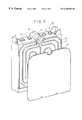
- FIG. 1is a perspective view of the container of a one-piece battery in accordance with the invention comprising ten electrode assemblies.
- FIG. 2is a view in section taken along the line II—II in FIG. 1 showing the arrangement of the electrode assemblies in the cells and the position of the fluid circulation compartment.
- FIG. 3shows the area III from FIG. 2 to a larger scale.
- FIG. 4shows a central unit of the tank from FIG. 1 which comprises two cells.
- FIG. 5which is analogous to FIG. 3, shows an end unit of the tank from FIG. 1 which comprises two cells.
- FIG. 1shows the prism-shaped container 1 of a battery in accordance with the invention.
- the container 1comprises a polypropylene tank 2 and closure means 3 constituting a bottom.
- the tank 2has two lateral walls 4 , two longitudinal walls 5 and a transverse top wall opposite the bottom 3 .
- the bottom 3is heat-welded to the tank 2 after the electrode assemblies have been inserted into their respective cells.
- the traverse wall of the tank 2incorporates two orifices 7 for each cell, respectively receiving a terminal of each polarity, and an opening 8 which is initially used to introduce the electrolyte and is closed by a relief valve after filling the cell.
- a central double inlet/outlet manifold 9joins up the inlets and outlets for the liquid flowing in the heat exchanger.
- the manifold 9has at each end an inlet pipe 10 and an outlet pipe 11 for connection to a liquid circulation system or to another one-piece battery.
- FIG. 2shows the battery in accordance with the invention in horizontal section and FIG. 3 shows part of this figure to a larger scale.
- the tank 2is divided into cells 20 each adapted to contain an electrode assembly 21 comprising an alternating assembly 22 of positive and negative electrodes separated from each other by a separator 23 .
- the cells 20are joined side-by-side via their faces 24 that face the edge of the electrodes.
- the walls 25 between the cells facing the relatively larger faces of the assemblycomprise two facing flanges 26 forming a compartment 27 in which a heat exchange fluid flows.
- a cell 20 ′which is connected on one side to a contiguous cell 20 and is delimited on the opposite side by a wall 25 ′.
- the wall 25 ′is formed by a flange 26 and a plate 28 serving as a flange to close the heat exchange fluid circulation compartment on the outside of the cells 20 ′.
- the tank 2is fabricated from units 40 incorporating two cells, as shown in FIG. 4 .
- Each unit 40has four orifices 7 on its top face which receive positive and negative terminals electrically connected to each electrode assembly in each cell.
- Each unitalso incorporates two orifices 8 for filling each cell with electrolyte.
- the wall facing the relatively larger face of the electrode assemblyconstitutes a flange 26 .
- the flange 26includes ribs 41 defining a circuit for the heat exchange liquid, a liquid inlet orifice 42 communicating with an inlet manifold 43 and a liquid outlet orifice 44 communicating with an outlet manifold 45 .
- the ribs 41 and/or the orifices 42 , 44can be divided equally between the facing flanges 26 .
- the ribs 41have a total height in the order of 3 mm to 4 mm.
- the inlet manifold 43 and the outlet manifold 45are joined side-by-side to form a manifold portion 46 .
- the end unit 50 of the one-piece battery shown in FIG. 5is also a double unit similar to that shown in FIG. 4, except for the manifold portion 46 , one end of which includes a pipe 51 that can be connected to n external circuit.
- the unit 50can be used at each end of the one-piece battery and thus the pipe 51 can be the liquid inlet pipe 10 or the liquid outlet pipe 11 , which are identical.
- the end unit 50is joined on one side to a unit 40 .
- the wall facing the relatively larger face of the electrode assemblyconstitutes a first flange 26 which cooperates with the end plate 28 constituting the second flange. This closes the liquid circulation compartment at the end of the battery.
- the ribs 41can be equally divided between the flange 26 and the facing plate 28 .
- a unit 40can also be used at the end of the battery simply by fitting an appropriate connector to the end of the manifold portion 46 .
- the electrode assemblies contained in the cells 20 ′do not have the benefit of being cooled on both faces, which introduces an imbalance into their operation.
Landscapes
- Engineering & Computer Science (AREA)
- Chemical Kinetics & Catalysis (AREA)
- Electrochemistry (AREA)
- General Chemical & Material Sciences (AREA)
- Chemical & Material Sciences (AREA)
- Manufacturing & Machinery (AREA)
- Mechanical Engineering (AREA)
- Sustainable Energy (AREA)
- Transportation (AREA)
- Power Engineering (AREA)
- Life Sciences & Earth Sciences (AREA)
- Sustainable Development (AREA)
- Physics & Mathematics (AREA)
- General Engineering & Computer Science (AREA)
- Thermal Sciences (AREA)
- Secondary Cells (AREA)
- Hybrid Cells (AREA)
- Sealing Battery Cases Or Jackets (AREA)
Abstract
Description
1. Field of the Invention
The present invention concerns a one-piece battery incorporating a circulating fluid type heat exchanger.
2. Description of the Prior Art
The electrode assemblies of a one-piece battery are contained in cells of a single container. The container is usually prism-shaped. Each electrode assembly comprises alternating positive and negative electrodes separated from each other by a separator and impregnated with an electrolyte. The electrode assembly has two relatively smaller faces corresponding to the edges of the stacked electrodes and two relatively larger faces parallel to the surfaces of the electrodes.
Such batteries are used in particular to power electric vehicles. A one-piece nickel-cadmium or nickel-metal hydride battery has a capacity in the range from 5 Ah to 250 Ah.
The various states of use of a storage battery (charging, overcharging, discharging) are known to raise its temperature, which modifies its performance. The most effective way to cool the battery is to remove the heat using a circulating fluid, in particular a heat exchange fluid. Many heat exchangers have been proposed that are independent of the battery and placed in contact with it. Most such systems increase the weight and overall size of the battery to an unacceptable degree.
A one-piece battery including a compact cooling system has recently been proposed. The battery has a single prism-shaped plastics material container consisting of a tank and a lid carrying the terminals. The tank includes cells in which the electrode assemblies are placed separated by partitions. The cooling system includes two flanges welded and sealed to respective opposite walls of the plastics material tank. Each flange defines with the corresponding wall a circulation compartment for the liquid having at the top an inlet orifice and an outlet orifice leading into the lid of the battery.
For the electrode assemblies to be uniformly cooled, a system of the above kind is preferably placed on the walls of the tank facing the edges of the electrodes. In the case of high-power batteries, cooling the edges of the electrodes is insufficient to maintain the battery at a suitable temperature. To increase the heat exchange area it is therefore necessary for the heat to be transferred via the wall facing the relatively larger faces of each assembly.
U.S. Pat. No. 5,356,735 describes a one-piece battery including a heat exchanger of the above kind and whose container comprises a single prism-shaped tank and a lid in several parts. The liquid circulation compartments are formed by two facing flanges. The compartments constitute partitions separating the cells. To this end the perimeter of the partitions is engaged in grooves formed on the walls of the tank. Each compartment is individually connected to an inlet/outlet manifold. To prevent the liquid entering the cells, a coupling unit nested in a housing provides communication between each compartment and the manifold. This complex assembly system has many joints, which makes it somewhat unreliable, in particular with regard to the risk of the heat exchange liquid leaking into the cells.
The liquid inlet and outlet of each compartment are connected to a common inlet and outlet by longitudinal manifolds formed in an attached lid. The two longitudinal manifolds clutter the lid. To compensate for this, the lid carries only two terminals for connecting the battery to an external circuit. This requires the use of an internal electrical connection arrangement that has to pass in a sealed manner through the partition separating two contiguous cells and comprising the liquid circulation compartment. Lead-through devices are not sufficiently reliable electrically or mechanically to be used in an electric vehicle.
Manifolds of increasing diameter are formed by joining two complementary parts of the lid, each carrying passages. The lid, formed of three superposed parts, fits onto the tank. For a battery comprising a given number of electrode assemblies, the dimensions of the various parts constituting the container are fixed. Accordingly, each battery of given capacity has its own specific components, which makes industrial manufacture less flexible and more costly.
The aim of the present invention is to propose a one-piece battery provided with a compact and effective heat exchanger and which is simpler to manufacture and more reliable than prior art systems.
Another aim of the present invention is to propose a one-piece battery provided with a heat exchanger and in which the number of electrode assemblies can easily be modified.
The present invention consists in a one-piece battery comprising a tank divided into cells each receiving an electrode assembly, closure means for the tank and a circulating fluid type heat exchanger facing relatively larger faces of the assembly, wherein the fluid flows in a compartment defined by two flanges, the compartment has a fluid inlet orifice communicating with a common inlet manifold and a fluid outlet orifice communicating with a common outlet manifold, the tank comprises at least two units, each unit comprises at least one of the cells delimited by at least one wall facing a relatively larger face of the assembly that constitutes one of the flanges, each unit further comprises a portion of the inlet manifold and the outlet manifold, and the units are fastened together so that the flanges when placed face-to-face form a sealed circulation compartment and the portions of the same manifold are aligned with each other.
The one-piece battery of the invention comprises a tank that is generally, although not exclusively, made of plastics material. The tank is divided into cells by walls, each cell receiving an electrode assembly.
In accordance with the present invention, the tank is formed by assembling a plurality of units side by side and fixing them together, for example welding them or gluing them together. Each unit provides at least one cell delimited by walls, but can comprise two or more cells. Each unit is manufactured in one piece, for example molded in one piece. The units are therefore of unitary construction, which limits the number of joints.
The battery also includes a circulating fluid type heat exchanger facing the relatively larger faces of the assembly. The fluid flows in a flat compartment defined by two flanges and which forms at least one of the walls between cells. The compartment has at the top a fluid inlet orifice communicating with a common inlet manifold and a fluid outlet orifice communicating with a common outlet manifold.
In accordance with the invention, at least one of the walls of each unit facing the relatively larger sides of the electrode assembly constitutes one of the flanges. In the case of prism-shaped units, the two opposite faces that face the relatively larger faces of the electrode assembly preferably each constitute one flange. If the unit includes more than one cell, they are preferably attached together by the face opposite the edges of the electrodes.
The units are interconnected so that the flange of one unit faces the flange of the contiguous unit to form a fluid circulation compartment. The units constituting the ends of the tank have a contiguous unit on only one side. Only one of the walls facing the relatively larger faces of the electrode assembly constitutes one of the flanges, which is welded to the flange of the contiguous unit.
The unit at the end of the battery is advantageously connected on one side to the contiguous unit and on the side opposite the other elements to a plate constituting a flange for closing the circulation compartment. The compartment closed by the flange constitutes the outside lateral wall of the battery. The electrode assembly contained in the end unit of the battery is therefore cooled via two opposite faces, in an analogous manner to the units at the center of the battery.
In a preferred embodiment of the invention the closure means are in the lower part of the tank and constitute a bottom fixed and sealed to the tank.
The inlet manifold and the outlet manifold are preferably on the face of the tank opposite the bottom. Also, each unit has, on the face opposite the bottom, orifices to accommodate (for example) two terminals, a relief valve, an electrolyte filler orifice, etc. for each cell. The portions of the manifolds and likewise the orifices are formed at the same time as the unit, for example molded at the same time as the unit. Each cell has a terminal for each polarity. The electrode assemblies are electrically connected outside the cells, eliminating the need for any internal electrical connection system.
At least one of the flanges preferably carries a plurality of ribs forming chicanes for causing the fluid flowing in the compartment to flow alternately in one direction and in the opposite direction. In one embodiment of the invention one of the two flanges has the fluid inlet and outlet orifices in its upper part, but each of the flanges forming the circulation compartment could carry half these orifices.
Each unit further includes a portion of the inlet manifold and the outlet manifold. The fluid inlet and outlet orifices of each compartment respectively communicate with the corresponding manifold portion integral with the unit. When the units have been placed one against the other, each manifold portion fits perfectly to the corresponding contiguous portion to form a common inlet or outlet manifold whose length depends on that of the battery, that is to say on the number of units joined side-by-side.
The advantage of the present invention is that it proposes a one-piece battery of modular design whose capacity can easily be modified by varying the number of cells, which are identical with the possible exception of the end cells, which incorporate minor modifications. Only the bottom differs in size, but it is also feasible for the bottom to be made from units previously welded together.
The present invention also consists in a method of manufacturing a battery in accordance with the present invention. The method comprises the following steps:
at least two of the units are molded in one piece,
the units are placed side by side so that the flanges are pressed together and the manifold portions match up,
the periphery of the compartment formed by the flanges and the walls of the manifold portions are welded and sealed to obtain the tank,
an electrode assembly is introduced into each cell, and
the bottom is welded to the tank.
In accordance with an improvement of the invention, after welding and sealing the periphery of the compartment formed by the flanges and the walls of the manifold portions, a plate constituting a flange is welded to each end to obtain the tank.
The present invention has the advantage of proposing a method of manufacturing a one-piece battery in which the units forming the tank are first heat-welded together, which seals the fluid circuit. The fluid circuit has no welds shared with the cells, which eliminates any risk of the fluid leaking into the cells.
The invention will be more clearly understood and its other advantages and features will become apparent on reading the following description, given by way of non-limiting example and with reference to the accompanying drawings.
FIG. 1 is a perspective view of the container of a one-piece battery in accordance with the invention comprising ten electrode assemblies.
FIG. 2 is a view in section taken along the line II—II in FIG. 1 showing the arrangement of the electrode assemblies in the cells and the position of the fluid circulation compartment.
FIG. 3 shows the area III from FIG. 2 to a larger scale.
FIG. 4 shows a central unit of the tank from FIG. 1 which comprises two cells.
FIG. 5, which is analogous to FIG. 3, shows an end unit of the tank from FIG. 1 which comprises two cells.
FIG. 1 shows the prism-shaped container1 of a battery in accordance with the invention. The container1 comprises a polypropylene tank2 and closure means3 constituting a bottom. The tank2 has two lateral walls4, twolongitudinal walls 5 and a transverse top wall opposite thebottom 3. Thebottom 3 is heat-welded to the tank2 after the electrode assemblies have been inserted into their respective cells.
The traverse wall of the tank2 incorporates twoorifices 7 for each cell, respectively receiving a terminal of each polarity, and anopening 8 which is initially used to introduce the electrolyte and is closed by a relief valve after filling the cell. A central double inlet/outlet manifold9 joins up the inlets and outlets for the liquid flowing in the heat exchanger. In a variant, the manifold9 has at each end aninlet pipe 10 and anoutlet pipe 11 for connection to a liquid circulation system or to another one-piece battery.
FIG. 2 shows the battery in accordance with the invention in horizontal section and FIG. 3 shows part of this figure to a larger scale. The tank2 is divided intocells 20 each adapted to contain anelectrode assembly 21 comprising an alternatingassembly 22 of positive and negative electrodes separated from each other by aseparator 23. Thecells 20 are joined side-by-side via theirfaces 24 that face the edge of the electrodes. Thewalls 25 between the cells facing the relatively larger faces of the assembly comprise two facingflanges 26 forming acompartment 27 in which a heat exchange fluid flows. At each end of the tank2 is acell 20′ which is connected on one side to acontiguous cell 20 and is delimited on the opposite side by awall 25′. Thewall 25′ is formed by aflange 26 and aplate 28 serving as a flange to close the heat exchange fluid circulation compartment on the outside of thecells 20′.
The tank2 is fabricated fromunits 40 incorporating two cells, as shown in FIG.4. Eachunit 40 has fourorifices 7 on its top face which receive positive and negative terminals electrically connected to each electrode assembly in each cell. Each unit also incorporates twoorifices 8 for filling each cell with electrolyte. The wall facing the relatively larger face of the electrode assembly constitutes aflange 26. Theflange 26 includes ribs41 defining a circuit for the heat exchange liquid, a liquid inlet orifice42 communicating with aninlet manifold 43 and aliquid outlet orifice 44 communicating with anoutlet manifold 45. The ribs41 and/or theorifices 42,44 can be divided equally between the facingflanges 26. The ribs41 have a total height in the order of 3 mm to 4 mm. Theinlet manifold 43 and theoutlet manifold 45 are joined side-by-side to form amanifold portion 46.
Theend unit 50 of the one-piece battery shown in FIG. 5 is also a double unit similar to that shown in FIG. 4, except for themanifold portion 46, one end of which includes a pipe51 that can be connected to n external circuit. Theunit 50 can be used at each end of the one-piece battery and thus the pipe51 can be theliquid inlet pipe 10 or theliquid outlet pipe 11, which are identical. Theend unit 50 is joined on one side to aunit 40. On the side opposite that joined to theunit 40, the wall facing the relatively larger face of the electrode assembly constitutes afirst flange 26 which cooperates with theend plate 28 constituting the second flange. This closes the liquid circulation compartment at the end of the battery. The ribs41 can be equally divided between theflange 26 and the facingplate 28.
Of course, aunit 40 can also be used at the end of the battery simply by fitting an appropriate connector to the end of themanifold portion 46. However, in this case the electrode assemblies contained in thecells 20′ do not have the benefit of being cooled on both faces, which introduces an imbalance into their operation.
Claims (7)
1. A one-piece battery comprising a tank divided into cells each receiving an electrode assembly, closure means for said tank and a circulating fluid heat exchanger facing relatively larger faces of said assembly, wherein said fluid flows in a compartment defined by two flanges, said compartment has a fluid inlet orifice communicating with a common inlet manifold and a fluid outlet orifice communicating with a common outlet manifold, said tank comprises at least two units, each unit comprises at least one of said cells delimited by at least one wall facing a relatively larger face of said assembly that constitutes one of said flanges, each unit further comprises a portion of said inlet manifold and said outlet manifold, and said units are fastened together so that said flanges when placed face-to-face form a sealed circulation compartment and said portions of the same manifold are aligned with each other.
2. The battery claimed in claim1 wherein the units at the ends of said battery are connected on the side opposite the other units to a plate constituting one of said flanges.
3. The battery claimed in claim1 wherein said closure means are in the lower part of said tank and constitute a bottom fixed and sealed to said tank.
4. The battery claimed in claim1 wherein said inlet manifold and said outlet manifold are on the face of said tank opposite said closure means.
5. The battery claimed in claim1 wherein at least one of said flanges incorporates a plurality of ribs and said ribs form chicanes for causing said fluid to flow in said compartment alternately in one direction and the opposite direction.
6. A method of manufacturing a battery as claimed in any one of the preceding claims, comprising the following steps:
at least two of said units are molded in one piece,
said units are placed side-by-side so that said flanges are pressed together and said manifold portions match up,
the periphery of said compartment formed by said flanges and the walls of said manifold portions are welded and sealed to obtain said tank,
an electrode assembly is introduced into each cell, and
said bottom is welded to said tank.
7. The method claimed in claim7 wherein, after welding and sealing the periphery of said compartment formed by said flanges and the walls of said manifold portions, a plate constituting a flange is welded to each end to obtain said tank.
Applications Claiming Priority (2)
| Application Number | Priority Date | Filing Date | Title |
|---|---|---|---|
| FR9807341 | 1998-06-11 | ||
| FR9807341AFR2779872B1 (en) | 1998-06-11 | 1998-06-11 | MONOBLOCK BATTERY COMPRISING A THERMAL EXCHANGE DEVICE BY CIRCULATION OF A FLUID |
Publications (1)
| Publication Number | Publication Date |
|---|---|
| US6296968B1true US6296968B1 (en) | 2001-10-02 |
Family
ID=9527258
Family Applications (1)
| Application Number | Title | Priority Date | Filing Date |
|---|---|---|---|
| US09/327,534Expired - LifetimeUS6296968B1 (en) | 1998-06-11 | 1999-06-08 | One-piece battery incorporating a circulating fluid type heat exchanger |
Country Status (5)
| Country | Link |
|---|---|
| US (1) | US6296968B1 (en) |
| EP (1) | EP0964460B1 (en) |
| JP (1) | JP4568388B2 (en) |
| DE (1) | DE69925067T2 (en) |
| FR (1) | FR2779872B1 (en) |
Cited By (24)
| Publication number | Priority date | Publication date | Assignee | Title |
|---|---|---|---|---|
| US20020012833A1 (en)* | 1998-08-23 | 2002-01-31 | Philippe Gow | Monoblock battery |
| WO2002027816A1 (en)* | 2000-09-26 | 2002-04-04 | Ovonic Battery Company, Inc. | Monoblock battery assembly with cross-flow cooling |
| US6422027B1 (en)* | 2001-05-03 | 2002-07-23 | Ford Global Tech., Inc. | System and method for cooling a battery pack |
| US20050089750A1 (en)* | 2002-02-19 | 2005-04-28 | Chin-Yee Ng | Temperature control apparatus and method for high energy electrochemical cells |
| WO2008081298A1 (en)* | 2006-12-28 | 2008-07-10 | Toyota Jidosha Kabushiki Kaisha | Power storage device and manufacturing method thereof |
| US20100104927A1 (en)* | 2008-10-29 | 2010-04-29 | Scott Albright | Temperature-controlled battery configuration |
| US20100119926A1 (en)* | 2006-11-14 | 2010-05-13 | Societe De Vehicules Electriques | Electric battery comprising a mechanical and thermal conditioning system |
| US20100147488A1 (en)* | 2008-12-15 | 2010-06-17 | Pierre Eric D | Heat exchanger for temperature control of vehicle batteries |
| US20100257883A1 (en)* | 2007-10-19 | 2010-10-14 | Herbert Damsohn | Device for storing electric energy |
| US20110045334A1 (en)* | 2007-12-20 | 2011-02-24 | Jens Meintschel | Battery with a Case and a Heat-Conducting Plate |
| US20110244298A1 (en)* | 2008-11-13 | 2011-10-06 | Nevzat Guener | Cell holder, energy storage cell, cell holder stack and multicell energy store |
| AT511142A1 (en)* | 2011-03-09 | 2012-09-15 | Avl List Gmbh | ELECTRIC ENERGY STORAGE |
| US20120308868A1 (en)* | 2011-05-31 | 2012-12-06 | Delphi Tecnologies, Inc. | Battery arrangement |
| US20130011712A1 (en)* | 2011-07-04 | 2013-01-10 | Kabushiki Kaisha Toyota Jidoshokki | Battery temperature regulator |
| US20130014923A1 (en)* | 2011-07-14 | 2013-01-17 | Visteon Global Technologies, Inc. | Battery cooler |
| AT511887A1 (en)* | 2011-09-12 | 2013-03-15 | Avl List Gmbh | RECHARGEABLE BATTERY |
| CN103066342A (en)* | 2011-10-21 | 2013-04-24 | Avl北美公司 | Battery cooling plate and cooling system |
| JP2013101820A (en)* | 2011-11-08 | 2013-05-23 | Toyota Industries Corp | Secondary battery case, secondary battery and vehicle |
| EP2608309A1 (en) | 2011-12-21 | 2013-06-26 | Fortu Intellectual Property AG | Battery module with battery module housing and battery cells |
| WO2013107491A1 (en)* | 2012-01-18 | 2013-07-25 | Li-Tec Battery Gmbh | Cell housing for electro-chemical cells for building an electrochemical energy store |
| US8615869B2 (en) | 2008-11-28 | 2013-12-31 | Siemens Sas | System for assembling electrical energy modules |
| US9853296B2 (en)* | 2012-08-20 | 2017-12-26 | Mahle International Gmbh | Heat exchanger for a battery unit |
| US9941557B2 (en)* | 2015-02-24 | 2018-04-10 | GM Global Technology Operations LLC | Battery system cooling systems and methods |
| DE102017215987A1 (en)* | 2017-09-11 | 2019-03-14 | Mahle International Gmbh | Traction battery with battery temperature control system |
Families Citing this family (12)
| Publication number | Priority date | Publication date | Assignee | Title |
|---|---|---|---|---|
| JP2001196103A (en) | 2000-01-12 | 2001-07-19 | Matsushita Electric Ind Co Ltd | Battery cooling structure |
| FR2898094B1 (en) | 2006-03-06 | 2008-06-06 | Renault Sas | MOTOR VEHICLE BATTERY EMBASE AND THERMAL PROTECTION BOX OF A BATTERY PROVIDED WITH SUCH A BASE. |
| DE102007004172A1 (en)* | 2007-01-27 | 2008-07-31 | Volkswagen Ag | Motor vehicle e.g. zero emission vehicle, has generator activated and/or deactivated in parking condition of vehicle and started after activation of drive, where disconnection of drive of generator is carried out after deactivation |
| US9759495B2 (en)* | 2008-06-30 | 2017-09-12 | Lg Chem, Ltd. | Battery cell assembly having heat exchanger with serpentine flow path |
| EP2149771B8 (en)* | 2008-07-29 | 2017-03-15 | MAHLE Behr GmbH & Co. KG | Device for cooling a heat source of a motor vehicle |
| KR101112442B1 (en) | 2008-10-14 | 2012-02-20 | 주식회사 엘지화학 | Battery Module Assembly of Improved Cooling Efficiency |
| DE102009046801A1 (en)* | 2009-11-18 | 2011-05-19 | SB LiMotive Company Ltd., Suwon | Battery cell and battery with a plurality of battery cells |
| FR2974702B1 (en) | 2011-04-26 | 2014-01-24 | Accumulateurs Fixes | ELECTRICAL CONNECTION DEVICE |
| FR2979983B1 (en)* | 2011-09-13 | 2015-10-16 | Valeo Systemes Thermiques | THERMAL EXCHANGER AND METHOD FOR PRODUCING THERMAL EXCHANGER |
| US9761850B2 (en) | 2011-10-28 | 2017-09-12 | Nucleus Scientific, Inc. | Multi-cell battery assembly |
| DE102017201015A1 (en) | 2017-01-23 | 2018-07-26 | Mahle International Gmbh | battery means |
| DE102018220937A1 (en)* | 2018-12-04 | 2020-06-04 | Robert Bosch Gmbh | Battery module |
Citations (12)
| Publication number | Priority date | Publication date | Assignee | Title |
|---|---|---|---|---|
| FR596794A (en) | 1924-07-25 | 1925-10-31 | Siderofours | Reversing ovens |
| GB2003653A (en) | 1977-08-04 | 1979-03-14 | Chloride Group Ltd | Electric battery boxes |
| FR2472002A1 (en) | 1979-12-20 | 1981-06-26 | Sandoz Sa | NEW CUPRIFER DYES AND THEIR PREPARATION |
| JPS6145571A (en) | 1984-08-09 | 1986-03-05 | Yuasa Battery Co Ltd | Method of cooling storage battery |
| FR2633102A1 (en) | 1988-06-16 | 1989-12-22 | Aceeb | Method of fitting a battery, a battery casing for the implementation of the method and storage battery |
| EP0596778A1 (en) | 1992-11-02 | 1994-05-11 | Saft | One-piece accumulators battery having a cooling device |
| EP0613204A1 (en) | 1993-02-08 | 1994-08-31 | Globe-Union Inc. | Thermal management of rechargeable batteries |
| EP0624916A1 (en) | 1993-05-10 | 1994-11-17 | General Motors Corporation | Heated/cooled battery |
| US5443926A (en) | 1992-11-02 | 1995-08-22 | Compagnie Europeenne D'accumulateurs | Thermoregulated battery of accumulators, especially for an electric vehicle |
| US5460900A (en) | 1994-08-08 | 1995-10-24 | Gnb Battery Technologies Inc. | Lead-acid battery having a fluid compartment for reducing convection-induced heat transfer |
| JPH08227700A (en) | 1995-02-22 | 1996-09-03 | Shin Kobe Electric Mach Co Ltd | Battery case for lead acid battery and lead acid battery using the battery case |
| US5985483A (en) | 1998-01-29 | 1999-11-16 | Alcatel | Sealed battery block provided with a cooling system |
Family Cites Families (2)
| Publication number | Priority date | Publication date | Assignee | Title |
|---|---|---|---|---|
| JP3355958B2 (en)* | 1996-09-30 | 2002-12-09 | 松下電器産業株式会社 | Battery cooling method |
| JPH09199186A (en)* | 1996-01-22 | 1997-07-31 | Toyota Autom Loom Works Ltd | Storage battery cooling structure, storage battery module using storage battery cooling structure and storage battery cooling method |
- 1998
- 1998-06-11FRFR9807341Apatent/FR2779872B1/ennot_activeExpired - Fee Related
- 1999
- 1999-06-04DEDE1999625067patent/DE69925067T2/ennot_activeExpired - Lifetime
- 1999-06-04EPEP19990401342patent/EP0964460B1/ennot_activeExpired - Lifetime
- 1999-06-08USUS09/327,534patent/US6296968B1/ennot_activeExpired - Lifetime
- 1999-06-10JPJP16437499Apatent/JP4568388B2/ennot_activeExpired - Fee Related
Patent Citations (13)
| Publication number | Priority date | Publication date | Assignee | Title |
|---|---|---|---|---|
| FR596794A (en) | 1924-07-25 | 1925-10-31 | Siderofours | Reversing ovens |
| GB2003653A (en) | 1977-08-04 | 1979-03-14 | Chloride Group Ltd | Electric battery boxes |
| FR2472002A1 (en) | 1979-12-20 | 1981-06-26 | Sandoz Sa | NEW CUPRIFER DYES AND THEIR PREPARATION |
| JPS6145571A (en) | 1984-08-09 | 1986-03-05 | Yuasa Battery Co Ltd | Method of cooling storage battery |
| FR2633102A1 (en) | 1988-06-16 | 1989-12-22 | Aceeb | Method of fitting a battery, a battery casing for the implementation of the method and storage battery |
| US5443926A (en) | 1992-11-02 | 1995-08-22 | Compagnie Europeenne D'accumulateurs | Thermoregulated battery of accumulators, especially for an electric vehicle |
| EP0596778A1 (en) | 1992-11-02 | 1994-05-11 | Saft | One-piece accumulators battery having a cooling device |
| US5641589A (en) | 1992-11-02 | 1997-06-24 | Saft | Storage cell battery unit equipped with a cooling device |
| EP0613204A1 (en) | 1993-02-08 | 1994-08-31 | Globe-Union Inc. | Thermal management of rechargeable batteries |
| EP0624916A1 (en) | 1993-05-10 | 1994-11-17 | General Motors Corporation | Heated/cooled battery |
| US5460900A (en) | 1994-08-08 | 1995-10-24 | Gnb Battery Technologies Inc. | Lead-acid battery having a fluid compartment for reducing convection-induced heat transfer |
| JPH08227700A (en) | 1995-02-22 | 1996-09-03 | Shin Kobe Electric Mach Co Ltd | Battery case for lead acid battery and lead acid battery using the battery case |
| US5985483A (en) | 1998-01-29 | 1999-11-16 | Alcatel | Sealed battery block provided with a cooling system |
Cited By (36)
| Publication number | Priority date | Publication date | Assignee | Title |
|---|---|---|---|---|
| US7264901B2 (en) | 1998-08-23 | 2007-09-04 | Ovonic Battery Company, Inc. | Monoblock battery |
| US20020012833A1 (en)* | 1998-08-23 | 2002-01-31 | Philippe Gow | Monoblock battery |
| WO2002027816A1 (en)* | 2000-09-26 | 2002-04-04 | Ovonic Battery Company, Inc. | Monoblock battery assembly with cross-flow cooling |
| US6422027B1 (en)* | 2001-05-03 | 2002-07-23 | Ford Global Tech., Inc. | System and method for cooling a battery pack |
| US20050089750A1 (en)* | 2002-02-19 | 2005-04-28 | Chin-Yee Ng | Temperature control apparatus and method for high energy electrochemical cells |
| US20100119926A1 (en)* | 2006-11-14 | 2010-05-13 | Societe De Vehicules Electriques | Electric battery comprising a mechanical and thermal conditioning system |
| US8197958B2 (en) | 2006-11-14 | 2012-06-12 | Dow Kokam France Sas | Electric battery comprising a mechanical and thermal conditioning system |
| WO2008081298A1 (en)* | 2006-12-28 | 2008-07-10 | Toyota Jidosha Kabushiki Kaisha | Power storage device and manufacturing method thereof |
| US20100257883A1 (en)* | 2007-10-19 | 2010-10-14 | Herbert Damsohn | Device for storing electric energy |
| US20110045334A1 (en)* | 2007-12-20 | 2011-02-24 | Jens Meintschel | Battery with a Case and a Heat-Conducting Plate |
| US20100104927A1 (en)* | 2008-10-29 | 2010-04-29 | Scott Albright | Temperature-controlled battery configuration |
| US20110244298A1 (en)* | 2008-11-13 | 2011-10-06 | Nevzat Guener | Cell holder, energy storage cell, cell holder stack and multicell energy store |
| CN102217133A (en)* | 2008-11-13 | 2011-10-12 | 欧陆汽车有限责任公司 | Cell holder, energy storage cell, cell holder stack and multicell energy store |
| US8615869B2 (en) | 2008-11-28 | 2013-12-31 | Siemens Sas | System for assembling electrical energy modules |
| US20100147488A1 (en)* | 2008-12-15 | 2010-06-17 | Pierre Eric D | Heat exchanger for temperature control of vehicle batteries |
| US9530994B2 (en) | 2008-12-15 | 2016-12-27 | Hanon Systems | Heat exchanger for temperature control of vehicle batteries |
| AT511142A1 (en)* | 2011-03-09 | 2012-09-15 | Avl List Gmbh | ELECTRIC ENERGY STORAGE |
| US20120308868A1 (en)* | 2011-05-31 | 2012-12-06 | Delphi Tecnologies, Inc. | Battery arrangement |
| US20130011712A1 (en)* | 2011-07-04 | 2013-01-10 | Kabushiki Kaisha Toyota Jidoshokki | Battery temperature regulator |
| US20130014923A1 (en)* | 2011-07-14 | 2013-01-17 | Visteon Global Technologies, Inc. | Battery cooler |
| US9531045B2 (en)* | 2011-07-14 | 2016-12-27 | Hanon Systems | Battery cooler |
| AT511887A1 (en)* | 2011-09-12 | 2013-03-15 | Avl List Gmbh | RECHARGEABLE BATTERY |
| WO2013037742A1 (en) | 2011-09-12 | 2013-03-21 | Avl List Gmbh | Rechargeable battery |
| AT511887B1 (en)* | 2011-09-12 | 2016-05-15 | Avl List Gmbh | RECHARGEABLE BATTERY |
| CN103066342B (en)* | 2011-10-21 | 2016-11-16 | Avl动力总成工程公司 | Battery cooling plate and cooling system |
| CN103066342A (en)* | 2011-10-21 | 2013-04-24 | Avl北美公司 | Battery cooling plate and cooling system |
| JP2013101820A (en)* | 2011-11-08 | 2013-05-23 | Toyota Industries Corp | Secondary battery case, secondary battery and vehicle |
| WO2013092543A1 (en) | 2011-12-21 | 2013-06-27 | Fortu Intellectual Property Ag | Battery module having a battery module housing and battery cells |
| US10629860B2 (en) | 2011-12-21 | 2020-04-21 | Innolith Assets Ag | Battery module with battery module housing and battery cells |
| EP2608309A1 (en) | 2011-12-21 | 2013-06-26 | Fortu Intellectual Property AG | Battery module with battery module housing and battery cells |
| US20130189553A1 (en)* | 2012-01-18 | 2013-07-25 | Li-Tec Battery Gmbh | Cell housing for electrochemical cells for assembly of an electrochemical energy storage |
| WO2013107491A1 (en)* | 2012-01-18 | 2013-07-25 | Li-Tec Battery Gmbh | Cell housing for electro-chemical cells for building an electrochemical energy store |
| US9853296B2 (en)* | 2012-08-20 | 2017-12-26 | Mahle International Gmbh | Heat exchanger for a battery unit |
| US9941557B2 (en)* | 2015-02-24 | 2018-04-10 | GM Global Technology Operations LLC | Battery system cooling systems and methods |
| DE102017215987A1 (en)* | 2017-09-11 | 2019-03-14 | Mahle International Gmbh | Traction battery with battery temperature control system |
| CN109494426A (en)* | 2017-09-11 | 2019-03-19 | 马勒国际有限公司 | The traction battery of charged pool temperature control system |
Also Published As
| Publication number | Publication date |
|---|---|
| EP0964460B1 (en) | 2005-05-04 |
| DE69925067D1 (en) | 2005-06-09 |
| FR2779872B1 (en) | 2000-08-04 |
| JP4568388B2 (en) | 2010-10-27 |
| DE69925067T2 (en) | 2005-11-24 |
| FR2779872A1 (en) | 1999-12-17 |
| EP0964460A1 (en) | 1999-12-15 |
| JP2000012071A (en) | 2000-01-14 |
Similar Documents
| Publication | Publication Date | Title |
|---|---|---|
| US6296968B1 (en) | One-piece battery incorporating a circulating fluid type heat exchanger | |
| US7291421B2 (en) | Battery pack | |
| US6042961A (en) | Sealed one piece battery having a prism shape container | |
| US6551741B1 (en) | Battery module | |
| US5356735A (en) | Heated/cooled battery | |
| US4107402A (en) | Battery and battery container having air-flow passages therethrough | |
| JP6744435B2 (en) | Battery sub-module carrier, battery sub-module, battery system and automobile | |
| KR100655399B1 (en) | Integrated battery assembly | |
| CN107112612B (en) | Counterflow Heat Exchangers for Battery Thermal Management Applications | |
| KR100892047B1 (en) | Battery Modules and Medium and Large Battery Packs | |
| EP2293377B1 (en) | Battery module comprising battery cell assembly with heat exchanger | |
| US7879485B2 (en) | Housing member for battery module | |
| EP1397841B1 (en) | Monoblock battery | |
| KR101240961B1 (en) | Battery Pack Having Novel Structure | |
| EP1091427B1 (en) | Structure for fixing electrode plate groups in cells that constitute a battery module | |
| CN112467286A (en) | Battery pack | |
| CN112467287A (en) | Battery pack | |
| US20200176838A1 (en) | Battery module | |
| KR101305218B1 (en) | Battery Module Having Fixing Member and Coupling Member, and Battery Pack Employed with the Same | |
| JP2020030902A (en) | Vehicular battery device | |
| CN116018713A (en) | Battery module and method for cooling battery module | |
| US20120308860A1 (en) | Casing for a multi-cell electrochemical battery and multi-cell electrochemical battery incorporating the same | |
| JP2020030903A (en) | Vehicle battery device | |
| JP4279932B2 (en) | Collective sealed secondary battery | |
| US20250273801A1 (en) | Systems for a vehicle battery pack |
Legal Events
| Date | Code | Title | Description |
|---|---|---|---|
| AS | Assignment | Owner name:ALCATEL, FRANCE Free format text:ASSIGNMENT OF ASSIGNORS INTEREST;ASSIGNOR:VERHOOG, ROELOF;REEL/FRAME:010025/0365 Effective date:19990525 | |
| STCF | Information on status: patent grant | Free format text:PATENTED CASE | |
| FEPP | Fee payment procedure | Free format text:PAYOR NUMBER ASSIGNED (ORIGINAL EVENT CODE: ASPN); ENTITY STATUS OF PATENT OWNER: LARGE ENTITY | |
| AS | Assignment | Owner name:ENERGY, UNITED STATES DEPARTMENT OF, DISTRICT OF C Free format text:CONFIRMATORY LICENSE;ASSIGNOR:SAFT AMERICA, INC.;REEL/FRAME:015223/0070 Effective date:20040406 | |
| AS | Assignment | Owner name:SAFT FINANCE S.AR.L., LUXEMBOURG Free format text:ASSIGNMENT OF ASSIGNORS INTEREST;ASSIGNOR:ALCATEL (FORMERLY KNOWN AS ALCATEL ALSTHOM COMPAGNIE GENERALE D'ELECTRICITE);REEL/FRAME:015667/0875 Effective date:20040114 | |
| FPAY | Fee payment | Year of fee payment:4 | |
| FPAY | Fee payment | Year of fee payment:8 | |
| FPAY | Fee payment | Year of fee payment:12 |