US6294793B1 - High speed optical inspection apparatus for a transparent disk using gaussian distribution analysis and method therefor - Google Patents
High speed optical inspection apparatus for a transparent disk using gaussian distribution analysis and method thereforDownload PDFInfo
- Publication number
- US6294793B1 US6294793B1US07/985,631US98563192AUS6294793B1US 6294793 B1US6294793 B1US 6294793B1US 98563192 AUS98563192 AUS 98563192AUS 6294793 B1US6294793 B1US 6294793B1
- Authority
- US
- United States
- Prior art keywords
- disk
- light beam
- transparent disk
- optical
- transparent
- Prior art date
- Legal status (The legal status is an assumption and is not a legal conclusion. Google has not performed a legal analysis and makes no representation as to the accuracy of the status listed.)
- Expired - Fee Related
Links
- 238000007689inspectionMethods0.000titleclaimsabstractdescription182
- 230000003287optical effectEffects0.000titleclaimsabstractdescription154
- 238000009826distributionMethods0.000titleclaimsabstractdescription27
- 238000000034methodMethods0.000titleclaimsdescription67
- 230000007547defectEffects0.000claimsabstractdescription61
- 238000001514detection methodMethods0.000claimsabstractdescription30
- 230000004044responseEffects0.000claimsdescription13
- 230000008859changeEffects0.000claimsdescription9
- 238000012360testing methodMethods0.000claimsdescription8
- 230000006870functionEffects0.000claimsdescription5
- 239000011159matrix materialSubstances0.000claimsdescription5
- 238000005286illuminationMethods0.000claimsdescription3
- CPBQJMYROZQQJC-UHFFFAOYSA-Nhelium neonChemical compound[He].[Ne]CPBQJMYROZQQJC-UHFFFAOYSA-N0.000claims6
- 230000003213activating effectEffects0.000claims4
- 238000012544monitoring processMethods0.000claims4
- 230000011664signalingEffects0.000claims2
- 238000004519manufacturing processMethods0.000abstractdescription9
- 230000008569processEffects0.000description7
- 238000010586diagramMethods0.000description4
- 230000035945sensitivityEffects0.000description4
- 238000003491arrayMethods0.000description3
- 230000000712assemblyEffects0.000description3
- 238000000429assemblyMethods0.000description3
- 239000000758substrateSubstances0.000description3
- 230000003760hair shineEffects0.000description2
- 230000010363phase shiftEffects0.000description2
- 230000009471actionEffects0.000description1
- 230000001419dependent effectEffects0.000description1
- 230000000694effectsEffects0.000description1
- 230000005672electromagnetic fieldEffects0.000description1
- 238000009776industrial productionMethods0.000description1
- 230000002401inhibitory effectEffects0.000description1
- 238000013507mappingMethods0.000description1
- 230000002123temporal effectEffects0.000description1
- 238000011179visual inspectionMethods0.000description1
Images


Classifications
- G—PHYSICS
- G01—MEASURING; TESTING
- G01N—INVESTIGATING OR ANALYSING MATERIALS BY DETERMINING THEIR CHEMICAL OR PHYSICAL PROPERTIES
- G01N21/00—Investigating or analysing materials by the use of optical means, i.e. using sub-millimetre waves, infrared, visible or ultraviolet light
- G01N21/84—Systems specially adapted for particular applications
- G01N21/88—Investigating the presence of flaws or contamination
- G01N21/95—Investigating the presence of flaws or contamination characterised by the material or shape of the object to be examined
- G01N21/9506—Optical discs
- G—PHYSICS
- G01—MEASURING; TESTING
- G01N—INVESTIGATING OR ANALYSING MATERIALS BY DETERMINING THEIR CHEMICAL OR PHYSICAL PROPERTIES
- G01N21/00—Investigating or analysing materials by the use of optical means, i.e. using sub-millimetre waves, infrared, visible or ultraviolet light
- G01N21/84—Systems specially adapted for particular applications
- G01N21/88—Investigating the presence of flaws or contamination
- G01N21/8806—Specially adapted optical and illumination features
Definitions
- This inventiongenerally relates to optical apparatus and methods, and relates, more specifically, to an optical inspection apparatus and method for detecting faults in a flat, polished transparent disk, such as those commonly used as platters for hard disk drives.
- This apparatusinspects with high resolution at high speed with automatic handling of the disk to allow the apparatus to be used effectively in a production inspection environment.
- Disks for hard disk drivesrequire a surface that is flat to a high degree of accuracy, and that is free from defects such as scratches and chips.
- Some optical inspection systemshave been used with limited success in inspecting transparent disks, but do not provide the accuracy or speed that is needed in a production environment.
- a dark field microscopecan somewhat accurately locate surface defects, but takes too long to inspect to be effectively used in a production environment.
- a scatterometeris faster than a dark field microscope, but has less accuracy (detects fewer defects). Both the dark field microscope and the scatterometer have low detection sensitivity to shallow defects or defects that are more shallow than the wavelength of the light used, which cause a phase shift in the light beam but do not diffuse (scatter) the light in different directions.
- An interferometerwhich is well-known in the art, is suitable to detecting phase shifts, but takes substantial time and effort to set up, limiting its use to laboratory environments.
- This inspection systemincludes automatic handling of the disks, high speed inspection, and high resolution to detect defects smaller that the spot size of the beam and/or more shallow than the wavelength of light used.
- the increased speed of this apparatusincreases throughput of the production system, and assures that any mistakes or defects introduced by human inspectors is eliminated.
- It is a further object of this invention to provide a high speed optical inspection apparatus and method with surface inspectionwhich has a high speed optical scanner to provide linear movement of the beam across a radius of the disk, and a disk actuator to rotate the disk, thereby positioning each portion of the disk in the path of the linear movement of the beam, thereby completely inspecting the entire face surface of the disk.
- CCDCharge-Coupled Device
- an optical inspection apparatusfor inspecting a transparent disk.
- This inspection apparatusis controlled by an IBM PC-AT computer or equivalent, and has a typical color monitor, printer and keyboard.
- An Optical Inspection Assemblyis provided which comprises a Surface Inspection Assembly and an Edge Inspection Assembly.
- the Surface Inspection Assemblynominally comprises a laser light source which transmits a light beam, a high-speed Optical Scanner, Scanning Optics, Detection Optics, and a Parallel Detector Array within a Detector.
- the light beam in the Surface Inspection Assemblyoriginates in the laser, is transmitted through a filter, and is transmitted to an aperture of the Optical Scanner, which reflects the light beam off the moving polygonal head within the Optical Scanner, causing the light beam to sweep across the Scanning Optics.
- the Scanning Opticsmake the light beam normal to the surface of the disk and focused at the center of the transparent disk media.
- Detection Opticscollimate the light beam and project it onto the Parallel Detector Array within the Detector.
- This arrayis typically a matrix of photodiodes or Charge-Coupled Devices (CCDs) upon which the light beam is projected.
- CCDsCharge-Coupled Devices
- This matrix configurationprovides a two dimensional Gaussian response with respect to light intensity (amplitude). Any defect in the disk deflects light from the Parallel Detector Array (causing a change in the nominal light level) or shifts its phase (causing a change in the Gaussian distribution), both of which are detected by the processing electronics coupled to the Parallel Detector Array. Thus the processing electronics simply look for changes in the nominal level or distribution of the Gaussian response provided by the Parallel Detector Array in response to a nominal light beam, which changes correspond to surface defects in the transparent disk. Once the Optical Scanner beam completes one complete linear scan, the disk is then rotated to the next position, and the scanning continues in like manner until the entire surface of the disk has been inspected.
- the computercontrols the rotation of the disk to assure the entire surface is scanned.
- the Edge Inspection Assemblysimultaneously inspects both the inner and outer edges of the disk for defects above a programmable threshold. If either the Surface Inspection Assembly or the Edge Inspection Assembly detects a defect greater than their programmed thresholds, a fault signal is sent to the computer to indicate that the disk failed the inspection.
- the Automatic Disk Handlerthen sorts the tested disks according to the pass or fail results of the inspection.
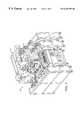
- FIG. 1is a perspective view of the optical inspection apparatus of the present invention.
- FIG. 1 ais an enlarged view of the Optical Inspection Assembly shown in FIG. 1 .
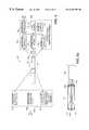
- FIG. 2is a block diagram of the optical inspection apparatus of FIG. 1 .
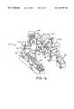
- FIG. 3is a perspective view of the Optical Inspection Assembly shown in FIG. 1 a.
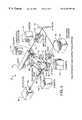
- FIG. 4is a block diagram of the Surface Inspection Assembly portion of the Optical Inspection Assembly shown in FIG. 3 .
- FIG. 5is a top view of the Optical Scanner and optics function in the Surface Inspection Assembly shown in FIG. 4 for transparent disks.
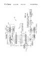
- FIG. 6is a block diagram of the Edge Inspection Assembly portion of the Optical Inspection Assembly shown in FIG. 3 .
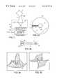
- FIG. 6 ais a cross-sectional view of the transparent disk shown in FIG. 6 showing how the waveguide properties of the transparent disk cause illumination of the inner edges with a light source shining on the outer edge.
- FIG. 7is a partial perspective view of one particular implementation of the outer radius inspection assembly shown in FIG. 6 using a camera having a linear CCD array.
- FIG. 8 ais a front view of the transparent disk shown in FIG. 3 showing the scanning in the r direction, and rotation of the disk in the theta direction.
- FIG. 8 bis an enlarged view of the scanned portion of FIG. 8 a showing how the combination of the linear travel of the beam and the rotation of the disk results in complete scanning of the entire surface of the disk.
- FIG. 9 ais a three dimensional representation of a typical Gaussian distribution of light intensity (amplitude).
- FIG. 9 bis a three dimensional representation of a typical Gaussian distribution of light phase.
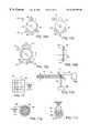
- FIG. 10 ais an elevational view of the disk of FIG. 3 showing the roller configuration which rotates the disk during inspection.
- FIG. 10 bis an elevational view of the disk and rollers of FIG. 10 a showing how the top roller moves to facilitate loading and unloading of the disk by the Automatic Disk Handler.
- FIG. 10 cis an elevational view of the disk and rollers of FIG. 10 b showing how the movement of the roller shown in FIG. 10 b and the operation of the lifter allow the Automatic Disk Handler to load and unload the disk into the apparatus of FIG. 3 .
- FIG. 10 dis a side view of two of the rollers and the disk shown in FIG. 10 a taken along the line 10 d — 10 d showing the slot in the rollers for holding the disk in place during rotation.
- FIG. 11is a front view of one specific configuration of the Parallel Detector Array which detects changes in the amplitude and/or phase of the Optical Scanner beam.
- FIG. 11 ais a front view of another specific configuration of the Parallel Detector Array which detects changes in the amplitude and/or phase of the Optical Scanner beam.
- FIG. 11 bis a top view of the optics function of an alternative parallel detection configuration which detects changes in the amplitude and/or phase of the Optical Scanner beam.
- FIG. 11 cis a front view of another specific configuration of the Parallel Detector Array which detects changes in the amplitude and/or phase of the Optical Scanner beam.
- FIG. 12is a flow chart of the control software operation for the apparatus of the present invention.
- FIG. 1shows the optical inspection apparatus 40 of the present invention, comprising an IBM compatible PC-AT computer 46 or equivalent, a keyboard 48 , a color monitor 50 , an operator panel 56 , an Optical Inspection Assembly 52 located on table 54 , and an Automatic Disk Handler 42 (typically a robot) to automatically load and unload the disk to be inspected ( 44 , 74 , and 47 ) into the Optical Inspection Assembly 52 .
- FIG. 1 ais an enlarged view of the Optical Inspection Assembly 52 of FIG. 1 .
- FIG. 2is the block diagram of the apparatus 40 of the present invention, with numbers that correspond to numbers in FIG. 1 representing the same components. The apparatus shown in FIG.
- the Optical Inspection Assembly 52comprises a Disk Movement Driver 62 , a Disk Movement Actuator 64 , a Surface Inspection Assembly 66 , an Edge Inspection Assembly 68 , and a Transparent Disk 74 .
- the Automatic Disk Handler 42first loads the Transparent Disk 74 into the Optical Inspection Assembly 52 .
- the Surface Inspection Assembly 66then begins its scan of the surface of the Transparent Disk 74 .
- the Edge Inspection Assembly 68begins inspection of the inner and outer edges of the Transparent Disk 74 .
- Both the Surface Inspection Assembly 66 and the Edge Inspection Assembly 68perform only a linear inspection, and thus depend on the Disk Movement Actuator 64 to rotate the Transparent Disk 74 such that the entire surface is inspected by the Surface Inspection Assembly 66 , and such that the entire edge is inspected by the Edge Inspection Assembly 68 .
- the Surface Inspection Assembly 66 and the Edge Inspection Assembly 68both have programmable thresholds that determine the characteristics of allowable defects. If either of these assemblies detects a defect greater than the programmed threshold, a fault signal is sent to the computer 46 to indicate that the inspection failed.
- the computer 46causes the Automatic Disk Handler 42 to place good disks (those that pass inspection) in one place, and to place bad disks (those that fail inspection) in a different place. In a fully automated system, an automated cart or conveyer would deliver uninspected disks and take away both good and bad inspected disks as the apparatus 40 requires.
- the Optical Inspection Assembly 52is shown in FIG. 3.
- a laser 70provides the light beam 72 used to inspect the Transparent Disk 74 .
- the laser 70must have a minimum spatial and temporal coherence greater than the defects to be measured.
- the coherence of the laser 70is related to its optical Signal to Noise (S/N) ratio, while the power of the laser 70 is related to its electrical S/N ratio.
- the light beam 72passes through Filter Optics 76 , which increases the spatial coherence of the beam 72 and shapes and directs the beam 72 to the mirror 78 , which directs the beam 72 to an aperture 69 on Optical Scanner 80 .
- the aperture 69 on Optical Scanner 80is shown in FIG. 1 a . Referring again to FIG.
- Optical Scanner 80has a rotating polygonal head 82 with reflective faces.
- the beam 72passes through the aperture (not shown in FIG. 3) onto the rotating polygonal head 82 , which causes the beam 72 to sweep across the Scanning Optics 84 . If the polygonal head 82 rotates clockwise as shown, the sweep of the beam 72 will be from left to right on the Transparent Disk 74 .
- the Scanning Optics 84are placed at the precise distance from the polygonal head 82 of Optical Scanner 80 defined by the focal length of the Scanning Optics 84 .
- the Transparent Disk 74is placed at this same distance from the Scanning Optics 84 , such that the focal point of the beam 72 is at the exact center of Transparent Disk 74 .
- the beam 72diverges and contacts Detection Optics 86 , which is placed at a distance from the Transparent Disk 74 that corresponds to its focal length.
- the Detection Optics 86cause each point along the beam scan to project on the Parallel Detector Array 88 within Detector 90 , which is also placed at a distance from the Detection Optics 86 that corresponds to the focal length of Detection Optics 86 .
- FIG. 11One specific implementation of the Parallel Detector Array 88 is shown in FIG. 11 .
- An array of light sensitive devices 94is provided, typically a photodiode array. Each light sensitive device 94 provides an electrical signal proportional to the intensity of light it detects.
- a nominal beam spot 92is shown, which is smaller than the matrix as shown.
- This type of a spot 92 of laser light on Parallel Detector Array 88causes a two-dimensional response with respect to intensity or amplitude, which is represented in FIG. 9 a .
- this type of spot 92causes a two-dimensional response with respect to changes of phase, which is represented in FIG. 9 b .
- the changes of phasewill create an interference pattern between the center and outer rim of the beam 72 , causing a change in the ideal Gaussian distribution.
- the light sensitive devices 94 of Parallel Detector Array 88could also be an array of CCDs, and could be arranged in any physical configuration, such as circular or concentric rings of individual detectors, as shown in FIG. 11 a .
- two concentric ring detectors in the configuration shown in FIG. 11 ccould be used to form Parallel Detector Array 88 .
- Detector 94 adetects the center portion of the beam, while detector 94 b detects the outer portion of the beam, which has nominal spot size 92 as shown.
- FIG. 11 bshows an alternative arrangement which uses two Parallel Detector Arrays 88 .
- Beam 72has a nominal spot size 92 as shown.
- Beam 72is projected onto a transparent substrate 87 which has a small reflective portion 89 , and is positioned at a 45 degree angle with respect to the beam 72 as shown.
- the center portion 85 of beam 72is reflected off the reflective portion 89 of transparent substrate 87 to a Parallel Detector Array 88 a as shown in the figure.
- the outer portion 83 of the beam 72passes through the transparent substrate 87 onto a second Parallel Detector Array 88 b .
- the two Parallel Detector Arrays 88 a and 88 bact in parallel to detect any change in the nominal Gaussian distribution of light within beam 72 .
- Parallel Detector Arrays 88 a and 88 b shown in FIG. 11 bcould be replaced with a single detector, since the two detectors 88 a and 88 b act in parallel, and can therefore detect with only two sensors changes in the nominal Gaussian distribution of the beam 72 . Neither the number, type of device used nor the physical arrangement of these devices is critical to this invention.
- the primary inventive feature regarding the Parallel Detector Array 88is the use of more than one optical detector in parallel to detect changes in a nominally Gaussian distribution of light within the spot of the optical beam 72 .
- the apparatus 40 of the present inventionhas a much higher resolution than prior art optical inspection systems, which are limited by the diffraction limits of the optics and specific configuration of the system.
- the apparatus 40measures changes in the electromagnetic fields in a general point in space, which therefore removes the classical diffraction limit experienced by prior art systems. Since the Parallel Detector Array 88 can detect changes in both phase and amplitude of the nominal Gaussian distribution of light (phase changes are detected by interference between the center and rim of the beam), a change in the surface characteristics caused by even a very narrow or shallow defect will interfere with the rest of the field, and will be detected.
- the lateral resolution of the apparatus 40allows the lateral resolution of the apparatus 40 to be from 100 to 1000 times greater than the diffraction limit, since phase changes are detected as well as amplitude changes.
- the longitudinal sensitivity within the diffraction limitis interferometric, while the adjustment sensitivity is only dependent on the depth of field.
- rollers 96 , 98 and 100comprise the Disk Movement Actuator 64 shown in FIG. 2 . Only one of these three rollers 96 , 98 and 100 are motor-driven, with the computer 46 controlling the motor drive through communicating with the Disk Movement Driver 62 as shown in FIG. 2 .
- roller 96is the one roller that is driven by a motor, and that it rotates in a clockwise direction as shown.
- the computer 46causes roller 96 to rotate clockwise, which causes Transparent Disk 74 to rotate counter-clockwise. In this manner the entire surface of Transparent Disk 74 is scanned when it has rotated one revolution.
- FIG. 3shows a lifter 99 , which acts in conjunction with the Automatic Disk Handler 42 (not shown) to load untested disks into the Optical Inspection Assembly 52 and to unload tested disks from the Optical Inspection Assembly 52 .
- the detailed operation of the loading and unloading functioncan be best understood in reference to FIG. 10 a-c .
- FIG. 10 ashows a Transparent Disk 74 while it is being rotated under test by rollers 96 , 98 and 100 .
- Lifter 99is positioned away from the Transparent Disk 74 during testing.
- the computer 46stops driving roller 96 , causing the rotation of the rollers 96 , 98 and 100 to stop.
- the computer 46then moves the roller 98 out of the way as shown in FIG. 10 b .
- the Gripping Arm 101 of Automatic Disk Handler 42is placed into the proper position, and lifter 99 then lifts the Transparent Disk 74 away from rollers 96 and 98 , to a position where Gripping Arm 101 can close and thereby grip the Transparent Disk 74 , as shown in FIG. 10 c .
- This processis reversed for loading disks into the Optical Inspection Assembly 52 .
- FIG. 10 cThis process is reversed for loading disks into the Optical Inspection Assembly 52 .
- 10 dshows a side view of the rollers 98 and 100 and the Transparent Disk 74 shown in FIG. 10 a , illustrating the narrow slots or “V” grooves 103 used to hold the Transparent Disk 74 in the proper position on the rollers 96 , 98 and 100 .
- FIG. 4shows the configuration of the Surface Inspection Assembly 66 shown in FIG. 2 used in the Optical Inspection Assembly 52 . Note that many of the numbers in FIG. 4 correspond to components shown in FIG. 3 .
- the laser 70is powered by a Laser Power Supply 71 , and provides beam 72 , which passes through Filter Optics 76 .
- the mirror 78 of FIG. 3is not shown in FIG. 4 .
- the light beam 72contacts the Optical Scanner 80 , which provides a linear scanning action of the beam 72 across Trigger Detector 73 and Scanning Optics 84 .
- Trigger Detector 73is placed at the beginning position of the scan path of beam 72 , and provides an electrical SYNC signal to the computer 46 when the beam 72 contacts it to synchronize the sweep of beam 72 with the rotation of the Transparent Disk 74 and the output of Detector 90 .
- the Optical Scanner 80can be switched on or off by the computer 46 giving the appropriate command to the Scanner Motor Driver 51 , which controls the Scanner Motor 53 .
- the Trigger Detector 73can be mounted anywhere within the scan path of beam 72 . In the configuration illustrated in the figures, Trigger Detector 73 is mounted on the side of the Scanning Optics 84 .
- the Trigger Detector 73could, in the alternative, be placed in the scan path of beam 72 next to the Transparent Disk 74 . By placing the Trigger Detector 73 next to the Scanning Optics 84 , no optic field of Scanning Optics 84 is taken by Trigger Detector 73 .
- the angle sweep of Optical Scanner 80is converted by the Scanning Optics 84 to a sweep of parallel beams, each contacting the Transparent Disk 74 normal to its surface.
- the beam 72continues through the Transparent Disk 74 to Detection Optics 86 , which directs each beam to the Parallel Detector Array 88 within Detector 90 .
- the nominal Gaussian output of Parallel Detector Array 88is processed by analog circuitry in the Analog Process block 91 , which is powered by Power Supply 97 .
- Analog Process 91receives a threshold control signal 95 from the computer 46 and detects any change in the Gaussian distribution of beam 72 which corresponds to a defect greater than the programmed threshold.
- the Analog Process 91signals the computer 46 that the inspection failed by asserting a Fault signal 93 .
- the computer 46will then nominally abort the inspection of the Transparent Disk 74 , and cause the failed disk to be placed in the area of bad disks by the Automatic Disk Handler 42 .
- FIG. 5clearly represents the operation of the Scanning Optics 84 and the Detection Optics 86 .
- the beam 72is reflected off the Optical Scanner 80 , and first contacts the Trigger Detector 73 , then continues to scan across the Scanning Optics 84 .
- Beam 72first comes in contact with Scanning Optics 84 on the left side of the Scanning Optics 84 , as represented by 72 A in FIG. 5 .
- Scanning Optics 84focuses the beam to a small spot at the exact center of the Transparent Disk 74 as shown. After passing through the focal point at the center of the Transparent Disk 74 , the beam 72 A begins to diverge.
- the beam 72 Athen contacts Detection Optics 86 , which directs the beam 72 A to the Parallel Detector Array 88 within Detector 90 .
- Optional Detection Optics 81may be used to magnify the beam 72 , to correct for wandering of beam 72 , or for other purposes as required.
- the Optical Scanner beam 72continues its sweep, it will come to the position shown by 72 B, and eventually to the position shown by 72 C. Note that for each position of the beam 72 , a different spot on the Transparent Disk 74 is in the path of the beam 72 , and the resulting beam is projected onto the Parallel Detector Array 88 as shown. Note that this method can only be accomplished by placing the Optical Scanner 80 at a distance d from Scanning optics 84 equal to the focal length of Scanning Optics 84 . The center of the Transparent Disk 74 is located at this same distance from the Scanning Optics 84 .
- Detection Optics 86is located this same distance from the center of the Transparent Disk 74
- the Parallel Detector Array 88is located this same distance from the Detection Optics 86 .
- the size of the beam 72 at the Optical Scanner 80is nominally the same size as the beam 72 at the Parallel Detector Array 88 .
- the Edge Inspection Assembly 68is comprised of an Outer Radius Inspection Assembly 128 and an Inner Radius Inspection Assembly 130 .
- a Power Supply 102powers a light source 104 , which passes through Projection Optics 106 to the outer edge of the Transparent Disk 74 as shown.
- Each disknominally has two beveled edges 108 and 110 and a flat edge 109 on its outer edge as shown, and two beveled edges 112 and 114 and a flat edge 113 on its inner edge as shown.
- beveled edge 108 and half of flat edge 109are inspected by Detector Optics #1 116
- beveled edge 110 and the other half of flat edge 109are inspected by Detector Optics #2 118
- beveled edge 112 and flat edge 113are inspected by Detector Optics #3 120
- beveled edge 114 and the other half of flat edge 113is inspected by Detector Optics #4 122 .
- Detector Optics #1 116 and Detector Optics #2 118project the image of the edge to be inspected onto detectors, the outputs of which are processed to determine if any defects occur greater than a programmable threshold. This detection and process step is represented by the Detectors and Process block 124 . Likewise Detector Optics #3 120 and Detector Optics #4 122 go to a Detectors and Process block 126 . Any defect in either the Outer Radius Inspection Assembly 128 or the Inner Radius Inspection Assembly 130 above their respective programmable thresholds is reported to the computer 46 as a fault, which causes the disk inspection to fail.
- FIG. 6 aillustrates how the single light source 104 within the Outer Radius Inspection Assembly 128 can be used to illuminate both the outer edges ( 108 , 109 and 110 ) and the inner edges ( 112 , 113 and 114 ) of the Transparent Disk 74 simultaneously.
- the light sourceshines through Projection Optics 106 , which illuminates the outer edge of the Transparent Disk 74 as shown. Due to the transparency of Transparent Disk 74 , the light that shines onto the outer edge of the Transparent Disk 74 is transmitted through the transparent disk medium to the inner edges 112 , 113 and 114 .
- FIG. 6 ashows how the Transparent Disk 74 acts as a wave guide, directing the transmitted light to the inner edges of the disk.
- This featureallows for simultaneous illumination and inspection of both the inner edges ( 112 , 113 and 114 ) and the outer edges ( 108 , 109 and 110 ) with only one light source. This is significant since the addition of a second light source to inspect the inner edges would add to the expense and complexity of the apparatus 40 , since this second light source would have to be positioned after the Transparent Disk 74 is loaded for testing, and removed prior to the Transparent Disk 74 being unloaded after testing.
- Projection Optics 106is a fiberoptic strand as represented in FIG. 3 .
- Each of the Detector Optics 116 , 118 , 120 and 122are digital CCD cameras in the first embodiment shown in FIG. 3.
- a detailed view of the operation of one of the digital CCD camerasis shown in FIG. 7 .
- inspection of edge 110 and half of edge 109 of the Transparent Disk 74is shown.
- the digital CCD camera 132has a single row of CCDS, known as a Linear CCD Array 136 .
- the image of the edge 110 and the half of edge 109 of the Transparent Disk 74 to be inspectedis focused by the lens 134 of the camera 132 onto the Linear CCD Array 136 as shown.
- the Processing Electronics 138then processes the outputs from the Linear CCD Array 136 and asserts a fault signal to the computer 46 if a defect above a programmable threshold value exists.
- the Linear CCD Array 136only detects a small portion of the edges as shown in FIG. 7, but the rotation of the disk for one revolution during inspection allows the camera 132 to inspect the entire edge during that one revolution. This occurs simultaneously for all edges 108 , 109 , 110 , 112 , 113 and 114 shown in FIG. 6, and occurs simultaneously with the inspection of the surface of the Transparent Disk 74 by the Surface Inspection Assembly 66 .
- Each inspection assembly in the apparatus 40 of the present inventionhas its own programmable threshold above which a fault will be signaled, causing the disk inspection to fail.
- the computer 46only has to load the disk, rotate the disk, and monitor the outputs of each inspection assembly for faults. If a fault is signaled to the computer 46 prior to a full revolution being completed, the inspection fails and the disk is unloaded by the Automatic Disk Handler 42 and placed in the place for “bad” disks. If the computer 46 completes a full rotation of the disk with no fault signal from any of the inspection assemblies, the disk passes the inspection and is unloaded by the Automatic Disk Handler 42 and placed in the place for “good” disks.
- FIG. 8 a and 8 billustrate how the combination of the scanning of the beam 72 and the rotation of the Transparent Disk 74 provide for a complete inspection of the entire surface of the Transparent Disk 74 .
- the beam 72scans in a line from left to right as shown by the r direction.
- the diskrotates in the theta direction shown in the figure.
- the diskis inspected in polar coordinates, with the r coordinate representing the position of the beam 72 in its scan path, and the theta coordinate representing the rotational position of the Transparent Disk 74 .
- the effect of this polar scanning techniqueis shown in FIG. 8 b.
- the beamis configured to scan along a radius of the Transparent Disk 74 , from left to right as shown.
- the beamhas a spot size which travels along this scan path.
- the beam 72In order for the beam 72 to completely scan the entire surface of the Transparent Disk 74 , the beam 72 must overlap somewhat with the previous scan path. Due to the circular configuration of the disk the outside circumference is significantly greater than the inside circumference, so a rotational change of position causes the outer edge to travel a farther distance than the inner edge. This means that the spot must overlap slightly on the outer edge 140 of the disk, which causes a much greater overlap on the inner edge 142 of the disk, as shown in FIG. 10 b . This difference in overlap between the beam at the outer edge 140 and the inner edge 142 of the Transparent Disk 74 can be corrected using electronics or software to provide for accurate mapping of disk defects.
- FIG. 12The flow chart of the program flow of the control software within computer 46 is shown in FIG. 12 .
- the specific implementation shown in FIG. 12assumes that the computer 46 will poll the Surface Inspection Assembly 66 and the Edge Inspection Assembly 68 to determine whether a defect is reported by either of these assemblies.
- the fault output 93 of the Surface Inspection Assembly 66 and the fault output 93 of the Edge Inspection Assembly 68are interrupt-driven inputs to computer 46 , which report a fault by interrupting program execution of the computer 46 .
- the computer 46simply completes the rotation of the disk, then checks a software flag to determine whether a fault was detected during the scan.
- the automation of apparatus 40provided by computer 46 and Automatic Disk Handler 42 provides for high-speed inspection of apparatus 40 , which suits the apparatus 40 well to a speed sensitive production environment.
Landscapes
- Physics & Mathematics (AREA)
- Health & Medical Sciences (AREA)
- Life Sciences & Earth Sciences (AREA)
- Chemical & Material Sciences (AREA)
- Analytical Chemistry (AREA)
- Biochemistry (AREA)
- General Health & Medical Sciences (AREA)
- General Physics & Mathematics (AREA)
- Immunology (AREA)
- Pathology (AREA)
- Investigating Materials By The Use Of Optical Means Adapted For Particular Applications (AREA)
Abstract
Description
Claims (101)
Priority Applications (1)
| Application Number | Priority Date | Filing Date | Title |
|---|---|---|---|
| US07/985,631US6294793B1 (en) | 1992-12-03 | 1992-12-03 | High speed optical inspection apparatus for a transparent disk using gaussian distribution analysis and method therefor |
Applications Claiming Priority (1)
| Application Number | Priority Date | Filing Date | Title |
|---|---|---|---|
| US07/985,631US6294793B1 (en) | 1992-12-03 | 1992-12-03 | High speed optical inspection apparatus for a transparent disk using gaussian distribution analysis and method therefor |
Publications (1)
| Publication Number | Publication Date |
|---|---|
| US6294793B1true US6294793B1 (en) | 2001-09-25 |
Family
ID=25531652
Family Applications (1)
| Application Number | Title | Priority Date | Filing Date |
|---|---|---|---|
| US07/985,631Expired - Fee RelatedUS6294793B1 (en) | 1992-12-03 | 1992-12-03 | High speed optical inspection apparatus for a transparent disk using gaussian distribution analysis and method therefor |
Country Status (1)
| Country | Link |
|---|---|
| US (1) | US6294793B1 (en) |
Cited By (64)
| Publication number | Priority date | Publication date | Assignee | Title |
|---|---|---|---|---|
| US20030107730A1 (en)* | 2001-12-06 | 2003-06-12 | Byoung-Sam Kim | Micro-bubble analyzing apparatus for high-purity glass tube using laser light scattering |
| US6742707B1 (en)* | 2000-06-07 | 2004-06-01 | Metrologic Instruments, Inc. | Method of speckle-noise pattern reduction and apparatus therefor based on reducing the spatial-coherence of the planar laser illumination beam before the beam illuminates the target object by applying spatial phase shifting techniques during the transmission of the plib theretowards |
| US20040196454A1 (en)* | 2003-04-03 | 2004-10-07 | Takayuki Ishiguro | Optical system, detector and method for detecting peripheral surface defect of translucent disk |
| US20050024630A1 (en)* | 2003-04-28 | 2005-02-03 | Renesas Technology Corp. | Device for examining end part |
| US20050062960A1 (en)* | 2001-09-19 | 2005-03-24 | Olympus Optical Co., Ltd. | Semiconductor wafer inspection apparatus |
| US20060221333A1 (en)* | 2003-03-04 | 2006-10-05 | Junichi Matsumoto | Inspection device for transparent substrate end surface and inspection method therefor |
| US20070131880A1 (en)* | 2005-09-02 | 2007-06-14 | Richardson Ric B | Method and apparatus for using imperfections and irregularities in optical media for identification purposes |
| US20070143844A1 (en)* | 2005-09-02 | 2007-06-21 | Richardson Ric B | Method and apparatus for detection of tampering attacks |
| US20070222977A1 (en)* | 2004-11-30 | 2007-09-27 | Shibaura Mechatronics Corporation | Surface inspection apparatus and surface inspection method |
| US20070222975A1 (en)* | 2006-03-24 | 2007-09-27 | Shigeru Serikawa | Testing method for surface defects on disc and testing apparatus for the same |
| US20080024773A1 (en)* | 2006-07-31 | 2008-01-31 | Yusuke Miyazaki | Surface inspection apparatus and surface inspection method |
| US20080088830A1 (en)* | 2006-10-16 | 2008-04-17 | Shigeru Serikawa | Optical system of detecting peripheral surface defect of glass disk and device of detecting peripheral surface defect thereof |
| US20080128509A1 (en)* | 2000-11-24 | 2008-06-05 | Knowles C Harry | Digital image capturing and processing system for automatically recognizing objects in a POS environment |
| US20080320607A1 (en)* | 2007-06-21 | 2008-12-25 | Uniloc Usa | System and method for auditing software usage |
| US20090083730A1 (en)* | 2007-09-20 | 2009-03-26 | Richardson Ric B | Installing Protected Software Product Using Unprotected Installation Image |
| US20090150674A1 (en)* | 2007-12-05 | 2009-06-11 | Uniloc Corporation | System and Method for Device Bound Public Key Infrastructure |
| US20090217384A1 (en)* | 2008-02-22 | 2009-08-27 | Etchegoyen Craig S | License Auditing for Distributed Applications |
| US20090292816A1 (en)* | 2008-05-21 | 2009-11-26 | Uniloc Usa, Inc. | Device and Method for Secured Communication |
| US20090327070A1 (en)* | 2008-06-25 | 2009-12-31 | Uniloc Usa, Inc. | System and Method for Monitoring Efficacy of Online Advertising |
| US20100229224A1 (en)* | 2009-02-10 | 2010-09-09 | Uniloc Usa, Inc. | Web Content Access Using a Client Device Identifier |
| US20100257214A1 (en)* | 2009-03-18 | 2010-10-07 | Luc Bessette | Medical records system with dynamic avatar generator and avatar viewer |
| US7832643B2 (en) | 1998-03-24 | 2010-11-16 | Metrologic Instruments, Inc. | Hand-supported planar laser illumination and imaging (PLIIM) based systems with laser despeckling mechanisms integrated therein |
| US20100312702A1 (en)* | 2009-06-06 | 2010-12-09 | Bullock Roddy M | System and method for making money by facilitating easy online payment |
| US20100325711A1 (en)* | 2009-06-23 | 2010-12-23 | Craig Stephen Etchegoyen | System and Method for Content Delivery |
| US20100325424A1 (en)* | 2009-06-19 | 2010-12-23 | Etchegoyen Craig S | System and Method for Secured Communications |
| US20100325735A1 (en)* | 2009-06-22 | 2010-12-23 | Etchegoyen Craig S | System and Method for Software Activation |
| US20100325025A1 (en)* | 2009-06-22 | 2010-12-23 | Etchegoyen Craig S | System and Method for Sharing Media |
| US20100324989A1 (en)* | 2009-06-23 | 2010-12-23 | Craig Stephen Etchegoyen | System and Method for Monitoring Efficacy of Online Advertising |
| US20100325040A1 (en)* | 2009-06-23 | 2010-12-23 | Craig Stephen Etchegoyen | Device Authority for Authenticating a User of an Online Service |
| US20100325149A1 (en)* | 2009-06-22 | 2010-12-23 | Craig Stephen Etchegoyen | System and Method for Auditing Software Usage |
| US20100325431A1 (en)* | 2009-06-19 | 2010-12-23 | Joseph Martin Mordetsky | Feature-Specific Keys for Executable Code |
| US20100325051A1 (en)* | 2009-06-22 | 2010-12-23 | Craig Stephen Etchegoyen | System and Method for Piracy Reduction in Software Activation |
| US20100321208A1 (en)* | 2009-06-23 | 2010-12-23 | Craig Stephen Etchegoyen | System and Method for Emergency Communications |
| US20100325423A1 (en)* | 2009-06-22 | 2010-12-23 | Craig Stephen Etchegoyen | System and Method for Securing an Electronic Communication |
| US20100324981A1 (en)* | 2009-06-22 | 2010-12-23 | Etchegoyen Craig S | System and Method for Media Distribution on Social Networks |
| US20100325446A1 (en)* | 2009-06-19 | 2010-12-23 | Joseph Martin Mordetsky | Securing Executable Code Integrity Using Auto-Derivative Key |
| US20100325200A1 (en)* | 2009-06-22 | 2010-12-23 | Craig Stephen Etchegoyen | System and Method for Software Activation Through Digital Media Fingerprinting |
| US20100332331A1 (en)* | 2009-06-24 | 2010-12-30 | Craig Stephen Etchegoyen | Systems and Methods for Providing an Interface for Purchasing Ad Slots in an Executable Program |
| US20100332337A1 (en)* | 2009-06-25 | 2010-12-30 | Bullock Roddy Mckee | Universal one-click online payment method and system |
| US20100333081A1 (en)* | 2009-06-24 | 2010-12-30 | Craig Stephen Etchegoyen | Remote Update of Computers Based on Physical Device Recognition |
| US20100332267A1 (en)* | 2009-06-24 | 2010-12-30 | Craig Stephan Etchegoyen | System and Method for Preventing Multiple Online Purchases |
| US20100333207A1 (en)* | 2009-06-24 | 2010-12-30 | Craig Stephen Etchegoyen | Systems and Methods for Auditing Software Usage Using a Covert Key |
| US20100332396A1 (en)* | 2009-06-24 | 2010-12-30 | Craig Stephen Etchegoyen | Use of Fingerprint with an On-Line or Networked Auction |
| US20100332319A1 (en)* | 2009-06-24 | 2010-12-30 | Craig Stephen Etchegoyen | Methods and Systems for Dynamic Serving of Advertisements in a Game or Virtual Reality Environment |
| US20110010560A1 (en)* | 2009-07-09 | 2011-01-13 | Craig Stephen Etchegoyen | Failover Procedure for Server System |
| US20110009092A1 (en)* | 2009-07-08 | 2011-01-13 | Craig Stephen Etchegoyen | System and Method for Secured Mobile Communication |
| US20110093474A1 (en)* | 2009-10-19 | 2011-04-21 | Etchegoyen Craig S | System and Method for Tracking and Scoring User Activities |
| US20110093920A1 (en)* | 2009-10-19 | 2011-04-21 | Etchegoyen Craig S | System and Method for Device Authentication with Built-In Tolerance |
| US20110093701A1 (en)* | 2009-10-19 | 2011-04-21 | Etchegoyen Craig S | Software Signature Tracking |
| US20110093503A1 (en)* | 2009-10-19 | 2011-04-21 | Etchegoyen Craig S | Computer Hardware Identity Tracking Using Characteristic Parameter-Derived Data |
| US8103553B2 (en) | 2009-06-06 | 2012-01-24 | Bullock Roddy Mckee | Method for making money on internet news sites and blogs |
| US8284929B2 (en) | 2006-09-14 | 2012-10-09 | Uniloc Luxembourg S.A. | System of dependant keys across multiple pieces of related scrambled information |
| US8423473B2 (en) | 2009-06-19 | 2013-04-16 | Uniloc Luxembourg S. A. | Systems and methods for game activation |
| US8438394B2 (en) | 2011-01-14 | 2013-05-07 | Netauthority, Inc. | Device-bound certificate authentication |
| US8566960B2 (en) | 2007-11-17 | 2013-10-22 | Uniloc Luxembourg S.A. | System and method for adjustable licensing of digital products |
| US8613110B2 (en) | 2000-06-14 | 2013-12-17 | Uniloc Luxembourg S.A. | Software piracy prevention through remote enforcement of an activation threshold |
| US8726407B2 (en) | 2009-10-16 | 2014-05-13 | Deviceauthority, Inc. | Authentication of computing and communications hardware |
| US8736462B2 (en) | 2009-06-23 | 2014-05-27 | Uniloc Luxembourg, S.A. | System and method for traffic information delivery |
| US8903653B2 (en) | 2009-06-23 | 2014-12-02 | Uniloc Luxembourg S.A. | System and method for locating network nodes |
| US9047450B2 (en) | 2009-06-19 | 2015-06-02 | Deviceauthority, Inc. | Identification of embedded system devices |
| US9047458B2 (en) | 2009-06-19 | 2015-06-02 | Deviceauthority, Inc. | Network access protection |
| US20150233841A1 (en)* | 2013-12-23 | 2015-08-20 | Kla-Tencor Corporation | Multi-Channel Backside Wafer Inspection |
| US9633183B2 (en) | 2009-06-19 | 2017-04-25 | Uniloc Luxembourg S.A. | Modular software protection |
| CN110987927A (en)* | 2019-11-15 | 2020-04-10 | 南京大学 | Rotating object imaging system based on Laguerre Gaussian transformation |
Citations (8)
| Publication number | Priority date | Publication date | Assignee | Title |
|---|---|---|---|---|
| US3836261A (en)* | 1972-07-29 | 1974-09-17 | Ferranti Ltd | Device for detection of blemishes on opposite faces of a planar object |
| US3900265A (en)* | 1974-03-08 | 1975-08-19 | Intec Corp | Laser scanner flaw detection system |
| US4376583A (en)* | 1981-05-12 | 1983-03-15 | Aeronca Electronics, Inc. | Surface inspection scanning system |
| US4505585A (en)* | 1981-03-31 | 1985-03-19 | Olympus Optical Co., Ltd. | System for detecting defects on an optical surface |
| US4924086A (en)* | 1987-11-05 | 1990-05-08 | Erwin Sick Gmbh Optik-Elektronik | Optical scanning apparatus for detecting faults on a surface |
| US4954723A (en)* | 1988-06-13 | 1990-09-04 | Fuji Photo Film Co., Ltd. | Disk surface inspection method and apparatus therefor |
| US5031112A (en)* | 1988-06-08 | 1991-07-09 | Dai Nippon Insatsu Kabushiki Kaisha | System for detecting defective portions in data recording portions of optical recording medium |
| US5135305A (en)* | 1991-03-01 | 1992-08-04 | Thermo Jarrell Ash Corporation | Spectroanalytical system |
- 1992
- 1992-12-03USUS07/985,631patent/US6294793B1/ennot_activeExpired - Fee Related
Patent Citations (8)
| Publication number | Priority date | Publication date | Assignee | Title |
|---|---|---|---|---|
| US3836261A (en)* | 1972-07-29 | 1974-09-17 | Ferranti Ltd | Device for detection of blemishes on opposite faces of a planar object |
| US3900265A (en)* | 1974-03-08 | 1975-08-19 | Intec Corp | Laser scanner flaw detection system |
| US4505585A (en)* | 1981-03-31 | 1985-03-19 | Olympus Optical Co., Ltd. | System for detecting defects on an optical surface |
| US4376583A (en)* | 1981-05-12 | 1983-03-15 | Aeronca Electronics, Inc. | Surface inspection scanning system |
| US4924086A (en)* | 1987-11-05 | 1990-05-08 | Erwin Sick Gmbh Optik-Elektronik | Optical scanning apparatus for detecting faults on a surface |
| US5031112A (en)* | 1988-06-08 | 1991-07-09 | Dai Nippon Insatsu Kabushiki Kaisha | System for detecting defective portions in data recording portions of optical recording medium |
| US4954723A (en)* | 1988-06-13 | 1990-09-04 | Fuji Photo Film Co., Ltd. | Disk surface inspection method and apparatus therefor |
| US5135305A (en)* | 1991-03-01 | 1992-08-04 | Thermo Jarrell Ash Corporation | Spectroanalytical system |
Cited By (100)
| Publication number | Priority date | Publication date | Assignee | Title |
|---|---|---|---|---|
| US7832643B2 (en) | 1998-03-24 | 2010-11-16 | Metrologic Instruments, Inc. | Hand-supported planar laser illumination and imaging (PLIIM) based systems with laser despeckling mechanisms integrated therein |
| US7131586B2 (en) | 2000-06-07 | 2006-11-07 | Metrologic Instruments, Inc. | Method of and apparatus for reducing speckle-pattern noise in a planar laser illumination and imaging (PLIIM) based system |
| US6742707B1 (en)* | 2000-06-07 | 2004-06-01 | Metrologic Instruments, Inc. | Method of speckle-noise pattern reduction and apparatus therefor based on reducing the spatial-coherence of the planar laser illumination beam before the beam illuminates the target object by applying spatial phase shifting techniques during the transmission of the plib theretowards |
| US8613110B2 (en) | 2000-06-14 | 2013-12-17 | Uniloc Luxembourg S.A. | Software piracy prevention through remote enforcement of an activation threshold |
| US8172141B2 (en) | 2000-11-24 | 2012-05-08 | Metrologic Instruments, Inc. | Laser beam despeckling devices |
| US7793841B2 (en) | 2000-11-24 | 2010-09-14 | Metrologic Instruments, Inc. | Laser illumination beam generation system employing despeckling of the laser beam using high-frequency modulation of the laser diode current and optical multiplexing of the component laser beams |
| US20080142602A1 (en)* | 2000-11-24 | 2008-06-19 | Knowles C Harry | Laser illumination beam generation system employing despeckling of the laser beam using high-frequency modulation of the laser diode current and optical multiplexing of the component laser beams |
| US7784695B2 (en) | 2000-11-24 | 2010-08-31 | Metrologic Instruments, Inc. | Planar laser illumination module (PLIM) employing high-frequency modulation (HFM) of the laser drive currents and optical multplexing of the output laser beams |
| US7665665B2 (en)* | 2000-11-24 | 2010-02-23 | Metrologic Instruments, Inc. | Digital illumination and imaging subsystem employing despeckling mechanism employing high-frequency modulation of laser diode drive current and optical beam multiplexing techniques |
| US7806336B2 (en) | 2000-11-24 | 2010-10-05 | Metrologic Instruments, Inc. | Laser beam generation system employing a laser diode and high-frequency modulation circuitry mounted on a flexible circuit |
| US7806335B2 (en) | 2000-11-24 | 2010-10-05 | Metrologic Instruments, Inc. | Digital image capturing and processing system for automatically recognizing objects in a POS environment |
| US20080128509A1 (en)* | 2000-11-24 | 2008-06-05 | Knowles C Harry | Digital image capturing and processing system for automatically recognizing objects in a POS environment |
| US20050062960A1 (en)* | 2001-09-19 | 2005-03-24 | Olympus Optical Co., Ltd. | Semiconductor wafer inspection apparatus |
| US7102743B2 (en)* | 2001-09-19 | 2006-09-05 | Olympus Corporation | Semiconductor wafer inspection apparatus |
| US6822735B2 (en)* | 2001-12-06 | 2004-11-23 | Samsung Electronics Co., Ltd. | Micro-bubble analyzing apparatus for high-purity glass tube using laser light scattering |
| US20030107730A1 (en)* | 2001-12-06 | 2003-06-12 | Byoung-Sam Kim | Micro-bubble analyzing apparatus for high-purity glass tube using laser light scattering |
| US7289201B2 (en)* | 2003-03-04 | 2007-10-30 | Mitsuboshi Diamond Industrial Co., Ltd. | Inspection device for transparent substrate end surface and inspection method therefor |
| US20060221333A1 (en)* | 2003-03-04 | 2006-10-05 | Junichi Matsumoto | Inspection device for transparent substrate end surface and inspection method therefor |
| US20040196454A1 (en)* | 2003-04-03 | 2004-10-07 | Takayuki Ishiguro | Optical system, detector and method for detecting peripheral surface defect of translucent disk |
| US20050024630A1 (en)* | 2003-04-28 | 2005-02-03 | Renesas Technology Corp. | Device for examining end part |
| US7403278B2 (en)* | 2004-11-30 | 2008-07-22 | Shibaura Mechatronics Corporation | Surface inspection apparatus and surface inspection method |
| US20070222977A1 (en)* | 2004-11-30 | 2007-09-27 | Shibaura Mechatronics Corporation | Surface inspection apparatus and surface inspection method |
| US8087092B2 (en) | 2005-09-02 | 2011-12-27 | Uniloc Usa, Inc. | Method and apparatus for detection of tampering attacks |
| US7804079B2 (en)* | 2005-09-02 | 2010-09-28 | Uniloc Usa, Inc. | Method and apparatus for using imperfections and irregularities in optical media for identification purposes |
| US20070143844A1 (en)* | 2005-09-02 | 2007-06-21 | Richardson Ric B | Method and apparatus for detection of tampering attacks |
| US20070131880A1 (en)* | 2005-09-02 | 2007-06-14 | Richardson Ric B | Method and apparatus for using imperfections and irregularities in optical media for identification purposes |
| US20070222975A1 (en)* | 2006-03-24 | 2007-09-27 | Shigeru Serikawa | Testing method for surface defects on disc and testing apparatus for the same |
| US20080024773A1 (en)* | 2006-07-31 | 2008-01-31 | Yusuke Miyazaki | Surface inspection apparatus and surface inspection method |
| US8284929B2 (en) | 2006-09-14 | 2012-10-09 | Uniloc Luxembourg S.A. | System of dependant keys across multiple pieces of related scrambled information |
| US20080088830A1 (en)* | 2006-10-16 | 2008-04-17 | Shigeru Serikawa | Optical system of detecting peripheral surface defect of glass disk and device of detecting peripheral surface defect thereof |
| US7908662B2 (en) | 2007-06-21 | 2011-03-15 | Uniloc U.S.A., Inc. | System and method for auditing software usage |
| US20080320607A1 (en)* | 2007-06-21 | 2008-12-25 | Uniloc Usa | System and method for auditing software usage |
| US8671060B2 (en) | 2007-09-20 | 2014-03-11 | Uniloc Luxembourg, S.A. | Post-production preparation of an unprotected installation image for downloading as a protected software product |
| US8160962B2 (en) | 2007-09-20 | 2012-04-17 | Uniloc Luxembourg S.A. | Installing protected software product using unprotected installation image |
| US20090083730A1 (en)* | 2007-09-20 | 2009-03-26 | Richardson Ric B | Installing Protected Software Product Using Unprotected Installation Image |
| US8566960B2 (en) | 2007-11-17 | 2013-10-22 | Uniloc Luxembourg S.A. | System and method for adjustable licensing of digital products |
| US8464059B2 (en) | 2007-12-05 | 2013-06-11 | Netauthority, Inc. | System and method for device bound public key infrastructure |
| US20090150674A1 (en)* | 2007-12-05 | 2009-06-11 | Uniloc Corporation | System and Method for Device Bound Public Key Infrastructure |
| US8374968B2 (en) | 2008-02-22 | 2013-02-12 | Uniloc Luxembourg S.A. | License auditing for distributed applications |
| US20090217384A1 (en)* | 2008-02-22 | 2009-08-27 | Etchegoyen Craig S | License Auditing for Distributed Applications |
| US20090292816A1 (en)* | 2008-05-21 | 2009-11-26 | Uniloc Usa, Inc. | Device and Method for Secured Communication |
| US8812701B2 (en) | 2008-05-21 | 2014-08-19 | Uniloc Luxembourg, S.A. | Device and method for secured communication |
| US20090327070A1 (en)* | 2008-06-25 | 2009-12-31 | Uniloc Usa, Inc. | System and Method for Monitoring Efficacy of Online Advertising |
| US20100229224A1 (en)* | 2009-02-10 | 2010-09-09 | Uniloc Usa, Inc. | Web Content Access Using a Client Device Identifier |
| US8838976B2 (en) | 2009-02-10 | 2014-09-16 | Uniloc Luxembourg S.A. | Web content access using a client device identifier |
| US20100257214A1 (en)* | 2009-03-18 | 2010-10-07 | Luc Bessette | Medical records system with dynamic avatar generator and avatar viewer |
| US8103553B2 (en) | 2009-06-06 | 2012-01-24 | Bullock Roddy Mckee | Method for making money on internet news sites and blogs |
| US20100312702A1 (en)* | 2009-06-06 | 2010-12-09 | Bullock Roddy M | System and method for making money by facilitating easy online payment |
| US20100325431A1 (en)* | 2009-06-19 | 2010-12-23 | Joseph Martin Mordetsky | Feature-Specific Keys for Executable Code |
| US8423473B2 (en) | 2009-06-19 | 2013-04-16 | Uniloc Luxembourg S. A. | Systems and methods for game activation |
| US20100325446A1 (en)* | 2009-06-19 | 2010-12-23 | Joseph Martin Mordetsky | Securing Executable Code Integrity Using Auto-Derivative Key |
| US9047450B2 (en) | 2009-06-19 | 2015-06-02 | Deviceauthority, Inc. | Identification of embedded system devices |
| US9047458B2 (en) | 2009-06-19 | 2015-06-02 | Deviceauthority, Inc. | Network access protection |
| US9633183B2 (en) | 2009-06-19 | 2017-04-25 | Uniloc Luxembourg S.A. | Modular software protection |
| US20100325424A1 (en)* | 2009-06-19 | 2010-12-23 | Etchegoyen Craig S | System and Method for Secured Communications |
| US10489562B2 (en) | 2009-06-19 | 2019-11-26 | Uniloc 2017 Llc | Modular software protection |
| US8495359B2 (en) | 2009-06-22 | 2013-07-23 | NetAuthority | System and method for securing an electronic communication |
| US20100325025A1 (en)* | 2009-06-22 | 2010-12-23 | Etchegoyen Craig S | System and Method for Sharing Media |
| US20100325735A1 (en)* | 2009-06-22 | 2010-12-23 | Etchegoyen Craig S | System and Method for Software Activation |
| US20100325149A1 (en)* | 2009-06-22 | 2010-12-23 | Craig Stephen Etchegoyen | System and Method for Auditing Software Usage |
| US20100325051A1 (en)* | 2009-06-22 | 2010-12-23 | Craig Stephen Etchegoyen | System and Method for Piracy Reduction in Software Activation |
| US20100325423A1 (en)* | 2009-06-22 | 2010-12-23 | Craig Stephen Etchegoyen | System and Method for Securing an Electronic Communication |
| US20100324981A1 (en)* | 2009-06-22 | 2010-12-23 | Etchegoyen Craig S | System and Method for Media Distribution on Social Networks |
| US20100325200A1 (en)* | 2009-06-22 | 2010-12-23 | Craig Stephen Etchegoyen | System and Method for Software Activation Through Digital Media Fingerprinting |
| US8452960B2 (en) | 2009-06-23 | 2013-05-28 | Netauthority, Inc. | System and method for content delivery |
| US20100324989A1 (en)* | 2009-06-23 | 2010-12-23 | Craig Stephen Etchegoyen | System and Method for Monitoring Efficacy of Online Advertising |
| US8903653B2 (en) | 2009-06-23 | 2014-12-02 | Uniloc Luxembourg S.A. | System and method for locating network nodes |
| US20100325040A1 (en)* | 2009-06-23 | 2010-12-23 | Craig Stephen Etchegoyen | Device Authority for Authenticating a User of an Online Service |
| US8736462B2 (en) | 2009-06-23 | 2014-05-27 | Uniloc Luxembourg, S.A. | System and method for traffic information delivery |
| US20100321208A1 (en)* | 2009-06-23 | 2010-12-23 | Craig Stephen Etchegoyen | System and Method for Emergency Communications |
| US20100325711A1 (en)* | 2009-06-23 | 2010-12-23 | Craig Stephen Etchegoyen | System and Method for Content Delivery |
| US10068282B2 (en) | 2009-06-24 | 2018-09-04 | Uniloc 2017 Llc | System and method for preventing multiple online purchases |
| US9129097B2 (en) | 2009-06-24 | 2015-09-08 | Uniloc Luxembourg S.A. | Systems and methods for auditing software usage using a covert key |
| US10402893B2 (en) | 2009-06-24 | 2019-09-03 | Uniloc 2017 Llc | System and method for preventing multiple online purchases |
| US20100332319A1 (en)* | 2009-06-24 | 2010-12-30 | Craig Stephen Etchegoyen | Methods and Systems for Dynamic Serving of Advertisements in a Game or Virtual Reality Environment |
| US9075958B2 (en) | 2009-06-24 | 2015-07-07 | Uniloc Luxembourg S.A. | Use of fingerprint with an on-line or networked auction |
| US20100333207A1 (en)* | 2009-06-24 | 2010-12-30 | Craig Stephen Etchegoyen | Systems and Methods for Auditing Software Usage Using a Covert Key |
| US20100333081A1 (en)* | 2009-06-24 | 2010-12-30 | Craig Stephen Etchegoyen | Remote Update of Computers Based on Physical Device Recognition |
| US20100332267A1 (en)* | 2009-06-24 | 2010-12-30 | Craig Stephan Etchegoyen | System and Method for Preventing Multiple Online Purchases |
| US20100332331A1 (en)* | 2009-06-24 | 2010-12-30 | Craig Stephen Etchegoyen | Systems and Methods for Providing an Interface for Purchasing Ad Slots in an Executable Program |
| US8239852B2 (en) | 2009-06-24 | 2012-08-07 | Uniloc Luxembourg S.A. | Remote update of computers based on physical device recognition |
| US20100332396A1 (en)* | 2009-06-24 | 2010-12-30 | Craig Stephen Etchegoyen | Use of Fingerprint with an On-Line or Networked Auction |
| US20100332337A1 (en)* | 2009-06-25 | 2010-12-30 | Bullock Roddy Mckee | Universal one-click online payment method and system |
| US8213907B2 (en) | 2009-07-08 | 2012-07-03 | Uniloc Luxembourg S. A. | System and method for secured mobile communication |
| US20110009092A1 (en)* | 2009-07-08 | 2011-01-13 | Craig Stephen Etchegoyen | System and Method for Secured Mobile Communication |
| US9141489B2 (en) | 2009-07-09 | 2015-09-22 | Uniloc Luxembourg S.A. | Failover procedure for server system |
| US20110010560A1 (en)* | 2009-07-09 | 2011-01-13 | Craig Stephen Etchegoyen | Failover Procedure for Server System |
| US8726407B2 (en) | 2009-10-16 | 2014-05-13 | Deviceauthority, Inc. | Authentication of computing and communications hardware |
| US8769296B2 (en) | 2009-10-19 | 2014-07-01 | Uniloc Luxembourg, S.A. | Software signature tracking |
| US9082128B2 (en) | 2009-10-19 | 2015-07-14 | Uniloc Luxembourg S.A. | System and method for tracking and scoring user activities |
| US20110093474A1 (en)* | 2009-10-19 | 2011-04-21 | Etchegoyen Craig S | System and Method for Tracking and Scoring User Activities |
| US20110093920A1 (en)* | 2009-10-19 | 2011-04-21 | Etchegoyen Craig S | System and Method for Device Authentication with Built-In Tolerance |
| US20110093701A1 (en)* | 2009-10-19 | 2011-04-21 | Etchegoyen Craig S | Software Signature Tracking |
| US20110093503A1 (en)* | 2009-10-19 | 2011-04-21 | Etchegoyen Craig S | Computer Hardware Identity Tracking Using Characteristic Parameter-Derived Data |
| US8316421B2 (en) | 2009-10-19 | 2012-11-20 | Uniloc Luxembourg S.A. | System and method for device authentication with built-in tolerance |
| US8438394B2 (en) | 2011-01-14 | 2013-05-07 | Netauthority, Inc. | Device-bound certificate authentication |
| US10432609B2 (en) | 2011-01-14 | 2019-10-01 | Device Authority Ltd. | Device-bound certificate authentication |
| US20150233841A1 (en)* | 2013-12-23 | 2015-08-20 | Kla-Tencor Corporation | Multi-Channel Backside Wafer Inspection |
| US9689804B2 (en)* | 2013-12-23 | 2017-06-27 | Kla-Tencor Corporation | Multi-channel backside wafer inspection |
| CN110987927A (en)* | 2019-11-15 | 2020-04-10 | 南京大学 | Rotating object imaging system based on Laguerre Gaussian transformation |
Similar Documents
| Publication | Publication Date | Title |
|---|---|---|
| US6294793B1 (en) | High speed optical inspection apparatus for a transparent disk using gaussian distribution analysis and method therefor | |
| US6262432B1 (en) | High speed surface inspection optical apparatus for a reflective disk using gaussian distribution analysis and method therefor | |
| US4247203A (en) | Automatic photomask inspection system and apparatus | |
| JP4023558B2 (en) | Automatic inspection system with bright field illumination and dark field illumination | |
| US5355213A (en) | Inspection system for detecting surface flaws | |
| US4347001A (en) | Automatic photomask inspection system and apparatus | |
| US5625193A (en) | Optical inspection system and method for detecting flaws on a diffractive surface | |
| US5466945A (en) | Apparatus for detecting proper positioning of objects in a holder | |
| US5125741A (en) | Method and apparatus for inspecting surface conditions | |
| US6175645B1 (en) | Optical inspection method and apparatus | |
| US6034766A (en) | Optical member inspection apparatus | |
| US6252242B1 (en) | High speed optical inspection apparatus using Gaussian distribution analysis and method therefore | |
| JPH0820371B2 (en) | Defect inspection device and defect inspection method | |
| JPH0318708A (en) | Method and device for inspecting surface | |
| US4498776A (en) | Electro-optical method and apparatus for measuring the fit of adjacent surfaces | |
| JPH11281337A (en) | Defect inspecting apparatus | |
| JP2003282675A (en) | Wafer mapping device | |
| KR19990022929A (en) | Object surface irradiation method and apparatus | |
| JPH04321212A (en) | Symbol/character identifying device for sample to be identified | |
| US8547547B2 (en) | Optical surface defect inspection apparatus and optical surface defect inspection method | |
| US6255666B1 (en) | High speed optical inspection apparatus for a large transparent flat panel using gaussian distribution analysis and method therefor | |
| JPH09210656A (en) | Inspection device | |
| US5987160A (en) | Method and apparatus for inspecting a photoresist material by inducing and detecting fluorescence of the photoresist material | |
| JPH11248643A (en) | Detection device for foreign matter in transparent film | |
| JP3078784B2 (en) | Defect inspection equipment |
Legal Events
| Date | Code | Title | Description |
|---|---|---|---|
| AS | Assignment | Owner name:DPA TECHNOLOGY SYSTEMS, LTD., ISRAEL Free format text:ASSIGNMENT OF ASSIGNORS INTEREST;ASSIGNORS:BRUNFELD, ANDREI;SHAMIR, JOSEPH;TOKER, GREGORY;AND OTHERS;REEL/FRAME:006538/0591;SIGNING DATES FROM 19920209 TO 19921222 | |
| AS | Assignment | Owner name:BROWN & SHARPE SURFACE INSPECTION SYSTEMS, INC., R Free format text:ASSIGNMENT OF ASSIGNORS INTEREST;ASSIGNOR:DPA TECHNOLOGY SYSTEMS, LTD.;REEL/FRAME:011011/0782 Effective date:20000620 | |
| AS | Assignment | Owner name:BNS SURFACE INSPECTION SYSTEMS, INC., RHODE ISLAND Free format text:CHANGE OF NAME;ASSIGNOR:BROWN & SHARPE SURFACE INSPECTION SYSTEMS, INC.;REEL/FRAME:013456/0836 Effective date:20010427 Owner name:DANDELION INC., RHODE ISLAND Free format text:CHANGE OF NAME;ASSIGNOR:BNS SURFACE INSPECTION SYSTEMS, INC.;REEL/FRAME:013456/0827 Effective date:20010511 Owner name:ORBOTECH LTD., ISRAEL Free format text:ASSIGNMENT OF ASSIGNORS INTEREST;ASSIGNOR:DANDELION INC.;REEL/FRAME:013456/0833 Effective date:20010713 | |
| REMI | Maintenance fee reminder mailed | ||
| LAPS | Lapse for failure to pay maintenance fees | ||
| STCH | Information on status: patent discontinuation | Free format text:PATENT EXPIRED DUE TO NONPAYMENT OF MAINTENANCE FEES UNDER 37 CFR 1.362 | |
| FP | Lapsed due to failure to pay maintenance fee | Effective date:20050925 |