US6294729B1 - Clad polymer EMI shield - Google Patents
Clad polymer EMI shieldDownload PDFInfo
- Publication number
- US6294729B1 US6294729B1US08/962,417US96241797AUS6294729B1US 6294729 B1US6294729 B1US 6294729B1US 96241797 AUS96241797 AUS 96241797AUS 6294729 B1US6294729 B1US 6294729B1
- Authority
- US
- United States
- Prior art keywords
- profile
- base
- shield
- fabric
- emi
- Prior art date
- Legal status (The legal status is an assumption and is not a legal conclusion. Google has not performed a legal analysis and makes no representation as to the accuracy of the status listed.)
- Expired - Fee Related
Links
Images


Classifications
- H—ELECTRICITY
- H05—ELECTRIC TECHNIQUES NOT OTHERWISE PROVIDED FOR
- H05K—PRINTED CIRCUITS; CASINGS OR CONSTRUCTIONAL DETAILS OF ELECTRIC APPARATUS; MANUFACTURE OF ASSEMBLAGES OF ELECTRICAL COMPONENTS
- H05K9/00—Screening of apparatus or components against electric or magnetic fields
- H05K9/0007—Casings
- H05K9/0015—Gaskets or seals
- H05K9/0016—Gaskets or seals having a spring contact
- H—ELECTRICITY
- H05—ELECTRIC TECHNIQUES NOT OTHERWISE PROVIDED FOR
- H05K—PRINTED CIRCUITS; CASINGS OR CONSTRUCTIONAL DETAILS OF ELECTRIC APPARATUS; MANUFACTURE OF ASSEMBLAGES OF ELECTRICAL COMPONENTS
- H05K9/00—Screening of apparatus or components against electric or magnetic fields
- H05K9/0007—Casings
- H05K9/0015—Gaskets or seals
- Y—GENERAL TAGGING OF NEW TECHNOLOGICAL DEVELOPMENTS; GENERAL TAGGING OF CROSS-SECTIONAL TECHNOLOGIES SPANNING OVER SEVERAL SECTIONS OF THE IPC; TECHNICAL SUBJECTS COVERED BY FORMER USPC CROSS-REFERENCE ART COLLECTIONS [XRACs] AND DIGESTS
- Y10—TECHNICAL SUBJECTS COVERED BY FORMER USPC
- Y10S—TECHNICAL SUBJECTS COVERED BY FORMER USPC CROSS-REFERENCE ART COLLECTIONS [XRACs] AND DIGESTS
- Y10S277/00—Seal for a joint or juncture
- Y10S277/92—Seal including electromagnetic shielding feature
- Y—GENERAL TAGGING OF NEW TECHNOLOGICAL DEVELOPMENTS; GENERAL TAGGING OF CROSS-SECTIONAL TECHNOLOGIES SPANNING OVER SEVERAL SECTIONS OF THE IPC; TECHNICAL SUBJECTS COVERED BY FORMER USPC CROSS-REFERENCE ART COLLECTIONS [XRACs] AND DIGESTS
- Y10—TECHNICAL SUBJECTS COVERED BY FORMER USPC
- Y10T—TECHNICAL SUBJECTS COVERED BY FORMER US CLASSIFICATION
- Y10T29/00—Metal working
- Y10T29/49—Method of mechanical manufacture
- Y10T29/49002—Electrical device making
- Y10T29/4902—Electromagnet, transformer or inductor
- Y10T29/49021—Magnetic recording reproducing transducer [e.g., tape head, core, etc.]
- Y10T29/49032—Fabricating head structure or component thereof
- Y10T29/49067—Specified diverse magnetic materials
Definitions
- the present inventionrelates to electromagnetic interference (“EMI”) shields and, more specifically, to an EMI shield manufactured from an electrically nonconductive material and clad with an electrically conductive layer.
- EMIelectromagnetic interference
- electromagnetic energycan interfere with the operation of proximately located electronic equipment due to EMI transmission by radiation and conduction.
- the electromagnetic energycan by of a wide range of wavelengths and frequencies.
- sources of undesirable electromagnetic energymay be shielded and electrically grounded. Shielding is designed to prevent both ingress and egress of electromagnetic energy relative to a housing or other enclosure in which the electronic equipment is disposed. Since such enclosures often include gaps or seams between adjacent access panels and around doors, effective shielding is difficult to attain because the gaps in the enclosure permit transference of EMI therethrough.
- these gapscan inhibit the beneficial Faraday Cage Effect by forming discontinuities in the conductivity of the enclosure which compromise the efficiency of the ground conduction path through the enclosure.
- the gapscan act as slot antennae, resulting in the enclosure itself becoming a secondary source of EMI.
- EMI gasketshave been developed for use in gaps and around doors to provide a degree of EMI shielding while permitting operation of enclosure doors and access panels.
- the gasketshould be capable of absorbing or reflecting EMI as well as establishing a continuous electrically conductive path across the gap in which the gasket is disposed.
- Conventional metallic gaskets manufactured from copper doped with berylliumare widely employed for EMI shielding due to their high level of electrical conductivity. Due to inherent electrical resistance in the gasket, however, a portion of the electromagnetic field being shielded induces a current in the gasket, requiring that the gasket form a part of an electrically conductive path for passing the induced current flow to ground. Failure to ground the gasket adequately could result in radiation of an electromagnetic field from a side of the gasket opposite the primary EMI field.
- EMI gasketsshould be elastically compliant to compensate for variable gap widths and door operation, yet tough to withstand repeated door closure without failing due to metal fatigue. EMI gaskets should also be configured to ensure intimate electrical contact with proximate structure while presenting minimal force resistance per unit length to door closure, as the total length of an EMI gasket to shield a large door can readily exceed several meters. It is also desirable that the gasket be resistant to galvanic corrosion which can occur when dissimilar metals are in contact with each other for extended periods of time. Low cost, ease of manufacture, and ease of installation are also desirable characteristics for achieving broad use and commercial success.
- Conventional metallic EMI gasketsoften referred to as copper beryllium finger strips, include a plurality of cantilevered or bridged fingers that provide spring and wiping actions when compressed.
- Other types of EMI gasketsinclude closed-cell foam sponges having metallic wire mesh knitted thereover or metallized fabric bonded thereto.
- Metallic wire meshmay also be knitted over silicone tubing. strips of rolled metallic wire mesh, without foam or tubing inserts, are also employed.
- the copper finger stripsare made from thin stock, for example on the order of about 0.05 mm (0.002 inches) to about 0.15 mm (0.006 inches) in thickness. Accordingly, sizing of the finger strip uninstalled height and the width of the gap in which it is installed must be controlled to ensure adequate electrical contact when installed and loaded, yet prevent plastic deformation and resultant failure of the strip due to overcompression of the fingers.
- berylliumis added to the copper to form an alloy; however, the beryllium adds cost and is a concern since beryllium is carcinogenic.
- finger stripsDue to their thinness, the finger strips are fragile and can fracture if mishandled or overstressed, resulting in thin sharp edges which are a safety hazard to installation and maintenance personnel. Finger strips are also expensive to manufacture, in part due to the costs associated with procuring and developing tooling for outfitting presses and rolling machines to form the complex contours required. Changes to the design of a finger strip to address production or performance problems require the purchase of new tooling and typically incur development costs associated with establishing a reliable, high yield manufacturing process.
- a metallized fabric clad polymer EMI shieldovercomes many of the limitations and disadvantages of conventional EMI shields.
- One method of manufacturing a metallized fabric clad polymer shield for shielding EMI from passing through a seam between first and second electrically conductive bodiesincludes forming a base and a profile of an electrically nonconductive solid material in a predetermined configuration. The base is designed to secure the shield to the first body while the profile is designed to contact the second body. An electrically conductive layer is then disposed on at least part of the profile so as to be interdisposed between the profile and the second body upon installation of the shield in a suitable gap of an electronic enclosure.
- the profile and basemay be an extrusion of a polymer such as polyvinyl chloride (“PVC”), a thermoplastic resin, and the conductive layer may be a metallized fabric bonded to the profile by a heat sensitive glue.
- PVCpolyvinyl chloride
- the conductive layermay be a metallized fabric bonded to the profile by a heat sensitive glue.
- the forming and deposition processesmay be separate or may be substantially contiguous. After extrusion and cooling of the profile and base, the metallized fabric may be bonded to the profile in a separate operation.
- the polymer base and profilemay be formed and immediately thereafter the metallized fabric applied as a thermally activated glue-backed tape.
- the profilemay be divided into a plurality of independently flexible cantilevered or bridged fingers to compensate for variable gap width along the length of the gap.
- Another embodiment for manufacturing a metallized fabric clad polymer EMI shield according to the inventionincludes disposing an electrically conductive layer on an electrically nonconductive solid sheet material and then forming the sheet into a base and a profile of a predetermined configuration.
- the sheetmay be a polymer such as PVC
- the conductive layermay be a metallized fabric bonded to the sheet by a thermally activated glue
- the profile and basemay be formed by a thermal process such as thermoforming.
- the profilemay be divided into a plurality of independently flexible cantilevered or bridged fingers.
- a metallized fabric clad polymer shield for shielding EMI from passing through a seam between first and second electrically conductive bodiesincludes a base for securing the shield to the first body, a profile of an electrically nonconductive solid material attached to the base for contacting the second body, and an electrically conductive layer disposed on the profile.
- the base and the profilemay be formed integrally of the same material by extrusion or of different materials by co-extrusion.
- the base and the profilemay be similar or distinct materials joined together by bonding.
- a hinge of a material exhibiting different flexural characteristicsmay be disposed between the base and the profile, either by co-extrusion or bonding.
- bondingincludes chemical processes such as those using glues or solvents, as well as mechanical processes such as friction welding and interlocking mechanical cross-sections.
- an adhesive stripmay be attached to the base.
- the basemay include apertures for mechanical fasteners or a return for insertion in a slot or for capturing a flange of the first body.
- the returnmay also include barbing to stabilize the shield once installed.
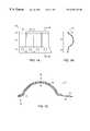
- FIG. 1Ais a schematic plan view of a portion of an EMI shield in accordance with one embodiment of the present invention
- FIG. 1Bis a schematic sectional view of the EMI shield depicted in FIG. 1A taken along line 1 B— 1 B;
- FIG. 1Cis an enlarged view of FIG. 1B rotated counterclockwise ninety degrees and including the metallized fabric.
- FIG. 2is a schematic sectional view of an EMI shield disposed in a gap in accordance with a another embodiment of the present invention
- FIG. 3is a schematic sectional view of an EMI shield in an uninstalled state in accordance with yet another embodiment of the present invention.
- FIG. 4is a schematic block diagram representation of a method of manufacture of an EMI shield by extrusion in accordance with one embodiment of the present invention.
- FIGS. 1A and 1Bare schematic plan and sectional views, respectively, of a metallized fabric clad polymer EMI shield 10 in accordance with one embodiment of the present invention.
- the shield 10is formed from an electrically nonconductive solid material to produce a substantially planar base 12 and a generally arcuate profile 14 having an offset tip 16 .
- the base 12is configured with a series of apertures 18 so that the base 12 can be secured to a first body (not depicted) by a plurality of nuts and bolts, self-tapping machine screws, rivets, or other mechanical fasteners.
- an enlarged sectional view of the EMI shield 10is depicted, including an electrically conductive layer of metallized fabric 20 disposed on the profile 14 .
- the relative thicknesses of the fabric 20 and the profile 14 in this and other embodimentsare for illustrative purposes only. In some embodiments, as will be discussed in greater detail hereinbelow, the thickness of the fabric 20 is typically substantially less than that of the profile 14 .
- the metallized fabric 20is bonded to the profile 14 with the fabric portion proximate the profile 14 and the metallic portion remote therefrom. The fabric 20 extends from the base 12 proximate the aperture 18 along the profile 14 and wraps around the offset tip 16 .
- the fabricprovides an electrically conductive path therebetween. Since the EMI shield 10 is secured to the first body solely at the base 12 in a bridge configuration, the tip 16 is free to slide across the first body as the profile 14 is compressed by the second body. By offsetting the tip 16 slightly, the tip 16 slides readily over imperfections in the surface of the first body. Accordingly, the profile 14 elastically deforms during compressive loading, such as when the door is closed, instead of being jammed and crushed.
- the plane of the base 12is offset from an end of the tip 16 so that when the EMI shield 10 is secured to the first body, a predetermined elastic deformation of the profile 14 results.
- This preloading of the EMI shield 10ensures that the tip 16 remains in intimate contact with the first body, thereby providing a positive electrical ground path.
- the fabric 20may extend along the base 12 covering the aperture 18 so that a redundant electrical ground path exists when a fastener such as an aluminum rivet passes through the fabric and aperture, securing the EMI shield 10 to the first body.
- the fabricmay extend further, wrapping around the base 12 so that the fabric 20 is captured between the base 12 and the first body thereby providing a more positive electrical ground path.
- the fabric 20may stop short of the tip 16 or need not wrap around the tip 16 , if desired.
- the profile 14 of the EMI shield 10may be divided at regular intervals into a plurality of independently flexible fingers 22 , each extending from the common base 12 .
- the EMI shield 10can provide effective shielding in a gap which varies in width along its length.
- Reliefs 24may be provided at the corners of the fingers 22 to blunt the fingers 22 and minimize catching of the tips 16 on surface imperfections in the first body.
- an EMI shield 100may have a substantially planar profile 114 attached to a substantially planar base 112 by a hinge 26 in a cantilevered configuration so that the EMI shield 100 resembles a recumbent “W” as depicted in FIG. 2.
- a metallized fabric 120envelops the entire exterior surface of the EMI shield 100 and wraps around respective tips of both the base 112 and profile 114 .
- the base 112may be attached to a first body 28 by a thin layer of adhesive 32 along a portion thereof to retain the EMI shield 100 in a predetermined position.
- the adhesive 32may be electrically conductive.
- the hinge 26elastically deforms to keep the profile 114 in contact therewith.
- the V-shaped configuration of the hinge 26is designed to accommodate a relatively large range of motion between the first and second bodies 28 , 30 while maintaining contact for electrical ground and shielding purposes; however, any of a variety of hinge configurations may be used. While the fabric 120 is depicted as being bonded to the entire exterior surface of the EMI shield 100 , for ease of manufacture the fabric 120 need not be bonded to the hinge 26 . A sufficient amount of fabric 120 should be provided in the area of the hinge 26 , however, so as not to restrict the full range of compression of the EMI shield 100 .
- the EMI shield 200includes a substantially planar profile 214 which forms an acute angle with a substantially planar base 212 in a cantilevered configuration so that the EMI shield 200 resembles a recumbent “U.”
- the base 212includes a return 34 which forms a throat 36 to permit mounting the EMI shield 200 on a planar flange of the first body.
- the returnincludes barbing 38 directed into the throat 36 to stabilize the EMI shield 200 once installed on the flange.
- the return 34could alternatively be configured for insertion into a slot in the first body. Barbing 38 extending in opposing directions from both sides of the return may be used to stabilize the EMI shield 200 in such a configuration.
- the profile 214is attached to the base 212 by a hinge 126 , but instead of being manufactured from the material used to make the base 212 and the profile 214 , the hinge 126 may be manufactured of a more flexible material resistant to fatigue failure to extend the life of the EMI shield 200 .
- a metallized fabric 220envelops the entire exterior surface of the EMI shield 200 , wrapping around the tip of profile 214 and extending into the throat 36 to provide a electrical ground path between the first and second bodies. While the fabric 220 is depicted as being bonded to the entire exterior surface of the EMI shield 200 , the fabric 220 need not be bonded to the hinge 126 . A sufficient amount of fabric 220 should be provided in the area of the hinge 126 , however, so as not to restrict the full range of compression of the EMI shield 200 .
- a cost effective method of manufacture of the various EMI shieldsis by continuous extrusion of one or more selected polymers using a screw extruder 40 having a die 42 with the desired shape of the cross-section of the shield 10 as depicted schematically in FIG. 4 .
- the shield 10may be manufactured from high temperature rated PVC for flame retardancy, although any electrically nonconductive material with a suitable modulus of elasticity may be employed. Flame retardancy is desirable, however, since such EMI shields can be approved for installation in safety certified electronic equipment enclosures.
- a compatible materialsuch as polyester can be coextruded with the profile and base to form the hinge.
- a suitable polyester hinge materialis HytrelTM, available from DuPont located in Wilmington, Del. Techniques of coextrusion are well known to those skilled in the art of polymer processing.
- an electrically conductive layeris disposed on the profile 14 and any other portion of the EMI shield 10 desired.
- One methodemploys a metallized fabric 20 in tape form of suitable width backed with a thermally activated glue.
- the gluemay cover substantially the entire backing or solely portions thereof such as along the edges.
- in-line crosshead extrusionas the polymer is being extruded through the die 42 , the hot extrusion passes through a second die 44 in which the metallized fabric tape 20 is mated thereto. The thermal energy in the extrusion and the second die 44 activates the glue, bonding the metallized fabric 20 to the profile 14 .
- the metallized fabric 20can be disposed on the extrusion in a separate operation, such as by passing the formed polymer and metallized fabric tape 20 through a heated die after the polymer has been cut to a desired length.
- metallized fabricsinclude articles having one or more metal coatings disposed on woven, nonwoven, or open mesh carrier backings and equivalents thereof. See, for example, U.S. Pat. No. 4,900,618 issued to O'Connor et al., U.S. Pat. No. 4,901,072 issued to Morgan et al.; U.S. Pat. No. 5,075,037 issued to Morgan et al., and U.S. Pat. No. 5,393,928 issued to Cribb et al., the disclosures of which are herein incorporated by reference.
- Metallized fabricsare commercially available in a variety of metal and fabric carrier backing combinations.
- pure copper on a nylon carriernickel-copper alloy on a nylon carrier, and pure nickel on a polyester mesh carrier are available under the registered trademark Flectron® from Advanced Performance Materials located in St. Louis, Mo.
- An aluminum foil on a polyester mesh carrieris available from Neptco, located in Pawtucket, R.I.
- Other suitable metalsinclude silver and tin.
- the choice of metalis guided, in part, by installation conditions of the EMI shield. For example, a particular metal might be chosen due to the composition of abutting body metal in the enclosure to avoid galvanic corrosion of the EMI shield which could increase electrical resistance and deteriorate electrical grounding performance.
- Metallized tapesare desirable both for ease of application as well as durability. Deposition of a metal layer directly on the polymer profile would wear away relatively quickly due to friction when compared to the metallized fabrics.
- the EMI shieldmay pass through rotary drilling, stamping, or piercing tools to divide the profile into independently flexible fingers or create apertures in the base for mounting the shield.
- the EMI shieldcan be cut to the desired length before or after these finishing operations.
- the metallized fabriccan be first bonded to either flat or preformed polymer sheet stock. Then, the sheet stock can be thermoformed to a final predetermined configuration by as known by those skilled in the art. Thermoforming can be accomplished on discrete pieces of sheet stock in a heated die or continuously by passing the sheet stock through heated rollers to produce the desired configuration. Additional manufacturing steps such as generating the mounting apertures or dividing the profile into fingers can be accomplished prior to, during, or after thermoforming, as desired.
- the electrical conductivity and the resultant EMI shielding capability of the EMI shield according to this inventionis improved over conventional copper beryllium finger strips.
- the polymer portion of the shieldis less brittle than all metal copper beryllium finger strips, resulting in reduced handling and installation damage to the EMI shield, improved safety, and extended service life.
- the thickness of an EMI shield profile according to the inventionmay be between about 0.13 mm (0.005 inches) or less and about 1.5 mm (0.060 inches) or more. In a preferred embodiment, the thickness of the EMI shield profile may be between about 0.25 mm (0.010 inches) or less and about 1.0 mm (0.04 inches) or more.
- the metallized fabricmay have a thickness between about 0.1 mm (0.004 inches) or less and about 0.5 mm (0.02 inches) or more.
Landscapes
- Engineering & Computer Science (AREA)
- Microelectronics & Electronic Packaging (AREA)
- Shielding Devices Or Components To Electric Or Magnetic Fields (AREA)
Abstract
Description
Claims (7)
Priority Applications (6)
| Application Number | Priority Date | Filing Date | Title |
|---|---|---|---|
| US08/962,417US6294729B1 (en) | 1997-10-31 | 1997-10-31 | Clad polymer EMI shield |
| AU12070/99AAU1207099A (en) | 1997-10-31 | 1998-10-30 | Clad polymer emi shield |
| PCT/US1998/023058WO1999023863A1 (en) | 1997-10-31 | 1998-10-30 | Clad polymer emi shield |
| US09/530,406US6534706B1 (en) | 1997-10-31 | 1998-10-30 | EMI shield having flexible fingers with nonlinear slits |
| US09/921,546US20020050373A1 (en) | 1997-10-31 | 2001-08-03 | Clad polymer EMI shield |
| US10/264,057US20030051891A1 (en) | 1997-10-31 | 2002-10-03 | Methods of manufacturing EMI shields |
Applications Claiming Priority (1)
| Application Number | Priority Date | Filing Date | Title |
|---|---|---|---|
| US08/962,417US6294729B1 (en) | 1997-10-31 | 1997-10-31 | Clad polymer EMI shield |
Related Child Applications (3)
| Application Number | Title | Priority Date | Filing Date |
|---|---|---|---|
| US09/530,406ContinuationUS6534706B1 (en) | 1997-10-31 | 1998-10-30 | EMI shield having flexible fingers with nonlinear slits |
| PCT/US1998/023058ContinuationWO1999023863A1 (en) | 1997-10-31 | 1998-10-30 | Clad polymer emi shield |
| US09/921,546DivisionUS20020050373A1 (en) | 1997-10-31 | 2001-08-03 | Clad polymer EMI shield |
Publications (2)
| Publication Number | Publication Date |
|---|---|
| US20010022230A1 US20010022230A1 (en) | 2001-09-20 |
| US6294729B1true US6294729B1 (en) | 2001-09-25 |
Family
ID=25505835
Family Applications (4)
| Application Number | Title | Priority Date | Filing Date |
|---|---|---|---|
| US08/962,417Expired - Fee RelatedUS6294729B1 (en) | 1997-10-31 | 1997-10-31 | Clad polymer EMI shield |
| US09/530,406Expired - LifetimeUS6534706B1 (en) | 1997-10-31 | 1998-10-30 | EMI shield having flexible fingers with nonlinear slits |
| US09/921,546AbandonedUS20020050373A1 (en) | 1997-10-31 | 2001-08-03 | Clad polymer EMI shield |
| US10/264,057AbandonedUS20030051891A1 (en) | 1997-10-31 | 2002-10-03 | Methods of manufacturing EMI shields |
Family Applications After (3)
| Application Number | Title | Priority Date | Filing Date |
|---|---|---|---|
| US09/530,406Expired - LifetimeUS6534706B1 (en) | 1997-10-31 | 1998-10-30 | EMI shield having flexible fingers with nonlinear slits |
| US09/921,546AbandonedUS20020050373A1 (en) | 1997-10-31 | 2001-08-03 | Clad polymer EMI shield |
| US10/264,057AbandonedUS20030051891A1 (en) | 1997-10-31 | 2002-10-03 | Methods of manufacturing EMI shields |
Country Status (3)
| Country | Link |
|---|---|
| US (4) | US6294729B1 (en) |
| AU (1) | AU1207099A (en) |
| WO (1) | WO1999023863A1 (en) |
Cited By (26)
| Publication number | Priority date | Publication date | Assignee | Title |
|---|---|---|---|---|
| US20020038684A1 (en)* | 1999-02-18 | 2002-04-04 | Andersen Corporation | Hinged thermoplastic-fabric reinforced structural member, profile and methods therefore |
| US6538197B1 (en)* | 2001-11-05 | 2003-03-25 | Kitigawa Industries Co., Ltd. | Conductive member |
| US6717047B2 (en)* | 2001-08-27 | 2004-04-06 | Hewlett-Packard Development Company, L.P. | EMI enclosure having a flexible cable shield |
| US6943288B1 (en) | 2004-06-04 | 2005-09-13 | Schlegel Systems, Inc. | EMI foil laminate gasket |
| USD519931S1 (en) | 2005-02-11 | 2006-05-02 | Phil Van Haaster | EMI/RFI shielding strip |
| US20060103080A1 (en)* | 2004-11-12 | 2006-05-18 | International Business Machines Corporation | Transferable cammed gasket |
| US7078614B1 (en) | 2005-02-11 | 2006-07-18 | Laird Technologies, Inc. | Shielding strips |
| US7084344B1 (en)* | 2006-01-05 | 2006-08-01 | International Business Machines Corporation | V-seal EMC gasket assembly for precise placement, conduction and retention without adhesives |
| US20060180347A1 (en)* | 2005-02-11 | 2006-08-17 | Phil Van Haaster | Shielding strips |
| USD541752S1 (en) | 2005-02-11 | 2007-05-01 | Laird Technologies, Inc. | Slot pattern for EMI/RFI shield |
| US20080047745A1 (en)* | 2006-08-28 | 2008-02-28 | David Christopher Smeltz | Flexible clip-on shielding and/or grounding strips |
| US20090067149A1 (en)* | 2007-09-07 | 2009-03-12 | Robert Bogursky | Electronic shielding apparatus and methods |
| US7557290B2 (en) | 2002-05-17 | 2009-07-07 | Schripsema Jason E | Photovoltaic module with adjustable heat sink and method of fabrication |
| US20100157566A1 (en)* | 2008-12-19 | 2010-06-24 | Robert Bogursky | Electronic shield assembly and methods |
| US20100240228A1 (en)* | 2009-03-06 | 2010-09-23 | Saint-Gobain Performance Plastics Corporation | Linear motion electrical connector assembly |
| US20110079962A1 (en)* | 2009-10-02 | 2011-04-07 | Saint-Gobain Performance Plastics Corporation | Modular polymeric emi/rfi seal |
| US20110126463A1 (en)* | 2009-05-19 | 2011-06-02 | Ets-Lindgren | Multiseal door, method for sealing an enclosure |
| US20140268583A1 (en)* | 2013-03-15 | 2014-09-18 | Autoliv Asp Inc. | Electrical Gasket and Electronic Module Having Electrical Gasket |
| US8925251B1 (en)* | 2013-12-10 | 2015-01-06 | Stephen Vincent Rust | Constant force spring perimeter seal for an electromagnetic shielded door |
| US20150055304A1 (en)* | 2013-08-26 | 2015-02-26 | Wistron Corporation | Electronic device |
| US20150360795A1 (en)* | 2014-06-17 | 2015-12-17 | The Boeing Company | Fire Seal for an Aircraft |
| US11147195B2 (en) | 2018-06-02 | 2021-10-12 | Merakai, LLC | Faraday enclosure apparatus and method of manufacturing same |
| USD998827S1 (en)* | 2017-10-06 | 2023-09-12 | Laird Technologies, Inc. | Material having edge shape |
| USD999405S1 (en)* | 2017-10-06 | 2023-09-19 | Laird Technologies, Inc. | Material having edging |
| US12040306B2 (en) | 2016-07-11 | 2024-07-16 | Laird Technologies, Inc. | Systems of applying materials to components |
| US12331586B2 (en)* | 2022-08-03 | 2025-06-17 | Aadg, Inc. | Door assembly and components for providing electromagnetic compatibility (EMC) shielding |
Families Citing this family (35)
| Publication number | Priority date | Publication date | Assignee | Title |
|---|---|---|---|---|
| JP3094311U (en)* | 2001-12-28 | 2003-06-13 | 榮益科技有限公司 | Thin leaf spring used for connecting circuit boards |
| TW582566U (en)* | 2002-04-17 | 2004-04-01 | Quanta Comp Inc | Flipping plate for anti-interfering and expanding slot using the flipping plate |
| US20030227759A1 (en)* | 2002-06-10 | 2003-12-11 | Haworth Stephen Paul | Electromagnetic interference gasket |
| GB2389710B (en)* | 2002-06-10 | 2006-02-08 | Sun Microsystems Inc | Electronics module |
| US6744641B2 (en) | 2002-06-10 | 2004-06-01 | Sun Microsystems, Inc. | Electromagnetic interference gasket |
| US6774301B1 (en)* | 2002-11-05 | 2004-08-10 | Cisco Technology, Inc. | Electromagnetic interference gasket |
| US7088009B2 (en)* | 2003-08-20 | 2006-08-08 | Freescale Semiconductor, Inc. | Wirebonded assemblage method and apparatus |
| US7170013B2 (en)* | 2004-04-08 | 2007-01-30 | Hewlett-Packard Development Company, L.P. | Spring fingers with end extensions |
| US7507242B2 (en) | 2004-06-02 | 2009-03-24 | Facet Solutions | Surgical measurement and resection framework |
| DE502005002990D1 (en)* | 2005-03-11 | 2008-04-10 | Schroff Gmbh | RF sealing strip |
| DE102006038221B4 (en)* | 2006-08-03 | 2009-03-26 | Siemens Ag | Device for electrical shielding of a high voltage feedthrough |
| US7729130B1 (en)* | 2007-01-02 | 2010-06-01 | Fourte Design & Development LLC | Transceiver module with collapsible fingers that form a sealed EMI shield |
| USD555595S1 (en)* | 2007-01-03 | 2007-11-20 | Ebara Corporation | Electrical contact for use in a plating apparatus |
| USD556692S1 (en)* | 2007-01-03 | 2007-12-04 | Ebara Corporation | Electrical contact for use in a plating apparatus |
| US7527506B2 (en)* | 2007-08-31 | 2009-05-05 | Laird Technologies, Inc. | EMI shielding/electrical grounding members |
| US20090110471A1 (en)* | 2007-10-31 | 2009-04-30 | Montminy Jeffrey E | system of fasteners for attaching panels onto modules that are to be installed on an airplane ground support equipment cart |
| US7763810B2 (en)* | 2007-11-07 | 2010-07-27 | Laird Technologies, Inc. | Fabric-over-foam EMI gaskets having transverse slits and related methods |
| TWI331084B (en)* | 2008-05-12 | 2010-10-01 | Asustek Comp Inc | In-mold decoration device and manufacturing method thereof |
| US7869224B1 (en)* | 2009-09-18 | 2011-01-11 | All Best Precision Technology Co., Ltd. | Housing structure for pluggable transceiver module |
| USD651178S1 (en) | 2010-02-26 | 2011-12-27 | Ebara Corporation | Electrical contact for use in a plating apparatus |
| US8157593B1 (en) | 2010-12-16 | 2012-04-17 | Hewlett-Packard Development Company, L.P. | Method of shielding a connector module from electromagnetic interference with elongate members of conductive material and related apparatus |
| US20130048367A1 (en)* | 2011-08-22 | 2013-02-28 | Zlatan Ljubijankic | Emi shielding members for connector cage |
| EP2487696B1 (en)* | 2012-03-28 | 2014-03-12 | ABB Technology AG | Shielding electrode and oil-fired boiler |
| CN104509231A (en) | 2012-07-28 | 2015-04-08 | 莱尔德技术股份有限公司 | Metallized film-over-foam contacts |
| US8952258B2 (en)* | 2012-09-21 | 2015-02-10 | International Business Machines Corporation | Implementing graphene interconnect for high conductivity applications |
| US9226433B2 (en) | 2013-03-15 | 2015-12-29 | Laird Technologies, Inc. | Selectively conductive EMI gaskets |
| US8884168B2 (en) | 2013-03-15 | 2014-11-11 | Laird Technologies, Inc. | Selectively conductive EMI gaskets |
| WO2016111512A1 (en) | 2015-01-09 | 2016-07-14 | Samsung Electronics Co., Ltd. | Semiconductor package and method of manufacturing the same |
| USD797674S1 (en) | 2015-01-20 | 2017-09-19 | Ebara Corporation | Electrical contact |
| DE102017101414A1 (en)* | 2017-01-25 | 2018-07-26 | Sma Solar Technology Ag | EMI SHIELDED SEAL AND ELECTRICAL OR ELECTRONIC DEVICE WITH ONE SEAL |
| DE102017108607A1 (en)* | 2017-04-21 | 2018-10-25 | Bimed Teknik Aletler Sanayi Ve Ticaret A.S. | Cable bushing system, module and assembly process |
| EP3698493B1 (en)* | 2017-10-16 | 2022-08-10 | Promptlink Communications, Inc. | Enclosure for testing electronic devices |
| JP7322027B2 (en)* | 2018-07-31 | 2023-08-07 | ソニーセミコンダクタソリューションズ株式会社 | In-vehicle camera |
| US11945375B2 (en) | 2018-07-31 | 2024-04-02 | Sony Semiconductor Solutions Corporation | Onboard camera holding method, onboard camera, bracket |
| US12016167B2 (en) | 2022-04-11 | 2024-06-18 | Dell Products L.P. | Tear-drop shaped HDD carrier EMI finger |
Citations (38)
| Publication number | Priority date | Publication date | Assignee | Title |
|---|---|---|---|---|
| US2756468A (en) | 1952-11-04 | 1956-07-31 | Bright Thomas John Robert | Sealing strips |
| US3277230A (en) | 1965-03-17 | 1966-10-04 | Instr Specialties Co Inc | Shielding gaskets with fastening means |
| US3446906A (en) | 1967-05-17 | 1969-05-27 | Tektronix Inc | Resilient conductive coated foam member and electromagnetic shield employing same |
| US3502784A (en) | 1968-09-11 | 1970-03-24 | Scanbe Mfg Corp | Gasket |
| US3504095A (en) | 1968-01-30 | 1970-03-31 | Instr Specialties Co Inc | Shielding gaskets |
| US3512946A (en) | 1967-04-17 | 1970-05-19 | Lash Mfg Inc | Composite material for shielding electrical and magnetic energy |
| US3700368A (en) | 1969-01-22 | 1972-10-24 | Howard E Wells | Continuous molding apparatus |
| US3889043A (en) | 1972-06-09 | 1975-06-10 | Ducros Emile Paul J J | Earthing joint for shielding chambers electrically and electromagnetically |
| US4399317A (en) | 1981-09-18 | 1983-08-16 | Keene Corporation | Sealing apparatus for radio frequency shielding enclosure |
| US4434541A (en) | 1980-12-22 | 1984-03-06 | Chomerics, Inc. | Electromagnetic shielding |
| US4572921A (en) | 1984-07-30 | 1986-02-25 | Instrument Specialties Co., Inc. | Electromagnetic shielding device |
| US4857668A (en) | 1988-04-15 | 1989-08-15 | Schlegel Corporation | Multi-function gasket |
| US4864076A (en) | 1988-10-24 | 1989-09-05 | Instrument Specialties Co., Inc. | Electromagnetic shielding and environmental sealing device |
| US4900618A (en) | 1986-11-07 | 1990-02-13 | Monsanto Company | Oxidation-resistant metal coatings |
| US4910072A (en) | 1986-11-07 | 1990-03-20 | Monsanto Company | Selective catalytic activation of polymeric films |
| US5043528A (en)* | 1989-03-30 | 1991-08-27 | Richard Mohr | Device for providing electrical continuity between electrically conductive surfaces |
| US5070216A (en) | 1990-04-27 | 1991-12-03 | Chomerics, Inc. | Emi shielding gasket |
| US5075037A (en) | 1986-11-07 | 1991-12-24 | Monsanto Company | Selective catalytic activation of polymeric films |
| US5082734A (en) | 1989-12-21 | 1992-01-21 | Monsanto Company | Catalytic, water-soluble polymeric films for metal coatings |
| US5120903A (en)* | 1990-08-06 | 1992-06-09 | Kitagawa Industries Co., Ltd. | Electromagnetic shielding member |
| US5142101A (en)* | 1990-11-29 | 1992-08-25 | Kitagawa Industries Co., Ltd. | Electromagnetic-shielding gasket |
| US5275861A (en) | 1989-12-21 | 1994-01-04 | Monsanto Company | Radiation shielding fabric |
| US5348574A (en) | 1993-07-02 | 1994-09-20 | Monsanto Company | Metal-coated polyimide |
| US5393928A (en) | 1993-02-19 | 1995-02-28 | Monsanto Company | Shielded cable assemblies |
| US5458955A (en) | 1993-10-21 | 1995-10-17 | Monsanto Company | Metal/polymer laminates having an anionomeric polymer film layer |
| US5467254A (en) | 1993-11-04 | 1995-11-14 | Synoptics Communications, Inc. | Supportive guide for circuit-card grounding including tracks having staggered protrusions at the proximal end of the tracks |
| US5483423A (en) | 1993-11-16 | 1996-01-09 | Digital Equipment Corporation | EMI shielding for components |
| US5511798A (en)* | 1993-07-22 | 1996-04-30 | Nec Corporation | EMI gasket |
| US5522602A (en) | 1992-11-25 | 1996-06-04 | Amesbury Group Inc. | EMI-shielding gasket |
| US5569877A (en)* | 1994-04-14 | 1996-10-29 | Kitagawa Industries Co., Ltd. | Sewn material and method for shielding against electromagnetic waves |
| US5600544A (en) | 1992-10-29 | 1997-02-04 | Siemens Aktiengesellschaft | Shielding device for a backplane plug connector |
| US5646369A (en) | 1995-04-03 | 1997-07-08 | Schlegel Corporation | Segmented shielding structure for connector panels |
| US5656795A (en) | 1995-04-03 | 1997-08-12 | Schlegel Corporation | Segmented shielding structure for connector panels |
| US5672844A (en) | 1993-12-10 | 1997-09-30 | Ericsson Inc. | Apparatus for the suppression of electromagnetic interference in an electronic system |
| US5679923A (en) | 1995-02-17 | 1997-10-21 | Ast Research, Inc. | Shielding panel |
| US5703762A (en) | 1994-06-27 | 1997-12-30 | Zell; Karl | Arrangement for connecting wiring backplanes and module circuit boards |
| US5712449A (en) | 1995-05-24 | 1998-01-27 | Schlegel Corporation | Wide area emi gasket with conductors traversing core |
| JPH10224073A (en) | 1997-02-13 | 1998-08-21 | Nitto Kogyo Co Ltd | Electromagnetic shielding packing |
Family Cites Families (1)
| Publication number | Priority date | Publication date | Assignee | Title |
|---|---|---|---|---|
| US5581048A (en)* | 1984-11-28 | 1996-12-03 | Hughes Missile Systems Company | Corrosion resistant electromagnetic shielding gasket |
- 1997
- 1997-10-31USUS08/962,417patent/US6294729B1/ennot_activeExpired - Fee Related
- 1998
- 1998-10-30AUAU12070/99Apatent/AU1207099A/ennot_activeAbandoned
- 1998-10-30WOPCT/US1998/023058patent/WO1999023863A1/enactiveApplication Filing
- 1998-10-30USUS09/530,406patent/US6534706B1/ennot_activeExpired - Lifetime
- 2001
- 2001-08-03USUS09/921,546patent/US20020050373A1/ennot_activeAbandoned
- 2002
- 2002-10-03USUS10/264,057patent/US20030051891A1/ennot_activeAbandoned
Patent Citations (38)
| Publication number | Priority date | Publication date | Assignee | Title |
|---|---|---|---|---|
| US2756468A (en) | 1952-11-04 | 1956-07-31 | Bright Thomas John Robert | Sealing strips |
| US3277230A (en) | 1965-03-17 | 1966-10-04 | Instr Specialties Co Inc | Shielding gaskets with fastening means |
| US3512946A (en) | 1967-04-17 | 1970-05-19 | Lash Mfg Inc | Composite material for shielding electrical and magnetic energy |
| US3446906A (en) | 1967-05-17 | 1969-05-27 | Tektronix Inc | Resilient conductive coated foam member and electromagnetic shield employing same |
| US3504095A (en) | 1968-01-30 | 1970-03-31 | Instr Specialties Co Inc | Shielding gaskets |
| US3502784A (en) | 1968-09-11 | 1970-03-24 | Scanbe Mfg Corp | Gasket |
| US3700368A (en) | 1969-01-22 | 1972-10-24 | Howard E Wells | Continuous molding apparatus |
| US3889043A (en) | 1972-06-09 | 1975-06-10 | Ducros Emile Paul J J | Earthing joint for shielding chambers electrically and electromagnetically |
| US4434541A (en) | 1980-12-22 | 1984-03-06 | Chomerics, Inc. | Electromagnetic shielding |
| US4399317A (en) | 1981-09-18 | 1983-08-16 | Keene Corporation | Sealing apparatus for radio frequency shielding enclosure |
| US4572921A (en) | 1984-07-30 | 1986-02-25 | Instrument Specialties Co., Inc. | Electromagnetic shielding device |
| US4900618A (en) | 1986-11-07 | 1990-02-13 | Monsanto Company | Oxidation-resistant metal coatings |
| US4910072A (en) | 1986-11-07 | 1990-03-20 | Monsanto Company | Selective catalytic activation of polymeric films |
| US5075037A (en) | 1986-11-07 | 1991-12-24 | Monsanto Company | Selective catalytic activation of polymeric films |
| US4857668A (en) | 1988-04-15 | 1989-08-15 | Schlegel Corporation | Multi-function gasket |
| US4864076A (en) | 1988-10-24 | 1989-09-05 | Instrument Specialties Co., Inc. | Electromagnetic shielding and environmental sealing device |
| US5043528A (en)* | 1989-03-30 | 1991-08-27 | Richard Mohr | Device for providing electrical continuity between electrically conductive surfaces |
| US5082734A (en) | 1989-12-21 | 1992-01-21 | Monsanto Company | Catalytic, water-soluble polymeric films for metal coatings |
| US5275861A (en) | 1989-12-21 | 1994-01-04 | Monsanto Company | Radiation shielding fabric |
| US5070216A (en) | 1990-04-27 | 1991-12-03 | Chomerics, Inc. | Emi shielding gasket |
| US5120903A (en)* | 1990-08-06 | 1992-06-09 | Kitagawa Industries Co., Ltd. | Electromagnetic shielding member |
| US5142101A (en)* | 1990-11-29 | 1992-08-25 | Kitagawa Industries Co., Ltd. | Electromagnetic-shielding gasket |
| US5600544A (en) | 1992-10-29 | 1997-02-04 | Siemens Aktiengesellschaft | Shielding device for a backplane plug connector |
| US5522602A (en) | 1992-11-25 | 1996-06-04 | Amesbury Group Inc. | EMI-shielding gasket |
| US5393928A (en) | 1993-02-19 | 1995-02-28 | Monsanto Company | Shielded cable assemblies |
| US5348574A (en) | 1993-07-02 | 1994-09-20 | Monsanto Company | Metal-coated polyimide |
| US5511798A (en)* | 1993-07-22 | 1996-04-30 | Nec Corporation | EMI gasket |
| US5458955A (en) | 1993-10-21 | 1995-10-17 | Monsanto Company | Metal/polymer laminates having an anionomeric polymer film layer |
| US5467254A (en) | 1993-11-04 | 1995-11-14 | Synoptics Communications, Inc. | Supportive guide for circuit-card grounding including tracks having staggered protrusions at the proximal end of the tracks |
| US5483423A (en) | 1993-11-16 | 1996-01-09 | Digital Equipment Corporation | EMI shielding for components |
| US5672844A (en) | 1993-12-10 | 1997-09-30 | Ericsson Inc. | Apparatus for the suppression of electromagnetic interference in an electronic system |
| US5569877A (en)* | 1994-04-14 | 1996-10-29 | Kitagawa Industries Co., Ltd. | Sewn material and method for shielding against electromagnetic waves |
| US5703762A (en) | 1994-06-27 | 1997-12-30 | Zell; Karl | Arrangement for connecting wiring backplanes and module circuit boards |
| US5679923A (en) | 1995-02-17 | 1997-10-21 | Ast Research, Inc. | Shielding panel |
| US5656795A (en) | 1995-04-03 | 1997-08-12 | Schlegel Corporation | Segmented shielding structure for connector panels |
| US5646369A (en) | 1995-04-03 | 1997-07-08 | Schlegel Corporation | Segmented shielding structure for connector panels |
| US5712449A (en) | 1995-05-24 | 1998-01-27 | Schlegel Corporation | Wide area emi gasket with conductors traversing core |
| JPH10224073A (en) | 1997-02-13 | 1998-08-21 | Nitto Kogyo Co Ltd | Electromagnetic shielding packing |
Non-Patent Citations (3)
| Title |
|---|
| Electromagnetic Shielding Products and Thermally Conductive Insulators; Warth catalog, front and back covers and pp. 34-79; Copyright Warth International Ltd. (1995). |
| Foam Tite EMI Shielding Gaskets; Advanced Performance Materials spec. sheet, double sided, (7/97). |
| Foam-Tite 100 EMI Shielding Gasket; Advanced Performance Materials spec.sheet, double sided, (5/97). |
Cited By (34)
| Publication number | Priority date | Publication date | Assignee | Title |
|---|---|---|---|---|
| US20020038684A1 (en)* | 1999-02-18 | 2002-04-04 | Andersen Corporation | Hinged thermoplastic-fabric reinforced structural member, profile and methods therefore |
| US6717047B2 (en)* | 2001-08-27 | 2004-04-06 | Hewlett-Packard Development Company, L.P. | EMI enclosure having a flexible cable shield |
| US6538197B1 (en)* | 2001-11-05 | 2003-03-25 | Kitigawa Industries Co., Ltd. | Conductive member |
| US7557290B2 (en) | 2002-05-17 | 2009-07-07 | Schripsema Jason E | Photovoltaic module with adjustable heat sink and method of fabrication |
| US6943288B1 (en) | 2004-06-04 | 2005-09-13 | Schlegel Systems, Inc. | EMI foil laminate gasket |
| US7086653B2 (en)* | 2004-11-12 | 2006-08-08 | International Business Machines Corporation | Transferable cammed gasket |
| US20060103080A1 (en)* | 2004-11-12 | 2006-05-18 | International Business Machines Corporation | Transferable cammed gasket |
| USD519931S1 (en) | 2005-02-11 | 2006-05-02 | Phil Van Haaster | EMI/RFI shielding strip |
| US20060180347A1 (en)* | 2005-02-11 | 2006-08-17 | Phil Van Haaster | Shielding strips |
| US7112740B2 (en) | 2005-02-11 | 2006-09-26 | Laird Technologies, Inc. | Shielding strips |
| USD541752S1 (en) | 2005-02-11 | 2007-05-01 | Laird Technologies, Inc. | Slot pattern for EMI/RFI shield |
| US7078614B1 (en) | 2005-02-11 | 2006-07-18 | Laird Technologies, Inc. | Shielding strips |
| US7084344B1 (en)* | 2006-01-05 | 2006-08-01 | International Business Machines Corporation | V-seal EMC gasket assembly for precise placement, conduction and retention without adhesives |
| US20080047745A1 (en)* | 2006-08-28 | 2008-02-28 | David Christopher Smeltz | Flexible clip-on shielding and/or grounding strips |
| US20090067149A1 (en)* | 2007-09-07 | 2009-03-12 | Robert Bogursky | Electronic shielding apparatus and methods |
| US8031485B2 (en) | 2007-09-07 | 2011-10-04 | Autosplice, Inc. | Electronic shielding apparatus and methods |
| US20100157566A1 (en)* | 2008-12-19 | 2010-06-24 | Robert Bogursky | Electronic shield assembly and methods |
| US20100240228A1 (en)* | 2009-03-06 | 2010-09-23 | Saint-Gobain Performance Plastics Corporation | Linear motion electrical connector assembly |
| US8128416B2 (en) | 2009-03-06 | 2012-03-06 | Saint-Gobain Performance Plastics Corporation | Linear motion electrical connector assembly |
| US20110126463A1 (en)* | 2009-05-19 | 2011-06-02 | Ets-Lindgren | Multiseal door, method for sealing an enclosure |
| US8677688B2 (en)* | 2009-05-19 | 2014-03-25 | ETS-Lindgren Inc. | Multiseal door, method for sealing an enclosure |
| US20110079962A1 (en)* | 2009-10-02 | 2011-04-07 | Saint-Gobain Performance Plastics Corporation | Modular polymeric emi/rfi seal |
| US9332680B2 (en)* | 2013-03-15 | 2016-05-03 | Autoliv Asp, Inc. | Electrical gasket and electronic module having electrical gasket |
| US20140268583A1 (en)* | 2013-03-15 | 2014-09-18 | Autoliv Asp Inc. | Electrical Gasket and Electronic Module Having Electrical Gasket |
| US20150055304A1 (en)* | 2013-08-26 | 2015-02-26 | Wistron Corporation | Electronic device |
| US8925251B1 (en)* | 2013-12-10 | 2015-01-06 | Stephen Vincent Rust | Constant force spring perimeter seal for an electromagnetic shielded door |
| US20150360795A1 (en)* | 2014-06-17 | 2015-12-17 | The Boeing Company | Fire Seal for an Aircraft |
| US9643733B2 (en)* | 2014-06-17 | 2017-05-09 | The Boeing Company | Fire seal for an aircraft |
| US12040306B2 (en) | 2016-07-11 | 2024-07-16 | Laird Technologies, Inc. | Systems of applying materials to components |
| USD998827S1 (en)* | 2017-10-06 | 2023-09-12 | Laird Technologies, Inc. | Material having edge shape |
| USD999405S1 (en)* | 2017-10-06 | 2023-09-19 | Laird Technologies, Inc. | Material having edging |
| US11147195B2 (en) | 2018-06-02 | 2021-10-12 | Merakai, LLC | Faraday enclosure apparatus and method of manufacturing same |
| US11547029B2 (en) | 2018-06-02 | 2023-01-03 | Merakai, LLC | Faraday enclosure apparatus and method of manufacturing same |
| US12331586B2 (en)* | 2022-08-03 | 2025-06-17 | Aadg, Inc. | Door assembly and components for providing electromagnetic compatibility (EMC) shielding |
Also Published As
| Publication number | Publication date |
|---|---|
| US20030051891A1 (en) | 2003-03-20 |
| US20010022230A1 (en) | 2001-09-20 |
| AU1207099A (en) | 1999-05-24 |
| US6534706B1 (en) | 2003-03-18 |
| WO1999023863A1 (en) | 1999-05-14 |
| US20020050373A1 (en) | 2002-05-02 |
Similar Documents
| Publication | Publication Date | Title |
|---|---|---|
| US6294729B1 (en) | Clad polymer EMI shield | |
| US6477061B1 (en) | I/O port EMI shield | |
| US7763810B2 (en) | Fabric-over-foam EMI gaskets having transverse slits and related methods | |
| EP1799023B1 (en) | Methods and apparatus for EMI schielding | |
| EP1779713B1 (en) | Emi foil laminate gasket | |
| US5070216A (en) | Emi shielding gasket | |
| CA2308774C (en) | Tubular gasket for improved environmental sealing and emi shielding | |
| CA1309486C (en) | Multi-function gasket | |
| JP2003037386A (en) | Abrasion-resistant conductive film and gasket | |
| WO1996008946A1 (en) | Multi-layer emi/rfi gasket shield | |
| US6465731B1 (en) | Through conductive EMI shielding gasket | |
| US4786758A (en) | Door shield for shielded enclosure | |
| US7402761B2 (en) | Electric conductive gasket | |
| US20160262291A1 (en) | Gasket having two regions of foam densities | |
| US9226433B2 (en) | Selectively conductive EMI gaskets | |
| US20060081389A1 (en) | Aesthetically colored EMI shields | |
| EP1158846B1 (en) | Tubular gasket for improved environmental sealing and EMI shielding | |
| JP4747833B2 (en) | Sheet metal member coupling structure and automatic transaction apparatus | |
| US20060080825A1 (en) | Methods related to electromagnetic interference shielding | |
| JPH0240240B2 (en) |
Legal Events
| Date | Code | Title | Description |
|---|---|---|---|
| AS | Assignment | Owner name:AMESBURY GROUP, INC., MASSACHUSETTS Free format text:ASSIGNMENT OF ASSIGNORS INTEREST;ASSIGNOR:KAPLO, JOSEPH J.;REEL/FRAME:009029/0920 Effective date:19971218 | |
| AS | Assignment | Owner name:APM, INC., MISSOURI Free format text:ASSIGNMENT OF ASSIGNORS INTEREST;ASSIGNOR:AMESBURY GROUP, INC.;REEL/FRAME:014972/0681 Effective date:20031217 | |
| FEPP | Fee payment procedure | Free format text:PAYOR NUMBER ASSIGNED (ORIGINAL EVENT CODE: ASPN); ENTITY STATUS OF PATENT OWNER: LARGE ENTITY | |
| FPAY | Fee payment | Year of fee payment:4 | |
| AS | Assignment | Owner name:LAIRD TECHNOLOGIES, INC., MISSOURI Free format text:MERGER;ASSIGNOR:APM, INC.;REEL/FRAME:017325/0456 Effective date:20041216 | |
| FEPP | Fee payment procedure | Free format text:PAYOR NUMBER ASSIGNED (ORIGINAL EVENT CODE: ASPN); ENTITY STATUS OF PATENT OWNER: LARGE ENTITY Free format text:PAYER NUMBER DE-ASSIGNED (ORIGINAL EVENT CODE: RMPN); ENTITY STATUS OF PATENT OWNER: LARGE ENTITY | |
| FEPP | Fee payment procedure | Free format text:PAYOR NUMBER ASSIGNED (ORIGINAL EVENT CODE: ASPN); ENTITY STATUS OF PATENT OWNER: LARGE ENTITY Free format text:PAYER NUMBER DE-ASSIGNED (ORIGINAL EVENT CODE: RMPN); ENTITY STATUS OF PATENT OWNER: LARGE ENTITY | |
| FPAY | Fee payment | Year of fee payment:8 | |
| REMI | Maintenance fee reminder mailed | ||
| LAPS | Lapse for failure to pay maintenance fees | ||
| STCH | Information on status: patent discontinuation | Free format text:PATENT EXPIRED DUE TO NONPAYMENT OF MAINTENANCE FEES UNDER 37 CFR 1.362 | |
| FP | Lapsed due to failure to pay maintenance fee | Effective date:20130925 |