US6293955B1 - Percutaneous bypass graft and securing system - Google Patents
Percutaneous bypass graft and securing systemDownload PDFInfo
- Publication number
- US6293955B1 US6293955B1US09/415,776US41577699AUS6293955B1US 6293955 B1US6293955 B1US 6293955B1US 41577699 AUS41577699 AUS 41577699AUS 6293955 B1US6293955 B1US 6293955B1
- Authority
- US
- United States
- Prior art keywords
- graft
- collet
- vessel
- connector system
- dilator
- Prior art date
- Legal status (The legal status is an assumption and is not a legal conclusion. Google has not performed a legal analysis and makes no representation as to the accuracy of the status listed.)
- Expired - Fee Related
Links
- 210000000056organAnatomy0.000claimsabstractdescription14
- 210000004204blood vesselAnatomy0.000claimsabstractdescription4
- 239000012530fluidSubstances0.000claimsdescription17
- 239000000463materialSubstances0.000claimsdescription16
- 239000012528membraneSubstances0.000claimsdescription7
- 229910001000nickel titaniumInorganic materials0.000claimsdescription4
- 239000010935stainless steelSubstances0.000claimsdescription4
- 229910001220stainless steelInorganic materials0.000claimsdescription4
- 229920001187thermosetting polymerPolymers0.000claimsdescription3
- HZEWFHLRYVTOIW-UHFFFAOYSA-N[Ti].[Ni]Chemical compound[Ti].[Ni]HZEWFHLRYVTOIW-UHFFFAOYSA-N0.000claims2
- 239000013013elastic materialSubstances0.000claims2
- 230000000149penetrating effectEffects0.000claims1
- 230000007246mechanismEffects0.000abstractdescription19
- 230000003902lesionEffects0.000description19
- 230000000916dilatatory effectEffects0.000description13
- 238000000034methodMethods0.000description11
- 238000010438heat treatmentMethods0.000description6
- 238000003780insertionMethods0.000description5
- 230000037431insertionEffects0.000description5
- 230000033001locomotionEffects0.000description4
- 210000005166vasculatureAnatomy0.000description4
- 239000008280bloodSubstances0.000description3
- 210000004369bloodAnatomy0.000description3
- 230000008878couplingEffects0.000description3
- 238000010168coupling processMethods0.000description3
- 238000005859coupling reactionMethods0.000description3
- 230000004118muscle contractionEffects0.000description3
- 229920000642polymerPolymers0.000description3
- 230000008569processEffects0.000description3
- 206010046543Urinary incontinenceDiseases0.000description2
- 239000000853adhesiveSubstances0.000description2
- 230000001070adhesive effectEffects0.000description2
- 238000013459approachMethods0.000description2
- 230000008901benefitEffects0.000description2
- 230000000747cardiac effectEffects0.000description2
- 238000004891communicationMethods0.000description2
- 238000005520cutting processMethods0.000description2
- 238000007598dipping methodMethods0.000description2
- 229910052751metalInorganic materials0.000description2
- 239000002184metalSubstances0.000description2
- BASFCYQUMIYNBI-UHFFFAOYSA-NplatinumChemical compound[Pt]BASFCYQUMIYNBI-UHFFFAOYSA-N0.000description2
- 238000012800visualizationMethods0.000description2
- 238000004804windingMethods0.000description2
- JOYRKODLDBILNP-UHFFFAOYSA-NEthyl urethaneChemical compoundCCOC(N)=OJOYRKODLDBILNP-UHFFFAOYSA-N0.000description1
- 208000010496Heart ArrestDiseases0.000description1
- 206010061216InfarctionDiseases0.000description1
- 239000004677NylonSubstances0.000description1
- 239000004698PolyethyleneSubstances0.000description1
- 239000004642PolyimideSubstances0.000description1
- 208000025865UlcerDiseases0.000description1
- 238000002399angioplastyMethods0.000description1
- 210000000709aortaAnatomy0.000description1
- 230000002612cardiopulmonary effectEffects0.000description1
- 230000015556catabolic processEffects0.000description1
- 230000015271coagulationEffects0.000description1
- 238000005345coagulationMethods0.000description1
- 239000004020conductorSubstances0.000description1
- 238000010276constructionMethods0.000description1
- 239000002872contrast mediaSubstances0.000description1
- 238000007796conventional methodMethods0.000description1
- 230000007547defectEffects0.000description1
- 230000010339dilationEffects0.000description1
- 239000003814drugSubstances0.000description1
- 229940079593drugDrugs0.000description1
- 230000002500effect on skinEffects0.000description1
- 230000003511endothelial effectEffects0.000description1
- 239000006260foamSubstances0.000description1
- 230000002496gastric effectEffects0.000description1
- PCHJSUWPFVWCPO-UHFFFAOYSA-NgoldChemical compound[Au]PCHJSUWPFVWCPO-UHFFFAOYSA-N0.000description1
- 239000010931goldSubstances0.000description1
- 229910052737goldInorganic materials0.000description1
- 238000003384imaging methodMethods0.000description1
- 238000002513implantationMethods0.000description1
- 230000007574infarctionEffects0.000description1
- 208000000509infertilityDiseases0.000description1
- 230000036512infertilityEffects0.000description1
- 231100000535infertilityToxicity0.000description1
- 208000028867ischemiaDiseases0.000description1
- 238000004519manufacturing processMethods0.000description1
- 229920001778nylonPolymers0.000description1
- 229910052697platinumInorganic materials0.000description1
- HWLDNSXPUQTBOD-UHFFFAOYSA-Nplatinum-iridium alloyChemical compound[Ir].[Pt]HWLDNSXPUQTBOD-UHFFFAOYSA-N0.000description1
- -1polyethylenePolymers0.000description1
- 229920000573polyethylenePolymers0.000description1
- 229920001721polyimidePolymers0.000description1
- 229920001296polysiloxanePolymers0.000description1
- 239000004810polytetrafluoroethyleneSubstances0.000description1
- 229920001343polytetrafluoroethylenePolymers0.000description1
- 230000000750progressive effectEffects0.000description1
- 210000003752saphenous veinAnatomy0.000description1
- 238000009958sewingMethods0.000description1
- 229910000679solderInorganic materials0.000description1
- 239000007787solidSubstances0.000description1
- 238000001356surgical procedureMethods0.000description1
- 210000000115thoracic cavityAnatomy0.000description1
- 231100000397ulcerToxicity0.000description1
- 210000002700urineAnatomy0.000description1
- 208000019553vascular diseaseDiseases0.000description1
- 238000003466weldingMethods0.000description1
- 229910000859α-FeInorganic materials0.000description1
Images


Classifications
- A—HUMAN NECESSITIES
- A61—MEDICAL OR VETERINARY SCIENCE; HYGIENE
- A61F—FILTERS IMPLANTABLE INTO BLOOD VESSELS; PROSTHESES; DEVICES PROVIDING PATENCY TO, OR PREVENTING COLLAPSING OF, TUBULAR STRUCTURES OF THE BODY, e.g. STENTS; ORTHOPAEDIC, NURSING OR CONTRACEPTIVE DEVICES; FOMENTATION; TREATMENT OR PROTECTION OF EYES OR EARS; BANDAGES, DRESSINGS OR ABSORBENT PADS; FIRST-AID KITS
- A61F2/00—Filters implantable into blood vessels; Prostheses, i.e. artificial substitutes or replacements for parts of the body; Appliances for connecting them with the body; Devices providing patency to, or preventing collapsing of, tubular structures of the body, e.g. stents
- A61F2/02—Prostheses implantable into the body
- A61F2/24—Heart valves ; Vascular valves, e.g. venous valves; Heart implants, e.g. passive devices for improving the function of the native valve or the heart muscle; Transmyocardial revascularisation [TMR] devices; Valves implantable in the body
- A61F2/2421—Heart valves ; Vascular valves, e.g. venous valves; Heart implants, e.g. passive devices for improving the function of the native valve or the heart muscle; Transmyocardial revascularisation [TMR] devices; Valves implantable in the body with non-pivoting rigid closure members
- A61F2/2424—Ball valves
- A—HUMAN NECESSITIES
- A61—MEDICAL OR VETERINARY SCIENCE; HYGIENE
- A61B—DIAGNOSIS; SURGERY; IDENTIFICATION
- A61B17/00—Surgical instruments, devices or methods
- A61B17/11—Surgical instruments, devices or methods for performing anastomosis; Buttons for anastomosis
- A—HUMAN NECESSITIES
- A61—MEDICAL OR VETERINARY SCIENCE; HYGIENE
- A61F—FILTERS IMPLANTABLE INTO BLOOD VESSELS; PROSTHESES; DEVICES PROVIDING PATENCY TO, OR PREVENTING COLLAPSING OF, TUBULAR STRUCTURES OF THE BODY, e.g. STENTS; ORTHOPAEDIC, NURSING OR CONTRACEPTIVE DEVICES; FOMENTATION; TREATMENT OR PROTECTION OF EYES OR EARS; BANDAGES, DRESSINGS OR ABSORBENT PADS; FIRST-AID KITS
- A61F2/00—Filters implantable into blood vessels; Prostheses, i.e. artificial substitutes or replacements for parts of the body; Appliances for connecting them with the body; Devices providing patency to, or preventing collapsing of, tubular structures of the body, e.g. stents
- A61F2/02—Prostheses implantable into the body
- A61F2/04—Hollow or tubular parts of organs, e.g. bladders, tracheae, bronchi or bile ducts
- A61F2/06—Blood vessels
- A61F2/064—Blood vessels with special features to facilitate anastomotic coupling
- A—HUMAN NECESSITIES
- A61—MEDICAL OR VETERINARY SCIENCE; HYGIENE
- A61F—FILTERS IMPLANTABLE INTO BLOOD VESSELS; PROSTHESES; DEVICES PROVIDING PATENCY TO, OR PREVENTING COLLAPSING OF, TUBULAR STRUCTURES OF THE BODY, e.g. STENTS; ORTHOPAEDIC, NURSING OR CONTRACEPTIVE DEVICES; FOMENTATION; TREATMENT OR PROTECTION OF EYES OR EARS; BANDAGES, DRESSINGS OR ABSORBENT PADS; FIRST-AID KITS
- A61F2/00—Filters implantable into blood vessels; Prostheses, i.e. artificial substitutes or replacements for parts of the body; Appliances for connecting them with the body; Devices providing patency to, or preventing collapsing of, tubular structures of the body, e.g. stents
- A61F2/02—Prostheses implantable into the body
- A61F2/04—Hollow or tubular parts of organs, e.g. bladders, tracheae, bronchi or bile ducts
- A61F2/06—Blood vessels
- A61F2/07—Stent-grafts
- A—HUMAN NECESSITIES
- A61—MEDICAL OR VETERINARY SCIENCE; HYGIENE
- A61B—DIAGNOSIS; SURGERY; IDENTIFICATION
- A61B17/00—Surgical instruments, devices or methods
- A61B17/34—Trocars; Puncturing needles
- A—HUMAN NECESSITIES
- A61—MEDICAL OR VETERINARY SCIENCE; HYGIENE
- A61B—DIAGNOSIS; SURGERY; IDENTIFICATION
- A61B17/00—Surgical instruments, devices or methods
- A61B17/00234—Surgical instruments, devices or methods for minimally invasive surgery
- A61B2017/00238—Type of minimally invasive operation
- A61B2017/00243—Type of minimally invasive operation cardiac
- A61B2017/00247—Making holes in the wall of the heart, e.g. laser Myocardial revascularization
- A61B2017/00252—Making holes in the wall of the heart, e.g. laser Myocardial revascularization for by-pass connections, i.e. connections from heart chamber to blood vessel or from blood vessel to blood vessel
- A—HUMAN NECESSITIES
- A61—MEDICAL OR VETERINARY SCIENCE; HYGIENE
- A61B—DIAGNOSIS; SURGERY; IDENTIFICATION
- A61B17/00—Surgical instruments, devices or methods
- A61B17/11—Surgical instruments, devices or methods for performing anastomosis; Buttons for anastomosis
- A61B2017/1107—Surgical instruments, devices or methods for performing anastomosis; Buttons for anastomosis for blood vessels
- A—HUMAN NECESSITIES
- A61—MEDICAL OR VETERINARY SCIENCE; HYGIENE
- A61B—DIAGNOSIS; SURGERY; IDENTIFICATION
- A61B17/00—Surgical instruments, devices or methods
- A61B17/11—Surgical instruments, devices or methods for performing anastomosis; Buttons for anastomosis
- A61B2017/1135—End-to-side connections, e.g. T- or Y-connections
- A—HUMAN NECESSITIES
- A61—MEDICAL OR VETERINARY SCIENCE; HYGIENE
- A61B—DIAGNOSIS; SURGERY; IDENTIFICATION
- A61B18/00—Surgical instruments, devices or methods for transferring non-mechanical forms of energy to or from the body
- A61B2018/00315—Surgical instruments, devices or methods for transferring non-mechanical forms of energy to or from the body for treatment of particular body parts
- A61B2018/00345—Vascular system
- A61B2018/00351—Heart
- A61B2018/00392—Transmyocardial revascularisation
- A—HUMAN NECESSITIES
- A61—MEDICAL OR VETERINARY SCIENCE; HYGIENE
- A61F—FILTERS IMPLANTABLE INTO BLOOD VESSELS; PROSTHESES; DEVICES PROVIDING PATENCY TO, OR PREVENTING COLLAPSING OF, TUBULAR STRUCTURES OF THE BODY, e.g. STENTS; ORTHOPAEDIC, NURSING OR CONTRACEPTIVE DEVICES; FOMENTATION; TREATMENT OR PROTECTION OF EYES OR EARS; BANDAGES, DRESSINGS OR ABSORBENT PADS; FIRST-AID KITS
- A61F2/00—Filters implantable into blood vessels; Prostheses, i.e. artificial substitutes or replacements for parts of the body; Appliances for connecting them with the body; Devices providing patency to, or preventing collapsing of, tubular structures of the body, e.g. stents
- A61F2/0004—Closure means for urethra or rectum, i.e. anti-incontinence devices or support slings against pelvic prolapse
- A61F2/0009—Closure means for urethra or rectum, i.e. anti-incontinence devices or support slings against pelvic prolapse placed in or outside the body opening close to the surface of the body
- A—HUMAN NECESSITIES
- A61—MEDICAL OR VETERINARY SCIENCE; HYGIENE
- A61F—FILTERS IMPLANTABLE INTO BLOOD VESSELS; PROSTHESES; DEVICES PROVIDING PATENCY TO, OR PREVENTING COLLAPSING OF, TUBULAR STRUCTURES OF THE BODY, e.g. STENTS; ORTHOPAEDIC, NURSING OR CONTRACEPTIVE DEVICES; FOMENTATION; TREATMENT OR PROTECTION OF EYES OR EARS; BANDAGES, DRESSINGS OR ABSORBENT PADS; FIRST-AID KITS
- A61F2/00—Filters implantable into blood vessels; Prostheses, i.e. artificial substitutes or replacements for parts of the body; Appliances for connecting them with the body; Devices providing patency to, or preventing collapsing of, tubular structures of the body, e.g. stents
- A61F2/82—Devices providing patency to, or preventing collapsing of, tubular structures of the body, e.g. stents
- A61F2/86—Stents in a form characterised by the wire-like elements; Stents in the form characterised by a net-like or mesh-like structure
- A61F2/90—Stents in a form characterised by the wire-like elements; Stents in the form characterised by a net-like or mesh-like structure characterised by a net-like or mesh-like structure
- A—HUMAN NECESSITIES
- A61—MEDICAL OR VETERINARY SCIENCE; HYGIENE
- A61F—FILTERS IMPLANTABLE INTO BLOOD VESSELS; PROSTHESES; DEVICES PROVIDING PATENCY TO, OR PREVENTING COLLAPSING OF, TUBULAR STRUCTURES OF THE BODY, e.g. STENTS; ORTHOPAEDIC, NURSING OR CONTRACEPTIVE DEVICES; FOMENTATION; TREATMENT OR PROTECTION OF EYES OR EARS; BANDAGES, DRESSINGS OR ABSORBENT PADS; FIRST-AID KITS
- A61F2/00—Filters implantable into blood vessels; Prostheses, i.e. artificial substitutes or replacements for parts of the body; Appliances for connecting them with the body; Devices providing patency to, or preventing collapsing of, tubular structures of the body, e.g. stents
- A61F2/02—Prostheses implantable into the body
- A61F2/30—Joints
- A61F2002/30001—Additional features of subject-matter classified in A61F2/28, A61F2/30 and subgroups thereof
- A61F2002/30003—Material related properties of the prosthesis or of a coating on the prosthesis
- A61F2002/3006—Properties of materials and coating materials
- A61F2002/30092—Properties of materials and coating materials using shape memory or superelastic materials, e.g. nitinol
- A—HUMAN NECESSITIES
- A61—MEDICAL OR VETERINARY SCIENCE; HYGIENE
- A61F—FILTERS IMPLANTABLE INTO BLOOD VESSELS; PROSTHESES; DEVICES PROVIDING PATENCY TO, OR PREVENTING COLLAPSING OF, TUBULAR STRUCTURES OF THE BODY, e.g. STENTS; ORTHOPAEDIC, NURSING OR CONTRACEPTIVE DEVICES; FOMENTATION; TREATMENT OR PROTECTION OF EYES OR EARS; BANDAGES, DRESSINGS OR ABSORBENT PADS; FIRST-AID KITS
- A61F2/00—Filters implantable into blood vessels; Prostheses, i.e. artificial substitutes or replacements for parts of the body; Appliances for connecting them with the body; Devices providing patency to, or preventing collapsing of, tubular structures of the body, e.g. stents
- A61F2/02—Prostheses implantable into the body
- A61F2/30—Joints
- A61F2002/30001—Additional features of subject-matter classified in A61F2/28, A61F2/30 and subgroups thereof
- A61F2002/30316—The prosthesis having different structural features at different locations within the same prosthesis; Connections between prosthetic parts; Special structural features of bone or joint prostheses not otherwise provided for
- A61F2002/30535—Special structural features of bone or joint prostheses not otherwise provided for
- A61F2002/30581—Special structural features of bone or joint prostheses not otherwise provided for having a pocket filled with fluid, e.g. liquid
- A61F2002/30583—Special structural features of bone or joint prostheses not otherwise provided for having a pocket filled with fluid, e.g. liquid filled with hardenable fluid, e.g. curable in-situ
- A—HUMAN NECESSITIES
- A61—MEDICAL OR VETERINARY SCIENCE; HYGIENE
- A61F—FILTERS IMPLANTABLE INTO BLOOD VESSELS; PROSTHESES; DEVICES PROVIDING PATENCY TO, OR PREVENTING COLLAPSING OF, TUBULAR STRUCTURES OF THE BODY, e.g. STENTS; ORTHOPAEDIC, NURSING OR CONTRACEPTIVE DEVICES; FOMENTATION; TREATMENT OR PROTECTION OF EYES OR EARS; BANDAGES, DRESSINGS OR ABSORBENT PADS; FIRST-AID KITS
- A61F2210/00—Particular material properties of prostheses classified in groups A61F2/00 - A61F2/26 or A61F2/82 or A61F9/00 or A61F11/00 or subgroups thereof
- A61F2210/0014—Particular material properties of prostheses classified in groups A61F2/00 - A61F2/26 or A61F2/82 or A61F9/00 or A61F11/00 or subgroups thereof using shape memory or superelastic materials, e.g. nitinol
- A61F2210/0023—Particular material properties of prostheses classified in groups A61F2/00 - A61F2/26 or A61F2/82 or A61F9/00 or A61F11/00 or subgroups thereof using shape memory or superelastic materials, e.g. nitinol operated at different temperatures whilst inside or touching the human body, heated or cooled by external energy source or cold supply
- A61F2210/0033—Particular material properties of prostheses classified in groups A61F2/00 - A61F2/26 or A61F2/82 or A61F9/00 or A61F11/00 or subgroups thereof using shape memory or superelastic materials, e.g. nitinol operated at different temperatures whilst inside or touching the human body, heated or cooled by external energy source or cold supply electrically, e.g. heated by resistor
- A—HUMAN NECESSITIES
- A61—MEDICAL OR VETERINARY SCIENCE; HYGIENE
- A61F—FILTERS IMPLANTABLE INTO BLOOD VESSELS; PROSTHESES; DEVICES PROVIDING PATENCY TO, OR PREVENTING COLLAPSING OF, TUBULAR STRUCTURES OF THE BODY, e.g. STENTS; ORTHOPAEDIC, NURSING OR CONTRACEPTIVE DEVICES; FOMENTATION; TREATMENT OR PROTECTION OF EYES OR EARS; BANDAGES, DRESSINGS OR ABSORBENT PADS; FIRST-AID KITS
- A61F2210/00—Particular material properties of prostheses classified in groups A61F2/00 - A61F2/26 or A61F2/82 or A61F9/00 or A61F11/00 or subgroups thereof
- A61F2210/0085—Particular material properties of prostheses classified in groups A61F2/00 - A61F2/26 or A61F2/82 or A61F9/00 or A61F11/00 or subgroups thereof hardenable in situ, e.g. epoxy resins
- A—HUMAN NECESSITIES
- A61—MEDICAL OR VETERINARY SCIENCE; HYGIENE
- A61F—FILTERS IMPLANTABLE INTO BLOOD VESSELS; PROSTHESES; DEVICES PROVIDING PATENCY TO, OR PREVENTING COLLAPSING OF, TUBULAR STRUCTURES OF THE BODY, e.g. STENTS; ORTHOPAEDIC, NURSING OR CONTRACEPTIVE DEVICES; FOMENTATION; TREATMENT OR PROTECTION OF EYES OR EARS; BANDAGES, DRESSINGS OR ABSORBENT PADS; FIRST-AID KITS
- A61F2230/00—Geometry of prostheses classified in groups A61F2/00 - A61F2/26 or A61F2/82 or A61F9/00 or A61F11/00 or subgroups thereof
- A61F2230/0063—Three-dimensional shapes
- A61F2230/0073—Quadric-shaped
- A61F2230/0078—Quadric-shaped hyperboloidal
- A—HUMAN NECESSITIES
- A61—MEDICAL OR VETERINARY SCIENCE; HYGIENE
- A61M—DEVICES FOR INTRODUCING MEDIA INTO, OR ONTO, THE BODY; DEVICES FOR TRANSDUCING BODY MEDIA OR FOR TAKING MEDIA FROM THE BODY; DEVICES FOR PRODUCING OR ENDING SLEEP OR STUPOR
- A61M29/00—Dilators with or without means for introducing media, e.g. remedies
- A61M29/02—Dilators made of swellable material
Definitions
- the present inventionrelates to grafts implantable to bypass an obstruction or other undesirable condition within a vessel or other tubular organ, and more particularly to systems for deploying such grafts and fixation elements for securing them.
- bypass graftsare particularly useful in treating vascular diseases, but have other applications including treatment of urinary incontinence, infertility, and gastrointestinal defects such as occlusions and ulcers.
- Stenosed vesselscause ischemia which potentially leads to tissue infarction.
- Conventional techniques to treat partially occluded vesselsinclude balloon angioplasty, stent deployment, and surgery to attach a graft to bypass the stenosed lesion.
- Surgical implantation of a bypass grafttypically requires performing a thoracotomy, placing the patient on a cardiopulmonary bypass system, and using cardioplegia to induce cardiac arrest. This permits a suturing of the graft between cardiac vessels without the risk of excess blood loss or the need to accommodate motion of the heart.
- bypass graftsinvolve a thoracostomy to produce a conduit to the stenosed lesion.
- This approachuses endoscopic visualization to position the graft.
- the delivery for such graftrequires modified surgical instruments (e.g., clamps, scissors, scalpels, etc.) and further involves ports inserted through small (approximately one inch) incisions to provide access into the thoracic cavity.
- Another objectis to provide a more effective fixation means for securing a deployed bypass graft.
- a further objectis to provide a system for bypass graft deployment, in which features incorporated within the graft reduce the time and difficulty of deployment.
- Yet another objectis to provide an improved process for deploying and securing grafts along body lumens to bypass obstructions and other undesirable features within the lumens.
- the graftincludes a tubular graft wall having opposite first and second open ends.
- the graftdefines a fluid flow lumen between these ends.
- the tubular graftis adapted for a selected placement with the first end at a first location in body tissue and the second end at a second location in body tissue, to provide a fluid flow path between the first and second locations to bypass an obstruction between those locations.
- the graftalso includes a graft fixation mechanism operable to heat the graft wall at least near the first end following placement, to thermally secure the graft wall and adjacent tissue.
- the preferred fixation apparatusis an electrically conductive heating element mounted to the graft wall near the first end.
- the elementcan be annular, and may incorporate a feature to mechanically secure the graft, e.g., a collet or a grommet.
- an electrically conductive heating element or other fixation apparatuscan be used to secure the second end of the graft at the second location.
- the heating elementscan be coupled to an RF power source and used in conjunction with an indifferent electrode, to secure the graft by ohmic heating.
- the systemincludes an elongate and flexible carrier having a proximal end and a distal end.
- the carrieris insertable by the distal end for intralumenal movement toward a selected site along a body lumen while the proximal end remains outside the body.
- a tissue perforating mechanismnear the distal end of the carrier, is positionable at a first location near the selected site, and operable from the proximal end of the carrier to form a first opening through tissue at the first location. Further, the mechanism is positionable at a second location near the selected site and operable to form a second opening through tissue at the second location.
- An elongate graft guidesupported by the carrier and disposed near the distal end, is movable into a guiding position in which the guide extends from the first location through the first opening to the second location and through the second opening.
- the systemfurther includes a tubular graft adapted to be mounted to the carrier for movement along the carrier.
- a graft controlleris operable to move the graft distally along the carrier toward the graft guide, and then distally along the graf guide when the guide is in the guiding position, to a bypass location in which the graft extends from the first location to the second location and also extends through the first and second openings.
- the preferred carrieris a catheter having a catheter lumen.
- An elongate dilatoris contained slideably within the lumen, and has a tapered distal tip.
- An elongate needleis slideably contained within the dilator.
- the dilatorprovides the graft guide, while the tissue perforating mechanism includes the needle and the distal tip of the dilator.
- a distal end region of the catheterprovides the graft guide.
- the dilator and needleare used to perforate and dilate tissue to form the first and second openings.
- the dilatoris not used to guide the graft, but is used to guide the catheter, particularly the distal, end region which in turn is used for positioning the graft after withdrawal of the dilator.
- an alternative systemfor implanting a bypass graft without the need for a catheter.
- This systemincludes a tissue dilating member having at its distal end a tissue dilating tip converging in the distal direction.
- a tissue puncturing toolis supported within the dilating member and extends in the distal direction from the dilating tip.
- the toolis adapted to puncture or perforate a tissue wall to form an orifice enlargeable by the dilating tip.
- the systemincludes a graft with a substantially fluid impervious graft wall. First, second and third openings are formed through the graft wall at first, second and third spaced-apart regions of the wall, respectively.
- the graftis adapted for a removable mounting on the dilating member in which the dilating member extends through the first and third openings, with the first opening near the dilating tip and the third opening proximally of the first opening. This enables use of the dilating member to insert the first region of the graft wall into a first orifice in the tissue wall, for fixation of the first region in the first orifice.
- the graftfurther is slideable relative to the dilating member to permit a proximal withdrawal of the dilating member from the first region after its fixation, and further to allow an insertion of the dilating member into the second opening for securing the second region of the graft wall within a second orifice in the tissue wall.
- the graftprovides a fluid flow conduit between the first orifice and the second orifice.
- a closure mechanismis provided for closing the third opening, following withdrawal of the dilating member from the graft, after the first and second regions have been secured.
- Another aspect of the present inventionis a process for translumenally deploying a bypass graft, including the following steps:
- tissue perforating mechanismmounted near a distal end of the catheter to form a first opening through a tissue wall defining the body lumen
- tissue perforating mechanismadvancing tissue perforating mechanism through the first opening, and then to a selected location spaced apart from the first opening, then using the mechanism to form a second opening through tissue at the selected location;
- bypass graftsare deployed more easily using techniques that are considerably less invasive, and upon deployment are more reliably secured.
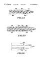
- FIG. 1is a side view, partially in section, of a bypass graft constructed according to the present invention an d secured within a vessel;
- FIGS. 2-7illustrate alternative couplings for mechanically fixing the opposite ends of bypass grafts
- FIG. 8illustrates an alternative embodiment graft incorporating structural supports
- FIGS. 9-16illustrate alternative embodiment grafts incorporating valves
- FIGS. 17 and 18are side sectional views of a bypass graft and system for securing the graft to a vessel wall, in accordance with the present invention.
- FIGS. 19 and 20illustrate tissue dilators of alternative embodiment deployment systems employing thermal bonding
- FIG. 21is a schematic illustration of a circuit for thermal bonding
- FIGS. 22-25illustrate alternative embodiment dilators
- FIG. 26illustrates a tissue perforating needle used with the dilators of the various deployment systems
- FIG. 27is a sectional view of a needle and dilator contained within a catheter
- FIG. 28illustrates an alternative embodiment dilator within a catheter
- FIGS. 29 a-hillustrate a series of steps of a percutaneous deployment and fixation of a bypass graft according to the present invention
- FIGS. 30 a-dillustrate an alternative deployment and fixation procedure
- FIGS. 31 a-cillustrate a farther alternative deployment and fixation
- FIG. 32shows several bypass grafts secured to the heart
- FIGS. 33 and 34illustrate an alternative graft secured within a vessel.
- bypass graft 16secured within a blood vessel 18 , in a manner to bypass a lesion 20 within the vessel.
- Bypass graft 16has a tubular wall 22 formed of a graft material, e.g., a polymer such as PTFE, urethane, polyimide, nylon, silicone, or polyethylene.
- the polymermay be extruded, blow molded, or dipped, and formed either directly into a tubing, or formed first as a sheet having opposed ends or edges bonded together to provide the tubular configuration.
- the edge bondcan be formed by a variety of methods including ultrasonic welding, thermal bonding, sewing, adhesives, or with radio frequency (RF) energy.
- the graftcan be a saphenous vein or other vessel from the patient.
- bypass 16incorporates a radially expandable stent 26 .
- the graftincorporates a similar stent 28 at its distal end region 30 .
- the graft end regionscan have a self-expanding structure, as described in U.S. Pat. No. 6,149,681 entitled “Radially Expanding Prostheses and Systems for Their Deployment,” filed Sep. 20, 1996.
- terminal endsmay be provided that extent partially beyond the graft material.
- the terminal endscan be shaped in a variety of ways, such as in the form of flared end loops. In either event, each stent and its surrounding graft material are expanded into intimate contact with wall 22 of vessel 18 , thus to secure the graft.
- graft 16bypasses lesion 20 , in the sense that a medial region 32 of the graft is disposed outside of vessel 18 .
- the graftcan be considered to exit the vessel at an exit opening or orifice 34 through vessel wall 35 , and re-enter the vessel at a return opening or orifice 36 .
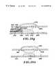
- FIG. 2illustrates an annular collet 38 attached to one end of a graft 40 .
- the colletmay be laminated or bonded to the graft, and is pre-formed to have a segment 42 extending radially beyond the graft. Segment 42 also is collapsible into a low profile to facilitate introduction through vasculature and deployment through the vessel wall. When released, the collet assumes the pre-formed configuration as shown.
- a portion 44 of the graftmay extend along collet segment 42 to secure the vessel wail between the graft material and the collet and provide additional support for attaching the graft to the vessel.
- FIGS. 3 and 4illustrate a collet 46 in which the radially extending collet segment is comprised of eight radially extended collet members 48 .
- a membrane 50may be joined to the collet members to prevent fluid flow through the tissue wall puncture site.
- the colletmay be made of stainless steel, a nickel-titanium alloy or thermoset plastic. It may be constructed with flattened tube nickel-titanium alloy or a braided pattern that is flared.
- FIG. 5shows a further alternative support mechanism in the form of an annular grommet 52 secured to end region 54 of a graft 56 .
- the grommetincorporates a convergence 58 to facilitate insertion through a vessel wall orifice, and a necked down feature 60 to capture the vessel wall immediately about the orifice.
- flexible bands 62can be fixed to an end region of a graft 64 as shown in FIGS. 6 and 7.
- Each band or other flexible memberis compressible into the reduced profile shown in FIG. 6 and remains in that profile while constrained, e.g., by a surrounding catheter.
- band 62assumes the radially enlarged, more circular profile shown in FIG. 7 .
- Pluralities of such bandscan be provided in, crossing patterns at the graft ends, if desired.
- the graftcan incorporate structural support members 66 .
- the support memberscan be constructed of metal or a polymer having a higher modulus of elasticity than the graft material. As shown in FIG. 8, support members 66 can be distributed throughout the graft, with a greater density at the graft end regions to enhance fixation within openings through tissue. Support members 66 can have elliptical or rectangular profiles that enhance their strength in a selected direction.
- support memberscan be used in lieu of stents 26 and 28 for securing graft ends within a vessel.
- the support membersmay be laminated in the graft material. Fabrication can involve extruding or dipping an initial graft layer, winding the support members on the layer, then extruding or dipping to form a second layer covering the support members. Alternatively, the separate layers may be bonded together, or support members may be threaded through the graft material.
- thermal bondingmay be employed to augment the mechanical fixation and form a more positive fluid seal.
- electrode strips 68are mounted to the graft near the graft ends, and coupled through wires 70 to an energy source (e.g., an RF generator) which generates a current to heat adjacent tissue.
- an energy sourcee.g., an RF generator
- the graft edgesare thermally secured to the vessel all by a coagulation of the tissue to the electrode, or by desiccation of the vessel wall to provide an interference fit between the reduced-diameter vessel and the graft, especially where the graft and support members exert a radial force. This better secures the graft to the vessel wall and prevents leaks at the graft edges.
- Suitable materials for the electrodeswhich are body compatible as well as electrically conductive, are platinum, platinum-iridium, stainless steel, and gold.
- signal wires 70are removed from the graft by delivering a D.C. current through the signal wires at an amplitude sufficient to cause a breakdown of the signal wire, e.g., at a reduced-diameter weak point near its associated electrode.
- the signal wirecan be cleaved, or mechanically removed by applying tension to sever the wire at a reduced-diameter neck region.
- FIGS. 9-16show a variety of graft constructions.
- a valve 72includes a valve ball 74 within a surrounding structure that provides a valve seat 76 on one side of the ball, and upper and lower retainers 78 and 80 on the other side of the ball.
- the valveis open and allows flow in the direction of the arrows, around the valve ball and through open spaces between the valve ball and surrounding structure in the area not occupied by the upper and lower retainers.
- valvefunctions as a pressure relief valve in that the flow from left to right as viewed in the figure must be sufficient to overcome the tendency of retainers 78 and 80 to urge the ball valve against the valve seat.
- FIG. 11shows a valve 82 designed to react to the muscular contraction to restore normal vessel function. Muscular contraction forces the valve ends inward, opening the valve to permit fluid flow.
- the force required to open the valvemay be selected, depending on the material, wall thickness, length, and geometry.
- a solid valverequires more force than a valve in which material is selectively removed to maintain the valve function yet decrease the required compressive force to open the valve.
- FIGS. 12-14show a one-way valve 84 having a membrane 86 that closes over valve support struts 88 when no external pressure is present.
- membrane 86distends outwardly away from the struts as seen in FIG. 14, permitting the flow of fluids. Fluid flow in the opposite direction (right to left as viewed in FIGS. 12 and 14) is prevented.
- FIGS. 9-10 and 12 - 14act as pressure relief valves, in the sense that they may be tailored to require a selected force to open them, and they remain open only when the applied pressure exceeds the valve resistance. As a result, these valves characteristically remain open for short periods of time.
- FIGS. 15 and 16show a pressure relief valve 90 that opens due to pressure exerted on the valve, and remains open until a compressive closure force is applied.
- Valve 90includes a plunger 92 movable within a surrounding structure including a valve seat 94 and a knob structure 96 for retaining the valve against the valve seat.
- the outer structurewhich can be the graft itself, includes a flexible section 98 including a protrusion 100 that can be flexed radially inwardly responsive to external pressure.
- the knob structuremaintains the valve closed until pressure against the valve, i.e., acting from left to right as viewed in FIG. 16, exceeds a selected threshold and opens the valve to allow rightward flow. Even after such pressure subsides, the valve remains open until external, radially inward pressure is applied to compress flexible section 98 of the graft. This moves the plunger leftward, returning it beyond the knob structure against the valve seat, thus closing the valve once again.
- Valve 90is particularly well-suited for treating urinary incontinence.
- bladder pressureexceeds the relief valve pressure threshold, the valve is opened to permit the flow of urine.
- muscular contractions or other external squeezingflexes section 98 to return plunger 92 to the valve seat, thus closing the valve.
- Systems for deploying graftsmay require an incision, or alternatively may involve translumenal delivery for a substantially noninvasive procedure.
- the systemmust restrain the graft during introduction through sheathes positioned via the Seldinger technique or a surgical cut-down, advancement through the vasculature and into the target vessel. Unwanted perforations of the vessel or other tissue must be avoided. This requires flexibility to follow a guide wire positioned in the target vessel. Further, the system must facilitate easy and accurate deployment of the graft and delivery components. If a partially deployed graft needs to be altered as to location, the system should permit recapture and repositioning.
- Graft delivery systemsmay incorporate the capacity to mechanically create intimate contact of the graft with surrounded tissue, especially at the graft ends. This capability is discussed in the aforementioned application Ser. No. 08/911,838 entitled “Mechanical Stent and Graft Delivery System.”
- FIGS. 17 and 18show a bypass graft deployment system 102 that requires an incision.
- the systemincludes a dilator 104 having a tapered (distally converging) distal tip 106 .
- a needle 108is mounted coaxially within the dilator, and has a sharp cutting edge 110 for puncturing or perforating tissue.
- a bypass graft 112having a grommet 114 or other suitable fixation mechanism, is supported on and surrounds the dilator.
- Needle 108which can be slideably contained within the dilator if desired, is introduced into the. insertion port and punctures a wall 116 of a vessel 118 on one side of a stenosed lesion 120 .
- the dilatorthen is advanced over the needle to enlarge the puncture to provide an orifice for fixation of the graft.
- graft 112is advanced over the dilator sufficiently to position grommet 114 within the orifice.
- a first region 122 of the graftis secured, so that an opening 124 of the graft is in fluid communication with vessel 118 .
- graft 112has two further openings: an opening 126 surrounded by graft material and a second grommet 128 ; and a more proximally disposed opening 130 , where no grommet or other fixation device is provided.
- the dilator and needleare withdrawn from opening 126 , and further are withdrawn from a region 132 of the graft surrounding opening 130 so that the dilator and needle are completely free of the graft. Then opening 130 , which is provided only to allow access of the dilator and needle, is closed to prevent fluid leakage from the graft.
- One suitable closure mechanismis a purse-string, formed by threading a suture through the graft material in region 132 .
- Other closure mechanismsinclude staples or adhesives.
- the bypass graftmay have four or more openings to accommodate three or more fluid couplings to vasculature or organ cavities.
- FIG. 19shows a dilator 136 with a central lumen 138 for a needle (needle not shown).
- the dilatoralso incorporates a lumen 140 , through which a signal wire can extend for coupling with a dilator electrode 142 .
- Electrode 142delivers RF energy to a grommet 144 at the distal end of a graft 146 surrounding the dilator, thus to thermally secure the grommet to a tissue wall 148 of a vessel 150 .
- a dilator 152includes, along with a central needle lumen 154 , a signal wire lumen 156 and a balloon inflation lumen 158 open to a balloon 160 near the distal end of the dilator.
- the dilatorsupports a surrounding graft 162 having a collet 164 at its distal end.
- balloon 160is inflated to temporarily secure the dilator, which also bends a portion of collet 164 into the retaining position as shown.
- An electrode 170mounted on the exterior of balloon 160 , receives a current from a signal wire contained in lumen 156 , for thermally bonding collet 164 to the surrounding tissue. After thermal bonding, the balloon is deflated and the dilator withdrawn.
- FIG. 21illustrates a schematic circuit for ohmic heating of tissue, useable in conjunction with electrode 170 , other dilator supported electrodes, or electrodes mounted directly to a graft as previously described.
- An RF power generator 174is coupled to the electrode through a signal wire 176 .
- An indifferent electrode 178spaced apart from electrode 170 and typically placed on a patient externally, is coupled to the RF generator through a conductor 180 .
- a currentis generated through tissue between electrodes 170 and 178 , heating the tissue to form the bond.
- FIGS. 22 and 23are sectional views of a distal region of a dilator 182 , taken at different angles to show different lumens through the dilator.
- Lumens 184 and 186 in FIG. 22accommodate signal wires to sensors or transducers 188 and 190 (further discussed below), which can be used to direct placement of the dilator at puncture sites.
- Sensor 188is positioned for axial sensing, while a sensor 190 is oriented for lateral sensing.
- Several sensors 190can be angularly spaced apart from one another about the dilator circumference.
- Lumens 192 and 194shown in FIG. 23, accommodate signal wires 196 to electrodes 198 used for thermal bonding.
- a steering mechanismcan be incorporated into the dilator to facilitate positioning of the dilator and needle for tissue perforations.
- a ring 198is embedded in the dilator distal tip, surrounding needle lumen 200 .
- a wire 202is attached to ring 198 . By pulling wire 202 , the distal tip can be biased downwardly as viewed in the figure.
- magnetsmay be incorporated into the dilator near its distal tip, as indicated at 206 for a dilator 208 shown in FIG. 25 .
- Such magnetsmay be formed of ferrite materials, or alternatively may be formed by winding conductive coils around the dilator to form electromagnets when current is supplied.
- the dilator magnetsare used in conjunction with a guide wire 209 advanced beyond a stenosed lesion 210 within a vessel 212 .
- the guide wireis formed of metal, and to further enhance magnetic attraction may incorporate a magnet 214 of opposite polarity to the dilator magnet. Magnetic positioning facilitates placing bypass grafts through tortuous vessels or over long distances beyond the lesion. Alternatively, known imaging techniques can be used to locate the dilator magnets.
- a needlealso can be provided with steering capability, in particular by forming a hollow needle 216 and securing a wire 218 to a distal portion of a needle through a weld or solder joint 220 .
- a sensor 222 at the needle tip, coupled to wires 224 contained within the needle lumen,can be used to sense a position of the needle tip.
- a further needle enhancementis a stop 226 .
- stop 226limits the degree to which needle 216 can be inserted into tissue, thus preventing excessive, damaging perforations.
- stop 226is collapsible into a diameter substantially the same as that of the needle when the needle is withdrawn into a dilator.
- Intralumenal graft deployment systemsalso utilize dilators and needles as described, but further incorporate catheters.
- a suitable arrangementas shown in FIG. 27, includes a needle 228 surrounded by a dilator 230 , which in turn is surrounded by a catheter 232 , all components being coaxial and circular in profile.
- FIG. 28incorporates non-circular features into a dilator 234 and a lumen of a catheter 236 .
- the non-circular matching featuresallow transmittal of torque from catheter 236 to dilator 234 , enabling selective rotation of the dilator by rotating the catheter.
- FIGS. 29 a - 29 hillustrate progressive steps in a percutaneous, intralumenal deployment of a graft 238 , to bypass a lesion in a vessel 240 .
- the systemincludes a catheter 242 with a lumen 244 containing graft 238 , a dilator 246 and a needle 248 within the dilator.
- the catheter and other componentsare advanced intralumenally to the proximal side of lesion 250 as shown in FIG. 29 a .
- Sensors 252facilitate positioning.
- Such sensorscan include ultrasonic transducers of piezoelectric material, infrared transducers, or fiber-optic elements.
- a radiopaque contrast materialmay be injected to enhance fluoroscopic visualization.
- needle 248is advanced to puncture vessel wall 254 .
- a stop 256restricts movement of a needle if necessary.
- dilator 246is advanced, collapsing stop 256 and enlarging the puncture to provide a suitable orifice through the vessel wall.
- the orifice and dilatortend to form a seal, preventing excess blood leakage as the dilator is advanced along and outside of the vessel.
- the dilatormay have a pre-shaped distal end to facilitate positioning, as shown in FIG. 29 c.
- needle 248is advanced beyond the dilator to puncture vessel wall 254 (FIG. 29 d ).
- stop 256prevents excessive needle advancement, if necessary.
- the stopcan limit needle travel relative to the dilator.
- dilator 246is advanced over the needle (FIG. 29 e ), collapsing the stop and enlarging the puncture by its distal tip, entering the vessel once again.
- needle 248may be completely retracted if desired.
- graft 238then is advanced over dilator 246 , until the graft reenters the vessel, i.e., has its opposite ends contained, each in its respective orifice.
- a collet 258 at the distal end of the graftprevents graft retraction, and a collet 260 anchors the proximal end of the graft.
- the dilatorcan be retracted back into catheter 242 , as shown in FIG. 29 g .
- a hollow stylet 262is used to advance the graft, and also to maintain the graft in place during subsequent withdrawal of the dilator.
- the catheter, stylet and dilatorare withdrawn, leaving graft 238 secured, as seen in FIG. 29 h.
- FIGS. 30 a-dshow an alternative system and graft deployment process, in which a graft 264 is guided to its bypass location within a catheter rather than over a dilator.
- the systemincludes a catheter 266 containing a dilator 268 , which in turn contains a puncturing needle 270 . These components are advanced to a position proximate a lesion 272 within a vessel 274 .
- Dilator 268is pre-formed with a bend at its distal region, and when positioned as shown in FIG. 30 a , is directed upwardly toward the vessel wall as shown, to direct the needle toward the first intended puncture.
- dilator 268can be advanced over the needle, outside of and along the vessel.
- the dilatoris rotated, preferably by the catheter using non-circular profile features as described above, to reorient the tip and point it back toward the vessel as shown in FIG. 30 b .
- Catheter 266is advanced along the dilator, through the orifice and outside of the vessel.
- a balloon 276 surrounding the cathetercan be inflated at this point, to maintain the catheter against proximal withdrawal.
- needle 270is advanced to form the puncture for a re-entry orifice (FIG. 30 c ).
- the dilator tipis used to enlarge the orifice, permitting advancement of the dilator into vessel 274 , followed by advancement of catheter 266 over the dilator, through the orifice and into the vessel as well.
- Balloon 276can be reinflated at this point, to temporarily secure the catheter.
- a graftcan be inserted into the catheter and moved distally along the catheter using a stylet 278 , until the graft reaches a bypass location in which each end of the graft is contained within its respective orifice. Withdrawal of the catheter (not shown), while the stylet maintains the graft in the bypass location, allows collets or other fixation mechanisms to expand and secure the graft.
- This procedureis particularly suited for smaller lesions, where the dilator need travel only a short distance along the vessel.
- FIGS. 31 a-cillustrate a further alternative system and procedure for forming a bypass from a vessel to an organ cavity.
- a catheter 280 containing a dilator 282 and a needle 284is advanced to an intended puncture site 286 within a vessel 288 .
- the punctureis formed as previously described, and the dilator is advanced through tissue to an organ cavity 290 .
- the catheteris advanced over the dilator, becoming open to the cavity as shown in FIG. 31 b .
- Collets 293 and 295secure the catheter.
- a valve 296 within the catheterlimits flow to the direction indicated by the arrow.
- a graft 298 incorporating a valve 300is positioned near lesion 302 , to prevent backflow toward the lesion.
- FIG. 32illustrates two bypass grafts 304 and 306 used to couple the aorta to coronary vasculature in accordance with the present invention.
- FIG. 33illustrates a graft 306 collapsed around a catheter body 308 , deployed in a target vessel across a stenosed lesion 310 .
- the catheter and graftare translumenally advanced to the position shown.
- the opposite ends of the graftcontain expandable stents 314 and 316 , expanded in place with a mechanism such as those described in the aforementioned application Ser. No. 08/911,838.
- the graft endscan have self-expanding characteristics.
- FIG. 34shows the graft expanded.
- the endsare fully expanded into intimate contact with the vessel wall.
- graft 306is expanded only to a nominal diameter.
- the diameteris selected to reduce the flow of resistance and increase cardiac output, yet prevent damage to the endothelial wall. For example, a 50% expansion usually is sufficient to open the vessel while preventing excess damage.
- a large space between the exterior of the graft and the vessel wallaccommodates growth of the stenosed lesion, and tends to contain such growth along the vessel wall so that the vessel remains open.
- graft 308should have inherent radial stability, for example, by employing structural supports as previously discussed.
- graft structural stability and fixationcan be enhanced by forming grafts with two or more layers, with pockets formed between the layers to contain biocompatible foams which solidify when activated to provide further support. Drug solutions also can be provided in such pockets.
- channelsmay be formed through the lesion by cutting a slit through the vessel wall in the targeted region.
- a mechanical deployment system as described in the aforementioned patent application Ser. No. 08/911,838can be used to form the required channel.
- a more easily deployed graftis more reliably secured, to effectively bypass lesions and other blockages.
Landscapes
- Health & Medical Sciences (AREA)
- Life Sciences & Earth Sciences (AREA)
- Veterinary Medicine (AREA)
- Public Health (AREA)
- Cardiology (AREA)
- General Health & Medical Sciences (AREA)
- Engineering & Computer Science (AREA)
- Biomedical Technology (AREA)
- Heart & Thoracic Surgery (AREA)
- Animal Behavior & Ethology (AREA)
- Transplantation (AREA)
- Vascular Medicine (AREA)
- Oral & Maxillofacial Surgery (AREA)
- Pulmonology (AREA)
- Gastroenterology & Hepatology (AREA)
- Surgery (AREA)
- Nuclear Medicine, Radiotherapy & Molecular Imaging (AREA)
- Medical Informatics (AREA)
- Molecular Biology (AREA)
- Prostheses (AREA)
Abstract
Description
Claims (20)
Priority Applications (6)
| Application Number | Priority Date | Filing Date | Title |
|---|---|---|---|
| US09/415,776US6293955B1 (en) | 1996-09-20 | 1999-10-08 | Percutaneous bypass graft and securing system |
| US09/903,219US20010051809A1 (en) | 1996-11-08 | 2001-07-10 | Percutaneous bypass graft and securing system |
| US09/991,455US6652544B2 (en) | 1996-11-08 | 2001-11-21 | Percutaneous bypass graft and securing system |
| US10/243,488US20030014063A1 (en) | 1996-11-08 | 2002-09-12 | Percutaneous bypass graft and securing system |
| US10/243,325US20030014062A1 (en) | 1996-11-08 | 2002-09-12 | Percutaneous bypass graft and securing system |
| US10/243,260US7083631B2 (en) | 1996-11-08 | 2002-09-12 | Percutaneous bypass graft and securing system |
Applications Claiming Priority (6)
| Application Number | Priority Date | Filing Date | Title |
|---|---|---|---|
| US2659296P | 1996-09-20 | 1996-09-20 | |
| US3073396P | 1996-11-08 | 1996-11-08 | |
| US08/932,566US6149681A (en) | 1996-09-20 | 1997-09-19 | Radially expanding prostheses and systems for their deployment |
| US08/966,003US5989276A (en) | 1996-11-08 | 1997-11-07 | Percutaneous bypass graft and securing system |
| US09/415,776US6293955B1 (en) | 1996-09-20 | 1999-10-08 | Percutaneous bypass graft and securing system |
| US64408400A | 2000-08-22 | 2000-08-22 |
Related Parent Applications (2)
| Application Number | Title | Priority Date | Filing Date |
|---|---|---|---|
| US08/966,003ContinuationUS5989276A (en) | 1996-09-20 | 1997-11-07 | Percutaneous bypass graft and securing system |
| US64408400AContinuation-In-Part | 1996-09-20 | 2000-08-22 |
Related Child Applications (1)
| Application Number | Title | Priority Date | Filing Date |
|---|---|---|---|
| US09/903,219ContinuationUS20010051809A1 (en) | 1996-11-08 | 2001-07-10 | Percutaneous bypass graft and securing system |
Publications (1)
| Publication Number | Publication Date |
|---|---|
| US6293955B1true US6293955B1 (en) | 2001-09-25 |
Family
ID=27534163
Family Applications (1)
| Application Number | Title | Priority Date | Filing Date |
|---|---|---|---|
| US09/415,776Expired - Fee RelatedUS6293955B1 (en) | 1996-09-20 | 1999-10-08 | Percutaneous bypass graft and securing system |
Country Status (1)
| Country | Link |
|---|---|
| US (1) | US6293955B1 (en) |
Cited By (103)
| Publication number | Priority date | Publication date | Assignee | Title |
|---|---|---|---|---|
| US20020099394A1 (en)* | 1998-06-10 | 2002-07-25 | Houser Russell A. | Sutureless anastomosis systems |
| US6494889B1 (en) | 1999-09-01 | 2002-12-17 | Converge Medical, Inc. | Additional sutureless anastomosis embodiments |
| US20030014061A1 (en)* | 1996-11-08 | 2003-01-16 | Houser Russell A. | Percutaneous bypass graft and securing system |
| US20030023252A1 (en)* | 2001-07-05 | 2003-01-30 | Whayne James G. | Distal anastomosis system |
| WO2003030744A1 (en)* | 2001-10-09 | 2003-04-17 | Jomed Nv | Coronary bypass apparatus and method |
| US20030093095A1 (en)* | 2001-07-05 | 2003-05-15 | Whayne James G. | Distal anastomosis system |
| US6582444B2 (en) | 1999-08-04 | 2003-06-24 | Percardia, Inc. | Blood flow conduit delivery system and method of use |
| US6605053B1 (en) | 1999-09-10 | 2003-08-12 | Percardia, Inc. | Conduit designs and related methods for optimal flow control |
| US6610100B2 (en) | 1998-09-10 | 2003-08-26 | Percardia, Inc. | Designs for left ventricular conduit |
| US20030167064A1 (en)* | 1999-09-01 | 2003-09-04 | Whayne James G. | Advanced anastomosis systems (II) |
| US20030187499A1 (en)* | 1998-11-06 | 2003-10-02 | Swanson William J. | Medical anastomosis apparatus |
| US6641610B2 (en) | 1998-09-10 | 2003-11-04 | Percardia, Inc. | Valve designs for left ventricular conduits |
| US6652540B1 (en) | 1998-02-13 | 2003-11-25 | Ventrica, Inc. | Methods for forming magnetic vascular anastomoses |
| US20030229365A1 (en)* | 2002-06-10 | 2003-12-11 | Whayne James G. | Angled vascular anastomosis system |
| US6694983B2 (en) | 1998-09-10 | 2004-02-24 | Percardia, Inc. | Delivery methods for left ventricular conduit |
| US6699256B1 (en)* | 1999-06-04 | 2004-03-02 | St. Jude Medical Atg, Inc. | Medical grafting apparatus and methods |
| US20040068278A1 (en)* | 1999-12-06 | 2004-04-08 | Converge Medical Inc. | Anastomosis systems |
| US20040092989A1 (en)* | 2002-08-28 | 2004-05-13 | Heart Leaflet Technologies, Inc | Delivery device for leaflet valve |
| US20040093075A1 (en)* | 2000-12-15 | 2004-05-13 | Titus Kuehne | Stent with valve and method of use thereof |
| US20040106989A1 (en)* | 2002-07-03 | 2004-06-03 | Wilson Robert F. | Leaflet reinforcement for regurgitant valves |
| US20040215233A1 (en)* | 2000-06-16 | 2004-10-28 | Magenta Medical Corporation | Methods and apparatus for forming anastomotic sites |
| US6858035B2 (en) | 2001-07-05 | 2005-02-22 | Converge Medical, Inc. | Distal anastomosis system |
| US20050055022A1 (en)* | 2002-01-25 | 2005-03-10 | Heinrich Schubert | Device for the production of anastomoses between hollow organs |
| US20050131519A1 (en)* | 2003-10-10 | 2005-06-16 | William A. Cook Australia Pty. Ltd. | Composite stent graft |
| US20050154444A1 (en)* | 2003-10-10 | 2005-07-14 | Arshad Quadri | System and method for endoluminal grafting of bifurcated and branched vessels |
| WO2005027736A3 (en)* | 2003-09-15 | 2005-07-21 | Ventrica Inc | Devices and methods for forming magnetic anastomoses between vessels |
| US6945949B2 (en) | 1998-01-30 | 2005-09-20 | Percardia, Inc. | Left ventricular conduits to coronary arteries and methods for coronary bypass |
| US6962595B1 (en) | 2002-01-22 | 2005-11-08 | Cardica, Inc. | Integrated anastomosis system |
| US20050251163A1 (en)* | 2001-07-05 | 2005-11-10 | Converge Medical, Inc. | Vascular anastomosis systems |
| US7004949B2 (en)* | 1998-08-12 | 2006-02-28 | Cardica, Inc. | Method and system for attaching a graft to a blood vessel |
| US20060069401A1 (en)* | 2004-09-27 | 2006-03-30 | Wright David W | Fastener apparatus for tissue and methods of deployment and manufacture |
| US7033372B1 (en) | 1999-08-04 | 2006-04-25 | Percardia, Inc. | Corkscrew reinforced left ventricle to coronary artery channel |
| US20060116625A1 (en)* | 1998-09-10 | 2006-06-01 | Percardia, Inc. | TMR shunt |
| US20070010834A1 (en)* | 2000-04-29 | 2007-01-11 | Sharkawy A A | Components, systems and methods for forming anastomoses using magnetism or other coupling means |
| US7182771B1 (en) | 2001-12-20 | 2007-02-27 | Russell A. Houser | Vascular couplers, techniques, methods, and accessories |
| US7223274B2 (en) | 2002-01-23 | 2007-05-29 | Cardica, Inc. | Method of performing anastomosis |
| US20070203572A1 (en)* | 2006-01-25 | 2007-08-30 | Heuser Richard R | Catheter system with stent apparatus for connecting adjacent blood vessels |
| US7335216B2 (en) | 2002-01-22 | 2008-02-26 | Cardica, Inc. | Tool for creating an opening in tissue |
| US20090125100A1 (en)* | 2007-11-13 | 2009-05-14 | Cook Incorporated | Intraluminal Bypass Prosthesis and Prosthesis Delivery and Deployment Kit |
| US7585306B2 (en) | 2003-12-24 | 2009-09-08 | Maquet Cardiovascular Llc | Anastomosis device, tools and methods of using |
| US7794407B2 (en) | 2006-10-23 | 2010-09-14 | Bard Access Systems, Inc. | Method of locating the tip of a central venous catheter |
| US20110054487A1 (en)* | 2009-09-02 | 2011-03-03 | Circulite, Inc. | Coaxial transseptal guide-wire and needle assembly |
| US20110066170A1 (en)* | 2009-09-14 | 2011-03-17 | Circulite, Inc. | Endovascular anastomotic connector device, delivery system, and methods of delivery and use |
| US7909837B2 (en) | 2000-12-13 | 2011-03-22 | Medtronic, Inc. | Methods, devices and systems for forming magnetic anastomoses |
| US20110087063A1 (en)* | 2009-10-08 | 2011-04-14 | Circulite, Inc. | Two piece endovascular anastomotic connector |
| US8012164B1 (en) | 2002-01-22 | 2011-09-06 | Cardica, Inc. | Method and apparatus for creating an opening in the wall of a tubular vessel |
| US8162963B2 (en) | 2004-06-17 | 2012-04-24 | Maquet Cardiovascular Llc | Angled anastomosis device, tools and method of using |
| US8216298B2 (en) | 2007-01-05 | 2012-07-10 | Medtronic Vascular, Inc. | Branch vessel graft method and delivery system |
| US8388541B2 (en) | 2007-11-26 | 2013-03-05 | C. R. Bard, Inc. | Integrated system for intravascular placement of a catheter |
| US8388546B2 (en) | 2006-10-23 | 2013-03-05 | Bard Access Systems, Inc. | Method of locating the tip of a central venous catheter |
| US8394114B2 (en) | 2003-09-26 | 2013-03-12 | Medtronic, Inc. | Surgical connection apparatus and methods |
| US8414635B2 (en) | 1999-02-01 | 2013-04-09 | Idev Technologies, Inc. | Plain woven stents |
| US8419788B2 (en) | 2006-10-22 | 2013-04-16 | Idev Technologies, Inc. | Secured strand end devices |
| US8437833B2 (en) | 2008-10-07 | 2013-05-07 | Bard Access Systems, Inc. | Percutaneous magnetic gastrostomy |
| US8478382B2 (en) | 2008-02-11 | 2013-07-02 | C. R. Bard, Inc. | Systems and methods for positioning a catheter |
| US8518062B2 (en) | 2000-04-29 | 2013-08-27 | Medtronic, Inc. | Devices and methods for forming magnetic anastomoses between vessels |
| FR2992544A1 (en)* | 2012-07-02 | 2014-01-03 | Perouse Medical | Device for deriving blood flowing through e.g. carotid artery, of patient for removing atherosclerotic plaques, has outer sealing element deployable between contracted configuration against distal conduit and extended use configuration |
| USD699359S1 (en) | 2011-08-09 | 2014-02-11 | C. R. Bard, Inc. | Ultrasound probe head |
| US8690816B2 (en) | 2007-08-02 | 2014-04-08 | Bioconnect Systems, Inc. | Implantable flow connector |
| US20140100510A1 (en)* | 2011-06-15 | 2014-04-10 | Phraxis, Inc. | Anastomotic connector |
| US8781555B2 (en) | 2007-11-26 | 2014-07-15 | C. R. Bard, Inc. | System for placement of a catheter including a signal-generating stylet |
| US8784336B2 (en) | 2005-08-24 | 2014-07-22 | C. R. Bard, Inc. | Stylet apparatuses and methods of manufacture |
| US8801693B2 (en) | 2010-10-29 | 2014-08-12 | C. R. Bard, Inc. | Bioimpedance-assisted placement of a medical device |
| US8849382B2 (en) | 2007-11-26 | 2014-09-30 | C. R. Bard, Inc. | Apparatus and display methods relating to intravascular placement of a catheter |
| US8876881B2 (en) | 2006-10-22 | 2014-11-04 | Idev Technologies, Inc. | Devices for stent advancement |
| USD724745S1 (en) | 2011-08-09 | 2015-03-17 | C. R. Bard, Inc. | Cap for an ultrasound probe |
| US9023095B2 (en) | 2010-05-27 | 2015-05-05 | Idev Technologies, Inc. | Stent delivery system with pusher assembly |
| US9125578B2 (en) | 2009-06-12 | 2015-09-08 | Bard Access Systems, Inc. | Apparatus and method for catheter navigation and tip location |
| US9211107B2 (en) | 2011-11-07 | 2015-12-15 | C. R. Bard, Inc. | Ruggedized ultrasound hydrogel insert |
| US9282967B2 (en) | 2007-08-02 | 2016-03-15 | Bioconnect Systems, Inc. | Implantable flow connector |
| US9339206B2 (en) | 2009-06-12 | 2016-05-17 | Bard Access Systems, Inc. | Adaptor for endovascular electrocardiography |
| US9445734B2 (en) | 2009-06-12 | 2016-09-20 | Bard Access Systems, Inc. | Devices and methods for endovascular electrography |
| US9456766B2 (en) | 2007-11-26 | 2016-10-04 | C. R. Bard, Inc. | Apparatus for use with needle insertion guidance system |
| US9492097B2 (en) | 2007-11-26 | 2016-11-15 | C. R. Bard, Inc. | Needle length determination and calibration for insertion guidance system |
| US9521961B2 (en) | 2007-11-26 | 2016-12-20 | C. R. Bard, Inc. | Systems and methods for guiding a medical instrument |
| US9532724B2 (en) | 2009-06-12 | 2017-01-03 | Bard Access Systems, Inc. | Apparatus and method for catheter navigation using endovascular energy mapping |
| US9554716B2 (en) | 2007-11-26 | 2017-01-31 | C. R. Bard, Inc. | Insertion guidance system for needles and medical components |
| US9636031B2 (en) | 2007-11-26 | 2017-05-02 | C.R. Bard, Inc. | Stylets for use with apparatus for intravascular placement of a catheter |
| US9649048B2 (en) | 2007-11-26 | 2017-05-16 | C. R. Bard, Inc. | Systems and methods for breaching a sterile field for intravascular placement of a catheter |
| US9839372B2 (en) | 2014-02-06 | 2017-12-12 | C. R. Bard, Inc. | Systems and methods for guidance and placement of an intravascular device |
| US9861504B2 (en) | 2016-03-25 | 2018-01-09 | Abbott Cardiovascular Systems Inc. | System and method for renal neuromodulation by adjustable oversized stent |
| US9901714B2 (en) | 2008-08-22 | 2018-02-27 | C. R. Bard, Inc. | Catheter assembly including ECG sensor and magnetic assemblies |
| US9918822B2 (en) | 2015-10-20 | 2018-03-20 | Abbott Cardiovascular Systems Inc. | System and method for renal neuromodulation by oversized stent |
| US10046139B2 (en) | 2010-08-20 | 2018-08-14 | C. R. Bard, Inc. | Reconfirmation of ECG-assisted catheter tip placement |
| US10231838B2 (en) | 2015-08-25 | 2019-03-19 | Innovein, Inc. | Venous valve prosthesis |
| US20190105150A1 (en)* | 2017-10-11 | 2019-04-11 | Aquedeon Medical, Inc. | Systems and methods for treatment of aortic dissection |
| US10349890B2 (en) | 2015-06-26 | 2019-07-16 | C. R. Bard, Inc. | Connector interface for ECG-based catheter positioning system |
| US10434293B2 (en) | 2012-04-15 | 2019-10-08 | Tva Medical, Inc. | Implantable flow connector |
| US10449330B2 (en) | 2007-11-26 | 2019-10-22 | C. R. Bard, Inc. | Magnetic element-equipped needle assemblies |
| US10456239B2 (en) | 2011-06-15 | 2019-10-29 | Phraxis Inc. | Anastomotic connector and system for delivery |
| US10524691B2 (en) | 2007-11-26 | 2020-01-07 | C. R. Bard, Inc. | Needle assembly including an aligned magnetic element |
| US10632293B2 (en) | 2012-04-15 | 2020-04-28 | Tva Medical, Inc. | Delivery system for implantable flow connector |
| US10639008B2 (en) | 2009-10-08 | 2020-05-05 | C. R. Bard, Inc. | Support and cover structures for an ultrasound probe head |
| US10751509B2 (en) | 2007-11-26 | 2020-08-25 | C. R. Bard, Inc. | Iconic representations for guidance of an indwelling medical device |
| US10751056B2 (en) | 2017-10-23 | 2020-08-25 | High Desert Radiology, P.C. | Methods and apparatus for percutaneous bypass graft |
| US10786346B2 (en) | 2012-06-15 | 2020-09-29 | Phraxis Inc. | Arterial anchor devices forming an anastomotic connector |
| US10820885B2 (en) | 2012-06-15 | 2020-11-03 | C. R. Bard, Inc. | Apparatus and methods for detection of a removable cap on an ultrasound probe |
| US10912647B2 (en) | 2015-08-25 | 2021-02-09 | Innovein, Inc. | Vascular valve prosthesis |
| US10973584B2 (en) | 2015-01-19 | 2021-04-13 | Bard Access Systems, Inc. | Device and method for vascular access |
| US10992079B2 (en) | 2018-10-16 | 2021-04-27 | Bard Access Systems, Inc. | Safety-equipped connection systems and methods thereof for establishing electrical connections |
| US11000207B2 (en) | 2016-01-29 | 2021-05-11 | C. R. Bard, Inc. | Multiple coil system for tracking a medical device |
| US11103213B2 (en) | 2009-10-08 | 2021-08-31 | C. R. Bard, Inc. | Spacers for use with an ultrasound probe |
| US11291570B2 (en) | 2018-04-27 | 2022-04-05 | Cook Medical Technologies Llc | Hybrid stent and delivery system |
Citations (88)
| Publication number | Priority date | Publication date | Assignee | Title |
|---|---|---|---|---|
| US4214587A (en) | 1979-02-12 | 1980-07-29 | Sakura Chester Y Jr | Anastomosis device and method |
| US4366819A (en) | 1980-11-17 | 1983-01-04 | Kaster Robert L | Anastomotic fitting |
| US4368736A (en) | 1980-11-17 | 1983-01-18 | Kaster Robert L | Anastomotic fitting |
| US4607637A (en) | 1983-07-22 | 1986-08-26 | Anders Berggren | Surgical instrument for performing anastomosis with the aid of ring-like fastening elements and the fastening elements for performing anastomosis |
| US4624257A (en) | 1982-06-24 | 1986-11-25 | Anders Berggren | Surgical instrument for performing anastomosis |
| US4657019A (en) | 1984-04-10 | 1987-04-14 | Idea Research Investment Fund, Inc. | Anastomosis devices and kits |
| US4665906A (en) | 1983-10-14 | 1987-05-19 | Raychem Corporation | Medical devices incorporating sim alloy elements |
| US4787386A (en) | 1984-04-10 | 1988-11-29 | Idea Research Investment Fund, Inc. | Anastomosis devices, and kits |
| US4917091A (en) | 1982-06-24 | 1990-04-17 | Unilink Ab | Annular fastening means |
| US4917087A (en) | 1984-04-10 | 1990-04-17 | Walsh Manufacturing (Mississuaga) Limited | Anastomosis devices, kits and method |
| US4950227A (en) | 1988-11-07 | 1990-08-21 | Boston Scientific Corporation | Stent delivery system |
| US5067957A (en) | 1983-10-14 | 1991-11-26 | Raychem Corporation | Method of inserting medical devices incorporating SIM alloy elements |
| US5078736A (en) | 1990-05-04 | 1992-01-07 | Interventional Thermodynamics, Inc. | Method and apparatus for maintaining patency in the body passages |
| US5156613A (en) | 1991-02-13 | 1992-10-20 | Interface Biomedical Laboratories Corp. | Collagen welding rod material for use in tissue welding |
| US5190546A (en) | 1983-10-14 | 1993-03-02 | Raychem Corporation | Medical devices incorporating SIM alloy elements |
| US5234447A (en) | 1990-08-28 | 1993-08-10 | Robert L. Kaster | Side-to-end vascular anastomotic staple apparatus |
| US5391156A (en) | 1992-06-30 | 1995-02-21 | Ethicon, Inc. | Flexible encoscopic surgical port |
| US5405322A (en) | 1993-08-12 | 1995-04-11 | Boston Scientific Corporation | Method for treating aneurysms with a thermal source |
| US5443497A (en) | 1993-11-22 | 1995-08-22 | The Johns Hopkins University | Percutaneous prosthetic by-pass graft and method of use |
| US5503635A (en) | 1993-11-12 | 1996-04-02 | United States Surgical Corporation | Apparatus and method for performing compressional anastomoses |
| WO1996022745A1 (en) | 1995-01-23 | 1996-08-01 | Schneider (Usa) Inc. | Percutaneous stent-graft and method for delivery thereof |
| US5571167A (en) | 1991-07-03 | 1996-11-05 | Maginot; Thomas J. | Bypass grafting method |
| WO1997013463A1 (en) | 1995-10-13 | 1997-04-17 | Transvascular, Inc. | Methods and apparatus for bypassing arterial obstructions and/or performing other transvascular procedures |
| WO1997013471A1 (en) | 1995-10-13 | 1997-04-17 | Transvascular, Inc. | A device, system and method for interstitial transvascular intervention |
| WO1997016122A1 (en) | 1995-10-31 | 1997-05-09 | Oticon A/S | Method and anastomotic instrument for use when performing an end-to-side anastomosis |
| US5628784A (en) | 1994-01-18 | 1997-05-13 | Strecker; Ernst P. | Endoprosthesis that can be percutaneously implanted in the body of a patient |
| WO1997027897A1 (en) | 1996-02-02 | 1997-08-07 | Transvascular, Inc. | A device, system and method for interstitial transvascular intervention |
| WO1997027893A1 (en) | 1996-02-02 | 1997-08-07 | Transvascular, Inc. | Methods and apparatus for blocking flow through blood vessels |
| WO1997027898A1 (en) | 1996-02-02 | 1997-08-07 | Transvascular, Inc. | Methods and apparatus for connecting openings formed in adjacent blood vessels or other anatomical structures |
| US5657429A (en) | 1992-08-10 | 1997-08-12 | Computer Motion, Inc. | Automated endoscope system optimal positioning |
| WO1997031575A1 (en) | 1996-02-29 | 1997-09-04 | Oticon A/S | Method and anastomotic instrument for use when performing an end-to-side anastomosis |
| US5665117A (en) | 1995-11-27 | 1997-09-09 | Rhodes; Valentine J. | Endovascular prosthesis with improved sealing means for aneurysmal arterial disease and method of use |
| US5669934A (en) | 1991-02-13 | 1997-09-23 | Fusion Medical Technologies, Inc. | Methods for joining tissue by applying radiofrequency energy to performed collagen films and sheets |
| US5676670A (en) | 1996-06-14 | 1997-10-14 | Beth Israel Deaconess Medical Center | Catheter apparatus and method for creating a vascular bypass in-vivo |
| US5690675A (en) | 1991-02-13 | 1997-11-25 | Fusion Medical Technologies, Inc. | Methods for sealing of staples and other fasteners in tissue |
| WO1997043961A1 (en) | 1996-05-17 | 1997-11-27 | Jan Otto Solem | A by-pass graft |
| US5695504A (en) | 1995-02-24 | 1997-12-09 | Heartport, Inc. | Devices and methods for performing a vascular anastomosis |
| US5697968A (en) | 1995-08-10 | 1997-12-16 | Aeroquip Corporation | Check valve for intraluminal graft |
| US5702418A (en) | 1995-09-12 | 1997-12-30 | Boston Scientific Corporation | Stent delivery system |
| US5720755A (en) | 1995-01-18 | 1998-02-24 | Dakov; Pepi | Tubular suturing device and methods of use |
| US5725544A (en) | 1993-12-23 | 1998-03-10 | Oticon A/S | Method and instrument for establishing the receiving site of a coronary artery bypass graft |
| US5728133A (en) | 1996-07-09 | 1998-03-17 | Cardiologics, L.L.C. | Anchoring device and method for sealing percutaneous punctures in vessels |
| US5749895A (en) | 1991-02-13 | 1998-05-12 | Fusion Medical Technologies, Inc. | Method for bonding or fusion of biological tissue and material |
| US5755778A (en)* | 1996-10-16 | 1998-05-26 | Nitinol Medical Technologies, Inc. | Anastomosis device |
| US5762458A (en) | 1996-02-20 | 1998-06-09 | Computer Motion, Inc. | Method and apparatus for performing minimally invasive cardiac procedures |
| US5779718A (en) | 1992-10-09 | 1998-07-14 | United States Surgical Corporation | Method of anastomosing a vessel using a surgical clip applier |
| US5797920A (en) | 1996-06-14 | 1998-08-25 | Beth Israel Deaconess Medical Center | Catheter apparatus and method using a shape-memory alloy cuff for creating a bypass graft in-vivo |
| US5810884A (en) | 1996-09-09 | 1998-09-22 | Beth Israel Deaconess Medical Center | Apparatus and method for closing a vascular perforation after percutaneous puncture of a blood vessel in a living subject |
| US5814005A (en) | 1991-12-23 | 1998-09-29 | Ela Medical S.A. | Ventricular cannulation device |
| US5824015A (en) | 1991-02-13 | 1998-10-20 | Fusion Medical Technologies, Inc. | Method for welding biological tissue |
| US5861003A (en) | 1996-10-23 | 1999-01-19 | The Cleveland Clinic Foundation | Apparatus and method for occluding a defect or aperture within body surface |
| US5868761A (en) | 1992-10-09 | 1999-02-09 | United States Surgical Corporation | Surgical clip applier |
| US5868759A (en) | 1997-10-10 | 1999-02-09 | United States Surgical Corporation | Surgical clip applier |
| US5871536A (en) | 1993-11-08 | 1999-02-16 | Lazarus; Harrison M. | Intraluminal vascular graft and method |
| US5931842A (en) | 1996-11-07 | 1999-08-03 | Vascular Science Inc. | Methods and apparatus for handling tubing used in medical procedures |
| US5938696A (en) | 1994-02-09 | 1999-08-17 | Boston Scientific Technology, Inc. | Bifurcated endoluminal prosthesis |
| US5938672A (en) | 1996-07-26 | 1999-08-17 | Kensey Nash Corporation | System and method of use for revascularizing stenotic bypass grafts and other blood vessels |
| US5944019A (en) | 1996-08-13 | 1999-08-31 | Heartstent Corporation | Closed chest coronary bypass |
| US5944738A (en) | 1998-02-06 | 1999-08-31 | Aga Medical Corporation | Percutaneous catheter directed constricting occlusion device |
| US5944730A (en) | 1997-05-19 | 1999-08-31 | Cardio Medical Solutions, Inc. | Device and method for assisting end-to-side anastomosis |
| US5944750A (en) | 1997-06-30 | 1999-08-31 | Eva Corporation | Method and apparatus for the surgical repair of aneurysms |
| US5957940A (en) | 1997-06-30 | 1999-09-28 | Eva Corporation | Fasteners for use in the surgical repair of aneurysms |
| US5964782A (en) | 1997-09-18 | 1999-10-12 | Scimed Life Systems, Inc. | Closure device and method |
| US5968090A (en) | 1997-09-08 | 1999-10-19 | United States Surgical Corp. | Endovascular graft and method |
| US5968053A (en) | 1997-01-31 | 1999-10-19 | Cardiac Assist Technologies, Inc. | Method and apparatus for implanting a graft in a vessel of a patient |
| US5968089A (en) | 1996-08-21 | 1999-10-19 | Krajicek; Milan | Internal shield of an anastomosis in a vascular system |
| US5972017A (en) | 1997-04-23 | 1999-10-26 | Vascular Science Inc. | Method of installing tubular medical graft connectors |
| US5972023A (en) | 1994-08-15 | 1999-10-26 | Eva Corporation | Implantation device for an aortic graft method of treating aortic aneurysm |
| US5984955A (en) | 1997-09-11 | 1999-11-16 | Wisselink; Willem | System and method for endoluminal grafting of bifurcated or branched vessels |
| US5989287A (en) | 1998-05-06 | 1999-11-23 | Av Healing Llc | Vascular graft assemblies and methods for implanting same |
| US6001124A (en) | 1997-10-09 | 1999-12-14 | Vascular Science, Inc. | Oblique-angle graft connectors |
| US6007576A (en) | 1998-02-06 | 1999-12-28 | Mcclellan; Scott B. | End to side anastomic implant |
| US6010529A (en) | 1996-12-03 | 2000-01-04 | Atrium Medical Corporation | Expandable shielded vessel support |
| US6017352A (en) | 1997-09-04 | 2000-01-25 | Kensey Nash Corporation | Systems for intravascular procedures and methods of use |
| US6019788A (en) | 1996-11-08 | 2000-02-01 | Gore Enterprise Holdings, Inc. | Vascular shunt graft and junction for same |
| US6030370A (en) | 1997-02-05 | 2000-02-29 | Aesculap Ag And Co. Kg | Surgical instrument |
| US6030392A (en) | 1995-01-18 | 2000-02-29 | Motorola, Inc. | Connector for hollow anatomical structures and methods of use |
| US6036705A (en) | 1997-05-22 | 2000-03-14 | Kensey Nash Corporation | Anastomosis connection system and method of use |
| US6036703A (en) | 1998-02-06 | 2000-03-14 | Ethicon Endo-Surgery Inc. | Method and apparatus for establishing anastomotic passageways |
| US6036702A (en) | 1997-04-23 | 2000-03-14 | Vascular Science Inc. | Medical grafting connectors and fasteners |
| US6048362A (en) | 1998-01-12 | 2000-04-11 | St. Jude Medical Cardiovascular Group, Inc. | Fluoroscopically-visible flexible graft structures |
| US6063114A (en) | 1997-09-04 | 2000-05-16 | Kensey Nash Corporation | Connector system for vessels, ducts, lumens or hollow organs and methods of use |
| US6068654A (en) | 1997-12-23 | 2000-05-30 | Vascular Science, Inc. | T-shaped medical graft connector |
| US6071305A (en) | 1996-11-25 | 2000-06-06 | Alza Corporation | Directional drug delivery stent and method of use |
| US6074416A (en) | 1997-10-09 | 2000-06-13 | St. Jude Medical Cardiovascular Group, Inc. | Wire connector structures for tubular grafts |
| US6113612A (en) | 1998-11-06 | 2000-09-05 | St. Jude Medical Cardiovascular Group, Inc. | Medical anastomosis apparatus |
| US6117147A (en) | 1998-09-30 | 2000-09-12 | Sulzer Carbomedics Inc. | Device and method for reinforcing an anastomotic site |
| US6120432A (en) | 1997-04-23 | 2000-09-19 | Vascular Science Inc. | Medical grafting methods and apparatus |
- 1999
- 1999-10-08USUS09/415,776patent/US6293955B1/ennot_activeExpired - Fee Related
Patent Citations (101)
| Publication number | Priority date | Publication date | Assignee | Title |
|---|---|---|---|---|
| US4214587A (en) | 1979-02-12 | 1980-07-29 | Sakura Chester Y Jr | Anastomosis device and method |
| US4366819A (en) | 1980-11-17 | 1983-01-04 | Kaster Robert L | Anastomotic fitting |
| US4368736A (en) | 1980-11-17 | 1983-01-18 | Kaster Robert L | Anastomotic fitting |
| US4917091A (en) | 1982-06-24 | 1990-04-17 | Unilink Ab | Annular fastening means |
| US4917090A (en) | 1982-06-24 | 1990-04-17 | Unilink, Inc. | Method for performing an anastomosis |
| US4624257A (en) | 1982-06-24 | 1986-11-25 | Anders Berggren | Surgical instrument for performing anastomosis |
| US4607637A (en) | 1983-07-22 | 1986-08-26 | Anders Berggren | Surgical instrument for performing anastomosis with the aid of ring-like fastening elements and the fastening elements for performing anastomosis |
| US5067957A (en) | 1983-10-14 | 1991-11-26 | Raychem Corporation | Method of inserting medical devices incorporating SIM alloy elements |
| US5190546A (en) | 1983-10-14 | 1993-03-02 | Raychem Corporation | Medical devices incorporating SIM alloy elements |
| US4665906A (en) | 1983-10-14 | 1987-05-19 | Raychem Corporation | Medical devices incorporating sim alloy elements |
| US5597378A (en) | 1983-10-14 | 1997-01-28 | Raychem Corporation | Medical devices incorporating SIM alloy elements |
| US4917087A (en) | 1984-04-10 | 1990-04-17 | Walsh Manufacturing (Mississuaga) Limited | Anastomosis devices, kits and method |
| US4787386A (en) | 1984-04-10 | 1988-11-29 | Idea Research Investment Fund, Inc. | Anastomosis devices, and kits |
| US4657019A (en) | 1984-04-10 | 1987-04-14 | Idea Research Investment Fund, Inc. | Anastomosis devices and kits |
| US4950227A (en) | 1988-11-07 | 1990-08-21 | Boston Scientific Corporation | Stent delivery system |
| US5078736A (en) | 1990-05-04 | 1992-01-07 | Interventional Thermodynamics, Inc. | Method and apparatus for maintaining patency in the body passages |
| US5234447A (en) | 1990-08-28 | 1993-08-10 | Robert L. Kaster | Side-to-end vascular anastomotic staple apparatus |
| US5156613A (en) | 1991-02-13 | 1992-10-20 | Interface Biomedical Laboratories Corp. | Collagen welding rod material for use in tissue welding |
| US5690675A (en) | 1991-02-13 | 1997-11-25 | Fusion Medical Technologies, Inc. | Methods for sealing of staples and other fasteners in tissue |
| US5749895A (en) | 1991-02-13 | 1998-05-12 | Fusion Medical Technologies, Inc. | Method for bonding or fusion of biological tissue and material |
| US5669934A (en) | 1991-02-13 | 1997-09-23 | Fusion Medical Technologies, Inc. | Methods for joining tissue by applying radiofrequency energy to performed collagen films and sheets |
| US5824015A (en) | 1991-02-13 | 1998-10-20 | Fusion Medical Technologies, Inc. | Method for welding biological tissue |
| US5979455A (en) | 1991-07-03 | 1999-11-09 | Maginot Vascular Systems | Method for directing blood flow in the body of a patient with a graft and stent assembly |
| US5571167A (en) | 1991-07-03 | 1996-11-05 | Maginot; Thomas J. | Bypass grafting method |
| US5749375A (en) | 1991-07-03 | 1998-05-12 | Maginot; Thomas J. | Method for implanting an end portion of a graft within the body of a patient during a bypass grafting procedure |
| US5934286A (en) | 1991-07-03 | 1999-08-10 | Maginot Vascular Systems | Bypass grafting method which uses a number of balloon catheters to inhibit blood flow to an anastomosis site |
| US5814005A (en) | 1991-12-23 | 1998-09-29 | Ela Medical S.A. | Ventricular cannulation device |
| US5391156A (en) | 1992-06-30 | 1995-02-21 | Ethicon, Inc. | Flexible encoscopic surgical port |
| US5657429A (en) | 1992-08-10 | 1997-08-12 | Computer Motion, Inc. | Automated endoscope system optimal positioning |
| US5779718A (en) | 1992-10-09 | 1998-07-14 | United States Surgical Corporation | Method of anastomosing a vessel using a surgical clip applier |
| US5868761A (en) | 1992-10-09 | 1999-02-09 | United States Surgical Corporation | Surgical clip applier |
| US5405322A (en) | 1993-08-12 | 1995-04-11 | Boston Scientific Corporation | Method for treating aneurysms with a thermal source |
| US5871536A (en) | 1993-11-08 | 1999-02-16 | Lazarus; Harrison M. | Intraluminal vascular graft and method |
| US5503635A (en) | 1993-11-12 | 1996-04-02 | United States Surgical Corporation | Apparatus and method for performing compressional anastomoses |
| US5443497A (en) | 1993-11-22 | 1995-08-22 | The Johns Hopkins University | Percutaneous prosthetic by-pass graft and method of use |
| US5797934A (en) | 1993-12-23 | 1998-08-25 | Oticon A/S | Method, instrument and anastomotic fitting for use when performing an end-to-side anastomosis |
| US5868770A (en) | 1993-12-23 | 1999-02-09 | Oticon A/S | Method and instrument for establishing the receiving site of a coronary artery bypass graft |
| US5725544A (en) | 1993-12-23 | 1998-03-10 | Oticon A/S | Method and instrument for establishing the receiving site of a coronary artery bypass graft |
| US5628784A (en) | 1994-01-18 | 1997-05-13 | Strecker; Ernst P. | Endoprosthesis that can be percutaneously implanted in the body of a patient |
| US5938696A (en) | 1994-02-09 | 1999-08-17 | Boston Scientific Technology, Inc. | Bifurcated endoluminal prosthesis |
| US5972023A (en) | 1994-08-15 | 1999-10-26 | Eva Corporation | Implantation device for an aortic graft method of treating aortic aneurysm |
| US5720755A (en) | 1995-01-18 | 1998-02-24 | Dakov; Pepi | Tubular suturing device and methods of use |
| US6030392A (en) | 1995-01-18 | 2000-02-29 | Motorola, Inc. | Connector for hollow anatomical structures and methods of use |
| WO1996022745A1 (en) | 1995-01-23 | 1996-08-01 | Schneider (Usa) Inc. | Percutaneous stent-graft and method for delivery thereof |
| US5755775A (en) | 1995-01-23 | 1998-05-26 | Schneider (Usa) Inc. | Percutaneous stent-graft and method for delivery thereof |
| US5591226A (en) | 1995-01-23 | 1997-01-07 | Schneider (Usa) Inc. | Percutaneous stent-graft and method for delivery thereof |
| US5695504A (en) | 1995-02-24 | 1997-12-09 | Heartport, Inc. | Devices and methods for performing a vascular anastomosis |
| US5697968A (en) | 1995-08-10 | 1997-12-16 | Aeroquip Corporation | Check valve for intraluminal graft |
| US5702418A (en) | 1995-09-12 | 1997-12-30 | Boston Scientific Corporation | Stent delivery system |
| WO1997013471A1 (en) | 1995-10-13 | 1997-04-17 | Transvascular, Inc. | A device, system and method for interstitial transvascular intervention |
| WO1997013463A1 (en) | 1995-10-13 | 1997-04-17 | Transvascular, Inc. | Methods and apparatus for bypassing arterial obstructions and/or performing other transvascular procedures |
| US5993468A (en) | 1995-10-31 | 1999-11-30 | Oticon A/S | Method and anastomotic instrument for use when performing an end-to-side anastomosis |
| WO1997016122A1 (en) | 1995-10-31 | 1997-05-09 | Oticon A/S | Method and anastomotic instrument for use when performing an end-to-side anastomosis |
| US5665117A (en) | 1995-11-27 | 1997-09-09 | Rhodes; Valentine J. | Endovascular prosthesis with improved sealing means for aneurysmal arterial disease and method of use |
| WO1997027897A1 (en) | 1996-02-02 | 1997-08-07 | Transvascular, Inc. | A device, system and method for interstitial transvascular intervention |
| WO1997027893A1 (en) | 1996-02-02 | 1997-08-07 | Transvascular, Inc. | Methods and apparatus for blocking flow through blood vessels |
| WO1997027898A1 (en) | 1996-02-02 | 1997-08-07 | Transvascular, Inc. | Methods and apparatus for connecting openings formed in adjacent blood vessels or other anatomical structures |
| US5762458A (en) | 1996-02-20 | 1998-06-09 | Computer Motion, Inc. | Method and apparatus for performing minimally invasive cardiac procedures |
| US5954735A (en) | 1996-02-29 | 1999-09-21 | Oticon A/S | Method and anastomotic instrument for use when performing an end-to-side anastomosis |
| WO1997031575A1 (en) | 1996-02-29 | 1997-09-04 | Oticon A/S | Method and anastomotic instrument for use when performing an end-to-side anastomosis |
| WO1997043961A1 (en) | 1996-05-17 | 1997-11-27 | Jan Otto Solem | A by-pass graft |
| US5676670A (en) | 1996-06-14 | 1997-10-14 | Beth Israel Deaconess Medical Center | Catheter apparatus and method for creating a vascular bypass in-vivo |
| US5797920A (en) | 1996-06-14 | 1998-08-25 | Beth Israel Deaconess Medical Center | Catheter apparatus and method using a shape-memory alloy cuff for creating a bypass graft in-vivo |
| US5728133A (en) | 1996-07-09 | 1998-03-17 | Cardiologics, L.L.C. | Anchoring device and method for sealing percutaneous punctures in vessels |
| US5938672A (en) | 1996-07-26 | 1999-08-17 | Kensey Nash Corporation | System and method of use for revascularizing stenotic bypass grafts and other blood vessels |
| US5944019A (en) | 1996-08-13 | 1999-08-31 | Heartstent Corporation | Closed chest coronary bypass |
| US5968089A (en) | 1996-08-21 | 1999-10-19 | Krajicek; Milan | Internal shield of an anastomosis in a vascular system |
| US5810884A (en) | 1996-09-09 | 1998-09-22 | Beth Israel Deaconess Medical Center | Apparatus and method for closing a vascular perforation after percutaneous puncture of a blood vessel in a living subject |
| US5755778A (en)* | 1996-10-16 | 1998-05-26 | Nitinol Medical Technologies, Inc. | Anastomosis device |
| US5861003A (en) | 1996-10-23 | 1999-01-19 | The Cleveland Clinic Foundation | Apparatus and method for occluding a defect or aperture within body surface |
| US5976178A (en) | 1996-11-07 | 1999-11-02 | Vascular Science Inc. | Medical grafting methods |
| US5931842A (en) | 1996-11-07 | 1999-08-03 | Vascular Science Inc. | Methods and apparatus for handling tubing used in medical procedures |
| US6019788A (en) | 1996-11-08 | 2000-02-01 | Gore Enterprise Holdings, Inc. | Vascular shunt graft and junction for same |
| US6071305A (en) | 1996-11-25 | 2000-06-06 | Alza Corporation | Directional drug delivery stent and method of use |
| US6010529A (en) | 1996-12-03 | 2000-01-04 | Atrium Medical Corporation | Expandable shielded vessel support |
| US5968053A (en) | 1997-01-31 | 1999-10-19 | Cardiac Assist Technologies, Inc. | Method and apparatus for implanting a graft in a vessel of a patient |
| US6030370A (en) | 1997-02-05 | 2000-02-29 | Aesculap Ag And Co. Kg | Surgical instrument |
| US6036702A (en) | 1997-04-23 | 2000-03-14 | Vascular Science Inc. | Medical grafting connectors and fasteners |
| US5972017A (en) | 1997-04-23 | 1999-10-26 | Vascular Science Inc. | Method of installing tubular medical graft connectors |
| US6120432A (en) | 1997-04-23 | 2000-09-19 | Vascular Science Inc. | Medical grafting methods and apparatus |
| US5944730A (en) | 1997-05-19 | 1999-08-31 | Cardio Medical Solutions, Inc. | Device and method for assisting end-to-side anastomosis |
| US6056762A (en) | 1997-05-22 | 2000-05-02 | Kensey Nash Corporation | Anastomosis system and method of use |
| US6036705A (en) | 1997-05-22 | 2000-03-14 | Kensey Nash Corporation | Anastomosis connection system and method of use |
| US5957940A (en) | 1997-06-30 | 1999-09-28 | Eva Corporation | Fasteners for use in the surgical repair of aneurysms |
| US5944750A (en) | 1997-06-30 | 1999-08-31 | Eva Corporation | Method and apparatus for the surgical repair of aneurysms |
| US6017352A (en) | 1997-09-04 | 2000-01-25 | Kensey Nash Corporation | Systems for intravascular procedures and methods of use |
| US6063114A (en) | 1997-09-04 | 2000-05-16 | Kensey Nash Corporation | Connector system for vessels, ducts, lumens or hollow organs and methods of use |
| US5968090A (en) | 1997-09-08 | 1999-10-19 | United States Surgical Corp. | Endovascular graft and method |
| US5984955A (en) | 1997-09-11 | 1999-11-16 | Wisselink; Willem | System and method for endoluminal grafting of bifurcated or branched vessels |
| US5964782A (en) | 1997-09-18 | 1999-10-12 | Scimed Life Systems, Inc. | Closure device and method |
| US6074416A (en) | 1997-10-09 | 2000-06-13 | St. Jude Medical Cardiovascular Group, Inc. | Wire connector structures for tubular grafts |
| US6001124A (en) | 1997-10-09 | 1999-12-14 | Vascular Science, Inc. | Oblique-angle graft connectors |
| US5868759A (en) | 1997-10-10 | 1999-02-09 | United States Surgical Corporation | Surgical clip applier |
| US6068654A (en) | 1997-12-23 | 2000-05-30 | Vascular Science, Inc. | T-shaped medical graft connector |
| US6048362A (en) | 1998-01-12 | 2000-04-11 | St. Jude Medical Cardiovascular Group, Inc. | Fluoroscopically-visible flexible graft structures |
| US6036703A (en) | 1998-02-06 | 2000-03-14 | Ethicon Endo-Surgery Inc. | Method and apparatus for establishing anastomotic passageways |
| US5944738A (en) | 1998-02-06 | 1999-08-31 | Aga Medical Corporation | Percutaneous catheter directed constricting occlusion device |
| US6007576A (en) | 1998-02-06 | 1999-12-28 | Mcclellan; Scott B. | End to side anastomic implant |
| US5989287A (en) | 1998-05-06 | 1999-11-23 | Av Healing Llc | Vascular graft assemblies and methods for implanting same |
| US6117147A (en) | 1998-09-30 | 2000-09-12 | Sulzer Carbomedics Inc. | Device and method for reinforcing an anastomotic site |
| US6113612A (en) | 1998-11-06 | 2000-09-05 | St. Jude Medical Cardiovascular Group, Inc. | Medical anastomosis apparatus |
Non-Patent Citations (4)
| Title |
|---|
| Cragg et al. (1982). "Endovascular Diathermic Vessel Occlusion," Radiology 144:303-308. |
| Gorisch et al. (1982). "Heat-Induced Contraction of Blood Vessels," Lasers in Surgery and Medicine 2:1-13. |
| Heijmen et al. (1999). "A Novel One-Shot Anastomotic Stapler Prototype for Coronary Bypass Grafting on the Beating Heart: Feasibility in the Pig," J. Thorac. Cardiovasc Surg. 117:117-125. |
| Yusuf, S. W. et al. (1994). "Transfemoral Endoluminal Repair of Abdominal Aortic Aneurysm with Bifuricated Graft," Lancet 344(8923):650-651. |
Cited By (207)
| Publication number | Priority date | Publication date | Assignee | Title |
|---|---|---|---|---|
| US6652544B2 (en) | 1996-11-08 | 2003-11-25 | Converge Medical, Inc. | Percutaneous bypass graft and securing system |
| US7083631B2 (en) | 1996-11-08 | 2006-08-01 | Converge Medical, Inc. | Percutaneous bypass graft and securing system |
| US20030014061A1 (en)* | 1996-11-08 | 2003-01-16 | Houser Russell A. | Percutaneous bypass graft and securing system |
| US20030014063A1 (en)* | 1996-11-08 | 2003-01-16 | Houser Russell A. | Percutaneous bypass graft and securing system |
| US20030014062A1 (en)* | 1996-11-08 | 2003-01-16 | Houser Russell A. | Percutaneous bypass graft and securing system |
| US6945949B2 (en) | 1998-01-30 | 2005-09-20 | Percardia, Inc. | Left ventricular conduits to coronary arteries and methods for coronary bypass |
| US6949080B2 (en) | 1998-01-30 | 2005-09-27 | Percardia, Inc. | Left ventricular conduits to coronary arteries and methods for coronary bypass |
| US7294115B1 (en) | 1998-01-30 | 2007-11-13 | Percardia, Inc. | Methods of providing direct blood flow between a heart chamber and a coronary vessel |
| US6652540B1 (en) | 1998-02-13 | 2003-11-25 | Ventrica, Inc. | Methods for forming magnetic vascular anastomoses |
| US6887249B1 (en) | 1998-06-10 | 2005-05-03 | Converge Medical Inc. | Positioning systems for sutureless anastomosis systems |
| US20020099394A1 (en)* | 1998-06-10 | 2002-07-25 | Houser Russell A. | Sutureless anastomosis systems |
| US6599302B2 (en) | 1998-06-10 | 2003-07-29 | Converge Medical, Inc. | Aortic aneurysm treatment systems |
| US6740101B2 (en) | 1998-06-10 | 2004-05-25 | Converge Medical, Inc. | Sutureless anastomosis systems |
| US6843795B1 (en) | 1998-06-10 | 2005-01-18 | Converge Medical, Inc. | Anastomotic connector for sutureless anastomosis systems |
| US6648900B2 (en) | 1998-06-10 | 2003-11-18 | Converge Medical, Inc. | Anastomosis systems |
| US6648901B2 (en) | 1998-06-10 | 2003-11-18 | Converge Medical, Inc. | Anastomosis systems |
| US7004949B2 (en)* | 1998-08-12 | 2006-02-28 | Cardica, Inc. | Method and system for attaching a graft to a blood vessel |
| US7041110B2 (en)* | 1998-08-12 | 2006-05-09 | Cardica, Inc. | Method and system for attaching a graft to a blood vessel |
| US6953481B2 (en) | 1998-09-10 | 2005-10-11 | Percardia, Inc. | Designs for left ventricular conduit |
| US6641610B2 (en) | 1998-09-10 | 2003-11-04 | Percardia, Inc. | Valve designs for left ventricular conduits |
| US7347867B2 (en) | 1998-09-10 | 2008-03-25 | Wilk Patent And Development Corporation | Designs for left ventricular conduit |
| US6694983B2 (en) | 1998-09-10 | 2004-02-24 | Percardia, Inc. | Delivery methods for left ventricular conduit |
| US20060116625A1 (en)* | 1998-09-10 | 2006-06-01 | Percardia, Inc. | TMR shunt |
| US7011095B2 (en) | 1998-09-10 | 2006-03-14 | Percardia, Inc. | Valve designs for left ventricular conduits |
| US8187217B2 (en)* | 1998-09-10 | 2012-05-29 | Renati Richard J | TMR shunt |
| US6610100B2 (en) | 1998-09-10 | 2003-08-26 | Percardia, Inc. | Designs for left ventricular conduit |
| US20030187499A1 (en)* | 1998-11-06 | 2003-10-02 | Swanson William J. | Medical anastomosis apparatus |
| US9925074B2 (en) | 1999-02-01 | 2018-03-27 | Board Of Regents, The University Of Texas System | Plain woven stents |
| US8876880B2 (en) | 1999-02-01 | 2014-11-04 | Board Of Regents, The University Of Texas System | Plain woven stents |
| US8974516B2 (en) | 1999-02-01 | 2015-03-10 | Board Of Regents, The University Of Texas System | Plain woven stents |
| US8414635B2 (en) | 1999-02-01 | 2013-04-09 | Idev Technologies, Inc. | Plain woven stents |
| US6699256B1 (en)* | 1999-06-04 | 2004-03-02 | St. Jude Medical Atg, Inc. | Medical grafting apparatus and methods |
| US6582444B2 (en) | 1999-08-04 | 2003-06-24 | Percardia, Inc. | Blood flow conduit delivery system and method of use |
| US7033372B1 (en) | 1999-08-04 | 2006-04-25 | Percardia, Inc. | Corkscrew reinforced left ventricle to coronary artery channel |
| US6494889B1 (en) | 1999-09-01 | 2002-12-17 | Converge Medical, Inc. | Additional sutureless anastomosis embodiments |
| US6702828B2 (en) | 1999-09-01 | 2004-03-09 | Converge Medical, Inc. | Anastomosis system |
| US20030167064A1 (en)* | 1999-09-01 | 2003-09-04 | Whayne James G. | Advanced anastomosis systems (II) |
| US6605053B1 (en) | 1999-09-10 | 2003-08-12 | Percardia, Inc. | Conduit designs and related methods for optimal flow control |
| US20040068278A1 (en)* | 1999-12-06 | 2004-04-08 | Converge Medical Inc. | Anastomosis systems |
| US8518062B2 (en) | 2000-04-29 | 2013-08-27 | Medtronic, Inc. | Devices and methods for forming magnetic anastomoses between vessels |
| US20070010834A1 (en)* | 2000-04-29 | 2007-01-11 | Sharkawy A A | Components, systems and methods for forming anastomoses using magnetism or other coupling means |
| US7938841B2 (en) | 2000-04-29 | 2011-05-10 | Medtronic, Inc. | Components, systems and methods for forming anastomoses using magnetism or other coupling means |
| US7431727B2 (en) | 2000-04-29 | 2008-10-07 | Medtronic, Inc. | Magnetic components for use in forming anastomoses, creating ports in vessels and closing openings in tissue |
| US20040215233A1 (en)* | 2000-06-16 | 2004-10-28 | Magenta Medical Corporation | Methods and apparatus for forming anastomotic sites |
| US7909837B2 (en) | 2000-12-13 | 2011-03-22 | Medtronic, Inc. | Methods, devices and systems for forming magnetic anastomoses |
| US20040093075A1 (en)* | 2000-12-15 | 2004-05-13 | Titus Kuehne | Stent with valve and method of use thereof |
| US20060064119A9 (en)* | 2001-07-05 | 2006-03-23 | Converge Medical, Inc. | Vascular anastomosis systems |
| US6626920B2 (en) | 2001-07-05 | 2003-09-30 | Converge Medical, Inc. | Distal anastomosis system |
| US6972023B2 (en) | 2001-07-05 | 2005-12-06 | Converge Medical, Inc. | Distal anastomosis system |
| US6858035B2 (en) | 2001-07-05 | 2005-02-22 | Converge Medical, Inc. | Distal anastomosis system |
| US20030023252A1 (en)* | 2001-07-05 | 2003-01-30 | Whayne James G. | Distal anastomosis system |
| US20050251163A1 (en)* | 2001-07-05 | 2005-11-10 | Converge Medical, Inc. | Vascular anastomosis systems |
| US20030093095A1 (en)* | 2001-07-05 | 2003-05-15 | Whayne James G. | Distal anastomosis system |
| WO2003030744A1 (en)* | 2001-10-09 | 2003-04-17 | Jomed Nv | Coronary bypass apparatus and method |
| US20090054970A1 (en)* | 2001-12-20 | 2009-02-26 | Cardiovascular Technologies, Inc. | Methods and Devices for Coupling a Device Insertable within a Mammalian Body |
| US7182771B1 (en) | 2001-12-20 | 2007-02-27 | Russell A. Houser | Vascular couplers, techniques, methods, and accessories |
| US20070225642A1 (en)* | 2001-12-20 | 2007-09-27 | Houser Russell A | Catheter Securement Device |
| US7029482B1 (en) | 2002-01-22 | 2006-04-18 | Cardica, Inc. | Integrated anastomosis system |
| US8012164B1 (en) | 2002-01-22 | 2011-09-06 | Cardica, Inc. | Method and apparatus for creating an opening in the wall of a tubular vessel |
| US7455677B2 (en) | 2002-01-22 | 2008-11-25 | Cardica, Inc. | Anastomosis device having a deployable section |
| US7335216B2 (en) | 2002-01-22 | 2008-02-26 | Cardica, Inc. | Tool for creating an opening in tissue |
| US6962595B1 (en) | 2002-01-22 | 2005-11-08 | Cardica, Inc. | Integrated anastomosis system |
| US7223274B2 (en) | 2002-01-23 | 2007-05-29 | Cardica, Inc. | Method of performing anastomosis |
| US20050055022A1 (en)* | 2002-01-25 | 2005-03-10 | Heinrich Schubert | Device for the production of anastomoses between hollow organs |
| US8303610B2 (en)* | 2002-01-25 | 2012-11-06 | Erbe Elektromedizin Gmbh | Device for the production of anastomoses between hollow organs |
| US20030229365A1 (en)* | 2002-06-10 | 2003-12-11 | Whayne James G. | Angled vascular anastomosis system |
| US20040106989A1 (en)* | 2002-07-03 | 2004-06-03 | Wilson Robert F. | Leaflet reinforcement for regurgitant valves |
| US8348963B2 (en) | 2002-07-03 | 2013-01-08 | Hlt, Inc. | Leaflet reinforcement for regurgitant valves |
| US7217287B2 (en) | 2002-08-28 | 2007-05-15 | Heart Leaflet Technologies, Inc. | Method of treating diseased valve |
| US20040092989A1 (en)* | 2002-08-28 | 2004-05-13 | Heart Leaflet Technologies, Inc | Delivery device for leaflet valve |
| US20040092858A1 (en)* | 2002-08-28 | 2004-05-13 | Heart Leaflet Technologies, Inc. | Leaflet valve |
| US8163008B2 (en) | 2002-08-28 | 2012-04-24 | Heart Leaflet Technologies, Inc. | Leaflet valve |
| US7335218B2 (en) | 2002-08-28 | 2008-02-26 | Heart Leaflet Technologies, Inc. | Delivery device for leaflet valve |
| US20040127979A1 (en)* | 2002-08-28 | 2004-07-01 | Heart Leaflet Technologies, Inc | Method of treating diseased valve |
| WO2005027736A3 (en)* | 2003-09-15 | 2005-07-21 | Ventrica Inc | Devices and methods for forming magnetic anastomoses between vessels |
| US8394114B2 (en) | 2003-09-26 | 2013-03-12 | Medtronic, Inc. | Surgical connection apparatus and methods |
| US9943422B2 (en) | 2003-10-10 | 2018-04-17 | Cook Medical Technologies Llc | Composite stent graft |
| US8734501B2 (en)* | 2003-10-10 | 2014-05-27 | Cook Medical Technologies Llc | Composite stent graft |
| US20050131519A1 (en)* | 2003-10-10 | 2005-06-16 | William A. Cook Australia Pty. Ltd. | Composite stent graft |
| US20090012602A1 (en)* | 2003-10-10 | 2009-01-08 | Cardiaq Valve Technologies, Inc. | System and method for endoluminal grafting of bifurcated and branched vessels |
| US7425219B2 (en) | 2003-10-10 | 2008-09-16 | Arshad Quadri | System and method for endoluminal grafting of bifurcated and branched vessels |
| US10195059B2 (en) | 2003-10-10 | 2019-02-05 | Cook Medical Technologies Llc | Composite stent graft |
| US20050154444A1 (en)* | 2003-10-10 | 2005-07-14 | Arshad Quadri | System and method for endoluminal grafting of bifurcated and branched vessels |
| US7585306B2 (en) | 2003-12-24 | 2009-09-08 | Maquet Cardiovascular Llc | Anastomosis device, tools and methods of using |
| US8162963B2 (en) | 2004-06-17 | 2012-04-24 | Maquet Cardiovascular Llc | Angled anastomosis device, tools and method of using |
| US9486216B2 (en) | 2004-09-27 | 2016-11-08 | David W. Wright | Fastener apparatus for tissue and methods of deployment and manufacture |
| US20060069401A1 (en)* | 2004-09-27 | 2006-03-30 | Wright David W | Fastener apparatus for tissue and methods of deployment and manufacture |
| US10004875B2 (en) | 2005-08-24 | 2018-06-26 | C. R. Bard, Inc. | Stylet apparatuses and methods of manufacture |
| US8784336B2 (en) | 2005-08-24 | 2014-07-22 | C. R. Bard, Inc. | Stylet apparatuses and methods of manufacture |
| US11207496B2 (en) | 2005-08-24 | 2021-12-28 | C. R. Bard, Inc. | Stylet apparatuses and methods of manufacture |
| US20070203572A1 (en)* | 2006-01-25 | 2007-08-30 | Heuser Richard R | Catheter system with stent apparatus for connecting adjacent blood vessels |
| US9895242B2 (en) | 2006-10-22 | 2018-02-20 | Idev Technologies, Inc. | Secured strand end devices |
| US9585776B2 (en) | 2006-10-22 | 2017-03-07 | Idev Technologies, Inc. | Secured strand end devices |
| US9149374B2 (en) | 2006-10-22 | 2015-10-06 | Idev Technologies, Inc. | Methods for manufacturing secured strand end devices |
| US9408729B2 (en) | 2006-10-22 | 2016-08-09 | Idev Technologies, Inc. | Secured strand end devices |
| US9408730B2 (en) | 2006-10-22 | 2016-08-09 | Idev Technologies, Inc. | Secured strand end devices |
| US8966733B2 (en) | 2006-10-22 | 2015-03-03 | Idev Technologies, Inc. | Secured strand end devices |
| US8876881B2 (en) | 2006-10-22 | 2014-11-04 | Idev Technologies, Inc. | Devices for stent advancement |
| US10470902B2 (en) | 2006-10-22 | 2019-11-12 | Idev Technologies, Inc. | Secured strand end devices |
| US8739382B2 (en) | 2006-10-22 | 2014-06-03 | Idev Technologies, Inc. | Secured strand end devices |
| US9629736B2 (en) | 2006-10-22 | 2017-04-25 | Idev Technologies, Inc. | Secured strand end devices |
| US8419788B2 (en) | 2006-10-22 | 2013-04-16 | Idev Technologies, Inc. | Secured strand end devices |
| US8388546B2 (en) | 2006-10-23 | 2013-03-05 | Bard Access Systems, Inc. | Method of locating the tip of a central venous catheter |
| US8774907B2 (en) | 2006-10-23 | 2014-07-08 | Bard Access Systems, Inc. | Method of locating the tip of a central venous catheter |
| US8512256B2 (en) | 2006-10-23 | 2013-08-20 | Bard Access Systems, Inc. | Method of locating the tip of a central venous catheter |
| US8858455B2 (en) | 2006-10-23 | 2014-10-14 | Bard Access Systems, Inc. | Method of locating the tip of a central venous catheter |
| US9833169B2 (en) | 2006-10-23 | 2017-12-05 | Bard Access Systems, Inc. | Method of locating the tip of a central venous catheter |
| US9345422B2 (en) | 2006-10-23 | 2016-05-24 | Bard Acess Systems, Inc. | Method of locating the tip of a central venous catheter |
| US7794407B2 (en) | 2006-10-23 | 2010-09-14 | Bard Access Systems, Inc. | Method of locating the tip of a central venous catheter |
| US9265443B2 (en) | 2006-10-23 | 2016-02-23 | Bard Access Systems, Inc. | Method of locating the tip of a central venous catheter |
| US8216298B2 (en) | 2007-01-05 | 2012-07-10 | Medtronic Vascular, Inc. | Branch vessel graft method and delivery system |
| US8690816B2 (en) | 2007-08-02 | 2014-04-08 | Bioconnect Systems, Inc. | Implantable flow connector |
| US10987106B2 (en) | 2007-08-02 | 2021-04-27 | Tva Medical, Inc. | Implantable flow connector |
| US9345485B2 (en) | 2007-08-02 | 2016-05-24 | Bioconnect Systems, Inc. | Implantable flow connector |
| US8961446B2 (en) | 2007-08-02 | 2015-02-24 | Bioconnect Systems Inc. | Implantable flow connector |
| US12232730B2 (en) | 2007-08-02 | 2025-02-25 | Tva Medical, Inc. | Implantable flow connector |
| US9282967B2 (en) | 2007-08-02 | 2016-03-15 | Bioconnect Systems, Inc. | Implantable flow connector |
| US20090125100A1 (en)* | 2007-11-13 | 2009-05-14 | Cook Incorporated | Intraluminal Bypass Prosthesis and Prosthesis Delivery and Deployment Kit |
| US8781555B2 (en) | 2007-11-26 | 2014-07-15 | C. R. Bard, Inc. | System for placement of a catheter including a signal-generating stylet |
| US9554716B2 (en) | 2007-11-26 | 2017-01-31 | C. R. Bard, Inc. | Insertion guidance system for needles and medical components |
| US11779240B2 (en) | 2007-11-26 | 2023-10-10 | C. R. Bard, Inc. | Systems and methods for breaching a sterile field for intravascular placement of a catheter |
| US11707205B2 (en) | 2007-11-26 | 2023-07-25 | C. R. Bard, Inc. | Integrated system for intravascular placement of a catheter |
| US11529070B2 (en) | 2007-11-26 | 2022-12-20 | C. R. Bard, Inc. | System and methods for guiding a medical instrument |
| US11134915B2 (en) | 2007-11-26 | 2021-10-05 | C. R. Bard, Inc. | System for placement of a catheter including a signal-generating stylet |
| US11123099B2 (en) | 2007-11-26 | 2021-09-21 | C. R. Bard, Inc. | Apparatus for use with needle insertion guidance system |
| US9999371B2 (en) | 2007-11-26 | 2018-06-19 | C. R. Bard, Inc. | Integrated system for intravascular placement of a catheter |
| US10966630B2 (en) | 2007-11-26 | 2021-04-06 | C. R. Bard, Inc. | Integrated system for intravascular placement of a catheter |
| US10849695B2 (en) | 2007-11-26 | 2020-12-01 | C. R. Bard, Inc. | Systems and methods for breaching a sterile field for intravascular placement of a catheter |
| US9456766B2 (en) | 2007-11-26 | 2016-10-04 | C. R. Bard, Inc. | Apparatus for use with needle insertion guidance system |
| US10165962B2 (en) | 2007-11-26 | 2019-01-01 | C. R. Bard, Inc. | Integrated systems for intravascular placement of a catheter |
| US9492097B2 (en) | 2007-11-26 | 2016-11-15 | C. R. Bard, Inc. | Needle length determination and calibration for insertion guidance system |
| US9521961B2 (en) | 2007-11-26 | 2016-12-20 | C. R. Bard, Inc. | Systems and methods for guiding a medical instrument |
| US9526440B2 (en) | 2007-11-26 | 2016-12-27 | C.R. Bard, Inc. | System for placement of a catheter including a signal-generating stylet |
| US10751509B2 (en) | 2007-11-26 | 2020-08-25 | C. R. Bard, Inc. | Iconic representations for guidance of an indwelling medical device |
| US9549685B2 (en) | 2007-11-26 | 2017-01-24 | C. R. Bard, Inc. | Apparatus and display methods relating to intravascular placement of a catheter |
| US10105121B2 (en) | 2007-11-26 | 2018-10-23 | C. R. Bard, Inc. | System for placement of a catheter including a signal-generating stylet |
| US8849382B2 (en) | 2007-11-26 | 2014-09-30 | C. R. Bard, Inc. | Apparatus and display methods relating to intravascular placement of a catheter |
| US10602958B2 (en) | 2007-11-26 | 2020-03-31 | C. R. Bard, Inc. | Systems and methods for guiding a medical instrument |
| US10524691B2 (en) | 2007-11-26 | 2020-01-07 | C. R. Bard, Inc. | Needle assembly including an aligned magnetic element |
| US9636031B2 (en) | 2007-11-26 | 2017-05-02 | C.R. Bard, Inc. | Stylets for use with apparatus for intravascular placement of a catheter |
| US9649048B2 (en) | 2007-11-26 | 2017-05-16 | C. R. Bard, Inc. | Systems and methods for breaching a sterile field for intravascular placement of a catheter |
| US9681823B2 (en) | 2007-11-26 | 2017-06-20 | C. R. Bard, Inc. | Integrated system for intravascular placement of a catheter |
| US10449330B2 (en) | 2007-11-26 | 2019-10-22 | C. R. Bard, Inc. | Magnetic element-equipped needle assemblies |
| US10342575B2 (en) | 2007-11-26 | 2019-07-09 | C. R. Bard, Inc. | Apparatus for use with needle insertion guidance system |
| US10238418B2 (en) | 2007-11-26 | 2019-03-26 | C. R. Bard, Inc. | Apparatus for use with needle insertion guidance system |
| US10231753B2 (en) | 2007-11-26 | 2019-03-19 | C. R. Bard, Inc. | Insertion guidance system for needles and medical components |
| US8388541B2 (en) | 2007-11-26 | 2013-03-05 | C. R. Bard, Inc. | Integrated system for intravascular placement of a catheter |
| US8971994B2 (en) | 2008-02-11 | 2015-03-03 | C. R. Bard, Inc. | Systems and methods for positioning a catheter |
| US8478382B2 (en) | 2008-02-11 | 2013-07-02 | C. R. Bard, Inc. | Systems and methods for positioning a catheter |
| US9901714B2 (en) | 2008-08-22 | 2018-02-27 | C. R. Bard, Inc. | Catheter assembly including ECG sensor and magnetic assemblies |
| US11027101B2 (en) | 2008-08-22 | 2021-06-08 | C. R. Bard, Inc. | Catheter assembly including ECG sensor and magnetic assemblies |
| US9907513B2 (en) | 2008-10-07 | 2018-03-06 | Bard Access Systems, Inc. | Percutaneous magnetic gastrostomy |
| US8437833B2 (en) | 2008-10-07 | 2013-05-07 | Bard Access Systems, Inc. | Percutaneous magnetic gastrostomy |
| US10271762B2 (en) | 2009-06-12 | 2019-04-30 | Bard Access Systems, Inc. | Apparatus and method for catheter navigation using endovascular energy mapping |
| US9445734B2 (en) | 2009-06-12 | 2016-09-20 | Bard Access Systems, Inc. | Devices and methods for endovascular electrography |
| US10912488B2 (en) | 2009-06-12 | 2021-02-09 | Bard Access Systems, Inc. | Apparatus and method for catheter navigation and tip location |
| US9532724B2 (en) | 2009-06-12 | 2017-01-03 | Bard Access Systems, Inc. | Apparatus and method for catheter navigation using endovascular energy mapping |
| US9339206B2 (en) | 2009-06-12 | 2016-05-17 | Bard Access Systems, Inc. | Adaptor for endovascular electrocardiography |
| US10231643B2 (en) | 2009-06-12 | 2019-03-19 | Bard Access Systems, Inc. | Apparatus and method for catheter navigation and tip location |
| US9125578B2 (en) | 2009-06-12 | 2015-09-08 | Bard Access Systems, Inc. | Apparatus and method for catheter navigation and tip location |
| US11419517B2 (en) | 2009-06-12 | 2022-08-23 | Bard Access Systems, Inc. | Apparatus and method for catheter navigation using endovascular energy mapping |
| US20110054487A1 (en)* | 2009-09-02 | 2011-03-03 | Circulite, Inc. | Coaxial transseptal guide-wire and needle assembly |
| US9050419B2 (en) | 2009-09-14 | 2015-06-09 | Circulite, Inc. | Endovascular anastomotic connector device, delivery system, and methods of delivery and use |
| US20110066170A1 (en)* | 2009-09-14 | 2011-03-17 | Circulite, Inc. | Endovascular anastomotic connector device, delivery system, and methods of delivery and use |
| US11241231B2 (en) | 2009-09-14 | 2022-02-08 | Circulite, Inc. | Endovascular anastomotic connector device, delivery system, and methods of delivery and use |
| US11103213B2 (en) | 2009-10-08 | 2021-08-31 | C. R. Bard, Inc. | Spacers for use with an ultrasound probe |
| US8333727B2 (en) | 2009-10-08 | 2012-12-18 | Circulite, Inc. | Two piece endovascular anastomotic connector |
| US20110087063A1 (en)* | 2009-10-08 | 2011-04-14 | Circulite, Inc. | Two piece endovascular anastomotic connector |
| US10639008B2 (en) | 2009-10-08 | 2020-05-05 | C. R. Bard, Inc. | Support and cover structures for an ultrasound probe head |
| US11998386B2 (en) | 2009-10-08 | 2024-06-04 | C. R. Bard, Inc. | Support and cover structures for an ultrasound probe head |
| US9023095B2 (en) | 2010-05-27 | 2015-05-05 | Idev Technologies, Inc. | Stent delivery system with pusher assembly |
| US12121460B2 (en) | 2010-05-27 | 2024-10-22 | Idev Technologies, Inc. | Stent delivery system with pusher assembly |
| US10046139B2 (en) | 2010-08-20 | 2018-08-14 | C. R. Bard, Inc. | Reconfirmation of ECG-assisted catheter tip placement |
| US8801693B2 (en) | 2010-10-29 | 2014-08-12 | C. R. Bard, Inc. | Bioimpedance-assisted placement of a medical device |
| US9415188B2 (en) | 2010-10-29 | 2016-08-16 | C. R. Bard, Inc. | Bioimpedance-assisted placement of a medical device |
| US20140100510A1 (en)* | 2011-06-15 | 2014-04-10 | Phraxis, Inc. | Anastomotic connector |
| US9597443B2 (en)* | 2011-06-15 | 2017-03-21 | Phraxis, Inc. | Anastomotic connector |
| US10456239B2 (en) | 2011-06-15 | 2019-10-29 | Phraxis Inc. | Anastomotic connector and system for delivery |
| USD724745S1 (en) | 2011-08-09 | 2015-03-17 | C. R. Bard, Inc. | Cap for an ultrasound probe |
| USD754357S1 (en) | 2011-08-09 | 2016-04-19 | C. R. Bard, Inc. | Ultrasound probe head |
| USD699359S1 (en) | 2011-08-09 | 2014-02-11 | C. R. Bard, Inc. | Ultrasound probe head |
| US9211107B2 (en) | 2011-11-07 | 2015-12-15 | C. R. Bard, Inc. | Ruggedized ultrasound hydrogel insert |
| US10632293B2 (en) | 2012-04-15 | 2020-04-28 | Tva Medical, Inc. | Delivery system for implantable flow connector |
| US11666737B2 (en) | 2012-04-15 | 2023-06-06 | Tva Medical, Inc. | Implantable flow connector |
| US11541213B2 (en) | 2012-04-15 | 2023-01-03 | Tva Medical, Inc. | Delivery system for implantable flow connector |
| US10434293B2 (en) | 2012-04-15 | 2019-10-08 | Tva Medical, Inc. | Implantable flow connector |
| US10820885B2 (en) | 2012-06-15 | 2020-11-03 | C. R. Bard, Inc. | Apparatus and methods for detection of a removable cap on an ultrasound probe |
| US10786346B2 (en) | 2012-06-15 | 2020-09-29 | Phraxis Inc. | Arterial anchor devices forming an anastomotic connector |
| US11020215B2 (en) | 2012-06-15 | 2021-06-01 | Phraxis, Inc. | Venous anchor devices forming an anastomotic connector |
| FR2992544A1 (en)* | 2012-07-02 | 2014-01-03 | Perouse Medical | Device for deriving blood flowing through e.g. carotid artery, of patient for removing atherosclerotic plaques, has outer sealing element deployable between contracted configuration against distal conduit and extended use configuration |
| US10835366B2 (en) | 2012-08-16 | 2020-11-17 | Phraxis Inc. | Arterial and venous anchor devices forming an anastomotic connector and system for delivery |
| US10863920B2 (en) | 2014-02-06 | 2020-12-15 | C. R. Bard, Inc. | Systems and methods for guidance and placement of an intravascular device |
| US9839372B2 (en) | 2014-02-06 | 2017-12-12 | C. R. Bard, Inc. | Systems and methods for guidance and placement of an intravascular device |
| US10973584B2 (en) | 2015-01-19 | 2021-04-13 | Bard Access Systems, Inc. | Device and method for vascular access |
| US11026630B2 (en) | 2015-06-26 | 2021-06-08 | C. R. Bard, Inc. | Connector interface for ECG-based catheter positioning system |
| US10349890B2 (en) | 2015-06-26 | 2019-07-16 | C. R. Bard, Inc. | Connector interface for ECG-based catheter positioning system |
| US11564797B2 (en) | 2015-08-25 | 2023-01-31 | Innovein, Inc. | Venous valve prosthesis |
| US10231838B2 (en) | 2015-08-25 | 2019-03-19 | Innovein, Inc. | Venous valve prosthesis |
| US10912647B2 (en) | 2015-08-25 | 2021-02-09 | Innovein, Inc. | Vascular valve prosthesis |
| US9918822B2 (en) | 2015-10-20 | 2018-03-20 | Abbott Cardiovascular Systems Inc. | System and method for renal neuromodulation by oversized stent |
| US11000207B2 (en) | 2016-01-29 | 2021-05-11 | C. R. Bard, Inc. | Multiple coil system for tracking a medical device |
| US9861504B2 (en) | 2016-03-25 | 2018-01-09 | Abbott Cardiovascular Systems Inc. | System and method for renal neuromodulation by adjustable oversized stent |
| US20190105150A1 (en)* | 2017-10-11 | 2019-04-11 | Aquedeon Medical, Inc. | Systems and methods for treatment of aortic dissection |
| US10751056B2 (en) | 2017-10-23 | 2020-08-25 | High Desert Radiology, P.C. | Methods and apparatus for percutaneous bypass graft |
| US11291570B2 (en) | 2018-04-27 | 2022-04-05 | Cook Medical Technologies Llc | Hybrid stent and delivery system |
| US11621518B2 (en) | 2018-10-16 | 2023-04-04 | Bard Access Systems, Inc. | Safety-equipped connection systems and methods thereof for establishing electrical connections |
| US10992079B2 (en) | 2018-10-16 | 2021-04-27 | Bard Access Systems, Inc. | Safety-equipped connection systems and methods thereof for establishing electrical connections |
Similar Documents
| Publication | Publication Date | Title |
|---|---|---|
| US6293955B1 (en) | Percutaneous bypass graft and securing system | |
| US6652544B2 (en) | Percutaneous bypass graft and securing system | |
| US20230270538A1 (en) | Methods and systems for providing or maintaining fluid flow through body passages | |
| AU2021232831B2 (en) | Fenestration devices, systems, and methods | |
| US7169164B2 (en) | Apparatus for implanting devices in atrial appendages | |
| US20020033180A1 (en) | Device, an introducer and a method for providing a supplemental flow of blood | |
| US20070010781A1 (en) | Implantable aorto-coronary sinus shunt for myocardial revascularization | |
| WO2007002616A2 (en) | Implantable aorto-coronary sinus shunt for myocardial revascularization and method of usng the same |
Legal Events
| Date | Code | Title | Description |
|---|---|---|---|
| AS | Assignment | Owner name:EDWARDS LIFESCIENCES, LLC, CALIFORNIA Free format text:SECURITY INTEREST;ASSIGNOR:CONVERGE MEDICAL, INC.;REEL/FRAME:014025/0421 Effective date:20030917 Owner name:FORWARD VENTURES IV B, L.P., CALIFORNIA Free format text:SECURITY INTEREST;ASSIGNOR:CONVERGE MEDICAL, INC.;REEL/FRAME:014025/0421 Effective date:20030917 Owner name:FORWARD VENTURES IV, L.P., CALIFORNIA Free format text:SECURITY INTEREST;ASSIGNOR:CONVERGE MEDICAL, INC.;REEL/FRAME:014025/0421 Effective date:20030917 Owner name:HAMILTON TECHNOLOGY VENTURES L.P., CALIFORNIA Free format text:SECURITY INTEREST;ASSIGNOR:CONVERGE MEDICAL, INC.;REEL/FRAME:014025/0421 Effective date:20030917 Owner name:JAFCO G-8 (A) INVESTMENT ENTERPRISE PARTNERSHIP, J Free format text:SECURITY INTEREST;ASSIGNOR:CONVERGE MEDICAL, INC.;REEL/FRAME:014025/0421 Effective date:20030917 Owner name:JAFCO G-8 (B) INVESTMENT ENTERPRISE PARTNERSHIP, J Free format text:SECURITY INTEREST;ASSIGNOR:CONVERGE MEDICAL, INC.;REEL/FRAME:014025/0421 Effective date:20030917 Owner name:JAFCO GC-1 INVESTMENT ENTERPRISE PARTNERSHIP, JAPA Free format text:SECURITY INTEREST;ASSIGNOR:CONVERGE MEDICAL, INC.;REEL/FRAME:014025/0421 Effective date:20030917 Owner name:ST. PAUL VENTURE CAPITAL VI, LLC, MINNESOTA Free format text:SECURITY INTEREST;ASSIGNOR:CONVERGE MEDICAL, INC.;REEL/FRAME:014025/0421 Effective date:20030917 | |
| AS | Assignment | Owner name:CONVERGE MEDICAL, INC., CALIFORNIA Free format text:RELEASE OF SECURITY AGREEMENT;ASSIGNORS:ST. PAUL VENTURE CAPITAL VI, LLC;FORWARD VENTURES IV, LP;FORWARD VENTURES IV B, LP;AND OTHERS;REEL/FRAME:014128/0591 Effective date:20031022 | |
| FPAY | Fee payment | Year of fee payment:4 | |
| CC | Certificate of correction | ||
| REMI | Maintenance fee reminder mailed | ||
| LAPS | Lapse for failure to pay maintenance fees | ||
| STCH | Information on status: patent discontinuation | Free format text:PATENT EXPIRED DUE TO NONPAYMENT OF MAINTENANCE FEES UNDER 37 CFR 1.362 | |
| FP | Lapsed due to failure to pay maintenance fee | Effective date:20090925 |