US6292713B1 - Robotic telepresence system - Google Patents
Robotic telepresence systemDownload PDFInfo
- Publication number
- US6292713B1 US6292713B1US09/315,759US31575999AUS6292713B1US 6292713 B1US6292713 B1US 6292713B1US 31575999 AUS31575999 AUS 31575999AUS 6292713 B1US6292713 B1US 6292713B1
- Authority
- US
- United States
- Prior art keywords
- user
- robot
- image
- low resolution
- display
- Prior art date
- Legal status (The legal status is an assumption and is not a legal conclusion. Google has not performed a legal analysis and makes no representation as to the accuracy of the status listed.)
- Expired - Lifetime
Links
Images


Classifications
- G—PHYSICS
- G06—COMPUTING OR CALCULATING; COUNTING
- G06F—ELECTRIC DIGITAL DATA PROCESSING
- G06F3/00—Input arrangements for transferring data to be processed into a form capable of being handled by the computer; Output arrangements for transferring data from processing unit to output unit, e.g. interface arrangements
- G06F3/01—Input arrangements or combined input and output arrangements for interaction between user and computer
- G06F3/011—Arrangements for interaction with the human body, e.g. for user immersion in virtual reality
- G—PHYSICS
- G06—COMPUTING OR CALCULATING; COUNTING
- G06F—ELECTRIC DIGITAL DATA PROCESSING
- G06F3/00—Input arrangements for transferring data to be processed into a form capable of being handled by the computer; Output arrangements for transferring data from processing unit to output unit, e.g. interface arrangements
- G06F3/14—Digital output to display device ; Cooperation and interconnection of the display device with other functional units
- G06F3/1423—Digital output to display device ; Cooperation and interconnection of the display device with other functional units controlling a plurality of local displays, e.g. CRT and flat panel display
- G06F3/1446—Digital output to display device ; Cooperation and interconnection of the display device with other functional units controlling a plurality of local displays, e.g. CRT and flat panel display display composed of modules, e.g. video walls
Definitions
- the present inventionrelates generally to robotics, and particularly to a robotic telepresence system.
- a remotely controlled robotsimulates the presence of a user.
- the overall experience for the user and the people interacting with the robotic telepresence deviceis similar to videoconferencing, except that the user has a freedom of motion and control over the robot and video input that is not present in traditional videoconferencing.
- the robot platformtypically includes a camera, a display device, a motorized platform that includes batteries, a control computer, and a wireless computer network connection.
- An image of the useris displayed on the robotic telepresence device's display. This image is captured by a camera at the user's location.
- a robotic deviceis built on a remote controlled car.
- driving the car remotelyis considerably more difficult than personally walking through the same area.
- the robotic deviceuses a single small camera with a relatively small field of view and low resolution.
- This deviceshares problems with videoconferencing in that the user has “tunnel vision.”
- the useris not provided with a peripheral view or the environment as compared to human peripheral vision.
- the central resolution of the remote camerais much lower than that of the human eye, which makes it difficult to remotely read anything other than very large text.
- the robotic devicedisplays the user's image on a small LCD screen about three inches tall which does not move independently of the robotic platform. This display does not provide an appearance of eye contact between the remote user and others interacting with the remote user via the robot. The lack of eye contact makes it difficult for people to relate naturally to the person using the robotic device.
- a robotic telepresence systemhas a user station at a first geographic location and a robot at a second geographic location.
- the user stationis responsive to a user and communicates information to and from the user.
- the robotis coupled to the user station and provides a three dimensional representation of the user transmitted from the user station.
- the robotalso senses predetermined types of information and communicates the sensed information back to the user.
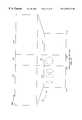
- FIG. 1is a diagram of a robotic telepresence system of the present invention.
- FIG. 2is perspective view of one embodiment of the robot of FIG. 1 .
- FIG. 3Ais a top view of the camera arrangement on the robot of FIG. 2 .
- FIG. 3Bis a top view of an alternate camera arrangement used with the robot of FIG. 2 .
- FIG. 4is a diagram illustrating the use of the robot of FIG. 2 in a conference room with the overlay of the user's head on a background image.
- FIG. 5Ais diagram of the display of the robot of FIG. 2 in the conference room of FIG. 4 illustrating the display of a texture map of a front view of user's head onto a front display.
- FIG. 5Bis diagram of the display of the robot of FIG. 2 in the conference room of FIG. 4 illustrating the display of the texture map of the user's side profile onto a side display.
- FIG. 5Cis diagram of the display of the robot of FIG. 2 in the conference room of FIG. 4 illustrating the display of the texture map of the user's other side profile onto another side display.
- FIG. 6is a flowchart illustrating a method of tracking the user's head using a pre-compression technique.
- FIG. 7is a flowchart illustrating a method of tracking the user's head using a postcompression technique.
- FIG. 8Ais a diagram of a display using foveal video.
- FIG. 8Bis a diagram of a display using foveal video in two dimensions.
- FIG. 8Cis a diagram of a display using multi-resolution foveal video.
- FIG. 9is a flowchart of a general method of displaying images using foveal video in a seamless display.
- FIG. 10is a flowchart of a detailed method of displaying images using foveal video in a seamless display.
- FIG. 11is a flowchart of an alternate method of displaying images using foveal video with a border identifying the high resolution image that is used with the method of FIG. 9 .
- FIG. 12is a diagram of a display using foveal video with an intensity map for a section of the display.
- FIG. 13is a diagram illustrating the mapping of a set of images into a display using abrupt anamorphic video.
- FIG. 14is a diagram of a display using abrupt anamorphic video in two dimensions.
- FIG. 15is a flowchart of the method of displaying an image using visually abrupt anamorphic video.
- FIG. 16is a flowchart of the method of displaying an image using graduated anamorphic video.
- FIG. 17is a diagram illustrating the mapping of a set of images on a display using graduated anamorphic video.
- FIG. 18is a diagram of a display using two-dimensional graduated anamorphic video.
- FIG. 19is a diagram of a display that combines foveal and anamorphic video in a single image.
- FIG. 20is a flowchart for additional digital imaging to be applied to received images to correct for lens barrel distortion and lens light fall off.
- FIG. 21illustrates the effect of lens barrel distortion
- FIG. 22illustrates the extent of the lens barrel distortion.
- FIG. 23is an image corrected for lens barrel distortion.
- FIG. 24is a lens intensity map for lens light falloff.
- FIG. 25is an opacity map used in a texture mapping technique for correcting for lens light falloff.
- FIG. 26is a diagram of a user station showing the camera configuration.
- FIG. 27is a diagram of the user station of FIG. 26 implemented with a partially-reflective mirror to improve eye-contact with the user.
- FIG. 28is a diagram of an immersion room.
- FIG. 29is a top down view of the immersion room showing the location of the user, projectors, cameras and mirrors.
- FIG. 30is a diagram illustrating the keystone effect.
- FIG. 31illustrates the keystone effect using a side view of one projector configuration in the immersion room of FIG. 28 .
- FIG. 32is a flowchart of a method for correcting for keystone effect in the display.
- FIG. 33is a diagram of the computer system of the user station and/or immersion room with procedures implementing the methods of the present invention in memory.
- FIG. 34is a diagram of the computer system of the robot with procedures implementing the methods of the present invention in memory.
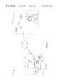
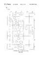
- a robotic telepresence system 40has a user station 50 at a first geographic location 52 and a robot 60 at a second geographic location 62 .
- the user station 50is responsive to a user and communicates information to and receives information from the user.
- the robot 60is responsive to commands from the user station 50 and provides a three dimensional representation of the user and audio from the user which is transmitted by the user station 50 .
- the robot 60also senses predetermined types of information and communicates the sensed information back to the user station 50 .
- the user station 50provides an image from a camera on the robot 60 , as well as audio from the robot 60 .
- the user station 50is implemented using a computer system 64 .
- the computer system 64has a central processing unit (CPU) 66 , keyboard 68 , display 70 , mouse 72 and joystick 73 .
- the computer system 64has a communications interface to a communications medium 74 .
- the communications medium 74is a public network such as the Internet. Alternately, the communications medium 74 includes a private network, or a combination of public and private networks.
- the robot 60is coupled to the communications medium 74 via a wireless transmitter/receiver 76 on the robot 60 and at least one corresponding wireless transmitter/receiver base station 78 that is placed sufficiently near the robot 60 to transmit and receive signals as the robot 60 moves.
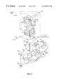
- a control computer (CPU) 80is coupled to and controls a camera array 82 , a display 84 , at least one distance sensor 85 , an accelerometer 86 , the wireless computer transmitter/receiver 76 , and a motorized assembly 88 .
- the motorized assembly 88includes a platform 90 with a motor 92 that is coupled to wheels 94 .
- the control computer 80is also coupled to and controls speaker 96 and microphone 98 .
- the platform 90supports a power supply 100 including batteries for supplying power to the control computer 80 , the motor 92 , the display 84 and the camera array 82 .
- An image of the user 102is displayed on the robot's display 84 .
- the user's imageis captured by one or more cameras at the user's location.
- the robot 60has at least one first sensor 104 to sense information at a first predetermined high resolution level, and at least one second sensor 106 - 114 to sense information at a predetermined low resolution level.
- at least one high resolution camera 104senses video information at a first predetermined high resolution level
- at least one low resolution camera 106 , 108 , 110 , 112 , 114senses video information at a predetermined low resolution level.
- the high resolution imagehas a pixel density that is at least two times the pixel density of the low resolution images.
- one pixelrepresents an area of six arc-minutes by six arc-minutes.
- an area of 1° by 1°is represented by 100 pixels.
- one pixelrepresents an area of twelve arc-minutes by twelve arc-minutes.
- an area of 1° by 1°is represented by 25 pixels.
- All or a portion of the video images from all or a subset of the cameras 104 - 114is transmitted from the robot 60 to the user station 50 (FIG. 1 ).
- the high resolution camera 104is physically aligned with the motorized assembly 88 in a forward direction of travel.
- the robot 60transmits high resolution images to the user in a direction of travel.
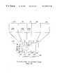
- the robot 60has a “head” 115 that includes the camera array 82 and the display 84 .
- the head 115 with the camera array 82is mounted on a shaft 116 which is coupled to a motor 118 .
- the control computer 80activates the motor 118 which turns the shaft 116 with the camera array 82 .
- the useris provided with a way of using the robot's high resolution camera 104 to look around. For example, if the robot 60 were traveling down a hall, the high resolution camera could be looking at one side of the hall to allow the user to read office numbers ninety degrees to the direction of travel.
- the head 115 with the cameras 104 - 114may also be tilted up and down to aid in viewing objects above or below the robot.
- the display 84also moves and enhances the sense of presence of the user at the remote location.
- the distance sensor 85is an ultrasonic device that sends signals indicating the distance of the robot 60 from objects.
- the accelerometer 86provides signals indicative of motion of the robot caused by increasing or decreasing speed, turning left or right, or even by vibrations from a bumpy surface.
- the robot 60also has right and left arms 119 a and 119 b , respectively, disposed below the camera array 82 that are also coupled to the CPU 80 .
- the arms 119 a , 119 bare positioned such that the arms 119 a , 119 b do not block the view from the cameras of the camera array 82 .
- the robot arms 119 a , 119 bare breakable.
- the arms 119 a , 119 bare sufficiently strong to press an elevator button or to press the handicap bar on a door.
- the high resolution camera 104is opposite a low resolution rear camera 114 .
- the high resolution camera 104uses a telephoto lens, while the low resolution cameras 106 - 114 use wide angle lenses.
- the low resolution rear camera 114provides background information for the robot's display.
- the video image from the low resolution camera 114is transmitted to the user station so the user can see events outside the normal human visual range.
- the two low resolution side cameras 112 and 108are substantially perpendicular to cameras 104 and 114 and provide additional visual information.
- the two additional low resolution cameras 106 , 110are disposed between the high resolution camera 104 and the side cameras 108 , 112 , respectively.
- the low resolution cameras 106 - 114provide a wide-angle or peripheral view of the surroundings to the user.
- an alternate embodiment of the camera array 82is the same as shown in FIG. 3A except that two pairs of low resolution cameras 106 a and 106 b , 110 a and 110 b , are used in place of cameras 106 and 110 , respectively.
- the additional low resolution cameras 106 a , 106 b , 110 a , 110 bmay be used to increase the resolution of the low resolution images or to increase the field of view.
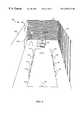
- the robot 60provides a telepresence for a user at a remote user station at a meeting in a conference room 120 .
- the conference room 120is decorated with a plain side wall 122 opposite a vertically striped side wall 124 .
- the wall 126 behind the robot 60is decorated with horizontal stripes.
- the robot 60is chairing the meeting at one end of the table 128 .
- a group of conferees 130are sifting at the sides and end of the table 128 .
- the display 84 of the robot 60displays the user's image 102 in front of the image 132 of a portion of the back wall 126 . Therefore, the three dimensional display with the image of the user's head in front of the local background enhances the user's presence in the meeting because the user appears to be in the room with the conferees 130 .
- the robot 60has a camera array 82 with side and rear cameras 106 - 114 , the video information transmitted to the remote user will include the image of the conferee 134 leaving the meeting. In this way, the robot 60 will keep the remote user informed of events in the room, just like the user was in the conference room 120 .
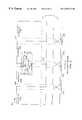
- FIGS. 5A-5Cillustrate the robot's display 84 with a texture map of front and profile views of the user's head onto the display 84 .
- a texture mapis the application of a bit map onto a three dimensional shape to give the impression of perspective and different surfaces.
- the robot 60provides a three dimensional representation of the user.
- the robot's display 84has three panels 142 , 144 , 146 that display the front view 102 , profile view 148 and other profile view 150 , respectively, of the user.
- the front view 102 of the useris displayed as a texture map over an image 152 of the wall 126 (FIG. 4) behind the robot 60 (FIG. 4 ).
- the profile view 148 of the useris displayed as a texture map over an image 154 of the wall 124 (FIG. 4) at one side of the robot 60 (FIG. 4 ).
- the other profile view 150 of the useris displayed as a texture map over an image 156 of the wall 126 (FIG. 4) at the other side of the robot 60 (FIG. 4 ).
- a flowchartillustrates a method of transmitting and displaying video information of the user's head using a pre-compression technique.
- Steps 162 - 168form a pre-compression_gather_user_image procedure which is executed by the CPU at the user station.
- Steps 170 - 176form a pre-compression_display_user_image procedure which is executed by the CPU on the robot.
- step 162at least one video image of the user is received.
- a chroma-key blue or green backgroundis behind the user to make the user's image easier to identify from the background.
- step 164a bounding box in the video image containing information about the user's head is identified.
- a bounding boxis the smallest rectangular box surrounding an object that is aligned to the x and y axes of the display.
- the video image data in the bounding boxis compressed.
- the user stationtransmits the compressed video image data in the bounding box to the robot.
- the pre-compression_gather_user_image procedure and pre-compression_display_user_image procedureis executed for the display of the front and profile views of the user.
- the pre-compression_display_user_image procedureimplementing steps 170 - 176 , is executed at the robot.
- the video image datais received and decompressed.
- the robotidentifies a background image substantially opposite the display of the user's image.
- the background imageis displayed on the robot.
- the background imageis warped to match a viewer's perspective.
- warpedmeans a geometric transformation of an image. In this case, warping is used to render the background image from a different perspective.
- the robotscales and translates a texture map of the user's head to fill the display with the user's image in the foreground.
- a flowchartillustrates a method of transmitting and displaying video information of the user's head using a post-compression technique.
- Steps 182 - 186form a postcompression_gather_user_image procedure that is executed by the CPU at the user station.
- a video image of the useris received. As described above, the user is in front of a chroma key blue or green background.
- the video image data received from the camerais compressed. Unlike the method of FIG. 6, the user station does not identify the bounding box with the user's image.
- the compressed video image datais transmitted to the robot.
- steps 188 - 196form a post-compression_display_user_image procedure that is executed by the CPU at the robot.
- the video image datais received and decompressed.
- a bounding box in the video image data that contains information about the user's headis identified.
- a background image opposite the display of the user's imageis identified and acquired.
- the background imageis displayed.
- the robotscales and translates a texture map of the user's head to fill the display with the user's image in the foreground.
- the user at the user stationis provided with foveal video.
- Foveal videosimulates the natural view seen by the human eye.
- light receptorsare not uniformly distributed but concentrated in a portion of the eye called the fovea.
- the foveais the part of the eye that is used when we look directly at an object point.
- the large number of light receptors in the foveaallow humans to see details when looking directly at objects.
- the light receptors outside the foveado not provide as high image definition, the light receptors outside the fovea do provide the function of detecting motion and differences in the amount of light, thereby signaling viewers to change their gaze in an appropriate direction for a more detailed examination of the surroundings using the fovea.
- a high resolution image 202 and one or more low resolution images 204 , 206are combined to produce a single image, partially high resolution, partially low resolution, on the display 70 at the user station.
- the high resolution image 202at least partially overlaps at least one of the low resolution images 204 , 206 .
- Dashed lines 208 , 210illustrate the overlap regions. In this way, the resolution of a particular area of interest 202 in the received image is increased while providing the user with a peripheral low resolution view 204 , 206 of the surrounding area.
- the high resolution image 202is combined with two low resolution images 204 , 206 .
- the camera array 82 of FIGS. 3A and 3Bprovides the high and low resolution images for foveal video.
- the high resolution camera 104provides the video information for the high resolution image 202
- the low resolution cameras 106 , 110provide the video information for the low resolution images 204 , 206 , respectively.
- Foveal videois especially useful when the robot needs to “read” information, such as room numbers in a hallway.
- the exemplary number “123” in the high resolution region 202is much easier to read than the exemplary number “124” in the low resolution region 204 .
- FIG. 8Aillustrates a high resolution image 202 substantially centered between the two low resolution images 204 , 206 .
- FIG. 8Ashows region boundaries 212 , 214 in the overlap regions 208 , 210 , in practice, a single seamless image without lines is generated and displayed.
- the overlap regions 208 , 210are formed because the video image data from the high and low resolution cameras have overlapping views.
- the cameras on the robotare aligned to provide a predetermined amount of overlap. Each camera captures one aspect of the image and the digital information from each camera is transmitted separately.
- the computer system at the user stationexecutes a foveal_video procedure that uses the digital information in the overlap region to align and blend the images.
- FIG. 8Billustrates a preferred implementation of foveal video.
- two low resolution images 222 , 224are blended together in the center of a display.
- a portion of the low resolution images 222 , 224is “cut-out” leaving a small overlap region, shown by the dashed lines, that overlaps the high resolution image 226 .
- the high resolution image 226is aligned and blended with the low resolution images 222 , 224 in the overlap regions.
- the low resolution images 228 , 229are aligned and blended with low resolution images 222 , 224 , respectively.
- the high resolution image 226is vertically positioned in about the upper two-thirds portion of the display 70 and horizontally positioned in substantially the center of the display surrounded by the low resolution images.
- the human foveahas a field of view of approximately three degrees, while human peripheral vision has a field of view of approximately 150°.
- the field of view of the high resolution areais typically twenty-five to thirty-five degrees. Because the fovea of the human eye covers about three degrees, using the present invention, a user may not need to turn their head as much to read detailed information. However, in the high resolution portion, the present invention does not show as much detail as the human eye: the resolution of the human fovea is about one arc minute while the invention provides about six arc minutes in the high resolution portion.
- FIG. 8Cillustrates multiple levels of foveal video that is used with a low, medium and high resolution cameras focused on the same object.
- a sixteen millimeter (mm) telephoto lens, an eight mm telephoto lens and a four mm wide angle lensare all focused on the same object.
- the resulting imagesare displayed in a series of concentric rectangles. The edges of the rectangles are aligned and blended to provide a seamless image.
- the medium resolution imagehas a pixel density that is at least two times the pixel density of the low resolution images; and the high resolution image has a pixel density at least two times the pixel density of the medium resolution image.
- the pixel densityincreases by a factor of two at each level of foveal video.
- FIG. 9is a flowchart of a method of displaying images using foveal video in a seamless display that is implemented in the foveal_video procedure.
- a first image of high resolution image informationis displayed in a first portion of the single view on the display.
- at least one low resolution imageis combined with the first image to produce a single image on the display.
- the high resolution imageat least partially overlaps at least one low resolution image.
- FIG. 10is a detailed flowchart of the method of FIG. 9 .
- step 254a high resolution image and at least one low resolution image are received.
- step 256the high resolution and low resolution images are corrected for lens imperfections which will be discussed in detail below.
- step 258the high resolution image is scaled to the same scale as at least one of the low resolution images.
- step 260a predetermined portion of at least one of the low resolution images that corresponds to the high resolution image is cut out to leave an overlapping edge region for blending. In this way, the detailed image information in the high resolution image is preserved by not blending it with the low resolution image.
- step 262the high resolution image is aligned with at least one of the low resolution images.
- step 264the edges of the high resolution image are blended with at least one of the displayed low resolution images to provide a seamless combined image.
- step 266the combined seamless image is displayed.
- step 268a portion of the single image is magnified. In this step, the user can select the portion of the image to magnify and the amount of magnification.
- FIG. 11illustrates an alternate method of displaying images using foveal video that displays a border around the high resolution image.
- Steps 254 - 264are executed as described above and are not shown.
- step 270a border that surrounds the high resolution image in the seamless combined image is generated.
- step 266displays the combined image with the border.
- the blending of step 264is not performed because the overlapping region is covered with the border.
- FIG. 12illustrates an intensity map used for blending images of a display 70 .
- low resolution images 222 a and 222 bhave an overlap region 208 .
- Low resolution images 224 a and 224 balso have an overlap region 210 .
- Another overlap region 272is formed between low resolution regions 222 a and 224 a .
- An intensity map for blending the images in the overlap regionsis shown for cut line 274 . If the intensity values for each pixel in the overlap regions were added, the overlap regions would appear brighter than the non-overlapping regions on the display.
- the intensity mapshows how the intensity values from each image are weighted before they are summed.
- the percentage of the intensity value from region 222 bis linearly reduced until the percentage reaches zero at the other end of the overlap region 208 .
- the percentage of the intensity values from region 222 alinearly increases from zero to one hundred percent in the overlap region.
- the blendingcan be represented by the formula:
- I Ais the pixel intensity from region A (for example, region 222 b ),
- I Bis the pixel intensity from region B (for example, region 222 a ), and
- the transparency factorsvary linearly from one to zero, and from zero to one, in the overlap region.
- Transparency factor Bis equal to one minus the value of transparency factor A.
- the high resolution region 226overlays portions of the low resolution regions 222 a , 224 a and would appear to be a complete overlap region.
- the high and low resolution camerasare precisely aligned and their corresponding images will be similarly aligned.
- predetermined “cut-out” regions 222 c , 224 care identified as shown by dashed lines 222 d and 224 d .
- the low resolution image data in the “cut-out” regions 222 c , 224 cis not blended with the overlapping high resolution image data in the “cut-out” regions 222 c , 224 c thereby preserving and displaying the high resolution image information.
- a border region of the high and low resolution regionsoverlaps at the edges of the “cut-out” regions 222 c , 224 c and the high resolution region 226 .
- the edges of the high resolution imageare aligned to and blended with the edges of the “cut-out” regions in the overlap region; while the high resolution image information is displayed inside the “cut-out” region to provide a seamless display.
- peripheral visionthe human eye can detect movement and distinguish between light and dark even at seventy-five degrees with respect to the eye's optic axis.
- a user at a user stationdoes not have the benefit of their peripheral vision.
- Anamorphic videoprovides this peripheral visual information to the user.
- box 302represents a first band of the image.
- the first band of the imageis a high resolution image.
- Boxes 304 - 310represent other portions of the image. In an alternate embodiment, these other portions of the image are from at least one wide angle low resolution camera. Note that the first band has a narrower horizontal field of view than the other bands.
- the image information for the first bandis mapped to region 312 of the display 300 .
- the image information for the adjacent band 304is displayed in region 314 of the display 300 and the image information for the next adjacent band 306 is displayed in region 316 of the display 300 .
- regions 312 , 314 and 318have the same width, while regions 316 and 320 have half the width of regions 312 , 314 and 318 .
- the image shown in region 302is considered to have the same ratio of width to height as region 312 of the display; and therefore has a scale of “1X” between the image information in band 302 and the region 312 of the display.
- band 304is twice as wide as band 302 ; therefore, band 304 is scaled, relative to region 312 , to display all the image information in region 314 .
- the image information in band 304is horizontally scaled by a factor of two, as indicated by the designation “2X,” for display.
- Region 316 on the display 300is half the size of region 314 ; therefore, the image information in band 306 is scaled by a factor of four, as indicated by the designation “4X,” for display.
- boundaries between regionsare shown as lines 322 , 324 , 326 and 328 . In a preferred implementation, the boundary lines are not displayed.
- the images 302 - 310may have overlapping regions which are aligned and blended together.
- the bandsmay be digitally corrected for lens imperfections and camera artifacts. If multiple cameras are used to generate each or subsets of the bands, the bands may be digitally aligned, blended, scaled and displayed using anamorphic video.
- Circlesare used to depict the result of the anamorphic video scaling described above.
- Each of the views 302 , 304 , 306 from the camerashas a circle 332 , 334 , 336 , respectively.
- region 312has a horizontal scale of “1X” and the displayed circle 342 is round.
- region 314which has a horizontal scale of “2X”
- the horizontal dimension of the circle 334is reduced by half and the displayed circle 344 appears as an oval.
- region 316the horizontal dimension of the circle 336 is reduced by a factor of four to display an oval 346 .
- a circle 347is partially within a region 312 and the next adjacent region 314 , note that at the boundary 322 the horizontal scaling abruptly changes so that the portion of the circle within region 312 is displayed at the “1X” scale, while the portion of the circle in region 314 is displayed at the “2X” scale. Similarly, the portion of a circle 348 in region 314 is displayed at the “2X” scale, while the portion of the circle 348 in region 316 is displayed at the “4X” scale.
- the size of each region of the displaycan be adjusted by the user.
- the useruses a mouse to click on the boundary 322 - 328 to select and reposition the boundary 322 - 328 .
- the useris provided with a ruler bar 339 to set the size of each region 312 - 320 .
- an exemplary display 350illustrates visually abrupt anamorphic video in both the horizontal and vertical dimensions. Except for orientation, the image information in the vertical dimension is displayed in the same manner as the horizontal dimension described above.
- the vertical dimensioncan be used to provide a view of at least a portion of the ceiling and floor, while the horizontal view can provide a sideways view of walls.
- FIG. 15is a flowchart of the method of displaying an image using visually abrupt anamorphic video.
- a center portion of an imageis displayed on a display at a first scale.
- first and second side portions of the imageare displayed adjacent the center portion. The first and second side portions are displayed at a second scale higher than the first scale.
- a top portion and a bottom portion of the imageare displayed on the display.
- the top and bottom portionsare adjacent the center portion, the top and bottom portions being displayed at a third scale higher than the first scale.
- FIG. 16depicts a flowchart for displaying an image 400 using graduated anamorphic video
- FIG. 17depicts a display 401 using graduated anamorphic video.
- the image 400has three views 402 , 404 , 406 .
- the center view 402 of the image 400is displayed at a first scale (1X) in region 410 of the display 401 .
- the first and second side views 404 , 406 of the image 400are displayed in side portions 412 , 414 on the display 401 .
- the first and second side portions 412 , 414are adjacent the center portion 408 at first and second inner edges, 416 , 418 , respectively.
- the first and second side portions 412 , 414have first and second outer edges, 420 , 422 , respectively.
- the first and second side portions 412 , 414are displayed at an increasing scale such that the first and second side portions 412 , 414 are displayed at a second scale equal to a minimum predetermined scale at the first and second inner edges 416 , 418 .
- the second scaleis increased to a maximum predetermined scale at the first and second outer edges 420 , 422 .
- the second scaleis geometrically increased from the minimum predetermined scale to the maximum predetermined scale as a function of image position.
- the second scaleis linearly increased from the minimum predetermined scale to the maximum predetermined scale as a function of image position.
- the second scaleis increased from the minimum predetermined scale to the maximum predetermined scale using a predetermined weighting function.
- the predetermined weighting functionincludes the following: a linear function, an exponential function, or a non-linear function.
- the linear functionscales the image by a constant such as 1.5.
- the exponential function, such as x Nscales the image at an increasing scale as a function of image position, such that the highest scaling takes place at the outer edges of the image.
- Nis equal to 1.5.
- a non-linear functionvaries the amount of scaling in the side portions of the image such that a particular area has a reduced scale and is surrounded by areas having a higher scale.
- FIG. 18is a diagram of a display using the concept of graduated anamorphic video in both a horizontal and vertical dimension, 426 , 428 , respectively.
- FIG. 18shows an embodiment that displays boundaries 416 , 418 , 432 , 434 , in a preferred embodiment a seamless display of the image without boundaries is displayed.
- the horizontal dimensionmay use a different weighting function from vertical dimension.
- the usercan graphically select boundaries using a ruler and choose the scale for portions of the display.
- the display 300can use both abrupt and graduated anamorphic video.
- the image information in inner regions 312 , 314 and 318is displayed using abrupt anamorphic video
- the image information in outer regions 316 and 320is displayed using graduated anamorphic video.
- the low and high resolution imagesare combined into a seamless image as described above.
- the high resolution image in region 452is displayed using foveal video and also at a 1X scale in both the horizontal and vertical dimensions, using anamorphic video.
- the edges 458 , 460 of the high resolution regionare identified.
- the low resolution image information between the edges 458 , 460 in region 462is displayed at same scale as the high resolution region 452 .
- the image information in the low resolution regions 464 , 466 that is outside region 462is displayed using either abrupt or graduated anamorphic video as described above.
- foveal videois combined with anamorphic video in both the horizontal and vertical dimensions.
- the description for combining foveal video with anamorphic video in the horizontal dimensionapplies to combining foveal video with anamorphic video in the vertical dimension.
- the high resolution viewis not scaled and is displayed inside the center portion of the image.
- the high resolution viewis scaled.
- step 470corrects for lens barrel distortion and step 472 corrects for lens light falloff.
- image 474has lens barrel distortion
- image 476shows the image without barrel distortion.
- Lens barrel distortionrounds images such that a square object will appear to have rounded sides.
- region 478the extent of the lens barrel distortion is shown by region 478 and the video information in region 478 is discarded.
- a piecewise linear approximation to the desired video edgeis performed by doing a geometric transformation on each of the triangles formed by the radial lines 480 of the image.
- FIG. 23shows the corrected image.
- a lens intensity mapshows the radial decrease in light intensity from 100% at the center to 90% at the edges.
- a black backgroundis rendered and the image is texture mapped onto an opacity map.
- the opacity maphas concentric rings of different opacity chosen to correct for lens light falloff.
- the first techniquedoes not result in final intensities of 100%, but is fast since it can be performed automatically by texture mapping hardware on a graphics card.
- a second techniquethe colors of each pixel in the video source data are multiplied by the inverse of the corresponding value in the lens intensity map of FIG. 24 .
- This second techniquerequires processing by the CPU and is slower than the first technique. However, the second technique provides final intensities up to 100%.
- an exemplary user station 50has a CPU 66 , keyboard 68 , mouse 72 , display 70 , joystick 73 , microphone 501 , and at least one speaker 502 .
- the user station 50is portable, such as a laptop computer, with a wireless network connection.
- the mouse 72is a 3-D mouse which controls the robot's arms.
- the joystick is 73is a force feedback joystick that provides the user with tactile feedback.
- the distance sensor on the robotdetects the distance of the robot from objects and the robot transmits a distance signal representing the distance.
- the user station 50increases the amount of force required to move the joystick 73 as the distance from the robot to the object decreases.
- the accelerometer on the robotsends acceleration signals indicative of motion to the CPU on the robot, which are transmitted to the user station.
- the user station 50modulates the forces output by the joystick. Therefore, if the robot is moving down a bumpy hallway, the accelerometer will detect changes in acceleration, and in response the user will “feel” the bumps.
- Two side cameras 504 , 506connect to the CPU 66 to receive images of the user's profile.
- a third camera 508receives an image with the front view of the user.
- the third camera 508is positioned and focused on the user's head to directly receive the front view of the user.
- the video image datais processed as described above with respect to FIGS. 6 and 7 and transmitted to the robot over the communication medium for display.
- the third camera 508indirectly receives the user's image.
- a partially reflective mirror 510is placed at an angle, preferably forty-five degrees, in front of the display 70 .
- the partially reflective mirror 510receives the user's image and reflects a portion of the light with the user's image up to a mirror 512 which reflects the incoming light to the third camera 508 .
- mirror 512is also at an angle of forty-five degrees.
- the partially reflective mirror 510blocks some of the light from the display 70 from reaching the user, the partially reflective mirror 510 permits a sufficient amount of light from the display 70 to reach the user without impairing the image quality that the user sees on the display 70 .
- a users imageis received 514 by the partially reflective mirror 510 which is positioned in front of the display 70 .
- a portion of the incoming light 516is reflected off the partially reflective mirror 510 to mirror 512 .
- the light 516is reflected off mirror 512 and received by the third camera 508 .
- a front view of the useris acquired in which the user appears to be looking directly into the camera 508 , and therefore directly at the remote users, while in fact the user is looking directly at the display 70 .
- a “life-size” immersion room 520functions as a user station and provides the user with a sense of being in the remote geographic location. Unlike a movie theater which is designed to present information visually for entertainment, the immersion room 520 is designed for live interaction with a robot at a remote location. The sense of presence is important for the user to be able to use the visual information to negotiate hallways, avoid obstacles and interact with others at the remote location. Therefore the types and amount of visual information needed for the robotic telepresence system distinguish the immersion room 520 from a typical movie theater.
- the immersion room 520has a screen 522 that provides the user with a 150° visual field of view.
- the angle of view of the human eyeis approximately 150°.
- the human eyecan resolve fine detail, such as text, over a small angle.
- the immersion room 520uses foveal video to provide the user with high resolution image 523 centered around an upper two-thirds vertical portion in the horizontal center of the screen 522 .
- the size of the screen 522is sufficient to allow for a “life-size” projection of the remote surroundings.
- the screen 522is six feet high. Fourth, the screen 522 is curved about the user. In one implementation, the user is positioned at or near the center point of the circular screen 522 . Fifth, because the visual field of view is 150°, the user's peripheral vision will detect peripheral motion and changes in light intensity. As stated above, the human eye can detect movement and distinguish between light and dark even at seventy-five degrees with respect to the eye's optic axis. The immersion room 520 allows the user to detect movement and distinguish between light and dark at seventy-five degrees with respect to the eye's optic axis. In addition, with anamorphic video, the peripheral information available to the user can exceed the limitations of the size of the screen. With anamorphic video, the range of visual information available to the user can exceed that of normal human vision to over 180°, and even up to 360°.
- the usersits at a console 524 that is connected to a computer system 526 in an external location 528 outside the immersion room.
- the useruses a 3-D mouse 530 , keyboard 532 and force feedback joystick 534 to control the robot in the same way as described above for the user workstation.
- the immersion room 520also has a microphone 536 and at least one speaker 538 coupled to the computer 526 to transmit the user's voice to the robot and to provide audio feedback from the microphone on the robot at the remote location.
- a projector 540is mounted on a wall above and behind the user to project a high resolution image on a center portion 523 of the screen 522 .
- Other projectors 542 , 548are positioned on the floor beneath the screen 522 and project an image onto mirrors 552 , 556 , respectively, which is reflected onto a corresponding portion of the screen 522 .
- the computer system 526receives the image data from the robot, processes the received image data and transmits that image data to the projectors for viewing.
- the methods for correcting for barrel distortion and lens light falloff, aligning the images from each of the cameras and blending the overlapping edges of the received imagesapply to the images in the immersion room. Because the projectors 542 , 548 are placed below the screen 522 on the floor, the displayed image in the immersion room 520 will be distorted by the keystone effect which will be discussed below.
- a front camera 560is disposed behind a pinhole 562 substantially in the center of the screen 522 facing the user.
- Two side cameras 562 , 564 at the sides of the screen 522capture the user's profile.
- the cameras 560 , 562 , 564connect to the computer system 526 .
- the computer systemprocesses the user's image from the cameras using the methods described above.
- rays 572 , 574define the edges of the portion of the image projected by the high resolution projector 540 onto the screen 522 .
- Rays 576 a , 576 b , 578 a , and 578 bdefine the edges of the portion of the image projected by projector 544 onto the screen 522 via mirror 552 .
- the projectors for low resolution imageshave “holes” cut out of their images for the high resolution view, as with images on a single monitor.
- Camera 560is positioned behind the pinhole in the screen 522 to receive the user's image.
- each projector 542 , 548causes each projector 542 , 548 to produce a trapezoidal image 580 , instead of a rectangular image.
- the trapezoidal image 580is brighter at the bottom than at the top.
- the uncorrected intensity at any point in the trapezoid 580is a function of the area covered by a pixel. The intensity is inversely proportional to the area covered by the pixel.
- projector 544projects an image via mirror 552 onto the screen 522 .
- Ray 592 adefines the lower edge of the image and reflects off mirror 552 as ray 592 b to define the lower edge of the image on the screen 522 .
- Ray 596 adefines the upper edge of the image and reflects off mirror 552 as ray 596 b to define the upper edge of the image on the screen 522 .
- the projected imageshould be parallel to the screen 522 .
- the keystone effectcan be digitally eliminated.
- FIG. 32is a method for correcting for the keystone effect; this method will typically be executed by a video signal processor or other digital computer apparatus.
- step 612prior to the real time execution of the video image warping procedure, a determination is made of the shape that when the trapezoid is warped, results in a rectangle.
- step 614for the low resolution images overlapped by the high resolution image, the procedure cuts out a corresponding portion of the low resolution images by not projecting light in the cut-out regions.
- the image to be projectedis warped to the determined shape.
- step 618the brightness of the image is warped to produce a projected image whose brightness distribution better matches that of the original image captured by the remote cameras.
- step 620the warped image is displayed via the low resolution projectors. In this way, the projected images will be displayed without noticeable distortion front the keystone effect and the user will be provided with a seamless image.
- FIG. 33is a diagram of the user station and the procedures implementing the methods of the present invention in memory.
- the user station 50is a computer system in which the following components connect to a system bus 620 and includes:
- a graphics card 621that connects to a display 70 ;
- a mouse 72preferably a 3-D mouse
- At least one microphone 501for sensing the user's voice to transmit to the robot
- At least one speaker 502for playing the sounds detected by the microphone on the robot;
- At least one camera 508and preferable three cameras 504 , 506 and 508 for acquiring a front view of the user, and profile views as described above;
- a disk drive 630a disk drive 630 ;
- a memory 640such as a semiconductor memory, for storing procedures.
- the procedurescan also be stored on the disk drive 630 .
- the memory 640stores an operating system 642 such as UNIXTM (trademark of UNIX System Laboratories, Inc.) and robotic telepresence procedures 646 which are executed by the processor 66 .
- the robotic telepresence procedures 646include the following:
- a connect_to_robot procedure 648that establishes a connection via the packet interface 628 and the communication medium from the robot to the user station; Alternately the connect_to_robot procedure 648 establishes the connection via modem 626 ;
- the precompression_gather_user_image procedure 650that implements the method of FIG. 6;
- the postcompression_gather_user_image procedure 652that implements the method of FIG. 7;
- a send_image procedure 654that sends the image of the user from the cameras to the robot;
- the foveal_video procedure 656that implements the methods of FIGS. 9 and 10;
- a blend_images procedure 660that blends images as described above;
- a cut_out_for_foveal procedure 662that cuts out a region in the low resolution images for displaying the high resolution image
- a display border procedure 666that displays a border around the high resolution image as shown in FIG. 11;
- An abrupt_anamorphic video procedure 668that implements the method of FIG. 15;
- a graduated_anamorphic_video procedure 670that implements the method of FIG. 16;
- a combine_foveal_anamorphic procedure 672that combines the methods of foveal and anamorphic video in a single display as described above;
- a force feedback procedure 674that increases the amount of force needed to move the joystick 73 in response to the distance sensor from the robot;
- a move_robot procedure 676that sends signals to the move the robot in response to the joystick 73 ; alternately, the signals are sent in response to the mouse 72 .
- a listen_via_robot procedure 678that receives audio signals transmitted by the robot and plays the audio signal on the speaker 502 ;
- a speak_via_robot procedure 680that receives audio signals from the user via microphone 501 and transmits the audio signals to the robot;
- a barrel_distortion_correction procedure 684that corrects for barrel distortion in the received images as discussed with respect to FIGS. 20-23;
- a lens_light_falloff procedure 686that corrects for reduction of light intensity at the edges of the lens as discussed with respect to FIGS. 20, 24 - 25 ;
- the memory 620also stores the high resolution image(s) 690 and the low resolution images 692 .
- the computer system for the immersion roomis the same as the computer system described above for the user station with the following exceptions and additions.
- Projectors 542 , 548are used in place of or, alternately, in addition to the display 70 .
- the immersion room computer systemincludes a set of projector display procedures 694 that include:
- a keystone correction procedure 698 that corrects for keystone effects as shown in FIG. 26is shown in FIG. 26 .
- the computer system on the robot 50implements the methods of the present invention in memory.
- the robot's computer systemincludes the following components that connect to a system bus 702 and includes:
- the display 84for displaying the front and profile views of the user
- a graphics card 706for processing the graphic data to display the images via the projectors 540 , 542 and 548 , and an optional display 70 ;
- the microphone 98for sensing the sounds around the robot to transmit to the user
- the speaker 96for playing the sounds detected by the microphone at the user station
- a wireless communication transmitter/receiver 76that transmits and receives signals from the wireless base station 78 ; the wireless base station 78 connects to the communication medium via a packet interface 704 such as ethernet or, alternately, a modem 706 ;
- a memory 710such as a semiconductor memory, for storing procedures and data.
- the procedures and datacan also be stored on the disk drive 708 .
- the memory 710stores an operating system 712 such as UNIX and robotic telepresence procedures 720 which are executed by the processor 80 .
- the robotic telepresence procedures 720include:
- a connect_to_user_station procedure 722that establishes the communication connection via the wireless transmitter/receiver 76 to the user station or immersion room.
- the precompression_display_user_image procedure 724that implements the method of FIG. 6;
- the postcompression_display_user_image procedure 726that implements the method of FIG. 7;
- a display_front_view procedure 728that displays the front view of the user using either the precompression_display_user_image procedure 724 or the postcompression_display_user_image procedure 726 ;
- a display_profile_view procedure 730that display the profile view of the user using either the precompression_display_user_image procedure 724 or the postcompression_display_user_image procedure 726 ;
- a send_image procedure 732that sends the images from the camera array to the user station
- a determine_distance procedure 734that receives the sensed distance information from the distance sensor 85 , determines the distance from the sensed distance information and sends the distance to the user station or immersion room;
- a send_accelerometer_data procedure 736that receive the acceleration information from the accelerometer, and sends the acceleration data to the user station or immersion room;
- a move_robot procedure 738that is responsive to the move_robot procedure at the user station that controls motor 92 and causes the robot to move;
- a turn_camera_array procedure 740that is responsive to the commands from the user station that controls motor 118 to turn the robot's head and camera array 82 ;
- a listen_to_user procedure 742that receives audio signals transmitted from the user station or immersion room and plays the audio signals on the speaker 96 ;
- a speak_to_user procedure 744that receives audio signals from the microphone 98 on the robot and transmits the audio signals to the user station or immersion room;
- a move_robot_arms procedure 746that communicates with the move_robot_arms procedure at the user station to move the robot arms 119 a , 119 b.
- the memory 710also stores high resolution images 748 and low resolution images 750 .
- each projectoris driven by a separate display computer system and the display computer systems are networked with a master computer to coordinate the displaying of the information.
- sensors other than video camerascan be used to provide the video images.
- infrared sensorsare used.
Landscapes
- Engineering & Computer Science (AREA)
- Theoretical Computer Science (AREA)
- General Engineering & Computer Science (AREA)
- Human Computer Interaction (AREA)
- Physics & Mathematics (AREA)
- General Physics & Mathematics (AREA)
- Image Processing (AREA)
Abstract
Description
The present invention relates generally to robotics, and particularly to a robotic telepresence system.
In robotic telepresence, a remotely controlled robot simulates the presence of a user. The overall experience for the user and the people interacting with the robotic telepresence device is similar to videoconferencing, except that the user has a freedom of motion and control over the robot and video input that is not present in traditional videoconferencing. The robot platform typically includes a camera, a display device, a motorized platform that includes batteries, a control computer, and a wireless computer network connection. An image of the user is displayed on the robotic telepresence device's display. This image is captured by a camera at the user's location.
In one prior art approach, a robotic device is built on a remote controlled car. However, driving the car remotely is considerably more difficult than personally walking through the same area. The robotic device uses a single small camera with a relatively small field of view and low resolution. This device shares problems with videoconferencing in that the user has “tunnel vision.” The user is not provided with a peripheral view or the environment as compared to human peripheral vision. In addition, the central resolution of the remote camera is much lower than that of the human eye, which makes it difficult to remotely read anything other than very large text.
The robotic device displays the user's image on a small LCD screen about three inches tall which does not move independently of the robotic platform. This display does not provide an appearance of eye contact between the remote user and others interacting with the remote user via the robot. The lack of eye contact makes it difficult for people to relate naturally to the person using the robotic device.
Therefore, there is a need for a method and apparatus that improves eye-contact between the remote user and others interacting with the robotic device.
A robotic telepresence system has a user station at a first geographic location and a robot at a second geographic location. The user station is responsive to a user and communicates information to and from the user. The robot is coupled to the user station and provides a three dimensional representation of the user transmitted from the user station. The robot also senses predetermined types of information and communicates the sensed information back to the user.
In this way, by providing a three dimensional representation of the user, eye contact between the user and others interacting with the robot at the remote location is improved.
Additional objects and features of the invention will be more readily apparent from the following detailed description and appended claims when taken in conjunction with the drawings, in which:
FIG. 1 is a diagram of a robotic telepresence system of the present invention.
FIG. 2 is perspective view of one embodiment of the robot of FIG.1.
FIG. 3A is a top view of the camera arrangement on the robot of FIG.2.
FIG. 3B is a top view of an alternate camera arrangement used with the robot of FIG.2.
FIG. 4 is a diagram illustrating the use of the robot of FIG. 2 in a conference room with the overlay of the user's head on a background image.
FIG. 5A is diagram of the display of the robot of FIG. 2 in the conference room of FIG. 4 illustrating the display of a texture map of a front view of user's head onto a front display.
FIG. 5B is diagram of the display of the robot of FIG. 2 in the conference room of FIG. 4 illustrating the display of the texture map of the user's side profile onto a side display.
FIG. 5C is diagram of the display of the robot of FIG. 2 in the conference room of FIG. 4 illustrating the display of the texture map of the user's other side profile onto another side display.
FIG. 6 is a flowchart illustrating a method of tracking the user's head using a pre-compression technique.
FIG. 7 is a flowchart illustrating a method of tracking the user's head using a postcompression technique.
FIG. 8A is a diagram of a display using foveal video.
FIG. 8B is a diagram of a display using foveal video in two dimensions.
FIG. 8C is a diagram of a display using multi-resolution foveal video.
FIG. 9 is a flowchart of a general method of displaying images using foveal video in a seamless display.
FIG. 10 is a flowchart of a detailed method of displaying images using foveal video in a seamless display.
FIG. 11 is a flowchart of an alternate method of displaying images using foveal video with a border identifying the high resolution image that is used with the method of FIG.9.
FIG. 12 is a diagram of a display using foveal video with an intensity map for a section of the display.
FIG. 13 is a diagram illustrating the mapping of a set of images into a display using abrupt anamorphic video.
FIG. 14 is a diagram of a display using abrupt anamorphic video in two dimensions.
FIG. 15 is a flowchart of the method of displaying an image using visually abrupt anamorphic video.
FIG. 16 is a flowchart of the method of displaying an image using graduated anamorphic video.
FIG. 17 is a diagram illustrating the mapping of a set of images on a display using graduated anamorphic video.
FIG. 18 is a diagram of a display using two-dimensional graduated anamorphic video.
FIG. 19 is a diagram of a display that combines foveal and anamorphic video in a single image.
FIG. 20 is a flowchart for additional digital imaging to be applied to received images to correct for lens barrel distortion and lens light fall off.
FIG. 21 illustrates the effect of lens barrel distortion
FIG. 22 illustrates the extent of the lens barrel distortion.
FIG. 23 is an image corrected for lens barrel distortion.
FIG. 24 is a lens intensity map for lens light falloff.
FIG. 25 is an opacity map used in a texture mapping technique for correcting for lens light falloff.
FIG. 26 is a diagram of a user station showing the camera configuration.
FIG. 27 is a diagram of the user station of FIG. 26 implemented with a partially-reflective mirror to improve eye-contact with the user.
FIG. 28 is a diagram of an immersion room.
FIG. 29 is a top down view of the immersion room showing the location of the user, projectors, cameras and mirrors.
FIG. 30 is a diagram illustrating the keystone effect.
FIG. 31 illustrates the keystone effect using a side view of one projector configuration in the immersion room of FIG.28.
FIG. 32 is a flowchart of a method for correcting for keystone effect in the display.
FIG. 33 is a diagram of the computer system of the user station and/or immersion room with procedures implementing the methods of the present invention in memory.
FIG. 34 is a diagram of the computer system of the robot with procedures implementing the methods of the present invention in memory.
In FIG. 1, arobotic telepresence system 40 has auser station 50 at a firstgeographic location 52 and arobot 60 at a secondgeographic location 62. Theuser station 50 is responsive to a user and communicates information to and receives information from the user. Therobot 60 is responsive to commands from theuser station 50 and provides a three dimensional representation of the user and audio from the user which is transmitted by theuser station 50. Therobot 60 also senses predetermined types of information and communicates the sensed information back to theuser station 50. Theuser station 50 provides an image from a camera on therobot 60, as well as audio from therobot 60.
In the embodiment shown in FIG. 1, theuser station 50 is implemented using acomputer system 64. Thecomputer system 64 has a central processing unit (CPU)66,keyboard 68,display 70,mouse 72 andjoystick 73. Thecomputer system 64 has a communications interface to acommunications medium 74. In one embodiment, thecommunications medium 74 is a public network such as the Internet. Alternately, thecommunications medium 74 includes a private network, or a combination of public and private networks.
Therobot 60 is coupled to thecommunications medium 74 via a wireless transmitter/receiver 76 on therobot 60 and at least one corresponding wireless transmitter/receiver base station 78 that is placed sufficiently near therobot 60 to transmit and receive signals as therobot 60 moves.
As shown in FIG. 2, on therobot 60, a control computer (CPU)80 is coupled to and controls acamera array 82, adisplay 84, at least onedistance sensor 85, anaccelerometer 86, the wireless computer transmitter/receiver 76, and amotorized assembly 88. Themotorized assembly 88 includes aplatform 90 with amotor 92 that is coupled towheels 94. Thecontrol computer 80 is also coupled to andcontrols speaker 96 andmicrophone 98. Theplatform 90 supports apower supply 100 including batteries for supplying power to thecontrol computer 80, themotor 92, thedisplay 84 and thecamera array 82.
An image of theuser 102 is displayed on the robot'sdisplay 84. The user's image is captured by one or more cameras at the user's location.
Therobot 60 has at least onefirst sensor 104 to sense information at a first predetermined high resolution level, and at least one second sensor106-114 to sense information at a predetermined low resolution level. In particular, in thecamera array 82, at least onehigh resolution camera 104 senses video information at a first predetermined high resolution level, and at least onelow resolution camera robot 60 to the user station50 (FIG.1). Thehigh resolution camera 104 is physically aligned with themotorized assembly 88 in a forward direction of travel. Therobot 60 transmits high resolution images to the user in a direction of travel.
Therobot 60 has a “head”115 that includes thecamera array 82 and thedisplay 84. In an alternate embodiment, thehead 115 with thecamera array 82 is mounted on ashaft 116 which is coupled to amotor 118. In response to user commands to turn thecamera array 82, thecontrol computer 80 activates themotor 118 which turns theshaft 116 with thecamera array 82. In this way the user is provided with a way of using the robot'shigh resolution camera 104 to look around. For example, if therobot 60 were traveling down a hall, the high resolution camera could be looking at one side of the hall to allow the user to read office numbers ninety degrees to the direction of travel. Thehead 115 with the cameras104-114 may also be tilted up and down to aid in viewing objects above or below the robot. In addition, when thehead 115 moves, thedisplay 84 also moves and enhances the sense of presence of the user at the remote location.
Thedistance sensor 85 is an ultrasonic device that sends signals indicating the distance of therobot 60 from objects. Theaccelerometer 86 provides signals indicative of motion of the robot caused by increasing or decreasing speed, turning left or right, or even by vibrations from a bumpy surface.
Therobot 60 also has right and leftarms camera array 82 that are also coupled to theCPU 80. Thearms arms camera array 82. To prevent injury to people, therobot arms arms
In FIG. 3A, in thecamera array 82, thehigh resolution camera 104 is opposite a low resolutionrear camera 114. In a preferred embodiment, thehigh resolution camera 104 uses a telephoto lens, while the low resolution cameras106-114 use wide angle lenses. As will be described in detail below, the low resolutionrear camera 114 provides background information for the robot's display. In an alternate embodiment, the video image from thelow resolution camera 114 is transmitted to the user station so the user can see events outside the normal human visual range.
The two lowresolution side cameras cameras low resolution cameras high resolution camera 104 and theside cameras
In FIG. 3B, an alternate embodiment of thecamera array 82 is the same as shown in FIG. 3A except that two pairs oflow resolution cameras cameras low resolution cameras
Although the invention will be described with respect to thecamera array 82 of FIG. 3A, the camera array of FIG. 3B is used in an alternate embodiment.
As shown in FIG. 4, therobot 60 provides a telepresence for a user at a remote user station at a meeting in aconference room 120. Theconference room 120 is decorated with aplain side wall 122 opposite a verticallystriped side wall 124. At the end of theconference room 120, thewall 126 behind therobot 60 is decorated with horizontal stripes. Therobot 60 is chairing the meeting at one end of the table128. A group ofconferees 130 are sifting at the sides and end of the table128. Note that thedisplay 84 of therobot 60 displays the user'simage 102 in front of theimage 132 of a portion of theback wall 126. Therefore, the three dimensional display with the image of the user's head in front of the local background enhances the user's presence in the meeting because the user appears to be in the room with theconferees 130.
Note that one of theconferees 134 is leaving the meeting by walking behind the robot to thedoor 128. Because therobot 60 has acamera array 82 with side and rear cameras106-114, the video information transmitted to the remote user will include the image of theconferee 134 leaving the meeting. In this way, therobot 60 will keep the remote user informed of events in the room, just like the user was in theconference room 120.
FIGS. 5A-5C illustrate the robot'sdisplay 84 with a texture map of front and profile views of the user's head onto thedisplay 84. A texture map is the application of a bit map onto a three dimensional shape to give the impression of perspective and different surfaces. Note that therobot 60 provides a three dimensional representation of the user. The robot'sdisplay 84 has threepanels front view 102,profile view 148 andother profile view 150, respectively, of the user. In FIG. 5A, thefront view 102 of the user is displayed as a texture map over animage 152 of the wall126 (FIG. 4) behind the robot60 (FIG.4). In FIG. 5B, theprofile view 148 of the user is displayed as a texture map over animage 154 of the wall124 (FIG. 4) at one side of the robot60 (FIG.4). In FIG. 5C, theother profile view 150 of the user is displayed as a texture map over animage 156 of the wall126 (FIG. 4) at the other side of the robot60 (FIG.4).
In FIG. 6, a flowchart illustrates a method of transmitting and displaying video information of the user's head using a pre-compression technique. Steps162-168 form a pre-compression_gather_user_image procedure which is executed by the CPU at the user station. Steps170-176 form a pre-compression_display_user_image procedure which is executed by the CPU on the robot. Instep 162, at least one video image of the user is received. A chroma-key blue or green background is behind the user to make the user's image easier to identify from the background. Instep 164, a bounding box in the video image containing information about the user's head is identified. A bounding box is the smallest rectangular box surrounding an object that is aligned to the x and y axes of the display. Instep 166, the video image data in the bounding box is compressed. Instep 168, the user station transmits the compressed video image data in the bounding box to the robot. The pre-compression_gather_user_image procedure and pre-compression_display_user_image procedure is executed for the display of the front and profile views of the user.
The pre-compression_display_user_image procedure, implementing steps170-176, is executed at the robot. Instep 170, the video image data is received and decompressed. Instep 172, the robot identifies a background image substantially opposite the display of the user's image. Instep 174, the background image is displayed on the robot. In an alternate embodiment, the background image is warped to match a viewer's perspective. In this description, warped means a geometric transformation of an image. In this case, warping is used to render the background image from a different perspective. Instep 176, the robot scales and translates a texture map of the user's head to fill the display with the user's image in the foreground.
In FIG. 7, a flowchart illustrates a method of transmitting and displaying video information of the user's head using a post-compression technique. Steps182-186 form a postcompression_gather_user_image procedure that is executed by the CPU at the user station. Instep 182, a video image of the user is received. As described above, the user is in front of a chroma key blue or green background. Instep 184, the video image data received from the camera is compressed. Unlike the method of FIG. 6, the user station does not identify the bounding box with the user's image. Instep 186, the compressed video image data is transmitted to the robot.
At the robot, steps188-196 form a post-compression_display_user_image procedure that is executed by the CPU at the robot. In step188, the video image data is received and decompressed. Instep 190, a bounding box in the video image data that contains information about the user's head is identified. Instep 192, a background image opposite the display of the user's image is identified and acquired. Instep 194, the background image is displayed. Instep 196, the robot scales and translates a texture map of the user's head to fill the display with the user's image in the foreground.
In a particularly significant aspect of the invention shown in FIG. 8A, the user at the user station is provided with foveal video. Foveal video simulates the natural view seen by the human eye. In the human eye, light receptors are not uniformly distributed but concentrated in a portion of the eye called the fovea. The fovea is the part of the eye that is used when we look directly at an object point. The large number of light receptors in the fovea allow humans to see details when looking directly at objects. Although the light receptors outside the fovea do not provide as high image definition, the light receptors outside the fovea do provide the function of detecting motion and differences in the amount of light, thereby signaling viewers to change their gaze in an appropriate direction for a more detailed examination of the surroundings using the fovea.
As shown in FIG. 8A, in foveal video, ahigh resolution image 202 and one or morelow resolution images display 70 at the user station. Thehigh resolution image 202 at least partially overlaps at least one of thelow resolution images lines interest 202 in the received image is increased while providing the user with a peripherallow resolution view high resolution image 202 is combined with twolow resolution images
Thecamera array 82 of FIGS. 3A and 3B provides the high and low resolution images for foveal video. Thehigh resolution camera 104 provides the video information for thehigh resolution image 202, while thelow resolution cameras low resolution images
Foveal video is especially useful when the robot needs to “read” information, such as room numbers in a hallway. For example, the exemplary number “123” in thehigh resolution region 202 is much easier to read than the exemplary number “124” in thelow resolution region 204.
In particular, FIG. 8A illustrates ahigh resolution image 202 substantially centered between the twolow resolution images region boundaries overlap regions overlap regions
FIG. 8B illustrates a preferred implementation of foveal video. In this embodiment, twolow resolution images low resolution images high resolution image 226. Thehigh resolution image 226 is aligned and blended with thelow resolution images low resolution images low resolution images
Preferably, thehigh resolution image 226 is vertically positioned in about the upper two-thirds portion of thedisplay 70 and horizontally positioned in substantially the center of the display surrounded by the low resolution images.
The human fovea has a field of view of approximately three degrees, while human peripheral vision has a field of view of approximately 150°. In the invention, the field of view of the high resolution area is typically twenty-five to thirty-five degrees. Because the fovea of the human eye covers about three degrees, using the present invention, a user may not need to turn their head as much to read detailed information. However, in the high resolution portion, the present invention does not show as much detail as the human eye: the resolution of the human fovea is about one arc minute while the invention provides about six arc minutes in the high resolution portion.
FIG. 8C illustrates multiple levels of foveal video that is used with a low, medium and high resolution cameras focused on the same object. In one embodiment, a sixteen millimeter (mm) telephoto lens, an eight mm telephoto lens and a four mm wide angle lens are all focused on the same object. The resulting images are displayed in a series of concentric rectangles. The edges of the rectangles are aligned and blended to provide a seamless image. For example, the medium resolution image has a pixel density that is at least two times the pixel density of the low resolution images; and the high resolution image has a pixel density at least two times the pixel density of the medium resolution image. In other words, the pixel density increases by a factor of two at each level of foveal video.
FIG. 9 is a flowchart of a method of displaying images using foveal video in a seamless display that is implemented in the foveal_video procedure. Instep 250, a first image of high resolution image information is displayed in a first portion of the single view on the display. Instep 252, at least one low resolution image is combined with the first image to produce a single image on the display. The high resolution image at least partially overlaps at least one low resolution image.
FIG. 10 is a detailed flowchart of the method of FIG.9. Instep 254, a high resolution image and at least one low resolution image are received. Instep 256, the high resolution and low resolution images are corrected for lens imperfections which will be discussed in detail below. Instep 258, the high resolution image is scaled to the same scale as at least one of the low resolution images. Instep 260, a predetermined portion of at least one of the low resolution images that corresponds to the high resolution image is cut out to leave an overlapping edge region for blending. In this way, the detailed image information in the high resolution image is preserved by not blending it with the low resolution image. Instep 262, the high resolution image is aligned with at least one of the low resolution images. Instep 264, the edges of the high resolution image are blended with at least one of the displayed low resolution images to provide a seamless combined image. Instep 266, the combined seamless image is displayed. Inoptional step 268, a portion of the single image is magnified. In this step, the user can select the portion of the image to magnify and the amount of magnification.
FIG. 11 illustrates an alternate method of displaying images using foveal video that displays a border around the high resolution image. Steps254-264 are executed as described above and are not shown. Afterstep 264 is executed, instep 270, a border that surrounds the high resolution image in the seamless combined image is generated. Then, step266 displays the combined image with the border. In an alternate embodiment, the blending ofstep 264 is not performed because the overlapping region is covered with the border.
FIG. 12 illustrates an intensity map used for blending images of adisplay 70. In thisdisplay 70,low resolution images overlap region 208.Low resolution images overlap region 210. Anotheroverlap region 272 is formed betweenlow resolution regions low resolution region 222b, one hundred percent of the intensity value for the pixels ofregion 222bis used until theoverlap region 208 is reached. In the overlap region, the percentage of the intensity value fromregion 222bis linearly reduced until the percentage reaches zero at the other end of theoverlap region 208. Simultaneously, the percentage of the intensity values fromregion 222alinearly increases from zero to one hundred percent in the overlap region. The blending can be represented by the formula:
where:
IA is the pixel intensity from region A (for example,region 222b),
IB is the pixel intensity from region B (for example,region 222a), and
the transparency factors vary linearly from one to zero, and from zero to one, in the overlap region.
A transparency factor of one hundred percent completely overlays one image on another, while a transparency factor of zero eliminates a region from being displayed. At the center of the overlap region, a transparency factor of fifty percent is applied to each image. Transparency factor B is equal to one minus the value of transparency factor A.
In thedisplay 70 of FIG. 12, thehigh resolution region 226 overlays portions of thelow resolution regions regions lines regions regions regions high resolution region 226. The edges of the high resolution image are aligned to and blended with the edges of the “cut-out” regions in the overlap region; while the high resolution image information is displayed inside the “cut-out” region to provide a seamless display.
Using peripheral vision, the human eye can detect movement and distinguish between light and dark even at seventy-five degrees with respect to the eye's optic axis. A user at a user station does not have the benefit of their peripheral vision. Anamorphic video provides this peripheral visual information to the user.
In addition, if all the video information from the camera array were displayed on a typical display for a computer system such as a liquid crystal display (LCD) or a cathode ray tube (CRT), the amount of video information displayed would need to be greatly scaled down to fit on the display and details would be lost. In addition, only certain portions of the display may be of particular interest. Anamorphic video provides users with a way to have detailed information in a particular region of interest while expanding their field of view to include all or a portion of the information from the cameras of the camera array.
In FIG. 13, five bands or portions of an image are mapped to adisplay 300. All five bands can be from one camera with a wide angle lens or from multiple cameras.Box 302 represents a first band of the image. In one embodiment, the first band of the image is a high resolution image. Boxes304-310 represent other portions of the image. In an alternate embodiment, these other portions of the image are from at least one wide angle low resolution camera. Note that the first band has a narrower horizontal field of view than the other bands. The image information for the first band is mapped toregion 312 of thedisplay 300. The image information for theadjacent band 304 is displayed inregion 314 of thedisplay 300 and the image information for the nextadjacent band 306 is displayed inregion 316 of thedisplay 300.
In theexemplary display 300,regions regions regions region 302 is considered to have the same ratio of width to height asregion 312 of the display; and therefore has a scale of “1X” between the image information inband 302 and theregion 312 of the display. However,band 304 is twice as wide asband 302; therefore,band 304 is scaled, relative toregion 312, to display all the image information inregion 314. In this example, the image information inband 304 is horizontally scaled by a factor of two, as indicated by the designation “2X,” for display.Region 316 on thedisplay 300 is half the size ofregion 314; therefore, the image information inband 306 is scaled by a factor of four, as indicated by the designation “4X,” for display. In one embodiment, boundaries between regions are shown aslines
Circles are used to depict the result of the anamorphic video scaling described above. Each of theviews circle display 300,region 312 has a horizontal scale of “1X” and the displayedcircle 342 is round. Inregion 314 which has a horizontal scale of “2X,” the horizontal dimension of thecircle 334 is reduced by half and the displayedcircle 344 appears as an oval. Inregion 316, the horizontal dimension of thecircle 336 is reduced by a factor of four to display an oval346. If acircle 347 is partially within aregion 312 and the nextadjacent region 314, note that at theboundary 322 the horizontal scaling abruptly changes so that the portion of the circle withinregion 312 is displayed at the “1X” scale, while the portion of the circle inregion 314 is displayed at the “2X” scale. Similarly, the portion of acircle 348 inregion 314 is displayed at the “2X” scale, while the portion of thecircle 348 inregion 316 is displayed at the “4X” scale.
On thedisplay 300, the size of each region of the display can be adjusted by the user. For example, to adjust the size of the regions312-320 on the display, the user uses a mouse to click on the boundary322-328 to select and reposition the boundary322-328. In another embodiment, the user is provided with aruler bar 339 to set the size of each region312-320.
In FIG. 14, anexemplary display 350 illustrates visually abrupt anamorphic video in both the horizontal and vertical dimensions. Except for orientation, the image information in the vertical dimension is displayed in the same manner as the horizontal dimension described above. For example, the vertical dimension can be used to provide a view of at least a portion of the ceiling and floor, while the horizontal view can provide a sideways view of walls.
FIG. 15 is a flowchart of the method of displaying an image using visually abrupt anamorphic video. Instep 382, a center portion of an image is displayed on a display at a first scale. Instep 384, first and second side portions of the image are displayed adjacent the center portion. The first and second side portions are displayed at a second scale higher than the first scale.
For anamorphic video in the horizontal and vertical directions, instep 386, a top portion and a bottom portion of the image are displayed on the display. The top and bottom portions are adjacent the center portion, the top and bottom portions being displayed at a third scale higher than the first scale.
FIG. 16 depicts a flowchart for displaying animage 400 using graduated anamorphic video, while FIG. 17 depicts adisplay 401 using graduated anamorphic video. Referring to both FIGS. 16 and 17, theimage 400 has threeviews step 408, thecenter view 402 of theimage 400 is displayed at a first scale (1X) inregion 410 of thedisplay 401. In step411, the first andsecond side views image 400 are displayed inside portions display 401. The first andsecond side portions center portion 408 at first and second inner edges,416,418, respectively. The first andsecond side portions second side portions second side portions inner edges outer edges
In one embodiment, the second scale is geometrically increased from the minimum predetermined scale to the maximum predetermined scale as a function of image position. In an alternate embodiment, the second scale is linearly increased from the minimum predetermined scale to the maximum predetermined scale as a function of image position. In yet another alternate embodiment, the second scale is increased from the minimum predetermined scale to the maximum predetermined scale using a predetermined weighting function. For example, the predetermined weighting function includes the following: a linear function, an exponential function, or a non-linear function. The linear function scales the image by a constant such as 1.5. The exponential function, such as xNscales the image at an increasing scale as a function of image position, such that the highest scaling takes place at the outer edges of the image. In one embodiment, N is equal to 1.5. A non-linear function varies the amount of scaling in the side portions of the image such that a particular area has a reduced scale and is surrounded by areas having a higher scale.
FIG. 18 is a diagram of a display using the concept of graduated anamorphic video in both a horizontal and vertical dimension,426,428, respectively. Although FIG. 18 shows an embodiment that displaysboundaries
In another embodiment, the user can graphically select boundaries using a ruler and choose the scale for portions of the display.
Referring back to FIG. 13, thedisplay 300 can use both abrupt and graduated anamorphic video. For example, the image information ininner regions outer regions
Referring now to FIG. 19, foveal and anamorphic video are combined in a single image. The low and high resolution images are combined into a seamless image as described above. The high resolution image inregion 452 is displayed using foveal video and also at a 1X scale in both the horizontal and vertical dimensions, using anamorphic video. To combine thishigh resolution region 452 with thelow resolution regions edges edges region 462 is displayed at same scale as thehigh resolution region 452. The image information in thelow resolution regions outside region 462 is displayed using either abrupt or graduated anamorphic video as described above.
In another embodiment, foveal video is combined with anamorphic video in both the horizontal and vertical dimensions. The description for combining foveal video with anamorphic video in the horizontal dimension applies to combining foveal video with anamorphic video in the vertical dimension.
Preferably, the high resolution view is not scaled and is displayed inside the center portion of the image. In an alternate embodiment, the high resolution view is scaled.
As mentioned above, with respect to step256 of FIG. 10, additional digital imaging is performed to correct for lens imperfections. In FIG. 20,step 470 corrects for lens barrel distortion and step472 corrects for lens light falloff.
In FIG. 21,image 474 has lens barrel distortion, whileimage 476 shows the image without barrel distortion. Lens barrel distortion rounds images such that a square object will appear to have rounded sides. In FIG. 22, the extent of the lens barrel distortion is shown byregion 478 and the video information inregion 478 is discarded. To correct for the distortion, a piecewise linear approximation to the desired video edge is performed by doing a geometric transformation on each of the triangles formed by theradial lines 480 of the image. FIG. 23 shows the corrected image.
With inexpensive lenses, images tend to be brighter at the center and dimmer at the edges. In FIG. 24, a lens intensity map shows the radial decrease in light intensity from 100% at the center to 90% at the edges. To correct lens light falloff, one of the following two techniques is used. In a first technique, a black background is rendered and the image is texture mapped onto an opacity map. As shown in FIG. 25, the opacity map has concentric rings of different opacity chosen to correct for lens light falloff. The first technique does not result in final intensities of 100%, but is fast since it can be performed automatically by texture mapping hardware on a graphics card.
In a second technique, the colors of each pixel in the video source data are multiplied by the inverse of the corresponding value in the lens intensity map of FIG.24. This second technique requires processing by the CPU and is slower than the first technique. However, the second technique provides final intensities up to 100%.
These digital imaging techniques to correct for distortion and light falloff caused by lens imperfections are done at the user station after the image is received from the robot. Alternately, the corrections for lens barrel distortion and lens light falloff are done at the robot prior to transmitting the image. In another alternate embodiment, these digital imaging techniques to correct for lens imperfections are performed on the user's image at the user station prior to transmitting the user's image to the robot.
In FIG. 26, anexemplary user station 50 has aCPU 66,keyboard 68,mouse 72,display 70,joystick 73,microphone 501, and at least onespeaker 502. In an alternate embodiment, theuser station 50 is portable, such as a laptop computer, with a wireless network connection.
Themouse 72 is a 3-D mouse which controls the robot's arms. The joystick is73 is a force feedback joystick that provides the user with tactile feedback. In one embodiment, the distance sensor on the robot detects the distance of the robot from objects and the robot transmits a distance signal representing the distance. In response to the distance signal, theuser station 50 increases the amount of force required to move thejoystick 73 as the distance from the robot to the object decreases.
In another embodiment, the accelerometer on the robot sends acceleration signals indicative of motion to the CPU on the robot, which are transmitted to the user station. In response to the acceleration signals, theuser station 50 modulates the forces output by the joystick. Therefore, if the robot is moving down a bumpy hallway, the accelerometer will detect changes in acceleration, and in response the user will “feel” the bumps.
Twoside cameras CPU 66 to receive images of the user's profile. Athird camera 508 receives an image with the front view of the user. In one embodiment, thethird camera 508 is positioned and focused on the user's head to directly receive the front view of the user. Inside theuser station 50, the video image data is processed as described above with respect to FIGS. 6 and 7 and transmitted to the robot over the communication medium for display.
To improve the sense of eye contact between the user and remote observers interacting with the robot, thethird camera 508 indirectly receives the user's image. A partiallyreflective mirror 510 is placed at an angle, preferably forty-five degrees, in front of thedisplay 70. The partiallyreflective mirror 510 receives the user's image and reflects a portion of the light with the user's image up to amirror 512 which reflects the incoming light to thethird camera 508. Preferably,mirror 512 is also at an angle of forty-five degrees. Although the partiallyreflective mirror 510 blocks some of the light from thedisplay 70 from reaching the user, the partiallyreflective mirror 510 permits a sufficient amount of light from thedisplay 70 to reach the user without impairing the image quality that the user sees on thedisplay 70.
In FIG. 27, a users image is received514 by the partiallyreflective mirror 510 which is positioned in front of thedisplay 70. A portion of theincoming light 516 is reflected off the partiallyreflective mirror 510 tomirror 512. As indicated by dashedray 518, the light516 is reflected offmirror 512 and received by thethird camera 508. In this way, a front view of the user is acquired in which the user appears to be looking directly into thecamera 508, and therefore directly at the remote users, while in fact the user is looking directly at thedisplay 70.
In FIG. 28, a “life-size”immersion room 520 functions as a user station and provides the user with a sense of being in the remote geographic location. Unlike a movie theater which is designed to present information visually for entertainment, theimmersion room 520 is designed for live interaction with a robot at a remote location. The sense of presence is important for the user to be able to use the visual information to negotiate hallways, avoid obstacles and interact with others at the remote location. Therefore the types and amount of visual information needed for the robotic telepresence system distinguish theimmersion room 520 from a typical movie theater.
The following compares the information presented in theimmersion room 520 to normal human visual information. First, theimmersion room 520 has ascreen 522 that provides the user with a 150° visual field of view. The angle of view of the human eye is approximately 150°. Thus the angle of view of theimmersion room 520 is close to the angle of view of the human eye. Second, the human eye can resolve fine detail, such as text, over a small angle. Theimmersion room 520 uses foveal video to provide the user withhigh resolution image 523 centered around an upper two-thirds vertical portion in the horizontal center of thescreen 522. Third, to further enhance the sense of being at the remote location, the size of thescreen 522 is sufficient to allow for a “life-size” projection of the remote surroundings. In one implementation, thescreen 522 is six feet high. Fourth, thescreen 522 is curved about the user. In one implementation, the user is positioned at or near the center point of thecircular screen 522. Fifth, because the visual field of view is 150°, the user's peripheral vision will detect peripheral motion and changes in light intensity. As stated above, the human eye can detect movement and distinguish between light and dark even at seventy-five degrees with respect to the eye's optic axis. Theimmersion room 520 allows the user to detect movement and distinguish between light and dark at seventy-five degrees with respect to the eye's optic axis. In addition, with anamorphic video, the peripheral information available to the user can exceed the limitations of the size of the screen. With anamorphic video, the range of visual information available to the user can exceed that of normal human vision to over 180°, and even up to 360°.
In theimmersion room 520, the user sits at aconsole 524 that is connected to acomputer system 526 in anexternal location 528 outside the immersion room. At theconsole 524, the user uses a 3-D mouse 530,keyboard 532 andforce feedback joystick 534 to control the robot in the same way as described above for the user workstation. Theimmersion room 520 also has amicrophone 536 and at least onespeaker 538 coupled to thecomputer 526 to transmit the user's voice to the robot and to provide audio feedback from the microphone on the robot at the remote location.
For foveal video, aprojector 540 is mounted on a wall above and behind the user to project a high resolution image on acenter portion 523 of thescreen 522.Other projectors screen 522 and project an image ontomirrors screen 522.
Thecomputer system 526 receives the image data from the robot, processes the received image data and transmits that image data to the projectors for viewing. The methods for correcting for barrel distortion and lens light falloff, aligning the images from each of the cameras and blending the overlapping edges of the received images apply to the images in the immersion room. Because theprojectors screen 522 on the floor, the displayed image in theimmersion room 520 will be distorted by the keystone effect which will be discussed below.
To capture the user's image for transmission to the robot, afront camera 560 is disposed behind apinhole 562 substantially in the center of thescreen 522 facing the user. Twoside cameras screen 522 capture the user's profile. Thecameras computer system 526. The computer system processes the user's image from the cameras using the methods described above.
In FIG. 29,rays high resolution projector 540 onto thescreen 522.Rays projector 544 onto thescreen 522 viamirror 552. The projectors for low resolution images have “holes” cut out of their images for the high resolution view, as with images on a single monitor.Camera 560 is positioned behind the pinhole in thescreen 522 to receive the user's image.
As shown in FIG. 30, the keystone effect causes eachprojector
In FIG. 31,projector 544 projects an image viamirror 552 onto thescreen 522.Ray 592adefines the lower edge of the image and reflects offmirror 552 asray 592bto define the lower edge of the image on thescreen 522.Ray 596adefines the upper edge of the image and reflects offmirror 552 asray 596bto define the upper edge of the image on thescreen 522.
If uncorrected the image projected byprojector 544 will exhibit the keystone effect. To eliminate the keystone effect, the projected image should be parallel to thescreen 522. However, the keystone effect can be digitally eliminated.
FIG. 32 is a method for correcting for the keystone effect; this method will typically be executed by a video signal processor or other digital computer apparatus. Instep 612, prior to the real time execution of the video image warping procedure, a determination is made of the shape that when the trapezoid is warped, results in a rectangle. During execution of the real time video image warping procedure, instep 614, for the low resolution images overlapped by the high resolution image, the procedure cuts out a corresponding portion of the low resolution images by not projecting light in the cut-out regions. Instep 616, the image to be projected is warped to the determined shape. Instep 618, the brightness of the image is warped to produce a projected image whose brightness distribution better matches that of the original image captured by the remote cameras. Instep 620, the warped image is displayed via the low resolution projectors. In this way, the projected images will be displayed without noticeable distortion front the keystone effect and the user will be provided with a seamless image.
FIG. 33 is a diagram of the user station and the procedures implementing the methods of the present invention in memory. Theuser station 50 is a computer system in which the following components connect to asystem bus 620 and includes:
aprocessor 66;
agraphics card 621 that connects to adisplay 70;
amouse 72, preferably a 3-D mouse;
aforce feedback joystick 73 as described above;
at least onemicrophone 501 for sensing the user's voice to transmit to the robot;
at least onespeaker 502 for playing the sounds detected by the microphone on the robot;
at least onecamera 508, and preferable threecameras
amodem 626 and/or apacket interface 628 for connecting the robot to the communications medium, such as the Internet;
adisk drive 630;
akeyboard 68; and
amemory 640, such as a semiconductor memory, for storing procedures. The procedures can also be stored on thedisk drive 630.
Thememory 640 stores anoperating system 642 such as UNIX™ (trademark of UNIX System Laboratories, Inc.) androbotic telepresence procedures 646 which are executed by theprocessor 66. Therobotic telepresence procedures 646 include the following:
Aconnect_to_robot procedure 648 that establishes a connection via thepacket interface 628 and the communication medium from the robot to the user station; Alternately theconnect_to_robot procedure 648 establishes the connection viamodem 626;
Theprecompression_gather_user_image procedure 650 that implements the method of FIG. 6;
Thepostcompression_gather_user_image procedure 652 that implements the method of FIG. 7;
Asend_image procedure 654 that sends the image of the user from the cameras to the robot;
Thefoveal_video procedure 656 that implements the methods of FIGS. 9 and 10;
Analign_images procedure 658 that aligns images;
Ablend_images procedure 660 that blends images as described above;
Acut_out_for_foveal procedure 662 that cuts out a region in the low resolution images for displaying the high resolution image;
A magnifyprocedure 664 that magnifies a portion of the display;
Adisplay border procedure 666 that displays a border around the high resolution image as shown in FIG. 11;
Anabrupt_anamorphic video procedure 668 that implements the method of FIG. 15;
Agraduated_anamorphic_video procedure 670 that implements the method of FIG. 16;
Acombine_foveal_anamorphic procedure 672 that combines the methods of foveal and anamorphic video in a single display as described above;
Aforce feedback procedure 674 that increases the amount of force needed to move thejoystick 73 in response to the distance sensor from the robot;
Amove_robot procedure 676 that sends signals to the move the robot in response to thejoystick 73; alternately, the signals are sent in response to themouse 72.
Alisten_via_robot procedure 678 that receives audio signals transmitted by the robot and plays the audio signal on thespeaker 502;
Aspeak_via_robot procedure 680 that receives audio signals from the user viamicrophone 501 and transmits the audio signals to the robot;
Amove_robot_arms procedure 682 that moves the robot arms in response to the 3-D mouse;
Abarrel_distortion_correction procedure 684 that corrects for barrel distortion in the received images as discussed with respect to FIGS. 20-23;
Alens_light_falloff procedure 686 that corrects for reduction of light intensity at the edges of the lens as discussed with respect to FIGS. 20,24-25;
Thememory 620 also stores the high resolution image(s)690 and thelow resolution images 692.
The computer system for the immersion room is the same as the computer system described above for the user station with the following exceptions and additions.Projectors display 70. The immersion room computer system includes a set ofprojector display procedures 694 that include:
A keystone correction procedure698 that corrects for keystone effects as shown in FIG.26.
In FIG. 34, the computer system on therobot 50 implements the methods of the present invention in memory. The robot's computer system includes the following components that connect to a system bus702 and includes:
theprocessor 80;
thedisplay 84 for displaying the front and profile views of the user;
agraphics card 706 for processing the graphic data to display the images via theprojectors optional display 70;
thedistance sensor 85 as described above;
theaccelerometer 86 as described above;
themotor 92 to move the robot;
themicrophone 98 for sensing the sounds around the robot to transmit to the user;
thespeaker 96 for playing the sounds detected by the microphone at the user station;
thecamera array 82 as described above;
a wireless communication transmitter/receiver 76 that transmits and receives signals from thewireless base station 78; thewireless base station 78 connects to the communication medium via apacket interface 704 such as ethernet or, alternately, amodem 706;
adisk drive 708; and
amemory 710, such as a semiconductor memory, for storing procedures and data.
The procedures and data can also be stored on thedisk drive 708.
Thememory 710 stores anoperating system 712 such as UNIX androbotic telepresence procedures 720 which are executed by theprocessor 80. Therobotic telepresence procedures 720 include:
Aconnect_to_user_station procedure 722 that establishes the communication connection via the wireless transmitter/receiver 76 to the user station or immersion room.
Theprecompression_display_user_image procedure 724 that implements the method of FIG. 6;
Thepostcompression_display_user_image procedure 726 that implements the method of FIG. 7;
Adisplay_front_view procedure 728 that displays the front view of the user using either theprecompression_display_user_image procedure 724 or thepostcompression_display_user_image procedure 726;
Adisplay_profile_view procedure 730 that display the profile view of the user using either theprecompression_display_user_image procedure 724 or thepostcompression_display_user_image procedure 726;
Asend_image procedure 732 that sends the images from the camera array to the user station;
Adetermine_distance procedure 734 that receives the sensed distance information from thedistance sensor 85, determines the distance from the sensed distance information and sends the distance to the user station or immersion room;
Asend_accelerometer_data procedure 736 that receive the acceleration information from the accelerometer, and sends the acceleration data to the user station or immersion room;
Amove_robot procedure 738 that is responsive to the move_robot procedure at the user station that controlsmotor 92 and causes the robot to move;
Aturn_camera_array procedure 740 that is responsive to the commands from the user station that controlsmotor 118 to turn the robot's head andcamera array 82;
Alisten_to_user procedure 742 that receives audio signals transmitted from the user station or immersion room and plays the audio signals on thespeaker 96;
Aspeak_to_user procedure 744 that receives audio signals from themicrophone 98 on the robot and transmits the audio signals to the user station or immersion room; and
Amove_robot_arms procedure 746 that communicates with the move_robot_arms procedure at the user station to move therobot arms
Thememory 710 also storeshigh resolution images 748 andlow resolution images 750.
Although the invention has been illustrated using a single computer system to drive all projectors, in a preferred embodiment, each projector is driven by a separate display computer system and the display computer systems are networked with a master computer to coordinate the displaying of the information.
Although the invention has been described with respect to visual video information, sensors other than video cameras can be used to provide the video images. For example, in one alternate embodiment, infrared sensors are used.
While the present invention has been described with reference to a few specific embodiments, the description is illustrative of the invention and is not to be construed as limiting the invention. Various modifications may occur to those skilled in the art without departing from the true spirit and scope of the invention as defined by the appended claims.
Claims (18)
1. A robotic telepresence system, comprising:
a user station at a first geographic location, the user station being responsive to a user, and communicating information to the user, and communicating information from said user; and
a robot at a second geographic location, coupled to the user station, the robot providing a three dimensional representation of the user transmitted from the user station, the robot comprising:
a first sensor for sensing visual information of the second geographic location and communicating that visual information back to the user station,
a second sensor for sensing background visual information in a direction substantially opposite the first sensor,
a first display for displaying a front view of the user superimposed on at least a portion of the sensed background visual information, the first display facing a direction substantially diametrical to the second sensor,
a first side sensor that senses first sideways visual information at the second geographic location in a direction substantially perpendicular to the first sensor,
a second display for displaying a first profile view of the user superimposed on at least a portion of the first sideways visual information, the second display facing a direction substantially diametrical to the first side sensor,
a second side sensor that senses second sideways visual information at the second geographic location in a direction substantially diametrical to the first side sensor,
a third display for displaying a second profile view of the user superimposed on at least a portion of the second sideways visual information, the third display facing a direction substantially diametrical to the second side sensor,
wherein the front view of the user superimposed on the portion of the sensed background visual information, the first profile view of the user superimposed on the portion of the first sideways visual information, and the second profile view of the user superimposed on the portion of the second sideways visual information are displayed simultaneously to provide a three dimensional representation of the user and to create a visual illusion that the user is physically present at the second geographic location.
2. The robotic telepresence system of claim1 wherein the robot is responsive to commands from the user station, and the robot has
at least one sensor to sense information at a first predetermined high resolution level; and
at least one sensor to sense information at a predetermined low resolution level, wherein the robot transmits the sensed information from the at least one first sensor and from the at least one second sensor to the user station.
3. The robotic telepresence system of claim1 wherein the robot is mobile.
4. The robotic telepresence system of claim1 wherein the user station is stationary.
5. The robotic telepresence system of claim1 wherein the three dimensional representation of the user is a holographic image.
6. The robotic telepresence system of claim1 wherein the user station includes a force feedback joystick, the robot includes a distance sensor to detect the distance of the robot from objects, the robot transmitting a distance signal representing the distance, in response to the distance signal, the user station increases the force required to move the joystick as the distance from the robot to the object decreases.
7. The robotic telepresence system of claim1 wherein the user station includes an immersion room including:
a curved screen;
projectors for projecting a low resolution image of a received low resolution image sent from the robot;
a projector for projecting a high resolution image of a received high resolution image sent from the robot onto a midpoint area of the curved screen; and
a user station positioned substantially at the center point facing the midpoint area of the curved screen.
8. The robotic telepresence system of claim7 wherein the immersion room further comprises:
a control computer system for receiving the low resolution images as low resolution image data from the robot and also receiving the high resolution image as high resolution image data from the robot, the control computer processing the low resolution image data to compensate for a keystone effect in the projected low resolution image on the curved screen, wherein the alignment of the low resolution projectors with respect to the mirrors and the curved screen produces the keystone effect.
9. The robotic telepresence system of claim7 wherein the low resolution projectors and the high resolution projectors are arranged behind the user station.
10. A robotic telepresence system, comprising:
a user station at a first geographic location, the user station being responsive to a user, and communicating information to the user, and communicating information from said user; and
a robot at a second geographic location and coupled to the user station, the robot comprising:
sensors for sensing visual information of the second geographic location and communicating that visual information back to the user station,
means for receiving images of the user from the user station,
means for superimposing the images of the user on at least a portion of the visual information of the second location,
a plurality of displays including at least one display diametrical to at least one of the sensors, the displays for displaying the images of the user superimposed on the portion of the visual information of the second location to provide a three dimensional representation of the user and to create a visual illusion that the user is physically present at the second geographic location.
11. The robotic telepresence system of claim10 wherein the sensors comprise:
at least one high-resolution sensor for sensing information at a first predetermined high resolution level; and
at least one low-resolution sensor for sensing information at a predetermined low resolution level, wherein the robot transmits.
12. The robotic telepresence system of claim10 wherein the displays simultaneously display at least three different profiles of the user to provide the true three dimensional representation of the user.
13. The robotic telepresence system of claim10 wherein the robot is mobile and responsive to commands from the user station.
14. The robotic telepresence system of claim10, wherein the images of the user comprise holographic images.
15. The robotic telepresence system of claim10 wherein the user station includes a force feedback joystick, the robot includes a distance sensor to detect the distance of the robot from objects, the robot transmitting a distance signal representing the distance, in response to the distance signal, the user station increases the force required to move the joystick as the distance from the robot to the object decreases.
16. The robotic telepresence system of claim10 wherein the user station includes an immersion room including:
a curved screen;
projectors for projecting a low resolution image of a received low resolution image sent from the robot;
a projector for projecting a high resolution image of a received high resolution image sent from the robot onto a midpoint area of the curved screen; and
a user station positioned substantially at the center point facing the midpoint area of the curved screen.
17. The robotic telepresence system of claim16 wherein the immersion room further comprises:
a control computer system for receiving the low resolution images as low resolution image data from the robot and also receiving the high resolution image as high resolution image data from the robot, the control computer processing the low resolution image data to compensate for a keystone effect in the projected low resolution image on the curved screen, wherein the alignment of the low resolution projectors with respect to the mirrors and the curved screen produces the keystone effect.
18. The robotic telepresence system of claim16 wherein the low resolution projectors and the high resolution projectors are arranged behind the user station.
Priority Applications (1)
| Application Number | Priority Date | Filing Date | Title |
|---|---|---|---|
| US09/315,759US6292713B1 (en) | 1999-05-20 | 1999-05-20 | Robotic telepresence system |
Applications Claiming Priority (1)
| Application Number | Priority Date | Filing Date | Title |
|---|---|---|---|
| US09/315,759US6292713B1 (en) | 1999-05-20 | 1999-05-20 | Robotic telepresence system |
Publications (1)
| Publication Number | Publication Date |
|---|---|
| US6292713B1true US6292713B1 (en) | 2001-09-18 |
Family
ID=23225934
Family Applications (1)
| Application Number | Title | Priority Date | Filing Date |
|---|---|---|---|
| US09/315,759Expired - LifetimeUS6292713B1 (en) | 1999-05-20 | 1999-05-20 | Robotic telepresence system |
Country Status (1)
| Country | Link |
|---|---|
| US (1) | US6292713B1 (en) |
Cited By (187)
| Publication number | Priority date | Publication date | Assignee | Title |
|---|---|---|---|---|
| US20020153184A1 (en)* | 2001-04-18 | 2002-10-24 | Jeong-Gon Song | Robot cleaner, robot cleaning system and method for controlling same |
| US20040003409A1 (en)* | 2002-06-27 | 2004-01-01 | International Business Machines Corporation | Rendering system and method for images having differing foveal area and peripheral view area resolutions |
| US20040070022A1 (en)* | 2002-10-09 | 2004-04-15 | Hiroyasu Itou | EEPROM and EEPROM manufacturing method |
| US20040088078A1 (en)* | 2002-10-31 | 2004-05-06 | Jouppi Norman Paul | Telepresence system with automatic user-surrogate heigh matching |
| US20040117065A1 (en)* | 2002-07-25 | 2004-06-17 | Yulun Wang | Tele-robotic system used to provide remote consultation services |
| US20040138547A1 (en)* | 2003-01-15 | 2004-07-15 | Yulun Wang | 5 Degress of freedom mobile robot |
| US20040162637A1 (en)* | 2002-07-25 | 2004-08-19 | Yulun Wang | Medical tele-robotic system with a master remote station with an arbitrator |
| US20040167668A1 (en)* | 2003-02-24 | 2004-08-26 | Yulun Wang | Healthcare tele-robotic system with a robot that also functions as a remote station |
| US20040174129A1 (en)* | 2003-03-06 | 2004-09-09 | Yulun Wang | Medical tele-robotic system with a head worn device |
| US20040179714A1 (en)* | 2003-03-11 | 2004-09-16 | Jouppi Norman Paul | Telepresence system with simultaneous automatic preservation of user height, perspective, and vertical gaze |
| US20050001576A1 (en)* | 2003-07-02 | 2005-01-06 | Laby Keith Phillip | Holonomic platform for a robot |
| US20050081138A1 (en)* | 2003-09-25 | 2005-04-14 | Voss James S. | Systems and methods for associating an image with a video file in which the image is embedded |
| US6889120B2 (en) | 2002-12-14 | 2005-05-03 | Hewlett-Packard Development Company, L.P. | Mutually-immersive mobile telepresence with gaze and eye contact preservation |
| US20050104547A1 (en)* | 2003-11-18 | 2005-05-19 | Yulun Wang | Robot with a manipulator arm |
| US20050108660A1 (en)* | 2003-11-17 | 2005-05-19 | International Business Machines Corporation | Method, system, and apparatus for remote interactions |
| US20050110867A1 (en)* | 2003-11-26 | 2005-05-26 | Karsten Schulz | Video conferencing system with physical cues |
| US20050122390A1 (en)* | 2003-12-05 | 2005-06-09 | Yulun Wang | Door knocker control system for a remote controlled teleconferencing robot |
| US6914622B1 (en)* | 1997-05-07 | 2005-07-05 | Telbotics Inc. | Teleconferencing robot with swiveling video monitor |
| US20050152447A1 (en)* | 2004-01-09 | 2005-07-14 | Jouppi Norman P. | System and method for control of video bandwidth based on pose of a person |
| US20050152565A1 (en)* | 2004-01-09 | 2005-07-14 | Jouppi Norman P. | System and method for control of audio field based on position of user |
| US6920376B2 (en) | 2002-10-31 | 2005-07-19 | Hewlett-Packard Development Company, L.P. | Mutually-immersive mobile telepresence system with user rotation and surrogate translation |
| US20050164148A1 (en)* | 2004-01-28 | 2005-07-28 | Microsoft Corporation | Tactile overlay for an imaging display |
| US20050192721A1 (en)* | 2004-02-27 | 2005-09-01 | Jouppi Norman P. | Mobile device control system |
| WO2004095170A3 (en)* | 2003-04-17 | 2005-09-15 | Univ New York | Manipulation of objects |
| US20050246063A1 (en)* | 2004-04-28 | 2005-11-03 | Shinichi Oonaka | Robot for participating in a joint performance with a human partner |
| US20050267826A1 (en)* | 2004-06-01 | 2005-12-01 | Levy George S | Telepresence by human-assisted remote controlled devices and robots |
| US20060082642A1 (en)* | 2002-07-25 | 2006-04-20 | Yulun Wang | Tele-robotic videoconferencing in a corporate environment |
| US20060095161A1 (en)* | 2004-10-29 | 2006-05-04 | Bradley Darrel Olson | Remote control rover configured for viewing and manipulating objects |
| US20060100742A1 (en)* | 2004-11-10 | 2006-05-11 | Lg Electronics Inc. | Device for tracing movement of mobile robot and method thereof |
| US20060161303A1 (en)* | 2005-01-18 | 2006-07-20 | Yulun Wang | Mobile videoconferencing platform with automatic shut-off features |
| US20060259193A1 (en)* | 2005-05-12 | 2006-11-16 | Yulun Wang | Telerobotic system with a dual application screen presentation |
| US7158860B2 (en) | 2003-02-24 | 2007-01-02 | Intouch Technologies, Inc. | Healthcare tele-robotic system which allows parallel remote station observation |
| WO2007001298A1 (en)* | 2005-06-28 | 2007-01-04 | Thomson Licensing | Selective edge blending based on displayed content |
| US20070064092A1 (en)* | 2005-09-09 | 2007-03-22 | Sandbeg Roy B | Mobile video teleconferencing system and control method |
| US20070071636A1 (en)* | 2005-09-27 | 2007-03-29 | Bovino Jerald A | Sterilization device |
| US7197851B1 (en) | 2003-12-19 | 2007-04-03 | Hewlett-Packard Development Company, L.P. | Accessible telepresence display booth |
| US20070078566A1 (en)* | 2005-09-30 | 2007-04-05 | Yulun Wang | Multi-camera mobile teleconferencing platform |
| US20070239059A1 (en)* | 2006-03-21 | 2007-10-11 | Mciver Christopher R | Neurophysiology testing system |
| US20070273751A1 (en)* | 2000-09-05 | 2007-11-29 | Sachau John A | System and methods for mobile videoconferencing |
| US20070291128A1 (en)* | 2006-06-15 | 2007-12-20 | Yulun Wang | Mobile teleconferencing system that projects an image provided by a mobile robot |
| US20080004114A1 (en)* | 2006-06-30 | 2008-01-03 | Logitech Europe S.A. | Video game controller with compact and efficient force feedback mechanism |
| US7324664B1 (en) | 2003-10-28 | 2008-01-29 | Hewlett-Packard Development Company, L.P. | Method of and system for determining angular orientation of an object |
| US20080036790A1 (en)* | 2004-06-18 | 2008-02-14 | Nec Corporation | Image Display System, Image Display Method and Image Display Program |
| US20080082211A1 (en)* | 2006-10-03 | 2008-04-03 | Yulun Wang | Remote presence display through remotely controlled robot |
| US20080122647A1 (en)* | 2006-11-28 | 2008-05-29 | Schulze & Webb Ltd. | Presence representation device |
| US20090043425A1 (en)* | 2007-08-10 | 2009-02-12 | Fanuc Ltd | Robot program adjusting system |
| US20090128560A1 (en)* | 2007-11-19 | 2009-05-21 | Microsoft Corporation | Rendering of data sets comprising multiple-resolution samples |
| US20090259339A1 (en)* | 2008-04-14 | 2009-10-15 | Wright Timothy C | Robotic based health care system |
| WO2008106088A3 (en)* | 2007-02-27 | 2010-03-11 | Roy Sandberg | Method and system for facilitating commercial transactions using a telepresence robot |
| WO2010047881A1 (en) | 2008-10-21 | 2010-04-29 | Intouch Technologies, Inc. | Telepresence robot with a camera boom |
| US7769492B2 (en) | 2006-02-22 | 2010-08-03 | Intouch Technologies, Inc. | Graphical interface for a remote presence system |
| US7813836B2 (en) | 2003-12-09 | 2010-10-12 | Intouch Technologies, Inc. | Protocol for a remotely controlled videoconferencing robot |
| US8005571B2 (en) | 2002-08-13 | 2011-08-23 | Neuroarm Surgical Ltd. | Microsurgical robot system |
| US20110301759A1 (en)* | 2004-02-26 | 2011-12-08 | Yulun Wang | Graphical interface for a remote presence system |
| US8077963B2 (en) | 2004-07-13 | 2011-12-13 | Yulun Wang | Mobile robot with a head-based movement mapping scheme |
| US8116910B2 (en) | 2007-08-23 | 2012-02-14 | Intouch Technologies, Inc. | Telepresence robot with a printer |
| US20120072024A1 (en)* | 2002-07-25 | 2012-03-22 | Yulun Wang | Telerobotic system with dual application screen presentation |
| US8160747B1 (en)* | 2008-10-24 | 2012-04-17 | Anybots, Inc. | Remotely controlled self-balancing robot including kinematic image stabilization |
| US8170241B2 (en) | 2008-04-17 | 2012-05-01 | Intouch Technologies, Inc. | Mobile tele-presence system with a microphone system |
| US8340819B2 (en) | 2008-09-18 | 2012-12-25 | Intouch Technologies, Inc. | Mobile videoconferencing robot system with network adaptive driving |
| US8384755B2 (en) | 2009-08-26 | 2013-02-26 | Intouch Technologies, Inc. | Portable remote presence robot |
| US8442661B1 (en) | 2008-11-25 | 2013-05-14 | Anybots 2.0, Inc. | Remotely controlled self-balancing robot including a stabilized laser pointer |
| US8463435B2 (en) | 2008-11-25 | 2013-06-11 | Intouch Technologies, Inc. | Server connectivity control for tele-presence robot |
| US20140039677A1 (en)* | 2012-08-03 | 2014-02-06 | Toyota Motor Engineering & Manufacturing North America, Inc. | Robots Comprising Projectors For Projecting Images On Identified Projection Surfaces |
| JP2014506023A (en)* | 2010-11-12 | 2014-03-06 | クロスウイング・インコーポレーテッド | Customizable robot system |
| US8670017B2 (en) | 2010-03-04 | 2014-03-11 | Intouch Technologies, Inc. | Remote presence system including a cart that supports a robot face and an overhead camera |
| US8718837B2 (en) | 2011-01-28 | 2014-05-06 | Intouch Technologies | Interfacing with a mobile telepresence robot |
| US8788096B1 (en) | 2010-05-17 | 2014-07-22 | Anybots 2.0, Inc. | Self-balancing robot having a shaft-mounted head |
| US8836751B2 (en) | 2011-11-08 | 2014-09-16 | Intouch Technologies, Inc. | Tele-presence system with a user interface that displays different communication links |
| US8849680B2 (en) | 2009-01-29 | 2014-09-30 | Intouch Technologies, Inc. | Documentation through a remote presence robot |
| US8849679B2 (en) | 2006-06-15 | 2014-09-30 | Intouch Technologies, Inc. | Remote controlled robot system that provides medical images |
| US8892260B2 (en) | 2007-03-20 | 2014-11-18 | Irobot Corporation | Mobile robot for telecommunication |
| US8897920B2 (en) | 2009-04-17 | 2014-11-25 | Intouch Technologies, Inc. | Tele-presence robot system with software modularity, projector and laser pointer |
| US8902278B2 (en) | 2012-04-11 | 2014-12-02 | Intouch Technologies, Inc. | Systems and methods for visualizing and managing telepresence devices in healthcare networks |
| US8930019B2 (en) | 2010-12-30 | 2015-01-06 | Irobot Corporation | Mobile human interface robot |
| US8935005B2 (en) | 2010-05-20 | 2015-01-13 | Irobot Corporation | Operating a mobile robot |
| WO2015003270A1 (en)* | 2013-07-10 | 2015-01-15 | Subc Control Limited | Telepresence method and system for supporting out of range motion |
| WO2015003268A1 (en)* | 2013-07-10 | 2015-01-15 | Subc Control Limited | Telepresence method and system for tracking head movement of a user |
| RU2544740C1 (en)* | 2013-11-26 | 2015-03-20 | Открытое акционерное общество "Завод им. В.А. Дегтярева" | Management system of battle robotic platform |
| US9014848B2 (en) | 2010-05-20 | 2015-04-21 | Irobot Corporation | Mobile robot system |
| US9044863B2 (en) | 2013-02-06 | 2015-06-02 | Steelcase Inc. | Polarized enhanced confidentiality in mobile camera applications |
| US9098611B2 (en) | 2012-11-26 | 2015-08-04 | Intouch Technologies, Inc. | Enhanced video interaction for a user interface of a telepresence network |
| US20150224640A1 (en)* | 2005-09-30 | 2015-08-13 | Irobot Corporation | Companion robot for personal interaction |
| US9138891B2 (en) | 2008-11-25 | 2015-09-22 | Intouch Technologies, Inc. | Server connectivity control for tele-presence robot |
| US9160783B2 (en) | 2007-05-09 | 2015-10-13 | Intouch Technologies, Inc. | Robot system that operates through a network firewall |
| US9174342B2 (en) | 2012-05-22 | 2015-11-03 | Intouch Technologies, Inc. | Social behavior rules for a medical telepresence robot |
| US9193065B2 (en) | 2008-07-10 | 2015-11-24 | Intouch Technologies, Inc. | Docking system for a tele-presence robot |
| US9251313B2 (en) | 2012-04-11 | 2016-02-02 | Intouch Technologies, Inc. | Systems and methods for visualizing and managing telepresence devices in healthcare networks |
| US9264664B2 (en) | 2010-12-03 | 2016-02-16 | Intouch Technologies, Inc. | Systems and methods for dynamic bandwidth allocation |
| US9266445B2 (en) | 2013-03-14 | 2016-02-23 | Boosted Inc. | Dynamic control for light electric vehicles |
| US9323250B2 (en) | 2011-01-28 | 2016-04-26 | Intouch Technologies, Inc. | Time-dependent navigation of telepresence robots |
| US9361021B2 (en) | 2012-05-22 | 2016-06-07 | Irobot Corporation | Graphical user interfaces including touchpad driving interfaces for telemedicine devices |
| US9409645B1 (en) | 2015-03-02 | 2016-08-09 | Google, Inc. | Unmanned aerial vehicle for collaboration |
| US9438888B2 (en) | 2013-03-15 | 2016-09-06 | Pelican Imaging Corporation | Systems and methods for stereo imaging with camera arrays |
| US9498886B2 (en) | 2010-05-20 | 2016-11-22 | Irobot Corporation | Mobile human interface robot |
| US20160346936A1 (en)* | 2015-05-29 | 2016-12-01 | Kuka Roboter Gmbh | Selection of a device or object using a camera |
| US9539723B2 (en) | 2013-03-13 | 2017-01-10 | Double Robotics, Inc. | Accessory robot for mobile device |
| US9552056B1 (en)* | 2011-08-27 | 2017-01-24 | Fellow Robots, Inc. | Gesture enabled telepresence robot and system |
| US9633442B2 (en)* | 2013-03-15 | 2017-04-25 | Fotonation Cayman Limited | Array cameras including an array camera module augmented with a separate camera |
| US9796093B2 (en) | 2014-10-24 | 2017-10-24 | Fellow, Inc. | Customer service robot and related systems and methods |
| US9807382B2 (en) | 2012-06-28 | 2017-10-31 | Fotonation Cayman Limited | Systems and methods for detecting defective camera arrays and optic arrays |
| US9813617B2 (en) | 2013-11-26 | 2017-11-07 | Fotonation Cayman Limited | Array camera configurations incorporating constituent array cameras and constituent cameras |
| US9813616B2 (en) | 2012-08-23 | 2017-11-07 | Fotonation Cayman Limited | Feature based high resolution motion estimation from low resolution images captured using an array source |
| US9811753B2 (en) | 2011-09-28 | 2017-11-07 | Fotonation Cayman Limited | Systems and methods for encoding light field image files |
| US9842192B2 (en) | 2008-07-11 | 2017-12-12 | Intouch Technologies, Inc. | Tele-presence robot system with multi-cast features |
| US9858673B2 (en) | 2012-08-21 | 2018-01-02 | Fotonation Cayman Limited | Systems and methods for estimating depth and visibility from a reference viewpoint for pixels in a set of images captured from different viewpoints |
| US9888194B2 (en) | 2013-03-13 | 2018-02-06 | Fotonation Cayman Limited | Array camera architecture implementing quantum film image sensors |
| US9898856B2 (en) | 2013-09-27 | 2018-02-20 | Fotonation Cayman Limited | Systems and methods for depth-assisted perspective distortion correction |
| US9917998B2 (en) | 2013-03-08 | 2018-03-13 | Fotonation Cayman Limited | Systems and methods for measuring scene information while capturing images using array cameras |
| EP2544865A4 (en)* | 2010-03-11 | 2018-04-25 | Korea Institute of Science and Technology | Telepresence robot, telepresence system comprising the same and method for controlling the same |
| US9974612B2 (en) | 2011-05-19 | 2018-05-22 | Intouch Technologies, Inc. | Enhanced diagnostics for a telepresence robot |
| US9986224B2 (en) | 2013-03-10 | 2018-05-29 | Fotonation Cayman Limited | System and methods for calibration of an array camera |
| US10009538B2 (en) | 2013-02-21 | 2018-06-26 | Fotonation Cayman Limited | Systems and methods for generating compressed light field representation data using captured light fields, array geometry, and parallax information |
| US10027901B2 (en) | 2008-05-20 | 2018-07-17 | Fotonation Cayman Limited | Systems and methods for generating depth maps using a camera arrays incorporating monochrome and color cameras |
| US10089740B2 (en) | 2014-03-07 | 2018-10-02 | Fotonation Limited | System and methods for depth regularization and semiautomatic interactive matting using RGB-D images |
| US10091405B2 (en) | 2013-03-14 | 2018-10-02 | Fotonation Cayman Limited | Systems and methods for reducing motion blur in images or video in ultra low light with array cameras |
| US10100968B1 (en) | 2017-06-12 | 2018-10-16 | Irobot Corporation | Mast systems for autonomous mobile robots |
| US10119808B2 (en) | 2013-11-18 | 2018-11-06 | Fotonation Limited | Systems and methods for estimating depth from projected texture using camera arrays |
| US10122993B2 (en) | 2013-03-15 | 2018-11-06 | Fotonation Limited | Autofocus system for a conventional camera that uses depth information from an array camera |
| US10127682B2 (en) | 2013-03-13 | 2018-11-13 | Fotonation Limited | System and methods for calibration of an array camera |
| US10142560B2 (en) | 2008-05-20 | 2018-11-27 | Fotonation Limited | Capturing and processing of images including occlusions focused on an image sensor by a lens stack array |
| US20180370032A1 (en)* | 2017-06-23 | 2018-12-27 | Casio Computer Co., Ltd. | More endearing robot, robot control method, and non-transitory recording medium |
| US10182216B2 (en) | 2013-03-15 | 2019-01-15 | Fotonation Limited | Extended color processing on pelican array cameras |
| US10218889B2 (en) | 2011-05-11 | 2019-02-26 | Fotonation Limited | Systems and methods for transmitting and receiving array camera image data |
| US10250871B2 (en) | 2014-09-29 | 2019-04-02 | Fotonation Limited | Systems and methods for dynamic calibration of array cameras |
| US10261219B2 (en) | 2012-06-30 | 2019-04-16 | Fotonation Limited | Systems and methods for manufacturing camera modules using active alignment of lens stack arrays and sensors |
| US10306120B2 (en) | 2009-11-20 | 2019-05-28 | Fotonation Limited | Capturing and processing of images captured by camera arrays incorporating cameras with telephoto and conventional lenses to generate depth maps |
| US10311649B2 (en) | 2012-02-21 | 2019-06-04 | Fotonation Limited | Systems and method for performing depth based image editing |
| US10311400B2 (en) | 2014-10-24 | 2019-06-04 | Fellow, Inc. | Intelligent service robot and related systems and methods |
| US10343283B2 (en) | 2010-05-24 | 2019-07-09 | Intouch Technologies, Inc. | Telepresence robot system that can be accessed by a cellular phone |
| US10366472B2 (en) | 2010-12-14 | 2019-07-30 | Fotonation Limited | Systems and methods for synthesizing high resolution images using images captured by an array of independently controllable imagers |
| US10375302B2 (en) | 2011-09-19 | 2019-08-06 | Fotonation Limited | Systems and methods for controlling aliasing in images captured by an array camera for use in super resolution processing using pixel apertures |
| US10373116B2 (en) | 2014-10-24 | 2019-08-06 | Fellow, Inc. | Intelligent inventory management and related systems and methods |
| US10388225B2 (en)* | 2016-09-30 | 2019-08-20 | Lg Display Co., Ltd. | Organic light emitting display device and method of controlling same |
| US10412314B2 (en) | 2013-03-14 | 2019-09-10 | Fotonation Limited | Systems and methods for photometric normalization in array cameras |
| US10455168B2 (en) | 2010-05-12 | 2019-10-22 | Fotonation Limited | Imager array interfaces |
| US10471611B2 (en) | 2016-01-15 | 2019-11-12 | Irobot Corporation | Autonomous monitoring robot systems |
| US10482618B2 (en) | 2017-08-21 | 2019-11-19 | Fotonation Limited | Systems and methods for hybrid depth regularization |
| US10542208B2 (en) | 2013-03-15 | 2020-01-21 | Fotonation Limited | Systems and methods for synthesizing high resolution images using image deconvolution based on motion and depth information |
| US10586082B1 (en) | 2019-05-29 | 2020-03-10 | Fellow, Inc. | Advanced micro-location of RFID tags in spatial environments |
| US10589425B2 (en) | 2017-11-30 | 2020-03-17 | International Business Machines Corporation | Autonomous robotic avatars |
| US20200238529A1 (en)* | 2017-09-29 | 2020-07-30 | Honda Motor Co., Ltd. | Service providing system, service providing method and management apparatus for service providing system |
| CN111596985A (en)* | 2020-04-24 | 2020-08-28 | 腾讯科技(深圳)有限公司 | Interface display method, device, terminal and medium in multimedia conference scene |
| US10769739B2 (en) | 2011-04-25 | 2020-09-08 | Intouch Technologies, Inc. | Systems and methods for management of information among medical providers and facilities |
| US10808882B2 (en) | 2010-05-26 | 2020-10-20 | Intouch Technologies, Inc. | Tele-robotic system with a robot face placed on a chair |
| US10848663B2 (en) | 2015-07-17 | 2020-11-24 | Hewlett-Packard Development Company, L.P. | Rotating platform for a computing device |
| US10875182B2 (en) | 2008-03-20 | 2020-12-29 | Teladoc Health, Inc. | Remote presence system mounted to operating room hardware |
| US10901430B2 (en) | 2017-11-30 | 2021-01-26 | International Business Machines Corporation | Autonomous robotic avatars |
| JP2021063923A (en)* | 2019-10-15 | 2021-04-22 | トヨタ自動車株式会社 | Picture display device |
| US11106124B2 (en) | 2018-02-27 | 2021-08-31 | Steelcase Inc. | Multiple-polarization cloaking for projected and writing surface view screens |
| US11110595B2 (en) | 2018-12-11 | 2021-09-07 | Irobot Corporation | Mast systems for autonomous mobile robots |
| US11144050B2 (en)* | 2017-01-27 | 2021-10-12 | Wheel.Me As | Rolling arrangement and method for autonomously repositioning devices with integrated rolling arrangement |
| US11154981B2 (en) | 2010-02-04 | 2021-10-26 | Teladoc Health, Inc. | Robot user interface for telepresence robot system |
| US20210409729A1 (en)* | 2019-09-27 | 2021-12-30 | Tencent Technology (Shenzhen) Company Limited | Video decoding method and apparatus, video encoding method and apparatus, storage medium, and electronic device |
| US11221497B2 (en) | 2017-06-05 | 2022-01-11 | Steelcase Inc. | Multiple-polarization cloaking |
| US11270110B2 (en) | 2019-09-17 | 2022-03-08 | Boston Polarimetrics, Inc. | Systems and methods for surface modeling using polarization cues |
| US11290658B1 (en) | 2021-04-15 | 2022-03-29 | Boston Polarimetrics, Inc. | Systems and methods for camera exposure control |
| US11302012B2 (en) | 2019-11-30 | 2022-04-12 | Boston Polarimetrics, Inc. | Systems and methods for transparent object segmentation using polarization cues |
| US11389064B2 (en) | 2018-04-27 | 2022-07-19 | Teladoc Health, Inc. | Telehealth cart that supports a removable tablet with seamless audio/video switching |
| US11399153B2 (en) | 2009-08-26 | 2022-07-26 | Teladoc Health, Inc. | Portable telepresence apparatus |
| US11416002B1 (en)* | 2019-06-11 | 2022-08-16 | Ambarella International Lp | Robotic vacuum with mobile security function |
| US20220301130A1 (en)* | 2021-03-22 | 2022-09-22 | Toyota Jidosha Kabushiki Kaisha | Image processing device, telepresence system, image processing method, and image processing program |
| US11525906B2 (en) | 2019-10-07 | 2022-12-13 | Intrinsic Innovation Llc | Systems and methods for augmentation of sensor systems and imaging systems with polarization |
| US11553160B1 (en) | 2016-04-27 | 2023-01-10 | Avail Medsystems, Inc. | Systems and methods for imaging communication and control |
| US11580667B2 (en) | 2020-01-29 | 2023-02-14 | Intrinsic Innovation Llc | Systems and methods for characterizing object pose detection and measurement systems |
| US11636944B2 (en) | 2017-08-25 | 2023-04-25 | Teladoc Health, Inc. | Connectivity infrastructure for a telehealth platform |
| US11689813B2 (en) | 2021-07-01 | 2023-06-27 | Intrinsic Innovation Llc | Systems and methods for high dynamic range imaging using crossed polarizers |
| US11742094B2 (en) | 2017-07-25 | 2023-08-29 | Teladoc Health, Inc. | Modular telehealth cart with thermal imaging and touch screen user interface |
| US11792538B2 (en) | 2008-05-20 | 2023-10-17 | Adeia Imaging Llc | Capturing and processing of images including occlusions focused on an image sensor by a lens stack array |
| US11797863B2 (en) | 2020-01-30 | 2023-10-24 | Intrinsic Innovation Llc | Systems and methods for synthesizing data for training statistical models on different imaging modalities including polarized images |
| US11836979B2 (en) | 2020-09-14 | 2023-12-05 | Arknet Inc. | Method for deploying, creating and certifying virtual presence |
| US11862302B2 (en) | 2017-04-24 | 2024-01-02 | Teladoc Health, Inc. | Automated transcription and documentation of tele-health encounters |
| US11954886B2 (en) | 2021-04-15 | 2024-04-09 | Intrinsic Innovation Llc | Systems and methods for six-degree of freedom pose estimation of deformable objects |
| US11953700B2 (en) | 2020-05-27 | 2024-04-09 | Intrinsic Innovation Llc | Multi-aperture polarization optical systems using beam splitters |
| US20240157569A1 (en)* | 2021-03-19 | 2024-05-16 | Honda Motor Co., Ltd. | Robot |
| US12020455B2 (en) | 2021-03-10 | 2024-06-25 | Intrinsic Innovation Llc | Systems and methods for high dynamic range image reconstruction |
| US12067746B2 (en) | 2021-05-07 | 2024-08-20 | Intrinsic Innovation Llc | Systems and methods for using computer vision to pick up small objects |
| US12069227B2 (en) | 2021-03-10 | 2024-08-20 | Intrinsic Innovation Llc | Multi-modal and multi-spectral stereo camera arrays |
| US12093036B2 (en) | 2011-01-21 | 2024-09-17 | Teladoc Health, Inc. | Telerobotic system with a dual application screen presentation |
| US20240323323A1 (en)* | 2023-03-21 | 2024-09-26 | Disney Enterprises, Inc. | Telepresence system |
| US12153777B2 (en) | 2021-12-30 | 2024-11-26 | Cre8 Ideaz, LLC | System and method utilizing multiple virtual presence devices |
| US12172310B2 (en) | 2021-06-29 | 2024-12-24 | Intrinsic Innovation Llc | Systems and methods for picking objects using 3-D geometry and segmentation |
| US12175741B2 (en) | 2021-06-22 | 2024-12-24 | Intrinsic Innovation Llc | Systems and methods for a vision guided end effector |
| US12224059B2 (en) | 2011-02-16 | 2025-02-11 | Teladoc Health, Inc. | Systems and methods for network-based counseling |
| US12293535B2 (en) | 2021-08-03 | 2025-05-06 | Intrinsic Innovation Llc | Systems and methods for training pose estimators in computer vision |
| US12340538B2 (en) | 2021-06-25 | 2025-06-24 | Intrinsic Innovation Llc | Systems and methods for generating and using visual datasets for training computer vision models |
| US12443181B2 (en) | 2023-04-26 | 2025-10-14 | Irobot Corporation | Autonomous monitoring robot systems |
Citations (11)
| Publication number | Priority date | Publication date | Assignee | Title |
|---|---|---|---|---|
| US4098550A (en) | 1976-03-29 | 1978-07-04 | Randolph John W | Omni-directional moving picture taking and exhibiting apparatus |
| US4656506A (en) | 1983-02-25 | 1987-04-07 | Ritchey Kurtis J | Spherical projection system |
| US4831645A (en)* | 1986-09-26 | 1989-05-16 | Siemens Aktiengesellschaft | Apparatus for positioning the head of a patient for producing x-ray pictures |
| US5495576A (en)* | 1993-01-11 | 1996-02-27 | Ritchey; Kurtis J. | Panoramic image based virtual reality/telepresence audio-visual system and method |
| US5572248A (en)* | 1994-09-19 | 1996-11-05 | Teleport Corporation | Teleconferencing method and system for providing face-to-face, non-animated teleconference environment |
| US5639151A (en) | 1996-02-16 | 1997-06-17 | Mcnelley; Steve H. | Pass-through reflective projection display |
| US5677788A (en) | 1996-03-28 | 1997-10-14 | Hughes Electronics | Two-stage projection system |
| US5777665A (en) | 1995-09-20 | 1998-07-07 | Videotronic Systems | Image blocking teleconferencing eye contact terminal |
| US5856842A (en) | 1996-08-26 | 1999-01-05 | Kaiser Optical Systems Corporation | Apparatus facilitating eye-contact video communications |
| US5940139A (en)* | 1996-08-07 | 1999-08-17 | Bell Communications Research, Inc. | Background extraction in a video picture |
| US6191827B1 (en)* | 1998-12-01 | 2001-02-20 | Oplus Technologies Ltd. | Electronic keystone correction for electronic devices with a visual display |
- 1999
- 1999-05-20USUS09/315,759patent/US6292713B1/ennot_activeExpired - Lifetime
Patent Citations (11)
| Publication number | Priority date | Publication date | Assignee | Title |
|---|---|---|---|---|
| US4098550A (en) | 1976-03-29 | 1978-07-04 | Randolph John W | Omni-directional moving picture taking and exhibiting apparatus |
| US4656506A (en) | 1983-02-25 | 1987-04-07 | Ritchey Kurtis J | Spherical projection system |
| US4831645A (en)* | 1986-09-26 | 1989-05-16 | Siemens Aktiengesellschaft | Apparatus for positioning the head of a patient for producing x-ray pictures |
| US5495576A (en)* | 1993-01-11 | 1996-02-27 | Ritchey; Kurtis J. | Panoramic image based virtual reality/telepresence audio-visual system and method |
| US5572248A (en)* | 1994-09-19 | 1996-11-05 | Teleport Corporation | Teleconferencing method and system for providing face-to-face, non-animated teleconference environment |
| US5777665A (en) | 1995-09-20 | 1998-07-07 | Videotronic Systems | Image blocking teleconferencing eye contact terminal |
| US5639151A (en) | 1996-02-16 | 1997-06-17 | Mcnelley; Steve H. | Pass-through reflective projection display |
| US5677788A (en) | 1996-03-28 | 1997-10-14 | Hughes Electronics | Two-stage projection system |
| US5940139A (en)* | 1996-08-07 | 1999-08-17 | Bell Communications Research, Inc. | Background extraction in a video picture |
| US5856842A (en) | 1996-08-26 | 1999-01-05 | Kaiser Optical Systems Corporation | Apparatus facilitating eye-contact video communications |
| US6191827B1 (en)* | 1998-12-01 | 2001-02-20 | Oplus Technologies Ltd. | Electronic keystone correction for electronic devices with a visual display |
Non-Patent Citations (5)
| Title |
|---|
| "A Mobile Camera Robotic System Controlled via a Head Mounted Display for Tele-Presence", Agah et al, IEEE International Conference, 1998.* |
| "Artificial Force reflection Control for Teleoperated Mobile robots", Hong et al, Mechatronics v 8 n6, abstract, Sep. 1998.* |
| "Beating the Limitations of Camera-Monitor Mediated Telepresence with Extra Eyes", by Kimiya Yamaashi, Jermy R. Cooperstock, Tracy Narine and William Buxton, 1996. |
| "ProP: Personal Roving Presence", by Eric Paulos and John Canny 1998. |
| ProP: Personal Roving Presence, by Eric Paulos and John Canny, http://www.Prop.org/. Jan. 15, 1999. |
Cited By (393)
| Publication number | Priority date | Publication date | Assignee | Title |
|---|---|---|---|---|
| US6914622B1 (en)* | 1997-05-07 | 2005-07-05 | Telbotics Inc. | Teleconferencing robot with swiveling video monitor |
| US20070273751A1 (en)* | 2000-09-05 | 2007-11-29 | Sachau John A | System and methods for mobile videoconferencing |
| US20020153184A1 (en)* | 2001-04-18 | 2002-10-24 | Jeong-Gon Song | Robot cleaner, robot cleaning system and method for controlling same |
| US6732826B2 (en)* | 2001-04-18 | 2004-05-11 | Samsung Gwangju Electronics Co., Ltd. | Robot cleaner, robot cleaning system and method for controlling same |
| US20040003409A1 (en)* | 2002-06-27 | 2004-01-01 | International Business Machines Corporation | Rendering system and method for images having differing foveal area and peripheral view area resolutions |
| US7129981B2 (en)* | 2002-06-27 | 2006-10-31 | International Business Machines Corporation | Rendering system and method for images having differing foveal area and peripheral view area resolutions |
| US20190248018A1 (en)* | 2002-07-25 | 2019-08-15 | Intouch Technologies, Inc. | Medical tele-robotic system with a master remote station with an arbitrator |
| US20070112464A1 (en)* | 2002-07-25 | 2007-05-17 | Yulun Wang | Apparatus and method for patient rounding with a remote controlled robot |
| US20040162637A1 (en)* | 2002-07-25 | 2004-08-19 | Yulun Wang | Medical tele-robotic system with a master remote station with an arbitrator |
| US10889000B2 (en)* | 2002-07-25 | 2021-01-12 | Teladoc Health | Medical tele-robotic system with a master remote station with an arbitrator |
| US20080201017A1 (en)* | 2002-07-25 | 2008-08-21 | Yulun Wang | Medical tele-robotic system |
| US20120072024A1 (en)* | 2002-07-25 | 2012-03-22 | Yulun Wang | Telerobotic system with dual application screen presentation |
| US20080029536A1 (en)* | 2002-07-25 | 2008-02-07 | Intouch Technologies, Inc. | Medical tele-robotic system |
| US20050021183A1 (en)* | 2002-07-25 | 2005-01-27 | Yulun Wang | Medical tele-robotic system |
| US20050021187A1 (en)* | 2002-07-25 | 2005-01-27 | Yulun Wang | Medical tele-robotic system |
| US20050021182A1 (en)* | 2002-07-25 | 2005-01-27 | Yulun Wang | Medical tele-robotic system |
| US20050027400A1 (en)* | 2002-07-25 | 2005-02-03 | Yulun Wang | Medical tele-robotic system |
| US20090105882A1 (en)* | 2002-07-25 | 2009-04-23 | Intouch Technologies, Inc. | Medical Tele-Robotic System |
| US9849593B2 (en)* | 2002-07-25 | 2017-12-26 | Intouch Technologies, Inc. | Medical tele-robotic system with a master remote station with an arbitrator |
| US7310570B2 (en) | 2002-07-25 | 2007-12-18 | Yulun Wang | Medical tele-robotic system |
| US20040117065A1 (en)* | 2002-07-25 | 2004-06-17 | Yulun Wang | Tele-robotic system used to provide remote consultation services |
| US7289883B2 (en) | 2002-07-25 | 2007-10-30 | Intouch Technologies, Inc. | Apparatus and method for patient rounding with a remote controlled robot |
| US10315312B2 (en)* | 2002-07-25 | 2019-06-11 | Intouch Technologies, Inc. | Medical tele-robotic system with a master remote station with an arbitrator |
| US20040143421A1 (en)* | 2002-07-25 | 2004-07-22 | Yulun Wang | Apparatus and method for patient rounding with a remote controlled robot |
| US7218992B2 (en) | 2002-07-25 | 2007-05-15 | Intouch Technologies, Inc. | Medical tele-robotic system |
| US20210241902A1 (en)* | 2002-07-25 | 2021-08-05 | Teladoc Health, Inc. | Medical tele-robotic system with a master remote station with an arbitrator |
| US8209051B2 (en) | 2002-07-25 | 2012-06-26 | Intouch Technologies, Inc. | Medical tele-robotic system |
| US20070021871A1 (en)* | 2002-07-25 | 2007-01-25 | Yulun Wang | Medical tele-robotic system |
| US7164969B2 (en) | 2002-07-25 | 2007-01-16 | Intouch Technologies, Inc. | Apparatus and method for patient rounding with a remote controlled robot |
| US7164970B2 (en) | 2002-07-25 | 2007-01-16 | Intouch Technologies, Inc. | Medical tele-robotic system |
| US6925357B2 (en) | 2002-07-25 | 2005-08-02 | Intouch Health, Inc. | Medical tele-robotic system |
| US7158861B2 (en) | 2002-07-25 | 2007-01-02 | Intouch Technologies, Inc. | Tele-robotic system used to provide remote consultation services |
| US7142945B2 (en) | 2002-07-25 | 2006-11-28 | Intouch Technologies, Inc. | Medical tele-robotic system |
| US20050240310A1 (en)* | 2002-07-25 | 2005-10-27 | Yulun Wang | Medical tele-robotic system |
| USRE45870E1 (en) | 2002-07-25 | 2016-01-26 | Intouch Technologies, Inc. | Apparatus and method for patient rounding with a remote controlled robot |
| US7142947B2 (en) | 2002-07-25 | 2006-11-28 | Intouch Technologies, Inc. | Medical tele-robotic method |
| US8515577B2 (en) | 2002-07-25 | 2013-08-20 | Yulun Wang | Medical tele-robotic system with a master remote station with an arbitrator |
| US20060082642A1 (en)* | 2002-07-25 | 2006-04-20 | Yulun Wang | Tele-robotic videoconferencing in a corporate environment |
| US7593030B2 (en) | 2002-07-25 | 2009-09-22 | Intouch Technologies, Inc. | Tele-robotic videoconferencing in a corporate environment |
| US8170717B2 (en) | 2002-08-13 | 2012-05-01 | Neuroarm Surgical Ltd. | Microsurgical robot system |
| US8041459B2 (en) | 2002-08-13 | 2011-10-18 | Neuroarm Surgical Ltd. | Methods relating to microsurgical robot system |
| US8396598B2 (en) | 2002-08-13 | 2013-03-12 | Neuroarm Surgical Ltd. | Microsurgical robot system |
| US9220567B2 (en) | 2002-08-13 | 2015-12-29 | Neuroarm Surgical Ltd. | Microsurgical robot system |
| US8005571B2 (en) | 2002-08-13 | 2011-08-23 | Neuroarm Surgical Ltd. | Microsurgical robot system |
| US20040070022A1 (en)* | 2002-10-09 | 2004-04-15 | Hiroyasu Itou | EEPROM and EEPROM manufacturing method |
| US20040088078A1 (en)* | 2002-10-31 | 2004-05-06 | Jouppi Norman Paul | Telepresence system with automatic user-surrogate heigh matching |
| US6879879B2 (en) | 2002-10-31 | 2005-04-12 | Hewlett-Packard Development Company, L.P. | Telepresence system with automatic user-surrogate height matching |
| US6920376B2 (en) | 2002-10-31 | 2005-07-19 | Hewlett-Packard Development Company, L.P. | Mutually-immersive mobile telepresence system with user rotation and surrogate translation |
| US6889120B2 (en) | 2002-12-14 | 2005-05-03 | Hewlett-Packard Development Company, L.P. | Mutually-immersive mobile telepresence with gaze and eye contact preservation |
| US7158859B2 (en) | 2003-01-15 | 2007-01-02 | Intouch Technologies, Inc. | 5 degrees of freedom mobile robot |
| EP1594660A2 (en) | 2003-01-15 | 2005-11-16 | Intouch-Health, Inc. | Five degrees of freedom mobile robot |
| US20040138547A1 (en)* | 2003-01-15 | 2004-07-15 | Yulun Wang | 5 Degress of freedom mobile robot |
| US7158860B2 (en) | 2003-02-24 | 2007-01-02 | Intouch Technologies, Inc. | Healthcare tele-robotic system which allows parallel remote station observation |
| US20040167668A1 (en)* | 2003-02-24 | 2004-08-26 | Yulun Wang | Healthcare tele-robotic system with a robot that also functions as a remote station |
| US7171286B2 (en) | 2003-02-24 | 2007-01-30 | Intouch Technologies, Inc. | Healthcare tele-robotic system with a robot that also functions as a remote station |
| US20040174129A1 (en)* | 2003-03-06 | 2004-09-09 | Yulun Wang | Medical tele-robotic system with a head worn device |
| US7262573B2 (en)* | 2003-03-06 | 2007-08-28 | Intouch Technologies, Inc. | Medical tele-robotic system with a head worn device |
| US20040179714A1 (en)* | 2003-03-11 | 2004-09-16 | Jouppi Norman Paul | Telepresence system with simultaneous automatic preservation of user height, perspective, and vertical gaze |
| US7593546B2 (en)* | 2003-03-11 | 2009-09-22 | Hewlett-Packard Development Company, L.P. | Telepresence system with simultaneous automatic preservation of user height, perspective, and vertical gaze |
| WO2004095170A3 (en)* | 2003-04-17 | 2005-09-15 | Univ New York | Manipulation of objects |
| US20050001576A1 (en)* | 2003-07-02 | 2005-01-06 | Laby Keith Phillip | Holonomic platform for a robot |
| US6888333B2 (en) | 2003-07-02 | 2005-05-03 | Intouch Health, Inc. | Holonomic platform for a robot |
| US20050081138A1 (en)* | 2003-09-25 | 2005-04-14 | Voss James S. | Systems and methods for associating an image with a video file in which the image is embedded |
| US7324664B1 (en) | 2003-10-28 | 2008-01-29 | Hewlett-Packard Development Company, L.P. | Method of and system for determining angular orientation of an object |
| US20050108660A1 (en)* | 2003-11-17 | 2005-05-19 | International Business Machines Corporation | Method, system, and apparatus for remote interactions |
| US7752544B2 (en)* | 2003-11-17 | 2010-07-06 | International Business Machines Corporation | Method, system, and apparatus for remote interactions |
| US7161322B2 (en) | 2003-11-18 | 2007-01-09 | Intouch Technologies, Inc. | Robot with a manipulator arm |
| US20050104547A1 (en)* | 2003-11-18 | 2005-05-19 | Yulun Wang | Robot with a manipulator arm |
| US20050110867A1 (en)* | 2003-11-26 | 2005-05-26 | Karsten Schulz | Video conferencing system with physical cues |
| US7092001B2 (en)* | 2003-11-26 | 2006-08-15 | Sap Aktiengesellschaft | Video conferencing system with physical cues |
| US7292912B2 (en) | 2003-12-05 | 2007-11-06 | Lntouch Technologies, Inc. | Door knocker control system for a remote controlled teleconferencing robot |
| US20050122390A1 (en)* | 2003-12-05 | 2005-06-09 | Yulun Wang | Door knocker control system for a remote controlled teleconferencing robot |
| US10882190B2 (en) | 2003-12-09 | 2021-01-05 | Teladoc Health, Inc. | Protocol for a remotely controlled videoconferencing robot |
| US7813836B2 (en) | 2003-12-09 | 2010-10-12 | Intouch Technologies, Inc. | Protocol for a remotely controlled videoconferencing robot |
| US20210358614A1 (en)* | 2003-12-09 | 2021-11-18 | Teladoc Health, Inc. | Protocol for a remotely controlled videoconferencing robot |
| US9375843B2 (en) | 2003-12-09 | 2016-06-28 | Intouch Technologies, Inc. | Protocol for a remotely controlled videoconferencing robot |
| US9296107B2 (en)* | 2003-12-09 | 2016-03-29 | Intouch Technologies, Inc. | Protocol for a remotely controlled videoconferencing robot |
| US20130131866A1 (en)* | 2003-12-09 | 2013-05-23 | Intouch Technologies, Inc. | Protocol for a Remotely Controlled Videoconferencing Robot |
| US9956690B2 (en) | 2003-12-09 | 2018-05-01 | Intouch Technologies, Inc. | Protocol for a remotely controlled videoconferencing robot |
| US20110071702A1 (en)* | 2003-12-09 | 2011-03-24 | Yulun Wang | Protocol for a remotely controlled videoconferencing robot |
| US7197851B1 (en) | 2003-12-19 | 2007-04-03 | Hewlett-Packard Development Company, L.P. | Accessible telepresence display booth |
| US20050152565A1 (en)* | 2004-01-09 | 2005-07-14 | Jouppi Norman P. | System and method for control of audio field based on position of user |
| US8824730B2 (en)* | 2004-01-09 | 2014-09-02 | Hewlett-Packard Development Company, L.P. | System and method for control of video bandwidth based on pose of a person |
| US7613313B2 (en)* | 2004-01-09 | 2009-11-03 | Hewlett-Packard Development Company, L.P. | System and method for control of audio field based on position of user |
| US20050152447A1 (en)* | 2004-01-09 | 2005-07-14 | Jouppi Norman P. | System and method for control of video bandwidth based on pose of a person |
| US20050164148A1 (en)* | 2004-01-28 | 2005-07-28 | Microsoft Corporation | Tactile overlay for an imaging display |
| US7403191B2 (en) | 2004-01-28 | 2008-07-22 | Microsoft Corporation | Tactile overlay for an imaging display |
| US20110301759A1 (en)* | 2004-02-26 | 2011-12-08 | Yulun Wang | Graphical interface for a remote presence system |
| US9610685B2 (en) | 2004-02-26 | 2017-04-04 | Intouch Technologies, Inc. | Graphical interface for a remote presence system |
| US20050192721A1 (en)* | 2004-02-27 | 2005-09-01 | Jouppi Norman P. | Mobile device control system |
| US7756614B2 (en)* | 2004-02-27 | 2010-07-13 | Hewlett-Packard Development Company, L.P. | Mobile device control system |
| US7526363B2 (en)* | 2004-04-28 | 2009-04-28 | Nec Corporation | Robot for participating in a joint performance with a human partner |
| US20090182453A1 (en)* | 2004-04-28 | 2009-07-16 | Shinichi Oonaka | Robot for participating in a joint performance with a human partner |
| US20090177321A1 (en)* | 2004-04-28 | 2009-07-09 | Shinichi Oonaka | Robot for participating in a joint performance with a human partner |
| US20050246063A1 (en)* | 2004-04-28 | 2005-11-03 | Shinichi Oonaka | Robot for participating in a joint performance with a human partner |
| US20050267826A1 (en)* | 2004-06-01 | 2005-12-01 | Levy George S | Telepresence by human-assisted remote controlled devices and robots |
| US7949616B2 (en) | 2004-06-01 | 2011-05-24 | George Samuel Levy | Telepresence by human-assisted remote controlled devices and robots |
| US20080036790A1 (en)* | 2004-06-18 | 2008-02-14 | Nec Corporation | Image Display System, Image Display Method and Image Display Program |
| US7839423B2 (en)* | 2004-06-18 | 2010-11-23 | Nec Corporation | Image display system with gaze directed zooming |
| US8077963B2 (en) | 2004-07-13 | 2011-12-13 | Yulun Wang | Mobile robot with a head-based movement mapping scheme |
| US8983174B2 (en) | 2004-07-13 | 2015-03-17 | Intouch Technologies, Inc. | Mobile robot with a head-based movement mapping scheme |
| US10241507B2 (en) | 2004-07-13 | 2019-03-26 | Intouch Technologies, Inc. | Mobile robot with a head-based movement mapping scheme |
| US8401275B2 (en) | 2004-07-13 | 2013-03-19 | Intouch Technologies, Inc. | Mobile robot with a head-based movement mapping scheme |
| US9766624B2 (en) | 2004-07-13 | 2017-09-19 | Intouch Technologies, Inc. | Mobile robot with a head-based movement mapping scheme |
| US7640076B2 (en)* | 2004-10-29 | 2009-12-29 | Bradley Darrel Olson | Remote control rover configured for viewing and manipulating objects |
| US20060095161A1 (en)* | 2004-10-29 | 2006-05-04 | Bradley Darrel Olson | Remote control rover configured for viewing and manipulating objects |
| US20060100742A1 (en)* | 2004-11-10 | 2006-05-11 | Lg Electronics Inc. | Device for tracing movement of mobile robot and method thereof |
| US20060161303A1 (en)* | 2005-01-18 | 2006-07-20 | Yulun Wang | Mobile videoconferencing platform with automatic shut-off features |
| US7222000B2 (en) | 2005-01-18 | 2007-05-22 | Intouch Technologies, Inc. | Mobile videoconferencing platform with automatic shut-off features |
| US20060259193A1 (en)* | 2005-05-12 | 2006-11-16 | Yulun Wang | Telerobotic system with a dual application screen presentation |
| WO2007001298A1 (en)* | 2005-06-28 | 2007-01-04 | Thomson Licensing | Selective edge blending based on displayed content |
| US20090135200A1 (en)* | 2005-06-28 | 2009-05-28 | Mark Alan Schultz | Selective Edge Blending Based on Displayed Content |
| US7643051B2 (en) | 2005-09-09 | 2010-01-05 | Roy Benjamin Sandberg | Mobile video teleconferencing system and control method |
| US20070064092A1 (en)* | 2005-09-09 | 2007-03-22 | Sandbeg Roy B | Mobile video teleconferencing system and control method |
| US20070071636A1 (en)* | 2005-09-27 | 2007-03-29 | Bovino Jerald A | Sterilization device |
| US20070078566A1 (en)* | 2005-09-30 | 2007-04-05 | Yulun Wang | Multi-camera mobile teleconferencing platform |
| US9198728B2 (en)* | 2005-09-30 | 2015-12-01 | Intouch Technologies, Inc. | Multi-camera mobile teleconferencing platform |
| US20150224640A1 (en)* | 2005-09-30 | 2015-08-13 | Irobot Corporation | Companion robot for personal interaction |
| US10259119B2 (en) | 2005-09-30 | 2019-04-16 | Intouch Technologies, Inc. | Multi-camera mobile teleconferencing platform |
| US9446510B2 (en)* | 2005-09-30 | 2016-09-20 | Irobot Corporation | Companion robot for personal interaction |
| US7769492B2 (en) | 2006-02-22 | 2010-08-03 | Intouch Technologies, Inc. | Graphical interface for a remote presence system |
| US20070239059A1 (en)* | 2006-03-21 | 2007-10-11 | Mciver Christopher R | Neurophysiology testing system |
| WO2008100272A3 (en)* | 2006-06-15 | 2008-10-23 | Intouch Technologies Inc | Mobile teleconferencing system that projects an image provided by a mobile robot |
| US8849679B2 (en) | 2006-06-15 | 2014-09-30 | Intouch Technologies, Inc. | Remote controlled robot system that provides medical images |
| US20070291128A1 (en)* | 2006-06-15 | 2007-12-20 | Yulun Wang | Mobile teleconferencing system that projects an image provided by a mobile robot |
| US20080004114A1 (en)* | 2006-06-30 | 2008-01-03 | Logitech Europe S.A. | Video game controller with compact and efficient force feedback mechanism |
| US8545323B2 (en) | 2006-06-30 | 2013-10-01 | Logitech Europe S.A. | Video game controller with compact and efficient force feedback mechanism |
| US20080082211A1 (en)* | 2006-10-03 | 2008-04-03 | Yulun Wang | Remote presence display through remotely controlled robot |
| US7761185B2 (en) | 2006-10-03 | 2010-07-20 | Intouch Technologies, Inc. | Remote presence display through remotely controlled robot |
| US20080122647A1 (en)* | 2006-11-28 | 2008-05-29 | Schulze & Webb Ltd. | Presence representation device |
| US7928834B2 (en)* | 2006-11-28 | 2011-04-19 | Schulze & Webb Ltd. | Presence representation device |
| WO2008106088A3 (en)* | 2007-02-27 | 2010-03-11 | Roy Sandberg | Method and system for facilitating commercial transactions using a telepresence robot |
| US9296109B2 (en) | 2007-03-20 | 2016-03-29 | Irobot Corporation | Mobile robot for telecommunication |
| US8892260B2 (en) | 2007-03-20 | 2014-11-18 | Irobot Corporation | Mobile robot for telecommunication |
| US10682763B2 (en) | 2007-05-09 | 2020-06-16 | Intouch Technologies, Inc. | Robot system that operates through a network firewall |
| US9160783B2 (en) | 2007-05-09 | 2015-10-13 | Intouch Technologies, Inc. | Robot system that operates through a network firewall |
| US20090043425A1 (en)* | 2007-08-10 | 2009-02-12 | Fanuc Ltd | Robot program adjusting system |
| US8340821B2 (en)* | 2007-08-10 | 2012-12-25 | Fanuc Ltd | Robot program adjusting system |
| US8116910B2 (en) | 2007-08-23 | 2012-02-14 | Intouch Technologies, Inc. | Telepresence robot with a printer |
| US20090128560A1 (en)* | 2007-11-19 | 2009-05-21 | Microsoft Corporation | Rendering of data sets comprising multiple-resolution samples |
| US9384564B2 (en)* | 2007-11-19 | 2016-07-05 | Microsoft Technology Licensing, Llc | Rendering of data sets comprising multiple-resolution samples |
| US20160284107A1 (en)* | 2007-11-19 | 2016-09-29 | Microsoft Technology Licensing, Llc | Rendering of data sets comprising multiple-resolution samples |
| US10163229B2 (en)* | 2007-11-19 | 2018-12-25 | Microsoft Technology Licensing, Llc | Rendering of data sets comprising multiple-resolution samples |
| US10875182B2 (en) | 2008-03-20 | 2020-12-29 | Teladoc Health, Inc. | Remote presence system mounted to operating room hardware |
| US11787060B2 (en) | 2008-03-20 | 2023-10-17 | Teladoc Health, Inc. | Remote presence system mounted to operating room hardware |
| US20090259339A1 (en)* | 2008-04-14 | 2009-10-15 | Wright Timothy C | Robotic based health care system |
| US10471588B2 (en) | 2008-04-14 | 2019-11-12 | Intouch Technologies, Inc. | Robotic based health care system |
| US8179418B2 (en)* | 2008-04-14 | 2012-05-15 | Intouch Technologies, Inc. | Robotic based health care system |
| US11472021B2 (en) | 2008-04-14 | 2022-10-18 | Teladoc Health, Inc. | Robotic based health care system |
| US8170241B2 (en) | 2008-04-17 | 2012-05-01 | Intouch Technologies, Inc. | Mobile tele-presence system with a microphone system |
| US10027901B2 (en) | 2008-05-20 | 2018-07-17 | Fotonation Cayman Limited | Systems and methods for generating depth maps using a camera arrays incorporating monochrome and color cameras |
| US12041360B2 (en) | 2008-05-20 | 2024-07-16 | Adeia Imaging Llc | Capturing and processing of images including occlusions focused on an image sensor by a lens stack array |
| US10142560B2 (en) | 2008-05-20 | 2018-11-27 | Fotonation Limited | Capturing and processing of images including occlusions focused on an image sensor by a lens stack array |
| US12022207B2 (en) | 2008-05-20 | 2024-06-25 | Adeia Imaging Llc | Capturing and processing of images including occlusions focused on an image sensor by a lens stack array |
| US11792538B2 (en) | 2008-05-20 | 2023-10-17 | Adeia Imaging Llc | Capturing and processing of images including occlusions focused on an image sensor by a lens stack array |
| US11412158B2 (en) | 2008-05-20 | 2022-08-09 | Fotonation Limited | Capturing and processing of images including occlusions focused on an image sensor by a lens stack array |
| US10493631B2 (en) | 2008-07-10 | 2019-12-03 | Intouch Technologies, Inc. | Docking system for a tele-presence robot |
| US9193065B2 (en) | 2008-07-10 | 2015-11-24 | Intouch Technologies, Inc. | Docking system for a tele-presence robot |
| US9842192B2 (en) | 2008-07-11 | 2017-12-12 | Intouch Technologies, Inc. | Tele-presence robot system with multi-cast features |
| US10878960B2 (en) | 2008-07-11 | 2020-12-29 | Teladoc Health, Inc. | Tele-presence robot system with multi-cast features |
| US9429934B2 (en) | 2008-09-18 | 2016-08-30 | Intouch Technologies, Inc. | Mobile videoconferencing robot system with network adaptive driving |
| US8340819B2 (en) | 2008-09-18 | 2012-12-25 | Intouch Technologies, Inc. | Mobile videoconferencing robot system with network adaptive driving |
| US10073950B2 (en)* | 2008-10-21 | 2018-09-11 | Intouch Technologies, Inc. | Telepresence robot with a camera boom |
| US8996165B2 (en)* | 2008-10-21 | 2015-03-31 | Intouch Technologies, Inc. | Telepresence robot with a camera boom |
| JP2012506320A (en)* | 2008-10-21 | 2012-03-15 | インタッチ・テクノロジーズ・インコーポレーテッド | Telepresence robot with camera boom |
| US20150127156A1 (en)* | 2008-10-21 | 2015-05-07 | Intouch Technologies, Inc. | Telepresence robot with a camera boom |
| EP2342651A4 (en)* | 2008-10-21 | 2012-04-04 | Intouch Technologies Inc | Telepresence robot with a camera boom |
| CN102203759A (en)* | 2008-10-21 | 2011-09-28 | 英塔茨科技公司 | Telepresence robot with a camera boom |
| WO2010047881A1 (en) | 2008-10-21 | 2010-04-29 | Intouch Technologies, Inc. | Telepresence robot with a camera boom |
| US8731720B1 (en)* | 2008-10-24 | 2014-05-20 | Anybots 2.0, Inc. | Remotely controlled self-balancing robot including kinematic image stabilization |
| US8160747B1 (en)* | 2008-10-24 | 2012-04-17 | Anybots, Inc. | Remotely controlled self-balancing robot including kinematic image stabilization |
| US8463435B2 (en) | 2008-11-25 | 2013-06-11 | Intouch Technologies, Inc. | Server connectivity control for tele-presence robot |
| US8442661B1 (en) | 2008-11-25 | 2013-05-14 | Anybots 2.0, Inc. | Remotely controlled self-balancing robot including a stabilized laser pointer |
| US10875183B2 (en) | 2008-11-25 | 2020-12-29 | Teladoc Health, Inc. | Server connectivity control for tele-presence robot |
| US12138808B2 (en) | 2008-11-25 | 2024-11-12 | Teladoc Health, Inc. | Server connectivity control for tele-presence robots |
| US9138891B2 (en) | 2008-11-25 | 2015-09-22 | Intouch Technologies, Inc. | Server connectivity control for tele-presence robot |
| US10059000B2 (en) | 2008-11-25 | 2018-08-28 | Intouch Technologies, Inc. | Server connectivity control for a tele-presence robot |
| US11850757B2 (en) | 2009-01-29 | 2023-12-26 | Teladoc Health, Inc. | Documentation through a remote presence robot |
| US8849680B2 (en) | 2009-01-29 | 2014-09-30 | Intouch Technologies, Inc. | Documentation through a remote presence robot |
| US10969766B2 (en) | 2009-04-17 | 2021-04-06 | Teladoc Health, Inc. | Tele-presence robot system with software modularity, projector and laser pointer |
| US8897920B2 (en) | 2009-04-17 | 2014-11-25 | Intouch Technologies, Inc. | Tele-presence robot system with software modularity, projector and laser pointer |
| US10404939B2 (en) | 2009-08-26 | 2019-09-03 | Intouch Technologies, Inc. | Portable remote presence robot |
| US11399153B2 (en) | 2009-08-26 | 2022-07-26 | Teladoc Health, Inc. | Portable telepresence apparatus |
| US9602765B2 (en) | 2009-08-26 | 2017-03-21 | Intouch Technologies, Inc. | Portable remote presence robot |
| US8384755B2 (en) | 2009-08-26 | 2013-02-26 | Intouch Technologies, Inc. | Portable remote presence robot |
| US10911715B2 (en) | 2009-08-26 | 2021-02-02 | Teladoc Health, Inc. | Portable remote presence robot |
| US10306120B2 (en) | 2009-11-20 | 2019-05-28 | Fotonation Limited | Capturing and processing of images captured by camera arrays incorporating cameras with telephoto and conventional lenses to generate depth maps |
| US11154981B2 (en) | 2010-02-04 | 2021-10-26 | Teladoc Health, Inc. | Robot user interface for telepresence robot system |
| US8670017B2 (en) | 2010-03-04 | 2014-03-11 | Intouch Technologies, Inc. | Remote presence system including a cart that supports a robot face and an overhead camera |
| US20170195623A1 (en)* | 2010-03-04 | 2017-07-06 | Intouch Technologies, Inc. | Remote presence system including a cart that supports a robot face and an overhead camera |
| US20150286789A1 (en)* | 2010-03-04 | 2015-10-08 | Intouch Technologies, Inc. | Remote presence system including a cart that supports a robot face and an overhead camera |
| CN106650200A (en)* | 2010-03-04 | 2017-05-10 | 英塔茨科技公司 | Remote presence system including a cart that supports a robot face and an overhead camera |
| US11798683B2 (en) | 2010-03-04 | 2023-10-24 | Teladoc Health, Inc. | Remote presence system including a cart that supports a robot face and an overhead camera |
| US9600631B2 (en)* | 2010-03-04 | 2017-03-21 | Intouch Technologies, Inc. | Remote presence system including a cart that supports a robot face and an overhead camera |
| CN106650200B (en)* | 2010-03-04 | 2020-01-03 | 英塔茨科技公司 | Remote presentation system for cart supporting robot face and overhead camera |
| US9089972B2 (en) | 2010-03-04 | 2015-07-28 | Intouch Technologies, Inc. | Remote presence system including a cart that supports a robot face and an overhead camera |
| US10887545B2 (en)* | 2010-03-04 | 2021-01-05 | Teladoc Health, Inc. | Remote presence system including a cart that supports a robot face and an overhead camera |
| EP2544865A4 (en)* | 2010-03-11 | 2018-04-25 | Korea Institute of Science and Technology | Telepresence robot, telepresence system comprising the same and method for controlling the same |
| US10455168B2 (en) | 2010-05-12 | 2019-10-22 | Fotonation Limited | Imager array interfaces |
| US8788096B1 (en) | 2010-05-17 | 2014-07-22 | Anybots 2.0, Inc. | Self-balancing robot having a shaft-mounted head |
| US9498886B2 (en) | 2010-05-20 | 2016-11-22 | Irobot Corporation | Mobile human interface robot |
| US9014848B2 (en) | 2010-05-20 | 2015-04-21 | Irobot Corporation | Mobile robot system |
| US8935005B2 (en) | 2010-05-20 | 2015-01-13 | Irobot Corporation | Operating a mobile robot |
| US9902069B2 (en) | 2010-05-20 | 2018-02-27 | Irobot Corporation | Mobile robot system |
| US10343283B2 (en) | 2010-05-24 | 2019-07-09 | Intouch Technologies, Inc. | Telepresence robot system that can be accessed by a cellular phone |
| US11389962B2 (en) | 2010-05-24 | 2022-07-19 | Teladoc Health, Inc. | Telepresence robot system that can be accessed by a cellular phone |
| US10808882B2 (en) | 2010-05-26 | 2020-10-20 | Intouch Technologies, Inc. | Tele-robotic system with a robot face placed on a chair |
| JP2014506023A (en)* | 2010-11-12 | 2014-03-06 | クロスウイング・インコーポレーテッド | Customizable robot system |
| US9264664B2 (en) | 2010-12-03 | 2016-02-16 | Intouch Technologies, Inc. | Systems and methods for dynamic bandwidth allocation |
| US10218748B2 (en) | 2010-12-03 | 2019-02-26 | Intouch Technologies, Inc. | Systems and methods for dynamic bandwidth allocation |
| US11875475B2 (en) | 2010-12-14 | 2024-01-16 | Adeia Imaging Llc | Systems and methods for synthesizing high resolution images using images captured by an array of independently controllable imagers |
| US10366472B2 (en) | 2010-12-14 | 2019-07-30 | Fotonation Limited | Systems and methods for synthesizing high resolution images using images captured by an array of independently controllable imagers |
| US12243190B2 (en) | 2010-12-14 | 2025-03-04 | Adeia Imaging Llc | Systems and methods for synthesizing high resolution images using images captured by an array of independently controllable imagers |
| US11423513B2 (en) | 2010-12-14 | 2022-08-23 | Fotonation Limited | Systems and methods for synthesizing high resolution images using images captured by an array of independently controllable imagers |
| US8930019B2 (en) | 2010-12-30 | 2015-01-06 | Irobot Corporation | Mobile human interface robot |
| US12093036B2 (en) | 2011-01-21 | 2024-09-17 | Teladoc Health, Inc. | Telerobotic system with a dual application screen presentation |
| US10399223B2 (en) | 2011-01-28 | 2019-09-03 | Intouch Technologies, Inc. | Interfacing with a mobile telepresence robot |
| US11289192B2 (en) | 2011-01-28 | 2022-03-29 | Intouch Technologies, Inc. | Interfacing with a mobile telepresence robot |
| US8718837B2 (en) | 2011-01-28 | 2014-05-06 | Intouch Technologies | Interfacing with a mobile telepresence robot |
| US11468983B2 (en) | 2011-01-28 | 2022-10-11 | Teladoc Health, Inc. | Time-dependent navigation of telepresence robots |
| US9323250B2 (en) | 2011-01-28 | 2016-04-26 | Intouch Technologies, Inc. | Time-dependent navigation of telepresence robots |
| US8965579B2 (en) | 2011-01-28 | 2015-02-24 | Intouch Technologies | Interfacing with a mobile telepresence robot |
| US10591921B2 (en) | 2011-01-28 | 2020-03-17 | Intouch Technologies, Inc. | Time-dependent navigation of telepresence robots |
| US9469030B2 (en) | 2011-01-28 | 2016-10-18 | Intouch Technologies | Interfacing with a mobile telepresence robot |
| US9785149B2 (en) | 2011-01-28 | 2017-10-10 | Intouch Technologies, Inc. | Time-dependent navigation of telepresence robots |
| US12224059B2 (en) | 2011-02-16 | 2025-02-11 | Teladoc Health, Inc. | Systems and methods for network-based counseling |
| US10769739B2 (en) | 2011-04-25 | 2020-09-08 | Intouch Technologies, Inc. | Systems and methods for management of information among medical providers and facilities |
| US10742861B2 (en) | 2011-05-11 | 2020-08-11 | Fotonation Limited | Systems and methods for transmitting and receiving array camera image data |
| US10218889B2 (en) | 2011-05-11 | 2019-02-26 | Fotonation Limited | Systems and methods for transmitting and receiving array camera image data |
| US9974612B2 (en) | 2011-05-19 | 2018-05-22 | Intouch Technologies, Inc. | Enhanced diagnostics for a telepresence robot |
| US9552056B1 (en)* | 2011-08-27 | 2017-01-24 | Fellow Robots, Inc. | Gesture enabled telepresence robot and system |
| US10375302B2 (en) | 2011-09-19 | 2019-08-06 | Fotonation Limited | Systems and methods for controlling aliasing in images captured by an array camera for use in super resolution processing using pixel apertures |
| US20180197035A1 (en) | 2011-09-28 | 2018-07-12 | Fotonation Cayman Limited | Systems and Methods for Encoding Image Files Containing Depth Maps Stored as Metadata |
| US9811753B2 (en) | 2011-09-28 | 2017-11-07 | Fotonation Cayman Limited | Systems and methods for encoding light field image files |
| US10430682B2 (en) | 2011-09-28 | 2019-10-01 | Fotonation Limited | Systems and methods for decoding image files containing depth maps stored as metadata |
| US12052409B2 (en) | 2011-09-28 | 2024-07-30 | Adela Imaging LLC | Systems and methods for encoding image files containing depth maps stored as metadata |
| US10984276B2 (en) | 2011-09-28 | 2021-04-20 | Fotonation Limited | Systems and methods for encoding image files containing depth maps stored as metadata |
| US11729365B2 (en) | 2011-09-28 | 2023-08-15 | Adela Imaging LLC | Systems and methods for encoding image files containing depth maps stored as metadata |
| US10019816B2 (en) | 2011-09-28 | 2018-07-10 | Fotonation Cayman Limited | Systems and methods for decoding image files containing depth maps stored as metadata |
| US10275676B2 (en) | 2011-09-28 | 2019-04-30 | Fotonation Limited | Systems and methods for encoding image files containing depth maps stored as metadata |
| US8836751B2 (en) | 2011-11-08 | 2014-09-16 | Intouch Technologies, Inc. | Tele-presence system with a user interface that displays different communication links |
| US9715337B2 (en) | 2011-11-08 | 2017-07-25 | Intouch Technologies, Inc. | Tele-presence system with a user interface that displays different communication links |
| US10331323B2 (en) | 2011-11-08 | 2019-06-25 | Intouch Technologies, Inc. | Tele-presence system with a user interface that displays different communication links |
| US10311649B2 (en) | 2012-02-21 | 2019-06-04 | Fotonation Limited | Systems and method for performing depth based image editing |
| US10762170B2 (en) | 2012-04-11 | 2020-09-01 | Intouch Technologies, Inc. | Systems and methods for visualizing patient and telepresence device statistics in a healthcare network |
| US11205510B2 (en) | 2012-04-11 | 2021-12-21 | Teladoc Health, Inc. | Systems and methods for visualizing and managing telepresence devices in healthcare networks |
| US8902278B2 (en) | 2012-04-11 | 2014-12-02 | Intouch Technologies, Inc. | Systems and methods for visualizing and managing telepresence devices in healthcare networks |
| US9251313B2 (en) | 2012-04-11 | 2016-02-02 | Intouch Technologies, Inc. | Systems and methods for visualizing and managing telepresence devices in healthcare networks |
| US10603792B2 (en) | 2012-05-22 | 2020-03-31 | Intouch Technologies, Inc. | Clinical workflows utilizing autonomous and semiautonomous telemedicine devices |
| US10658083B2 (en) | 2012-05-22 | 2020-05-19 | Intouch Technologies, Inc. | Graphical user interfaces including touchpad driving interfaces for telemedicine devices |
| US10780582B2 (en) | 2012-05-22 | 2020-09-22 | Intouch Technologies, Inc. | Social behavior rules for a medical telepresence robot |
| US11453126B2 (en) | 2012-05-22 | 2022-09-27 | Teladoc Health, Inc. | Clinical workflows utilizing autonomous and semi-autonomous telemedicine devices |
| US11628571B2 (en) | 2012-05-22 | 2023-04-18 | Teladoc Health, Inc. | Social behavior rules for a medical telepresence robot |
| US9174342B2 (en) | 2012-05-22 | 2015-11-03 | Intouch Technologies, Inc. | Social behavior rules for a medical telepresence robot |
| US11515049B2 (en) | 2012-05-22 | 2022-11-29 | Teladoc Health, Inc. | Graphical user interfaces including touchpad driving interfaces for telemedicine devices |
| US9776327B2 (en) | 2012-05-22 | 2017-10-03 | Intouch Technologies, Inc. | Social behavior rules for a medical telepresence robot |
| US9361021B2 (en) | 2012-05-22 | 2016-06-07 | Irobot Corporation | Graphical user interfaces including touchpad driving interfaces for telemedicine devices |
| US10892052B2 (en) | 2012-05-22 | 2021-01-12 | Intouch Technologies, Inc. | Graphical user interfaces including touchpad driving interfaces for telemedicine devices |
| US10328576B2 (en) | 2012-05-22 | 2019-06-25 | Intouch Technologies, Inc. | Social behavior rules for a medical telepresence robot |
| US10061896B2 (en) | 2012-05-22 | 2018-08-28 | Intouch Technologies, Inc. | Graphical user interfaces including touchpad driving interfaces for telemedicine devices |
| US10334241B2 (en) | 2012-06-28 | 2019-06-25 | Fotonation Limited | Systems and methods for detecting defective camera arrays and optic arrays |
| US9807382B2 (en) | 2012-06-28 | 2017-10-31 | Fotonation Cayman Limited | Systems and methods for detecting defective camera arrays and optic arrays |
| US10261219B2 (en) | 2012-06-30 | 2019-04-16 | Fotonation Limited | Systems and methods for manufacturing camera modules using active alignment of lens stack arrays and sensors |
| US11022725B2 (en) | 2012-06-30 | 2021-06-01 | Fotonation Limited | Systems and methods for manufacturing camera modules using active alignment of lens stack arrays and sensors |
| US20140039677A1 (en)* | 2012-08-03 | 2014-02-06 | Toyota Motor Engineering & Manufacturing North America, Inc. | Robots Comprising Projectors For Projecting Images On Identified Projection Surfaces |
| US9943965B2 (en) | 2012-08-03 | 2018-04-17 | Toyota Motor Engineering & Manufacturing North America, Inc. | Robots comprising projectors for projecting images on identified projection surfaces |
| US8983662B2 (en)* | 2012-08-03 | 2015-03-17 | Toyota Motor Engineering & Manufacturing North America, Inc. | Robots comprising projectors for projecting images on identified projection surfaces |
| US12002233B2 (en) | 2012-08-21 | 2024-06-04 | Adeia Imaging Llc | Systems and methods for estimating depth and visibility from a reference viewpoint for pixels in a set of images captured from different viewpoints |
| US10380752B2 (en) | 2012-08-21 | 2019-08-13 | Fotonation Limited | Systems and methods for estimating depth and visibility from a reference viewpoint for pixels in a set of images captured from different viewpoints |
| US12437432B2 (en) | 2012-08-21 | 2025-10-07 | Adeia Imaging Llc | Systems and methods for estimating depth and visibility from a reference viewpoint for pixels in a set of images captured from different viewpoints |
| US9858673B2 (en) | 2012-08-21 | 2018-01-02 | Fotonation Cayman Limited | Systems and methods for estimating depth and visibility from a reference viewpoint for pixels in a set of images captured from different viewpoints |
| US10462362B2 (en) | 2012-08-23 | 2019-10-29 | Fotonation Limited | Feature based high resolution motion estimation from low resolution images captured using an array source |
| US9813616B2 (en) | 2012-08-23 | 2017-11-07 | Fotonation Cayman Limited | Feature based high resolution motion estimation from low resolution images captured using an array source |
| US11910128B2 (en) | 2012-11-26 | 2024-02-20 | Teladoc Health, Inc. | Enhanced video interaction for a user interface of a telepresence network |
| US9098611B2 (en) | 2012-11-26 | 2015-08-04 | Intouch Technologies, Inc. | Enhanced video interaction for a user interface of a telepresence network |
| US10924708B2 (en) | 2012-11-26 | 2021-02-16 | Teladoc Health, Inc. | Enhanced video interaction for a user interface of a telepresence network |
| US10334205B2 (en) | 2012-11-26 | 2019-06-25 | Intouch Technologies, Inc. | Enhanced video interaction for a user interface of a telepresence network |
| US9885876B2 (en) | 2013-02-06 | 2018-02-06 | Steelcase, Inc. | Polarized enhanced confidentiality |
| US9547112B2 (en) | 2013-02-06 | 2017-01-17 | Steelcase Inc. | Polarized enhanced confidentiality |
| US9044863B2 (en) | 2013-02-06 | 2015-06-02 | Steelcase Inc. | Polarized enhanced confidentiality in mobile camera applications |
| US10061138B2 (en) | 2013-02-06 | 2018-08-28 | Steelcase Inc. | Polarized enhanced confidentiality |
| US10009538B2 (en) | 2013-02-21 | 2018-06-26 | Fotonation Cayman Limited | Systems and methods for generating compressed light field representation data using captured light fields, array geometry, and parallax information |
| US9917998B2 (en) | 2013-03-08 | 2018-03-13 | Fotonation Cayman Limited | Systems and methods for measuring scene information while capturing images using array cameras |
| US11272161B2 (en) | 2013-03-10 | 2022-03-08 | Fotonation Limited | System and methods for calibration of an array camera |
| US9986224B2 (en) | 2013-03-10 | 2018-05-29 | Fotonation Cayman Limited | System and methods for calibration of an array camera |
| US11570423B2 (en) | 2013-03-10 | 2023-01-31 | Adeia Imaging Llc | System and methods for calibration of an array camera |
| US10958892B2 (en) | 2013-03-10 | 2021-03-23 | Fotonation Limited | System and methods for calibration of an array camera |
| US11985293B2 (en) | 2013-03-10 | 2024-05-14 | Adeia Imaging Llc | System and methods for calibration of an array camera |
| US10225543B2 (en) | 2013-03-10 | 2019-03-05 | Fotonation Limited | System and methods for calibration of an array camera |
| US10127682B2 (en) | 2013-03-13 | 2018-11-13 | Fotonation Limited | System and methods for calibration of an array camera |
| US9888194B2 (en) | 2013-03-13 | 2018-02-06 | Fotonation Cayman Limited | Array camera architecture implementing quantum film image sensors |
| US9539723B2 (en) | 2013-03-13 | 2017-01-10 | Double Robotics, Inc. | Accessory robot for mobile device |
| US11084396B2 (en) | 2013-03-14 | 2021-08-10 | Neutron Holdings, Inc. | Light electric vehicle that supports the weight of a user |
| US9266445B2 (en) | 2013-03-14 | 2016-02-23 | Boosted Inc. | Dynamic control for light electric vehicles |
| US10412314B2 (en) | 2013-03-14 | 2019-09-10 | Fotonation Limited | Systems and methods for photometric normalization in array cameras |
| US10091405B2 (en) | 2013-03-14 | 2018-10-02 | Fotonation Cayman Limited | Systems and methods for reducing motion blur in images or video in ultra low light with array cameras |
| US11077769B2 (en) | 2013-03-14 | 2021-08-03 | Neutron Holdings, Inc. | Dynamic control for light electric vehicles |
| US10547772B2 (en) | 2013-03-14 | 2020-01-28 | Fotonation Limited | Systems and methods for reducing motion blur in images or video in ultra low light with array cameras |
| US10542208B2 (en) | 2013-03-15 | 2020-01-21 | Fotonation Limited | Systems and methods for synthesizing high resolution images using image deconvolution based on motion and depth information |
| US9438888B2 (en) | 2013-03-15 | 2016-09-06 | Pelican Imaging Corporation | Systems and methods for stereo imaging with camera arrays |
| US10122993B2 (en) | 2013-03-15 | 2018-11-06 | Fotonation Limited | Autofocus system for a conventional camera that uses depth information from an array camera |
| US10455218B2 (en) | 2013-03-15 | 2019-10-22 | Fotonation Limited | Systems and methods for estimating depth using stereo array cameras |
| US10182216B2 (en) | 2013-03-15 | 2019-01-15 | Fotonation Limited | Extended color processing on pelican array cameras |
| US9633442B2 (en)* | 2013-03-15 | 2017-04-25 | Fotonation Cayman Limited | Array cameras including an array camera module augmented with a separate camera |
| US10674138B2 (en) | 2013-03-15 | 2020-06-02 | Fotonation Limited | Autofocus system for a conventional camera that uses depth information from an array camera |
| US10638099B2 (en) | 2013-03-15 | 2020-04-28 | Fotonation Limited | Extended color processing on pelican array cameras |
| WO2015003268A1 (en)* | 2013-07-10 | 2015-01-15 | Subc Control Limited | Telepresence method and system for tracking head movement of a user |
| US20150015708A1 (en)* | 2013-07-10 | 2015-01-15 | Subc Control Limited | Telepresence method and system for supporting out of range motion |
| WO2015003270A1 (en)* | 2013-07-10 | 2015-01-15 | Subc Control Limited | Telepresence method and system for supporting out of range motion |
| US9609290B2 (en)* | 2013-07-10 | 2017-03-28 | Subc Control Limited | Telepresence method and system for supporting out of range motion by aligning remote camera with user's head |
| US9898856B2 (en) | 2013-09-27 | 2018-02-20 | Fotonation Cayman Limited | Systems and methods for depth-assisted perspective distortion correction |
| US10540806B2 (en) | 2013-09-27 | 2020-01-21 | Fotonation Limited | Systems and methods for depth-assisted perspective distortion correction |
| US11486698B2 (en) | 2013-11-18 | 2022-11-01 | Fotonation Limited | Systems and methods for estimating depth from projected texture using camera arrays |
| US10767981B2 (en) | 2013-11-18 | 2020-09-08 | Fotonation Limited | Systems and methods for estimating depth from projected texture using camera arrays |
| US10119808B2 (en) | 2013-11-18 | 2018-11-06 | Fotonation Limited | Systems and methods for estimating depth from projected texture using camera arrays |
| US9813617B2 (en) | 2013-11-26 | 2017-11-07 | Fotonation Cayman Limited | Array camera configurations incorporating constituent array cameras and constituent cameras |
| US10708492B2 (en) | 2013-11-26 | 2020-07-07 | Fotonation Limited | Array camera configurations incorporating constituent array cameras and constituent cameras |
| RU2544740C1 (en)* | 2013-11-26 | 2015-03-20 | Открытое акционерное общество "Завод им. В.А. Дегтярева" | Management system of battle robotic platform |
| US10574905B2 (en) | 2014-03-07 | 2020-02-25 | Fotonation Limited | System and methods for depth regularization and semiautomatic interactive matting using RGB-D images |
| US10089740B2 (en) | 2014-03-07 | 2018-10-02 | Fotonation Limited | System and methods for depth regularization and semiautomatic interactive matting using RGB-D images |
| US10250871B2 (en) | 2014-09-29 | 2019-04-02 | Fotonation Limited | Systems and methods for dynamic calibration of array cameras |
| US11546576B2 (en) | 2014-09-29 | 2023-01-03 | Adeia Imaging Llc | Systems and methods for dynamic calibration of array cameras |
| US10373116B2 (en) | 2014-10-24 | 2019-08-06 | Fellow, Inc. | Intelligent inventory management and related systems and methods |
| US9796093B2 (en) | 2014-10-24 | 2017-10-24 | Fellow, Inc. | Customer service robot and related systems and methods |
| US10311400B2 (en) | 2014-10-24 | 2019-06-04 | Fellow, Inc. | Intelligent service robot and related systems and methods |
| US9409645B1 (en) | 2015-03-02 | 2016-08-09 | Google, Inc. | Unmanned aerial vehicle for collaboration |
| US10112706B2 (en) | 2015-03-02 | 2018-10-30 | X Development Llc | Unmanned aerial vehicles for collaboration |
| US10095216B2 (en)* | 2015-05-29 | 2018-10-09 | Kuka Roboter Gmbh | Selection of a device or object using a camera |
| US20160346936A1 (en)* | 2015-05-29 | 2016-12-01 | Kuka Roboter Gmbh | Selection of a device or object using a camera |
| US10848663B2 (en) | 2015-07-17 | 2020-11-24 | Hewlett-Packard Development Company, L.P. | Rotating platform for a computing device |
| US11662722B2 (en) | 2016-01-15 | 2023-05-30 | Irobot Corporation | Autonomous monitoring robot systems |
| US10471611B2 (en) | 2016-01-15 | 2019-11-12 | Irobot Corporation | Autonomous monitoring robot systems |
| US11553160B1 (en) | 2016-04-27 | 2023-01-10 | Avail Medsystems, Inc. | Systems and methods for imaging communication and control |
| US12165538B1 (en) | 2016-04-27 | 2024-12-10 | Mendaera, Inc. | Systems and methods for imaging communication and control |
| US10388225B2 (en)* | 2016-09-30 | 2019-08-20 | Lg Display Co., Ltd. | Organic light emitting display device and method of controlling same |
| US11144050B2 (en)* | 2017-01-27 | 2021-10-12 | Wheel.Me As | Rolling arrangement and method for autonomously repositioning devices with integrated rolling arrangement |
| US11862302B2 (en) | 2017-04-24 | 2024-01-02 | Teladoc Health, Inc. | Automated transcription and documentation of tele-health encounters |
| US11221497B2 (en) | 2017-06-05 | 2022-01-11 | Steelcase Inc. | Multiple-polarization cloaking |
| US10458593B2 (en) | 2017-06-12 | 2019-10-29 | Irobot Corporation | Mast systems for autonomous mobile robots |
| US10100968B1 (en) | 2017-06-12 | 2018-10-16 | Irobot Corporation | Mast systems for autonomous mobile robots |
| US10836041B2 (en)* | 2017-06-23 | 2020-11-17 | Casio Computer Co., Ltd. | More endearing robot, robot control method, and non-transitory recording medium |
| US20180370032A1 (en)* | 2017-06-23 | 2018-12-27 | Casio Computer Co., Ltd. | More endearing robot, robot control method, and non-transitory recording medium |
| US11742094B2 (en) | 2017-07-25 | 2023-08-29 | Teladoc Health, Inc. | Modular telehealth cart with thermal imaging and touch screen user interface |
| US10818026B2 (en) | 2017-08-21 | 2020-10-27 | Fotonation Limited | Systems and methods for hybrid depth regularization |
| US11562498B2 (en) | 2017-08-21 | 2023-01-24 | Adela Imaging LLC | Systems and methods for hybrid depth regularization |
| US11983893B2 (en) | 2017-08-21 | 2024-05-14 | Adeia Imaging Llc | Systems and methods for hybrid depth regularization |
| US10482618B2 (en) | 2017-08-21 | 2019-11-19 | Fotonation Limited | Systems and methods for hybrid depth regularization |
| US11636944B2 (en) | 2017-08-25 | 2023-04-25 | Teladoc Health, Inc. | Connectivity infrastructure for a telehealth platform |
| US11518036B2 (en)* | 2017-09-29 | 2022-12-06 | Honda Motor Co., Ltd. | Service providing system, service providing method and management apparatus for service providing system |
| US20200238529A1 (en)* | 2017-09-29 | 2020-07-30 | Honda Motor Co., Ltd. | Service providing system, service providing method and management apparatus for service providing system |
| US10589425B2 (en) | 2017-11-30 | 2020-03-17 | International Business Machines Corporation | Autonomous robotic avatars |
| US10901430B2 (en) | 2017-11-30 | 2021-01-26 | International Business Machines Corporation | Autonomous robotic avatars |
| US11106124B2 (en) | 2018-02-27 | 2021-08-31 | Steelcase Inc. | Multiple-polarization cloaking for projected and writing surface view screens |
| US11500280B2 (en) | 2018-02-27 | 2022-11-15 | Steelcase Inc. | Multiple-polarization cloaking for projected and writing surface view screens |
| US11389064B2 (en) | 2018-04-27 | 2022-07-19 | Teladoc Health, Inc. | Telehealth cart that supports a removable tablet with seamless audio/video switching |
| US11110595B2 (en) | 2018-12-11 | 2021-09-07 | Irobot Corporation | Mast systems for autonomous mobile robots |
| US10586082B1 (en) | 2019-05-29 | 2020-03-10 | Fellow, Inc. | Advanced micro-location of RFID tags in spatial environments |
| US12072713B1 (en)* | 2019-06-11 | 2024-08-27 | Ambarella International Lp | Robotic vacuum with mobile security function |
| US11416002B1 (en)* | 2019-06-11 | 2022-08-16 | Ambarella International Lp | Robotic vacuum with mobile security function |
| US11699273B2 (en) | 2019-09-17 | 2023-07-11 | Intrinsic Innovation Llc | Systems and methods for surface modeling using polarization cues |
| US11270110B2 (en) | 2019-09-17 | 2022-03-08 | Boston Polarimetrics, Inc. | Systems and methods for surface modeling using polarization cues |
| US20210409729A1 (en)* | 2019-09-27 | 2021-12-30 | Tencent Technology (Shenzhen) Company Limited | Video decoding method and apparatus, video encoding method and apparatus, storage medium, and electronic device |
| US12294724B2 (en)* | 2019-09-27 | 2025-05-06 | Tencent Technology (Shenzhen) Company Limited | Video decoding method and apparatus, video encoding method and apparatus, storage medium, and electronic device |
| US11525906B2 (en) | 2019-10-07 | 2022-12-13 | Intrinsic Innovation Llc | Systems and methods for augmentation of sensor systems and imaging systems with polarization |
| US12099148B2 (en) | 2019-10-07 | 2024-09-24 | Intrinsic Innovation Llc | Systems and methods for surface normals sensing with polarization |
| US11982775B2 (en) | 2019-10-07 | 2024-05-14 | Intrinsic Innovation Llc | Systems and methods for augmentation of sensor systems and imaging systems with polarization |
| JP2021063923A (en)* | 2019-10-15 | 2021-04-22 | トヨタ自動車株式会社 | Picture display device |
| US11302012B2 (en) | 2019-11-30 | 2022-04-12 | Boston Polarimetrics, Inc. | Systems and methods for transparent object segmentation using polarization cues |
| US12380568B2 (en) | 2019-11-30 | 2025-08-05 | Intrinsic Innovation Llc | Systems and methods for transparent object segmentation using polarization cues |
| US11842495B2 (en) | 2019-11-30 | 2023-12-12 | Intrinsic Innovation Llc | Systems and methods for transparent object segmentation using polarization cues |
| US11580667B2 (en) | 2020-01-29 | 2023-02-14 | Intrinsic Innovation Llc | Systems and methods for characterizing object pose detection and measurement systems |
| US11797863B2 (en) | 2020-01-30 | 2023-10-24 | Intrinsic Innovation Llc | Systems and methods for synthesizing data for training statistical models on different imaging modalities including polarized images |
| CN111596985A (en)* | 2020-04-24 | 2020-08-28 | 腾讯科技(深圳)有限公司 | Interface display method, device, terminal and medium in multimedia conference scene |
| US11953700B2 (en) | 2020-05-27 | 2024-04-09 | Intrinsic Innovation Llc | Multi-aperture polarization optical systems using beam splitters |
| US11836979B2 (en) | 2020-09-14 | 2023-12-05 | Arknet Inc. | Method for deploying, creating and certifying virtual presence |
| US12020455B2 (en) | 2021-03-10 | 2024-06-25 | Intrinsic Innovation Llc | Systems and methods for high dynamic range image reconstruction |
| US12069227B2 (en) | 2021-03-10 | 2024-08-20 | Intrinsic Innovation Llc | Multi-modal and multi-spectral stereo camera arrays |
| US20240157569A1 (en)* | 2021-03-19 | 2024-05-16 | Honda Motor Co., Ltd. | Robot |
| CN115118894B (en)* | 2021-03-22 | 2025-08-26 | 丰田自动车株式会社 | Image processing device, telepresence system, image processing method, and program |
| US20220301130A1 (en)* | 2021-03-22 | 2022-09-22 | Toyota Jidosha Kabushiki Kaisha | Image processing device, telepresence system, image processing method, and image processing program |
| CN115118894A (en)* | 2021-03-22 | 2022-09-27 | 丰田自动车株式会社 | Image processing device, telepresence system, image processing method, and program |
| US11290658B1 (en) | 2021-04-15 | 2022-03-29 | Boston Polarimetrics, Inc. | Systems and methods for camera exposure control |
| US11683594B2 (en) | 2021-04-15 | 2023-06-20 | Intrinsic Innovation Llc | Systems and methods for camera exposure control |
| US11954886B2 (en) | 2021-04-15 | 2024-04-09 | Intrinsic Innovation Llc | Systems and methods for six-degree of freedom pose estimation of deformable objects |
| US12067746B2 (en) | 2021-05-07 | 2024-08-20 | Intrinsic Innovation Llc | Systems and methods for using computer vision to pick up small objects |
| US12175741B2 (en) | 2021-06-22 | 2024-12-24 | Intrinsic Innovation Llc | Systems and methods for a vision guided end effector |
| US12340538B2 (en) | 2021-06-25 | 2025-06-24 | Intrinsic Innovation Llc | Systems and methods for generating and using visual datasets for training computer vision models |
| US12172310B2 (en) | 2021-06-29 | 2024-12-24 | Intrinsic Innovation Llc | Systems and methods for picking objects using 3-D geometry and segmentation |
| US11689813B2 (en) | 2021-07-01 | 2023-06-27 | Intrinsic Innovation Llc | Systems and methods for high dynamic range imaging using crossed polarizers |
| US12293535B2 (en) | 2021-08-03 | 2025-05-06 | Intrinsic Innovation Llc | Systems and methods for training pose estimators in computer vision |
| US12153777B2 (en) | 2021-12-30 | 2024-11-26 | Cre8 Ideaz, LLC | System and method utilizing multiple virtual presence devices |
| US20240323323A1 (en)* | 2023-03-21 | 2024-09-26 | Disney Enterprises, Inc. | Telepresence system |
| US12443181B2 (en) | 2023-04-26 | 2025-10-14 | Irobot Corporation | Autonomous monitoring robot systems |
Similar Documents
| Publication | Publication Date | Title |
|---|---|---|
| US6292713B1 (en) | Robotic telepresence system | |
| US6781606B2 (en) | System and method for displaying images using foveal video | |
| US6549215B2 (en) | System and method for displaying images using anamorphic video | |
| US7015954B1 (en) | Automatic video system using multiple cameras | |
| US9479732B1 (en) | Immersive video teleconferencing robot | |
| US7224382B2 (en) | Immersive imaging system | |
| CA2316167C (en) | A method and apparatus for an automatic camera selection system | |
| US7079173B2 (en) | Displaying a wide field of view video image | |
| Maimone et al. | General-purpose telepresence with head-worn optical see-through displays and projector-based lighting | |
| US8743187B2 (en) | Three-dimensional (3D) imaging based on MotionParallax | |
| US7782357B2 (en) | Minimizing dead zones in panoramic images | |
| US7429997B2 (en) | System and method for spherical stereoscopic photographing | |
| WO2000060857A1 (en) | Virtual theater | |
| US20030016236A1 (en) | Immersive augmentation for display systems | |
| JP3817020B2 (en) | Image generation method and apparatus in virtual space, and imaging apparatus | |
| JP4052357B2 (en) | Virtual environment experience display device | |
| JP4069550B2 (en) | Virtual environment experience display device | |
| US20030038814A1 (en) | Virtual camera system for environment capture | |
| US7643064B1 (en) | Predictive video device system | |
| Simon et al. | The i-Cone/spl trade/-a panoramic display system for virtual environments | |
| JP2007323093A (en) | Display device for virtual environment experience | |
| Ikeda et al. | Panoramic movie generation using an omnidirectional multi-camera system for telepresence | |
| US20200252585A1 (en) | Systems, Algorithms, and Designs for See-through Experiences With Wide-Angle Cameras | |
| JP5656809B2 (en) | Conversation video display system | |
| JP2005078313A (en) | Image processing apparatus, image processing method, and program |
Legal Events
| Date | Code | Title | Description |
|---|---|---|---|
| AS | Assignment | Owner name:DIGITAL EQUIPMENT CORPORATION, CALIFORNIA Free format text:ASSIGNMENT OF ASSIGNORS INTEREST;ASSIGNORS:JOUPPI, NORMAN P.;SCALES, DANIEL J.;MACK, WAYNE ROY;REEL/FRAME:009981/0835 Effective date:19990520 | |
| STCF | Information on status: patent grant | Free format text:PATENTED CASE | |
| AS | Assignment | Owner name:COMPAQ INFORMATION TECHNOLOGIES GROUP, L.P., TEXAS Free format text:ASSIGNMENT OF ASSIGNORS INTEREST;ASSIGNORS:DIGITAL EQUIPMENT CORPORATION;COMPAQ COMPUTER CORPORATION;REEL/FRAME:012306/0985;SIGNING DATES FROM 19991209 TO 20010620 | |
| FPAY | Fee payment | Year of fee payment:4 | |
| AS | Assignment | Owner name:HEWLETT-PACKARD DEVELOPMENT COMPANY, L.P., TEXAS Free format text:CHANGE OF NAME;ASSIGNOR:COMPAQ INFORMATION TECHNOLOGIES GROUP, L.P.;REEL/FRAME:019390/0141 Effective date:20021001 | |
| FPAY | Fee payment | Year of fee payment:8 | |
| FPAY | Fee payment | Year of fee payment:12 |