US6291264B1 - Flip-chip package structure and method of fabricating the same - Google Patents
Flip-chip package structure and method of fabricating the sameDownload PDFInfo
- Publication number
- US6291264B1 US6291264B1US09/629,072US62907200AUS6291264B1US 6291264 B1US6291264 B1US 6291264B1US 62907200 AUS62907200 AUS 62907200AUS 6291264 B1US6291264 B1US 6291264B1
- Authority
- US
- United States
- Prior art keywords
- chip
- semiconductor chip
- flip
- bonding pads
- active surface
- Prior art date
- Legal status (The legal status is an assumption and is not a legal conclusion. Google has not performed a legal analysis and makes no representation as to the accuracy of the status listed.)
- Expired - Fee Related
Links
- 238000004519manufacturing processMethods0.000titledescription3
- 239000004065semiconductorSubstances0.000claimsabstractdescription60
- 238000000034methodMethods0.000claimsabstractdescription21
- 239000011247coating layerSubstances0.000claimsabstractdescription10
- 229910000679solderInorganic materials0.000claimsdescription20
- 239000010410layerSubstances0.000claimsdescription8
- 229920001721polyimidePolymers0.000claimsdescription7
- 239000004642PolyimideSubstances0.000claimsdescription6
- 239000003822epoxy resinSubstances0.000claimsdescription4
- 229920000647polyepoxidePolymers0.000claimsdescription4
- 238000005530etchingMethods0.000claimsdescription3
- 230000008878couplingEffects0.000claimsdescription2
- 238000010168coupling processMethods0.000claimsdescription2
- 238000005859coupling reactionMethods0.000claimsdescription2
- 239000000463materialSubstances0.000abstractdescription8
- 238000005516engineering processMethods0.000abstractdescription6
- 238000012536packaging technologyMethods0.000description12
- 239000011347resinSubstances0.000description6
- 229920005989resinPolymers0.000description6
- 239000011248coating agentSubstances0.000description4
- 238000000576coating methodMethods0.000description4
- 238000010586diagramMethods0.000description4
- 239000000758substrateSubstances0.000description4
- 238000012986modificationMethods0.000description2
- 230000004048modificationEffects0.000description2
- 230000008646thermal stressEffects0.000description2
- 230000002411adverseEffects0.000description1
- 230000004888barrier functionEffects0.000description1
- 238000011109contaminationMethods0.000description1
- 238000005336crackingMethods0.000description1
- 238000001312dry etchingMethods0.000description1
- 206010016256fatigueDiseases0.000description1
- 238000001465metallisationMethods0.000description1
- 238000001020plasma etchingMethods0.000description1
- 239000009719polyimide resinSubstances0.000description1
- 230000002787reinforcementEffects0.000description1
- 230000035882stressEffects0.000description1
- 238000001039wet etchingMethods0.000description1
Images

Classifications
- H—ELECTRICITY
- H01—ELECTRIC ELEMENTS
- H01L—SEMICONDUCTOR DEVICES NOT COVERED BY CLASS H10
- H01L24/00—Arrangements for connecting or disconnecting semiconductor or solid-state bodies; Methods or apparatus related thereto
- H01L24/01—Means for bonding being attached to, or being formed on, the surface to be connected, e.g. chip-to-package, die-attach, "first-level" interconnects; Manufacturing methods related thereto
- H01L24/26—Layer connectors, e.g. plate connectors, solder or adhesive layers; Manufacturing methods related thereto
- H01L24/31—Structure, shape, material or disposition of the layer connectors after the connecting process
- H01L24/32—Structure, shape, material or disposition of the layer connectors after the connecting process of an individual layer connector
- H—ELECTRICITY
- H01—ELECTRIC ELEMENTS
- H01L—SEMICONDUCTOR DEVICES NOT COVERED BY CLASS H10
- H01L21/00—Processes or apparatus adapted for the manufacture or treatment of semiconductor or solid state devices or of parts thereof
- H01L21/02—Manufacture or treatment of semiconductor devices or of parts thereof
- H01L21/04—Manufacture or treatment of semiconductor devices or of parts thereof the devices having potential barriers, e.g. a PN junction, depletion layer or carrier concentration layer
- H01L21/50—Assembly of semiconductor devices using processes or apparatus not provided for in a single one of the groups H01L21/18 - H01L21/326 or H10D48/04 - H10D48/07 e.g. sealing of a cap to a base of a container
- H01L21/56—Encapsulations, e.g. encapsulation layers, coatings
- H01L21/563—Encapsulation of active face of flip-chip device, e.g. underfilling or underencapsulation of flip-chip, encapsulation preform on chip or mounting substrate
- H—ELECTRICITY
- H01—ELECTRIC ELEMENTS
- H01L—SEMICONDUCTOR DEVICES NOT COVERED BY CLASS H10
- H01L24/00—Arrangements for connecting or disconnecting semiconductor or solid-state bodies; Methods or apparatus related thereto
- H01L24/01—Means for bonding being attached to, or being formed on, the surface to be connected, e.g. chip-to-package, die-attach, "first-level" interconnects; Manufacturing methods related thereto
- H01L24/26—Layer connectors, e.g. plate connectors, solder or adhesive layers; Manufacturing methods related thereto
- H01L24/28—Structure, shape, material or disposition of the layer connectors prior to the connecting process
- H—ELECTRICITY
- H01—ELECTRIC ELEMENTS
- H01L—SEMICONDUCTOR DEVICES NOT COVERED BY CLASS H10
- H01L2224/00—Indexing scheme for arrangements for connecting or disconnecting semiconductor or solid-state bodies and methods related thereto as covered by H01L24/00
- H01L2224/01—Means for bonding being attached to, or being formed on, the surface to be connected, e.g. chip-to-package, die-attach, "first-level" interconnects; Manufacturing methods related thereto
- H01L2224/02—Bonding areas; Manufacturing methods related thereto
- H01L2224/04—Structure, shape, material or disposition of the bonding areas prior to the connecting process
- H01L2224/05—Structure, shape, material or disposition of the bonding areas prior to the connecting process of an individual bonding area
- H01L2224/0554—External layer
- H01L2224/0556—Disposition
- H01L2224/05571—Disposition the external layer being disposed in a recess of the surface
- H—ELECTRICITY
- H01—ELECTRIC ELEMENTS
- H01L—SEMICONDUCTOR DEVICES NOT COVERED BY CLASS H10
- H01L2224/00—Indexing scheme for arrangements for connecting or disconnecting semiconductor or solid-state bodies and methods related thereto as covered by H01L24/00
- H01L2224/01—Means for bonding being attached to, or being formed on, the surface to be connected, e.g. chip-to-package, die-attach, "first-level" interconnects; Manufacturing methods related thereto
- H01L2224/02—Bonding areas; Manufacturing methods related thereto
- H01L2224/04—Structure, shape, material or disposition of the bonding areas prior to the connecting process
- H01L2224/05—Structure, shape, material or disposition of the bonding areas prior to the connecting process of an individual bonding area
- H01L2224/0554—External layer
- H01L2224/05573—Single external layer
- H—ELECTRICITY
- H01—ELECTRIC ELEMENTS
- H01L—SEMICONDUCTOR DEVICES NOT COVERED BY CLASS H10
- H01L2224/00—Indexing scheme for arrangements for connecting or disconnecting semiconductor or solid-state bodies and methods related thereto as covered by H01L24/00
- H01L2224/01—Means for bonding being attached to, or being formed on, the surface to be connected, e.g. chip-to-package, die-attach, "first-level" interconnects; Manufacturing methods related thereto
- H01L2224/02—Bonding areas; Manufacturing methods related thereto
- H01L2224/04—Structure, shape, material or disposition of the bonding areas prior to the connecting process
- H01L2224/06—Structure, shape, material or disposition of the bonding areas prior to the connecting process of a plurality of bonding areas
- H01L2224/061—Disposition
- H01L2224/0612—Layout
- H01L2224/0613—Square or rectangular array
- H01L2224/06131—Square or rectangular array being uniform, i.e. having a uniform pitch across the array
- H—ELECTRICITY
- H01—ELECTRIC ELEMENTS
- H01L—SEMICONDUCTOR DEVICES NOT COVERED BY CLASS H10
- H01L2224/00—Indexing scheme for arrangements for connecting or disconnecting semiconductor or solid-state bodies and methods related thereto as covered by H01L24/00
- H01L2224/01—Means for bonding being attached to, or being formed on, the surface to be connected, e.g. chip-to-package, die-attach, "first-level" interconnects; Manufacturing methods related thereto
- H01L2224/10—Bump connectors; Manufacturing methods related thereto
- H01L2224/15—Structure, shape, material or disposition of the bump connectors after the connecting process
- H01L2224/16—Structure, shape, material or disposition of the bump connectors after the connecting process of an individual bump connector
- H01L2224/161—Disposition
- H01L2224/16135—Disposition the bump connector connecting between different semiconductor or solid-state bodies, i.e. chip-to-chip
- H01L2224/16145—Disposition the bump connector connecting between different semiconductor or solid-state bodies, i.e. chip-to-chip the bodies being stacked
- H—ELECTRICITY
- H01—ELECTRIC ELEMENTS
- H01L—SEMICONDUCTOR DEVICES NOT COVERED BY CLASS H10
- H01L2224/00—Indexing scheme for arrangements for connecting or disconnecting semiconductor or solid-state bodies and methods related thereto as covered by H01L24/00
- H01L2224/01—Means for bonding being attached to, or being formed on, the surface to be connected, e.g. chip-to-package, die-attach, "first-level" interconnects; Manufacturing methods related thereto
- H01L2224/26—Layer connectors, e.g. plate connectors, solder or adhesive layers; Manufacturing methods related thereto
- H01L2224/2612—Auxiliary members for layer connectors, e.g. spacers
- H01L2224/26122—Auxiliary members for layer connectors, e.g. spacers being formed on the semiconductor or solid-state body to be connected
- H01L2224/26145—Flow barriers
- H—ELECTRICITY
- H01—ELECTRIC ELEMENTS
- H01L—SEMICONDUCTOR DEVICES NOT COVERED BY CLASS H10
- H01L2224/00—Indexing scheme for arrangements for connecting or disconnecting semiconductor or solid-state bodies and methods related thereto as covered by H01L24/00
- H01L2224/01—Means for bonding being attached to, or being formed on, the surface to be connected, e.g. chip-to-package, die-attach, "first-level" interconnects; Manufacturing methods related thereto
- H01L2224/26—Layer connectors, e.g. plate connectors, solder or adhesive layers; Manufacturing methods related thereto
- H01L2224/2612—Auxiliary members for layer connectors, e.g. spacers
- H01L2224/26152—Auxiliary members for layer connectors, e.g. spacers being formed on an item to be connected not being a semiconductor or solid-state body
- H01L2224/26175—Flow barriers
- H—ELECTRICITY
- H01—ELECTRIC ELEMENTS
- H01L—SEMICONDUCTOR DEVICES NOT COVERED BY CLASS H10
- H01L2224/00—Indexing scheme for arrangements for connecting or disconnecting semiconductor or solid-state bodies and methods related thereto as covered by H01L24/00
- H01L2224/01—Means for bonding being attached to, or being formed on, the surface to be connected, e.g. chip-to-package, die-attach, "first-level" interconnects; Manufacturing methods related thereto
- H01L2224/26—Layer connectors, e.g. plate connectors, solder or adhesive layers; Manufacturing methods related thereto
- H01L2224/27—Manufacturing methods
- H01L2224/27011—Involving a permanent auxiliary member, i.e. a member which is left at least partly in the finished device, e.g. coating, dummy feature
- H01L2224/27013—Involving a permanent auxiliary member, i.e. a member which is left at least partly in the finished device, e.g. coating, dummy feature for holding or confining the layer connector, e.g. solder flow barrier
- H—ELECTRICITY
- H01—ELECTRIC ELEMENTS
- H01L—SEMICONDUCTOR DEVICES NOT COVERED BY CLASS H10
- H01L2224/00—Indexing scheme for arrangements for connecting or disconnecting semiconductor or solid-state bodies and methods related thereto as covered by H01L24/00
- H01L2224/01—Means for bonding being attached to, or being formed on, the surface to be connected, e.g. chip-to-package, die-attach, "first-level" interconnects; Manufacturing methods related thereto
- H01L2224/26—Layer connectors, e.g. plate connectors, solder or adhesive layers; Manufacturing methods related thereto
- H01L2224/31—Structure, shape, material or disposition of the layer connectors after the connecting process
- H01L2224/32—Structure, shape, material or disposition of the layer connectors after the connecting process of an individual layer connector
- H01L2224/321—Disposition
- H01L2224/32135—Disposition the layer connector connecting between different semiconductor or solid-state bodies, i.e. chip-to-chip
- H01L2224/32145—Disposition the layer connector connecting between different semiconductor or solid-state bodies, i.e. chip-to-chip the bodies being stacked
- H—ELECTRICITY
- H01—ELECTRIC ELEMENTS
- H01L—SEMICONDUCTOR DEVICES NOT COVERED BY CLASS H10
- H01L2224/00—Indexing scheme for arrangements for connecting or disconnecting semiconductor or solid-state bodies and methods related thereto as covered by H01L24/00
- H01L2224/73—Means for bonding being of different types provided for in two or more of groups H01L2224/10, H01L2224/18, H01L2224/26, H01L2224/34, H01L2224/42, H01L2224/50, H01L2224/63, H01L2224/71
- H01L2224/732—Location after the connecting process
- H01L2224/73201—Location after the connecting process on the same surface
- H01L2224/73203—Bump and layer connectors
- H01L2224/73204—Bump and layer connectors the bump connector being embedded into the layer connector
- H—ELECTRICITY
- H01—ELECTRIC ELEMENTS
- H01L—SEMICONDUCTOR DEVICES NOT COVERED BY CLASS H10
- H01L2224/00—Indexing scheme for arrangements for connecting or disconnecting semiconductor or solid-state bodies and methods related thereto as covered by H01L24/00
- H01L2224/80—Methods for connecting semiconductor or other solid state bodies using means for bonding being attached to, or being formed on, the surface to be connected
- H01L2224/83—Methods for connecting semiconductor or other solid state bodies using means for bonding being attached to, or being formed on, the surface to be connected using a layer connector
- H01L2224/83009—Pre-treatment of the layer connector or the bonding area
- H01L2224/83051—Forming additional members, e.g. dam structures
- H—ELECTRICITY
- H01—ELECTRIC ELEMENTS
- H01L—SEMICONDUCTOR DEVICES NOT COVERED BY CLASS H10
- H01L2224/00—Indexing scheme for arrangements for connecting or disconnecting semiconductor or solid-state bodies and methods related thereto as covered by H01L24/00
- H01L2224/80—Methods for connecting semiconductor or other solid state bodies using means for bonding being attached to, or being formed on, the surface to be connected
- H01L2224/83—Methods for connecting semiconductor or other solid state bodies using means for bonding being attached to, or being formed on, the surface to be connected using a layer connector
- H01L2224/831—Methods for connecting semiconductor or other solid state bodies using means for bonding being attached to, or being formed on, the surface to be connected using a layer connector the layer connector being supplied to the parts to be connected in the bonding apparatus
- H01L2224/83102—Methods for connecting semiconductor or other solid state bodies using means for bonding being attached to, or being formed on, the surface to be connected using a layer connector the layer connector being supplied to the parts to be connected in the bonding apparatus using surface energy, e.g. capillary forces
- H—ELECTRICITY
- H01—ELECTRIC ELEMENTS
- H01L—SEMICONDUCTOR DEVICES NOT COVERED BY CLASS H10
- H01L2224/00—Indexing scheme for arrangements for connecting or disconnecting semiconductor or solid-state bodies and methods related thereto as covered by H01L24/00
- H01L2224/91—Methods for connecting semiconductor or solid state bodies including different methods provided for in two or more of groups H01L2224/80 - H01L2224/90
- H01L2224/92—Specific sequence of method steps
- H01L2224/921—Connecting a surface with connectors of different types
- H01L2224/9212—Sequential connecting processes
- H01L2224/92122—Sequential connecting processes the first connecting process involving a bump connector
- H01L2224/92125—Sequential connecting processes the first connecting process involving a bump connector the second connecting process involving a layer connector
- H—ELECTRICITY
- H01—ELECTRIC ELEMENTS
- H01L—SEMICONDUCTOR DEVICES NOT COVERED BY CLASS H10
- H01L2924/00—Indexing scheme for arrangements or methods for connecting or disconnecting semiconductor or solid-state bodies as covered by H01L24/00
- H01L2924/0001—Technical content checked by a classifier
- H01L2924/00014—Technical content checked by a classifier the subject-matter covered by the group, the symbol of which is combined with the symbol of this group, being disclosed without further technical details
- H—ELECTRICITY
- H01—ELECTRIC ELEMENTS
- H01L—SEMICONDUCTOR DEVICES NOT COVERED BY CLASS H10
- H01L2924/00—Indexing scheme for arrangements or methods for connecting or disconnecting semiconductor or solid-state bodies as covered by H01L24/00
- H01L2924/01—Chemical elements
- H01L2924/01005—Boron [B]
- H—ELECTRICITY
- H01—ELECTRIC ELEMENTS
- H01L—SEMICONDUCTOR DEVICES NOT COVERED BY CLASS H10
- H01L2924/00—Indexing scheme for arrangements or methods for connecting or disconnecting semiconductor or solid-state bodies as covered by H01L24/00
- H01L2924/01—Chemical elements
- H01L2924/01006—Carbon [C]
- H—ELECTRICITY
- H01—ELECTRIC ELEMENTS
- H01L—SEMICONDUCTOR DEVICES NOT COVERED BY CLASS H10
- H01L2924/00—Indexing scheme for arrangements or methods for connecting or disconnecting semiconductor or solid-state bodies as covered by H01L24/00
- H01L2924/01—Chemical elements
- H01L2924/01033—Arsenic [As]
- H—ELECTRICITY
- H01—ELECTRIC ELEMENTS
- H01L—SEMICONDUCTOR DEVICES NOT COVERED BY CLASS H10
- H01L2924/00—Indexing scheme for arrangements or methods for connecting or disconnecting semiconductor or solid-state bodies as covered by H01L24/00
- H01L2924/01—Chemical elements
- H01L2924/01082—Lead [Pb]
- H—ELECTRICITY
- H01—ELECTRIC ELEMENTS
- H01L—SEMICONDUCTOR DEVICES NOT COVERED BY CLASS H10
- H01L2924/00—Indexing scheme for arrangements or methods for connecting or disconnecting semiconductor or solid-state bodies as covered by H01L24/00
- H01L2924/10—Details of semiconductor or other solid state devices to be connected
- H01L2924/11—Device type
- H01L2924/14—Integrated circuits
- H—ELECTRICITY
- H01—ELECTRIC ELEMENTS
- H01L—SEMICONDUCTOR DEVICES NOT COVERED BY CLASS H10
- H01L2924/00—Indexing scheme for arrangements or methods for connecting or disconnecting semiconductor or solid-state bodies as covered by H01L24/00
- H01L2924/30—Technical effects
- H01L2924/35—Mechanical effects
- H01L2924/351—Thermal stress
Definitions
- This inventionrelates to integrated circuit packaging technology, and more particularly, to a flip-chip packaging technology for use to fabricate a dual-chip integrated circuit package that includes two semiconductor chips in a single package unit.
- the flip-chip packaging technologyis an advanced integrated circuit packaging technology that allows the overall package size to be made very compact.
- the flip-chip package configurationdiffers from conventional art particularly in that it includes at least one semiconductor chip mounted in an upside-down manner over substrate or another semiconductor chip and electrically coupled to the same by means of solder bumps which are reflowed to solder pads on the flip-chip mounting surface. After the flip chip is readily bonded in position, however, a gap would be undesirably left between the chip and its underlying surface, which, if not underfilled, would easily cause the flip chip to suffer from fatigue cracking and electrical failure due to thermal stress when the entire package structure is being subjected to high-temperature conditions.
- the inventionproposes a new flip-chip packaging technology.
- the flip-chip packaging technologycomprises the following procedural steps: preparing a first semiconductor chip having an active surface and an inactive surface, with the active surface being formed with a chip-bonding area; wherein a plurality of inner bonding pads are formed in the chip-bonding area, while a plurality of outer bonding pads are formed beyond the chip-bonding area on the active surface; forming a coating layer over the active surface of the first semiconductor chip; etching away selected portions of the coating layer to expose the inner bonding pads and the outer bonding pads and meanwhile forming a flash-barrier structure around the chip-bonding area to separate the chip-bonding area from the outer bonding pads; electrically coupling a second semiconductor chip by means of solder bumps to the chip-bonding area on the first semiconductor chip, with a gap existing between the first semiconductor chip and the second semiconductor chip; and forming an underfill layer in the gap between the first semiconductor chip and the second semiconductor chip.
- the flash-barrier structurecan be either a protruded dam structure over the first semiconductor chip, or a groove in the coating layer, which can help prevent the underfill material from flowing to the areas therebeyond.
- the flip-chip packaging technology of the inventioncomprises: a first semiconductor chip having an active surface and an inactive surface, with the active surface being formed with a chip-bonding area; wherein a plurality of inner bonding pads are formed in the chip-bonding area, while a plurality of outer bonding pads are formed beyond the chip-bonding area on the active surface; a flash-barrier structure formed around the chip-bonding area of the first semiconductor chip to separate the chip-bonding area from the outer bonding pads; a second semiconductor chip electrically coupled to the first semiconductor chip by means of solder bumps to the chip-bonding area on the first semiconductor chip, with a gap existing between the first semiconductor chip and the second semiconductor chip; and an underfill layer formed in the gap between the first semiconductor chip and the second semiconductor chip.
- the coating layercan be formed from, for example, polyimide or epoxy resin, and most preferably from polyimide.
- FIGS. 1A-1Eare schematic sectional diagrams used to depict the procedural steps involved in a first preferred embodiment of the flip-chip packaging technology of the invention
- FIG. 2is a schematic sectional diagram showing a second preferred embodiment of the flip-chip packaging technology of the invention.
- FIG. 3shows a schematic bottom view of the flip-chip package structure of FIG. 2 .
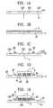
- FIGS. 1A-1Eare schematic sectional diagrams used to depict the procedural steps involved in the first preferred embodiment of the flip-chip packaging technology of the invention for fabricating a flip-chip package.
- the first stepis to prepare a first semiconductor chip 1 having an active surface 10 , where integrated circuit components are formed, and an inactive surface 11 , where no integrated circuit components are formed.
- the active surface 10is formed with at least one chip-bonding area 100 .
- a plurality of inner bonding pads 101are formed in the chip-bonding area 100
- a plurality of outer bonding pads 102are formed beyond the chip-bonding area 100 on the active surface 10 .
- These bonding pads 101 , 102are fabricated through conventional technology, so description thereof will not be further detailed.
- a polyimide coating 2is formed over the active surface 10 of the first semiconductor chip 1 . It is required that the thickness of the polyimide coating 2 be smaller than the height of the solder bumps used for flip-chip application so as to facilitate the subsequent reflow of the solder bumps.
- a dam structure 20is formed beyond the chip-bonding area 100 of the active surface 10 and between the chip-bonding area 100 and the outer bonding pads 102 by etching away selected portions of the polyimide coating 2 through, for example, a dry-etching process, or a wet-etching process, or a plasma-etching process.
- the dam structure 20encloses the chip-bonding area 100 and the inner bonding pads 101 .
- an UBM (Under Bump Metallization) processis performed on the inner bonding pads 101 on the active surface 10 of the first semiconductor chip 1 , so as to form an electrically-conductive barrier layer (not shown) to help increase the bonding strength of the inner bonding pads 101 to solder bumps.
- the UBM processis conventional technology so description thereof will not be further detailed.
- a second semiconductor chip 3is prepared, which has an active surface 30 .
- a plurality of solder bumps 4are formed on the active surface 30 of the second semiconductor chip 3 . By means of these solder bumps 4 , the second semiconductor chip 3 is electrically coupled to the first semiconductor chip 1 .
- a gap 5is undesirably left between the active surface 10 of the first semiconductor chip 1 and the active surface 30 of the second semiconductor chip 3 .
- the UBM processcan be first performed on the second semiconductor chip 3 , and then the solder bumps 4 are implanted on the inner bonding pads 101 on the active surface 10 of the first semiconductor chip 1 .
- a flip-chip underfill processis performed to form an underfill layer 6 from, for example epoxy resin, in the gap 5 between the first semiconductor chip 1 and the second semiconductor chip 3 .
- the underfill layer 6allows an increase to the mechanical bonding strength between the first semiconductor chip 1 and the second semiconductor chip 3 and a decrease to the stress on the solder bumps 4 .
- the dispensed resinwould be confined by the dam structure 20 to flow only toward and into the gap 5 without flashing to other areas beyond the dam structure 20 .
- the outer bonding pads 102can be substantially free of resin flash.
- the semiconductor chips 1 , 3can be electrically coupled to external circuitry, such a printed circuit board, by means of the outer bonding pads 102 .
- the first semiconductor chip 1has its inactive surface 11 mounted on a lead frame (not shown), or a substrate (not shown), another semiconductor chip (not shown), or a heat sink (not shown).
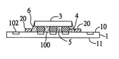
- FIG. 2is a schematic sectional diagram showing the second preferred embodiment of the flip-chip packaging technology of the invention.
- the same parts as the previous embodimentare labeled with the same reference numerals appended with an apostrophe.
- the flip-chip package structure of the second preferred embodimentalso includes a first semiconductor chip 1 ′ having an active surface 10 ′ and an inactive surface 11 ′.
- the active surface 10 ′is formed with at least one chip-bonding area 100 ′.
- a plurality of inner bonding pads 101 ′are formed in the chip-bonding area 100 ′, while a plurality of outer bonding pads 102 ′ are formed beyond the chip-bonding area 100 ′ on the active surface 10 ′.
- a polyimide coating 2 ′is formed over the active surface 10 ′ of the first semiconductor chip 1 ′, which is then selectively etched to form a plurality of openings 21 ′ to expose the inner bonding pads 101 ′ and the outer bonding pads 102 ′, with a remaining portion serving as a groove structure 20 ′.
- the openings 21 ′allow solder bumps 4 ′ to be directly implanted to the respective inner bonding pads 101 ′.
- the second semiconductor chip 3 ′can be electrically coupled to the first semiconductor chip 1 by means of these solder bumps 4 ′.
- a gap 5 ′is undesirably left between the first semiconductor chip 1 ′ and the second semiconductor chip 3 ′.
- a flip-chip underfill processis then performed to form an underfill layer 6 ′ in the gap 5 ′ to allow an increase to the mechanical bonding strength between the first semiconductor chip 1 ′ and the second semiconductor chip 3 ′.
- the dispensed resinwould be confined by the groove structure 20 ′ to flow only toward and into the gap 5 ′ without flashing to other areas beyond the groove structure 20 ′.
Landscapes
- Engineering & Computer Science (AREA)
- Computer Hardware Design (AREA)
- Microelectronics & Electronic Packaging (AREA)
- Power Engineering (AREA)
- Physics & Mathematics (AREA)
- Condensed Matter Physics & Semiconductors (AREA)
- General Physics & Mathematics (AREA)
- Manufacturing & Machinery (AREA)
- Wire Bonding (AREA)
- Structures Or Materials For Encapsulating Or Coating Semiconductor Devices Or Solid State Devices (AREA)
Abstract
Description
1. Field of the Invention
This invention relates to integrated circuit packaging technology, and more particularly, to a flip-chip packaging technology for use to fabricate a dual-chip integrated circuit package that includes two semiconductor chips in a single package unit.
2. Description of Related Art
The flip-chip packaging technology is an advanced integrated circuit packaging technology that allows the overall package size to be made very compact. The flip-chip package configuration differs from conventional art particularly in that it includes at least one semiconductor chip mounted in an upside-down manner over substrate or another semiconductor chip and electrically coupled to the same by means of solder bumps which are reflowed to solder pads on the flip-chip mounting surface. After the flip chip is readily bonded in position, however, a gap would be undesirably left between the chip and its underlying surface, which, if not underfilled, would easily cause the flip chip to suffer from fatigue cracking and electrical failure due to thermal stress when the entire package structure is being subjected to high-temperature conditions. As a solution to this problem, it is an essential step in flip-chip package fabrication to fill an underfill material, such as epoxy resin, into such a gap. The underfilled resin, when hardened, can serve as a mechanical reinforcement for the flip chip to cope against thermal stress. The involved fabrication process is customarily referred to as flip-chip underfill. By conventional flip-chip underfill technology, however, the underfill material would easily flow to other areas, causing undesired flash that would adversely affect subsequent wire-bonding process or passive-component mounting.
One solution to the foregoing problem is disclosed in the U.S. Pat. No. 5,218,234, which teaches the forming of a recessed portion in substrate to help prevent resin flash. In addition, the U.S. Pat. No. 5,120,678 teaches the forming of a dam structure on substrate to confine the underfill material within predefined area. These two patented technologies, however, are unsuitable for use on a dual-chip package structure wherein one chip is mounted in flip-chip manner over another one. This is because that it is required to form bonding pads on the active surface of the underlying chip (i.e., the carrier chip) for solder bonding to the overlying chip (i.e., the flip chip), and these bonding pads are located very near to the edge of the flip chip. In this case, the use of the patented technology of U.S. Pat. No. 5,120,678 would nevertheless cause resin flash on the bonding pads. As to the U.S. Pat. No. 5,218,234, since the underlying chip is provided without solder mask and with a plurality of exposed bonding pads, it is also unsuitable for use on a dual-chip package structure to solve the flash problem.
It is therefore an objective of this invention to provide a new flip-chip packaging technology that can help prevent the underfill material used in the flip-chip underfill process from flashing to other unintended areas and causing contamination to solder pads.
In accordance with the foregoing and other objectives, the invention proposes a new flip-chip packaging technology.
The flip-chip packaging technology comprises the following procedural steps: preparing a first semiconductor chip having an active surface and an inactive surface, with the active surface being formed with a chip-bonding area; wherein a plurality of inner bonding pads are formed in the chip-bonding area, while a plurality of outer bonding pads are formed beyond the chip-bonding area on the active surface; forming a coating layer over the active surface of the first semiconductor chip; etching away selected portions of the coating layer to expose the inner bonding pads and the outer bonding pads and meanwhile forming a flash-barrier structure around the chip-bonding area to separate the chip-bonding area from the outer bonding pads; electrically coupling a second semiconductor chip by means of solder bumps to the chip-bonding area on the first semiconductor chip, with a gap existing between the first semiconductor chip and the second semiconductor chip; and forming an underfill layer in the gap between the first semiconductor chip and the second semiconductor chip.
The flash-barrier structure can be either a protruded dam structure over the first semiconductor chip, or a groove in the coating layer, which can help prevent the underfill material from flowing to the areas therebeyond.
In terms of structure, the flip-chip packaging technology of the invention comprises: a first semiconductor chip having an active surface and an inactive surface, with the active surface being formed with a chip-bonding area; wherein a plurality of inner bonding pads are formed in the chip-bonding area, while a plurality of outer bonding pads are formed beyond the chip-bonding area on the active surface; a flash-barrier structure formed around the chip-bonding area of the first semiconductor chip to separate the chip-bonding area from the outer bonding pads; a second semiconductor chip electrically coupled to the first semiconductor chip by means of solder bumps to the chip-bonding area on the first semiconductor chip, with a gap existing between the first semiconductor chip and the second semiconductor chip; and an underfill layer formed in the gap between the first semiconductor chip and the second semiconductor chip.
The coating layer can be formed from, for example, polyimide or epoxy resin, and most preferably from polyimide.
The invention can be more fully understood by reading the following detailed description of the preferred embodiments, with reference made to the accompanying drawings, wherein:
FIGS. 1A-1E are schematic sectional diagrams used to depict the procedural steps involved in a first preferred embodiment of the flip-chip packaging technology of the invention;
FIG. 2 is a schematic sectional diagram showing a second preferred embodiment of the flip-chip packaging technology of the invention; and
FIG. 3 shows a schematic bottom view of the flip-chip package structure of FIG.2.
First Preferred Embodiment
FIGS. 1A-1E are schematic sectional diagrams used to depict the procedural steps involved in the first preferred embodiment of the flip-chip packaging technology of the invention for fabricating a flip-chip package.
Referring to FIG. 1A, the first step is to prepare afirst semiconductor chip 1 having anactive surface 10, where integrated circuit components are formed, and aninactive surface 11, where no integrated circuit components are formed. Theactive surface 10 is formed with at least one chip-bonding area 100. Further, a plurality ofinner bonding pads 101 are formed in the chip-bonding area 100, while a plurality ofouter bonding pads 102 are formed beyond the chip-bonding area 100 on theactive surface 10. Thesebonding pads
Referring further to FIG. 1B, in the next step, apolyimide coating 2 is formed over theactive surface 10 of thefirst semiconductor chip 1. It is required that the thickness of thepolyimide coating 2 be smaller than the height of the solder bumps used for flip-chip application so as to facilitate the subsequent reflow of the solder bumps.
Referring further to FIG. 1C, in the next step, adam structure 20 is formed beyond the chip-bonding area 100 of theactive surface 10 and between the chip-bonding area 100 and theouter bonding pads 102 by etching away selected portions of thepolyimide coating 2 through, for example, a dry-etching process, or a wet-etching process, or a plasma-etching process. Thedam structure 20 encloses the chip-bonding area 100 and theinner bonding pads 101.
Referring further to FIG. 1D, in the next step, an UBM (Under Bump Metallization) process is performed on theinner bonding pads 101 on theactive surface 10 of thefirst semiconductor chip 1, so as to form an electrically-conductive barrier layer (not shown) to help increase the bonding strength of theinner bonding pads 101 to solder bumps. The UBM process is conventional technology so description thereof will not be further detailed. Next, asecond semiconductor chip 3 is prepared, which has anactive surface 30. Further, a plurality ofsolder bumps 4 are formed on theactive surface 30 of thesecond semiconductor chip 3. By means of thesesolder bumps 4, thesecond semiconductor chip 3 is electrically coupled to thefirst semiconductor chip 1. Agap 5, however, is undesirably left between theactive surface 10 of thefirst semiconductor chip 1 and theactive surface 30 of thesecond semiconductor chip 3. Alternatively, the UBM process can be first performed on thesecond semiconductor chip 3, and then thesolder bumps 4 are implanted on theinner bonding pads 101 on theactive surface 10 of thefirst semiconductor chip 1.
Referring further to FIG. 1E, after solder reflow is completed, a flip-chip underfill process is performed to form anunderfill layer 6 from, for example epoxy resin, in thegap 5 between thefirst semiconductor chip 1 and thesecond semiconductor chip 3. Theunderfill layer 6 allows an increase to the mechanical bonding strength between thefirst semiconductor chip 1 and thesecond semiconductor chip 3 and a decrease to the stress on thesolder bumps 4. During this process, the dispensed resin would be confined by thedam structure 20 to flow only toward and into thegap 5 without flashing to other areas beyond thedam structure 20. As a result, theouter bonding pads 102 can be substantially free of resin flash.
In the foregoing flip-chip package structure, thesemiconductor chips outer bonding pads 102. Moreover, thefirst semiconductor chip 1 has itsinactive surface 11 mounted on a lead frame (not shown), or a substrate (not shown), another semiconductor chip (not shown), or a heat sink (not shown).
Second Preferred Embodiment
FIG. 2 is a schematic sectional diagram showing the second preferred embodiment of the flip-chip packaging technology of the invention. In FIG. 2, the same parts as the previous embodiment are labeled with the same reference numerals appended with an apostrophe.
As shown, the flip-chip package structure of the second preferred embodiment also includes afirst semiconductor chip 1′ having anactive surface 10′ and aninactive surface 11′. Theactive surface 10′ is formed with at least one chip-bonding area 100′. Further, a plurality ofinner bonding pads 101′ are formed in the chip-bonding area 100′, while a plurality ofouter bonding pads 102′ are formed beyond the chip-bonding area 100′ on theactive surface 10′.
Apolyimide coating 2′ is formed over theactive surface 10′ of thefirst semiconductor chip 1′, which is then selectively etched to form a plurality ofopenings 21′ to expose theinner bonding pads 101′ and theouter bonding pads 102′, with a remaining portion serving as agroove structure 20′. As shown in FIG. 3, theopenings 21′ allowsolder bumps 4′ to be directly implanted to the respectiveinner bonding pads 101′. After reflow of the solder bumps4′ to the corresponding I/O pads (not shown) on theactive surface 30′ of thesecond semiconductor chip 3′, thesecond semiconductor chip 3′ can be electrically coupled to thefirst semiconductor chip 1 by means of thesesolder bumps 4′. Agap 5′, however, is undesirably left between thefirst semiconductor chip 1′ and thesecond semiconductor chip 3′. A flip-chip underfill process is then performed to form anunderfill layer 6′ in thegap 5′ to allow an increase to the mechanical bonding strength between thefirst semiconductor chip 1′ and thesecond semiconductor chip 3′. During this process, the dispensed resin would be confined by thegroove structure 20′ to flow only toward and into thegap 5′ without flashing to other areas beyond thegroove structure 20′.
The invention has been described using exemplary preferred embodiments. However, it is to be understood that the scope of the invention is not limited to the disclosed embodiments. On the contrary, it is intended to cover various modifications and similar arrangements. The scope of the claims, therefore, should be accorded the broadest interpretation so as to encompass all such modifications and similar arrangements.
Claims (6)
1. A method for fabricating a flip-chip package, comprising the steps of:
preparing a first semiconductor chip having an active surface and an inactive surface, with the active surface being formed with a chip-bonding area; wherein a plurality of inner bonding pads are formed in the chip-bonding area, while a plurality of outer bonding pads are formed beyond the chip-bonding area on the active surface;
forming a coating layer over the active surface of the first semiconductor chip;
etching away selected portions of the coating layer to expose the inner bonding pads and the outer bonding pads and meanwhile forming a flash-barrier structure around the chip-bonding area to separate the chip-bonding area from the outer bonding pads;
electrically coupling a second semiconductor chip by means of solder bumps to the chip-bonding area on the first semiconductor chip, with a gap existing between the first semiconductor chip and the second semiconductor chip; and
forming an underfill layer in the gap between the first semiconductor chip and the second semiconductor chip.
2. The method of claim1, wherein the flash-barrier structure is a protruded dam structure over the first semiconductor chip.
3. The method of claim1, wherein the flash-barrier structure is a groove in the coating layer.
4. The method of claim1, wherein the coating layer is formed from polyimide.
5. The method of claim1, wherein the underfill layer is formed from epoxy resin.
6. The method of claim1, wherein the coating layer has a thickness smaller than the height of the solder bumps.
Priority Applications (2)
| Application Number | Priority Date | Filing Date | Title |
|---|---|---|---|
| US09/629,072US6291264B1 (en) | 2000-07-31 | 2000-07-31 | Flip-chip package structure and method of fabricating the same |
| US09/920,069US6400036B1 (en) | 2000-06-03 | 2001-08-01 | Flip-chip package structure and method of fabricating the same |
Applications Claiming Priority (1)
| Application Number | Priority Date | Filing Date | Title |
|---|---|---|---|
| US09/629,072US6291264B1 (en) | 2000-07-31 | 2000-07-31 | Flip-chip package structure and method of fabricating the same |
Related Child Applications (1)
| Application Number | Title | Priority Date | Filing Date |
|---|---|---|---|
| US09/920,069DivisionUS6400036B1 (en) | 2000-06-03 | 2001-08-01 | Flip-chip package structure and method of fabricating the same |
Publications (1)
| Publication Number | Publication Date |
|---|---|
| US6291264B1true US6291264B1 (en) | 2001-09-18 |
Family
ID=24521466
Family Applications (2)
| Application Number | Title | Priority Date | Filing Date |
|---|---|---|---|
| US09/629,072Expired - Fee RelatedUS6291264B1 (en) | 2000-06-03 | 2000-07-31 | Flip-chip package structure and method of fabricating the same |
| US09/920,069Expired - LifetimeUS6400036B1 (en) | 2000-06-03 | 2001-08-01 | Flip-chip package structure and method of fabricating the same |
Family Applications After (1)
| Application Number | Title | Priority Date | Filing Date |
|---|---|---|---|
| US09/920,069Expired - LifetimeUS6400036B1 (en) | 2000-06-03 | 2001-08-01 | Flip-chip package structure and method of fabricating the same |
Country Status (1)
| Country | Link |
|---|---|
| US (2) | US6291264B1 (en) |
Cited By (40)
| Publication number | Priority date | Publication date | Assignee | Title |
|---|---|---|---|---|
| US20020044213A1 (en)* | 2000-10-13 | 2002-04-18 | Kohji Shinomiya | Solid-state image pickup apparatus |
| US6521481B1 (en)* | 2002-01-07 | 2003-02-18 | Advanced Semiconductor Engineering, Inc. | Method for controlling adhesive distribution in a flip-chip semiconductor product |
| US6602737B2 (en)* | 2001-04-18 | 2003-08-05 | Siliconware Precision Industries Co., Ltd. | Semiconductor package with heat-dissipating structure and method of making the same |
| US6627979B2 (en)* | 2001-06-15 | 2003-09-30 | Dongbu Electronics Co., Ltd. | Semiconductor package and fabrication method of the same |
| US6731010B2 (en)* | 2000-09-14 | 2004-05-04 | Shinko Electric Industries Co., Ltd. | Resin sealed stacked semiconductor packages with flat surfaces |
| US20040184226A1 (en)* | 2003-03-18 | 2004-09-23 | Hall Frank L. | Bare die semiconductor dice underfilled and encapsulated with a single dielectric material and method for manufacturing the same |
| US20050017354A1 (en)* | 2003-05-21 | 2005-01-27 | Jens Paul | Arrangement for reducing stress in substrate-based chip packages |
| US20050195582A1 (en)* | 2004-03-02 | 2005-09-08 | Intel Corporation | Local control of underfill flow on high density packages, packages and systems made therewith, and methods of making same |
| US20060046352A1 (en)* | 2004-08-25 | 2006-03-02 | Low Al L | Substrate grooves to reduce underfill fillet bridging |
| US20060060985A1 (en)* | 2004-09-23 | 2006-03-23 | Furtaw Robert J | Semiconductor device having resin anti-bleed feature |
| US20060103030A1 (en)* | 2004-11-16 | 2006-05-18 | Makoto Aoki | Module substrate and disk apparatus |
| US20070187136A1 (en)* | 2004-09-29 | 2007-08-16 | Masahiro Higashiguchi | Printed circuit board, method of producing the same, and electronic unit |
| CN100373597C (en)* | 2005-01-25 | 2008-03-05 | 台湾积体电路制造股份有限公司 | Integrated circuit packaging structure and underfill process |
| US20080179738A1 (en)* | 2007-01-30 | 2008-07-31 | Fujitsu Limited | Wiring board and semiconductor device |
| US20080220564A1 (en)* | 2007-03-06 | 2008-09-11 | Infineon Technologies Ag | Semiconductor module |
| US20080246163A1 (en)* | 2004-09-28 | 2008-10-09 | Kazumasa Tanida | Semiconductor Device |
| US20090283317A1 (en)* | 2008-05-15 | 2009-11-19 | Shinko Electric Industries Co., Ltd. | Wiring board |
| US20090289350A1 (en)* | 2005-09-29 | 2009-11-26 | Nec Corporation | Semiconductor package, substrate, electronic device using such semiconductor package or substrate, and method for correcting warping of semiconductor package |
| US20100320581A1 (en)* | 2007-03-30 | 2010-12-23 | Oki Semiconductor Co., Ltd. | Semiconductor device |
| US20110074028A1 (en)* | 2004-10-07 | 2011-03-31 | Stats Chippac, Ltd. | Semiconductor Device and Method of Dissipating Heat From Thin Package-on-Package Mounted to Substrate |
| US20110204476A1 (en)* | 2007-04-30 | 2011-08-25 | Altera Corporation | Electronic Package with Fluid Flow Barriers |
| US20110260338A1 (en)* | 2010-04-27 | 2011-10-27 | Stats Chippac, Ltd. | Semiconductor Device and Method of Forming Adjacent Channel and DAM Material Around Die Attach Area of Substrate to Control Outward Flow of Underfill Material |
| US20120049355A1 (en)* | 2010-08-31 | 2012-03-01 | Ryuji Hosokawa | Semiconductor apparatus |
| US8253034B2 (en)* | 2010-05-24 | 2012-08-28 | Samsung Electro-Mechanics Co., Ltd. | Printed circuit board and semiconductor package with the same |
| USRE44438E1 (en)* | 2001-02-27 | 2013-08-13 | Stats Chippac, Ltd. | Semiconductor device and method of dissipating heat from thin package-on-package mounted to substrate |
| US20150001729A1 (en)* | 2013-06-27 | 2015-01-01 | Stats Chippac, Ltd. | Semiconductor Device and Method of Forming Trench and Disposing Semiconductor Die Over Substrate to Control Outward Flow of Underfill Material |
| US20150179614A1 (en)* | 2013-12-19 | 2015-06-25 | Sony Corporation | Semiconductor device and method of manufacturing semiconductor device |
| US20150262900A1 (en)* | 2014-03-14 | 2015-09-17 | Taiwan Semiconductor Manufacturing Company, Ltd. | Dam for Three-Dimensional Integrated Circuit |
| EP2733729A3 (en)* | 2012-11-19 | 2016-09-21 | J-Devices Corporation | Semiconductor device and method for producing the same |
| CN106098675A (en)* | 2015-04-27 | 2016-11-09 | 南茂科技股份有限公司 | Multi-chip packaging structure, wafer-level chip packaging structure and manufacturing process thereof |
| CN106206510A (en)* | 2015-04-27 | 2016-12-07 | 南茂科技股份有限公司 | Multi-chip packaging structure, wafer-level chip packaging structure and method thereof |
| US20170194226A1 (en)* | 2015-12-31 | 2017-07-06 | Taiwan Semiconductor Manufacturing Company, Ltd. | Underfill Control Structures and Method |
| US20180226271A1 (en)* | 2017-01-31 | 2018-08-09 | Skyworks Solutions, Inc. | Control of under-fill using a film during fabrication for a dual-sided ball grid array package |
| US11152226B2 (en) | 2019-10-15 | 2021-10-19 | International Business Machines Corporation | Structure with controlled capillary coverage |
| US11164756B2 (en)* | 2017-06-09 | 2021-11-02 | Advanced Semiconductor Engineering, Inc. | Semiconductor device package having continously formed tapered protrusions |
| US20220028809A1 (en)* | 2020-07-24 | 2022-01-27 | Innolux Corporation | Electronic substrate and electronic device |
| US11289454B2 (en) | 2019-10-14 | 2022-03-29 | Samsung Electronics Co., Ltd. | Semiconductor package including dam structure surrounding semiconductor chip and method of manufacturing the same |
| US20230023380A1 (en)* | 2021-07-23 | 2023-01-26 | Taiwan Semiconductor Manufacturing Company Limited | Underfill cushion films for packaging substrates and methods of forming the same |
| US20230317671A1 (en)* | 2022-03-30 | 2023-10-05 | Taiwan Semiconductor Manufacturing Company Limited | Substrate trench for controlling underfill fillet area and methods of forming the same |
| US11842972B2 (en) | 2004-09-28 | 2023-12-12 | Rohm Co., Ltd. | Semiconductor device with a semiconductor chip connected in a flip chip manner |
Families Citing this family (37)
| Publication number | Priority date | Publication date | Assignee | Title |
|---|---|---|---|---|
| SG97938A1 (en)* | 2000-09-21 | 2003-08-20 | Micron Technology Inc | Method to prevent die attach adhesive contamination in stacked chips |
| JP2002222914A (en)* | 2001-01-26 | 2002-08-09 | Sony Corp | Semiconductor device and manufacturing method therefor |
| KR100411811B1 (en)* | 2001-04-02 | 2003-12-24 | 앰코 테크놀로지 코리아 주식회사 | Semiconductor package |
| JP3649169B2 (en)* | 2001-08-08 | 2005-05-18 | 松下電器産業株式会社 | Semiconductor device |
| US20030223181A1 (en)* | 2002-05-28 | 2003-12-04 | Micron Technology, Inc. | Electronic device package |
| KR100576156B1 (en)* | 2003-10-22 | 2006-05-03 | 삼성전자주식회사 | Semiconductor device with dam and mounting structure of semiconductor device |
| TWI273681B (en)* | 2004-06-24 | 2007-02-11 | Advanced Semiconductor Eng | Semiconductor package with flip chip on leadless leadframe |
| JP4376160B2 (en)* | 2004-09-30 | 2009-12-02 | 株式会社リコー | Printed circuit board and circuit unit using the printed circuit board |
| US8294279B2 (en)* | 2005-01-25 | 2012-10-23 | Megica Corporation | Chip package with dam bar restricting flow of underfill |
| DE102006010511A1 (en)* | 2006-03-07 | 2007-09-13 | Infineon Technologies Ag | Vertical semiconductor arrangement e.g. semiconductor chip stack, for printed circuit board substrate, has auxiliary layer that is bounded on area of relevant main side or includes structure provided with recess, channel, wall and trench |
| TW200910540A (en)* | 2007-08-21 | 2009-03-01 | Advanced Semiconductor Eng | Package structure and manufacturing method thereof |
| CN100565864C (en)* | 2008-03-06 | 2009-12-02 | 日月光半导体制造股份有限公司 | Package structure and manufacturing method thereof |
| JP5277068B2 (en)* | 2008-07-14 | 2013-08-28 | パナソニック株式会社 | Connection method between substrates, flip chip mounting body, and connection structure between substrates |
| KR101481577B1 (en)* | 2008-09-29 | 2015-01-13 | 삼성전자주식회사 | Semiconductor package having dam of ink jet method and manufacturing method thereof |
| JP2010118575A (en)* | 2008-11-14 | 2010-05-27 | Nec Electronics Corp | Semiconductor device and method of manufacturing the same |
| WO2010089814A1 (en)* | 2009-02-04 | 2010-08-12 | パナソニック株式会社 | Semiconductor substrate structure and semiconductor device |
| US8367470B2 (en)* | 2009-08-07 | 2013-02-05 | Stats Chippac, Ltd. | Semiconductor device and method of forming cavity in build-up interconnect structure for short signal path between die |
| US8441123B1 (en)* | 2009-08-13 | 2013-05-14 | Amkor Technology, Inc. | Semiconductor device with metal dam and fabricating method |
| JP2011176112A (en)* | 2010-02-24 | 2011-09-08 | Renesas Electronics Corp | Semiconductor integrated circuit and method of manufacturing the same |
| US20110222256A1 (en)* | 2010-03-10 | 2011-09-15 | Topacio Roden R | Circuit board with anchored underfill |
| US8617926B2 (en) | 2010-09-09 | 2013-12-31 | Advanced Micro Devices, Inc. | Semiconductor chip device with polymeric filler trench |
| US8546957B2 (en)* | 2010-12-09 | 2013-10-01 | Stats Chippac Ltd. | Integrated circuit packaging system with dielectric support and method of manufacture thereof |
| US8409923B2 (en)* | 2011-06-15 | 2013-04-02 | Stats Chippac Ltd. | Integrated circuit packaging system with underfill and method of manufacture thereof |
| US9245773B2 (en) | 2011-09-02 | 2016-01-26 | Taiwan Semiconductor Manufacturing Company, Ltd. | Semiconductor device packaging methods and structures thereof |
| US9390060B2 (en)* | 2011-09-02 | 2016-07-12 | Taiwan Semiconductor Manufacturing Company, Ltd. | Packaging methods, material dispensing methods and apparatuses, and automated measurement systems |
| US8772083B2 (en) | 2011-09-10 | 2014-07-08 | Ati Technologies Ulc | Solder mask with anchor structures |
| US8680647B2 (en)* | 2011-12-29 | 2014-03-25 | Taiwan Semiconductor Manufacturing Company, Ltd. | Packages with passive devices and methods of forming the same |
| US9406579B2 (en)* | 2012-05-14 | 2016-08-02 | STATS ChipPAC Pte. Ltd. | Semiconductor device and method of controlling warpage in semiconductor package |
| US8809996B2 (en) | 2012-06-29 | 2014-08-19 | Taiwan Semiconductor Manufacturing Company, Ltd. | Package with passive devices and method of forming the same |
| US8895365B2 (en)* | 2012-08-31 | 2014-11-25 | Intel Corporation | Techniques and configurations for surface treatment of an integrated circuit substrate |
| US9245815B2 (en)* | 2014-04-29 | 2016-01-26 | Intel Corporation | Underfill material including block copolymer to tune coefficient of thermal expansion and tensile modulus |
| KR102374107B1 (en) | 2015-10-07 | 2022-03-14 | 삼성전자주식회사 | Method for manufacturing semiconductor package |
| WO2018125166A1 (en)* | 2016-12-29 | 2018-07-05 | Intel Corporation | Package with underfill containment barrier |
| US10217649B2 (en)* | 2017-06-09 | 2019-02-26 | Advanced Semiconductor Engineering, Inc. | Semiconductor device package having an underfill barrier |
| US11094625B2 (en)* | 2019-01-02 | 2021-08-17 | Taiwan Semiconductor Manufacturing Co., Ltd. | Semiconductor package with improved interposer structure |
| CN113972308B (en)* | 2020-07-24 | 2025-08-26 | 群创光电股份有限公司 | Electronic substrate and electronic device |
| US20240339429A1 (en)* | 2023-04-06 | 2024-10-10 | Avago Technologies International Sales Pte. Limited | Packaging systems and methods for semiconductor devices |
Citations (5)
| Publication number | Priority date | Publication date | Assignee | Title |
|---|---|---|---|---|
| US4818728A (en)* | 1986-12-03 | 1989-04-04 | Sharp Kabushiki Kaisha | Method of making a hybrid semiconductor device |
| US5120678A (en) | 1990-11-05 | 1992-06-09 | Motorola Inc. | Electrical component package comprising polymer-reinforced solder bump interconnection |
| US5218234A (en) | 1991-12-23 | 1993-06-08 | Motorola, Inc. | Semiconductor device with controlled spread polymeric underfill |
| US6048656A (en)* | 1999-05-11 | 2000-04-11 | Micron Technology, Inc. | Void-free underfill of surface mounted chips |
| US6214635B1 (en)* | 1996-03-07 | 2001-04-10 | Micron Technology, Inc. | Method and apparatus for underfill of bumped or raised die |
Family Cites Families (3)
| Publication number | Priority date | Publication date | Assignee | Title |
|---|---|---|---|---|
| US6265776B1 (en)* | 1998-04-27 | 2001-07-24 | Fry's Metals, Inc. | Flip chip with integrated flux and underfill |
| US6228681B1 (en)* | 1999-03-10 | 2001-05-08 | Fry's Metals, Inc. | Flip chip having integral mask and underfill providing two-stage bump formation |
| US6245595B1 (en)* | 1999-07-22 | 2001-06-12 | National Semiconductor Corporation | Techniques for wafer level molding of underfill encapsulant |
- 2000
- 2000-07-31USUS09/629,072patent/US6291264B1/ennot_activeExpired - Fee Related
- 2001
- 2001-08-01USUS09/920,069patent/US6400036B1/ennot_activeExpired - Lifetime
Patent Citations (5)
| Publication number | Priority date | Publication date | Assignee | Title |
|---|---|---|---|---|
| US4818728A (en)* | 1986-12-03 | 1989-04-04 | Sharp Kabushiki Kaisha | Method of making a hybrid semiconductor device |
| US5120678A (en) | 1990-11-05 | 1992-06-09 | Motorola Inc. | Electrical component package comprising polymer-reinforced solder bump interconnection |
| US5218234A (en) | 1991-12-23 | 1993-06-08 | Motorola, Inc. | Semiconductor device with controlled spread polymeric underfill |
| US6214635B1 (en)* | 1996-03-07 | 2001-04-10 | Micron Technology, Inc. | Method and apparatus for underfill of bumped or raised die |
| US6048656A (en)* | 1999-05-11 | 2000-04-11 | Micron Technology, Inc. | Void-free underfill of surface mounted chips |
Cited By (87)
| Publication number | Priority date | Publication date | Assignee | Title |
|---|---|---|---|---|
| US6731010B2 (en)* | 2000-09-14 | 2004-05-04 | Shinko Electric Industries Co., Ltd. | Resin sealed stacked semiconductor packages with flat surfaces |
| US20020044213A1 (en)* | 2000-10-13 | 2002-04-18 | Kohji Shinomiya | Solid-state image pickup apparatus |
| US6977686B2 (en)* | 2000-10-13 | 2005-12-20 | Renesas Technology Corp. | Solid-state image pickup apparatus limiting adhesive intrusion |
| US8941235B2 (en) | 2001-02-27 | 2015-01-27 | Stats Chippac, Ltd. | Semiconductor device and method of dissipating heat from thin package-on-package mounted to substrate |
| USRE44438E1 (en)* | 2001-02-27 | 2013-08-13 | Stats Chippac, Ltd. | Semiconductor device and method of dissipating heat from thin package-on-package mounted to substrate |
| US6753602B2 (en) | 2001-04-18 | 2004-06-22 | Siliconware Precision Industries Co., Ltd. | Semiconductor package with heat-dissipating structure and method of making the same |
| US6602737B2 (en)* | 2001-04-18 | 2003-08-05 | Siliconware Precision Industries Co., Ltd. | Semiconductor package with heat-dissipating structure and method of making the same |
| US6627979B2 (en)* | 2001-06-15 | 2003-09-30 | Dongbu Electronics Co., Ltd. | Semiconductor package and fabrication method of the same |
| US6521481B1 (en)* | 2002-01-07 | 2003-02-18 | Advanced Semiconductor Engineering, Inc. | Method for controlling adhesive distribution in a flip-chip semiconductor product |
| US20050253241A1 (en)* | 2003-03-18 | 2005-11-17 | Hall Frank L | Semiconductor device assemblies including an encapsulant located over intermediate conductive elements and filling a space between a semiconductor die and a carrier of the assembly |
| US20050263906A1 (en)* | 2003-03-18 | 2005-12-01 | Hall Frank L | Electronic system including a semiconductor device with at least one semiconductor die, a carrier, and an encapsulant that fills a space between the die and the carrier and covers intermediate conductive elements that connect the die and the carrier |
| US20040184226A1 (en)* | 2003-03-18 | 2004-09-23 | Hall Frank L. | Bare die semiconductor dice underfilled and encapsulated with a single dielectric material and method for manufacturing the same |
| US6987058B2 (en) | 2003-03-18 | 2006-01-17 | Micron Technology, Inc. | Methods for underfilling and encapsulating semiconductor device assemblies with a single dielectric material |
| US20050017354A1 (en)* | 2003-05-21 | 2005-01-27 | Jens Paul | Arrangement for reducing stress in substrate-based chip packages |
| US7180162B2 (en)* | 2003-05-21 | 2007-02-20 | Infineon Technologies Ag | Arrangement for reducing stress in substrate-based chip packages |
| US20050195582A1 (en)* | 2004-03-02 | 2005-09-08 | Intel Corporation | Local control of underfill flow on high density packages, packages and systems made therewith, and methods of making same |
| US20080150099A1 (en)* | 2004-03-02 | 2008-06-26 | Juan Landeros | Local control of underfill flow on high density packages, packages and systems made therewith, and methods of making same |
| US7359211B2 (en)* | 2004-03-02 | 2008-04-15 | Intel Corporation | Local control of underfill flow on high density packages, packages and systems made therewith, and methods of making same |
| US20060046352A1 (en)* | 2004-08-25 | 2006-03-02 | Low Al L | Substrate grooves to reduce underfill fillet bridging |
| US7179683B2 (en)* | 2004-08-25 | 2007-02-20 | Intel Corporation | Substrate grooves to reduce underfill fillet bridging |
| US7183657B2 (en)* | 2004-09-23 | 2007-02-27 | Texas Instruments Incorporated | Semiconductor device having resin anti-bleed feature |
| US20070116862A1 (en)* | 2004-09-23 | 2007-05-24 | Texas Instruments Incorporated | Semiconductor Device Having Resin Anti-Bleed Feature |
| US20060060985A1 (en)* | 2004-09-23 | 2006-03-23 | Furtaw Robert J | Semiconductor device having resin anti-bleed feature |
| US9117774B2 (en) | 2004-09-28 | 2015-08-25 | Rohm Co., Ltd. | Semiconductor device with a semiconductor chip connected in a flip chip manner |
| US10818628B2 (en) | 2004-09-28 | 2020-10-27 | Rohm Co., Ltd. | Semiconductor device with a semiconductor chip connected in a flip chip manner |
| US10522494B2 (en) | 2004-09-28 | 2019-12-31 | Rohm Co., Ltd. | Semiconductor device with a semiconductor chip connected in a flip chip manner |
| US20080246163A1 (en)* | 2004-09-28 | 2008-10-09 | Kazumasa Tanida | Semiconductor Device |
| US9831204B2 (en) | 2004-09-28 | 2017-11-28 | Rohm Co., Ltd. | Semiconductor device with a semiconductor chip connected in a flip chip manner |
| US9721865B2 (en) | 2004-09-28 | 2017-08-01 | Rohm Co., Ltd. | Semiconductor device with a semiconductor chip connected in a flip chip manner |
| US11842972B2 (en) | 2004-09-28 | 2023-12-12 | Rohm Co., Ltd. | Semiconductor device with a semiconductor chip connected in a flip chip manner |
| US8754535B2 (en) | 2004-09-28 | 2014-06-17 | Rohm Co., Ltd. | Semiconductor device with a semiconductor chip connected in a flip chip manner |
| US11355462B2 (en) | 2004-09-28 | 2022-06-07 | Rohm Co., Ltd. | Semiconductor device with a semiconductor chip connected in a flip chip manner |
| US8405227B2 (en) | 2004-09-28 | 2013-03-26 | Rohm Co., Ltd. | Semiconductor device with a semiconductor chip connected in a flip chip manner |
| US20070187136A1 (en)* | 2004-09-29 | 2007-08-16 | Masahiro Higashiguchi | Printed circuit board, method of producing the same, and electronic unit |
| US8143108B2 (en)* | 2004-10-07 | 2012-03-27 | Stats Chippac, Ltd. | Semiconductor device and method of dissipating heat from thin package-on-package mounted to substrate |
| US20110074028A1 (en)* | 2004-10-07 | 2011-03-31 | Stats Chippac, Ltd. | Semiconductor Device and Method of Dissipating Heat From Thin Package-on-Package Mounted to Substrate |
| US7327040B2 (en) | 2004-11-16 | 2008-02-05 | Kabushiki Kaisha Toshiba | Module substrate and disk apparatus |
| US20060103030A1 (en)* | 2004-11-16 | 2006-05-18 | Makoto Aoki | Module substrate and disk apparatus |
| CN100373597C (en)* | 2005-01-25 | 2008-03-05 | 台湾积体电路制造股份有限公司 | Integrated circuit packaging structure and underfill process |
| US20090289350A1 (en)* | 2005-09-29 | 2009-11-26 | Nec Corporation | Semiconductor package, substrate, electronic device using such semiconductor package or substrate, and method for correcting warping of semiconductor package |
| US20080179738A1 (en)* | 2007-01-30 | 2008-07-31 | Fujitsu Limited | Wiring board and semiconductor device |
| US7880276B2 (en)* | 2007-01-30 | 2011-02-01 | Fujitsu Semiconductor Limited | Wiring board and semiconductor device |
| US20080220564A1 (en)* | 2007-03-06 | 2008-09-11 | Infineon Technologies Ag | Semiconductor module |
| US7705441B2 (en)* | 2007-03-06 | 2010-04-27 | Infineon Technologies Ag | Semiconductor module |
| US20100320581A1 (en)* | 2007-03-30 | 2010-12-23 | Oki Semiconductor Co., Ltd. | Semiconductor device |
| US8432025B2 (en)* | 2007-03-30 | 2013-04-30 | Lapis Semiconductor Co., Ltd. | Semiconductor device and plurality of dams |
| US20110204476A1 (en)* | 2007-04-30 | 2011-08-25 | Altera Corporation | Electronic Package with Fluid Flow Barriers |
| US8710643B2 (en)* | 2007-04-30 | 2014-04-29 | Altera Corporation | Electronic package with fluid flow barriers |
| US8378482B2 (en)* | 2008-05-15 | 2013-02-19 | Shinko Electric Industries Co., Ltd. | Wiring board |
| US20090283317A1 (en)* | 2008-05-15 | 2009-11-19 | Shinko Electric Industries Co., Ltd. | Wiring board |
| US9030030B2 (en) | 2010-04-27 | 2015-05-12 | Stats Chippac, Ltd. | Semiconductor device and method of forming adjacent channel and dam material around die attach area of substrate to control outward flow of underfill material |
| US20110260338A1 (en)* | 2010-04-27 | 2011-10-27 | Stats Chippac, Ltd. | Semiconductor Device and Method of Forming Adjacent Channel and DAM Material Around Die Attach Area of Substrate to Control Outward Flow of Underfill Material |
| US8399300B2 (en)* | 2010-04-27 | 2013-03-19 | Stats Chippac, Ltd. | Semiconductor device and method of forming adjacent channel and DAM material around die attach area of substrate to control outward flow of underfill material |
| US8253034B2 (en)* | 2010-05-24 | 2012-08-28 | Samsung Electro-Mechanics Co., Ltd. | Printed circuit board and semiconductor package with the same |
| US8759971B2 (en)* | 2010-08-31 | 2014-06-24 | Kabushiki Kaisha Toshiba | Semiconductor apparatus |
| US20120049355A1 (en)* | 2010-08-31 | 2012-03-01 | Ryuji Hosokawa | Semiconductor apparatus |
| EP2733729A3 (en)* | 2012-11-19 | 2016-09-21 | J-Devices Corporation | Semiconductor device and method for producing the same |
| US20150001729A1 (en)* | 2013-06-27 | 2015-01-01 | Stats Chippac, Ltd. | Semiconductor Device and Method of Forming Trench and Disposing Semiconductor Die Over Substrate to Control Outward Flow of Underfill Material |
| US9627229B2 (en)* | 2013-06-27 | 2017-04-18 | STATS ChipPAC Pte. Ltd. | Semiconductor device and method of forming trench and disposing semiconductor die over substrate to control outward flow of underfill material |
| US20150179614A1 (en)* | 2013-12-19 | 2015-06-25 | Sony Corporation | Semiconductor device and method of manufacturing semiconductor device |
| US9368480B2 (en)* | 2013-12-19 | 2016-06-14 | Sony Corporation | Semiconductor device and method of manufacturing semiconductor device |
| US10867878B2 (en) | 2014-03-14 | 2020-12-15 | Taiwan Semiconductor Manufacturing Company | Dam for three-dimensional integrated circuit |
| US10020236B2 (en)* | 2014-03-14 | 2018-07-10 | Taiwan Semiconductar Manufacturing Campany | Dam for three-dimensional integrated circuit |
| US20150262900A1 (en)* | 2014-03-14 | 2015-09-17 | Taiwan Semiconductor Manufacturing Company, Ltd. | Dam for Three-Dimensional Integrated Circuit |
| US9728479B2 (en)* | 2015-04-27 | 2017-08-08 | Chipmos Technologies Inc. | Multi-chip package structure, wafer level chip package structure and manufacturing process thereof |
| US10002815B2 (en)* | 2015-04-27 | 2018-06-19 | Chipmos Technologies Inc. | Multi-chip package structure manufacturing process and wafer level chip package structure manufacturing process |
| CN106098675B (en)* | 2015-04-27 | 2019-05-07 | 南茂科技股份有限公司 | Multi-chip packaging structure, wafer-level chip packaging structure and manufacturing process thereof |
| CN106098675A (en)* | 2015-04-27 | 2016-11-09 | 南茂科技股份有限公司 | Multi-chip packaging structure, wafer-level chip packaging structure and manufacturing process thereof |
| CN106206510A (en)* | 2015-04-27 | 2016-12-07 | 南茂科技股份有限公司 | Multi-chip packaging structure, wafer-level chip packaging structure and method thereof |
| US11018069B2 (en) | 2015-12-31 | 2021-05-25 | Taiwan Semiconductor Manufacturing Company, Ltd. | Underfill control structures and method |
| US20170194226A1 (en)* | 2015-12-31 | 2017-07-06 | Taiwan Semiconductor Manufacturing Company, Ltd. | Underfill Control Structures and Method |
| US9842788B2 (en)* | 2015-12-31 | 2017-12-12 | Taiwan Semiconductor Manufacturing Company, Ltd. | Underfill control structures and method |
| US10515865B2 (en) | 2015-12-31 | 2019-12-24 | Taiwan Semiconductor Manufacturing Company, Ltd. | Underfill control structures and method |
| US10410885B2 (en) | 2017-01-31 | 2019-09-10 | Skyworks Solutions, Inc. | Control of under-fill using under-fill deflash for a dual-sided ball grid array package |
| US10593565B2 (en) | 2017-01-31 | 2020-03-17 | Skyworks Solutions, Inc. | Control of under-fill with a packaging substrate having an integrated trench for a dual-sided ball grid array package |
| US10460957B2 (en) | 2017-01-31 | 2019-10-29 | Skyworks Solutions, Inc. | Control of under-fill using an encapsulant for a dual-sided ball grid array package |
| US20180226271A1 (en)* | 2017-01-31 | 2018-08-09 | Skyworks Solutions, Inc. | Control of under-fill using a film during fabrication for a dual-sided ball grid array package |
| US11201066B2 (en) | 2017-01-31 | 2021-12-14 | Skyworks Solutions, Inc. | Control of under-fill using a dam on a packaging substrate for a dual-sided ball grid array package |
| US11164756B2 (en)* | 2017-06-09 | 2021-11-02 | Advanced Semiconductor Engineering, Inc. | Semiconductor device package having continously formed tapered protrusions |
| US11742331B2 (en) | 2019-10-14 | 2023-08-29 | Samsung Electronics Co., Ltd. | Method of manufacturing a semiconductor package including a dam structure surrounding a semiconductor chip mounting region |
| US11289454B2 (en) | 2019-10-14 | 2022-03-29 | Samsung Electronics Co., Ltd. | Semiconductor package including dam structure surrounding semiconductor chip and method of manufacturing the same |
| US11152226B2 (en) | 2019-10-15 | 2021-10-19 | International Business Machines Corporation | Structure with controlled capillary coverage |
| US20220028809A1 (en)* | 2020-07-24 | 2022-01-27 | Innolux Corporation | Electronic substrate and electronic device |
| US11830833B2 (en)* | 2020-07-24 | 2023-11-28 | Innolux Corporation | Electronic substrate and electronic device |
| US20230023380A1 (en)* | 2021-07-23 | 2023-01-26 | Taiwan Semiconductor Manufacturing Company Limited | Underfill cushion films for packaging substrates and methods of forming the same |
| US12394698B2 (en)* | 2021-07-23 | 2025-08-19 | Taiwan Semiconductor Manufacturing Company Limited | Underfill cushion films for packaging substrates and methods of forming the same |
| US20230317671A1 (en)* | 2022-03-30 | 2023-10-05 | Taiwan Semiconductor Manufacturing Company Limited | Substrate trench for controlling underfill fillet area and methods of forming the same |
Also Published As
| Publication number | Publication date |
|---|---|
| US6400036B1 (en) | 2002-06-04 |
| US20020028533A1 (en) | 2002-03-07 |
Similar Documents
| Publication | Publication Date | Title |
|---|---|---|
| US6291264B1 (en) | Flip-chip package structure and method of fabricating the same | |
| US6600232B2 (en) | Flip-chip semiconductor package structure and process for fabricating the same | |
| US7476564B2 (en) | Flip-chip packaging process using copper pillar as bump structure | |
| US9935072B2 (en) | Semiconductor package and method for manufacturing the same | |
| US8217520B2 (en) | System-in-package packaging for minimizing bond wire contamination and yield loss | |
| JP3689694B2 (en) | Semiconductor device and manufacturing method thereof | |
| US5731631A (en) | Semiconductor device with tape automated bonding element | |
| CN106471612B (en) | Semiconductor device and method of manufacturing the same | |
| KR20180086804A (en) | Semiconductor device and manufacturing method thereof | |
| CN106463426B (en) | Semiconductor device and method for manufacturing the same | |
| US20070111398A1 (en) | Micro-electronic package structure and method for fabricating the same | |
| US8253248B2 (en) | Fabrication method of semiconductor device having conductive bumps | |
| US6391682B1 (en) | Method of performing flip-chip underfill in a wire-bonded chip-on-chip ball-grid array integrated circuit package module | |
| US7368806B2 (en) | Flip chip package with anti-floating structure | |
| KR20160004065A (en) | Semiconductor package and method of manufacturing the same | |
| JP2003224158A (en) | Flip chip for substrate assembly with no bump and polymer layer | |
| CN106463427B (en) | Semiconductor device and method for manufacturing the same | |
| US20060214308A1 (en) | Flip-chip semiconductor package and method for fabricating the same | |
| JPH08102475A (en) | Carrier film | |
| US20060068332A1 (en) | Method for fabricating carrier structure integrated with semiconductor element | |
| US20080284015A1 (en) | Bump on via-packaging and methodologies | |
| US20040089946A1 (en) | Chip size semiconductor package structure | |
| US20050056933A1 (en) | Bumped wafer with adhesive layer encompassing bumps and manufacturing method thereof | |
| KR20200056598A (en) | Wafer-level package including under bump metal layer | |
| JP2001210667A (en) | Manufacturing method for semiconductor device |
Legal Events
| Date | Code | Title | Description |
|---|---|---|---|
| AS | Assignment | Owner name:SILICONWARE PRECISION INDUSTRIES CO., LTD., TAIWAN Free format text:ASSIGNMENT OF ASSIGNORS INTEREST;ASSIGNORS:TANG, WEI-SEN;PU, HAN-PING;REEL/FRAME:010985/0903 Effective date:20000428 | |
| FPAY | Fee payment | Year of fee payment:4 | |
| REMI | Maintenance fee reminder mailed | ||
| LAPS | Lapse for failure to pay maintenance fees | ||
| STCH | Information on status: patent discontinuation | Free format text:PATENT EXPIRED DUE TO NONPAYMENT OF MAINTENANCE FEES UNDER 37 CFR 1.362 | |
| FP | Lapsed due to failure to pay maintenance fee | Effective date:20090918 |