US6290724B1 - Methods for separating and stabilizing adjacent vertebrae - Google Patents
Methods for separating and stabilizing adjacent vertebraeDownload PDFInfo
- Publication number
- US6290724B1 US6290724B1US09/320,161US32016199AUS6290724B1US 6290724 B1US6290724 B1US 6290724B1US 32016199 AUS32016199 AUS 32016199AUS 6290724 B1US6290724 B1US 6290724B1
- Authority
- US
- United States
- Prior art keywords
- insert
- adjacent vertebrae
- vertebrae
- cannula
- inserts
- Prior art date
- Legal status (The legal status is an assumption and is not a legal conclusion. Google has not performed a legal analysis and makes no representation as to the accuracy of the status listed.)
- Expired - Lifetime
Links
- 238000000034methodMethods0.000titleclaimsabstractdescription73
- 230000000087stabilizing effectEffects0.000titleclaimsabstractdescription11
- 238000004873anchoringMethods0.000claimsabstractdescription22
- 239000007943implantSubstances0.000claimsdescription19
- 238000003780insertionMethods0.000claimsdescription14
- 230000037431insertionEffects0.000claimsdescription13
- 238000000926separation methodMethods0.000claimsdescription10
- 230000000149penetrating effectEffects0.000claimsdescription4
- 210000000988bone and boneAnatomy0.000description31
- 239000000463materialSubstances0.000description19
- 210000001519tissueAnatomy0.000description19
- 230000008901benefitEffects0.000description15
- 230000033001locomotionEffects0.000description14
- 238000001356surgical procedureMethods0.000description10
- 238000013459approachMethods0.000description9
- 230000004927fusionEffects0.000description8
- 210000004446longitudinal ligamentAnatomy0.000description8
- 208000007623LordosisDiseases0.000description7
- 230000008468bone growthEffects0.000description7
- 210000003041ligamentAnatomy0.000description5
- 230000001045lordotic effectEffects0.000description5
- 230000000399orthopedic effectEffects0.000description5
- 230000011164ossificationEffects0.000description5
- 230000006378damageEffects0.000description4
- 230000006641stabilisationEffects0.000description4
- 238000011105stabilizationMethods0.000description4
- 208000008558OsteophyteDiseases0.000description3
- 229920000954PolyglycolidePolymers0.000description3
- 239000002775capsuleSubstances0.000description3
- 239000013078crystalSubstances0.000description3
- 230000007850degenerationEffects0.000description3
- 238000006073displacement reactionMethods0.000description3
- 238000005553drillingMethods0.000description3
- 238000002513implantationMethods0.000description3
- 230000007774longtermEffects0.000description3
- 238000005259measurementMethods0.000description3
- 229920001432poly(L-lactide)Polymers0.000description3
- 239000004633polyglycolic acidSubstances0.000description3
- 229910001220stainless steelInorganic materials0.000description3
- 239000010935stainless steelSubstances0.000description3
- 230000000451tissue damageEffects0.000description3
- 231100000827tissue damageToxicity0.000description3
- 210000002517zygapophyseal jointAnatomy0.000description3
- 102000008186CollagenHuman genes0.000description2
- 108010035532CollagenProteins0.000description2
- RTAQQCXQSZGOHL-UHFFFAOYSA-NTitaniumChemical compound[Ti]RTAQQCXQSZGOHL-UHFFFAOYSA-N0.000description2
- 238000010521absorption reactionMethods0.000description2
- 239000000560biocompatible materialSubstances0.000description2
- 229920001436collagenPolymers0.000description2
- 238000013500data storageMethods0.000description2
- 230000035876healingEffects0.000description2
- 208000014674injuryDiseases0.000description2
- 230000009545invasionEffects0.000description2
- VNWKTOKETHGBQD-UHFFFAOYSA-NmethaneChemical classCVNWKTOKETHGBQD-UHFFFAOYSA-N0.000description2
- 239000000203mixtureSubstances0.000description2
- 230000002980postoperative effectEffects0.000description2
- 230000003252repetitive effectEffects0.000description2
- 239000010936titaniumSubstances0.000description2
- 229910052719titaniumInorganic materials0.000description2
- 230000008733traumaEffects0.000description2
- 206010065687Bone lossDiseases0.000description1
- 210000001015abdomenAnatomy0.000description1
- 230000032683agingEffects0.000description1
- 239000002639bone cementSubstances0.000description1
- 239000001506calcium phosphateSubstances0.000description1
- 235000011010calcium phosphatesNutrition0.000description1
- 239000000919ceramicSubstances0.000description1
- 238000005520cutting processMethods0.000description1
- 230000001351cycling effectEffects0.000description1
- 230000003247decreasing effectEffects0.000description1
- 230000006866deteriorationEffects0.000description1
- 201000010934exostosisDiseases0.000description1
- 238000004519manufacturing processMethods0.000description1
- 229910052751metalInorganic materials0.000description1
- 239000002184metalSubstances0.000description1
- 238000002324minimally invasive surgeryMethods0.000description1
- 210000005036nerveAnatomy0.000description1
- 230000000926neurological effectEffects0.000description1
- 238000002355open surgical procedureMethods0.000description1
- 230000002138osteoinductive effectEffects0.000description1
- 239000005022packaging materialSubstances0.000description1
- RFWLACFDYFIVMC-UHFFFAOYSA-Dpentacalcium;[oxido(phosphonatooxy)phosphoryl] phosphateChemical class[Ca+2].[Ca+2].[Ca+2].[Ca+2].[Ca+2].[O-]P([O-])(=O)OP([O-])(=O)OP([O-])([O-])=O.[O-]P([O-])(=O)OP([O-])(=O)OP([O-])([O-])=ORFWLACFDYFIVMC-UHFFFAOYSA-D0.000description1
- 230000000737periodic effectEffects0.000description1
- 238000003825pressingMethods0.000description1
- 230000001737promoting effectEffects0.000description1
- 238000011084recoveryMethods0.000description1
- 230000037390scarringEffects0.000description1
- 230000035882stressEffects0.000description1
- QORWJWZARLRLPR-UHFFFAOYSA-Htricalcium bis(phosphate)Chemical class[Ca+2].[Ca+2].[Ca+2].[O-]P([O-])([O-])=O.[O-]P([O-])([O-])=OQORWJWZARLRLPR-UHFFFAOYSA-H0.000description1
Images


Classifications
- A—HUMAN NECESSITIES
- A61—MEDICAL OR VETERINARY SCIENCE; HYGIENE
- A61F—FILTERS IMPLANTABLE INTO BLOOD VESSELS; PROSTHESES; DEVICES PROVIDING PATENCY TO, OR PREVENTING COLLAPSING OF, TUBULAR STRUCTURES OF THE BODY, e.g. STENTS; ORTHOPAEDIC, NURSING OR CONTRACEPTIVE DEVICES; FOMENTATION; TREATMENT OR PROTECTION OF EYES OR EARS; BANDAGES, DRESSINGS OR ABSORBENT PADS; FIRST-AID KITS
- A61F2/00—Filters implantable into blood vessels; Prostheses, i.e. artificial substitutes or replacements for parts of the body; Appliances for connecting them with the body; Devices providing patency to, or preventing collapsing of, tubular structures of the body, e.g. stents
- A61F2/02—Prostheses implantable into the body
- A61F2/30—Joints
- A61F2/44—Joints for the spine, e.g. vertebrae, spinal discs
- A61F2/4455—Joints for the spine, e.g. vertebrae, spinal discs for the fusion of spinal bodies, e.g. intervertebral fusion of adjacent spinal bodies, e.g. fusion cages
- A—HUMAN NECESSITIES
- A61—MEDICAL OR VETERINARY SCIENCE; HYGIENE
- A61F—FILTERS IMPLANTABLE INTO BLOOD VESSELS; PROSTHESES; DEVICES PROVIDING PATENCY TO, OR PREVENTING COLLAPSING OF, TUBULAR STRUCTURES OF THE BODY, e.g. STENTS; ORTHOPAEDIC, NURSING OR CONTRACEPTIVE DEVICES; FOMENTATION; TREATMENT OR PROTECTION OF EYES OR EARS; BANDAGES, DRESSINGS OR ABSORBENT PADS; FIRST-AID KITS
- A61F2/00—Filters implantable into blood vessels; Prostheses, i.e. artificial substitutes or replacements for parts of the body; Appliances for connecting them with the body; Devices providing patency to, or preventing collapsing of, tubular structures of the body, e.g. stents
- A61F2/02—Prostheses implantable into the body
- A61F2/30—Joints
- A61F2/46—Special tools for implanting artificial joints
- A61F2/4603—Special tools for implanting artificial joints for insertion or extraction of endoprosthetic joints or of accessories thereof
- A61F2/4611—Special tools for implanting artificial joints for insertion or extraction of endoprosthetic joints or of accessories thereof of spinal prostheses
- A—HUMAN NECESSITIES
- A61—MEDICAL OR VETERINARY SCIENCE; HYGIENE
- A61B—DIAGNOSIS; SURGERY; IDENTIFICATION
- A61B17/00—Surgical instruments, devices or methods
- A61B17/02—Surgical instruments, devices or methods for holding wounds open, e.g. retractors; Tractors
- A61B17/025—Joint distractors
- A61B2017/0256—Joint distractors for the spine
- A—HUMAN NECESSITIES
- A61—MEDICAL OR VETERINARY SCIENCE; HYGIENE
- A61F—FILTERS IMPLANTABLE INTO BLOOD VESSELS; PROSTHESES; DEVICES PROVIDING PATENCY TO, OR PREVENTING COLLAPSING OF, TUBULAR STRUCTURES OF THE BODY, e.g. STENTS; ORTHOPAEDIC, NURSING OR CONTRACEPTIVE DEVICES; FOMENTATION; TREATMENT OR PROTECTION OF EYES OR EARS; BANDAGES, DRESSINGS OR ABSORBENT PADS; FIRST-AID KITS
- A61F2/00—Filters implantable into blood vessels; Prostheses, i.e. artificial substitutes or replacements for parts of the body; Appliances for connecting them with the body; Devices providing patency to, or preventing collapsing of, tubular structures of the body, e.g. stents
- A61F2/02—Prostheses implantable into the body
- A61F2/28—Bones
- A61F2002/2821—Bone stimulation by electromagnetic fields or electric current for enhancing ossification
- A—HUMAN NECESSITIES
- A61—MEDICAL OR VETERINARY SCIENCE; HYGIENE
- A61F—FILTERS IMPLANTABLE INTO BLOOD VESSELS; PROSTHESES; DEVICES PROVIDING PATENCY TO, OR PREVENTING COLLAPSING OF, TUBULAR STRUCTURES OF THE BODY, e.g. STENTS; ORTHOPAEDIC, NURSING OR CONTRACEPTIVE DEVICES; FOMENTATION; TREATMENT OR PROTECTION OF EYES OR EARS; BANDAGES, DRESSINGS OR ABSORBENT PADS; FIRST-AID KITS
- A61F2/00—Filters implantable into blood vessels; Prostheses, i.e. artificial substitutes or replacements for parts of the body; Appliances for connecting them with the body; Devices providing patency to, or preventing collapsing of, tubular structures of the body, e.g. stents
- A61F2/02—Prostheses implantable into the body
- A61F2/28—Bones
- A61F2002/2835—Bone graft implants for filling a bony defect or an endoprosthesis cavity, e.g. by synthetic material or biological material
- A—HUMAN NECESSITIES
- A61—MEDICAL OR VETERINARY SCIENCE; HYGIENE
- A61F—FILTERS IMPLANTABLE INTO BLOOD VESSELS; PROSTHESES; DEVICES PROVIDING PATENCY TO, OR PREVENTING COLLAPSING OF, TUBULAR STRUCTURES OF THE BODY, e.g. STENTS; ORTHOPAEDIC, NURSING OR CONTRACEPTIVE DEVICES; FOMENTATION; TREATMENT OR PROTECTION OF EYES OR EARS; BANDAGES, DRESSINGS OR ABSORBENT PADS; FIRST-AID KITS
- A61F2/00—Filters implantable into blood vessels; Prostheses, i.e. artificial substitutes or replacements for parts of the body; Appliances for connecting them with the body; Devices providing patency to, or preventing collapsing of, tubular structures of the body, e.g. stents
- A61F2/02—Prostheses implantable into the body
- A61F2/30—Joints
- A61F2002/30001—Additional features of subject-matter classified in A61F2/28, A61F2/30 and subgroups thereof
- A61F2002/30003—Material related properties of the prosthesis or of a coating on the prosthesis
- A61F2002/3006—Properties of materials and coating materials
- A61F2002/30062—(bio)absorbable, biodegradable, bioerodable, (bio)resorbable, resorptive
- A—HUMAN NECESSITIES
- A61—MEDICAL OR VETERINARY SCIENCE; HYGIENE
- A61F—FILTERS IMPLANTABLE INTO BLOOD VESSELS; PROSTHESES; DEVICES PROVIDING PATENCY TO, OR PREVENTING COLLAPSING OF, TUBULAR STRUCTURES OF THE BODY, e.g. STENTS; ORTHOPAEDIC, NURSING OR CONTRACEPTIVE DEVICES; FOMENTATION; TREATMENT OR PROTECTION OF EYES OR EARS; BANDAGES, DRESSINGS OR ABSORBENT PADS; FIRST-AID KITS
- A61F2/00—Filters implantable into blood vessels; Prostheses, i.e. artificial substitutes or replacements for parts of the body; Appliances for connecting them with the body; Devices providing patency to, or preventing collapsing of, tubular structures of the body, e.g. stents
- A61F2/02—Prostheses implantable into the body
- A61F2/30—Joints
- A61F2002/30001—Additional features of subject-matter classified in A61F2/28, A61F2/30 and subgroups thereof
- A61F2002/30108—Shapes
- A61F2002/3011—Cross-sections or two-dimensional shapes
- A61F2002/30112—Rounded shapes, e.g. with rounded corners
- A61F2002/30125—Rounded shapes, e.g. with rounded corners elliptical or oval
- A—HUMAN NECESSITIES
- A61—MEDICAL OR VETERINARY SCIENCE; HYGIENE
- A61F—FILTERS IMPLANTABLE INTO BLOOD VESSELS; PROSTHESES; DEVICES PROVIDING PATENCY TO, OR PREVENTING COLLAPSING OF, TUBULAR STRUCTURES OF THE BODY, e.g. STENTS; ORTHOPAEDIC, NURSING OR CONTRACEPTIVE DEVICES; FOMENTATION; TREATMENT OR PROTECTION OF EYES OR EARS; BANDAGES, DRESSINGS OR ABSORBENT PADS; FIRST-AID KITS
- A61F2/00—Filters implantable into blood vessels; Prostheses, i.e. artificial substitutes or replacements for parts of the body; Appliances for connecting them with the body; Devices providing patency to, or preventing collapsing of, tubular structures of the body, e.g. stents
- A61F2/02—Prostheses implantable into the body
- A61F2/30—Joints
- A61F2002/30001—Additional features of subject-matter classified in A61F2/28, A61F2/30 and subgroups thereof
- A61F2002/30108—Shapes
- A61F2002/30199—Three-dimensional shapes
- A61F2002/30224—Three-dimensional shapes cylindrical
- A61F2002/30235—Three-dimensional shapes cylindrical tubular, e.g. sleeves
- A—HUMAN NECESSITIES
- A61—MEDICAL OR VETERINARY SCIENCE; HYGIENE
- A61F—FILTERS IMPLANTABLE INTO BLOOD VESSELS; PROSTHESES; DEVICES PROVIDING PATENCY TO, OR PREVENTING COLLAPSING OF, TUBULAR STRUCTURES OF THE BODY, e.g. STENTS; ORTHOPAEDIC, NURSING OR CONTRACEPTIVE DEVICES; FOMENTATION; TREATMENT OR PROTECTION OF EYES OR EARS; BANDAGES, DRESSINGS OR ABSORBENT PADS; FIRST-AID KITS
- A61F2/00—Filters implantable into blood vessels; Prostheses, i.e. artificial substitutes or replacements for parts of the body; Appliances for connecting them with the body; Devices providing patency to, or preventing collapsing of, tubular structures of the body, e.g. stents
- A61F2/02—Prostheses implantable into the body
- A61F2/30—Joints
- A61F2002/30001—Additional features of subject-matter classified in A61F2/28, A61F2/30 and subgroups thereof
- A61F2002/30108—Shapes
- A61F2002/30199—Three-dimensional shapes
- A61F2002/30261—Three-dimensional shapes parallelepipedal
- A61F2002/30266—Three-dimensional shapes parallelepipedal wedge-shaped parallelepipeds
- A—HUMAN NECESSITIES
- A61—MEDICAL OR VETERINARY SCIENCE; HYGIENE
- A61F—FILTERS IMPLANTABLE INTO BLOOD VESSELS; PROSTHESES; DEVICES PROVIDING PATENCY TO, OR PREVENTING COLLAPSING OF, TUBULAR STRUCTURES OF THE BODY, e.g. STENTS; ORTHOPAEDIC, NURSING OR CONTRACEPTIVE DEVICES; FOMENTATION; TREATMENT OR PROTECTION OF EYES OR EARS; BANDAGES, DRESSINGS OR ABSORBENT PADS; FIRST-AID KITS
- A61F2/00—Filters implantable into blood vessels; Prostheses, i.e. artificial substitutes or replacements for parts of the body; Appliances for connecting them with the body; Devices providing patency to, or preventing collapsing of, tubular structures of the body, e.g. stents
- A61F2/02—Prostheses implantable into the body
- A61F2/30—Joints
- A61F2/30767—Special external or bone-contacting surface, e.g. coating for improving bone ingrowth
- A61F2/30771—Special external or bone-contacting surface, e.g. coating for improving bone ingrowth applied in original prostheses, e.g. holes or grooves
- A61F2002/30772—Apertures or holes, e.g. of circular cross section
- A—HUMAN NECESSITIES
- A61—MEDICAL OR VETERINARY SCIENCE; HYGIENE
- A61F—FILTERS IMPLANTABLE INTO BLOOD VESSELS; PROSTHESES; DEVICES PROVIDING PATENCY TO, OR PREVENTING COLLAPSING OF, TUBULAR STRUCTURES OF THE BODY, e.g. STENTS; ORTHOPAEDIC, NURSING OR CONTRACEPTIVE DEVICES; FOMENTATION; TREATMENT OR PROTECTION OF EYES OR EARS; BANDAGES, DRESSINGS OR ABSORBENT PADS; FIRST-AID KITS
- A61F2/00—Filters implantable into blood vessels; Prostheses, i.e. artificial substitutes or replacements for parts of the body; Appliances for connecting them with the body; Devices providing patency to, or preventing collapsing of, tubular structures of the body, e.g. stents
- A61F2/02—Prostheses implantable into the body
- A61F2/30—Joints
- A61F2/30767—Special external or bone-contacting surface, e.g. coating for improving bone ingrowth
- A61F2/30771—Special external or bone-contacting surface, e.g. coating for improving bone ingrowth applied in original prostheses, e.g. holes or grooves
- A61F2002/30841—Sharp anchoring protrusions for impaction into the bone, e.g. sharp pins, spikes
- A—HUMAN NECESSITIES
- A61—MEDICAL OR VETERINARY SCIENCE; HYGIENE
- A61F—FILTERS IMPLANTABLE INTO BLOOD VESSELS; PROSTHESES; DEVICES PROVIDING PATENCY TO, OR PREVENTING COLLAPSING OF, TUBULAR STRUCTURES OF THE BODY, e.g. STENTS; ORTHOPAEDIC, NURSING OR CONTRACEPTIVE DEVICES; FOMENTATION; TREATMENT OR PROTECTION OF EYES OR EARS; BANDAGES, DRESSINGS OR ABSORBENT PADS; FIRST-AID KITS
- A61F2/00—Filters implantable into blood vessels; Prostheses, i.e. artificial substitutes or replacements for parts of the body; Appliances for connecting them with the body; Devices providing patency to, or preventing collapsing of, tubular structures of the body, e.g. stents
- A61F2/02—Prostheses implantable into the body
- A61F2/30—Joints
- A61F2/44—Joints for the spine, e.g. vertebrae, spinal discs
- A61F2002/448—Joints for the spine, e.g. vertebrae, spinal discs comprising multiple adjacent spinal implants within the same intervertebral space or within the same vertebra, e.g. comprising two adjacent spinal implants
- A61F2002/4485—Joints for the spine, e.g. vertebrae, spinal discs comprising multiple adjacent spinal implants within the same intervertebral space or within the same vertebra, e.g. comprising two adjacent spinal implants comprising three or more adjacent spinal implants
- A—HUMAN NECESSITIES
- A61—MEDICAL OR VETERINARY SCIENCE; HYGIENE
- A61F—FILTERS IMPLANTABLE INTO BLOOD VESSELS; PROSTHESES; DEVICES PROVIDING PATENCY TO, OR PREVENTING COLLAPSING OF, TUBULAR STRUCTURES OF THE BODY, e.g. STENTS; ORTHOPAEDIC, NURSING OR CONTRACEPTIVE DEVICES; FOMENTATION; TREATMENT OR PROTECTION OF EYES OR EARS; BANDAGES, DRESSINGS OR ABSORBENT PADS; FIRST-AID KITS
- A61F2/00—Filters implantable into blood vessels; Prostheses, i.e. artificial substitutes or replacements for parts of the body; Appliances for connecting them with the body; Devices providing patency to, or preventing collapsing of, tubular structures of the body, e.g. stents
- A61F2/02—Prostheses implantable into the body
- A61F2/30—Joints
- A61F2/46—Special tools for implanting artificial joints
- A61F2/4603—Special tools for implanting artificial joints for insertion or extraction of endoprosthetic joints or of accessories thereof
- A61F2002/4625—Special tools for implanting artificial joints for insertion or extraction of endoprosthetic joints or of accessories thereof with relative movement between parts of the instrument during use
- A61F2002/4627—Special tools for implanting artificial joints for insertion or extraction of endoprosthetic joints or of accessories thereof with relative movement between parts of the instrument during use with linear motion along or rotating motion about the instrument axis or the implantation direction, e.g. telescopic, along a guiding rod, screwing inside the instrument
- A—HUMAN NECESSITIES
- A61—MEDICAL OR VETERINARY SCIENCE; HYGIENE
- A61F—FILTERS IMPLANTABLE INTO BLOOD VESSELS; PROSTHESES; DEVICES PROVIDING PATENCY TO, OR PREVENTING COLLAPSING OF, TUBULAR STRUCTURES OF THE BODY, e.g. STENTS; ORTHOPAEDIC, NURSING OR CONTRACEPTIVE DEVICES; FOMENTATION; TREATMENT OR PROTECTION OF EYES OR EARS; BANDAGES, DRESSINGS OR ABSORBENT PADS; FIRST-AID KITS
- A61F2/00—Filters implantable into blood vessels; Prostheses, i.e. artificial substitutes or replacements for parts of the body; Appliances for connecting them with the body; Devices providing patency to, or preventing collapsing of, tubular structures of the body, e.g. stents
- A61F2/02—Prostheses implantable into the body
- A61F2/30—Joints
- A61F2/46—Special tools for implanting artificial joints
- A61F2/4657—Measuring instruments used for implanting artificial joints
- A61F2002/4666—Measuring instruments used for implanting artificial joints for measuring force, pressure or mechanical tension
- A61F2002/4667—Measuring instruments used for implanting artificial joints for measuring force, pressure or mechanical tension for measuring torque
- A—HUMAN NECESSITIES
- A61—MEDICAL OR VETERINARY SCIENCE; HYGIENE
- A61F—FILTERS IMPLANTABLE INTO BLOOD VESSELS; PROSTHESES; DEVICES PROVIDING PATENCY TO, OR PREVENTING COLLAPSING OF, TUBULAR STRUCTURES OF THE BODY, e.g. STENTS; ORTHOPAEDIC, NURSING OR CONTRACEPTIVE DEVICES; FOMENTATION; TREATMENT OR PROTECTION OF EYES OR EARS; BANDAGES, DRESSINGS OR ABSORBENT PADS; FIRST-AID KITS
- A61F2210/00—Particular material properties of prostheses classified in groups A61F2/00 - A61F2/26 or A61F2/82 or A61F9/00 or A61F11/00 or subgroups thereof
- A61F2210/0004—Particular material properties of prostheses classified in groups A61F2/00 - A61F2/26 or A61F2/82 or A61F9/00 or A61F11/00 or subgroups thereof bioabsorbable
- A—HUMAN NECESSITIES
- A61—MEDICAL OR VETERINARY SCIENCE; HYGIENE
- A61F—FILTERS IMPLANTABLE INTO BLOOD VESSELS; PROSTHESES; DEVICES PROVIDING PATENCY TO, OR PREVENTING COLLAPSING OF, TUBULAR STRUCTURES OF THE BODY, e.g. STENTS; ORTHOPAEDIC, NURSING OR CONTRACEPTIVE DEVICES; FOMENTATION; TREATMENT OR PROTECTION OF EYES OR EARS; BANDAGES, DRESSINGS OR ABSORBENT PADS; FIRST-AID KITS
- A61F2230/00—Geometry of prostheses classified in groups A61F2/00 - A61F2/26 or A61F2/82 or A61F9/00 or A61F11/00 or subgroups thereof
- A61F2230/0002—Two-dimensional shapes, e.g. cross-sections
- A61F2230/0004—Rounded shapes, e.g. with rounded corners
- A61F2230/0008—Rounded shapes, e.g. with rounded corners elliptical or oval
- A—HUMAN NECESSITIES
- A61—MEDICAL OR VETERINARY SCIENCE; HYGIENE
- A61F—FILTERS IMPLANTABLE INTO BLOOD VESSELS; PROSTHESES; DEVICES PROVIDING PATENCY TO, OR PREVENTING COLLAPSING OF, TUBULAR STRUCTURES OF THE BODY, e.g. STENTS; ORTHOPAEDIC, NURSING OR CONTRACEPTIVE DEVICES; FOMENTATION; TREATMENT OR PROTECTION OF EYES OR EARS; BANDAGES, DRESSINGS OR ABSORBENT PADS; FIRST-AID KITS
- A61F2230/00—Geometry of prostheses classified in groups A61F2/00 - A61F2/26 or A61F2/82 or A61F9/00 or A61F11/00 or subgroups thereof
- A61F2230/0063—Three-dimensional shapes
- A61F2230/0069—Three-dimensional shapes cylindrical
- A—HUMAN NECESSITIES
- A61—MEDICAL OR VETERINARY SCIENCE; HYGIENE
- A61F—FILTERS IMPLANTABLE INTO BLOOD VESSELS; PROSTHESES; DEVICES PROVIDING PATENCY TO, OR PREVENTING COLLAPSING OF, TUBULAR STRUCTURES OF THE BODY, e.g. STENTS; ORTHOPAEDIC, NURSING OR CONTRACEPTIVE DEVICES; FOMENTATION; TREATMENT OR PROTECTION OF EYES OR EARS; BANDAGES, DRESSINGS OR ABSORBENT PADS; FIRST-AID KITS
- A61F2230/00—Geometry of prostheses classified in groups A61F2/00 - A61F2/26 or A61F2/82 or A61F9/00 or A61F11/00 or subgroups thereof
- A61F2230/0063—Three-dimensional shapes
- A61F2230/0082—Three-dimensional shapes parallelepipedal
- A—HUMAN NECESSITIES
- A61—MEDICAL OR VETERINARY SCIENCE; HYGIENE
- A61F—FILTERS IMPLANTABLE INTO BLOOD VESSELS; PROSTHESES; DEVICES PROVIDING PATENCY TO, OR PREVENTING COLLAPSING OF, TUBULAR STRUCTURES OF THE BODY, e.g. STENTS; ORTHOPAEDIC, NURSING OR CONTRACEPTIVE DEVICES; FOMENTATION; TREATMENT OR PROTECTION OF EYES OR EARS; BANDAGES, DRESSINGS OR ABSORBENT PADS; FIRST-AID KITS
- A61F2310/00—Prostheses classified in A61F2/28 or A61F2/30 - A61F2/44 being constructed from or coated with a particular material
- A61F2310/00005—The prosthesis being constructed from a particular material
- A61F2310/00011—Metals or alloys
- A61F2310/00017—Iron- or Fe-based alloys, e.g. stainless steel
- A—HUMAN NECESSITIES
- A61—MEDICAL OR VETERINARY SCIENCE; HYGIENE
- A61F—FILTERS IMPLANTABLE INTO BLOOD VESSELS; PROSTHESES; DEVICES PROVIDING PATENCY TO, OR PREVENTING COLLAPSING OF, TUBULAR STRUCTURES OF THE BODY, e.g. STENTS; ORTHOPAEDIC, NURSING OR CONTRACEPTIVE DEVICES; FOMENTATION; TREATMENT OR PROTECTION OF EYES OR EARS; BANDAGES, DRESSINGS OR ABSORBENT PADS; FIRST-AID KITS
- A61F2310/00—Prostheses classified in A61F2/28 or A61F2/30 - A61F2/44 being constructed from or coated with a particular material
- A61F2310/00005—The prosthesis being constructed from a particular material
- A61F2310/00011—Metals or alloys
- A61F2310/00023—Titanium or titanium-based alloys, e.g. Ti-Ni alloys
- A—HUMAN NECESSITIES
- A61—MEDICAL OR VETERINARY SCIENCE; HYGIENE
- A61F—FILTERS IMPLANTABLE INTO BLOOD VESSELS; PROSTHESES; DEVICES PROVIDING PATENCY TO, OR PREVENTING COLLAPSING OF, TUBULAR STRUCTURES OF THE BODY, e.g. STENTS; ORTHOPAEDIC, NURSING OR CONTRACEPTIVE DEVICES; FOMENTATION; TREATMENT OR PROTECTION OF EYES OR EARS; BANDAGES, DRESSINGS OR ABSORBENT PADS; FIRST-AID KITS
- A61F2310/00—Prostheses classified in A61F2/28 or A61F2/30 - A61F2/44 being constructed from or coated with a particular material
- A61F2310/00005—The prosthesis being constructed from a particular material
- A61F2310/00161—Carbon; Graphite
- A—HUMAN NECESSITIES
- A61—MEDICAL OR VETERINARY SCIENCE; HYGIENE
- A61F—FILTERS IMPLANTABLE INTO BLOOD VESSELS; PROSTHESES; DEVICES PROVIDING PATENCY TO, OR PREVENTING COLLAPSING OF, TUBULAR STRUCTURES OF THE BODY, e.g. STENTS; ORTHOPAEDIC, NURSING OR CONTRACEPTIVE DEVICES; FOMENTATION; TREATMENT OR PROTECTION OF EYES OR EARS; BANDAGES, DRESSINGS OR ABSORBENT PADS; FIRST-AID KITS
- A61F2310/00—Prostheses classified in A61F2/28 or A61F2/30 - A61F2/44 being constructed from or coated with a particular material
- A61F2310/00005—The prosthesis being constructed from a particular material
- A61F2310/00179—Ceramics or ceramic-like structures
Definitions
- the present inventionrelates to systems for separating and stabilizing adjacent vertebrae.
- Intervertebral spinal insertsare used to provide support and maintain normal distance between adjacent vertebrae in cases where a patient's vertebral discs have degenerated. Such degeneration can occur as a result of aging or trauma and typically results in pinched or damaged nerves between or proximal to the adjacent vertebrae. Moreover, such discal degeneration causes shifting of the loading along the patient's spinal column, which in turn further accelerates the vertebral degeneration.
- Intervertebral insertsare typically used to reestablish normal intervertebral spacing, stabilize and reduce bone motion and, in conjunction with graft matter, to cause fusion between adjacent vertebral bodies.
- a common problem with existing intervertebral insertsis that their insertion into the patient's spine is usually accomplished by invasive open surgical procedures. Such invasive surgery can be performed by entering either through the patient's back or through the abdomen. A major disadvantage of such invasive surgery is that it requires a considerable post-operative recovery time for the patient.
- Another disadvantageis that, during such major surgery, the actual insertion of the intervertebral insert requires distraction of the adjacent vertebrae to first open a sufficiently large passage for the insertion of the insert therebetween. Such distraction is typically performed by dedicated instrumentation and invasive tools which must first enter the intervertebral space and then grip and hold apart the adjacent vertebrae.
- a related disadvantage of current surgical methods of inserting intervertebral insertsis that they require cutting through, scarring and damaging either the posterior longitudinal ligament or the anterior longitudinal ligament, the facet joint capsules, interspinous ligaments and other paraspinal tissues. This reduces the amount of natural tension between the relevant vertebrae which reduces spinal column stability and may allow the inserts to move from their desired location.
- the shape of current insertsdoes not take advantage of the natural contoured shape of the adjacent vertebral surfaces such that an intervertebral insert can be provided which supports itself flush against the contour of the vertebral surfaces with the vertebrae being supported at a proper lordotic angle.
- the present inventionprovides methods for separating and stabilizing adjacent vertebrae as well as providing intervertebral inserts, systems and kits for use in performing these methods.
- a method for separating and stabilizing adjacent vertebraecomprises introducing an insert between the vertebrae and rotating the insert to engage outwardly facing convexly curved camming surfaces thereon against the vertebrae thereby moving the vertebrae apart.
- an advantage of camming the vertebrae apart with such outwardly facing convexly curved camming surfacesis that side-to-side vertebral motion is minimized such that the adjacent vertebrae do not tend to move horizontally with respect to one another as they are cammed apart in a vertical direction.
- the insertcan either be inserted temporarily (such as during a surgical procedure) or permanently (so as to provide long term intervertebral stabilization).
- methods for anchoring the insert firmly between the adjacent vertebraeare provided. When the insert is rotated into position, it then supports the spinal load, and distracts the adjacent vertebrae. This tensions the intervertebral ligaments and can decompress neurological elements. Using the present methods, prior distraction of the adjacent vertebrae with dedicated instrumentation is either not required, or is substantially minimized.
- the insertis inserted into the patient's intervertebral space in a percutaneous, posterolateral fluoroscopically guided approach.
- the posterolateral approachis made at an angle in the range of 35 to 90 degrees, and most preferably 45°, from the sagittal plane of the patient.
- Such an approachavoids and thus helps preserve the ligamentous structures which holds the vertebrae together, in particular, the anterior and posterior longitudinal ligaments, thereby providing additional stability to the spinal column during healing or fusion.
- the insertis positioned through a percutaneous cannula having an oval, racetrack, or other non-symmetric cross-section.
- a percutaneous cannulahaving an oval, racetrack, or other non-symmetric cross-section.
- the cannulais generally oval or racetrack-shaped in cross-section such that its cross-sectional area is substantially reduced from that of a generally circular cross-sectional cannula, reducing patient trauma and facilitating accurate placement of the insert into the patient's intervertebral space when the cannula is initially received into the patient.
- the insertmay be manipulated by an insertion tool which is removably attached to the posterior end of the insert.
- a torque wrenchcan be used in conjunction with the insertion tool to measure the amount of torque necessary to secure the insert into position.
- an oval or racetrack shaped coring devicecan be used to cut a hole in the annulus of the disk as well as to remove osteophytes.
- the present insertis removable and is inserted only temporarily such that an increased intervertebral space can be provided allowing temporary increased surgical access therein, such as when performing a discectomy.
- the insertis designed to be implanted permanently.
- the insertis introduced between adjacent vertebrae, preferably with minimal or no prior mechanical distraction, and rotated by about 90 degrees to establish increased intervertebral spacing by camming apart the adjacent vertebrae. If temporary, the insert has smooth flattened vertebral support surfaces so that it may be easily removed.
- the inserthas penetrating elements extending from flattened vertebral support surfaces, and the insert is firmly anchored into position by being rotated into position such that the penetrating elements extending therefrom are firmly embedded into the surfaces of the adjacent vertebrae.
- first and second insertsare positioned laterally spaced-apart from one another between the adjacent vertebrae with the inserts preferably being oriented at an angle to one another. Most preferably, this angle may range from 70° to 135° and is most preferably about 90 degrees.
- this anglemay range from 70° to 135° and is most preferably about 90 degrees.
- the angle between the insertswill be generally perpendicular.
- insertsare positioned in the patient's intervertebral space.
- insertsare positioned in the patient's intervertebral space in pairs or quartets, however, positioning of a greater number, including an odd number of inserts is also contemplated.
- first and second insertsare received in separate cannulae which are each introduced percutaneously through the patient's back at generally perpendicular angles to one another.
- each cannulahas a non-symmetrical cross-section which can include an oval or racetrack-shaped cross-section.
- the insertsare each introduced posterolaterally at a right angle to one another, similar to a preferred method of inserting a single insert as was described above, with the size and shape of the inserts creating the proper lordotic angle between the adjacent vertebrae.
- the posterolateral approachoffers the benefit of introducing each insert while avoiding damage to the anterior and posterior longitudinal ligaments, interspinous ligaments and the facet joint capsules, while enabling the positioning of the inserts at generally right angles to one another with each insert being at an angle of about 45° to the sagittal plane of the patient. Since the first and second inserts may each be inserted and anchored into position through respective percutaneous cannulae, a very minimally invasive surgical technique is provided.
- the present inventionalso encompasses various intervertebral inserts which are specifically shaped with outwardly facing convexly curved camming surfaces to cam apart the adjacent vertebrae offering the advantage of reducing the tendency of the adjacent vertebrae to move horizontally with respect to one another.
- the present insertsmay be tapered from a narrow anterior end to a wide posterior end in their width dimension to facilitate their insertion between adjacent vertebrae.
- the insertsmay be formed with vertebral engaging surfaces which are angled with respect to one another to taper from a tall anterior end to a short posterior end in their height dimension such that the inserts preserve a desired lordotic angle between the adjacent vertebrae when inserted therebetween and rotated into an anchored position.
- the width of the insertis defined as the distance separating the two convexly curved outer surfaces and the height of the insert is defined as the distance separating vertebral support surfaces disposed between the two convexly curved outer surfaces).
- Each of the various insertsare preferably provided in a range of different sizes, such that an appropriate size of insert can be selected for different intervertebral geometries and tissue conditions to achieve a desired intervertebral separation distance.
- Each of these insertspreferably comprises a body having an anterior end, a posterior end, a rotational axis extending between the ends, a pair of outwardly facing convexly curved camming surfaces, and a pair of opposite generally flat vertebral support surfaces.
- an outwardly facing convexly curved camming surfaceis understood to mean a surface having a degree of curvature corresponding to an arc section defined by an angle in the range of 15 to 40 degrees, and most preferably about 20 degrees.
- Each of the opposite outwardly facing convexly curved camming surfacesengages an opposite vertebra, and throughout the camming motion, each of the vertebrae are in contact with an opposite smooth curved outwardly facing convex surface of the implant.
- the implantAt its posterior end, has a preferred height in the range of 4 to 14 mm and a width in the range of 6 to 16 mm.
- the posterior end of the insertis dimensioned such that the height of the insert is in the range of 1.5 to 3 times its width. Most preferably, the height of the insert is about 2 times greater than its width.
- the vertebral support surfaces(which are disposed between the two convexly curved outer surfaces), are generally flattened to support the adjacent vertebrae thereon and are also angled with respect to one another, (being spaced closer together at the posterior end of the insert and farther apart at the anterior end of the insert), such that a proper lordotic angle is achieved between the adjacent vertebrae when the insert is rotated into position.
- the width of the leading anterior end of the insertis preferably thinner than the width of the posterior end of the insert.
- the insertwill assume a more rounded shape, necessitating a larger insert which is much more difficult to introduce between the adjacent vertebrae, requiring additional vertebral pre-distraction.
- a large rounded insertalso has the additional disadvantage that much greater tissue displacement would occur as the insert is introduced into the intervertebral space through a large rounded cannula.
- the opposite flat vertebral support surfaces disposed between the outwardly facing convexly curved surfacesare preferably disposed at an angle to a central longitudinally extending rotational axis of the insert. Selection of the appropriate range of size for the width of these opposite flat surfaces provides a balance between the following two competing needs. Should the flat surfaces be too narrow, the insert will have an insufficiently load bearing surface and could be less stable and tend to tip over after it has been rotated into position. On the other hand, should the opposite flat surfaces be too wide, the size of the implant will be undesirably increased, giving it a more rectangular shape and making it more difficult to introduce into the intervertebral space in a minimally invasive procedure.
- a cannula having a non-symmetric cross-sectionmay be used for percutaneously introducing the insert with a minimal amount of tissue disruption.
- the non-symmetric cross-sectioncan include an oval-shaped cannula having a lumen shaped to slidingly mate with the opposite outwardly facing convexly curved camming surfaces of the insert, thereby preventing the insert from rotating while in the cannula.
- the use of such an oval-shaped cannulapermits the insert to be introduced percutaneously with minimal invasion and surrounding tissue damage as compared to a larger volume round cannula.
- the flattened and elongated cross-sectional shape of an oval-shaped cannulapermits it to easily position the insert in a desired orientation between the adjacent vertebrae.
- the inserthas opposite, flattened vertebral support surfaces which taper inwardly towards the rotational axis at the anterior end of the insert. Additionally, when the insert is introduced at an angle to the sagittal plane, (such as when inserting left and right inserts disposed at an angle to one another), the vertebral support surfaces on these inserts can also be angled with respect to one another from side to size across the insert. This tapering and angling permits the insert to provide the required lordosis angle along the anterior-posterior contour of the opposite adjacent vertebrae.
- the insertpreferably includes anchoring fins or barbs which extend from the opposite flat surfaces.
- the anchoring finsmay be spaced apart in an anterior-posterior direction. Rotation of the insert causes the anchoring fins to penetrate and lock firmly into the adjacent vertebral surfaces.
- the anchoring finsmay have apical, (i.e., saw tooth), textured surfaces to increase their ability to penetrate the vertebral endplates and expanded cross-sectional bases to increase their ability to remain firmly anchored.
- the anchoring finsmay be barbed so as to increase their ability to remain firmly secured into the adjacent vertebral surfaces.
- the sides of the finsdisplay an outwardly convexly curved shape, assisting in vertebral camming.
- Fenestrations which pass through the insertmay also be provided so as to receive bone graft therein and promote bone growth therethrough, thus firmly holding the insert in position over time.
- the insertmay be fabricated from any bio-compatible material which is strong enough to support the spinal load passing therethrough.
- the insertmay be fabricated from stainless steel, titanium or carbon fiber composites. Such materials can be used whether the insert is to be implanted only temporarily, (such as during a discectomy), or permanently.
- the insertis fabricated from donor bone graft material which may comprise human, autologous, allographic, xenographic, or other osteoinductive and osteoproliferative bone graft material.
- the insertis fabricated from a bio-absorbable material such that it will eventually be absorbed into the patient's body over time.
- the material usedwould be poly-L-lactic acid, polyglycolic acid, collagen, calcium phosphates, bio-absorbable ceramics, or any combination thereof which imparts sufficient initial implant strength to distract the vertebral bodies, to maintain a preferred vertebral spacing for a period of time, and which would be resorbed thereafter to promote natural disc healing.
- the composition of the bio-absorbable materialthe speed of bio-absorption can be adjusted per the desired use of the insert.
- the insertshould the insert be bio-absorbed over a short term such as 6 to 12 months, the insert will tend to promote disc re-generation by allowing the regenerated disc tissues to support progressively more of the spinal load as the disc tissues heal and the insert is absorbed. Conversely, should the insert be bio-absorbed slowly over a long term such as 2 to 3 years, the insert will instead tend to promote fusion by minimizing or eliminating normal motion for an extended period of time.
- an orthopedic insert having an electronic transducerhas a body which is adapted to be implanted within or adjacent to a bone of a patient, wherein the insert has at least one surface which will be loaded by bone motion pressing against the implant.
- the transducer within the insert bodyis mechanically coupled to the surface of the bone, or alternatively, is received into bone graft material, and produces electrical current of a type and in an amount sufficient to induce osteogenesis in the intervertebral space and in the bone or bone graft material in particular.
- the insertcomprises an embedded or jacketed piezoelectric crystal or crystals acting as a mechanical-electrical transducer.
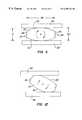
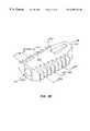
- FIG. 1Ais a perspective view of a permanently-implantable insert of the present invention
- FIG. 1Bis a perspective view of a temporarily-implantable insert of the present invention.
- FIG. 2is a side sectional elevation view of the insert of FIG. 1A;
- FIG. 3is a front elevation view of the insert of FIG. 1A;
- FIG. 4Ais a rear elevation view of the insert of FIG. 1A;
- FIG. 4Bis a rear sectional elevation view of an insert similar to that of FIG. 1A, but instead having its opposite vertebral supporting surfaces disposed at an angle to one another.
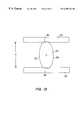
- FIG. 5is a top plan view of the insert of FIG. 1;
- FIG. 6is a schematic sectional side elevation view of an implant having an electronic transducer therein;
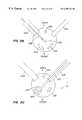
- FIG. 8is a perspective view of the insert of FIG. 1 as connected to a positioning rod;
- FIG. 9Ais a top plan view of the insert of FIG. 1 as received in an oval shaped cannula;
- FIG. 9Bis a end view taken along line 9 B— 9 B in FIG. 9 A.
- FIG. 10is a top plan view of 2 cannulae accessing a patient's spinal region
- FIG. 11is a perspective view of an insert as received between adjacent vertebrae
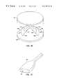
- FIG. 12is a perspective view illustrating camming action as the insert of FIGS. 9A and 9B is rotated;
- FIG. 15is a kit comprising an intervertebral insert according to the present invention and instructions for its use.
- FIG. 16is an exploded perspective view corresponding to FIG. 14 .
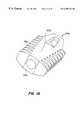
- FIG. 17is a perspective view of an oval coring device.
- FIG. 18is a side elevation view of another embodiment of the present insert.
- FIG. 19is a perspective view of the insert of FIG. 18 .
- FIG. 20is a perspective view of the insert of FIG. 18 .
- FIG. 21is an end elevation view of the insert of FIG. 18 .
- FIG. 22is a perspective view of the insert of FIG. 18 .
- FIG. 23is a sectional view taken along line 23 — 23 in FIG. 22 .
- FIGS. 24 a, 24 b and 24 care views corresponding to FIG. 23, but with but instead having its opposite vertebral supporting surfaces disposed at an angle to one another.
- FIG. 25shows a first step in inserting a quartet of inserts.
- FIG. 26shows a second step in inserting a quartet of inserts.
- FIG. 27shows a third step in inserting a quartet of inserts.
- FIG. 28shows a fourth step in inserting a quartet of inserts.
- FIG. 29shows a fifth step in inserting a quartet of inserts.
- FIG. 30shows a sixth step in inserting a quartet of inserts.
- FIG. 31shows a seventh step in inserting a quartet of inserts.
- outwardly facing convexly curved camming surfacea surface having a degree of curvature corresponding to an arc section defined by an angle in the range of 15 to 40 degrees, and most preferably about 20 degrees.
- racetrack-shapeda shape having two elongated parallel sides and two curved ends.
- the present inventioncomprises intervertebral inserts, methods and kits for separating and stabilizing adjacent vertebrae by camming apart the adjacent vertebrae with novel shaped intervertebral inserts having outwardly facing convexly curved camming surfaces disposed opposite one another. Both permanent and temporary intervertebral inserts are provided.
- FIGS. 1A, 2 , 3 , 4 A and 5A first embodiment of a permanent intervertebral insert 20 is best seen in FIGS. 1A, 2 , 3 , 4 A and 5 .
- Insert 20has a posterior end 24 and an anterior end 22 .
- a longitudinally extending central rotational axis 26extends between ends 22 and 24 .
- the length of insert 20i.e., the separation distance between ends 22 and 24
- the length of insert 20is in the range of 15 to 30 mm, and is most preferably about 25 mm.
- a pair of outwardly facing convexly curved camming surfaces 28 and 30are disposed on opposite sides of insert 20 at an angle to axis 26 as shown. Surfaces 28 and 30 are adapted to engage, and to separate by camming action, the opposed vertebral surfaces when insert 20 is placed between adjacent vertebrae and rotated into an anchored position, as will be described.
- outwardly facing convexly curved camming surfaces 28 and 30are selected to have a degree of curvature which facilitates camming with the degree of being neither too large (producing a more rounded insert which can only cam the vertebrae apart a short distance), nor too small (producing a flatter insert which requires greater force to cam into position). As shown in FIG.
- an appropriate degree of curvature of outwardly facing convex surfaces 28 and 30occurs when they are dimensioned to represent an arc segment defined by identical angles A 1 and A 2 which are in the range of 15 to 40 degrees, and is most preferably about 20 degrees.
- implant 19has surfaces 32 and 34 which are angled to one another such that outwardly facing convex surface 28 is dimensioned to represent an arc segment defined by an angle A 5 which is in the range of 15 to 40 degrees, and is most preferably about 20 degrees.
- Outwardly facing convex surface 30is somewhat smaller representing an arc segment defined by an angle A 6 .
- the angling of surfaces 32 a and 34 a with respect to one another as shown in FIG. 4Bassists in providing proper lordosis between the adjacent vertebrae when two inserts are positioned at right angles to one another in the intervertebral space, as will be described herein.
- opposite flattened vertebral support surfaces 32 and 34are disposed between outwardly facing convex surfaces 28 and 30 .
- opposite flattened surfaces 32 and 34are adapted to provide a flush contact against and thereby buttress adjacent separated vertebrae after insert 20 has been rotated into position. Selection of the optimal dimensions for opposite flattened surfaces 32 and 34 ensures that these surfaces are nether too wide nor too narrow. Should surfaces 32 and 34 be too wide, the size of the insert will be undesirably increased, making it more difficult to introduce into the intervertebral space.
- opposite flattened surfaces 32 and 34are preferably dimensioned to be in the range of 4 to 12 mm between outwardly facing convex surfaces 28 and 30 , depending upon the size of the insert.
- anchoring fins 36extend outwardly from each of opposite flattened surfaces 32 and 34 , and are preferably spaced apart in an anterior-posterior direction parallel to axis 26 .
- Fins 36may be textured on their projecting edges and expanded at their bases, (as shown in FIGS. 1 A and 5 ), so as to increase their ability to penetrate the vertebral endplates and enhance vertebral stability.
- fins 36may be barbed so as to increase their ability to remain firmly secured into the opposite adjacent vertebral surfaces.
- insert 20 and insert 19have a cross-sectional shape which is defined by a long axis 38 and a short axis 40 .
- Axes 38 and 40are perpendicular to one another and are also both perpendicular to rotational axis 26 .
- Long axis 38corresponds to the width of the insert and short axis 40 corresponds to the height of the insert.
- the height of the insertis in the range of 1.5 to 3 times the width of the insert. Most preferably, the width of the insert is two times greater than its height.
- the insertis ideally dimensioned to be inserted between adjacent vertebrae on its side, (preferably percutaneously through an oval-shaped cannula passage, and with minimal or no prior vertebral distraction by dedicated instrumentation), and then rotated into an anchored position therebetween, camming apart the adjacent vertebrae, as will be explained in conjunction with a preferred method.
- insert 20has preferred height to width dimensions, with the height being in the range of 1.5 to 3 times greater than said width of the insert.
- distance D 1 in FIG. 4A between vertex 29 of angle A 1 and rotational axis 26is preferably about 85% of the distance D 2 between vertex 29 and outer surface 28 .
- inserts 20 and 19have fenestrations 42 and 44 passing therethrough, with fenestration 42 passing generally perpendicular to outwardly facing convex surfaces 28 and 30 and fenestration 44 passing generally parallel to outwardly facing convex surfaces 28 and 30 .
- Fenestrations 42 and 44are adapted to receive bone graft material therein and thereby permit an opportunity for bone growth therethrough. Such bone growth therethrough assists in firmly holding the insert in an anchored position.
- fenestration 44permits bone growth therethrough in a vertical direction along the spinal axis and fenestration 42 permits bone growth therethrough in a direction perpendicular to the spinal axis when the insert is anchored into position between adjacent vertebral discs with its flattened surfaces 32 and 34 providing buttressing support against the vertebrae.
- Inserts 20 and 19can be made of any bio-compatible sterilizable material, including stainless steel, titanium, or carbon fiber composites.
- the insertis fabricated from a bio-absorbable material such that it will be absorbed into the patient's body. Suitable bio-absorbable materials include poly-L-lactic acid, polyglycolic acid and calcium triphosphates.
- a bioabsorbable inserthas the advantage that over time it will be absorbed by the body, such that the surrounding spinal and discal tissue will first have an opportunity to heal when the insert is fully supporting the spinal load through the adjacent vertebrae and maintaining the intervertebral disc spacing. Over time, as the insert is absorbed, a steadily increasing portion of the spinal load will be borne by the regenerated discal tissue and a steadily decreasing load will be borne by the insert itself.
- the insertwill promote disc re-generation by allowing the regenerated disc tissues to support progressively more of the spinal load as the disc tissues heal.
- the insertwill promote fusion by minimizing or eliminating normal motion for an extended period of time. Specifically, fusion will be promoted by the use of bone graft material and either a 2 to 3 year insert or a permanent insert.
- the speed of bio-absorptioncan be optimized per the desired use of the insert. Specifically, the use of collagen or polyglycolic acid will result in an insert which will be bio-absorbed in 6 to 12 months. Alternately, the use of poly-L-lactic acid will result in an insert which will be bio-absorbed in 2 to 3 years.
- a temporary placement insert 21is provided. Being removable, insert 21 is ideally suited for intra-operative insertion between adjacent vertebrae to provide working space, thereby temporarily increasing intervertebral spacing, such as when performing surgical procedures including a discectomy.
- Insert 21differs from inserts 20 and 19 in that anchoring fins 36 and fenestrations 42 and 44 (seen on inserts 20 and 19 ) are not seen on insert 21 . Lacking anchoring fins, the insert is more easily removable as it would not firmly anchor itself into the adjacent vertebrae. Moreover, fenestrations 42 and 44 are not required as no bone graft material need be introduced into a temporary implant, which is ideally removed at the end of a surgical procedure. Insert 21 preferably has a length (i.e., a separation distance between ends 22 and 24 ) in the range of 7 to 25 mm and most preferably 12 mm. Accordingly, insert is somewhat shorter than inserts 20 and 19 .
- insert 21will provide increased access for other tools to be received in the intervertebral space during procedures such as a discectomy.
- Fabrication of such a temporary-insertion insertcan be from a variety of sterilizable bio-compatible materials including stainless steel which has the advantage of reusability.
- an elongated positioning rod 48is preferably received into bore 25 in posterior surface 24 of insert 20 , as seen in FIG. 8 as used with insert 20 .
- Bore 25may be non-cylindrical or other shape such as hex-shaped to securely interlock with a non-symmetrical, hex-shaped, or keyed end 49 of rod 48 .
- Rotation of rod 48causes insert 20 to rotate about axis 26 , thereby causing outwardly facing camming surfaces 28 and 30 to engage, separate and stabilize adjacent vertebrae.
- rod 48is releasably secured to insert 20 by a ball detente mechanism such that insert 20 can conveniently be left in an anchored position between the adjacent vertebrae while rod 48 is detached and then removed.
- a torque wrench 37can be applied to rod 48 such hat the amount of torque necessary to cam apart the adjacent vertebral surfaces 50 and 52 can be measured. Such measurement can be used to determine the most appropriate size of insert to be used for any particular intervertebral application, as will be described in a preferred method herein.
- Torque wrench 37permits measurement of the torque necessary to rotate the insert into position.
- torque wrench 37may also include a lockout mechanism for shutting off the torque measurement capability of the wrench and eliminating play in the wrench, thereby permitting back and forth rotation of the insert within a narrow range of movement corresponding to a narrow range of movement of the torque wrench, (for example, plus or minus 15 degrees), such that the insert can be rocked back and forth into a firmly anchored position.
- a lockout mechanismwill preferably be engaged after the insert is first introduced and then rotated by 90 degrees to engage anchoring fins 36 into vertebrae 50 and 52 . Accordingly, the locking mechanism permits the insert to be easily rocked back and forth, causing fins 36 to be worked into an anchored position in vertebrae 50 and 52 while the torque wrench and rod can be moved through a greater arc of motion.
- Inserts 20 , 19 and 21are ideally adapted for delivery through a cannula having a non-symmetric cross-section which may be used for percutaneously introducing the insert with a minimal amount of tissue disruption.
- the non-symmetric cannulacan include an oval-shaped or racetrack-shaped cannula 54 having a lumen 55 shaped to slidingly mate with opposite outwardly facing convex camming surfaces 28 and 30 of insert 20 , thereby preventing insert 20 from rotating while in cannula 54 .
- the use of cannula 54permits insert 20 to be introduced percutaneously with minimal invasion and surrounding tissue damage as its flattened elongated cross-sectional shape permits it to be easily received between the adjacent vertebrae 50 and 52 .
- Insert 23can comprise any suitable insert and is not limited solely to intervertebral inserts and is also not limited to those intervertebral inserts corresponding to the above described geometries of inserts 20 , 19 and 21 .
- Insert 32has a body which is adapted to be implanted within or adjacent to bone 45 of a patient, wherein the insert has at least one surface 51 which will be loaded by bone motion against the implant. As shown in FIG. 6, insert 23 may simultaneously be placed adjacent to bones 45 and 47 with surfaces 51 and 53 being loaded by bone motion.
- insert 32can be configured as a dental prosthesis. Insert 32 is not limited in its application to positioning at any particular location in the body. Rather, all that is required is a periodic motion which tends to compress and/or stretch apart surfaces 51 and 53 of the insert. Repetitive cycling of loading on insert 32 operates to produce an electric current which, through wiring, can be directed to preferred locations in the body to promote bone growth.
- transducer 46may be embedded in various orthopedic or endodontic appliances such as bone and joint prostheses, plates, intermedullary rods, screws, external fixators, or any other appliances in which mechanical energy can be channeled to bone or peri-osseus tissue to stimulate bone formation and/or reduce bone loss.
- orthopedic or endodontic appliancessuch as bone and joint prostheses, plates, intermedullary rods, screws, external fixators, or any other appliances in which mechanical energy can be channeled to bone or peri-osseus tissue to stimulate bone formation and/or reduce bone loss.
- Transducer 46operates to generate an electric current when insert 23 is subjected to stress loading.
- Transducer 46can comprise a piezoelectric crystal which generates an electric current when insert 23 is subjected to normal repetitive loading through the patient's spine.
- transducer 46can comprise a battery which continuously generates an electric current.
- a wire 43operates to deliver the generated current to a preferred bone, bone graft or other area for bone formation.
- the body of insert 23may itself act as a ground for wire 43 .
- Transducer 46may be mechanically coupled to the surface of either or both of bones 51 or 53 , such as by anchoring fins, screws or bone cement. Transducer 46 operates to produce electrical voltage and current of a type and in an amount sufficient to induce osteogenesis in the bone.
- a preferred currentis in the range of 1 to 10 microamps, and most preferably about 2.5 microamps/cm 2 .
- FIG. 7illustrates one particular embodiment of an intervertebral application of orthopedic insert 23 .
- insert 23is implanted between adjacent vertebrae 45 and 47 .
- Bone graft materialis then introduced into space around the insert as well as within fenestration 41 such that wire 43 , (passing across fenestration 41 ), will apply current directly to the bone graft material, thereby promoting osteogenesis when vertebrae 45 and 47 repeatedly load surfaces 51 and 53 of insert 23 .
- FIGS. 11, 12 and 13illustrate a preferred method as carried out in conjunction with permanent insert 20 . This preferred method can also be carried out (with minor variations which will be explained) in conjunction with temporary insert 21 .
- insert 20is preferably inserted between vertebrae 50 and 52 with its short axis 40 being generally perpendicular to vertebrae 50 and 52 and its long axis 38 being generally parallel to vertebrae 50 and 52 . Having a small height in relation to its width, insert 20 can easily be inserted between the adjacent vertebrae with minimal or no prior distraction of the vertebrae, which would require highly invasive distractor tools being first inserted.
- the angling of surfaces 28 and 30 to axis 26results in a tapered shape of the insert from a narrow anterior end 22 to a wide posterior end 24 , which facilitates vertebral distraction when the insert is first introduced between the vertebrae, even prior to its rotation.
- narrow anterior end 22is introduced first, operating as a wedge to separate the adjacent vertebrae, as the insert is received therebetween.
- curved surfaces 28 and 30operate to smoothly cam apart vertebrae 50 and 52 (as seen in FIG. 12 ), and flattened vertebral support surfaces 32 and 34 become flush with the surfaces of vertebrae 50 and 52 , (as seen in FIG. 13 ), thereby providing a stable buttressing support between the adjacent vertebrae, as anchoring fins 36 protrude therein.
- the anchoring of insert 20is preferably accomplished by rotating the insert by approximately 90 degrees such that its anchoring fins 36 become embedded in the surface of vertebrae 50 and 52 , thereby holding insert 20 firmly in position.
- fins 36may be rotated back and forth by a small amount, such as 10 to 15 degrees, to cause fins 36 to firmly dig into the surfaces of the opposite vertebrae.
- insert 21which is temporarily-implanted during a surgical procedure, anchoring fins are not provided and therefore insert 21 is not anchored into position. Therefore, insert 21 can easily be removed by being rotated again by 90 degrees to be removed. Such subsequent rotation can either be in the same direction as shown in FIGS. 11 to 13 , or in the opposite direction.
- An advantage of rotating insert 21 in a direction opposite to that shown in FIG. 12 to remove the insertis that insertion and removal of the insert will not tend to cause lateral movement of one vertebrae with respect to the other.
- Temporary removable insert 21can thus be employed to jack apart vertebrae 50 and 52 such that the intervertebral space can be increased during surgical procedures such as a discectomy.
- a coring device 64Prior to introduction of the insert into cannula 54 , a coring device 64 can be inserted to cut through the annulus and remove osteophytes.
- An example of a coring deviceis provided in FIG. 17 .
- Coring device 64has a hollow end chamber 65 and is preferably punched directly into the material to be removed, and then drawn back out of the cannula with the cut out material being held in the coring device's hollow end chamber 65 .
- Inserts 20 , 19 and 21are preferably rotated into position, (and anchored into position in the case of insert 20 ) by an elongated positioning rod 48 which can be received into bore 25 in posterior surface 24 of insert 20 , as seen in FIG. 8 .
- Rotation of rod 48causes the insert to rotate about its axis 26 from the position seen in FIG. 11 through to the position seen in FIG. 13 .
- the optimal vertebral stabilization between any two adjacent vertebraewill be a function of both the initial and desired separation distance between the vertebrae.
- the initial separation distancewill itself be a function of the amount of tissue deterioration in the intervertebral space.
- the optimal vertebral stabilizationwill be a function of the condition of the discal tissues and the paraspinal tissues surrounding the intervertebral space. The greater the separation distance, the greater the likelihood of a fusion failure. On the other hand, if there is insufficient paraspinal tissue tension after placement, risk is increased that the vertebrae will move with respect to one another.
- a torque wrench 37can be applied to rod 48 such that the amount of torque necessary to cam apart the adjacent vertebral surfaces 50 and 52 can be measured.
- the optimal torque requiredwill be a function of many factors including initial intervertebral distance, ligament length and compliance and vertebral endplate load characteristics.
- the implantshould be removed and replaced with a smaller sized implant such that the vertebral surfaces are not damaged or distended too far, damaging surrounding tissue during insert implantation. Conversely, should the torque required to rotate the implant into position be too small, the implant should be removed and replaced with a larger sized implant such that the implant can provide proper vertebral separation and stabilization without being loose and thereby more likely to move out of its referred orientation.
- the present inventionalso provides a minimally invasive surgical method for percutaneously introducing an intervertebral insert into a patient's intervertebral space.
- This methodcan be carried out with any insert, including, but not limited to, inserts 20 , 19 , 21 or 23 , as described herein.
- FIGS. 9A and 9Bshow an example of the method as carried out with insert 20 .
- cannula 54is percutaneously introduced into a patient's back in a posterolateral approach.
- insert 20is introduced through cannula 54 into an intervertebral space between adjacent vertebrae 50 and 52 .
- the posterolateral approachis preferably in the range of an angle B of 35 to 90 degrees to an anterior-posterior axis 56 through the patient. Most preferably, angle B is about 45 degrees, such as when two inserts are implanted in the same intervertebral space at an angle to one another, as will be described in conjunction with an additional preferred method.
- the present angled posterolateral approachhas the important advantage that introduction of the implant into the intervertebral space avoids damage to the anterior and posterior longitudinal ligaments, ( 57 and 59 , respectively), the interspinous ligaments and the facet joint capsules.
- Cannula 54preferably has a non-symmetrical passage therethrough which can include an oval or racetrack passage which accommodates the dimensions of surfaces 28 and 30 of insert 20 such that insert 20 is prevented from rotating while it is in the cannula, enabling the insert to be positioned in the intervertebral space in the desired orientation.
- a non-symmetrical passage therethroughcan include an oval or racetrack passage which accommodates the dimensions of surfaces 28 and 30 of insert 20 such that insert 20 is prevented from rotating while it is in the cannula, enabling the insert to be positioned in the intervertebral space in the desired orientation.
- Another important advantage of cannula 54 having an oval or racetrack shapeis that it provides minimal tissue displacement and damage entering into the patient's body as compared to what would be the case if a larger round cannula were used.
- a method of positioning laterally-spaced apart first and second inserts in a patient's intervertebral spaceis provided.
- the insertsare oriented at an angle to one another so as to provide increased vertebral stability.
- This methodcan be carried out with any intervertebral insert, including, but not limited to, inserts 20 , 19 , 21 or 23 , as described herein.
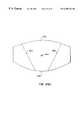
- FIGS. 10 and 14show an example of the method as carried out with a pair of inserts 19 such that the pair of inserts 19 a and 19 b are introduced between adjacent vertebrae 50 and 52 .
- a first insert 19 ais inserted between adjacent vertebrae 50 and 52 and then rotated and anchored into position.
- a second insert 19 bis inserted between adjacent vertebrae 50 and 52 and then rotated and anchored into position. The rotation of the second insert 19 b into position will provide additional support to the adjacent vertebrae 50 and 52 .
- inserts 19 a and 19 bare positioned side-by-side between the adjacent vertebrae with the inserts being positioned at an angle C to one another in a laterally spaced-apart orientation, as shown.
- the advantage of positioning inserts 19 a and 19 b at an angle to one anotheris the increased stability between vertebrae 50 and 52 caused by having rotational axes 26 a and 26 b disposed at angle C to one another.
- angle Cwill be in the range of 70 to 135 degrees, and most preferably be about 90 degrees. As can be seen in FIG.
- inserts 19 a and 19 bare therefore each preferably posterolaterally percutaneously introduced at an angle D being in the range of 35 to 90 degrees, and most preferably 45 degrees, from an anterior-posterior axis 56 passing through the patient's sagittal plane
- Anterior-posterior axis 56is perpendicular to spinal axis 58 .
- cannulae 54 a and 54 bare required to enter through the patient's back when separating and stabilizing vertebrae 50 and 52 by implanting inserts 19 a and 19 b.
- a very minimally invasive surgical techniqueis provided as compared to existing insert systems requiring open posterior techniques.
- cannulae 54 a and 54 bpreferably have non-symmetrical cross-sections, the potential for tissue damage is greatly reduced and the ability to position inserts 19 a and 19 b in the desired orientation within the intervertebral space is greatly enhanced. In this aspect of the method, prior disc distraction with dedicated instrumentation is not required.
- two posterolaterally introduced percutaneous cannulae 54 a and 54 bare used to introduce first and second inserts, 19 a and 19 B, respectively, as set forth above; however, insert 19 a is first introduced through cannula 54 a concurrently with an instrument 39 being introduced through cannula 54 b.
- Instrument 39can include a camera or arthroscope for viewing or recording the procedure, articulated forceps, shavers, osteophyte file, vertebral decorticator, oval coring device or bone graft introducer, which can be operated concurrently with the implantation of insert 19 a into the patient's intervertebral space.
- insert 19 ais anchored into position by a positioning rod which is then detached from the insert.
- Instrument 39is then removed from cannula 54 b and introduced into cannula 54 a to perform the same function while insert 19 b is introduced into the patient's intervertebral space through cannula 54 b and anchored into position by a positioning rod which is also then detached.
- inserts 19 a and 19 b positioned at right angles to one anotherare that surfaces 32 and 34 are angled with respect to one another such that they hold vertebrae 50 and 52 apart at a proper lordotic angle, preferably being about 10 degrees.
- inserts 19 a and 19 bare preferably positioned inverted to one another such that sides 30 oppose one another and sides 28 are positioned towards the rear of the intervertebral space, as shown.
- the present inventionalso includes a kit 60 , which can include intervertebral insert 20 .
- insert 20is shown in FIG. 15 .
- kit 60can alternatively include any other intervertebral insert including, but not limited to, inserts 21 and 23 instead or in addition to insert 20 .
- Kit 60further includes instructions for use 62 which may be in the form of literature accompanying the system, writing on packaging material, information stored on video or audio discs, electromagnetic data storage formats, or other data storage and presentation media. Instructions for use 62 set forth any of the preferred methods described herein.
- Kits of the present inventionmay optionally further include a positioning rod as described generally above.
- the positioning rodcan include, but is not limited to, rod 48 , as described.
- the kit componentswill usually be packaged together in a suitable container 61 , such as a pouch, box, tray, tube, or the like, typically being packaged in a sterile condition.
- vertebral supporting surfaces 32 a and 36 amay be disposed generally parallel to one another. However, as is shown in FIGS. 16 and 24 a, it is to be understood that vertebral supporting surfaces 32 a and 36 a may instead be disposed at an angle to one another, as shown, thereby assisting in providing proper intervertebral lordosis.
- angle of surfaces 32 a and 36 a with respect to one anothermay be constant from end 22 a to 22 b of insert 20 a.
- the angle of surfaces 32 a and 36 a with respect to one anothermay instead vary along the length of insert 20 a from end 22 a to end 24 a, also assisting in providing lordosis.
- angle of surfaces 32 and 36 with respect to one anothermay also vary along the length of insert 20 from end 22 to end 24 , also assisting in providing lordosis.
- FIGS. 25 to 31show sequential steps in inserting a quartet of inserts 200 , 210 , 220 and 230 , as follows.
- a first insert 200is inserted into a patient's intervertebral space and rotated into position by rod 202 received through cannula 204 .
- rod 202is removed and push rod 213 is inserted through cannula 214 , moving insert 200 in direction D 1 .
- FIG. 25show sequential steps in inserting a quartet of inserts 200 , 210 , 220 and 230 , as follows.
- rod 202is removed and push rod 213 is inserted through cannula 214 , moving insert 200 in direction D 1 .
- a second insert 210is inserted into a patient's intervertebral space and rotated into position by rod 212 received through cannula 214 .
- rod 212is removed and push rod 203 is inserted through cannula 204 , moving inserter 210 in direction D 2 .
- a third inserter 220is inserted into a patient's intervertebral space and rotated into position by rod 202 received through cannula 204 .
- rod 202is removed and push rod 213 is inserted through cannula 214 , moving insert 220 in direction D 1 .
- a fourth insert 230is positioned in the patient's intervertebral space using the above described methods.
- An optional temporary distractor 250may be positioned in the patient's intervertebral space during the above described procedure to increase the access for sliding inserts 200 , 210 , 220 and 230 into position.
- FIGS. 28 to 34showing a quartet of inserts 200 , 210 , 220 , and 230 inserted into the patient's intervertebral space is exemplary of the number of inserts which may be inserted into the intervertebral space. As such, more than four inserts, (for example 6, 8, 10 or more), may instead be used. In addition, odd numbers of inserts may be used as well, such as when dealing with non-symmetries in the patient's intervertebral space.
- Inserts 200 , 210 , 220 , and 230may comprise any of inserts 20 , 21 , 19 and 32 as described herein, however, it may be preferable to use inserts without fins so as to facilitate sliding movement of the inserts in respective D 1 and D 2 directions.
Landscapes
- Health & Medical Sciences (AREA)
- Engineering & Computer Science (AREA)
- Biomedical Technology (AREA)
- Orthopedic Medicine & Surgery (AREA)
- Transplantation (AREA)
- Neurology (AREA)
- Oral & Maxillofacial Surgery (AREA)
- Cardiology (AREA)
- Heart & Thoracic Surgery (AREA)
- Vascular Medicine (AREA)
- Life Sciences & Earth Sciences (AREA)
- Animal Behavior & Ethology (AREA)
- General Health & Medical Sciences (AREA)
- Public Health (AREA)
- Veterinary Medicine (AREA)
- Physical Education & Sports Medicine (AREA)
- Prostheses (AREA)
Abstract
Description
Claims (28)
Priority Applications (1)
| Application Number | Priority Date | Filing Date | Title |
|---|---|---|---|
| US09/320,161US6290724B1 (en) | 1998-05-27 | 1999-05-26 | Methods for separating and stabilizing adjacent vertebrae |
Applications Claiming Priority (5)
| Application Number | Priority Date | Filing Date | Title |
|---|---|---|---|
| US8694598P | 1998-05-27 | 1998-05-27 | |
| US11365198P | 1998-12-23 | 1998-12-23 | |
| US12066399P | 1999-02-19 | 1999-02-19 | |
| PCT/US1999/011686WO1999060957A1 (en) | 1998-05-27 | 1999-05-26 | Methods and apparatus for separating and stabilizing adjacent vertebrae |
| US09/320,161US6290724B1 (en) | 1998-05-27 | 1999-05-26 | Methods for separating and stabilizing adjacent vertebrae |
Publications (1)
| Publication Number | Publication Date |
|---|---|
| US6290724B1true US6290724B1 (en) | 2001-09-18 |
Family
ID=46149807
Family Applications (1)
| Application Number | Title | Priority Date | Filing Date |
|---|---|---|---|
| US09/320,161Expired - LifetimeUS6290724B1 (en) | 1998-05-27 | 1999-05-26 | Methods for separating and stabilizing adjacent vertebrae |
Country Status (2)
| Country | Link |
|---|---|
| US (1) | US6290724B1 (en) |
| WO (1) | WO1999060957A1 (en) |
Cited By (272)
| Publication number | Priority date | Publication date | Assignee | Title |
|---|---|---|---|---|
| US20020026191A1 (en)* | 2000-08-10 | 2002-02-28 | Dixon Robert A. | Cam action vertebral spreader |
| US20020165550A1 (en)* | 1999-10-21 | 2002-11-07 | George Frey | Devices and techniques for a posterior lateral disc space approach |
| US20030023306A1 (en)* | 2000-03-14 | 2003-01-30 | Mingyan Liu | Vertebral implant for promoting arthrodesis of the spine |
| US6537320B1 (en) | 1998-10-30 | 2003-03-25 | Gary K. Michelson | Self-broaching, rotatable, push-in interbody spinal fusion implant and method for deployment thereof |
| US6558424B2 (en)* | 2001-06-28 | 2003-05-06 | Depuy Acromed | Modular anatomic fusion device |
| US20030114931A1 (en)* | 2001-12-13 | 2003-06-19 | Lee Choon Sung | Spinal prosthetic implant and insertion instrument |
| US20030135275A1 (en)* | 2001-11-09 | 2003-07-17 | Javier Garcia | Instruments and methods for inserting a spinal implant |
| US20030233145A1 (en)* | 2002-03-11 | 2003-12-18 | Landry Michael E. | Instrumentation and procedure for implanting spinal implant devices |
| US20040030346A1 (en)* | 1999-10-21 | 2004-02-12 | George Frey | Devices and techniques for a posterior lateral disc space approach |
| US20040049283A1 (en)* | 2002-06-04 | 2004-03-11 | Tushar Patel | Medical implant and method of reducing back pain |
| US20040138749A1 (en)* | 2002-10-29 | 2004-07-15 | St. Francis Medical Technologies, Inc. | Artificial vertebral disk replacement implant with translating pivot point and method |
| US6764491B2 (en) | 1999-10-21 | 2004-07-20 | Sdgi Holdings, Inc. | Devices and techniques for a posterior lateral disc space approach |
| US20040153089A1 (en)* | 1995-03-27 | 2004-08-05 | Thomas Zdeblick | Methods and instruments for interbody fusion |
| US20040162616A1 (en)* | 2002-10-21 | 2004-08-19 | Simonton T. Andrew | Systems and techniques for restoring and maintaining intervertebral anatomy |
| US20040167628A1 (en)* | 2002-10-21 | 2004-08-26 | Foley Kevin T. | Systems and techniques for restoring and maintaining intervertebral anatomy |
| US20040176764A1 (en)* | 2003-03-03 | 2004-09-09 | Centerpulse Spine-Tech, Inc. | Apparatus and method for spinal distraction using a flip-up portal |
| US20040215189A1 (en)* | 2003-04-23 | 2004-10-28 | Kung-Chia Li | Pedicle augmenter for vertebral body reconstruction |
| US20040267365A1 (en)* | 2001-07-24 | 2004-12-30 | Maurizio Fornari | Device for intersomatic stabilization using a mini-invasive approach |
| US20050010292A1 (en)* | 2002-10-02 | 2005-01-13 | Carrasco Mauricio Rodolfo | Method for correcting a deformity in the spinal column and its corresponding implant |
| US20050027360A1 (en)* | 2003-08-01 | 2005-02-03 | Webb Scott A. | Spinal implant |
| US20050049704A1 (en)* | 2003-08-29 | 2005-03-03 | Jackson Roger P. | Convex spinal fusion interbody spacer |
| US20050222681A1 (en)* | 2002-06-17 | 2005-10-06 | Richard Richley | Devices and methods for minimally invasive treatment of degenerated spinal discs |
| WO2005055868A3 (en)* | 2003-12-02 | 2005-10-27 | St Francis Medical Tech Inc | Bioresorbable interspinous process implant for use with intervertebral disk remediation or replacement implants and procedures |
| US20050283161A1 (en)* | 2004-06-16 | 2005-12-22 | Sdgi Holdings, Inc. | Constant lift cam spreader |
| US20060074432A1 (en)* | 2004-10-06 | 2006-04-06 | Depuy Spine, Inc. | Modular medical tool and connector |
| US20060129238A1 (en)* | 2004-10-26 | 2006-06-15 | Adam Paltzer | Spinal stabilization device and methods |
| USD524443S1 (en) | 2005-11-04 | 2006-07-04 | Quantum Orthopedics, Inc. | Interbody fusion device |
| US20060217807A1 (en)* | 2005-03-28 | 2006-09-28 | Peterman Marc M | Spinal device including lateral approach |
| US20060217806A1 (en)* | 2005-03-28 | 2006-09-28 | Peterman Marc M | Spinal system and method including lateral approach |
| US20060235391A1 (en)* | 2005-03-08 | 2006-10-19 | Sutterlin Chester Iii | Facet joint stabilization |
| US20060247635A1 (en)* | 2003-08-05 | 2006-11-02 | Gordon Charles R | Dynamic posterior stabilization systems and methods of use |
| USD533277S1 (en) | 2005-11-04 | 2006-12-05 | Quantum Orthopedics, Inc. | Interbody fusion device |
| US20070050031A1 (en)* | 2005-08-23 | 2007-03-01 | Hamid Khosrowshahi | Spinal implant and implant inserter |
| US20070055374A1 (en)* | 2004-02-13 | 2007-03-08 | Copf, Franz, Jr. | Intervertebral implant and surgical method for spondylodesis of a lumbar vertebral column |
| US20070123985A1 (en)* | 2005-05-27 | 2007-05-31 | Spinecore, Inc. | Intervertebral disc and insertion methods therefor |
| US20070162129A1 (en)* | 2006-01-09 | 2007-07-12 | Edie Jason A | Adjustable insertion device for a vertebral implant |
| US20070161962A1 (en)* | 2006-01-09 | 2007-07-12 | Edie Jason A | Device and method for moving fill material to an implant |
| US20070173938A1 (en)* | 2006-01-26 | 2007-07-26 | Spinal Generations, Llc | Interbody cage system |
| US20070191859A1 (en)* | 2006-01-26 | 2007-08-16 | Sdgi Holding, Inc. | Surgical tool and method with an actuation mechanism for controlling reciprocation and locking of an anti-rotation member relative to an engagement member for facilitating positioning of an intervertebral device |
| US20070208347A1 (en)* | 1997-01-02 | 2007-09-06 | Zucherman James F | Spine distraction implant and method |
| US20070225813A1 (en)* | 2006-01-24 | 2007-09-27 | Timothy Haines | Dynamic spinal implants incorporating cartilage bearing graft material |
| US20070288091A1 (en)* | 2006-05-31 | 2007-12-13 | Braddock Danny H | Intervertebral lordatic adapter |
| US20080009861A1 (en)* | 2003-03-10 | 2008-01-10 | Stark John G | Sacroiliac joint immobilization |
| US7320707B2 (en) | 2003-11-05 | 2008-01-22 | St. Francis Medical Technologies, Inc. | Method of laterally inserting an artificial vertebral disk replacement implant with crossbar spacer |
| US20080172128A1 (en)* | 2007-01-16 | 2008-07-17 | Mi4Spine, Llc | Minimally Invasive Interbody Device Assembly |
| US20080234678A1 (en)* | 2007-03-20 | 2008-09-25 | Robert Gutierrez | Rod reducer |
| US20080269901A1 (en)* | 2007-04-27 | 2008-10-30 | Baynham Bret O | Spinal implant |
| US20080275506A1 (en)* | 2007-04-27 | 2008-11-06 | Baynham Bret O | Spinal implant |
| US7473256B2 (en) | 2003-10-23 | 2009-01-06 | Trans1 Inc. | Method and apparatus for spinal distraction |
| US20090024174A1 (en)* | 2007-07-17 | 2009-01-22 | Stark John G | Bone screws and particular applications to sacroiliac joint fusion |
| US7481840B2 (en) | 2004-09-29 | 2009-01-27 | Kyphon Sarl | Multi-piece artificial spinal disk replacement device with selectably positioning articulating element |
| US20090036895A1 (en)* | 2005-11-23 | 2009-02-05 | Trinity Orthopedics | Spinal distractor, compressor, and rod engaging system and method |
| US20090062928A1 (en)* | 2007-09-05 | 2009-03-05 | Mark Pitkin | In-bone implantable shaft for prosthetic joints or for direct skeletal attachment of external limb prostheses and method of its installation |
| US20090082775A1 (en)* | 2006-10-25 | 2009-03-26 | Moti Altarac | Spondylolisthesis reduction system and method |
| US20090082820A1 (en)* | 2004-03-09 | 2009-03-26 | Louie Fielding | Spinal implant and method for restricting spinal flexion |
| US20090099410A1 (en)* | 2005-06-09 | 2009-04-16 | De Marchena Eduardo | Papillary Muscle Attachment for Left Ventricular Reduction |
| US20090105758A1 (en)* | 2007-10-22 | 2009-04-23 | Gimbel Jonathan A | Dampener system for a posterior stabilization system with a variable length elongated member |
| US20090125047A1 (en)* | 2005-07-22 | 2009-05-14 | Joey Camia Reglos | Tissue splitter |
| US20090125032A1 (en)* | 2007-11-14 | 2009-05-14 | Gutierrez Robert C | Rod removal instrument |
| US20090138053A1 (en)* | 2007-09-25 | 2009-05-28 | Zyga Technology, Inc. | Method and apparatus for facet joint stabilization |
| US7544208B1 (en) | 2004-05-03 | 2009-06-09 | Theken Spine, Llc | Adjustable corpectomy apparatus |
| US20090164020A1 (en)* | 2007-11-28 | 2009-06-25 | Pioneer Surgical Technology, Inc. | Device for Securing an Implant to Tissue |
| US7575600B2 (en) | 2004-09-29 | 2009-08-18 | Kyphon Sarl | Artificial vertebral disk replacement implant with translating articulation contact surface and method |
| US20090216238A1 (en)* | 2008-02-27 | 2009-08-27 | Stark John G | Tools for performing less invasive orthopedic joint procedures |
| US20090240335A1 (en)* | 2008-03-24 | 2009-09-24 | Arcenio Gregory B | Expandable Devices for Emplacement in Body Parts and Methods Associated Therewith |
| US20090275953A1 (en)* | 2008-03-03 | 2009-11-05 | James Marino | Spool intervertebral distraction device and method |
| US20100004657A1 (en)* | 2008-01-18 | 2010-01-07 | Spinecore, Inc. | Instruments and methods for inserting artificial intervertebral implants |
| US7666227B2 (en) | 2005-08-16 | 2010-02-23 | Benvenue Medical, Inc. | Devices for limiting the movement of material introduced between layers of spinal tissue |
| US7670377B2 (en) | 2003-11-21 | 2010-03-02 | Kyphon Sarl | Laterally insertable artifical vertebral disk replacement implant with curved spacer |
| US7708778B2 (en) | 2003-08-05 | 2010-05-04 | Flexuspine, Inc. | Expandable articulating intervertebral implant with cam |
| US20100137922A1 (en)* | 2003-08-01 | 2010-06-03 | Hunt Margaret M | Variable angle spinal surgery instrument |
| US7749251B2 (en) | 2003-06-13 | 2010-07-06 | Aeolin, Llc | Method and apparatus for stabilization of facet joint |
| US20100198262A1 (en)* | 2009-01-30 | 2010-08-05 | Mckinley Laurence M | Axial offset bone fastener system |
| US20100204798A1 (en)* | 2005-10-21 | 2010-08-12 | Stryker Spine | System and method for fusion cage implantation |
| US7799056B2 (en) | 2007-12-31 | 2010-09-21 | Warsaw Orthopedic, Inc. | Bone fusion device and methods |
| US7837732B2 (en) | 2003-11-20 | 2010-11-23 | Warsaw Orthopedic, Inc. | Intervertebral body fusion cage with keels and implantation methods |
| US20110015747A1 (en)* | 2008-03-07 | 2011-01-20 | Mcmanus Joshua | Expandable interbody spacer device |
| US20110046736A1 (en)* | 2008-01-15 | 2011-02-24 | Henry Graf | Intervertebral stabilization assembly for arthrodesis, comprising an impaction cage body, and an ancillary device for implanting same |
| US7909869B2 (en) | 2003-08-05 | 2011-03-22 | Flexuspine, Inc. | Artificial spinal unit assemblies |
| US7918876B2 (en) | 2003-03-24 | 2011-04-05 | Theken Spine, Llc | Spinal implant adjustment device |
| US20110130836A1 (en)* | 2008-02-21 | 2011-06-02 | Lanx, Inc. | Compositions and Methods for Use of Scar Tissue in Repair of Weight Bearing Surfaces |
| US7959677B2 (en) | 2007-01-19 | 2011-06-14 | Flexuspine, Inc. | Artificial functional spinal unit system and method for use |
| US20110144469A1 (en)* | 2008-05-07 | 2011-06-16 | Patraicia Connolly | Bacterial/Cellular Recognition Impedance Algorithm |
| US20110166610A1 (en)* | 2009-08-07 | 2011-07-07 | Moti Altarac | Systems and methods for stabilization of bone structures, including thorocolumbar stabilization systems and methods |
| US7985231B2 (en) | 2007-12-31 | 2011-07-26 | Kyphon Sarl | Bone fusion device and methods |
| US8002837B2 (en) | 2006-05-19 | 2011-08-23 | Pioneer Surgical Technology | Spinal stabilization device and methods |
| US20110230968A1 (en)* | 2008-05-26 | 2011-09-22 | Michael Perisic | Intersomatic Cage |
| US8088163B1 (en) | 2008-02-06 | 2012-01-03 | Kleiner Jeffrey B | Tools and methods for spinal fusion |
| US8100972B1 (en) | 2007-07-02 | 2012-01-24 | Theken Spine, Llc | Spinal cage having deployable member |
| US20120029639A1 (en)* | 2010-07-29 | 2012-02-02 | Warsaw Orthopedic, Inc. | Interbody spinal implants and insertion techniques |
| US8118869B2 (en) | 2006-03-08 | 2012-02-21 | Flexuspine, Inc. | Dynamic interbody device |
| USD656610S1 (en) | 2009-02-06 | 2012-03-27 | Kleiner Jeffrey B | Spinal distraction instrument |
| WO2012040152A1 (en) | 2010-09-20 | 2012-03-29 | Jeffrey Kleiner | Fusion cage with combined biological delivery system |
| US20120078370A1 (en)* | 2010-08-31 | 2012-03-29 | James Stephen B | Spinal implants |
| US8157844B2 (en) | 2007-10-22 | 2012-04-17 | Flexuspine, Inc. | Dampener system for a posterior stabilization system with a variable length elongated member |
| US8162982B2 (en) | 2006-10-19 | 2012-04-24 | Simpirica Spine, Inc. | Methods and systems for constraint of multiple spine segments |
| US8162994B2 (en) | 2007-10-22 | 2012-04-24 | Flexuspine, Inc. | Posterior stabilization system with isolated, dual dampener systems |
| US8182514B2 (en) | 2007-10-22 | 2012-05-22 | Flexuspine, Inc. | Dampener system for a posterior stabilization system with a fixed length elongated member |
| CN101002703B (en)* | 2007-01-23 | 2012-06-13 | 成都军区昆明总医院 | Absorbable intrapyramidal stent |
| US8202299B2 (en) | 2008-03-19 | 2012-06-19 | Collabcom II, LLC | Interspinous implant, tools and methods of implanting |
| US8226690B2 (en) | 2005-07-22 | 2012-07-24 | The Board Of Trustees Of The Leland Stanford Junior University | Systems and methods for stabilization of bone structures |
| US8267965B2 (en) | 2007-10-22 | 2012-09-18 | Flexuspine, Inc. | Spinal stabilization systems with dynamic interbody devices |
| US8267969B2 (en) | 2004-10-20 | 2012-09-18 | Exactech, Inc. | Screw systems and methods for use in stabilization of bone structures |
| US8267997B2 (en) | 2007-11-12 | 2012-09-18 | Theken Spine, Llc | Vertebral interbody compression implant |
| US8292958B1 (en) | 2007-07-02 | 2012-10-23 | Theken Spine, Llc | Spinal cage having deployable member |
| WO2012145048A1 (en) | 2011-04-20 | 2012-10-26 | Spinewindow Llc | Method and apparatus for performing retro peritoneal dissection |
| US20120277864A1 (en)* | 2011-04-26 | 2012-11-01 | Warsaw Orthopedic, Inc. | Cannula assembly with non-circular profile and method of use |
| US8303601B2 (en) | 2006-06-07 | 2012-11-06 | Stryker Spine | Collet-activated distraction wedge inserter |
| US20120296428A1 (en)* | 2010-01-13 | 2012-11-22 | Jcbd, Llc | Systems for and methods of fusing a sacroiliac joint |
| WO2012162600A2 (en) | 2011-05-26 | 2012-11-29 | Strauch Eric | Surgical drape with separable elements |
| WO2012139022A3 (en)* | 2011-04-07 | 2012-12-06 | Kube Richard A | Interbody cage for spinal fusion and method of implanting interbody cages into spines |
| US20120316652A1 (en)* | 2007-05-17 | 2012-12-13 | Depuy Spine, Inc. | Self-Distracting Cage |
| US8366748B2 (en) | 2008-12-05 | 2013-02-05 | Kleiner Jeffrey | Apparatus and method of spinal implant and fusion |
| US8366773B2 (en) | 2005-08-16 | 2013-02-05 | Benvenue Medical, Inc. | Apparatus and method for treating bone |
| US20130046353A1 (en)* | 2011-08-17 | 2013-02-21 | Smith & Nephew, Inc. | Oval tunnel dilators |
| US8394125B2 (en) | 2009-07-24 | 2013-03-12 | Zyga Technology, Inc. | Systems and methods for facet joint treatment |
| WO2013075091A1 (en)* | 2011-11-17 | 2013-05-23 | Allosource | Multi-piece machine graft systems and methods |
| US8454660B2 (en) | 2006-10-19 | 2013-06-04 | Simpirica Spine, Inc. | Methods and systems for laterally stabilized constraint of spinous processes |
| US8454617B2 (en) | 2005-08-16 | 2013-06-04 | Benvenue Medical, Inc. | Devices for treating the spine |
| US8480745B2 (en) | 1997-08-26 | 2013-07-09 | Warsaw Orthopedic, Inc. | Spinal implant and cutting tool preparation accessory for mounting the implant |
| US8480715B2 (en) | 2007-05-22 | 2013-07-09 | Zimmer Spine, Inc. | Spinal implant system and method |
| US8518087B2 (en) | 2011-03-10 | 2013-08-27 | Interventional Spine, Inc. | Method and apparatus for minimally invasive insertion of intervertebral implants |
| US8523912B2 (en) | 2007-10-22 | 2013-09-03 | Flexuspine, Inc. | Posterior stabilization systems with shared, dual dampener systems |
| US8523904B2 (en) | 2004-03-09 | 2013-09-03 | The Board Of Trustees Of The Leland Stanford Junior University | Methods and systems for constraint of spinous processes with attachment |
| US8535327B2 (en) | 2009-03-17 | 2013-09-17 | Benvenue Medical, Inc. | Delivery apparatus for use with implantable medical devices |
| US8545562B1 (en) | 2007-07-02 | 2013-10-01 | Theken Spine, Llc | Deployable member for use with an intervertebral cage |
| US8562683B2 (en) | 2004-09-14 | 2013-10-22 | Aeolin Llc | System and method for spinal fusion |
| US8591583B2 (en) | 2005-08-16 | 2013-11-26 | Benvenue Medical, Inc. | Devices for treating the spine |
| US8597333B2 (en) | 2011-03-10 | 2013-12-03 | Interventional Spine, Inc. | Method and apparatus for minimally invasive insertion of intervertebral implants |
| US20140031941A1 (en)* | 2003-04-01 | 2014-01-30 | Warsaw Orthopedic, Inc. | Interbody spacer |
| US8663293B2 (en) | 2010-06-15 | 2014-03-04 | Zyga Technology, Inc. | Systems and methods for facet joint treatment |
| US8685031B2 (en) | 2009-09-18 | 2014-04-01 | Spinal Surgical Strategies, Llc | Bone graft delivery system |
| US20140114416A1 (en)* | 2012-10-19 | 2014-04-24 | Christian G. Zimmerman | Intervertibral disc cap and method of use |
| US8715351B1 (en) | 2012-11-29 | 2014-05-06 | Spine Wave, Inc. | Expandable interbody fusion device with graft chambers |
| US8814873B2 (en) | 2011-06-24 | 2014-08-26 | Benvenue Medical, Inc. | Devices and methods for treating bone tissue |
| US8828082B2 (en) | 2009-07-09 | 2014-09-09 | R Tree Innovations, Llc | Inter-body implant |
| US8828019B1 (en) | 2013-03-13 | 2014-09-09 | Spine Wave, Inc. | Inserter for expanding an expandable interbody fusion device |
| US20140277502A1 (en)* | 2013-03-15 | 2014-09-18 | NuTech Spine, Inc. | Anterior Lumbar Fusion Method and Device |
| US8864829B1 (en) | 2007-07-02 | 2014-10-21 | Theken Spine, Llc | Spinal cage having deployable member |
| US8900310B2 (en)* | 2012-04-05 | 2014-12-02 | Zimmer Spine, Inc. | Interbody spacer |
| US8900312B2 (en) | 2013-03-12 | 2014-12-02 | Spine Wave, Inc. | Expandable interbody fusion device with graft chambers |
| US8906028B2 (en) | 2009-09-18 | 2014-12-09 | Spinal Surgical Strategies, Llc | Bone graft delivery device and method of using the same |
| US8940051B2 (en) | 2011-03-25 | 2015-01-27 | Flexuspine, Inc. | Interbody device insertion systems and methods |
| USD723682S1 (en) | 2013-05-03 | 2015-03-03 | Spinal Surgical Strategies, Llc | Bone graft delivery tool |
| US8974496B2 (en) | 2007-08-30 | 2015-03-10 | Jeffrey Chun Wang | Interspinous implant, tools and methods of implanting |
| US20150142114A1 (en)* | 2013-11-21 | 2015-05-21 | Perumala Corporation | Intervertebral Disk Cage and Stabilizer |
| US9044341B2 (en) | 1998-08-20 | 2015-06-02 | Bonutti Skeletal Innovations Llc | Joint spacer |
| US9044333B2 (en) | 2007-07-27 | 2015-06-02 | R Tree Innovations, Llc | Inter-body implantation system and method |
| US9044284B2 (en) | 2010-09-29 | 2015-06-02 | Spinal Generations, Llc | Intervertebral insert system |
| US9044322B2 (en) | 1998-06-30 | 2015-06-02 | Bonutti Skeletal Innovations Llc | Method and apparatus for use in operating on a bone |
| US9060877B2 (en) | 2009-09-18 | 2015-06-23 | Spinal Surgical Strategies, Llc | Fusion cage with combined biological delivery system |
| US9078767B1 (en) | 2014-03-06 | 2015-07-14 | Spine Wave, Inc. | Expandable spinal interbody fusion device |
| US9095445B2 (en) | 2011-07-14 | 2015-08-04 | Warsaw Orthopedic, Inc. | Vertebral interbody spacer |
| US9173694B2 (en) | 2009-09-18 | 2015-11-03 | Spinal Surgical Strategies, Llc | Fusion cage with combined biological delivery system |
| US9186193B2 (en) | 2009-09-18 | 2015-11-17 | Spinal Surgical Strategies, Llc | Fusion cage with combined biological delivery system |
| WO2015187397A1 (en) | 2013-06-07 | 2015-12-10 | George Frey | Patient-matched apparatus and methods for performing surgical procedures |
| US9233006B2 (en) | 2010-06-15 | 2016-01-12 | Zyga Technology, Inc. | Systems and methods for facet joint treatment |
| US9247943B1 (en)* | 2009-02-06 | 2016-02-02 | Kleiner Intellectual Property, Llc | Devices and methods for preparing an intervertebral workspace |
| US9265623B2 (en) | 2014-03-06 | 2016-02-23 | Spine Wave, Inc. | Method of expanding a spinal interbody fusion device |
| USD750249S1 (en) | 2014-10-20 | 2016-02-23 | Spinal Surgical Strategies, Llc | Expandable fusion cage |
| US9277928B2 (en) | 2013-03-11 | 2016-03-08 | Interventional Spine, Inc. | Method and apparatus for minimally invasive insertion of intervertebral implants |
| US20160081820A1 (en)* | 2009-09-11 | 2016-03-24 | DePuy Synthes Products, Inc. | Minimally invasive intervertebral staple distraction devices |
| US9333090B2 (en) | 2010-01-13 | 2016-05-10 | Jcbd, Llc | Systems for and methods of fusing a sacroiliac joint |
| US9421109B2 (en) | 2010-01-13 | 2016-08-23 | Jcbd, Llc | Systems and methods of fusing a sacroiliac joint |
| US9439783B2 (en) | 2014-03-06 | 2016-09-13 | Spine Wave, Inc. | Inserter for expanding body tissue |
| US9445921B2 (en) | 2014-03-06 | 2016-09-20 | Spine Wave, Inc. | Device for expanding and supporting body tissue |
| US9451940B2 (en) | 2008-12-26 | 2016-09-27 | Pantheon Spinal, Llc | Method of retroperitoneal lateral insertion of spinal implants |
| US9492288B2 (en) | 2013-02-20 | 2016-11-15 | Flexuspine, Inc. | Expandable fusion device for positioning between adjacent vertebral bodies |
| US9517144B2 (en) | 2014-04-24 | 2016-12-13 | Exactech, Inc. | Limited profile intervertebral implant with incorporated fastening mechanism |
| US9526627B2 (en) | 2011-11-17 | 2016-12-27 | Exactech, Inc. | Expandable interbody device system and method |
| US20170020683A1 (en)* | 2003-04-21 | 2017-01-26 | Rsb Spine Llc | Bone plate stabilization system and method for its use |
| US9554909B2 (en) | 2012-07-20 | 2017-01-31 | Jcbd, Llc | Orthopedic anchoring system and methods |
| US9629729B2 (en) | 2009-09-18 | 2017-04-25 | Spinal Surgical Strategies, Llc | Biological delivery system with adaptable fusion cage interface |
| US9700356B2 (en) | 2013-07-30 | 2017-07-11 | Jcbd, Llc | Systems for and methods of fusing a sacroiliac joint |
| US9717539B2 (en) | 2013-07-30 | 2017-08-01 | Jcbd, Llc | Implants, systems, and methods for fusing a sacroiliac joint |
| US9717403B2 (en) | 2008-12-05 | 2017-08-01 | Jeffrey B. Kleiner | Method and apparatus for performing retro peritoneal dissection |
| US9757154B2 (en) | 2010-01-13 | 2017-09-12 | Jcbd, Llc | Systems and methods for fusing a sacroiliac joint and anchoring an orthopedic appliance |
| USD797290S1 (en) | 2015-10-19 | 2017-09-12 | Spinal Surgical Strategies, Llc | Bone graft delivery tool |
| US9788961B2 (en) | 2010-01-13 | 2017-10-17 | Jcbd, Llc | Sacroiliac joint implant system |
| US9788963B2 (en) | 2003-02-14 | 2017-10-17 | DePuy Synthes Products, Inc. | In-situ formed intervertebral fusion device and method |
| US9795396B2 (en) | 2010-01-13 | 2017-10-24 | Jcbd, Llc | Methods of fusing a sacroiliac joint |
| US9801546B2 (en) | 2014-05-27 | 2017-10-31 | Jcbd, Llc | Systems for and methods of diagnosing and treating a sacroiliac joint disorder |
| US9814598B2 (en) | 2013-03-14 | 2017-11-14 | Quandary Medical, Llc | Spinal implants and implantation system |
| US9826986B2 (en) | 2013-07-30 | 2017-11-28 | Jcbd, Llc | Systems for and methods of preparing a sacroiliac joint for fusion |
| US9833328B2 (en) | 2010-06-15 | 2017-12-05 | Zyga Technology | System and methods for facet joint treatment |
| US9883951B2 (en) | 2012-08-30 | 2018-02-06 | Interventional Spine, Inc. | Artificial disc |
| US9987024B2 (en) | 2010-06-29 | 2018-06-05 | Mighty Oak Medical, Inc. | Patient-matched apparatus and methods for performing surgical procedures |
| US9993353B2 (en) | 2013-03-14 | 2018-06-12 | DePuy Synthes Products, Inc. | Method and apparatus for minimally invasive insertion of intervertebral implants |
| US10028836B2 (en)* | 2016-01-26 | 2018-07-24 | The Regents Of The University Of Colorado | System and method of osteodistraction |
| EP3357459A1 (en) | 2017-02-03 | 2018-08-08 | Spinal Surgical Strategies, LLC | Bone graft delivery device with positioning handle |
| US10085783B2 (en) | 2013-03-14 | 2018-10-02 | Izi Medical Products, Llc | Devices and methods for treating bone tissue |
| US10245159B1 (en) | 2009-09-18 | 2019-04-02 | Spinal Surgical Strategies, Llc | Bone graft delivery system and method for using same |
| US10245087B2 (en) | 2013-03-15 | 2019-04-02 | Jcbd, Llc | Systems and methods for fusing a sacroiliac joint and anchoring an orthopedic appliance |
| US10292825B2 (en) | 2016-06-27 | 2019-05-21 | Globus Medical, Inc. | Intervertebral spacer with chamfered edges |
| US10292834B2 (en) | 2016-06-27 | 2019-05-21 | Globus Medical, Inc. | Intervertebral spacer with chamfered edges |
| US10321833B2 (en) | 2016-10-05 | 2019-06-18 | Innovative Surgical Solutions. | Neural locating method |
| US10335287B2 (en)* | 2014-01-14 | 2019-07-02 | Nuvasive, Inc. | Spinal fusion implant and related methods |
| USD853560S1 (en) | 2008-10-09 | 2019-07-09 | Nuvasive, Inc. | Spinal implant insertion device |
| US10342674B2 (en) | 2007-07-02 | 2019-07-09 | Theken Spine, Llc | Spinal cage having deployable member |
| US10363108B2 (en) | 2010-06-07 | 2019-07-30 | Creative Surgical Solutions, Llc | Surgical drape with separable elements |
| US10376209B2 (en) | 2013-09-20 | 2019-08-13 | Innovative Surgical Solutions, Llc | Neural locating method |
| US10376208B2 (en) | 2013-09-20 | 2019-08-13 | Innovative Surgical Solutions, Llc | Nerve mapping system |
| USD857893S1 (en) | 2017-10-26 | 2019-08-27 | Mighty Oak Medical, Inc. | Cortical surgical guide |
| USD858765S1 (en) | 2017-10-26 | 2019-09-03 | Mighty Oak Medical, Inc. | Cortical surgical guide |
| US10398565B2 (en) | 2014-04-24 | 2019-09-03 | Choice Spine, Llc | Limited profile intervertebral implant with incorporated fastening and locking mechanism |
| US10449002B2 (en) | 2013-09-20 | 2019-10-22 | Innovative Surgical Solutions, Llc | Method of mapping a nerve |
| US10478097B2 (en) | 2013-08-13 | 2019-11-19 | Innovative Surgical Solutions | Neural event detection |
| US10478096B2 (en) | 2013-08-13 | 2019-11-19 | Innovative Surgical Solutions. | Neural event detection |
| US10603055B2 (en) | 2017-09-15 | 2020-03-31 | Jcbd, Llc | Systems for and methods of preparing and fusing a sacroiliac joint |
| US10653454B2 (en) | 2007-07-13 | 2020-05-19 | Mighty Oak Medical, Inc. | Spinal fixation systems |
| US10716553B2 (en) | 2017-04-19 | 2020-07-21 | Pantheon Spinal, Llc | Spine surgery retractor system and related methods |
| US10743890B2 (en) | 2016-08-11 | 2020-08-18 | Mighty Oak Medical, Inc. | Drill apparatus and surgical fixation devices and methods for using the same |
| USD895111S1 (en) | 2018-06-04 | 2020-09-01 | Mighty Oak Medical, Inc. | Sacro-iliac guide |
| US10870002B2 (en) | 2018-10-12 | 2020-12-22 | DePuy Synthes Products, Inc. | Neuromuscular sensing device with multi-sensor array |
| US10869616B2 (en) | 2018-06-01 | 2020-12-22 | DePuy Synthes Products, Inc. | Neural event detection |
| US10888433B2 (en) | 2016-12-14 | 2021-01-12 | DePuy Synthes Products, Inc. | Intervertebral implant inserter and related methods |
| USD907771S1 (en) | 2017-10-09 | 2021-01-12 | Pioneer Surgical Technology, Inc. | Intervertebral implant |
| US10940016B2 (en) | 2017-07-05 | 2021-03-09 | Medos International Sarl | Expandable intervertebral fusion cage |
| US10966840B2 (en) | 2010-06-24 | 2021-04-06 | DePuy Synthes Products, Inc. | Enhanced cage insertion assembly |
| US10973656B2 (en) | 2009-09-18 | 2021-04-13 | Spinal Surgical Strategies, Inc. | Bone graft delivery system and method for using same |
| US10973652B2 (en) | 2007-06-26 | 2021-04-13 | DePuy Synthes Products, Inc. | Highly lordosed fusion cage |
| US11033403B2 (en) | 2017-07-10 | 2021-06-15 | Life Spine, Inc. | Expandable implant assembly |
| US11039889B2 (en) | 2010-06-29 | 2021-06-22 | Mighty Oak Medical, Inc. | Patient-matched apparatus and methods for performing surgical procedures |
| US11065132B2 (en) | 2014-03-06 | 2021-07-20 | Spine Wave, Inc. | Method of expanding a space between opposing tissue surfaces |
| US11103362B2 (en)* | 2013-03-13 | 2021-08-31 | Life Spine, Inc. | Expandable implant assembly |
| US11147682B2 (en) | 2017-09-08 | 2021-10-19 | Pioneer Surgical Technology, Inc. | Intervertebral implants, instruments, and methods |
| US11185382B2 (en) | 2017-08-31 | 2021-11-30 | Creative Surgical Solutions, Llc | Separable sterile drape with z-shaped folds |
| US11273050B2 (en) | 2006-12-07 | 2022-03-15 | DePuy Synthes Products, Inc. | Intervertebral implant |
| USD948717S1 (en) | 2018-06-04 | 2022-04-12 | Mighty Oak Medical, Inc. | Sacro-iliac guide |
| US11304818B2 (en) | 2013-03-13 | 2022-04-19 | Life Spine, Inc. | Expandable spinal interbody assembly |
| US11344424B2 (en) | 2017-06-14 | 2022-05-31 | Medos International Sarl | Expandable intervertebral implant and related methods |
| US11376073B2 (en) | 2010-06-29 | 2022-07-05 | Mighty Oak Medical Inc. | Patient-matched apparatus and methods for performing surgical procedures |
| US11382764B2 (en) | 2019-06-10 | 2022-07-12 | Life Spine, Inc. | Expandable implant assembly with compression features |
| US11399777B2 (en) | 2019-09-27 | 2022-08-02 | DePuy Synthes Products, Inc. | Intraoperative neural monitoring system and method |
| US11426286B2 (en) | 2020-03-06 | 2022-08-30 | Eit Emerging Implant Technologies Gmbh | Expandable intervertebral implant |
| US11426290B2 (en) | 2015-03-06 | 2022-08-30 | DePuy Synthes Products, Inc. | Expandable intervertebral implant, system, kit and method |
| US11446156B2 (en) | 2018-10-25 | 2022-09-20 | Medos International Sarl | Expandable intervertebral implant, inserter instrument, and related methods |
| US11446155B2 (en) | 2017-05-08 | 2022-09-20 | Medos International Sarl | Expandable cage |
| US11452607B2 (en) | 2010-10-11 | 2022-09-27 | DePuy Synthes Products, Inc. | Expandable interspinous process spacer implant |
| US11497619B2 (en) | 2013-03-07 | 2022-11-15 | DePuy Synthes Products, Inc. | Intervertebral implant |
| US11510788B2 (en) | 2016-06-28 | 2022-11-29 | Eit Emerging Implant Technologies Gmbh | Expandable, angularly adjustable intervertebral cages |
| US11596523B2 (en) | 2016-06-28 | 2023-03-07 | Eit Emerging Implant Technologies Gmbh | Expandable and angularly adjustable articulating intervertebral cages |
| US11602438B2 (en) | 2008-04-05 | 2023-03-14 | DePuy Synthes Products, Inc. | Expandable intervertebral implant |
| US11602439B2 (en) | 2020-04-16 | 2023-03-14 | Life Spine, Inc. | Expandable implant assembly |
| US11602440B2 (en) | 2020-06-25 | 2023-03-14 | Life Spine, Inc. | Expandable implant assembly |
| US11607321B2 (en) | 2009-12-10 | 2023-03-21 | DePuy Synthes Products, Inc. | Bellows-like expandable interbody fusion cage |
| US11612491B2 (en) | 2009-03-30 | 2023-03-28 | DePuy Synthes Products, Inc. | Zero profile spinal fusion cage |
| US11633254B2 (en) | 2018-06-04 | 2023-04-25 | Mighty Oak Medical, Inc. | Patient-matched apparatus for use in augmented reality assisted surgical procedures and methods for using the same |
| US11654033B2 (en) | 2010-06-29 | 2023-05-23 | DePuy Synthes Products, Inc. | Distractible intervertebral implant |
| US11666455B2 (en) | 2009-09-18 | 2023-06-06 | Spinal Surgical Strategies, Inc., A Nevada Corporation | Bone graft delivery devices, systems and kits |
| US11737881B2 (en) | 2008-01-17 | 2023-08-29 | DePuy Synthes Products, Inc. | Expandable intervertebral implant and associated method of manufacturing the same |
| US11752009B2 (en) | 2021-04-06 | 2023-09-12 | Medos International Sarl | Expandable intervertebral fusion cage |
| US20230346568A1 (en)* | 2022-04-27 | 2023-11-02 | Spark Spine LLC | Piezoelectric spinal implant and methods of making and using same |
| US11806197B2 (en) | 2010-06-29 | 2023-11-07 | Mighty Oak Medical, Inc. | Patient-matched apparatus for use in spine related surgical procedures and methods for using the same |
| US11813034B2 (en) | 2010-06-07 | 2023-11-14 | Creative Surgical Solutions, Llc | Surgical drape with separable elements |
| US11850160B2 (en) | 2021-03-26 | 2023-12-26 | Medos International Sarl | Expandable lordotic intervertebral fusion cage |
| US11857432B2 (en) | 2020-04-13 | 2024-01-02 | Life Spine, Inc. | Expandable implant assembly |
| US11896494B2 (en) | 2017-07-10 | 2024-02-13 | Life Spine, Inc. | Expandable implant assembly |
| US11911287B2 (en) | 2010-06-24 | 2024-02-27 | DePuy Synthes Products, Inc. | Lateral spondylolisthesis reduction cage |
| USRE49973E1 (en) | 2013-02-28 | 2024-05-21 | DePuy Synthes Products, Inc. | Expandable intervertebral implant, system, kit and method |
| US12016573B2 (en) | 2016-08-11 | 2024-06-25 | Mighty Oak Medical, Inc. | Drill apparatus and surgical fixation devices and methods for using the same |
| US12042395B2 (en) | 2019-06-11 | 2024-07-23 | Life Spine, Inc. | Expandable implant assembly |
| US12090064B2 (en) | 2022-03-01 | 2024-09-17 | Medos International Sarl | Stabilization members for expandable intervertebral implants, and related systems and methods |
| US12186201B2 (en) | 2007-07-02 | 2025-01-07 | Theken Spine, Llc | Spinal cage having deployable member |
| US12193948B2 (en) | 2013-03-13 | 2025-01-14 | Life Spine, Inc. | Expandable implant assembly |
| US12279972B2 (en) | 2008-05-22 | 2025-04-22 | Spinal Surgical Strategies, Inc. | Spinal fusion cage system with inserter |
| US12336917B2 (en) | 2020-05-15 | 2025-06-24 | Life Spine, Inc. | Steerable implant assembly |
| US12357413B2 (en) | 2010-06-29 | 2025-07-15 | Mighty Oak Medical, Inc. | Patient-matched apparatus for use in spine related surgical procedures and methods for using the same |
| US12364610B2 (en) | 2020-09-08 | 2025-07-22 | Life Spine, Inc. | Expandable implant with pivoting control assembly |
| US12370006B2 (en) | 2020-10-04 | 2025-07-29 | Creative Surgical Solutions, Llc | Surgical drape with separable elements |
| US12433649B2 (en) | 2019-02-13 | 2025-10-07 | The Trustees Of The University Of Pennsylvania | Systems and methods for a smart, implantable cranio-maxillo-facial distractor |
| US12440346B2 (en) | 2023-03-31 | 2025-10-14 | DePuy Synthes Products, Inc. | Expandable intervertebral implant |
Families Citing this family (25)
| Publication number | Priority date | Publication date | Assignee | Title |
|---|---|---|---|---|
| US7691145B2 (en) | 1999-10-22 | 2010-04-06 | Facet Solutions, Inc. | Prostheses, systems and methods for replacement of natural facet joints with artificial facet joint surfaces |
| ATE285207T1 (en) | 1999-10-22 | 2005-01-15 | Archus Orthopedics Inc | FACET ARTHROPLASTY DEVICES |
| US6974478B2 (en) | 1999-10-22 | 2005-12-13 | Archus Orthopedics, Inc. | Prostheses, systems and methods for replacement of natural facet joints with artificial facet joint surfaces |
| US7674293B2 (en) | 2004-04-22 | 2010-03-09 | Facet Solutions, Inc. | Crossbar spinal prosthesis having a modular design and related implantation methods |
| US8187303B2 (en) | 2004-04-22 | 2012-05-29 | Gmedelaware 2 Llc | Anti-rotation fixation element for spinal prostheses |
| ATE339164T1 (en)* | 2000-04-28 | 2006-10-15 | Perumala Corp | ROTATABLE AND LOCKING DISC STABILIZER AND DELIVERY DEVICE |
| US6599291B1 (en)* | 2000-10-20 | 2003-07-29 | Sdgi Holdings, Inc. | Methods and instruments for interbody surgical techniques |
| US20040230304A1 (en) | 2003-05-14 | 2004-11-18 | Archus Orthopedics Inc. | Prostheses, tools and methods for replacement of natural facet joints with artifical facet joint surfaces |
| US7608104B2 (en) | 2003-05-14 | 2009-10-27 | Archus Orthopedics, Inc. | Prostheses, tools and methods for replacement of natural facet joints with artifical facet joint surfaces |
| US7074238B2 (en) | 2003-07-08 | 2006-07-11 | Archus Orthopedics, Inc. | Prostheses, tools and methods for replacement of natural facet joints with artificial facet joint surfaces |
| US7588590B2 (en) | 2003-12-10 | 2009-09-15 | Facet Solutions, Inc | Spinal facet implant with spherical implant apposition surface and bone bed and methods of use |
| US20050131406A1 (en) | 2003-12-15 | 2005-06-16 | Archus Orthopedics, Inc. | Polyaxial adjustment of facet joint prostheses |
| US8333789B2 (en) | 2007-01-10 | 2012-12-18 | Gmedelaware 2 Llc | Facet joint replacement |
| US8562649B2 (en) | 2004-02-17 | 2013-10-22 | Gmedelaware 2 Llc | System and method for multiple level facet joint arthroplasty and fusion |
| US7051451B2 (en) | 2004-04-22 | 2006-05-30 | Archus Orthopedics, Inc. | Facet joint prosthesis measurement and implant tools |
| US7914556B2 (en) | 2005-03-02 | 2011-03-29 | Gmedelaware 2 Llc | Arthroplasty revision system and method |
| US7406775B2 (en) | 2004-04-22 | 2008-08-05 | Archus Orthopedics, Inc. | Implantable orthopedic device component selection instrument and methods |
| WO2006055186A2 (en) | 2004-10-25 | 2006-05-26 | Archus Orthopedics, Inc. | Spinal prosthesis having a modular design |
| US7507242B2 (en) | 2004-06-02 | 2009-03-24 | Facet Solutions | Surgical measurement and resection framework |
| AU2005277363A1 (en) | 2004-08-18 | 2006-03-02 | Fsi Acquisition Sub, Llc | Adjacent level facet arthroplasty devices, spine stabilization systems, and methods |
| US8496686B2 (en) | 2005-03-22 | 2013-07-30 | Gmedelaware 2 Llc | Minimally invasive spine restoration systems, devices, methods and kits |
| US8702755B2 (en) | 2006-08-11 | 2014-04-22 | Gmedelaware 2 Llc | Angled washer polyaxial connection for dynamic spine prosthesis |
| CA2675037A1 (en) | 2007-01-10 | 2008-07-17 | Facet Solutions, Inc. | Taper-locking fixation system |
| FR2926213B1 (en)* | 2008-01-15 | 2010-02-05 | Henry Graf | INTERVERTEBRAL STABILIZATION ASSEMBLY COMPRISING AN IMPACTION CAGE BODY AND ITS ANCILLARY INSTALLATION |
| FR2936407A1 (en)* | 2008-09-30 | 2010-04-02 | Henry Graf | Prosthesis assembly for accompanying intervertebral movement, has nose rotated to simultaneously induce opening of intervertebral space and displacement of cage body similar to that of cam, when nose is introduced into intervertebral space |
Citations (94)
| Publication number | Priority date | Publication date | Assignee | Title |
|---|---|---|---|---|
| US3745995A (en) | 1969-04-10 | 1973-07-17 | W Kraus | Apparatus and method for aiding formation of bone forming material |
| US3848601A (en) | 1972-06-14 | 1974-11-19 | G Ma | Method for interbody fusion of the spine |
| US4026304A (en) | 1972-04-12 | 1977-05-31 | Hydro Med Sciences Inc. | Bone generating method and device |
| US4781591A (en) | 1987-04-06 | 1988-11-01 | Allen James P | Endosteal implant and method for performing implantation thereof |
| US4877020A (en) | 1984-11-30 | 1989-10-31 | Vich Jose M O | Apparatus for bone graft |
| EP0369603A1 (en) | 1988-10-17 | 1990-05-23 | Surgical Dynamics, Inc. | Fusion cage for bone joints |
| US4932975A (en) | 1989-10-16 | 1990-06-12 | Vanderbilt University | Vertebral prosthesis |
| CA2015507A1 (en) | 1989-07-06 | 1991-01-06 | Stephen D. Kuslich | Spinal implant |
| WO1991006261A1 (en) | 1989-11-06 | 1991-05-16 | Surgical Dynamics, Inc. | Surgical method and apparatus for fusing adjacent bone structures |
| US5055104A (en) | 1989-11-06 | 1991-10-08 | Surgical Dynamics, Inc. | Surgically implanting threaded fusion cages between adjacent low-back vertebrae by an anterior approach |
| US5062845A (en) | 1989-05-10 | 1991-11-05 | Spine-Tech, Inc. | Method of making an intervertebral reamer |
| US5133717A (en) | 1990-02-08 | 1992-07-28 | Societe De Fabrication De Material Orthopedique Sofamor | Sacral support saddle for a spinal osteosynthesis device |
| EP0517030A2 (en) | 1991-06-04 | 1992-12-09 | MAN Ceramics GmbH | Vertebral implant |
| US5171278A (en) | 1991-02-22 | 1992-12-15 | Madhavan Pisharodi | Middle expandable intervertebral disk implants |
| US5290494A (en) | 1990-03-05 | 1994-03-01 | Board Of Regents, The University Of Texas System | Process of making a resorbable implantation device |
| WO1994004100A1 (en) | 1992-08-24 | 1994-03-03 | Societe De Fabrication De Materiel Orthopedique - Sofamor | Intervertebral disk prosthesis |
| US5300076A (en) | 1991-10-11 | 1994-04-05 | Societe De Fabrication De Materiel Orthopedique-Sofamore | Percutaneous bone screw for supporting a stereotaxy frame |
| US5304210A (en) | 1992-01-28 | 1994-04-19 | Amei Technologies Inc. | Apparatus for distributed bone growth stimulation |
| US5306309A (en) | 1992-05-04 | 1994-04-26 | Calcitek, Inc. | Spinal disk implant and implantation kit |
| US5306307A (en) | 1991-07-22 | 1994-04-26 | Calcitek, Inc. | Spinal disk implant |
| WO1994010928A1 (en) | 1992-11-13 | 1994-05-26 | Sofamor, S.N.C. | Pedicular screw and posterior spinal instrumentation |
| US5334205A (en) | 1993-06-30 | 1994-08-02 | The United States Of America As Represented By The Secretary Of The Air Force | Sacroiliac joint fixation guide |
| US5336223A (en) | 1993-02-04 | 1994-08-09 | Rogers Charles L | Telescoping spinal fixator |
| US5364400A (en) | 1992-02-14 | 1994-11-15 | American Cyanamid Co. | Interference implant |
| WO1995001810A1 (en) | 1993-07-07 | 1995-01-19 | Smith & Nephew Plc | Implantable prosthesis, kit and device for manufacturing the same |
| US5395372A (en) | 1993-09-07 | 1995-03-07 | Danek Medical, Inc. | Spinal strut graft holding staple |
| US5397363A (en) | 1992-08-11 | 1995-03-14 | Gelbard; Steven D. | Spinal stabilization implant system |
| US5413602A (en) | 1991-09-30 | 1995-05-09 | Howmedica Gmbh | Vertebral body spacer device |
| US5425772A (en) | 1993-09-20 | 1995-06-20 | Brantigan; John W. | Prosthetic implant for intervertebral spinal fusion |
| US5431658A (en)* | 1994-02-14 | 1995-07-11 | Moskovich; Ronald | Facilitator for vertebrae grafts and prostheses |
| US5443515A (en) | 1994-01-26 | 1995-08-22 | Implex Corporation | Vertebral body prosthetic implant with slidably positionable stabilizing member |
| US5443514A (en) | 1993-10-01 | 1995-08-22 | Acromed Corporation | Method for using spinal implants |
| US5445639A (en) | 1989-05-10 | 1995-08-29 | Spine-Tech, Inc. | Intervertebral reamer construction |
| US5454811A (en) | 1993-11-08 | 1995-10-03 | Smith & Nephew Dyonics, Inc. | Cam lock orthopedic fixation screw and method |
| US5458638A (en) | 1989-07-06 | 1995-10-17 | Spine-Tech, Inc. | Non-threaded spinal implant |
| WO1996008205A1 (en) | 1994-09-15 | 1996-03-21 | Surgical Dynamics, Inc. | Conically-shaped anterior fusion cage and method of implantation |
| EP0706876A1 (en) | 1994-10-14 | 1996-04-17 | Acromed Corporation | Composite structure and method of forming same |
| US5522899A (en) | 1988-06-28 | 1996-06-04 | Sofamor Danek Properties, Inc. | Artificial spinal fusion implants |
| US5522879A (en) | 1991-11-12 | 1996-06-04 | Ethicon, Inc. | Piezoelectric biomedical device |
| US5524624A (en) | 1994-05-05 | 1996-06-11 | Amei Technologies Inc. | Apparatus and method for stimulating tissue growth with ultrasound |
| WO1996017564A1 (en) | 1994-12-09 | 1996-06-13 | Sofamor Danek Group, Inc. | Adjustable vertebral body replacement |
| EP0716840A2 (en) | 1994-12-12 | 1996-06-19 | Surgical Dynamics, Inc. | Conically-shaped fusion cage and method of implantation |
| US5534030A (en) | 1993-02-09 | 1996-07-09 | Acromed Corporation | Spine disc |
| US5540688A (en) | 1991-05-30 | 1996-07-30 | Societe "Psi" | Intervertebral stabilization device incorporating dampers |
| US5562736A (en) | 1994-10-17 | 1996-10-08 | Raymedica, Inc. | Method for surgical implantation of a prosthetic spinal disc nucleus |
| US5565005A (en) | 1992-02-20 | 1996-10-15 | Amei Technologies Inc. | Implantable growth tissue stimulator and method operation |
| EP0737448A1 (en) | 1995-04-10 | 1996-10-16 | Sofamor Danek Group, Inc. | Transverse connection for spinal jobs |
| US5571192A (en) | 1994-07-02 | 1996-11-05 | Heinrich Ulrich | Prosthetic vertebral implant |
| WO1996041582A1 (en) | 1995-06-13 | 1996-12-27 | Societe De Fabrication De Materiel Orthopedique En Abrege - Sofamor | Implant for surgically treating a vertebral isthmic fracture |
| US5593409A (en) | 1988-06-13 | 1997-01-14 | Sofamor Danek Group, Inc. | Interbody spinal fusion implants |
| US5609636A (en) | 1994-05-23 | 1997-03-11 | Spine-Tech, Inc. | Spinal implant |
| US5611800A (en) | 1994-02-15 | 1997-03-18 | Alphatec Manufacturing, Inc. | Spinal fixation system |
| WO1997020513A1 (en) | 1995-12-07 | 1997-06-12 | Aesculap Ag | Orthopaedic fixing system |
| US5645598A (en) | 1996-01-16 | 1997-07-08 | Smith & Nephew, Inc. | Spinal fusion device with porous material |
| US5653761A (en) | 1994-03-18 | 1997-08-05 | Pisharodi; Madhavan | Method of lumbar intervertebral disk stabilization |
| US5653762A (en) | 1994-03-18 | 1997-08-05 | Pisharodi; Madhavan | Method of stabilizing adjacent vertebrae with rotating, lockable, middle-expanded intervertebral disk stabilizer |
| US5658336A (en) | 1994-03-18 | 1997-08-19 | Pisharodi; Madhavan | Rotating, locking, middle-expanded intervertebral disk stabilizer |
| US5665122A (en) | 1995-01-31 | 1997-09-09 | Kambin; Parviz | Expandable intervertebral cage and surgical method |
| WO1997033525A1 (en) | 1996-03-14 | 1997-09-18 | Surgical Dynamics, Inc. | Apparatus and method for implant insertion |
| US5669909A (en) | 1995-03-27 | 1997-09-23 | Danek Medical, Inc. | Interbody fusion device and method for restoration of normal spinal anatomy |
| EP0796593A2 (en) | 1996-03-14 | 1997-09-24 | Surgical Dynamics, Inc. | Method and instrumentation for surgical implant insertion |
| US5676703A (en) | 1994-05-11 | 1997-10-14 | Gelbard; Steven D. | Spinal stabilization implant system |
| WO1997037620A1 (en) | 1996-04-03 | 1997-10-16 | Scient'x S.A.R.L. | Intersomatic setting and fusion system |
| US5683394A (en) | 1995-09-29 | 1997-11-04 | Advanced Spine Fixation Systems, Inc. | Fusion mass constrainer |
| US5690629A (en) | 1996-04-24 | 1997-11-25 | Acromed Corporation | Apparatus for maintaining vertebrae of a spinal column in a desired spatial relationship |
| EP0809975A2 (en) | 1996-05-31 | 1997-12-03 | Acromed Corporation | An apparatus comprising a plate and a fastener for connecting the plate to a bone portion |
| EP0809974A2 (en) | 1996-05-31 | 1997-12-03 | Acromed Corporation | An apparatus for retaining bone portions in a desired spatial relationship |
| EP0811356A2 (en) | 1996-06-05 | 1997-12-10 | Acromed Corporation | Spinal column retaining apparatus |
| US5700291A (en) | 1993-02-10 | 1997-12-23 | Spine-Tech, Inc. | Laparoscopic spinal stabilization method |
| US5700264A (en) | 1996-07-01 | 1997-12-23 | Zucherman; James F. | Apparatus and method for preparing a site for an interbody fusion implant |
| US5700292A (en) | 1992-11-09 | 1997-12-23 | Hospital For Joint Diseases | Spinal stabilization system and method |
| US5702449A (en) | 1995-06-07 | 1997-12-30 | Danek Medical, Inc. | Reinforced porous spinal implants |
| US5702451A (en) | 1995-02-14 | 1997-12-30 | Biedermann; Lutz | Space holder, in particular for a vertebra or an intervertebral disk |
| US5711957A (en) | 1993-05-13 | 1998-01-27 | Inoteb | Use of a porous calcium carbonate based material as support of a growth factor in the preparation of a bioabsorbable implant |
| US5716415A (en) | 1993-10-01 | 1998-02-10 | Acromed Corporation | Spinal implant |
| US5720751A (en)* | 1996-11-27 | 1998-02-24 | Jackson; Roger P. | Tools for use in seating spinal rods in open ended implants |
| US5766252A (en) | 1995-01-24 | 1998-06-16 | Osteonics Corp. | Interbody spinal prosthetic implant and method |
| US5772661A (en) | 1988-06-13 | 1998-06-30 | Michelson; Gary Karlin | Methods and instrumentation for the surgical correction of human thoracic and lumbar spinal disease from the antero-lateral aspect of the spine |
| US5797909A (en) | 1988-06-13 | 1998-08-25 | Michelson; Gary Karlin | Apparatus for inserting spinal implants |
| US5800550A (en) | 1996-03-13 | 1998-09-01 | Sertich; Mario M. | Interbody fusion cage |
| US5800549A (en)* | 1997-04-30 | 1998-09-01 | Howmedica Inc. | Method and apparatus for injecting an elastic spinal implant |
| US5814084A (en) | 1996-01-16 | 1998-09-29 | University Of Florida Tissue Bank, Inc. | Diaphysial cortical dowel |
| EP0880938A1 (en) | 1997-05-30 | 1998-12-02 | United States Surgical Corporation | Instrumentation for implant insertion |
| US5888224A (en) | 1993-09-21 | 1999-03-30 | Synthesis (U.S.A.) | Implant for intervertebral space |
| US5893890A (en) | 1994-03-18 | 1999-04-13 | Perumala Corporation | Rotating, locking intervertebral disk stabilizer and applicator |
| US5904719A (en)* | 1997-07-24 | 1999-05-18 | Techsys Medical, Llc | Interbody fusion device having partial circular section cross-sectional segments |
| US5910315A (en)* | 1997-07-18 | 1999-06-08 | Stevenson; Sharon | Allograft tissue material for filling spinal fusion cages or related surgical spaces |
| US5968098A (en) | 1996-10-22 | 1999-10-19 | Surgical Dynamics, Inc. | Apparatus for fusing adjacent bone structures |
| US6004326A (en) | 1997-09-10 | 1999-12-21 | United States Surgical | Method and instrumentation for implant insertion |
| US6015436A (en) | 1996-06-07 | 2000-01-18 | Heinrich Ulrich | Implant for filling a space between vertebrae |
| US6033405A (en) | 1994-09-15 | 2000-03-07 | Surgical Dynamics, Inc. | Apparatus and method for implant insertion |
| US6042582A (en) | 1997-05-20 | 2000-03-28 | Ray; Charles D. | Instrumentation and method for facilitating insertion of spinal implant |
| US6063088A (en) | 1997-03-24 | 2000-05-16 | United States Surgical Corporation | Method and instrumentation for implant insertion |
| US6120506A (en) | 1997-03-06 | 2000-09-19 | Sulzer Spine-Tech Inc. | Lordotic spinal implant |
- 1999
- 1999-05-26USUS09/320,161patent/US6290724B1/ennot_activeExpired - Lifetime
- 1999-05-26WOPCT/US1999/011686patent/WO1999060957A1/enactiveApplication Filing
Patent Citations (107)
| Publication number | Priority date | Publication date | Assignee | Title |
|---|---|---|---|---|
| US3745995A (en) | 1969-04-10 | 1973-07-17 | W Kraus | Apparatus and method for aiding formation of bone forming material |
| US4026304A (en) | 1972-04-12 | 1977-05-31 | Hydro Med Sciences Inc. | Bone generating method and device |
| US3848601A (en) | 1972-06-14 | 1974-11-19 | G Ma | Method for interbody fusion of the spine |
| US4877020A (en) | 1984-11-30 | 1989-10-31 | Vich Jose M O | Apparatus for bone graft |
| US4781591A (en) | 1987-04-06 | 1988-11-01 | Allen James P | Endosteal implant and method for performing implantation thereof |
| US5593409A (en) | 1988-06-13 | 1997-01-14 | Sofamor Danek Group, Inc. | Interbody spinal fusion implants |
| US5797909A (en) | 1988-06-13 | 1998-08-25 | Michelson; Gary Karlin | Apparatus for inserting spinal implants |
| US5785710A (en) | 1988-06-13 | 1998-07-28 | Sofamor Danek Group, Inc. | Interbody spinal fusion implants |
| US5772661A (en) | 1988-06-13 | 1998-06-30 | Michelson; Gary Karlin | Methods and instrumentation for the surgical correction of human thoracic and lumbar spinal disease from the antero-lateral aspect of the spine |
| US5522899A (en) | 1988-06-28 | 1996-06-04 | Sofamor Danek Properties, Inc. | Artificial spinal fusion implants |
| US5026373A (en) | 1988-10-17 | 1991-06-25 | Surgical Dynamics, Inc. | Surgical method and apparatus for fusing adjacent bone structures |
| US4961740B1 (en) | 1988-10-17 | 1997-01-14 | Surgical Dynamics Inc | V-thread fusion cage and method of fusing a bone joint |
| US4961740A (en) | 1988-10-17 | 1990-10-09 | Surgical Dynamics, Inc. | V-thread fusion cage and method of fusing a bone joint |
| EP0369603A1 (en) | 1988-10-17 | 1990-05-23 | Surgical Dynamics, Inc. | Fusion cage for bone joints |
| US5062845A (en) | 1989-05-10 | 1991-11-05 | Spine-Tech, Inc. | Method of making an intervertebral reamer |
| US5445639A (en) | 1989-05-10 | 1995-08-29 | Spine-Tech, Inc. | Intervertebral reamer construction |
| US5489308A (en) | 1989-07-06 | 1996-02-06 | Spine-Tech, Inc. | Spinal implant |
| US5458638A (en) | 1989-07-06 | 1995-10-17 | Spine-Tech, Inc. | Non-threaded spinal implant |
| CA2015507A1 (en) | 1989-07-06 | 1991-01-06 | Stephen D. Kuslich | Spinal implant |
| US4932975A (en) | 1989-10-16 | 1990-06-12 | Vanderbilt University | Vertebral prosthesis |
| WO1991006261A1 (en) | 1989-11-06 | 1991-05-16 | Surgical Dynamics, Inc. | Surgical method and apparatus for fusing adjacent bone structures |
| US5055104A (en) | 1989-11-06 | 1991-10-08 | Surgical Dynamics, Inc. | Surgically implanting threaded fusion cages between adjacent low-back vertebrae by an anterior approach |
| US5133717A (en) | 1990-02-08 | 1992-07-28 | Societe De Fabrication De Material Orthopedique Sofamor | Sacral support saddle for a spinal osteosynthesis device |
| US5290494A (en) | 1990-03-05 | 1994-03-01 | Board Of Regents, The University Of Texas System | Process of making a resorbable implantation device |
| US5171278A (en) | 1991-02-22 | 1992-12-15 | Madhavan Pisharodi | Middle expandable intervertebral disk implants |
| US5540688A (en) | 1991-05-30 | 1996-07-30 | Societe "Psi" | Intervertebral stabilization device incorporating dampers |
| EP0517030A2 (en) | 1991-06-04 | 1992-12-09 | MAN Ceramics GmbH | Vertebral implant |
| US5306307A (en) | 1991-07-22 | 1994-04-26 | Calcitek, Inc. | Spinal disk implant |
| US5413602A (en) | 1991-09-30 | 1995-05-09 | Howmedica Gmbh | Vertebral body spacer device |
| US5300076A (en) | 1991-10-11 | 1994-04-05 | Societe De Fabrication De Materiel Orthopedique-Sofamore | Percutaneous bone screw for supporting a stereotaxy frame |
| US5522879A (en) | 1991-11-12 | 1996-06-04 | Ethicon, Inc. | Piezoelectric biomedical device |
| US5304210A (en) | 1992-01-28 | 1994-04-19 | Amei Technologies Inc. | Apparatus for distributed bone growth stimulation |
| US5364400A (en) | 1992-02-14 | 1994-11-15 | American Cyanamid Co. | Interference implant |
| US5565005A (en) | 1992-02-20 | 1996-10-15 | Amei Technologies Inc. | Implantable growth tissue stimulator and method operation |
| US5306309A (en) | 1992-05-04 | 1994-04-26 | Calcitek, Inc. | Spinal disk implant and implantation kit |
| US5683464A (en) | 1992-05-04 | 1997-11-04 | Sulzer Calcitek Inc. | Spinal disk implantation kit |
| US5397363A (en) | 1992-08-11 | 1995-03-14 | Gelbard; Steven D. | Spinal stabilization implant system |
| WO1994004100A1 (en) | 1992-08-24 | 1994-03-03 | Societe De Fabrication De Materiel Orthopedique - Sofamor | Intervertebral disk prosthesis |
| US5700292A (en) | 1992-11-09 | 1997-12-23 | Hospital For Joint Diseases | Spinal stabilization system and method |
| WO1994010928A1 (en) | 1992-11-13 | 1994-05-26 | Sofamor, S.N.C. | Pedicular screw and posterior spinal instrumentation |
| US5336223A (en) | 1993-02-04 | 1994-08-09 | Rogers Charles L | Telescoping spinal fixator |
| US5534030A (en) | 1993-02-09 | 1996-07-09 | Acromed Corporation | Spine disc |
| US5700291A (en) | 1993-02-10 | 1997-12-23 | Spine-Tech, Inc. | Laparoscopic spinal stabilization method |
| US5720748A (en) | 1993-02-10 | 1998-02-24 | Spine-Tech, Inc. | Spinal stabilization surgical apparatus |
| US5711957A (en) | 1993-05-13 | 1998-01-27 | Inoteb | Use of a porous calcium carbonate based material as support of a growth factor in the preparation of a bioabsorbable implant |
| US5334205A (en) | 1993-06-30 | 1994-08-02 | The United States Of America As Represented By The Secretary Of The Air Force | Sacroiliac joint fixation guide |
| WO1995001810A1 (en) | 1993-07-07 | 1995-01-19 | Smith & Nephew Plc | Implantable prosthesis, kit and device for manufacturing the same |
| US5395372A (en) | 1993-09-07 | 1995-03-07 | Danek Medical, Inc. | Spinal strut graft holding staple |
| US5425772A (en) | 1993-09-20 | 1995-06-20 | Brantigan; John W. | Prosthetic implant for intervertebral spinal fusion |
| US5888224A (en) | 1993-09-21 | 1999-03-30 | Synthesis (U.S.A.) | Implant for intervertebral space |
| US5443514A (en) | 1993-10-01 | 1995-08-22 | Acromed Corporation | Method for using spinal implants |
| US5716415A (en) | 1993-10-01 | 1998-02-10 | Acromed Corporation | Spinal implant |
| US5454811A (en) | 1993-11-08 | 1995-10-03 | Smith & Nephew Dyonics, Inc. | Cam lock orthopedic fixation screw and method |
| US5443515A (en) | 1994-01-26 | 1995-08-22 | Implex Corporation | Vertebral body prosthetic implant with slidably positionable stabilizing member |
| US5431658A (en)* | 1994-02-14 | 1995-07-11 | Moskovich; Ronald | Facilitator for vertebrae grafts and prostheses |
| US5611800A (en) | 1994-02-15 | 1997-03-18 | Alphatec Manufacturing, Inc. | Spinal fixation system |
| US5653761A (en) | 1994-03-18 | 1997-08-05 | Pisharodi; Madhavan | Method of lumbar intervertebral disk stabilization |
| US5653762A (en) | 1994-03-18 | 1997-08-05 | Pisharodi; Madhavan | Method of stabilizing adjacent vertebrae with rotating, lockable, middle-expanded intervertebral disk stabilizer |
| US5658336A (en) | 1994-03-18 | 1997-08-19 | Pisharodi; Madhavan | Rotating, locking, middle-expanded intervertebral disk stabilizer |
| US5893890A (en) | 1994-03-18 | 1999-04-13 | Perumala Corporation | Rotating, locking intervertebral disk stabilizer and applicator |
| US5524624A (en) | 1994-05-05 | 1996-06-11 | Amei Technologies Inc. | Apparatus and method for stimulating tissue growth with ultrasound |
| US5676703A (en) | 1994-05-11 | 1997-10-14 | Gelbard; Steven D. | Spinal stabilization implant system |
| US5658337A (en) | 1994-05-23 | 1997-08-19 | Spine-Tech, Inc. | Intervertebral fusion implant |
| US5609636A (en) | 1994-05-23 | 1997-03-11 | Spine-Tech, Inc. | Spinal implant |
| US5571192A (en) | 1994-07-02 | 1996-11-05 | Heinrich Ulrich | Prosthetic vertebral implant |
| US5885299A (en) | 1994-09-15 | 1999-03-23 | Surgical Dynamics, Inc. | Apparatus and method for implant insertion |
| US6033405A (en) | 1994-09-15 | 2000-03-07 | Surgical Dynamics, Inc. | Apparatus and method for implant insertion |
| WO1996008205A1 (en) | 1994-09-15 | 1996-03-21 | Surgical Dynamics, Inc. | Conically-shaped anterior fusion cage and method of implantation |
| EP0706876A1 (en) | 1994-10-14 | 1996-04-17 | Acromed Corporation | Composite structure and method of forming same |
| US5562736A (en) | 1994-10-17 | 1996-10-08 | Raymedica, Inc. | Method for surgical implantation of a prosthetic spinal disc nucleus |
| WO1996017564A1 (en) | 1994-12-09 | 1996-06-13 | Sofamor Danek Group, Inc. | Adjustable vertebral body replacement |
| US5702453A (en) | 1994-12-09 | 1997-12-30 | Sofamor Danek Group | Adjustable vertebral body replacement |
| EP0716840A2 (en) | 1994-12-12 | 1996-06-19 | Surgical Dynamics, Inc. | Conically-shaped fusion cage and method of implantation |
| US5766252A (en) | 1995-01-24 | 1998-06-16 | Osteonics Corp. | Interbody spinal prosthetic implant and method |
| US5665122A (en) | 1995-01-31 | 1997-09-09 | Kambin; Parviz | Expandable intervertebral cage and surgical method |
| US5702451A (en) | 1995-02-14 | 1997-12-30 | Biedermann; Lutz | Space holder, in particular for a vertebra or an intervertebral disk |
| US5669909A (en) | 1995-03-27 | 1997-09-23 | Danek Medical, Inc. | Interbody fusion device and method for restoration of normal spinal anatomy |
| US5782919A (en)* | 1995-03-27 | 1998-07-21 | Sdgi Holdings, Inc. | Interbody fusion device and method for restoration of normal spinal anatomy |
| EP0737448A1 (en) | 1995-04-10 | 1996-10-16 | Sofamor Danek Group, Inc. | Transverse connection for spinal jobs |
| US5702449A (en) | 1995-06-07 | 1997-12-30 | Danek Medical, Inc. | Reinforced porous spinal implants |
| WO1996041582A1 (en) | 1995-06-13 | 1996-12-27 | Societe De Fabrication De Materiel Orthopedique En Abrege - Sofamor | Implant for surgically treating a vertebral isthmic fracture |
| US5683394A (en) | 1995-09-29 | 1997-11-04 | Advanced Spine Fixation Systems, Inc. | Fusion mass constrainer |
| WO1997020513A1 (en) | 1995-12-07 | 1997-06-12 | Aesculap Ag | Orthopaedic fixing system |
| US6102948A (en) | 1996-01-16 | 2000-08-15 | Surgical Dynamics Inc. | Spinal fusion device |
| US5645598A (en) | 1996-01-16 | 1997-07-08 | Smith & Nephew, Inc. | Spinal fusion device with porous material |
| US5814084A (en) | 1996-01-16 | 1998-09-29 | University Of Florida Tissue Bank, Inc. | Diaphysial cortical dowel |
| US5800550A (en) | 1996-03-13 | 1998-09-01 | Sertich; Mario M. | Interbody fusion cage |
| WO1997033525A1 (en) | 1996-03-14 | 1997-09-18 | Surgical Dynamics, Inc. | Apparatus and method for implant insertion |
| US6083225A (en) | 1996-03-14 | 2000-07-04 | Surgical Dynamics, Inc. | Method and instrumentation for implant insertion |
| EP0796593A2 (en) | 1996-03-14 | 1997-09-24 | Surgical Dynamics, Inc. | Method and instrumentation for surgical implant insertion |
| WO1997037620A1 (en) | 1996-04-03 | 1997-10-16 | Scient'x S.A.R.L. | Intersomatic setting and fusion system |
| US5690629A (en) | 1996-04-24 | 1997-11-25 | Acromed Corporation | Apparatus for maintaining vertebrae of a spinal column in a desired spatial relationship |
| EP0809975A2 (en) | 1996-05-31 | 1997-12-03 | Acromed Corporation | An apparatus comprising a plate and a fastener for connecting the plate to a bone portion |
| EP0809974A2 (en) | 1996-05-31 | 1997-12-03 | Acromed Corporation | An apparatus for retaining bone portions in a desired spatial relationship |
| EP0811356A2 (en) | 1996-06-05 | 1997-12-10 | Acromed Corporation | Spinal column retaining apparatus |
| US6015436A (en) | 1996-06-07 | 2000-01-18 | Heinrich Ulrich | Implant for filling a space between vertebrae |
| US5700264A (en) | 1996-07-01 | 1997-12-23 | Zucherman; James F. | Apparatus and method for preparing a site for an interbody fusion implant |
| US5968098A (en) | 1996-10-22 | 1999-10-19 | Surgical Dynamics, Inc. | Apparatus for fusing adjacent bone structures |
| US5720751A (en)* | 1996-11-27 | 1998-02-24 | Jackson; Roger P. | Tools for use in seating spinal rods in open ended implants |
| US6120506A (en) | 1997-03-06 | 2000-09-19 | Sulzer Spine-Tech Inc. | Lordotic spinal implant |
| US6063088A (en) | 1997-03-24 | 2000-05-16 | United States Surgical Corporation | Method and instrumentation for implant insertion |
| US5800549A (en)* | 1997-04-30 | 1998-09-01 | Howmedica Inc. | Method and apparatus for injecting an elastic spinal implant |
| US6042582A (en) | 1997-05-20 | 2000-03-28 | Ray; Charles D. | Instrumentation and method for facilitating insertion of spinal implant |
| EP0880938A1 (en) | 1997-05-30 | 1998-12-02 | United States Surgical Corporation | Instrumentation for implant insertion |
| US5910315A (en)* | 1997-07-18 | 1999-06-08 | Stevenson; Sharon | Allograft tissue material for filling spinal fusion cages or related surgical spaces |
| US5904719A (en)* | 1997-07-24 | 1999-05-18 | Techsys Medical, Llc | Interbody fusion device having partial circular section cross-sectional segments |
| US6004326A (en) | 1997-09-10 | 1999-12-21 | United States Surgical | Method and instrumentation for implant insertion |
Non-Patent Citations (4)
| Title |
|---|
| Cargill et al., "Current and future approaches to lumbar disc surgery: A literature review" Medscape Orthopedics & Sports Medicine, http:///www.medscape.com/Medscape/OrthoSportsMed/1997/v01.n11/m.../mos3057.alleyne.html (printed from World Wide Web: Mar. 15, 1998) 20 pages total. |
| Kambin et al., "History and current status of percutaneous arthroscopic disc surgery" Spine (1996) 21(24S):57S-61S. |
| McCord et al., "Anterior endoscopic thoracolumbar instrumentation" AcroMed(R) Corporation, 3303 Carnegie Avenue, Cleveland, OH, 44115 (1996) pp. 1-16. |
| McCord et al., "Anterior endoscopic thoracolumbar instrumentation" AcroMed® Corporation, 3303 Carnegie Avenue, Cleveland, OH, 44115 (1996) pp. 1-16. |
Cited By (634)
| Publication number | Priority date | Publication date | Assignee | Title |
|---|---|---|---|---|
| US20040153089A1 (en)* | 1995-03-27 | 2004-08-05 | Thomas Zdeblick | Methods and instruments for interbody fusion |
| US7621958B2 (en)* | 1995-03-27 | 2009-11-24 | Warsaw Orthopedic, Inc. | Methods and instruments for interbody fusion |
| US20070208347A1 (en)* | 1997-01-02 | 2007-09-06 | Zucherman James F | Spine distraction implant and method |
| US8480745B2 (en) | 1997-08-26 | 2013-07-09 | Warsaw Orthopedic, Inc. | Spinal implant and cutting tool preparation accessory for mounting the implant |
| US9050152B2 (en) | 1998-06-30 | 2015-06-09 | Bonutti Skeletal Innovations Llc | Method and apparatus for use in operating on a bone |
| US9044322B2 (en) | 1998-06-30 | 2015-06-02 | Bonutti Skeletal Innovations Llc | Method and apparatus for use in operating on a bone |
| US9044341B2 (en) | 1998-08-20 | 2015-06-02 | Bonutti Skeletal Innovations Llc | Joint spacer |
| US6537320B1 (en) | 1998-10-30 | 2003-03-25 | Gary K. Michelson | Self-broaching, rotatable, push-in interbody spinal fusion implant and method for deployment thereof |
| US7396365B2 (en) | 1998-10-30 | 2008-07-08 | Warsaw Orthopedic, Inc. | Method for inserting a fusion cage having a height substantially the same as the height between adjacent vertebral endplates |
| US7056342B2 (en) | 1998-10-30 | 2006-06-06 | Sdgi Holdings, Inc. | Self-broaching, rotatable, push-in interbody spinal fusion implant and method for deployment thereof |
| US20050216083A1 (en)* | 1998-10-30 | 2005-09-29 | Michelson Gary K | Method for inserting a fusion cage having a height substantially the same as the height between adjacent vertebral endplates |
| US20040117020A1 (en)* | 1999-10-21 | 2004-06-17 | George Frey | Devices and techniques for a posterior lateral disc space approach |
| US20090105836A1 (en)* | 1999-10-21 | 2009-04-23 | George Frey | Devices and techniques for a posterior lateral disc space approach |
| US20020165550A1 (en)* | 1999-10-21 | 2002-11-07 | George Frey | Devices and techniques for a posterior lateral disc space approach |
| US6764491B2 (en) | 1999-10-21 | 2004-07-20 | Sdgi Holdings, Inc. | Devices and techniques for a posterior lateral disc space approach |
| US20060264968A1 (en)* | 1999-10-21 | 2006-11-23 | George Frey | Devices and techniques for a posterior lateral disc space approach |
| US9107649B2 (en) | 1999-10-21 | 2015-08-18 | Warsaw Orothpedic, Inc. | Devices and techniques for a posterior lateral disc space approach |
| US8491654B2 (en) | 1999-10-21 | 2013-07-23 | Warsaw Orthopedic Inc. | Devices and techniques for a posterior lateral disc space approach |
| US7361193B2 (en) | 1999-10-21 | 2008-04-22 | Warsaw Orthopedic, Inc. | Devices and techniques for a posterior lateral disc space approach |
| US7935124B2 (en) | 1999-10-21 | 2011-05-03 | Warsaw Orthopedic, Inc. | Devices and techniques for a posterior lateral disc space approach |
| US7060073B2 (en) | 1999-10-21 | 2006-06-13 | Sdgi Holdings, Inc. | Devices and techniques for a posterior lateral disc space approach |
| US6830570B1 (en) | 1999-10-21 | 2004-12-14 | Sdgi Holdings, Inc. | Devices and techniques for a posterior lateral disc space approach |
| US7481812B2 (en) | 1999-10-21 | 2009-01-27 | Warsaw Orthopedic, Inc. | Devices and techniques for a posterior lateral disc space approach |
| US7998215B2 (en) | 1999-10-21 | 2011-08-16 | Warsaw Orthopedic, Inc. | Devices and techniques for a posterior lateral disc space approach |
| US20090177285A1 (en)* | 1999-10-21 | 2009-07-09 | George Frey | Devices and techniques for a posterior lateral disc space approach |
| US7967863B2 (en) | 1999-10-21 | 2011-06-28 | Warsaw Orthopedic, Inc. | Devices and techniques for a posterior lateral disc space approach |
| US20040030346A1 (en)* | 1999-10-21 | 2004-02-12 | George Frey | Devices and techniques for a posterior lateral disc space approach |
| US20030023306A1 (en)* | 2000-03-14 | 2003-01-30 | Mingyan Liu | Vertebral implant for promoting arthrodesis of the spine |
| US7169183B2 (en)* | 2000-03-14 | 2007-01-30 | Warsaw Orthopedic, Inc. | Vertebral implant for promoting arthrodesis of the spine |
| US6709438B2 (en)* | 2000-08-10 | 2004-03-23 | Robert A Dixon | Cam action vertebral spreader |
| US20020026191A1 (en)* | 2000-08-10 | 2002-02-28 | Dixon Robert A. | Cam action vertebral spreader |
| US6558424B2 (en)* | 2001-06-28 | 2003-05-06 | Depuy Acromed | Modular anatomic fusion device |
| US20040267365A1 (en)* | 2001-07-24 | 2004-12-30 | Maurizio Fornari | Device for intersomatic stabilization using a mini-invasive approach |
| US7938857B2 (en) | 2001-11-09 | 2011-05-10 | Zimmer Spine, Inc. | Spinal implant |
| US20080195209A1 (en)* | 2001-11-09 | 2008-08-14 | Javier Garcia | Spinal implant |
| US20030139812A1 (en)* | 2001-11-09 | 2003-07-24 | Javier Garcia | Spinal implant |
| US20030135275A1 (en)* | 2001-11-09 | 2003-07-17 | Javier Garcia | Instruments and methods for inserting a spinal implant |
| US20080015701A1 (en)* | 2001-11-09 | 2008-01-17 | Javier Garcia | Spinal implant |
| US8221503B2 (en) | 2001-11-09 | 2012-07-17 | Zimmer Spine, Inc. | Spinal implant |
| US8025684B2 (en) | 2001-11-09 | 2011-09-27 | Zimmer Spine, Inc. | Instruments and methods for inserting a spinal implant |
| US20030114931A1 (en)* | 2001-12-13 | 2003-06-19 | Lee Choon Sung | Spinal prosthetic implant and insertion instrument |
| US6767366B2 (en)* | 2001-12-13 | 2004-07-27 | Solco Biomedical Co., Ltd. | Spinal prosthetic implant and insertion instrument |
| US20030233145A1 (en)* | 2002-03-11 | 2003-12-18 | Landry Michael E. | Instrumentation and procedure for implanting spinal implant devices |
| US7637952B2 (en) | 2002-03-11 | 2009-12-29 | Zimmer Spine, Inc. | Instrumentation and procedure for implanting spinal implant devices |
| US20040049283A1 (en)* | 2002-06-04 | 2004-03-11 | Tushar Patel | Medical implant and method of reducing back pain |
| US20050222681A1 (en)* | 2002-06-17 | 2005-10-06 | Richard Richley | Devices and methods for minimally invasive treatment of degenerated spinal discs |
| US20050010292A1 (en)* | 2002-10-02 | 2005-01-13 | Carrasco Mauricio Rodolfo | Method for correcting a deformity in the spinal column and its corresponding implant |
| US20070050029A1 (en)* | 2002-10-02 | 2007-03-01 | Carrasco Mauricio R | Method for correcting a deformity in the spinal column and its corresponding implant |
| US11399955B2 (en) | 2002-10-21 | 2022-08-02 | Warsaw Orthopedic, Inc. | Systems and techniques for restoring and maintaining intervertebral anatomy |
| US20060235522A1 (en)* | 2002-10-21 | 2006-10-19 | Foley Kevin T | System and techniques for restoring and maintaining intervertebral anatomy |
| US6991654B2 (en) | 2002-10-21 | 2006-01-31 | Sdgi Holdings, Inc. | Systems and techniques for restoring and maintaining intervertebral anatomy |
| US7476252B2 (en) | 2002-10-21 | 2009-01-13 | Warsaw Orthopedic, Inc. | System and techniques for restoring and maintaining intervertebral anatomy |
| US8349011B2 (en) | 2002-10-21 | 2013-01-08 | Warsaw Orthopedic, Inc. | Systems and techniques for restoring and maintaining intervertebral anatomy |
| US10420655B2 (en) | 2002-10-21 | 2019-09-24 | Warsaw Orthopedic, Inc. | Systems and techniques for restoring and maintaining intervertebral anatomy |
| US9011541B2 (en) | 2002-10-21 | 2015-04-21 | Warsaw Orthopedic, Inc. | Systems and techniques for restoring and maintaining intervertebral anatomy |
| US7063725B2 (en) | 2002-10-21 | 2006-06-20 | Sdgi Holdings, Inc. | Systems and techniques for restoring and maintaining intervertebral anatomy |
| US20040162616A1 (en)* | 2002-10-21 | 2004-08-19 | Simonton T. Andrew | Systems and techniques for restoring and maintaining intervertebral anatomy |
| US20040167628A1 (en)* | 2002-10-21 | 2004-08-26 | Foley Kevin T. | Systems and techniques for restoring and maintaining intervertebral anatomy |
| US20060229727A1 (en)* | 2002-10-21 | 2006-10-12 | Foley Kevin T | Systems and techniques for restoring and maintaining intervertebral anatomy |
| US9737415B2 (en) | 2002-10-21 | 2017-08-22 | Warsaw Orthopedic, Inc. | Systems and techniques for restoring and maintaining intervertebral anatomy |
| US20070032872A1 (en)* | 2002-10-21 | 2007-02-08 | Warsaw Orthopedic, Inc. (Successor in interest to SDGI Holdings, Inc.) | Systems and techniques for restoring and maintaining intervertebral anatomy |
| US7125425B2 (en) | 2002-10-21 | 2006-10-24 | Sdgi Holdings, Inc. | Systems and techniques for restoring and maintaining intervertebral anatomy |
| US7083649B2 (en) | 2002-10-29 | 2006-08-01 | St. Francis Medical Technologies, Inc. | Artificial vertebral disk replacement implant with translating pivot point |
| US20040138749A1 (en)* | 2002-10-29 | 2004-07-15 | St. Francis Medical Technologies, Inc. | Artificial vertebral disk replacement implant with translating pivot point and method |
| US10433971B2 (en) | 2003-02-14 | 2019-10-08 | DePuy Synthes Products, Inc. | In-situ formed intervertebral fusion device and method |
| US11207187B2 (en) | 2003-02-14 | 2021-12-28 | DePuy Synthes Products, Inc. | In-situ formed intervertebral fusion device and method |
| US11096794B2 (en) | 2003-02-14 | 2021-08-24 | DePuy Synthes Products, Inc. | In-situ formed intervertebral fusion device and method |
| US9801729B2 (en) | 2003-02-14 | 2017-10-31 | DePuy Synthes Products, Inc. | In-situ formed intervertebral fusion device and method |
| US10492918B2 (en) | 2003-02-14 | 2019-12-03 | DePuy Synthes Products, Inc. | In-situ formed intervertebral fusion device and method |
| US10555817B2 (en) | 2003-02-14 | 2020-02-11 | DePuy Synthes Products, Inc. | In-situ formed intervertebral fusion device and method |
| US10575959B2 (en) | 2003-02-14 | 2020-03-03 | DePuy Synthes Products, Inc. | In-situ formed intervertebral fusion device and method |
| US9808351B2 (en) | 2003-02-14 | 2017-11-07 | DePuy Synthes Products, Inc. | In-situ formed intervertebral fusion device and method |
| US9788963B2 (en) | 2003-02-14 | 2017-10-17 | DePuy Synthes Products, Inc. | In-situ formed intervertebral fusion device and method |
| US10376372B2 (en) | 2003-02-14 | 2019-08-13 | DePuy Synthes Products, Inc. | In-situ formed intervertebral fusion device and method |
| US9814590B2 (en) | 2003-02-14 | 2017-11-14 | DePuy Synthes Products, Inc. | In-situ formed intervertebral fusion device and method |
| US9814589B2 (en) | 2003-02-14 | 2017-11-14 | DePuy Synthes Products, Inc. | In-situ formed intervertebral fusion device and method |
| US9925060B2 (en) | 2003-02-14 | 2018-03-27 | DePuy Synthes Products, Inc. | In-situ formed intervertebral fusion device and method |
| US10583013B2 (en) | 2003-02-14 | 2020-03-10 | DePuy Synthes Products, Inc. | In-situ formed intervertebral fusion device and method |
| US10639164B2 (en) | 2003-02-14 | 2020-05-05 | DePuy Synthes Products, Inc. | In-situ formed intervertebral fusion device and method |
| US10085843B2 (en) | 2003-02-14 | 2018-10-02 | DePuy Synthes Products, Inc. | In-situ formed intervertebral fusion device and method |
| US11432938B2 (en) | 2003-02-14 | 2022-09-06 | DePuy Synthes Products, Inc. | In-situ intervertebral fusion device and method |
| US10420651B2 (en) | 2003-02-14 | 2019-09-24 | DePuy Synthes Products, Inc. | In-situ formed intervertebral fusion device and method |
| US10786361B2 (en) | 2003-02-14 | 2020-09-29 | DePuy Synthes Products, Inc. | In-situ formed intervertebral fusion device and method |
| US10405986B2 (en) | 2003-02-14 | 2019-09-10 | DePuy Synthes Products, Inc. | In-situ formed intervertebral fusion device and method |
| US20040176764A1 (en)* | 2003-03-03 | 2004-09-09 | Centerpulse Spine-Tech, Inc. | Apparatus and method for spinal distraction using a flip-up portal |
| US8454618B2 (en) | 2003-03-10 | 2013-06-04 | John G. Stark | Sacroiliac joint immobilization |
| US20100131011A1 (en)* | 2003-03-10 | 2010-05-27 | Ilion Medical, Inc. | Sacroiliac joint immobilization |
| US9808346B2 (en) | 2003-03-10 | 2017-11-07 | Ilion Medical, Inc. | Sacroiliac joint immobilization |
| US7648509B2 (en) | 2003-03-10 | 2010-01-19 | Ilion Medical Llc | Sacroiliac joint immobilization |
| US20080009861A1 (en)* | 2003-03-10 | 2008-01-10 | Stark John G | Sacroiliac joint immobilization |
| US8734456B2 (en) | 2003-03-10 | 2014-05-27 | Ilion Medical Llc | Sacroiliac joint immobilization |
| US10149764B2 (en) | 2003-03-10 | 2018-12-11 | Ilion Medical, Inc. | Sacroiliac joint immobilization |
| US7918876B2 (en) | 2003-03-24 | 2011-04-05 | Theken Spine, Llc | Spinal implant adjustment device |
| US20140031941A1 (en)* | 2003-04-01 | 2014-01-30 | Warsaw Orthopedic, Inc. | Interbody spacer |
| US20170020683A1 (en)* | 2003-04-21 | 2017-01-26 | Rsb Spine Llc | Bone plate stabilization system and method for its use |
| US9713537B2 (en)* | 2003-04-21 | 2017-07-25 | Rsb Spine Llc | Bone plate stabilization system and method for its use |
| US11026802B2 (en) | 2003-04-21 | 2021-06-08 | Rsb Spine Llc | Bone plate stabilization system and method for its use |
| US20170128230A1 (en)* | 2003-04-21 | 2017-05-11 | Rsb Spine Llc | Bone plate stabilization system and method for its use |
| US20040215189A1 (en)* | 2003-04-23 | 2004-10-28 | Kung-Chia Li | Pedicle augmenter for vertebral body reconstruction |
| US7749251B2 (en) | 2003-06-13 | 2010-07-06 | Aeolin, Llc | Method and apparatus for stabilization of facet joint |
| US8292959B2 (en) | 2003-08-01 | 2012-10-23 | Zimmer Spine, Inc. | Spinal implant |
| US20100137922A1 (en)* | 2003-08-01 | 2010-06-03 | Hunt Margaret M | Variable angle spinal surgery instrument |
| US7806932B2 (en) | 2003-08-01 | 2010-10-05 | Zimmer Spine, Inc. | Spinal implant |
| US9345586B2 (en) | 2003-08-01 | 2016-05-24 | Zimmer Spine, Inc. | Variable angle spinal surgery instrument |
| US20050027360A1 (en)* | 2003-08-01 | 2005-02-03 | Webb Scott A. | Spinal implant |
| US10327919B2 (en) | 2003-08-01 | 2019-06-25 | Zimmer Spine, Inc. | Variable angle spinal surgery instrument |
| US8052723B2 (en) | 2003-08-05 | 2011-11-08 | Flexuspine Inc. | Dynamic posterior stabilization systems and methods of use |
| US7799082B2 (en) | 2003-08-05 | 2010-09-21 | Flexuspine, Inc. | Artificial functional spinal unit system and method for use |
| US8647386B2 (en) | 2003-08-05 | 2014-02-11 | Charles R. Gordon | Expandable intervertebral implant system and method |
| US7909869B2 (en) | 2003-08-05 | 2011-03-22 | Flexuspine, Inc. | Artificial spinal unit assemblies |
| US8123810B2 (en) | 2003-08-05 | 2012-02-28 | Gordon Charles R | Expandable intervertebral implant with wedged expansion member |
| US9579124B2 (en) | 2003-08-05 | 2017-02-28 | Flexuspine, Inc. | Expandable articulating intervertebral implant with limited articulation |
| US8147550B2 (en) | 2003-08-05 | 2012-04-03 | Flexuspine, Inc. | Expandable articulating intervertebral implant with limited articulation |
| US8257440B2 (en) | 2003-08-05 | 2012-09-04 | Gordon Charles R | Method of insertion of an expandable intervertebral implant |
| US8172903B2 (en) | 2003-08-05 | 2012-05-08 | Gordon Charles R | Expandable intervertebral implant with spacer |
| US8603168B2 (en) | 2003-08-05 | 2013-12-10 | Flexuspine, Inc. | Artificial functional spinal unit system and method for use |
| US20060247635A1 (en)* | 2003-08-05 | 2006-11-02 | Gordon Charles R | Dynamic posterior stabilization systems and methods of use |
| US7794480B2 (en) | 2003-08-05 | 2010-09-14 | Flexuspine, Inc. | Artificial functional spinal unit system and method for use |
| US7708778B2 (en) | 2003-08-05 | 2010-05-04 | Flexuspine, Inc. | Expandable articulating intervertebral implant with cam |
| US8118870B2 (en) | 2003-08-05 | 2012-02-21 | Flexuspine, Inc. | Expandable articulating intervertebral implant with spacer |
| US8753398B2 (en) | 2003-08-05 | 2014-06-17 | Charles R. Gordon | Method of inserting an expandable intervertebral implant without overdistraction |
| US7785351B2 (en) | 2003-08-05 | 2010-08-31 | Flexuspine, Inc. | Artificial functional spinal implant unit system and method for use |
| US8118871B2 (en) | 2003-08-05 | 2012-02-21 | Flexuspine, Inc. | Expandable articulating intervertebral implant |
| US7753958B2 (en) | 2003-08-05 | 2010-07-13 | Gordon Charles R | Expandable intervertebral implant |
| US8257436B2 (en)* | 2003-08-29 | 2012-09-04 | Jackson Roger P | Convex spinal fusion interbody spacer |
| US20060276898A1 (en)* | 2003-08-29 | 2006-12-07 | Jackson Roger P | Convex spinal fusion interbody spacer |
| US7195643B2 (en)* | 2003-08-29 | 2007-03-27 | Jackson Roger P | Convex spinal fusion interbody spacer |
| US20050049704A1 (en)* | 2003-08-29 | 2005-03-03 | Jackson Roger P. | Convex spinal fusion interbody spacer |
| US7914535B2 (en) | 2003-10-23 | 2011-03-29 | Trans1 Inc. | Method and apparatus for manipulating material in the spine |
| US7799032B2 (en) | 2003-10-23 | 2010-09-21 | Trans1 Inc. | Guide pin introducer for guiding instrumentation through soft tissue to a point on the spine |
| US7763025B2 (en) | 2003-10-23 | 2010-07-27 | Trans1 Inc. | Spinal fusion kit for guiding instrumentation through soft tissue to a point on the spine |
| US7799033B2 (en) | 2003-10-23 | 2010-09-21 | Trans1 Inc. | Access kits for enabling axial access and procedures in the spine |
| US7473256B2 (en) | 2003-10-23 | 2009-01-06 | Trans1 Inc. | Method and apparatus for spinal distraction |
| US7530993B2 (en) | 2003-10-23 | 2009-05-12 | Trans1 Inc. | Method of spinal fixation |
| US7500977B2 (en) | 2003-10-23 | 2009-03-10 | Trans1 Inc. | Method and apparatus for manipulating material in the spine |
| US7588574B2 (en) | 2003-10-23 | 2009-09-15 | Trans1 Inc. | Kits for enabling axial access and procedures in the spine |
| US7740633B2 (en) | 2003-10-23 | 2010-06-22 | Trans1 Inc. | Guide pin for guiding instrumentation along a soft tissue tract to a point on the spine |
| US8052613B2 (en) | 2003-10-23 | 2011-11-08 | Trans1 Inc. | Spinal nucleus extraction tool |
| US7320707B2 (en) | 2003-11-05 | 2008-01-22 | St. Francis Medical Technologies, Inc. | Method of laterally inserting an artificial vertebral disk replacement implant with crossbar spacer |
| US8491653B2 (en) | 2003-11-20 | 2013-07-23 | Warsaw Orthopedic, Inc. | Intervertebral body fusion cage with keels and implantation methods |
| US7837732B2 (en) | 2003-11-20 | 2010-11-23 | Warsaw Orthopedic, Inc. | Intervertebral body fusion cage with keels and implantation methods |
| US7670377B2 (en) | 2003-11-21 | 2010-03-02 | Kyphon Sarl | Laterally insertable artifical vertebral disk replacement implant with curved spacer |
| US7691146B2 (en) | 2003-11-21 | 2010-04-06 | Kyphon Sarl | Method of laterally inserting an artificial vertebral disk replacement implant with curved spacer |
| WO2005055868A3 (en)* | 2003-12-02 | 2005-10-27 | St Francis Medical Tech Inc | Bioresorbable interspinous process implant for use with intervertebral disk remediation or replacement implants and procedures |
| US7481839B2 (en) | 2003-12-02 | 2009-01-27 | Kyphon Sarl | Bioresorbable interspinous process implant for use with intervertebral disk remediation or replacement implants and procedures |
| US8460380B2 (en)* | 2004-02-13 | 2013-06-11 | Franz Copf, JR. | Intervertebral implant and surgical method for spondylodesis of a lumbar vertebral column |
| US20070055374A1 (en)* | 2004-02-13 | 2007-03-08 | Copf, Franz, Jr. | Intervertebral implant and surgical method for spondylodesis of a lumbar vertebral column |
| US9149304B2 (en) | 2004-03-09 | 2015-10-06 | The Board Of Trustees Of The Leland Sanford Junior University | Methods and systems for constraint of spinous processes with attachment |
| US8486110B2 (en) | 2004-03-09 | 2013-07-16 | The Board Of Trustees Of The Leland Stanford Junior University | Spinal implant and method for restricting spinal flexion |
| US8216275B2 (en)* | 2004-03-09 | 2012-07-10 | The Board Of Trustees Of The Leland Stanford Junior University | Spinal implant and method for restricting spinal flexion |
| US8523904B2 (en) | 2004-03-09 | 2013-09-03 | The Board Of Trustees Of The Leland Stanford Junior University | Methods and systems for constraint of spinous processes with attachment |
| US10080589B2 (en) | 2004-03-09 | 2018-09-25 | The Board Of Trustees Of The Leland Stanford Junior University | Methods and systems for constraint of spinous processes with attachment |
| US8105363B2 (en) | 2004-03-09 | 2012-01-31 | The Board Of Trustees Of The Leland Stanford Junior University | Spinal implant and method for restricting spinal flexion |
| US20090082820A1 (en)* | 2004-03-09 | 2009-03-26 | Louie Fielding | Spinal implant and method for restricting spinal flexion |
| US7544208B1 (en) | 2004-05-03 | 2009-06-09 | Theken Spine, Llc | Adjustable corpectomy apparatus |
| AU2005262470B2 (en)* | 2004-06-16 | 2011-04-28 | Warsaw Orthopedic, Inc. | Constant lift cam spreader |
| US20050283161A1 (en)* | 2004-06-16 | 2005-12-22 | Sdgi Holdings, Inc. | Constant lift cam spreader |
| US7549993B2 (en)* | 2004-06-16 | 2009-06-23 | Warsaw Orthopedic, Inc. | Constant lift cam spreader |
| US8562683B2 (en) | 2004-09-14 | 2013-10-22 | Aeolin Llc | System and method for spinal fusion |
| US7575600B2 (en) | 2004-09-29 | 2009-08-18 | Kyphon Sarl | Artificial vertebral disk replacement implant with translating articulation contact surface and method |
| US7481840B2 (en) | 2004-09-29 | 2009-01-27 | Kyphon Sarl | Multi-piece artificial spinal disk replacement device with selectably positioning articulating element |
| US20060074432A1 (en)* | 2004-10-06 | 2006-04-06 | Depuy Spine, Inc. | Modular medical tool and connector |
| US8979857B2 (en) | 2004-10-06 | 2015-03-17 | DePuy Synthes Products, LLC | Modular medical tool and connector |
| US8267969B2 (en) | 2004-10-20 | 2012-09-18 | Exactech, Inc. | Screw systems and methods for use in stabilization of bone structures |
| US8551142B2 (en) | 2004-10-20 | 2013-10-08 | Exactech, Inc. | Methods for stabilization of bone structures |
| US20060129238A1 (en)* | 2004-10-26 | 2006-06-15 | Adam Paltzer | Spinal stabilization device and methods |
| US8029512B2 (en) | 2004-10-26 | 2011-10-04 | Pioneer Surgical Technology | Spinal stabilization device and methods |
| US8696707B2 (en) | 2005-03-08 | 2014-04-15 | Zyga Technology, Inc. | Facet joint stabilization |
| US20060235391A1 (en)* | 2005-03-08 | 2006-10-19 | Sutterlin Chester Iii | Facet joint stabilization |
| US20060217807A1 (en)* | 2005-03-28 | 2006-09-28 | Peterman Marc M | Spinal device including lateral approach |
| US7988734B2 (en) | 2005-03-28 | 2011-08-02 | Warsaw Orthopedic, Inc. | Spinal system and method including lateral approach |
| US20060217806A1 (en)* | 2005-03-28 | 2006-09-28 | Peterman Marc M | Spinal system and method including lateral approach |
| US7776095B2 (en) | 2005-03-28 | 2010-08-17 | Warsaw Orthopedic, Inc. | Spinal system and method including lateral approach |
| US7763078B2 (en) | 2005-03-28 | 2010-07-27 | Warsaw Orthopedic, Inc. | Spinal device including lateral approach |
| US7749269B2 (en) | 2005-03-28 | 2010-07-06 | Warsaw Orthopedic, Inc. | Spinal system and method including lateral approach |
| US10835389B2 (en) | 2005-05-27 | 2020-11-17 | Howmedica Osteonics Corp. | Intervertebral disc and insertion methods therefor |
| US9782272B2 (en) | 2005-05-27 | 2017-10-10 | Spinecore, Inc. | Intervertebral disc and insertion methods therefor |
| US10245154B2 (en) | 2005-05-27 | 2019-04-02 | Spinecore, Inc. | Instruments and methods for inserting artificial intervertebral implants |
| US9539114B2 (en) | 2005-05-27 | 2017-01-10 | Spinecore, Inc. | Instruments and methods for inserting artificial intervertebral implants |
| US10213322B2 (en) | 2005-05-27 | 2019-02-26 | Spinecore, Inc. | Intervertebral disc and insertion methods therefor |
| US8777959B2 (en)* | 2005-05-27 | 2014-07-15 | Spinecore, Inc. | Intervertebral disc and insertion methods therefor |
| US9622882B2 (en) | 2005-05-27 | 2017-04-18 | Spinecore, Inc. | Intervertebral disc and insertion methods therefor |
| US20070123985A1 (en)* | 2005-05-27 | 2007-05-31 | Spinecore, Inc. | Intervertebral disc and insertion methods therefor |
| US9226837B2 (en) | 2005-05-27 | 2016-01-05 | Spinecore, Inc. | Intervertebral disc and insertion methods therefor |
| US9095451B2 (en) | 2005-05-27 | 2015-08-04 | Spinecore, Inc. | Intervertebral disc and insertion methods therefor |
| US9526634B2 (en) | 2005-05-27 | 2016-12-27 | Spinecore, Inc. | Intervertebral disc and insertion methods therefor |
| US11642231B2 (en) | 2005-05-27 | 2023-05-09 | Howmedica Osteonics Corp. | Intervertebral disc and insertion methods therefor |
| US20090099410A1 (en)* | 2005-06-09 | 2009-04-16 | De Marchena Eduardo | Papillary Muscle Attachment for Left Ventricular Reduction |
| US8226690B2 (en) | 2005-07-22 | 2012-07-24 | The Board Of Trustees Of The Leland Stanford Junior University | Systems and methods for stabilization of bone structures |
| US20090125047A1 (en)* | 2005-07-22 | 2009-05-14 | Joey Camia Reglos | Tissue splitter |
| US8523865B2 (en) | 2005-07-22 | 2013-09-03 | Exactech, Inc. | Tissue splitter |
| US8882836B2 (en) | 2005-08-16 | 2014-11-11 | Benvenue Medical, Inc. | Apparatus and method for treating bone |
| US7670374B2 (en) | 2005-08-16 | 2010-03-02 | Benvenue Medical, Inc. | Methods of distracting tissue layers of the human spine |
| US8961609B2 (en) | 2005-08-16 | 2015-02-24 | Benvenue Medical, Inc. | Devices for distracting tissue layers of the human spine |
| US10028840B2 (en) | 2005-08-16 | 2018-07-24 | Izi Medical Products, Llc | Spinal tissue distraction devices |
| US7967865B2 (en) | 2005-08-16 | 2011-06-28 | Benvenue Medical, Inc. | Devices for limiting the movement of material introduced between layers of spinal tissue |
| US7967864B2 (en) | 2005-08-16 | 2011-06-28 | Benvenue Medical, Inc. | Spinal tissue distraction devices |
| US7666227B2 (en) | 2005-08-16 | 2010-02-23 | Benvenue Medical, Inc. | Devices for limiting the movement of material introduced between layers of spinal tissue |
| US9788974B2 (en) | 2005-08-16 | 2017-10-17 | Benvenue Medical, Inc. | Spinal tissue distraction devices |
| US7666226B2 (en) | 2005-08-16 | 2010-02-23 | Benvenue Medical, Inc. | Spinal tissue distraction devices |
| US8808376B2 (en) | 2005-08-16 | 2014-08-19 | Benvenue Medical, Inc. | Intravertebral implants |
| US7955391B2 (en) | 2005-08-16 | 2011-06-07 | Benvenue Medical, Inc. | Methods for limiting the movement of material introduced between layers of spinal tissue |
| US8454617B2 (en) | 2005-08-16 | 2013-06-04 | Benvenue Medical, Inc. | Devices for treating the spine |
| US8801787B2 (en) | 2005-08-16 | 2014-08-12 | Benvenue Medical, Inc. | Methods of distracting tissue layers of the human spine |
| US9066808B2 (en) | 2005-08-16 | 2015-06-30 | Benvenue Medical, Inc. | Method of interdigitating flowable material with bone tissue |
| US7670375B2 (en) | 2005-08-16 | 2010-03-02 | Benvenue Medical, Inc. | Methods for limiting the movement of material introduced between layers of spinal tissue |
| US8057544B2 (en) | 2005-08-16 | 2011-11-15 | Benvenue Medical, Inc. | Methods of distracting tissue layers of the human spine |
| US7963993B2 (en) | 2005-08-16 | 2011-06-21 | Benvenue Medical, Inc. | Methods of distracting tissue layers of the human spine |
| US9259326B2 (en) | 2005-08-16 | 2016-02-16 | Benvenue Medical, Inc. | Spinal tissue distraction devices |
| US8366773B2 (en) | 2005-08-16 | 2013-02-05 | Benvenue Medical, Inc. | Apparatus and method for treating bone |
| US8591583B2 (en) | 2005-08-16 | 2013-11-26 | Benvenue Medical, Inc. | Devices for treating the spine |
| US9044338B2 (en) | 2005-08-16 | 2015-06-02 | Benvenue Medical, Inc. | Spinal tissue distraction devices |
| US8556978B2 (en) | 2005-08-16 | 2013-10-15 | Benvenue Medical, Inc. | Devices and methods for treating the vertebral body |
| US9326866B2 (en) | 2005-08-16 | 2016-05-03 | Benvenue Medical, Inc. | Devices for treating the spine |
| US7785368B2 (en) | 2005-08-16 | 2010-08-31 | Benvenue Medical, Inc. | Spinal tissue distraction devices |
| US8979929B2 (en) | 2005-08-16 | 2015-03-17 | Benvenue Medical, Inc. | Spinal tissue distraction devices |
| US20070050031A1 (en)* | 2005-08-23 | 2007-03-01 | Hamid Khosrowshahi | Spinal implant and implant inserter |
| US20100204798A1 (en)* | 2005-10-21 | 2010-08-12 | Stryker Spine | System and method for fusion cage implantation |
| USD524443S1 (en) | 2005-11-04 | 2006-07-04 | Quantum Orthopedics, Inc. | Interbody fusion device |
| USD539934S1 (en) | 2005-11-04 | 2007-04-03 | Spinal Elements, Inc. | Interbody fusion device |
| USD541940S1 (en) | 2005-11-04 | 2007-05-01 | Spinal Elements, Inc. | Interbody fusion device |
| USD564095S1 (en) | 2005-11-04 | 2008-03-11 | Spinal Elements, Inc. | Interbody fusion device |
| USD566276S1 (en) | 2005-11-04 | 2008-04-08 | Spinal Elements, Inc. | Interbody fusion device |
| USD533277S1 (en) | 2005-11-04 | 2006-12-05 | Quantum Orthopedics, Inc. | Interbody fusion device |
| US7951152B2 (en) | 2005-11-23 | 2011-05-31 | Trinity Orthopedics, Llc | Spinal distractor, compressor, and rod engaging system and method |
| US20100145348A1 (en)* | 2005-11-23 | 2010-06-10 | Marino James F | Spinal distractor, compressor, and rod engaging system and method |
| US20090036895A1 (en)* | 2005-11-23 | 2009-02-05 | Trinity Orthopedics | Spinal distractor, compressor, and rod engaging system and method |
| US20070161962A1 (en)* | 2006-01-09 | 2007-07-12 | Edie Jason A | Device and method for moving fill material to an implant |
| US7935148B2 (en) | 2006-01-09 | 2011-05-03 | Warsaw Orthopedic, Inc. | Adjustable insertion device for a vertebral implant |
| US20070162129A1 (en)* | 2006-01-09 | 2007-07-12 | Edie Jason A | Adjustable insertion device for a vertebral implant |
| US20070225813A1 (en)* | 2006-01-24 | 2007-09-27 | Timothy Haines | Dynamic spinal implants incorporating cartilage bearing graft material |
| US20100174374A1 (en)* | 2006-01-24 | 2010-07-08 | Haines Timothy G | Dynamic spinal implants incorporating cartilage bearing graft material |
| US9295563B2 (en) | 2006-01-24 | 2016-03-29 | Timothy G. Haines | Dynamic spinal implants incorporating cartilage bearing graft material |
| US8603174B2 (en) | 2006-01-24 | 2013-12-10 | Timothy G. Haines | Dynamic spinal implants incorporating cartilage bearing graft material |
| US7662183B2 (en)* | 2006-01-24 | 2010-02-16 | Timothy Haines | Dynamic spinal implants incorporating cartilage bearing graft material |
| US7559930B2 (en) | 2006-01-26 | 2009-07-14 | Warsaw Orthopedic, Inc. | Surgical tool and method with an actuation mechanism for controlling reciprocation and locking of an anti-rotation member relative to an engagement member for facilitating positioning of an intervertebral device |
| US8419795B2 (en) | 2006-01-26 | 2013-04-16 | Spinal Generations, Llc | Interbody cage system |
| US7588599B2 (en)* | 2006-01-26 | 2009-09-15 | Spinal Generations, Llc | Interbody cage system |
| US20070191859A1 (en)* | 2006-01-26 | 2007-08-16 | Sdgi Holding, Inc. | Surgical tool and method with an actuation mechanism for controlling reciprocation and locking of an anti-rotation member relative to an engagement member for facilitating positioning of an intervertebral device |
| US20090248164A1 (en)* | 2006-01-26 | 2009-10-01 | Spinal Generations, Llc | Interbody cage system |
| US20070173938A1 (en)* | 2006-01-26 | 2007-07-26 | Spinal Generations, Llc | Interbody cage system |
| US8118869B2 (en) | 2006-03-08 | 2012-02-21 | Flexuspine, Inc. | Dynamic interbody device |
| US8002837B2 (en) | 2006-05-19 | 2011-08-23 | Pioneer Surgical Technology | Spinal stabilization device and methods |
| US20070288091A1 (en)* | 2006-05-31 | 2007-12-13 | Braddock Danny H | Intervertebral lordatic adapter |
| US8303601B2 (en) | 2006-06-07 | 2012-11-06 | Stryker Spine | Collet-activated distraction wedge inserter |
| US8454660B2 (en) | 2006-10-19 | 2013-06-04 | Simpirica Spine, Inc. | Methods and systems for laterally stabilized constraint of spinous processes |
| US8162982B2 (en) | 2006-10-19 | 2012-04-24 | Simpirica Spine, Inc. | Methods and systems for constraint of multiple spine segments |
| US9295499B2 (en) | 2006-10-19 | 2016-03-29 | Empirical Spine, Inc. | Methods and systems for laterally stabilized constraint of spinous processes |
| US8790372B2 (en) | 2006-10-19 | 2014-07-29 | Simpirica Spine, Inc. | Methods and systems for constraint of multiple spine segments |
| US20090082775A1 (en)* | 2006-10-25 | 2009-03-26 | Moti Altarac | Spondylolisthesis reduction system and method |
| US11712345B2 (en) | 2006-12-07 | 2023-08-01 | DePuy Synthes Products, Inc. | Intervertebral implant |
| US11432942B2 (en) | 2006-12-07 | 2022-09-06 | DePuy Synthes Products, Inc. | Intervertebral implant |
| US11642229B2 (en) | 2006-12-07 | 2023-05-09 | DePuy Synthes Products, Inc. | Intervertebral implant |
| US11273050B2 (en) | 2006-12-07 | 2022-03-15 | DePuy Synthes Products, Inc. | Intervertebral implant |
| US11660206B2 (en) | 2006-12-07 | 2023-05-30 | DePuy Synthes Products, Inc. | Intervertebral implant |
| US11497618B2 (en) | 2006-12-07 | 2022-11-15 | DePuy Synthes Products, Inc. | Intervertebral implant |
| US20110077740A1 (en)* | 2007-01-16 | 2011-03-31 | Perez-Cruet Miguelangelo J | Minimally Invasive Interbody Device Assembly |
| US20080172127A1 (en)* | 2007-01-16 | 2008-07-17 | Mi4Spine, Llc | Minimally Invasive Interbody Device |
| US20080172128A1 (en)* | 2007-01-16 | 2008-07-17 | Mi4Spine, Llc | Minimally Invasive Interbody Device Assembly |
| US8425612B2 (en)* | 2007-01-16 | 2013-04-23 | Thompson Mis, Llc | Minimally invasive interbody device assembly |
| US7846210B2 (en)* | 2007-01-16 | 2010-12-07 | Perez-Cruet Miguelangelo J | Minimally invasive interbody device assembly |
| US7824427B2 (en) | 2007-01-16 | 2010-11-02 | Perez-Cruet Miquelangelo J | Minimally invasive interbody device |
| US8940022B2 (en) | 2007-01-19 | 2015-01-27 | Flexuspine, Inc. | Artificial functional spinal unit system and method for use |
| US7959677B2 (en) | 2007-01-19 | 2011-06-14 | Flexuspine, Inc. | Artificial functional spinal unit system and method for use |
| US9066811B2 (en) | 2007-01-19 | 2015-06-30 | Flexuspine, Inc. | Artificial functional spinal unit system and method for use |
| US8377098B2 (en) | 2007-01-19 | 2013-02-19 | Flexuspine, Inc. | Artificial functional spinal unit system and method for use |
| US8597358B2 (en) | 2007-01-19 | 2013-12-03 | Flexuspine, Inc. | Dynamic interbody devices |
| CN101002703B (en)* | 2007-01-23 | 2012-06-13 | 成都军区昆明总医院 | Absorbable intrapyramidal stent |
| US10575963B2 (en) | 2007-02-21 | 2020-03-03 | Benvenue Medical, Inc. | Devices for treating the spine |
| US9642712B2 (en) | 2007-02-21 | 2017-05-09 | Benvenue Medical, Inc. | Methods for treating the spine |
| US8968408B2 (en) | 2007-02-21 | 2015-03-03 | Benvenue Medical, Inc. | Devices for treating the spine |
| US10285821B2 (en) | 2007-02-21 | 2019-05-14 | Benvenue Medical, Inc. | Devices for treating the spine |
| US10426629B2 (en) | 2007-02-21 | 2019-10-01 | Benvenue Medical, Inc. | Devices for treating the spine |
| US20080234678A1 (en)* | 2007-03-20 | 2008-09-25 | Robert Gutierrez | Rod reducer |
| US8096996B2 (en) | 2007-03-20 | 2012-01-17 | Exactech, Inc. | Rod reducer |
| US20080269901A1 (en)* | 2007-04-27 | 2008-10-30 | Baynham Bret O | Spinal implant |
| US8172905B2 (en)* | 2007-04-27 | 2012-05-08 | Atlas Spine, Inc. | Spinal implant |
| US8083799B2 (en) | 2007-04-27 | 2011-12-27 | Atlas Spine, Inc. | Spinal implant |
| US20080275506A1 (en)* | 2007-04-27 | 2008-11-06 | Baynham Bret O | Spinal implant |
| US11432939B2 (en) | 2007-05-17 | 2022-09-06 | DePuy Synthes Products, Inc. | Self-distracting cage |
| US20120316652A1 (en)* | 2007-05-17 | 2012-12-13 | Depuy Spine, Inc. | Self-Distracting Cage |
| US9101486B2 (en)* | 2007-05-17 | 2015-08-11 | DePuy Synthes Products, Inc. | Self-distracting cage |
| US10537435B2 (en) | 2007-05-17 | 2020-01-21 | DePuy Synthes Products, Inc. | Self-distracting cage |
| US8480715B2 (en) | 2007-05-22 | 2013-07-09 | Zimmer Spine, Inc. | Spinal implant system and method |
| US10973652B2 (en) | 2007-06-26 | 2021-04-13 | DePuy Synthes Products, Inc. | Highly lordosed fusion cage |
| US11622868B2 (en) | 2007-06-26 | 2023-04-11 | DePuy Synthes Products, Inc. | Highly lordosed fusion cage |
| US9522069B1 (en) | 2007-07-02 | 2016-12-20 | Theken Spine, Llc | Spinal cage having deployable member |
| US8864829B1 (en) | 2007-07-02 | 2014-10-21 | Theken Spine, Llc | Spinal cage having deployable member |
| US8366774B1 (en) | 2007-07-02 | 2013-02-05 | Theken Spine, Llc | Spinal cage having deployable member |
| US8142508B1 (en) | 2007-07-02 | 2012-03-27 | Theken Spine, Llc | Spinal cage having deployable member which is removable |
| US12186201B2 (en) | 2007-07-02 | 2025-01-07 | Theken Spine, Llc | Spinal cage having deployable member |
| US8100972B1 (en) | 2007-07-02 | 2012-01-24 | Theken Spine, Llc | Spinal cage having deployable member |
| US11090169B2 (en) | 2007-07-02 | 2021-08-17 | Theken Spine, Llc | Spinal cage having deployable member |
| US8292958B1 (en) | 2007-07-02 | 2012-10-23 | Theken Spine, Llc | Spinal cage having deployable member |
| US8545562B1 (en) | 2007-07-02 | 2013-10-01 | Theken Spine, Llc | Deployable member for use with an intervertebral cage |
| US10342674B2 (en) | 2007-07-02 | 2019-07-09 | Theken Spine, Llc | Spinal cage having deployable member |
| US10653454B2 (en) | 2007-07-13 | 2020-05-19 | Mighty Oak Medical, Inc. | Spinal fixation systems |
| US20090024174A1 (en)* | 2007-07-17 | 2009-01-22 | Stark John G | Bone screws and particular applications to sacroiliac joint fusion |
| US9668781B2 (en) | 2007-07-17 | 2017-06-06 | Ilion Medical, Inc. | Methods for delivery of screws for joint fusion |
| US11045231B2 (en) | 2007-07-17 | 2021-06-29 | Ilion Medical, Inc. | Methods for delivery of screws for joint fusion |
| US10940013B2 (en) | 2007-07-27 | 2021-03-09 | R Tree Innovations, Llc | Interbody implantation system and method |
| US9044333B2 (en) | 2007-07-27 | 2015-06-02 | R Tree Innovations, Llc | Inter-body implantation system and method |
| US8974496B2 (en) | 2007-08-30 | 2015-03-10 | Jeffrey Chun Wang | Interspinous implant, tools and methods of implanting |
| US8992615B2 (en) | 2007-09-05 | 2015-03-31 | Mark Pitkin | In-bone implantable shaft for prosthetic joints or for direct skeletal attachment of external limb prostheses and method of its installation |
| US20090062928A1 (en)* | 2007-09-05 | 2009-03-05 | Mark Pitkin | In-bone implantable shaft for prosthetic joints or for direct skeletal attachment of external limb prostheses and method of its installation |
| US8343189B2 (en)* | 2007-09-25 | 2013-01-01 | Zyga Technology, Inc. | Method and apparatus for facet joint stabilization |
| US20090138053A1 (en)* | 2007-09-25 | 2009-05-28 | Zyga Technology, Inc. | Method and apparatus for facet joint stabilization |
| US8162994B2 (en) | 2007-10-22 | 2012-04-24 | Flexuspine, Inc. | Posterior stabilization system with isolated, dual dampener systems |
| US8523912B2 (en) | 2007-10-22 | 2013-09-03 | Flexuspine, Inc. | Posterior stabilization systems with shared, dual dampener systems |
| US20090105758A1 (en)* | 2007-10-22 | 2009-04-23 | Gimbel Jonathan A | Dampener system for a posterior stabilization system with a variable length elongated member |
| US8157844B2 (en) | 2007-10-22 | 2012-04-17 | Flexuspine, Inc. | Dampener system for a posterior stabilization system with a variable length elongated member |
| US8267965B2 (en) | 2007-10-22 | 2012-09-18 | Flexuspine, Inc. | Spinal stabilization systems with dynamic interbody devices |
| US8187330B2 (en) | 2007-10-22 | 2012-05-29 | Flexuspine, Inc. | Dampener system for a posterior stabilization system with a variable length elongated member |
| US8182514B2 (en) | 2007-10-22 | 2012-05-22 | Flexuspine, Inc. | Dampener system for a posterior stabilization system with a fixed length elongated member |
| US8267997B2 (en) | 2007-11-12 | 2012-09-18 | Theken Spine, Llc | Vertebral interbody compression implant |
| US20090125032A1 (en)* | 2007-11-14 | 2009-05-14 | Gutierrez Robert C | Rod removal instrument |
| US20090164020A1 (en)* | 2007-11-28 | 2009-06-25 | Pioneer Surgical Technology, Inc. | Device for Securing an Implant to Tissue |
| US7985231B2 (en) | 2007-12-31 | 2011-07-26 | Kyphon Sarl | Bone fusion device and methods |
| US8177812B2 (en) | 2007-12-31 | 2012-05-15 | Kyphon Sarl | Bone fusion device and methods |
| US20100331983A1 (en)* | 2007-12-31 | 2010-12-30 | Meers Sankaran | Bone fusion device and methods |
| US7799056B2 (en) | 2007-12-31 | 2010-09-21 | Warsaw Orthopedic, Inc. | Bone fusion device and methods |
| US20110046736A1 (en)* | 2008-01-15 | 2011-02-24 | Henry Graf | Intervertebral stabilization assembly for arthrodesis, comprising an impaction cage body, and an ancillary device for implanting same |
| US11737881B2 (en) | 2008-01-17 | 2023-08-29 | DePuy Synthes Products, Inc. | Expandable intervertebral implant and associated method of manufacturing the same |
| US20100004657A1 (en)* | 2008-01-18 | 2010-01-07 | Spinecore, Inc. | Instruments and methods for inserting artificial intervertebral implants |
| US8579911B2 (en) | 2008-01-18 | 2013-11-12 | Spinecore, Inc. | Instruments and methods for inserting artificial intervertebral implants |
| US8088163B1 (en) | 2008-02-06 | 2012-01-03 | Kleiner Jeffrey B | Tools and methods for spinal fusion |
| US8292960B2 (en) | 2008-02-06 | 2012-10-23 | Kleiner Intellectual Property, Llc | Spinal fusion cage with removable planar elements |
| USD696399S1 (en) | 2008-02-06 | 2013-12-24 | Kleiner Intellectual Property, Llc | Spinal distraction instrument |
| US8715355B2 (en) | 2008-02-06 | 2014-05-06 | Nuvasive, Inc. | Spinal fusion cage with removable planar elements |
| USD700322S1 (en) | 2008-02-06 | 2014-02-25 | Jeffrey B. Kleiner | Intervertebral surgical tool |
| US10179054B2 (en) | 2008-02-06 | 2019-01-15 | Jeffrey B. Kleiner | Spinal fusion cage system with inserter |
| US8808305B2 (en) | 2008-02-06 | 2014-08-19 | Jeffrey B. Kleiner | Spinal fusion cage system with inserter |
| US8277510B2 (en) | 2008-02-06 | 2012-10-02 | Kleiner Intellectual Property, Llc | Tools and methods for spinal fusion |
| US9439782B2 (en) | 2008-02-06 | 2016-09-13 | Jeffrey B. Kleiner | Spinal fusion cage system with inserter |
| US11129730B2 (en) | 2008-02-06 | 2021-09-28 | Spinal Surgical Strategies, Inc., a Nevada corpora | Spinal fusion cage system with inserter |
| US20110130836A1 (en)* | 2008-02-21 | 2011-06-02 | Lanx, Inc. | Compositions and Methods for Use of Scar Tissue in Repair of Weight Bearing Surfaces |
| US9314232B2 (en) | 2008-02-27 | 2016-04-19 | Ilion Medical, Inc | Tools for performing less invasive orthopedic joint procedures |
| US10682150B2 (en) | 2008-02-27 | 2020-06-16 | llion Medical, Inc. | Tools for performing less invasive orthopedic joint procedures |
| US8740912B2 (en) | 2008-02-27 | 2014-06-03 | Ilion Medical Llc | Tools for performing less invasive orthopedic joint procedures |
| US20090216238A1 (en)* | 2008-02-27 | 2009-08-27 | Stark John G | Tools for performing less invasive orthopedic joint procedures |
| US20090275953A1 (en)* | 2008-03-03 | 2009-11-05 | James Marino | Spool intervertebral distraction device and method |
| US9844445B2 (en) | 2008-03-07 | 2017-12-19 | DePuy Synthes Products, Inc. | Expandable interbody spacer device |
| US8574300B2 (en) | 2008-03-07 | 2013-11-05 | DePuy Synthes Products, LLC | Expandable interbody spacer device |
| US9149364B2 (en) | 2008-03-07 | 2015-10-06 | DePuy Synthes Products, Inc. | Expandable interbody spacer device |
| US20110015747A1 (en)* | 2008-03-07 | 2011-01-20 | Mcmanus Joshua | Expandable interbody spacer device |
| US8202299B2 (en) | 2008-03-19 | 2012-06-19 | Collabcom II, LLC | Interspinous implant, tools and methods of implanting |
| US8721688B1 (en) | 2008-03-19 | 2014-05-13 | Collabcom II, LLC | Interspinous implant, tools and methods of implanting |
| US8795365B2 (en) | 2008-03-24 | 2014-08-05 | Warsaw Orthopedic, Inc | Expandable devices for emplacement in body parts and methods associated therewith |
| US20090240335A1 (en)* | 2008-03-24 | 2009-09-24 | Arcenio Gregory B | Expandable Devices for Emplacement in Body Parts and Methods Associated Therewith |
| US12011361B2 (en) | 2008-04-05 | 2024-06-18 | DePuy Synthes Products, Inc. | Expandable intervertebral implant |
| US11617655B2 (en) | 2008-04-05 | 2023-04-04 | DePuy Synthes Products, Inc. | Expandable intervertebral implant |
| US11712341B2 (en) | 2008-04-05 | 2023-08-01 | DePuy Synthes Products, Inc. | Expandable intervertebral implant |
| US11712342B2 (en) | 2008-04-05 | 2023-08-01 | DePuy Synthes Products, Inc. | Expandable intervertebral implant |
| US12023255B2 (en) | 2008-04-05 | 2024-07-02 | DePuy Synthes Products, Inc. | Expandable inter vertebral implant |
| US11701234B2 (en) | 2008-04-05 | 2023-07-18 | DePuy Synthes Products, Inc. | Expandable intervertebral implant |
| US11602438B2 (en) | 2008-04-05 | 2023-03-14 | DePuy Synthes Products, Inc. | Expandable intervertebral implant |
| US11707359B2 (en) | 2008-04-05 | 2023-07-25 | DePuy Synthes Products, Inc. | Expandable intervertebral implant |
| US20110144469A1 (en)* | 2008-05-07 | 2011-06-16 | Patraicia Connolly | Bacterial/Cellular Recognition Impedance Algorithm |
| US12279972B2 (en) | 2008-05-22 | 2025-04-22 | Spinal Surgical Strategies, Inc. | Spinal fusion cage system with inserter |
| US9289314B2 (en)* | 2008-05-26 | 2016-03-22 | Carpe Consultants Sarl | Intersomatic cage |
| US20150297358A1 (en)* | 2008-05-26 | 2015-10-22 | Michael Perisic | Intersomatic cage |
| US9421114B2 (en)* | 2008-05-26 | 2016-08-23 | Carpe Consultants Sarl | Intersomatic cage |
| US20110230968A1 (en)* | 2008-05-26 | 2011-09-22 | Michael Perisic | Intersomatic Cage |
| US20170000620A1 (en)* | 2008-05-26 | 2017-01-05 | Michael Perisic | Intersomatic cage |
| USD853560S1 (en) | 2008-10-09 | 2019-07-09 | Nuvasive, Inc. | Spinal implant insertion device |
| US10617293B2 (en) | 2008-12-05 | 2020-04-14 | Jeffrey B. Kleiner | Method and apparatus for performing retro peritoneal dissection |
| US8870882B2 (en) | 2008-12-05 | 2014-10-28 | Jeffrey KLEINER | Apparatus and method of spinal implant and fusion |
| US9427264B2 (en) | 2008-12-05 | 2016-08-30 | Jeffrey KLEINER | Apparatus and method of spinal implant and fusion |
| US9717403B2 (en) | 2008-12-05 | 2017-08-01 | Jeffrey B. Kleiner | Method and apparatus for performing retro peritoneal dissection |
| US9861496B2 (en) | 2008-12-05 | 2018-01-09 | Jeffrey B. Kleiner | Apparatus and method of spinal implant and fusion |
| US8366748B2 (en) | 2008-12-05 | 2013-02-05 | Kleiner Jeffrey | Apparatus and method of spinal implant and fusion |
| US9451940B2 (en) | 2008-12-26 | 2016-09-27 | Pantheon Spinal, Llc | Method of retroperitoneal lateral insertion of spinal implants |
| US11969359B2 (en) | 2008-12-26 | 2024-04-30 | Pantheon Spinal, Llc | Method of retroperitoneal lateral insertion of spinal implants |
| US10085854B2 (en) | 2008-12-26 | 2018-10-02 | Pantheon Spinal, Llc | Method of retroperitoneal lateral insertion of spinal implants |
| US10959860B2 (en) | 2008-12-26 | 2021-03-30 | Pantheon Spinal, Llc | Method of retroperitoneal lateral insertion of spinal implants |
| US12383411B2 (en) | 2008-12-26 | 2025-08-12 | Pantheon Spinal, Llc | Spinal surgery methods and devices |
| US20100198262A1 (en)* | 2009-01-30 | 2010-08-05 | Mckinley Laurence M | Axial offset bone fastener system |
| USD656610S1 (en) | 2009-02-06 | 2012-03-27 | Kleiner Jeffrey B | Spinal distraction instrument |
| US9247943B1 (en)* | 2009-02-06 | 2016-02-02 | Kleiner Intellectual Property, Llc | Devices and methods for preparing an intervertebral workspace |
| US9826988B2 (en) | 2009-02-06 | 2017-11-28 | Kleiner Intellectual Property, Llc | Devices and methods for preparing an intervertebral workspace |
| US10201355B2 (en) | 2009-02-06 | 2019-02-12 | Kleiner Intellectual Property, Llc | Angled surgical tool for removing tissue from within an intervertebral space |
| USD667542S1 (en) | 2009-02-06 | 2012-09-18 | Kleiner Jeffrey B | Spinal distraction instrument |
| US8535327B2 (en) | 2009-03-17 | 2013-09-17 | Benvenue Medical, Inc. | Delivery apparatus for use with implantable medical devices |
| US11612491B2 (en) | 2009-03-30 | 2023-03-28 | DePuy Synthes Products, Inc. | Zero profile spinal fusion cage |
| US12097124B2 (en) | 2009-03-30 | 2024-09-24 | DePuy Synthes Products, Inc. | Zero profile spinal fusion cage |
| US8828082B2 (en) | 2009-07-09 | 2014-09-09 | R Tree Innovations, Llc | Inter-body implant |
| US10806594B2 (en) | 2009-07-09 | 2020-10-20 | R Tree Innovations, Llc | Inter-body implant |
| US9877844B2 (en) | 2009-07-09 | 2018-01-30 | R Tree Innovations, Llc | Inter-body implant |
| US10835386B2 (en) | 2009-07-09 | 2020-11-17 | R Tree Innovations, Llc | Inter-body implantation system and method |
| US9814599B2 (en) | 2009-07-09 | 2017-11-14 | R Tree Innovations, Llc | Inter-body implantation system and method |
| US9017389B2 (en) | 2009-07-24 | 2015-04-28 | Zyga Technology, Inc. | Methods for facet joint treatment |
| US8394125B2 (en) | 2009-07-24 | 2013-03-12 | Zyga Technology, Inc. | Systems and methods for facet joint treatment |
| US20110166610A1 (en)* | 2009-08-07 | 2011-07-07 | Moti Altarac | Systems and methods for stabilization of bone structures, including thorocolumbar stabilization systems and methods |
| US20160081820A1 (en)* | 2009-09-11 | 2016-03-24 | DePuy Synthes Products, Inc. | Minimally invasive intervertebral staple distraction devices |
| US9744054B2 (en)* | 2009-09-11 | 2017-08-29 | DePuy Synthes Products, Inc. | Minimally invasive intervertebral staple distraction devices |
| US8685031B2 (en) | 2009-09-18 | 2014-04-01 | Spinal Surgical Strategies, Llc | Bone graft delivery system |
| US10245159B1 (en) | 2009-09-18 | 2019-04-02 | Spinal Surgical Strategies, Llc | Bone graft delivery system and method for using same |
| US9629729B2 (en) | 2009-09-18 | 2017-04-25 | Spinal Surgical Strategies, Llc | Biological delivery system with adaptable fusion cage interface |
| US8709088B2 (en) | 2009-09-18 | 2014-04-29 | Spinal Surgical Strategies, Llc | Fusion cage with combined biological delivery system |
| US10973656B2 (en) | 2009-09-18 | 2021-04-13 | Spinal Surgical Strategies, Inc. | Bone graft delivery system and method for using same |
| US11660208B2 (en) | 2009-09-18 | 2023-05-30 | Spinal Surgical Strategies, Inc. | Bone graft delivery system and method for using same |
| US9173694B2 (en) | 2009-09-18 | 2015-11-03 | Spinal Surgical Strategies, Llc | Fusion cage with combined biological delivery system |
| US12053393B2 (en) | 2009-09-18 | 2024-08-06 | Spinal Surgical Strategies, Inc. | Bone graft delivery system and method for use |
| US9060877B2 (en) | 2009-09-18 | 2015-06-23 | Spinal Surgical Strategies, Llc | Fusion cage with combined biological delivery system |
| US8906028B2 (en) | 2009-09-18 | 2014-12-09 | Spinal Surgical Strategies, Llc | Bone graft delivery device and method of using the same |
| US11666455B2 (en) | 2009-09-18 | 2023-06-06 | Spinal Surgical Strategies, Inc., A Nevada Corporation | Bone graft delivery devices, systems and kits |
| US12167971B2 (en) | 2009-09-18 | 2024-12-17 | Spinal Surgical Strategies, Inc. | Bone graft delivery devices, systems and kits |
| US9186193B2 (en) | 2009-09-18 | 2015-11-17 | Spinal Surgical Strategies, Llc | Fusion cage with combined biological delivery system |
| US10195053B2 (en) | 2009-09-18 | 2019-02-05 | Spinal Surgical Strategies, Llc | Bone graft delivery system and method for using same |
| US11607321B2 (en) | 2009-12-10 | 2023-03-21 | DePuy Synthes Products, Inc. | Bellows-like expandable interbody fusion cage |
| US9333090B2 (en) | 2010-01-13 | 2016-05-10 | Jcbd, Llc | Systems for and methods of fusing a sacroiliac joint |
| US10034676B2 (en) | 2010-01-13 | 2018-07-31 | Jcbd, Llc | Systems for and methods of fusing a sacroiliac joint |
| US9757154B2 (en) | 2010-01-13 | 2017-09-12 | Jcbd, Llc | Systems and methods for fusing a sacroiliac joint and anchoring an orthopedic appliance |
| US9795396B2 (en) | 2010-01-13 | 2017-10-24 | Jcbd, Llc | Methods of fusing a sacroiliac joint |
| US9788961B2 (en) | 2010-01-13 | 2017-10-17 | Jcbd, Llc | Sacroiliac joint implant system |
| US20120296428A1 (en)* | 2010-01-13 | 2012-11-22 | Jcbd, Llc | Systems for and methods of fusing a sacroiliac joint |
| US9381045B2 (en)* | 2010-01-13 | 2016-07-05 | Jcbd, Llc | Sacroiliac joint implant and sacroiliac joint instrument for fusing a sacroiliac joint |
| US9421109B2 (en) | 2010-01-13 | 2016-08-23 | Jcbd, Llc | Systems and methods of fusing a sacroiliac joint |
| US8864654B2 (en) | 2010-04-20 | 2014-10-21 | Jeffrey B. Kleiner | Method and apparatus for performing retro peritoneal dissection |
| US11185381B2 (en) | 2010-06-07 | 2021-11-30 | Creative Surgical Solutions, Llc | Surgical drape with separable elements |
| US8726907B2 (en) | 2010-06-07 | 2014-05-20 | Eric Strauch | Surgical drape with separable elements |
| US10363110B2 (en) | 2010-06-07 | 2019-07-30 | Creative Surgical Solutions, Llc | Surgical drape with separable elements |
| US10363108B2 (en) | 2010-06-07 | 2019-07-30 | Creative Surgical Solutions, Llc | Surgical drape with separable elements |
| US11813034B2 (en) | 2010-06-07 | 2023-11-14 | Creative Surgical Solutions, Llc | Surgical drape with separable elements |
| US8663293B2 (en) | 2010-06-15 | 2014-03-04 | Zyga Technology, Inc. | Systems and methods for facet joint treatment |
| US9233006B2 (en) | 2010-06-15 | 2016-01-12 | Zyga Technology, Inc. | Systems and methods for facet joint treatment |
| US9833328B2 (en) | 2010-06-15 | 2017-12-05 | Zyga Technology | System and methods for facet joint treatment |
| US9314277B2 (en) | 2010-06-15 | 2016-04-19 | Zyga Technology, Inc. | Systems and methods for facet joint treatment |
| US12318304B2 (en) | 2010-06-24 | 2025-06-03 | DePuy Synthes Products, Inc. | Lateral spondylolisthesis reduction cage |
| US10966840B2 (en) | 2010-06-24 | 2021-04-06 | DePuy Synthes Products, Inc. | Enhanced cage insertion assembly |
| US11872139B2 (en) | 2010-06-24 | 2024-01-16 | DePuy Synthes Products, Inc. | Enhanced cage insertion assembly |
| US11911287B2 (en) | 2010-06-24 | 2024-02-27 | DePuy Synthes Products, Inc. | Lateral spondylolisthesis reduction cage |
| US11376073B2 (en) | 2010-06-29 | 2022-07-05 | Mighty Oak Medical Inc. | Patient-matched apparatus and methods for performing surgical procedures |
| US11039889B2 (en) | 2010-06-29 | 2021-06-22 | Mighty Oak Medical, Inc. | Patient-matched apparatus and methods for performing surgical procedures |
| US11806197B2 (en) | 2010-06-29 | 2023-11-07 | Mighty Oak Medical, Inc. | Patient-matched apparatus for use in spine related surgical procedures and methods for using the same |
| US9987024B2 (en) | 2010-06-29 | 2018-06-05 | Mighty Oak Medical, Inc. | Patient-matched apparatus and methods for performing surgical procedures |
| US12357413B2 (en) | 2010-06-29 | 2025-07-15 | Mighty Oak Medical, Inc. | Patient-matched apparatus for use in spine related surgical procedures and methods for using the same |
| US11654033B2 (en) | 2010-06-29 | 2023-05-23 | DePuy Synthes Products, Inc. | Distractible intervertebral implant |
| US20120029639A1 (en)* | 2010-07-29 | 2012-02-02 | Warsaw Orthopedic, Inc. | Interbody spinal implants and insertion techniques |
| US9427329B2 (en) | 2010-08-31 | 2016-08-30 | Meditech Spine, Llc | Spinal implants |
| US10285823B2 (en) | 2010-08-31 | 2019-05-14 | Meditech Spine, Llc | Spinal implants |
| US8900309B2 (en)* | 2010-08-31 | 2014-12-02 | Meditech Spine, Llc | Spinal implants |
| US20120078370A1 (en)* | 2010-08-31 | 2012-03-29 | James Stephen B | Spinal implants |
| WO2012040152A1 (en) | 2010-09-20 | 2012-03-29 | Jeffrey Kleiner | Fusion cage with combined biological delivery system |
| US9808355B2 (en) | 2010-09-29 | 2017-11-07 | Spinal Generations, Llc | Insertion tool for intervertebral insert |
| US9044284B2 (en) | 2010-09-29 | 2015-06-02 | Spinal Generations, Llc | Intervertebral insert system |
| US11452607B2 (en) | 2010-10-11 | 2022-09-27 | DePuy Synthes Products, Inc. | Expandable interspinous process spacer implant |
| US11547443B2 (en) | 2011-03-10 | 2023-01-10 | DePuy Synthes Products, Inc. | Method and apparatus for minimally invasive insertion of intervertebral implants |
| US11547442B2 (en) | 2011-03-10 | 2023-01-10 | DePuy Synthes Products, Inc. | Method and apparatus for minimally invasive insertion of intervertebral implants |
| US10744004B2 (en) | 2011-03-10 | 2020-08-18 | DePuy Synthes Products, Inc. | Method and apparatus for minimally invasive insertion of intervertebral implants |
| US10736661B2 (en) | 2011-03-10 | 2020-08-11 | DePuy Synthes Products, Inc. | Method and apparatus for minimally invasive insertion of intervertebral implants |
| US10729462B2 (en) | 2011-03-10 | 2020-08-04 | DePuy Synthes Products, Inc. | Method and apparatus for minimally invasive insertion of intervertebral implants |
| US10182842B2 (en) | 2011-03-10 | 2019-01-22 | DePuy Synthes Products, Inc. | Method and apparatus for minimally invasive insertion of intervertebral implants |
| US10743914B2 (en) | 2011-03-10 | 2020-08-18 | DePuy Snythes Products, Inc. | Method and apparatus for minimally invasive insertion of intervertebral implants |
| US10111759B2 (en) | 2011-03-10 | 2018-10-30 | DePuy Synthes Products, Inc. | Method and apparatus for minimally invasive insertion of intervertebral implants |
| US10743915B2 (en) | 2011-03-10 | 2020-08-18 | DePuy Synthes Products, Inc. | Method and apparatus for minimally invasive insertion of intervertebral implants |
| US10743913B2 (en) | 2011-03-10 | 2020-08-18 | DePuy Synthes Products, Inc. | Method and apparatus for minimally invasive insertion of intervertebral implants |
| US11484419B2 (en) | 2011-03-10 | 2022-11-01 | DePuy Synthes Products, Inc. | Method and apparatus for minimally invasive insertion of intervertebral implants |
| US11484420B2 (en) | 2011-03-10 | 2022-11-01 | DePuy Synthes Products, Inc. | Method and apparatus for minimally invasive insertion of intervertebral implants |
| US8597333B2 (en) | 2011-03-10 | 2013-12-03 | Interventional Spine, Inc. | Method and apparatus for minimally invasive insertion of intervertebral implants |
| US11484418B2 (en) | 2011-03-10 | 2022-11-01 | DePuy Synthes Products, Inc. | Method and apparatus for minimally invasive insertion of intervertebral implants |
| US8852243B2 (en) | 2011-03-10 | 2014-10-07 | Interventional Spine, Inc. | Method and apparatus for minimally invasive insertion of intervertebral implants |
| US8852242B2 (en) | 2011-03-10 | 2014-10-07 | Interventional Spine, Inc. | Method and apparatus for minimally invasive insertion of intervertebral implants |
| US9492194B2 (en) | 2011-03-10 | 2016-11-15 | Interventional Spine, Inc. | Method and apparatus for minimally invasive insertion of intervertebral implants |
| US9486149B2 (en) | 2011-03-10 | 2016-11-08 | Interventional Spine, Inc. | Method and apparatus for minimally invasive insertion of intervertebral implants |
| US8518087B2 (en) | 2011-03-10 | 2013-08-27 | Interventional Spine, Inc. | Method and apparatus for minimally invasive insertion of intervertebral implants |
| US8940051B2 (en) | 2011-03-25 | 2015-01-27 | Flexuspine, Inc. | Interbody device insertion systems and methods |
| WO2012139022A3 (en)* | 2011-04-07 | 2012-12-06 | Kube Richard A | Interbody cage for spinal fusion and method of implanting interbody cages into spines |
| US9155630B2 (en) | 2011-04-07 | 2015-10-13 | 5K Ip-1, Llc | Interbody cage for spinal fusion and method of implanting interbody cages into spines |
| US8679184B2 (en) | 2011-04-07 | 2014-03-25 | 5K Ip-1 Llc | Interbody cage for spinal fusion and method of implanting interbody cages into spines |
| US9034019B2 (en) | 2011-04-07 | 2015-05-19 | 5K Ip-1 Llc | Interbody cage for spinal fusion and method of implanting interbody cages into spines |
| WO2012145048A1 (en) | 2011-04-20 | 2012-10-26 | Spinewindow Llc | Method and apparatus for performing retro peritoneal dissection |
| US20120277864A1 (en)* | 2011-04-26 | 2012-11-01 | Warsaw Orthopedic, Inc. | Cannula assembly with non-circular profile and method of use |
| WO2012162600A2 (en) | 2011-05-26 | 2012-11-29 | Strauch Eric | Surgical drape with separable elements |
| US9314252B2 (en) | 2011-06-24 | 2016-04-19 | Benvenue Medical, Inc. | Devices and methods for treating bone tissue |
| US8814873B2 (en) | 2011-06-24 | 2014-08-26 | Benvenue Medical, Inc. | Devices and methods for treating bone tissue |
| US9095445B2 (en) | 2011-07-14 | 2015-08-04 | Warsaw Orthopedic, Inc. | Vertebral interbody spacer |
| US20130046353A1 (en)* | 2011-08-17 | 2013-02-21 | Smith & Nephew, Inc. | Oval tunnel dilators |
| US9364328B2 (en) | 2011-11-17 | 2016-06-14 | Allosource | Multi-piece machine graft systems and methods |
| US9526627B2 (en) | 2011-11-17 | 2016-12-27 | Exactech, Inc. | Expandable interbody device system and method |
| US8920511B2 (en) | 2011-11-17 | 2014-12-30 | Allosource | Multi-piece machine graft systems and methods |
| WO2013075091A1 (en)* | 2011-11-17 | 2013-05-23 | Allosource | Multi-piece machine graft systems and methods |
| US8900310B2 (en)* | 2012-04-05 | 2014-12-02 | Zimmer Spine, Inc. | Interbody spacer |
| US9554909B2 (en) | 2012-07-20 | 2017-01-31 | Jcbd, Llc | Orthopedic anchoring system and methods |
| US9883951B2 (en) | 2012-08-30 | 2018-02-06 | Interventional Spine, Inc. | Artificial disc |
| US9452059B2 (en)* | 2012-10-19 | 2016-09-27 | Christian G. Zimmerman | Intervertibral disc cap and method of use |
| US20140114416A1 (en)* | 2012-10-19 | 2014-04-24 | Christian G. Zimmerman | Intervertibral disc cap and method of use |
| US8715351B1 (en) | 2012-11-29 | 2014-05-06 | Spine Wave, Inc. | Expandable interbody fusion device with graft chambers |
| US9480578B2 (en) | 2012-11-29 | 2016-11-01 | Spine Wave, Inc | Expandable interbody fusion device with graft chambers |
| US11369484B2 (en) | 2013-02-20 | 2022-06-28 | Flexuspine Inc. | Expandable fusion device for positioning between adjacent vertebral bodies |
| US11766341B2 (en) | 2013-02-20 | 2023-09-26 | Tyler Fusion Technologies, Llc | Expandable fusion device for positioning between adjacent vertebral bodies |
| US9492288B2 (en) | 2013-02-20 | 2016-11-15 | Flexuspine, Inc. | Expandable fusion device for positioning between adjacent vertebral bodies |
| US12433764B2 (en) | 2013-02-20 | 2025-10-07 | Tyler Fusion Technologies, Llc | Expandable fusion device for positioning between adjacent vertebral bodies |
| USRE49973E1 (en) | 2013-02-28 | 2024-05-21 | DePuy Synthes Products, Inc. | Expandable intervertebral implant, system, kit and method |
| US11850164B2 (en) | 2013-03-07 | 2023-12-26 | DePuy Synthes Products, Inc. | Intervertebral implant |
| US11497619B2 (en) | 2013-03-07 | 2022-11-15 | DePuy Synthes Products, Inc. | Intervertebral implant |
| US9855058B2 (en) | 2013-03-11 | 2018-01-02 | DePuy Synthes Products, Inc. | Method and apparatus for minimally invasive insertion of intervertebral implants |
| US11759329B2 (en) | 2013-03-11 | 2023-09-19 | DePuy Synthes Products, Inc. | Method and apparatus for minimally invasive insertion of intervertebral implants |
| US10813772B2 (en) | 2013-03-11 | 2020-10-27 | DePuy Synthes Products, Inc. | Method and apparatus for minimally invasive insertion of intervertebral implants |
| US12004960B2 (en) | 2013-03-11 | 2024-06-11 | DePuy Synthes Products, Inc. | Method and apparatus for minimally invasive insertion of intervertebral implants |
| US9277928B2 (en) | 2013-03-11 | 2016-03-08 | Interventional Spine, Inc. | Method and apparatus for minimally invasive insertion of intervertebral implants |
| US10898341B2 (en) | 2013-03-11 | 2021-01-26 | DePuy Synthes Products, Inc. | Method and apparatus for minimally invasive insertion of intervertebral implants |
| US10898342B2 (en) | 2013-03-11 | 2021-01-26 | DePuy Synthes Products, Inc. | Method and apparatus for minimally invasive insertion of intervertebral implants |
| US10918495B2 (en) | 2013-03-11 | 2021-02-16 | DePuy Synthes Products, Inc. | Method and apparatus for minimally invasive insertion of intervertebral implants |
| US9517140B2 (en) | 2013-03-12 | 2016-12-13 | Spine Wave, Inc. | Apparatus for use in spinal interbody fusion |
| US10022242B2 (en) | 2013-03-12 | 2018-07-17 | Spine Wave, Inc. | Apparatus for use in spinal interbody fusion |
| US9517141B2 (en) | 2013-03-12 | 2016-12-13 | Spine Wave, Inc. | Apparatus for use in spinal interbody fusion |
| US9949844B2 (en) | 2013-03-12 | 2018-04-24 | Spine Wave, Inc. | Apparatus for use in spinal interbody fusion |
| US9517142B2 (en) | 2013-03-12 | 2016-12-13 | Spine Wave, Inc. | Insert for insertion into an expandable spinal interbody fusion device |
| US8900312B2 (en) | 2013-03-12 | 2014-12-02 | Spine Wave, Inc. | Expandable interbody fusion device with graft chambers |
| US10376387B2 (en) | 2013-03-12 | 2019-08-13 | Spine Wave, Inc | Apparatus for use in spinal interbody fusion |
| US11304818B2 (en) | 2013-03-13 | 2022-04-19 | Life Spine, Inc. | Expandable spinal interbody assembly |
| US9545313B2 (en) | 2013-03-13 | 2017-01-17 | Spine Wave, Inc. | Apparatus and method for expanding opposing body tissue |
| US9039767B2 (en) | 2013-03-13 | 2015-05-26 | Spine Wave, Inc. | Method and inserter for interbody fusion |
| US11986398B2 (en) | 2013-03-13 | 2024-05-21 | Life Spine, Inc. | Expandable implant assembly |
| US8828019B1 (en) | 2013-03-13 | 2014-09-09 | Spine Wave, Inc. | Inserter for expanding an expandable interbody fusion device |
| US11103362B2 (en)* | 2013-03-13 | 2021-08-31 | Life Spine, Inc. | Expandable implant assembly |
| US12193948B2 (en) | 2013-03-13 | 2025-01-14 | Life Spine, Inc. | Expandable implant assembly |
| US12285342B2 (en) | 2013-03-14 | 2025-04-29 | DePuy Synthes Products, Inc. | Method and apparatus for minimally invasive insertion of intervertebral implants |
| US11590002B2 (en) | 2013-03-14 | 2023-02-28 | DePuy Synthes Products, Inc. | Method and apparatus for minimally invasive insertion of intervertebral implants |
| US9913728B2 (en) | 2013-03-14 | 2018-03-13 | Quandary Medical, Llc | Spinal implants and implantation system |
| US9814598B2 (en) | 2013-03-14 | 2017-11-14 | Quandary Medical, Llc | Spinal implants and implantation system |
| US10537443B2 (en) | 2013-03-14 | 2020-01-21 | DePuy Synthes Products, Inc. | Method and apparatus for minimally invasive insertion of intervertebral implants |
| US10085783B2 (en) | 2013-03-14 | 2018-10-02 | Izi Medical Products, Llc | Devices and methods for treating bone tissue |
| US9993353B2 (en) | 2013-03-14 | 2018-06-12 | DePuy Synthes Products, Inc. | Method and apparatus for minimally invasive insertion of intervertebral implants |
| US20140277502A1 (en)* | 2013-03-15 | 2014-09-18 | NuTech Spine, Inc. | Anterior Lumbar Fusion Method and Device |
| US10245087B2 (en) | 2013-03-15 | 2019-04-02 | Jcbd, Llc | Systems and methods for fusing a sacroiliac joint and anchoring an orthopedic appliance |
| US9707099B2 (en)* | 2013-03-15 | 2017-07-18 | NuTech Spine, Inc. | Anterior lumbar fusion method and device |
| USD723682S1 (en) | 2013-05-03 | 2015-03-03 | Spinal Surgical Strategies, Llc | Bone graft delivery tool |
| EP3797716A1 (en) | 2013-06-07 | 2021-03-31 | Frey, George | Patient-matched apparatus |
| WO2015187397A1 (en) | 2013-06-07 | 2015-12-10 | George Frey | Patient-matched apparatus and methods for performing surgical procedures |
| US9700356B2 (en) | 2013-07-30 | 2017-07-11 | Jcbd, Llc | Systems for and methods of fusing a sacroiliac joint |
| US9826986B2 (en) | 2013-07-30 | 2017-11-28 | Jcbd, Llc | Systems for and methods of preparing a sacroiliac joint for fusion |
| US9717539B2 (en) | 2013-07-30 | 2017-08-01 | Jcbd, Llc | Implants, systems, and methods for fusing a sacroiliac joint |
| US10478097B2 (en) | 2013-08-13 | 2019-11-19 | Innovative Surgical Solutions | Neural event detection |
| US10478096B2 (en) | 2013-08-13 | 2019-11-19 | Innovative Surgical Solutions. | Neural event detection |
| US10449002B2 (en) | 2013-09-20 | 2019-10-22 | Innovative Surgical Solutions, Llc | Method of mapping a nerve |
| US10376209B2 (en) | 2013-09-20 | 2019-08-13 | Innovative Surgical Solutions, Llc | Neural locating method |
| US10376208B2 (en) | 2013-09-20 | 2019-08-13 | Innovative Surgical Solutions, Llc | Nerve mapping system |
| US9198774B2 (en)* | 2013-11-21 | 2015-12-01 | Perumala Corporation | Intervertebral disk cage and stabilizer |
| US20150142114A1 (en)* | 2013-11-21 | 2015-05-21 | Perumala Corporation | Intervertebral Disk Cage and Stabilizer |
| US11497621B2 (en) | 2014-01-14 | 2022-11-15 | Nuvasive, Inc. | Inserter for implanting a spinal implant |
| US10335287B2 (en)* | 2014-01-14 | 2019-07-02 | Nuvasive, Inc. | Spinal fusion implant and related methods |
| US12127948B2 (en) | 2014-01-14 | 2024-10-29 | Globus Medical Inc. | System for implanting a spinal fusion implant and related methods |
| US9114026B1 (en) | 2014-03-06 | 2015-08-25 | Spine Wave, Inc. | Inserter for an expandable spinal interbody fusion device |
| US11065132B2 (en) | 2014-03-06 | 2021-07-20 | Spine Wave, Inc. | Method of expanding a space between opposing tissue surfaces |
| US9439783B2 (en) | 2014-03-06 | 2016-09-13 | Spine Wave, Inc. | Inserter for expanding body tissue |
| US9925067B2 (en) | 2014-03-06 | 2018-03-27 | Spine Wave, Inc. | Device for expanding and supporting body tissue |
| US10682244B2 (en) | 2014-03-06 | 2020-06-16 | Spine Wave, Inc. | Inserter for expanding body tissue |
| US9078767B1 (en) | 2014-03-06 | 2015-07-14 | Spine Wave, Inc. | Expandable spinal interbody fusion device |
| US9445921B2 (en) | 2014-03-06 | 2016-09-20 | Spine Wave, Inc. | Device for expanding and supporting body tissue |
| US10045861B2 (en) | 2014-03-06 | 2018-08-14 | Spine Wave, Inc. | Inserter for expanding body tissue |
| US9265623B2 (en) | 2014-03-06 | 2016-02-23 | Spine Wave, Inc. | Method of expanding a spinal interbody fusion device |
| US9216094B2 (en) | 2014-03-06 | 2015-12-22 | Spine Wave, Inc. | Expandable spinal interbody fusion device and inserter |
| US9084686B1 (en) | 2014-03-06 | 2015-07-21 | Spine Wave, Inc. | Inserter for an expandable spinal interbody fusion device |
| US9107766B1 (en) | 2014-03-06 | 2015-08-18 | Spine Wave, Inc. | Expandable spinal interbody fusion device and inserter |
| US10314722B2 (en) | 2014-03-06 | 2019-06-11 | Spine Wave, Inc. | Inserter for expanding an expandable device |
| US9517144B2 (en) | 2014-04-24 | 2016-12-13 | Exactech, Inc. | Limited profile intervertebral implant with incorporated fastening mechanism |
| US11253373B2 (en) | 2014-04-24 | 2022-02-22 | Choice Spine, Llc | Limited profile intervertebral implant with incorporated fastening and locking mechanism |
| US10398565B2 (en) | 2014-04-24 | 2019-09-03 | Choice Spine, Llc | Limited profile intervertebral implant with incorporated fastening and locking mechanism |
| US9801546B2 (en) | 2014-05-27 | 2017-10-31 | Jcbd, Llc | Systems for and methods of diagnosing and treating a sacroiliac joint disorder |
| USD750249S1 (en) | 2014-10-20 | 2016-02-23 | Spinal Surgical Strategies, Llc | Expandable fusion cage |
| US11426290B2 (en) | 2015-03-06 | 2022-08-30 | DePuy Synthes Products, Inc. | Expandable intervertebral implant, system, kit and method |
| USD797290S1 (en) | 2015-10-19 | 2017-09-12 | Spinal Surgical Strategies, Llc | Bone graft delivery tool |
| US10028836B2 (en)* | 2016-01-26 | 2018-07-24 | The Regents Of The University Of Colorado | System and method of osteodistraction |
| US10292825B2 (en) | 2016-06-27 | 2019-05-21 | Globus Medical, Inc. | Intervertebral spacer with chamfered edges |
| US10925740B2 (en)* | 2016-06-27 | 2021-02-23 | Globus Medical Inc. | Intervertebral spacer with chamfered edges |
| US20190231536A1 (en)* | 2016-06-27 | 2019-08-01 | Globus Medical, Inc. | Intervertebral spacer with chamfered edges |
| US10292834B2 (en) | 2016-06-27 | 2019-05-21 | Globus Medical, Inc. | Intervertebral spacer with chamfered edges |
| US11596522B2 (en) | 2016-06-28 | 2023-03-07 | Eit Emerging Implant Technologies Gmbh | Expandable and angularly adjustable intervertebral cages with articulating joint |
| US11596523B2 (en) | 2016-06-28 | 2023-03-07 | Eit Emerging Implant Technologies Gmbh | Expandable and angularly adjustable articulating intervertebral cages |
| US11510788B2 (en) | 2016-06-28 | 2022-11-29 | Eit Emerging Implant Technologies Gmbh | Expandable, angularly adjustable intervertebral cages |
| US12390343B2 (en) | 2016-06-28 | 2025-08-19 | Eit Emerging Implant Technologies Gmbh | Expandable, angularly adjustable intervertebral cages |
| US12433757B2 (en) | 2016-06-28 | 2025-10-07 | Eit Emerging Implant Technologies Gmbh | Expandable, angularly adjustable and articulating intervertebral cages |
| US10758283B2 (en) | 2016-08-11 | 2020-09-01 | Mighty Oak Medical, Inc. | Fixation devices having fenestrations and methods for using the same |
| US11925400B2 (en) | 2016-08-11 | 2024-03-12 | Mighty Oak Medical, Inc. | Fixation devices having fenestrations and methods for using the same |
| USD895837S1 (en) | 2016-08-11 | 2020-09-08 | Mighty Oak Medical, Inc. | Surgical guide tray |
| US12016573B2 (en) | 2016-08-11 | 2024-06-25 | Mighty Oak Medical, Inc. | Drill apparatus and surgical fixation devices and methods for using the same |
| US10743890B2 (en) | 2016-08-11 | 2020-08-18 | Mighty Oak Medical, Inc. | Drill apparatus and surgical fixation devices and methods for using the same |
| US11376049B2 (en) | 2016-08-11 | 2022-07-05 | Mighty Oak Medical Inc. | Fixation devices having fenestrations and methods for using the same |
| US12109042B2 (en) | 2016-10-05 | 2024-10-08 | Innovative Surgical Solutions, Llc | Neural locating system and method |
| US10321833B2 (en) | 2016-10-05 | 2019-06-18 | Innovative Surgical Solutions. | Neural locating method |
| US11311222B2 (en) | 2016-10-05 | 2022-04-26 | Innovative Surgical Solutions | Neural locating system |
| US10888433B2 (en) | 2016-12-14 | 2021-01-12 | DePuy Synthes Products, Inc. | Intervertebral implant inserter and related methods |
| EP3357459A1 (en) | 2017-02-03 | 2018-08-08 | Spinal Surgical Strategies, LLC | Bone graft delivery device with positioning handle |
| US11478237B2 (en) | 2017-04-19 | 2022-10-25 | Pantheon Spinal, Llc | Spine surgery retractor system and related methods |
| US11963674B2 (en) | 2017-04-19 | 2024-04-23 | Pantheon Spinal, Llc | Spine surgery retractor system and related methods |
| US10716553B2 (en) | 2017-04-19 | 2020-07-21 | Pantheon Spinal, Llc | Spine surgery retractor system and related methods |
| US12427031B2 (en) | 2017-05-08 | 2025-09-30 | Medos International Sarl | Expandable cage |
| US11446155B2 (en) | 2017-05-08 | 2022-09-20 | Medos International Sarl | Expandable cage |
| US11344424B2 (en) | 2017-06-14 | 2022-05-31 | Medos International Sarl | Expandable intervertebral implant and related methods |
| US10940016B2 (en) | 2017-07-05 | 2021-03-09 | Medos International Sarl | Expandable intervertebral fusion cage |
| US11033403B2 (en) | 2017-07-10 | 2021-06-15 | Life Spine, Inc. | Expandable implant assembly |
| US11896494B2 (en) | 2017-07-10 | 2024-02-13 | Life Spine, Inc. | Expandable implant assembly |
| US11185382B2 (en) | 2017-08-31 | 2021-11-30 | Creative Surgical Solutions, Llc | Separable sterile drape with z-shaped folds |
| US11672623B2 (en) | 2017-08-31 | 2023-06-13 | Creative Surgical Solutions, Llc | Separable sterile drape with z-shaped folds |
| US12279965B2 (en) | 2017-09-08 | 2025-04-22 | Xtant Medical Holdings, Inc. | Intervertebral implants, instruments, and methods |
| US11147682B2 (en) | 2017-09-08 | 2021-10-19 | Pioneer Surgical Technology, Inc. | Intervertebral implants, instruments, and methods |
| US10603055B2 (en) | 2017-09-15 | 2020-03-31 | Jcbd, Llc | Systems for and methods of preparing and fusing a sacroiliac joint |
| USD907771S1 (en) | 2017-10-09 | 2021-01-12 | Pioneer Surgical Technology, Inc. | Intervertebral implant |
| USD968613S1 (en) | 2017-10-09 | 2022-11-01 | Pioneer Surgical Technology, Inc. | Intervertebral implant |
| USD857893S1 (en) | 2017-10-26 | 2019-08-27 | Mighty Oak Medical, Inc. | Cortical surgical guide |
| USD858765S1 (en) | 2017-10-26 | 2019-09-03 | Mighty Oak Medical, Inc. | Cortical surgical guide |
| US10869616B2 (en) | 2018-06-01 | 2020-12-22 | DePuy Synthes Products, Inc. | Neural event detection |
| USD948717S1 (en) | 2018-06-04 | 2022-04-12 | Mighty Oak Medical, Inc. | Sacro-iliac guide |
| USD895111S1 (en) | 2018-06-04 | 2020-09-01 | Mighty Oak Medical, Inc. | Sacro-iliac guide |
| US12350111B2 (en) | 2018-06-04 | 2025-07-08 | Mighty Oak Medical, Inc. | Patient-matched apparatus for use in robotic assisted surgical procedures and methods for using the same |
| US11633254B2 (en) | 2018-06-04 | 2023-04-25 | Mighty Oak Medical, Inc. | Patient-matched apparatus for use in augmented reality assisted surgical procedures and methods for using the same |
| US10870002B2 (en) | 2018-10-12 | 2020-12-22 | DePuy Synthes Products, Inc. | Neuromuscular sensing device with multi-sensor array |
| US12090320B2 (en) | 2018-10-12 | 2024-09-17 | DePuy Synthes Products, Inc. | Neuromuscular sensing device with multi-sensor array |
| US11446156B2 (en) | 2018-10-25 | 2022-09-20 | Medos International Sarl | Expandable intervertebral implant, inserter instrument, and related methods |
| US12433649B2 (en) | 2019-02-13 | 2025-10-07 | The Trustees Of The University Of Pennsylvania | Systems and methods for a smart, implantable cranio-maxillo-facial distractor |
| US11382764B2 (en) | 2019-06-10 | 2022-07-12 | Life Spine, Inc. | Expandable implant assembly with compression features |
| US12138179B2 (en) | 2019-06-10 | 2024-11-12 | Life Spine, Inc. | Expandable implant assembly with compression features |
| US12042395B2 (en) | 2019-06-11 | 2024-07-23 | Life Spine, Inc. | Expandable implant assembly |
| US11399777B2 (en) | 2019-09-27 | 2022-08-02 | DePuy Synthes Products, Inc. | Intraoperative neural monitoring system and method |
| US12303301B2 (en) | 2019-09-27 | 2025-05-20 | DePuy Synthes Products, Inc. | Intraoperative neural monitoring system and method |
| US11806245B2 (en) | 2020-03-06 | 2023-11-07 | Eit Emerging Implant Technologies Gmbh | Expandable intervertebral implant |
| US11426286B2 (en) | 2020-03-06 | 2022-08-30 | Eit Emerging Implant Technologies Gmbh | Expandable intervertebral implant |
| US11857432B2 (en) | 2020-04-13 | 2024-01-02 | Life Spine, Inc. | Expandable implant assembly |
| US12138178B2 (en) | 2020-04-16 | 2024-11-12 | Life Spine, Inc. | Expandable implant assembly |
| US11602439B2 (en) | 2020-04-16 | 2023-03-14 | Life Spine, Inc. | Expandable implant assembly |
| US12336917B2 (en) | 2020-05-15 | 2025-06-24 | Life Spine, Inc. | Steerable implant assembly |
| US12427033B2 (en) | 2020-06-25 | 2025-09-30 | Life Spine, Inc. | Expandable implant assembly |
| US11602440B2 (en) | 2020-06-25 | 2023-03-14 | Life Spine, Inc. | Expandable implant assembly |
| US12364610B2 (en) | 2020-09-08 | 2025-07-22 | Life Spine, Inc. | Expandable implant with pivoting control assembly |
| US12370006B2 (en) | 2020-10-04 | 2025-07-29 | Creative Surgical Solutions, Llc | Surgical drape with separable elements |
| US11850160B2 (en) | 2021-03-26 | 2023-12-26 | Medos International Sarl | Expandable lordotic intervertebral fusion cage |
| US11752009B2 (en) | 2021-04-06 | 2023-09-12 | Medos International Sarl | Expandable intervertebral fusion cage |
| US12023258B2 (en) | 2021-04-06 | 2024-07-02 | Medos International Sarl | Expandable intervertebral fusion cage |
| US12090064B2 (en) | 2022-03-01 | 2024-09-17 | Medos International Sarl | Stabilization members for expandable intervertebral implants, and related systems and methods |
| US20230346568A1 (en)* | 2022-04-27 | 2023-11-02 | Spark Spine LLC | Piezoelectric spinal implant and methods of making and using same |
| US12440346B2 (en) | 2023-03-31 | 2025-10-14 | DePuy Synthes Products, Inc. | Expandable intervertebral implant |
| US12440276B2 (en) | 2024-03-14 | 2025-10-14 | Mighty Oak Medical, Inc. | Systems and methods for presurgical planning |
Also Published As
| Publication number | Publication date |
|---|---|
| WO1999060957A9 (en) | 2000-05-25 |
| WO1999060957A1 (en) | 1999-12-02 |
Similar Documents
| Publication | Publication Date | Title |
|---|---|---|
| US6290724B1 (en) | Methods for separating and stabilizing adjacent vertebrae | |
| US6251140B1 (en) | Interlocking spinal inserts | |
| EP1265541B1 (en) | Axial spinal implant | |
| US6436142B1 (en) | System for stabilizing the vertebral column including deployment instruments and variable expansion inserts therefor | |
| US7776094B2 (en) | Spinal implants and methods for inserting spinal implants into intervertebral spaces | |
| CA2199462C (en) | Method and instrumentation for implant insertion | |
| US6921403B2 (en) | Method and apparatus for spinal distraction and fusion | |
| US7608077B2 (en) | Method and apparatus for spinal distraction and fusion | |
| US6042582A (en) | Instrumentation and method for facilitating insertion of spinal implant | |
| US7105023B2 (en) | Vertebral defect device | |
| US6974480B2 (en) | Intervertebral implant for transforaminal posterior lumbar interbody fusion procedure | |
| US20090171394A1 (en) | Devices And Methods For The Treatment Of Facet Joint Disease | |
| CA2472059A1 (en) | Minimally invasive modular support implant device and method |
Legal Events
| Date | Code | Title | Description |
|---|---|---|---|
| AS | Assignment | Owner name:NUVASIVE, INC., CALIFORNIA Free format text:ASSIGNMENT OF ASSIGNORS INTEREST;ASSIGNOR:MARINO, JAMES F.;REEL/FRAME:010233/0941 Effective date:19990714 | |
| AS | Assignment | Owner name:NUVASIVE, INC., CALIFORNIA Free format text:ASSIGNMENT OF ASSIGNORS INTEREST;ASSIGNOR:MARINO, JAMES F.;REEL/FRAME:010372/0487 Effective date:19990714 | |
| FPAY | Fee payment | Year of fee payment:4 | |
| FPAY | Fee payment | Year of fee payment:8 | |
| AS | Assignment | Owner name:NUVASIVE, INC., CALIFORNIA Free format text:CHANGE OF ADDRESS;ASSIGNOR:NUVASIVE, INC.;REEL/FRAME:022706/0920 Effective date:20080811 | |
| FPAY | Fee payment | Year of fee payment:12 | |
| SULP | Surcharge for late payment | ||
| STCF | Information on status: patent grant | Free format text:PATENTED CASE | |
| SULP | Surcharge for late payment | ||
| AS | Assignment | Owner name:BANK OF AMERICA, N.A., AS ADMINISTRATIVE AGENT, CALIFORNIA Free format text:NOTICE OF GRANT OF SECURITY INTEREST IN PATENTS;ASSIGNORS:NUVASIVE, INC.;IMPULSE MONITORING, INC.;REEL/FRAME:040634/0404 Effective date:20160208 Owner name:BANK OF AMERICA, N.A., AS ADMINISTRATIVE AGENT, CA Free format text:NOTICE OF GRANT OF SECURITY INTEREST IN PATENTS;ASSIGNORS:NUVASIVE, INC.;IMPULSE MONITORING, INC.;REEL/FRAME:040634/0404 Effective date:20160208 | |
| AS | Assignment | Owner name:BANK OF AMERICA, N.A., AS ADMINISTRATIVE AGENT, TE Free format text:NOTICE OF GRANT OF SECURITY INTEREST IN PATENTS;ASSIGNORS:NUVASIVE, INC.;BIOTRONIC NATIONAL, LLC;NUVASIVE CLINICAL SERVICES MONITORING, INC.;AND OTHERS;REEL/FRAME:042490/0236 Effective date:20170425 Owner name:BANK OF AMERICA, N.A., AS ADMINISTRATIVE AGENT, TEXAS Free format text:NOTICE OF GRANT OF SECURITY INTEREST IN PATENTS;ASSIGNORS:NUVASIVE, INC.;BIOTRONIC NATIONAL, LLC;NUVASIVE CLINICAL SERVICES MONITORING, INC.;AND OTHERS;REEL/FRAME:042490/0236 Effective date:20170425 | |
| AS | Assignment | Owner name:BANK OF AMERICA, N.A., AS ADMINISTRATIVE AGENT, NORTH CAROLINA Free format text:SECURITY INTEREST;ASSIGNORS:NUVASIVE, INC.;NUVASIVE CLINICAL SERVICES MONITORING, INC.;NUVASIVE CLINICAL SERVICES, INC.;AND OTHERS;REEL/FRAME:052918/0595 Effective date:20200224 |