US6290644B1 - Surgical instruments and procedures for stabilizing a localized portion of a beating heart - Google Patents
Surgical instruments and procedures for stabilizing a localized portion of a beating heartDownload PDFInfo
- Publication number
- US6290644B1 US6290644B1US09/305,813US30581399AUS6290644B1US 6290644 B1US6290644 B1US 6290644B1US 30581399 AUS30581399 AUS 30581399AUS 6290644 B1US6290644 B1US 6290644B1
- Authority
- US
- United States
- Prior art keywords
- shaft
- heart
- base
- stabilizer
- mount
- Prior art date
- Legal status (The legal status is an assumption and is not a legal conclusion. Google has not performed a legal analysis and makes no representation as to the accuracy of the status listed.)
- Expired - Fee Related
Links
- 210000002216heartAnatomy0.000titleclaimsabstractdescription136
- 238000010009beatingMethods0.000titleclaimsabstractdescription59
- 230000000087stabilizing effectEffects0.000titleclaimsabstractdescription40
- 238000000034methodMethods0.000titleabstractdescription56
- 230000013011matingEffects0.000claimsdescription25
- 239000000463materialSubstances0.000claimsdescription21
- 229910001220stainless steelInorganic materials0.000claimsdescription3
- RTAQQCXQSZGOHL-UHFFFAOYSA-NTitaniumChemical compound[Ti]RTAQQCXQSZGOHL-UHFFFAOYSA-N0.000claimsdescription2
- 239000010935stainless steelSubstances0.000claimsdescription2
- 229910052719titaniumInorganic materials0.000claimsdescription2
- 239000010936titaniumSubstances0.000claimsdescription2
- 239000003381stabilizerSubstances0.000abstractdescription119
- 230000003872anastomosisEffects0.000abstractdescription36
- 230000006641stabilisationEffects0.000abstractdescription13
- 238000011105stabilizationMethods0.000abstractdescription13
- 230000001976improved effectEffects0.000abstractdescription6
- 230000003100immobilizing effectEffects0.000abstractdescription2
- 230000007246mechanismEffects0.000description57
- 210000001519tissueAnatomy0.000description31
- 230000033001locomotionEffects0.000description30
- 238000001356surgical procedureMethods0.000description25
- 210000001562sternumAnatomy0.000description17
- 210000004351coronary vesselAnatomy0.000description16
- 210000001367arteryAnatomy0.000description11
- 238000013519translationMethods0.000description10
- 230000009471actionEffects0.000description8
- 238000010276constructionMethods0.000description8
- 230000004913activationEffects0.000description7
- 238000013459approachMethods0.000description7
- 239000008280bloodSubstances0.000description7
- 210000004369bloodAnatomy0.000description7
- 230000017531blood circulationEffects0.000description7
- 230000006835compressionEffects0.000description7
- 238000007906compressionMethods0.000description7
- 230000036961partial effectEffects0.000description6
- 230000003014reinforcing effectEffects0.000description6
- 210000000115thoracic cavityAnatomy0.000description6
- 230000006870functionEffects0.000description5
- 238000003780insertionMethods0.000description5
- 230000037431insertionEffects0.000description5
- 230000002612cardiopulmonary effectEffects0.000description4
- 210000000038chestAnatomy0.000description4
- 238000000465mouldingMethods0.000description4
- 239000003356suture materialSubstances0.000description4
- 238000007675cardiac surgeryMethods0.000description3
- 210000000748cardiovascular systemAnatomy0.000description3
- 208000014674injuryDiseases0.000description3
- 230000002452interceptive effectEffects0.000description3
- 230000000250revascularizationEffects0.000description3
- 230000008733traumaEffects0.000description3
- 239000000853adhesiveSubstances0.000description2
- 230000001070adhesive effectEffects0.000description2
- 210000003484anatomyAnatomy0.000description2
- 230000008901benefitEffects0.000description2
- 230000036770blood supplyEffects0.000description2
- 238000013461designMethods0.000description2
- 201000010099diseaseDiseases0.000description2
- 208000037265diseases, disorders, signs and symptomsDiseases0.000description2
- 239000012636effectorSubstances0.000description2
- 238000007373indentationMethods0.000description2
- 238000002347injectionMethods0.000description2
- 239000007924injectionSubstances0.000description2
- 210000001349mammary arteryAnatomy0.000description2
- 238000004519manufacturing processMethods0.000description2
- 210000004165myocardiumAnatomy0.000description2
- 229920000642polymerPolymers0.000description2
- 230000000717retained effectEffects0.000description2
- 238000000926separation methodMethods0.000description2
- 230000008093supporting effectEffects0.000description2
- 230000000472traumatic effectEffects0.000description2
- 238000012800visualizationMethods0.000description2
- 238000003466weldingMethods0.000description2
- KJLPSBMDOIVXSN-UHFFFAOYSA-N4-[4-[2-[4-(3,4-dicarboxyphenoxy)phenyl]propan-2-yl]phenoxy]phthalic acidChemical compoundC=1C=C(OC=2C=C(C(C(O)=O)=CC=2)C(O)=O)C=CC=1C(C)(C)C(C=C1)=CC=C1OC1=CC=C(C(O)=O)C(C(O)=O)=C1KJLPSBMDOIVXSN-UHFFFAOYSA-N0.000description1
- 229910000984420 stainless steelInorganic materials0.000description1
- 201000001320AtherosclerosisDiseases0.000description1
- 208000024172Cardiovascular diseaseDiseases0.000description1
- 229910000760Hardened steelInorganic materials0.000description1
- 208000010496Heart ArrestDiseases0.000description1
- FAPWRFPIFSIZLT-UHFFFAOYSA-MSodium chlorideChemical compound[Na+].[Cl-]FAPWRFPIFSIZLT-UHFFFAOYSA-M0.000description1
- 229910000831SteelInorganic materials0.000description1
- 208000027418Wounds and injuryDiseases0.000description1
- 210000000709aortaAnatomy0.000description1
- 230000000712assemblyEffects0.000description1
- 238000000429assemblyMethods0.000description1
- 230000009286beneficial effectEffects0.000description1
- 206010061592cardiac fibrillationDiseases0.000description1
- 210000003169central nervous systemAnatomy0.000description1
- 230000004087circulationEffects0.000description1
- 238000003759clinical diagnosisMethods0.000description1
- 239000011248coating agentSubstances0.000description1
- 238000000576coating methodMethods0.000description1
- 150000001875compoundsChemical class0.000description1
- 230000003247decreasing effectEffects0.000description1
- 238000002224dissectionMethods0.000description1
- 230000000694effectsEffects0.000description1
- 229920001971elastomerPolymers0.000description1
- 239000000806elastomerSubstances0.000description1
- 230000002349favourable effectEffects0.000description1
- 230000002600fibrillogenic effectEffects0.000description1
- 239000012530fluidSubstances0.000description1
- 239000006260foamSubstances0.000description1
- 239000006261foam materialSubstances0.000description1
- 239000011521glassSubstances0.000description1
- 238000011065in-situ storageMethods0.000description1
- 230000000302ischemic effectEffects0.000description1
- 238000012986modificationMethods0.000description1
- 230000004048modificationEffects0.000description1
- 210000003205muscleAnatomy0.000description1
- 210000000056organAnatomy0.000description1
- 239000004417polycarbonateSubstances0.000description1
- 229920000515polycarbonatePolymers0.000description1
- 229920003225polyurethane elastomerPolymers0.000description1
- 238000003825pressingMethods0.000description1
- 230000008569processEffects0.000description1
- 230000001681protective effectEffects0.000description1
- 230000009467reductionEffects0.000description1
- 230000002829reductive effectEffects0.000description1
- 230000002787reinforcementEffects0.000description1
- 230000002040relaxant effectEffects0.000description1
- 239000011780sodium chlorideSubstances0.000description1
- 210000004872soft tissueAnatomy0.000description1
- 230000007480spreadingEffects0.000description1
- 238000003892spreadingMethods0.000description1
- 239000010959steelSubstances0.000description1
- 230000001629suppressionEffects0.000description1
- 229920002803thermoplastic polyurethanePolymers0.000description1
- 230000007704transitionEffects0.000description1
- 210000003462veinAnatomy0.000description1
- 230000000007visual effectEffects0.000description1
Images


Classifications
- A—HUMAN NECESSITIES
- A61—MEDICAL OR VETERINARY SCIENCE; HYGIENE
- A61B—DIAGNOSIS; SURGERY; IDENTIFICATION
- A61B17/00—Surgical instruments, devices or methods
- A61B17/00234—Surgical instruments, devices or methods for minimally invasive surgery
- A—HUMAN NECESSITIES
- A61—MEDICAL OR VETERINARY SCIENCE; HYGIENE
- A61B—DIAGNOSIS; SURGERY; IDENTIFICATION
- A61B17/00—Surgical instruments, devices or methods
- A61B17/02—Surgical instruments, devices or methods for holding wounds open, e.g. retractors; Tractors
- A61B17/0206—Surgical instruments, devices or methods for holding wounds open, e.g. retractors; Tractors with antagonistic arms as supports for retractor elements
- A—HUMAN NECESSITIES
- A61—MEDICAL OR VETERINARY SCIENCE; HYGIENE
- A61B—DIAGNOSIS; SURGERY; IDENTIFICATION
- A61B17/00—Surgical instruments, devices or methods
- A61B17/02—Surgical instruments, devices or methods for holding wounds open, e.g. retractors; Tractors
- A61B17/0218—Surgical instruments, devices or methods for holding wounds open, e.g. retractors; Tractors for minimally invasive surgery
- A—HUMAN NECESSITIES
- A61—MEDICAL OR VETERINARY SCIENCE; HYGIENE
- A61B—DIAGNOSIS; SURGERY; IDENTIFICATION
- A61B17/00—Surgical instruments, devices or methods
- A61B17/04—Surgical instruments, devices or methods for suturing wounds; Holders or packages for needles or suture materials
- A61B17/0483—Hand-held instruments for holding sutures
- A—HUMAN NECESSITIES
- A61—MEDICAL OR VETERINARY SCIENCE; HYGIENE
- A61B—DIAGNOSIS; SURGERY; IDENTIFICATION
- A61B17/00—Surgical instruments, devices or methods
- A61B17/34—Trocars; Puncturing needles
- A61B17/3417—Details of tips or shafts, e.g. grooves, expandable, bendable; Multiple coaxial sliding cannulas, e.g. for dilating
- A61B17/3421—Cannulas
- A61B17/3423—Access ports, e.g. toroid shape introducers for instruments or hands
- A—HUMAN NECESSITIES
- A61—MEDICAL OR VETERINARY SCIENCE; HYGIENE
- A61B—DIAGNOSIS; SURGERY; IDENTIFICATION
- A61B90/00—Instruments, implements or accessories specially adapted for surgery or diagnosis and not covered by any of the groups A61B1/00 - A61B50/00, e.g. for luxation treatment or for protecting wound edges
- A—HUMAN NECESSITIES
- A61—MEDICAL OR VETERINARY SCIENCE; HYGIENE
- A61B—DIAGNOSIS; SURGERY; IDENTIFICATION
- A61B17/00—Surgical instruments, devices or methods
- A61B17/02—Surgical instruments, devices or methods for holding wounds open, e.g. retractors; Tractors
- A—HUMAN NECESSITIES
- A61—MEDICAL OR VETERINARY SCIENCE; HYGIENE
- A61B—DIAGNOSIS; SURGERY; IDENTIFICATION
- A61B17/00—Surgical instruments, devices or methods
- A61B17/064—Surgical staples, i.e. penetrating the tissue
- A61B17/0642—Surgical staples, i.e. penetrating the tissue for bones, e.g. for osteosynthesis or connecting tendon to bone
- A—HUMAN NECESSITIES
- A61—MEDICAL OR VETERINARY SCIENCE; HYGIENE
- A61B—DIAGNOSIS; SURGERY; IDENTIFICATION
- A61B17/00—Surgical instruments, devices or methods
- A61B17/12—Surgical instruments, devices or methods for ligaturing or otherwise compressing tubular parts of the body, e.g. blood vessels or umbilical cord
- A—HUMAN NECESSITIES
- A61—MEDICAL OR VETERINARY SCIENCE; HYGIENE
- A61B—DIAGNOSIS; SURGERY; IDENTIFICATION
- A61B17/00—Surgical instruments, devices or methods
- A61B17/34—Trocars; Puncturing needles
- A61B17/3417—Details of tips or shafts, e.g. grooves, expandable, bendable; Multiple coaxial sliding cannulas, e.g. for dilating
- A61B17/3421—Cannulas
- A—HUMAN NECESSITIES
- A61—MEDICAL OR VETERINARY SCIENCE; HYGIENE
- A61B—DIAGNOSIS; SURGERY; IDENTIFICATION
- A61B17/00—Surgical instruments, devices or methods
- A61B17/56—Surgical instruments or methods for treatment of bones or joints; Devices specially adapted therefor
- A61B17/58—Surgical instruments or methods for treatment of bones or joints; Devices specially adapted therefor for osteosynthesis, e.g. bone plates, screws or setting implements
- A61B17/68—Internal fixation devices, including fasteners and spinal fixators, even if a part thereof projects from the skin
- A61B17/80—Cortical plates, i.e. bone plates; Instruments for holding or positioning cortical plates, or for compressing bones attached to cortical plates
- A61B17/8061—Cortical plates, i.e. bone plates; Instruments for holding or positioning cortical plates, or for compressing bones attached to cortical plates specially adapted for particular bones
- A61B17/8076—Cortical plates, i.e. bone plates; Instruments for holding or positioning cortical plates, or for compressing bones attached to cortical plates specially adapted for particular bones for the ribs or the sternum
- A—HUMAN NECESSITIES
- A61—MEDICAL OR VETERINARY SCIENCE; HYGIENE
- A61B—DIAGNOSIS; SURGERY; IDENTIFICATION
- A61B17/00—Surgical instruments, devices or methods
- A61B17/00234—Surgical instruments, devices or methods for minimally invasive surgery
- A61B2017/00238—Type of minimally invasive operation
- A61B2017/00243—Type of minimally invasive operation cardiac
- A—HUMAN NECESSITIES
- A61—MEDICAL OR VETERINARY SCIENCE; HYGIENE
- A61B—DIAGNOSIS; SURGERY; IDENTIFICATION
- A61B17/00—Surgical instruments, devices or methods
- A61B2017/00535—Surgical instruments, devices or methods pneumatically or hydraulically operated
- A61B2017/00539—Surgical instruments, devices or methods pneumatically or hydraulically operated hydraulically
- A—HUMAN NECESSITIES
- A61—MEDICAL OR VETERINARY SCIENCE; HYGIENE
- A61B—DIAGNOSIS; SURGERY; IDENTIFICATION
- A61B17/00—Surgical instruments, devices or methods
- A61B2017/00681—Aspects not otherwise provided for
- A61B2017/00694—Aspects not otherwise provided for with means correcting for movement of or for synchronisation with the body
- A61B2017/00703—Aspects not otherwise provided for with means correcting for movement of or for synchronisation with the body correcting for movement of heart, e.g. ECG-triggered
- A—HUMAN NECESSITIES
- A61—MEDICAL OR VETERINARY SCIENCE; HYGIENE
- A61B—DIAGNOSIS; SURGERY; IDENTIFICATION
- A61B17/00—Surgical instruments, devices or methods
- A61B2017/00831—Material properties
- A61B2017/00858—Material properties high friction or non-slip
- A—HUMAN NECESSITIES
- A61—MEDICAL OR VETERINARY SCIENCE; HYGIENE
- A61B—DIAGNOSIS; SURGERY; IDENTIFICATION
- A61B17/00—Surgical instruments, devices or methods
- A61B2017/00982—General structural features
- A61B2017/00991—Telescopic means
- A—HUMAN NECESSITIES
- A61—MEDICAL OR VETERINARY SCIENCE; HYGIENE
- A61B—DIAGNOSIS; SURGERY; IDENTIFICATION
- A61B17/00—Surgical instruments, devices or methods
- A61B17/02—Surgical instruments, devices or methods for holding wounds open, e.g. retractors; Tractors
- A61B2017/0237—Surgical instruments, devices or methods for holding wounds open, e.g. retractors; Tractors for heart surgery
- A61B2017/0243—Surgical instruments, devices or methods for holding wounds open, e.g. retractors; Tractors for heart surgery for immobilizing local areas of the heart, e.g. while it beats
- A—HUMAN NECESSITIES
- A61—MEDICAL OR VETERINARY SCIENCE; HYGIENE
- A61B—DIAGNOSIS; SURGERY; IDENTIFICATION
- A61B17/00—Surgical instruments, devices or methods
- A61B17/064—Surgical staples, i.e. penetrating the tissue
- A61B2017/0647—Surgical staples, i.e. penetrating the tissue having one single leg, e.g. tacks
- A61B2017/0648—Surgical staples, i.e. penetrating the tissue having one single leg, e.g. tacks threaded, e.g. tacks with a screw thread
- A—HUMAN NECESSITIES
- A61—MEDICAL OR VETERINARY SCIENCE; HYGIENE
- A61B—DIAGNOSIS; SURGERY; IDENTIFICATION
- A61B17/00—Surgical instruments, devices or methods
- A61B17/11—Surgical instruments, devices or methods for performing anastomosis; Buttons for anastomosis
- A61B2017/1139—Side-to-side connections, e.g. shunt or X-connections
- A—HUMAN NECESSITIES
- A61—MEDICAL OR VETERINARY SCIENCE; HYGIENE
- A61B—DIAGNOSIS; SURGERY; IDENTIFICATION
- A61B17/00—Surgical instruments, devices or methods
- A61B17/28—Surgical forceps
- A61B17/2812—Surgical forceps with a single pivotal connection
- A61B17/282—Jaws
- A61B2017/2825—Inserts of different material in jaws
- A—HUMAN NECESSITIES
- A61—MEDICAL OR VETERINARY SCIENCE; HYGIENE
- A61B—DIAGNOSIS; SURGERY; IDENTIFICATION
- A61B17/00—Surgical instruments, devices or methods
- A61B17/28—Surgical forceps
- A61B17/29—Forceps for use in minimally invasive surgery
- A61B17/2909—Handles
- A61B2017/2912—Handles transmission of forces to actuating rod or piston
- A61B2017/2913—Handles transmission of forces to actuating rod or piston cams or guiding means
- A—HUMAN NECESSITIES
- A61—MEDICAL OR VETERINARY SCIENCE; HYGIENE
- A61B—DIAGNOSIS; SURGERY; IDENTIFICATION
- A61B17/00—Surgical instruments, devices or methods
- A61B17/28—Surgical forceps
- A61B17/29—Forceps for use in minimally invasive surgery
- A61B2017/2926—Details of heads or jaws
- A61B2017/2927—Details of heads or jaws the angular position of the head being adjustable with respect to the shaft
- A61B2017/2929—Details of heads or jaws the angular position of the head being adjustable with respect to the shaft with a head rotatable about the longitudinal axis of the shaft
- A—HUMAN NECESSITIES
- A61—MEDICAL OR VETERINARY SCIENCE; HYGIENE
- A61B—DIAGNOSIS; SURGERY; IDENTIFICATION
- A61B17/00—Surgical instruments, devices or methods
- A61B17/30—Surgical pincettes, i.e. surgical tweezers without pivotal connections
- A61B2017/306—Surgical pincettes, i.e. surgical tweezers without pivotal connections holding by means of suction
- A—HUMAN NECESSITIES
- A61—MEDICAL OR VETERINARY SCIENCE; HYGIENE
- A61B—DIAGNOSIS; SURGERY; IDENTIFICATION
- A61B17/00—Surgical instruments, devices or methods
- A61B17/34—Trocars; Puncturing needles
- A61B2017/348—Means for supporting the trocar against the body or retaining the trocar inside the body
- A61B2017/3482—Means for supporting the trocar against the body or retaining the trocar inside the body inside
- A61B2017/349—Trocar with thread on outside
- A—HUMAN NECESSITIES
- A61—MEDICAL OR VETERINARY SCIENCE; HYGIENE
- A61B—DIAGNOSIS; SURGERY; IDENTIFICATION
- A61B90/00—Instruments, implements or accessories specially adapted for surgery or diagnosis and not covered by any of the groups A61B1/00 - A61B50/00, e.g. for luxation treatment or for protecting wound edges
- A61B90/50—Supports for surgical instruments, e.g. articulated arms
Definitions
- the present inventionrelates generally to surgical instruments, and more particularly to surgical retractor, instrument mount, and tissue stabilizer devices for use during coronary artery bypass graft surgery.
- a particularly prevalent form of cardiovascular diseaseis a reduction in the blood supply leading to the heart caused by atherosclerosis or other condition that creates a restriction in blood flow at a critical point in the cardiovascular system that supplies blood to the heart.
- CABGcoronary artery bypass graft
- the surgeon“bypasses” the obstruction to restore normal blood flow to the heart either by attaching an available source vessel to the obstructed target coronary artery or by removing a portion of a vein or artery from another part of the body, to use as a graft, and installing the graft between a point on a source vessel and a point on a target artery.
- a source vesselsuch as a source artery with an unobstructed blood flow, i.e., the left internal mammary artery (LIMA), or a bypass-graft having one end sewn to an unobstructed blood source such as the aorta, is sewn to a target occluded coronary artery, such as the left anterior descending (LAD) artery or other vessel, that provides blood flow to the muscles of the heart.
- LIMAleft internal mammary artery
- LADleft anterior descending
- CABGcardiopulmonary bypass
- the beating-heart CABG procedureis not universally practiced, at least in part, because of the difficulty in performing the necessary surgical procedures using conventional surgical instruments. For example, it has been difficult for the surgeon to access the required areas of the heart requiring revascularization. In addition, the various surgical steps that are required to be performed on the heart itself are more difficult to perform because the heart muscle continues to move and contract to pump blood throughout the duration of the procedure.
- the specific portion of the surgical procedure that creates the anastomosis in the beating-heart CABG procedureis particularly difficult. Completion of the anastomosis requires placing a series of sutures through extremely small vessels on the surface of the heart while the heart muscle continues to beat. Moreover, the sutures must be carefully placed to ensure that the source vessel or graft is firmly attached and will not leak when blood flow through the vessel is established. In cases where the target coronary artery is temporarily obstructed, for example, to improve the surgeon's visibility and avoid excessive blood loss, it is also important that the anastomosis procedure be performed rapidly to avoid ischemic damage to the heart.
- the surgeonmay be working through a small incision in the chest, for example, or may be viewing the procedure on a video monitor if the site of the surgery is viewed via surgical scope.
- the vessel, and particularly the arteriotomy to which a source vessel is to be anastomosed,may also be very difficult for the surgeon to see as it may be obscured more or less by layers of fat or other tissue.
- the beating-heart CABG procedurecould be greatly improved if the heart could be accessed and stabilized during the procedure such that the motion of the heart, particularly at the site of the anastomosis, is minimized even though the heart continues to beat and supply blood to the body.
- the beating-heart CABG procedurecould be further improved if the target vessel, and specifically the arteriotomy was presented to the surgeon in a way that allows sutures to be easily placed.
- the present inventionwill be described for use in stabilizing the beating heart during CABG surgery, but the invention is not limited thereto, and is contemplated to be useful for other surgical procedures requiring body tissue or organs to be immobilized or stabilized.
- the present inventioninvolves various aspects of tissue stabilizer devices, and in particular a tissue stabilizer for use in immobilizing or stabilizing a portion of the beating heart using a compressive force delivered to the heart via the tissue stabilizer.
- the stabilizermay include a stabilizer base and a shaft.
- the shaftmay be secured within an appropriate instrument mount preferably fixed to a retractor or other stable platform.
- the stabilizers of the present inventionprovide improved access to a surgical site at a target vessel on the surface of the heart and may include features which facilitate optimal presentation of the target vessel.
- One aspect of the present inventioninvolves an apparatus for stabilizing a localized portion of a beating heart comprising a base member having a wire frame coupled to the base member.
- the base memberis preferably substantially rigid having at least one contact area adapted to frictionally engage the surface of the beating heart adjacent a first side of a target vessel.
- the wire framemay have a frame portion adapted to engage the beating heart adjacent a second side of said target vessel opposite to the first side and at least one leg portion connecting the frame to the base member.
- the leg portionis substantially perpendicular to the frame portion.
- the frame portionis parallel to a central axis of the base member.
- the leg portionis preferably flexible relative to the base member and may have a vertically relieved portion in the area where it would cross over the vessel between the contact area and the frame portion.
- the leg portionis formed from a unitary length of wire material.
- the wire materialmay be selected from stainless steel or titanium and may have a round or square cross-section.
- the frame portionis vertically offset from the contact area, preferably by a distance of about 0.05 inches to about 0.2 inches.
- the contact areamay be planar or curved to conform to the surface of the heart.
- the base membermay have more than one contact area and most preferably two contact areas separated by an open space.
- a shaftmay be connected to the base member.
- the base member of the stabilizeris operably connected to the distal end of the shaft.
- the shaftmay be any configuration suitable for delivering the required compressive forces to the base member, but is preferably a substantially rigid shaft.
- the shaftmay be straight, or more preferably, curved.
- the wire frameis moveable relative to the base member.
- the base memberincludes a channel for slidably receiving at least a portion of the leg portion.
- the leg portionmay have a plurality of detented positions with the channel. The detented positions may result from the channel having a plurality of teeth and the leg portion having a plurality of mating teeth adapted to engage the channel teeth.
- the position of the wire frame relative to the base membermay be manually positioned between the detented positions.
- the wire framemay be also be moveable using a rack and pinion arrangement, a threaded shaft and collar arrangement, or other like driving mechanism.
- the base memberincludes a pinion gear having a plurality of gear teeth and the leg portion includes a rack having a plurality of mating teeth adapted to engage the gear teeth on the pinion.
- the wire framecan be moved in and out relative to the base member by rotating the gear.
- the base memberincludes a threaded shaft rotatably coupled to the base member and the leg portion includes a collar having a threaded interior adapted to receive the threaded shaft. In that case, the wire frame can be moved in and out relative to the base member by rotating the threaded shaft causing the collar to move along the shaft.
- the frame portionmay have a first end and a second end each having a leg portion extending therefrom. Each leg portion may be removably attached to said base member.
- the base membermay include a first and second channel for slidably receiving each leg portion.
- the wire framemay preferably be attached to from either side of the base member. When the wire frame is attached to the base member using two leg portions, the wire frame is preferably detachable from said base member to facilitate its removal from a completed anastomosis on the target vessel.
- an apparatus for stabilizing a localized portion of beating heartmay include a base member having a post which is offset from the center of the base member.
- a substantially rigid base memberis formed from a unitary piece of sheet material having a first side and second side.
- the base membermay have a first section adapted to contact the surface of the beating heart and a second section at a fixed angle relative to the first section.
- the first sectiondefines a first contact surface, a second contact surface and an open space between said first and second contact surface.
- a first end of the postis connected to the second section at a location which is offset from the open space between the first and second contact surfaces.
- a second end of the postterminates with at least a portion of a ball extending therefrom.
- a shaftmay be connected to the second end of the post.
- the distal end of the shafthas a socket operably engaged with the portion of the ball at the end of the post.
- the shaftis curved and substantially rigid.
- the angle between the first section and the second sectionmay be from about 75 degrees to about 105 degrees, most preferably about 90 degrees, and the post is attached to and extends from the first side of the sheet material. In another embodiment, the angle is more than about 120 degrees and the post is attached to and extends from the second side of the sheet material.
- the apparatus for stabilizing a localized portion of a beating heartincludes a substantially rigid base member having at least one surface adapted to contact the surface of the heart and a post having a first end moveably coupled to the base member and a second end having a ball or a ball-shaped member extending therefrom.
- a shaftpreferably a rigid shaft, may be provided with a distal end having a socket operably engaged with the ball.
- the base memberhas a first section having at least one surface for contacting the surface of a heart and a second section adjacent the first section.
- the moveable postis attached to the second section.
- the second sectionmay be at an angle relative to the first section.
- the second sectionmay have a slot adapted to receive the first end of the post which is moveable within the slot from a first position to a second position.
- the base memberhas a curved outer profile and the post is mounted to a top member having an interior profile adapted to engage and concentrically rotate about the curved outer profile.
- the base membermay have at least one elongate slot.
- the top membermay have one or more extending features or tabs engaged within the slot or slots.
- the interior profile of the top memberis close fitting with the curved outer profile of the base member. Most preferably, the top member encircles more than 180 degrees of the base member thereby capturing the base member within the top member.
- the apparatus for stabilizing a localized portion of a beating heartincludes a base member having a post attached to a pivotable link member. Pivoting the link to one or more different positions correspondingly moves the post to one or more different positions, including positions offset from the center area of the base member in a right or left direction.
- the base memberhas at least one surface adapted to contact the surface of the heart.
- the link membermay be pivotably coupled to the base member at a predetermined pivot point and has a first link end spaced a distance away from the pivot point.
- a first end of the postis attached to the first link end and a second post end includes at least a portion of a ball extending therefrom.
- a shaftpreferably a rigid shaft, may be operably coupled to the ball.
- the shafthas a socket an a distal end which engages the ball.
- the link membermay also have a second link end opposite the first link end.
- the second link endmay be releasably locked to said base member to substantially prevent relative movement of the link member relative to the base member.
- the second link endis releasable such that the link member can be pivoted about the pivot point to allow the post to be moved from one position to another.
- the link memberpivots about a pivot pin extending from the base member.
- the base membermay have a first contact surface, a second contact surface and an open space therebetween.
- the link memberpreferably provides a first position where the post is laterally offset from the open space in a first direction and second position where the post is laterally offset from the open space in a second direction.
- the postcan be advantageously moved from a left-hand position to a right-hand position.
- FIG. 1is a perspective view illustrating a cardiac surgery system according to the principles of the present invention.
- FIG. 2is a perspective view illustrating a retractor assembly according to the principles of the present invention.
- FIG. 3is a perspective view illustrating a preferred retractor drive assembly.
- FIG. 4is a perspective view illustrating an exemplar bar assembly.
- FIG. 5is a perspective view illustrating a moveable housing associated with the retractor drive.
- FIG. 6is a perspective view illustrating a retractor drive handle assembly.
- FIG. 7is a top plan view illustrating a preferred platform blade and retractor drive assembly in an unengaged position.
- FIG. 8is a top view in partial cross-section illustrating the platform blade and retractor drive assembly in an engaged position.
- FIG. 9is a cross-sectional view taken along line 9 — 9 shown in FIG. 8 .
- FIG. 10is a partial top view illustrating a preferred suture stay arrangement s associated with a platform blade.
- FIGS. 11A, 11 B, and 11 Cillustrate a preferred platform blade latch.
- FIG. 11A and 11Bare top and front plan view, respectively.
- FIG. 11Cis a cross-sectional view taken along line 11 C— 11 C as shown in FIG. 11 B.
- FIG. 12is a perspective view showing a preferred suture lock.
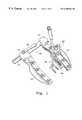
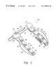
- FIG. 13is a perspective view illustrating an instrument mount assembly according to the principles of the present invention.
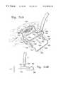
- FIG. 14is an exploded assembly illustration of the instrument mount assembly of FIG. 13 .
- FIGS. 15A and 15Bare perspective views illustrating the assembly of the mount cam to the mount base.
- FIGS. 16A and 16Bare top and front plan views, respectively, illustrating a preferred mount cam.
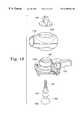
- FIG. 17is a front plan view illustrating a preferred mount hinge.
- FIG. 18is an exploded view illustrating the assembly of the mount body to the mount base.
- FIG. 19is an exploded view illustrating the assembly of the instrument clamp to the mount body.
- FIG. 20is a cross-sectional view taken through a horizontal plane of the instrument shaft grip of FIG. 19 .
- FIG. 21is a front plan view showing an assembled instrument mount operably positioned on a platform blade according to the principles of the present invention.
- FIGS. 22A and 22Bare front and top plan views, respectively, of an alternate instrument mount assembly according to the principles of the present invention.
- FIG. 23is a cross-sectional view taken along line 23 — 23 as shown in FIG. 21 .
- FIG. 24is an offset cross-sectional view taken along line 24 — 24 as shown in FIG. 22 illustrating the mount assembly of FIGS. 21 and 22 in the closed position.
- FIG. 25is an offset cross-sectional view illustrating the mount assembly of FIGS. 21 and 22 in the open position.
- FIG. 26is an exploded assembly view showing selected components of a preferred closing mechanism.
- FIG. 27is a perspective view illustrating a preferred instrument mount cam post.
- FIG. 28is a perspective view illustrating a preferred instrument mount release button.
- FIG. 29is a perspective view illustrating a preferred instrument mount follower post.
- FIG. 30is a perspective view of a preferred instrument mount shaft clamp.
- FIG. 31is a perspective view of a preferred instrument mount conical clutch.
- FIG. 32is a perspective view of a threaded collar associated with the instrument mount shaft clamp.
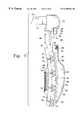
- FIGS. 33 and 34are exploded perspective and cross-sectional views respectively of a handle mechanism of a preferred tissue stabilizer.
- FIG. 35is an exploded perspective view of a contact member of the stabilizer shown in FIGS. 33 and 34.
- FIG. 36is a rear plan view of the contact member of FIGS. 33, 34 and 35 .
- FIG. 37is a cross-sectional view of the contact member of FIG. 36 taken along line 37 — 37 .
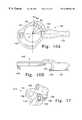
- FIG. 38is a perspective view illustrating a stabilizer base embodiment having an offset shaft connection.
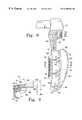
- FIG. 39is a perspective view illustrating an alternative offset stabilizer base in use over a target vessel.
- FIGS. 40A and 40Bare respectively front and side plan views of the offset stabilizer base embodiment of FIG. 39 .
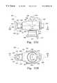
- FIG. 41is a perspective view of a tissue stabilizer having a moveable ball/post.
- FIG. 42is a perspective view illustrating another tissue stabilizer embodiment having a moveable ball/post.
- FIG. 43is a partial cross-section taken through the ball/post of FIG. 42 showing a spring biased ball/post.
- FIG. 44is a partial cross-section showing the ball/post of FIG. 43 utilizing a locking clip to secure the ball/post.
- FIG. 45is a perspective view of the locking clip of FIG. 44 .
- FIG. 46is a perspective view illustrating another moveable ball/post stabilizer embodiment.
- FIG. 47is a front perspective exploded view of a stabilizer base assembly having an adjustable ball/post position.
- FIG. 48is a rear perspective view of the stabilizer base of FIG. 47 .
- FIGS. 49A and 49Bare front and rear perspective views of the stabilizer base assembly of FIG. 47 .
- FIG. 50is a partial cross-sectional view through a portion of the rear guide slot of the stabilizer base of FIG. 47 .
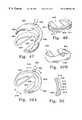
- FIG. 51Ais a perspective view of a stabilizer base embodiment having a single contact member and bail construction.
- FIG. 51Bis an end plan view of the stabilizer embodiment of FIG. 51 A.
- FIG. 52A and 52Bare perspective views illustrating another stabilizer base embodiment having a single contact member and bail construction.
- FIGS. 53 and 54are perspective views illustrating stabilizer base embodiments having a single contact member and a bail having a mechanical drive.
- FIG. 55is a perspective view of a preferred cardiac surgery system during operation according to the principles of the present invention.
- the present inventioninvolves surgical instruments stabilizing the heart and methods for their use.
- the present inventionmay also include a mount that allows various instruments to be easily positioned within the surgical working space, locked or secured into a desired position for the duration of a particular surgical procedure, and then easily and safely removed from the working space.
- the present inventionmay also involve a retractor system or assembly for accessing the heart.
- the instruments and methods of the present inventionmay have application in both conventional stopped-heart and beating heart procedures, they are preferably used to access and stabilize the beating heart during a minimally invasive coronary artery bypass graft (CABG) operation which has been specially developed to facilitate completion of an anastomosis, typically between a target artery and a bypass graft or source artery, without requiring cardiac arrest such as cardioplegia or fibrillation and without cardiopulmonary bypass (CPB).
- CABGcoronary artery bypass graft
- the instruments for accessing and stabilizing the beating heartcan be applied in a number of different surgical contexts involving various incisions and surgical approaches to the heart as are known in the art, the instruments and devices described herein are most advantageously employed in a CABG procedure wherein the heart is accessed through only one or two minimally invasive incisions in the chest.
- a common minimally invasive bypass procedure on the beating heartincludes an anastomosis which forms a connection between the left internal mammary artery (LIMA) as the source artery, and the left anterior descending artery (LAD) as the target artery.
- LIMAleft internal mammary artery
- LADleft anterior descending artery
- the surgeonmust dissect a portion of the LIMA by separating it from the internal chest cavity. Once dissection of the LIMA is achieved, the surgeon may attach the dissected LIMA to the target coronary artery, i.e., the LAD by way of creating an anastomosis.
- the present inventionmay involve a number of discreet components that facilitate access to the anastomosis site, allow various instruments or devices to be maneuvered and secured in place, and provide stabilization of the heart.
- the various stabilizer embodiments of the present inventionmay be used to stabilize the beating heart during at least the portion of the procedure during which the surgeon completes the anastomosis of the LIMA to the LAD.
- the mount of the present inventionmay be used to facilitate convenient manipulation of the stabilizer, and other instruments or devices, to their desired position and allows the devices to be secured in that desired position.
- the retractor of the present inventionmay be used to provide access to the anastomosis site of the target artery on the heart itself.
- each component of the present inventionmay be used separately with great benefit, the components are preferably used in unison to provide a surgical system which provides an unobstructed and organized surgical field, exceptional instrument maneuverability and access to the heart facilitating total revascularization of the heart if required, and effective vessel stabilization during the anastomosis procedure.
- the present inventionwill have application whether access to the heart is achieved by way of a full-stemotomy, mini-stemotomy, para-sternotomy, thoracotomy or other known approach, the exemplar embodiments described below will be generally described with reference to a coronary artery bypass procedure using a mid-sternal approach.
- FIG. 1an exemplar surgical system for performing a mid-sternal surgical procedure on the beating heart is illustrated in FIG. 1 and includes retractor assembly 10 , mount assembly 20 and stabilizer assembly 30 .
- Retractor assembly 10generally includes a pair of opposing blades adapted to engage opposite sides of a sternal incision, or other incision, and a drive mechanism constructed to force the blades, and thus the sternum apart. Using the drive mechanism, the sternum may be spread to the desired opening, thus providing the desired access and direct visualization of the thoracic cavity.
- the heartmay be positioned or oriented to best present the target vessels for anastomosis. This positioning may be established, for example, through the strategic placement and tensioning of sutures in the pericardial sac, by appropriately placing the patient in the Trendelenburg position, or by using a heart positioner in the form or a strap or pad or the like.
- At least one component of stabilizer assembly 30is brought into contact with the beating heart adjacent the target site of the anastomosis.
- the surgeonthen applies a stabilizing force to the beating heart via the stabilizer assembly 30 which may then be fixed in place, preferably to the retractor assembly 10 by way of mount assembly 20 .
- the stabilizing force supplied by the stabilizer assemblysubstantially eliminates movement of the heart in the area of the anastomosis so that the surgeon may accurately and efficiently perform the required anastomosis (or other surgical procedure).
- the stabilizing forceis released and the contacting component of stabilizer assembly 30 is removed from the anastomotic site.
- FIGS. 2-12A preferred retractor is described below with reference to FIGS. 2-12.
- a preferred stabilizer or instrument mount according to the principles of the present inventionis described below with reference to FIGS. 13-32.
- Preferred stabilizer embodiments according to the principles of the present inventionare described below with respect to FIGS. 33-44.
- a preferred surgical system and methods for performing a coronary artery bypass on a beating heart according to the principles of the present inventionis described below with respect to FIG. 45 .
- the preferred retractorgenerally involves a drive mechanism and a pair of opposing blades adapted for insertion into an incision and for engaging opposite sides of the incision.
- the drive mechanismfunctions in some manner to urge the opposing blades apart, thus forcing opposite sides of the incision open to allow surgical access through the incision.
- the incisionmay be any suitable incision which provides the desired access to the thoracic cavity, and more specifically a desired area of the heart.
- the retractor of the present inventionwill be described with respect to a mid-sternal incision, however skilled artisans will recognize that many aspects the invention are equally applicable to other surgical approaches to the heart, for example, by way of a thoracotomy, or other suitable access approach.
- the opposing bladesWhen the heart is accessed by way of an incision through all or a portion of the sternum, the opposing blades are adapted to be inserted into and engage opposite sides of a sternal incision such that the severed sternum may be forced apart by the action of the opposing blades to create a working space for operating on the heart.
- the drive mechanismis constructed to spread the opposing blades apart in a generally parallel fashion, however, the parting motion may also have a significant curvilinear or angular component as well.
- the bladesmay be permanently, integrally, or inseparably formed with a drive mechanism.
- a drive mechanismPreferably however, at least a portion of the blades are separable from the drive mechanism. That is, at least some of the features and functions associated with the retractor blades are allocated to a structural component which is separate, separable, or otherwise detachable from the drive mechanism.
- the separate component and the drive mechanismmay be manufactured independently and then subsequently assembled at the factory or, more preferably, at the point of use.
- a retractor construction having a separable componentallows the features and functions of the drive mechanism to remain separate from the remainder of the retractor assembly and vice versa.
- Thisallows a greatly simplified or depopulated drive mechanism and allows the separable component to have a much more sophisticated construction with increased features and functionality.
- the simplified drive mechanismwhich is typically required to be made from a hardened steel, is easier and more economical to manufacture and easier to maintain, clean and sterilize post surgically.
- the separate componentcan be economically made from materials or processes that allow for the intricate structural features which provide superior functionality.
- the drive mechanismis constructed to be resterilized and reused a relatively large number of times, and the feature-rich separate component is constructed to be disposable, i.e. discarded after a single surgical use.
- the depopulated drive mechanismwhich will be used over and over, can afford to be constructed to be quite robust with a view to materials and manufacturing processes that will support the rigors of such extended surgical service.
- the separable componentfree from the typical functional requirements of the drive mechanism and the service requirements of extended surgical re-use, may preferably be constructed from any number of engineering materials to produce an economical component having the desired features and which may be discarded after a single use if desired.
- retractor assembly 10comprises a drive 12 and first and second platform blades 14 and 16 detachably connected to drive 12 , as illustrated in FIG. 2 .
- first platform blade 14 and second platform blade 16each have one or more channels or engaging members 18 adapted to engage opposite sides of an access incision.
- Activation of drive 12forces apart first and second platform blades 14 and 16 thereby causing engaging members 18 to correspondingly force the incision open to provide access to the desired surgical site.
- engaging members 18are adapted to engage each side of the incised sternum to reliably hold and engage the sternum as the sternum is forced open to expose the thoracic cavity and ultimately the heart.
- engaging member 18is generally in the form of a channel or the like, preferably having a U-shape, curved shape, or other shape suitable for engaging the incised sternum.
- engaging member 18generally has a concave interior profile 17 for engaging and holding the sternum and a corresponding convex exterior profile 19 that is relatively smooth so as not to interfere with other surgical instruments, snag sutures or create other such difficulties.
- the engaging members 18are preferably constructed to have sufficient strength to withstand the loads required to spread the sternum yet maintain a suitably low profile to facilitate easy insertion into the access incision and to require as little space within the working incision as possible.
- engaging members 18may be desirable to provide engaging members 18 with features to reduce trauma to the incision site, increase the traction against the sides of the incision, or both.
- a thin pad or layer of non-slip or atraumatic materialmay be fixed, by way of an adhesive or other suitable fastening technique, to the interior profile 17 if desired to reduce slippage and trauma to the severed sternum or surrounding tissue.
- the desired featuresmay be integrally fabricated into engaging members 18 .
- traction featuressuch as raised bumps, ribs, indentations, or the like can be molded integral into engaging members 18 .
- drive 12is preferably constructed to force the platform blades apart in generally opposite directions. Any type of drive mechanism which provides the desired separating action of the blades may be suitable. A common, substantially straight-line parting motion may be provided by a ratchet or rack arrangement as is generally known in the art.
- FIG. 3illustrates a preferred drive 12 which involves a bar 15 , moveable housing 22 and handle assembly 24 which facilitates movement of moveable housing 22 relative to bar 15 . A first end of first blade 14 may be operably attached to moveable housing 22 and second blade 16 to bar 15 .
- bar 15is a substantially rigid bar having a stationary or fixed housing 21 assembled thereto and thus forming bar assembly 23 .
- Fixed housing 21may be fastened to one end of bar 15 using one or more mechanical fasteners, an interference fit, suitable adhesive or bonding compounds, welding, or any other suitable fastening technique.
- a first end of second blade 16is preferably operably attached to fixed housing 21 .
- fixed housing 21may be of any configuration which provides for the structural attachment of first and second platform blades 14 and 16 .
- Bar 15preferably includes a number of teeth 13 evenly spaced along at least a portion of its length. Teeth 13 may have substantially parallel side portions 11 and may have radiused tops 25 . The exterior edges of teeth 13 may be broken or radiused or have a chamfer 26 as shown.
- Handle assembly 24preferably includes a means for engaging teeth 13 so as to drive moveable housing 22 relative to bar 15 to any desired position under load where it remains so positioned against the load without need for any applied input or holding force.
- the means for engaging teeth 13could be any suitable gear, ratchet, cog or like mechanism. Bar 15 may also be adapted and used for receiving an instrument mount, such as those described in detail below.
- moveable housing 22is driven using one or more drive pins which may successively engage teeth 13 in a cogging manner.
- Handle assembly 24includes drive handle 29 connected to first and second cylindrical drive bearings 31 and 32 .
- Drive bearing 31preferably has a raised boss 34 extending from one end to which drive handle 29 may be pivotally connected by way of pin 33 .
- drive bearing 31has first drive pin 27 and second drive pin 28 extending therefrom and terminating at second drive bearing 32 .
- First and second drive bearings 31 and 32are spaced apart a distance 35 which is selected to be slightly greater than the thickness 38 of bar 15 such that a portion of bar 15 may be received between first and second drive bearings 31 and 32 .
- the outside diameters of drive bearings 31 and 32are selected so as to fit within guide holes provided in moveable housing 22 .
- the outside diameter of second drive bearing 32is sized to accurately rotate within guide hole 36 .
- Moveable housing 22has a bore 37 extending therethrough for receiving bar 15 .
- Bore 37generally has a shape corresponding to the dimensions of the cross-section of the portion of the bar 15 which is to pass through bore 36 .
- first and second platform blades 14 and 16may be removably assembled to moveable housing 22 and fixed housing 21 , respectively.
- Platform blades 14 and 16may be attached in any suitable fashion including, for example, threaded connections or other mating features on the platform blades and housings themselves, ordinary or specialized mechanical fasteners, and cam or latching mechanisms adapted to secure the platform blades to the housings.
- both moveable housing 22 and fixed housing 21are constructed with features that engage, secure and support first and second platform blades 14 and 16 in an operable position on drive 12 , thus providing an assembled retractor 10 which is ready for surgical use.
- second platform blade 16is shown before and after assembly onto fixed housing 21 .
- at least one of the platform blade 16 or the fixed housing 21has an extending protuberance, post or like feature which can be receivably engaged by the other of the platform blade or housing.
- fixed housing 21is preferably constructed to have a latch post 42 adapted to be received within latch post cavity 45 provided in platform blade 16 .
- Latch post 42may have a hole, notch, protuberance, or other feature formed therein which may be engaged in any convenient manner by the platform blade 16 so that platform blade 16 becomes releasably locked in place for use.
- latch post 16has a notch which defines latch surface 51 and stop surface 52 .
- Platform blade 16has a latch member 48 , best seen in FIGS. 11A-11C, having a latch body 50 constructed with surfaces 53 and 54 for engaging latch surface 51 and stop surface 52 respectively.
- platform blade 16has a latch body cavity 56 having an opening towards upper surface 57 of platform blade 16 for receiving latch body 50 of latch 48 .
- Latch 48is preferably constructed to engage and disengage latch post 42 by manual rotation of latch knob 49 .
- Latch body 50includes cylindrical portion 55 which provides for controlled rotation within latch body cavity 56 .
- Latch body 50may be biased towards the engaged position shown in FIG. 8 by way of any suitable spring element.
- latch post 42is provided with an angled tip 43 having a lead-in angle 44 which allows angled tip 43 to slide against second engaging surface 54 as latch post 42 begins to be received within latch post cavity 45 .
- angled tip 43causes latch 48 to rotate out of the way about cylindrical portion 55 .
- the angled tipis advanced beyond latch body 50 , and latch 48 (which is biased towards an engaged position) rotates into the engaged position with second engaging surface 54 biased against stop surface 52 .
- latch 48 and latch body 50snapped into the engaged position, any separating force encountered between platform blade 16 and fixed housing 21 is resisted by action of first engaging surface 53 against latch surface 51 .
- the reaction force at first engaging surface 53is advantageously borne by latch body 50 primarily in compression.
- latch 48can be made from standard engineering polymers, for example, such as polycarbonate.
- latch knob 49When it is desired to remove platform blade 16 from drive 12 , the operator simply turns latch knob 49 , causing latch body 50 to be placed in a disengaged position relative to latch post 42 . With latch 48 disengaged, latch post 42 of fixed housing 21 is free to be removed from latch post cavity 45 of platform blade 16 .
- a mirror image of the latch assembly described with reference to platform blade 16 and fixed housing 21is provided to releasably attach platform blade 14 to moveable housing 22 .
- platform blades 14 and 16are preferably made from a suitable engineering polymer (for example, a glass filled thermoplastic polyurethane resin), it may be desirable to provide a reinforcing member for each of platform blades 14 and 16 to ensure that platform blades 14 and 16 will not break or otherwise rendered inoperable as a result of the loads encountered during use.
- the reinforcing membersmay be a permanent or removable members within the platform blades themselves, the reinforcing members are preferably one or more substantially rigid members extending from each of the fixed housing 21 and the moveable housing 22 .
- fixed and moveable housings 21 and 22have a pin extending therefrom which may be received within a mating cavity within first and second platform blades 14 and 16 .
- the pinoperates to spread the load developed in the mechanism over a larger internal area within the platform blades 14 and 16 and reduces the effective beam length of unreinforced platform blade material subjected to the operating loads.
- the pinmay be straight pin 40 ′ illustrated in FIG. 3 .
- fixed and moveable housings 21 and 22have tapered pins 40 and platform blades 14 and 16 have mating tapered cavities 41 for receiving tapered pins 40 .
- the tapered constructiontends to allow the user to easily align pin 40 with cavity 41 and allows the pins 40 to fit relatively snugly within cavities 41 without significant binding during insertion that could otherwise occur between elongate pins and mating cavities which are designed to be very close fitting.
- the reinforcing pins 40are preferably constructed of a substantially rigid material, such as steel, and are preferably at least about 0.75 inches long, more preferably at least about 1.125 inches long, and most preferably between about 1.25 inches to about 2.25 inches long.
- reinforcing pins 40are made from AISI 420 stainless steel having a length of about 1.5 inches, an outside diameter near the housing of about 0.25 inches, and a 2 degree taper angle decreasing towards the free end of the reinforcing pins 40 .
- platform blade 16can be removed from drive 12 with a substantially straight-line relative motion as indicated by arrow 46 .
- This engagement actionnot only provides for simple and intuitive assembly in the operating room, but also represents a significant safety feature.
- the configuration described abovemay allow the drive to be separated from the in situ platform blades by releasing the latches and applying a sufficient amount of force in the direction indicated by arrow 46 . Once the drive has been removed, the detached platform blades may be easily removed from the patient.
- detachable platform blades 14 and 16may incorporate a wide variety of additional features which enhance the performance of the retractor system.
- one or both of platform blades 14 and 16may have mounting features to which various instruments used during the procedure can be secured.
- the engaging features 18 which engage the sternumare preferably part of a unitary platform blade structure which also includes mounting features to which a stabilizer and other instruments can be mounted. Since the mounting features and the sternal engaging features are part of the same component, and therefore there is no mechanical connection between the two, the stability of an attached instrument against the forces of a beating heart is greatly improved.
- each of first and second platform blades 14 and 16include mount features in the form of rails.
- the railsallow one or more instruments to be positioned at any desired location along the operable length of the rail.
- the railsare oriented in a direction generally perpendicular to the direction of separation, in this case perpendicular to bar 15 .
- the railsmay be a recessed feature within the body of platform blades 14 and 16 . More preferably, the mounting rails extend upwardly from the body of platform blades 14 and 16 .
- right platform blade 16has rail 60 extending over at least a portion of the length of platform blade 16 .
- Rail 60may have a top portion and a bottom portion having a narrowed region adjacent said top portion.
- Rail 60preferably has a T-shaped cross-section. The T-shaped configuration has a top portion 61 and a narrowed portion 62 , thus forming mounting tabs 63 and 64 which can be gripped by a number of appropriately constructed mounts.
- the railmay be straight, curved, or a combination of straight and curved portions.
- at least a portion of the T-shaped railis curved in a manner which more closely follows the profile of the access or incision site (as seen, for example, see FIG. 45 ).
- instruments extending perpendicular to a generally central axis 67 of rail 60will naturally point more towards a central area between the platform blades 14 and 16 , and thus may require less positional adjustment or manipulation from their normal, natural or beginning position.
- all or a portion of top portion 61 , and more specifically mounting tabs 63 and 64may be tilted or angled inwardly at an angle 65 as shown.
- Platform blade 16may be also be provided with a number of suture holders or stays which can be used to organize or capture various sutures used in the course of a particular surgery. Since certain sutures are placed near the beginning of a CABG procedure, such as pericardial sutures used to position the heart, the placement of the suture stays in a manner which does not interfere with subsequent procedures and instruments is an important aspect of the present invention.
- the suture staysare positioned such that placing and manipulating the sutures or the various instruments and instrument mounts employed during surgery can be accomplished without interfering with each other.
- the location of the suture staysposition the sutures below the level of the mounting tab 63 and 64 so that a mating instrument mount may traverse the entire operable length of rail 60 without interfering with the sutures.
- Rail 60may have one or more grooves, channels, slots or passageways for receiving a suture.
- a suture lockmay be provided in the rail or elsewhere on platform blade 16 so that the suture may be fixed in place.
- the suture locksmust be adapted to hold the suture material even while under a significant amount of tensile loading.
- rail 60has at least one open slot or passageway formed therein for receiving the free end portions of a surgically placed suture.
- the passagewayspreferably extend across rail 60 and have a depth which allows the suture to lay at an elevation sufficiently below mounting tabs 63 and 64 so as not to interfere with an instrument mount sliding along rail 60 .
- the passagewaysextend through at least a portion of narrowed portion 62 .
- the height 66 of narrowed portion 62may be selected not only to provide sufficient space for a desired instrument mount to attach, but also to ensure that mounting tabs 63 and 64 are sufficiently raised above the surrounding features of platform blade 16 so that an instrument mount may be positioned and repositioned along rail 60 without disturbing or disrupting the sutures within the various passageways.
- the passagewaysmay be a single channel for receiving both free ends of a surgically placed suture or each end may have a separate channel.
- rail 60has a number of bifurcated channels 70 at predetermined intervals along its length.
- bifurcated channel 70has a single entrance channel 71 which bifurcates into first and second exit channels 72 and 73 .
- Entrance channel 71 and either one of exit channel 72 or 73can be used in the same manner as a single channel, with both free ends 76 and 77 being routed together.
- both suture endsmay be received within entrance channel 71 and then separated, one end within exit channel 72 and one end within exit channel 73 .
- a means for clamping the suture against movement within the suture channelsmay be provided on any of entrance channel 71 or exit channels 72 or 73 .
- suture locksare provided on each exit channel 72 and 73 . This allows the surgeon to positively identify and unlock a desired suture end for further tension adjustments or other manipulation without unlocking or loosening the other end of the suture.
- placing each suture end 76 and 77 in separate exit channels 72 and 73 , each with a dedicated suture lockincreases the maximum amount of tension that can be applied to a given suture.
- Exit channels 72 and 73may have recesses 74 and 75 , respectively associated therewith for receiving a suture lock adapted to secure the suture material within the channels.
- Suture lock 80has a relatively rigid body 83 having a fixed or pivot end 81 which allows body 83 to pivot within the mating profile of recess 74 or 75 . Pivoting the body 83 about pivot end 81 selectively engages and disengages free end 84 against the wall 78 of exit channel 72 or 73 .
- suture lock 80may be made from a more flexible material which, by nature of the elastic properties of the material, tends to flex about its fixed end instead of rotate.
- fixed or pivot end 81is substantially cylindrical and recesses 74 and 75 have mating cylindrical surfaces.
- the suture lockis angled relative to the wall 78 so that it is self-locking in one direction. That is, the suture ends 76 or 77 (or both) operate on the free end 84 in such a way as to force it towards wall 78 , and thus against the suture material, in proportion to the tension, T encountered by suture ends 76 or 77 .
- the suture forcestend to pivot body 83 about pivot 81 such that free end 84 is rotated away from wall 84 allowing the suture to move relatively freely.
- angle 79 between body 83 and wall 78is nominally about 1 degree to about 30 degrees, more preferably about 5 degrees to about 15 degrees, most preferably about 10 degrees. Of course, angle 79 is greater as body 83 pivots to accept a suture placed within the suture channel.
- Suture lock 80may be biased towards the locked position, preferably using a small spring between the suture lock and the recess 75 .
- a piece of resilient closed cell foam 85is fixed to body 83 to provide the desired biasing effect.
- Free end 84may optionally have a number of teeth or ridges 82 to ensure acceptable traction against the suture material.
- Platform blades 14 and 16may also be provided with soft tissue retainers to help control and retain the incised tissue and fat in the immediate vicinity of the blades.
- platform blade 16includes integrally attached tissue retainer 85 .
- Tissue retainer 85is generally at a small distance 88 above the top of the engaging members 18 .
- Tissue retainer 85may be made from a flexible material, such as an elastomer, preferably a polyurethane elastomer having a durometer in the range of about 45 to about 75 Shore D, more preferably about 55 Shore D.
- tissue retainer 85is injection molded over the platform blade to form a permanent and inseparable assembly.
- Tissue retainer 85may have a raised outer lip 86 and optionally having a plurality of slots 87 formed therein to receive and organize any loose suture ends. Tissue retainer 85 ensures that the tissue surrounding the access incision does not interfere with the operation of rail 60 or the suture holders and also provides a convenient location for attaching surgical drapes of the like without interfering with the operation of the retractor assembly.
- first platform blade 14 and second platform blade 16are preferably substantially mirror images of each other.
- the retractor assembly just describedprovides a simplified drive mechanism for use in conjunction with multi-featured platform blades.
- a number of different platform bladesmay be provided for use with a single drive, for instance, tailored to different sized anatomy or the specifics of different surgical procedures.
- a number of platform blade configurationscan be provided to an operating room and, based upon pertinent prevailing clinical factors, the proper configuration can be selected, mounted to drive 12 , and used as described above to provide access to a desired location.
- new features and advancementscan be rapidly incorporated into the platform blades and immediately introduced for use with existing simplified drives already in place in the operating rooms.
- the platform bladesthemselves represent a surgical platform that allows instruments to be mounted and stabilized in virtually any position, even over already placed and secured sutures from the surgical site accessed by the retractor assembly. Described below are preferred instrument mounts for use in conjunction with rail 60 to secure a beating heart stabilizer or other instruments such as heart positioners, saline or medical air blowers, suction devices, surgical clamps, or vessel occluders.
- Mount assembly 20for mounting an instrument, such as stabilizer assembly 30 , to an instrument mounting rail such as described above with respect to rail 60 of platform blades 14 and 16 .
- Mount assembly 20includes mount base 115 having features to secure mount assembly 20 at a desired position on an appropriately configured mating rail or other suitable structure and includes a shaft locking mechanism for controlling and securing an instrument shaft in a desired position and orientation.
- instrument mount assembly 20provides the necessary degrees of freedom to allow the tissue stabilizer or other instrument to be easily maneuvered to whatever position may be required by a particular procedure.
- an additional aspect with respect to stabilizing the beating heartis to eliminate or minimize the flex or motion attributable to the various components and connections of instrument mount assembly 20 .
- instrument mount assembly 20is uniquely suited for use in stabilizing the beating heart because it allows sufficient degrees of freedom to easily manipulate the position of an instrument secured thereto, allows the degrees of freedom to be frozen or locked in place and, once locked in place, does not significantly flex or allow movement at any of the mechanical joints or connections.
- Instrument mount assembly 20provides a number of different controllable joints that, when in a released condition, allows motion in one or more predetermined directions or about one or more degrees of freedom.
- instrument mount assembly 20may be used to secure any mounting shaft configuration from straight or curved substantially rigid shafts to multi-link or segmented ball and socket type shafts which are relatively flexible until themselves locked in some manner at each joint along the shaft length, it is most advantageously constructed to provide the joints or connections required to position an instrument having a straight or curved rigid shaft.
- instrument mount assembly 20has three releasable joints or connections for controlling the location and position of the instrument mount assembly and instrument attached thereto.
- the mount basemay be positioned at a desired location along an appropriate rail and secured by rail grips 114 and 116 .
- the position and orientation of the instrumentis then determined by ball joint (or ball and socket joint) 112 between mount base 125 and mount body 110 , a rotational joint 157 between mount body 110 and shaft hub assembly 160 , and a shaft clamping mechanism within shaft hub assembly 160 which may allow translation, rotation, or both of shaft 3 relative to shaft hub assembly 160 .
- Ball joint 112is preferably of the ball and socket type having 3 rotational degrees of freedom.
- Rotational joint 157allows rotation of shaft hub assembly 160 about axis 121 as indicated by arrow 113 .
- the shaft clamping mechanismallows translation of instrument shaft 3 as indicated by arrows 111 as well as rotation about the shaft itself as indicated by arrow 117 .
- a further ball-joint type connection 201may be employed between shaft 3 and the particular end-effector of the instrument.
- Instrument mount assembly 20having the particular joints and connections identified above, allows all the required areas of the heart to be conveniently and intuitively accessed by a stabilizer connected to one end of a substantially rigid shaft.
- instrument mount assembly 20could be provided with more or less degrees of freedom for maneuvering a particular instrument.
- rotational joint 157could be replaced with a ball joint and to eliminate degrees of freedom shaft 3 could be keyed within shaft hub assembly 160 or ball joint 112 could be replaced with a rotation only joint.
- excessive degrees of freedommay tend to make instrument adjustment increasingly difficult and cumbersome to control while too few degrees of freedom may not allow the instrument to be easily placed in the desired position or orientation.
- the various joints and connectionsare locked into a desired position by way of a series of knobs.
- the degrees freedom provided by ball joint 112is locked by activation of top mount knob 120 .
- Both rotational joint 157 and the shaft clamping mechanism of shaft hub assembly 160is locked in place by the activation of side mount knob 118 .
- Base 125is locked in position on the rail by activation of mount lever 122 .
- Ball joint 201may be locked in position by activation of knob 504 .
- This particular sequence of knobs used to lock down the degrees of freedom associated with instrument mount assembly 20tends to allow the user greater precision in positioning the instrument because degrees of freedom unnecessary to a particular desired maneuver of the instrument can be locked down.
- mount body 110is placed at a desired angle or orientation and then fixed in place by locking ball joint 112 , leaving final adjustment to take place using rotational joint 157 and the shaft movement allowed by the shaft clamping mechanism of shaft hub assembly 160 .
- FIGS. 14-20show in greater detail the various mechanisms which lock and release the joints or connections associated with instrument mount assembly 20 .
- FIG. 14shows an exploded assembly illustration of instrument mount assembly 20 .
- Instrument mount assembly 20and more specifically mount base 125 to which all the other components are ultimately secured, is preferably constructed to engage and lock in position on a rail or other suitable feature.
- instrument mount assembly 20has a fixed rail grip 114 adapted to engage mounting tab 64 of rail 60 and a moveable rail grip 116 adapted to engage mounting tab 63 or rail 60 .
- Rail grips 114 and 116may generally have hook-like features for gripping mounting tabs 63 and 64 .
- Rail grip 114is part of mount base 125 and moveable rail grip 116 is part of articulating hinge member 115 , which is pivotally attached to mount base 125 by way of hinge pins 123 and 124 , or other suitable fastener. Articulation of hinge member 115 and rail grip 116 in clamping manner towards rail grip 114 on mount base 125 effectively clamps mount base 125 onto rail 60 at mounting tabs 63 and 64 .
- Hinge member 115may be articulated using any suitable mechanism capable of pivoting hinge member 115 to a closed position and holding it there.
- hinge member 115includes follower surface 155 which may be acted upon by any suitable cam device to drive hinge member 115 about hinge pins 123 and 124 , thus urging rail grip 116 towards rail grip 114 .
- hinge member 115is articulated by action of cam 145 having cam surface 152 which acts upon follower surface 155 .
- Cam 145has a center, C about which cam 145 rotates.
- cam 145has bore 127 , having its central axis coincident with center, C.
- Mount base 125may have a cam guide 153 around which bore 127 rides for smooth rotation of cam 45 about center, C.
- Cam surface 152has a varying radius, illustrated by exemplar radial lines R 1 , R 2 , R 3 , R 4 , and R 5 .
- cam surface 152is rotated past follower surface 155 , from example from R1 to R2, it pushes the follower surface a greater distance away from center, C, thus causing hinge member 115 to pivot about hinge pins 123 and 124 , thus causing rail grip 116 to move closer to rail grip 114 .
- the varying radius of cam surface 152may be configured to place hinge member 115 , and thus rail grip 116 in a variety of positions.
- a first portion of cam surface 152may be configured such that follower surface 155 biased against cam surface 152 is placed in an position characterized in that rail grip 116 is sufficiently spaced apart relative to rail grip 114 to allow assembly onto a rail or other structure.
- a second portion of cam surface 152has an increasing radius such that rotation of cam 145 moves rail grip 116 towards rail grip 114 to an intermediate position. In the intermediate position, rail grip 116 has been moved close enough to rail grip 114 so that it becomes captured on a rail but remains loose enough to slide along the rail.
- a third portion of cam surface 152has an increasing radius such that the rotation of cam 145 moves rail grip 116 further towards rail grip 114 to a completely locked position wherein relative motion between rail grips 114 , 116 and the rail is essentially no longer possible.
- Cam 145is generally provided with a handle or lever 122 to allow the user to easily turn cam 145 relative to mount base 125 .
- Cam 145may be captured onto mount base 125 by operation of retaining hook 150 on cam 145 which rides within exterior groove 151 on mount base 125 on one side, and projection 154 which is engaged below undercut 156 generally opposite to retaining hook 150 .
- Projection 154also serves to work against undercut 156 to return hinge member 115 to the open position as cam 145 is rotated in the opposite (open) direction.
- Hinge member 115preferably has first and second end stops 158 and 159 between which the motion of projection 154 (and thus the rotation of cam 145 ) is limited.
- Cam 145may also have a protective extended portion or cover 163 which shields the area of groove 151 when assembled over mount base 125 .
- cam 145 and hinge member 115The assembly of cam 145 and hinge member 115 to mount base 125 is illustrated in FIGS. 15A and 15B.
- Cam 145is placed in position relative to hinge member 115 with projection 154 in place below undercut 156 .
- cam 145 and hinge member 115are brought over mount base 125 until bore 127 is properly seated over cam guide 153 and retaining hook 150 is positioned within groove 151 .
- Pins 123 and 124are then pressed in place through holes provided in both mount base 125 and hinge member 115 .
- Ball joint 112is generally created between ball 129 provided at the top of mount base 125 and a socket or mating cavity within mount body 110 adapted to receive at least a portion of ball 129 .
- ball 129includes a generally spherical portion, although other curved shapes providing the desired degrees of freedom may also be suitable.
- Base post 130extends vertically upward through bore 126 of mount base 125 and vertical passageway 128 of mount body 110 until enlarged end portion 130 become biased against mount base 125 .
- Top mount knob 120may then be threaded onto threaded shaft 132 whereby mount base 125 and mount body 110 , with ball 129 received within mount base 125 , becomes captured between top mount knob 120 and enlarged end portion 130 . Continued tightening of top mount knob 120 over threaded shaft 132 forces ball 129 harder against mount body 110 until the friction between mating surfaces on ball 129 and mount body 110 become so great as to effectively resist any relative movement, thus locking ball joint 112 .
- Rotational joint 157is in the form of a conical clutch formed between frustoconical surface 138 of clutch member 135 and mating frustoconical surface 139 in mount body 110 .
- Shaft hub assembly 160is generally formed as upper and lower shaft locks 136 and 137 are advanced over shaft grip 140 and against instrument shaft 3 which is positioned between shaft locks 136 and 137 and outer shaft guide 144 . As clutch member 135 is received over the outside diameter of grip housing 141 of shaft grip 140 tang 164 becomes engaged between upper shaft lock 136 and lower shaft lock 137 thereby preventing relative rotation between clutch member 135 and shaft grip 140 .
- Side mount knob 118 having threaded shaft 119extends through mount body 110 (and consequently through transverse bore 131 in central portion 167 of base post 130 ), clutch member 135 and into interior threads 142 within grip housing 141 of shaft grip 140 . Tightening of side mount knob 118 clamps the assembly together.
- translation and rotation of instrument shaft 3is prevented as shaft grip 140 and clutch member 135 are forced together to clamp or trap instrument shaft 3 between shaft locks 136 and 137 and outer shaft guide 144 .
- relative rotation between frustoconical surface 138 of clutch member 135 and mating frustoconical surface 139 in mount body 110is prevented as clutch member 135 is forced against mount body 110 .
- One or both of frustoconical surface 138 and mating frustoconical surface 139may include a number of teeth, ridges, or other features to prevent rotation when clutch member 135 is forced against mount body 110 .
- shaft biasing member 147is provided within shaft grip 140 to maintains a biasing load against shaft 3 .
- Shaft biasing member 147has a first portion 148 which slides within counterbore 143 in shaft grip 140 .
- Shaft biasing member 147may optionally have a second portion 149 having external dimensions sized to be received within the inside diameter of compression spring 133 .
- Compression spring 133urges end 134 of shaft biasing member 147 against shaft 3 to force shaft 3 against clamping surfaces 146 . The amount of force is selected to allow instrument shaft 3 to be easily positioned by hand but would generally not allow instrument shaft 3 to slide relative to shaft grip 140 under only its own weight.
- a preferred instrument mount assembly 20is shown fixed to a preferred platform blade 16 having rail 60 .
- rail 60has mounting tabs 63 and 64 over which rail grips 114 and 116 may be secured.
- Instrument mount assembly 20can be positioned, maneuvered, and removed virtually anywhere along rail 60 without disturbing suture 166 locked in place by free end 84 of suture lock 80 below the operating features of instrument mount assembly 20 within any one of the suture channels provided in platform blade 16 .
- rail 60is placed in close proximity to engaging member 18 and thus close to the surgical opening into the patient providing a more direct access to the heart by an instrument mounted to instrument mount assembly 20 . Since the rail 60 moves in unison with platform blade 16 , this relationship between rail 60 and engaging member 18 is maintained no matter how much or how little platform blades 14 and 16 have been spread to create the desired surgical opening.
- FIGS. 22A-32illustrate a preferred embodiment of an alternative instrument mount assembly 220 .
- the degrees of freedom available for maneuvering instrument mount 220is substantially the same as that of instrument mount assembly 20 .
- Instrument mount assembly 220preferably has ball joint 112 between mount base 221 and mount body 222 , a rotational joint 157 between mount body 222 , and a shaft hub assembly 227 which allows rotation and translation of an instrument shaft held between shaft grip 226 and clutch member 226 of shaft hub assembly 227 .
- Instrument mount assembly 220has a different mechanism for controlling or locking the various joints and connections and may also provide a means for releasing and removing the shaft from the bulk of the remainder of instrument mount assembly 220 .
- ball joint 112is a ball and socket configuration created between generally spherical ball 224 provided at the top of mount base 221 and a mating cavity within mount body 222 adapted to receive and slide against at least a portion of ball 224 .
- Rotational joint 157may be in the form of a conical clutch formed between frustoconical surface 243 of clutch member 225 and mating frustoconical surface 244 in mount body 222 .
- An instrument shaftmay be clamped in place within shaft hub assembly 227 by forcing together shaft grip 226 and clutch member 225 thus closing clamp surface 239 of outer shaft guide 233 towards V-shaped channels 273 on shaft locks 231 and 232 .
- instrument mount assembly 220preferably uses a mechanism which releases each of ball joint 112 , rotational joint 157 , and the shaft clamping mechanism of shaft hub assembly 227 by activation of a single knob, lever, or other suitable manual interface. Generally speaking, this is accomplished by utilizing the clamping motion required to lock one or more of the joints or connections along a first axis to also lock the remainder of the joints or connections along remaining axes.
- ball 224 of mount base 221is locked in place relative to housing 222 by operation of base post 230 .
- Base post 230is assembled through mount base 221 and mount body 222 from the bottom until bottom flange 259 (see FIG. 27) is resisted against mount base 221 .
- At the top of base post 230is upper link portion 256 having pivot hole 257 .
- Cam 235is attached through pivot hole 257 at off-center link pivot 238 using a pin or other suitable fastener and is supported by contact surface 236 associated with mount body 222 .
- Contact surface 236may be an integral feature of mount body 222 or may be in a separate mount body cover 254 which may be selected to have superior wear characteristics.
- link pivot 238With cam 235 in a closed position, as shown in FIG. 24, link pivot 238 is drawn to its maximum distance 251 (or slightly less than the maximum if the cam is constructed to rotate over center) from contact surface 236 thus increasing the clamping force between mount body 222 and ball 224 as the assembly is clamped between cam 235 on the top and bottom flange 259 on the bottom. With cam 235 in the closed position, ball joint 112 is effectively locked.
- link pivot 238By rotating cam 235 , by way of handle 237 , to an open position as illustrated in FIG. 25, link pivot 238 is withdrawn to a position closer to contact surface 236 at a distance 252 , thus reducing or relaxing the clamping forces between mount body 222 and ball 224 of mount base 221 . With cam 235 in the open position, the friction at ball 224 is reduced to a level that allows the user to easily manipulate mount body 222 relative to mount base 221 .
- Mount base 221may have an insert 253 secured in the bottom thereof against which bottom flange 259 is caused to seat as upper link portion 256 is drawn upwards by operation of cam 235 .
- insert 253includes recess 255 for receiving compression spring 248 captured about base post 230 .
- Compression spring 248operates between insert 253 , and thus mount base 221 , and bottom flange 259 to bias base post 230 towards the unlocked position.
- instrument mount assembly 220preferably utilizes tie pin 240 which is driven in the direction of arrow 245 causing shaft grip 226 and clutch member 225 to be forced together to clamp an instrument shaft placed therein and also causing frustoconical surface 243 of clutch member 225 to forced against frustoconical surface 244 in mount body 222 .
- Tie pin 240preferably has a generally cylindrical back portion 261 and a front portion which is connected in some manner to shaft grip 226 .
- the front portionincludes forward extending first and second flexible prongs 262 and 263 .
- Cylindrical back portion 261is slidably received within blind hole 272 of release button 242 and is preferably biased in the unlocked direction indicated by arrow 270 by compression spring 247 positioned within blind hole 272 behind tie pin 240 .
- Tie pin 240is preferably driven in the direction of arrow 245 by the movement of base post 230 which is assembled in the space between first and second prongs 262 and 263 of tie pin 240 .
- base post 230has an angled cam or ramp 258 that engages back wall 269 at the base of first and second prongs 262 and 263 .
- ramp 258progressively forces back wall 269 , and thus tie pin 240 , in the direction of indicated by arrow 245 .
- Tie pin 240connected at its front end to shaft grip 226 , locks an instrument shaft in place and locks rotational joint 157 in the same manner as did threaded shaft 119 of instrument mount assembly 20 .
- tie pin 240urges shaft grip 226 towards clutch member 225 and mount body 222 .
- the movement of shaft grip 226having tang 236 engaged between upper and lower shaft locks 231 and 232 of clutch member 225 , closes together in a clamping fashion surfaces 239 on shaft grip 226 and V-shaped channels 273 on clutch member 225 .
- shaft grip 226pushes against clutch member 225 to force frustoconical surface 243 against mating frustoconical surface 244 with sufficient force to frictionally lock the surfaces together, thus preventing relative motion therebetween.
- cam 235has been described as generally moving between an open position, in which the various joints and connections of instrument mount assembly 220 are free to be easily manipulated about their respective degrees of freedom, and a closed position in which the joints and connections resist any relative movement and are thus effectively locked in position.
- the outer cam profile of cam 235 operating against contact surface 236may be given a profile that has one or more intermediate positions such that link pivot 238 is placed at an intermediate distance from contact surface 236 .
- the joints and connectionsmay be in a stiffened or partially locked state which allows some positional and orientational manipulation with somewhat higher operator forces that the completely released condition.
- the action of base post 230may be such that ball joint 112 becomes fully locked before tie pin 240 has completely locked the remaining degrees of freedom.
- cam 235may have a completely released position where manipulation about all degrees of freedom is easily accomplished, an intermediate position in which only ball joint 112 is fully locked and the remaining degrees of freedom are unlocked or may be partially locked, and final closed position in which all degrees of freedom are locked.
- Instrument mount assembly 220may optionally be provided with a release mechanism allowing shaft grip 226 , and thus the instrument shaft slidably assembled therein, to be released from instrument mount assembly 220 preferably by activation of release button 242 . This allows instruments associated with instrument mount assembly 220 to be quickly and conveniently removed and replaced or exchanged.
- first and second prongs 262 and 263 of tie pin 240have first and second projections 267 and 268 which releasably attach tie pin 240 to shaft grip 226 .
- Grip housing 274 of shaft grip 226is covered with a sleeve having a deep counterbore 278 and small through hole 279 .
- the depth of counterbore 278is longer than the exterior of grip housing 274 so as to form internal space 290 (see FIG. 25) when assembled.
- First and second prongs 262 and 263can be flexed to position projections 267 and 268 relatively close together for insertion through hole 279 where projections 267 and 268 can then expand apart locking projections 267 and 268 behind surface 280 .
- projections 267 and 268have lead-ins 291 and 292 which urged projections 267 and 268 together as they are advanced through hole 279 so that shaft grip 226 can simply be aligned with lead-ins 292 and 292 and then snapped into place without any further action.
- Alignment of hole 279is generally quite simply accomplished as the cylindrical exterior surface 277 of sleeve 260 is slidably received in a substantially coaxial arrangement within center bore 219 of clutch member 225 .
- Clutch member 225may optionally have first and second flexures 281 and 282 having first and second retaining features 283 and 284 so that it may be snapped in place and thereafter retained within mount body 222 .
- shaft grip 226may be released from tie pin 240 .
- To separate tie pin 240it is necessary to flex first and second prongs 262 and 263 together so that projections 267 and 268 will again be positioned to fit through hole 280 .
- Thismay be accomplished by providing a raised portion 264 having a ramp 266 on tie pin 240 .
- a sliding membermay be advanced up tie pin 240 and over ramp 266 and raised portion 264 thus flexing prongs 262 and 263 inwards.
- the sliding memberis a tip portion 289 of release button 242 .
- Tie pin 240is slidably received within blind hole 272 of release button 242 .
- blind hole 272The internal diameter of blind hole 272 is small enough so that when it is advanced over ramp 266 and/or raised portion 264 , prongs 262 and 263 are flexed inwards.
- the entrance to blind hole 272has an internal chamfer 288 so that ramp 266 is smoothly engaged as release button 242 is advanced.
- Release button 242preferably has a generally cylindrical body 285 which is slidably received within mating bore 294 (see FIG. 25) of mount body 222 . Release button 242 is retained in place, and its sliding travel limited, by release button flange 241 on one end and spring clip or e-clip 293 assembled within e-clip groove 286 on the other end.
- Spring material 246such as a wave spring washer or foam material, may be disposed between release button flange 241 and mount body 222 to bias release button 242 outwards.
- Transverse to blind hole 272 tip portion 289also has a clearance slot 287 through which base post 230 passes.
- FIGS. 22A-25have illustrated instrument mount assembly 220 without hinge member 115 and cam 145 attached.
- hinge member 115 having rail grip 116is preferably pivotally mounted, with cam 145 in place, by way of pins or the like at hinge mount 228 as described above with reference to instrument mount assembly 20 .
- cam 145may be rotated about cam guide 223 using base lever 122 to secure the instrument mount to a rail or other suitable structure.
- the retractor and instrument mounts described abovecan be used to mount and stabilize a great number of instruments for use during surgery.
- the retractor and instrument mountsare used to mount a mechanical stabilizer for stabilizing at least a portion of the beating heart during CABG surgery or the like. Described below are a number of mechanical stabilizer embodiments that are particularly beneficial for stabilizing the beating heart, especially when used in conjunction with the retractors and instrument mounts described above.
- a means for stabilizing the beating heartis introduced through the opening created and at least one component of the stabilizing device of the present invention is brought into contact with the beating heart.
- the surgeonthen applies a stabilizing force to the beating heart via the stabilizing means which may then be fixed in place by attachment to a fixed support.
- the retractor platformmay also provide the stable support structure to which the stabilizing means is affixed.
- the structure of the portion of the stabilizing means which contacts the heartmay include one or more contact members which exert a stabilizing force on the heart proximate to the site of the anastomosis.
- a pair of contact membersmay be plates or rectangular members which are placed on either side of the target coronary artery at the site of the anastomosis and which may have friction means or tissue spreading or compressing apparatus associated therewith.
- the contact membersmay also be provided by a platform which may be substantially planar or which may be contoured to fit conformingly on the surface of the heart.
- the stabilizing meansmay also include a shaft means having several alternative embodiments to facilitate adjusting the position and orientation of the instrument.
- the shaft meansmay have an adjustable length and the axis of the shaft means may have at least one ball joint disposed within its length such that the orientation of the shaft means relative to another structure such as the contact members or stable support may be continuously varied.
- each of the individual embodiments described and illustrated hereinhas discrete components and features which may be readily separated from or combined with the features of any of the other several embodiments.
- a preferred stabilizer assembly for stabilizing the beating heartis comprised of a foot or base portion 553 attached to a rigid or semi-rigid shaft means or connecting shaft 3 .
- Base portion 553typically has one or more contact members 1 adapted to contact the heart adjacent the site desired to be stabilized.
- the contact members 1may be substantially planar, may be slightly curved to conform to the shape of the heart, or may be a non-conforming curve to establish contact between only a portion of the contact member 1 and the beating heart.
- the shape of the contact membersmay be varied depending on the clinical assessment by the surgeon, the design of the other features of the stabilizing means, or the design of other instruments used to complete the anastomosis.
- the contact members 1may have apertures, openings or attachments to facilitate connection with sutures or other devices to achieve the requisite stabilization, occlusion of the target vessel, or exposure of the target vessel.
- suitable base portions and contact memberscan be found, for example, in co-pending U.S. patent application Ser. No. 08/931,158 filed on Sep. 16, 1997, entitled “SURGICAL INSTRUMENTS AND PROCEDURES FOR STABILIZING THE BEATING HEART DURING CORONARY ARTERY BYPASS GRAFT SURGERY”, the entirety of which is herein incorporated by reference.
- the proximal end of connecting shaft 3has handle mechanism 468 assembled thereto which, among other things, provided the user with a means for locking an end effector operably attached to the distal end of connecting shaft 3 .
- the mechanism 468is rotatably secured to the proximal end of the shaft means 3 and is formed at a selected angle to the shaft means to permit a surgeon to swivel the mechanism to a preferred position where the knob 504 is more readily accessible to allow quickly locking the shaft means 3 in the orientation selected.
- the angled axis of the knob 504 relative to the shaft means 3reduces the tendency of the shaft means 3 to rotate about its axis when a surgeon applies torque to the knob 504 to lock the associated locking mechanism.
- the knob 504is secured to a screw 539 by suitable means such as press fitting, bonding, etc.
- Right and left handle covers 540 , 541comprise the handle 503 and provide the support for the handle mechanism. When assembled, the covers define generally a cylinder formed with a selected curvature.
- a secondary inner molding, generally indicated at 542includes various integrally formed annular walls and shoulders for supporting and containing the knob 504 and screw 539 , as well as a cooperating nut 543 , and arcuate wedge 544 , a shaft retaining ring 545 , the proximal end of the shaft means 3 , and a proximal end of the translatable pushrod 505 .
- the proximal end of the shaft means 3includes an annular retaining ring slot 546 which secures the proximal end of the shaft means 3 within suitable annular walls in the corresponding end of the handle covers 540 , 541 when the retaining ring 545 , confined by shoulders in the inner molding 542 , is snapped into the slot 546 and the covers are assembled.
- the nut 543is confined by shoulders in the inner molding 542
- the arcuate wedge 544is slidably confined by correspondingly arcuate walls 547 also formed in the inner molding.
- the shaft means 3 and thus the pushrod 505are formed with a slight arcuate configuration, which permits additional degrees of freedom and movement and orientation of the distal end of the shaft means 3 and thus of the heart contact member 1 .
- Rotation of the shaft means 3 about the axis of confinement within the shaft grip 495 or 495 amoves the distal end of the shaft means 3 through a circular path while changing the angles through which the contact member 1 can be oriented. This allows a surgeon to conveniently achieve a wider range of positions and orientations of the contact member relative to the patient's heart, while keeping the proximal end of the shaft means 3 and handle mechanism 468 out of the way as much as possible.
- FIGS. 35-37illustrate an associated mechanism for maneuverably supporting the various embodiments of the contact member 1 and for cooperatively assisting in the quick locking of the contact member by a partial rotation of the knob 504 once the member is positioned.
- the distal end of the shaft means 3is provided with exterior threads matching interior threads in a ball/socket 548 .
- the distal end of ball/socket 548is provided with slots 549 , whereby the remaining material comprises short extended tips 550 which, when bent in or inwardly formed, form a socket.
- a ball/post 551includes a ball at one end and a post at the other.
- the ball/post 551When the mechanism is assembled, the ball/post 551 is inserted into place within the ball/socket 548 with the ball in the socket and the post protruding from the ball socket.
- a mechanism for providing a preloaded sourcesuch as a compression spring 552 , is coupled to the ball/socket 548 abutting the ball.
- the spring 552is urged by the distal end of the shaft means 3 to exert a preloaded or constant minimum force against the ball of the ball/post 551 .
- the post of the ball/post 551is solidly fixed as by pressing fitting, welding, etc., to the contact member 1 .
- the distal end of the pushrod 505passes through the spring 552 to abut the ball of the ball/post 551 .
- the distal end of the pushrod 505exerts a slight pressure against the ball, however the spring 552 maintains a preloaded force against the ball sufficient to maintain the contact member 1 at any orientation set by a surgeon.
- the pushrod 505is forced against the ball to prevent any further movement of the contact member 1 .
- the contact member 1can be tilted to assume many orientations since the narrow center of the post can tilt into any of the four slots in the ball/socket 548 .
- simultaneous rotation of the curved shaft means 3provides a surgeon with an even greater variety of orientations of the contact member relative to a patient's heart.
- the contact member 1includes a preferred configuration which improves the size of the area of the heart which is visible to a surgeon while still providing the required suppression of heart movement necessary to enable the efficient construction of the anastomosis. More particularly, the pair of spaced-apart contact members 1 extend from a common base portion 553 , which uniquely first extends back away from the tips of the contact members at the point of attachment to the post, as shown at reference number 554 . The spaced contact members 1 then curve downward away form the common base portion 553 and back past the post and away from the shaft means 3 . As may be seen in the FIGS. 35-37, the contact member 1 of this embodiment uniquely is attached to the post on the same surface as the surface that bears against the surface of the beating heart. Since the members 1 separate at the base portion 553 at a point 555 behind the distal end of the shaft means 3 , a surgeon has an unobstructed and thus optimum view of the heart even below the distal end of the shaft means 3 .
- the contact memberspreferably include friction means 556 selectively secured to the bottom surfaces thereof to more securely engage a beating heart.
- the tips of the contact membersare bent upward in the form of “ski tips” to lessen their impact when the contact members are firmly pressed against a beating heart to suppress the anastomotic site.
- screw means 539 / 504 / 543is illustrated herein as a locking mechanism of the handle mechanism 468 , it is to be understood that other mechanisms may be employed.
- a cam/lever mechanismmay be attached to a rod which in turn imparts a pivoting movement or translation to a suitable bellcrank or pivotable member, which in turn imparts translation to pushrod 505 of the shaft means 3 .
- locking mechanismsother than those specifically described herein may be used.
- the basic configuration as just described with reference to base portion 553provides the maneuverability necessary to access and stabilized any desired vessel on the surface of the beating heart.
- the exact manner and position in which the stabilizer may be placed relative to the vessel and the surgical techniques preferred by an individual surgeonmay vary significantly. Accordingly, there is some potential that certain combinations of stabilizer positioning may interfere somewhat with the preferred surgical technique of a particular surgeon.
- the embodiments illustrated below with respect to FIGS. 38-40Balleviate any such problems.
- connectionconnects connecting shaft 3 to the base portion of the stabilizer at a position which is generally offset from the center or off-center.
- Base portion 710is again typically formed of a unitary piece of sheet material and has a curved back portion in which connecting shaft 3 is attached to an extension of S the same surface which carries the contacting members, except that the connecting point 718 , to which ball/post 551 is attached is positioned away from the center and therefore away from the space between contact members 712 where the anastomosis would be performed.
- This configurationtends to ensure that connecting shaft 3 will not interfere with the surgical access to the center area of the base portion.
- the connectioncan be offset from the central region in either direction.
- base portion 710illustrates a number of features for improving the traction and vessel presentation during a CABG procedure on a beating heart.
- Contact members 712 of base member 710have portions 713 having an increased width and which are preferably substantially flat or slightly curved to conform to the heart. This configuration provides a larger area for coined regions 715 , which represent indentations on the bottom surface for receiving a traction material, thus providing greater traction against the surface of the heart.
- base portion 710provides a smaller open space between contact members 712 .
- the spacing 716 between contact members 712is less than about 0.350 inches, more preferably less than about 0.300 inches, and most preferably about 0.25 inches. This minimized spacing provides stabilization closer to the vessel and, in some instances, the compressive forces applied through contact members 712 actually tend to present the vessel upwards between contact members 712 in a more favorably pronounced manner.
- the tip portions 714 of contact members 712are angled upwards from the surface of the heart to minimize any possible trauma to the heart during use.
- the base portions ( 550 or 710 )can be manipulated or oriented relative to the end of the connecting shaft 3 by virtue of the ball and socket joint between base portion 553 and connecting shaft 3 .
- the amount of angular manipulation or travel availableis somewhat limited as ball/post 551 eventually bottoms out or stops against either the bottom of slots 549 or extended tips 550 .
- the contact membershave a limited range of movement relative to connecting shaft 3 based upon the nominal mounting relationship between the contact members and the ball/post. Accordingly, for some procedures, it may be desirable to have a different nominal relationship between the contact members and the ball/post to shaft connection.
- base member 720illustrates an alternative orientation of ball/post 551 .
- base member 720has a back portion 721 which allows ball/socket 551 to be mounted generally parallel to contact members 722 .
- Ball/post 551preferably extend towards contact members 722 as shown, but may also extend the opposite direction away from the contact members.
- the connecting point 723is preferably offset a distance 724 from the central area between the contact members 722 .
- the connecting point 723is also off set a greater distance 726 from the contacting place of contact members 722 . In nominal position of base portion 722 relative to ball/post 551 , this configuration tends to keep the connecting shaft 3 clear from the central portion between contact members 722 .
- contact members 722can be maneuvered through a range of motion different from base member 553 due to the initial orientation of ball/post 551 .
- ball/post 562has threaded end 561 which may be threaded into any desired threaded receiving hole 563 provided in stabilizer base 560 .
- Ball post 564is preferably provided with one or more flats 564 on the exterior thereof to facilitate tightening or loosening of the threaded connection.
- stabilizer base 560has threaded receiving holes 563 to provide center, offset right, and offset left connecting positions.
- slot 571preferably has two or more positions where the ball/post can be positively locked.
- slot 571preferably has two or more key-hole openings 573 .
- Key openings 573are sized to receive first post portion 577 having an outside diameter which closely matches the inside dimension of key opening 573 .
- First post portion 577 of ball/post 572is released from key hole 573 by pulling ball post in the direction indicated by arrow 579 until second post portion 578 is positioned within keyhole 573 .
- Second post portion 578is sized to have an outside diameter small enough to fit and traverse through slot 571 .
- Ball/post 572may then be traversed along the path defined by slot 571 until the next desired key hole is reached, which may then be engaged by first post portion 577 to secure ball/post 572 in position on stabilizer base 570 .
- First post portion 577may be kept in engagement with keyholes 573 by any convenient manner.
- ball/post 572may be spring biased in the locked position between upper flange 574 and lower flange 575 , preferably using spring washers 576 as shown.
- Ball/post 572may also be locked into operating position within keyholes 573 by using a retaining or locking clip, such as locking clip 580 illustrated with reference to FIGS. 44 and 45.
- Locking clip 580has slot 584 adapted to slide over second post portion 578 .
- Locking clip 580includes a thin portion 585 , a thick portion 583 , a transition ramp 582 between thin portion 585 and thick portion 583 , and a grip or handle portion 581 .
- Stabilizer base 590 in FIG. 46has ball/post 592 mounted to an articulating member which is moveable between two or more positions.
- ball/post 592is mounted on first end 594 of pivoting link 591 which is pivotably attached to stabilizer base 590 at pivot pin 596 .
- pivot pin 596is centrally located on pivoting link 591 .
- a locking knob 595may be provided to engage stabilizer base 590 .
- locking knob 595has a threaded shaft or other such fastening or locking feature which engages mating threaded holes (typically one positioned under locking knob 595 and one under ball/post 592 ) in stabilizer base 590 .
- the ball/post 592 and locking knob 595are preferably spaced equal distances from pivot pin 596 such that when pivoting link 591 is rotated as indicated by arrow 597 , the position of ball/post 592 and locking knob 595 are reversed.
- Stabilizer base assembly 625includes top member 605 and stabilizer base 600 , having contact members 606 and 607 and notch or relief 603 under which a vessel may safely pass without being occluded. At least a portion of stabilizer base 600 has outer profile 601 which is generally curved or circular at a predetermined radius. Top member 605 has a mating interior curvature such that stabilizer base 600 and top member 605 concentrically rotate relative to each other, preferably about a common center point. Ball/post 602 may be attached at a convenient position, typically centered, on top member 605 . Rotation of top member 605 relative to stabilizer base 600 , as indicated by arrows 620 and 619 , thus adjusts the position of ball/post 602 along an arcuate path relative to contact members 606 and 607 .
- top member 605may be provided with one or more projections adapted to be received within guide slots provided in stabilizer base 600 .
- top member 605has side projections or rails 608 and 609 which snap into lower slots or channels 611 and 610 in stabilizer base 600 as top member 605 is urged into a concentric position over stabilizer base 600 .
- Rails 608 and 609slide within channel 611 and 610 to maintain a secure attachment and controlled rotation of top member 605 and stabilizer base 600 .
- Top member 605may optionally have tab 612 adapted to be received within upper slot 604 on stabilizer base 600 .
- Upper slot 604may have a plurality of detents or teeth which form a desired number of detented positions as tab 612 is rotated around the path of upper slot 604 .
- detented position 617is formed between tooth 613 and slot end 616 and detented position 618 is formed between tooth 614 and tooth 615 .
- detented positionsmay be created at any desired location using a variety of alternate constructions.
- the detent action of tab 612allows the operator to manually select a position of ball/post 602 , but then holds the position of top member 605 relative to stabilizer base 600 against movement during use to ensure effective stabilization of a target vessel on the beating heart.
- FIGS. 51A-54illustrate a tissue stabilizer embodiment involving a base portion having a single contacting surface for stabilizing a target vessel on the beating heart and a mechanical bail element to facilitate optimal vessel presentation.
- stabilizer base 740is shown attached to connecting shaft 3 using ball/post 730 .
- Connecting shaft 3is shown connected generally to the center of stabilizer base 740 at approximately a right angle, however, as discussed above, the ball/post 730 could be connected at any desired offset or orientation or the position of ball/post 730 could be adjustable.
- Stabilizer base 740preferably has a single contacting surface 742 which may be flat or curved to at least partially conform to the surface of the heart. Contacting surface 742 is sized to provide sufficient contacting area such that sufficient compressive force can be applied to the beating heart to achieve effective immobilization or stabilization of a target coronary artery.
- Stablizer base 740preferably has an extending frame member or bail 745 attached thereto.
- Bail 745may be a thin, round or square cross-sectioned member, and is preferably a stainless steel wire.
- Bail 740has a bail portion 756 which is generally parallel to stabilizer base 740 and may have relieved sections 747 formed therein so as not to occlude the vessel during use.
- Bail portion 756may have tissue gripping features, such as teeth 755 .
- bail portion 756may be provided with rotating cover or a spiral wound thread (not shown) so that bail portion may be more easily repositioned, under a stabilizing load, over the surface of the heart as discussed below.
- bail 745is moveable relative to stabilizer base 740 .
- Bail 745can be moved in or out in the direction indicated by arrow 750 to cause bail section 756 , which is generally parallel with stabilizer base 740 , to compress tissue towards stabilizer base 740 or stretch tissue away from stabilizer base 740 .
- bail 745can be moved in and out to compress or stretch the tissue surrounding a coronary artery until the optimum presentation for performing the anastomosis is achieved.
- the generally parallel portionmay be vertically offset from contacting surface 742 by a distance 757 which is typically about 0.050 inches to about 0.200 inches.
- bail 745is preferably formed with first and second end portions 748 and 749 having detents or teeth 746 .
- Stabilizer base 740preferably has channels 751 and 752 for receiving end portions 749 and 748 respectively. Channels 751 and 752 preferably have internal mating teeth 753 for engaging teeth 746 . End portions 748 and 749 can be incrementally advanced into channels 752 and 751 as teeth 746 deflect and release from a mated position relative to teeth 753 and then successively engage the next mated position.
- Stabilizer base 740may include cover 754 over channels 751 and 752 .
- stabilizer base 740is substantially symmetrical allowing bail 745 to be assembled from either side in a right or left handed configuration.
- Bail 745is preferably flexible or semi-flexible relative to stabilizer base 740 .
- bail 745applies a predetermined force against the heart that, under operating conditions, may be generally independent of the stabilizing force applied to stabilizer base 740 to stabilize the beating heart. That is, once stabilizer base 740 is forced against the surface of the heart, the force applied by bail 745 is a function of its mechanical spring rate relative to stabilizer base 740 .
- FIGS. 52A and 52Billustrate another single contact stabilizer base having a bail 762 which is secured at only one end.
- Stabilizer base 760may have a housing 765 having a series of internal teeth (not shown).
- Bail 762has a toothed end 766 which is received within housing 765 to engage with the mating teeth provided therein.
- bail 762has a generally parallel portion 763 which is moveable relative to stabilizer base 760 in the direction generally indicated by arrow 767 to stretch or compress the surrounding tissue for optimum vessel presentation.
- Bail 762may have tab 761 to facilitate grasping by an instrument, such as for example forceps 761 .
- the free end 764 of bail 762is preferably rounded or somewhat bulbous so as to be atraumatic. Because bail 762 attaches only at one end, the stabilizer can be easily removed from the completed anastomosis without removing bail 762 from stabilizer base 760 .
- the wire frame member or bailmay have a drive mechanism for moving the bail relative to the stabilizer base.
- stabilizer base 770has housing 771 which is constructed with guide channel 774 having gear 775 mounted for rotation therein.
- Bail 772has a toothed end 773 which may be assembled within guide channel 774 such that rotation of gear 775 causes bail 772 to be moved in and out in the direction indicated by arrow 43 .
- Gear 775may be driven by any suitable tool, for example, gear 775 may have a drive hole 778 for engagement by a suitable drive tool 771 .
- stabilizer base 780has threaded shaft 781 preferably supported at its end portions by bushings or bearings 783 and 784 .
- One end of the threaded shaftis connected to a flexible drive 785 through a flexible or universal joint 791 .
- the flexible drivemay be routed up connecting shaft 3 .
- Preferably flexible drive 785is secured to connecting shaft 3 by way of a thin polymeric coating.
- Bail 782is connected to threaded collar 787 which cooperates with threaded shaft 781 to move bail in and out relative to stabilizer base 780 in the general direction indicated by arrow 790 .
- the screw and collar drive mechanismis preferably concealed by housing 788 which has only a small slotted opening 786 allowing passage of bail 782 .
- the beating heartis typically stabilized using a compressive force delivered by way of the single contacting surface provided by the stabilizer base.
- the bailmay then be manipulated in or out to obtain the optimum presentation of the vessel for whatever surgical procedure is underway. For example, one bail position may be optimal for creating the arteriotomy, another bail position for insertion of a shunt or like device (should one be used), another bail position for creating the anastomosis, and so on. All the while, the stabilization of the beating heart itself remains optimized by the contacting surface of the stabilizer base.
- retractor assembly 900including drive mechanism 910 and first and second platform blades 915 and 920 , may be used to spread the sternum, providing access and direct visualization to the thoracic cavity.
- Retractor assembly 900also allows sutures to be fixed or organized.
- Stabilizer assembly 800isolates and provides local immobilization of the target vessel on the beating heart.
- Instrument mount assembly 850facilitates precise maneuvering of the stabilizer and ensures a stable, motion free mount at the desired position and orientation.
- drive mechanism 910is preferably placed in the fully closed position with moveable housing 925 positioned against or adjacent fixed housing 930 .
- First platform blade 915is then assembled to moveable housing 925 and a second platform blade 920 is assembled to fixed housing 930 .
- engaging members 935 of platform blades 915 and 920are securely seated on the incised sternum created using standard surgical procedures.
- Drive handle 940may then be rotated clockwise to separate platform blades 915 and 920 , thus creating the desired opening for accessing the beating heart.
- the suturesmay be placed through the tissue at the desired location and secured to platform blades 915 and 920 .
- Sutures 945may be slid into suture holder slots 950 to engage the suture. To ensure proper a proper hold, only one suture strand is preferably engaged within each suture holder slot 950 .
- Sutures 945are released from platform blades 915 and 920 by concurrently pulling back and up on suture 945 while pulling the suture through the suture holder slot 950 .
- instrument mount assembly 850may be assembled to platform blade 920 (or 915 ) by hooking stabilizer mount base 955 onto rail 960 (or 961 ) at the desired location and moving the base lever (not visible in this view) clockwise to the closed position to secure instrument mount assembly 850 onto rail 960 .
- Mount body 110may be oriented to the desired angle by way of ball joint 965 and locked into place by turning the top mount knob 855 clockwise.
- Stabilizer base 810having contact members 812 and 814 , may then be positioned on the epicardium of the beating heart by gently lowering connecting shaft 820 using one hand to guide stabilizer base 810 onto the target area on the heart. Incremental pressure is applied to stabilizer base 810 situated on the epicardium until the desired immobilization or stabilization is achieved. Connecting shaft 820 is secured in the desired position by turning side mount knob 860 clockwise and stabilizer base 810 is secured in the desired position relative to connecting shaft 820 by turning the stabilizer shaft knob 830 clockwise. With the beating heart stabilized the anastomosis, or other desired procedure, is completed.
- connecting shaft 820is held with one hand while side mount knob 860 is loosened with the other hand.
- Stabilizer base 810is then carefully removed from the anastomotic site.
- the base leveris moved to the open position to release instrument mount assembly 850 , and stabilizer assembly 800 mounted thereto, from rail 960 on platform blade 920 .
- drive handle 940is rotated in the counter clockwise direction to close drive mechanism 910 and platform blades 915 and 920 .
- Retractor assembly 900may then be gently removed from the access incision.
- release latches 970are manually activated and platform blades 915 and 920 may be pulled generally straight away from drive mechanism 910 .
- Drive mechanism 910may then be sterilized and prepared for use in a subsequent procedure.
Landscapes
- Health & Medical Sciences (AREA)
- Life Sciences & Earth Sciences (AREA)
- Surgery (AREA)
- Molecular Biology (AREA)
- Engineering & Computer Science (AREA)
- Biomedical Technology (AREA)
- Heart & Thoracic Surgery (AREA)
- Medical Informatics (AREA)
- Nuclear Medicine, Radiotherapy & Molecular Imaging (AREA)
- Animal Behavior & Ethology (AREA)
- General Health & Medical Sciences (AREA)
- Public Health (AREA)
- Veterinary Medicine (AREA)
- Pathology (AREA)
- Oral & Maxillofacial Surgery (AREA)
- Surgical Instruments (AREA)
Abstract
Description
Claims (20)
Priority Applications (7)
| Application Number | Priority Date | Filing Date | Title |
|---|---|---|---|
| US09/305,813US6290644B1 (en) | 1996-02-20 | 1999-05-04 | Surgical instruments and procedures for stabilizing a localized portion of a beating heart |
| PCT/US2000/012239WO2000066008A1 (en) | 1999-05-04 | 2000-05-04 | Surgical instruments for accessing and stabilizing a localized portion of a beating heart |
| AU47018/00AAU4701800A (en) | 1999-05-04 | 2000-05-04 | Surgical instruments for accessing and stabilizing a localized portion of a beating heart |
| US09/958,263US6685632B1 (en) | 1999-05-04 | 2000-05-04 | Surgical instruments for accessing and stabilizing a localized portion of a beating heart |
| US09/866,109US6656113B2 (en) | 1996-02-20 | 2001-05-25 | Surgical instruments and procedures for stabilizing a localized portion of a beating heart |
| US10/734,353US7736307B2 (en) | 1999-05-04 | 2003-12-12 | Surgical instruments for accessing and stabilizing a localized portion of a beating heart |
| US12/768,414US9498198B2 (en) | 1999-05-04 | 2010-04-27 | Surgical instruments for accessing and stabilizing a localized portion of a beating heart |
Applications Claiming Priority (4)
| Application Number | Priority Date | Filing Date | Title |
|---|---|---|---|
| US08/603,758US5894843A (en) | 1996-02-20 | 1996-02-20 | Surgical method for stabilizing the beating heart during coronary artery bypass graft surgery |
| US08/789,751US6346077B1 (en) | 1996-02-20 | 1997-01-27 | Surgical instrument for stabilizing the beating heart during coronary artery bypass graft surgery |
| US08/931,158US6036641A (en) | 1996-02-20 | 1997-09-16 | Surgical instruments for stabilizing the beating heart during coronary artery bypass graft surgery |
| US09/305,813US6290644B1 (en) | 1996-02-20 | 1999-05-04 | Surgical instruments and procedures for stabilizing a localized portion of a beating heart |
Related Parent Applications (5)
| Application Number | Title | Priority Date | Filing Date |
|---|---|---|---|
| US08/931,158Continuation-In-PartUS6036641A (en) | 1996-02-20 | 1997-09-16 | Surgical instruments for stabilizing the beating heart during coronary artery bypass graft surgery |
| US09/305,810Continuation-In-PartUS6331158B1 (en) | 1999-05-04 | 1999-05-04 | Surgical retractor apparatus for operating on the heart through an incision |
| US09/701,459ReissueUS6779575B1 (en) | 1998-05-28 | 1999-05-25 | Sealing appliance |
| PCT/SE1999/000878A-371-Of-InternationalWO1999064837A1 (en) | 1998-05-28 | 1999-05-25 | Sealing appliance |
| US37266199AContinuation-In-Part | 1999-05-04 | 1999-08-11 |
Related Child Applications (5)
| Application Number | Title | Priority Date | Filing Date |
|---|---|---|---|
| US09/305,811Continuation-In-PartUS6283912B1 (en) | 1999-05-04 | 1999-05-04 | Surgical retractor platform blade apparatus |
| US09/701,459DivisionUS6779575B1 (en) | 1998-05-28 | 1999-05-25 | Sealing appliance |
| PCT/US2000/012239Continuation-In-PartWO2000066008A1 (en) | 1999-05-04 | 2000-05-04 | Surgical instruments for accessing and stabilizing a localized portion of a beating heart |
| US09/958,263Continuation-In-PartUS6685632B1 (en) | 1999-05-04 | 2000-05-04 | Surgical instruments for accessing and stabilizing a localized portion of a beating heart |
| US09/866,109DivisionUS6656113B2 (en) | 1996-02-20 | 2001-05-25 | Surgical instruments and procedures for stabilizing a localized portion of a beating heart |
Publications (1)
| Publication Number | Publication Date |
|---|---|
| US6290644B1true US6290644B1 (en) | 2001-09-18 |
Family
ID=46256422
Family Applications (2)
| Application Number | Title | Priority Date | Filing Date |
|---|---|---|---|
| US09/305,813Expired - Fee RelatedUS6290644B1 (en) | 1996-02-20 | 1999-05-04 | Surgical instruments and procedures for stabilizing a localized portion of a beating heart |
| US09/866,109Expired - Fee RelatedUS6656113B2 (en) | 1996-02-20 | 2001-05-25 | Surgical instruments and procedures for stabilizing a localized portion of a beating heart |
Family Applications After (1)
| Application Number | Title | Priority Date | Filing Date |
|---|---|---|---|
| US09/866,109Expired - Fee RelatedUS6656113B2 (en) | 1996-02-20 | 2001-05-25 | Surgical instruments and procedures for stabilizing a localized portion of a beating heart |
Country Status (1)
| Country | Link |
|---|---|
| US (2) | US6290644B1 (en) |
Cited By (60)
| Publication number | Priority date | Publication date | Assignee | Title |
|---|---|---|---|---|
| US20020016527A1 (en)* | 1999-04-15 | 2002-02-07 | Hancock Andrew H. | Apparatus and methods for off-pump cardiac surgery |
| US6394951B1 (en) | 1996-02-20 | 2002-05-28 | Cardiothoracic Systems, Inc. | Surgical instruments and procedures for stabilizing the beating heart during coronary artery bypass graft surgery |
| US20020147406A1 (en)* | 2001-04-02 | 2002-10-10 | Von Segesser Ludwig K. | Cardiac stabilizers and methods of use thereof |
| US6464690B1 (en)* | 2000-10-11 | 2002-10-15 | Popcab, Llc | Port off-pump beating heart coronary artery bypass heart stabilization system |
| US20030060685A1 (en)* | 2001-09-06 | 2003-03-27 | Houser Russell A. | Superelastic/shape memory tissue stabilizers and surgical instruments |
| US6558314B1 (en) | 2000-02-11 | 2003-05-06 | Iotek, Inc. | Devices and method for manipulation of organ tissue |
| US20030139645A1 (en)* | 2002-01-23 | 2003-07-24 | Adelman Thomas G. | Rotational freedom for a body organ |
| US20030176765A1 (en)* | 2002-01-23 | 2003-09-18 | Foley Frederick J. | Devices for holding a body organ |
| US6626830B1 (en) | 1999-05-04 | 2003-09-30 | Cardiothoracic Systems, Inc. | Methods and devices for improved tissue stabilization |
| US6641604B1 (en) | 2000-02-11 | 2003-11-04 | Iotek, Inc. | Devices and method for manipulation of organ tissue |
| US6652454B2 (en) | 1999-05-04 | 2003-11-25 | Lawrence W. Hu | Method and apparatus for creating a working opening through an incision |
| US6656113B2 (en)* | 1996-02-20 | 2003-12-02 | Cardiothoracic System, Inc. | Surgical instruments and procedures for stabilizing a localized portion of a beating heart |
| US6663622B1 (en) | 2000-02-11 | 2003-12-16 | Iotek, Inc. | Surgical devices and methods for use in tissue ablation procedures |
| US20030236549A1 (en)* | 2000-07-21 | 2003-12-25 | Frank Bonadio | Surgical instrument |
| US6685632B1 (en) | 1999-05-04 | 2004-02-03 | Cardiothoracic Systems, Inc. | Surgical instruments for accessing and stabilizing a localized portion of a beating heart |
| US6701930B2 (en) | 1996-02-20 | 2004-03-09 | Cardiothoracic Systems, Inc. | Surgical instruments and procedures for stabilizing the beating heart during coronary artery bypass graft surgery |
| US6726699B1 (en) | 2000-08-15 | 2004-04-27 | Computer Motion, Inc. | Instrument guide |
| US6730021B2 (en) | 2001-11-07 | 2004-05-04 | Computer Motion, Inc. | Tissue spreader with force measurement, force indication or force limitation |
| US6740029B2 (en) | 1999-07-08 | 2004-05-25 | Chase Medical, L.P. | Device and method for isolating a surface of a beating heart during surgery |
| US6752812B1 (en) | 1997-05-15 | 2004-06-22 | Regent Of The University Of Minnesota | Remote actuation of trajectory guide |
| US6755780B2 (en) | 1995-09-20 | 2004-06-29 | Medtronic, Inc. | Method and apparatus for temporarily immobilizing a local area of tissue |
| US6782288B2 (en) | 1998-10-08 | 2004-08-24 | Regents Of The University Of Minnesota | Method and apparatus for positioning a device in a body |
| US20040225302A1 (en)* | 2003-05-09 | 2004-11-11 | Medtronic, Inc. | Surgical suture holding device |
| US6817972B2 (en) | 1999-10-01 | 2004-11-16 | Computer Motion, Inc. | Heart stabilizer |
| US6860877B1 (en)* | 2000-09-29 | 2005-03-01 | Computer Motion, Inc. | Heart stabilizer support arm |
| US6869437B1 (en) | 2000-11-13 | 2005-03-22 | Cardica, Inc. | Method and system for performing closed-chest bypass |
| US6902569B2 (en) | 2000-08-17 | 2005-06-07 | Image-Guided Neurologics, Inc. | Trajectory guide with instrument immobilizer |
| US6951533B2 (en) | 2002-02-04 | 2005-10-04 | Iotek, Inc. | Organ manipulation assistance during surgical procedure |
| US20060195119A1 (en)* | 2003-02-20 | 2006-08-31 | Image-Guided Neurologics, Inc. | Trajectory guide with angled or patterned guide lumens or height adjustment |
| US7189201B2 (en) | 1995-09-20 | 2007-03-13 | Medtronic, Inc. | Method and apparatus for temporarily immobilizing a local area of tissue |
| US7204840B2 (en)* | 2000-04-07 | 2007-04-17 | Image-Guided Neurologics, Inc. | Deep organ access device and method |
| US7217240B2 (en) | 1999-10-01 | 2007-05-15 | Intuitive Surgical, Inc. | Heart stabilizer |
| US7219671B2 (en) | 1995-04-10 | 2007-05-22 | Cardiothoracic Systems, Inc. | Method for coronary artery bypass |
| US7220228B2 (en) | 1999-05-04 | 2007-05-22 | Cardiothoracic System, Inc. | Surgical retractor blade and system |
| US7270670B1 (en) | 2003-04-21 | 2007-09-18 | Cardica, Inc. | Minimally-invasive surgical system utilizing a stabilizer |
| US7326177B2 (en) | 1999-09-16 | 2008-02-05 | Cardiothoracic Systems, Inc. | Tissue stabilizer having an articulating lift element |
| US7366561B2 (en) | 2000-04-07 | 2008-04-29 | Medtronic, Inc. | Robotic trajectory guide |
| US7399272B2 (en) | 2004-03-24 | 2008-07-15 | Medtronic, Inc. | Methods and apparatus providing suction-assisted tissue engagement |
| US7497863B2 (en) | 2004-12-04 | 2009-03-03 | Medtronic, Inc. | Instrument guiding stage apparatus and method for using same |
| US7503891B2 (en) | 1999-08-03 | 2009-03-17 | Maquet Cardiovascular, Llc | Tissue stabilizer and methods of use |
| US7559935B2 (en) | 2003-02-20 | 2009-07-14 | Medtronic, Inc. | Target depth locators for trajectory guide for introducing an instrument |
| US7636596B2 (en) | 2002-12-20 | 2009-12-22 | Medtronic, Inc. | Organ access device and method |
| US7704260B2 (en) | 2002-09-17 | 2010-04-27 | Medtronic, Inc. | Low profile instrument immobilizer |
| US7744606B2 (en) | 2004-12-04 | 2010-06-29 | Medtronic, Inc. | Multi-lumen instrument guide |
| US7794387B2 (en) | 2006-04-26 | 2010-09-14 | Medtronic, Inc. | Methods and devices for stabilizing tissue |
| US7931590B2 (en) | 2002-10-29 | 2011-04-26 | Maquet Cardiovascular Llc | Tissue stabilizer and methods of using the same |
| WO2011159733A1 (en) | 2010-06-14 | 2011-12-22 | Maquet Cardiovascular Llc | Surgical instruments, systems and methods of use |
| US8083664B2 (en) | 2005-05-25 | 2011-12-27 | Maquet Cardiovascular Llc | Surgical stabilizers and methods for use in reduced-access surgical sites |
| US8182494B1 (en) | 2002-07-31 | 2012-05-22 | Cardica, Inc. | Minimally-invasive surgical system |
| WO2012078991A1 (en) | 2010-12-10 | 2012-06-14 | Raptor Biomedical. Llc | A medical compression device |
| US20130030252A1 (en)* | 2009-06-15 | 2013-01-31 | Ashutosh Kaul | Suction-Based Tissue Manipulator |
| US9022998B2 (en) | 2010-02-26 | 2015-05-05 | Maquet Cardiovascular Llc | Blower instrument, apparatus and methods of using |
| US20170035404A1 (en)* | 2015-04-24 | 2017-02-09 | Invuity, Inc. | Surgical instrument compatible with operating room equipment |
| US9724169B2 (en) | 2006-06-13 | 2017-08-08 | Intuitive Surgical Operations, Inc. | Bracing of bundled medical devices for single port entry, robotically assisted medical procedures |
| US10086193B2 (en) | 2004-02-13 | 2018-10-02 | Medtronic, Inc. | Apparatus for securing a therapy delivery device within a burr hole and method for making same |
| US20200197057A1 (en)* | 2018-12-21 | 2020-06-25 | Zimmer Biomet CMF and Thoracic, LLC | Flexible cartilage replacement |
| US10772616B2 (en)* | 2016-11-23 | 2020-09-15 | Dignity Health | Non-metallic retractor device with swivel retractor arms |
| USD951440S1 (en)* | 2019-06-17 | 2022-05-10 | Terumo Cardiovascular Systems Corporation | Suction stabilizer for minimally invasive off-pump bypass surgery |
| US20230346442A1 (en)* | 2006-05-03 | 2023-11-02 | P Tech, Llc | Methods and Devices for Utilizing Bondable Materials |
| US11998251B2 (en) | 2006-02-07 | 2024-06-04 | P Tech, Llc | Methods and devices for intracorporeal bonding of implants with thermal energy |
Families Citing this family (19)
| Publication number | Priority date | Publication date | Assignee | Title |
|---|---|---|---|---|
| US6994669B1 (en)* | 1999-04-15 | 2006-02-07 | Heartport, Inc. | Apparatus and method for cardiac surgery |
| US20050085798A1 (en)* | 2003-09-15 | 2005-04-21 | Hofmann Ronald L. | Adjustable surgical cutting instrument and cam system for use in same |
| US10314583B2 (en) | 2005-07-26 | 2019-06-11 | Ethicon Llc | Electrically self-powered surgical instrument with manual release |
| US9554803B2 (en) | 2005-07-26 | 2017-01-31 | Ethicon Endo-Surgery, Llc | Electrically self-powered surgical instrument with manual release |
| US8627995B2 (en) | 2006-05-19 | 2014-01-14 | Ethicon Endo-Sugery, Inc. | Electrically self-powered surgical instrument with cryptographic identification of interchangeable part |
| US8579176B2 (en) | 2005-07-26 | 2013-11-12 | Ethicon Endo-Surgery, Inc. | Surgical stapling and cutting device and method for using the device |
| US9662116B2 (en) | 2006-05-19 | 2017-05-30 | Ethicon, Llc | Electrically self-powered surgical instrument with cryptographic identification of interchangeable part |
| US7479608B2 (en) | 2006-05-19 | 2009-01-20 | Ethicon Endo-Surgery, Inc. | Force switch |
| US11751873B2 (en) | 2005-07-26 | 2023-09-12 | Cilag Gmbh International | Electrically powered surgical instrument with manual release |
| US8573462B2 (en) | 2006-05-19 | 2013-11-05 | Ethicon Endo-Surgery, Inc. | Electrical surgical instrument with optimized power supply and drive |
| KR101558543B1 (en) | 2013-07-25 | 2015-10-12 | 주식회사 제일메디칼코퍼레이션 | Surgical retractor |
| WO2016033106A1 (en)* | 2014-08-25 | 2016-03-03 | Bioventrix, Inc. | Tissue protecting devices for treatment of congestive heart failure and other conditions |
| CN107530068A (en)* | 2015-04-20 | 2018-01-02 | 奥林巴斯株式会社 | tissue press tool |
| JPWO2017010137A1 (en) | 2015-07-14 | 2017-07-13 | オリンパス株式会社 | Pusher and tissue suturing system |
| WO2018039326A1 (en)* | 2016-08-24 | 2018-03-01 | Terumo Kabushiki Kaisha | Retractor rake for vascular graft surgery |
| US10786328B2 (en)* | 2016-10-26 | 2020-09-29 | Thompson Surgical Instruments, Inc. | Adaptor handle for surgical retractor |
| US11116541B2 (en)* | 2017-05-17 | 2021-09-14 | Lsi Solutions, Inc. | Surgical port for stay sutures and system and methods thereof |
| US11751862B2 (en) | 2019-10-14 | 2023-09-12 | Terumo Cardiovascular Systems Corporation | Multifunction quick connect socket for surgical retraction tools |
| US11317899B2 (en) | 2019-10-14 | 2022-05-03 | Terumo Cardiovascular Systems Corporation | Ball-to-shaft quick connect adapter for surgical retraction tools |
Citations (142)
| Publication number | Priority date | Publication date | Assignee | Title |
|---|---|---|---|---|
| US452121A (en) | 1891-05-12 | Detachable handle for vessels | ||
| US810675A (en) | 1905-04-24 | 1906-01-23 | Gustav F Richter | Dilator. |
| GB168216A (en) | 1920-07-07 | 1921-09-01 | William J Cameron | Improvements in and relating to gagging-appliances and tongue depressors |
| US1706500A (en)* | 1927-08-01 | 1929-03-26 | Henry J Smith | Surgical retractor |
| US2296793A (en) | 1942-02-02 | 1942-09-22 | Harry M Kirschbaum | Surgical retractor |
| US2590527A (en) | 1947-04-03 | 1952-03-25 | Joseph Niedermann | Suction massage device |
| US2693795A (en) | 1950-09-09 | 1954-11-09 | Herman R Grieshaber | Surgical retractor |
| US2863444A (en) | 1956-08-21 | 1958-12-09 | Winsten Joseph | Liver retractor for cholecystectomies |
| US3392722A (en) | 1965-07-29 | 1968-07-16 | Roger L. Jorgensen | Post-operative surgical valve |
| US3683926A (en) | 1970-07-09 | 1972-08-15 | Dainippon Pharmaceutical Co | Tube for connecting blood vessels |
| US3720433A (en) | 1970-09-29 | 1973-03-13 | Us Navy | Manipulator apparatus for gripping submerged objects |
| US3783373A (en) | 1971-02-11 | 1974-01-01 | Molins Ltd | Apparatus for measuring density and moisture |
| US3858926A (en) | 1973-07-23 | 1975-01-07 | Ludger Ottenhues | Vacuum lifting device |
| US3882885A (en) | 1973-07-25 | 1975-05-13 | Continental Oil Co | Method of handling a large diameter slurry hose system |
| US3983863A (en) | 1975-06-02 | 1976-10-05 | American Hospital Supply Corporation | Heart support for coronary artery surgery |
| US4047532A (en) | 1975-04-21 | 1977-09-13 | Phillips Jack L | Vacuum forcep and method of using same |
| US4049000A (en) | 1975-08-01 | 1977-09-20 | Williams Robert W | Suction retraction instrument |
| US4048987A (en) | 1973-08-06 | 1977-09-20 | James Kevin Hurson | Surgical acid |
| US4049002A (en) | 1975-07-18 | 1977-09-20 | Bio-Medicus, Inc. | Fluid conveying surgical instrument |
| US4052980A (en) | 1976-06-10 | 1977-10-11 | Guenter A. Grams | Triaxial fiberoptic soft tissue retractor |
| US4226228A (en) | 1978-11-02 | 1980-10-07 | Shin Hee J | Multiple joint retractor with light |
| US4230119A (en) | 1978-12-01 | 1980-10-28 | Medical Engineering Corp. | Micro-hemostat |
| US4306561A (en) | 1979-11-05 | 1981-12-22 | Ocean Trading Co., Ltd. | Holding apparatus for repairing severed nerves and method of using the same |
| US4366819A (en) | 1980-11-17 | 1983-01-04 | Kaster Robert L | Anastomotic fitting |
| US4368736A (en) | 1980-11-17 | 1983-01-18 | Kaster Robert L | Anastomotic fitting |
| US4421107A (en) | 1980-10-15 | 1983-12-20 | Estes Roger Q | Surgical retractor elements and assembly |
| US4428368A (en) | 1980-09-29 | 1984-01-31 | Masakatsu Torii | Massage device |
| US4434791A (en) | 1982-03-15 | 1984-03-06 | Humboldt Products Corp. | Surgical retractor array system |
| US4461284A (en) | 1982-09-30 | 1984-07-24 | Fackler Martin L | Surgical retaining device |
| US4492229A (en) | 1982-09-03 | 1985-01-08 | Grunwald Ronald P | Suture guide holder |
| US4637377A (en) | 1985-09-20 | 1987-01-20 | Loop Floyd D | Pillow or support member for surgical use |
| US4646747A (en) | 1983-10-28 | 1987-03-03 | Astra-Tech Aktiebolag | Electrode for electrocardiographic examinations |
| US4688570A (en) | 1981-03-09 | 1987-08-25 | The Regents Of The University Of California | Ophthalmologic surgical instrument |
| US4702230A (en) | 1986-12-08 | 1987-10-27 | Pilling Co. | Adapter for surgical retractor |
| US4718418A (en) | 1983-11-17 | 1988-01-12 | Lri L.P. | Apparatus for ophthalmological surgery |
| US4726356A (en) | 1985-11-12 | 1988-02-23 | Kapp Surgical Instrument, Inc. | Cardiovascular and thoracic retractor |
| US4726358A (en) | 1984-08-10 | 1988-02-23 | World Products Pty. Limited | Manipulative treatment device having pivoting links between base and supports |
| US4736749A (en) | 1985-04-26 | 1988-04-12 | Astra-Tech Aktiebolag | Holder for medical use fixed by vacuum |
| US4747395A (en) | 1983-08-24 | 1988-05-31 | Brief L Paul | Surgical retractor for bone surgery |
| US4754746A (en) | 1986-09-25 | 1988-07-05 | Cox Kenneth L | Self-retaining metatarsal spreader |
| US4803984A (en) | 1987-07-06 | 1989-02-14 | Montefiore Hospital Association Of Western Pennsylvania | Method for performing small vessel anastomosis |
| US4808163A (en) | 1987-07-29 | 1989-02-28 | Laub Glenn W | Percutaneous venous cannula for cardiopulmonary bypass |
| US4829985A (en) | 1986-05-28 | 1989-05-16 | Delacroix-Chevalier | Sternal retractor |
| US4852552A (en)* | 1987-09-03 | 1989-08-01 | Pilling Co. | Sternal retractor |
| US4854318A (en) | 1987-12-18 | 1989-08-08 | Scanlan International | Blood vessel holder and method of using in anastomosis |
| US4863133A (en) | 1987-05-26 | 1989-09-05 | Leonard Medical | Arm device for adjustable positioning of a medical instrument or the like |
| US4865019A (en) | 1988-02-25 | 1989-09-12 | Phillips Steven J | Retractor apparatus for use in harvesting mammary arteries during heart by-pass surgery |
| US4884559A (en) | 1987-12-04 | 1989-12-05 | Collins Jason H | Surgical speculum |
| US4925443A (en) | 1987-02-27 | 1990-05-15 | Heilman Marlin S | Biocompatible ventricular assist and arrhythmia control device |
| DE9004513U1 (en) | 1990-04-20 | 1990-06-28 | Herzberg, Wolfgang, Dr.med., 2000 Wedel | Device for achieving a liquid-tight closure of a section of the intestinal wall against its surroundings, such as the abdominal cavity |
| US4949707A (en) | 1984-11-08 | 1990-08-21 | Minnesota Scientific, Inc. | Retractor apparatus |
| US4955896A (en) | 1985-09-27 | 1990-09-11 | Freeman Jerre M | Universal medical forcep tool |
| US4962758A (en) | 1988-11-23 | 1990-10-16 | Jeffrey Lasner | Vibratory device for releasing air bubbles trapped in the heart muscle |
| US4973300A (en) | 1989-09-22 | 1990-11-27 | Pioneering Technologies, Inc. | Cardiac sling for circumflex coronary artery surgery |
| US4989587A (en) | 1989-04-26 | 1991-02-05 | Farley Daniel K | Sternal retractor |
| US4991578A (en) | 1989-04-04 | 1991-02-12 | Siemens-Pacesetter, Inc. | Method and system for implanting self-anchoring epicardial defibrillation electrodes |
| US4993862A (en) | 1989-08-16 | 1991-02-19 | Pilling Company | Clamp assembly for surgical retractor support |
| US5009660A (en) | 1989-09-15 | 1991-04-23 | Visx, Incorporated | Gas purging, eye fixation hand piece |
| US5011469A (en) | 1988-08-29 | 1991-04-30 | Shiley, Inc. | Peripheral cardiopulmonary bypass and coronary reperfusion system |
| US5037428A (en) | 1990-06-21 | 1991-08-06 | Applied Medical Technology, Inc. | Vessel approximation and alignment device |
| US5036868A (en) | 1990-01-29 | 1991-08-06 | Unilink Inc. | Anastomosis preparation technique |
| US5053041A (en) | 1990-03-12 | 1991-10-01 | Ansari Shapoor S | Vessel holder |
| US5052373A (en) | 1988-07-29 | 1991-10-01 | Michelson Gary K | Spinal retractor |
| US5080088A (en) | 1987-11-09 | 1992-01-14 | Minnesota Scientific, Inc. | Flexible retractor |
| US5098369A (en) | 1987-02-27 | 1992-03-24 | Vascor, Inc. | Biocompatible ventricular assist and arrhythmia control device including cardiac compression pad and compression assembly |
| US5119804A (en) | 1990-11-19 | 1992-06-09 | Anstadt George L | Heart massage apparatus |
| US5131905A (en) | 1990-07-16 | 1992-07-21 | Grooters Ronald K | External cardiac assist device |
| US5133724A (en) | 1991-04-04 | 1992-07-28 | Pilling Co. | Abdominal aortic clamp |
| US5159921A (en) | 1990-11-27 | 1992-11-03 | Hoover Rocklin L | Surgical retractor |
| US5167223A (en) | 1989-09-08 | 1992-12-01 | Tibor Koros | Heart valve retractor and sternum spreader surgical instrument |
| US5171254A (en) | 1991-11-19 | 1992-12-15 | Sher Neal A | Eye fixation device |
| GB2233561B (en) | 1989-07-07 | 1993-03-24 | Engineering In Medicine Limite | Clamp assemblies |
| US5231974A (en) | 1991-05-31 | 1993-08-03 | Giglio Steven R | Self retaining retractor |
| US5287861A (en) | 1992-10-30 | 1994-02-22 | Wilk Peter J | Coronary artery by-pass method and associated catheter |
| US5293863A (en) | 1992-05-08 | 1994-03-15 | Loma Linda University Medical Center | Bladed endoscopic retractor |
| US5300087A (en) | 1991-03-22 | 1994-04-05 | Knoepfler Dennis J | Multiple purpose forceps |
| US5318013A (en) | 1992-11-06 | 1994-06-07 | Wilk Peter J | Surgical clamping assembly and associated method |
| US5336252A (en) | 1992-06-22 | 1994-08-09 | Cohen Donald M | System and method for implanting cardiac electrical leads |
| EP0630629A1 (en) | 1993-05-27 | 1994-12-28 | Paul Hartmann Aktiengesellschaft | Hydrogel wound dressing product |
| US5382756A (en) | 1993-01-22 | 1995-01-17 | Dagan; Gideon B. | Encapsulation closure for cables |
| US5383840A (en) | 1992-07-28 | 1995-01-24 | Vascor, Inc. | Biocompatible ventricular assist and arrhythmia control device including cardiac compression band-stay-pad assembly |
| US5417709A (en) | 1994-04-12 | 1995-05-23 | Symbiosis Corporation | Endoscopic instrument with end effectors forming suction and/or irrigation lumens |
| US5437651A (en) | 1993-09-01 | 1995-08-01 | Research Medical, Inc. | Medical suction apparatus |
| US5452733A (en) | 1993-02-22 | 1995-09-26 | Stanford Surgical Technologies, Inc. | Methods for performing thoracoscopic coronary artery bypass |
| US5467763A (en) | 1992-01-21 | 1995-11-21 | Mcmahon; Michael J. | Surgical instruments |
| US5498256A (en) | 1993-05-28 | 1996-03-12 | Snowden-Pencer, Inc. | Surgical instrument handle |
| US5503617A (en) | 1994-07-19 | 1996-04-02 | Jako; Geza J. | Retractor and method for direct access endoscopic surgery |
| US5509890A (en) | 1993-12-16 | 1996-04-23 | Kazama; Shigeru | Heart retractor |
| US5512037A (en) | 1994-05-12 | 1996-04-30 | United States Surgical Corporation | Percutaneous surgical retractor |
| US5514076A (en) | 1994-01-27 | 1996-05-07 | Flexmedics Corporation | Surgical retractor |
| US5514075A (en) | 1991-05-29 | 1996-05-07 | Origin Medsystems, Inc. | Properitoneal mechanical retraction apparatus and methods of using |
| US5520610A (en) | 1991-05-31 | 1996-05-28 | Giglio; Steven R. | Self retaining retractor |
| US5529571A (en) | 1995-01-17 | 1996-06-25 | Daniel; Elie C. | Surgical retractor/compressor |
| US5547458A (en) | 1994-07-11 | 1996-08-20 | Ethicon, Inc. | T-shaped abdominal wall lift with telescoping member |
| US5573496A (en) | 1992-07-02 | 1996-11-12 | Mcpherson; William E. | Method of using a coil screw surgical retractor |
| US5607446A (en) | 1995-01-31 | 1997-03-04 | Beehler; Cecil C. | Pupil dilator |
| US5607421A (en) | 1991-05-01 | 1997-03-04 | The Trustees Of Columbia University In The City Of New York | Myocardial revascularization through the endocardial surface using a laser |
| US5613937A (en) | 1993-02-22 | 1997-03-25 | Heartport, Inc. | Method of retracting heart tissue in closed-chest heart surgery using endo-scopic retraction |
| US5651378A (en) | 1996-02-20 | 1997-07-29 | Cardiothoracic Systems, Inc. | Method of using vagal nerve stimulation in surgery |
| US5727569A (en) | 1996-02-20 | 1998-03-17 | Cardiothoracic Systems, Inc. | Surgical devices for imposing a negative pressure to fix the position of cardiac tissue during surgery |
| US5730757A (en) | 1996-02-20 | 1998-03-24 | Cardiothoracic Systems, Inc. | Access platform for internal mammary dissection |
| US5749892A (en) | 1994-08-31 | 1998-05-12 | Heartport, Inc. | Device for isolating a surgical site |
| US5755660A (en)* | 1995-10-31 | 1998-05-26 | Tyagi; Narendra S. | Combination surgical retractor, light source, spreader, and suction apparatus |
| US5782746A (en) | 1996-02-15 | 1998-07-21 | Wright; John T. M. | Local cardiac immobilization surgical device |
| US5795291A (en) | 1994-11-10 | 1998-08-18 | Koros; Tibor | Cervical retractor system |
| US5799661A (en) | 1993-02-22 | 1998-09-01 | Heartport, Inc. | Devices and methods for port-access multivessel coronary artery bypass surgery |
| US5813410A (en) | 1996-02-01 | 1998-09-29 | Levin; John M. | Internal body pump and systems employing same |
| US5836311A (en) | 1995-09-20 | 1998-11-17 | Medtronic, Inc. | Method and apparatus for temporarily immobilizing a local area of tissue |
| US5846187A (en) | 1996-09-13 | 1998-12-08 | Genzyme Corporation | Redo sternotomy retractor |
| US5846194A (en) | 1998-01-23 | 1998-12-08 | Ethicon Endo-Surgery, Inc. | Surgical retraction apparatus |
| US5846193A (en) | 1997-05-01 | 1998-12-08 | Wright; John T. M. | Midcab retractor |
| US5865730A (en) | 1997-10-07 | 1999-02-02 | Ethicon Endo-Surgery, Inc. | Tissue stabilization device for use during surgery having remotely actuated feet |
| US5868770A (en) | 1993-12-23 | 1999-02-09 | Oticon A/S | Method and instrument for establishing the receiving site of a coronary artery bypass graft |
| US5875782A (en) | 1996-11-14 | 1999-03-02 | Cardiothoracic Systems, Inc. | Methods and devices for minimally invasive coronary artery revascularization on a beating heart without cardiopulmonary bypass |
| US5876332A (en) | 1997-07-24 | 1999-03-02 | Genzyme Corporation | Surgical support member |
| US5879291A (en) | 1997-10-08 | 1999-03-09 | Ethicon Endo-Surgery, Inc. | Device used with a surgical retractor to elevate body parts |
| US5885271A (en) | 1997-03-14 | 1999-03-23 | Millennium Cardiac Strategies, Inc. | Device for regional immobilization of a compliant body |
| US5888247A (en) | 1995-04-10 | 1999-03-30 | Cardiothoracic Systems, Inc | Method for coronary artery bypass |
| US5891017A (en) | 1997-01-31 | 1999-04-06 | Baxter Research Medical, Inc. | Surgical stabilizer and method for isolating and immobilizing cardiac tissue |
| US5908382A (en) | 1998-07-08 | 1999-06-01 | Koros; Tibor B. | Minimally invasive retractor for internal mammary artery harvesting |
| US5913876A (en) | 1996-02-20 | 1999-06-22 | Cardiothoracic Systems, Inc. | Method and apparatus for using vagus nerve stimulation in surgery |
| US5944736A (en) | 1996-02-20 | 1999-08-31 | Cardiothoracic Systems, Inc. | Access platform for internal mammary dissection |
| US5944658A (en) | 1997-09-23 | 1999-08-31 | Koros; Tibor B. | Lumbar spinal fusion retractor and distractor system |
| US5947896A (en)* | 1996-04-26 | 1999-09-07 | United States Surgical Corporation | Heart stabilizer apparatus and method for use |
| US5957835A (en)* | 1997-05-16 | 1999-09-28 | Guidant Corporation | Apparatus and method for cardiac stabilization and arterial occlusion |
| US5967972A (en) | 1997-03-28 | 1999-10-19 | Kapp Surgical Instrument, Inc. | Minimally invasive surgical retractor and method of operation |
| US5976171A (en) | 1996-02-20 | 1999-11-02 | Cardiothoracic Systems, Inc. | Access platform for internal mammary dissection |
| US5976080A (en)* | 1996-09-20 | 1999-11-02 | United States Surgical | Surgical apparatus and method |
| US5984867A (en) | 1997-05-02 | 1999-11-16 | Heartport, Inc. | Surgical retractor and method of retracting |
| US5984843A (en) | 1997-01-10 | 1999-11-16 | Morton; Lee Robert | Free standing safety barbell |
| US5984865A (en) | 1998-09-15 | 1999-11-16 | Thompson Surgical Instruments, Inc. | Surgical retractor having locking interchangeable blades |
| US6007486A (en)* | 1997-10-07 | 1999-12-28 | Ethicon Endo-Surgery, Inc. | Tissue stabilization device for use during surgery having a segmented shaft |
| US6019722A (en) | 1997-09-17 | 2000-02-01 | Guidant Corporation | Device to permit offpump beating heart coronary bypass surgery |
| US6030340A (en) | 1997-12-19 | 2000-02-29 | United States Surgical | Surgical retractor |
| US6033362A (en)* | 1997-04-25 | 2000-03-07 | Beth Israel Deaconess Medical Center | Surgical retractor and method of use |
| US6036641A (en)* | 1996-02-20 | 2000-03-14 | Cardiothoracic System, Inc. | Surgical instruments for stabilizing the beating heart during coronary artery bypass graft surgery |
| USD421803S (en) | 1998-03-07 | 2000-03-21 | Koros Tibor B | Retractor for coronary artery bypass surgery |
| US6050266A (en) | 1996-02-20 | 2000-04-18 | Cardiothracic Systems, Inc. | Procedures for stabilizing the beating heart during coronary artery bypass graft surgery |
| US6063021A (en) | 1998-07-31 | 2000-05-16 | Pilling Weck Incorporated | Stabilizer for surgery |
| US6071295A (en) | 1997-02-27 | 2000-06-06 | Medivas Opcab, Inc. | Device to hold an anastomotic site of coronary artery motionless and bloodless for the bypass operation |
| US6099468A (en) | 1999-01-15 | 2000-08-08 | Kapp Surgical Instrument, Inc. | Retractor for partial sternotomy |
| US6102854A (en) | 1997-08-27 | 2000-08-15 | Coroneo Inc. | Sternum retractor for performing bypass surgery on a beating heart |
Family Cites Families (42)
| Publication number | Priority date | Publication date | Assignee | Title |
|---|---|---|---|---|
| US452131A (en) | 1891-05-12 | Depurator | ||
| FR473451A (en) | 1914-06-15 | 1915-01-13 | Pierre Antoine Gentile | Advanced Parallel Spreader |
| US3783873A (en) | 1971-09-16 | 1974-01-08 | H Jacobs | Weighted surgical clamp having foldable prop |
| US3882855A (en) | 1973-11-12 | 1975-05-13 | Heyer Schulte Corp | Retractor for soft tissue for example brain tissue |
| US4627421A (en) | 1984-08-03 | 1986-12-09 | Symbas Panagiotis N | Sternal retractor |
| US4617916A (en) | 1984-11-08 | 1986-10-21 | Minnesota Scientific, Inc. | Retractor apparatus |
| USRE34150E (en) | 1985-11-12 | 1992-12-29 | Kapp Surgical Instrument, Inc. | Cardiovascular and thoracic retractor |
| DE3609133A1 (en) | 1986-03-19 | 1987-09-24 | Glatt Gmbh | DEVICE FOR PELLETIZING OD. DGL. TREATMENT OF PARTICLES AND FOLLOWABLE PROCEDURE |
| SE8802904D0 (en) | 1988-08-16 | 1988-08-16 | Mogens Bugge | DR MOGENS BUGGE'S MAMMARIA HAKE |
| US4971037A (en) | 1988-09-19 | 1990-11-20 | Pilling Co. | Surgical retractor support |
| US5152777A (en) | 1989-01-25 | 1992-10-06 | Uresil Corporation | Device and method for providing protection from emboli and preventing occulsion of blood vessels |
| EP0422887B1 (en) | 1989-10-13 | 1996-12-11 | Kabushiki Kaisha Machida Seisakusho | Bending device |
| US5125395A (en) | 1990-09-12 | 1992-06-30 | Adair Edwin Lloyd | Deflectable sheath for optical catheter |
| US6029671A (en) | 1991-07-16 | 2000-02-29 | Heartport, Inc. | System and methods for performing endovascular procedures |
| US5735290A (en) | 1993-02-22 | 1998-04-07 | Heartport, Inc. | Methods and systems for performing thoracoscopic coronary bypass and other procedures |
| US5571215A (en) | 1993-02-22 | 1996-11-05 | Heartport, Inc. | Devices and methods for intracardiac procedures |
| US5766151A (en) | 1991-07-16 | 1998-06-16 | Heartport, Inc. | Endovascular system for arresting the heart |
| GB2267827B (en) | 1992-06-15 | 1995-11-08 | Himansu Kumar Dasmahapatra | A device for internal mammary artery dissection |
| WO1994003142A1 (en) | 1992-07-30 | 1994-02-17 | Temple University - Of The Commonwealth System Of Higher Education | Direct manual cardiac compression device and method of use thereof |
| US5797960A (en) | 1993-02-22 | 1998-08-25 | Stevens; John H. | Method and apparatus for thoracoscopic intracardiac procedures |
| US5569274A (en) | 1993-02-22 | 1996-10-29 | Heartport, Inc. | Endoscopic vascular clamping system and method |
| US5713951A (en) | 1993-02-22 | 1998-02-03 | Heartport, Inc. | Thoracoscopic valve prosthesis delivery device |
| US5425705A (en) | 1993-02-22 | 1995-06-20 | Stanford Surgical Technologies, Inc. | Thoracoscopic devices and methods for arresting the heart |
| US6010531A (en) | 1993-02-22 | 2000-01-04 | Heartport, Inc. | Less-invasive devices and methods for cardiac valve surgery |
| US5772583A (en) | 1994-01-21 | 1998-06-30 | Wright; John T. M. | Sternal retractor with attachments for mitral & tricuspid valve repair |
| US5522819A (en) | 1994-05-12 | 1996-06-04 | Target Therapeutics, Inc. | Dual coil medical retrieval device |
| US6110187A (en) | 1995-02-24 | 2000-08-29 | Heartport, Inc. | Device and method for minimizing heart displacements during a beating heart surgical procedure |
| US5667480A (en) | 1995-10-20 | 1997-09-16 | Ethicon Endo-Surgery, Inc. | Method and devices for endoscopic vessel harvesting |
| US6290644B1 (en)* | 1996-02-20 | 2001-09-18 | Cardiothoracic Systems, Inc. | Surgical instruments and procedures for stabilizing a localized portion of a beating heart |
| US5967973A (en) | 1996-04-26 | 1999-10-19 | United States Surgical | Surgical retractor and method of surgery |
| US5882299A (en) | 1997-01-31 | 1999-03-16 | Minnesota Scientific, Inc. | Device and procedure for minimally invasive coronary anastomosis |
| US6190311B1 (en) | 1997-05-02 | 2001-02-20 | Cardiothoracic Systems, Inc. | Retractor and instrument platform for a less invasive cardiovascular surgical procedure |
| US6013027A (en) | 1997-10-07 | 2000-01-11 | Ethicon Endo-Surgery, Inc. | Method for using a tissue stabilization device during surgery |
| US6193652B1 (en) | 1997-10-07 | 2001-02-27 | Ethicon Endo-Surgery, Inc. | Tissue stabilization device for use during surgery having spherical curved feet |
| US6200263B1 (en) | 1998-01-23 | 2001-03-13 | United States Surgical Corporation | Surgical instrument holder |
| AU2332699A (en) | 1998-01-23 | 1999-08-09 | United States Surgical Corporation | Surgical instrument |
| US6113534A (en)* | 1998-03-19 | 2000-09-05 | Koros; Tibor B. | Adjustable heart surface stabilizer |
| US6210323B1 (en) | 1998-05-05 | 2001-04-03 | The University Of British Columbia | Surgical arm and tissue stabilizer |
| BR9913759A (en) | 1998-09-15 | 2001-06-12 | Medtronic Inc | System to temporarily immobilize an area of tissue, and system to stabilize tissue |
| US6007523A (en) | 1998-09-28 | 1999-12-28 | Embol-X, Inc. | Suction support and method of use |
| US6331158B1 (en) | 1999-05-04 | 2001-12-18 | Cardiothoracic Systems, Inc. | Surgical retractor apparatus for operating on the heart through an incision |
| US6283912B1 (en) | 1999-05-04 | 2001-09-04 | Cardiothoracic Systems, Inc. | Surgical retractor platform blade apparatus |
- 1999
- 1999-05-04USUS09/305,813patent/US6290644B1/ennot_activeExpired - Fee Related
- 2001
- 2001-05-25USUS09/866,109patent/US6656113B2/ennot_activeExpired - Fee Related
Patent Citations (149)
| Publication number | Priority date | Publication date | Assignee | Title |
|---|---|---|---|---|
| US452121A (en) | 1891-05-12 | Detachable handle for vessels | ||
| US810675A (en) | 1905-04-24 | 1906-01-23 | Gustav F Richter | Dilator. |
| GB168216A (en) | 1920-07-07 | 1921-09-01 | William J Cameron | Improvements in and relating to gagging-appliances and tongue depressors |
| US1706500A (en)* | 1927-08-01 | 1929-03-26 | Henry J Smith | Surgical retractor |
| US2296793A (en) | 1942-02-02 | 1942-09-22 | Harry M Kirschbaum | Surgical retractor |
| US2590527A (en) | 1947-04-03 | 1952-03-25 | Joseph Niedermann | Suction massage device |
| US2693795A (en) | 1950-09-09 | 1954-11-09 | Herman R Grieshaber | Surgical retractor |
| US2863444A (en) | 1956-08-21 | 1958-12-09 | Winsten Joseph | Liver retractor for cholecystectomies |
| US3392722A (en) | 1965-07-29 | 1968-07-16 | Roger L. Jorgensen | Post-operative surgical valve |
| US3683926A (en) | 1970-07-09 | 1972-08-15 | Dainippon Pharmaceutical Co | Tube for connecting blood vessels |
| US3720433A (en) | 1970-09-29 | 1973-03-13 | Us Navy | Manipulator apparatus for gripping submerged objects |
| US3783373A (en) | 1971-02-11 | 1974-01-01 | Molins Ltd | Apparatus for measuring density and moisture |
| US3858926A (en) | 1973-07-23 | 1975-01-07 | Ludger Ottenhues | Vacuum lifting device |
| US3882885A (en) | 1973-07-25 | 1975-05-13 | Continental Oil Co | Method of handling a large diameter slurry hose system |
| US4048987A (en) | 1973-08-06 | 1977-09-20 | James Kevin Hurson | Surgical acid |
| US4047532A (en) | 1975-04-21 | 1977-09-13 | Phillips Jack L | Vacuum forcep and method of using same |
| US3983863A (en) | 1975-06-02 | 1976-10-05 | American Hospital Supply Corporation | Heart support for coronary artery surgery |
| US4049002A (en) | 1975-07-18 | 1977-09-20 | Bio-Medicus, Inc. | Fluid conveying surgical instrument |
| US4049000A (en) | 1975-08-01 | 1977-09-20 | Williams Robert W | Suction retraction instrument |
| US4052980A (en) | 1976-06-10 | 1977-10-11 | Guenter A. Grams | Triaxial fiberoptic soft tissue retractor |
| US4226228A (en) | 1978-11-02 | 1980-10-07 | Shin Hee J | Multiple joint retractor with light |
| US4230119A (en) | 1978-12-01 | 1980-10-28 | Medical Engineering Corp. | Micro-hemostat |
| US4306561A (en) | 1979-11-05 | 1981-12-22 | Ocean Trading Co., Ltd. | Holding apparatus for repairing severed nerves and method of using the same |
| US4428368A (en) | 1980-09-29 | 1984-01-31 | Masakatsu Torii | Massage device |
| US4421107A (en) | 1980-10-15 | 1983-12-20 | Estes Roger Q | Surgical retractor elements and assembly |
| US4366819A (en) | 1980-11-17 | 1983-01-04 | Kaster Robert L | Anastomotic fitting |
| US4368736A (en) | 1980-11-17 | 1983-01-18 | Kaster Robert L | Anastomotic fitting |
| US4688570A (en) | 1981-03-09 | 1987-08-25 | The Regents Of The University Of California | Ophthalmologic surgical instrument |
| US4434791A (en) | 1982-03-15 | 1984-03-06 | Humboldt Products Corp. | Surgical retractor array system |
| US4492229A (en) | 1982-09-03 | 1985-01-08 | Grunwald Ronald P | Suture guide holder |
| US4461284A (en) | 1982-09-30 | 1984-07-24 | Fackler Martin L | Surgical retaining device |
| US4747395A (en) | 1983-08-24 | 1988-05-31 | Brief L Paul | Surgical retractor for bone surgery |
| US4646747A (en) | 1983-10-28 | 1987-03-03 | Astra-Tech Aktiebolag | Electrode for electrocardiographic examinations |
| US4718418A (en) | 1983-11-17 | 1988-01-12 | Lri L.P. | Apparatus for ophthalmological surgery |
| US4726358A (en) | 1984-08-10 | 1988-02-23 | World Products Pty. Limited | Manipulative treatment device having pivoting links between base and supports |
| US4949707A (en) | 1984-11-08 | 1990-08-21 | Minnesota Scientific, Inc. | Retractor apparatus |
| US4736749A (en) | 1985-04-26 | 1988-04-12 | Astra-Tech Aktiebolag | Holder for medical use fixed by vacuum |
| US4637377A (en) | 1985-09-20 | 1987-01-20 | Loop Floyd D | Pillow or support member for surgical use |
| US4955896A (en) | 1985-09-27 | 1990-09-11 | Freeman Jerre M | Universal medical forcep tool |
| US4726356A (en) | 1985-11-12 | 1988-02-23 | Kapp Surgical Instrument, Inc. | Cardiovascular and thoracic retractor |
| US4829985A (en) | 1986-05-28 | 1989-05-16 | Delacroix-Chevalier | Sternal retractor |
| US4754746A (en) | 1986-09-25 | 1988-07-05 | Cox Kenneth L | Self-retaining metatarsal spreader |
| US4702230A (en) | 1986-12-08 | 1987-10-27 | Pilling Co. | Adapter for surgical retractor |
| US4925443A (en) | 1987-02-27 | 1990-05-15 | Heilman Marlin S | Biocompatible ventricular assist and arrhythmia control device |
| US5098369A (en) | 1987-02-27 | 1992-03-24 | Vascor, Inc. | Biocompatible ventricular assist and arrhythmia control device including cardiac compression pad and compression assembly |
| US4863133A (en) | 1987-05-26 | 1989-09-05 | Leonard Medical | Arm device for adjustable positioning of a medical instrument or the like |
| US4803984A (en) | 1987-07-06 | 1989-02-14 | Montefiore Hospital Association Of Western Pennsylvania | Method for performing small vessel anastomosis |
| US4808163A (en) | 1987-07-29 | 1989-02-28 | Laub Glenn W | Percutaneous venous cannula for cardiopulmonary bypass |
| US4852552A (en)* | 1987-09-03 | 1989-08-01 | Pilling Co. | Sternal retractor |
| US5080088A (en) | 1987-11-09 | 1992-01-14 | Minnesota Scientific, Inc. | Flexible retractor |
| US4884559A (en) | 1987-12-04 | 1989-12-05 | Collins Jason H | Surgical speculum |
| US4854318A (en) | 1987-12-18 | 1989-08-08 | Scanlan International | Blood vessel holder and method of using in anastomosis |
| US4865019A (en) | 1988-02-25 | 1989-09-12 | Phillips Steven J | Retractor apparatus for use in harvesting mammary arteries during heart by-pass surgery |
| US5052373A (en) | 1988-07-29 | 1991-10-01 | Michelson Gary K | Spinal retractor |
| US5011469A (en) | 1988-08-29 | 1991-04-30 | Shiley, Inc. | Peripheral cardiopulmonary bypass and coronary reperfusion system |
| US4962758A (en) | 1988-11-23 | 1990-10-16 | Jeffrey Lasner | Vibratory device for releasing air bubbles trapped in the heart muscle |
| US4991578A (en) | 1989-04-04 | 1991-02-12 | Siemens-Pacesetter, Inc. | Method and system for implanting self-anchoring epicardial defibrillation electrodes |
| US4989587A (en) | 1989-04-26 | 1991-02-05 | Farley Daniel K | Sternal retractor |
| GB2233561B (en) | 1989-07-07 | 1993-03-24 | Engineering In Medicine Limite | Clamp assemblies |
| US4993862A (en) | 1989-08-16 | 1991-02-19 | Pilling Company | Clamp assembly for surgical retractor support |
| US5167223A (en) | 1989-09-08 | 1992-12-01 | Tibor Koros | Heart valve retractor and sternum spreader surgical instrument |
| US5009660A (en) | 1989-09-15 | 1991-04-23 | Visx, Incorporated | Gas purging, eye fixation hand piece |
| US4973300A (en) | 1989-09-22 | 1990-11-27 | Pioneering Technologies, Inc. | Cardiac sling for circumflex coronary artery surgery |
| US5036868A (en) | 1990-01-29 | 1991-08-06 | Unilink Inc. | Anastomosis preparation technique |
| US5053041A (en) | 1990-03-12 | 1991-10-01 | Ansari Shapoor S | Vessel holder |
| DE9004513U1 (en) | 1990-04-20 | 1990-06-28 | Herzberg, Wolfgang, Dr.med., 2000 Wedel | Device for achieving a liquid-tight closure of a section of the intestinal wall against its surroundings, such as the abdominal cavity |
| US5037428A (en) | 1990-06-21 | 1991-08-06 | Applied Medical Technology, Inc. | Vessel approximation and alignment device |
| US5131905A (en) | 1990-07-16 | 1992-07-21 | Grooters Ronald K | External cardiac assist device |
| US5119804A (en) | 1990-11-19 | 1992-06-09 | Anstadt George L | Heart massage apparatus |
| US5159921A (en) | 1990-11-27 | 1992-11-03 | Hoover Rocklin L | Surgical retractor |
| US5300087A (en) | 1991-03-22 | 1994-04-05 | Knoepfler Dennis J | Multiple purpose forceps |
| US5133724A (en) | 1991-04-04 | 1992-07-28 | Pilling Co. | Abdominal aortic clamp |
| US5607421A (en) | 1991-05-01 | 1997-03-04 | The Trustees Of Columbia University In The City Of New York | Myocardial revascularization through the endocardial surface using a laser |
| US5514075A (en) | 1991-05-29 | 1996-05-07 | Origin Medsystems, Inc. | Properitoneal mechanical retraction apparatus and methods of using |
| US5231974A (en) | 1991-05-31 | 1993-08-03 | Giglio Steven R | Self retaining retractor |
| US5520610A (en) | 1991-05-31 | 1996-05-28 | Giglio; Steven R. | Self retaining retractor |
| US5171254A (en) | 1991-11-19 | 1992-12-15 | Sher Neal A | Eye fixation device |
| US5467763A (en) | 1992-01-21 | 1995-11-21 | Mcmahon; Michael J. | Surgical instruments |
| US5293863A (en) | 1992-05-08 | 1994-03-15 | Loma Linda University Medical Center | Bladed endoscopic retractor |
| US5336252A (en) | 1992-06-22 | 1994-08-09 | Cohen Donald M | System and method for implanting cardiac electrical leads |
| US5573496A (en) | 1992-07-02 | 1996-11-12 | Mcpherson; William E. | Method of using a coil screw surgical retractor |
| US5383840A (en) | 1992-07-28 | 1995-01-24 | Vascor, Inc. | Biocompatible ventricular assist and arrhythmia control device including cardiac compression band-stay-pad assembly |
| US5287861A (en) | 1992-10-30 | 1994-02-22 | Wilk Peter J | Coronary artery by-pass method and associated catheter |
| US5318013A (en) | 1992-11-06 | 1994-06-07 | Wilk Peter J | Surgical clamping assembly and associated method |
| US5382756A (en) | 1993-01-22 | 1995-01-17 | Dagan; Gideon B. | Encapsulation closure for cables |
| US5452733A (en) | 1993-02-22 | 1995-09-26 | Stanford Surgical Technologies, Inc. | Methods for performing thoracoscopic coronary artery bypass |
| US5799661A (en) | 1993-02-22 | 1998-09-01 | Heartport, Inc. | Devices and methods for port-access multivessel coronary artery bypass surgery |
| US5613937A (en) | 1993-02-22 | 1997-03-25 | Heartport, Inc. | Method of retracting heart tissue in closed-chest heart surgery using endo-scopic retraction |
| EP0630629A1 (en) | 1993-05-27 | 1994-12-28 | Paul Hartmann Aktiengesellschaft | Hydrogel wound dressing product |
| US5498256A (en) | 1993-05-28 | 1996-03-12 | Snowden-Pencer, Inc. | Surgical instrument handle |
| US5437651A (en) | 1993-09-01 | 1995-08-01 | Research Medical, Inc. | Medical suction apparatus |
| US5509890A (en) | 1993-12-16 | 1996-04-23 | Kazama; Shigeru | Heart retractor |
| US5868770A (en) | 1993-12-23 | 1999-02-09 | Oticon A/S | Method and instrument for establishing the receiving site of a coronary artery bypass graft |
| US5514076A (en) | 1994-01-27 | 1996-05-07 | Flexmedics Corporation | Surgical retractor |
| US5417709A (en) | 1994-04-12 | 1995-05-23 | Symbiosis Corporation | Endoscopic instrument with end effectors forming suction and/or irrigation lumens |
| US5512037A (en) | 1994-05-12 | 1996-04-30 | United States Surgical Corporation | Percutaneous surgical retractor |
| US5547458A (en) | 1994-07-11 | 1996-08-20 | Ethicon, Inc. | T-shaped abdominal wall lift with telescoping member |
| US5503617A (en) | 1994-07-19 | 1996-04-02 | Jako; Geza J. | Retractor and method for direct access endoscopic surgery |
| US5749892A (en) | 1994-08-31 | 1998-05-12 | Heartport, Inc. | Device for isolating a surgical site |
| US6017304A (en) | 1994-08-31 | 2000-01-25 | Vierra; Mark A. | Device and method for isolating a surgical site |
| US6139492A (en) | 1994-08-31 | 2000-10-31 | Heartport, Inc. | Device and method for isolating a surgical site |
| US5807243A (en) | 1994-08-31 | 1998-09-15 | Heartport, Inc. | Method for isolating a surgical site |
| US5795291A (en) | 1994-11-10 | 1998-08-18 | Koros; Tibor | Cervical retractor system |
| US5529571A (en) | 1995-01-17 | 1996-06-25 | Daniel; Elie C. | Surgical retractor/compressor |
| US5607446A (en) | 1995-01-31 | 1997-03-04 | Beehler; Cecil C. | Pupil dilator |
| US5947125A (en) | 1995-04-10 | 1999-09-07 | Cardiothoracic Systems, Inc. | Method for coronary artery bypass |
| US5888247A (en) | 1995-04-10 | 1999-03-30 | Cardiothoracic Systems, Inc | Method for coronary artery bypass |
| US5836311A (en) | 1995-09-20 | 1998-11-17 | Medtronic, Inc. | Method and apparatus for temporarily immobilizing a local area of tissue |
| US5927284A (en) | 1995-09-20 | 1999-07-27 | Medtronic, Inc | Method and apparatus for temporarily immobilizing a local area of tissue |
| US5755660A (en)* | 1995-10-31 | 1998-05-26 | Tyagi; Narendra S. | Combination surgical retractor, light source, spreader, and suction apparatus |
| US5813410A (en) | 1996-02-01 | 1998-09-29 | Levin; John M. | Internal body pump and systems employing same |
| US5782746A (en) | 1996-02-15 | 1998-07-21 | Wright; John T. M. | Local cardiac immobilization surgical device |
| US6050266A (en) | 1996-02-20 | 2000-04-18 | Cardiothracic Systems, Inc. | Procedures for stabilizing the beating heart during coronary artery bypass graft surgery |
| US6036641A (en)* | 1996-02-20 | 2000-03-14 | Cardiothoracic System, Inc. | Surgical instruments for stabilizing the beating heart during coronary artery bypass graft surgery |
| US6032672A (en) | 1996-02-20 | 2000-03-07 | Cardiothoracic Systems, Inc. | Surgical devices for imposing a negative pressure to stabilize cardiac tissue during surgery |
| US5727569A (en) | 1996-02-20 | 1998-03-17 | Cardiothoracic Systems, Inc. | Surgical devices for imposing a negative pressure to fix the position of cardiac tissue during surgery |
| US5976171A (en) | 1996-02-20 | 1999-11-02 | Cardiothoracic Systems, Inc. | Access platform for internal mammary dissection |
| US5651378A (en) | 1996-02-20 | 1997-07-29 | Cardiothoracic Systems, Inc. | Method of using vagal nerve stimulation in surgery |
| US5906607A (en) | 1996-02-20 | 1999-05-25 | Cardiothoracic Systems, Inc. | Surgical devices for imposing a negative pressure to stabilize cardiac tissue during surgery |
| US5944736A (en) | 1996-02-20 | 1999-08-31 | Cardiothoracic Systems, Inc. | Access platform for internal mammary dissection |
| US5913876A (en) | 1996-02-20 | 1999-06-22 | Cardiothoracic Systems, Inc. | Method and apparatus for using vagus nerve stimulation in surgery |
| US5730757A (en) | 1996-02-20 | 1998-03-24 | Cardiothoracic Systems, Inc. | Access platform for internal mammary dissection |
| US5947896A (en)* | 1996-04-26 | 1999-09-07 | United States Surgical Corporation | Heart stabilizer apparatus and method for use |
| US5846187A (en) | 1996-09-13 | 1998-12-08 | Genzyme Corporation | Redo sternotomy retractor |
| US5976080A (en)* | 1996-09-20 | 1999-11-02 | United States Surgical | Surgical apparatus and method |
| US5875782A (en) | 1996-11-14 | 1999-03-02 | Cardiothoracic Systems, Inc. | Methods and devices for minimally invasive coronary artery revascularization on a beating heart without cardiopulmonary bypass |
| US5984843A (en) | 1997-01-10 | 1999-11-16 | Morton; Lee Robert | Free standing safety barbell |
| US5891017A (en) | 1997-01-31 | 1999-04-06 | Baxter Research Medical, Inc. | Surgical stabilizer and method for isolating and immobilizing cardiac tissue |
| US6071295A (en) | 1997-02-27 | 2000-06-06 | Medivas Opcab, Inc. | Device to hold an anastomotic site of coronary artery motionless and bloodless for the bypass operation |
| US5885271A (en) | 1997-03-14 | 1999-03-23 | Millennium Cardiac Strategies, Inc. | Device for regional immobilization of a compliant body |
| US5967972A (en) | 1997-03-28 | 1999-10-19 | Kapp Surgical Instrument, Inc. | Minimally invasive surgical retractor and method of operation |
| US6033362A (en)* | 1997-04-25 | 2000-03-07 | Beth Israel Deaconess Medical Center | Surgical retractor and method of use |
| US5846193A (en) | 1997-05-01 | 1998-12-08 | Wright; John T. M. | Midcab retractor |
| US5984867A (en) | 1997-05-02 | 1999-11-16 | Heartport, Inc. | Surgical retractor and method of retracting |
| US5957835A (en)* | 1997-05-16 | 1999-09-28 | Guidant Corporation | Apparatus and method for cardiac stabilization and arterial occlusion |
| US5876332A (en) | 1997-07-24 | 1999-03-02 | Genzyme Corporation | Surgical support member |
| US6102854A (en) | 1997-08-27 | 2000-08-15 | Coroneo Inc. | Sternum retractor for performing bypass surgery on a beating heart |
| US6019722A (en) | 1997-09-17 | 2000-02-01 | Guidant Corporation | Device to permit offpump beating heart coronary bypass surgery |
| US5944658A (en) | 1997-09-23 | 1999-08-31 | Koros; Tibor B. | Lumbar spinal fusion retractor and distractor system |
| US6007486A (en)* | 1997-10-07 | 1999-12-28 | Ethicon Endo-Surgery, Inc. | Tissue stabilization device for use during surgery having a segmented shaft |
| US5865730A (en) | 1997-10-07 | 1999-02-02 | Ethicon Endo-Surgery, Inc. | Tissue stabilization device for use during surgery having remotely actuated feet |
| US5879291A (en) | 1997-10-08 | 1999-03-09 | Ethicon Endo-Surgery, Inc. | Device used with a surgical retractor to elevate body parts |
| US6030340A (en) | 1997-12-19 | 2000-02-29 | United States Surgical | Surgical retractor |
| US5846194A (en) | 1998-01-23 | 1998-12-08 | Ethicon Endo-Surgery, Inc. | Surgical retraction apparatus |
| USD421803S (en) | 1998-03-07 | 2000-03-21 | Koros Tibor B | Retractor for coronary artery bypass surgery |
| US5908382A (en) | 1998-07-08 | 1999-06-01 | Koros; Tibor B. | Minimally invasive retractor for internal mammary artery harvesting |
| US6063021A (en) | 1998-07-31 | 2000-05-16 | Pilling Weck Incorporated | Stabilizer for surgery |
| US5984865A (en) | 1998-09-15 | 1999-11-16 | Thompson Surgical Instruments, Inc. | Surgical retractor having locking interchangeable blades |
| US6099468A (en) | 1999-01-15 | 2000-08-08 | Kapp Surgical Instrument, Inc. | Retractor for partial sternotomy |
Non-Patent Citations (74)
| Title |
|---|
| "A Minimally Invasive Surgical Method for Coronary Revascularization-Preliminary Experience in Five Patients," MC Robinson, DR Gross, and W Zeman Circulation, (Oct. 15, 1995) vol. 92, No. 8, I-176. |
| "A Prospective Evaluation of the Pulsatile Assist Device," G.L. Zumbro, Jr., MD; G. Shearer, CCP; M.E. Fishback, M.E.; and R.F. Galloway, MD. The Annals of Thoracic Surgery, vol. 28, No. 2, Aug., 1979, pp. 269-273. |
| "A Simple Technique and Device To Provide a Bloodless Operative Field in Coronary Artery Surgery Without Cross-Clamping the Aorta," M Riahi, RJ Schlosser, and LA Tomatis The Journal of Thoracic and Cardiovascular Surgery, vol. 66, No. 6, Dec. 1973, pp. 974-978. |
| "Cardiogenic Shock Complicating Acute Myocardial Infarction: The Use of Coronary Angioplasty and hte Integraion of the New Support Device into Patient Management," G.M. Gacioch, MD; Stephen G. Ellism, MD, FACC; L. Lee, MD; E.R. Bates, MD, FACC; M. Kirsh, MD, FACC; J.A. Walton, MD, FACC; E.H. Topol, MD, FACC Journal of the American College of Cardiology, vol. 19, No. 3, Mar. 1, 1992. |
| "Coronary Artery Bypass Without Cardiopulmonary Bypass," A.J. Pfister, MD; M.S. Zaki, MD; J.M. Garcia, MD; L.A. Mispireta, MD; P.U. Corso, MD; A.G. Qazi, MD; S.W. Boyce, MD; T.R. Couglin, Jr., MD; and P. Gurny, MD The Annals of Thoracic Surgery, vol. 54, No. 6, Dec. 1992, pp. 1085-1092. |
| "Coronary Artery Operation Supported by the Hemopump: An Experimental Study on Pig," U. Lonn, MD; B. Peterzen, MD; H. Granfeldt, MD; and H. Casimir-Ahn, MD, PhD. The Annals of Thoracic Surgery, vol. 58, No. 1, Jul., 1994, pp. 516-523. |
| "Coronary Artery Revascularization Without Cardiopulmonary Bypass," R. Archer, DO; D.A. Ott, MD; R. Parravicini, MD; D.A. Cooley, MD; G.J. Reul, MD; O.H. Frazier, MD; J.M. Duncan, MD; J.J. Livesay, MD; and W.E. Walker, MD Texas Heart Institute Journal, vol. 11, No. 1, Mar. 1984, pp. 52-57. |
| "Current Status of Cardiac Surgery: A 40-Year Review," W.E. Richenbacher, MD; J.L. Myers, MD, FACC; J.A. Waldhausen, MD, FACC Journal of American College of Cardiology, vol. 14, No. 3, pp. 535-544. |
| "Delayed Recovery of Severaly "Stunned' Myocardium with the Support of a Left Ventricular Assist Device after Coronary Artery Bypass Graft Surgery," C.M. Ballantyne, MD; M.S. Verani, MD, FACC; H.D. Short, MD; C. Hyatt, BSN, RN; G.P. Noon, MD, FACC Journal of the American College of Cardiology, vol. 10, No. 3, Sep. 1987, pp. 710-712. |
| "Direct Coronary Surgery with Saphenous Vein Bypass Without Either Cardiopulmonary Bypass or Cardiac Arrest," F.J. Benetti The Journal of Cardiovascular Surgery, vol. 26, No. 3, May-Jun., 1985, pp. 217-222. |
| "Direct Mechanical entricular Actuation for Cardiac Arrest in Humans," M.P. Anstadt, MD; R.L. Bartlett, MD; J.P. Malone, MD, FCCP; and G.L. Anstadt, VMD. Chest, vol. 100, No. 1, Jul., 1991. |
| "Direct Myocardial Revascularization by Saphenous Vein Graft," R.G. Favaloro, MD; D.G. Effler, MD; L.K. Groves, MD; W.G. Sheldon, MD; and F. M. Sones, Jr., MD. The Annals of Thoracic Surgery, vol. 10, No. 2, Aug. 1970. |
| "Direct Myocardial Revascularization Without Cardiopulmonary Bypass," E. Buffolo; J.C.S. Andrade; J. Succi; L.E.V. Leao; and C. Gallucci Thoac. Cardiovasc. Surgeon, 33 (1985) pp. 26-29. |
| "Direct Myocardial Revascularization Without Extracorporeal Circulation," F.J. Benetti, MD; G. Naselli, MD; M. Wood, MD; and L. Geffner, MD Chest, vol. 100, No. 2, Aug., 1991, pp. 312-316. |
| "Enhanced Preservation of Acutely Ischemic Myocardium with Transeptal Left Ventricular Assist," J.D. Fonger, MD; Y. Zhou, MD; H. Matsuura, MD; G.S. Aldea, MD; and R.J. Shemin, MD. The Annals of Thoracic Surgery, vol. 57, No. 3, Mar., 1994, pp. 570-575. |
| "Heart-Mechanical Assist Device Interaction," J.Y. Kresh; P.L.M. Kerkhof; S.M. Goldman; and S.K. Brockman Trans. Am. Soc. Artif. Intern. Organs, vol. XXXII, 1986, pp. 437-443. |
| "Long-Term Follow-up of Survivors of Postcardiotomy Circulatory Support," S.A. Ruzevich; K.R. Kantner; D.G. Pennington; M.T. Swartz; L.R. McBride; and D.T. Termuhlen Trans. Am. Soc. Artif. Intern. Organs, vol. XXXIV, 1988, pp. 116-124. |
| "Mammary Artery-Coronary Artery Anastomosis as Method for Treatment for Angina Pectoris," V.I. Kolessov, MD Thoracic and Cardiovascular Surgery, vol. 54, No. 4, Oct., 1967, pp. 535-544. |
| "Preservation of Interventricular Septal Function in Patients Having Coronary Artery Bypass Grafts Without Cardiopulmonary Bypass," C.W. Akins, MD; C.A. Boucher, MD; and G.M. Pohost, MD American Heart Journal, vol. 107, No. 2, Feb., 1984, pp. 304-309. |
| "Regional Cardiac Wall Immobilization for Open Chest and Closed Chest Coronary Artery Bypass Grafting on the Beating Heart: The "Octopus' Method," C Borst, EWL Jansen, PF Grundemann, JWF van Dongen, HJ Mansvel Beck, H Wesenhagen, PJ Slootweg, JJ Bredee Circulation, (Oct. 15, 1995) vol. 92, No. 8 supplement I, I-177. |
| "Reoperative Coronary Artery Bypass Grafting Without Cardiopulmonary Bypass," WJ Fanning, MD; G.S. Kakos, MD; nd T.E. Williams, Jr., MD, PhD. The Annals of Thoracic Surgery, vol. 55, No. 2, Feb. 1993, pp. 486-489. |
| "To Use or Not To Use the Pump Oxygenator in Coronary Bypass Operations," Drs. W.G. Trapp and R. Bisarya The Annals of Thoracic Surgery, vol. 19, No. 1, Jan., 1975, pp. 108-109. |
| "Transfemoral Placement of the Left Ventricular Assist Device "Hemopump' During Mechanical Resuscitation," K.H. Scholz; U. Tebbe; M. Chemnitius; H. Kruezer; T. Schroder; J.P. Hering; P. Uhlig; G. Hellige; H.J. Grone; R. Autschbach; B. Schorn; W. Ruschewski; and H. Dalichau Thoracic and Cardiovascular Surgeon, vol. 38 (1990) pp. 69-72. |
| 09/345,859 Looney et al. filed on Jun. 1, 1999. |
| 09/438,670 Parsons, et al. filed on Nov. 12, 1999. |
| 09/489,274 Brown et al. filed on Jan. 12, 2000. |
| 60/117,333 Looney et al. (provisional) filed on Jan. 24,1999. |
| Ancalmo, N. and J. L. Ochsner: "A Modified Sternal Retractor," Ann. Thorac, Surg. 21 (1976) 174. |
| Angelini , G, D., M. D. et al. "A Fiber-Optic Retractor for Harvesting the Internal Mammory Artery," Ann. Thorac. Surg, (1990; 50:314-5). |
| Angelini, G. D., M. D. et al., "A SImple, Inexpensive Method of Heart During Coronary Artery Bypass Surgey," Ann. Thora. Surg 46:46-247, Aug. 1988. |
| Arom, K. V., et al., "Mini-Sternotomy for Coronary Artery Bypass Grafting," The Annals of Thoracic Surgery 1996; 62:1884-85. |
| Arom, K.V., et al., "Mini-Sternotomy for Coronary Artery Bupass Grafting," The Annals of Thoracic Surgery 1996; 61:1271-2. |
| Bedellino, M. M., et al., "The Cardiac Rag -Simple Exposure of the Heart," Texas Heart Institute Journal, vol. 15, No. 2, 1988, 134-35. |
| Beg, R. A., et al., "Internal Mammory Retractor," Ann Thorac, Surg., vol. 39, No. 1 pp. 286-287, Jan. 1985. |
| Bonatti, J., et al., "Single Coronary Artery Bypass Grafting -A Comparison Between Minimally Invasive 'Off Pump ' Techniques and Conventional Procedures," European Journal of Cardio-Thoracic Surgery, 14 (Supp.I) (1998) S7-S12. |
| British Heart Journal, "Coronary Surgery Without Cardiopulonary Bypass," pp. 203-205, 1995. |
| Bugge, M., "A New Internal Mammory Artery Retractor," Thorac.Cardiovasc Surgeon 38, pp.316-17 (1990). |
| Calafiore, A. M., et al., "Minimally Invasive Coronary Artery Bypass Grafting," The Annals of Thoracic Surgery, 62:1545-8, 1996. |
| Campalani, G, MD., et al., "A New Self-Retaining Internal Mammory Artery Retractor," J. Cardiovas. Surg. 28, 1987. |
| Cartier, R, MD., "Triple Coronary Artery Revascularization on the Stablizied Beating Heart: Initial Experience," Montreal Heart Institute, CJS, vol. 41, No. 4, pp.283-288, Aug. 1998. |
| Chaux, A. and C, Blanche, "A New Concept in Sternal Retraction: Applications for Internal Mammory Artery Dissection and Vavle Replacement Surgery," Ann.Thorac. Surg. 42, pp. 473-474, Oct. 1986. |
| Cooley, D. A., "Limited Access Myocaradial Revascularization," Texas Heart Institue Journal, pp. 81-84, vol. 23, No. 2, 1996. |
| Coronary Atery Bypass Grafting Without Cardiopulmonary Bypass and Without Interruption of Native Coronary Flow Using a Novel Anastomosis Site Restraining Device ("Octopus"), C Borst, EWL Jansen, CAF Tulleken, PF Grundeman, HJM Beck, JWF van Dongen, KC Hodde, JJ Bredee J Am Coll Cardiol May 1996; vol. 27, No. 6, pp. 1356-64. |
| Correspondence and Brief Communications, Archives of Surgery -vol.115, 1136-37, Sep. 1980. |
| Cremer, J, MD, "Off-Bypass Coronary Bypass Grafting Via Minithoracotomy Using Mechanical Epicardial Stabilization," The Annals of Thoracic Surgery, 63:S79-83, 1997. |
| Delacroix-Chevalier Surgical Instruments, IMA Savings Packages Brochure. |
| DelRossi, A J and Lemole, GM, "A New Retractor to Aid in Coronary Artery Surgery," The Annals of Thoracic Surgeery, vol. 36, No.1, 101-102, Jul. 1983. |
| Extended Clinical Support with an Implatnable Left Ventrical Assist Device,: M.G. McGee; S.M. Parnis; T. Nakatani; T. Myers; K. Dasse; W.D. Hare; J.M. Duncan; V.L. Poirier; and O.H. Frazier Trans. Am. Soc. Artif. Intern. Organs, vol. XXXV, 1989, pp. 614-616. |
| Green, GE., "Technique of Internal Mammory-Coronary Artery Anastomsis," The Journal of Cardiovascular Surgery, 78:455-79, 1979. |
| Groopman, J., "Heart Surgery, Unplugged; Making the Coronary Bypass Safer, Cheaper, and Easier," The New Yorker, Jan. 11, 1999, pp. 43-46, 50-51. |
| Hasan, RI, et al., "Technique of Dissecting the Internal Mammary After Using the Moussalli Bar," European Journal of Cardiothoracic Surgrey, 4:571-572, 1990. |
| Itoh, Toshiaki, M. D., et al., "New Modification of a Mammory Artery Retractor," Ann. Thorac. Surg. 9, 1994; 57:1670-1. |
| Izzat, M. B., et al., "Cardiac Stabilizer for Minimally Invasive Direct Coronary Artery Bypass," Ann. Thorqc. Surg. 1997. |
| Japanese Article "Heart Retractor". |
| Japanese Journal of Thoracic Surgrey, vol. 42, No. 2, 1989. |
| Kazama, S. et al., "Fabric Heart Retractor for Coronary Artery Bypass Operations," The Annals of Thoracic Surgery, 55:1582-3, 1993. |
| Konishi, T. MD, et al., "Hybrid-Type Stabilizer for Off-Pump Direct Coronary Artery Bypass Grafting," Annals of Thoracic Surgery 66:961-2, 1998. |
| Lavergne, et al., "Transcatheter Radiofrequency Ablation of Artrial Tissue Using a Suction Catheter," PACE, vol. 12, Jan. 1989, Part II, pp. 177-186. |
| Matsurra, A. MD, et al., "A New Device for Exposing the Circumflex Coronary Artery," The Annals of Thoracic Surgery, 59:1249-50, 1995, pp. 1249-1250. |
| McKeown, P. P. et al., "A Modified Sternal Retractor for Exposure of the Internal Mammary Artery," Ann. Thorac. Surg. 32 (1981) 619. |
| Ochsner, JL, et al., "Surgical Management of Diseased Intracavitary Coronary Arteries," The Annals of Cardiovascular Surgery, vol. 68, No. 4, Jul. pp. 356-62, Oct. 1984. |
| Parsonnet, V. et al, MD, et al., "Graduated probes for Coronary Bypass Surgery," The Journal of Thoracic and Cardiovascular Surgery, vol. 38, No. 3, 424-26 (Sep. 1974). |
| Parsonnet, V. MD, et al., "Self -Retaining Epicardial Retractor for Aortocoronary Bypass Surgery," The Journa of Thoracic and Cardiovascular Surgery, 629-30 1979. |
| Perrault, L. et al., "Snaring of the Target Vessel in Less Invasive Bypass Operations Does Not cause Endthelial Dysfunction," The Society of Thoracic Surgeons, pp. 751-755, 1997. |
| Robicsek, F., "Aortic Spoon-Jaw Clamp for Aorta-Saphenous Vein Anastomosis," Journal of Cardiac Surgery, 10:583-585, 1995. |
| Rousou, J. et al., "Caardiac Retractor for Coronary Bypass Operations," The Society of Thoracic Surgeons, pp. 52:877-78, 1991. |
| Roux, D. Md. et al., "New Helper Instrument in Cardiac Surgery," The Annals of Thoracic surgery, 48:595-6, 1989. |
| Stevens, et al., "Closed Chest Artery Bypass With Cardioplegic Arrest in the Dog," 67th Scientific Session, 238, I-251. |
| Trapp, et al., "Placement of Coronary Artery Bypass Graft without Pump Oxygenator," Journal of the Societey Thoracic Surgeons and the Southern Thoracic Surgeons Assn. vol. 19, No. 1, Jan. 1975. |
| USSC Cardiovascular Thora-Lift (TM) , United States Surgical Corporation, Norwalk, Connecticut, Product Brochure. |
| USSC Cardiovascular Thora-Lift ™ , United States Surgical Corporation, Norwalk, Connecticut, Product Brochure. |
| Vigano, M., "Tecnica Operatoria," Minerva Cardioangiologica, vol. 23-N. 6-7 (1975). |
| Vincent, J. G., "A Compact Single Post Internal Mammory Artery Dissection Retractor," Eur. J. Cardio-Thor. Surg. 3 (1989) 276-277. |
| Westaby, S. et al., "Less Invasive Coronary Surgery: Coronary Surgery: Consensus From the Oxford Meeting," The Annals of Thoracic Surgery, 62:924-31, 1996. |
Cited By (109)
| Publication number | Priority date | Publication date | Assignee | Title |
|---|---|---|---|---|
| US7219671B2 (en) | 1995-04-10 | 2007-05-22 | Cardiothoracic Systems, Inc. | Method for coronary artery bypass |
| US7048683B2 (en) | 1995-09-20 | 2006-05-23 | Medtronic, Inc. | Method and apparatus for temporarily immobilizing a local area of tissue |
| US7611455B2 (en) | 1995-09-20 | 2009-11-03 | Medtronic, Inc. | Method and apparatus for temporarily immobilizing a local area of tissue |
| US6755780B2 (en) | 1995-09-20 | 2004-06-29 | Medtronic, Inc. | Method and apparatus for temporarily immobilizing a local area of tissue |
| US7189201B2 (en) | 1995-09-20 | 2007-03-13 | Medtronic, Inc. | Method and apparatus for temporarily immobilizing a local area of tissue |
| US7056287B2 (en) | 1996-02-20 | 2006-06-06 | Cardiothoracic Systems, Inc. | Surgical instruments and procedures for stabilizing the beating heart during coronary artery bypass graft surgery |
| US6701930B2 (en) | 1996-02-20 | 2004-03-09 | Cardiothoracic Systems, Inc. | Surgical instruments and procedures for stabilizing the beating heart during coronary artery bypass graft surgery |
| US6743169B1 (en) | 1996-02-20 | 2004-06-01 | Cardiothoracic Systems, Inc. | Surgical instruments and procedures for stabilizing the beating heart during coronary artery bypass graft surgery |
| US6656113B2 (en)* | 1996-02-20 | 2003-12-02 | Cardiothoracic System, Inc. | Surgical instruments and procedures for stabilizing a localized portion of a beating heart |
| US7585277B2 (en) | 1996-02-20 | 2009-09-08 | Maquet Cardiovascular Llc | Surgical instruments and procedures for stabilizing the beating heart during coronary artery bypass graft surgery |
| US8277476B2 (en) | 1996-02-20 | 2012-10-02 | Maguet Cardiovascular LLC | Surgical instruments and procedures for stabilizing the beating heart during coronary artery bypass graft |
| US6394951B1 (en) | 1996-02-20 | 2002-05-28 | Cardiothoracic Systems, Inc. | Surgical instruments and procedures for stabilizing the beating heart during coronary artery bypass graft surgery |
| US6752812B1 (en) | 1997-05-15 | 2004-06-22 | Regent Of The University Of Minnesota | Remote actuation of trajectory guide |
| US6782288B2 (en) | 1998-10-08 | 2004-08-24 | Regents Of The University Of Minnesota | Method and apparatus for positioning a device in a body |
| US20020016527A1 (en)* | 1999-04-15 | 2002-02-07 | Hancock Andrew H. | Apparatus and methods for off-pump cardiac surgery |
| US7736307B2 (en) | 1999-05-04 | 2010-06-15 | Maquet Cardiovascular Llc | Surgical instruments for accessing and stabilizing a localized portion of a beating heart |
| US6685632B1 (en) | 1999-05-04 | 2004-02-03 | Cardiothoracic Systems, Inc. | Surgical instruments for accessing and stabilizing a localized portion of a beating heart |
| US7220228B2 (en) | 1999-05-04 | 2007-05-22 | Cardiothoracic System, Inc. | Surgical retractor blade and system |
| US6652454B2 (en) | 1999-05-04 | 2003-11-25 | Lawrence W. Hu | Method and apparatus for creating a working opening through an incision |
| US7238155B2 (en) | 1999-05-04 | 2007-07-03 | Cardiothoracic Systems, Inc. | Method and apparatus for creating a working opening through an incision |
| US6626830B1 (en) | 1999-05-04 | 2003-09-30 | Cardiothoracic Systems, Inc. | Methods and devices for improved tissue stabilization |
| US9498198B2 (en) | 1999-05-04 | 2016-11-22 | Maquet Cardiovascular, Llc | Surgical instruments for accessing and stabilizing a localized portion of a beating heart |
| US6740029B2 (en) | 1999-07-08 | 2004-05-25 | Chase Medical, L.P. | Device and method for isolating a surface of a beating heart during surgery |
| US7503891B2 (en) | 1999-08-03 | 2009-03-17 | Maquet Cardiovascular, Llc | Tissue stabilizer and methods of use |
| US7326177B2 (en) | 1999-09-16 | 2008-02-05 | Cardiothoracic Systems, Inc. | Tissue stabilizer having an articulating lift element |
| US7217240B2 (en) | 1999-10-01 | 2007-05-15 | Intuitive Surgical, Inc. | Heart stabilizer |
| US6817972B2 (en) | 1999-10-01 | 2004-11-16 | Computer Motion, Inc. | Heart stabilizer |
| US6663622B1 (en) | 2000-02-11 | 2003-12-16 | Iotek, Inc. | Surgical devices and methods for use in tissue ablation procedures |
| US6641604B1 (en) | 2000-02-11 | 2003-11-04 | Iotek, Inc. | Devices and method for manipulation of organ tissue |
| US6558314B1 (en) | 2000-02-11 | 2003-05-06 | Iotek, Inc. | Devices and method for manipulation of organ tissue |
| US8911452B2 (en) | 2000-04-07 | 2014-12-16 | Medtronic, Inc. | Device for immobilizing a primary instrument and method therefor |
| US7235084B2 (en) | 2000-04-07 | 2007-06-26 | Image-Guided Neurologics, Inc. | Deep organ access device and method |
| US10300268B2 (en) | 2000-04-07 | 2019-05-28 | Medtronic, Inc. | Device for immobilizing a primary instrument and method therefor |
| US7828809B2 (en) | 2000-04-07 | 2010-11-09 | Medtronic, Inc. | Device for immobilizing a primary instrument and method therefor |
| US7660621B2 (en) | 2000-04-07 | 2010-02-09 | Medtronic, Inc. | Medical device introducer |
| US7204840B2 (en)* | 2000-04-07 | 2007-04-17 | Image-Guided Neurologics, Inc. | Deep organ access device and method |
| US7857820B2 (en) | 2000-04-07 | 2010-12-28 | Medtronic, Inc. | Sheath assembly for an access device and method therefor |
| US7366561B2 (en) | 2000-04-07 | 2008-04-29 | Medtronic, Inc. | Robotic trajectory guide |
| US8845656B2 (en) | 2000-04-07 | 2014-09-30 | Medtronic, Inc. | Device for immobilizing a primary instrument and method therefor |
| US8083753B2 (en) | 2000-04-07 | 2011-12-27 | Medtronic, Inc. | Robotic trajectory guide |
| US7833231B2 (en) | 2000-04-07 | 2010-11-16 | Medtronic, Inc. | Device for immobilizing a primary instrument and method therefor |
| US7815651B2 (en) | 2000-04-07 | 2010-10-19 | Medtronic, Inc. | Device for immobilizing a primary instrument and method therefor |
| US20030236549A1 (en)* | 2000-07-21 | 2003-12-25 | Frank Bonadio | Surgical instrument |
| US8157817B2 (en) | 2000-07-21 | 2012-04-17 | Atropos Limited | Surgical instrument |
| US6726699B1 (en) | 2000-08-15 | 2004-04-27 | Computer Motion, Inc. | Instrument guide |
| US6902569B2 (en) | 2000-08-17 | 2005-06-07 | Image-Guided Neurologics, Inc. | Trajectory guide with instrument immobilizer |
| US8192445B2 (en) | 2000-08-17 | 2012-06-05 | Medtronic, Inc. | Trajectory guide with instrument immobilizer |
| US7637915B2 (en) | 2000-08-17 | 2009-12-29 | Medtronic, Inc. | Trajectory guide with instrument immobilizer |
| US6860877B1 (en)* | 2000-09-29 | 2005-03-01 | Computer Motion, Inc. | Heart stabilizer support arm |
| US6464690B1 (en)* | 2000-10-11 | 2002-10-15 | Popcab, Llc | Port off-pump beating heart coronary artery bypass heart stabilization system |
| US7662162B2 (en) | 2000-11-13 | 2010-02-16 | Cardica, Inc. | Tool and method for minimally invasive bypass surgery |
| US6869437B1 (en) | 2000-11-13 | 2005-03-22 | Cardica, Inc. | Method and system for performing closed-chest bypass |
| US20050182431A1 (en)* | 2000-11-13 | 2005-08-18 | Cardica, Inc. | Tool and method for minimally invasive bypass surgery |
| US20020147406A1 (en)* | 2001-04-02 | 2002-10-10 | Von Segesser Ludwig K. | Cardiac stabilizers and methods of use thereof |
| US20030060685A1 (en)* | 2001-09-06 | 2003-03-27 | Houser Russell A. | Superelastic/shape memory tissue stabilizers and surgical instruments |
| US7338441B2 (en) | 2001-09-06 | 2008-03-04 | Houser Russell A | Superelastic/shape memory tissue stabilizers and surgical instruments |
| US6730021B2 (en) | 2001-11-07 | 2004-05-04 | Computer Motion, Inc. | Tissue spreader with force measurement, force indication or force limitation |
| US20030139645A1 (en)* | 2002-01-23 | 2003-07-24 | Adelman Thomas G. | Rotational freedom for a body organ |
| US20030176765A1 (en)* | 2002-01-23 | 2003-09-18 | Foley Frederick J. | Devices for holding a body organ |
| US6951533B2 (en) | 2002-02-04 | 2005-10-04 | Iotek, Inc. | Organ manipulation assistance during surgical procedure |
| US8182494B1 (en) | 2002-07-31 | 2012-05-22 | Cardica, Inc. | Minimally-invasive surgical system |
| US10058681B2 (en) | 2002-09-17 | 2018-08-28 | Medtronic, Inc. | Low profile instrument immobilizer |
| US10974029B2 (en) | 2002-09-17 | 2021-04-13 | Medtronic, Inc. | Low profile instrument immobilizer |
| US9901713B2 (en) | 2002-09-17 | 2018-02-27 | Medtronic, Inc. | Low profile instrument immobilizer |
| US7704260B2 (en) | 2002-09-17 | 2010-04-27 | Medtronic, Inc. | Low profile instrument immobilizer |
| US7931590B2 (en) | 2002-10-29 | 2011-04-26 | Maquet Cardiovascular Llc | Tissue stabilizer and methods of using the same |
| US7636596B2 (en) | 2002-12-20 | 2009-12-22 | Medtronic, Inc. | Organ access device and method |
| US8116850B2 (en) | 2002-12-20 | 2012-02-14 | Medtronic, Inc. | Organ access device and method |
| US7559935B2 (en) | 2003-02-20 | 2009-07-14 | Medtronic, Inc. | Target depth locators for trajectory guide for introducing an instrument |
| US7981120B2 (en) | 2003-02-20 | 2011-07-19 | University Of South Florida | Trajectory guide with angled or patterned guide lumens or height adjustment |
| US20060195119A1 (en)* | 2003-02-20 | 2006-08-31 | Image-Guided Neurologics, Inc. | Trajectory guide with angled or patterned guide lumens or height adjustment |
| US7896889B2 (en) | 2003-02-20 | 2011-03-01 | Medtronic, Inc. | Trajectory guide with angled or patterned lumens or height adjustment |
| US7658879B2 (en) | 2003-02-20 | 2010-02-09 | Medtronic, Inc. | Trajectory guide with angled or patterned guide lumens or height adjustment |
| US7699854B2 (en) | 2003-02-20 | 2010-04-20 | Medtronic, Inc. | Trajectory guide with angled or patterned guide lumens or height adjustment |
| US7270670B1 (en) | 2003-04-21 | 2007-09-18 | Cardica, Inc. | Minimally-invasive surgical system utilizing a stabilizer |
| US7722632B2 (en)* | 2003-05-09 | 2010-05-25 | Medtronic, Inc. | Surgical suture holding device |
| WO2004100800A3 (en)* | 2003-05-09 | 2005-03-03 | Medtronic Inc | Surgical suture holding device |
| US20040225302A1 (en)* | 2003-05-09 | 2004-11-11 | Medtronic, Inc. | Surgical suture holding device |
| US10086193B2 (en) | 2004-02-13 | 2018-10-02 | Medtronic, Inc. | Apparatus for securing a therapy delivery device within a burr hole and method for making same |
| US11938312B2 (en) | 2004-02-13 | 2024-03-26 | Medtronic, Inc. | Apparatus for securing a therapy delivery device within a burr hole and method for making same |
| US7399272B2 (en) | 2004-03-24 | 2008-07-15 | Medtronic, Inc. | Methods and apparatus providing suction-assisted tissue engagement |
| US7497863B2 (en) | 2004-12-04 | 2009-03-03 | Medtronic, Inc. | Instrument guiding stage apparatus and method for using same |
| US7867242B2 (en) | 2004-12-04 | 2011-01-11 | Medtronic, Inc. | Instrument for guiding stage apparatus and method for using same |
| US7744606B2 (en) | 2004-12-04 | 2010-06-29 | Medtronic, Inc. | Multi-lumen instrument guide |
| US7803163B2 (en) | 2004-12-04 | 2010-09-28 | Medtronic, Inc. | Multiple instrument retaining assembly and methods therefor |
| US8083664B2 (en) | 2005-05-25 | 2011-12-27 | Maquet Cardiovascular Llc | Surgical stabilizers and methods for use in reduced-access surgical sites |
| US11998251B2 (en) | 2006-02-07 | 2024-06-04 | P Tech, Llc | Methods and devices for intracorporeal bonding of implants with thermal energy |
| US8025620B2 (en) | 2006-04-26 | 2011-09-27 | Medtronic, Inc. | Methods and devices for stabilizing tissue |
| US7794387B2 (en) | 2006-04-26 | 2010-09-14 | Medtronic, Inc. | Methods and devices for stabilizing tissue |
| US20230346442A1 (en)* | 2006-05-03 | 2023-11-02 | P Tech, Llc | Methods and Devices for Utilizing Bondable Materials |
| US12232789B2 (en) | 2006-05-03 | 2025-02-25 | P Tech, Llc | Methods and devices for utilizing bondable materials |
| US12402927B2 (en)* | 2006-05-03 | 2025-09-02 | P Tech, Llc | Methods and devices for utilizing bondable materials |
| US9724169B2 (en) | 2006-06-13 | 2017-08-08 | Intuitive Surgical Operations, Inc. | Bracing of bundled medical devices for single port entry, robotically assisted medical procedures |
| US8715174B2 (en)* | 2009-06-15 | 2014-05-06 | Ashutosh Kaul | Suction-based tissue manipulator |
| US20130030252A1 (en)* | 2009-06-15 | 2013-01-31 | Ashutosh Kaul | Suction-Based Tissue Manipulator |
| US9662434B2 (en) | 2010-02-26 | 2017-05-30 | Maquet Cardiovascular Llc | Blower instrument, apparatus and methods of using |
| US9022998B2 (en) | 2010-02-26 | 2015-05-05 | Maquet Cardiovascular Llc | Blower instrument, apparatus and methods of using |
| EP3187119A1 (en) | 2010-06-14 | 2017-07-05 | Maquet Cardiovascular LLC | Surgical organ stabilizer instruments |
| EP3741306A2 (en) | 2010-06-14 | 2020-11-25 | Maquet Cardiovascular LLC | Surgical organ stabilizer instruments |
| US11284872B2 (en) | 2010-06-14 | 2022-03-29 | Maquet Cardiovascular Llc | Surgical instruments, systems and methods of use |
| US12004732B2 (en) | 2010-06-14 | 2024-06-11 | Maquet Cardiovascular Llc | Surgical instruments, systems and methods of use |
| WO2011159733A1 (en) | 2010-06-14 | 2011-12-22 | Maquet Cardiovascular Llc | Surgical instruments, systems and methods of use |
| EP2648626A4 (en)* | 2010-12-10 | 2015-08-12 | Specialty Surgical Instrumentation Inc | A medical compression device |
| WO2012078991A1 (en) | 2010-12-10 | 2012-06-14 | Raptor Biomedical. Llc | A medical compression device |
| US20170035404A1 (en)* | 2015-04-24 | 2017-02-09 | Invuity, Inc. | Surgical instrument compatible with operating room equipment |
| US10772616B2 (en)* | 2016-11-23 | 2020-09-15 | Dignity Health | Non-metallic retractor device with swivel retractor arms |
| US20200197057A1 (en)* | 2018-12-21 | 2020-06-25 | Zimmer Biomet CMF and Thoracic, LLC | Flexible cartilage replacement |
| US11607253B2 (en)* | 2018-12-21 | 2023-03-21 | Zimmer Biomet CMF and Thoracic, LLC | Flexible cartilage replacement |
| USD951440S1 (en)* | 2019-06-17 | 2022-05-10 | Terumo Cardiovascular Systems Corporation | Suction stabilizer for minimally invasive off-pump bypass surgery |
Also Published As
| Publication number | Publication date |
|---|---|
| US20010025136A1 (en) | 2001-09-27 |
| US6656113B2 (en) | 2003-12-02 |
Similar Documents
| Publication | Publication Date | Title |
|---|---|---|
| US6290644B1 (en) | Surgical instruments and procedures for stabilizing a localized portion of a beating heart | |
| US6231506B1 (en) | Method and apparatus for creating a working opening through an incision | |
| US6283912B1 (en) | Surgical retractor platform blade apparatus | |
| US6685632B1 (en) | Surgical instruments for accessing and stabilizing a localized portion of a beating heart | |
| CA2249089C (en) | Surgical retraction apparatus | |
| EP0908138B1 (en) | Surgical tissue stabilization device having remotely actuated feet | |
| US7585277B2 (en) | Surgical instruments and procedures for stabilizing the beating heart during coronary artery bypass graft surgery | |
| EP0919193B1 (en) | A tissue stabilization device for use during surgery | |
| US6348036B1 (en) | Surgical retractor and tissue stabilization device | |
| US6500116B1 (en) | Surgical retractor having improved blades | |
| JP4001971B2 (en) | Surgical retractor | |
| US6599240B2 (en) | Segmented arm assembly for use with a surgical retractor and instruments and methods related thereto | |
| US6695868B2 (en) | Sled assembly for use with a surgical retractor and medical instrument and methods related thereto | |
| WO2001052717A2 (en) | Tissue stabilization device for use with surgical retractors |
Legal Events
| Date | Code | Title | Description |
|---|---|---|---|
| AS | Assignment | Owner name:CARDIO THORACIC SYSTEMS, INC., CALIFORNIA Free format text:ASSIGNMENT OF ASSIGNORS INTEREST;ASSIGNORS:GREEN II, HARRY LEONARD;WALLIN, JOSHUA K.;MOREJOHN, DWIGHT P.;AND OTHERS;REEL/FRAME:009946/0697;SIGNING DATES FROM 19990427 TO 19990428 | |
| FEPP | Fee payment procedure | Free format text:PAYOR NUMBER ASSIGNED (ORIGINAL EVENT CODE: ASPN); ENTITY STATUS OF PATENT OWNER: LARGE ENTITY Free format text:PAYER NUMBER DE-ASSIGNED (ORIGINAL EVENT CODE: RMPN); ENTITY STATUS OF PATENT OWNER: LARGE ENTITY | |
| CC | Certificate of correction | ||
| FPAY | Fee payment | Year of fee payment:4 | |
| AS | Assignment | Owner name:CARDIOTHORACIC SYSTEMS, LLC, CALIFORNIA Free format text:CHANGE OF NAME;ASSIGNOR:CARDIOTHORACIC SYSTEMS, INC.;REEL/FRAME:021835/0274 Effective date:20080103 Owner name:CARDIOTHORACIC SYSTEMS, LLC,CALIFORNIA Free format text:CHANGE OF NAME;ASSIGNOR:CARDIOTHORACIC SYSTEMS, INC.;REEL/FRAME:021835/0274 Effective date:20080103 | |
| AS | Assignment | Owner name:MAQUET CARDIOVASCULAR, LLC, CALIFORNIA Free format text:ASSIGNMENT OF ASSIGNORS INTEREST;ASSIGNOR:CARDIOTHORACIC SYSTEMS, LLC;REEL/FRAME:021976/0249 Effective date:20081202 Owner name:MAQUET CARDIOVASCULAR, LLC,CALIFORNIA Free format text:ASSIGNMENT OF ASSIGNORS INTEREST;ASSIGNOR:CARDIOTHORACIC SYSTEMS, LLC;REEL/FRAME:021976/0249 Effective date:20081202 | |
| FPAY | Fee payment | Year of fee payment:8 | |
| REMI | Maintenance fee reminder mailed | ||
| LAPS | Lapse for failure to pay maintenance fees | ||
| STCH | Information on status: patent discontinuation | Free format text:PATENT EXPIRED DUE TO NONPAYMENT OF MAINTENANCE FEES UNDER 37 CFR 1.362 | |
| FP | Lapsed due to failure to pay maintenance fee | Effective date:20130918 |