US6290464B1 - Turbomachine rotor blade and disk - Google Patents
Turbomachine rotor blade and diskDownload PDFInfo
- Publication number
- US6290464B1 US6290464B1US09/449,836US44983699AUS6290464B1US 6290464 B1US6290464 B1US 6290464B1US 44983699 AUS44983699 AUS 44983699AUS 6290464 B1US6290464 B1US 6290464B1
- Authority
- US
- United States
- Prior art keywords
- cooling air
- blade
- blade root
- turbine
- rotor
- Prior art date
- Legal status (The legal status is an assumption and is not a legal conclusion. Google has not performed a legal analysis and makes no representation as to the accuracy of the status listed.)
- Expired - Lifetime
Links
- 238000001816coolingMethods0.000claimsabstractdescription143
- 238000011144upstream manufacturingMethods0.000description5
- 230000000694effectsEffects0.000description4
- 230000015556catabolic processEffects0.000description1
- 238000010276constructionMethods0.000description1
- 230000001771impaired effectEffects0.000description1
Images


Classifications
- F—MECHANICAL ENGINEERING; LIGHTING; HEATING; WEAPONS; BLASTING
- F01—MACHINES OR ENGINES IN GENERAL; ENGINE PLANTS IN GENERAL; STEAM ENGINES
- F01D—NON-POSITIVE DISPLACEMENT MACHINES OR ENGINES, e.g. STEAM TURBINES
- F01D1/00—Non-positive-displacement machines or engines, e.g. steam turbines
- F01D1/32—Non-positive-displacement machines or engines, e.g. steam turbines with pressure velocity transformation exclusively in rotor, e.g. the rotor rotating under the influence of jets issuing from the rotor, e.g. Heron turbines
- F—MECHANICAL ENGINEERING; LIGHTING; HEATING; WEAPONS; BLASTING
- F01—MACHINES OR ENGINES IN GENERAL; ENGINE PLANTS IN GENERAL; STEAM ENGINES
- F01D—NON-POSITIVE DISPLACEMENT MACHINES OR ENGINES, e.g. STEAM TURBINES
- F01D5/00—Blades; Blade-carrying members; Heating, heat-insulating, cooling or antivibration means on the blades or the members
- F01D5/02—Blade-carrying members, e.g. rotors
- F01D5/08—Heating, heat-insulating or cooling means
- F01D5/081—Cooling fluid being directed on the side of the rotor disc or at the roots of the blades
- F—MECHANICAL ENGINEERING; LIGHTING; HEATING; WEAPONS; BLASTING
- F05—INDEXING SCHEMES RELATING TO ENGINES OR PUMPS IN VARIOUS SUBCLASSES OF CLASSES F01-F04
- F05B—INDEXING SCHEME RELATING TO WIND, SPRING, WEIGHT, INERTIA OR LIKE MOTORS, TO MACHINES OR ENGINES FOR LIQUIDS COVERED BY SUBCLASSES F03B, F03D AND F03G
- F05B2240/00—Components
- F05B2240/80—Platforms for stationary or moving blades
- F05B2240/801—Platforms for stationary or moving blades cooled platforms
- F—MECHANICAL ENGINEERING; LIGHTING; HEATING; WEAPONS; BLASTING
- F05—INDEXING SCHEMES RELATING TO ENGINES OR PUMPS IN VARIOUS SUBCLASSES OF CLASSES F01-F04
- F05D—INDEXING SCHEME FOR ASPECTS RELATING TO NON-POSITIVE-DISPLACEMENT MACHINES OR ENGINES, GAS-TURBINES OR JET-PROPULSION PLANTS
- F05D2240/00—Components
- F05D2240/80—Platforms for stationary or moving blades
- F05D2240/81—Cooled platforms
- Y—GENERAL TAGGING OF NEW TECHNOLOGICAL DEVELOPMENTS; GENERAL TAGGING OF CROSS-SECTIONAL TECHNOLOGIES SPANNING OVER SEVERAL SECTIONS OF THE IPC; TECHNICAL SUBJECTS COVERED BY FORMER USPC CROSS-REFERENCE ART COLLECTIONS [XRACs] AND DIGESTS
- Y02—TECHNOLOGIES OR APPLICATIONS FOR MITIGATION OR ADAPTATION AGAINST CLIMATE CHANGE
- Y02T—CLIMATE CHANGE MITIGATION TECHNOLOGIES RELATED TO TRANSPORTATION
- Y02T50/00—Aeronautics or air transport
- Y02T50/60—Efficient propulsion technologies, e.g. for aircraft
Definitions
- This inventionrelates to a blade of a turbomachine, more particularly of an axial-flow high-pressure turbine, having at least one integrated cooling air duct, which when viewed in the direction of flow of the working gas conducted by the blade, issues at the downstream back of the blade root.
- This inventionalso relates to a rotor disk of a turbomachine having several blades designed in accordance with the present invention.
- a blade of this descriptionmay find use in the high-pressure turbine of an aircraft gas turbine engine.
- An optimally designed cooling system of a high-performance aircraft enginethen requires for each of its generally multiple turbine stages, especially high-pressure turbine stages, an optimized, i.e. minimized, flow of cooling air of a suitably adapted inlet temperature and feed pressure.
- the first high-pressure turbine stagefor example, obtains its cooling air from the final stage of a multiple-stage compressor, which in aircraft engines is arranged upstream of the high-pressure turbine, while the second high-pressure turbine stage obtains its cooling air from one of the final compressor stages, and a third turbine stage, if present, obtains its cooling air from one of the central compressor stages.
- An engine cooling system designed along these linesneeds a complex cooling air ducting network flange-mounted to the compressor and turbine casings. Said design is however impaired by its heavy weight and susceptibility to breakdowns.
- cooling the turbine stagesespecially high-pressure turbine stages, i.e. for cooling the associated blades and rotor disks
- usecan generally also be made of the internal cooling air flow of the turbomachine/gas turbine or aircraft engine, said flow normally being delivered by a single feed source of cooling air, i.e., by the final compressor stage, but this cooling air flow lacks adequate cooling capacity especially for the final high-pressure turbine stage of the multiple-stage high-pressure turbine, considering that said cooling air flow necessarily picks up heat in its passage along the preceding cooling air ducts.
- Said preceding cooling air ductsnormally extend through the turbine rotor disk or the roots of the blades arranged on the rotor disk, as is shown in particular in the initially cited GB 2 057 573 A.
- the object underlying the present inventionis to provide a remedy for the problem described above.
- the solution of this problemis to provide an arrangement characterized in that the cooling air duct issuing at the back of the blade root branches off from a cooling air chamber provided in the blade root from which at least one cooling air duct issuing at the gas-wetted surface of the blade is provided with cooling air, and in that the cooling air duct issuing at the back of the blade root is designed to deflect the cooling air stream it carries while providing a substantially continuous passage.
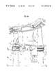
- FIG. 1 ais a partial longitudinal section illustrating a two-stage high-pressure turbine the stage-1 rotor disk of which in a first embodiment carries blades in accordance with the present invention
- FIG. 1 bis a sectional view along A—A from FIG. 1 a,
- FIG. 1 cis a perspective partial view of a lock-plate securing the blades in position on the rotor disk
- FIG. 2 areflects the arrangement of FIG. 1 a and illustrates blades designed in accordance with a second embodiment
- FIG. 2 bis a sectional view along B—B from FIG. 2 a,
- FIG. 3 areflects the arrangement of FIG. 1 a and illustrates blades designed in accordance with a third embodiment
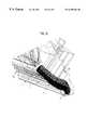
- FIG. 3 bis a sectional view along C—C from FIG. 3 a .
- FIG. 3 cis a perspective view of the cooling air duct extending turbine-fashion through the blade root in accordance with FIGS. 3 a and 3 b.
- Reference numeral 8 in all drawingsindicates the rotor disk of the first stage of an axial-flow high-pressure turbine of an aircraft engine, said disk being followed downstream by a stage-2 rotor disk 8 ′.
- Stage-1 rotor disk 8 and stage-2 rotor disk 8 ′each carry in the normal manner a plurality of circumferentially spaced turbine rotor blades 2 and 2 ′ respectively, (hereafter briefly called blades 2 , 2 ′), projecting into an annular duct 11 which conducts the working gas of the turbomachine in the direction of arrowhead 10 .
- Blades 2 and 2 ′are attached to their disks 8 and 8 ′, respectively, in the normal manner. Viewed in the downstream direction 10 , blades 2 , 2 ′ have fir-tree roots 1 and 1 ′ respectively, by which blades 2 and 2 ′ are seated in correspondingly contoured recesses in the disks 8 , 8 ′. Suitably designed lock-plates 3 , 3 ′ attached to rotor disks 8 , 8 ′ keep blades 2 , 2 ′ from slipping axially (in the direction of arrowhead 10 ).
- blades 2 , 2 ′are cooled, i.e. at least one cooling duct 17 issues through a plurality of effusion holes onto the surface of blades 2 , 2 ′ that conduct or are energized by the working gas.
- Said cooling duct 17is supplied with air from cooling air chamber 7 provided inside the blade root (which here is shown only for blade root 1 ), i.e. at least one cooling duct branches off from cooling air chamber 7 .
- This cooling air chamber 7is supplied with cooling air through a feed duct 15 in rotor disk 8 , which starts at upstream face 8 a of rotor disk 8 , viewed in the direction of flow 10 , and issues into an unnumbered recess receiving blade root 1 in rotor disk 8 .
- the radially ( 16 ) inner wall 8 b of rotor disk 8 confining said recessconfines the cooling air chamber 7 at its radially ( 16 ) inner end, the chamber otherwise being confined by the blade root 1 into which it is recessed.
- a compressor upstream of the axial-flow high-pressure turbinesupplies cooling air in a manner not shown in the drawing to the inlet port of feed duct 15 in the upstream face 8 a , this being internal cooling air as previously described.
- This cooling air flowpart of which is ducted in a manner yet to be described through blade root 1 in the direction of flow 10 , is indicated by unnumbered arrowheads.
- Branching off from cooling chamber 7is, besides the at least one cooling duct 17 which issues onto the surface of blade 2 in annular duct 11 through said effusion holes, an additional cooling air duct 4 which extends entirely inside blade root 1 and, without ever reaching into that portion of blade 2 which projects into annular duct 11 , issues at the back 1 a of blade root 1 , viewed in the direction of flow 10 .
- cooling air duct 4Through said cooling air duct 4 , a portion of the cooling air flow being supplied to the inlet port of feed duct 15 in upstream face 8 a of rotor disk 8 , can reach a space 6 arranged between rotor disks 8 and 8 ′, from where in a manner not illustrated (although similar to that used for stage-1 rotor disk 8 ) it is directed to and into blade 2 ′ of stage-2 rotor disk 8 ′.
- cooling air duct 4 inside blade root 1issues directly into space 6 , i.e. the outlet port 5 of cooling air duct 4 is arranged in the back 1 a of blade root 1 .
- the cooling air ductsubsequently continues from the back 1 a of blade root 1 in said lock-plate 3 and issues into space 6 through an outlet port 5 at the back of said plate facing away from blade root 1 .
- cooling air duct 4extends in all embodiments substantially continuously from cooling air chamber 7 to outlet port 5 , deflecting the cooling air flow inside it and taking a preferably convergent shape. Deflection of the cooling air flow itself, plus the essentially continuous passage, causes the cooling air ducts 4 provided in each blade 1 of rotor disk 8 to form, as a result of their appreciable length in conjunction with the fact that blade 1 and rotor disk 8 rotate about axis of rotation 14 , a so-alled axial-flow microturbine. This characteristic causes the cooling air flow inside cooling air ducts 4 to gradually cool on its way from cooling air chamber 7 to outlet port 5 . This constitutes an essential and desirable effect of the cooling air ducts 4 designed in the manner described above.
- stage-1 rotor disk 8The cooling of that portion of the air flow which is ducted to rotor disk 8 through blade roots 1 of stage-1 rotor disk 8 is advantageous for the reason that the cooling air flow subsequently reaching space 6 to cool stage-2 rotor disk 8 ′ is cooler than it would otherwise be, if the cooling air ducts in the stage-1 blades 2 on stage-1 rotor disk 8 had not been designed as described.
- each cooling air duct 4is given a shape that converges from cooling air chamber 7 toward outlet port 5 , so that the cooling air flow through cooling air duct 4 is accelerated to improve the cooling effect.
- This puts the throat section of cooling air duct 4as is the case with flow ducts in reaction turbines, near outlet port 5 .
- cooling air duct 4is designed to the rules applying for axial-flow reaction turbines, so that a realistic axial-flow microturbine actually results.
- FIG. 3 cis a perspective view showing such a cooling air duct 4 extending in blade root 1 , especially the duct depicted in FIGS. 3 a , 3 b . Plainly apparent from this FIG. 3 c is, apart from said cooling air duct 4 , the cooling air chamber 7 and to the left- and right-hand sides of it the contours 1 b of fir-tree blade root 1 .
- Outlet port 5 of cooling air duct 4is preferably designed such that the cooling air flow issuing from outlet port 5 has a velocity component directed counter to the direction of rotation of blades 2 in the turbomachine or axial-flow high-pressure turbine. This applies equally to the embodiment of FIG. 3 a and those of FIGS. 1 a , 2 a , where outlet port 5 of cooling air duct 4 as it exits from lock-plate 3 is designed such that the issuing cooling air flow has a velocity component counter to the direction of rotation of rotor disk 8 .
- This design of outlet port 5becomes apparent in the various embodiments from FIGS.
- the optimized aerodynamic flow through continuous, convergent cooling air duct 4 and its deflection thereinwill in an application of the present invention cool this flow by about 100° on an absolute temperature scale.
- Optimized natural deflection and relief of the cooling air flow through axial-flow microturbine cooling air flow ducts 4accordingly achieve, by a simple construction and with no need for additional components, an excellent cooling effect on rotor disk 8 ′ downstream of rotor disk 8 or on further stages of the axial-flow high-pressure turbine.
- the design of blade 2 or rotor disk 8 as described aboveis not limited to axial-flow high-pressure turbines, but naturally is applicable to turbomachines generally.
- lock-plate 3is designed, in the convergent portion of cooling air duct 4 , wide enough so that the portion of cooling air duct 4 inside lock-plate 3 is long enough to deflect the cooling air stream.
- the convergent portion of cooling air duct 4is substantially in lock-plate 3 , while the portion of cooling air duct 4 extending in blade root 1 proper is made less convergent.
Landscapes
- Engineering & Computer Science (AREA)
- Mechanical Engineering (AREA)
- General Engineering & Computer Science (AREA)
- Chemical & Material Sciences (AREA)
- Combustion & Propulsion (AREA)
- Turbine Rotor Nozzle Sealing (AREA)
Abstract
Description
Claims (8)
Applications Claiming Priority (2)
| Application Number | Priority Date | Filing Date | Title |
|---|---|---|---|
| DE19854908 | 1998-11-27 | ||
| DE19854908ADE19854908A1 (en) | 1998-11-27 | 1998-11-27 | Blade and rotor of a turbomachine |
Publications (1)
| Publication Number | Publication Date |
|---|---|
| US6290464B1true US6290464B1 (en) | 2001-09-18 |
Family
ID=7889311
Family Applications (1)
| Application Number | Title | Priority Date | Filing Date |
|---|---|---|---|
| US09/449,836Expired - LifetimeUS6290464B1 (en) | 1998-11-27 | 1999-11-26 | Turbomachine rotor blade and disk |
Country Status (4)
| Country | Link |
|---|---|
| US (1) | US6290464B1 (en) |
| EP (1) | EP1004748B1 (en) |
| AT (1) | ATE531898T1 (en) |
| DE (1) | DE19854908A1 (en) |
Cited By (28)
| Publication number | Priority date | Publication date | Assignee | Title |
|---|---|---|---|---|
| US20010056229A1 (en)* | 1999-04-16 | 2001-12-27 | Cardiocom | Apparatus and method for monitoring and communicating wellness parameters of ambulatory patients |
| US20060188377A1 (en)* | 2005-02-23 | 2006-08-24 | Dixon Jeffrey A | Lock plate arrangement |
| US20060216149A1 (en)* | 2004-10-26 | 2006-09-28 | Wilson Erich A | Fluid Flow Channels in Bladeless Compressors, Turbines and Pumps |
| US20060291997A1 (en)* | 2004-10-26 | 2006-12-28 | Wilson Erich A | Fluid Flow Chambers and Bridges in Bladeless Compressors, Turbines and Pumps |
| US20070073429A1 (en)* | 2002-04-26 | 2007-03-29 | Bae Systems Plc | Optimisation of the design of a component |
| US20070092369A1 (en)* | 2005-10-25 | 2007-04-26 | Erich Wilson | Bracket/Spacer Optimization in Bladeless Turbines, Compressors and Pumps |
| US20070217904A1 (en)* | 2006-03-14 | 2007-09-20 | Dixon Jeffrey A | Turbine engine cooling |
| EP1967692A2 (en) | 2007-03-09 | 2008-09-10 | Rolls-Royce Deutschland Ltd & Co KG | Turbine blade with microturbine nozzle fixed in blade root |
| US20100124483A1 (en)* | 2008-11-17 | 2010-05-20 | Rolls-Royce Corporation | Apparatus and method for cooling a turbine airfoil arrangement in a gas turbine engine |
| US20110110782A1 (en)* | 2009-11-11 | 2011-05-12 | General Electric Company | Locking spacer assembly for a circumferential entry airfoil attachment system |
| US8152436B2 (en) | 2008-01-08 | 2012-04-10 | Pratt & Whitney Canada Corp. | Blade under platform pocket cooling |
| FR2969209A1 (en)* | 2010-12-21 | 2012-06-22 | Snecma | Element e.g. downstream wall, for use in blade of rotor of turbine stage of e.g. twin spool turbine engine of aircraft, has multiperforation part for passage of flow of cooling air to upstream face of downstream flange |
| US20140072420A1 (en)* | 2012-09-11 | 2014-03-13 | General Electric Company | Flow inducer for a gas turbine system |
| US20140321961A1 (en)* | 2012-05-31 | 2014-10-30 | United Technologies Corporation | Mate face cooling holes for gas turbine engine component |
| US20160177755A1 (en)* | 2014-12-22 | 2016-06-23 | United Technologies Corporation | Hardware geometry for increasing part overlap and maintaining clearance |
| US20170138200A1 (en)* | 2015-07-20 | 2017-05-18 | Rolls-Royce Deutschland Ltd & Co Kg | Cooled turbine runner, in particular for an aircraft engine |
| US20170268380A1 (en)* | 2016-03-17 | 2017-09-21 | Rolls-Royce Deutschland Ltd & Co Kg | Cooling device for cooling platforms of a guide vane ring of a gas turbine |
| US20180328195A1 (en)* | 2017-05-09 | 2018-11-15 | Rolls-Royce Deutschland Ltd & Co Kg | Rotor device of a turbomachine |
| US10196895B2 (en) | 2015-07-20 | 2019-02-05 | Rolls-Royce Deutschland Ltd & Co Kg | Cooled turbine runner for an aircraft engine |
| US10378372B2 (en) | 2015-07-21 | 2019-08-13 | Rolls-Royce Deutschland Ltd & Co Kg | Turbine with cooled turbine guide vanes |
| CN110168198A (en)* | 2017-01-09 | 2019-08-23 | 康明斯滤清系统知识产权公司 | Blow down turbine with the non-wetted surface for improving hydraulic efficiency |
| US10619490B2 (en) | 2016-12-19 | 2020-04-14 | Rolls-Royce Deutschland Ltd & Co Kg | Turbine rotor blade arrangement for a gas turbine and method for the provision of sealing air in a turbine rotor blade arrangement |
| US20200200024A1 (en)* | 2018-12-21 | 2020-06-25 | Rolls-Royce Plc | Turbine section of a gas turbine engine with ceramic matrix composite vanes |
| CN112585334A (en)* | 2018-09-04 | 2021-03-30 | 赛峰航空器发动机 | Rotor disk with axially fixed blades, assembly of disk and ring, and turbomachine |
| US11053808B2 (en)* | 2013-12-12 | 2021-07-06 | Raytheon Technologies Corporation | Multiple injector holes for gas turbine engine vane |
| CN113339076A (en)* | 2020-03-03 | 2021-09-03 | 艾特帕新世代涡轮机有限责任公司 | Vane assembly for a gas turbine engine |
| US11143041B2 (en) | 2017-01-09 | 2021-10-12 | General Electric Company | Turbine have a first and second rotor disc and a first and second cooling fluid conduit wherein the second cooling fluid conduit is extended through an annular axially extended bore having a radially outer extent defined by a radially innermost surface of the rotor discs |
| US11499479B2 (en) | 2017-08-31 | 2022-11-15 | General Electric Company | Air delivery system for a gas turbine engine |
Families Citing this family (1)
| Publication number | Priority date | Publication date | Assignee | Title |
|---|---|---|---|---|
| DE102017212616A1 (en) | 2017-07-21 | 2019-01-24 | Rolls-Royce Deutschland Ltd & Co Kg | Nozzle assembly for a combustion chamber of an engine |
Citations (11)
| Publication number | Priority date | Publication date | Assignee | Title |
|---|---|---|---|---|
| DE906636C (en) | 1944-01-23 | 1954-03-15 | Herwig Kress Dr Ing | Gas or exhaust gas turbines with hollow blade cooling |
| US3791758A (en)* | 1971-05-06 | 1974-02-12 | Secr Defence | Cooling of turbine blades |
| GB2057573A (en) | 1979-08-30 | 1981-04-01 | Rolls Royce | Turbine rotor assembly |
| US4292008A (en)* | 1977-09-09 | 1981-09-29 | International Harvester Company | Gas turbine cooling systems |
| DE3210626A1 (en) | 1981-04-01 | 1982-11-18 | United Technologies Corp., 06101 Hartford, Conn. | AXIAL GAS TURBINE ENGINE |
| US4425079A (en)* | 1980-08-06 | 1984-01-10 | Rolls-Royce Limited | Air sealing for turbomachines |
| US4820116A (en)* | 1987-09-18 | 1989-04-11 | United Technologies Corporation | Turbine cooling for gas turbine engine |
| DE3835932A1 (en) | 1988-10-21 | 1990-04-26 | Mtu Muenchen Gmbh | DEVICE FOR COOLING AIR SUPPLY FOR GAS TURBINE ROTOR BLADES |
| US5795130A (en)* | 1995-11-24 | 1998-08-18 | Mitsubishi Jukogyo Kabushiki Kaisha | Heat recovery type gas turbine rotor |
| DE19705442A1 (en) | 1997-02-13 | 1998-08-20 | Bmw Rolls Royce Gmbh | Turbine impeller disk with cooling air channels |
| US6071075A (en)* | 1997-02-25 | 2000-06-06 | Mitsubishi Heavy Industries, Ltd. | Cooling structure to cool platform for drive blades of gas turbine |
Family Cites Families (4)
| Publication number | Priority date | Publication date | Assignee | Title |
|---|---|---|---|---|
| FR1207772A (en)* | 1957-07-18 | 1960-02-18 | Rolls Royce | Improvements to fluid machines with paddle rotors |
| BE791162A (en)* | 1971-11-10 | 1973-03-01 | Penny Robert N | TURBINE ROTOR |
| DE3736836A1 (en)* | 1987-10-30 | 1989-05-11 | Bbc Brown Boveri & Cie | AXIAL FLOWED GAS TURBINE |
| FR2707698B1 (en)* | 1993-07-15 | 1995-08-25 | Snecma | Turbomachine provided with an air blowing means on a rotor element. |
- 1998
- 1998-11-27DEDE19854908Apatent/DE19854908A1/ennot_activeWithdrawn
- 1999
- 1999-11-04ATAT99121823Tpatent/ATE531898T1/enactive
- 1999-11-04EPEP99121823Apatent/EP1004748B1/ennot_activeExpired - Lifetime
- 1999-11-26USUS09/449,836patent/US6290464B1/ennot_activeExpired - Lifetime
Patent Citations (12)
| Publication number | Priority date | Publication date | Assignee | Title |
|---|---|---|---|---|
| DE906636C (en) | 1944-01-23 | 1954-03-15 | Herwig Kress Dr Ing | Gas or exhaust gas turbines with hollow blade cooling |
| US3791758A (en)* | 1971-05-06 | 1974-02-12 | Secr Defence | Cooling of turbine blades |
| US4292008A (en)* | 1977-09-09 | 1981-09-29 | International Harvester Company | Gas turbine cooling systems |
| GB2057573A (en) | 1979-08-30 | 1981-04-01 | Rolls Royce | Turbine rotor assembly |
| US4425079A (en)* | 1980-08-06 | 1984-01-10 | Rolls-Royce Limited | Air sealing for turbomachines |
| DE3210626A1 (en) | 1981-04-01 | 1982-11-18 | United Technologies Corp., 06101 Hartford, Conn. | AXIAL GAS TURBINE ENGINE |
| US4820116A (en)* | 1987-09-18 | 1989-04-11 | United Technologies Corporation | Turbine cooling for gas turbine engine |
| DE3835932A1 (en) | 1988-10-21 | 1990-04-26 | Mtu Muenchen Gmbh | DEVICE FOR COOLING AIR SUPPLY FOR GAS TURBINE ROTOR BLADES |
| US5795130A (en)* | 1995-11-24 | 1998-08-18 | Mitsubishi Jukogyo Kabushiki Kaisha | Heat recovery type gas turbine rotor |
| DE19705442A1 (en) | 1997-02-13 | 1998-08-20 | Bmw Rolls Royce Gmbh | Turbine impeller disk with cooling air channels |
| US6022190A (en)* | 1997-02-13 | 2000-02-08 | Bmw Rolls-Royce Gmbh | Turbine impeller disk with cooling air channels |
| US6071075A (en)* | 1997-02-25 | 2000-06-06 | Mitsubishi Heavy Industries, Ltd. | Cooling structure to cool platform for drive blades of gas turbine |
Cited By (48)
| Publication number | Priority date | Publication date | Assignee | Title |
|---|---|---|---|---|
| US20010056229A1 (en)* | 1999-04-16 | 2001-12-27 | Cardiocom | Apparatus and method for monitoring and communicating wellness parameters of ambulatory patients |
| US20070073429A1 (en)* | 2002-04-26 | 2007-03-29 | Bae Systems Plc | Optimisation of the design of a component |
| US7751917B2 (en)* | 2002-04-26 | 2010-07-06 | Bae Systems Plc | Optimisation of the design of a component |
| US20060216149A1 (en)* | 2004-10-26 | 2006-09-28 | Wilson Erich A | Fluid Flow Channels in Bladeless Compressors, Turbines and Pumps |
| US20060291997A1 (en)* | 2004-10-26 | 2006-12-28 | Wilson Erich A | Fluid Flow Chambers and Bridges in Bladeless Compressors, Turbines and Pumps |
| US20060188377A1 (en)* | 2005-02-23 | 2006-08-24 | Dixon Jeffrey A | Lock plate arrangement |
| EP1703081A1 (en) | 2005-02-23 | 2006-09-20 | Rolls-Royce Plc | Side plate |
| US20070092369A1 (en)* | 2005-10-25 | 2007-04-26 | Erich Wilson | Bracket/Spacer Optimization in Bladeless Turbines, Compressors and Pumps |
| US7478990B2 (en) | 2005-10-25 | 2009-01-20 | Wilson Erich A | Bracket/spacer optimization in bladeless turbines, compressors and pumps |
| US7465149B2 (en) | 2006-03-14 | 2008-12-16 | Rolls-Royce Plc | Turbine engine cooling |
| US20070217904A1 (en)* | 2006-03-14 | 2007-09-20 | Dixon Jeffrey A | Turbine engine cooling |
| DE102007012320A1 (en) | 2007-03-09 | 2008-09-11 | Rolls-Royce Deutschland Ltd & Co Kg | Turbine blade with blade-formed microturbine nozzle |
| US20080219855A1 (en)* | 2007-03-09 | 2008-09-11 | Richard Whitton | Turbine blade with micro-turbine nozzle provided in the blade root |
| EP1967692A2 (en) | 2007-03-09 | 2008-09-10 | Rolls-Royce Deutschland Ltd & Co KG | Turbine blade with microturbine nozzle fixed in blade root |
| EP1967692A3 (en)* | 2007-03-09 | 2011-11-23 | Rolls-Royce Deutschland Ltd & Co KG | Turbine blade with microturbine nozzle fixed in blade root |
| US8152436B2 (en) | 2008-01-08 | 2012-04-10 | Pratt & Whitney Canada Corp. | Blade under platform pocket cooling |
| US20100124483A1 (en)* | 2008-11-17 | 2010-05-20 | Rolls-Royce Corporation | Apparatus and method for cooling a turbine airfoil arrangement in a gas turbine engine |
| US8408866B2 (en)* | 2008-11-17 | 2013-04-02 | Rolls-Royce Corporation | Apparatus and method for cooling a turbine airfoil arrangement in a gas turbine engine |
| US20110110782A1 (en)* | 2009-11-11 | 2011-05-12 | General Electric Company | Locking spacer assembly for a circumferential entry airfoil attachment system |
| US8523529B2 (en) | 2009-11-11 | 2013-09-03 | General Electric Company | Locking spacer assembly for a circumferential entry airfoil attachment system |
| FR2969209A1 (en)* | 2010-12-21 | 2012-06-22 | Snecma | Element e.g. downstream wall, for use in blade of rotor of turbine stage of e.g. twin spool turbine engine of aircraft, has multiperforation part for passage of flow of cooling air to upstream face of downstream flange |
| US10180067B2 (en)* | 2012-05-31 | 2019-01-15 | United Technologies Corporation | Mate face cooling holes for gas turbine engine component |
| US20140321961A1 (en)* | 2012-05-31 | 2014-10-30 | United Technologies Corporation | Mate face cooling holes for gas turbine engine component |
| US9435206B2 (en)* | 2012-09-11 | 2016-09-06 | General Electric Company | Flow inducer for a gas turbine system |
| US10612384B2 (en) | 2012-09-11 | 2020-04-07 | General Electric Company | Flow inducer for a gas turbine system |
| US20140072420A1 (en)* | 2012-09-11 | 2014-03-13 | General Electric Company | Flow inducer for a gas turbine system |
| US11053808B2 (en)* | 2013-12-12 | 2021-07-06 | Raytheon Technologies Corporation | Multiple injector holes for gas turbine engine vane |
| US11021976B2 (en)* | 2014-12-22 | 2021-06-01 | Raytheon Technologies Corporation | Hardware geometry for increasing part overlap and maintaining clearance |
| US20160177755A1 (en)* | 2014-12-22 | 2016-06-23 | United Technologies Corporation | Hardware geometry for increasing part overlap and maintaining clearance |
| US10196895B2 (en) | 2015-07-20 | 2019-02-05 | Rolls-Royce Deutschland Ltd & Co Kg | Cooled turbine runner for an aircraft engine |
| US10436031B2 (en)* | 2015-07-20 | 2019-10-08 | Rolls-Royce Deutschland Ltd & Co Kg | Cooled turbine runner, in particular for an aircraft engine |
| US20170138200A1 (en)* | 2015-07-20 | 2017-05-18 | Rolls-Royce Deutschland Ltd & Co Kg | Cooled turbine runner, in particular for an aircraft engine |
| US10378372B2 (en) | 2015-07-21 | 2019-08-13 | Rolls-Royce Deutschland Ltd & Co Kg | Turbine with cooled turbine guide vanes |
| US20170268380A1 (en)* | 2016-03-17 | 2017-09-21 | Rolls-Royce Deutschland Ltd & Co Kg | Cooling device for cooling platforms of a guide vane ring of a gas turbine |
| US10669886B2 (en)* | 2016-03-17 | 2020-06-02 | Rolls-Royce Deutschland Ltd & Co Kg | Cooling device for cooling platforms of a guide vane ring of a gas turbine |
| US10619490B2 (en) | 2016-12-19 | 2020-04-14 | Rolls-Royce Deutschland Ltd & Co Kg | Turbine rotor blade arrangement for a gas turbine and method for the provision of sealing air in a turbine rotor blade arrangement |
| CN110168198A (en)* | 2017-01-09 | 2019-08-23 | 康明斯滤清系统知识产权公司 | Blow down turbine with the non-wetted surface for improving hydraulic efficiency |
| US11143041B2 (en) | 2017-01-09 | 2021-10-12 | General Electric Company | Turbine have a first and second rotor disc and a first and second cooling fluid conduit wherein the second cooling fluid conduit is extended through an annular axially extended bore having a radially outer extent defined by a radially innermost surface of the rotor discs |
| US20180328195A1 (en)* | 2017-05-09 | 2018-11-15 | Rolls-Royce Deutschland Ltd & Co Kg | Rotor device of a turbomachine |
| US10738624B2 (en)* | 2017-05-09 | 2020-08-11 | Rolls-Royce Deutschland Ltd & Co Kg | Rotor device of a turbomachine |
| US11499479B2 (en) | 2017-08-31 | 2022-11-15 | General Electric Company | Air delivery system for a gas turbine engine |
| CN112585334A (en)* | 2018-09-04 | 2021-03-30 | 赛峰航空器发动机 | Rotor disk with axially fixed blades, assembly of disk and ring, and turbomachine |
| CN112585334B (en)* | 2018-09-04 | 2023-09-15 | 赛峰航空器发动机 | Rotor disk with axially fixed blades, disk and ring assembly, and turbine |
| US11486252B2 (en)* | 2018-09-04 | 2022-11-01 | Safran Aircraft Engines | Rotor disc with axial retention of the blades, assembly of a disc and a ring, and turbomachine |
| US20200200024A1 (en)* | 2018-12-21 | 2020-06-25 | Rolls-Royce Plc | Turbine section of a gas turbine engine with ceramic matrix composite vanes |
| US11047247B2 (en)* | 2018-12-21 | 2021-06-29 | Rolls-Royce Plc | Turbine section of a gas turbine engine with ceramic matrix composite vanes |
| CN113339076A (en)* | 2020-03-03 | 2021-09-03 | 艾特帕新世代涡轮机有限责任公司 | Vane assembly for a gas turbine engine |
| US11506072B2 (en) | 2020-03-03 | 2022-11-22 | Itp Next Generation Turbines S.L. | Blade assembly for gas turbine engine |
Also Published As
| Publication number | Publication date |
|---|---|
| DE19854908A1 (en) | 2000-05-31 |
| EP1004748A2 (en) | 2000-05-31 |
| ATE531898T1 (en) | 2011-11-15 |
| EP1004748A3 (en) | 2001-10-17 |
| EP1004748B1 (en) | 2011-11-02 |
Similar Documents
| Publication | Publication Date | Title |
|---|---|---|
| US6290464B1 (en) | Turbomachine rotor blade and disk | |
| US7004720B2 (en) | Cooled turbine vane platform | |
| US7200999B2 (en) | Arrangement for bleeding the boundary layer from an aircraft engine | |
| US6082966A (en) | Stator vane assembly for a turbomachine | |
| US5555721A (en) | Gas turbine engine cooling supply circuit | |
| US7192245B2 (en) | Rotor assembly with cooling air deflectors and method | |
| JP5279400B2 (en) | Turbomachine diffuser | |
| US10113486B2 (en) | Method and system for modulated turbine cooling | |
| US8784051B2 (en) | Strut for a gas turbine engine | |
| EP1892405A2 (en) | Gas turbine engine exhaust duct ventilation | |
| EP3196422B1 (en) | Exhaust frame | |
| US20090003987A1 (en) | Airfoil with improved cooling slot arrangement | |
| US11933193B2 (en) | Turbine engine with an airfoil having a set of dimples | |
| US20170211393A1 (en) | Gas turbine aerofoil trailing edge | |
| US11118475B2 (en) | Turbine shroud cooling | |
| CN109477394A (en) | Impingement cooling of the bucket platform | |
| EP3964716B1 (en) | Impeller exducer cavity with flow recirculation | |
| US10794215B2 (en) | Cooling arrangement for a turbine casing of a gas turbine engine | |
| EP3708804B1 (en) | Impeller tip cavity | |
| KR20120034670A (en) | Centrifugal impeller for compressor | |
| WO2017069201A1 (en) | Compressor rotor, gas turbine rotor provided therewith, and gas turbine | |
| CN110344943B (en) | Cooling structure for turbomachine component | |
| US10718267B2 (en) | Turbine engine cooling with substantially uniform cooling air flow distribution | |
| US11008871B2 (en) | Turbine blade of a turbine blade ring | |
| CN108691658B (en) | Turbine engine with platform cooling circuit |
Legal Events
| Date | Code | Title | Description |
|---|---|---|---|
| AS | Assignment | Owner name:BMW ROLLS-ROYCE GMBH, GERMANY Free format text:ASSIGNMENT OF ASSIGNORS INTEREST;ASSIGNORS:NEGULESCU, DIMITRIE;LOTZERICH, MICHAEL;REEL/FRAME:010583/0800;SIGNING DATES FROM 19991123 TO 19991203 | |
| STCF | Information on status: patent grant | Free format text:PATENTED CASE | |
| AS | Assignment | Owner name:ROLLS-ROYCE DEUTSCHLAND GMBH, GERMANY Free format text:CHANGE OF NAME;ASSIGNOR:BMW ROLLS-ROYCE GMBH;REEL/FRAME:013456/0139 Effective date:20000131 | |
| AS | Assignment | Owner name:ROLLS-ROYCE DEUTSCHLAND LTD & CO KG, GERMANY Free format text:CHANGE OF NAME;ASSIGNOR:ROLLS-ROYCE DEUTSCHLAND GMBH;REEL/FRAME:013184/0851 Effective date:20001115 | |
| AS | Assignment | Owner name:ROLLS-ROYCE DEUTSCHLAND GMBH, GERMANY Free format text:CHANGE OF NAME;ASSIGNOR:BMW ROLLS-ROYCE GMBH;REEL/FRAME:013221/0750 Effective date:20000131 | |
| AS | Assignment | Owner name:ROLLS-ROYCE DEUTSCHLAND LTD & CO KG, GERMANY Free format text:CHANGE OF NAME;ASSIGNOR:ROLLS-ROYCE DEUTSCHLAND GMBH;REEL/FRAME:014242/0250 Effective date:20001115 | |
| FEPP | Fee payment procedure | Free format text:PAYOR NUMBER ASSIGNED (ORIGINAL EVENT CODE: ASPN); ENTITY STATUS OF PATENT OWNER: LARGE ENTITY | |
| FPAY | Fee payment | Year of fee payment:4 | |
| FPAY | Fee payment | Year of fee payment:8 | |
| FPAY | Fee payment | Year of fee payment:12 |