US6289247B1 - Strategy selector for multichannel cochlear prosthesis - Google Patents
Strategy selector for multichannel cochlear prosthesisDownload PDFInfo
- Publication number
- US6289247B1 US6289247B1US09/322,712US32271299AUS6289247B1US 6289247 B1US6289247 B1US 6289247B1US 32271299 AUS32271299 AUS 32271299AUS 6289247 B1US6289247 B1US 6289247B1
- Authority
- US
- United States
- Prior art keywords
- strategy
- speech processing
- stimulation
- channels
- simultaneous
- Prior art date
- Legal status (The legal status is an assumption and is not a legal conclusion. Google has not performed a legal analysis and makes no representation as to the accuracy of the status listed.)
- Expired - Lifetime
Links
- 230000000638stimulationEffects0.000claimsabstractdescription253
- 238000012545processingMethods0.000claimsabstractdescription219
- 230000000541pulsatile effectEffects0.000claimsabstractdescription97
- 230000008878couplingEffects0.000claimsabstractdescription38
- 238000010168coupling processMethods0.000claimsabstractdescription36
- 238000005859coupling reactionMethods0.000claimsabstractdescription36
- 210000003477cochleaAnatomy0.000claimsabstractdescription19
- 230000000007visual effectEffects0.000claimsabstractdescription16
- 230000004936stimulating effectEffects0.000claimsabstractdescription9
- 230000002123temporal effectEffects0.000claimsabstractdescription5
- 238000000034methodMethods0.000claimsdescription39
- 230000002051biphasic effectEffects0.000claimsdescription34
- 230000006870functionEffects0.000claimsdescription32
- 238000004458analytical methodMethods0.000claimsdescription31
- 238000013507mappingMethods0.000claimsdescription22
- 230000005236sound signalEffects0.000claimsdescription15
- 238000010586diagramMethods0.000claimsdescription12
- 238000004040coloringMethods0.000claimsdescription5
- 230000004044responseEffects0.000claimsdescription5
- 238000010187selection methodMethods0.000claimsdescription4
- 230000035807sensationEffects0.000claimsdescription4
- 108091006146ChannelsProteins0.000claims69
- 230000008569processEffects0.000description20
- 239000007943implantSubstances0.000description15
- 238000010304firingMethods0.000description12
- 230000006835compressionEffects0.000description11
- 238000007906compressionMethods0.000description11
- 238000012360testing methodMethods0.000description11
- 210000004027cellAnatomy0.000description8
- 230000035945sensitivityEffects0.000description8
- 230000008859changeEffects0.000description7
- 238000004891communicationMethods0.000description7
- 238000005259measurementMethods0.000description7
- 238000013459approachMethods0.000description6
- 230000008901benefitEffects0.000description6
- 238000001514detection methodMethods0.000description6
- 238000003491arrayMethods0.000description5
- 230000000694effectsEffects0.000description5
- 230000010354integrationEffects0.000description5
- 230000001537neural effectEffects0.000description5
- 210000002569neuronAnatomy0.000description5
- 238000005070samplingMethods0.000description5
- 238000001228spectrumMethods0.000description5
- 230000005284excitationEffects0.000description4
- 230000009286beneficial effectEffects0.000description3
- 230000005540biological transmissionEffects0.000description3
- 230000003247decreasing effectEffects0.000description3
- 238000001914filtrationMethods0.000description3
- 230000007246mechanismEffects0.000description3
- 235000001968nicotinic acidNutrition0.000description3
- 239000000047productSubstances0.000description3
- 241000321369Cephalopholis fulvaSpecies0.000description2
- 206010011878DeafnessDiseases0.000description2
- 230000003993interactionEffects0.000description2
- 238000012986modificationMethods0.000description2
- 230000004048modificationEffects0.000description2
- 230000008447perceptionEffects0.000description2
- 238000012163sequencing techniqueMethods0.000description2
- 238000004088simulationMethods0.000description2
- 238000012546transferMethods0.000description2
- 102100039384Huntingtin-associated protein 1Human genes0.000description1
- 101710140977Huntingtin-associated protein 1Proteins0.000description1
- 230000003213activating effectEffects0.000description1
- 230000015556catabolic processEffects0.000description1
- 210000000860cochlear nerveAnatomy0.000description1
- 230000000052comparative effectEffects0.000description1
- 239000004020conductorSubstances0.000description1
- 238000006731degradation reactionMethods0.000description1
- 230000000763evoking effectEffects0.000description1
- 230000002045lasting effectEffects0.000description1
- 238000012423maintenanceMethods0.000description1
- 230000008035nerve activityEffects0.000description1
- 210000000653nervous systemAnatomy0.000description1
- 239000011295pitchSubstances0.000description1
- 230000000750progressive effectEffects0.000description1
- 230000008672reprogrammingEffects0.000description1
- 230000002441reversible effectEffects0.000description1
- 210000001079scala tympaniAnatomy0.000description1
- 238000011451sequencing strategyMethods0.000description1
- 210000001323spiral ganglionAnatomy0.000description1
- 239000013589supplementSubstances0.000description1
- 230000001131transforming effectEffects0.000description1
Images


Classifications
- A—HUMAN NECESSITIES
- A61—MEDICAL OR VETERINARY SCIENCE; HYGIENE
- A61N—ELECTROTHERAPY; MAGNETOTHERAPY; RADIATION THERAPY; ULTRASOUND THERAPY
- A61N1/00—Electrotherapy; Circuits therefor
- A61N1/18—Applying electric currents by contact electrodes
- A61N1/32—Applying electric currents by contact electrodes alternating or intermittent currents
- A61N1/36—Applying electric currents by contact electrodes alternating or intermittent currents for stimulation
- A61N1/372—Arrangements in connection with the implantation of stimulators
- A61N1/37211—Means for communicating with stimulators
- A61N1/37235—Aspects of the external programmer
- A61N1/37247—User interfaces, e.g. input or presentation means
- A—HUMAN NECESSITIES
- A61—MEDICAL OR VETERINARY SCIENCE; HYGIENE
- A61N—ELECTROTHERAPY; MAGNETOTHERAPY; RADIATION THERAPY; ULTRASOUND THERAPY
- A61N1/00—Electrotherapy; Circuits therefor
- A61N1/18—Applying electric currents by contact electrodes
- A61N1/32—Applying electric currents by contact electrodes alternating or intermittent currents
- A61N1/36—Applying electric currents by contact electrodes alternating or intermittent currents for stimulation
- A61N1/36036—Applying electric currents by contact electrodes alternating or intermittent currents for stimulation of the outer, middle or inner ear
- A61N1/36038—Cochlear stimulation
- A—HUMAN NECESSITIES
- A61—MEDICAL OR VETERINARY SCIENCE; HYGIENE
- A61N—ELECTROTHERAPY; MAGNETOTHERAPY; RADIATION THERAPY; ULTRASOUND THERAPY
- A61N1/00—Electrotherapy; Circuits therefor
- A61N1/02—Details
- A61N1/04—Electrodes
- A61N1/05—Electrodes for implantation or insertion into the body, e.g. heart electrode
- A61N1/0526—Head electrodes
- A61N1/0541—Cochlear electrodes
- A—HUMAN NECESSITIES
- A61—MEDICAL OR VETERINARY SCIENCE; HYGIENE
- A61N—ELECTROTHERAPY; MAGNETOTHERAPY; RADIATION THERAPY; ULTRASOUND THERAPY
- A61N1/00—Electrotherapy; Circuits therefor
- A61N1/18—Applying electric currents by contact electrodes
- A61N1/32—Applying electric currents by contact electrodes alternating or intermittent currents
- A61N1/36—Applying electric currents by contact electrodes alternating or intermittent currents for stimulation
- A61N1/36036—Applying electric currents by contact electrodes alternating or intermittent currents for stimulation of the outer, middle or inner ear
- A61N1/36038—Cochlear stimulation
- A61N1/36039—Cochlear stimulation fitting procedures
Definitions
- the present inventionrelates to multichannel cochlear prosthesis, and more particularly to a multichannel cochlear prosthesis that offers selectable and flexible control of a full spectrum of stimulus waveforms that are applied to the cochlea through each of the channels of the system.
- Cochlear prosthesesproduce sensations of sound in deaf patients by direct electrical stimulation of the auditory nerve.
- several different sitesare stimulated at various distances along the cochlea to evoke the different pitches of sound perception that are normally encoded by nerve activity originating from the respective sites.
- the patterns of electrical stimulationare derived from acoustic signals picked up by a microphone and transformed by a so-called speech processor that is programmed to meet the particular requirements of each patient.
- Several different schemes for processing the acoustic signal and transforming it into electrical stimulihave been developed and are well-described in the scientific literature and various patents. These schemes can generally be divided into two basic types on the basis of the waveforms of the electrical stimuli:
- Analog waveformswhich are essentially filtered versions of the continuous acoustic waveform, usually involving dynamic range compression, bandpass filtering and scaling to the stimulus current ranges that evoke a satisfactory range of auditory sensations from threshold of perception to maximal comfortable loudness. This produces a rich but poorly controlled set of resultant waveforms because, inter alia, the waveforms are susceptible to degradation by an electrode array that does not have fully isolated channels.
- Biphasic pulsesconsist of a single cycle of a pulsed wave in which current flows in one direction at a specified magnitude and for a specified brief period of time and is followed immediately by an opposite direction of current of a similar magnitude and duration.
- Multiphasic pulsescomprise a plurality of pulsed waves in which current flows first in one direction, then in another direction, and so on, as required, at specified magnitudes and brief periods of time, in such a way that the charge associated with the total of all the plural pulses is balanced, whereby the net electrical charge delivered to the tissue over one multiphasic cycle is zero.
- biphasic or multiphasic pulsesare most often delivered in sequence to various sites, with the instantaneous magnitude at each site proportional to some measure of the amount of energy present in a particular frequency band of the acoustic waveform. The result is an impoverished (in terms of bandwidth and phase) but precisely controlled set of stimulus waveforms.
- the spatiotemporal manner in which either of the above two types of stimulus waveforms are applied to the cochlea of a patientis referred to as a “speech processing strategy.”
- the spatial application of the stimulus waveformsis controlled by the type of electrode coupling, e.g., bipolar or monopolar, through which the stimuli are applied to various locations along the inside of the scala tympani duct of the spiral-shaped cochlea.
- the temporal application of the stimulation waveformsis derived by the timing of the stimuli.
- speech processing strategieshave thus been classified as either: (1) a simultaneous strategy, or (2) a non-simultaneous, or sequential, strategy.
- Analog waveformshave traditionally been applied as part of a simultaneous strategy, relying on the more highly focused stimulation provided by bipolar coupling to produce an electrical pattern that will yield speech intelligibility.
- Short, non-simultaneous, biphasic or multiphasic pulsesare usually applied as part of a sequential speech processing strategy, relying on the highly precise sequence of stimulation pulses through monopolar coupling to produce the electrical pattern that yields speech intelligibility.
- short biphasic pulsesare applied in rapid succession (with little or no time overlap) in a specified pattern to each of multiple channels.
- a cochlear prosthesisWhen a cochlear prosthesis is first provided to a patient, including implanting any implantable components of the prosthesis into the patient (which implantable components typically include at least an electrode and a stimulator, and may also include, for fully implantable systems, a speech processor, a microphone and/or a rechargeable power source), it is necessary to initially “fit” or “adjust” the prosthesis.
- implantable componentstypically include at least an electrode and a stimulator, and may also include, for fully implantable systems, a speech processor, a microphone and/or a rechargeable power source
- the terms “fit”, “adjust”, “fitting” or “adjusting”relate to making electronic or software-programming changes to the prosthesis, as opposed to making physical or hardware changes, for the purpose of making the prosthesis better perform its intended function of helping the deaf patient to sense sound.
- cochlear prosthesisare capable of providing more than one speech processing strategy, or of providing both simultaneous and non-simultaneous speech processing strategies. Rather, most commercially-available cochlear prosthesis provide just one type of strategy (simultaneous or non-simultaneous), although some may offer, for example, multiple non-simultaneous strategies. Hence, with these one-type-strategy devices, the patient, and/or the physician/audiologist fitting the patient, has no, or only a very limited, ability to select a suitable speech processing strategy that is most effective for that patient.
- the Clarions cochlear stimulatoravailable from Advanced Bionics Corporation, of Sylmar California, is the only known commercially-available cochlear stimulator that allows the user to select either a simultaneous speech processing strategy or a non-simultaneous speech processing strategy as the technique for encoding the acoustic input signal into an electrical pattern that yields speech intelligibility.
- the Clarion® stimulatoris described, inter alia, in U.S. Pat. No 5,603,726, which patent is incorporated herein by reference.
- any number N of these M pulsatile channelsmay be selected as the number of maxima.
- the speech processing strategythen applies a suitable algorithm to determine which N of the M channels are to be stimulated per data frame. Typically, the N channels with the greatest input levels are selected for stimulation. See, e.g., Wilson, et al., “ Comparative Studies of Speech Processing Strategies For Cochlear Implants ⁇ .
- the present inventionadvantageously addresses the above and other needs.
- the present inventionprovides a universal method and/or system whereby multiple speech processing strategies can be easily and quickly selected and modified for application to a patient having a multichannel implantable cochlear prosthesis.
- Such universal strategy selection method and/or systemadvantageously allows an audiologist or clinician to easily select and then test various speech processing strategies during the process of fitting such multichannel cochlear prosthesis.
- an easy-to-understand selection displayor selection screen, that provides a graphical representation of the stimulation waveforms associated with each channel of the selected strategy, a graphical representation of the electrode configuration pairing (also referred to herein as “electrode coupling”, which may include multipolar virtual, bipolar, or monopolar coupling) used to apply the selected strategy, as well as a visual presentation of other selection criteria, such as the degree of simultaneity, the ratio or number of analog channels to pulsatile channels, the number of maxima, the firing order (i.e., sequence of stimulation of the various channels), the number of analysis channels, the number of stimulator channels, and the repetition rate per channel.
- the selected speech processing strategyis selected from all of the different speech processing strategies made available within the particular multichannel cochlear prosthesis.
- the multichannel cochlear prosthesiscomprises a Clarion®-type cochlear prosthesis, which offers the capability of providing both simultaneous and non-simultaneous (sequential) speech processing strategies
- the selected speech processing strategymay be made from all possible speech processing strategies—ranging from simultaneous analog strategies on one end of the spectrum to non-simultaneous pulsatile strategies on the other end of the spectrum.
- the selected speech processing strategymay be made from all of the possible speech processing strategies ofthat type, e.g., a selection from all of the available sequential speech processing strategies.
- the selection of the speech processing strategy, from whatever group or collection of speech processing strategies is available within the multichannel cochlear prosthesis,is coupled with other useful information regarding the selection.
- Such other useful informationmay include, for example, an easy-to-understand selection display, a graphical representation of the stimulation waveforms associated with each channel of the selected strategy, a graphical representation of the electrode coupling, and/or a visual presentation of other selection criteria, such as degree of simultaneity, ratio or number of analog channels to pulsatile channels, number of maxima, firing order, number of analysis channels, number of stimulator channels, and/or repetition rate per channel.
- selection criteriasuch as degree of simultaneity, ratio or number of analog channels to pulsatile channels, number of maxima, firing order, number of analysis channels, number of stimulator channels, and/or repetition rate per channel.
- the inventionmay thus be characterized as a universal strategy selector for use with a multichannel cochlear prosthesis.
- the multichannel cochlear prosthesisincludes multiple stimulation channels through which a specific pattern of electrical stimulation, modulated by acoustic signals, and in accordance with a selected speech processing strategy, may be spatiotemporally applied to the cochlea in order to yield speech intelligibility.
- the universal strategy selectorincludes: (a) a processor, or equivalent; (b) a selector; and (c) a display.
- the processorincludes appropriate processing means coupled to the multichannel cochlear prosthesis for defining one of a plurality of speech processing strategies for use by the multichannel cochlear prosthesis.
- the processing meanswill be realized using a personal computer (PC), or a palm personal computer (PPC), programmed with appropriate software.
- the multiplicity of speech processing strategies that may be selectedincludes at least one speech processing strategy that is a simultaneous speech processing strategy, such as a simultaneous analog sampler (SAS) strategy; and at least one other speech processing strategy that is a non-simultaneous speech processing strategy, such as a continuous interleaved sampler (CIS) strategy.
- SASsimultaneous analog sampler
- CIScontinuous interleaved sampler
- the other speech processing strategies included within the multiplicity of strategiesinclude one or more strategies whose temporal characteristics lie somewhere in between simultaneous or non-simultaneous, and whose stimulating waveform(s) comprises a hybrid combination of analog or pulsatile waveforms.
- the multiplicity of speech processing strategies that may be selectedinclude speech processing strategies of the same type, e.g., different types or variations of pulsatile sequential strategies.
- the selectorcomprises a switch, pointer, or other selection means, for manually selecting one of the multiplicity of speech processing strategies as the selected speech processing strategy.
- the displaywhich is controlled by the processing means, provides a graphical or visual representation that characterizes the selected speech processing strategy in terms of the degree of simultaneity of the applied stimuli, as evident from representative stimulation waveforms (e.g., pulse patterns) and electrode coupling (e.g., bipolar or monopolar) for each channel, as well as other stimulation parameters (e.g., number of maxima, number of channels, firing order, repetition rate, and the like).
- representative stimulation waveformse.g., pulse patterns
- electrode couplinge.g., bipolar or monopolar
- other stimulation parameterse.g., number of maxima, number of channels, firing order, repetition rate, and the like.
- the list ofpossible speech processing strategies from which a selection is madelists the available speech processing strategies in a logical or progressive order relative to a particular characteristic of the stimulation.
- one characteristic of interestmay be the degree of simultaneity of the strategy, in which case the list of available speech processing strategies would place a simultaneous speech processing strategy (e.g., SAS) on one end of the list, e.g., the top of the list, and would place a non-simultaneous strategy (e.g., CIS) on the other end of the list, e.g., the bottom of the list.
- simultaneous speech processing strategye.g., SAS
- a non-simultaneous strategye.g., CIS
- Other characteristics of interestthat may be used to order the list of possible speech processing strategies, particularly where only pulsatile speech processing strategies are available, may include, e.g., the number of maxima, firing order, pulse repetition rate, pulse width, or the like.
- the number of maxima associated with pulsatile stimulation strategiesmay be selected along with the selection of the speech processing strategy, which speech processing strategies include both simultaneous and non-simultaneous strategies.
- the selected speech processing strategyincludes Mpulsatile channels out of L total channels
- any number N of these M pulsatile channels, where N is thus an integer from 1 to Mmay be selected as the number of maxima (referred to herein as “NofM”).
- the processor that defines the speech processing strategythen applies an appropriate algorithm to determine which N of the M channels are stimulated per data frame.
- the N channels with the greatest input levelsmay be selected for stimulation.
- the graphical representation of the electrode couplingis presented by displaying a drawing of the electrode array, with each electrode contact of the array being included in the drawing (with the exception of a common return electrode, if used), and with shading or distinctive coloring being used in the display to clearly depict which electrode contacts are paired together for stimulation.
- electrode array drawingpresented on the selection screen along side the other selection criteria, thus unequivocally conveys to the individual performing the selection process exactly what type of electrode coupling will result from a given selection.
- information defining the speech processing strategyis conveyed to characterize the speech processing strategy in terms of its degree of simultaneity, number of analog/pulsatile channels, pulse pattern, number of maxima, electrode coupling, firing order, number of channels, envelope detection/channel, repetition rate, or the like.
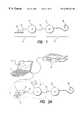
- FIG. 1shows a generalized block diagram of a cochlear stimulation system, including a microphone, a speech processor (SP), an implantable cochlear stimulator (ICS) and an electrode array;
- SPspeech processor
- ICSimplantable cochlear stimulator
- FIG. 2Adepicts the elements of a typical fitting system used with the cochlear stimulation system of FIG. 1;
- FIG. 2Bdepicts the elements of an alternate fitting system
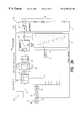
- FIG. 3Ais a functional block diagram of one channel of the speech processor and ICS portions of a multichannel cochlear stimulation system
- FIG. 3Bdepicts a typical filter response of the bandpass filter used in most of the channels of the speech processor of a multichannel cochlear stimulation system
- FIG. 3Cpresents a preferred frequency map for the filter bank used within the speech processor for two different speech processing strategies
- FIG. 3Dshows a preferred channel compression transfer function used within each channel of the speech processor of a multichannel cochlear stimulation system
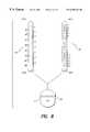
- FIG. 3Eshows how multiple analysis channels in the speech processor may be mapped with multiple stimulator channels in the cochlear stimulator in order to provide multiple neural excitation sites
- FIG. 4shows the makeup of a data frame that may be used, in one embodiment of the invention, to transfer information from an external speech processor (SP) to an implantable cochlear stimulator (ICS);
- SPexternal speech processor
- ICSimplantable cochlear stimulator
- FIG. 5illustrates how multiple data frames may be used with the cochlear stimulation system in order to achieve a desired stimulation pattern that repeats itself in cycles;
- FIG. 6illustrates a stimulation template that may be used with the invention to produce one form of a continuous interleaved sampler (CIS) speech processing strategy that provides a CIS stimulation pattern for an eight-channel cochlear stimulator;
- CIScontinuous interleaved sampler
- FIG. 7illustrates a stimulation template that may be used with the invention to produce a paired pulsatile sampler (PPS) speech processing strategy that provides a PPS stimulation pattern for an eight-channel cochlear stimulator;
- PPSpaired pulsatile sampler
- FIG. 8schematically illustrates two types of electrode arrays that may be used with an ICS, wherein by way of example each electrode array has sixteen individual electrode contacts, and wherein a common or reference electrode contact is provided on the case of the ICS;
- FIG. 9shows a representative selection screen display provided on a personal computer (PC), or equivalent device, by the invention to facilitate selection of one of a multiplicity of speech selection strategies, ranging from a simultaneous speech processing strategy, e.g., SAS, to a non-simultaneous speech processing strategy, e.g., CIS, and illustrates the various features associated with such selection screen;
- a simultaneous speech processing strategye.g., SAS
- a non-simultaneous speech processing strategye.g., CIS
- FIG. 10shows a representative screen display provided by the invention when an SAS strategy is selected, wherein analog stimulation waveforms are applied to all channels simultaneously;
- FIG. 11illustrates the representative screen display provided by the invention when a simultaneous pulsatile sampler (SPS) strategy is selected, wherein biphasic pulses are applied to all channels simultaneously;
- SPSsimultaneous pulsatile sampler
- FIG. 12similarly depicts the representative screen display provided by the invention when a hybrid analog pulsatile (HAP-4) strategy is selected that provides a simultaneous analog strategy on four channels and a sequential CIS-type pulsatile strategy on four channels, of an eight channel cochlear stimulation system;
- HAP-4hybrid analog pulsatile
- FIG. 13likewise shows the representative screen display provided by the invention when one type of a multiple pulsatile sample (MPS) strategy is selected, the selected strategy shown comprising a quad pulsatile sampler (QPS) strategy wherein biphasic pulses are alternately applied to four channels simultaneously;
- MPSmultiple pulsatile sample
- QPSquad pulsatile sampler
- FIG. 14depicts the screen display provided by the invention when a continuous interleaved sampler (CIS) strategy is applied wherein biphasic pulses are applied in sequence to eight channels, without time overlap, thereby providing a fully non-simultaneous, or sequential, strategy;
- CIScontinuous interleaved sampler
- FIG. 15shows a representative window mapping screen display that may be selected and used by the audiologist or other personnel during a fitting session.
- FIG. 16similarly shows a representative output adjustment screen display that may be selected and used by the audiologist or other personnel during a fitting session.
- a multichannel cochlear implant systemalso referred to as a cochlear stimulation system
- a cochlear stimulation systemthat has the capability of selectively generating both simultaneous and non-simultaneous (i.e., sequential) speech processing strategies
- the invention set forth in the claimsis not intended to be so limited. Rather, any multichannel cochlear implant system that is capable of generating a plurality of speech processing strategies, e.g., a plurality of pulsatile, non-simultaneous strategies, or a plurality of simultaneous strategies, one of which must be selected during a “fitting” operation, may benefit from application of the present invention.
- the inventionis not limited to the Clarion® cochlear implant system, per se. Rather, the invention is directed to a particular system, or method, of allowing one of a plurality of speech processing strategies to be selected during a fitting session.
- the Clarion® systemis referenced and described herein as just one example of how the best mode of the invention may be implemented.
- a cochlear stimulation systemthat includes a speech processor portion 10 and a cochlear stimulation portion 12 .
- the speech processor portion 10includes a speech processor (SP) 16 and a microphone 18 .
- the microphone 18may be connected directly to the SP 16 , or may be coupled to the SP 16 through an appropriate communication link 24 .
- the cochlear stimulation portion 12includes an implantable cochlear stimulator (ICS) 21 , and an electrode array 48 .
- the electrode array 48is adapted to be inserted within the cochlea of a patient.
- the array 48includes a multiplicity of electrodes, e.g., sixteen electrodes, spaced along its length that are selectively connected to the ICS 21 .
- the electrode array 48“Cochlear Electrode Array With Electrode Contacts on Medial Side”, also incorporated herein by reference.
- Electronic circuitry within the ICS 21allows a specified stimulation current to be applied to selected pairs or groups of the individual electrodes included within the electrode array 48 in accordance with a specified stimulation pattern, defined by the SP 16 .
- the ICS 21 and the SP 16are linked together electronically through a suitable communications link 14 that allows power and control signals to be sent from the SP 16 to the ICS 21 , and that (in some embodiments) allows data and status signals to be sent from the ICS 21 to the SP 16 .
- the details of such communication link 14are not important for purposes of the present invention.
- the link 14may be realized by an antenna coil in the ICS and an external antenna coil coupled to the SP.
- the external antennais positioned so as to be aligned over the location where the ICS is implanted, allowing such coils to be inductively coupled to each other, thereby allowing information (e.g., the magnitude and polarity of a stimulation current) and power to be transmitted from the speech processor 16 to the ICS 21 .
- the link 14may be a direct wired connection, or other suitable link.
- the microphone 18senses acoustic signals and converts such sensed signals to corresponding electrical signals.
- the electrical signalsare sent to the SP 16 over a suitable electrical or other link 24 .
- the SP 16processes these converted acoustic signals in accordance with a selected speech processing strategy in order to generate appropriate control signals for controlling the ICS 21 .
- Such control signalsspecify or define the polarity, magnitude, location (which electrode pair receives the stimulation current), and timing (when the stimulation current is applied to the electrode pair) of the stimulation current that is generated by the ICS.
- Such speech stimulation strategyinvolves defining a pattern of stimulation waveforms that are to be applied to the electrodes as controlled electrical currents. If multiple electrode pairs exist, as is the case with a multichannel cochlear stimulator of the type used with the present invention, then the types of stimulation patterns applied to the multiple channels may be conveniently categorized as: (1) simultaneous stimulation patterns, or (2) non-simultaneous stimulation patterns. Simultaneous stimulation patterns may be “fully” simultaneous or partially simultaneous.
- a fully simultaneous stimulation patternis one wherein stimulation currents, either analog or pulsatile, are applied to the electrodes of all of the available channels at the same time.
- a partially simultaneous stimulation patternis one wherein stimulation currents, either analog or pulsatile, are applied to the electrodes of two or more channels, but not necessarily all of the channels, at the same time. Examples of each type are given below.
- Analog waveforms used in analog stimulation patternsare typically reconstructed by the generation of continuous short monophasic pulses (samples).
- the sampling rateis selected to be fast enough to allow for proper reconstruction of the temporal details of the signal.
- An example of such a sampled analog stimulation patternis a simultaneous analog sampler (SAS) strategy, explained more fully below.
- SASsimultaneous analog sampler
- Current pulses applied in pulsatile stimulation patternsare generally biphasic pulses applied to the electrodes of each channel.
- the biphasic pulsehas a magnitude (e.g., amplitude and/or duration) that varies as a function of the sensed acoustic signal.
- a “biphasic” pulseis generally considered as two pulses: a first pulse of one polarity having a specified magnitude, followed immediately, or after a very short delay, by a second pulse of the opposite polarity having the same total charge, which charge is the product of stimulus current times duration of each pulse or phase.)
- a biphasic stimulation pulsein sequence (i.e., non-simultaneously) to each of the pairs of electrodes of each channel in accordance with a specified pattern and cycle time, with the magnitude of the stimulation current being a function of information contained within the sensed acoustic signal at a given (e.g., the most recent) sample time.
- An example of such sequential, non-simultaneous stimulation patternis a continuous interleaved sampler (CIS) strategy, as explained more fully below.
- a primary purpose of the present inventionis to provide a method or process whereby these “other” stimulation patterns may be identified and tested on a given patient in order to determine their effectiveness, thereby aiding the clinician or audiologist (or other medical personnel) to fit the patient (i.e., program the patient's cochlear stimulator) with the most effective combination of stimuli parameters or speech processing strategy.
- cochlear stimulation systemsare capable of producing all types of stimulation strategies.
- the present inventionmay find primary applicability for use with cochlear stimulation systems having multiple independent current sources that can be used to independently generate the electrical stimuli applied through the electrodes of the various channels (thereby offering the capability of being programmed to provide a simultaneous, non-simultaneous, or hybrid (i.e, a combination of simultaneous and non-simultaneous) electrical stimulation patterns), the present invention may also be used with cochlear stimulation systems of lesser capability.
- the present inventionadvantageously overcomes this limitation, and allows a speech processing strategy to be readily selected and understood even when the cochlear stimulator provides an almost infinite variety of complex stimulation waveforms that can be easily specified and thereafter generated by the implantable stimulator.
- Such flexibility in defining or specifying the stimulation patternsthus allows the audiologist or other medical personnel fitting the implantable unit, to readily select the stimulation patterns and waveforms, i.e., speech processing strategies, that are most beneficial for a particular patient.
- FIG. 2Aa block diagram of the basic components used to fit a given patient with a cochlear implant system is shown.
- the implant systemis as shown in FIG. 1, and includes the SP 16 linked to an ICS 21 with electrode array 48 .
- a microphone 18is also linked to the SP 16 through a suitable communication link 24 .
- a laptop computer 17or other type of computer, or equivalent device, is coupled to the speech processor 16 through an interface unit (IU) 20 , or equivalent device.
- IUinterface unit
- the type of linkage 23 established between the IU 20 and the SP 16will vary depending upon whether the SP 16 is implanted or not. Any suitable communications link 23 may be used, as is known in the art, and thus the details of the link 23 are not important for purposes of the present invention.
- the IU 20may be included within the computer 17 (e.g., as a communications interface already present within the computer, e.g., a serial port, or other built-in port, e.g., an IR port).
- the computer 17provides input signals to the SP 16 that simulate acoustical signals sensed by the microphone 18 and/or provide command signals to the SP 16 .
- the signals generated by the computer 17replace the signals normally sensed through the microphone 18 .
- the signals generated by the computer 17provide command signals that supplement the signals sensed through the microphone 18 .
- the laptop computer 17(or equivalent device) provides a display screen 15 on which selection screens, stimulation templates and other information may be displayed and defined.
- Such computer 17thus provides a very simple way for the audiologist or other medical personnel, or even the patient, to easily select and/or specify a particular pattern of stimulation parameters that may be thereafter used, even if for just a short testing period, regardless of whether such stimulation pattern is simple or complex.
- a printer 19which may be connected to the computer 17 , if desired, in order to allow a record of the selection criteria, stimulation templates and pattern(s) that have been selected and/or specified to be printed.
- FIG. 2Billustrates an alternative fitting system that may also be used with the invention.
- the ICS 21is linked to a speech processor configured or emulated within a palm personal computer (PPC) 11 , such as a Palm Pilot, or equivalent processor, commercially available, e.g., from Hewlett Packard
- PPC 11includes its own display screen 15 ′ on which some graphical and textual information may be displayed.
- the PPC 11is linked, e.g., through an infrared link 23 ′, to another computer, 17 , as necessary.
- the functions of the SP and related devicesare stored in a flashcard (a removable memory card that may be loaded into the PPC 11 ), thereby enabling the PPC 11 to perform the same functions of those elements encircled by the dotted line 13 in FIG. 2A.
- the PPC 11is coupled to the ICS 21 through a suitable data/power communications link 14 ′.
- FIG. 3Aa partial functional block diagram of the SP 16 and the ICS 21 of the system of FIG. 1 is shown. It is to be emphasized that what is shown in FIG. 3A depicts the functions that are carried out by either the SP 16 or the ICS 21 .
- the actual electronic circuitry that is used to carry out these functionsis not critical to the present invention, although a representation of circuitry that may be used for this function is shown in the previously cited patents and patent applications.
- the particular functions shown in FIG. 3Aare representative ofjust one type of signal processing strategy that may be employed (which divides the incoming signal into frequency bands, and independently processes each band). Other signal processing strategies could just as easily be used to process the incoming acoustical signal, and the present invention could still be used to provide added flexibility in specifying the stimulation patterns and waveforms that are selected and used with such additional signal processing strategies.
- the speech processing portion 10includes a microphone 18 that senses acoustical information and converts it to electrical signals. These signals are then amplified in audio front-end (AFE) circuitry 22 . The amplified audio signal is then converted to a digital signal by analog-to-digital (A/D) converter 28 . The resulting digital signal is then subjected to automatic gain control (AGC) processing using a suitable AGC algorithm 29 .
- AGCautomatic gain control
- the function of the AGC algorithmis to compress the dynamic range of the speech signals so as to provide a more consistent overall level of stimulus to the electrodes, as well as to equalize the level between close and more distant speakers in a given area, e.g., within a room.
- the AGC algorithm 29operates by measuring the volume level of the signal and using the measurement result to control a variable gain stage.
- the gainis controlled by two loops, where the lowest control voltage of the two loops is selected.
- One loopperforms syllabic compression by responding slowly to sounds above about 55 dB SPL, the second loop performs as a compression amplifier by responding quickly to sounds over about 67 dB SPL.
- a sensitivity control 27is coupled to the AGC circuit 29 .
- the sensitivity control 27may be either a dial or remote control, preferably a remote control, and may vary either front-end gain and/or AGC parameters.
- the signalis processed in one of a multiplicity of digital signal processing channels.
- a multiplicity of digital signal processing channelsFor example, eight separate analysis channels may be used, each responding to a different frequency content of the sensed acoustical signal.
- the incoming signalis divided into a multiplicity of N frequency channels, as defined by a bank of respective bandpass or other filters 30 .
- the lowest frequency filtermay be a lowpass filter
- the highest frequency filtermay be a high-pass filter.
- Typical characteristics of the passband filtersare illustrated as shown in FIG. 3 B. All of the filters have a maximum pass band ripple of 3 dB, a stop band rejection of at least 50 dB, a filter slope of 39 dB/octave, and internal filter noise of at least 50 dB below the signal.
- each filteris equal for all channels by default, but may be modified by a user in ⁇ 10 dB increments, if desired.
- the gain associated with the filter stageis functionally illustrated as a multiplication element 32 , driven by the gain of the filter G f .
- the filtering and gain functionsare typically carried out in a common amplifier/filter stage.
- the filtering and gain functionsmay be performed sequentially, as shown in FIG. 3 A.
- FIG. 3 COne type of frequency map for the filters is shown in FIG. 3 C. As seen in FIG. 3C, a slightly different frequency map is used by default for SAS than is used for CIS. Still other frequency maps may be readily used and new ones defined, as required, for all speech processing strategies that may be selected through use of the present invention.
- the signalis further processed in an integration stage 36 .
- Integrationis used to perform the function of envelope detection, i.e., to detect the amount of energy present in the signal.
- a simple integratoris used for the preferred envelope detection. Although such may not be an optimal implementation, it easily adapts to changing repetition rates and requires no multipliers.
- the resulting spectrumis a sinx/x function.
- non-simultaneous stimulationhas the effect of reducing the repetition rate, where the slow down is proportional to the number of channels and the minimum pulse width.
- a firstis to select at the beginning of each repetition cycle (where the repetition cycle may be considered as the beginning of the data frame, see FIG. 4) the channels with the highest energy, and then only stimulate the corresponding electrodes. This is referred to as “NofM,” orNumber of Maxima, strategy, and (at least with respect to pulsatile channels) is a prior art strategy that has been referenced previously.
- a secondis to reduce the number of total channels.
- a thirdis to reduce the pulse width.
- a fourthis to stimulate at least some electrodes simultaneously, this being more appropriate for non-focused electrodes.
- NofMis implemented on pulsatile channels in combination with simultaneous stimulation, e.g., pulsatile simultaneous stimulation, by either: (1) selecting a threshold where stimulation takes place, which may result in a variable frame rate; or (2) setting the number of electrodes (e.g., 6 of 8) that will be stimulated during each repetition cycle, and then determining which of the N channels have the highest energy, and then selecting only those N channels during the repetition cycle.
- simultaneous stimulatione.g., pulsatile simultaneous stimulation
- the signalis processed in two parallel paths.
- a comparator 37the comparator is used to implement an NofM strategy and compares the detected energy to set thresholds. If the threshold is exceeded, then that information is forwarded to a pulse or stimulation template 42 .
- the function of the pulse template 42is explained below, but basically it defines the particular stimulus patterns that are applied to the patient through the ICS.
- the signalis compressed, sample for sample, according to a specific compression rule, in a compression stage 38 .
- the following logarithmic rulerepresents a preferred rule:
- the outputis set to M, where MCL is a most comfortable level for the user (patient) of the cochlear stimulator.
- FIG. 3 DA plot of the above logarithmic mapping function against linear sound pressure and stimulus current is shown in FIG. 3 D.
- T and M levelsare parameters determined during the early phases of a fitting session, and are described more fully in the patents and documents previously referenced.
- the above proceduresets or biases the input signal in any given channel to be compressed and mapped between the patient's T and M levels, and/or between 0.5 and M levels, where the T and M levels are as defined above.
- the maximum inputis determined by the level of the signal into this transform. Generally speaking, the level is set so that a male conversational voice at 18′′ will produce a signal at the acoustic MCL (most comfortable level).
- IDRInput dynamic range
- MCL and IDRis selectable between 20 to 80 dB below MCL, which represents the dynamic range of the post A/D processing.
- a volume function 40is also used in conjunction with the compression function 38 .
- all of the amplitude signalsare linearly scaled by a factor, which is controlled by the volume control 40 .
- the volume control 40has the effect of shifting the M stimulation levels up or down by a percentage of the electrical dynamic range.
- the default settings of the upper and lower volume rangeare +100% and ⁇ 100%. All of the Ms are scaled by the same factor, a percentage of each channel's electrical dynamic range as shown in the following equation:
- M newM initial +scaling factor*( M initial ⁇ T )
- a second log lookupmay be performed in order to linearize the output.
- an appropriate stimulation template 42is applied to the signal in order to generate the control signals that are sent to the ICS 21 so that the desired stimulation pulses may be applied to the patient through the electrode array 48 (FIGS. 1 and 2 ).
- the use of the stimulation template to provide a wide range of different and varied speech stimulation strategiesis the subject of U.S. Pat. No. 5,601,617, previously incorporated herein by reference. Only a brief summary of how such templates are defined and used will be presented herein. For additional details, the reader should refer to the '617 patent.
- the system as configured in FIG. 3Aprovides a multiplicity of channels, N, wherein the incoming signal is analyzed.
- the information contained in these N “analysis channels”is then appropriately encoded, e.g., using the pulse template table 42 , in order to control the actual stimulus patterns that will be applied to the patient by the ICS 21 and its associated electrode array 48 .
- the electrode array 48includes a multiplicity of electrode contacts, connected through appropriate conductors, to respective current generators, or pulse generators, within the ICS. Through these multiplicity of electrode contacts, a multiplicity of stimulus channels, e.g., M stimulus channels, exist through which individual electrical stimuli may be applied at M different stimulation sites within the patient's cochlea.
- Nis not equal to M (N, for example could be at least 20 or as high as 32, while M may be no greater than sixteen, e.g., 8 to 16).
- the signal resulting from analysis in the first analysis channel of the speech processormay be mapped to the first stimulation channel via a first map link 201 (FIG. 3 E), resulting in a first stimulation site (or first area of neural excitation) V 1 .
- the signal resulting from analysis in the second analysis channel of the SPmay be mapped to the second stimulation channel via a second map link 202 , resulting in a second stimulation site V 3 .
- the signal resulting from analysis in the second analysis channelmay be jointly mapped to the first and second stimulation channels via a joint map link 203 . This joint link 203 would result in a stimulation site V 2 that is somewhere in between the V 1 and V 3 stimulation sites.
- the V 2 siteis sometimes referred to as a virtual stimulation site.
- this possibility of using different mapping schemes between “N” SP analysis channels and “M” ICS stimulation channels to thereby produce a large number of virtual and other stimulation sitesprovides a great deal of flexibility with respect to positioning the neural excitation areas in a location that proves most beneficial to the patient.
- FIG. 4where there is shown the makeup of a typical data frame that may be used with a representative cochlear stimulation system, e.g., the CLARION® cochlear stimulator described in the '726 patent, previously incorporated herein by reference.
- a representative cochlear stimulation systeme.g., the CLARION® cochlear stimulator described in the '726 patent, previously incorporated herein by reference.
- the use of such a data frameis necessary due to the fact that multiple channels of stimulation information are needed by the ICS 21 , yet (for the embodiment shown in the '726 patent, as well as most embodiments) there is only a single telecommunications channel 14 (FIGS. 1 or 2 ) through which information may be transferred to the ICS.
- FIG. 4a representative cochlear stimulation system
- serial transmissionis needed when the transmission is through a single serial data channel realized via a transcutaneous link from an external speech processor to an implanted cochlear stimulator.
- the speech processoris implanted, e.g., in a separate case or housing than is the cochlear stimulator, as taught e.g., in U.S. patent application Ser. No. 09/126,615, filed Jul. 31, 1998, incorporated herein by reference
- the link between the implanted speech processor and the implanted cochlear stimulatormay still need to be a serial link in order to minimize the number of interconnections between the two implanted devices.
- a representative data frameis made up of 9 nine-bit words, plus a parity bit and an end-of-frame bit, or a total of 83 bits.
- the clock rateis such that the overall duration of a complete data frame is about 77 ⁇ sec.
- the first eight words in the data frameare data words, and each contains amplitude bits (the first eight bits) and a polarity bit. Each data word corresponds to the stimulation information for a given channel.
- the last word of the data frame, or the ninth wordis a control word. Such word is used to control and/or set various functions within the ICS, e.g., the electrode configuration (bipolar or monopolar) that the ICS will use.
- the general format of the control wordis also shown in FIG. 4 .
- FIG. 5illustrates how multiple data frames may be used with the system of FIG. 3 to achieve a desired stimulation pattern that repeats itself in cycles.
- the particular stimulation pattern shown in FIG. 5approximates a simple CIS strategy because, for the most part, only one electrode pair (channel) is stimulated with a biphasic pulse at any given time, although there is a slight overlap in time when two electrode pairs are stimulated at the same time.
- the data word in each data framespecifies the amplitude and polarity for the stimulation current of the corresponding channel. Such amplitude and polarity, once set by a data word, remains unchanged until a new data word, in a new data frame, is received to make a change.
- each channelis maintained at a zero amplitude until such time in the cycle as it is that channel's turn to be stimulated in the specified sequence.
- the specified sequencecomprises (starting at the left of the figure) stimulating the electrode pair of channel 2 , then channel 1 , then channel 8 , then channel 7 , then channel 6 , then channel 5 , then channel 4 , and then channel 3 .
- a positive stimulation currentis applied to the electrodes of channel 2 .
- the magnitude ofthis stimulation currentis a function of the sensed acoustic signal falling within the frequency band corresponding to channel 2 , and as otherwise processed by the speech processor 16 . Note that during data Frame A, not only is channel 2 stimulated, but the stimulation current already present in channel 3 is turned off. This process continues, as shown, with each phase of the biphasic pulse lasting for a time equal to the length of a data frame, and with the complete stimulation cycle requiring 16 data frames.
- the numbers 1 - 9 included for each data framecorrespond to the nine data words present in each data frame.
- one aspect of the present inventionrelates to mapping the particular electrode pair associated with the words of the data frame so that the electrode pair in contact with the basal end of the cochlea, which receives high frequency information and thus has the most information capacity, is mapped to the first word in the data frame.
- the apex of the cochleawhich receives low frequency information and thus has the least information capacity, is mapped to the last word in the data frame.
- This mapping schemein combination with sending partial frames (as described in the '617 patent) advantageously permits a two-to-three times faster update rate to occur at the base of the cochlea than has heretofore been possible.
- the stimulation pattern depicted in FIG. 5represents a simple (non-complex) stimulation pattern.
- Simple and easy-to-define stimulation templatesare used to permit the SP and ICS to generate much more complex stimulation patterns without having to significantly alter the basic operating programs of the speech processor 16 , and without having to alter the circuitry of the ICS 12 .
- the stimulation templatesmay advantageously be used with any type of stimulation system that provides an implanted stimulator that follows the commands of an external processor in a master/slave relationship.
- the present inventioncan advantageously be used by such system.
- FIG. 6shows one representation of a simple biphasic CIS stimulation template for use with the present invention that provides a CIS stimulation pattern for an eight-channel stimulator device.
- the templateis in the form of a stimulation table, shown on the right side of FIG. 6, which table may be stored in the memory 31 of the processor 16 or elsewhere.
- the biphasic stimulation currents that result from using such templateare represented on the left side of FIG. 6 .
- the stimulation table or templatecomprises rows and columns. Each row represents an increment of time, which increment of time may be set to an appropriate value for the particular application.
- t 0 -t 15are equal increments of time.
- the time incrementsneed not be equal, but can be specified to any appropriate value.
- Each column of the template table shown in FIG. 6represents a channel, or stimulation location
- each cell (i.e., each intersection of a row and column) of the template tabledefines a particular stimulation current that is to be applied to a specific location (the channel, or column) at a particular time (the specified time, or row).
- the combination of all the cells of the template tablethus defines a particular spatiotemporal stimulation pattern, or a particular cycle of stimulation waveforms, that are to be applied to specific stimulation locations at specific times within the stimulation cycle.
- the numerical values inserted into the cells of the template tablerepresent weighting factors which are to be used to modify the amplitude of the processed signals (derived from the incoming acoustical signal).
- weighting factorswhich are to be used to modify the amplitude of the processed signals (derived from the incoming acoustical signal).
- data values other than numeric valuescould also be used for this purpose, e.g., a hexadecimal or other alphanumeric value could be inserted into the cells of the template table as a code.
- a null value (blank) table cellindicates that a zero stimulus waveform has been in effect and should continue in effect for the channel and time specified by the column/row of the template.
- the weighting factorwill simply be used as a multiplication factor.
- the template tablecontains a “+1” in a given cell, then that means the processed signal for that channel is to be multiplied by a “+1”, with the product of such multiplication serving to define or specify the amplitude of the desired stimulation current to be applied to the electrode pair of the channel at the indicated time increment.
- each column of the tablemay represent an increment of time, and each row of the table may represent a channel, or stimulation location.
- the first channel, C 1has a value “ ⁇ 1” inserted therein.
- All other cells in the table at time t 0are blank (null values), except for C 8 (which has a “0” inserted therein), and C 9 (which corresponds to the control column or word and which has a “D” inserted therein).
- the “ ⁇ 1” in the cell corresponding to channel C 1 at time tomeans that whatever magnitude is present in the channel 1 signal at time t 0 will be multiplied by a “ ⁇ 1”.
- the “0”simply means that channel C 8 is to be reset back to zero (null) at time to.
- the “D” in channel C 9(which is the control word channel) means that the 9th word command is to be set to its default value.
- the weighting factor for channel C 1changes to a “+1”.
- the weighting factor for channel C 1is set to “0”, and the weighting factor for channel C 2 is set to “ ⁇ 1”.
- the timing associated with the actual waveforms for the stimulation currentsthus take the form as illustrated on the left side of FIG. 6 .
- FIG. 7depicts a stimulation template for a stimulation pattern that provides simultaneous biphasic pulses on two or more channels, thereby providing one type of multiple pulsatile stimulation (MPS).
- MPSmultiple pulsatile stimulation
- FIG. 7is of particular interest because of the delivery of pulses more or less simultaneously at two or more different sites.
- the CIS strategyis designed to minimize electronic interactions between the stimulus currents applied at adjacent sites by delivering brief stimulation pulses in a sequential, interleaved, i.e. non-overlapping manner. It is also desirable, however, to complete the stimulation of all sites in as short a cycle time as possible, permitting the information from the acoustic signal to be sampled and presented at a relatively high rate.
- the length oftime available to deliver each individual stimulation pulsemust be made very short.
- the efficacy of a given stimulus pulse in activating neuronsdepends on the product of the magnitude and duration of the current, i.e. the total charge delivered in each phase of the waveform.
- the magnitude of the currentIn order to activate neurons with a very brief current pulse, the magnitude of the current must be made proportionately higher. Because the electrode contacts and surrounding tissue represent a significant impedance to the flow of electrical current, the applied voltage and dissipated power will also be much higher. The problem is even worse for biphasic stimulus pulses shorter than about 60-80 microseconds because the reverse polarity of the second phase partially cancels the effects of the first phase before the neurons can respond to the first phase.
- the CIS frame rate for a given number of channels each with a given pulse widthcan be doubled by stimulating two separate sites at the same time.
- This two-pulses-at-the-same-time approach(referred to herein as “paired pulsatile sample, or PPS) is best used when the amount of electronic interaction between those sites is minimal. That condition is likely to be met when the simultaneously activated sites are selected to be physically distant from each other and when the intensity of stimulation required to produce a full range of loudness at each site is fairly low.
- PPSpaired pulsatile sample
- stimulation templates of the type shown in FIGS. 6 and 7may also be readily used to create multiphasic pulses.
- FIG. 8there is shown a schematic representation of two types of electrode arrays 48 and 48 ′ that may be used with a cochlear implant system.
- Other types of electrode arrayscould also be used with a cochlear prosthesis, e.g., of the type shown in U.S. Pat. Nos. 4,819,647 or 5,000,194.
- the arrays 48 and 48 ′ of the type shown in FIG. 8, however,represent preferred arrays that may be used. It should be noted that the present invention is not limited to any particular type of electrode array.
- any type of arraythat may be represented or depicted in a graphical display that allows the type of electrode coupling that is used to be indicated on the display, e.g., bipolar or monopolar, may be used as part of the invention.
- either type of electrode array 48 or 48 ′has its proximal end (not shown) connected to an ICS 21 . This connection enables the current generators within the ICS for each channel to apply a current stimulus of a desired amplitude, polarity, duration and repetition rate to be applied to the paired electrode contacts for that channel.
- the electrode array 48includes sixteen electrode contacts, identified in FIG. 8 as M 1 , L 1 , M 2 , L 2 , M 3 , L 3 , . . . M 8 , L 8 .
- the electrodes identified as M 1 , M 2 , M 3 . . . M 8are on the medial side of the electrode; and the electrodes L 1 , L 2 , L 3 , . . . L 8 reside on a lateral side of the electrode.
- the output circuitry within the ICS 21may be configured so as to connect selected pairs of these electrodes to provide bipolar stimulation.
- bipolar stimulationreferred to as radial bipolar
- pairs electrodecontacts L 1 with M 1 , L 2 with M 2 , and so on, through L 8 with M 8 .
- Another form ofbipolar stimulationreferred to as enhanced bipolar, pairs electrode contacts M 1 with L 2 , M 2 with L 3 , M 3 with L 4 , M 4 with L 5 , M 5 with L 6 , M 6 with L 7 , M 7 with L 8 , and M 8 with L 1 .
- bipolar electrode couplingi.e., applying the stimulating electrical pulses through paired electrode contacts that are adjacent each other on the electrode array 48 , provides a more focused stimulation that is typically used with a simultaneous speech processing strategy, e.g., a simultaneous analog speech processing strategy, such as SAS.
- a simultaneous speech processing strategye.g., a simultaneous analog speech processing strategy, such as SAS.
- a reference or common electrode 58may comprise an exposed portion of a band on the case of the ICS 21 .
- a first channelmay pair electrode contact M 1 or L 1 with the reference electrode
- a second channelmay pair electrode M 2 or L 2 with the reference electrode
- so onwith the eighth channel pairing electrode M 8 or L 8 with the reference electrode.
- monopolar electrode couplingi.e., applying the stimulating electrical pulses through paired electrode contacts that include the distant reference electrode, provides a less focused stimulation that is typically used with non-simultaneous speech processing strategies, such as CIS.
- virtual couplingmay also be employed through appropriate mapping of the SP analysis channels with the ICS stimulation channels in order to fine tune the position or location where a stimulus excites neural tissue.
- Monopolar, bipolar or virtual couplingmay also be used with an electrode array 48 ′, also shown in FIG. 8 .
- the array 48 ′has all of its electrode contacts, 1 ′, 2 ′, 3 ′, . . . 15 ′, 16 ′, along a medical side of the array.
- a typical bipolar coupling used with the array 48 ′pairs electrodes 1 ′ and 2 ′, 3 ′ and 4 ′, 5 ′ and 6 ′, and so on, through 15 ′ and 16 ′.
- a typical monopolar coupling for the array 48 ′will pair electrodes 1 ′, 3 ′, 5 ′, . . . 15 ′ with the reference electrode 58 ; or electrodes 2 ′, 4 ′, 6 ′, . . . 16 ′ with the reference electrode 58 .
- FIGS. 9-16where there is shown exemplary selection and/or measurement screens that may be used as part of a fitting session as an aid in selecting one of a plurality of speech processing strategies, or while performing other measurements or settings.
- many different types of fitting systems and/or software-controlled fitting techniques and approachescould be used with a multichannel cochlear implant system during a fitting session.
- the details of the particular fitting system used for this purposeare not deemed important for purposes of the invention. Such details may be, e.g., as described in the previously referenced Device Fitting Manual, provisional patent application (Serial No. 60/087,656), the previously referenced U.S. Pat. No.
- FIGS. 9-16are presented below to depict a preferred type of selection or measurement screen that may be used as part of a fitting session or as an aid or tool in selecting one of a plurality of available speech processing strategies for use by the cochlear stimulation system.
- the selection screens illustrated in FIGS. 9-16are thus not meant to be limiting, but are presented solely by way of example. It is submitted that those of skill in the software programming arts could readily fashion many different types of selection and measurement screens that would achieve the same overall objectives as the exemplary screens shown in FIGS. 9-16.
- a typical “fitting” session(where the term “fitting” refers to making the appropriate adjustments and settings within the speech processor and/or ICS so that the patient can effectively discern audio signals as sound) in accordance with the present invention involves the steps set forth below.
- appropriate patient datawill usually be gathered and entered into the computer (e.g., to create a patient “file” that is stored in the fitting computer or processor, and in which file the patient's fitting data may be stored), unless such patient data has already been gathered and entered into the computer, in which case the patient's file is simply ‘opened’ to begin the fitting session.
- the fitting session or fitting methodperforms the following steps:
- a suitable fitting processore.g., a laptop computer, a PalmPilot® hand-held processor, or equivalent, is connected or coupled to a working ICS system, which system includes at least an implantable cochlear stimulator (ICS), an electrode array, and a speech processor (SP), as shown in FIGS. 2A or 2 B;
- ICSimplantable cochlear stimulator
- SPspeech processor
- the spatiotemporal characteristics of the selected potential speech processing strategyare displayed on the display screen, the spatiotemporal characteristics including a representation of the electrode coupling and a representation of the stimulation waveform;
- steps (c) and (d)are repeated, as required, to provide information about each potential speech processing strategy
- one of the potential speech processing strategiesis then selected as the speech processing strategy of choice to be used by the ICS;
- a first set of control signalsare generated within the laptop computer or other processor and sent to the speech processor that cause the selected speech processing strategy to be used by the speech processor;
- audio signalsare applied to the speech processor through the fitting processor and/or the microphone, and second control signals are generated therefrom as a function of the applied audio signals and selected speech processing strategy;
- step (k)feedback information is received from the ICS and/or the patient that characterizes the patient's response to the electrical stimuli applied in step (j) as sensed by the ICS and/or as sensed by the patient;
- step (l)the second control signals are adjusted, as required, in response to the feedback information received in step (k) in order to enhance the ability of the patient to sense the audio signals applied in step (h);
- steps (h) through (k)are repeated, as required, to improve the patient's ability to sense the audio signals applied in step (h) and correctly perceive these sensed audio signals as sound.
- the speech processing strategy that is most effectivewill generally be the one that is most comfortable for the patient and which allows the patient to most accurately perceive sounds.
- FIG. 9depicts a universal strategy selector (USS) screen that is displayed on a screen 15 of computer 17 (see FIG. 2) during a typical fitting operation.
- USSuniversal strategy selector
- the selection screen shown in FIG. 9, or equivalents thereofdefines the scope of the speech processing capabilities of the cochlear stimulation system according to the following parameters:
- the USS screen shown in FIG. 9may be one of the first screens that appears when one selects to open a “Program” file from a Main fitting session screen.
- a slider 104 on left side of the screenprovides manual selection of the speech processing strategies listed along a continuum of simultaneity, from “Fully Simultaneous” at the top to “Non-Simultaneous” at the bottom.
- the slider 014is positioned to select the “HAP” strategy, which is described more fully below.
- the strategiesare also grouped into commonly-identified stimulation categories (S 4 , S 3 , S 2 ) that represent fully-, partially-, and non-simultaneous processing.
- the S 4 , S 3 , S 2 categories of the different strategiesmay be color coded as different shades, e.g., different shades of blue.
- a channel display window 105wherein the stimulation waveforms are illustrated for each stimulous channel.
- the stimulous channelsare defined by a display 107 of an electrode array.
- the electrode array shown in the representative display of FIG. 9comprises an electrode array 48 ′ (see FIG. 8 ), having electrodes 1 ′, 2 ′, 3 ′, . . . 15 ′, 16 ′ located on a medial side, with electrode 1 ′ being located closest to the apex of the electrode.
- Other displaysmay include an electrode array 48 (see FIG. 8) having offset electrodes L 1 , M 1 , L 2 , M 2 , . . . L 8 , M 8 .
- Electrodes 1 ′, 2 ′, 3 ′, . . . 15 ′ 16 ′shown on the electrode display 107 , which electrode contacts are shaded to represent the current state of electrode coupling.
- the electrode contacts 1 ′ and 2 ′ of the electrode display 107is brightened, i.e., a bright spot 106 (a bright spot is represented in FIG. 9, as well as other figures, by a square drawn with a light line) appears between the display of electrode contacts 1 ′ and 2 ′.
- Such bright spotsignifies that electrode 1 ′ is coupled to electrode 2 ′ to provide bipolar coupling for the analog stimulous waveform 109 that is applied to a first stimulous channel, displayed at the top of the channel display window 105 .
- a bright spot 111between the display of electrode contacts 3 ′ and 4 ′, signifies that electrode contacts 3 ′ and 4 ′ are paired together to provide bipolar coupling through which an analog waveform 113 is applied to a second stimulous channel, displayed in the channel display window 105 below the waveform 109 .
- bright spot 115signifies that electrode contacts 5 ′ and 6 ′ are paired bipolarly to produce analog stimulous waveform 117 in a third stimulous channel; and bright spot 119 signifies that electrode contacts 7 ′ and 8 ′ are paired bipolarly to produce analog stimulous waveform 121 in a fourth stimulous channel.
- the display of electrode contact 9 ′is shaded dark, while the display of electrode contact 10 ′ is shaded lighter.
- the dark shading of the display of electrode contact 9 ′signifies that electrode contact 9 ′ is tuned off, while the lighter shading of the display of electrode contact 10 ′ signifies that electrode contact 10 ′ is paired monopolarly with the reference electrode 58 (see FIG. 8 ).
- an electrode contact that is off, such as contact 9 ′may be represented with one color, e.g., grey, while an electrode contact that is on, such as contact 10 ′, may be represented with a contrasting color, e.g., blue.
- the monopolar coupling of electrode 10 ′ with the reference electrode 58is associated with a pulsatile waveform 123 in a fifth stimulous channel displayed in the channel display window 105 .
- monopolar coupling of electrode 12 ′ with the reference electrode 58is associated with a pulsatile waveform 125 in a sixth stimulous channel; monopolar coupling of electrode 14 ′ with the reference electrode 58 is associated with a pulsatile waveform 127 in a seventh stimulous channel; and monopolar coupling of electrode 16 ′ with the reference electrode 58 is associated with a pulsatile waveform 129 in an eighth stimulous channel.
- the top four stimulous channels shown in the channel display window 105provide simultaneous analog stimulation; while the bottom four stimulous channels provide sequential pulsatile stimulation.
- a menumay be made available by right clicking while pointing at the display 107 of the electrode array. Such menu allows any of the following firing orders to be selected: Base to Apex, Apex to Base, Staggered, or Jittered. Only one firing order may be selected at any given time.
- Hybrid analog pulsatileWhen selected by the slider 104 , right-clicking on “HAP” (hybrid analog pulsatile”) allows the user to specify the number of analog channels to be used with the HAP strategy. Of eight available channels, for example, as few as one, or as many as seven, may be selected as analog channels for a HAP strategy selection. The channels not selected as analog channels, unless disabled, will be pulsatile channels. The pulsatile channels may be specified as having pulse patterns that are non-simultaneous, paired, quadrupled, or fully simultaneous. Thus, it is seen that it is possible to customize the selected strategy to suit the individual needs of the patient.
- a key feature of the inventionis that the waveforms for the different channels are displayed concurrent with the selection mechanism, e.g, the slider 104 , as a function of the strategy currently selected by the selection mechanism.
- This display of the waveformsis presented in the channel display window 105 , as described above, and includes showing a representation (not to scale) of the amplitude and width of the stimuli.
- the clinician or audiologistmay select between full and half-wave rectification. Right clicking on a particular waveform allows the clinician to select between off/on or envelope detection, and also to turn the stimulous channel on or off.
- the sampling rate associated with the particular strategyis displayed along the bottom of the display at area 108 .
- the repetition rate per channel(“pulses/second/channel”) is also displayed along the bottom of the display at box 110 , with the maximum allowable rate stated beside it at area 112 .
- the clinicianmay select a desired repetition rate by entering it in the box 110 provided the selected value for the repetition rate is not greater than the maximum allowable.
- the relative pulse widths of the biphasic or multiphasic pulses used in the pulsatile channelsare graphically represented on the waveforms included on the right of the window.
- the pulse pattern to be used for MPS and HAP strategiesis selected by right-clicking on the strategy when selected.
- MPS or HAPmay use paired or quadrupled (quad) pulse patterns.
- a paired pulse patternis one wherein two pulses appear simultaneously on two channels (see FIG. 7 )
- a quad pulse patternis one wherein four pulses appear simultaneously on four channels.
- the pulse patternmay be selected, e.g., through the selection of a particular pulsatile stimulation pattern, such as an MPS selection (indicated by the arrow 122 ).
- the pulse pattern and number of analog/pulsatile channelsmay be specified , e.g., as indicated by the arrow 124 , as explained above, for certain of the possible strategies, such as HAP.
- Electrode couplinge.g., bipolar, monopolar odd, or monopolar even for an electrode array 48 ′ (see FIG. 8 ), or monopolar medial, monopolar lateral, or bipolar for the electrode array 48 (see FIG. 8) may be globally applied from the toolbox or individually selected by right clicking on the individual electrode(s) displayed on the graphical representation 107 of the electrode array.
- the electrode pairing resulting from a selected or default electrode couplingis illustrated by the coloring or shading of the individual electrode contacts 1 ′, 2 ′, 3 ′, . . . 16 ′, shown on the display.
- An activated electrode contact 10 ′for example, may appear highlighted, brighter or a different color than a non-activated electrode contact 9 ′.
- FIG. 10there is shown a representative USS screen display provided by the invention when an SAS strategy is selected by the selector 104 .
- the channel display window 105when SAS is the selected strategy, reconstructed analog stimulation waveforms are applied to all channels simultaneously.
- bright or highlighted spotsrepresented in FIG. 10 by a square
- FIG. 11illustrates a representative screen display provided by the invention when a simultaneous pulsatile sampler (SPS) strategy is selected by the selector 104 .
- SPSsimultaneous pulsatile sampler
- the pulses/second/channelmay be specified at selection box 110 .
- the sampling rate and maximum pulses/second/channelare then displayed at areas 108 and 112 .
- individual channelsmay be disabled, so that any of one to eight channels may be stimulated with the SPS speech processing strategy.
- FIG. 12similarly depicts the representative screen display provided by the invention when a hybrid analog pulsatile (HAP) strategy is selected.
- HAPhybrid analog pulsatile
- a HAP selected strategyprovides a simultaneous analog strategy on a selected number of channels, e.g., the four channels closest to the apex of the array, and a sequential CIS-type pulsatile strategy on the remaining channels, e.g., the four channels closest to the base of the array.
- That which is illustrated in FIG. 12comprises a HAP- 4 strategy, because there are four channels that provide SAS and four channels that provide CIS.
- HAP- 1 through HAP- 7may also be defined, e.g., HAP- 1 through HAP- 7 , wherein from one to seven channels are stimulated with an SAS strategy.
- the pulsatile channelsmay be selected to provide multiple pulsatile stimulation (MPS) strategies other than CIS, e.g., QPS (quad pulsatile sampler) or PPS (paired pulsatile sampler).
- MPSpulsatile stimulation
- FIG. 13likewise shows a representative USS screen display when one type of a multiple pulsatile sampler, or MPS, strategy is selected.
- the particular strategy shown in FIG. 13comprises a quad pulsatile sampler (QPS) strategy wherein biphasic pulses are alternately applied to four channels simultaneously. That is, as seen in FIG. 13, starting from the top of the channel display window 105 , the first, third, fifth and seventh channels have biphasic pulses applied to them at a time period when the second, fourth, sixth and eighth channels do not have biphasic pulses applied to them. Similarly, when the first, third, fifth and seventh channels do not have biphasic pulses applied to them, the second, fourth, sixth and eighth channels 2 , 4 , 6 , and 8 do have biphasic pulses applied to them.
- QPSquad pulsatile sampler
- An NofM parameterwhich refers to the Number of Maxima that are stimulated per frame, may also be selected for pulsatile strategies through selection box 114 .
- Nis the number of maxima to be used out of a possible M channels.
- the NofM parameterspecifies an integer number (N) of maxima to be used out of a possible number (M) of pulsatile channels, wherein the number N defines the number of channels out of the total possible M channels that are stimulated with biphasic pulses during a prescribed time period, e.g., during each frame. While the number of maxima may be selected, an algorithm is typically used to determine which ones of the possible channels are stimulated per frame. A common algorithm selects the N channels with the greatest input levels.
- the number of maximaequals the number of channels by default.
- This NofM parameteris only modifiable with pulsatile strategies such as SPS, MPS and CIS, or (for some embodiments) the pulsatile channels of a HAP selection. The number of maxima can never exceed the number of pulsatile channels.
- the use of an NofM parameter in this manner for multiple simultaneous pulsatile strategieshas never been done before, to applicants' knowledge.
- the number of maximais set at box 114 to eight, which is the default value.
- all eight of the channels shown in the channel display window 105are selected for stimulation during each frame, which means NofM is really not functioning, i.e., the normal all-channel stimulation is occurring.
- the number of maximawere set at box 114 to six, then only six of the eight channels shown in the channel display window 105 would be selected for stimulation during a given frame.
- the six channels selectedwould vary from frame to frame as a function of the controlling algorithm. If the number of maxima were set at box 114 to four, then only four of the eight channels shown in the channel display window 105 would be selected for stimulation during a given frame, with the four channels selected varying from frame to frame as a function of the controlling algorithm.
- the NofM featureis implemented in accordance with applicants' preferred embodiment.
- the incoming signalis analyzed or otherwise processed in a series of stages.
- the signalis either analyzed, e.g., the energy content of the signal present in the analysis channel is determined in some fashion, e.g., through the use of an envelope detector; or the signal is simply passed through to the next stage.
- NofMdetermines the energy content of the incoming signal in a first stage of the analysis channel and then passes the signal to a second stage, comprising essentially a switch, which either allows the signal to continue on or not depending upon the energy detected in the first stage.
- a pulse generatorgenerates a train of pulses, e.g., using pulse (or stimulation) template as described previously, in accordance with the selected strategy, which pulses may then be modulated with the detected energy.
- the first stage of the analysis channelsimply passes the incoming analog signal through to the switch stage, i.e., the envelope detector is disabled, and the switch is enabled to pass the analog signal on to the next stage.
- the analog signalis sampled at an appropriate rate and converted to a digital signal.
- the digital signalis then mapped to the appropriate output stage(s) of the implanted stimulator, thereby controlling the output stage(s) so that a series of current levels, or stair-step levels, changed or updated at the sampling rate, are applied through the electrodes so as to effectively recreate the analog signal at the stimulous site(s).
- the presence of the switch stage within the analysis channels to either enable or disable passage of a signal through to a next stagecreates the possibility and capability of using an NofM-type of modulation with analog stimulation strategies.
- Such analog stimulation strategiesmay comprise part of what would otherwise be viewed as a fully simultaneous strategy, e.g., SAS, or may comprise part of a hybrid strategy, e.g., an HAP-n strategy.
- the analog signalsrather than merely being passed through the switch stage, may also be switched on or off as controlled by a specified modulation pattern.
- any number N′ of these M′ analog channelscould be selected for applying the analog signal through the paired electrodes associated with the stimulous channel during a given time period.
- the remaining analog channelswould be switched off during this time period.
- the particular N′ channels that are switched on during the given time periodcould be determined by an appropriate algorithm, e.g., a predetermined group of N′ channels may be turned on for a first time period T 1 , and a second predetermined group of N′ channels may be turned on for a second time period T 2 , in a stimulation cycle of T 1 +T 2 seconds.
- the stimulation cyclecould, of course, also be divided into any number oftime periods, e.g., time periods of T 1 , T 2 , T 3 and T 4 seconds, with different groups of channels being on during each time period.)
- N′ of the M′ analog channelsare switched on at any given time, and the N′ stimulous channels that are switched on are determined by some controlling algorithm or modulation scheme.
- NofMis applied to analog signals in this fashion, the resulting stimulous signals are no longer true analog signals, but are rather switched analog signals that are present for a specified period of time or are not present as a function of the switching algorithm.
- switched analog channel stimulationmay prove effective relative to improving the comfort level experienced by some patients. That is, some patients may find it helpful (i.e., more comfortable) to have a first group of N′ channels providing analog stimulation for a relatively long period of time, e.g., several seconds, and then have a second group of N′ channels provide analog stimulation for a relatively shorter period of time, e.g., a fraction of a second.
- a relatively long testing periode.g., several minutes
- a first group of N′ channelsprovide analog or pulsatile stimulation for a first relatively long period of time, e.g., 20-30 seconds
- a second group of N′ channelsprovide analog or pulsatile stimulation for a second relatively long period to time, e.g., 10-30 seconds, with the ICS automatically toggling between the two groups of channels at a selected rate.
- FIG. 14there is depicted the screen display provided by the invention when a continuous interleaved sampler (CIS) strategy is applied by the selector 104 .
- This strategyrepresents the end of the continuum of strategies by degree of simultaneity, with the CIS strategy having no simultaneity.
- biphasic or multiphasic pulsesare shown
- CISrepresents a fully non-simultaneous, or sequential, strategy.
- individual channels within the CIS sequencemay be turned off, or disabled, so that the CIS sequence may be selected to cycle through from 1 to M channels, where Mis the maximum number of stimulation channels.
- selection screensFor a cochlear stimulation system that does not provide a continuum of strategies from fully simultaneous to sequential, other types of alternative selection screens may be fashioned that order the available stimulation strategies in an appropriate manner.
- a representative display of the stimulation waveform on each channelmay be presented, thereby allowing the person making the selection to visualize the precise type of spatiotemporal stimulation pattern being provided over all of the channels.
- Individual channelsmay be turned on and off, sampling rates may be set, an NofM parameter may be specified, and relative pulse widths may be defined, all of which are examples of other characteristics of a pulsatile stimulation strategy that may be used in conjunction with the selection screen.
- FIG. 15there is shown a representative acoustic mapping screen that may be displayed when selected by the audiologist or other personnel during a fitting session. Such selection is typically made by clicking on the “Mapping” tab 148 located near the top of the display.
- the acoustic mapping screendoes form a key tool used during a typical fitting session because it allows the audiologist to set the thresholds and other parameters associated with how effectively the patient is able to perceive sound from the simulations that are presented.
- the clinician or audiologistis able to use the mapping window to complete a fitting session with a given patient in a relatively short period oftime, while still being able to test numerous different types of speech processing strategies in order to find the strategy that is most effective.
- the Mapping Windowis the typically the next screen accessed by the clinician after selecting a speech processing strategy, as described above.
- Vu MeterA VU meter is displayed that represents the acoustic input levels processed by the system
- Input LevelsThe acoustic input levels range from 25 dB to 105 dB.
- Min & Max Input LevelsThe actual range (input dynamic range) that is used by the program is specified by the Min and Max levels. These are the minimum and maximum acoustic input levels that are mapped to the minimum and maximum electrical output levels (T and M levels by default).
- Vu MeterA gray area (or medium shaded area) 150 delineates acoustic input levels mapped below the minimum electrical output level (below T).
- Vu MeterA green area (or heavy shaded area) 152 delineates the acoustic input levels mapped within the electrical dynamic range.
- Vu MeterA yellow area (or light shaded area) 154 delineates the louder acoustic levels that exceed the specified electrical dynamic range (above M).
- Min Input LevelThe clinician can manipulate the minimum acoustic input level, thereby increasing or decreasing the acoustic input range.
- Sensitivity DialWhen the patient adjusts the sensitivity dial on their speech processor, the entire input range is raised or lowered, reflecting the point at which compression kicks in (kneepoint).
- Sensitivity DialWhen the sensitivity dial is turned clockwise to hear distant sounds, the range is lowered and the compression kneepoint approaches 75 dB.
- Sensitivity DialWhen the sensitivity dial is turned counterclockwise to hear only the closer and louder sounds, the range is raised and the compression kneepoint approaches 95 dB.
- EqualizationThe clinician will have access to equalizer tools on the toolbox to globally change the channel input gains.
- EqualizationIndividual channel gain adjustments can also be made by selecting the channel of interest and increasing or decreasing the gain by using the Adjuster tool on the toolbox or the up and down arrow keys.
- FiltersThe clinician may change the filter tables on a program by program basis.
- Firing OrderFiring order options are available from the toolbox for this window.
- the clinicianis able to globally adjust the M levels by a percent (%) of the electrical dynamic range both by manually adjusting the speech processor's volume dial or entering a value which represents the adjustment (%) above or below the original M levels.
- volume DialThe upper and lower volume range is be set by turning the volume dial and clicking on Set or manually entering a % value.
- volume DialBy right-clicking on the volume dial picture, the clinician has the option of setting the volume range to default narrow or wide range settings or disabling the dial.
- Output AdjustmentsBy clicking on the Output Adjustments button 156 , a screen (see FIG. 16) opens up which displays the original T and M values and the modifications to the levels on each channel.
- FIG. 16there is shown a representative output adjustment screen display that is selectively available to the clinician or audiologist as he or she carries out a fitting session. The following points may be made concerning the output adjustment screen:
- the output measurement screenreflects the output levels and allows the clinician or audiologist to tweak output mapping.
- Channel AdjustmentsIndividual channel adjustments to the stimulus output are made by highlighting the appropriate icons and using the up and down arrows on the keyboard or adjuster buttons on the toolbox.
- the clinicianmay also choose to globally adjust the levels by selecting the globe icons to the right of the screen.
- Compliance VoltageWhen levels reach compliance voltage, an indicator may be provided that turns yellow (or other suitable color) to warn the clinician.
- ImpedancesImpedances can be remeasured from the output adjustment screen.
- the coupling modecan be changed in this screen by clicking on the coupling button or by right-clicking along the electrode array.
- Right-clickingRight-clicking on the channel of interest can also be used to enable/disable clipping and change pulse width.
- T & MSince adjustments to the output levels on this screen only affect program parameters and not the original T and M levels, the clinician may be prompted to remeasure T's and M's in the Measurements Screen every three or six months to maintain an accurate record of T's and M's.
- GraphA Stimulus/Acoustic Mapping Function is dynamically illustrated on the right side of the screen. This graph effectively shows how the acoustic input is mapped to output levels.
- the acoustic input and electrical output screensmay be viewed side by side.
- the inventionprovides a system whereby a patient, audiologist, clinician or other medical personnel can readily select and test an appropriate speech processing strategy for effective use within a patient's multichannel cochlear prosthesis.
- the inventionprovides a fitting method or process whereby an audiologist or clinician may select and test multiple speech processing strategies—ranging from simultaneous analog strategies to non-simultaneous pulsatile strategies—within an implanted multichannel cochlear prosthesis over the course of a relatively short fitting session.
- the inventionprovides an easy-to-use speech processing strategy selection process for use with a multichannel implantable cochlear stimulator that unequivocally and understandably coneys to the individual performing the selection exactly what type of speech processing strategy, including, e.g., its degree of simultaneity, number of analog/pulsatile channels, pulse pattern, number of maxima, electrode coupling, firing order, number of channels and repetition rate, is associated with each possible strategy selection.
Landscapes
- Health & Medical Sciences (AREA)
- Engineering & Computer Science (AREA)
- Life Sciences & Earth Sciences (AREA)
- Biomedical Technology (AREA)
- Nuclear Medicine, Radiotherapy & Molecular Imaging (AREA)
- Radiology & Medical Imaging (AREA)
- Animal Behavior & Ethology (AREA)
- General Health & Medical Sciences (AREA)
- Public Health (AREA)
- Veterinary Medicine (AREA)
- Otolaryngology (AREA)
- Human Computer Interaction (AREA)
- Prostheses (AREA)
Abstract
Description
Claims (38)
Priority Applications (1)
| Application Number | Priority Date | Filing Date | Title |
|---|---|---|---|
| US09/322,712US6289247B1 (en) | 1998-06-02 | 1999-05-28 | Strategy selector for multichannel cochlear prosthesis |
Applications Claiming Priority (3)
| Application Number | Priority Date | Filing Date | Title |
|---|---|---|---|
| US8765698P | 1998-06-02 | 1998-06-02 | |
| US25176099A | 1999-02-18 | 1999-02-18 | |
| US09/322,712US6289247B1 (en) | 1998-06-02 | 1999-05-28 | Strategy selector for multichannel cochlear prosthesis |
Related Parent Applications (1)
| Application Number | Title | Priority Date | Filing Date |
|---|---|---|---|
| US25176099AContinuation-In-Part | 1998-06-02 | 1999-02-18 |
Publications (1)
| Publication Number | Publication Date |
|---|---|
| US6289247B1true US6289247B1 (en) | 2001-09-11 |
Family
ID=26777243
Family Applications (1)
| Application Number | Title | Priority Date | Filing Date |
|---|---|---|---|
| US09/322,712Expired - LifetimeUS6289247B1 (en) | 1998-06-02 | 1999-05-28 | Strategy selector for multichannel cochlear prosthesis |
Country Status (1)
| Country | Link |
|---|---|
| US (1) | US6289247B1 (en) |
Cited By (173)
| Publication number | Priority date | Publication date | Assignee | Title |
|---|---|---|---|---|
| US20010031909A1 (en)* | 2000-03-31 | 2001-10-18 | Faltys Michael A. | High contact count, sub-miniature, fully implantable cochlear prosthesis |
| WO2002054991A1 (en)* | 2001-01-10 | 2002-07-18 | Cochlear Limited | 'cochlear implant communicator' |
| US6503197B1 (en)* | 1999-11-09 | 2003-01-07 | Think-A-Move, Ltd. | System and method for detecting an action of the head and generating an output in response thereto |
| US20030036782A1 (en)* | 2001-08-20 | 2003-02-20 | Hartley Lee F. | BioNet for bilateral cochlear implant systems |
| US20030105504A1 (en)* | 1999-08-26 | 2003-06-05 | Zierhofer Clemens M. | Electrical nerve stimulation based on channel specific sampling sequences |
| US20030114905A1 (en)* | 1999-10-01 | 2003-06-19 | Kuzma Janusz A. | Implantable microdevice with extended lead and remote electrode |
| WO2003079723A3 (en)* | 2002-03-20 | 2003-12-31 | Oticon As | Fitting of parameters in an electronic device |
| WO2004008801A1 (en)* | 2002-07-12 | 2004-01-22 | Widex A/S | Hearing aid and a method for enhancing speech intelligibility |
| US20040026575A1 (en)* | 2002-08-12 | 2004-02-12 | Alcatel | Electronic drawbar |
| US20040073275A1 (en)* | 2002-10-11 | 2004-04-15 | Maltan Albert A. | Cochlear implant sound processor with permanently integrated replenishable power source |
| US20040098063A1 (en)* | 2002-11-15 | 2004-05-20 | Medtronic, Inc. | Human-implantable-neurostimulator user interface having multiple levels of abstraction |
| US20040127840A1 (en)* | 2002-03-04 | 2004-07-01 | Steve Gara | Blood separation apparatus and method of using the same |
| US20040136556A1 (en)* | 2002-11-13 | 2004-07-15 | Litvak Leonid M. | Method and system to convey the within-channel fine structure with a cochlear implant |
| US20040167586A1 (en)* | 2003-02-21 | 2004-08-26 | Overstreet Edward H. | Charge normalization for electrical stimulation of excitable tissue to facilitate the comparison of neural responses to behavioral measurements having different parameters |
| US20040210274A1 (en)* | 2000-04-27 | 2004-10-21 | Medtronic, Inc. | Patient directed therapy management |
| US20040255239A1 (en)* | 2003-06-13 | 2004-12-16 | Ankur Bhatt | Generating electronic reports of data displayed in a computer user interface list view |
| US20050107844A1 (en)* | 1999-03-03 | 2005-05-19 | Chris Van Den Honert | Method and apparatus for optimising the operation of a cochlear implant prosthesis |
| US20050137650A1 (en)* | 2003-11-21 | 2005-06-23 | Litvak Leonid M. | Methods and systems for fitting a cochlear implant to a patient |
| US20050137651A1 (en)* | 2003-11-21 | 2005-06-23 | Litvak Leonid M. | Optimizing pitch allocation in a cochlear implant |
| US20050177205A1 (en)* | 2004-01-09 | 2005-08-11 | Bomjun Kwon | Stimulation mode for cochlear implant speech coding |
| US20050187592A1 (en)* | 2003-12-24 | 2005-08-25 | Peter Seligman | Combined stimulation for auditory prosthesis |
| US20050192646A1 (en)* | 2002-05-27 | 2005-09-01 | Grayden David B. | Generation of electrical stimuli for application to a cochlea |
| US20050203590A1 (en)* | 1999-07-21 | 2005-09-15 | Zierhofer Clemens M. | Simultaneous stimulation for low power consumption |
| US20050203589A1 (en)* | 2004-03-08 | 2005-09-15 | Zierhofer Clemens M. | Electrical stimulation of the acoustic nerve based on selected groups |
| US20050222644A1 (en)* | 2004-03-31 | 2005-10-06 | Cochlear Limited | Pulse burst electrical stimulation of nerve or tissue fibers |
| US20050245991A1 (en)* | 2004-04-02 | 2005-11-03 | Faltys Michael A | Electric and acoustic stimulation fitting systems and methods |
| US7039466B1 (en) | 2003-04-29 | 2006-05-02 | Advanced Bionics Corporation | Spatial decimation stimulation in an implantable neural stimulator, such as a cochlear implant |
| US7043303B1 (en) | 2002-08-30 | 2006-05-09 | Advanced Bionics Corporation | Enhanced methods for determining iso-loudness contours for fitting cochlear implant sound processors |
| US20060100672A1 (en)* | 2004-11-05 | 2006-05-11 | Litvak Leonid M | Method and system of matching information from cochlear implants in two ears |
| US20060106446A1 (en)* | 2004-11-17 | 2006-05-18 | Fridman Gene Y | Inner hair cell stimulation model for the use by an intra-cochlear implant |
| US7066910B2 (en) | 2000-04-27 | 2006-06-27 | Medtronic, Inc. | Patient directed therapy management |
| US7072717B1 (en)* | 1999-07-13 | 2006-07-04 | Cochlear Limited | Multirate cochlear stimulation strategy and apparatus |
| US7076308B1 (en) | 2001-08-17 | 2006-07-11 | Advanced Bionics Corporation | Cochlear implant and simplified method of fitting same |
| US20060178711A1 (en)* | 2005-02-07 | 2006-08-10 | Cochlear Limited | Prosthetic hearing implant fitting technique |
| US20060184204A1 (en)* | 2005-02-11 | 2006-08-17 | Advanced Bionics Corporation | Implantable microstimulator having a separate battery unit and methods of use thereof |
| US7103417B1 (en) | 2003-04-18 | 2006-09-05 | Advanced Bionics Corporation | Adaptive place-pitch ranking procedure for optimizing performance of a multi-channel neural stimulator |
| US7107101B1 (en) | 2001-08-17 | 2006-09-12 | Advanced Bionics Corporation | Bionic ear programming system |
| JP2006520613A (en)* | 2002-05-27 | 2006-09-14 | ザ バイオニック イヤ インスティテュート | Generation of electrical stimulation applied to the cochlea |
| US7117038B1 (en) | 2002-09-20 | 2006-10-03 | Advanced Bionics Corporation | Method and system for obtaining stapedial reflexes in cochlear implant users using multiband stimuli |
| US20060235332A1 (en)* | 2002-06-26 | 2006-10-19 | Smoorenburg Guido F | Parametric fitting of a cochlear implant |
| US20060239482A1 (en)* | 2005-04-13 | 2006-10-26 | Nagi Hatoum | System and method for providing a waveform for stimulating biological tissue |
| US7130694B1 (en) | 2001-12-26 | 2006-10-31 | Advanced Bionics Corporation | Pulse skipping strategy |
| US7136706B1 (en) | 2002-02-25 | 2006-11-14 | Advanced Bionics Corporation | Distributed compression amplitude mapping for cochlear implants |
| US20060265061A1 (en)* | 2005-05-19 | 2006-11-23 | Cochlear Limited | Independent and concurrent processing multiple audio input signals in a prosthetic hearing implant |
| US7149583B1 (en) | 2003-04-09 | 2006-12-12 | Advanced Bionics Corporation | Method of using non-simultaneous stimulation to represent the within-channel fine structure |
| US7155289B1 (en) | 2001-08-17 | 2006-12-26 | Advanced Bionics Corporation | Auto-referencing mixed mode phase locked loop for audio playback applications |
| US7167754B1 (en) | 2003-12-17 | 2007-01-23 | Advanced Bionics Corporation | Low power inverted alterphasic stimulation in a cochlear implant |
| US7171261B1 (en) | 2002-12-20 | 2007-01-30 | Advanced Bionics Corporation | Forward masking method for estimating neural response |
| US7206640B1 (en) | 2002-11-08 | 2007-04-17 | Advanced Bionics Corporation | Method and system for generating a cochlear implant program using multi-electrode stimulation to elicit the electrically-evoked compound action potential |
| US7225028B2 (en) | 2004-05-28 | 2007-05-29 | Advanced Bionics Corporation | Dual cochlear/vestibular stimulator with control signals derived from motion and speech signals |
| US20070135862A1 (en)* | 2005-12-08 | 2007-06-14 | Cochlear Limited | Multimodal auditory fitting |
| US7242985B1 (en)* | 2004-12-03 | 2007-07-10 | Advanced Bionics Corporation | Outer hair cell stimulation model for the use by an intra—cochlear implant |
| US7251530B1 (en) | 2002-12-11 | 2007-07-31 | Advanced Bionics Corporation | Optimizing pitch and other speech stimuli allocation in a cochlear implant |
| US20070203546A1 (en)* | 2006-02-24 | 2007-08-30 | Medtronic, Inc. | Electrical and activation field models for configuring stimulation therapy |
| US20070203537A1 (en)* | 2006-02-24 | 2007-08-30 | Medtronic, Inc. | Programming interface with an unwrapped 2D view of a stimulation lead with complex electrode array geometry |
| US20070203541A1 (en)* | 2006-02-24 | 2007-08-30 | Medtronic, Inc | Programming interface with a cross-sectional view of a stimulation lead with complex electrode array geometry |
| US7277760B1 (en) | 2004-11-05 | 2007-10-02 | Advanced Bionics Corporation | Encoding fine time structure in presence of substantial interaction across an electrode array |
| US20070239227A1 (en)* | 2003-08-15 | 2007-10-11 | Fridman Gene Y | Frequency modulated stimulation strategy for cochlear implant system |
| US7283877B1 (en) | 2002-12-20 | 2007-10-16 | Advanced Bionics Corporation | Method of measuring neural responses |
| US20070255344A1 (en)* | 2006-04-21 | 2007-11-01 | Cochlear Limited | Determining operating parameters for a stimulating medical device |
| US20070260292A1 (en)* | 2006-05-05 | 2007-11-08 | Faltys Michael A | Information processing and storage in a cochlear stimulation system |
| US7317944B1 (en) | 2003-07-08 | 2008-01-08 | Advanced Bionics Corporation | System and method for using a multi-contact electrode to stimulate the cochlear nerve or other body tissue |
| US20080085023A1 (en)* | 2006-09-25 | 2008-04-10 | Abhijit Kulkarni | Auditory Front End Customization |
| US20080109048A1 (en)* | 2006-11-07 | 2008-05-08 | Advanced Bionics Corporation | System and method for uniformly displacing a region of neural stimulation |
| US20080114416A1 (en)* | 2006-11-13 | 2008-05-15 | Advanced Bionics Corporation | Stimulation programmer with clinically-adaptive modality |
| US20080221640A1 (en)* | 2002-11-08 | 2008-09-11 | Overstreet Edward H | Multi-electrode stimulation to elicit electrically-evoked compound action potential |
| US7426414B1 (en) | 2005-03-14 | 2008-09-16 | Advanced Bionics, Llc | Sound processing and stimulation systems and methods for use with cochlear implant devices |
| US20080234783A1 (en)* | 2007-03-21 | 2008-09-25 | Cochlear Americas | Stimulating auditory nerve fibers to provide pitch representation |
| US20080249589A1 (en)* | 2007-02-26 | 2008-10-09 | Juan Manuel Cornejo Cruz | Method and apparatus for obtaining and registering an electrical cochlear response ("ecr") |
| US7450994B1 (en) | 2004-12-16 | 2008-11-11 | Advanced Bionics, Llc | Estimating flap thickness for cochlear implants |
| US20080319508A1 (en)* | 2004-06-15 | 2008-12-25 | Cochlear Americas | Automatic Determination of the Threshold of an Evoked Neural Response |
| US20090036962A1 (en)* | 1999-08-26 | 2009-02-05 | Med-El Elektromedizinische Geraete Gmbh | Simultaneous Intracochlear Stimulation |
| US20090043361A1 (en)* | 2007-08-10 | 2009-02-12 | Med-El Elektromedizinische Geraete Gmbh | Pulse Width Adaptation for Inductive Links |
| US7496406B1 (en) | 2002-08-30 | 2009-02-24 | Advanced Bionics, Llc | System and method for fitting a cochlear implant sound processor using alternative signals |
| US7496405B1 (en) | 2005-03-14 | 2009-02-24 | Advanced Bionics, Llc | Sound processing and stimulation systems and methods for use with cochlear implant devices |
| US20090062896A1 (en)* | 2007-08-29 | 2009-03-05 | Overstreet Edward H | Minimizing Trauma During and After Insertion of a Cochlear Lead |
| WO2009036146A1 (en)* | 2007-09-11 | 2009-03-19 | Med-El Elektromedizinische Geraete Gmbh | Simultaneous intracochlear stimulation |
| US7515966B1 (en) | 2005-03-14 | 2009-04-07 | Advanced Bionics, Llc | Sound processing and stimulation systems and methods for use with cochlear implant devices |
| US20090125082A1 (en)* | 2007-11-09 | 2009-05-14 | Med-El Elektromedizinische Geraete Gmbh | Pulsatile cochlear implant stimulation strategy |
| US20090222064A1 (en)* | 2005-07-08 | 2009-09-03 | Advanced Bionics, Llc | Autonomous Autoprogram Cochlear Implant |
| US20090240307A1 (en)* | 2008-01-22 | 2009-09-24 | Cochlear Limited | Recipient-controlled fitting of a hearing prosthesis |
| US7599500B1 (en) | 2004-12-09 | 2009-10-06 | Advanced Bionics, Llc | Processing signals representative of sound based on the identity of an input element |
| US20090259277A1 (en)* | 2008-02-26 | 2009-10-15 | Universidad Autonoma Metropolitana | Systems and Methods for Detecting and Using an Electrical Cochlear Response ("ECR") in Analyzing Operation of a Cochlear Stimulation System |
| US20090292237A1 (en)* | 2007-08-29 | 2009-11-26 | Advanced Bionics, Llc | Modular Drug Delivery System for Minimizing Trauma During and After Insertion of a Cochlear Lead |
| US7647120B2 (en) | 2004-05-28 | 2010-01-12 | John Hopkins School Of Medicine | Dual cochlear/vestibular stimulator with control signals derived from motion and speech signals |
| US20100046778A1 (en)* | 2003-05-08 | 2010-02-25 | Crawford Scott A | Integrated cochlear implant headpiece |
| US20100046779A1 (en)* | 2003-05-08 | 2010-02-25 | Crawford Scott A | Modular speech processor headpiece |
| US7676273B2 (en) | 2006-02-24 | 2010-03-09 | Medtronic, Inc. | Stimulation templates for programming a stimulation lead with complex electrode array geometry |
| US20100069997A1 (en)* | 2008-09-16 | 2010-03-18 | Otologics, Llc | Neurostimulation apparatus |
| US20100114288A1 (en)* | 2008-10-31 | 2010-05-06 | Advanced Bionics, Llc | Cochlear electrode insertion |
| US7729775B1 (en) | 2006-03-21 | 2010-06-01 | Advanced Bionics, Llc | Spectral contrast enhancement in a cochlear implant speech processor |
| US20100180344A1 (en)* | 2009-01-10 | 2010-07-15 | Kaspersky Labs ZAO | Systems and Methods For Malware Classification |
| US20100191309A1 (en)* | 2009-01-28 | 2010-07-29 | Med-El Elektromedizinische Geraete Gmbh | Channel Specific Gain Control Including Lateral Suppression |
| US20100198300A1 (en)* | 2009-02-05 | 2010-08-05 | Cochlear Limited | Stimulus timing for a stimulating medical device |
| WO2010091240A1 (en)* | 2009-02-06 | 2010-08-12 | Med-El Elektromedizinische Geraete Gmbh | Phase triggered envelope sampler |
| US20100249880A1 (en)* | 2009-03-24 | 2010-09-30 | Med-El Elektromedizinische Geraete Gmbh | Carrier and Envelope Triggered Cochlear Stimulation |
| US20100249879A1 (en)* | 2009-03-24 | 2010-09-30 | Med-El Elektromedizinische Geraete Gmbh | Musical Fitting of Cochlear Implants |
| WO2010120979A1 (en)* | 2009-04-16 | 2010-10-21 | Otologics, Llc | Reference electrode apparatus and method for neurostimulation implants |
| US7826902B2 (en) | 2006-02-24 | 2010-11-02 | Medtronic, Inc. | User interface with 2D views for configuring stimulation therapy |
| US20100292759A1 (en)* | 2005-03-24 | 2010-11-18 | Hahn Tae W | Magnetic field sensor for magnetically-coupled medical implant devices |
| US7848802B2 (en) | 2006-02-24 | 2010-12-07 | Medtronic, Inc. | Programming interface with a concentric axial view of a stimulation lead with complex electrode array geometry |
| US20100331913A1 (en)* | 2005-10-28 | 2010-12-30 | Mann Alfred E | Hybrid multi-function electrode array |
| US20110004274A1 (en)* | 2004-03-08 | 2011-01-06 | Med-El Elektromedizinische Geraete Gmbh | Cochlear Implant Stimulation with Low Frequency Channel Privilege |
| US20110015700A1 (en)* | 2005-10-31 | 2011-01-20 | Dijk Bastiaan Van | Provision of stimulus components having variable perceptability to stimulating device recipient |
| US7885714B2 (en) | 2005-09-01 | 2011-02-08 | University Of Southern California | Cochlear implant fitting |
| US20110040350A1 (en)* | 2005-05-05 | 2011-02-17 | Griffith Glen A | FSK telemetry for cochlear implant |
| CN101642399B (en)* | 2008-12-16 | 2011-04-06 | 中国科学院声学研究所 | Artificial cochlea speech processing method based on frequency modulation information and artificial cochlea speech processor |
| US20110082519A1 (en)* | 2009-09-25 | 2011-04-07 | Med-El Elektromedizinische Geraete Gmbh | Hearing Implant Fitting |
| US20110082521A1 (en)* | 2004-06-15 | 2011-04-07 | Andrew Botros | Automatic measurement of an evoked neural response concurrent with an indication of a psychophysics reaction |
| US20110106101A1 (en)* | 2009-10-30 | 2011-05-05 | Advanced Bionics, Llc | Steerable Stylet |
| WO2011059924A1 (en) | 2009-11-13 | 2011-05-19 | Advanced Bionics, Llc | Accessory adapter for cochlear implant system providing simultaneous t-mic and external audio input |
| US7953490B1 (en) | 2004-04-02 | 2011-05-31 | Advanced Bionics, Llc | Methods and apparatus for cochlear implant signal processing |
| US7995771B1 (en) | 2006-09-25 | 2011-08-09 | Advanced Bionics, Llc | Beamforming microphone system |
| US8000797B1 (en)* | 2006-06-07 | 2011-08-16 | Advanced Bionics, Llc | Systems and methods for providing neural stimulation with an asynchronous stochastic strategy |
| US20110218592A1 (en)* | 2007-05-31 | 2011-09-08 | New York University | Cochlear Implant Fitting System |
| US8027733B1 (en)* | 2005-10-28 | 2011-09-27 | Advanced Bionics, Llc | Optimizing pitch allocation in a cochlear stimulation system |
| US20110264155A1 (en)* | 2008-10-14 | 2011-10-27 | Cochlear Americas | Implantable hearing prosthesis |
| US20110270014A1 (en)* | 2010-04-30 | 2011-11-03 | Cochlear Limited | Hearing prosthesis having an on-board fitting system |
| US8107661B1 (en) | 2003-05-08 | 2012-01-31 | Advanced Bionics, Llc | Listening device cap |
| US20120130448A1 (en)* | 1999-01-07 | 2012-05-24 | Boston Scientific Neuromodulation Corporation | System and method for displaying stimulation field generated by electrode array |
| US8260430B2 (en) | 2010-07-01 | 2012-09-04 | Cochlear Limited | Stimulation channel selection for a stimulating medical device |
| CN102670331A (en)* | 2012-06-04 | 2012-09-19 | 清华大学 | Electronic cochlear in-vitro debugging platform based on local area network (LAN) |
| WO2013009805A1 (en)* | 2011-07-11 | 2013-01-17 | Med-El Elektromedizinische Geraete Gmbh | Test methods for cochlear implant stimulation strategies |
| US20130023965A1 (en)* | 2007-11-30 | 2013-01-24 | Lockheed Martin Corporation | Optimized stimulation rate of an optically stimulating cochlear implant |
| US8452415B2 (en) | 2006-02-24 | 2013-05-28 | Medtronic, Inc. | Electrical and activation field models for programming a stimulation lead with complex electrode array geometry |
| CN103142328A (en)* | 2013-02-07 | 2013-06-12 | 杭州诺尔康神经电子科技有限公司 | Speech processor capable of performing multi-channel dynamic range adjustment for electrical cochlea and method |
| US8543217B2 (en) | 2006-02-24 | 2013-09-24 | Medtronic, Inc. | Stimulation templates for configuring stimulation therapy |
| US8548595B1 (en)* | 2010-07-30 | 2013-10-01 | Advanced Bionics Ag | Methods and systems for managing cochlear implant fitting software features |
| US8583248B2 (en)* | 2011-07-05 | 2013-11-12 | Cochlear Limited | Systems, methods, and articles of manufacture for configuring hearing prostheses |
| CN103402464A (en)* | 2011-01-28 | 2013-11-20 | 耳蜗有限公司 | Systems and methods for using a simplified user interface for fitting a hearing prosthesis |
| US8612024B2 (en) | 2006-02-24 | 2013-12-17 | Medtronic, Inc. | User interface with 3D environment for configuring stimulation therapy |
| US20140005753A1 (en)* | 2012-06-30 | 2014-01-02 | Boston Scientific Neuromodulation Corporation | System and method for compounding low-frequency sources for high-frequency neuromodulation |
| WO2014018360A1 (en)* | 2012-07-27 | 2014-01-30 | Boston Scientific Neuromodulation Corporation | System and method for enhancing large diameter nerve fiber stimulation using sequential activation of electrodes |
| US20140309711A1 (en)* | 2010-07-29 | 2014-10-16 | MED-EL Elektromedizinsische Geraete GmbH | Electrically Evoked Brainstem Response Measurements via Implant Prosthesis |
| US20140351112A1 (en)* | 2013-01-23 | 2014-11-27 | Forexware Llc | Currency trading platform with improved risk management |
| US8965519B2 (en) | 2004-11-05 | 2015-02-24 | Advanced Bionics Ag | Encoding fine time structure in presence of substantial interaction across an electrode array |
| WO2013138124A3 (en)* | 2012-03-15 | 2015-06-18 | Med-El Elektromedizinische Geraete Gmbh | Using alternative stimulus waveforms to improve pitch percepts elicited with cochlear implant systems |
| US20150206540A1 (en)* | 2007-12-31 | 2015-07-23 | Adobe Systems Incorporated | Pitch Shifting Frequencies |
| EP2942080A1 (en)* | 2011-04-07 | 2015-11-11 | Greatbatch Ltd. | Arbitrary waveform generator and neural stimulation applicator with scalable waveform feature |
| US20150343217A1 (en)* | 2014-06-03 | 2015-12-03 | Zachary Mark Smith | Fitting method using channels |
| US9211408B2 (en) | 2005-04-13 | 2015-12-15 | The Cleveland Clinic Foundation | System and method for neuromodulation using composite patterns of stimulation or waveforms |
| US20150367131A1 (en)* | 2014-06-18 | 2015-12-24 | Northwestern University | Systems and methods for neuromodulation device coding with trans-species libraries |
| US20150374986A1 (en)* | 2014-06-25 | 2015-12-31 | Med-El Elektromedizinische Geraete Gmbh | Prefitting Evaluation of Cochlear Implant Patients |
| US9320896B2 (en) | 2010-09-15 | 2016-04-26 | Med-El Elektromedizinische Geraete Gmbh | Accelerated fitting of cochlear implants based on current spread |
| US9339650B2 (en) | 2005-04-13 | 2016-05-17 | The Cleveland Clinic Foundation | Systems and methods for neuromodulation using pre-recorded waveforms |
| US9358393B1 (en)* | 2004-11-09 | 2016-06-07 | Andres M. Lozano | Stimulation methods and systems for treating an auditory dysfunction |
| WO2016089359A1 (en)* | 2014-12-01 | 2016-06-09 | Advanced Bionics Ag | Targeted channel selection systems and methods |
| US20180085582A1 (en)* | 2015-04-30 | 2018-03-29 | Advanced Bionics Ag | Systems and methods for creating and using sound processing program templates |
| WO2018144732A1 (en)* | 2017-02-01 | 2018-08-09 | The Trustees Of Indiana University | Cochlear implant |
| EP3307380A4 (en)* | 2015-06-11 | 2019-01-23 | MED-EL Elektromedizinische Geräte GmbH | ALTERNATE BETWEEN SEVERAL HEARING IMPLANT CODING STRATEGIES |
| US10207109B2 (en) | 2013-02-22 | 2019-02-19 | Boston Scientific Neuromodulation Corporation | System for combining electrical waveforms into a combined electrical waveform |
| US10213603B2 (en) | 2011-04-07 | 2019-02-26 | Nuvectra Corporation | Arbitrary waveform generator and neural stimulation application with scalable waveform feature and charge balancing |
| US10315031B2 (en) | 2014-11-19 | 2019-06-11 | Medtronic, Inc. | Electrical stimulation to inhibit bladder and/or bowel contraction |
| US10525268B2 (en) | 2016-08-23 | 2020-01-07 | Medtronic, Inc. | Delivery of independent interleaved programs to produce higher-frequency electrical stimulation therapy |
| US10569088B2 (en) | 2016-09-16 | 2020-02-25 | Medtronic, Inc. | Dorsal spinal column characterization with evoked potentials |
| US10987515B2 (en) | 2017-10-10 | 2021-04-27 | Medtronic, Inc. | Management of electrical stimulation therapy |
| US11045650B2 (en) | 2016-12-06 | 2021-06-29 | Medtronic, Inc. | High frequency neurostimulation for pelvic symptom control |
| US11071863B2 (en) | 2016-10-28 | 2021-07-27 | Medtronic, Inc. | Controlling electrical stimulation therapy |
| US11083896B2 (en) | 2015-12-18 | 2021-08-10 | Medtronic, Inc. | High duty cycle electrical stimulation therapy |
| US11116980B2 (en) | 2017-04-07 | 2021-09-14 | Medtronic, Inc. | Complex variation of electrical stimulation therapy parameters |
| US11129991B2 (en) | 2018-06-21 | 2021-09-28 | Medtronic, Inc. | ECAP based control of electrical stimulation therapy |
| US11129989B2 (en) | 2018-06-21 | 2021-09-28 | Medtronic, Inc. | ECAP based control of electrical stimulation therapy |
| US20220285005A1 (en)* | 2019-08-26 | 2022-09-08 | Vanderbilt University | Patient customized electro-neural interface models for model-based cochlear implant programming and applications of same |
| US11547855B2 (en) | 2019-10-25 | 2023-01-10 | Medtronic, Inc. | ECAP sensing for high frequency neurostimulation |
| US20230083125A1 (en)* | 2016-11-22 | 2023-03-16 | Cochlear Limited | Dynamic stimulus resolution adaption |
| US11707626B2 (en) | 2020-09-02 | 2023-07-25 | Medtronic, Inc. | Analyzing ECAP signals |
| US11857793B2 (en) | 2020-06-10 | 2024-01-02 | Medtronic, Inc. | Managing storage of sensed information |
| US11896828B2 (en) | 2020-10-30 | 2024-02-13 | Medtronic, Inc. | Implantable lead location using ECAP |
| US11931582B2 (en) | 2019-10-25 | 2024-03-19 | Medtronic, Inc. | Managing transient overstimulation based on ECAPs |
| US12070606B2 (en) | 2013-03-08 | 2024-08-27 | Boston Scientific Neuromodulation Corporation | Neuromodulation using modulated pulse train |
| US12097373B2 (en) | 2020-06-10 | 2024-09-24 | Medtronic, Inc. | Control policy settings for electrical stimulation therapy |
| US12128235B2 (en) | 2020-03-06 | 2024-10-29 | Medtronic, Inc. | Controlling electrical stimulation based on a sensed stimulation signal |
| US12357830B2 (en) | 2019-10-25 | 2025-07-15 | Medtronic, Inc. | Sub-threshold stimulation based on ECAP detection |
Citations (15)
| Publication number | Priority date | Publication date | Assignee | Title |
|---|---|---|---|---|
| US4232679A (en) | 1977-01-26 | 1980-11-11 | Pacesetter Systems, Inc. | Programmable human tissue stimulator |
| US4532930A (en) | 1983-04-11 | 1985-08-06 | Commonwealth Of Australia, Dept. Of Science & Technology | Cochlear implant system for an auditory prosthesis |
| US4577641A (en) | 1983-06-29 | 1986-03-25 | Hochmair Ingeborg | Method of fitting hearing prosthesis to a patient having impaired hearing |
| US4592359A (en) | 1985-04-02 | 1986-06-03 | The Board Of Trustees Of The Leland Stanford Junior University | Multi-channel implantable neural stimulator |
| US4612934A (en) | 1981-06-30 | 1986-09-23 | Borkan William N | Non-invasive multiprogrammable tissue stimulator |
| US4617913A (en) | 1984-10-24 | 1986-10-21 | The University Of Utah | Artificial hearing device and method |
| US4745309A (en) | 1986-09-29 | 1988-05-17 | Waller Jr James K | Adjustable RMS circuit |
| US4901353A (en) | 1988-05-10 | 1990-02-13 | Minnesota Mining And Manufacturing Company | Auditory prosthesis fitting using vectors |
| US4947844A (en) | 1984-09-07 | 1990-08-14 | The University Of Melbourne | Receiver/stimulator for hearing prosthesis |
| US5095904A (en) | 1989-09-08 | 1992-03-17 | Cochlear Pty. Ltd. | Multi-peak speech procession |
| WO1995001709A1 (en) | 1993-07-01 | 1995-01-12 | The University Of Melbourne | Cochlear implant devices |
| WO1997001314A1 (en) | 1995-06-28 | 1997-01-16 | Cochlear Limited | Apparatus for and method of controlling speech processors and for providing private data input via the same |
| WO1997009863A1 (en) | 1995-09-07 | 1997-03-13 | Cochlear Limited | Apparatus and method for automatically determining stimulation parameters |
| US5626629A (en) | 1995-05-31 | 1997-05-06 | Advanced Bionics Corporation | Programming of a speech processor for an implantable cochlear stimulator |
| US6068652A (en)* | 1996-05-16 | 2000-05-30 | Cohen; Lawrence T. | Method and means for calculating electrode frequency allocation |
- 1999
- 1999-05-28USUS09/322,712patent/US6289247B1/ennot_activeExpired - Lifetime
Patent Citations (17)
| Publication number | Priority date | Publication date | Assignee | Title |
|---|---|---|---|---|
| US4232679A (en) | 1977-01-26 | 1980-11-11 | Pacesetter Systems, Inc. | Programmable human tissue stimulator |
| US4232679B1 (en) | 1977-01-26 | 1988-05-31 | ||
| US4612934A (en) | 1981-06-30 | 1986-09-23 | Borkan William N | Non-invasive multiprogrammable tissue stimulator |
| EP0241101A1 (en) | 1983-04-11 | 1987-10-14 | The Commonwealth Of Australia | Cochlear implant system with psychological testing or programming with mapped patient responses provided to encoder |
| US4532930A (en) | 1983-04-11 | 1985-08-06 | Commonwealth Of Australia, Dept. Of Science & Technology | Cochlear implant system for an auditory prosthesis |
| US4577641A (en) | 1983-06-29 | 1986-03-25 | Hochmair Ingeborg | Method of fitting hearing prosthesis to a patient having impaired hearing |
| US4947844A (en) | 1984-09-07 | 1990-08-14 | The University Of Melbourne | Receiver/stimulator for hearing prosthesis |
| US4617913A (en) | 1984-10-24 | 1986-10-21 | The University Of Utah | Artificial hearing device and method |
| US4592359A (en) | 1985-04-02 | 1986-06-03 | The Board Of Trustees Of The Leland Stanford Junior University | Multi-channel implantable neural stimulator |
| US4745309A (en) | 1986-09-29 | 1988-05-17 | Waller Jr James K | Adjustable RMS circuit |
| US4901353A (en) | 1988-05-10 | 1990-02-13 | Minnesota Mining And Manufacturing Company | Auditory prosthesis fitting using vectors |
| US5095904A (en) | 1989-09-08 | 1992-03-17 | Cochlear Pty. Ltd. | Multi-peak speech procession |
| WO1995001709A1 (en) | 1993-07-01 | 1995-01-12 | The University Of Melbourne | Cochlear implant devices |
| US5626629A (en) | 1995-05-31 | 1997-05-06 | Advanced Bionics Corporation | Programming of a speech processor for an implantable cochlear stimulator |
| WO1997001314A1 (en) | 1995-06-28 | 1997-01-16 | Cochlear Limited | Apparatus for and method of controlling speech processors and for providing private data input via the same |
| WO1997009863A1 (en) | 1995-09-07 | 1997-03-13 | Cochlear Limited | Apparatus and method for automatically determining stimulation parameters |
| US6068652A (en)* | 1996-05-16 | 2000-05-30 | Cohen; Lawrence T. | Method and means for calculating electrode frequency allocation |
Cited By (403)
| Publication number | Priority date | Publication date | Assignee | Title |
|---|---|---|---|---|
| US9050473B2 (en) | 1999-01-07 | 2015-06-09 | Boston Sceintific Neuromodulation Corporation | System for normalizing amplitude programming of a tissue stimulator |
| US8805524B2 (en)* | 1999-01-07 | 2014-08-12 | Boston Scientific Neuromodulation Corporation | System and method for displaying stimulation field generated by electrode array |
| US20120130448A1 (en)* | 1999-01-07 | 2012-05-24 | Boston Scientific Neuromodulation Corporation | System and method for displaying stimulation field generated by electrode array |
| US8412341B2 (en)* | 1999-03-03 | 2013-04-02 | Cochlear Limited | Method and apparatus for optimizing the operation of a cochlear implant prosthesis |
| US20050107844A1 (en)* | 1999-03-03 | 2005-05-19 | Chris Van Den Honert | Method and apparatus for optimising the operation of a cochlear implant prosthesis |
| US7072717B1 (en)* | 1999-07-13 | 2006-07-04 | Cochlear Limited | Multirate cochlear stimulation strategy and apparatus |
| US20060212095A1 (en)* | 1999-07-13 | 2006-09-21 | Cochlear Limited | Multirate cochlear stimulation strategy and apparatus |
| US7574264B2 (en) | 1999-07-13 | 2009-08-11 | Cochlear Limited | Multirate cochlear stimulation strategy and apparatus |
| US20050203590A1 (en)* | 1999-07-21 | 2005-09-15 | Zierhofer Clemens M. | Simultaneous stimulation for low power consumption |
| US20110077711A1 (en)* | 1999-07-21 | 2011-03-31 | Med-El Elektromedizinische Geraete Gmbh | Simultaneous Stimulation for Low Power Consumption |
| US7917224B2 (en) | 1999-07-21 | 2011-03-29 | Med-El Elektromedizinische Geraete Gmbh | Simultaneous stimulation for low power consumption |
| US8428742B2 (en) | 1999-07-21 | 2013-04-23 | Med-El Elektromedizinische Geraete Gmbh | Simultaneous stimulation for low power consumption |
| US20090036962A1 (en)* | 1999-08-26 | 2009-02-05 | Med-El Elektromedizinische Geraete Gmbh | Simultaneous Intracochlear Stimulation |
| US7937157B2 (en) | 1999-08-26 | 2011-05-03 | Med-El Elektromedizinische Geraete Gmbh | Electrical nerve stimulation based on channel specific sequences |
| US8165686B2 (en) | 1999-08-26 | 2012-04-24 | Med-El Elektromedizinische Geraete Gmbh | Simultaneous intracochlear stimulation |
| US9566434B2 (en) | 1999-08-26 | 2017-02-14 | Med-El Elektromedizinische Geraete Gmbh | Electrical nerve stimulation based on channel specific sampling sequences |
| US8798758B2 (en) | 1999-08-26 | 2014-08-05 | Med-El Elektromedizinische Geraete Gmbh | Electrical nerve stimulation based on channel specific sampling sequences |
| US20030105504A1 (en)* | 1999-08-26 | 2003-06-05 | Zierhofer Clemens M. | Electrical nerve stimulation based on channel specific sampling sequences |
| US20070156202A1 (en)* | 1999-08-26 | 2007-07-05 | Med-El Elektromedizinische Geraete Gmbh | Electrical Nerve Stimulation Based on Channel Specific Sequences |
| US20110230934A1 (en)* | 1999-08-26 | 2011-09-22 | Med-El Elektromedizinische Geraete Gmbh | Electrical Nerve Stimulation Based on Channel Specific Sampling Sequences |
| US7209789B2 (en) | 1999-08-26 | 2007-04-24 | Med-El Elektromedizinische Geraete Gmbh. | Electrical nerve stimulation based on channel specific sampling sequences |
| US20110172679A1 (en)* | 1999-10-01 | 2011-07-14 | Boston Scientific Neuromodulation Corporation | Method of implanting microdevice with extended lead and remote electrode |
| US8032220B2 (en) | 1999-10-01 | 2011-10-04 | Boston Scientific Neuromodulation Corporation | Method of implanting microdevice with extended lead and remote electrode |
| US7949395B2 (en) | 1999-10-01 | 2011-05-24 | Boston Scientific Neuromodulation Corporation | Implantable microdevice with extended lead and remote electrode |
| US20030114905A1 (en)* | 1999-10-01 | 2003-06-19 | Kuzma Janusz A. | Implantable microdevice with extended lead and remote electrode |
| US6503197B1 (en)* | 1999-11-09 | 2003-01-07 | Think-A-Move, Ltd. | System and method for detecting an action of the head and generating an output in response thereto |
| US6826430B2 (en)* | 2000-03-31 | 2004-11-30 | Advanced Bionics Corporation | High contact count, sub-miniature, fully implantable cochlear prosthesis |
| US7444185B1 (en)* | 2000-03-31 | 2008-10-28 | Advanced Bionics, Llc | High contact count, sub-miniature, fully implantable cochlear prosthesis |
| US20010031909A1 (en)* | 2000-03-31 | 2001-10-18 | Faltys Michael A. | High contact count, sub-miniature, fully implantable cochlear prosthesis |
| US6980864B2 (en) | 2000-03-31 | 2005-12-27 | Advanced Bionics Corporation | High contact count, sub-miniature, full implantable cochlear prosthesis |
| US20040082985A1 (en)* | 2000-03-31 | 2004-04-29 | Faltys Michael A. | High contact count, sub-miniature, fully implantable cochlear prosthesis |
| US7066910B2 (en) | 2000-04-27 | 2006-06-27 | Medtronic, Inc. | Patient directed therapy management |
| US20040210274A1 (en)* | 2000-04-27 | 2004-10-21 | Medtronic, Inc. | Patient directed therapy management |
| US7082333B1 (en) | 2000-04-27 | 2006-07-25 | Medtronic, Inc. | Patient directed therapy management |
| US20040094355A1 (en)* | 2001-01-10 | 2004-05-20 | Michael Goorevich | Cohlear implant communicator |
| WO2002054991A1 (en)* | 2001-01-10 | 2002-07-18 | Cochlear Limited | 'cochlear implant communicator' |
| US7107101B1 (en) | 2001-08-17 | 2006-09-12 | Advanced Bionics Corporation | Bionic ear programming system |
| US7076308B1 (en) | 2001-08-17 | 2006-07-11 | Advanced Bionics Corporation | Cochlear implant and simplified method of fitting same |
| US7155289B1 (en) | 2001-08-17 | 2006-12-26 | Advanced Bionics Corporation | Auto-referencing mixed mode phase locked loop for audio playback applications |
| US20030036782A1 (en)* | 2001-08-20 | 2003-02-20 | Hartley Lee F. | BioNet for bilateral cochlear implant systems |
| US7292891B2 (en) | 2001-08-20 | 2007-11-06 | Advanced Bionics Corporation | BioNet for bilateral cochlear implant systems |
| US7599742B2 (en) | 2001-12-26 | 2009-10-06 | Advanced Bionics, Llc | Stimulation channel selection methods |
| US7603176B2 (en) | 2001-12-26 | 2009-10-13 | Advanced Bionics, Llc | Stimulation channel selection methods |
| US7603175B2 (en) | 2001-12-26 | 2009-10-13 | Advanced Bionics, Llc | Stimulation channel selection methods |
| US20060271114A1 (en)* | 2001-12-26 | 2006-11-30 | Voelkel Andrew W | Stimulation channel selection methods |
| US7751900B2 (en) | 2001-12-26 | 2010-07-06 | Advanced Bionics, Llc | Stimulation channel selection methods |
| US20060271126A1 (en)* | 2001-12-26 | 2006-11-30 | Voelkel Andrew W | Stimulation channel selection methods |
| US7697992B2 (en) | 2001-12-26 | 2010-04-13 | Advanced Bionics, Llc | Systems for selecting one or more stimulation channels |
| US20060271113A1 (en)* | 2001-12-26 | 2006-11-30 | Voelkel Andrew W | Stimulation channel selection methods |
| US20060271125A1 (en)* | 2001-12-26 | 2006-11-30 | Voelkel Andrew W | Systems for selecting one or more stimulation channels |
| US20060271127A1 (en)* | 2001-12-26 | 2006-11-30 | Voelkel Andrew W | Stimulation channel selection methods |
| US7130694B1 (en) | 2001-12-26 | 2006-10-31 | Advanced Bionics Corporation | Pulse skipping strategy |
| US7136706B1 (en) | 2002-02-25 | 2006-11-14 | Advanced Bionics Corporation | Distributed compression amplitude mapping for cochlear implants |
| US20040127840A1 (en)* | 2002-03-04 | 2004-07-01 | Steve Gara | Blood separation apparatus and method of using the same |
| US20050163328A1 (en)* | 2002-03-20 | 2005-07-28 | Soren Colding | Fitting of parameters in an electronic device |
| WO2003079723A3 (en)* | 2002-03-20 | 2003-12-31 | Oticon As | Fitting of parameters in an electronic device |
| EP1555974A4 (en)* | 2002-05-27 | 2007-06-20 | Bionic Ear Inst | Generation of electrical stimuli for application to a cochlea |
| JP4763280B2 (en)* | 2002-05-27 | 2011-08-31 | ザ バイオニック イヤ インスティテュート | Generation of electrical stimulation applied to the cochlea |
| JP2006520613A (en)* | 2002-05-27 | 2006-09-14 | ザ バイオニック イヤ インスティテュート | Generation of electrical stimulation applied to the cochlea |
| US20050192646A1 (en)* | 2002-05-27 | 2005-09-01 | Grayden David B. | Generation of electrical stimuli for application to a cochlea |
| US20060235332A1 (en)* | 2002-06-26 | 2006-10-19 | Smoorenburg Guido F | Parametric fitting of a cochlear implant |
| US20090043359A1 (en)* | 2002-06-26 | 2009-02-12 | Cochlear Limited | Perception-based parametric fitting of a prosthetic hearing device |
| US8694113B2 (en)* | 2002-06-26 | 2014-04-08 | Cochlear Limited | Parametric fitting of a cochlear implant |
| US8401656B2 (en)* | 2002-06-26 | 2013-03-19 | Cochlear Limited | Perception-based parametric fitting of a prosthetic hearing device |
| AU2002368073B2 (en)* | 2002-07-12 | 2007-04-05 | Widex A/S | Hearing aid and a method for enhancing speech intelligibility |
| WO2004008801A1 (en)* | 2002-07-12 | 2004-01-22 | Widex A/S | Hearing aid and a method for enhancing speech intelligibility |
| CN1640191B (en)* | 2002-07-12 | 2011-07-20 | 唯听助听器公司 | Hearing aids and ways to improve speech clarity |
| US7599507B2 (en) | 2002-07-12 | 2009-10-06 | Widex A/S | Hearing aid and a method for enhancing speech intelligibility |
| US8107657B2 (en) | 2002-07-12 | 2012-01-31 | Widex A/S | Hearing aid and a method for enhancing speech intelligibility |
| US20090304215A1 (en)* | 2002-07-12 | 2009-12-10 | Widex A/S | Hearing aid and a method for enhancing speech intelligibility |
| US20050141737A1 (en)* | 2002-07-12 | 2005-06-30 | Widex A/S | Hearing aid and a method for enhancing speech intelligibility |
| US7263415B2 (en) | 2002-08-12 | 2007-08-28 | Thales | Electronic drawbar |
| US7027899B2 (en)* | 2002-08-12 | 2006-04-11 | Alcatel | Electronic drawbar |
| US20040026575A1 (en)* | 2002-08-12 | 2004-02-12 | Alcatel | Electronic drawbar |
| US20060129287A1 (en)* | 2002-08-12 | 2006-06-15 | Alcatel | Electronic drawbar |
| US7933657B1 (en) | 2002-08-30 | 2011-04-26 | Advanced Bionics, Llc | System and method for fitting a cochlear implant sound processor using alternative signals |
| US7496406B1 (en) | 2002-08-30 | 2009-02-24 | Advanced Bionics, Llc | System and method for fitting a cochlear implant sound processor using alternative signals |
| US8233989B1 (en) | 2002-08-30 | 2012-07-31 | Advanced Bionics, Llc | System and method for fitting a hearing prosthesis sound processor using alternative signals |
| US7043303B1 (en) | 2002-08-30 | 2006-05-09 | Advanced Bionics Corporation | Enhanced methods for determining iso-loudness contours for fitting cochlear implant sound processors |
| US7117038B1 (en) | 2002-09-20 | 2006-10-03 | Advanced Bionics Corporation | Method and system for obtaining stapedial reflexes in cochlear implant users using multiband stimuli |
| US8155746B2 (en) | 2002-10-11 | 2012-04-10 | Advanced Bionics, Llc | Cochlear implant sound processor with permanently integrated replenishable power source |
| US20080228243A1 (en)* | 2002-10-11 | 2008-09-18 | Maltan Albert A | Cochlear Implant Sound Processor With Permanently Integrated Replenishable Power Source |
| US7349741B2 (en) | 2002-10-11 | 2008-03-25 | Advanced Bionics, Llc | Cochlear implant sound processor with permanently integrated replenishable power source |
| US20040073275A1 (en)* | 2002-10-11 | 2004-04-15 | Maltan Albert A. | Cochlear implant sound processor with permanently integrated replenishable power source |
| US7206640B1 (en) | 2002-11-08 | 2007-04-17 | Advanced Bionics Corporation | Method and system for generating a cochlear implant program using multi-electrode stimulation to elicit the electrically-evoked compound action potential |
| US20080221640A1 (en)* | 2002-11-08 | 2008-09-11 | Overstreet Edward H | Multi-electrode stimulation to elicit electrically-evoked compound action potential |
| US7317945B2 (en) | 2002-11-13 | 2008-01-08 | Advanced Bionics Corporation | Method and system to convey the within-channel fine structure with a cochlear implant |
| US20040136556A1 (en)* | 2002-11-13 | 2004-07-15 | Litvak Leonid M. | Method and system to convey the within-channel fine structure with a cochlear implant |
| US10441801B2 (en) | 2002-11-15 | 2019-10-15 | Medtronic, Inc. | Human-implantable-neurostimulator user interface having multiple levels of abstraction |
| US20040098063A1 (en)* | 2002-11-15 | 2004-05-20 | Medtronic, Inc. | Human-implantable-neurostimulator user interface having multiple levels of abstraction |
| US7623918B2 (en) | 2002-11-15 | 2009-11-24 | Medtronic, Inc. | Human-implantable-neurostimulator user interface having multiple levels of abstraction |
| US8538527B2 (en) | 2002-11-15 | 2013-09-17 | Medtronic, Inc. | Human-implantable-neurostimulator user interface having multiple levels of abstraction |
| US20060155333A1 (en)* | 2002-11-15 | 2006-07-13 | Medtronic, Inc. | Human-implantable-neurostimulator user interface having multiple levels of abstraction |
| US9656090B2 (en) | 2002-11-15 | 2017-05-23 | Medtronic, Inc. | Human-implantable-neurostimulator user interface having multiple levels of abstraction |
| US7035690B2 (en) | 2002-11-15 | 2006-04-25 | Medtronic, Inc. | Human-implantable-neurostimulator user interface having multiple levels of abstraction |
| US7920925B2 (en) | 2002-12-11 | 2011-04-05 | Advanced Bionics, Llc | Optimizing pitch and other speech stimuli allocation in a cochlear implant |
| US20080021551A1 (en)* | 2002-12-11 | 2008-01-24 | Advanced Bionics Corporation | Optimizing pitch and other speech stimuli allocation in a cochlear implant |
| US7805198B2 (en) | 2002-12-11 | 2010-09-28 | Advanced Bionics, Llc | Optimizing pitch and other speech stimuli allocation in a cochlear implant |
| US7251530B1 (en) | 2002-12-11 | 2007-07-31 | Advanced Bionics Corporation | Optimizing pitch and other speech stimuli allocation in a cochlear implant |
| US7171261B1 (en) | 2002-12-20 | 2007-01-30 | Advanced Bionics Corporation | Forward masking method for estimating neural response |
| US7283877B1 (en) | 2002-12-20 | 2007-10-16 | Advanced Bionics Corporation | Method of measuring neural responses |
| US20040167586A1 (en)* | 2003-02-21 | 2004-08-26 | Overstreet Edward H. | Charge normalization for electrical stimulation of excitable tissue to facilitate the comparison of neural responses to behavioral measurements having different parameters |
| US7149583B1 (en) | 2003-04-09 | 2006-12-12 | Advanced Bionics Corporation | Method of using non-simultaneous stimulation to represent the within-channel fine structure |
| US7103417B1 (en) | 2003-04-18 | 2006-09-05 | Advanced Bionics Corporation | Adaptive place-pitch ranking procedure for optimizing performance of a multi-channel neural stimulator |
| US7039466B1 (en) | 2003-04-29 | 2006-05-02 | Advanced Bionics Corporation | Spatial decimation stimulation in an implantable neural stimulator, such as a cochlear implant |
| US11583677B2 (en) | 2003-05-08 | 2023-02-21 | Advanced Bionics Ag | Cochlear implant headpiece |
| US10531207B2 (en) | 2003-05-08 | 2020-01-07 | Advanced Bionics Ag | Speech processor headpiece |
| US10200798B2 (en) | 2003-05-08 | 2019-02-05 | Advanced Bionics Ag | Cochlear implant headpiece |
| US8107661B1 (en) | 2003-05-08 | 2012-01-31 | Advanced Bionics, Llc | Listening device cap |
| US20100046779A1 (en)* | 2003-05-08 | 2010-02-25 | Crawford Scott A | Modular speech processor headpiece |
| US8270647B2 (en) | 2003-05-08 | 2012-09-18 | Advanced Bionics, Llc | Modular speech processor headpiece |
| US11318308B2 (en) | 2003-05-08 | 2022-05-03 | Advanced Bionics Ag | Speech processor headpiece |
| US8170253B1 (en) | 2003-05-08 | 2012-05-01 | Advanced Bionics | Listening device cap |
| US8515112B2 (en) | 2003-05-08 | 2013-08-20 | Advanced Bionics, Llc | Modular speech processor headpiece |
| US10462588B2 (en) | 2003-05-08 | 2019-10-29 | Advanced Bionics Ag | Speech processor headpiece |
| US9392384B2 (en) | 2003-05-08 | 2016-07-12 | Advanced Bionics Ag | Integrated speech processor headpiece |
| US9674620B2 (en) | 2003-05-08 | 2017-06-06 | Advanced Bionics Ag | Speech processor headpiece |
| US8811643B2 (en) | 2003-05-08 | 2014-08-19 | Advanced Bionics | Integrated cochlear implant headpiece |
| US20100046778A1 (en)* | 2003-05-08 | 2010-02-25 | Crawford Scott A | Integrated cochlear implant headpiece |
| US8983102B2 (en) | 2003-05-08 | 2015-03-17 | Advanced Bionics Ag | Speech processor headpiece |
| US10960208B2 (en) | 2003-05-08 | 2021-03-30 | Advanced Bionics Ag | Cochlear implant headpiece |
| US20040255239A1 (en)* | 2003-06-13 | 2004-12-16 | Ankur Bhatt | Generating electronic reports of data displayed in a computer user interface list view |
| US7317944B1 (en) | 2003-07-08 | 2008-01-08 | Advanced Bionics Corporation | System and method for using a multi-contact electrode to stimulate the cochlear nerve or other body tissue |
| US20070239227A1 (en)* | 2003-08-15 | 2007-10-11 | Fridman Gene Y | Frequency modulated stimulation strategy for cochlear implant system |
| US7747329B2 (en) | 2003-11-21 | 2010-06-29 | Advanced Bionics, Llc | Systems for fitting a cochlear implant to a patient |
| US20100121412A1 (en)* | 2003-11-21 | 2010-05-13 | Advanced Bionics, Llc | Optimizing Pitch Allocation in a Cochlear Implant |
| US8024046B2 (en) | 2003-11-21 | 2011-09-20 | Advanced Bionics, Llc | Systems for fitting a cochlear implant to a patient |
| US7702396B2 (en) | 2003-11-21 | 2010-04-20 | Advanced Bionics, Llc | Optimizing pitch allocation in a cochlear implant |
| US7292892B2 (en)* | 2003-11-21 | 2007-11-06 | Advanced Bionics Corporation | Methods and systems for fitting a cochlear implant to a patient |
| US8180455B2 (en) | 2003-11-21 | 2012-05-15 | Advanced Bionics, LLV | Optimizing pitch allocation in a cochlear implant |
| US20050137651A1 (en)* | 2003-11-21 | 2005-06-23 | Litvak Leonid M. | Optimizing pitch allocation in a cochlear implant |
| US20050137650A1 (en)* | 2003-11-21 | 2005-06-23 | Litvak Leonid M. | Methods and systems for fitting a cochlear implant to a patient |
| US8620445B2 (en) | 2003-11-21 | 2013-12-31 | Advanced Bionics Ag | Optimizing pitch allocation in a cochlear implant |
| US20100228321A1 (en)* | 2003-11-21 | 2010-09-09 | Advanced Bionics, Llc | Systems for Fitting a Cochlear Implant to a Patient |
| US7167754B1 (en) | 2003-12-17 | 2007-01-23 | Advanced Bionics Corporation | Low power inverted alterphasic stimulation in a cochlear implant |
| US20050187592A1 (en)* | 2003-12-24 | 2005-08-25 | Peter Seligman | Combined stimulation for auditory prosthesis |
| US20050177205A1 (en)* | 2004-01-09 | 2005-08-11 | Bomjun Kwon | Stimulation mode for cochlear implant speech coding |
| US8036753B2 (en)* | 2004-01-09 | 2011-10-11 | Cochlear Limited | Stimulation mode for cochlear implant speech coding |
| US8577473B2 (en) | 2004-03-08 | 2013-11-05 | Med-El Elektromedizinische Geraete Gmbh | Cochlear implant stimulation with low frequency channel privilege |
| US20110004274A1 (en)* | 2004-03-08 | 2011-01-06 | Med-El Elektromedizinische Geraete Gmbh | Cochlear Implant Stimulation with Low Frequency Channel Privilege |
| US20050203589A1 (en)* | 2004-03-08 | 2005-09-15 | Zierhofer Clemens M. | Electrical stimulation of the acoustic nerve based on selected groups |
| US8948877B2 (en) | 2004-03-08 | 2015-02-03 | Med-El Elektromedizinische Geraete Gmbh | Cochlear implant stimulation with low frequency channel privilege |
| US7333858B2 (en)* | 2004-03-31 | 2008-02-19 | Cochlear Limited | Pulse burst electrical stimulation of nerve or tissue fibers |
| US20080177354A1 (en)* | 2004-03-31 | 2008-07-24 | Cochlear Limited | Pulse burst electrical stimulation of nerve or tissue fibers |
| US20050222644A1 (en)* | 2004-03-31 | 2005-10-06 | Cochlear Limited | Pulse burst electrical stimulation of nerve or tissue fibers |
| US7561920B2 (en) | 2004-04-02 | 2009-07-14 | Advanced Bionics, Llc | Electric and acoustic stimulation fitting systems and methods |
| US20050245991A1 (en)* | 2004-04-02 | 2005-11-03 | Faltys Michael A | Electric and acoustic stimulation fitting systems and methods |
| US8150527B2 (en)* | 2004-04-02 | 2012-04-03 | Advanced Bionics, Llc | Electric and acoustic stimulation fitting systems and methods |
| US20090264963A1 (en)* | 2004-04-02 | 2009-10-22 | Faltys Michael A | Electric and Acoustic Stimulation Fitting Systems and Methods |
| US20090264962A1 (en)* | 2004-04-02 | 2009-10-22 | Faltys Michael A | Electric and Acoustic Stimulation Fitting Systems and Methods |
| US20110166626A1 (en)* | 2004-04-02 | 2011-07-07 | Advanced Bionics, Llc | Methods and Apparatus For Cochlear Implant Signal Processing |
| US20110166625A1 (en)* | 2004-04-02 | 2011-07-07 | Advanced Bionics, Llc | Methods and Apparatus For Cochlear Implant Signal Processing |
| US7953490B1 (en) | 2004-04-02 | 2011-05-31 | Advanced Bionics, Llc | Methods and apparatus for cochlear implant signal processing |
| US8442642B2 (en) | 2004-04-02 | 2013-05-14 | Advanced Bionics, Llc | Methods and apparatus for cochlear implant signal processing |
| US8155747B2 (en)* | 2004-04-02 | 2012-04-10 | Advanced Bionics, Llc | Electric and acoustic stimulation fitting systems and methods |
| US8565890B2 (en) | 2004-04-02 | 2013-10-22 | Advanced Bionics, Llc | Methods and apparatus for cochlear implant signal processing |
| US7647120B2 (en) | 2004-05-28 | 2010-01-12 | John Hopkins School Of Medicine | Dual cochlear/vestibular stimulator with control signals derived from motion and speech signals |
| US7225028B2 (en) | 2004-05-28 | 2007-05-29 | Advanced Bionics Corporation | Dual cochlear/vestibular stimulator with control signals derived from motion and speech signals |
| US20110082521A1 (en)* | 2004-06-15 | 2011-04-07 | Andrew Botros | Automatic measurement of an evoked neural response concurrent with an indication of a psychophysics reaction |
| US8965520B2 (en) | 2004-06-15 | 2015-02-24 | Cochlear Limited | Automatic determination of the threshold of an evoked neural response |
| US9744356B2 (en) | 2004-06-15 | 2017-08-29 | Cochlear Limited | Automatic determination of the threshold of an evoked neural response |
| US8190268B2 (en) | 2004-06-15 | 2012-05-29 | Cochlear Limited | Automatic measurement of an evoked neural response concurrent with an indication of a psychophysics reaction |
| US20080319508A1 (en)* | 2004-06-15 | 2008-12-25 | Cochlear Americas | Automatic Determination of the Threshold of an Evoked Neural Response |
| US10449357B2 (en) | 2004-06-15 | 2019-10-22 | Cochlear Limited | Automatic determination of the threshold of an evoked neural response |
| US7277760B1 (en) | 2004-11-05 | 2007-10-02 | Advanced Bionics Corporation | Encoding fine time structure in presence of substantial interaction across an electrode array |
| US20060100672A1 (en)* | 2004-11-05 | 2006-05-11 | Litvak Leonid M | Method and system of matching information from cochlear implants in two ears |
| US8965519B2 (en) | 2004-11-05 | 2015-02-24 | Advanced Bionics Ag | Encoding fine time structure in presence of substantial interaction across an electrode array |
| US9358393B1 (en)* | 2004-11-09 | 2016-06-07 | Andres M. Lozano | Stimulation methods and systems for treating an auditory dysfunction |
| US20090187237A1 (en)* | 2004-11-17 | 2009-07-23 | Advanced Bionics, Llc | Inner Hair Cell Stimulation Model for Use by a Cochlear Implant System |
| US9254384B2 (en) | 2004-11-17 | 2016-02-09 | Advanced Bionics Ag | Inner hair cell stimulation model for use by a cochlear implant system |
| US9393414B2 (en) | 2004-11-17 | 2016-07-19 | Advanced Bionics Ag | Inner hair cell stimulation model for use by a cochlear implant system |
| US7522961B2 (en) | 2004-11-17 | 2009-04-21 | Advanced Bionics, Llc | Inner hair cell stimulation model for the use by an intra-cochlear implant |
| US8615302B2 (en) | 2004-11-17 | 2013-12-24 | Advanced Bionics Ag | Inner hair cell stimulation model for use by a cochlear implant system |
| US20060106446A1 (en)* | 2004-11-17 | 2006-05-18 | Fridman Gene Y | Inner hair cell stimulation model for the use by an intra-cochlear implant |
| US7242985B1 (en)* | 2004-12-03 | 2007-07-10 | Advanced Bionics Corporation | Outer hair cell stimulation model for the use by an intra—cochlear implant |
| US8121698B2 (en)* | 2004-12-03 | 2012-02-21 | Advanced Bionics, Llc | Outer hair cell stimulation model for the use by an intra-cochlear implant |
| US20100179616A1 (en)* | 2004-12-03 | 2010-07-15 | Advanced Bionics, Llc | Outer Hair Cell Stimulation Model for the Use by an Intra-Cochlear Implant |
| US7599500B1 (en) | 2004-12-09 | 2009-10-06 | Advanced Bionics, Llc | Processing signals representative of sound based on the identity of an input element |
| US8265286B2 (en) | 2004-12-09 | 2012-09-11 | Advanced Bionics Corporation | Processing signals representative of sound based on the identity of an input element |
| US7920924B2 (en) | 2004-12-16 | 2011-04-05 | Advanced Bionics, Llc | Estimating flap thickness for cochlear implants |
| US7450994B1 (en) | 2004-12-16 | 2008-11-11 | Advanced Bionics, Llc | Estimating flap thickness for cochlear implants |
| US20090030485A1 (en)* | 2004-12-16 | 2009-01-29 | Advanced Bionics, Llc | Estimating Flap Thickness For Cochlear Implants |
| US20060178711A1 (en)* | 2005-02-07 | 2006-08-10 | Cochlear Limited | Prosthetic hearing implant fitting technique |
| US20090076569A1 (en)* | 2005-02-07 | 2009-03-19 | Cochlear Limited | Fitting a prosthetic hearing implant for a recipient |
| US8060215B2 (en) | 2005-02-11 | 2011-11-15 | Boston Scientific Neuromodulation Corporation | Implantable microstimulator having a battery unit and methods of use therefor |
| US20060184204A1 (en)* | 2005-02-11 | 2006-08-17 | Advanced Bionics Corporation | Implantable microstimulator having a separate battery unit and methods of use thereof |
| US7840279B2 (en) | 2005-02-11 | 2010-11-23 | Boston Scientific Neuromodulation Corporation | Implantable microstimulator having a separate battery unit and methods of use thereof |
| US8121699B1 (en) | 2005-03-14 | 2012-02-21 | Advanced Bionics | Sound processing and stimulation systems and methods for use with cochlear implant devices |
| US8121700B1 (en) | 2005-03-14 | 2012-02-21 | Advanced Bionics | Sound processing and stimulation systems and methods for use with cochlear implant devices |
| US8126565B1 (en) | 2005-03-14 | 2012-02-28 | Advanced Bionics | Sound processing and stimulation systems and methods for use with cochlear implant devices |
| US7515966B1 (en) | 2005-03-14 | 2009-04-07 | Advanced Bionics, Llc | Sound processing and stimulation systems and methods for use with cochlear implant devices |
| US7496405B1 (en) | 2005-03-14 | 2009-02-24 | Advanced Bionics, Llc | Sound processing and stimulation systems and methods for use with cochlear implant devices |
| US7983758B1 (en) | 2005-03-14 | 2011-07-19 | Advanced Bionics, Llc | Sound processing and stimulation systems and methods for use with cochlear implant devices |
| US7426414B1 (en) | 2005-03-14 | 2008-09-16 | Advanced Bionics, Llc | Sound processing and stimulation systems and methods for use with cochlear implant devices |
| US20100292759A1 (en)* | 2005-03-24 | 2010-11-18 | Hahn Tae W | Magnetic field sensor for magnetically-coupled medical implant devices |
| US8082033B2 (en)* | 2005-04-13 | 2011-12-20 | The Cleveland Clinic Foundation | System and method for providing a waveform for stimulating biological tissue |
| US20060239482A1 (en)* | 2005-04-13 | 2006-10-26 | Nagi Hatoum | System and method for providing a waveform for stimulating biological tissue |
| US20070000372A1 (en)* | 2005-04-13 | 2007-01-04 | The Cleveland Clinic Foundation | System and method for providing a waveform for stimulating biological tissue |
| US9211408B2 (en) | 2005-04-13 | 2015-12-15 | The Cleveland Clinic Foundation | System and method for neuromodulation using composite patterns of stimulation or waveforms |
| US9339650B2 (en) | 2005-04-13 | 2016-05-17 | The Cleveland Clinic Foundation | Systems and methods for neuromodulation using pre-recorded waveforms |
| US20110040350A1 (en)* | 2005-05-05 | 2011-02-17 | Griffith Glen A | FSK telemetry for cochlear implant |
| US8369958B2 (en)* | 2005-05-19 | 2013-02-05 | Cochlear Limited | Independent and concurrent processing multiple audio input signals in a prosthetic hearing implant |
| US20060265061A1 (en)* | 2005-05-19 | 2006-11-23 | Cochlear Limited | Independent and concurrent processing multiple audio input signals in a prosthetic hearing implant |
| US20090222064A1 (en)* | 2005-07-08 | 2009-09-03 | Advanced Bionics, Llc | Autonomous Autoprogram Cochlear Implant |
| US7885714B2 (en) | 2005-09-01 | 2011-02-08 | University Of Southern California | Cochlear implant fitting |
| US8295937B2 (en) | 2005-10-28 | 2012-10-23 | Advanced Bionics, Llc | Optimizing pitch allocation in a cochlear stimulation system |
| US8027733B1 (en)* | 2005-10-28 | 2011-09-27 | Advanced Bionics, Llc | Optimizing pitch allocation in a cochlear stimulation system |
| US20100331913A1 (en)* | 2005-10-28 | 2010-12-30 | Mann Alfred E | Hybrid multi-function electrode array |
| US20110015700A1 (en)* | 2005-10-31 | 2011-01-20 | Dijk Bastiaan Van | Provision of stimulus components having variable perceptability to stimulating device recipient |
| US8019432B2 (en) | 2005-10-31 | 2011-09-13 | Cochlear Limited | Provision of stimulus components having variable perceptability to stimulating device recipient |
| US20070135862A1 (en)* | 2005-12-08 | 2007-06-14 | Cochlear Limited | Multimodal auditory fitting |
| US8265765B2 (en) | 2005-12-08 | 2012-09-11 | Cochlear Limited | Multimodal auditory fitting |
| US8571674B2 (en) | 2005-12-08 | 2013-10-29 | Cochlear Limited | Multimodal auditory fitting |
| US9452295B2 (en) | 2006-02-24 | 2016-09-27 | Medtronic, Inc. | User interface with 3D environment for configuring stimulation therapy |
| US8543217B2 (en) | 2006-02-24 | 2013-09-24 | Medtronic, Inc. | Stimulation templates for configuring stimulation therapy |
| US7676273B2 (en) | 2006-02-24 | 2010-03-09 | Medtronic, Inc. | Stimulation templates for programming a stimulation lead with complex electrode array geometry |
| US8452415B2 (en) | 2006-02-24 | 2013-05-28 | Medtronic, Inc. | Electrical and activation field models for programming a stimulation lead with complex electrode array geometry |
| US7657319B2 (en)* | 2006-02-24 | 2010-02-02 | Medtronic, Inc. | Programming interface with an unwrapped 2D view of a stimulation lead with complex electrode array geometry |
| US10279166B2 (en) | 2006-02-24 | 2019-05-07 | Medtronic, Inc. | Unwrapped 2D view of a stimulation lead with complex electrode array geometry |
| US9199090B2 (en) | 2006-02-24 | 2015-12-01 | Medtronic, Inc. | Unwrapped 2D view of a stimulation lead with complex electrode array geometry |
| US8612024B2 (en) | 2006-02-24 | 2013-12-17 | Medtronic, Inc. | User interface with 3D environment for configuring stimulation therapy |
| US8538549B2 (en) | 2006-02-24 | 2013-09-17 | Medtronic, Inc. | Programming interface for stimulation therapy |
| US10556103B2 (en) | 2006-02-24 | 2020-02-11 | Medtronic, Inc. | Unwrapped 2D view of a stimulation lead with complex electrode array geometry |
| US10661074B2 (en) | 2006-02-24 | 2020-05-26 | Medtronic, Inc. | Unwrapped 2D view of a stimulation lead with complex electrode array geometry |
| US7822483B2 (en) | 2006-02-24 | 2010-10-26 | Medtronic, Inc. | Electrical and activation field models for configuring stimulation therapy |
| US9061160B2 (en) | 2006-02-24 | 2015-06-23 | Medtronic, Inc. | User interface with 3D environment for configuring stimulation therapy |
| US12251556B2 (en) | 2006-02-24 | 2025-03-18 | Medtronic, Inc. | Unwrapped 2D view of a stimulation lead with complex electrode array geometry |
| US10342970B2 (en) | 2006-02-24 | 2019-07-09 | Medtronic, Inc. | Unwrapped 2D view of a stimulation lead with complex electrode array geometry |
| US8380321B2 (en) | 2006-02-24 | 2013-02-19 | Medtronic, Inc. | Programming interface with a cross-sectional view of a stimulation lead with complex electrode array geometry |
| US7826902B2 (en) | 2006-02-24 | 2010-11-02 | Medtronic, Inc. | User interface with 2D views for configuring stimulation therapy |
| US11701513B2 (en) | 2006-02-24 | 2023-07-18 | Medtronic, Inc. | Unwrapped 2D view of a stimulation lead with complex electrode array geometry |
| US20070203541A1 (en)* | 2006-02-24 | 2007-08-30 | Medtronic, Inc | Programming interface with a cross-sectional view of a stimulation lead with complex electrode array geometry |
| US10286216B2 (en) | 2006-02-24 | 2019-05-14 | Medtronic, Inc. | User interface with 3D environment for configuring stimulation therapy |
| US20070203546A1 (en)* | 2006-02-24 | 2007-08-30 | Medtronic, Inc. | Electrical and activation field models for configuring stimulation therapy |
| US9849295B2 (en) | 2006-02-24 | 2017-12-26 | Medtronic, Inc. | User interface with 3D environment for configuring stimulation therapy |
| US20070203537A1 (en)* | 2006-02-24 | 2007-08-30 | Medtronic, Inc. | Programming interface with an unwrapped 2D view of a stimulation lead with complex electrode array geometry |
| US10335588B2 (en) | 2006-02-24 | 2019-07-02 | Medtronic, Inc. | Unwrapped 2D view of a stimulation lead with complex electrode array geometry |
| US11090494B2 (en) | 2006-02-24 | 2021-08-17 | Medtronic, Inc. | User interface with 3D environment for configuring stimulation therapy |
| US7848802B2 (en) | 2006-02-24 | 2010-12-07 | Medtronic, Inc. | Programming interface with a concentric axial view of a stimulation lead with complex electrode array geometry |
| US7729775B1 (en) | 2006-03-21 | 2010-06-01 | Advanced Bionics, Llc | Spectral contrast enhancement in a cochlear implant speech processor |
| US8170679B2 (en) | 2006-03-21 | 2012-05-01 | Advanced Bionics, Llc | Spectral contrast enhancement in a cochlear implant speech processor |
| US8571675B2 (en) | 2006-04-21 | 2013-10-29 | Cochlear Limited | Determining operating parameters for a stimulating medical device |
| US20070255344A1 (en)* | 2006-04-21 | 2007-11-01 | Cochlear Limited | Determining operating parameters for a stimulating medical device |
| US8818517B2 (en) | 2006-05-05 | 2014-08-26 | Advanced Bionics Ag | Information processing and storage in a cochlear stimulation system |
| WO2007130782A1 (en) | 2006-05-05 | 2007-11-15 | Advanced Bionics, Llc | Information processing and storage in a cochlear stimulation system |
| US20070260292A1 (en)* | 2006-05-05 | 2007-11-08 | Faltys Michael A | Information processing and storage in a cochlear stimulation system |
| US9855425B2 (en) | 2006-05-05 | 2018-01-02 | Advanced Bionics Ag | Information processing and storage in a cochlear stimulation system |
| US8000797B1 (en)* | 2006-06-07 | 2011-08-16 | Advanced Bionics, Llc | Systems and methods for providing neural stimulation with an asynchronous stochastic strategy |
| US20080085023A1 (en)* | 2006-09-25 | 2008-04-10 | Abhijit Kulkarni | Auditory Front End Customization |
| US7864968B2 (en) | 2006-09-25 | 2011-01-04 | Advanced Bionics, Llc | Auditory front end customization |
| US8503685B2 (en) | 2006-09-25 | 2013-08-06 | Advanced Bionics Ag | Auditory front end customization |
| US7995771B1 (en) | 2006-09-25 | 2011-08-09 | Advanced Bionics, Llc | Beamforming microphone system |
| US20110069853A1 (en)* | 2006-09-25 | 2011-03-24 | Advanced Bionics, Llc | Auditory Front End Customization |
| US9668068B2 (en) | 2006-09-25 | 2017-05-30 | Advanced Bionics, Llc | Beamforming microphone system |
| US20080109048A1 (en)* | 2006-11-07 | 2008-05-08 | Advanced Bionics Corporation | System and method for uniformly displacing a region of neural stimulation |
| US7742819B2 (en)* | 2006-11-07 | 2010-06-22 | Boston Scientific Neuromodulation Corporation | System and method for uniformly displacing a region of neural stimulation |
| US8190265B2 (en) | 2006-11-07 | 2012-05-29 | Boston Scientific Neuromodulation Corporation | System and method for uniformly displacing a region of neural stimulation |
| US20100234918A1 (en)* | 2006-11-07 | 2010-09-16 | Boston Scientific Neuromodulation Corporation | System and method for uniformly displacing a region of neural stimulation |
| US20080114416A1 (en)* | 2006-11-13 | 2008-05-15 | Advanced Bionics Corporation | Stimulation programmer with clinically-adaptive modality |
| JP2010509029A (en)* | 2006-11-13 | 2010-03-25 | ボストン サイエンティフィック ニューロモデュレイション コーポレイション | Stimulus programmer with clinical adaptation modality |
| US20080249589A1 (en)* | 2007-02-26 | 2008-10-09 | Juan Manuel Cornejo Cruz | Method and apparatus for obtaining and registering an electrical cochlear response ("ecr") |
| US8065017B2 (en) | 2007-02-26 | 2011-11-22 | Universidad Autonoma Metropolitana Unidad Iztapalapa | Method and apparatus for obtaining and registering an Electrical Cochlear Response (“ECR”) |
| US20080234783A1 (en)* | 2007-03-21 | 2008-09-25 | Cochlear Americas | Stimulating auditory nerve fibers to provide pitch representation |
| US8019430B2 (en) | 2007-03-21 | 2011-09-13 | Cochlear Limited | Stimulating auditory nerve fibers to provide pitch representation |
| US20110218592A1 (en)* | 2007-05-31 | 2011-09-08 | New York University | Cochlear Implant Fitting System |
| US20090043361A1 (en)* | 2007-08-10 | 2009-02-12 | Med-El Elektromedizinische Geraete Gmbh | Pulse Width Adaptation for Inductive Links |
| US9795794B2 (en) | 2007-08-10 | 2017-10-24 | Med-El Elektromedizinische Geraete Gmbh | Pulse width adaptation for inductive links |
| US20090062896A1 (en)* | 2007-08-29 | 2009-03-05 | Overstreet Edward H | Minimizing Trauma During and After Insertion of a Cochlear Lead |
| US8271101B2 (en) | 2007-08-29 | 2012-09-18 | Advanced Bionics | Modular drug delivery system for minimizing trauma during and after insertion of a cochlear lead |
| US8190271B2 (en) | 2007-08-29 | 2012-05-29 | Advanced Bionics, Llc | Minimizing trauma during and after insertion of a cochlear lead |
| US20090292237A1 (en)* | 2007-08-29 | 2009-11-26 | Advanced Bionics, Llc | Modular Drug Delivery System for Minimizing Trauma During and After Insertion of a Cochlear Lead |
| RU2500440C2 (en)* | 2007-09-11 | 2013-12-10 | Мед-Эль Электромедицинише Герэте Гмбх | Method for simultaneous activation of at least two electrodes of multiple-channel electrode matrix, cochlear implant system and machine-readable information carrier |
| CN101801455A (en)* | 2007-09-11 | 2010-08-11 | Med-El电气医疗器械有限公司 | Simultaneous intracochlear stimulation |
| WO2009036146A1 (en)* | 2007-09-11 | 2009-03-19 | Med-El Elektromedizinische Geraete Gmbh | Simultaneous intracochlear stimulation |
| CN101801455B (en)* | 2007-09-11 | 2013-10-23 | Med-El电气医疗器械有限公司 | Simultaneous intracochlear stimulation |
| US8417348B2 (en) | 2007-11-09 | 2013-04-09 | Med-El Elektromedizinische Geraete Gmbh | Pulsatile cochlear implant stimulation strategy |
| US20090125082A1 (en)* | 2007-11-09 | 2009-05-14 | Med-El Elektromedizinische Geraete Gmbh | Pulsatile cochlear implant stimulation strategy |
| US20130023965A1 (en)* | 2007-11-30 | 2013-01-24 | Lockheed Martin Corporation | Optimized stimulation rate of an optically stimulating cochlear implant |
| US20130023960A1 (en)* | 2007-11-30 | 2013-01-24 | Lockheed Martin Corporation | Broad wavelength profile to homogenize the absorption profile in optical stimulation of nerves |
| US9011508B2 (en)* | 2007-11-30 | 2015-04-21 | Lockheed Martin Corporation | Broad wavelength profile to homogenize the absorption profile in optical stimulation of nerves |
| US8998914B2 (en)* | 2007-11-30 | 2015-04-07 | Lockheed Martin Corporation | Optimized stimulation rate of an optically stimulating cochlear implant |
| US20150206540A1 (en)* | 2007-12-31 | 2015-07-23 | Adobe Systems Incorporated | Pitch Shifting Frequencies |
| US9159325B2 (en)* | 2007-12-31 | 2015-10-13 | Adobe Systems Incorporated | Pitch shifting frequencies |
| US8612011B2 (en)* | 2008-01-22 | 2013-12-17 | Cochlear Limited | Recipient-controlled fitting of a hearing prosthesis |
| US20090240307A1 (en)* | 2008-01-22 | 2009-09-24 | Cochlear Limited | Recipient-controlled fitting of a hearing prosthesis |
| US20090259277A1 (en)* | 2008-02-26 | 2009-10-15 | Universidad Autonoma Metropolitana | Systems and Methods for Detecting and Using an Electrical Cochlear Response ("ECR") in Analyzing Operation of a Cochlear Stimulation System |
| US8165687B2 (en) | 2008-02-26 | 2012-04-24 | Universidad Autonoma Metropolitana, Unidad Iztapalapa | Systems and methods for detecting and using an electrical cochlear response (“ECR”) in analyzing operation of a cochlear stimulation system |
| US20100069997A1 (en)* | 2008-09-16 | 2010-03-18 | Otologics, Llc | Neurostimulation apparatus |
| US20110264155A1 (en)* | 2008-10-14 | 2011-10-27 | Cochlear Americas | Implantable hearing prosthesis |
| US8594799B2 (en) | 2008-10-31 | 2013-11-26 | Advanced Bionics | Cochlear electrode insertion |
| US20100114288A1 (en)* | 2008-10-31 | 2010-05-06 | Advanced Bionics, Llc | Cochlear electrode insertion |
| CN101642399B (en)* | 2008-12-16 | 2011-04-06 | 中国科学院声学研究所 | Artificial cochlea speech processing method based on frequency modulation information and artificial cochlea speech processor |
| US20100180344A1 (en)* | 2009-01-10 | 2010-07-15 | Kaspersky Labs ZAO | Systems and Methods For Malware Classification |
| US8412343B2 (en) | 2009-01-28 | 2013-04-02 | Med-El Elektromedizinische Geraete Gmbh | Channel specific gain control including lateral suppression |
| US20100191309A1 (en)* | 2009-01-28 | 2010-07-29 | Med-El Elektromedizinische Geraete Gmbh | Channel Specific Gain Control Including Lateral Suppression |
| US9713715B2 (en) | 2009-02-05 | 2017-07-25 | Cochlear Limited | Stimulus timing for a stimulating medical device |
| US20100198300A1 (en)* | 2009-02-05 | 2010-08-05 | Cochlear Limited | Stimulus timing for a stimulating medical device |
| US8688222B2 (en) | 2009-02-05 | 2014-04-01 | Cochlear Limited | Stimulus timing for a stimulating medical device |
| US9339648B2 (en) | 2009-02-05 | 2016-05-17 | Cochlear Limited | Stimulus timing for a stimulating medical device |
| WO2010091240A1 (en)* | 2009-02-06 | 2010-08-12 | Med-El Elektromedizinische Geraete Gmbh | Phase triggered envelope sampler |
| US20100204755A1 (en)* | 2009-02-06 | 2010-08-12 | Med-El Elektromedizinische Geraete Gmbh | Phase Triggered Envelope Sampler |
| US8868195B2 (en) | 2009-02-06 | 2014-10-21 | Med-El Elektromedizinische Geraete Gmbh | Phase triggered envelope sampler |
| US8019429B2 (en) | 2009-03-24 | 2011-09-13 | Med-El Elektromedizinische Geraete Gmbh | Carrier and envelope triggered cochlear stimulation |
| US20100249880A1 (en)* | 2009-03-24 | 2010-09-30 | Med-El Elektromedizinische Geraete Gmbh | Carrier and Envelope Triggered Cochlear Stimulation |
| US8532782B2 (en) | 2009-03-24 | 2013-09-10 | Med-El Elektromedizinische Geraete Gmbh | Musical fitting of cochlear implants |
| US20100249879A1 (en)* | 2009-03-24 | 2010-09-30 | Med-El Elektromedizinische Geraete Gmbh | Musical Fitting of Cochlear Implants |
| US9044588B2 (en) | 2009-04-16 | 2015-06-02 | Cochlear Limited | Reference electrode apparatus and method for neurostimulation implants |
| US20100268313A1 (en)* | 2009-04-16 | 2010-10-21 | Otologics, Llc | Reference electrode apparatus and method for neurostimulation implants |
| WO2010120979A1 (en)* | 2009-04-16 | 2010-10-21 | Otologics, Llc | Reference electrode apparatus and method for neurostimulation implants |
| US20110082519A1 (en)* | 2009-09-25 | 2011-04-07 | Med-El Elektromedizinische Geraete Gmbh | Hearing Implant Fitting |
| EP2480128A4 (en)* | 2009-09-25 | 2013-03-13 | Med El Elektromed Geraete Gmbh | Hearing implant fitting |
| US9211403B2 (en) | 2009-10-30 | 2015-12-15 | Advanced Bionics, Llc | Steerable stylet |
| US20110106101A1 (en)* | 2009-10-30 | 2011-05-05 | Advanced Bionics, Llc | Steerable Stylet |
| US8660285B2 (en) | 2009-11-13 | 2014-02-25 | Advanced Bionics Ag | Accessory adapter for cochlear implant system providing simultaneous T-mic and external audio input |
| WO2011059924A1 (en) | 2009-11-13 | 2011-05-19 | Advanced Bionics, Llc | Accessory adapter for cochlear implant system providing simultaneous t-mic and external audio input |
| US20110116669A1 (en)* | 2009-11-13 | 2011-05-19 | Advanced Bionics, Llc | Accessory Adapter For Cochlear Implant System Providing Simultaneous T-Mic and External Audio Input |
| US8625828B2 (en)* | 2010-04-30 | 2014-01-07 | Cochlear Limited | Hearing prosthesis having an on-board fitting system |
| US20110270014A1 (en)* | 2010-04-30 | 2011-11-03 | Cochlear Limited | Hearing prosthesis having an on-board fitting system |
| US8260430B2 (en) | 2010-07-01 | 2012-09-04 | Cochlear Limited | Stimulation channel selection for a stimulating medical device |
| US20140309711A1 (en)* | 2010-07-29 | 2014-10-16 | MED-EL Elektromedizinsische Geraete GmbH | Electrically Evoked Brainstem Response Measurements via Implant Prosthesis |
| US9616232B2 (en)* | 2010-07-29 | 2017-04-11 | Med-El Elektromedizinische Geraete Gmbh | Electrically evoked brainstem response measurements via implant prosthesis |
| US8548595B1 (en)* | 2010-07-30 | 2013-10-01 | Advanced Bionics Ag | Methods and systems for managing cochlear implant fitting software features |
| US20140012351A1 (en)* | 2010-07-30 | 2014-01-09 | Advanced Bionics Ag | Methods and Systems for Managing Cochlear Implant Fitting Software Features |
| US8996122B2 (en)* | 2010-07-30 | 2015-03-31 | Advanced Bionics Ag | Methods and systems for managing cochlear implant fitting software features |
| US9320896B2 (en) | 2010-09-15 | 2016-04-26 | Med-El Elektromedizinische Geraete Gmbh | Accelerated fitting of cochlear implants based on current spread |
| US9272142B2 (en) | 2011-01-28 | 2016-03-01 | Cochlear Limited | Systems and methods for using a simplified user interface for hearing prosthesis fitting |
| EP2667827A2 (en)* | 2011-01-28 | 2013-12-04 | Cochlear Limited | Systems and methods for using a simplified user interface for hearing prosthesis fitting |
| CN103402464A (en)* | 2011-01-28 | 2013-11-20 | 耳蜗有限公司 | Systems and methods for using a simplified user interface for fitting a hearing prosthesis |
| EP2667827A4 (en)* | 2011-01-28 | 2014-09-10 | Cochlear Ltd | SYSTEMS AND METHODS FOR USING A SIMPLIFIED USER INTERFACE FOR ADAPTATION OF HEARING AIDS |
| CN103402464B (en)* | 2011-01-28 | 2016-09-07 | 耳蜗有限公司 | Systems and methods for using a simplified user interface for fitting a hearing prosthesis |
| US9248292B2 (en) | 2011-04-07 | 2016-02-02 | Greatbatch Ltd. | Arbitrary waveform generator and neural stimulation application with scalable waveform feature |
| EP2942080A1 (en)* | 2011-04-07 | 2015-11-11 | Greatbatch Ltd. | Arbitrary waveform generator and neural stimulation applicator with scalable waveform feature |
| US10946198B2 (en) | 2011-04-07 | 2021-03-16 | Cirtec Medical Corp. | Arbitrary waveform generator and neural stimulation application with scalable waveform feature and charge balancing |
| US10213603B2 (en) | 2011-04-07 | 2019-02-26 | Nuvectra Corporation | Arbitrary waveform generator and neural stimulation application with scalable waveform feature and charge balancing |
| US8874226B2 (en) | 2011-07-05 | 2014-10-28 | Cochlear Limited | Systems, methods, and articles of manufacture for configuring hearing prostheses |
| US8583248B2 (en)* | 2011-07-05 | 2013-11-12 | Cochlear Limited | Systems, methods, and articles of manufacture for configuring hearing prostheses |
| US20140100630A1 (en)* | 2011-07-11 | 2014-04-10 | Med-El Elektromedizinische Geraete Gmbh | Test Method for Cochlear Implant Stimulation Strategies |
| WO2013009805A1 (en)* | 2011-07-11 | 2013-01-17 | Med-El Elektromedizinische Geraete Gmbh | Test methods for cochlear implant stimulation strategies |
| US9162069B2 (en)* | 2011-07-11 | 2015-10-20 | Med-El Elektromedizinische Geraete Gmbh | Test method for cochlear implant stimulation strategies |
| AU2012282707B2 (en)* | 2011-07-11 | 2015-05-28 | Med-El Elektromedizinische Geraete Gmbh | Test methods for cochlear implant stimulation strategies |
| US20130023963A1 (en)* | 2011-07-22 | 2013-01-24 | Lockheed Martin Corporation | Cochlear implant using optical stimulation with encoded information designed to limit heating effects |
| US20130023962A1 (en)* | 2011-07-22 | 2013-01-24 | Lockheed Martin Corporation | Cochlear implant and method enabling enhanced music perception |
| US8747447B2 (en)* | 2011-07-22 | 2014-06-10 | Lockheed Martin Corporation | Cochlear implant and method enabling enhanced music perception |
| US8840654B2 (en)* | 2011-07-22 | 2014-09-23 | Lockheed Martin Corporation | Cochlear implant using optical stimulation with encoded information designed to limit heating effects |
| WO2013138124A3 (en)* | 2012-03-15 | 2015-06-18 | Med-El Elektromedizinische Geraete Gmbh | Using alternative stimulus waveforms to improve pitch percepts elicited with cochlear implant systems |
| CN102670331A (en)* | 2012-06-04 | 2012-09-19 | 清华大学 | Electronic cochlear in-vitro debugging platform based on local area network (LAN) |
| US9339655B2 (en)* | 2012-06-30 | 2016-05-17 | Boston Scientific Neuromodulation Corporation | System and method for compounding low-frequency sources for high-frequency neuromodulation |
| US20140005753A1 (en)* | 2012-06-30 | 2014-01-02 | Boston Scientific Neuromodulation Corporation | System and method for compounding low-frequency sources for high-frequency neuromodulation |
| US20160250472A1 (en)* | 2012-06-30 | 2016-09-01 | Boston Scientific Neuromodulation Corporation | Combining waveforms to treat chronic pain without causing paresthesia |
| WO2014018360A1 (en)* | 2012-07-27 | 2014-01-30 | Boston Scientific Neuromodulation Corporation | System and method for enhancing large diameter nerve fiber stimulation using sequential activation of electrodes |
| US20140351112A1 (en)* | 2013-01-23 | 2014-11-27 | Forexware Llc | Currency trading platform with improved risk management |
| CN103142328A (en)* | 2013-02-07 | 2013-06-12 | 杭州诺尔康神经电子科技有限公司 | Speech processor capable of performing multi-channel dynamic range adjustment for electrical cochlea and method |
| CN103142328B (en)* | 2013-02-07 | 2015-01-21 | 浙江诺尔康神经电子科技股份有限公司 | Speech processor capable of performing multi-channel dynamic range adjustment for electrical cochlea and method |
| US10207109B2 (en) | 2013-02-22 | 2019-02-19 | Boston Scientific Neuromodulation Corporation | System for combining electrical waveforms into a combined electrical waveform |
| US12070606B2 (en) | 2013-03-08 | 2024-08-27 | Boston Scientific Neuromodulation Corporation | Neuromodulation using modulated pulse train |
| US20150343217A1 (en)* | 2014-06-03 | 2015-12-03 | Zachary Mark Smith | Fitting method using channels |
| US11179566B2 (en)* | 2014-06-03 | 2021-11-23 | Cochlear Limited | Fitting method using channels |
| US20150367131A1 (en)* | 2014-06-18 | 2015-12-24 | Northwestern University | Systems and methods for neuromodulation device coding with trans-species libraries |
| US10080894B2 (en)* | 2014-06-18 | 2018-09-25 | Northwestern University | Systems and methods for neuromodulation device coding with trans-species libraries |
| US9999771B2 (en)* | 2014-06-25 | 2018-06-19 | Med-El Elektromedizinische Geraete Gmbh | Prefitting evaluation of cochlear implant patients |
| US20150374986A1 (en)* | 2014-06-25 | 2015-12-31 | Med-El Elektromedizinische Geraete Gmbh | Prefitting Evaluation of Cochlear Implant Patients |
| US10315031B2 (en) | 2014-11-19 | 2019-06-11 | Medtronic, Inc. | Electrical stimulation to inhibit bladder and/or bowel contraction |
| WO2016089359A1 (en)* | 2014-12-01 | 2016-06-09 | Advanced Bionics Ag | Targeted channel selection systems and methods |
| US10029097B2 (en) | 2014-12-01 | 2018-07-24 | Advanced Bionics Ag | Targeted channel selection systems and methods |
| US10589094B2 (en)* | 2015-04-30 | 2020-03-17 | Advanced Bionics Ag | Systems and methods for creating and using sound processing program templates |
| US20180085582A1 (en)* | 2015-04-30 | 2018-03-29 | Advanced Bionics Ag | Systems and methods for creating and using sound processing program templates |
| EP3307380A4 (en)* | 2015-06-11 | 2019-01-23 | MED-EL Elektromedizinische Geräte GmbH | ALTERNATE BETWEEN SEVERAL HEARING IMPLANT CODING STRATEGIES |
| US12011596B2 (en) | 2015-12-18 | 2024-06-18 | Medtronic, Inc. | High duty cycle electrical stimulation therapy |
| US11083896B2 (en) | 2015-12-18 | 2021-08-10 | Medtronic, Inc. | High duty cycle electrical stimulation therapy |
| US11331489B2 (en) | 2015-12-18 | 2022-05-17 | Medtronic, Inc. | High duty cycle electrical stimulation therapy |
| US11420066B2 (en) | 2016-08-23 | 2022-08-23 | Medtronic, Inc. | Delivery of independent interleaved programs to produce higher-frequency electrical stimulation therapy |
| US10525268B2 (en) | 2016-08-23 | 2020-01-07 | Medtronic, Inc. | Delivery of independent interleaved programs to produce higher-frequency electrical stimulation therapy |
| US11839755B2 (en) | 2016-09-16 | 2023-12-12 | Medtronic, Inc. | Dorsal spinal column characterization with evoked potentials |
| US11484715B2 (en) | 2016-09-16 | 2022-11-01 | Medtronic, Inc. | Dorsal spinal column characterization with evoked potentials |
| US12161871B2 (en) | 2016-09-16 | 2024-12-10 | Medtronic, Inc. | Dorsal spinal column characterization with evoked potentials |
| US10569088B2 (en) | 2016-09-16 | 2020-02-25 | Medtronic, Inc. | Dorsal spinal column characterization with evoked potentials |
| US11219763B2 (en) | 2016-10-28 | 2022-01-11 | Medtronic, Inc. | High frequency stimulation using low frequency titration gauge |
| US11071863B2 (en) | 2016-10-28 | 2021-07-27 | Medtronic, Inc. | Controlling electrical stimulation therapy |
| US12081942B2 (en)* | 2016-11-22 | 2024-09-03 | Cochlear Limited | Dynamic stimulus resolution adaption |
| US20230083125A1 (en)* | 2016-11-22 | 2023-03-16 | Cochlear Limited | Dynamic stimulus resolution adaption |
| US11045650B2 (en) | 2016-12-06 | 2021-06-29 | Medtronic, Inc. | High frequency neurostimulation for pelvic symptom control |
| WO2018144732A1 (en)* | 2017-02-01 | 2018-08-09 | The Trustees Of Indiana University | Cochlear implant |
| US11607546B2 (en) | 2017-02-01 | 2023-03-21 | The Trustees Of Indiana University | Cochlear implant |
| US11116980B2 (en) | 2017-04-07 | 2021-09-14 | Medtronic, Inc. | Complex variation of electrical stimulation therapy parameters |
| US10987515B2 (en) | 2017-10-10 | 2021-04-27 | Medtronic, Inc. | Management of electrical stimulation therapy |
| US12090325B2 (en) | 2017-10-10 | 2024-09-17 | Medtronic, Inc. | Management of electrical stimulation therapy |
| US11129989B2 (en) | 2018-06-21 | 2021-09-28 | Medtronic, Inc. | ECAP based control of electrical stimulation therapy |
| US12023501B2 (en) | 2018-06-21 | 2024-07-02 | Medtronic, Inc. | ECAP based control of electrical stimulation therapy |
| US11129991B2 (en) | 2018-06-21 | 2021-09-28 | Medtronic, Inc. | ECAP based control of electrical stimulation therapy |
| US12133982B2 (en) | 2018-06-21 | 2024-11-05 | Medtronic, Inc. | ECAP based control of electrical stimulation therapy |
| US11990222B2 (en)* | 2019-08-26 | 2024-05-21 | Vanderbilt University | Patient customized electro-neural interface models for model-based cochlear implant programming and applications of same |
| US20220285005A1 (en)* | 2019-08-26 | 2022-09-08 | Vanderbilt University | Patient customized electro-neural interface models for model-based cochlear implant programming and applications of same |
| US11931582B2 (en) | 2019-10-25 | 2024-03-19 | Medtronic, Inc. | Managing transient overstimulation based on ECAPs |
| US12357830B2 (en) | 2019-10-25 | 2025-07-15 | Medtronic, Inc. | Sub-threshold stimulation based on ECAP detection |
| US12370366B2 (en) | 2019-10-25 | 2025-07-29 | Medtronic, Inc. | ECAP sensing for high frequency neurostimulation |
| US11547855B2 (en) | 2019-10-25 | 2023-01-10 | Medtronic, Inc. | ECAP sensing for high frequency neurostimulation |
| US12128235B2 (en) | 2020-03-06 | 2024-10-29 | Medtronic, Inc. | Controlling electrical stimulation based on a sensed stimulation signal |
| US11857793B2 (en) | 2020-06-10 | 2024-01-02 | Medtronic, Inc. | Managing storage of sensed information |
| US12097373B2 (en) | 2020-06-10 | 2024-09-24 | Medtronic, Inc. | Control policy settings for electrical stimulation therapy |
| US12036412B2 (en) | 2020-09-02 | 2024-07-16 | Medtronic, Inc. | Analyzing ECAP signals |
| US11707626B2 (en) | 2020-09-02 | 2023-07-25 | Medtronic, Inc. | Analyzing ECAP signals |
| US12311176B2 (en) | 2020-10-30 | 2025-05-27 | Medtronic, Inc. | Implantable lead location using ECAP |
| US11896828B2 (en) | 2020-10-30 | 2024-02-13 | Medtronic, Inc. | Implantable lead location using ECAP |
Similar Documents
| Publication | Publication Date | Title |
|---|---|---|
| US6289247B1 (en) | Strategy selector for multichannel cochlear prosthesis | |
| US5601617A (en) | Multichannel cochlear prosthesis with flexible control of stimulus waveforms | |
| US7043303B1 (en) | Enhanced methods for determining iso-loudness contours for fitting cochlear implant sound processors | |
| US7561920B2 (en) | Electric and acoustic stimulation fitting systems and methods | |
| US8401656B2 (en) | Perception-based parametric fitting of a prosthetic hearing device | |
| JP5758306B2 (en) | Method and apparatus for adjusting a stimulating medical device having a multi-electrode channel configuration | |
| US8577473B2 (en) | Cochlear implant stimulation with low frequency channel privilege | |
| US7206640B1 (en) | Method and system for generating a cochlear implant program using multi-electrode stimulation to elicit the electrically-evoked compound action potential | |
| US6219580B1 (en) | Multichannel cochlear prosthesis with flexible control of stimulus waveforms | |
| US5626629A (en) | Programming of a speech processor for an implantable cochlear stimulator | |
| US8412341B2 (en) | Method and apparatus for optimizing the operation of a cochlear implant prosthesis | |
| US20080221640A1 (en) | Multi-electrode stimulation to elicit electrically-evoked compound action potential | |
| US9050467B2 (en) | Compensation current optimization for cochlear implant systems | |
| US20090076569A1 (en) | Fitting a prosthetic hearing implant for a recipient | |
| US7117038B1 (en) | Method and system for obtaining stapedial reflexes in cochlear implant users using multiband stimuli | |
| US7110821B1 (en) | Channel interaction cancellation within a multichannel neural stimulation system | |
| US9770589B2 (en) | Electrical cochlear stimulation system and method | |
| EP2575960B1 (en) | Systems for minimizing an effect of channel interaction in a cochlear implant system | |
| US7107101B1 (en) | Bionic ear programming system | |
| US20040167586A1 (en) | Charge normalization for electrical stimulation of excitable tissue to facilitate the comparison of neural responses to behavioral measurements having different parameters | |
| US7496406B1 (en) | System and method for fitting a cochlear implant sound processor using alternative signals | |
| AU2009291788A1 (en) | Spectral tilt optimization for cochlear implant patients | |
| CA2218846C (en) | A multichannel cochlear prosthesis with flexible control of stimulus waveforms |
Legal Events
| Date | Code | Title | Description |
|---|---|---|---|
| AS | Assignment | Owner name:ADVANCED BIONICS CORPORATION, CALIFORNIA Free format text:ASSIGNMENT OF ASSIGNORS INTEREST;ASSIGNORS:FALTYS, MICHAEL A.;MURAD, CAROL;REEL/FRAME:010166/0085 Effective date:19990526 | |
| STCF | Information on status: patent grant | Free format text:PATENTED CASE | |
| FEPP | Fee payment procedure | Free format text:PAT HOLDER NO LONGER CLAIMS SMALL ENTITY STATUS, ENTITY STATUS SET TO UNDISCOUNTED (ORIGINAL EVENT CODE: STOL); ENTITY STATUS OF PATENT OWNER: LARGE ENTITY | |
| FPAY | Fee payment | Year of fee payment:4 | |
| AS | Assignment | Owner name:BOSTON SCIENTIFIC NEUROMODULATION CORPORATION, CAL Free format text:CHANGE OF NAME;ASSIGNOR:ADVANCED BIONICS CORPORATION;REEL/FRAME:020299/0200 Effective date:20071116 | |
| AS | Assignment | Owner name:BOSTON SCIENTIFIC NEUROMODULATION CORPORATION, CAL Free format text:CHANGE OF NAME;ASSIGNOR:ADVANCED BIONICS CORPORATION;REEL/FRAME:020309/0361 Effective date:20071116 | |
| AS | Assignment | Owner name:ADVANCED BIONICS, LLC, CALIFORNIA Free format text:ASSIGNMENT OF ASSIGNORS INTEREST;ASSIGNOR:BOSTON SCIENTIFIC NEUROMODULATION CORPORATION;REEL/FRAME:020340/0713 Effective date:20080107 Owner name:ADVANCED BIONICS, LLC,CALIFORNIA Free format text:ASSIGNMENT OF ASSIGNORS INTEREST;ASSIGNOR:BOSTON SCIENTIFIC NEUROMODULATION CORPORATION;REEL/FRAME:020340/0713 Effective date:20080107 | |
| FPAY | Fee payment | Year of fee payment:8 | |
| FPAY | Fee payment | Year of fee payment:12 | |
| AS | Assignment | Owner name:ADVANCED BIONICS AG, SWITZERLAND Free format text:ASSIGNMENT OF ASSIGNORS INTEREST;ASSIGNOR:ADVANCED BIONICS, LLC;REEL/FRAME:050806/0005 Effective date:20111130 |