US6289209B1 - Wireless communication system, radio frequency communications system, wireless communications method, radio frequency communications method - Google Patents
Wireless communication system, radio frequency communications system, wireless communications method, radio frequency communications methodDownload PDFInfo
- Publication number
- US6289209B1 US6289209B1US08/907,689US90768997AUS6289209B1US 6289209 B1US6289209 B1US 6289209B1US 90768997 AUS90768997 AUS 90768997AUS 6289209 B1US6289209 B1US 6289209B1
- Authority
- US
- United States
- Prior art keywords
- transponder
- array
- antenna
- radio frequency
- data
- Prior art date
- Legal status (The legal status is an assumption and is not a legal conclusion. Google has not performed a legal analysis and makes no representation as to the accuracy of the status listed.)
- Expired - Lifetime
Links
Images


Classifications
- H—ELECTRICITY
- H04—ELECTRIC COMMUNICATION TECHNIQUE
- H04B—TRANSMISSION
- H04B7/00—Radio transmission systems, i.e. using radiation field
- H04B7/02—Diversity systems; Multi-antenna system, i.e. transmission or reception using multiple antennas
- H04B7/04—Diversity systems; Multi-antenna system, i.e. transmission or reception using multiple antennas using two or more spaced independent antennas
- H04B7/06—Diversity systems; Multi-antenna system, i.e. transmission or reception using multiple antennas using two or more spaced independent antennas at the transmitting station
- H04B7/0602—Diversity systems; Multi-antenna system, i.e. transmission or reception using multiple antennas using two or more spaced independent antennas at the transmitting station using antenna switching
- H04B7/0608—Antenna selection according to transmission parameters
- G—PHYSICS
- G06—COMPUTING OR CALCULATING; COUNTING
- G06K—GRAPHICAL DATA READING; PRESENTATION OF DATA; RECORD CARRIERS; HANDLING RECORD CARRIERS
- G06K19/00—Record carriers for use with machines and with at least a part designed to carry digital markings
- G06K19/06—Record carriers for use with machines and with at least a part designed to carry digital markings characterised by the kind of the digital marking, e.g. shape, nature, code
- G06K19/067—Record carriers with conductive marks, printed circuits or semiconductor circuit elements, e.g. credit or identity cards also with resonating or responding marks without active components
- G06K19/07—Record carriers with conductive marks, printed circuits or semiconductor circuit elements, e.g. credit or identity cards also with resonating or responding marks without active components with integrated circuit chips
- G06K19/0723—Record carriers with conductive marks, printed circuits or semiconductor circuit elements, e.g. credit or identity cards also with resonating or responding marks without active components with integrated circuit chips the record carrier comprising an arrangement for non-contact communication, e.g. wireless communication circuits on transponder cards, non-contact smart cards or RFIDs
- G—PHYSICS
- G06—COMPUTING OR CALCULATING; COUNTING
- G06K—GRAPHICAL DATA READING; PRESENTATION OF DATA; RECORD CARRIERS; HANDLING RECORD CARRIERS
- G06K7/00—Methods or arrangements for sensing record carriers, e.g. for reading patterns
- G06K7/0008—General problems related to the reading of electronic memory record carriers, independent of its reading method, e.g. power transfer
- H—ELECTRICITY
- H04—ELECTRIC COMMUNICATION TECHNIQUE
- H04B—TRANSMISSION
- H04B7/00—Radio transmission systems, i.e. using radiation field
- H04B7/02—Diversity systems; Multi-antenna system, i.e. transmission or reception using multiple antennas
- H04B7/04—Diversity systems; Multi-antenna system, i.e. transmission or reception using multiple antennas using two or more spaced independent antennas
- H04B7/08—Diversity systems; Multi-antenna system, i.e. transmission or reception using multiple antennas using two or more spaced independent antennas at the receiving station
- H04B7/0802—Diversity systems; Multi-antenna system, i.e. transmission or reception using multiple antennas using two or more spaced independent antennas at the receiving station using antenna selection
- H04B7/0805—Diversity systems; Multi-antenna system, i.e. transmission or reception using multiple antennas using two or more spaced independent antennas at the receiving station using antenna selection with single receiver and antenna switching
- H04B7/0808—Diversity systems; Multi-antenna system, i.e. transmission or reception using multiple antennas using two or more spaced independent antennas at the receiving station using antenna selection with single receiver and antenna switching comparing all antennas before reception
Definitions
- This inventionrelates to radio frequency communication devices.
- Radio frequency (wireless) communications systemsare known in the art. Radio frequency communications systems typically include a transmitter and a receiver, such as for radio or television broadcasting. Other communications systems are bidirectional and include a first transponder that can send or receive a radio frequency communication, and a second transponder that can receive the radio frequency communications from the first transponder and transmit, via radio frequency, back to the first transponder. For example, cellular telephone communications are bidirectional.
- Some communication systemsinclude antenna diversity systems.
- U.S. Pat. No. 5,203,024 to Yamaodiscloses an antenna selection diversity receiver system for TDM signals that switches antennas for every assigned time slot so the best receive signal quality is obtained, according to a prediction made by using signal quality just before the assigned time slot.
- U.S. Pat. No. 5,499,397 to Wadin et al.discloses selecting one of at least two antennas in a communication unit.
- a signalis received by a radio frequency receiver during a receiving period from one of the antennas.
- the signalis transmitted in a digital communications format.
- the quality of the receive signalis determined by a switch diversity algorithm that bases the decision to switch antennas on predetermined thresholds established for each of: a received signal strength indicator, a phase error signal, and a recovered clock signal.
- U.S. Pat. No. 4,584,709 to Kneisel et al.discloses an antenna system that evaluates the quality of a received signal, and if the signal is below a predetermined threshold level, an alternate antenna will be selected. The antenna system will continue to sample the available antennas until an antenna produces a signal of acceptable quality.
- U.S. Pat. No. 4,742,567 to Ohe, et al.discloses an automobile antenna system including two antennas attached to the rear windshield of a vehicle body.
- a high-frequency pickupis provided on the front pillar of the vehicle body for detecting the lowering of the output level of a main antenna in advance, and an antenna selecting signal generator actuates a switch circuit so that the main antenna, the output level of which is predicted to dip after a predetermined lapse of time, is changed over to the sub antenna.
- U.S. Pat. No. 5,097,484 to Akaiwadiscloses transmission and reception equipment which is in digital communication with transmission and reception equipment having a single antenna An antenna for transmission is selected from a plurality of antennae at the time of transmission in accordance with information of a memory unit.
- Radio frequency identification devicesdefine another form of bidirectional communications systems. As large numbers of objects are moved in inventory, product manufacturing, and merchandising operations, there is a continuous challenge to accurately monitor the location and flow of objects. Additionally, there is a continuing goal to interrogate the location of objects in an inexpensive and streamlined manner. Furthermore, there is a need for tag devices suitably configured to mount to a variety of objects including goods, items, persons, or animals, or substantially any moving or stationary and animate or inanimate object. One way of tracking objects is with an electronic identification system.
- One presently available electronic identification systemutilizes a magnetic field modulation system to monitor tag devices.
- An interrogatorcreates a magnetic field that becomes detuned when the tag device is passed through the magnetic field.
- the tag devicemay be provided with a unique identification code in order to distinguish between a number of different tags.
- the tag devicesare entirely passive (have no power supply), which results in a small and portable package.
- this identification systemis only capable of distinguishing a limited number of tag devices, over a relatively short range, limited by the size of a magnetic field used to supply power to the tags and to communicate with the tags.
- Another electronic identification systemutilizes an RF transponder device affixed to an object to be monitored, in which an interrogator transmits an interrogation signal to the device.
- the devicereceives the signal, then generates and transmits a responsive signal.
- the interrogation signal and the responsive signalare typically radio-frequency (RF) signals produced by an RF transmitter circuit. Since RF signals can be transmitted over greater distances than magnetic fields, RF-based transponder devices tend to be more suitable for applications requiring tracking of a tagged device that may not be in close proximity to an interrogator. For example, RF-based transponder devices tend to be more suitable for inventory control or tracking.
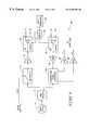
- FIG. 1is a block diagram illustrating a communication system embodying the invention.
- FIG. 2is a front view of an employee badge according to one embodiment the invention.
- FIG. 3is a front view of a radio frequency identification tag according to another embodiment of the invention.
- FIG. 4is a circuit schematic of a transponder included in the system of FIG. 1 .
- FIG. 5is a block diagram of an interrogator in accordance with one embodiment of the invention.
- FIG. 6is a circuit schematic of DPSK circuitry included in the interrogator of FIG. 5 .
- FIG. 7is a circuit schematic of RF circuitry included in the interrogator of FIG. 5 .
- FIG. 8illustrates a stack or queue containing data representing an order of antennas to use in attempts to communicate from the interrogator to the transponder of FIG. 2 or 3 .
- FIG. 9illustrates the stack after being rearranged in accordance with one embodiment of the invention.
- FIG. 10illustrates the stack after being rearranged in accordance with another embodiment of the invention.
- FIG. 11is a circuit schematic of RF circuitry included in an interrogator in accordance with an alternative embodiment of the invention.
- FIG. 12illustrates pointers pointing to rows in a look-up table containing data representing an order of antennas to use in attempts to communicate from the interrogator of FIG. 11 to the transponder of FIG. 2 or 3 .
- FIG. 13illustrates the rows to which the pointers point being changed in accordance with one embodiment of the invention.
- FIG. 14illustrates the rows to which the pointers point being changed in accordance with another embodiment of the invention.
- the inventionprovides a wireless communications system comprising a first transponder adapted to be coupled to one of a plurality of selectable antennas, having a look-up table including locations holding data representing antennas, and having pointers pointing to the locations.
- the pointersdefine an order in which antennas will be used to attempt communication.
- the communications systemfurther includes a second transponder configured to communicate with the first transponder.
- the first transponderuses an antenna defined by data in one location of the look-up table for communication with the second transponder. If successful communication with the second transponder is not established, the transponder uses an antenna defined by data in another location of the look-up table.
- the first transpondercommunicates with the second transponder using backscatter communication. More particularly, in this embodiment, the first transponder employs separate receive and transmit antennas, and wherein the respective locations of the look-up table store data representing antenna pairs including one transmit antenna and one receive antenna.
- the second transpondercomprises an integrated circuit including a transmitter, a receiver, and a microprocessor.
- the second transpondercomprises a radio frequency identification device including memory storing data identifying the second transponder.
- a queue or stackincluding locations holding data representing antennas.
- the queue or stackdefines an order in which antennas will be used to attempt communication. If successful communication with the second transponder is not established, the transponder uses an antenna defined by data in another location of the queue or stack.
- FIG. 1illustrates a wireless communications system 10 embodying the invention.
- the communications system 10includes a first transponder including an interrogator unit (interrogator) 26 and a host computer 48 in communication with the interrogator 26 .
- the communications system 10further includes a radio frequency data communication device 12 such as the device disclosed in commonly assigned U.S. Patent application Ser. No. 08/705,043, filed Aug. 29, 1996, and incorporated herein by reference. While other embodiments are possible, in the illustrated embodiment, the radio frequency data communications device 12 includes a transponder 16 having a receiver 30 and a transmitter 32 .
- the data communications device 12further includes a power source 18 connected to the transponder 16 to supply power to the transponder 16 .
- the data communications device 12further includes at least one antenna connected to the transponder 16 for wireless transmission and reception.
- the data communications device 12includes at least one antenna 46 connected to the transponder 16 for radio frequency transmission by the transponder 16 , and at least one receive antenna 44 connected to the transponder 16 for radio frequency reception by the transponder 16 .
- the device 12includes a single antenna for transmitting and receiving.
- the transponder 16is in the form of an integrated circuit. However, in alternative embodiments, some or all of the circuitry of the transponder 16 is not necessarily all included in a single integrated circuit.
- the power source 18is a thin film battery in the illustrated embodiment; however, in alternative embodiments, other forms of power sources can be employed.
- the radio frequency data communication device 12can be included in any appropriate housing or packaging.
- FIG. 2shows but one example of a housing in the form of a card 11 comprising plastic or other suitable material.
- the plastic card 11houses the radio frequency data communication device 12 to define an employee identification badge 13 including the radio frequency data communication device 12 .
- the front face of the badge 13has visual identification features including an employee photograph as well as identifying text.
- FIG. 3illustrates but one alternative housing supporting the device 12 . More particularly, FIG. 3 illustrates a miniature housing 20 encasing the device 12 to defame a tag which can be supported by an object (e.g., hung from an object, affixed to an object, etc.).
- an objecte.g., hung from an object, affixed to an object, etc.
- the device 12can be included in any appropriate housing.
- the device 12is of a small size that lends itself to applications employing small housings, such as cards, miniature tags, etc. Larger housings can also be employed.
- the device 12housed in any appropriate housing, can be supported from or attached to an object in any desired manner.
- the housingcan be sewn on to an object, hung from an object, implanted in an object (hidden), etc.
- the antenna connected to the transponder 16may be Various configurations.
- separate antennas 44 and 46are provided for receiver and transmitter.
- a single antennais shared by the receiver and transmitter.
- one or more antennasare defined by conductive epoxy screened onto a card or housing. In the illustrated embodiment, the antenna is conductively bonded to the integrated circuit via bonding pads.
- the batterycan take any suitable form.
- the battery typewill be selected depending on weight, size, and life requirements for a particular application.
- the battery 18is a thin profile button-type cell forming a small, thin energy cell more commonly utilized in watches and small electronic devices requiring a thin profile.
- a conventional button-type cellhas a pair of electrodes, an anode formed by one face and a cathode formed by an opposite face.
- the battery 18comprises a series connected pair of button type cells.
- any suitable power sourcecan be employed.
- the device 12transmits and receives radio frequency communications to and from the interrogator 26 .
- the interrogator 26includes a plurality of antennas, as well as transmitting and receiving circuitry, similar to that implemented in the device 16 .
- the host computer 48acts as a master in a master-slave relationship with the interrogator 26 .
- the host computer 48includes an applications program for controlling the interrogator 26 and interpreting responses, and a library of radio frequency identification device applications or functions. Most of the functions communicate with the interrogator 26 . These functions effect radio frequency communication between the interrogator 26 and the device 12 . These functions are described below in a section titled “Protocol.”
- the host computer 48 and the interrogator 26are combined together (e.g., in a common housing), or functions of the host computer are implemented in hard wired digital logic circuitry.
- the communications system 10includes multiple selectable transmit antennas Xl, X 2 , etc., and multiple receive antennas R 1 , R 2 , etc. connected to the interrogator 26 .
- the communications system 10includes multiple selectable antennas that are respectively used both for transmitting and receiving by the interrogator 26 .
- the interrogator 26transmits an interrogation signal or command 27 (“forward link”) via one of the antennas Xl, X 2 , etc.
- the device 12receives the incoming interrogation signal via its antenna 44 .
- the device 12responds by generating and transmitting a responsive signal or reply 29 (“return link”).
- the interrogator 26is described below in greater detail.
- the responsive signal 29is encoded with information that uniquely identifies, or labels the particular device 12 that is transmitting, so as to identify any object or person with which the device 12 is associated.
- informationthat uniquely identifies, or labels the particular device 12 that is transmitting, so as to identify any object or person with which the device 12 is associated.
- Other embodimentsare possible for the device 12 , such as cellular telephone embodiments, or embodiments that include global positioning circuitry (e.g., such as the transponder devices sold by Micron Communications, Inc. under the trademark “AMBIT.”
- multiple devices 12can be employed; however, there is no communication between multiple devices 12 . Instead, the multiple devices 12 communicate with the interrogator 26 .
- FIG. 1illustrates the device 12 as being in the housing 20 of FIG. 3 .
- the systemwould operate in a similar manner if the device 12 is provided in a housing such as the housing 10 of FIG. 2, or any other appropriate housing.
- Multiple devices 12can be used in the same field of an interrogator 26 (i.e., within communications range of an interrogator 26 ). Similarly, multiple interrogators 26 can be in proximity to one or more of the devices 12 .
- the system 10is advantageous over prior art devices that utilize magnetic field effect systems because, with the system 10 , a greater range can be achieved, and more information can be obtained (instead of just an identification number). As a result, such a system 10 can be used, for many applications.
- the system 10is useful whenever transmission over a large range is desirable, such as for inventory control.
- the sensitivity of the devices 12is adjustable so that only devices within a certain range of the interrogator 26 will respond.
- the power of the interrogator 26is adjustable so that only devices within a certain range of the interrogator 26 will respond.
- FIG. 4is a high level circuit schematic of the transponder 16 utilized in the devices of FIGS. 1-3.
- the transponder 16is a monolithic integrated circuit. More particularly, in the illustrated embodiment, the integrated circuit 16 comprises a single die, having a size of 209 ⁇ 116 mils 2 , including the receiver 30 , the transmitter 32 , a micro controller or microprocessor 34 , a wake up timer and logic circuit 36 , a clock recovery and data recovery circuit 38 , and a bias voltage and current generator 42 .
- the devices 12switch between a “sleep” mode of operation, and higher power modes to conserve energy and extend battery life during periods of time where no interrogation signal 27 is received by the device 12 , using wake up timer and logic circuitry 36 .
- a spread spectrum processing circuit 40is also included in the transponder 16 .
- signals transmitted and received by the interrogator 26 , and transmitted and received by the device 12are modulated spread spectrum signals.
- Spread spectrum modulationis described below.
- the modulation scheme for replies sent by the transmitter 32is selectable.
- One of the available selections for replies sent by the transmitter 32is modulated spread spectrum.
- the spread spectrum modulation technique employed in the illustrated embodimentrequires a transmission bandwidth that is up to several orders of magnitude greater than the minimum required signal bandwidth.
- spread spectrum modulation techniquesare bandwidth inefficient in single user applications, they are advantageous where there are multiple users, as is the case with the instant radio frequency identification system 24 .
- the spread spectrum modulation technique of the illustrated embodimentis advantageous because the interrogator signal can be distinguished from other signals (e.g., radar, microwave ovens, etc.) operating at the same frequency.
- the spread spectrum signals transmitted by the device 12 and by the interrogator 26are pseudo random and have noise-like properties when compared with the digital command or reply.
- the spreading waveformis controlled by a pseudo-noise or pseudo random number (PN) sequence or code.
- the PN codeis a binary sequence that appears random but can be reproduced in a predetermined manner by the device 12 . More particularly, incoming spread spectrum signals are demodulated by the device 12 or by the interrogator 26 through cross correlation with a version of the pseudo random carrier that is generated by the device 12 itself or the interrogator 26 itself, respectfully. Cross correlation with the correct PN sequence unspreads the spread spectrum signal and restores the modulated message in the same narrow band as the original data.
- a pseudo-noise or pseudo random sequenceis a binary sequence with an autocorrelation that resembles, over a period, the autocorrelation of a random binary sequence.
- the autocorrelation of a pseudo-noise sequencealso roughly resembles the autocorrelation of band-limited white noise.
- a pseudo-noise sequencehas many characteristics that are similar to those of random binary sequences. For example, a pseudo-noise sequence has a nearly equal number of zeros and ones, very low correlation between shifted versions of the sequence, and very low cross correlation between any two sequences.
- a pseudo-noise sequenceis usually generated using sequential logic circuits. For example, a pseudo-noise sequence can be generated using a feedback shift register.
- a feedback shift registercomprises consecutive stages of two state memory devices, and feedback logic. Binary sequences are shifted through the shift registers in response to clock pulses, and the output of the various stages are logically combined and fed back as the input to the first stage. The initial contents of the memory stages and the feedback logic circuit determine the successive contents of the memory.
- the illustrated embodimentemploys direct sequence spread spectrum modulation.
- a direct sequence spread spectrum (DSSS) systemspreads the baseband data by directly multiplying the baseband data pulses with a pseudo-noise sequence that is produced by a pseudo-noise generator.
- a single pulse or symbol of the PN waveformis called a “chip.”
- Synchronized data symbolswhich may be information bits or binary channel code symbols, are added in modulo-2 fashion to the chips before being modulated.
- the receiverperforms demodulation.
- the datais phase modulated, and the receiver performs coherent or differentially coherent phase-shift keying (PSK) demodulation.
- PSKphase-shift keying
- the datais amplitude modulated. Assuming that code synchronization has been achieved at the receiver, the received signal passes through a wideband filter and is multiplied by a local replica of the PN code sequence. This multiplication yields the unspread signal.
- a pseudo-noise sequenceis usually an odd number of chips long.
- one bit of datais represented by a thirty-one chip sequence.
- a zero bit of datais represented by inverting the pseudo-noise sequence.
- the interrogatorsends out a command that is spread around a certain center frequency (e.g, 2.44 GHz). After the interrogator transmits the command, and is expecting a response, the interrogator switches to a CW mode (continuous wave mode). In the continuous wave mode, the interrogator does not transmit any information. Instead, the interrogator just transmits 2.44 GHz radiation. In other words, the signal transmitted by the interrogator is not modulated.
- the device 12receives the command from the interrogator, the device 12 processes the command. If the device 12 is in a backscatter mode it alternately reflects or does not reflect the signal from the interrogator to send its reply. For example, in the illustrated embodiment, two halves of a dipole antenna are either shorted together or isolated from each other to send a reply.
- Frequency hoppingis employed in one embodiment.
- frequency hoppingdoes not occur when the interrogator transmits a command, but occurs when the interrogator is in the continuous wave mode.
- the interrogatorin the continuous wave mode, hops between various frequencies close to the 2.44 GHz frequency. These various frequencies are sufficiently close to the 2.44 GHz frequency that backscatter antenna reflection characteristics of the device 12 are not appreciably altered. Because the interrogator is hopping between frequencies, the interrogator knows what frequency backscatter reflections to expect back from the device 12 . By hopping between various frequencies, the amount of time the interrogator continuously uses a single frequency is reduced. This is advantageous in view of FCC regulatory requirements.
- the transmitter 32is switchable between operating in a modulated backscatter transmitter mode, and operating in an active mode.
- the transmitter 32switches between the backscatter mode and the active mode in response to a radio frequency command, instructing the transmitter to switch, sent by the interrogator 26 and received by the receiver 30 .
- a carrier for the transmitteris extracted from a signal received by the receiver 30 .
- the transmitter 32is capable of transmitting using different modulation schemes, and the modulation scheme is selectable by the interrogator. More particularly, if it is desired to change the modulation scheme, the interrogator sends an appropriate command via radio frequency.
- the transmittercan switch between multiple available modulation schemes such as Binary Phase Shift Keying (BPSK), Direct Sequence Spread Spectrum, On-Off Keying (OOK), and Modulated Backscatter (MBS).
- BPSKBinary Phase Shift Keying
- OOKOn-Off Keying
- MFSModulated Backscatter
- the clock for the entire integrated circuit 16is extracted from the incoming message itself by clock recovery and data recovery circuitry 38 .
- This clockis recovered from the incoming message, and used for timing for the micro controller 34 and all the other clock circuitry on the chip, and also for deriving the transmitter carrier or the subcarrier, depending on whether the transmitter is operating in active mode or backscatter mode.
- the clock recovery and data recovery circuit 38In addition to recovering a clock, the clock recovery and data recovery circuit 38 also performs data recovery on valid incoming signals.
- the valid spread spectrum incoming signalis passed through the spread spectrum processing circuit 40 , and the spread spectrum processing circuit 40 extracts the actual ones and zeros of data from the incoming signal. More particularly, the spread spectrum processing circuit 40 takes the chips from the spread spectrum signal, and reduces each thirty-one chip section down to a bit of one or zero, which is passed to the micro controller 34 .
- the micro controller 34includes a serial processor, or I/O facility that received the bits from the spread spectrum processing circuit 40 .
- the micro controller 34performs further error correction. More particularly, a modified hamming code is employed, where each eight bits of data is accompanied by five check bits used by the micro controller 34 for error correction.
- the micro controller 34further includes a memory, and after performing the data correction, the micro controller 34 stores bytes of the data bits in memory. These bytes contain a command sent by the interrogator 26 . The micro controller 34 responds to the command.
- the interrogator 26may send a command requesting that any device 12 in the field respond with the device's identification number. Status information is also returned to the interrogator 26 from the device 12 when the device 12 responds.
- the transmitted replieshave a format similar to the format of incoming messages. More particularly, a reply starts with a preamble (e.g., all zeros in active mode, or alternating double zeros and double ones in backscatter mode), followed by a Barker or start code which is thirteen bits long, followed by actual data.
- a preamblee.g., all zeros in active mode, or alternating double zeros and double ones in backscatter mode
- Barker or start codewhich is thirteen bits long, followed by actual data.
- No stop bitsare included in the incoming message or reply, in the preferred embodiment. Instead, part of the incoming message describes how many bytes are included, so the integrated circuit 16 knows how much information is included. Similarly, part of the outgoing reply describes how many bytes are included, so the interrogator 12 knows how much information is included.
- the incoming message and outgoing replypreferably also include a check sum or redundancy code so that the integrated circuit 16 or the interrogator 12 can confirm receipt of the entire message or reply.
- the integrated circuit 16After the reply is sent, the integrated circuit 16 returns to the sleep mode, and the wake up timer and logic circuit 36 starts timing again for the next wake up (e.g., in 16 milliseconds, or whatever period is selected).
- the interrogator 26provides a communication link between a host computer and the transponder 16 .
- the interrogator 26connects to the host computer 48 via an IEEE-1284 enhanced parallel port (EPP).
- EPPenhanced parallel port
- the interrogatorcommunicates with the transponder 16 via the RF antennas X 1 , X 2 , . . . , R 1 , R 2 . . . , etc.
- communications from the interrogator 26 to the transponder 16 , and communications from the transponder 16 to the interrogator 26use different physical protocols.
- the physical communications protocol for communications from the interrogator 26 to the transponder 16is referred to as the “forward link” protocol.
- the forward link datais sent in the following order:
- PN Sequenceis used in the Direct Sequence Spread Spectrum (DSSS) communications scheme in the forward link.
- the sequenceis generated by a linear feedback shift register .of the form [5.2]. That is, there are five registers, the output of the second register is X-ORed with the output of the fifth register, and the result is fed into the input of the first register one. This produces a repeating 31 “chip” sequence. The sequence ends with all registers set to one. The sequence is taken from the output of the first register. This code is synchronous with the data in that each data bit comprises one and only one full PN sequence.
- the chip sequence for each bitis:
- a zero bitis transmitted as one inverted full cycle of the PN sequence.
- a one bitis transmitted as one full non-inverted cycle of the PN sequence.
- the datais not differentially encoded.
- One rateis 9.5375 Mchips/sec (high band) and another rate is 4.768750 Mchips/sec (low band).
- the preambleprecedes the data.
- the preambleincludes a series of zeros, followed by a start or Barker code.
- the preambleincludes a series of zeros for a duration equal to the wakeup interval (e.g., 0.5, 16, 64, or 256 ms) plus 2 milliseconds, followed by a start or Barker code.
- the Barker codeis defined by the following bit string: 1111 1001 1010 1. Other embodiments are possible.
- Command datais grouped into 13-bit words.
- Each wordincludes eight data bits (D 7 , D 6 , D 5 , D 4 , D 3 , D 2 , D 1 , DO) and five ECC (Error Correction Code) bits (P 4 , P 3 , P 2 , P 1 , and P 0 ).
- the bit transmission orderis (with D 7 transmitted first): D 7 , D 6 , D 5 , D 4 , D 3 , D 2 , D 1 , DO, P 4 , P 3 , P 2 , P 1 , P 0 . . .
- the ECC bits (P 4 -P 0 )are generated using the following equations:
- the high data bandhas an effective data rate (adjusting for PN and ECC) of 189.3 Kbps.
- the low data bandhas an effective data rate of 94.68 Kbps.
- a 16-bit check sumis provided to detect bit errors on the packet level.
- a transponder 16can be programmed to either return a reply if a bad check sum is found in the forward link, or to simply halt execution and send no replies.
- a 16 bit CRCis employed in the forward link, the return link, or both, instead of or in addition to the check sum.
- the physical communications protocol for communications from the transponder 16 to the interrogator 26is referred to as the “return link” protocol.
- the return link messagesare sent in the following order:
- the interrogatorAfter sending a command, the interrogator sends a continuous unmodulated RF signal with a frequency of 2.44; GHz.
- Return link datais Differential Phase Shift Key (DPSK) modulated onto a square wave subcarrier with a frequency of 596.1 KHz.
- a data 0corresponds to one phase and data 1 corresponds to another, shifted 180 degrees from the first phase.
- the subcarrieris used to modulate antenna impedance of a transponder 16 .
- a switch between the two halves of the dipole antennais opened and closed. When the switch is closed, the antenna becomes the electrical equivalent of a single half-wavelength antenna that reflects a portion of the power being transmitted by the interrogator.
- the antennaWhen the switch is open, the antenna becomes the electrical equivalent of two quarter-wavelength antennas that reflect very little of the power transmitted by the interrogator.
- the switch driving a printed half wavelength dipole antennagives a typical range of 15 feet when the interrogator 26 transmits at 30 dBm into a 6 dB gain antenna.
- the preamble for the return linkincludes 2000 bits, alternating 2 zeros then 2 ones, etc., and a 13-bit start (Barker) code. Alternative preambles are possible.
- the start code or Barker Codeis defined by the following bit string: 1111 1001 1010 1.
- the reply link datais grouped in 13 bit words. Each word is composed of 8 data bits (D 7 , D 6 , DS, D 4 , D 3 , D 2 , D 1 , DO) and 5 ECC bits (P 4 , P 3 , P 2 , P 1 , P 0 ).
- the Block Encoded Sequenceis D 7 , D 6 , D 5 , D 4 , D 3 , D 2 , D 1 , DO, P 4 , P 3 , P 2 , P 1 , P 0 .
- P 4(DO+D 1 +D 2 +D 3 +D 4 +D 5 ) modulo 2.
- the bit durationis 6.71 ⁇ s making the effective data rate 91.75 Kbps for the return link.
- a 16 bit check sumis provided to detect bit errors on the packet level.
- a 16 bit CRCis employed in addition to or instead of the check sum.
- Each pair of data wordsis interleaved, starting with the Barker code and the first data word.
- the transmitted bit order for two sequential words, A and Bis D 7 A, D 7 B, D 6 A, D 6 B, D 5 A, D 5 B, D 4 A, D 4 B, D 3 A, D 3 B, D 2 A, D 2 B, D 1 A, D 1 B, D 0 A, D 0 B, P 4 A, P 4 B, P 3 A, P 3 B, P 2 A, P 2 B, P 1 A, P 1 B, P 0 A, P 0 B.
- D 7 Ais the first transmitted bit.
- DPSKis applied to the interleaved data.
- the interrogator 26includes enhanced parallel port (EPP) circuitry 50 , DPSK (differential phase shift keyed) circuitry 52 , and RF (radio frequency) circuitry 54 , as well as a power supply (not shown) and a housing or chassis (not shown).
- EPPenhanced parallel port
- DPSKdifferential phase shift keyed
- RFradio frequency
- the enhanced parallel port circuitry 50 , the DPSK circuitry 52 , and the RF circuitry 54respectively define circuit card assemblies (CCAs).
- the interrogatoruses an IEEE-1284 compatible port in EPP mode to communicate with the host computer 48 .
- the EPP circuitry 50provides all the digital logic required to coordinate sending and receiving a message with a transponder 16 .
- the EPP circuitry 50buffers data to transmit from the host computer 48 , converts the data to serial data, and encodes it. The EPP circuitry 50 then waits for data from the transponder 16 , converts it to parallel, and transfers it to the host computer 48 .
- messagesinclude up to 64 bytes of data.
- the EPP mode interfaceprovides an a synchronous, interlocked, byte wide, bidirectional channel controlled by a host device.
- the EPP modeallows the host computer to transfer, at high speed, a data byte to/from the interrogator within a single host computer CPU I/O cycle (typically 0.5 microseconds per byte).
- the DPSK circuitry 52receives signals I and Q from the RF circuitry 54 (described below), which signals contain the DPSK modulated sub-carrier.
- the DPSK circuitry 52includes anti-aliasing filters 56 and 58 filtering the I and Q signals, respectively, and analog to digital (AID) converters 60 and 62 respectively coupled to the filters 56 and 58 and respectively converting the filtered signals from analog to digital signals.
- the DPSK circuitry 52further includes a combiner 64 , coupled to the AID converters 60 and 62 , combining the digital signals.
- the DPSK circuitry 52further includes a FIR matched filter 66 , coupled to the combiner 64 , which filters the combined signals.
- the DPSK circuitry 52further includes delay circuitry 68 and multiplier circuitry 70 coupled to the FIR matched filter 66 for delaying the signal and multiplying the signal with the delayed signal to remove the sub-carrier.
- the DPSK circuitry 52further includes low pass filter circuitry 72 , coupled to the multiplier 70 , filtering the output of the multiplier 70 to remove the X 2 component.
- the DPSK circuitry 52further includes a bit synchronizer 74 coupled to the filter 72 for regeneration of the data clock.
- the DPSK circuitry 52further includes lock detect circuitry 76 coupled to the low pass filter 72 and generating a lock detect signal. The data, clock, and lock detect signal are sent to the EPP circuitry 50 .
- the RF circuitry 54(see FIG. 7) interfaces with the transmit and receive antennas X 1 , X 2 , R 1 , and R 2 .
- the RF circuitrymodulates the data for transmission to a transponder 16 , provides a continuous wave (CW) carrier for backscatter communications with a transponder 16 (if backscatter communications are employed), and receives and downconverts the signal received from the transponder unit (which is a backscatter signal in one embodiment).
- CWcontinuous wave
- the RF circuitry 54also includes a power divider 73 , and a frequency synthesizer 75 coupled to the power divider 73 .
- the frequency synthesizer 75tunes the RF continuous waver carrier for frequency hopping and band selection.
- the RF circuitrydefines a transmitter, and receives data from the EPP circuitry 50 .
- the RF circuitry 54includes an amplitude modulation (AM) switch 77 that receives the data from the EPP circuitry 50 and amplitude modulates the data onto a carrier. More particularly, the AM switch 77 turns the RF on and off (ON OFF KEY).
- the RF circuitry 54further includes a power amplifier 79 , coupled to the AM switch 77 , which amplifies the signal.
- AMamplitude modulation
- the RF circuitry 54further includes a diversity switch 78 , coupled to the power amplifier 79 , for transmission of the amplified signal through a selected one of the two transmit antennas X 1 and X 2 .
- the switch 78is coupled to more than two antennas and provides for switching from among the multiple antennas.
- the AM switch 77is left in a closed position.
- the transponder 16backscatters the signal with a DPSK modulated sub-carrier. This signal is received via one of the two diversity receive antennas R 1 and R 2 .
- the RF circuitry 54further includes a diversity switch 80 coupled to the receive antennas R 1 and R 2 .
- the switch 80is coupled to more than two receive antennas and provides for switching from among the multiple antennas.
- the RF circuitryuses common antennas for both transmission and reception, and selects from multiple available send/receive antennas.
- the RF circuitry 54further includes a low noise amplifier (LNA) 82 coupled to the switch 80 and amplifying the received signal.
- the RF circuitry 54further includes a quadrature downconverter 84 , coupled to the LNA 82 , coherently downconverting the received signal.
- the RF circuitry 54further includes automatic gain controls (AGCS) 86 and 88 coupled to the quadrature down converter 84 . The amplitude of the signals are set using the automatic gain controls 86 and 88 to provide the signals I and Q.
- the I and Q signalswhich contain the DPSK modulated sub-carrier, are passed on to the DPSK circuitry 52 for demodulation.
- FIG. 8illustrates a stack or queue 90 including locations holding data representing antennas X 1 , X 2 , R 1 , and R 2 .
- the stack or queue 90is defined by memory, such as random access memory included in the host computer 48 .
- the stack or queue 90defines an order in which antennas will be used to attempt communication. More particularly, in the illustrated embodiment, the stack 90 has a plurality of rows defining the locations. In the illustrated embodiment, the stack has two columns, one holding data representing a transmit antenna X 1 or X 2 , and another column holding data representing a receive antenna R 1 or R 2 , and the various rows represent various possible combinations of transmit and receive antennas that can be employed to attempt communications with a transponder 16 . In other embodiments, there are more than two send antennas and or receive antennas, so there will be more rows.
- antennasare used for both transmitting and receiving, and the stack includes only one column. Note that, although multiple columns are illustrated to aid in understanding, only two data bits of a single data word are required to hold information corresponding to one of the illustrated rows. Also, rows and columns can be swapped, as will be readily apparent. For example, FIG. 8 could be illustrated as two rows of four columns each.
- the transmit antennais preferably spaced apart from the transmit antenna X 1 .
- the receive antenna R 2is preferably spaced apart from the receive antenna R 1 .
- the transmit antenna X 1is spaced apart from the transmit antenna X 2 by a distance of one wavelength or more. Wavelength is calculated as the speed of light divided by the communications frequency; i.e., approximately 3.0 ⁇ 10 8 meters/second divided by 2.44 GHz.
- the transmit antenna X 1is spaced apart from the transmit antenna X 2 by a distance of between one wavelength and ten wavelengths.
- the receive antenna R 1is spaced apart from the receive antenna R 2 by a distance of one wavelength or more.
- the receive antenna R 1is spaced apart from the receive antenna R 2 by a distance of between one wavelength and ten wavelengths.
- the transmit antenna X 2is oriented at an angle different from the angle of the transmit antenna X 1 .
- the receive antenna R 2is oriented at an angle different from the angle of the receive antenna R 1 .
- the transmit antenna X 2is positioned at a height different from the height of the transmit antenna X 1 , relative to the ground.
- the receive antenna R 2is positioned at a height different from the height of the receive antenna R 1 , relative to the ground.
- the interrogatorWhen the interrogator attempts communication with a transponder 16 , the interrogator will first attempt communications using the data at the top of the queue 90 ; i.e., in the embodiment shown in FIG. 8, the interrogator will first attempt to use an antenna pair represented by data in the first or top row of the stack 90 (e.g., using transmit antenna X 1 and receive antenna R 1 in the illustrated embodiment). If successful communication is not established, the interrogator 26 will attempt communication using the antenna pair represented by data in the second row of the stack 90 (e.g., using transmit antenna X 1 and receive antenna receive antenna R 2 ).
- the interrogatorwill attempt communication using the antenna pair represented by data in the third row of the stack 90 (e.g., using transmit antenna X 2 and receive antenna receive antenna R 1 ). If successful communication is not established, the interrogator will attempt communication using the antenna pair represented by data in the fourth row of the stack (e.g., using transmit antenna X 2 and receive antenna receive antenna R 2 ). If successful communication is still not established, the interrogator may again attempt communication using the antenna pair represented by data in the first row of the stack, or may terminate attempts at communication (either for a predetermined amount of time, or indefinitely). Any initial ordering of the stack can, of course, be employed. Preferably, all possible combinations of transmit and receive antennas will be included in the stack; however, in other embodiments, not all combinations of transmit and receive antennas will be included in the stack.
- a problem with the method described in connection with FIG. 8is that if one of the antennas (X 1 , for example) is blocked, broken, jammed, etc., the communication attempt may fail using multiple rows (e.g., the communication attempt will fail both Attempt 1 and Attempt 2 shown in FIG. 8 if X 1 is blocked, etc.).
- Each attempttakes time. For example, in one embodiment, each attempt takes 20-40 milliseconds. Thus, in the illustrated embodiment, attempt 1 and attempt 2 fail, so 40-80 milliseconds are lost, even though a command will eventually be successfully sent from the interrogator to the transponder 16 .
- a “last-good-on-top” selectioncan be made, using the host computer 48 , in which the data representing the antenna pair for the last successful attempt is moved to the top of the stack; e.g., by a data arranger 92 included in the first transponder. Therefore, for the example described above, if successful communication does not take place until the antenna pair X 2 , R 1 is employed, data representing the antenna pair X 2 , R 1 is moved to the top of the stack 90 and the other pairs are pushed down as illustrated in FIG. 9 . Therefore, for the next command, the antenna pair X 2 , R 1 will be employed for the first communication attempt.
- the data arrangerre-orders the stack 90 as other hits occur (e.g., if the antenna pair represented by data in the top of the stack does not produce a successful communication but another antenna pair does produce a successful communication).
- a failed communicationmay be due to a temporary condition (e.g., caused by a moving object proximate a transponder 16 , by temporary interference, by temporary atmospheric conditions, etc.). Therefore, a “bubble-to-top” selection can be made, using the host computer 48 , in which the data representing the antenna pair for the last successful attempt is moved up in the queue 90 by only one slot (or row, or location) by the data arranger 92 . Therefore, for the example described above, if successful communication does not take place until the antenna pair X 2 , R 1 is employed, data representing the antenna pair X 2 , R 1 is swapped with data in the row above.
- data representing the antenna pair X 2 , R 1is moved up one row in the queue 90 and the data that was in that row is moved down one row.
- the resulting queue orderwill be that shown in FIG. 10 . Therefore, for the next command, the antenna pair X 1 , R 1 will still be employed for the first communication attempt.
- the data arranger 92is selectively instructed to employ “bubble-to-top” (e.g., FIG. 10) data rearrangement of the queue 90 , to employ “last-good-on-top” (e.g., FIG. 9) data rearrangement of the queue 90 , or to perform no rearrangement of the queue 90 (e.g., FIG. 8 ).
- This selectioncan be made, in one embodiment, using two data bits in a command sent from the host computer 48 to the interrogator 26 .
- no attemptis made to provide a separate stack or queue 90 for each transponder 16 ; however, in an alternative embodiment, a separate stack or queue 90 is maintained for each transponder 16 .
- FIG. 11is a circuit schematic of RF circuitry included in an interrogator in accordance with an alternative embodiment of the invention.
- FIG. 11shows RF circuitry 154 that is similar to the RF circuitry 54 of FIG. 7, like reference numerals indicating like components, except that the RF circuitry 154 includes a look-up table 94 and pointer array 96 coupled to the TX diversity switch 78 and RX diversity switch 80 .
- the look-up table 94is defined in memory, such as in random access memory or read only memory. More particularly, in the illustrated embodiment, the host computer 48 includes random access memory 98 defining the look-up table 94 and the pointer array 96 .
- Radio frequency signalsoccurs through a transmit antenna selected from a plurality of available antennas (e.g., X 1 , X 2 ) depending on data stored in the look-up table 94 and the pointer array 96 , as will be described below in greater detail.
- reception of radio frequency signalsoccurs though a receive antenna selected from a plurality of available antennas (e.g., R 1 , R 2 ) depending on data stored in the look-up table 94 and the pointer array 96 .
- the switch 78 of the RF circuitry 154is coupled to more than two antennas and provides for switching from among the multiple antennas
- the switch 80 of the RF circuitry 154is coupled to more than two antennas and provides for switching from among the multiple antennas.
- FIG. 12shows the pointer array 96 pointing to rows in the look-up table 94 .
- the pointer array 96is defined by a plurality of pointers or pointer array elements 0 , 1 , 2 , and 3 .
- the pointersare separate pointers as opposed to elements of an array.
- the element 0is the top element of the array 96
- the element 3is the bottom element of the array 96 .
- the array 96defines an order, from the top of the array to the bottom of the array, in which antennas will be used by the interrogator 26 to attempt communication.
- the table 94includes locations holding data representing antennas X 1 , X 2 , R 1 , and R 2 .
- the table 94has a plurality of rows 100 , 102 , 104 , and 106 , and two columns 108 and 110 .
- the column 108holds data representing a transmit antenna X 1 or X 2
- the column 110holds data representing a receive antenna R 1 or R 2
- the various rows 100 , 102 , 104 , and 106represent various possible combinations of transmit and receive antennas that can be employed to attempt communications with a transponder 16 .
- antennasare used for both transmitting and receiving, and the stack includes only one column. Note that, although multiple columns are illustrated to aid in understanding, only two data bits of a single data word are required to hold information corresponding to one of the illustrated rows. Also, rows and columns can be swapped, as will be readily apparent.
- the transmit antenna X 2is preferably spaced apart from the transmit antenna X 1
- the receive antenna R 2is preferably spaced apart from the receive antenna R 1 by previously described distances.
- the interrogator 26when the interrogator 26 attempts communication with a transponder 16 , the interrogator 26 will first attempt communications using an antenna pair represented by data in a row pointed to by the top or highest element 0 of the array 96 .
- the array element 0points to the first or top row 100 of the table 94 , so the switches 78 and 80 will switch to use transmit antenna X 1 and receive antenna R 1 .
- the interrogator 26will attempt communication using the antenna pair represented by data in the row of the table 94 pointed to by the next highest element 1 of the array 96 (e.g., using transmit antenna X 1 and receive antenna receive antenna R 2 ).
- the interrogatorwill attempt communication using the antenna pair represented by data in the row of the table 94 pointed to by the next highest element 2 of the array 96 (e.g., using transmit antenna X 2 and receive antenna receive antenna R 1 ). If successful communication is not established, the interrogator will attempt communication using the antenna pair represented by data pointed to by the next highest element 3 in the array 96 (e.g., using transmit antenna X 2 and receive antenna receive antenna R 2 ). If successful communication is still not established, the interrogator may again attempt communication using the antenna pair represented by data in the row pointed to by the first pointer element 0 , or may terminate attempts at communication (either for a predetermined amount of time, or indefinitely).
- any initial ordering of the table 94can, of course, be employed.
- the pointerscan initially point to any of the rows of the table 94 ; however, it is of course preferable that different pointers point to different rows.
- the number of pointers (array elements)is equal to the number of rows of the table 94 .
- all possible combinations of transmit and receive antennaswill be represented by data in the table 94 ; however, in other embodiments, not all combinations of transmit and receive antennas will be included.
- FIG. 13illustrates using a “last-good-on-top” selection in the embodiments employing pointers.
- the location values stored in the pointer array 96are re-arranged as other hits occur (e.g., if the antenna pair represented by data in the table pointed to by the top pointer 0 does not produce a successful communication but another antenna pair does produce a successful communication for a command).
- a “bubble-to-top” selectioncan also be made for the embodiment of FIGS. 11-12, using the host computer 48 , in which the location value of data representing the antenna pair for the last successful attempt is moved up in the pointer array 96 by only one slot to the next higher array element. Therefore, for the example shown in FIG. 12, if successful communication does not take place until the antenna pair X 2 , R 1 is employed, the location value in the third array element 2 is swapped with the location value in the next higher array element 1 as illustrated in FIG. 14 .
- data representing the antenna pair X 2 , R 1is pointed to by the pointer I
- data representing the antenna pair X 1 , R 2is pointed to by the pointer 2 .
- a usercan select the “best-on-top” mode of operation shown in FIG. 13, the “bubble-to-top” mode of FIG. 14, or a mode in which no rearrangement of the pointer array takes place after a successful communication.
- no attemptis made to provide a separate pointer array and table combination for each transponder 16 ; however, in an alternative embodiment, a pointer array and table is maintained for multiple transponders 16 with which the interrogator may communicate.
Landscapes
- Engineering & Computer Science (AREA)
- Computer Networks & Wireless Communication (AREA)
- General Physics & Mathematics (AREA)
- Signal Processing (AREA)
- Theoretical Computer Science (AREA)
- Physics & Mathematics (AREA)
- Computer Hardware Design (AREA)
- Microelectronics & Electronic Packaging (AREA)
- Artificial Intelligence (AREA)
- Computer Vision & Pattern Recognition (AREA)
- Mobile Radio Communication Systems (AREA)
- Near-Field Transmission Systems (AREA)
- Radio Transmission System (AREA)
- Transceivers (AREA)
Abstract
Description
Claims (12)
Priority Applications (11)
| Application Number | Priority Date | Filing Date | Title |
|---|---|---|---|
| US08/907,689US6289209B1 (en) | 1996-12-18 | 1997-08-08 | Wireless communication system, radio frequency communications system, wireless communications method, radio frequency communications method |
| DE69710221TDE69710221T2 (en) | 1996-12-18 | 1997-12-16 | WIRELESS COMMUNICATION SYSTEM AND METHOD WITH SEVERAL SELECTABLE ANTENNAS |
| EP97952452AEP0950288B1 (en) | 1996-12-18 | 1997-12-16 | Wireless communication system including a plurality of selectable antennas and wireless communications methods |
| AT97952452TATE212770T1 (en) | 1996-12-18 | 1997-12-16 | WIRELESS COMMUNICATIONS SYSTEM AND METHOD USING MULTIPLE SELECTABLE ANTENNAS |
| PCT/US1997/023105WO1998027670A1 (en) | 1996-12-18 | 1997-12-16 | Wireless communication system including a plurality of selectable antennas and wireless communications methods |
| JP52789298AJP3437971B2 (en) | 1996-12-18 | 1997-12-16 | A wireless communication system including a plurality of selectable antennas and a wireless communication method |
| AU56050/98AAU5605098A (en) | 1996-12-18 | 1997-12-16 | Wireless communication system including a plurality of selectable antennas and wireless communications methods |
| AU86915/98AAU8691598A (en) | 1997-08-08 | 1998-08-04 | Wireless communication system including a plurality of selectable antennas and wireless communications method |
| PCT/US1998/016283WO1999008402A1 (en) | 1997-08-08 | 1998-08-04 | Wireless communication system including a plurality of selectable antennas and wireless communications method |
| US09/843,115US6351630B2 (en) | 1996-12-18 | 2001-04-24 | Wireless communication system, radio frequency communications system, wireless communications method, radio frequency communications method, and backscatter radio frequency communications system |
| US10/020,801US6466771B2 (en) | 1996-12-18 | 2001-12-07 | Wireless communication system, radio frequency communications system, wireless communications method, radio frequency communications method, and backscatter radio frequency communications system |
Applications Claiming Priority (2)
| Application Number | Priority Date | Filing Date | Title |
|---|---|---|---|
| US08/772,173US5842118A (en) | 1996-12-18 | 1996-12-18 | Communication system including diversity antenna queuing |
| US08/907,689US6289209B1 (en) | 1996-12-18 | 1997-08-08 | Wireless communication system, radio frequency communications system, wireless communications method, radio frequency communications method |
Related Parent Applications (1)
| Application Number | Title | Priority Date | Filing Date |
|---|---|---|---|
| US08/772,173Continuation-In-PartUS5842118A (en) | 1996-12-18 | 1996-12-18 | Communication system including diversity antenna queuing |
Related Child Applications (1)
| Application Number | Title | Priority Date | Filing Date |
|---|---|---|---|
| US09/843,115ContinuationUS6351630B2 (en) | 1996-12-18 | 2001-04-24 | Wireless communication system, radio frequency communications system, wireless communications method, radio frequency communications method, and backscatter radio frequency communications system |
Publications (1)
| Publication Number | Publication Date |
|---|---|
| US6289209B1true US6289209B1 (en) | 2001-09-11 |
Family
ID=27118565
Family Applications (3)
| Application Number | Title | Priority Date | Filing Date |
|---|---|---|---|
| US08/907,689Expired - LifetimeUS6289209B1 (en) | 1996-12-18 | 1997-08-08 | Wireless communication system, radio frequency communications system, wireless communications method, radio frequency communications method |
| US09/843,115Expired - LifetimeUS6351630B2 (en) | 1996-12-18 | 2001-04-24 | Wireless communication system, radio frequency communications system, wireless communications method, radio frequency communications method, and backscatter radio frequency communications system |
| US10/020,801Expired - LifetimeUS6466771B2 (en) | 1996-12-18 | 2001-12-07 | Wireless communication system, radio frequency communications system, wireless communications method, radio frequency communications method, and backscatter radio frequency communications system |
Family Applications After (2)
| Application Number | Title | Priority Date | Filing Date |
|---|---|---|---|
| US09/843,115Expired - LifetimeUS6351630B2 (en) | 1996-12-18 | 2001-04-24 | Wireless communication system, radio frequency communications system, wireless communications method, radio frequency communications method, and backscatter radio frequency communications system |
| US10/020,801Expired - LifetimeUS6466771B2 (en) | 1996-12-18 | 2001-12-07 | Wireless communication system, radio frequency communications system, wireless communications method, radio frequency communications method, and backscatter radio frequency communications system |
Country Status (7)
| Country | Link |
|---|---|
| US (3) | US6289209B1 (en) |
| EP (1) | EP0950288B1 (en) |
| JP (1) | JP3437971B2 (en) |
| AT (1) | ATE212770T1 (en) |
| AU (1) | AU5605098A (en) |
| DE (1) | DE69710221T2 (en) |
| WO (1) | WO1998027670A1 (en) |
Cited By (56)
| Publication number | Priority date | Publication date | Assignee | Title |
|---|---|---|---|---|
| US20010014090A1 (en)* | 1998-02-19 | 2001-08-16 | Wood Clifton W. | Method of addressing messages and communications system |
| US20020090958A1 (en)* | 1999-03-09 | 2002-07-11 | Ovard David K. | Wireless communication systems, interrogators and methods of communication within a wireless communication system |
| US6452496B1 (en) | 1999-07-29 | 2002-09-17 | Micron Technology, Inc. | Radio frequency identification devices and a method of determining a communication range |
| US6459376B2 (en) | 1999-07-29 | 2002-10-01 | Micron Technology, Inc. | Radio frequency identification devices, remote communication devices, wireless communication systems, and methods of indicating operation |
| US20020141374A1 (en)* | 1999-11-30 | 2002-10-03 | Ulrich Boetzel | Method for controlling antennas of a receiving device in a radio system |
| US6509836B1 (en)* | 2000-03-31 | 2003-01-21 | Georgia Tech Research Corporation | Smart reflection antenna system and method |
| US6546245B1 (en)* | 1999-10-05 | 2003-04-08 | Agere Systems Inc. | Inverted code sequence cordless signaling |
| US20030100284A1 (en)* | 2001-11-27 | 2003-05-29 | Siemens Vdo Automotive | Process and device for isotropic communication between a vehicle and a tag |
| US6590498B2 (en)* | 1999-10-19 | 2003-07-08 | Lucent Technologies Inc. | Method and apparatus for improving the interrogation range of an RF-Tag |
| US6650695B1 (en)* | 1999-08-03 | 2003-11-18 | Intel Corporation | Wireless digital data transmission from a passive transceiver |
| US6686829B1 (en)* | 1998-01-19 | 2004-02-03 | Zih Corp. | Electronic identification system with forward error correction system |
| US20040046644A1 (en)* | 2002-09-05 | 2004-03-11 | Honeywell International Inc. | Efficient protocol for reading RFID tags |
| US20050078007A1 (en)* | 1999-02-10 | 2005-04-14 | Scott Hahn | Communications system and method with A/D converter |
| US20050083201A1 (en)* | 1999-07-29 | 2005-04-21 | Trosper Scott T. | Radio frequency identification devices, remote communication devices, identification systems, communication methods, and identification methods |
| US20050206552A1 (en)* | 2004-03-17 | 2005-09-22 | Ulrich Friedrich | Method for data transmission in RFID or remote sensor systems |
| EP1659516A1 (en)* | 2004-11-19 | 2006-05-24 | ATMEL Germany GmbH | Data transfer apparatus and data transfer method |
| US20060267735A1 (en)* | 1999-03-09 | 2006-11-30 | Ovard David K | Wireless communication systems, interrogators and methods of communicating within a wireless communication system |
| US20060279407A1 (en)* | 1999-03-09 | 2006-12-14 | Roy Greeff | Phase shifters, interrogators, methods of shifting a phase angle of a signal, and methods of operating an interrogator |
| US7296739B1 (en)* | 2000-03-31 | 2007-11-20 | Intel Corporation | Managing on-line transactions |
| US20080111675A1 (en)* | 2006-11-10 | 2008-05-15 | Micron Technology, Inc. | Tracking systems, passive RFIDs, methods of locating and identifying RFIDs, and methods of tracking items |
| US20080180221A1 (en)* | 2007-01-30 | 2008-07-31 | Micron Technology, Inc. | Systems and methods for RFID tag arbitration |
| US20080186178A1 (en)* | 2007-02-07 | 2008-08-07 | Micron Technology, Inc. | RFIDS, interrogators, indication systems, methods of determining a bi-directional communication range of an interrogator, methods of activating an observable indicator, and methods of indicating bi-directional functionality of a radio connection |
| US20080297324A1 (en)* | 2007-05-30 | 2008-12-04 | Micron Technology, Inc. | Methods and systems of receiving data payload of rfid tags |
| USRE40686E1 (en) | 1998-02-19 | 2009-03-31 | Keystone Technology Solutions, Llc | Method of addressing messages and communications system |
| US20090195361A1 (en)* | 2008-01-30 | 2009-08-06 | Smith Mark H | Array Antenna System and Algorithm Applicable to RFID Readers |
| US20090315683A1 (en)* | 2008-06-24 | 2009-12-24 | Keystone Technology Solutions, Llc | Analog RFID System |
| USRE41531E1 (en) | 1998-02-19 | 2010-08-17 | Round Rock Research, Llc | Communications systems for radio frequency identification (RFID) |
| USRE42344E1 (en) | 1998-02-19 | 2011-05-10 | Round Rock Research, Llc | Method and apparatus to manage RFID tags |
| US7959769B2 (en) | 2004-12-08 | 2011-06-14 | Infinite Power Solutions, Inc. | Deposition of LiCoO2 |
| US7993773B2 (en) | 2002-08-09 | 2011-08-09 | Infinite Power Solutions, Inc. | Electrochemical apparatus with barrier layer protected substrate |
| US8021778B2 (en) | 2002-08-09 | 2011-09-20 | Infinite Power Solutions, Inc. | Electrochemical apparatus with barrier layer protected substrate |
| USRE42751E1 (en) | 1998-09-03 | 2011-09-27 | Round Rock Research, Llc | Communication system, interrogators and communication methods |
| US8062708B2 (en) | 2006-09-29 | 2011-11-22 | Infinite Power Solutions, Inc. | Masking of and material constraint for depositing battery layers on flexible substrates |
| US8115635B2 (en) | 2005-02-08 | 2012-02-14 | Abbott Diabetes Care Inc. | RF tag on test strips, test strip vials and boxes |
| USRE43382E1 (en) | 1998-02-19 | 2012-05-15 | Round Rock Research, Llc | Method of addressing messages and communications systems |
| US20120139761A1 (en)* | 2009-06-05 | 2012-06-07 | Continental Teves Ag & Co. Ohg | Method for positioning and vehicle communication unit |
| US8197781B2 (en) | 2006-11-07 | 2012-06-12 | Infinite Power Solutions, Inc. | Sputtering target of Li3PO4 and method for producing same |
| US8236443B2 (en) | 2002-08-09 | 2012-08-07 | Infinite Power Solutions, Inc. | Metal film encapsulation |
| US8260203B2 (en) | 2008-09-12 | 2012-09-04 | Infinite Power Solutions, Inc. | Energy device with integral conductive surface for data communication via electromagnetic energy and method thereof |
| US8268488B2 (en) | 2007-12-21 | 2012-09-18 | Infinite Power Solutions, Inc. | Thin film electrolyte for thin film batteries |
| US8350519B2 (en) | 2008-04-02 | 2013-01-08 | Infinite Power Solutions, Inc | Passive over/under voltage control and protection for energy storage devices associated with energy harvesting |
| US8394522B2 (en) | 2002-08-09 | 2013-03-12 | Infinite Power Solutions, Inc. | Robust metal film encapsulation |
| US8404376B2 (en) | 2002-08-09 | 2013-03-26 | Infinite Power Solutions, Inc. | Metal film encapsulation |
| US8431264B2 (en) | 2002-08-09 | 2013-04-30 | Infinite Power Solutions, Inc. | Hybrid thin-film battery |
| US8445130B2 (en) | 2002-08-09 | 2013-05-21 | Infinite Power Solutions, Inc. | Hybrid thin-film battery |
| EP2624175A1 (en)* | 2012-02-06 | 2013-08-07 | François Domine | System and method for automatically locating objects removably positioned in predefined locations, using active RFID tags |
| US8508193B2 (en) | 2008-10-08 | 2013-08-13 | Infinite Power Solutions, Inc. | Environmentally-powered wireless sensor module |
| US8518581B2 (en) | 2008-01-11 | 2013-08-27 | Inifinite Power Solutions, Inc. | Thin film encapsulation for thin film batteries and other devices |
| US8599572B2 (en) | 2009-09-01 | 2013-12-03 | Infinite Power Solutions, Inc. | Printed circuit board with integrated thin film battery |
| US8636876B2 (en) | 2004-12-08 | 2014-01-28 | R. Ernest Demaray | Deposition of LiCoO2 |
| US8728285B2 (en) | 2003-05-23 | 2014-05-20 | Demaray, Llc | Transparent conductive oxides |
| US8855169B2 (en) | 1998-04-24 | 2014-10-07 | Round Rock Research, Llc | Methods and apparatus for RFID tag communications |
| US8906523B2 (en) | 2008-08-11 | 2014-12-09 | Infinite Power Solutions, Inc. | Energy device with integral collector surface for electromagnetic energy harvesting and method thereof |
| US9334557B2 (en) | 2007-12-21 | 2016-05-10 | Sapurast Research Llc | Method for sputter targets for electrolyte films |
| US9634296B2 (en) | 2002-08-09 | 2017-04-25 | Sapurast Research Llc | Thin film battery on an integrated circuit or circuit board and method thereof |
| US10680277B2 (en) | 2010-06-07 | 2020-06-09 | Sapurast Research Llc | Rechargeable, high-density electrochemical device |
Families Citing this family (76)
| Publication number | Priority date | Publication date | Assignee | Title |
|---|---|---|---|---|
| US5842118A (en)* | 1996-12-18 | 1998-11-24 | Micron Communications, Inc. | Communication system including diversity antenna queuing |
| US6289209B1 (en) | 1996-12-18 | 2001-09-11 | Micron Technology, Inc. | Wireless communication system, radio frequency communications system, wireless communications method, radio frequency communications method |
| WO1999008402A1 (en)* | 1997-08-08 | 1999-02-18 | Micron Communications, Inc. | Wireless communication system including a plurality of selectable antennas and wireless communications method |
| GB9813371D0 (en)* | 1998-06-22 | 1998-08-19 | Powell George L | Anti-collision tag apparatus and system |
| KR100699755B1 (en) | 1998-08-14 | 2007-03-27 | 쓰리엠 이노베이티브 프로퍼티즈 캄파니 | Radio Frequency Identification System Applications |
| EP1770592B1 (en) | 1998-08-14 | 2009-10-07 | 3M Innovative Properties Company | Method of interrogating a package bearing an RFID tag |
| JP2002522999A (en)* | 1998-08-14 | 2002-07-23 | スリーエム イノベイティブ プロパティズ カンパニー | Applications to radio frequency identification systems |
| US6577229B1 (en) | 1999-06-10 | 2003-06-10 | Cubic Corporation | Multiple protocol smart card communication device |
| US6944148B1 (en) | 1999-09-10 | 2005-09-13 | Pulse-Link, Inc. | Apparatus and method for managing variable-sized data slots within a time division multiple access frame |
| US7023833B1 (en) | 1999-09-10 | 2006-04-04 | Pulse-Link, Inc. | Baseband wireless network for isochronous communication |
| US7088795B1 (en) | 1999-11-03 | 2006-08-08 | Pulse-Link, Inc. | Ultra wide band base band receiver |
| US7970950B1 (en) | 2007-04-09 | 2011-06-28 | G&H Nevada—Tek | High-speed data transfer in a networked server environment via laser communication |
| US7219165B1 (en)* | 2000-01-14 | 2007-05-15 | G&H Nevada Tek | High-speed data transfer in a networked server environment via laser communication |
| DE60000039T2 (en)* | 2000-03-13 | 2002-07-11 | Datamars S.A., Bedano-Lugano | Method and device for reducing the influence of interference signals in applications with transponders |
| US6952456B1 (en)* | 2000-06-21 | 2005-10-04 | Pulse-Link, Inc. | Ultra wide band transmitter |
| US7397867B2 (en) | 2000-12-14 | 2008-07-08 | Pulse-Link, Inc. | Mapping radio-frequency spectrum in a communication system |
| US6816075B2 (en) | 2001-02-21 | 2004-11-09 | 3M Innovative Properties Company | Evidence and property tracking for law enforcement |
| US7035246B2 (en) | 2001-03-13 | 2006-04-25 | Pulse-Link, Inc. | Maintaining a global time reference among a group of networked devices |
| US20020180588A1 (en) | 2001-06-05 | 2002-12-05 | Erickson David P. | Radio frequency identification in document management |
| US7588185B2 (en) | 2001-06-07 | 2009-09-15 | 3M Innovative Properties Company | RFID data collection and use |
| JP3941620B2 (en)* | 2001-08-31 | 2007-07-04 | 株式会社デンソーウェーブ | Electronic device with built-in ID tag |
| US6894615B2 (en) | 2001-10-09 | 2005-05-17 | 3M Innovative Properties Company | Article with retroreflective and radio frequency-responsive features |
| US6758405B2 (en) | 2001-12-19 | 2004-07-06 | 3M Innovative Properties Company | Article with retroreflective and radio frequency-responsive features |
| US7697946B2 (en)* | 2002-06-04 | 2010-04-13 | Forster Ian J | Reflective communication using radio-frequency devices |
| EP1777642A1 (en) | 2002-06-04 | 2007-04-25 | Mineral Lassen LLC | Transmission of information using backscatter radio-frequency transponders |
| US7920827B2 (en) | 2002-06-26 | 2011-04-05 | Nokia Corporation | Apparatus and method for facilitating physical browsing on wireless devices using radio frequency identification |
| US7212788B2 (en)* | 2002-08-13 | 2007-05-01 | Atheros Communications, Inc. | Method and apparatus for signal power loss reduction in RF communication systems |
| US8532588B1 (en) | 2002-08-13 | 2013-09-10 | The Connectivity Patent Trust | Apparatus for signal power loss reduction in RF communication systems |
| US7044387B2 (en)* | 2002-09-05 | 2006-05-16 | Honeywell International Inc. | RFID tag and communication protocol for long range tag communications and power efficiency |
| US20040046642A1 (en)* | 2002-09-05 | 2004-03-11 | Honeywell International Inc. | Protocol for addressing groups of RFID tags |
| US6726099B2 (en) | 2002-09-05 | 2004-04-27 | Honeywell International Inc. | RFID tag having multiple transceivers |
| US7573370B2 (en)* | 2002-09-05 | 2009-08-11 | Honeywell International Inc. | Method and device for storing and distributing information in an RFID tag |
| US7171223B2 (en)* | 2003-01-10 | 2007-01-30 | Belair Networks, Inc. | Automatic antenna selection for mesh backhaul network nodes |
| US7236549B2 (en) | 2003-07-03 | 2007-06-26 | Freesystems Pte. Ltd | Digital switching wireless receiver diversity and buffer diversity for enhanced reception in a wireless digital audio communication system |
| US20050058292A1 (en)* | 2003-09-11 | 2005-03-17 | Impinj, Inc., A Delaware Corporation | Secure two-way RFID communications |
| US7218214B2 (en)* | 2003-10-27 | 2007-05-15 | David R. Werner | Auxiliary safety light system |
| CN101189623B (en)* | 2003-10-29 | 2010-06-02 | Nxp股份有限公司 | Communication partner appliance with automatic send mode activation and method therefor |
| US20060108421A1 (en)* | 2003-12-03 | 2006-05-25 | Becker Robert C | RFID tag having multiple transceivers |
| JP2005217621A (en)* | 2004-01-28 | 2005-08-11 | Kyocera Corp | Mobile communication terminal and communication system |
| CN1918585B (en) | 2004-03-19 | 2010-05-05 | 诺基亚公司 | Detector logic and radio identification device and method for enhanced terminal operation |
| US20050237161A1 (en)* | 2004-04-23 | 2005-10-27 | Microchip Technology Incorporated | Programmable selective wake-up for radio frequency transponder |
| GB0411193D0 (en)* | 2004-05-20 | 2004-06-23 | Koninkl Philips Electronics Nv | Method and apparatus for determining distance to a radio transponder |
| US7299042B2 (en) | 2004-07-30 | 2007-11-20 | Pulse-Link, Inc. | Common signaling method and apparatus |
| JP4229057B2 (en)* | 2004-12-09 | 2009-02-25 | セイコーエプソン株式会社 | POSITIONING SIGNAL RECEIVING DEVICE AND POSITIONING SIGNAL RECEIVING DEVICE CONTROL METHOD |
| US7295120B2 (en) | 2004-12-10 | 2007-11-13 | 3M Innovative Properties Company | Device for verifying a location of a radio-frequency identification (RFID) tag on an item |
| KR101075651B1 (en)* | 2005-02-07 | 2011-10-21 | 삼성전자주식회사 | Privacy protection rfid tag and method for protecting privacy information |
| US7515051B2 (en)* | 2005-02-25 | 2009-04-07 | Datalogic Mobile, Inc. | RFID antenna system having reduced orientation sensitivity |
| KR100791025B1 (en)* | 2005-12-31 | 2008-01-03 | 주식회사 유컴테크놀러지 | Air Channel Access Method and Tag Zone Partitioning Method in Mobile RF ID System |
| EP1809053A1 (en)* | 2006-01-12 | 2007-07-18 | Siemens Aktiengesellschaft | Arrangement for combining the output signals from two base stations |
| FR2901077B1 (en)* | 2006-05-10 | 2008-07-11 | Inside Contactless Sa | METHOD FOR ROUTING INPUT AND OUTGOING DATA IN AN NFC CHIP SET |
| EP1855229B1 (en)* | 2006-05-10 | 2010-08-11 | Inside Contactless | Method of routing input and output data in an NFC chipset |
| FR2901076B1 (en)* | 2006-05-10 | 2008-07-11 | Inside Contactless Sa | METHOD FOR ROUTING OUTGOING AND INPUT DATA IN AN NFC CHIPSET |
| US7664527B2 (en)* | 2006-08-04 | 2010-02-16 | At&T Mobility Ii Llc | Network identity and timezone (NITZ) functionality for non-3GPP devices |
| US8570172B2 (en)* | 2006-09-08 | 2013-10-29 | Intelleflex Corporation | RFID system with distributed transmitters |
| WO2008053789A1 (en)* | 2006-10-31 | 2008-05-08 | Semiconductor Energy Laboratory Co., Ltd. | Semiconductor device |
| GB2445974B (en) | 2007-01-25 | 2011-05-11 | Hewlett Packard Development Co | Apparatus for and method of selecting between antennas for wireless communication |
| JP4985237B2 (en)* | 2007-08-29 | 2012-07-25 | 株式会社デンソーウェーブ | RF tag system, RF tag and tag reader |
| JP4985239B2 (en)* | 2007-08-30 | 2012-07-25 | 株式会社デンソーウェーブ | RF tag system, RF tag and tag reader |
| JP4285576B1 (en)* | 2007-12-04 | 2009-06-24 | オムロン株式会社 | Non-contact IC medium communication apparatus and method, and program thereof |
| JP4353298B2 (en)* | 2007-12-13 | 2009-10-28 | オムロン株式会社 | Non-contact IC medium direction detection device and method, and program thereof |
| KR100968970B1 (en)* | 2007-12-29 | 2010-07-14 | 삼성전기주식회사 | Antenna diversity receiver |
| US20100060424A1 (en)* | 2008-03-19 | 2010-03-11 | Checkpoint Systems, Inc. | Range Extension and Multiple Access in Modulated Backscatter Systems |
| JP5203142B2 (en)* | 2008-11-04 | 2013-06-05 | 株式会社日立製作所 | Electronic circuit and wireless communication system |
| CN102362439B (en) | 2009-01-26 | 2015-06-10 | 德雷塞尔大学 | Systems and methods for selecting reconfigurable antennas in MIMO systems |
| WO2010135559A1 (en)* | 2009-05-20 | 2010-11-25 | Infinite Power Solutions, Inc. | Method of integrating electrochemical devices into and onto fixtures |
| US8477045B2 (en)* | 2009-10-29 | 2013-07-02 | Hewlett-Packard Development Company, L.P. | Configuration information provided to configurable electronic device residing in a shipping box |
| CN102148538B (en)* | 2010-02-05 | 2015-07-08 | 株式会社半导体能源研究所 | Mobile body, wireless power supply system, and wireless power supply method |
| RU2494258C2 (en)* | 2011-11-16 | 2013-09-27 | Федеральное государственное бюджетное образовательное учреждение высшего профессионального образования "Уральский государственный университет путей сообщения" (УрГУПС) | Device for sending messages to underground mine |
| DE102011055738B4 (en)* | 2011-11-25 | 2021-10-21 | Infineon Technologies Ag | Communication method between electronic devices and related devices |
| US20150257006A1 (en)* | 2014-03-05 | 2015-09-10 | Alcatel Lucent | Security mechanism for short range radio frequency communication |
| JP6464757B2 (en)* | 2015-01-15 | 2019-02-06 | オムロン株式会社 | system |
| US11506777B2 (en)* | 2018-03-24 | 2022-11-22 | Brandon Li | RFID tag location and association of RFID tags |
| EP3799358A1 (en)* | 2019-09-27 | 2021-03-31 | Tridonic GmbH & Co. KG | Bulk configuration of building technology devices |
| KR102743721B1 (en) | 2019-11-08 | 2024-12-17 | 삼성전자주식회사 | Method for selecting transmission antenna and electonic device |
| US11210480B2 (en)* | 2019-12-20 | 2021-12-28 | Zebra Technologies Corporation | Dynamic compensation of a phased array RFID reader |
| US11448722B2 (en)* | 2020-03-26 | 2022-09-20 | Intel Corporation | Apparatus, system and method of communicating radar signals |
Citations (26)
| Publication number | Priority date | Publication date | Assignee | Title |
|---|---|---|---|---|
| US4075632A (en) | 1974-08-27 | 1978-02-21 | The United States Of America As Represented By The United States Department Of Energy | Interrogation, and detection system |
| US4584709A (en) | 1983-07-06 | 1986-04-22 | Motorola, Inc. | Homotropic antenna system for portable radio |
| US4742567A (en) | 1985-02-01 | 1988-05-03 | Toyota Jidosha Kabushiki Kaisha | Automobile antenna system |
| US4926182A (en) | 1986-05-30 | 1990-05-15 | Sharp Kabushiki Kaisha | Microwave data transmission apparatus |
| EP0474491A2 (en) | 1990-09-06 | 1992-03-11 | NCR International, Inc. | Method and apparatus for processing a received wireless data signal |
| US5097484A (en) | 1988-10-12 | 1992-03-17 | Sumitomo Electric Industries, Ltd. | Diversity transmission and reception method and equipment |
| US5203024A (en) | 1990-04-27 | 1993-04-13 | Nippon Telegraph & Telephone Corp. | Antenna selection diversity reception system |
| US5203018A (en) | 1989-07-06 | 1993-04-13 | Oki Electric Industry Co., Ltd. | Space diversity system switching transmission |
| US5432027A (en) | 1994-03-02 | 1995-07-11 | Micron Communications, Inc. | Button-type battery having bendable construction, and angled button-type battery |
| EP0670558A2 (en) | 1994-03-04 | 1995-09-06 | AT&T Corp. | Modulated backscatter wireless communication system having an extended range |
| WO1995030290A1 (en) | 1994-04-28 | 1995-11-09 | Northern Telecom Limited | Method for transmitting messages in multipath propagation using space and time diversity |
| US5491723A (en) | 1993-05-06 | 1996-02-13 | Ncr Corporation | Wireless communication system having antenna diversity |
| US5494495A (en) | 1994-10-11 | 1996-02-27 | Micron Communications, Inc. | Method of forming button-type batteries |
| US5497140A (en) | 1992-08-12 | 1996-03-05 | Micron Technology, Inc. | Electrically powered postage stamp or mailing or shipping label operative with radio frequency (RF) communication |
| US5499397A (en) | 1994-05-02 | 1996-03-12 | Motorola, Inc. | Switched antenna diversity algorithm employing received signal strength, phase errors and recovered clock |
| US5507035A (en) | 1993-04-30 | 1996-04-09 | International Business Machines Corporation | Diversity transmission strategy in mobile/indoor cellula radio communications |
| US5539775A (en) | 1993-03-17 | 1996-07-23 | Micron Technology, Inc. | Modulated spread spectrum in RF identification systems method |
| US5568512A (en) | 1994-07-27 | 1996-10-22 | Micron Communications, Inc. | Communication system having transmitter frequency control |
| EP0740262A2 (en) | 1995-04-28 | 1996-10-30 | Texas Instruments Deutschland Gmbh | Identification system reader with multiplexed antennas |
| US5583850A (en) | 1992-12-15 | 1996-12-10 | Micron Technology, Inc. | Data communication system using identification protocol |
| US5613219A (en)* | 1993-02-05 | 1997-03-18 | U.S. Philips Corporation | Transceiver having plural antennas and adjusting the time delay of transmitted signals to match the time delay of received signals |
| US5621412A (en) | 1994-04-26 | 1997-04-15 | Texas Instruments Incorporated | Multi-stage transponder wake-up, method and structure |
| US5649296A (en) | 1995-06-19 | 1997-07-15 | Lucent Technologies Inc. | Full duplex modulated backscatter system |
| US5662718A (en) | 1994-12-01 | 1997-09-02 | Micron Communications, Inc. | Method of forming thin profile batteries and a thin profile battery insulating and sealing gasket |
| WO1998027670A1 (en) | 1996-12-18 | 1998-06-25 | Micron Communications, Inc. | Wireless communication system including a plurality of selectable antennas and wireless communications methods |
| US5842118A (en)* | 1996-12-18 | 1998-11-24 | Micron Communications, Inc. | Communication system including diversity antenna queuing |
Family Cites Families (1)
| Publication number | Priority date | Publication date | Assignee | Title |
|---|---|---|---|---|
| JP3250708B2 (en) | 1995-04-27 | 2002-01-28 | シャープ株式会社 | Wireless communication device |
- 1997
- 1997-08-08USUS08/907,689patent/US6289209B1/ennot_activeExpired - Lifetime
- 1997-12-16EPEP97952452Apatent/EP0950288B1/ennot_activeExpired - Lifetime
- 1997-12-16JPJP52789298Apatent/JP3437971B2/ennot_activeExpired - Fee Related
- 1997-12-16ATAT97952452Tpatent/ATE212770T1/ennot_activeIP Right Cessation
- 1997-12-16WOPCT/US1997/023105patent/WO1998027670A1/enactiveIP Right Grant
- 1997-12-16AUAU56050/98Apatent/AU5605098A/ennot_activeAbandoned
- 1997-12-16DEDE69710221Tpatent/DE69710221T2/ennot_activeExpired - Lifetime
- 2001
- 2001-04-24USUS09/843,115patent/US6351630B2/ennot_activeExpired - Lifetime
- 2001-12-07USUS10/020,801patent/US6466771B2/ennot_activeExpired - Lifetime
Patent Citations (26)
| Publication number | Priority date | Publication date | Assignee | Title |
|---|---|---|---|---|
| US4075632A (en) | 1974-08-27 | 1978-02-21 | The United States Of America As Represented By The United States Department Of Energy | Interrogation, and detection system |
| US4584709A (en) | 1983-07-06 | 1986-04-22 | Motorola, Inc. | Homotropic antenna system for portable radio |
| US4742567A (en) | 1985-02-01 | 1988-05-03 | Toyota Jidosha Kabushiki Kaisha | Automobile antenna system |
| US4926182A (en) | 1986-05-30 | 1990-05-15 | Sharp Kabushiki Kaisha | Microwave data transmission apparatus |
| US5097484A (en) | 1988-10-12 | 1992-03-17 | Sumitomo Electric Industries, Ltd. | Diversity transmission and reception method and equipment |
| US5203018A (en) | 1989-07-06 | 1993-04-13 | Oki Electric Industry Co., Ltd. | Space diversity system switching transmission |
| US5203024A (en) | 1990-04-27 | 1993-04-13 | Nippon Telegraph & Telephone Corp. | Antenna selection diversity reception system |
| EP0474491A2 (en) | 1990-09-06 | 1992-03-11 | NCR International, Inc. | Method and apparatus for processing a received wireless data signal |
| US5497140A (en) | 1992-08-12 | 1996-03-05 | Micron Technology, Inc. | Electrically powered postage stamp or mailing or shipping label operative with radio frequency (RF) communication |
| US5583850A (en) | 1992-12-15 | 1996-12-10 | Micron Technology, Inc. | Data communication system using identification protocol |
| US5613219A (en)* | 1993-02-05 | 1997-03-18 | U.S. Philips Corporation | Transceiver having plural antennas and adjusting the time delay of transmitted signals to match the time delay of received signals |
| US5539775A (en) | 1993-03-17 | 1996-07-23 | Micron Technology, Inc. | Modulated spread spectrum in RF identification systems method |
| US5507035A (en) | 1993-04-30 | 1996-04-09 | International Business Machines Corporation | Diversity transmission strategy in mobile/indoor cellula radio communications |
| US5491723A (en) | 1993-05-06 | 1996-02-13 | Ncr Corporation | Wireless communication system having antenna diversity |
| US5432027A (en) | 1994-03-02 | 1995-07-11 | Micron Communications, Inc. | Button-type battery having bendable construction, and angled button-type battery |
| EP0670558A2 (en) | 1994-03-04 | 1995-09-06 | AT&T Corp. | Modulated backscatter wireless communication system having an extended range |
| US5621412A (en) | 1994-04-26 | 1997-04-15 | Texas Instruments Incorporated | Multi-stage transponder wake-up, method and structure |
| WO1995030290A1 (en) | 1994-04-28 | 1995-11-09 | Northern Telecom Limited | Method for transmitting messages in multipath propagation using space and time diversity |
| US5499397A (en) | 1994-05-02 | 1996-03-12 | Motorola, Inc. | Switched antenna diversity algorithm employing received signal strength, phase errors and recovered clock |
| US5568512A (en) | 1994-07-27 | 1996-10-22 | Micron Communications, Inc. | Communication system having transmitter frequency control |
| US5494495A (en) | 1994-10-11 | 1996-02-27 | Micron Communications, Inc. | Method of forming button-type batteries |
| US5662718A (en) | 1994-12-01 | 1997-09-02 | Micron Communications, Inc. | Method of forming thin profile batteries and a thin profile battery insulating and sealing gasket |
| EP0740262A2 (en) | 1995-04-28 | 1996-10-30 | Texas Instruments Deutschland Gmbh | Identification system reader with multiplexed antennas |
| US5649296A (en) | 1995-06-19 | 1997-07-15 | Lucent Technologies Inc. | Full duplex modulated backscatter system |
| WO1998027670A1 (en) | 1996-12-18 | 1998-06-25 | Micron Communications, Inc. | Wireless communication system including a plurality of selectable antennas and wireless communications methods |
| US5842118A (en)* | 1996-12-18 | 1998-11-24 | Micron Communications, Inc. | Communication system including diversity antenna queuing |
Cited By (138)
| Publication number | Priority date | Publication date | Assignee | Title |
|---|---|---|---|---|
| US6686829B1 (en)* | 1998-01-19 | 2004-02-03 | Zih Corp. | Electronic identification system with forward error correction system |
| US7327218B2 (en) | 1998-01-19 | 2008-02-05 | Zih Corp. | Electronic identification system with forward error correction system |
| US20050237155A1 (en)* | 1998-01-19 | 2005-10-27 | Zih Corp., A Delaware Corporation | Electronic identification system with forward error correction system |
| US6958678B2 (en)* | 1998-01-19 | 2005-10-25 | Zih Corp. | Electronic identification system with forward error correction system |
| US20040090310A1 (en)* | 1998-01-19 | 2004-05-13 | Zih Corp. | Electronic identification system with forward error correction system |
| US20050207364A1 (en)* | 1998-02-19 | 2005-09-22 | Wood Clifton W Jr | Method of addressing messages and communications system |
| USRE43254E1 (en) | 1998-02-19 | 2012-03-20 | Round Rock Research, Llc | Method of addressing messages and communications systems |
| USRE42599E1 (en) | 1998-02-19 | 2011-08-09 | Round Rock Research, Llc | Method of addressing messages and communications system |
| US20080007412A1 (en)* | 1998-02-19 | 2008-01-10 | Wood Clifton W Jr | Method of Addressing Messages and Communications System |
| US8638709B2 (en) | 1998-02-19 | 2014-01-28 | Round Rock Research, Llc | Methods and apparatus for conducting financial transactions |
| USRE41531E1 (en) | 1998-02-19 | 2010-08-17 | Round Rock Research, Llc | Communications systems for radio frequency identification (RFID) |
| US8040829B2 (en) | 1998-02-19 | 2011-10-18 | Round Rock Research, Llc | Method of addressing messages and communications system |
| USRE42254E1 (en) | 1998-02-19 | 2011-03-29 | Round Rock Research, Llc | Method of addressing messages and communications system |
| US8634338B2 (en) | 1998-02-19 | 2014-01-21 | Round Rock Research, Llc | Methods and apparatus for conducting financial transactions |
| USRE41471E1 (en) | 1998-02-19 | 2010-08-03 | Round Rock Research, Llc | Method of Addressing Messages and Communications System |
| US20080042806A1 (en)* | 1998-02-19 | 2008-02-21 | Wood Clifton W Jr | Method of Addressing Messages and Communications System |
| US7315522B2 (en)* | 1998-02-19 | 2008-01-01 | Micron Technology, Inc. | Communication methods using slotted replies |
| US7760677B2 (en) | 1998-02-19 | 2010-07-20 | Keystone Technology Solutions, Llc | Method of addressing messages and communications system |
| USRE44411E1 (en) | 1998-02-19 | 2013-08-06 | Round Rock Research, Llc | Method of addressing messages, method of establishing wireless communications and communications system |
| USRE42900E1 (en) | 1998-02-19 | 2011-11-08 | Round Rock Research, Llc | Method of addressing messages and communications systems |
| USRE43445E1 (en) | 1998-02-19 | 2012-06-05 | Round Rock Research, Llc | Method and apparatus to manage RFID tags |
| US7936706B2 (en) | 1998-02-19 | 2011-05-03 | Round Rock Research, Llc | Method of addressing messages and communications system |
| USRE42344E1 (en) | 1998-02-19 | 2011-05-10 | Round Rock Research, Llc | Method and apparatus to manage RFID tags |
| US20060056325A1 (en)* | 1998-02-19 | 2006-03-16 | Wood Clifton W Jr | Method of addressing messages and communications system |
| USRE41352E1 (en) | 1998-02-19 | 2010-05-25 | Keystone Technology Solutions, Llc | Method of addressing messages and communications |
| US7672260B2 (en) | 1998-02-19 | 2010-03-02 | Keystone Technology Solutions, Llc | Method of addressing messages and communications system |
| US8488581B2 (en) | 1998-02-19 | 2013-07-16 | Round Rock Research, Llc | Methods and apparatus for conducting financial transactions |
| US20090322491A1 (en)* | 1998-02-19 | 2009-12-31 | Keystone Technology Solutions, Llc | Method of Addressing Messages and Communications System |
| US7639638B2 (en) | 1998-02-19 | 2009-12-29 | Keystone Technology Solutions, Llc | Method and apparatus for an arbitration scheme for radio frequency identification devices |
| US20060209781A1 (en)* | 1998-02-19 | 2006-09-21 | Micron Technology, Inc. | Method of addressing messages and communications system |
| USRE43020E1 (en) | 1998-02-19 | 2011-12-13 | Round Rock Research, Llc | Method of addressing messages, method of establishing wireless communications, and communications system |
| US20010014090A1 (en)* | 1998-02-19 | 2001-08-16 | Wood Clifton W. | Method of addressing messages and communications system |
| USRE40686E1 (en) | 1998-02-19 | 2009-03-31 | Keystone Technology Solutions, Llc | Method of addressing messages and communications system |
| US9014077B2 (en) | 1998-02-19 | 2015-04-21 | Round Rock Research, Llc | Methods and apparatus for conducting financial transactions |
| USRE43382E1 (en) | 1998-02-19 | 2012-05-15 | Round Rock Research, Llc | Method of addressing messages and communications systems |
| US8855169B2 (en) | 1998-04-24 | 2014-10-07 | Round Rock Research, Llc | Methods and apparatus for RFID tag communications |
| USRE43242E1 (en)* | 1998-09-03 | 2012-03-13 | Round Rock Research, Llc | Communication system, interrogators and communication methods |
| USRE42751E1 (en) | 1998-09-03 | 2011-09-27 | Round Rock Research, Llc | Communication system, interrogators and communication methods |
| US7327263B2 (en) | 1999-02-10 | 2008-02-05 | Micron Technology, Inc. | Communications system and method with A/D converter |
| US20080048866A1 (en)* | 1999-02-10 | 2008-02-28 | Scott Hahn | Communications System and Method with A/D Converter |
| US20050078007A1 (en)* | 1999-02-10 | 2005-04-14 | Scott Hahn | Communications system and method with A/D converter |
| US7994922B2 (en) | 1999-02-10 | 2011-08-09 | Round Rock Research, Llc | Communications system and method with A/D converter |
| US20070290813A1 (en)* | 1999-03-09 | 2007-12-20 | Ovard David K | Wireless Communication Systems, Interrogators and Methods of Communicating Within a Wireless Communication System |
| US20080001754A1 (en)* | 1999-03-09 | 2008-01-03 | Ovard David K | Wireless Communication Systems, Interrogators and Methods of Communicating Within a Wireless Communication System |
| US20070290806A1 (en)* | 1999-03-09 | 2007-12-20 | Roy Greeff | Phase Shifters, Interrogators, Methods Of Shifting A Phase Angle Of A Signal, And Methods Of Operating An Interrogator |
| US7982586B2 (en) | 1999-03-09 | 2011-07-19 | Round Rock Research, Llc | Wireless communication systems, interrogators and methods of communicating within a wireless communication system |
| US20020090958A1 (en)* | 1999-03-09 | 2002-07-11 | Ovard David K. | Wireless communication systems, interrogators and methods of communication within a wireless communication system |
| US8174361B2 (en) | 1999-03-09 | 2012-05-08 | Round Rock Research, Llc | Phase shifters, interrogators, methods of shifting a phase angle of a signal, and methods of operating an interrogator |
| US7898390B2 (en) | 1999-03-09 | 2011-03-01 | Round Rock Research, Llc | Phase shifters, interrogators, methods of shifting a phase angle of a signal, and methods of operating an interrogator |
| US20060279407A1 (en)* | 1999-03-09 | 2006-12-14 | Roy Greeff | Phase shifters, interrogators, methods of shifting a phase angle of a signal, and methods of operating an interrogator |
| US7969284B2 (en) | 1999-03-09 | 2011-06-28 | Round Rock Research, Llc | Wireless communication systems, interrogators and methods of communicating within a wireless communication system |
| US20060267735A1 (en)* | 1999-03-09 | 2006-11-30 | Ovard David K | Wireless communication systems, interrogators and methods of communicating within a wireless communication system |
| US7592898B1 (en) | 1999-03-09 | 2009-09-22 | Keystone Technology Solutions, Llc | Wireless communication systems, interrogators and methods of communicating within a wireless communication system |
| US8351968B2 (en) | 1999-03-09 | 2013-01-08 | Round Rock Research, Llc | Wireless communication systems, interrogators and methods of communication within a wireless communication system |
| US7737851B2 (en) | 1999-07-29 | 2010-06-15 | Round Rock Research, Llc | Radio frequency identification devices, remote communication devices, identification systems, communication methods, and identification methods |
| US7071824B2 (en) | 1999-07-29 | 2006-07-04 | Micron Technology, Inc. | Radio frequency identification devices, remote communication devices, identification systems, communication methods, and identification methods |
| US20100013637A1 (en)* | 1999-07-29 | 2010-01-21 | Keystone Technology Solutions, Llc | Radio Frequency Identification Devices, Remote Communication Devices, Identification Systems, Communication Methods, and Identification Methods |
| US7518515B2 (en) | 1999-07-29 | 2009-04-14 | Keystone Technology Solutions, Llc | Method and system for RFID communication |
| US7123148B2 (en) | 1999-07-29 | 2006-10-17 | Micron Technology, Inc. | Wireless communication devices, radio frequency identification devices, radio frequency identification device communication systems, wireless communication methods, and radio frequency identification device communication methods |
| US8487766B2 (en) | 1999-07-29 | 2013-07-16 | Round Rock Research, LLP | Radio frequency identification devices, remote communication devices, identification systems, communication methods, and identification methods |
| US20070035395A1 (en)* | 1999-07-29 | 2007-02-15 | Trosper Scott T | Wireless communication devices, radio frequency identification devices, radio frequency identification device communication systems, wireless communication methods, and radio frequency identification device communication methods |
| US20050083201A1 (en)* | 1999-07-29 | 2005-04-21 | Trosper Scott T. | Radio frequency identification devices, remote communication devices, identification systems, communication methods, and identification methods |
| US6459376B2 (en) | 1999-07-29 | 2002-10-01 | Micron Technology, Inc. | Radio frequency identification devices, remote communication devices, wireless communication systems, and methods of indicating operation |
| US8253565B2 (en) | 1999-07-29 | 2012-08-28 | Round Rock Research, Llc | Radio frequency identification devices, remote communication devices, identification systems, communication methods, and identification methods |
| US6452496B1 (en) | 1999-07-29 | 2002-09-17 | Micron Technology, Inc. | Radio frequency identification devices and a method of determining a communication range |
| US6466130B2 (en) | 1999-07-29 | 2002-10-15 | Micron Technology, Inc. | Wireless communication devices, wireless communication systems, communication methods, methods of forming radio frequency identification devices, methods of testing wireless communication operations, radio frequency identification devices, and methods of forming radio frequency identification devices |
| US8004407B2 (en) | 1999-07-29 | 2011-08-23 | Round Rock Research, Llc | Radio frequency identification devices, remote communication devices, identification systems, communication methods, and identification methods |
| US7035322B2 (en) | 1999-08-03 | 2006-04-25 | Intel Corporation | Wireless digital data transmission from a passive transceiver |
| US6650695B1 (en)* | 1999-08-03 | 2003-11-18 | Intel Corporation | Wireless digital data transmission from a passive transceiver |
| US20040087345A1 (en)* | 1999-08-03 | 2004-05-06 | Intel Corporation | Wireless digital data transmission from a passive transceiver |
| US6546245B1 (en)* | 1999-10-05 | 2003-04-08 | Agere Systems Inc. | Inverted code sequence cordless signaling |
| US6590498B2 (en)* | 1999-10-19 | 2003-07-08 | Lucent Technologies Inc. | Method and apparatus for improving the interrogation range of an RF-Tag |
| US20020141374A1 (en)* | 1999-11-30 | 2002-10-03 | Ulrich Boetzel | Method for controlling antennas of a receiving device in a radio system |
| US7039090B2 (en)* | 1999-11-30 | 2006-05-02 | Infineon Technologies Ag | Method for controlling antennas of a receiving device in a radio system |
| US7296739B1 (en)* | 2000-03-31 | 2007-11-20 | Intel Corporation | Managing on-line transactions |
| US6509836B1 (en)* | 2000-03-31 | 2003-01-21 | Georgia Tech Research Corporation | Smart reflection antenna system and method |
| US6934513B2 (en) | 2001-11-27 | 2005-08-23 | Siemens Vdo Automotive | Process and device for isotropic communication between a vehicle and a tag |
| US20030100284A1 (en)* | 2001-11-27 | 2003-05-29 | Siemens Vdo Automotive | Process and device for isotropic communication between a vehicle and a tag |
| FR2832881A1 (en)* | 2001-11-27 | 2003-05-30 | Siemens Vdo Automotive | Isotropic communication method in hands-free vehicle control system, involves deciding to process signals received from internal or external antenna, as function of compensated amplitudes |
| US7993773B2 (en) | 2002-08-09 | 2011-08-09 | Infinite Power Solutions, Inc. | Electrochemical apparatus with barrier layer protected substrate |
| US9634296B2 (en) | 2002-08-09 | 2017-04-25 | Sapurast Research Llc | Thin film battery on an integrated circuit or circuit board and method thereof |
| US9793523B2 (en) | 2002-08-09 | 2017-10-17 | Sapurast Research Llc | Electrochemical apparatus with barrier layer protected substrate |
| US8021778B2 (en) | 2002-08-09 | 2011-09-20 | Infinite Power Solutions, Inc. | Electrochemical apparatus with barrier layer protected substrate |
| US8535396B2 (en) | 2002-08-09 | 2013-09-17 | Infinite Power Solutions, Inc. | Electrochemical apparatus with barrier layer protected substrate |
| US8236443B2 (en) | 2002-08-09 | 2012-08-07 | Infinite Power Solutions, Inc. | Metal film encapsulation |
| US8445130B2 (en) | 2002-08-09 | 2013-05-21 | Infinite Power Solutions, Inc. | Hybrid thin-film battery |
| US8431264B2 (en) | 2002-08-09 | 2013-04-30 | Infinite Power Solutions, Inc. | Hybrid thin-film battery |
| US8404376B2 (en) | 2002-08-09 | 2013-03-26 | Infinite Power Solutions, Inc. | Metal film encapsulation |
| US8394522B2 (en) | 2002-08-09 | 2013-03-12 | Infinite Power Solutions, Inc. | Robust metal film encapsulation |
| US20040046644A1 (en)* | 2002-09-05 | 2004-03-11 | Honeywell International Inc. | Efficient protocol for reading RFID tags |
| US7239229B2 (en)* | 2002-09-05 | 2007-07-03 | Honeywell International Inc. | Efficient protocol for reading RFID tags |
| US8728285B2 (en) | 2003-05-23 | 2014-05-20 | Demaray, Llc | Transparent conductive oxides |
| US7733217B2 (en) | 2004-03-17 | 2010-06-08 | Atmel Automotive Gmbh | Method for data transmission in RFID or remote sensor systems |
| US20050206552A1 (en)* | 2004-03-17 | 2005-09-22 | Ulrich Friedrich | Method for data transmission in RFID or remote sensor systems |
| US7768948B2 (en) | 2004-11-19 | 2010-08-03 | Atmel Automotive Gmbh | Method and device for data transmission |
| EP1659516A1 (en)* | 2004-11-19 | 2006-05-24 | ATMEL Germany GmbH | Data transfer apparatus and data transfer method |
| US20060153123A1 (en)* | 2004-11-19 | 2006-07-13 | Atmel Germany Gmbh | Method and device for data transmission |
| US7959769B2 (en) | 2004-12-08 | 2011-06-14 | Infinite Power Solutions, Inc. | Deposition of LiCoO2 |
| US8636876B2 (en) | 2004-12-08 | 2014-01-28 | R. Ernest Demaray | Deposition of LiCoO2 |
| US8223021B2 (en) | 2005-02-08 | 2012-07-17 | Abbott Diabetes Care Inc. | RF tag on test strips, test strip vials and boxes |
| US8115635B2 (en) | 2005-02-08 | 2012-02-14 | Abbott Diabetes Care Inc. | RF tag on test strips, test strip vials and boxes |
| US8542122B2 (en) | 2005-02-08 | 2013-09-24 | Abbott Diabetes Care Inc. | Glucose measurement device and methods using RFID |
| US8358210B2 (en) | 2005-02-08 | 2013-01-22 | Abbott Diabetes Care Inc. | RF tag on test strips, test strip vials and boxes |
| US8390455B2 (en) | 2005-02-08 | 2013-03-05 | Abbott Diabetes Care Inc. | RF tag on test strips, test strip vials and boxes |
| US8062708B2 (en) | 2006-09-29 | 2011-11-22 | Infinite Power Solutions, Inc. | Masking of and material constraint for depositing battery layers on flexible substrates |
| US8197781B2 (en) | 2006-11-07 | 2012-06-12 | Infinite Power Solutions, Inc. | Sputtering target of Li3PO4 and method for producing same |
| US20080111675A1 (en)* | 2006-11-10 | 2008-05-15 | Micron Technology, Inc. | Tracking systems, passive RFIDs, methods of locating and identifying RFIDs, and methods of tracking items |
| US7855643B2 (en) | 2006-11-10 | 2010-12-21 | Round Rock Research, Llc | Tracking systems, passive RFIDs, methods of locating and identifying RFIDs, and methods of tracking items |
| US20110084808A1 (en)* | 2006-11-10 | 2011-04-14 | Round Rock Research, Llc | Tracking systems, methods of locating and identifying rfids, and methods of tracking items |
| US8207856B2 (en) | 2007-01-30 | 2012-06-26 | Round Rock Research, Llc | Systems and methods for RFID tag arbitration where RFID tags generate multiple random numbers for different arbitration sessions |
| US7973644B2 (en) | 2007-01-30 | 2011-07-05 | Round Rock Research, Llc | Systems and methods for RFID tag arbitration where RFID tags generate multiple random numbers for different arbitration sessions |
| US20080180221A1 (en)* | 2007-01-30 | 2008-07-31 | Micron Technology, Inc. | Systems and methods for RFID tag arbitration |
| US20080186178A1 (en)* | 2007-02-07 | 2008-08-07 | Micron Technology, Inc. | RFIDS, interrogators, indication systems, methods of determining a bi-directional communication range of an interrogator, methods of activating an observable indicator, and methods of indicating bi-directional functionality of a radio connection |
| US8134452B2 (en) | 2007-05-30 | 2012-03-13 | Round Rock Research, Llc | Methods and systems of receiving data payload of RFID tags |
| US20080297324A1 (en)* | 2007-05-30 | 2008-12-04 | Micron Technology, Inc. | Methods and systems of receiving data payload of rfid tags |
| US9334557B2 (en) | 2007-12-21 | 2016-05-10 | Sapurast Research Llc | Method for sputter targets for electrolyte films |
| US8268488B2 (en) | 2007-12-21 | 2012-09-18 | Infinite Power Solutions, Inc. | Thin film electrolyte for thin film batteries |
| US9786873B2 (en) | 2008-01-11 | 2017-10-10 | Sapurast Research Llc | Thin film encapsulation for thin film batteries and other devices |
| US8518581B2 (en) | 2008-01-11 | 2013-08-27 | Inifinite Power Solutions, Inc. | Thin film encapsulation for thin film batteries and other devices |
| US8593283B2 (en)* | 2008-01-30 | 2013-11-26 | Mark H. Smith | Array antenna system and algorithm applicable to RFID readers |
| US20170169261A1 (en)* | 2008-01-30 | 2017-06-15 | Mark H. Smith | Array antenna system and algorithm applicable to rfid readers |
| US8952815B2 (en)* | 2008-01-30 | 2015-02-10 | Mark H. Smith | Array antenna system and algorithm applicable to RFID readers |
| US20140076972A1 (en)* | 2008-01-30 | 2014-03-20 | Mark H. Smith | Array antenna system and algorithm applicable to rfid readers |
| US20090195361A1 (en)* | 2008-01-30 | 2009-08-06 | Smith Mark H | Array Antenna System and Algorithm Applicable to RFID Readers |
| US10445538B2 (en)* | 2008-01-30 | 2019-10-15 | Metrc Llc | Array antenna system and algorithm applicable to RFID readers |
| US20150154430A1 (en)* | 2008-01-30 | 2015-06-04 | Mark H. Smith | Array antenna system and algorithm applicable to rfid readers |
| KR20100134572A (en)* | 2008-01-30 | 2010-12-23 | 프란웰, 아이엔씨. | Array Antenna System and Algorithm Applicable to RFID Readers |
| US8350519B2 (en) | 2008-04-02 | 2013-01-08 | Infinite Power Solutions, Inc | Passive over/under voltage control and protection for energy storage devices associated with energy harvesting |
| US20090315683A1 (en)* | 2008-06-24 | 2009-12-24 | Keystone Technology Solutions, Llc | Analog RFID System |
| US8906523B2 (en) | 2008-08-11 | 2014-12-09 | Infinite Power Solutions, Inc. | Energy device with integral collector surface for electromagnetic energy harvesting and method thereof |
| US8260203B2 (en) | 2008-09-12 | 2012-09-04 | Infinite Power Solutions, Inc. | Energy device with integral conductive surface for data communication via electromagnetic energy and method thereof |
| US8508193B2 (en) | 2008-10-08 | 2013-08-13 | Infinite Power Solutions, Inc. | Environmentally-powered wireless sensor module |
| US8896467B2 (en)* | 2009-06-05 | 2014-11-25 | Continental Teves Ag & Co. Ohg | Method for positioning and vehicle communication unit |
| US20120139761A1 (en)* | 2009-06-05 | 2012-06-07 | Continental Teves Ag & Co. Ohg | Method for positioning and vehicle communication unit |
| US8599572B2 (en) | 2009-09-01 | 2013-12-03 | Infinite Power Solutions, Inc. | Printed circuit board with integrated thin film battery |
| US9532453B2 (en) | 2009-09-01 | 2016-12-27 | Sapurast Research Llc | Printed circuit board with integrated thin film battery |
| US10680277B2 (en) | 2010-06-07 | 2020-06-09 | Sapurast Research Llc | Rechargeable, high-density electrochemical device |
| EP2624175A1 (en)* | 2012-02-06 | 2013-08-07 | François Domine | System and method for automatically locating objects removably positioned in predefined locations, using active RFID tags |
Also Published As
| Publication number | Publication date |
|---|---|
| ATE212770T1 (en) | 2002-02-15 |
| US20020055345A1 (en) | 2002-05-09 |
| DE69710221D1 (en) | 2002-03-14 |
| US20010016479A1 (en) | 2001-08-23 |
| AU5605098A (en) | 1998-07-15 |
| JP2001500710A (en) | 2001-01-16 |
| WO1998027670A1 (en) | 1998-06-25 |
| US6351630B2 (en) | 2002-02-26 |
| EP0950288A1 (en) | 1999-10-20 |
| JP3437971B2 (en) | 2003-08-18 |
| US6466771B2 (en) | 2002-10-15 |
| DE69710221T2 (en) | 2002-09-19 |
| EP0950288B1 (en) | 2002-01-30 |
Similar Documents
| Publication | Publication Date | Title |
|---|---|---|
| US6289209B1 (en) | Wireless communication system, radio frequency communications system, wireless communications method, radio frequency communications method | |
| US5842118A (en) | Communication system including diversity antenna queuing | |
| US6169474B1 (en) | Method of communications in a backscatter system, interrogator, and backscatter communications system | |
| US6459726B1 (en) | Backscatter interrogators, communication systems and backscatter communication methods | |
| US6324211B1 (en) | Interrogators communication systems communication methods and methods of processing a communication signal | |
| USRE43242E1 (en) | Communication system, interrogators and communication methods | |
| US6356764B1 (en) | Wireless communication systems, interrogators and methods of communicating within a wireless communication system | |
| EP1078328B1 (en) | Method of communications in a backscatter system interrogator, and backscatter communications system | |
| US7969284B2 (en) | Wireless communication systems, interrogators and methods of communicating within a wireless communication system | |
| US6265963B1 (en) | Methods of processing wireless communication, methods of processing radio frequency communication, and related systems | |
| US20020175805A9 (en) | Method and system for communicating with and tracking RFID transponders | |
| WO1999008402A1 (en) | Wireless communication system including a plurality of selectable antennas and wireless communications method | |
| HK1073716A (en) | Method and system for communicating with and tracking rfid transponders |
Legal Events
| Date | Code | Title | Description |
|---|---|---|---|
| AS | Assignment | Owner name:MICRON COMMUNICATIONS, INC., IDAHO Free format text:ASSIGNMENT OF ASSIGNORS INTEREST;ASSIGNOR:WOOD, CLIFTON W.;REEL/FRAME:008871/0428 Effective date:19970807 | |
| AS | Assignment | Owner name:MICRON TECHNOLOGY, INC., IDAHO Free format text:MERGER;ASSIGNOR:MICRON COMMUNICATIONS, INC.;REEL/FRAME:010364/0937 Effective date:19990901 | |
| STCF | Information on status: patent grant | Free format text:PATENTED CASE | |
| FEPP | Fee payment procedure | Free format text:PAYOR NUMBER ASSIGNED (ORIGINAL EVENT CODE: ASPN); ENTITY STATUS OF PATENT OWNER: LARGE ENTITY | |
| CC | Certificate of correction | ||
| FPAY | Fee payment | Year of fee payment:4 | |
| AS | Assignment | Owner name:KEYSTONE TECHNOLOGY SOLUTIONS, LLC, IDAHO Free format text:ASSIGNMENT OF ASSIGNORS INTEREST;ASSIGNOR:MICRON TECHNOLOGY, INC.;REEL/FRAME:019825/0542 Effective date:20070628 Owner name:KEYSTONE TECHNOLOGY SOLUTIONS, LLC,IDAHO Free format text:ASSIGNMENT OF ASSIGNORS INTEREST;ASSIGNOR:MICRON TECHNOLOGY, INC.;REEL/FRAME:019825/0542 Effective date:20070628 | |
| FPAY | Fee payment | Year of fee payment:8 | |
| AS | Assignment | Owner name:ROUND ROCK RESEARCH, LLC,NEW YORK Free format text:ASSIGNMENT OF ASSIGNORS INTEREST;ASSIGNOR:MICRON TECHNOLOGY, INC.;REEL/FRAME:023786/0416 Effective date:20091223 Owner name:ROUND ROCK RESEARCH, LLC, NEW YORK Free format text:ASSIGNMENT OF ASSIGNORS INTEREST;ASSIGNOR:MICRON TECHNOLOGY, INC.;REEL/FRAME:023786/0416 Effective date:20091223 | |
| AS | Assignment | Owner name:MICRON TECHNOLOGY, INC., IDAHO Free format text:ASSIGNMENT OF ASSIGNORS INTEREST;ASSIGNOR:KEYSTONE TECHNOLOGY SOLUTIONS, LLC;REEL/FRAME:023839/0881 Effective date:20091222 Owner name:MICRON TECHNOLOGY, INC.,IDAHO Free format text:ASSIGNMENT OF ASSIGNORS INTEREST;ASSIGNOR:KEYSTONE TECHNOLOGY SOLUTIONS, LLC;REEL/FRAME:023839/0881 Effective date:20091222 | |
| FPAY | Fee payment | Year of fee payment:12 |