US6289203B1 - Method of calculating signal propagation loss and creating a data base therefor - Google Patents
Method of calculating signal propagation loss and creating a data base thereforDownload PDFInfo
- Publication number
- US6289203B1 US6289203B1US09/030,091US3009198AUS6289203B1US 6289203 B1US6289203 B1US 6289203B1US 3009198 AUS3009198 AUS 3009198AUS 6289203 B1US6289203 B1US 6289203B1
- Authority
- US
- United States
- Prior art keywords
- road
- profile
- calculating
- propagation loss
- environmental factor
- Prior art date
- Legal status (The legal status is an assumption and is not a legal conclusion. Google has not performed a legal analysis and makes no representation as to the accuracy of the status listed.)
- Expired - Lifetime
Links
- 238000000034methodMethods0.000titleclaimsabstractdescription29
- 230000007613environmental effectEffects0.000claimsabstractdescription34
- 230000001902propagating effectEffects0.000claimsdescription2
- 238000004891communicationMethods0.000description9
- 238000004590computer programMethods0.000description7
- 238000004364calculation methodMethods0.000description5
- 230000002411adverseEffects0.000description4
- 230000008901benefitEffects0.000description4
- 230000000694effectsEffects0.000description4
- 230000004048modificationEffects0.000description4
- 238000012986modificationMethods0.000description4
- 238000004088simulationMethods0.000description4
- 230000010267cellular communicationEffects0.000description2
- 230000001413cellular effectEffects0.000description2
- 238000012512characterization methodMethods0.000description2
- 238000010586diagramMethods0.000description2
- 238000005259measurementMethods0.000description2
- 230000008569processEffects0.000description2
- 238000012545processingMethods0.000description2
- 238000004458analytical methodMethods0.000description1
- 230000008859changeEffects0.000description1
- 238000013461designMethods0.000description1
- 238000011156evaluationMethods0.000description1
- 230000006872improvementEffects0.000description1
- 238000009434installationMethods0.000description1
- 230000003993interactionEffects0.000description1
- 230000000644propagated effectEffects0.000description1
- 230000008707rearrangementEffects0.000description1
- 238000012360testing methodMethods0.000description1
Images


Classifications
- H—ELECTRICITY
- H04—ELECTRIC COMMUNICATION TECHNIQUE
- H04W—WIRELESS COMMUNICATION NETWORKS
- H04W16/00—Network planning, e.g. coverage or traffic planning tools; Network deployment, e.g. resource partitioning or cells structures
- H04W16/18—Network planning tools
- H—ELECTRICITY
- H04—ELECTRIC COMMUNICATION TECHNIQUE
- H04B—TRANSMISSION
- H04B17/00—Monitoring; Testing
- H04B17/30—Monitoring; Testing of propagation channels
- H04B17/391—Modelling the propagation channel
- H04B17/3911—Fading models or fading generators
- H—ELECTRICITY
- H04—ELECTRIC COMMUNICATION TECHNIQUE
- H04W—WIRELESS COMMUNICATION NETWORKS
- H04W24/00—Supervisory, monitoring or testing arrangements
- H—ELECTRICITY
- H04—ELECTRIC COMMUNICATION TECHNIQUE
- H04W—WIRELESS COMMUNICATION NETWORKS
- H04W52/00—Power management, e.g. Transmission Power Control [TPC] or power classes
- H04W52/04—Transmission power control [TPC]
- H04W52/18—TPC being performed according to specific parameters
- H04W52/24—TPC being performed according to specific parameters using SIR [Signal to Interference Ratio] or other wireless path parameters
Definitions
- the present inventiongenerally relates to a method of calculating propagation loss of a signal and creating a data base therefor.
- a wireless communication systemnormally spans its coverage over a wide geographical area.
- a controller of the communication systemmaintains an efficient cornmunication system operation by utilizing propagation loss characteristics of the coverage area to calculate a transmitted power level of various transmitters in the coverage area.
- propagation loss characteristicsare used for initial system layout, system modifications, system rearrangements, site specific parameter adjustments, and adding or eliminating system base station sites.
- the propagation loss characteristicis affected by terrain of the coverage area.
- the terrainis very often comprised of different categories of terrain irregularities, and some these irregularities change over time.
- the terrain irregularitiesnormally are in the form of man-made objects such as buildings, bridges, towers, roads and cars, and natural objects, such as hills, mountains, and trees.
- Terrain irregularitieshave often been given names, such as clutter, and elevation irregularities. Such irregularities are stored in one or more data profiles.
- the clutter profilegenerally includes data about objects on the earth's surface such as homes, buildings, trees, and agricultural crops.
- the United States Geological Surveyhas categorized the clutter information in many categories and sub-categories.
- the clutter profile of the coverage areachanges more often than the elevation profile.
- Clutter profilechanges very often because man and nature effect the clutter characteristic much easier in a short period of time than the elevation characteristic.
- the characterization of the propagation environmentis based on an outdated clutter profile, the results are adversely affected. For example, inaccurate signal propagation characterization causes the wireless communication system to operate in a less efficient capacity, resulting in a less optimal system layout design.
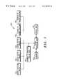
- FIG. 1depicts a block diagram of a computer system having access to data bases for calculating propagation loss of a signal according to various embodiments of the present invention.
- FIG. 2depicts various combinations of a method for calculating propagation loss of a signal, and creating a data base therefore according to various embodiments of the present invention.
- FIG. 3depicts a transportation network and its elements for calculating an environmental factor according to various embodiments of the present invention.
- a propagation loss of a signal transmitted from a transmitter and received at a receiveris determined.
- the receiverin particular is in a predefined area.
- the predefined areahas an elevation profile and a clutter profile.
- the predefined areamay include one or more roads.
- an environmental factoris calculated based on a road density, a population density, a road constant and a road orientation constant, all associated with the predefined area.
- the road constantis based on a predefined road class normally found in the predefined area.
- the road orientation constantis based on an angle of the signal propagation direction from the transmitter to the receiver and a direction of the road where the receiver has an adequate proximity.
- the elevation profileis modified according to the environmental factor to produce a modified elevation profile.
- the propagation lossis determined based on the modified elevation profile and the clutter profile.
- the elevation profilemay be modified according to the clutter profile.
- a propagation loss of a signal transmitted from a transmitter and received at a receiveris determined.
- the receiverin particular is in a predefined area.
- the areahas an elevation profile and a clutter profile.
- the predefined areamay include one or more roads.
- an environmental factoris calculated based on a road density, a population density, a road constant and a road orientation constant, all associated with the predefined area.
- the road constantis based on a predefined road class normally found in the predefined area.
- the road orientation constantis based on an angle of the signal propagation direction from the transmitter to the receiver and a direction of a road where the receiver has an adequate proximity.
- a preliminary propagation lossis determined based on the elevation profile and the clutter profile.
- the preliminary propagation lossis modified according to the environmental factor to produce the propagation loss.
- the preliminary propagation lossmay be modified according to the clutter profile.
- a propagation loss of a signal transmitted from a transmitter and received at a receiveris determined.
- the receiverparticularly is in a predefined area.
- the areahas an elevation profile and a clutter profile.
- the predefined areamay include one or more roads.
- a first and second environmental factorsare calculated based on a road density, a population density, a road constant and a road orientation constant, all associated with the predefined area.
- the road constantis based on a predefined road class normally found in the predefined area.
- the road orientation constantis based on an angle of the signal propagation direction from the transmitter to the receiver and a direction of a road where the receiver has an adequate proximity.
- the elevation profileis modified according to the first environmental factor to produce a modified elevation factor.
- a preliminary propagation lossis determined based on the modified elevation factor and the clutter profile.
- the preliminary propagation lossis modified according to the second environmental factor to produce the propagation loss.
- the elevation profilemay be modified according to the clutter profile.
- the preliminary propagation lossmay be modified according to the clutter profile.
- a method of creating a data base used for calculating a propagation loss of a signal transmitting from a transmitter, receiving by a receiver located in proximity of a road, and propagating through a propagation environmentincludes providing a preliminary data base including at least: a location profile of the transmitter, a location profile of the receiver, an elevation profile of the propagation environment, and a road profile of the propagation environment including at least a road density profile and a road classification profile.
- Further stepsinclude defining an area a surrounding a location of the receiver located within the propagation environment, calculating a road density constant based on the road profile of the area, calculating a road constant based on the road classification profile of the road, calculating an environmental factor by summing the road density constant, and the road constant, and modifying the preliminary data base according to the environmental factor to produce the data base.
- the elevation profilemay be modified according to the clutter profile.
- the preliminary data basefurther includes a population profile of the propagation environment, and the method further includes a step of calculating a population density constant of the area.
- the environmental factorthen incorporates the population density constant.
- the methodfurther includes the step of calculating a road orientation constant based on an angle of the signal propagation direction and a direction of the road obtained from the road density profile, and incorporating the road orientation constant in calculating the environmental factor.
- the usermay selectively remove all or part of the clutter information from the database for the coverage area, or turn off the inclusion of clutter information completely in the propagation loss determination. This decision is based on the user's evaluation of the quality or availability of the clutter data throughout the coverage area.
- Computer system 100normally includes a central processing unit 101 , a keyboard 103 , and a display unit 102 for possible interaction with a user.
- Central processing unit 101has access to various terrain information databases.
- the databasesinclude population data 110 by area, elevation profile data 120 , clutter profile data 130 , traffic profile data 140 , communication system transmitter locations 150 and receiver locations 160 .
- Elevation profile data 120 , clutter profile data 130 and traffic profile data 140may be in a digital format for ease of usability in the computer system 100 .
- a computer program loaded in computer system 100calculates propagation loss of a signal transmitted and received in the communication system according to various embodiments of the present invention. The signal is transmitted from a transmitter identified in transmitter locations 150 database and received by a receiver identified in receiver locations 160 database.
- a flow chart 200depicts various combinations of a method, according to various embodiments of the present invention, for calculating propagation loss of a signal.
- the flow chartis implemented by way of a computer program in computer system 100 .
- several information parametersmust be retrieved from databases accessible by computer system 100 . These information parameters are: a transmitter location 202 , a receiver location 203 , an elevation profile 204 of the signal propagation environment between locations 202 and 203 , and a clutter profile 205 of the signal propagation environment between locations 202 and 203 .
- These information parameters 202 - 205may be retrieved in any logical order without departing from the scope of the present invention.
- the computer programdecides whether to modify elevation profile 204 before it passes to a next step. If the decision is positive, elevation profile 204 is modified in 207 according to clutter profile 205 . After modification in step 207 , a modified version of elevation profile 204 passes to step 208 . Otherwise, if the decision at step 206 is negative, elevation profile 204 without any modification passes to step 208 .
- the computer programdecides whether to modify elevation profile 204 according to a first environmental factor (E1). If decision step 208 is positive, E1 factor is calculated at step 209 . The details of calculating E1 are explained in the following paragraphs.
- the elevation profile received at step 208is modified according to E1 value calculated in step 210 .
- the modified elevation profile at step 210passes to step 211 . Otherwise, if the decision at step 208 is negative, the elevation profile received at step 208 passes to step 211 .
- a preliminary path loss 218 of a signal propagated from transmit location 202 and received at receiver location 203is calculated using a standard path loss calculation method based on the elevation profile received at step 211 .
- Other terrain information parametersmay be involved in calculating path loss at step 211 , however, they are not shown here.
- Several methods for calculating path loss at step 211are available and have been described fully in published literature. Few such methods are Longley-Rice, Durkin's, and Hata; these methods are described in a book titled: Wireless Communications: Principles and Practice, by Theodore S. Rappaport, IEEE Press, pp. 110-120.
- a decisionis made in step 212 whether to modify path loss 218 based on clutter information 205 . If the decision is positive, path loss 218 is modified at step 213 based on clutter information 205 , and the modified path loss at step 213 passes to step 215 . Otherwise, if the decision at step 212 is negative, path loss 218 without modification passes to step 215 .
- a decisionis made according to a user selection whether to modify the path loss received at step 215 according to a second environmental factor (E2).
- E2is calculated at step 214
- the received path loss at step 215is modified according to a value of E2 calculated at step 216 .
- the modified path loss at step 216passes to a final step 217 for outputting a completed path loss calculation 220 . Otherwise, if the decision at step 215 is negative, the received path loss at step 215 passes directly to final step 217 for outputting a completed path loss calculation 220 .
- E1 or E2informations about transportation networks, such as roads, railways, waterways and alike, which are laid out in the signal propagation environment are needed. Normally, such networks are at or near the surface of the earth. In addition, information about population density of the signal propagation environment may be needed when calculating E1 or E2. Databases describing transportation networks and population densities of various areas are readily available. Moreover, these databases are easily and inexpensively updated. According to one advantage of the present invention, use of such inexpensive and updated databases for calculating a propagation path loss involving E1 or E2 eliminates, or reduces, a need for updating clutter information which is expensive and time consuming to obtain.
- a road map of the areamay be used to generate the transportation network database. Generating a transportation network database is much easier than generating a clutter information database.
- E1 or E2is a function of road density (RD), population density (PD), road category (RC), and road orientation (RD) parameters. Summation of RD, PD, RC and RD, while multiplying a weight factor to each parameter, produces E1 or E2. Although the weight factors or value of parameters may be different for E1 and E2 calculations, a process of calculating E1 is equally applicable to a process of calculating E2.
- a transportation networkmay include many different categories of transportation networks such as roads, waterways, and alike. Furthermore, each category of transportation network may be divided into many classifications. For example, the Census Feature Class Code (CFCC) classification system, available from the United States Geological Survey, provides approximately 44 different classifications of roads. Primary highways with and without limited access, secondary and connecting roads, local and neighborhood roads are several examples of such road classifications.
- FIG. 3depicts a road network 300 which is comprised of a number of small roads 320 , generally indicating a residential road class, a number of medium sized roads 330 , generally indicating a secondary and connecting road class, and a large road 340 , generally indicating a primary highway class. It may be observed in FIG. 3 that each road class is shown by a different line thickness.
- a subregion 350is selected for further analysis of the transportation network between a receiver location 303 and a transmitter location 302 .
- Subregion 350at least includes receiver 303 .
- Receiver 303may be a cellular mobile receiver, and transmitter 302 may be a cellular base station in a cellular communication system.
- Subregion 350lies primarily along a signal propagation path between transmitter 302 and receiver 303 .
- Subregion 350is selected such that receiver 303 lies generally at an edge or near an edge of an area defined by subregion 350 .
- An edge 351is shown to be the nearest edge to receiver 303 . Also, edge 351 of subregion 350 is on a side of subregion 350 that is furthest from transmitter 302 .
- subregion 350 containing receiver location 303may be modified to account for terrain fluctuations or unique properties, such as non-uniform road categories or population densities of subregion 350 , without departing from the scope of the present invention.
- the size, shape and relationship of subregion 350 containing receiver 303 locationmay be modified, in certain geographical situations, to place edge 351 at a furthest location from transmitter 302 and nearest to receiver 303 .
- Subregion 350is divided into a number of tiles, such as 360 , 361 , 362 , and 363 .
- a nominal size of a square tileis approximately 100 m on a side. However, other tile shapes and sizes may be used. Each tile is evaluated according to a road that lies within the tile.
- tile 360does not contain any road, therefore, it is assigned a tile reference number equal to zero.
- Tile 361contains road class 330 , a road class of 2 according to CFCC, representing a secondary and connecting road, therefore, it is assigned a reference number equal to two.
- Tile 362contains a road class 340 , a road class of 1 according to CFCC, representing a primary highway, therefore, it is assigned a tile reference number equal to one.
- Tile 363contains a road class 311 , a road class of 4 according to CFCC, representing a residential road class, therefore, it is assigned a tile reference number equal to four. Although a CFCC classification system is followed here, any other type of classification system may equally be substituted.
- E1 or E2may be represented by a summation as follows:
- a, b, c and dare weighting factors.
- the weighting factorsare specified by a user to scale contribution of each parameter in the summation.
- the f(RD)is a predefined function of the road density (RD). RD defines a percentage number of tiles in subregion 350 that contains a road.
- the f(RD)is represented by:
- the f(PD)defines a predefined function of a population density (PD) of subregion 350 .
- the population density PDmay be defined according to a time of day, and is normally in unit of people per unit area.
- the f(PD)is represented by:
- the f(RC)is a predefined function of a road class (RC) of a tile where the receiver is located.
- the RCis the evaluated road class assigned to tile 361 . If RC value is greater than or equal to a constant “p” and less than or equal to a constant “q”, f(RC) is equal to a constant “r”, otherwise, f(RC) is equal to a constant “s”.
- the constants p, q, r and sare predefined.
- the f(RO)is a predefined function of a road orientation (RO).
- Each receiversuch as receiver 303 , normally is located on or near a road as shown in FIG. 3 .
- the road near receiver 303would have an orientation angle, theta, 370 with respect to a line of signal propagation from transmitter 302 to receiver 302 .
- the f(RO)is represented by:
- E1modifies an elevation profile in units of height
- E2modifies a propagation loss in units of decibels.
- the values of a, b, c, and dare generally specified for a given range depending on the characteristics of the coverage area. They may also be a function of the values stored in the clutter database for the location being evaluated.
- the values for a, b, c and dare designed to adjust contribution of each parameter in E1 and E2. Based on some actual field measurements, the values of a, b, c, and d are adjusted to achieve the minimum root mean squared (rms) error for the propagation prediction of multiple locations throughout a test area. Adjusting or tuning parameters in this way to achieve the best (rms) fit to actual measurements is a well known engineering principal.
- the a, b, c, and d valuesbe different for different areas depending on the nature of the environment, the density of the city, and the size of the roads, and alike.
- a, b, c, and d valuesmay be stored in a table. In some cases, for example, the population data 110 may not be available in certain country.
- the value for bmay be set to zero, so that the contribution from f(PD) would be equal to zero in calculating E1 or E2.
- the values for a, b, c, and d for calculating E1 and E2may be different.
- a computer program based on various embodiments of the present inventionmay be incorporated in a simulation tool predicating a cellular communication system coverage area.
- Such toolsnormally, predict signal propagation path loss between a base station and various mobile units in the coverage area.
- a communication system designeris able to determine the number of users that may be served in the coverage area before base station installation takes place.
- various objects, such as homes, buildings, bridges and roadsare erected or demolished in the coverage area, the system designer is able to maintain the communication system efficiency by assuring adequate service to the users by continuously adjusting the system capacity based on the simulation results.
- a computer program known as Netplanis available from Motorola Inc. that performs propagation simulation. Information about Netplan is available by contacting Motorola Inc.
Landscapes
- Engineering & Computer Science (AREA)
- Computer Networks & Wireless Communication (AREA)
- Signal Processing (AREA)
- Physics & Mathematics (AREA)
- Electromagnetism (AREA)
- Traffic Control Systems (AREA)
Abstract
Description
Claims (13)
Priority Applications (1)
| Application Number | Priority Date | Filing Date | Title |
|---|---|---|---|
| US09/030,091US6289203B1 (en) | 1998-02-25 | 1998-02-25 | Method of calculating signal propagation loss and creating a data base therefor |
Applications Claiming Priority (1)
| Application Number | Priority Date | Filing Date | Title |
|---|---|---|---|
| US09/030,091US6289203B1 (en) | 1998-02-25 | 1998-02-25 | Method of calculating signal propagation loss and creating a data base therefor |
Publications (1)
| Publication Number | Publication Date |
|---|---|
| US6289203B1true US6289203B1 (en) | 2001-09-11 |
Family
ID=21852452
Family Applications (1)
| Application Number | Title | Priority Date | Filing Date |
|---|---|---|---|
| US09/030,091Expired - LifetimeUS6289203B1 (en) | 1998-02-25 | 1998-02-25 | Method of calculating signal propagation loss and creating a data base therefor |
Country Status (1)
| Country | Link |
|---|---|
| US (1) | US6289203B1 (en) |
Cited By (29)
| Publication number | Priority date | Publication date | Assignee | Title |
|---|---|---|---|---|
| US20020058503A1 (en)* | 2000-09-26 | 2002-05-16 | Gutowski Stan J. | Path loss data normalization for growth management of a cellular system |
| US20020077787A1 (en)* | 2000-12-18 | 2002-06-20 | Theodore Rappaport | Textual and graphical demarcation of location, and interpretation of measurements |
| US6499006B1 (en)* | 1999-07-14 | 2002-12-24 | Wireless Valley Communications, Inc. | System for the three-dimensional display of wireless communication system performance |
| US20030023412A1 (en)* | 2001-02-14 | 2003-01-30 | Rappaport Theodore S. | Method and system for modeling and managing terrain, buildings, and infrastructure |
| US20030050878A1 (en)* | 1999-05-26 | 2003-03-13 | Rappaport Theodore S. | Method and system for generating a real time bill of materials and evaluating network performance |
| US6580911B1 (en)* | 1999-08-06 | 2003-06-17 | Ericsson Inc. | Clutter database enhancement methodology |
| US6721769B1 (en) | 1999-05-26 | 2004-04-13 | Wireless Valley Communications, Inc. | Method and system for a building database manipulator |
| US20040127224A1 (en)* | 2002-10-23 | 2004-07-01 | Hiroshi Furukawa | Base-station cell design method and base-station cell design apparatus, and program thereof in mobile communication system |
| US20040143428A1 (en)* | 2003-01-22 | 2004-07-22 | Rappaport Theodore S. | System and method for automated placement or configuration of equipment for obtaining desired network performance objectives |
| US20040229623A1 (en)* | 1999-05-26 | 2004-11-18 | Rappaport Theodore S. | Method and system for analysis, design, and optimization of communication networks |
| US20040259554A1 (en)* | 2003-04-23 | 2004-12-23 | Rappaport Theodore S. | System and method for ray tracing using reception surfaces |
| US20040259555A1 (en)* | 2003-04-23 | 2004-12-23 | Rappaport Theodore S. | System and method for predicting network performance and position location using multiple table lookups |
| US20050043933A1 (en)* | 2000-08-04 | 2005-02-24 | Theodore Rappaport | System and method for efficiently visualizing and comparing communication network system performance |
| US6876951B2 (en) | 1998-12-29 | 2005-04-05 | Wireless Valley Communications, Inc. | Method for creating a computer model and measurement database of a wireless communication network |
| US6971063B1 (en) | 2000-07-28 | 2005-11-29 | Wireless Valley Communications Inc. | System, method, and apparatus for portable design, deployment, test, and optimization of a communication network |
| US20050265321A1 (en)* | 2000-09-25 | 2005-12-01 | Theodore Rappaport | System and method for design, tracking, measurement, prediction and optimization of data communication networks |
| US7055107B1 (en) | 2000-09-22 | 2006-05-30 | Wireless Valley Communications, Inc. | Method and system for automated selection of optimal communication network equipment model, position, and configuration |
| US20060116853A1 (en)* | 2001-12-17 | 2006-06-01 | Theodore Rappaport | Textual and graphical demarcation of location, and interpretation of measurments |
| US7085697B1 (en) | 2000-08-04 | 2006-08-01 | Motorola, Inc. | Method and system for designing or deploying a communications network which considers component attributes |
| US7096173B1 (en) | 2000-08-04 | 2006-08-22 | Motorola, Inc. | Method and system for designing or deploying a communications network which allows simultaneous selection of multiple components |
| US7171208B2 (en) | 2000-08-04 | 2007-01-30 | Motorola, Inc. | Method and system, with component kits for designing or deploying a communications network which considers frequency dependent effects |
| US7243054B2 (en) | 1999-07-14 | 2007-07-10 | Wireless Valley Communications, Inc. | Method and system for displaying network performance, cost, maintenance, and infrastructure wiring diagram |
| US7295119B2 (en) | 2003-01-22 | 2007-11-13 | Wireless Valley Communications, Inc. | System and method for indicating the presence or physical location of persons or devices in a site specific representation of a physical environment |
| US7680644B2 (en) | 2000-08-04 | 2010-03-16 | Wireless Valley Communications, Inc. | Method and system, with component kits, for designing or deploying a communications network which considers frequency dependent effects |
| WO2017015076A1 (en)* | 2015-07-17 | 2017-01-26 | Clearsky Technologies, Inc. | Method of placing an antenna of a radio access network (ran) asset in a wireless communication network |
| US10274602B2 (en)* | 2014-07-14 | 2019-04-30 | Iposi, Inc. | Tomographic loss factor estimation |
| US10511417B2 (en) | 2004-05-01 | 2019-12-17 | Intellectual Ventures Ii Llc | Methods and apparatus for multi-carrier communications with variable channel bandwidth |
| US10743284B2 (en) | 2006-05-02 | 2020-08-11 | Intellectual Ventures Ii Llc | Paging in a wireless network |
| US11191037B2 (en)* | 2017-03-23 | 2021-11-30 | Interdigital Patent Holdings, Inc. | Altitude path-loss based power control for aerial vehicles |
Citations (5)
| Publication number | Priority date | Publication date | Assignee | Title |
|---|---|---|---|---|
| US5179722A (en)* | 1989-12-18 | 1993-01-12 | Krister Gunmar | Method for determining multiple interference in a mobile radio system |
| US5491644A (en)* | 1993-09-07 | 1996-02-13 | Georgia Tech Research Corporation | Cell engineering tool and methods |
| US5561841A (en)* | 1992-01-23 | 1996-10-01 | Nokia Telecommunication Oy | Method and apparatus for planning a cellular radio network by creating a model on a digital map adding properties and optimizing parameters, based on statistical simulation results |
| US5828960A (en)* | 1995-03-31 | 1998-10-27 | Motorola, Inc. | Method for wireless communication system planning |
| US5953669A (en)* | 1997-12-11 | 1999-09-14 | Motorola, Inc. | Method and apparatus for predicting signal characteristics in a wireless communication system |
- 1998
- 1998-02-25USUS09/030,091patent/US6289203B1/ennot_activeExpired - Lifetime
Patent Citations (5)
| Publication number | Priority date | Publication date | Assignee | Title |
|---|---|---|---|---|
| US5179722A (en)* | 1989-12-18 | 1993-01-12 | Krister Gunmar | Method for determining multiple interference in a mobile radio system |
| US5561841A (en)* | 1992-01-23 | 1996-10-01 | Nokia Telecommunication Oy | Method and apparatus for planning a cellular radio network by creating a model on a digital map adding properties and optimizing parameters, based on statistical simulation results |
| US5491644A (en)* | 1993-09-07 | 1996-02-13 | Georgia Tech Research Corporation | Cell engineering tool and methods |
| US5828960A (en)* | 1995-03-31 | 1998-10-27 | Motorola, Inc. | Method for wireless communication system planning |
| US5953669A (en)* | 1997-12-11 | 1999-09-14 | Motorola, Inc. | Method and apparatus for predicting signal characteristics in a wireless communication system |
Non-Patent Citations (4)
| Title |
|---|
| 1996 IEEE 46th Vehicular Technology Conference Proceedings, vol. 3, IEEE Service Center, 445 Hoes Lane, PO Box 1331, Piscataway, NJ 088855, Cat. Nos.: 96CH35894, 96CB35894. |
| Census Feature Class Codes, tiger/line files, 1995 Technical Documentation, Bureau of the Census, Washington DC, 1996. |
| Net Plan RF Engineering User's Manual, Release 3.1, 1197, Motorola Inc. |
| Wireless Communications Principles and Practice, by T. S. Rappaport, pp. 110-120, 1996, Prentice Hall, upper Saddle River, New Jersey 07458. |
Cited By (61)
| Publication number | Priority date | Publication date | Assignee | Title |
|---|---|---|---|---|
| US7096160B2 (en) | 1998-12-29 | 2006-08-22 | Wireless Valley Communications, Inc. | System and method for measuring and monitoring wireless network performance in campus and indoor environments |
| US6876951B2 (en) | 1998-12-29 | 2005-04-05 | Wireless Valley Communications, Inc. | Method for creating a computer model and measurement database of a wireless communication network |
| US20030050878A1 (en)* | 1999-05-26 | 2003-03-13 | Rappaport Theodore S. | Method and system for generating a real time bill of materials and evaluating network performance |
| US20040177085A1 (en)* | 1999-05-26 | 2004-09-09 | Theodore Rappaport | Method and system for using raster images to create a transportable building database for communications network engineering and management |
| US7596518B2 (en) | 1999-05-26 | 2009-09-29 | Wireless Valley Communications, Inc. | Method and system for generating a real time bill of materials and evaluating network performance |
| US20050131619A1 (en)* | 1999-05-26 | 2005-06-16 | Rappaport Theodore S. | Method and system for a building database manipulator |
| US7711687B2 (en) | 1999-05-26 | 2010-05-04 | Wireless Valley Communications, Inc. | Method and system for using raster images to create a transportable building database for communications network engineering and management |
| US6721769B1 (en) | 1999-05-26 | 2004-04-13 | Wireless Valley Communications, Inc. | Method and system for a building database manipulator |
| US6850946B1 (en) | 1999-05-26 | 2005-02-01 | Wireless Valley Communications, Inc. | Method and system for a building database manipulator |
| US7155228B2 (en) | 1999-05-26 | 2006-12-26 | Wireless Valley Communications, Inc. | Method and system for analysis, design, and optimization of communication networks |
| US20040162840A1 (en)* | 1999-05-26 | 2004-08-19 | Theodore Rappaport | System and method for a three dimensional database modeler for wireless communications network management and engineering |
| US20040229623A1 (en)* | 1999-05-26 | 2004-11-18 | Rappaport Theodore S. | Method and system for analysis, design, and optimization of communication networks |
| US20040186847A1 (en)* | 1999-05-26 | 2004-09-23 | Rappaport Theodore S. | Method and apparatus for a transportable environmental database for communications network management and engineering |
| US20030014233A1 (en)* | 1999-07-14 | 2003-01-16 | Rappaport Theodore S. | System for the three-dimensional display of wireless communication system performance |
| US7243054B2 (en) | 1999-07-14 | 2007-07-10 | Wireless Valley Communications, Inc. | Method and system for displaying network performance, cost, maintenance, and infrastructure wiring diagram |
| US6499006B1 (en)* | 1999-07-14 | 2002-12-24 | Wireless Valley Communications, Inc. | System for the three-dimensional display of wireless communication system performance |
| US7299168B2 (en) | 1999-07-14 | 2007-11-20 | Wireless Valley Communications, Inc. | System for the three-dimensional display of wireless communication system performance |
| US6580911B1 (en)* | 1999-08-06 | 2003-06-17 | Ericsson Inc. | Clutter database enhancement methodology |
| US20060015814A1 (en)* | 2000-07-28 | 2006-01-19 | Rappaport Theodore S | System, method, and apparatus for portable design, deployment, test, and optimization of a communication network |
| US6971063B1 (en) | 2000-07-28 | 2005-11-29 | Wireless Valley Communications Inc. | System, method, and apparatus for portable design, deployment, test, and optimization of a communication network |
| US7933605B2 (en) | 2000-08-04 | 2011-04-26 | Motorola Solutions, Inc. | Method and system, with component kits for designing or deploying a communications network which considers frequency dependent effects |
| US20050043933A1 (en)* | 2000-08-04 | 2005-02-24 | Theodore Rappaport | System and method for efficiently visualizing and comparing communication network system performance |
| US7286971B2 (en) | 2000-08-04 | 2007-10-23 | Wireless Valley Communications, Inc. | System and method for efficiently visualizing and comparing communication network system performance |
| US7246045B1 (en) | 2000-08-04 | 2007-07-17 | Wireless Valley Communication, Inc. | System and method for efficiently visualizing and comparing communication network system performance |
| US8290499B2 (en) | 2000-08-04 | 2012-10-16 | Wireless Valley Communications Inc. | Method and system to model frequency dependent effects of a communciations network |
| US7680644B2 (en) | 2000-08-04 | 2010-03-16 | Wireless Valley Communications, Inc. | Method and system, with component kits, for designing or deploying a communications network which considers frequency dependent effects |
| US7171208B2 (en) | 2000-08-04 | 2007-01-30 | Motorola, Inc. | Method and system, with component kits for designing or deploying a communications network which considers frequency dependent effects |
| US7085697B1 (en) | 2000-08-04 | 2006-08-01 | Motorola, Inc. | Method and system for designing or deploying a communications network which considers component attributes |
| US7096173B1 (en) | 2000-08-04 | 2006-08-22 | Motorola, Inc. | Method and system for designing or deploying a communications network which allows simultaneous selection of multiple components |
| US7055107B1 (en) | 2000-09-22 | 2006-05-30 | Wireless Valley Communications, Inc. | Method and system for automated selection of optimal communication network equipment model, position, and configuration |
| US8503336B2 (en) | 2000-09-25 | 2013-08-06 | Wireless Valley Communications, Inc | System and method for design, tracking, measurement, prediction and optimization of data communication networks |
| US6973622B1 (en) | 2000-09-25 | 2005-12-06 | Wireless Valley Communications, Inc. | System and method for design, tracking, measurement, prediction and optimization of data communication networks |
| US20050265321A1 (en)* | 2000-09-25 | 2005-12-01 | Theodore Rappaport | System and method for design, tracking, measurement, prediction and optimization of data communication networks |
| US7035632B2 (en)* | 2000-09-26 | 2006-04-25 | Scoreboard, Inc. | Path loss data normalization for growth management of a cellular system |
| US20020058503A1 (en)* | 2000-09-26 | 2002-05-16 | Gutowski Stan J. | Path loss data normalization for growth management of a cellular system |
| US20020077787A1 (en)* | 2000-12-18 | 2002-06-20 | Theodore Rappaport | Textual and graphical demarcation of location, and interpretation of measurements |
| US7019753B2 (en) | 2000-12-18 | 2006-03-28 | Wireless Valley Communications, Inc. | Textual and graphical demarcation of location from an environmental database, and interpretation of measurements including descriptive metrics and qualitative values |
| US7164883B2 (en) | 2001-02-14 | 2007-01-16 | Motorola. Inc. | Method and system for modeling and managing terrain, buildings, and infrastructure |
| US20030023412A1 (en)* | 2001-02-14 | 2003-01-30 | Rappaport Theodore S. | Method and system for modeling and managing terrain, buildings, and infrastructure |
| US20060116853A1 (en)* | 2001-12-17 | 2006-06-01 | Theodore Rappaport | Textual and graphical demarcation of location, and interpretation of measurments |
| US7574323B2 (en) | 2001-12-17 | 2009-08-11 | Wireless Valley Communications, Inc. | Textual and graphical demarcation of location, and interpretation of measurements |
| US20040127224A1 (en)* | 2002-10-23 | 2004-07-01 | Hiroshi Furukawa | Base-station cell design method and base-station cell design apparatus, and program thereof in mobile communication system |
| US7079844B2 (en)* | 2002-10-23 | 2006-07-18 | Nec Corporation | Base-station cell design method and base-station cell design apparatus, and program thereof in mobile communication system |
| US20060142014A1 (en)* | 2002-10-23 | 2006-06-29 | Hiroshi Furukawa | Base-station cell design method and base-station cell design apparatus, and program thereof in mobile communication system |
| US8135421B2 (en) | 2002-10-23 | 2012-03-13 | Nec Corporation | Base-station cell design method and base-station cell design apparatus, and program thereof in mobile communication system |
| US7295119B2 (en) | 2003-01-22 | 2007-11-13 | Wireless Valley Communications, Inc. | System and method for indicating the presence or physical location of persons or devices in a site specific representation of a physical environment |
| US20040143428A1 (en)* | 2003-01-22 | 2004-07-22 | Rappaport Theodore S. | System and method for automated placement or configuration of equipment for obtaining desired network performance objectives |
| US20040259555A1 (en)* | 2003-04-23 | 2004-12-23 | Rappaport Theodore S. | System and method for predicting network performance and position location using multiple table lookups |
| US20040259554A1 (en)* | 2003-04-23 | 2004-12-23 | Rappaport Theodore S. | System and method for ray tracing using reception surfaces |
| US10511417B2 (en) | 2004-05-01 | 2019-12-17 | Intellectual Ventures Ii Llc | Methods and apparatus for multi-carrier communications with variable channel bandwidth |
| US12341712B2 (en) | 2004-05-01 | 2025-06-24 | Intellectual Ventures Ii Llc | Methods and apparatus for multi-carrier communications with variable channel bandwidth |
| US11082172B2 (en) | 2004-05-01 | 2021-08-03 | Intellectual Ventures Ii Llc | Methods and apparatus for multi-carrier communications with variable channel bandwidth |
| US11792769B2 (en) | 2006-05-02 | 2023-10-17 | Intellectual Ventures Ii Llc | Paging in a wireless network |
| US10743284B2 (en) | 2006-05-02 | 2020-08-11 | Intellectual Ventures Ii Llc | Paging in a wireless network |
| US11564202B2 (en) | 2006-05-02 | 2023-01-24 | Intellectual Ventures Ii Llc | Paging in a wireless network |
| US12082153B2 (en) | 2006-05-02 | 2024-09-03 | Intellectual Ventures Ii Llc | Paging in a wireless network |
| US12418888B2 (en) | 2006-05-02 | 2025-09-16 | Intellectual Ventures Ii Llc | Paging in a wireless network |
| US10274602B2 (en)* | 2014-07-14 | 2019-04-30 | Iposi, Inc. | Tomographic loss factor estimation |
| US10080143B2 (en) | 2015-07-17 | 2018-09-18 | Clearsky Technologies, Inc. | Method of placing an antenna of a radio access network (RAN) asset in a wireless communication network |
| WO2017015076A1 (en)* | 2015-07-17 | 2017-01-26 | Clearsky Technologies, Inc. | Method of placing an antenna of a radio access network (ran) asset in a wireless communication network |
| US11191037B2 (en)* | 2017-03-23 | 2021-11-30 | Interdigital Patent Holdings, Inc. | Altitude path-loss based power control for aerial vehicles |
Similar Documents
| Publication | Publication Date | Title |
|---|---|---|
| US6289203B1 (en) | Method of calculating signal propagation loss and creating a data base therefor | |
| US11463887B2 (en) | Systems and methods for network coverage optimization and planning | |
| CN111818555B (en) | Radio monitoring station coverage area evaluation and analysis method based on virtual station building | |
| US8611827B2 (en) | System, method, and program for correcting radiowave environment data | |
| JP4499746B2 (en) | Method and apparatus for adapting wireless network model to actual wireless network conditions | |
| CA2472995C (en) | Methods for determining the approximate location of a device from ambient signals | |
| KR100803677B1 (en) | Apparatus and method for statistically analyzing radio signal propagation | |
| CN105163337B (en) | A method of the mobile network data geography mapping based on coverage prediction emulation | |
| US7945435B2 (en) | Search method, search system, and search program | |
| AU2004203018A1 (en) | Systems for determining the approximate location of a device from ambient signals | |
| JP4312480B2 (en) | Method and system for wireless coverage deployment in a mobile wireless telephone network | |
| US20100103868A1 (en) | Method for modeling wireless network coverage under line-of-sight conditions | |
| US20220201500A1 (en) | Methods and systems for resource planning in a shared spectra | |
| WO1994003986A1 (en) | Computer-implemented modelling system for wireless communications systems | |
| KR20060136447A (en) | Method and device for adapting a radio network model to the conditions of a real radio network | |
| US6842726B1 (en) | Method of determining RF coverage area in a point-to-multipoint transmission system | |
| CN108184202B (en) | Method and device for determining coverage scene of base station | |
| KR101504357B1 (en) | Method to extract and represent terrain obstacles for radio network optimization from measured drive-test data | |
| US11533633B2 (en) | Frequency planning for a communication system | |
| Munene et al. | Optimizing the location of base transceiver stations in mobile communication network planning: case study of the Nairobi Central Business District, Kenya | |
| Evans et al. | The optimization and application of the WCY Lee propagation model in the 1900 MHz frequency band | |
| Combeau et al. | A numerical simulation system for mobile telephony base station EMF exposure using smartphones as probes and a genetic algorithm to improve accuracy | |
| Dodd | The validity of using a geographic information system's viewshed function as a predictor for the reception of line-of-sight radio waves | |
| GB2621389A (en) | Small cell deployment | |
| Storsaeter et al. | A GIS-based tool for optimizing C-ITS communication infrastructure |
Legal Events
| Date | Code | Title | Description |
|---|---|---|---|
| AS | Assignment | Owner name:MOTOROLA, INC., ILLINOIS Free format text:ASSIGNMENT OF ASSIGNORS INTEREST;ASSIGNORS:SMITH, JACK ANTHONY;REED, JOHN DOUGLAS;DEWHIRST, ADAM;REEL/FRAME:009134/0930;SIGNING DATES FROM 19980227 TO 19980304 | |
| STCF | Information on status: patent grant | Free format text:PATENTED CASE | |
| FPAY | Fee payment | Year of fee payment:4 | |
| FPAY | Fee payment | Year of fee payment:8 | |
| AS | Assignment | Owner name:MOTOROLA MOBILITY, INC, ILLINOIS Free format text:ASSIGNMENT OF ASSIGNORS INTEREST;ASSIGNOR:MOTOROLA, INC;REEL/FRAME:025673/0558 Effective date:20100731 | |
| AS | Assignment | Owner name:MOTOROLA MOBILITY LLC, ILLINOIS Free format text:CHANGE OF NAME;ASSIGNOR:MOTOROLA MOBILITY, INC.;REEL/FRAME:029216/0282 Effective date:20120622 | |
| FPAY | Fee payment | Year of fee payment:12 | |
| AS | Assignment | Owner name:GOOGLE TECHNOLOGY HOLDINGS LLC, CALIFORNIA Free format text:ASSIGNMENT OF ASSIGNORS INTEREST;ASSIGNOR:MOTOROLA MOBILITY LLC;REEL/FRAME:034305/0001 Effective date:20141028 |