US6289113B1 - Handheld iris imaging apparatus and method - Google Patents
Handheld iris imaging apparatus and methodDownload PDFInfo
- Publication number
- US6289113B1 US6289113B1US09/200,214US20021498AUS6289113B1US 6289113 B1US6289113 B1US 6289113B1US 20021498 AUS20021498 AUS 20021498AUS 6289113 B1US6289113 B1US 6289113B1
- Authority
- US
- United States
- Prior art keywords
- image
- iris
- focus
- imaging apparatus
- indicator
- Prior art date
- Legal status (The legal status is an assumption and is not a legal conclusion. Google has not performed a legal analysis and makes no representation as to the accuracy of the status listed.)
- Expired - Lifetime
Links
Images


Classifications
- G—PHYSICS
- G06—COMPUTING OR CALCULATING; COUNTING
- G06V—IMAGE OR VIDEO RECOGNITION OR UNDERSTANDING
- G06V40/00—Recognition of biometric, human-related or animal-related patterns in image or video data
- G06V40/10—Human or animal bodies, e.g. vehicle occupants or pedestrians; Body parts, e.g. hands
- G06V40/18—Eye characteristics, e.g. of the iris
- G06V40/19—Sensors therefor
- G—PHYSICS
- G06—COMPUTING OR CALCULATING; COUNTING
- G06V—IMAGE OR VIDEO RECOGNITION OR UNDERSTANDING
- G06V30/00—Character recognition; Recognising digital ink; Document-oriented image-based pattern recognition
- G06V30/10—Character recognition
- G06V30/14—Image acquisition
- G06V30/142—Image acquisition using hand-held instruments; Constructional details of the instruments
- G—PHYSICS
- G06—COMPUTING OR CALCULATING; COUNTING
- G06V—IMAGE OR VIDEO RECOGNITION OR UNDERSTANDING
- G06V40/00—Recognition of biometric, human-related or animal-related patterns in image or video data
- G06V40/60—Static or dynamic means for assisting the user to position a body part for biometric acquisition
- G06V40/67—Static or dynamic means for assisting the user to position a body part for biometric acquisition by interactive indications to the user
- A—HUMAN NECESSITIES
- A61—MEDICAL OR VETERINARY SCIENCE; HYGIENE
- A61B—DIAGNOSIS; SURGERY; IDENTIFICATION
- A61B3/00—Apparatus for testing the eyes; Instruments for examining the eyes
- A61B3/10—Objective types, i.e. instruments for examining the eyes independent of the patients' perceptions or reactions
- A61B3/12—Objective types, i.e. instruments for examining the eyes independent of the patients' perceptions or reactions for looking at the eye fundus, e.g. ophthalmoscopes
- A61B3/1216—Objective types, i.e. instruments for examining the eyes independent of the patients' perceptions or reactions for looking at the eye fundus, e.g. ophthalmoscopes for diagnostics of the iris
Definitions
- the present inventionrelates in general to identification of physical characteristics of a human being or other animal. More particularly, the present invention relates to iris recognition.
- Various technologiesare used for uniquely identifying a person in accordance with an examination of particular attributes of either the person's interior or exterior eye.
- One of these technologiesinvolves the visual examination of the particular attributes of the exterior of the iris of at least one of the person's eyes.
- the iris of the human eyehas random patterns of striations, ciliary processes, crypts, rings, furrows and other features which had been shown capable of generating highly unique biometric templates for personal identification.
- iris recognitioncan be used for such purposes as controlling access to a secure facility or a bank automatic teller machine, for example.
- An iris recognition systeminvolves the use of an imager to video image the iris of each person attempting access, and image processing means for comparing this iris video image with a reference iris image on file in a database.
- Iris identification systemshave been developed that are capable of collecting images of the iris and processing them to produce biometric templates. These templates may be used to identify individual irises with extremely low error rates, on the order of 1 in 10 78 .
- the systemscapture the iris images using stationary optical platforms that are often large, complex, and expensive. The systems are difficult to use with minimal cooperation of the subject being identified. As a result their usefulness in many applications is limited.
- the present inventionis directed to a handheld iris imaging apparatus for obtaining an image of an iris of an eye, comprising: iris acquisition means having a front surface; a lens having a image plane disposed in front of the front surface of the iris acquisition means; a mirror disposed on a side of the lens opposite the iris acquisition means; and an illuminator disposed along a side of the mirror.
- the iris acquisition meanscomprises a camera, and the mirror is a cold mirror.
- the camerais sensitive to light having a wavelength in a range between about 400 nm and about 1100 nm.
- the mirrorreflects light having a wavelength in a range between about 400 nm and about 700 nm and passes light having a wavelength greater than about 700 nm.
- the illuminatoremits light having a wavelength in a range between about 680 nm and about 900 nm towards the iris of the eye being imaged, the eye being out of contact with the iris imaging apparatus.
- the iris imaging apparatusfurther comprises at least a visible indicator or an audible indicator to indicate when the image of the iris has been obtained.
- a further embodiment within the scope of the present inventionis directed to a method of obtaining an iris image of a subject, comprising the steps of: (a) illuminating an iris of the subject; (b) forming an approximately centered image of the iris at an image plane of a camera; (c) storing the image in a memory; (d) determining if the image is an image of sufficient quality; and (e) repeating steps (a) through (d) until the image of sufficient quality is obtained.
- the methodfurther comprises the step of activating an indicator if the image is of insufficient quality.
- the indicatoris an audible indicator.
- the methodfurther comprises the step of activating an indicator if the image is of sufficient quality.
- the indicatoris a visible indicator.
- the methodfurther comprises the step of displaying the image on a display.
- a further embodiment within the scope of the present inventionis directed to a system of identification, comprising: a handheld imaging apparatus; a first memory for storing at least one template of at least one image of an iris of at least one person's eye; a second memory for storing a template of an iris image obtained by the iris acquisition means; and a comparator for comparing the template of the iris image of the second memory with the at least one stored template of the first memory to identify the person.
- the iris acquisition meanscomprises a camera, and the mirror is a cold mirror.
- the comparatorcomprises a processor responsive to an output of the camera for comparing the template of the second memory with the at least one stored template of the first memory.
- the first memory, the second memory, and the comparatorare disposed in a housing that is separate from the handheld iris imaging apparatus.
- the housingis coupled to the handheld iris imaging apparatus by a wireless modem.
- the systemfurther comprises at least one of a visible indicator and an audible indicator disposed within the handheld iris imaging apparatus.
- the systemfurther comprises a focus assessment processor coupled to the at least one of a visible indicator and an audible indicator.
- the systemfurther comprises a display disposed within the handheld iris imaging apparatus.
- a further embodiment within the scope of the present inventionis directed to a method of identification of a person, comprising the steps of: (a) storing image information of the iris of at least one person's eye; (b) illuminating an eye of an unidentified person having an iris; (c) obtaining an image of the iris of the unidentified person; (d) storing the image in a memory; (e) determining if the image is an image of sufficient quality for a step (g) of comparing; (f) repeating steps (b) through (e) until the image of sufficient quality is obtained; and (g) comparing a template of the obtained image with the stored image information to identify the unidentified person.
- the methodfurther comprises the step of activating an indicator if the image is of insufficient quality.
- the indicatoris an audible indicator.
- the methodfurther comprises the step of activating an indicator if the image is of sufficient quality.
- the indicatoris a visible indicator.
- the step of determining if the image is an image of sufficient qualitycomprises the step of focus assessment processing the image.
- the methodfurther comprises the step of displaying the image on a display.
- FIG. 1is a schematic diagram of an exemplary iris imager in accordance with the present invention
- FIG. 2Ais a schematic diagram of the imager of FIG. 1 shown in greater detail
- FIG. 2Bis a schematic diagram of another exemplary imager in accordance with the present invention.
- FIG. 3is a simplified flowchart of a method of operation in accordance with the present invention.
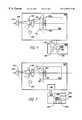
- FIG. 4is a schematic diagram of an exemplary iris image recognition system in accordance with the present invention.
- FIG. 5is a schematic diagram of another exemplary iris image recognition system in accordance with the present invention.
- FIG. 6is a schematic diagram of an exemplary iris imager having visual and aural indicators in accordance with the present invention.
- FIG. 7is a more detailed flow chart of a method of operation in accordance with the present invention.
- FIG. 8is a schematic diagram of an exemplary iris image recognition system having a focus assessment processor in accordance with the present invention.
- FIG. 9is a schematic diagram of an exemplary iris imager comprising a focus assessment processor in accordance with the present invention.
- FIG. 10is a schematic diagram of an exemplary iris imager comprising a focus assessment processor and image processor in accordance with the present invention.
- the present inventionis directed to a compact, handheld imaging apparatus and method which can be used to capture high-quality iris images.
- the imagerhas sensors and indicators which assist the human operator in aligning and focusing the device.
- the imageralso automatically captures the image when proper positioning is achieved. Because it is small and compact, it is practical for use as an accessory to a personal computer, and for many business and consumer applications where cost is critical.
- FIG. 1illustrates a preferred embodiment of the handheld imager 100 in accordance with the present invention.
- the exemplary handheld, non-invasive, non-contacting iris imagercomprises iris acquisition means 105 , an imaging lens 110 , a mirror 120 , an optional diopter correction lens 125 , and an illuminator 130 .
- the imager 100can be powered by a standard DC or AC supply, and preferably a 9 volt battery (not shown).
- the iris acquisition means 105is preferably a conventional solid state video camera, such as a charged coupled device (CCD) or complementary metal oxide semiconductor (CMOS) device.
- a preferred camerais a ⁇ fraction (1/3 ) ⁇ inch format, monochrome CCD board camera, such as Computar Model EM200.
- the video camera 105is sensitive to light of wavelengths in the range of about 400 nanometers to about 1100 nanometers, and is positioned so that its front surface coincides with the image plane of the lens 110 in front of it.
- the object plane of the lensis approximately 89 mm in front of the lens 110 .
- the lens 110is an optical lens with approximately 14.2 mm focal length.
- the mirror 120preferably a concave cold mirror having a radius of curvature preferably about 276 mm, is disposed on the side of the lens 110 opposite the video camera 105 and creates a magnified virtual image of the iris behind the mirror 120 .
- the mirror 120reflects visible light with wavelengths in the range of about 400 to about 700 nanometers, and passes light having longer wavelengths, such as those in the range of about 700 to about 900 nanometers.
- the illuminator 130is positioned just outside the edge of the cold mirror 120 and is used to illuminate the iris of the subject being identified.
- the preferred illuminator 130emits light having wavelengths of about 680 to about 900 nanometers.
- the illuminator 130is a miniature quartz halogen or krypton gas bulb operating at approximately 1 watt.
- the imageracquires images of an iris with sufficient clarity, focus, and size for use with conventional image processing and comparison routines.
- a preferred image processing and comparison routineis described in U.S. Pat. No. 5,291,560, “Biometric Personal Identification System Based on Iris Analysis”, issued to Daugman, and commonly assigned with the present invention to IriScan Inc., and incorporated herein by reference.
- any processing and comparison techniquecan be used with the image that is acquired at the imager, such as the image pixel correlation technique described in U.S. Pat. No. 5,572,596, “Automated, Non-Invasive Iris Recognition System and Method”, issued to Wildes et al. and the techniques described in U.S. Pat. No. 4,641,349, “Iris Recognition System”, issued to Flom et al., both of which are incorporated herein by reference.
- FIG. 2Ashows the apparatus of FIG. 1 in greater detail.
- the lens 110gives a high resolution image of the eye 150 of the user, who is positioned in front of the lens 110 , so that extreme proximity between the eye 150 and the imager 100 is not required (i.e., no contact is needed between the subject and the imager 100 ).
- the handheld iris imagercomprises a solid-state image capture device and an optical system which forms an image 109 of the iris on the image capture device at the image plane of the video camera 105 and at the same time produces a virtual image 115 of the iris which the user can use to position and focus the iris image.
- the usercan, using the same eye being imaged, see a reflected image of the iris which can be used to position the handheld imager 100 so that a good iris image (i.e., an image that can be processed and compared to those stored in a database) can be obtained.
- FIG. 2Aalso shows an optional dioptric correction lens 125 positioned between the eye 150 and the cold mirror 120 .
- the dioptric correction lens 125is an adjustable optical element which corrects for the close-range focusing ability of the individual eye, which varies from subject to subject.
- the lens 125is properly adjusted, the magnified, reflected virtual image 115 of the subject's eye appears in sharp focus to the subject at the same eye-to-mirror distance at which the subject's eye is sharply focused on the front surface of the camera. This simplifies use of the imager, because the subject simply positions the image so that the virtual image 115 of the iris appears sharply focused.
- a preferred embodiment of the dioptric correction mechanismhas no correction lens 125 and instead has a mechanical means (not shown) for adjusting the position of the cold mirror 120 relative to the camera lens 110 . This allows the user to vary the object distance of the cold mirror 120 , thus changing the eye-to-lens distance at which the virtual image 115 of the iris is sharply focused.
- the ability to set the dioptric correction mechanism to accommodate a particular userhas a great utility if the imager is used by only one person most of the time. Once the correction is set, the user can easily position the device to obtain a sharply focused reflected image. This automatically produces a sharply focused image from the camera and substantially immediate acceptance of the image by the focus assessment processor described below. Image capture time is thereby reduced and overall convenience and utility is enhanced.
- An eye 150is positioned in front of the imager 100 (e.g., about 3.5 inches in front), as shown in FIG. 2A, and the illuminator 130 is turned on. This, in turn, illuminates the eye 150 and the iris therein.
- the light having wavelengths of about 400 to about 700 nanometersis reflected by the cold mirror 120 , thereby forming a magnified virtual image 115 behind the mirror 120 which the user can see through the eye being imaged.
- the radius of curvature of the mirroris selected so that the magnified image 115 of the eye substantially fills the user's entire field of view.
- the imager 100when the imager 100 is positioned so that the entire eye 150 is visible, it is virtually assured that the eye 150 will be substantially centered in the object plane 140 of the camera 105 .
- the light having wavelengths of about 700 to about 900 nanometersis passed by the mirror 120 and forms an approximately centered image 109 of the eye 150 at the image plane 107 of the camera 105 .
- the imageis then captured and processed, as described below.
- a cold mirrorone which reflects shorter wavelengths and passes longer wavelengths
- a hot mirrorone which reflects longer wavelengths and passes shorter wavelengths
- Such a configurationis shown in an imager 101 in FIG. 2 B.
- the eye 150is illuminated by an illuminator 131 emitting light having wavelengths in the range of about 680 to 900 nanometers. This light is reflected by the eye 150 and the light having wavelengths in the range of about 700 to 900 nanometers is reflected by the hot mirror 121 to be focused by the lens 111 onto the front surface of the camera 106 .
- Light reflected from the eye 150 having shorter (visible) wavelengths in the range of about 400 to 700 nanometerspasses through the hot mirror 121 and strikes a concave broadband mirror 122 which reflects light having wavelength from about 400 to 900 nanometers. This light forms a virtual image 115 of the eye 150 behind the concave mirror 122 that the user can see and use to align and focus the device, as described below.
- the imager 100 of FIGS. 1 and 2A, as well as the imager of FIG. 2B,is used in a system to identify the iris image that has been captured.
- the eyeis illuminated at step 160
- an acceptable or suitable image of the irisis obtained at step 165
- the image (or a template of the image)is compared to pre-existing images (or to pre-existing templates) in a memory or database for identification of the subject at step 170 .
- the systemprocesses the image and compares it to stored images (or templates) to identify the iris, and thus, the user.
- image processing algorithmsare used to extract a fixed length template (e.g., about 512 bytes long) from each iris image.
- Iris imagesare compared by determining the percentage of bits in each template that match. If the percentage of bits that match exceeds a predetermined threshold (e.g., 75%), then it is determined that the iris images being compared belong to the same iris, thereby identifying the subject being tested.
- a predetermined thresholde.g., 75%)
- FIG. 4is a schematic diagram of an exemplary iris image recognition system in accordance with the present invention.
- the imager 100is coupled to a microprocessor 210 that performs the processing and comparison.
- the microprocessor 210can reside in a conventional computer 200 , such as a standard personal computer (e.g., 100 MHZ, 32 Mbyte DRAM, monitor, keyboard, ports, hard drive, floppy drive, CD-ROM drive), as shown, or within an IrisEngine manufactured by IriScan Inc., Marlton, N.J.
- the microprocessor 210is coupled to the imager 100 via conventional cables and/or printed circuit boards (PCBs) that are connected into slots on the computer such as an ISA slot or a PCI slot. Other conventional means for coupling the imager 100 and the microprocessor 210 can be employed.
- the microprocessor 210controls the imager 100 and runs software held in read only memory (ROM) 205 .
- the processor 210is connected via a bus 207 to the ROM 205 , a random access memory (RAM) 232 , another memory such as an erasable programmable ROM (EPROM) 230 , and an input/output (I/O) controller 225 .
- the RAM 232is large enough to hold at least one captured image of an iris.
- the I/O controller 225is connected to the appropriate circuitry and drivers (not shown) for issuing commands to control the imager 100 .
- the imager 100preferably transmits the images in RS 170 format to a frame grabber PCB, such as the PixLink VGX2MB frame grabber PCB, for image processing; or provides the digital images directly to the processing unit 210 .
- “On/off” datais transmitted from the imager 100 to the processor 210 to initiate the image acquisition function.
- a digital imagecould be provided if a digital camera is used.
- datais analog RS 170 from the camera 105 to the frame grabber PCB, or digital from a digital camera to the microprocessor 210 , and digital for all other functions.
- the image processingconsists of a number of image processing steps (such as those described in U.S. Pat. No. 5,291,560 and U.S. Pat. No. 5,572,596, which are herein incorporated by reference) which lead to extraction of a unique and highly specific digital biometric template that can be used to identify the individual based on intensity patterns within the iris.
- the biometric templateis then compared against other templates or images stored in a memory (such as a RAM or EPROM) 230 within the computer 200 .
- the memory 230stores selected data representing images of the iris of a plurality of subjects. A match of the biometric template with a template stored in the memory 230 identifies the subject whose iris is being imaged.
- the imager 100can be linked to the microprocessor 210 via wireless means, such as an RF modem 135 residing within the imager 100 communicating with a companion modem 220 on the microprocessor 210 or elsewhere within in the computer 200 .
- wireless meanssuch as an RF modem 135 residing within the imager 100 communicating with a companion modem 220 on the microprocessor 210 or elsewhere within in the computer 200 .
- Thisincreases the flexibility of the imager 100 for certain applications where the limited range of motion imposed by a wired connection would limit its usefulness. These might include, for example, certain applications such as medical or corrections facilities where it is not desirable or convenient to bring the individual whose eye is being imaged close to the external computer 200 .
- the modem 135also can receive instructions from the computer 200 , such as to illuminate the lamp 130 , or activate visible and/or audible indicators (described below with respect to FIG. 6 ).
- the imager 100comprises a passive feedback mechanism to guide the user in positioning the eye 150 to an optimum location to allow acquisition of a suitable image.
- the passive feedback mechanismis an indicator or combination of indicators that provides, on a near real-time basis, an indication to the user that an adequate iris image has or has not been obtained.
- FIG. 6is a schematic diagram of an exemplary iris image recognition system that includes position indicators in accordance with the present invention.
- the indicatoris visible and/or audible, such as, for example, an indicator lamp 305 (e.g., a light emitting diode (LED)) that lights when an acceptable image has been captured (i.e., “image acquired”), and a aural indicator via a speaker 310 , such as a beep or other tone, that sounds periodically until an acceptable image has been captured (i.e., “imaging in progress”).
- an indicator lamp 305e.g., a light emitting diode (LED)
- image acquiredi.e., “image acquired”
- a aural indicator via a speaker 310such as a beep or other tone
- Additional indicators 306 , 307can be also be used, either alone or in combination, for such indications as “subject identified—accept” and “subject not identified—reject”. These indications would be activated pursuant to the results of the processing and comparison performed at the microprocessor 210 , as described above with respect to FIG. 4 .
- the imager 100also preferably has an on/off switch (not shown), such as a pushbutton, for powering up the imager and initiating the image acquisition process.
- Power for the imager 100is preferably supplied by a battery, but can also be supplied externally, such as, for example, from the computer 200 comprising the microprocessor 210 .
- the imager 100receives and acts on instructions from the processor 210 to perform functions such as lighting or turning off the indicator lamp(s) 305 , providing the audible signals via the speaker 310 , and lighting the ‘accept’ and ‘reject’ indicators.
- FIGS. 4, 5 , and 6can also contain the optional dioptric correction lens 125 , described above with respect to FIG. 2 A.
- FIG. 7is a more detailed flow chart of a method of operation in accordance with the present invention.
- the eyeis illuminated at step 350 and an image of the iris is obtained at step 355 .
- the indicator(s)is activated (e.g., a beep sound is issued), and processing continues at step 355 (i.e., another image is obtained).
- Video image information from the handheld imaging device 100is received as an analog video signal which conforms to a standard format such as NTSC or PAL. In these formats video frames are transmitted at a rate of 25 (PAL) or 30 (NTSC) frames per second.
- the analog image datais transmitted to an analog-to-digital converter 405 and stored in a frame buffer memory 410 , such as a RAM similar to RAM 232 described above with respect to FIG. 4, and capable of storing one complete frame of digitized video information.
- a focus assessment processor 420accesses the digitized image information and applies certain measurement algorithms which are disclosed in a co-pending application entitled “Video-Rate Focus Assessment”, filed concurrently with this application (Attorney Docket No. ICAN-0067), and incorporated herein by reference.
- the output of the focus assessmentis used to control an indicator, such as the audible indicator 310 .
- the audible indicator 310is directed to emit periodic sounds to alert the user. Images are repeatedly acquired and assessed until an acceptable one is received.
- the audible indicator 310is turned off and the final image is retained for further processing and comparison, for example, by the microprocessor 210 , as described above.
- Any known technique for image focusingcan be used with the imager of the present invention, such as those described in U.S. Pat. No. 4,876,608, entitled “Focus and Signal to Noise Measurement Routines in Input Scanners”, issued to Eaton, U.S. Pat. No. 5,151,583, entitled “Focus Adjustment Device Having Restricting Means for Restricting a Selecting Action According to the Degree of Nearness of a Distance Measurement”, issued to Tokunaga et al., and U.S. Pat. No. 5,404,163, entitled “In-Focus Detection Method and Method and Apparatus Using the Same for Non Contact Displacement Measurement”, issued to Kubo. The preferred system and method for focus assessment is described below.
- a focus scoreis computed for each video frame (i.e., each captured image). If the focus score exceeds a predetermined value, then it is determined that the image is focussed enough for further processing and comparison. If the focus score does not exceed the predetermined value, then it is determined that the image is not focussed enough for further processing, and an indicator (such as indicator 310 , described with respect to FIG. 6) is activated and a further image is captured.
- an indicatorsuch as indicator 310 , described with respect to FIG. 6
- a sequence of image framescan be obtained that cycle through a range of focus distances strobed at the video frame-rate, and the focus score computed for each frame can enable the selection of the best focused frame within the sequence of frames.
- Specific implementation features of the preferred focus assessment system and method which enable its real-time operationinclude (1) the computation of quantities in the 2D Fourier domain, without needing to compute an actual 2D Fourier Transform of an image (this avoids the need for approximately 2.25 million floating-point operations required for an FFT (Fast Fourier Transform) on a 500 ⁇ 500 pixel image, as the computational complexity of an FFT on n ⁇ n data is O(n 2 log 2 n)); (2) only 6,400 integer multiplications (squarings) are performed, which in turn can be eliminated altogether by using small look-up tables; (3) no floating-point operations are required; (4) computation of focus scores is based upon simple algebraic combinations of pixel values within local closed neighborhoods, repeated across regions of the image; and (5) these operations not only allow the algorithm to execute in real-time, but it also enables a straightforward implementation in simple, low-cost, hardware devices that could be embedded within a digital camera or frame grabber.
- the focus assessment processor 420is fast enough to determine a focus score for each frame in a video image stream in less than the time it takes to acquire a new frame (e.g., approximately 25 ms).
- the frame-by-frame focus scorescan be used to control a moving lens element for rapid and accurate focus control, or alternatively, to select which of several frames in a video stream is the one in best focus.
- the rapid selection of well-focused video frames for further processing, such as image analysis and pattern recognition,is important in real-time computer vision because it prevents wasting processing time on poorly-focused images.
- the preferred focus assessment processormeasures the focus quality of video images at standard rates of 25 (PAL) or 30 (NTSC) frames per second.
- the focus assessment processor 420can be implemented in a general purpose personal computer (PC) or by a dedicated, low cost processor which is small enough to be incorporated into the camera electronics.
- the processing of a video frameresults in the return of an integer value (on a scale between 0 and 100) reflecting the quality of focus; the larger the value of the integer, the better the focus.
- a value of 0indicates a completely defocused image whereas the value of 100 indicates maximum focus quality.
- a predetermined thresholdis used to determine whether an image is sufficiently focused or whether another image needs to be retrieved. For example, values greater than about 40 can indicate sufficient quality of focus to warrant further image processing, while values less than about 40 cause a new image frame to be grabbed, and optional feedback provided to the focusing mechanism, if one exists, or to the subject controlling the camera position (via the indicator 310 , for example).
- Optical defocusis a phenomenon of the 2D Fourier domain.
- An image represented as a 2D function of the real plane, I(x,y),has a 2D Fourier Transform F( ⁇ , v) defined as shown in equation 1.
- F ⁇ ( ⁇ , v )1 ( 2 ⁇ ⁇ ) 2 ⁇ ⁇ x ⁇ ⁇ y ⁇ I ⁇ ( x , y ) ⁇ ⁇ ⁇ ⁇ ( ⁇ ⁇ ⁇ x + vy ) ⁇ ⁇ ⁇ x ⁇ ⁇ ⁇ y ( 1 )
- defocusis preferably represented as convolution by the 2D point-spread function of the defocused optics.
- Thisin turn may be modeled as a Gaussian whose space constant is proportional to the degree of defocus.
- the optical point-spread functionshrinks almost to a delta function, and convolution with a delta function causes no change to the image.
- Progressively defocused opticsequates to convolving with a wider and wider point-spread function, which averages together whole neighborhoods of pixels by such a weighting function, thereby producing an increasingly blurred image.
- defocusis equivalent to multiplying the 2D Fourier Transform of a perfectly focused image with the 2D Fourier Transform of the “defocusing” (convolving) Gaussian.
- This latter quantityis itself just another 2D Gaussian but in the Fourier domain, and its space constant ( ⁇ ) there is the reciprocal of that of the image-domain convolving Gaussian that represented the optical point-spread function.
- the preferred focus assessment processoruses (1) the duality of convolution and multiplication in the two domains; (2) the fact that a Gaussian has a Fourier Transform which is itself a Gaussian, but with the reciprocal width because of (3) the Similarity Theorem.
- D ⁇ ( ⁇ ,v) of an image defocused to degree ⁇is related to F( ⁇ ,v), the 2D Fourier Transform of the corresponding in-focus image, as given by equation 2.
- D ⁇ ⁇ ( ⁇ , v )⁇ - ( ⁇ 2 + v 2 ⁇ 2 ) ⁇ F ⁇ ( ⁇ , v ) ( 2 )
- the effect of defocusis to attenuate primarily the highest frequencies in the image, and that lower frequency components are virtually unaffected by defocus since the exponential term approaches unity as the frequencies ( ⁇ ,v) become small.
- the present descriptionhas assumed isotropic optics and isotropic blur, and the optical point-spread function has been described as a Gaussian.
- the analysiscan readily be generalized to non-Gaussian and to anisotropic optical point-spread functions.
- an effective way to estimate the quality of focus of an imageis to measure its total amount of energy in the 2D Fourier domain at high spatial frequencies, since these are the most attenuated by defocus.
- Such spectrally-based energy measurementsare facilitated by exploiting Lord Rayleigh's theorem for conserved total power in the two domains, shown in equation 3.
- high-pass filtering or band-pass filtering an image at a ring of high spatial frequencyis equivalent to making the corresponding energy measurement in the high frequency bands of the 2D Fourier domain.
- the appropriate measurements in the 2D Fourier domain to assess focuscan be performed without computing a time-consuming 2D Fourier Transform. Indeed, the measurements can be performed without even a single floating-point operation, and even without any multiplications if appropriate convolution kernels and look-up tables are used.
- a real-time procedure for focus assessment based on these theoretical principlesis used in the focus assessment processor 420 . It executes much faster than the video frame-rate, and so real-time focus assessments can be made on a frame-by-frame basis. These can be used either to control the position of a focusing lens element, or alternatively as a type of autofocus system in which frames are grabbed at a variety of focal depths in order to select only the best one for processing, or to prevent time being wasted on processing image frames which are assessed to be in poor focus.
- the 2D spectral measurements described abovecan be implemented by convolving an image with the following convolution kernel, in which pixel values within a predetermined region, such as, for example, an (8 ⁇ 8) neighborhood, are added together with the weights indicated in each of the cells:
- the kernelis equivalent to the superposition of two centered square box functions, one of size (8 ⁇ 8) and amplitude ⁇ 1, and the other of size (4 ⁇ 4) and amplitude +4 (for the central region in which they overlap, the two therefore sum to +3).
- the 2D Fourier Transform of each of these square functionsis a 2D “sinc” function, whose size parameters differ by a factor of two in each of the dimensions and whose amplitudes are equal but opposite, because the two component boxes have equal but opposite volumes.
- the overall kernelhas a 2D Fourier Transform K( ⁇ ,v) which is the difference of two differently-sized 2D sinc functions, as given by equation 4.
- K ⁇ ( ⁇ , v )sin ⁇ ( ⁇ ) ⁇ sin ⁇ ( v ) ⁇ 2 ⁇ ⁇ ⁇ ⁇ v - sin ⁇ ( 2 ⁇ ⁇ ) ⁇ sin ⁇ ( 2 ⁇ v ) 4 ⁇ ⁇ 2 ⁇ ⁇ ⁇ v ( 4 )
- Equation (3)shows that summing the squares of all the local convolution sums across the image is equivalent to summing the total amount of high frequency energy in the 2D Fourier Transform of the image.
- the action of the convolution kernelis to impose the above power spectral weighting function so that primarily high frequency energy is measured.
- the focus assessment techniqueis applied immediately after each image frame is digitized and stored in the frame buffer memory 410 in order to assess whether the focus quality is sufficient to warrant any further processing. If the calculated focus quality value of the captured image is greater than or equal to a predetermined value, the image is passed to applicable programs for further processing, for example for extraction of a biometric template.
- the focus assessment techniquecan be used to compare the relative focus of an entire series of images in order to select the one most in-focus (i.e. having the highest focus assessment score), as well as to measure a single image.
- the focus assessment techniquecan be used to provide a feedback indication to a system user who controls the position of the imager relative to the object being imaged. This can be accomplished by activating an indicator which would continue, while successive images are captured and their focus assessed, until the focus assessment score exceeds a predetermined value. At this point, the indicator is deactivated and the last image captured is transferred to the image processor 210 where it is processed to extract the biometric template.
- the application of the focus assessment technique in combination with the feedback indicatorhelps resolve the man-machine interface problems associated with the use of digital imaging devices on the eye. Individuals using the system are provided positive, objective indicators and feedback as to the quality of image focus.
- the focus assessment processorcan also be used in any situation where it is required to determine the quality of focus of video images at industry standard frame rates (NTSC and PAL).
- the imageis obtained at the imager and transmitted to an analog to digital converter 405 .
- the digitized video informationis then stored in a frame buffer memory 410 .
- the focus assessment processor 420isolates the central 320 ⁇ 320 region of the image. 8 ⁇ 8 pixel blocks (each pixel is in only one block) are then processed by first summing pixels in the central 4 ⁇ 4 region, tripling that sum, and then subtracting from this value all the pixel values in the outer two pairs of rows and columns. This result is then squared. This process is performed on each 8 ⁇ 8 block, and the results are summed. After the entire image has been processed, the summed result is compressed nonlinearly to generate a focus score between 0 and 100. This score is then compared to a predetermined number for determining if the indicator 310 should be activated.
- the focus assessmentcan be performed by the microprocessor 210 in the computer 200 , or it can be a separate processor element.
- the focus assessment processor 420can be disposed within the handheld imager 100 , as shown in FIG. 9, and not be external to the imager 100 , as shown in FIG. 8.
- a benefit of this embodimentis that the selection of a properly focused image can occur within the hand-held device, so that only a single, acceptable image is transmitted to the external processor 210 .
- the focus assessment algorithmis typically performed within a personal computer, so digitized image data is transmitted to the personal computer at video rates.
- the high data rates associated with transmission of digitized videocannot be supported by some types of computers, particularly notebook-style personal computers. If the focus assessment is performed in the handheld device 100 , the single selected video frame can then be transmitted at a lower data rate which is compatible with notebook-style personal computers. This greatly enhances the flexibility and versatility of the handheld imaging device of the present invention.
- the video signal (analog) from the camera 105is converted to digital format by an analog-to-digital converter 405 and each frame of video is stored in a frame buffer memory 410 .
- the converter 405 and memory 410are similar to those described above with respect to FIG. 8, but are disposed within the handheld imager 100 .
- Data in the frame buffer 410is processed by a focus assessment processor 420 which is also contained within the handheld imager 100 .
- the results of the focus assessmentcontrol an audible indicator 310 which emits a sound that is discontinued when an acceptable video frame is acquired.
- the single video frame that has been determined to be acceptableis transmitted to another processor 210 (typically within a personal computer 200 ) for further processing and comparison.
- an auto-focus lens systemcould be used in the present invention.
- the results of the focus assessmentcontrol the lens system, thereby automatically adjusting focus to produce an optimal image. This would place less of a premium on the accuracy with which the user positions the eye, and would be helpful if the user could not see or hear the indicators described above.
- the imager of the present inventioncan be equipped with a display, such as a miniaturized back-illuminated liquid crystal display (LCD) 505 .
- the LCD display 505is disposed on the side of the imaging system opposite the subject whose eye is being imaged.
- the video signal generated by the camera 105is continuously displayed on the LCD display 505 to permit an operator (other than the subject whose eye is being imaged) to control the position of the hand-held imaging device 100 and thereby center the eye's image in the field of view to more easily achieve proper focus, as indicated by the sound emitted by the audible indicator 310 .
- Thisallows the device to be used on individuals who are unable or unwilling to cooperate in the image acquisition process.
- either a usercan scan his own iris (e.g., for entry to a building) or a user can scan another subject's iris (e.g., for identification).
- FIG. 10An additional embodiment of the present invention is shown in FIG. 10 .
- an additional processor 605has been added to the device of FIG. 9 .
- the additional processor 605extracts the iris image data, processes it to produce a biometric template, and encrypts it so that the output of the handheld imager 100 is an encrypted biometric template that can be used by the processor 210 in the computer 200 for comparison. Encryption can be with any of the known encryption techniques using public and private keys to encipher and decipher the data, respectively.
- One advantage offered by this embodiment of the inventionis that the added functionality required to add the biometric identification technology to a computer system is contained within the handheld imager 100 , thereby simplifying installation, support, and service. Secondly, the security of transactions which utilize the biometric template is enhanced because the data is generated and encrypted totally external to the computer 200 and thus is less susceptible to theft, alteration, or interception.
- a wireless modem 635similar to the modem 135 described above with respect to FIG. 5, is shown.
- the encrypted biometric template from the processor 605is transmitted via the modem 635 to the computer 200 for further processing and comparison.
- the modem 635also receives instructions from the computer 200 , such as to activate visible and/or audible indicators.
- Some applications that can use the imager of the present inventionare bank automated teller machines, computer workstations, and handicapped equipped access points. Also, a store clerk could verify identity for a credit card transaction, or a customs agent could verify identity.
Landscapes
- Engineering & Computer Science (AREA)
- Physics & Mathematics (AREA)
- General Physics & Mathematics (AREA)
- Multimedia (AREA)
- Theoretical Computer Science (AREA)
- Human Computer Interaction (AREA)
- Health & Medical Sciences (AREA)
- General Health & Medical Sciences (AREA)
- Ophthalmology & Optometry (AREA)
- Computer Vision & Pattern Recognition (AREA)
- Measurement Of The Respiration, Hearing Ability, Form, And Blood Characteristics Of Living Organisms (AREA)
Abstract
Description


| −1 | −1 | −1 | −1 | −1 | −1 | −1 | −1 | ||
| −1 | −1 | −1 | −1 | −1 | −1 | −1 | −1 | ||
| −1 | −1 | +3 | +3 | +3 | +3 | −1 | −1 | ||
| −1 | −1 | +3 | +3 | +3 | +3 | −1 | −1 | ||
| −1 | −1 | +3 | +3 | +3 | +3 | −1 | −1 | ||
| −1 | −1 | +3 | +3 | +3 | +3 | −1 | −1 | ||
| −1 | −1 | −1 | −1 | −1 | −1 | −1 | −1 | ||
| −1 | −1 | −1 | −1 | −1 | −1 | −1 | −1 | ||

Claims (25)
Priority Applications (3)
| Application Number | Priority Date | Filing Date | Title |
|---|---|---|---|
| US09/200,214US6289113B1 (en) | 1998-11-25 | 1998-11-25 | Handheld iris imaging apparatus and method |
| AU15228/00AAU1522800A (en) | 1998-11-25 | 1999-11-10 | Handheld iris imaging apparatus and method |
| PCT/US1999/026611WO2000030525A2 (en) | 1998-11-25 | 1999-11-10 | Handheld iris imaging apparatus and method |
Applications Claiming Priority (1)
| Application Number | Priority Date | Filing Date | Title |
|---|---|---|---|
| US09/200,214US6289113B1 (en) | 1998-11-25 | 1998-11-25 | Handheld iris imaging apparatus and method |
Publications (1)
| Publication Number | Publication Date |
|---|---|
| US6289113B1true US6289113B1 (en) | 2001-09-11 |
Family
ID=22740783
Family Applications (1)
| Application Number | Title | Priority Date | Filing Date |
|---|---|---|---|
| US09/200,214Expired - LifetimeUS6289113B1 (en) | 1998-11-25 | 1998-11-25 | Handheld iris imaging apparatus and method |
Country Status (3)
| Country | Link |
|---|---|
| US (1) | US6289113B1 (en) |
| AU (1) | AU1522800A (en) |
| WO (1) | WO2000030525A2 (en) |
Cited By (120)
| Publication number | Priority date | Publication date | Assignee | Title |
|---|---|---|---|---|
| US6424727B1 (en)* | 1998-11-25 | 2002-07-23 | Iridian Technologies, Inc. | System and method of animal identification and animal transaction authorization using iris patterns |
| US20020112177A1 (en)* | 2001-02-12 | 2002-08-15 | Voltmer William H. | Anonymous biometric authentication |
| US6483930B1 (en)* | 1998-11-25 | 2002-11-19 | Iridian Technologies, Inc. | Iris imaging telephone security module and method |
| US20030002714A1 (en)* | 2001-06-27 | 2003-01-02 | Matsushita Electric Industrial Co., Ltd. | Individual identifying apparatus |
| US6505193B1 (en)* | 1999-12-01 | 2003-01-07 | Iridian Technologies, Inc. | System and method of fast biometric database searching using digital certificates |
| US6532298B1 (en)* | 1998-11-25 | 2003-03-11 | Iridian Technologies, Inc. | Portable authentication device and method using iris patterns |
| US20030081817A1 (en)* | 2001-10-31 | 2003-05-01 | Tomoyoshi Nakaigawa | Iris image pickup apparatus and iris authentication apparatus |
| US6594377B1 (en)* | 1999-01-11 | 2003-07-15 | Lg Electronics Inc. | Iris recognition system |
| US20030156741A1 (en)* | 2002-02-21 | 2003-08-21 | Lg Electronics Inc. | Iris recognition system |
| US20030174211A1 (en)* | 2001-04-27 | 2003-09-18 | Takuya Imaoka | Cellular terminal apparatus |
| WO2003094100A1 (en)* | 2002-04-30 | 2003-11-13 | Bioid Technologies, Inc. | System, method and portable device for biometric identification |
| KR20030091173A (en)* | 2002-05-24 | 2003-12-03 | 에버미디어 주식회사 | Optical input device for iris recognition |
| US20040037452A1 (en)* | 2000-10-07 | 2004-02-26 | Qritek Co., Ltd., | Iris identification system and method and computer readable storage medium stored therein computer executable instructions to implement iris identification method |
| US6757408B2 (en) | 2002-01-25 | 2004-06-29 | Robert C. Houvener | Quality assurance and training system for high volume mobile identity verification system and method |
| US20040135972A1 (en)* | 2001-11-13 | 2004-07-15 | Della Vecchia Michael A. | Optimizing the properties of electromagnetic energy in a medium using stochastic parallel perturbation gradient descent optimization adaptive optics |
| US20040165146A1 (en)* | 2001-11-13 | 2004-08-26 | Della Vecchia Michael A. | Clarifying optical/digital images using stochastic parallel perturbation gradient descent optimization adaptive optics |
| US20040165147A1 (en)* | 2001-11-13 | 2004-08-26 | Della Vecchia Michael A. | Determining iris biometric and spatial orientation of an iris in accordance with same |
| US20040250085A1 (en)* | 2001-07-18 | 2004-12-09 | Oliver Tattan | Distributed network system using biometric authentication access |
| US20050063566A1 (en)* | 2001-10-17 | 2005-03-24 | Beek Gary A . Van | Face imaging system for recordal and automated identity confirmation |
| US20050102502A1 (en)* | 2003-09-26 | 2005-05-12 | Hallgrim Sagen | Method and system for identification |
| US6950536B2 (en) | 2002-01-25 | 2005-09-27 | Houvener Robert C | High volume mobile identity verification system and method using tiered biometric analysis |
| US20050220358A1 (en)* | 2003-07-03 | 2005-10-06 | Laurent Blonde | Method of generating blur |
| US20050249385A1 (en)* | 2004-05-10 | 2005-11-10 | Matsushita Electric Industrial Co., Ltd. | Iris registration method, iris registration apparatus, and iris registration program |
| FR2870948A1 (en)* | 2004-05-25 | 2005-12-02 | Sagem | DEVICE FOR POSITIONING A USER BY DISPLAYING ITS MIRROR IMAGE, IMAGE CAPTURE DEVICE AND CORRESPONDING POSITIONING METHOD |
| US20050270386A1 (en)* | 2004-05-28 | 2005-12-08 | Hirofumi Saitoh | Method and apparatus for authentication utilizing iris |
| US20050281440A1 (en)* | 2004-06-18 | 2005-12-22 | Pemer Frederick A | Iris feature detection and sensor-based edge detection |
| KR100557037B1 (en)* | 2003-09-01 | 2006-03-03 | 엘지전자 주식회사 | Eye position indicator of iris recognition system |
| US20060072793A1 (en)* | 2004-10-05 | 2006-04-06 | Honeywell International, Inc. | Security alarm notification using iris detection systems |
| US20060133634A1 (en)* | 2004-11-24 | 2006-06-22 | Christian Berg | Method of obtaining a three-dimensional image of the outer ear canal |
| US20060152605A1 (en)* | 2004-12-17 | 2006-07-13 | Canon Kabushiki Kaisha | Image processing apparatus, image processing method, and program |
| US20060165266A1 (en)* | 2005-01-26 | 2006-07-27 | Honeywell International Inc. | Iris recognition system and method |
| US20060193501A1 (en)* | 2003-09-09 | 2006-08-31 | Woong-Tuk Yoo | Apparatus for photographing iris pattern |
| US20060210256A1 (en)* | 2003-03-28 | 2006-09-21 | Satoshi Fukui | Photographing apparatus photographing method and computer program |
| US20070127781A1 (en)* | 2005-12-06 | 2007-06-07 | The International Performance Registry, Llc | Animal eye biometrics |
| US20070171297A1 (en)* | 2006-01-20 | 2007-07-26 | Jong Namgoong | Photographing Apparatus for Iris Authentication, A Photographing Module for Iris Authentication, And A Terminal Having The Photographing Apparatus For Iris Authentication |
| CN1330275C (en)* | 2003-12-07 | 2007-08-08 | 倪蔚民 | Bioassay system based on iris texture analysis |
| US20070242142A1 (en)* | 2006-04-14 | 2007-10-18 | Nikon Corporation | Image restoration apparatus, camera and program |
| US20070260886A1 (en)* | 2006-05-02 | 2007-11-08 | Labcal Technologies Inc. | Biometric authentication device having machine-readable-zone (MRZ) reading functionality and method for implementing same |
| US20080044063A1 (en)* | 2006-05-15 | 2008-02-21 | Retica Systems, Inc. | Multimodal ocular biometric system |
| US20080101664A1 (en)* | 2004-08-09 | 2008-05-01 | Asher Perez | Non-Contact Optical Means And Method For 3D Fingerprint Recognition |
| US20080122578A1 (en)* | 2006-06-27 | 2008-05-29 | Hoyos Hector T | Ensuring the provenance of passengers at a transportation facility |
| US20080137938A1 (en)* | 2006-12-11 | 2008-06-12 | Cytyc Corporation | Method for assessing image focus quality |
| US20080162061A1 (en)* | 2004-11-05 | 2008-07-03 | Nec Corporation | Pattern Testing Apparatus, Pattern Testing Method, and Pattern Testing Program |
| US20090074257A1 (en)* | 2001-11-13 | 2009-03-19 | Dellavecchia Michael A | Method for optically scanning objects |
| US7593550B2 (en) | 2005-01-26 | 2009-09-22 | Honeywell International Inc. | Distance iris recognition |
| US20100014720A1 (en)* | 2006-10-02 | 2010-01-21 | Hoyos Hector T | Fraud Resistant Biometric Financial Transaction System and Method |
| US20100021017A1 (en)* | 2008-07-24 | 2010-01-28 | Bell Robert E | Mobile biometric identification system and method |
| US7711152B1 (en) | 1999-04-30 | 2010-05-04 | Davida George I | System and method for authenticated and privacy preserving biometric identification systems |
| US7761453B2 (en) | 2005-01-26 | 2010-07-20 | Honeywell International Inc. | Method and system for indexing and searching an iris image database |
| US20100232655A1 (en)* | 2007-09-01 | 2010-09-16 | Global Rainmakers, Inc. | System and method for Iris Data Acquisition for Biometric Identification |
| US7933507B2 (en) | 2006-03-03 | 2011-04-26 | Honeywell International Inc. | Single lens splitter camera |
| US7963448B2 (en) | 2004-12-22 | 2011-06-21 | Cognex Technology And Investment Corporation | Hand held machine vision method and apparatus |
| US20110169935A1 (en)* | 2008-10-15 | 2011-07-14 | Optibrand Ltd., Llc | Method and apparatus for obtaining an image of an ocular feature |
| US8027802B1 (en)* | 2006-06-29 | 2011-09-27 | Cognex Corporation | Method and apparatus for verifying two dimensional mark quality |
| US8045764B2 (en) | 2005-01-26 | 2011-10-25 | Honeywell International Inc. | Expedient encoding system |
| US8050463B2 (en) | 2005-01-26 | 2011-11-01 | Honeywell International Inc. | Iris recognition system having image quality metrics |
| US8049812B2 (en) | 2006-03-03 | 2011-11-01 | Honeywell International Inc. | Camera with auto focus capability |
| US8064647B2 (en) | 2006-03-03 | 2011-11-22 | Honeywell International Inc. | System for iris detection tracking and recognition at a distance |
| US8063889B2 (en) | 2007-04-25 | 2011-11-22 | Honeywell International Inc. | Biometric data collection system |
| US8085993B2 (en) | 2006-03-03 | 2011-12-27 | Honeywell International Inc. | Modular biometrics collection system architecture |
| US8090246B2 (en) | 2008-08-08 | 2012-01-03 | Honeywell International Inc. | Image acquisition system |
| US8090157B2 (en) | 2005-01-26 | 2012-01-03 | Honeywell International Inc. | Approaches and apparatus for eye detection in a digital image |
| US8098901B2 (en) | 2005-01-26 | 2012-01-17 | Honeywell International Inc. | Standoff iris recognition system |
| US8169478B2 (en) | 2006-12-14 | 2012-05-01 | Cognex Corporation | Method and apparatus for calibrating a mark verifier |
| US8213782B2 (en) | 2008-08-07 | 2012-07-03 | Honeywell International Inc. | Predictive autofocusing system |
| US8280119B2 (en) | 2008-12-05 | 2012-10-02 | Honeywell International Inc. | Iris recognition system using quality metrics |
| US8325994B2 (en) | 1999-04-30 | 2012-12-04 | Davida George I | System and method for authenticated and privacy preserving biometric identification systems |
| US8436907B2 (en) | 2008-05-09 | 2013-05-07 | Honeywell International Inc. | Heterogeneous video capturing system |
| US8442276B2 (en) | 2006-03-03 | 2013-05-14 | Honeywell International Inc. | Invariant radial iris segmentation |
| US8472681B2 (en) | 2009-06-15 | 2013-06-25 | Honeywell International Inc. | Iris and ocular recognition system using trace transforms |
| US8517254B1 (en) | 2002-05-17 | 2013-08-27 | Joseph J. Cipriano | Identification verification system and method |
| US8606097B2 (en) | 2009-03-30 | 2013-12-10 | Eyelock, Inc. | Biometric camera mount system |
| US8630464B2 (en) | 2009-06-15 | 2014-01-14 | Honeywell International Inc. | Adaptive iris matching using database indexing |
| US8644562B2 (en) | 2006-09-15 | 2014-02-04 | Morphotrust Usa, Inc. | Multimodal ocular biometric system and methods |
| US8705808B2 (en) | 2003-09-05 | 2014-04-22 | Honeywell International Inc. | Combined face and iris recognition system |
| US20140118519A1 (en)* | 2012-10-26 | 2014-05-01 | Tevfik Burak Sahin | Methods and systems for capturing biometric data |
| US8719584B2 (en) | 2010-10-26 | 2014-05-06 | Bi2 Technologies, LLC | Mobile, wireless hand-held biometric capture, processing and communication system and method for biometric identification |
| US8742887B2 (en) | 2010-09-03 | 2014-06-03 | Honeywell International Inc. | Biometric visitor check system |
| US20140232989A1 (en)* | 2013-02-21 | 2014-08-21 | The Johns Hopkins University | Eye fixation system and method |
| US20140327755A1 (en)* | 2013-05-06 | 2014-11-06 | Delta ID Inc. | Apparatus and method for positioning an iris for iris image capture |
| WO2014205020A1 (en)* | 2013-06-18 | 2014-12-24 | Delta ID Inc. | Optimized imaging apparatus for iris imaging |
| US8953849B2 (en) | 2007-04-19 | 2015-02-10 | Eyelock, Inc. | Method and system for biometric recognition |
| US8958606B2 (en) | 2007-09-01 | 2015-02-17 | Eyelock, Inc. | Mirror system and method for acquiring biometric data |
| US20150049179A1 (en)* | 2013-08-13 | 2015-02-19 | Samsung Electronics Co., Ltd. | Method of capturing iris image, computer-readable recording medium storing the method, and iris image capturing apparatus |
| US8965063B2 (en) | 2006-09-22 | 2015-02-24 | Eyelock, Inc. | Compact biometric acquisition system and method |
| US9002073B2 (en) | 2007-09-01 | 2015-04-07 | Eyelock, Inc. | Mobile identity platform |
| US9036871B2 (en) | 2007-09-01 | 2015-05-19 | Eyelock, Inc. | Mobility identity platform |
| WO2015096803A1 (en)* | 2013-12-26 | 2015-07-02 | 齐发光电股份有限公司 | Fingerprint reading system and fingerprint reading method |
| US9117119B2 (en) | 2007-09-01 | 2015-08-25 | Eyelock, Inc. | Mobile identity platform |
| US9122925B2 (en) | 2011-08-22 | 2015-09-01 | Eyelock, Inc. | Systems and methods for capturing artifact free images |
| US9280706B2 (en) | 2011-02-17 | 2016-03-08 | Eyelock Llc | Efficient method and system for the acquisition of scene imagery and iris imagery using a single sensor |
| CN105654040A (en)* | 2015-12-24 | 2016-06-08 | 华为技术有限公司 | Distance measurement method and mobile terminal based on iris |
| JP2016534474A (en)* | 2013-09-09 | 2016-11-04 | デルタ アイディー インコーポレイテッドDelta Id Inc. | Apparatus and method for iris based biometric authentication |
| US9489416B2 (en) | 2006-03-03 | 2016-11-08 | Eyelock Llc | Scalable searching of biometric databases using dynamic selection of data subsets |
| US9495526B2 (en) | 2013-03-15 | 2016-11-15 | Eyelock Llc | Efficient prevention of fraud |
| US9509690B2 (en) | 2015-03-12 | 2016-11-29 | Eyelock Llc | Methods and systems for managing network activity using biometrics |
| US9507926B2 (en) | 2010-10-26 | 2016-11-29 | Bi2 Technologies, LLC | Mobile wireless hand-held identification system and method for identification |
| US9552506B1 (en) | 2004-12-23 | 2017-01-24 | Cognex Technology And Investment Llc | Method and apparatus for industrial identification mark verification |
| US9613281B2 (en) | 2005-11-11 | 2017-04-04 | Eyelock Llc | Methods for performing biometric recognition of a human eye and corroboration of same |
| US9646217B2 (en) | 2007-04-19 | 2017-05-09 | Eyelock Llc | Method and system for biometric recognition |
| US20170180614A1 (en)* | 2015-12-17 | 2017-06-22 | Intel Corporation | Iris imaging |
| US9753025B2 (en) | 2010-10-26 | 2017-09-05 | Bi2 Technologies, LLC | Mobile wireless hand-held identification system and breathalyzer |
| US9792497B2 (en) | 2014-09-12 | 2017-10-17 | Eyelock Llc | Methods and apparatus for directing the gaze of a user in an iris recognition system |
| US9965672B2 (en) | 2008-06-26 | 2018-05-08 | Eyelock Llc | Method of reducing visibility of pulsed illumination while acquiring high quality imagery |
| US10003796B2 (en) | 2011-10-07 | 2018-06-19 | Texas Instruments Incorporated | Method, system and apparatus for intra-prediction in a video signal processing |
| US10032075B2 (en) | 2013-12-23 | 2018-07-24 | Eyelock Llc | Methods and apparatus for power-efficient iris recognition |
| US10043229B2 (en) | 2011-01-26 | 2018-08-07 | Eyelock Llc | Method for confirming the identity of an individual while shielding that individual's personal data |
| US10055733B2 (en) | 2011-04-19 | 2018-08-21 | Eyelock Llc | Biometric chain of provenance |
| US10068080B2 (en) | 2010-10-26 | 2018-09-04 | Bi2 Technologies, LLC | Mobile wireless hand-held biometric identification system |
| US10074011B2 (en) | 2015-01-20 | 2018-09-11 | Eyelock Llc | Lens system for high quality visible image acquisition and infra-red iris image acquisition |
| US10127443B2 (en) | 2004-11-09 | 2018-11-13 | Intellicheck Mobilisa, Inc. | System and method for comparing documents |
| US10311300B2 (en) | 2016-05-18 | 2019-06-04 | Eyelock Llc | Iris recognition systems and methods of using a statistical model of an iris for authentication |
| US10311299B2 (en) | 2015-12-21 | 2019-06-04 | Eyelock Llc | Reflected optic camera module for iris recognition in a computing device |
| US10332113B2 (en) | 2014-11-19 | 2019-06-25 | Eyelock Llc | Model-based prediction of an optimal convenience metric for authorizing transactions |
| US10373409B2 (en) | 2014-10-31 | 2019-08-06 | Intellicheck, Inc. | Identification scan in compliance with jurisdictional or other rules |
| US10372982B2 (en) | 2014-01-06 | 2019-08-06 | Eyelock Llc | Methods and apparatus for repetitive iris recognition |
| US10534969B2 (en) | 2017-02-24 | 2020-01-14 | Eyelock Llc | Systems and methods for providing illumination for iris biometric acquisition |
| US10592715B2 (en) | 2007-11-13 | 2020-03-17 | Cognex Corporation | System and method for reading patterns using multiple image frames |
| US11068711B2 (en) | 2017-08-31 | 2021-07-20 | Eyelock Llc | Systems and methods of biometric acquisition using positive optical distortion |
| US20230334909A1 (en)* | 2020-09-25 | 2023-10-19 | Apple Inc. | Multi-wavelength biometric imaging system |
Families Citing this family (4)
| Publication number | Priority date | Publication date | Assignee | Title |
|---|---|---|---|---|
| CA2340813A1 (en)* | 2001-03-14 | 2002-09-14 | Alexei Stoianov | Method for fingerprint verification using a portable device |
| US7436986B2 (en)* | 2003-03-25 | 2008-10-14 | Bausch & Lomb Incorporated | Positive patient identification |
| CN103440483B (en)* | 2013-09-03 | 2016-09-28 | 吉林大学 | A kind of iris image acquiring device of initiative focusing |
| US9965819B1 (en) | 2015-11-25 | 2018-05-08 | John DeVries | Real-time school bus and student tracking |
Citations (24)
| Publication number | Priority date | Publication date | Assignee | Title |
|---|---|---|---|---|
| US4641349A (en) | 1985-02-20 | 1987-02-03 | Leonard Flom | Iris recognition system |
| US4876608A (en) | 1988-11-07 | 1989-10-24 | Xerox Corporation | Focus and signal to noise measurement routines in input scanners |
| US5106183A (en)* | 1987-11-25 | 1992-04-21 | Taunton Technologies, Inc. | Topography measuring apparatus |
| US5151583A (en) | 1988-05-16 | 1992-09-29 | Canon Kabushiki Kaisha | Focus adjustment device having restricting means for restricting a selecting action according to the degree of nearness of a distance measurement |
| US5187506A (en)* | 1990-09-28 | 1993-02-16 | Fairville Medical Optics Inc. | Method and apparatus for determining physiological parameters based on pupil response |
| US5291560A (en) | 1991-07-15 | 1994-03-01 | Iri Scan Incorporated | Biometric personal identification system based on iris analysis |
| US5359669A (en) | 1992-04-13 | 1994-10-25 | Motorola, Inc. | Remote retinal scan identifier |
| US5404163A (en) | 1992-07-14 | 1995-04-04 | Mitutoyo Corporation | In-focus detection method and method and apparatus using the same for non contact displacement measurement |
| GB9611787D0 (en) | 1996-06-06 | 1996-08-07 | British Telecomm | Personal identification |
| US5572596A (en) | 1994-09-02 | 1996-11-05 | David Sarnoff Research Center, Inc. | Automated, non-invasive iris recognition system and method |
| US5581630A (en) | 1992-12-21 | 1996-12-03 | Texas Instruments Incorporated | Personal identification |
| GB9621900D0 (en) | 1996-10-18 | 1996-12-11 | British Telecomm | Personal identification |
| US5629981A (en) | 1994-07-29 | 1997-05-13 | Texas Instruments Incorporated | Information management and security system |
| WO1997021188A1 (en) | 1995-12-04 | 1997-06-12 | David Sarnoff Research Center, Inc. | Wide field of view/narrow field of view recognition system and method |
| US5646709A (en)* | 1995-04-18 | 1997-07-08 | Fairville Medical Optics, Inc. | Portable hand-held pupillometer with dynamic electronic image centering aid and method of use thereof |
| WO1997046979A1 (en) | 1996-06-06 | 1997-12-11 | British Telecommunications Public Limited Company | Personal identification |
| US5717512A (en)* | 1996-05-15 | 1998-02-10 | Chmielewski, Jr.; Thomas A. | Compact image steering and focusing device |
| US5719950A (en) | 1994-03-24 | 1998-02-17 | Minnesota Mining And Manufacturing Company | Biometric, personal authentication system |
| WO1998008439A1 (en) | 1996-08-25 | 1998-03-05 | Sensar, Inc. | Apparatus for the iris acquiring images |
| US5751260A (en) | 1992-01-10 | 1998-05-12 | The United States Of America As Represented By The Secretary Of The Navy | Sensory integrated data interface |
| WO1998032093A1 (en) | 1997-01-17 | 1998-07-23 | British Telecommunications Public Limited Company | Security apparatus and method |
| EP0872814A1 (en) | 1997-04-15 | 1998-10-21 | BRITISH TELECOMMUNICATIONS public limited company | Optical apparatus |
| US5901238A (en)* | 1996-02-07 | 1999-05-04 | Oki Electric Industry Co., Ltd. | Iris identification system and iris identification method |
| US5956122A (en)* | 1998-06-26 | 1999-09-21 | Litton Systems, Inc | Iris recognition apparatus and method |
- 1998
- 1998-11-25USUS09/200,214patent/US6289113B1/ennot_activeExpired - Lifetime
- 1999
- 1999-11-10AUAU15228/00Apatent/AU1522800A/ennot_activeAbandoned
- 1999-11-10WOPCT/US1999/026611patent/WO2000030525A2/enactiveApplication Filing
Patent Citations (27)
| Publication number | Priority date | Publication date | Assignee | Title |
|---|---|---|---|---|
| US4641349A (en) | 1985-02-20 | 1987-02-03 | Leonard Flom | Iris recognition system |
| US5106183A (en)* | 1987-11-25 | 1992-04-21 | Taunton Technologies, Inc. | Topography measuring apparatus |
| US5151583A (en) | 1988-05-16 | 1992-09-29 | Canon Kabushiki Kaisha | Focus adjustment device having restricting means for restricting a selecting action according to the degree of nearness of a distance measurement |
| US4876608A (en) | 1988-11-07 | 1989-10-24 | Xerox Corporation | Focus and signal to noise measurement routines in input scanners |
| US5187506A (en)* | 1990-09-28 | 1993-02-16 | Fairville Medical Optics Inc. | Method and apparatus for determining physiological parameters based on pupil response |
| US5291560A (en) | 1991-07-15 | 1994-03-01 | Iri Scan Incorporated | Biometric personal identification system based on iris analysis |
| US5751260A (en) | 1992-01-10 | 1998-05-12 | The United States Of America As Represented By The Secretary Of The Navy | Sensory integrated data interface |
| US5359669A (en) | 1992-04-13 | 1994-10-25 | Motorola, Inc. | Remote retinal scan identifier |
| US5404163A (en) | 1992-07-14 | 1995-04-04 | Mitutoyo Corporation | In-focus detection method and method and apparatus using the same for non contact displacement measurement |
| US5581630A (en) | 1992-12-21 | 1996-12-03 | Texas Instruments Incorporated | Personal identification |
| US5719950A (en) | 1994-03-24 | 1998-02-17 | Minnesota Mining And Manufacturing Company | Biometric, personal authentication system |
| US5629981A (en) | 1994-07-29 | 1997-05-13 | Texas Instruments Incorporated | Information management and security system |
| US5572596A (en) | 1994-09-02 | 1996-11-05 | David Sarnoff Research Center, Inc. | Automated, non-invasive iris recognition system and method |
| US5751836A (en) | 1994-09-02 | 1998-05-12 | David Sarnoff Research Center Inc. | Automated, non-invasive iris recognition system and method |
| US5646709A (en)* | 1995-04-18 | 1997-07-08 | Fairville Medical Optics, Inc. | Portable hand-held pupillometer with dynamic electronic image centering aid and method of use thereof |
| WO1997021188A1 (en) | 1995-12-04 | 1997-06-12 | David Sarnoff Research Center, Inc. | Wide field of view/narrow field of view recognition system and method |
| US5901238A (en)* | 1996-02-07 | 1999-05-04 | Oki Electric Industry Co., Ltd. | Iris identification system and iris identification method |
| US5717512A (en)* | 1996-05-15 | 1998-02-10 | Chmielewski, Jr.; Thomas A. | Compact image steering and focusing device |
| WO1997046980A1 (en) | 1996-06-06 | 1997-12-11 | British Telecommunications Public Limited Company | Personal identification |
| WO1997046978A1 (en) | 1996-06-06 | 1997-12-11 | British Telecommunications Public Limited Company | Personal identification |
| GB9611787D0 (en) | 1996-06-06 | 1996-08-07 | British Telecomm | Personal identification |
| WO1997046979A1 (en) | 1996-06-06 | 1997-12-11 | British Telecommunications Public Limited Company | Personal identification |
| WO1998008439A1 (en) | 1996-08-25 | 1998-03-05 | Sensar, Inc. | Apparatus for the iris acquiring images |
| GB9621900D0 (en) | 1996-10-18 | 1996-12-11 | British Telecomm | Personal identification |
| WO1998032093A1 (en) | 1997-01-17 | 1998-07-23 | British Telecommunications Public Limited Company | Security apparatus and method |
| EP0872814A1 (en) | 1997-04-15 | 1998-10-21 | BRITISH TELECOMMUNICATIONS public limited company | Optical apparatus |
| US5956122A (en)* | 1998-06-26 | 1999-09-21 | Litton Systems, Inc | Iris recognition apparatus and method |
Cited By (210)
| Publication number | Priority date | Publication date | Assignee | Title |
|---|---|---|---|---|
| US6532298B1 (en)* | 1998-11-25 | 2003-03-11 | Iridian Technologies, Inc. | Portable authentication device and method using iris patterns |
| US6483930B1 (en)* | 1998-11-25 | 2002-11-19 | Iridian Technologies, Inc. | Iris imaging telephone security module and method |
| US6424727B1 (en)* | 1998-11-25 | 2002-07-23 | Iridian Technologies, Inc. | System and method of animal identification and animal transaction authorization using iris patterns |
| US6594377B1 (en)* | 1999-01-11 | 2003-07-15 | Lg Electronics Inc. | Iris recognition system |
| US20100194530A1 (en)* | 1999-04-30 | 2010-08-05 | Davida George I | System and method for authenticated and privacy preserving biometric identification systems |
| US7711152B1 (en) | 1999-04-30 | 2010-05-04 | Davida George I | System and method for authenticated and privacy preserving biometric identification systems |
| US8325994B2 (en) | 1999-04-30 | 2012-12-04 | Davida George I | System and method for authenticated and privacy preserving biometric identification systems |
| US7961915B2 (en) | 1999-04-30 | 2011-06-14 | Davida George I | System and method for authenticated and privacy preserving biometric identification systems |
| US6505193B1 (en)* | 1999-12-01 | 2003-01-07 | Iridian Technologies, Inc. | System and method of fast biometric database searching using digital certificates |
| US7277561B2 (en) | 2000-10-07 | 2007-10-02 | Qritek Co., Ltd. | Iris identification |
| US20040037452A1 (en)* | 2000-10-07 | 2004-02-26 | Qritek Co., Ltd., | Iris identification system and method and computer readable storage medium stored therein computer executable instructions to implement iris identification method |
| US20020112177A1 (en)* | 2001-02-12 | 2002-08-15 | Voltmer William H. | Anonymous biometric authentication |
| US20030174211A1 (en)* | 2001-04-27 | 2003-09-18 | Takuya Imaoka | Cellular terminal apparatus |
| US20030002714A1 (en)* | 2001-06-27 | 2003-01-02 | Matsushita Electric Industrial Co., Ltd. | Individual identifying apparatus |
| US7702918B2 (en)* | 2001-07-18 | 2010-04-20 | Daon Holdings Limited | Distributed network system using biometric authentication access |
| US20040250085A1 (en)* | 2001-07-18 | 2004-12-09 | Oliver Tattan | Distributed network system using biometric authentication access |
| US20050063566A1 (en)* | 2001-10-17 | 2005-03-24 | Beek Gary A . Van | Face imaging system for recordal and automated identity confirmation |
| US20090080715A1 (en)* | 2001-10-17 | 2009-03-26 | Van Beek Gary A | Face imaging system for recordal and automated identity confirmation |
| US20030081817A1 (en)* | 2001-10-31 | 2003-05-01 | Tomoyoshi Nakaigawa | Iris image pickup apparatus and iris authentication apparatus |
| US7068820B2 (en)* | 2001-10-31 | 2006-06-27 | Matsushita Electric Industrial Co., Ltd. | Iris image pickup apparatus and iris authentication apparatus |
| US7226166B2 (en) | 2001-11-13 | 2007-06-05 | Philadelphia Retina Endowment Fund | Optimizing the properties of electromagnetic energy in a medium using stochastic parallel perturbation gradient descent optimization adaptive optics |
| US20040135972A1 (en)* | 2001-11-13 | 2004-07-15 | Della Vecchia Michael A. | Optimizing the properties of electromagnetic energy in a medium using stochastic parallel perturbation gradient descent optimization adaptive optics |
| US7775665B2 (en) | 2001-11-13 | 2010-08-17 | Dellavecchia Michael A | Method for optically scanning objects |
| US8714741B2 (en) | 2001-11-13 | 2014-05-06 | Philadelphia Retina Endowment Fund | Method for selecting images |
| US20090074257A1 (en)* | 2001-11-13 | 2009-03-19 | Dellavecchia Michael A | Method for optically scanning objects |
| US7377647B2 (en) | 2001-11-13 | 2008-05-27 | Philadelphia Retina Endowment Fund | Clarifying an image of an object to perform a procedure on the object |
| US20100303308A1 (en)* | 2001-11-13 | 2010-12-02 | Philadelphia Retina Endowment Fund | Method for Selecting Images |
| US20040165147A1 (en)* | 2001-11-13 | 2004-08-26 | Della Vecchia Michael A. | Determining iris biometric and spatial orientation of an iris in accordance with same |
| US20040165146A1 (en)* | 2001-11-13 | 2004-08-26 | Della Vecchia Michael A. | Clarifying optical/digital images using stochastic parallel perturbation gradient descent optimization adaptive optics |
| US6757408B2 (en) | 2002-01-25 | 2004-06-29 | Robert C. Houvener | Quality assurance and training system for high volume mobile identity verification system and method |
| US6950536B2 (en) | 2002-01-25 | 2005-09-27 | Houvener Robert C | High volume mobile identity verification system and method using tiered biometric analysis |
| US20030156741A1 (en)* | 2002-02-21 | 2003-08-21 | Lg Electronics Inc. | Iris recognition system |
| WO2003094100A1 (en)* | 2002-04-30 | 2003-11-13 | Bioid Technologies, Inc. | System, method and portable device for biometric identification |
| US11232670B2 (en) | 2002-05-17 | 2022-01-25 | Intellicheck, Inc. | Identification verification system |
| US8517254B1 (en) | 2002-05-17 | 2013-08-27 | Joseph J. Cipriano | Identification verification system and method |
| US10726656B2 (en) | 2002-05-17 | 2020-07-28 | Intellicheck, Inc. | Identification verification system |
| US9245157B1 (en) | 2002-05-17 | 2016-01-26 | Intellicheck Mobilisa, Inc. | Identification verification system |
| US10297100B1 (en) | 2002-05-17 | 2019-05-21 | Intellicheck Mobilisa, Inc. | Identification verification system |
| KR20030091173A (en)* | 2002-05-24 | 2003-12-03 | 에버미디어 주식회사 | Optical input device for iris recognition |
| US20060210256A1 (en)* | 2003-03-28 | 2006-09-21 | Satoshi Fukui | Photographing apparatus photographing method and computer program |
| US20050220358A1 (en)* | 2003-07-03 | 2005-10-06 | Laurent Blonde | Method of generating blur |
| KR100557037B1 (en)* | 2003-09-01 | 2006-03-03 | 엘지전자 주식회사 | Eye position indicator of iris recognition system |
| US8705808B2 (en) | 2003-09-05 | 2014-04-22 | Honeywell International Inc. | Combined face and iris recognition system |
| US20060193501A1 (en)* | 2003-09-09 | 2006-08-31 | Woong-Tuk Yoo | Apparatus for photographing iris pattern |
| US20050102502A1 (en)* | 2003-09-26 | 2005-05-12 | Hallgrim Sagen | Method and system for identification |
| CN1330275C (en)* | 2003-12-07 | 2007-08-08 | 倪蔚民 | Bioassay system based on iris texture analysis |
| US20050249385A1 (en)* | 2004-05-10 | 2005-11-10 | Matsushita Electric Industrial Co., Ltd. | Iris registration method, iris registration apparatus, and iris registration program |
| US8208693B2 (en) | 2004-05-10 | 2012-06-26 | Panasonic Corporation | Techniques and apparatus for increasing accuracy of iris authentication by utilizing a plurality of iris images having different pupil diameter/iris diameter ratios |
| US8064649B2 (en) | 2004-05-10 | 2011-11-22 | Panasonic Corporation | Techniques and apparatus for increasing accuracy of iris authentication by utilizing a plurality of iris images having different pupil diameter/iris diameter ratios |
| US7623686B2 (en)* | 2004-05-10 | 2009-11-24 | Panasonic Corporation | Techniques and apparatus for increasing accuracy of iris authentication by utilizing a plurality of iris images |
| US20090296996A1 (en)* | 2004-05-10 | 2009-12-03 | Panasonic Corporation | Techniques and apparatus for increasing accuracy of iris authentication by utilizing a plurality of iris images |
| FR2870948A1 (en)* | 2004-05-25 | 2005-12-02 | Sagem | DEVICE FOR POSITIONING A USER BY DISPLAYING ITS MIRROR IMAGE, IMAGE CAPTURE DEVICE AND CORRESPONDING POSITIONING METHOD |
| WO2006000670A1 (en)* | 2004-05-25 | 2006-01-05 | Sagem Defense Securite | Device for positioning a user by displaying the image thereof in a mirror, and corresponding image capturing device and positioning method |
| US7978883B2 (en) | 2004-05-25 | 2011-07-12 | Morpho | Device for positioning a user by displaying the user's mirror image, a corresponding positioning method and image-capture apparatus |
| US20070159548A1 (en)* | 2004-05-25 | 2007-07-12 | Alain Rouh | Device for positioning a user by displaying the user's mirror image, a corresponding positioning method and image-capture apparatus |
| US20050270386A1 (en)* | 2004-05-28 | 2005-12-08 | Hirofumi Saitoh | Method and apparatus for authentication utilizing iris |
| US20050281440A1 (en)* | 2004-06-18 | 2005-12-22 | Pemer Frederick A | Iris feature detection and sensor-based edge detection |
| WO2006016359A3 (en)* | 2004-08-09 | 2009-05-07 | Classifeye Ltd | Non-contact optical means and method for 3d fingerprint recognition |
| US20080101664A1 (en)* | 2004-08-09 | 2008-05-01 | Asher Perez | Non-Contact Optical Means And Method For 3D Fingerprint Recognition |
| US20060072793A1 (en)* | 2004-10-05 | 2006-04-06 | Honeywell International, Inc. | Security alarm notification using iris detection systems |
| US7860675B2 (en)* | 2004-11-05 | 2010-12-28 | Nec Corporation | Pattern inspection apparatus, pattern inspection method, and pattern inspection program |
| US20080162061A1 (en)* | 2004-11-05 | 2008-07-03 | Nec Corporation | Pattern Testing Apparatus, Pattern Testing Method, and Pattern Testing Program |
| US10643068B2 (en) | 2004-11-09 | 2020-05-05 | Intellicheck, Inc. | Systems and methods for comparing documents |
| US10127443B2 (en) | 2004-11-09 | 2018-11-13 | Intellicheck Mobilisa, Inc. | System and method for comparing documents |
| US11531810B2 (en) | 2004-11-09 | 2022-12-20 | Intellicheck, Inc. | Systems and methods for comparing documents |
| US20060133634A1 (en)* | 2004-11-24 | 2006-06-22 | Christian Berg | Method of obtaining a three-dimensional image of the outer ear canal |
| US7961981B2 (en)* | 2004-11-24 | 2011-06-14 | Phonak Ag | Method of obtaining a three-dimensional image of the outer ear canal |
| US20060152605A1 (en)* | 2004-12-17 | 2006-07-13 | Canon Kabushiki Kaisha | Image processing apparatus, image processing method, and program |
| US7920726B2 (en)* | 2004-12-17 | 2011-04-05 | Canon Kabushiki Kaisha | Image processing apparatus, image processing method, and program |
| US9798910B2 (en) | 2004-12-22 | 2017-10-24 | Cognex Corporation | Mobile hand held machine vision method and apparatus using data from multiple images to perform processes |
| US7963448B2 (en) | 2004-12-22 | 2011-06-21 | Cognex Technology And Investment Corporation | Hand held machine vision method and apparatus |
| US10061946B2 (en) | 2004-12-23 | 2018-08-28 | Cognex Technology And Investment Llc | Method and apparatus for industrial identification mark verification |
| US9552506B1 (en) | 2004-12-23 | 2017-01-24 | Cognex Technology And Investment Llc | Method and apparatus for industrial identification mark verification |
| US8488846B2 (en) | 2005-01-26 | 2013-07-16 | Honeywell International Inc. | Expedient encoding system |
| US7761453B2 (en) | 2005-01-26 | 2010-07-20 | Honeywell International Inc. | Method and system for indexing and searching an iris image database |
| US20060165266A1 (en)* | 2005-01-26 | 2006-07-27 | Honeywell International Inc. | Iris recognition system and method |
| US8098901B2 (en) | 2005-01-26 | 2012-01-17 | Honeywell International Inc. | Standoff iris recognition system |
| US7593550B2 (en) | 2005-01-26 | 2009-09-22 | Honeywell International Inc. | Distance iris recognition |
| US8285005B2 (en) | 2005-01-26 | 2012-10-09 | Honeywell International Inc. | Distance iris recognition |
| US8090157B2 (en) | 2005-01-26 | 2012-01-03 | Honeywell International Inc. | Approaches and apparatus for eye detection in a digital image |
| US7756301B2 (en) | 2005-01-26 | 2010-07-13 | Honeywell International Inc. | Iris recognition system and method |
| US8045764B2 (en) | 2005-01-26 | 2011-10-25 | Honeywell International Inc. | Expedient encoding system |
| US8050463B2 (en) | 2005-01-26 | 2011-11-01 | Honeywell International Inc. | Iris recognition system having image quality metrics |
| US9613281B2 (en) | 2005-11-11 | 2017-04-04 | Eyelock Llc | Methods for performing biometric recognition of a human eye and corroboration of same |
| US9792499B2 (en) | 2005-11-11 | 2017-10-17 | Eyelock Llc | Methods for performing biometric recognition of a human eye and corroboration of same |
| US10102427B2 (en) | 2005-11-11 | 2018-10-16 | Eyelock Llc | Methods for performing biometric recognition of a human eye and corroboration of same |
| US20070127781A1 (en)* | 2005-12-06 | 2007-06-07 | The International Performance Registry, Llc | Animal eye biometrics |
| US20070171297A1 (en)* | 2006-01-20 | 2007-07-26 | Jong Namgoong | Photographing Apparatus for Iris Authentication, A Photographing Module for Iris Authentication, And A Terminal Having The Photographing Apparatus For Iris Authentication |
| US7760919B2 (en)* | 2006-01-20 | 2010-07-20 | Jiris Co., Ltd. | Iris authentication apparatus with optical bandpass filter and adjustable fixed focus lens |
| US8442276B2 (en) | 2006-03-03 | 2013-05-14 | Honeywell International Inc. | Invariant radial iris segmentation |
| US8049812B2 (en) | 2006-03-03 | 2011-11-01 | Honeywell International Inc. | Camera with auto focus capability |
| US9489416B2 (en) | 2006-03-03 | 2016-11-08 | Eyelock Llc | Scalable searching of biometric databases using dynamic selection of data subsets |
| US8085993B2 (en) | 2006-03-03 | 2011-12-27 | Honeywell International Inc. | Modular biometrics collection system architecture |
| US7933507B2 (en) | 2006-03-03 | 2011-04-26 | Honeywell International Inc. | Single lens splitter camera |
| US8761458B2 (en) | 2006-03-03 | 2014-06-24 | Honeywell International Inc. | System for iris detection, tracking and recognition at a distance |
| US8064647B2 (en) | 2006-03-03 | 2011-11-22 | Honeywell International Inc. | System for iris detection tracking and recognition at a distance |
| US20070242142A1 (en)* | 2006-04-14 | 2007-10-18 | Nikon Corporation | Image restoration apparatus, camera and program |
| US20070260886A1 (en)* | 2006-05-02 | 2007-11-08 | Labcal Technologies Inc. | Biometric authentication device having machine-readable-zone (MRZ) reading functionality and method for implementing same |
| US20080044063A1 (en)* | 2006-05-15 | 2008-02-21 | Retica Systems, Inc. | Multimodal ocular biometric system |
| US8391567B2 (en) | 2006-05-15 | 2013-03-05 | Identix Incorporated | Multimodal ocular biometric system |
| WO2008039252A3 (en)* | 2006-05-15 | 2008-09-12 | Retica Systems Inc | Multimodal ocular biometric system |
| US8983146B2 (en) | 2006-05-15 | 2015-03-17 | Morphotrust Usa, Llc | Multimodal ocular biometric system |
| US8014571B2 (en)* | 2006-05-15 | 2011-09-06 | Identix Incorporated | Multimodal ocular biometric system |
| US9142070B2 (en) | 2006-06-27 | 2015-09-22 | Eyelock, Inc. | Ensuring the provenance of passengers at a transportation facility |
| US8604901B2 (en) | 2006-06-27 | 2013-12-10 | Eyelock, Inc. | Ensuring the provenance of passengers at a transportation facility |
| US20080122578A1 (en)* | 2006-06-27 | 2008-05-29 | Hoyos Hector T | Ensuring the provenance of passengers at a transportation facility |
| US9465962B2 (en) | 2006-06-29 | 2016-10-11 | Cognex Corporation | Method and apparatus for verifying two dimensional mark quality |
| US8027802B1 (en)* | 2006-06-29 | 2011-09-27 | Cognex Corporation | Method and apparatus for verifying two dimensional mark quality |
| US8108176B2 (en) | 2006-06-29 | 2012-01-31 | Cognex Corporation | Method and apparatus for verifying two dimensional mark quality |
| US8644562B2 (en) | 2006-09-15 | 2014-02-04 | Morphotrust Usa, Inc. | Multimodal ocular biometric system and methods |
| US8965063B2 (en) | 2006-09-22 | 2015-02-24 | Eyelock, Inc. | Compact biometric acquisition system and method |
| US9984290B2 (en) | 2006-09-22 | 2018-05-29 | Eyelock Llc | Compact biometric acquisition system and method |
| US9626562B2 (en) | 2006-09-22 | 2017-04-18 | Eyelock, Llc | Compact biometric acquisition system and method |
| US8818051B2 (en) | 2006-10-02 | 2014-08-26 | Eyelock, Inc. | Fraud resistant biometric financial transaction system and method |
| US20100014720A1 (en)* | 2006-10-02 | 2010-01-21 | Hoyos Hector T | Fraud Resistant Biometric Financial Transaction System and Method |
| US9355299B2 (en) | 2006-10-02 | 2016-05-31 | Eyelock Llc | Fraud resistant biometric financial transaction system and method |
| US8280120B2 (en) | 2006-10-02 | 2012-10-02 | Eyelock Inc. | Fraud resistant biometric financial transaction system and method |
| US8818052B2 (en) | 2006-10-02 | 2014-08-26 | Eyelock, Inc. | Fraud resistant biometric financial transaction system and method |
| US8014583B2 (en) | 2006-12-11 | 2011-09-06 | Cytyc Corporation | Method for assessing image focus quality |
| US20100208961A1 (en)* | 2006-12-11 | 2010-08-19 | Cytyc Corporation | Method for assessing image focus quality |
| US20080137938A1 (en)* | 2006-12-11 | 2008-06-12 | Cytyc Corporation | Method for assessing image focus quality |
| US7769219B2 (en)* | 2006-12-11 | 2010-08-03 | Cytyc Corporation | Method for assessing image focus quality |
| US8169478B2 (en) | 2006-12-14 | 2012-05-01 | Cognex Corporation | Method and apparatus for calibrating a mark verifier |
| US9646217B2 (en) | 2007-04-19 | 2017-05-09 | Eyelock Llc | Method and system for biometric recognition |
| US8953849B2 (en) | 2007-04-19 | 2015-02-10 | Eyelock, Inc. | Method and system for biometric recognition |
| US10395097B2 (en) | 2007-04-19 | 2019-08-27 | Eyelock Llc | Method and system for biometric recognition |
| US9959478B2 (en) | 2007-04-19 | 2018-05-01 | Eyelock Llc | Method and system for biometric recognition |
| US8063889B2 (en) | 2007-04-25 | 2011-11-22 | Honeywell International Inc. | Biometric data collection system |
| US9626563B2 (en) | 2007-09-01 | 2017-04-18 | Eyelock Llc | Mobile identity platform |
| US8553948B2 (en)* | 2007-09-01 | 2013-10-08 | Eyelock, Inc. | System and method for iris data acquisition for biometric identification |
| US9036871B2 (en) | 2007-09-01 | 2015-05-19 | Eyelock, Inc. | Mobility identity platform |
| US9055198B2 (en) | 2007-09-01 | 2015-06-09 | Eyelock, Inc. | Mirror system and method for acquiring biometric data |
| US20100232655A1 (en)* | 2007-09-01 | 2010-09-16 | Global Rainmakers, Inc. | System and method for Iris Data Acquisition for Biometric Identification |
| US9095287B2 (en) | 2007-09-01 | 2015-08-04 | Eyelock, Inc. | System and method for iris data acquisition for biometric identification |
| US9117119B2 (en) | 2007-09-01 | 2015-08-25 | Eyelock, Inc. | Mobile identity platform |
| US9946928B2 (en) | 2007-09-01 | 2018-04-17 | Eyelock Llc | System and method for iris data acquisition for biometric identification |
| US9792498B2 (en) | 2007-09-01 | 2017-10-17 | Eyelock Llc | Mobile identity platform |
| US9192297B2 (en) | 2007-09-01 | 2015-11-24 | Eyelock Llc | System and method for iris data acquisition for biometric identification |
| US9633260B2 (en) | 2007-09-01 | 2017-04-25 | Eyelock Llc | System and method for iris data acquisition for biometric identification |
| US8958606B2 (en) | 2007-09-01 | 2015-02-17 | Eyelock, Inc. | Mirror system and method for acquiring biometric data |
| US10296791B2 (en) | 2007-09-01 | 2019-05-21 | Eyelock Llc | Mobile identity platform |
| US9002073B2 (en) | 2007-09-01 | 2015-04-07 | Eyelock, Inc. | Mobile identity platform |
| US10592715B2 (en) | 2007-11-13 | 2020-03-17 | Cognex Corporation | System and method for reading patterns using multiple image frames |
| US8436907B2 (en) | 2008-05-09 | 2013-05-07 | Honeywell International Inc. | Heterogeneous video capturing system |
| US9965672B2 (en) | 2008-06-26 | 2018-05-08 | Eyelock Llc | Method of reducing visibility of pulsed illumination while acquiring high quality imagery |
| WO2010011932A1 (en)* | 2008-07-24 | 2010-01-28 | Kynen Llc | Mobile biometric identification system and method |
| US20100021017A1 (en)* | 2008-07-24 | 2010-01-28 | Bell Robert E | Mobile biometric identification system and method |
| US8213782B2 (en) | 2008-08-07 | 2012-07-03 | Honeywell International Inc. | Predictive autofocusing system |
| US8090246B2 (en) | 2008-08-08 | 2012-01-03 | Honeywell International Inc. | Image acquisition system |
| US20110169935A1 (en)* | 2008-10-15 | 2011-07-14 | Optibrand Ltd., Llc | Method and apparatus for obtaining an image of an ocular feature |
| EP2348955A4 (en)* | 2008-10-15 | 2014-08-27 | Optibrand Ltd Llc | METHOD AND APPARATUS FOR OBTAINING AN IMAGE OF AN OCULAR CHARACTERISTIC |
| US10064550B2 (en) | 2008-10-15 | 2018-09-04 | Optibrand Ltd., Llc | Method and apparatus for obtaining an image of an ocular feature |
| US8280119B2 (en) | 2008-12-05 | 2012-10-02 | Honeywell International Inc. | Iris recognition system using quality metrics |
| US8606097B2 (en) | 2009-03-30 | 2013-12-10 | Eyelock, Inc. | Biometric camera mount system |
| US9716814B2 (en) | 2009-03-30 | 2017-07-25 | Eyelock Llc | Biometric camera mount system |
| US8630464B2 (en) | 2009-06-15 | 2014-01-14 | Honeywell International Inc. | Adaptive iris matching using database indexing |
| US8472681B2 (en) | 2009-06-15 | 2013-06-25 | Honeywell International Inc. | Iris and ocular recognition system using trace transforms |
| US8742887B2 (en) | 2010-09-03 | 2014-06-03 | Honeywell International Inc. | Biometric visitor check system |
| US9753025B2 (en) | 2010-10-26 | 2017-09-05 | Bi2 Technologies, LLC | Mobile wireless hand-held identification system and breathalyzer |
| US10417404B2 (en)* | 2010-10-26 | 2019-09-17 | Bi2 Technologies, LLC | Method of identifying a person based on a biometric identifier |
| US8719584B2 (en) | 2010-10-26 | 2014-05-06 | Bi2 Technologies, LLC | Mobile, wireless hand-held biometric capture, processing and communication system and method for biometric identification |
| US9507926B2 (en) | 2010-10-26 | 2016-11-29 | Bi2 Technologies, LLC | Mobile wireless hand-held identification system and method for identification |
| US9256721B2 (en)* | 2010-10-26 | 2016-02-09 | B12 Technologies, Llc | Mobile wireless hand-held biometric capture, processing and communication system and method for biometric identification |
| US10068080B2 (en) | 2010-10-26 | 2018-09-04 | Bi2 Technologies, LLC | Mobile wireless hand-held biometric identification system |
| US8959361B2 (en) | 2010-10-26 | 2015-02-17 | Bi2 Technologies, LLC | Mobile wireless hand-held biometric capture, processing and communication system and method for biometric identification |
| US10043229B2 (en) | 2011-01-26 | 2018-08-07 | Eyelock Llc | Method for confirming the identity of an individual while shielding that individual's personal data |
| US10116888B2 (en) | 2011-02-17 | 2018-10-30 | Eyelock Llc | Efficient method and system for the acquisition of scene imagery and iris imagery using a single sensor |
| US9280706B2 (en) | 2011-02-17 | 2016-03-08 | Eyelock Llc | Efficient method and system for the acquisition of scene imagery and iris imagery using a single sensor |
| US10055733B2 (en) | 2011-04-19 | 2018-08-21 | Eyelock Llc | Biometric chain of provenance |
| US9122925B2 (en) | 2011-08-22 | 2015-09-01 | Eyelock, Inc. | Systems and methods for capturing artifact free images |
| US10003796B2 (en) | 2011-10-07 | 2018-06-19 | Texas Instruments Incorporated | Method, system and apparatus for intra-prediction in a video signal processing |
| US20140118519A1 (en)* | 2012-10-26 | 2014-05-01 | Tevfik Burak Sahin | Methods and systems for capturing biometric data |
| US10140537B2 (en)* | 2012-10-26 | 2018-11-27 | Daon Holdings Limited | Methods and systems for capturing biometric data |
| US20140232989A1 (en)* | 2013-02-21 | 2014-08-21 | The Johns Hopkins University | Eye fixation system and method |
| US9569778B2 (en) | 2013-03-15 | 2017-02-14 | Eyelock, Llc | Efficient prevention of fraud |
| US9495526B2 (en) | 2013-03-15 | 2016-11-15 | Eyelock Llc | Efficient prevention of fraud |
| US10332118B2 (en) | 2013-03-15 | 2019-06-25 | Eyelock Llc | Efficient prevention of fraud |
| US20140327755A1 (en)* | 2013-05-06 | 2014-11-06 | Delta ID Inc. | Apparatus and method for positioning an iris for iris image capture |
| CN105473058A (en)* | 2013-06-18 | 2016-04-06 | 达美生物识别科技有限公司 | Iris imaging device and method for configuring iris imaging device |
| US9442273B2 (en) | 2013-06-18 | 2016-09-13 | Delta ID Inc. | Optimized imaging apparatus for iris imaging |
| WO2014205020A1 (en)* | 2013-06-18 | 2014-12-24 | Delta ID Inc. | Optimized imaging apparatus for iris imaging |
| CN105473057B (en)* | 2013-06-18 | 2018-05-08 | 达美生物识别科技有限公司 | Optimal imaging device for iris imaging |
| WO2014205022A1 (en)* | 2013-06-18 | 2014-12-24 | Delta ID Inc. | Iris imaging apparatus and methods for configuring an iris imaging apparatus |
| KR102150344B1 (en) | 2013-06-18 | 2020-09-01 | 델타 아이디 아이엔씨. | Optimized imaging apparatus for iris imaging |
| KR20160031491A (en)* | 2013-06-18 | 2016-03-22 | 델타 아이디 아이엔씨. | Optimized imaging apparatus for iris imaging |
| CN105473057A (en)* | 2013-06-18 | 2016-04-06 | 达美生物识别科技有限公司 | Optimized imaging apparatus for iris imaging |
| US9366843B2 (en) | 2013-06-18 | 2016-06-14 | Delta ID Inc. | Iris imaging apparatus and methods for configuring an iris imaging apparatus |
| US9684829B2 (en)* | 2013-08-13 | 2017-06-20 | Samsung Electronics Co., Ltd | Method of capturing iris image, computer-readable recording medium storing the method, and iris image capturing apparatus |
| US9922250B2 (en) | 2013-08-13 | 2018-03-20 | Samsung Electronics Co., Ltd | Method of capturing iris image, computer-readable recording medium storing the method, and iris image capturing apparatus |
| US20150049179A1 (en)* | 2013-08-13 | 2015-02-19 | Samsung Electronics Co., Ltd. | Method of capturing iris image, computer-readable recording medium storing the method, and iris image capturing apparatus |
| JP2016534474A (en)* | 2013-09-09 | 2016-11-04 | デルタ アイディー インコーポレイテッドDelta Id Inc. | Apparatus and method for iris based biometric authentication |
| US10956736B2 (en) | 2013-12-23 | 2021-03-23 | Eyelock Llc | Methods and apparatus for power-efficient iris recognition |
| US10032075B2 (en) | 2013-12-23 | 2018-07-24 | Eyelock Llc | Methods and apparatus for power-efficient iris recognition |
| WO2015096803A1 (en)* | 2013-12-26 | 2015-07-02 | 齐发光电股份有限公司 | Fingerprint reading system and fingerprint reading method |
| US10372982B2 (en) | 2014-01-06 | 2019-08-06 | Eyelock Llc | Methods and apparatus for repetitive iris recognition |
| US9792497B2 (en) | 2014-09-12 | 2017-10-17 | Eyelock Llc | Methods and apparatus for directing the gaze of a user in an iris recognition system |
| US10373409B2 (en) | 2014-10-31 | 2019-08-06 | Intellicheck, Inc. | Identification scan in compliance with jurisdictional or other rules |
| US10332113B2 (en) | 2014-11-19 | 2019-06-25 | Eyelock Llc | Model-based prediction of an optimal convenience metric for authorizing transactions |
| US10074011B2 (en) | 2015-01-20 | 2018-09-11 | Eyelock Llc | Lens system for high quality visible image acquisition and infra-red iris image acquisition |
| US10997411B2 (en) | 2015-01-20 | 2021-05-04 | Eyelock Llc | Lens system for high quality visible image acquisition and infra-red iris image acquisition |
| US9509690B2 (en) | 2015-03-12 | 2016-11-29 | Eyelock Llc | Methods and systems for managing network activity using biometrics |
| US10009178B2 (en) | 2015-03-12 | 2018-06-26 | Eyelock Llc | Methods and systems for managing network activity using biometrics |
| US20170180614A1 (en)* | 2015-12-17 | 2017-06-22 | Intel Corporation | Iris imaging |
| US10311299B2 (en) | 2015-12-21 | 2019-06-04 | Eyelock Llc | Reflected optic camera module for iris recognition in a computing device |
| CN105654040B (en)* | 2015-12-24 | 2020-01-03 | 华为技术有限公司 | Distance measurement method based on iris and mobile terminal |
| CN105654040A (en)* | 2015-12-24 | 2016-06-08 | 华为技术有限公司 | Distance measurement method and mobile terminal based on iris |
| US10311300B2 (en) | 2016-05-18 | 2019-06-04 | Eyelock Llc | Iris recognition systems and methods of using a statistical model of an iris for authentication |
| US10534969B2 (en) | 2017-02-24 | 2020-01-14 | Eyelock Llc | Systems and methods for providing illumination for iris biometric acquisition |
| US11068711B2 (en) | 2017-08-31 | 2021-07-20 | Eyelock Llc | Systems and methods of biometric acquisition using positive optical distortion |
| US20230334909A1 (en)* | 2020-09-25 | 2023-10-19 | Apple Inc. | Multi-wavelength biometric imaging system |
Also Published As
| Publication number | Publication date |
|---|---|
| WO2000030525A2 (en) | 2000-06-02 |
| AU1522800A (en) | 2000-06-13 |
Similar Documents
| Publication | Publication Date | Title |
|---|---|---|
| US6289113B1 (en) | Handheld iris imaging apparatus and method | |
| US6377699B1 (en) | Iris imaging telephone security module and method | |
| US6753919B1 (en) | Fast focus assessment system and method for imaging | |
| US6532298B1 (en) | Portable authentication device and method using iris patterns | |
| CA2372124C (en) | Fast focus assessment system and method for imaging | |
| US7660442B2 (en) | Method and system for capturing fingerprints, palm prints and hand geometry | |
| CN103930015B (en) | Light reflection photographic eye screening device and method | |
| JP5153862B2 (en) | High depth of field imaging system and iris authentication system | |
| CN101116087B (en) | Optical speckle pattern investigation | |
| EP1587414B1 (en) | A pupilometer | |
| US20060147095A1 (en) | Method and system for automatically capturing an image of a retina | |
| KR20000035840A (en) | Apparatus for the iris acquiring images | |
| EP0215818A1 (en) | IRIS DETECTION SYSTEM. | |
| CN111295129A (en) | Visual acuity examination | |
| CN105917358A (en) | Three-dimensional shape measuring device and method | |
| JP2012508423A (en) | Video infrared retinal image scanner | |
| WO2005002441A1 (en) | Organism eye judgment method and organism eye judgment device | |
| US20070092115A1 (en) | Method and system for detecting biometric liveness | |
| GB2495325A (en) | Focusing in iris cameras | |
| CN114189623B (en) | Light field-based refraction pattern generation method, device, equipment and storage medium | |
| JP3848953B2 (en) | Living body eye determination method and living body eye determination device | |
| JP4527088B2 (en) | Living body eye determination method and living body eye determination device | |
| KR101723989B1 (en) | Automatic tracking apparatus of ophthalmometer and methdo thereof | |
| GB2442621A (en) | A pupilometer |
Legal Events
| Date | Code | Title | Description |
|---|---|---|---|
| AS | Assignment | Owner name:IRISCAN, INC., NEW JERSEY Free format text:ASSIGNMENT OF ASSIGNORS INTEREST;ASSIGNORS:MCHUGH, JAMES TIMOTHY;LEE, JAMES HENRY;KUHLA, CLETUS BONAVENTURE;REEL/FRAME:010098/0852 Effective date:19990615 | |
| AS | Assignment | Owner name:COMMERCE BANK, N.A., NEW JERSEY Free format text:SECURITY INTEREST;ASSIGNOR:IRISCAN, INC;REEL/FRAME:010696/0138 Effective date:20000203 | |
| AS | Assignment | Owner name:IRIDIAN TECHNOLOGIES, INC., NEW JERSEY Free format text:ASSIGNMENT OF ASSIGNORS INTEREST;ASSIGNOR:IRISCAN, INC.;REEL/FRAME:011870/0748 Effective date:20000915 | |
| STCF | Information on status: patent grant | Free format text:PATENTED CASE | |
| AS | Assignment | Owner name:IRIDIAN TECHNOLOGIES, INC., NEW JERSEY Free format text:RELEASE OF SECURITY INTEREST;ASSIGNOR:COMMERCE BANK, N.A.;REEL/FRAME:013852/0526 Effective date:20021205 | |
| AS | Assignment | Owner name:PERSEUS 2000, L.L.C., AS AGENT, DISTRICT OF COLUMB Free format text:SECURITY AGREEMENT;ASSIGNOR:IRIDIAN TECHNOLOGIES, INC.;REEL/FRAME:015562/0039 Effective date:20040701 | |
| FPAY | Fee payment | Year of fee payment:4 | |
| AS | Assignment | Owner name:IRIDIAN TECHNOLOGIES, INC., NEW JERSEY Free format text:RELEASE & TERMINATION OF INTELLECTUAL PROPERTY SEC;ASSIGNOR:PERSEUS 2000, L.L.C.;REEL/FRAME:016004/0911 Effective date:20050330 | |
| AS | Assignment | Owner name:PERSEUS 2000, LLC, AS AGENT, DISTRICT OF COLUMBIA Free format text:SECURITY AGREEMENT;ASSIGNOR:IRIDIAN TECHNOLOGIES, INC.;REEL/FRAME:016050/0438 Effective date:20050330 | |
| AS | Assignment | Owner name:IRIDIAN TECHNOLOGIES, INC., NEW JERSEY Free format text:TERMINATION AND RELEASE OF INTELLECTUAL PROPERTY SECURITY AGREEMENT;ASSIGNOR:PERSEUS 2000, LLC;REEL/FRAME:018323/0909 Effective date:20060922 | |
| AS | Assignment | Owner name:BANK OF AMERICA, N.A., ILLINOIS Free format text:SECURITY AGREEMENT;ASSIGNORS:L-1 IDENTITY SOLUTIONS, INC.;IMAGING AUTOMATION, INC.;TRANS DIGITAL TECHNOLOGIES CORPORATION;AND OTHERS;REEL/FRAME:018679/0105 Effective date:20061019 | |
| AS | Assignment | Owner name:BANK OF AMERICA, N.A., NORTH CAROLINA Free format text:SECURITY INTEREST;ASSIGNOR:IRIDIAN TECHNOLOGIES, INC.;REEL/FRAME:021398/0128 Effective date:20080805 | |
| FPAY | Fee payment | Year of fee payment:8 | |
| AS | Assignment | Owner name:IRIDIAN TECHNOLOGIES LLC, CONNECTICUT Free format text:RELEASE BY SECURED PARTY;ASSIGNOR:BANK OF AMERICA, N.A., AS ADMINISTRATIVE AGENT;REEL/FRAME:026647/0403 Effective date:20110725 | |
| FPAY | Fee payment | Year of fee payment:12 |