US6288840B1 - Imbedded wire grid polarizer for the visible spectrum - Google Patents
Imbedded wire grid polarizer for the visible spectrumDownload PDFInfo
- Publication number
- US6288840B1 US6288840B1US09/480,393US48039300AUS6288840B1US 6288840 B1US6288840 B1US 6288840B1US 48039300 AUS48039300 AUS 48039300AUS 6288840 B1US6288840 B1US 6288840B1
- Authority
- US
- United States
- Prior art keywords
- elements
- polarizer
- refractive index
- layer
- gaps
- Prior art date
- Legal status (The legal status is an assumption and is not a legal conclusion. Google has not performed a legal analysis and makes no representation as to the accuracy of the status listed.)
- Expired - Lifetime
Links
- 238000001429visible spectrumMethods0.000titleclaimsabstractdescription22
- 239000000463materialSubstances0.000claimsdescription60
- 230000010287polarizationEffects0.000claimsdescription35
- 239000000758substrateSubstances0.000claimsdescription25
- 230000000694effectsEffects0.000claimsdescription24
- ORUIBWPALBXDOA-UHFFFAOYSA-Lmagnesium fluorideChemical compound[F-].[F-].[Mg+2]ORUIBWPALBXDOA-UHFFFAOYSA-L0.000claimsdescription9
- 229910001635magnesium fluorideInorganic materials0.000claimsdescription9
- 239000003921oilSubstances0.000claimsdescription7
- VYPSYNLAJGMNEJ-UHFFFAOYSA-NSilicium dioxideChemical compoundO=[Si]=OVYPSYNLAJGMNEJ-UHFFFAOYSA-N0.000claimsdescription6
- 229930195733hydrocarbonNatural products0.000claimsdescription3
- 150000002430hydrocarbonsChemical class0.000claimsdescription3
- 235000012239silicon dioxideNutrition0.000claimsdescription3
- 239000000377silicon dioxideSubstances0.000claimsdescription3
- XLYOFNOQVPJJNP-UHFFFAOYSA-NwaterSubstancesOXLYOFNOQVPJJNP-UHFFFAOYSA-N0.000claimsdescription3
- 239000003989dielectric materialSubstances0.000claims3
- 239000004215Carbon black (E152)Substances0.000claims2
- 230000003287optical effectEffects0.000description50
- 239000010410layerSubstances0.000description44
- 239000010408filmSubstances0.000description15
- 239000011521glassSubstances0.000description13
- 230000008901benefitEffects0.000description11
- 230000005540biological transmissionEffects0.000description11
- 239000010409thin filmSubstances0.000description8
- 230000006872improvementEffects0.000description7
- 238000004519manufacturing processMethods0.000description7
- 238000000034methodMethods0.000description7
- 238000001228spectrumMethods0.000description7
- 239000004020conductorSubstances0.000description5
- 239000012788optical filmSubstances0.000description5
- 230000007704transitionEffects0.000description5
- 230000008569processEffects0.000description4
- 238000002310reflectometryMethods0.000description4
- YXFVVABEGXRONW-UHFFFAOYSA-NTolueneChemical compoundCC1=CC=CC=C1YXFVVABEGXRONW-UHFFFAOYSA-N0.000description3
- 229910052782aluminiumInorganic materials0.000description3
- XAGFODPZIPBFFR-UHFFFAOYSA-NaluminiumChemical compound[Al]XAGFODPZIPBFFR-UHFFFAOYSA-N0.000description3
- 239000002023woodSubstances0.000description3
- 230000008033biological extinctionEffects0.000description2
- 230000008859changeEffects0.000description2
- 238000000151depositionMethods0.000description2
- 230000005684electric fieldEffects0.000description2
- 239000012530fluidSubstances0.000description2
- 239000004973liquid crystal related substanceSubstances0.000description2
- 239000002609mediumSubstances0.000description2
- 230000005855radiationEffects0.000description2
- 239000002356single layerSubstances0.000description2
- RYGMFSIKBFXOCR-UHFFFAOYSA-NCopperChemical compound[Cu]RYGMFSIKBFXOCR-UHFFFAOYSA-N0.000description1
- 230000004075alterationEffects0.000description1
- 238000013459approachMethods0.000description1
- 230000009286beneficial effectEffects0.000description1
- 238000005229chemical vapour depositionMethods0.000description1
- 150000001875compoundsChemical class0.000description1
- 229910052802copperInorganic materials0.000description1
- 239000010949copperSubstances0.000description1
- 230000005670electromagnetic radiationEffects0.000description1
- 238000005516engineering processMethods0.000description1
- 230000008020evaporationEffects0.000description1
- 238000001704evaporationMethods0.000description1
- 239000005357flat glassSubstances0.000description1
- 229930192878garvinNatural products0.000description1
- PCHJSUWPFVWCPO-UHFFFAOYSA-NgoldChemical compound[Au]PCHJSUWPFVWCPO-UHFFFAOYSA-N0.000description1
- 229910052737goldInorganic materials0.000description1
- 239000010931goldSubstances0.000description1
- 230000003993interactionEffects0.000description1
- 239000007788liquidSubstances0.000description1
- 230000008018meltingEffects0.000description1
- 238000002844meltingMethods0.000description1
- 229910052751metalInorganic materials0.000description1
- 239000002184metalSubstances0.000description1
- 238000001465metallisationMethods0.000description1
- 150000002739metalsChemical class0.000description1
- 230000004048modificationEffects0.000description1
- 238000012986modificationMethods0.000description1
- -1napthaChemical class0.000description1
- 238000001020plasma etchingMethods0.000description1
- 229920000642polymerPolymers0.000description1
- 239000002861polymer materialSubstances0.000description1
- 229910052709silverInorganic materials0.000description1
- 239000004332silverSubstances0.000description1
- 238000004544sputter depositionMethods0.000description1
Images


Classifications
- G—PHYSICS
- G02—OPTICS
- G02B—OPTICAL ELEMENTS, SYSTEMS OR APPARATUS
- G02B5/00—Optical elements other than lenses
- G02B5/30—Polarising elements
- G—PHYSICS
- G02—OPTICS
- G02B—OPTICAL ELEMENTS, SYSTEMS OR APPARATUS
- G02B5/00—Optical elements other than lenses
- G02B5/30—Polarising elements
- G02B5/3025—Polarisers, i.e. arrangements capable of producing a definite output polarisation state from an unpolarised input state
- G02B5/3058—Polarisers, i.e. arrangements capable of producing a definite output polarisation state from an unpolarised input state comprising electrically conductive elements, e.g. wire grids, conductive particles
- G—PHYSICS
- G02—OPTICS
- G02B—OPTICAL ELEMENTS, SYSTEMS OR APPARATUS
- G02B5/00—Optical elements other than lenses
- G02B5/18—Diffraction gratings
- G02B5/1809—Diffraction gratings with pitch less than or comparable to the wavelength
Definitions
- the present inventionrelates to polarizing optical elements for use in the visible portion of the electromagnetic spectrum. More particularly, the present invention relates to imbedded or immersed wire grid polarizers that efficiently transmit light of a specific polarization while efficiently reflecting light of the orthogonal polarization.
- a matching oilis also applied over the elements which is matched to have the same refractive index as the substrate.
- the gridis essentially encased in the substrate or glass because the matching oil has the same refractive index. Again, such encasement of the grid detrimentally effects the optical performance of the gird.
- Wire gridsgenerally in the form of an array of thin parallel conductors supported by a transparent substrate, have also been used as polarizers for the infrared portion of the electromagnetic spectrum.
- the key factor that determines the performance of a wire grid polarizeris the relationship between the center-to-center spacing, or period, of the parallel grid elements and the wavelength of the incident radiation. If the grid spacing or period is long compared to the wavelength, the grid functions as a diffraction grating, rather than as a polarizer, and diffracts both polarizations (not necessarily with equal efficiency) according to well-known principles. When the grid spacing or period is much shorter than the wavelength, the grid functions as a polarizer that reflects electromagnetic radiation polarized parallel to the grid elements, and transmits radiation of the orthogonal polarization.
- the transition regionwhere the grid period is in the range of roughly one-half of the wavelength to twice the wavelength, is characterized by abrupt changes in the transmission and reflection characteristics of the grid. In particular, an abrupt increase in reflectivity, and corresponding decrease in transmission, for light polarized orthogonal to the grid elements will occur at one or more specific wavelengths at any given angle of incidence.
- the effect of the angular dependenceis to shift the transmission region to larger wavelengths as the angle increases. This is important when the polarizer is intended for use as a polarizing beam splitter or polarizing turning mirror.
- a wire grid polarizeris comprised of a multiplicity of parallel conductive electrodes supported by a substrate. Such a device is characterized by the pitch or period of the conductors; the width of the individual conductors; and the thickness of the conductors.
- a beam of light produced by a light sourceis incident on the polarizer at an angle ⁇ from normal, with the plane of incidence orthogonal to the conductive elements.
- the wire grid polarizerdivides this beam into a specularly reflected component, and a non-diffracted, transmitted component. For wavelengths shorter than the longest resonance wavelength, there will also be at least one higher-order diffracted component.
- the light with S polarizationhas the polarization vector orthogonal to the plane of incidence, and thus parallel to the conductive elements.
- light with P polarizationhas the polarization vector parallel to the plane of incidence and thus orthogonal to the conductive elements.
- a wire grid polarizerwill reflect light with its electric field vector parallel to the wires of the grid, and transmit light with its electric field vector perpendicular to the wires of the grid, but the plane of incidence may or may not be perpendicular to the wires of the grid as discussed here.
- the wire grid polarizerwill function as a perfect mirror for one polarization of light, such as the S polarized light, and will be perfectly transparent for the other polarization, such as the P polarized light.
- the most reflective metals used as mirrorsabsorb some fraction of the incident light and reflect only 90% to 95%, and plain glass does not transmit 100% of the incident light due to surface reflections.
- the transmission and reflection efficiencies of the wire gridare dominated by the resonance effect at wavelengths below about 0.5 ⁇ m.
- the wire grid structureacts as a lossy dielectric layer for P polarized light. The losses in this layer and the reflections from the surfaces combine to limit the transmission for P polarized light.
- the examples given in the Tamada patent specificationused a grid period of 550 nm, and produced a resonance wavelength from 800 to 950 nm depending on the grid thickness, conductor width and shape, and the angle of incidence.
- the resonance effect that Tamada exploitsis different from the resonance whose position is described above. While the two resonances may be coincident, they do not have to be. Tamada exploits this second resonance.
- the bandwidth of the polarizerwhere the reflectivity for the orthogonal-polarized light is less than a few percent, is typically 5% of the center wavelength. While this type of narrow band polarizer may have some applications, many visible-light systems, such as liquid crystal displays, require polarizing optical elements with uniform characteristics over the visible-spectrum wavelengths from 400 nm to 700 nm.
- a necessary requirement for a wide band polarizeris that the longest wavelength resonance point must either be suppressed or shifted to a wavelength shorter than the intended spectrum of use.
- the wavelength of the longest-wavelength resonance pointcan be reduced in three ways.
- the grid periodcan be reduced. However, reducing the grid period increases the difficulty of fabricating the grid structure, particularly since the thickness of the grid elements must be maintained to ensure adequate reflectivity of the reflected polarization.
- the incidence anglecan be constrained to near-normal incidence. However, constraining the incidence angle would greatly reduce the utility of the polarizer device, and preclude its use in applications such as projection liquid crystal displays where a wide angular bandwidth centered on 45 degrees is desired.
- the refractive index of the substratecould be lowered.
- the only cost-effective substrates available for volume manufacture of a polarizer deviceare several varieties of thin sheet glass, such as Corning type 1737F or Schott type AF45, all of which have a refractive index which varies between 1.5 and 1.53 over the visible spectrum.
- an embedded wire grid polarizercomprising an array of parallel, elongated, spaced-apart elements sandwiched between first and second layers.
- the elementsform a plurality of gaps between the elements, and the gaps provide a refractive index less than the refractive index of the first or second layer.
- the gapsinclude air or have a vacuum.
- the array of elementsis configured to interact with electromagnetic waves of light in the visible spectrum to generally reflect most the light of a first polarization, and transmit most the light of a second polarization.
- the elementspreferably have a period less than 0.3 microns, and widths less than 0.15 microns.
- the films or grooves which may be disposed between the elements and the first and/or second layersprovide optical thin film effects which can be used to still further enhance the performance of the polarizer.
- This enhancementcan be obtained by properly adjusting the thickness and/or the number and/or the optical properties of these films or grooves to arrive at the desired over-all performance of the polarizer.
- the elementsmay be disposed in a cube, and oriented diagonally to at least one of the cube surfaces.
- the elementsmay be disposed between, and oriented parallel with respect to, a pair of transparent plates.
- the arraymay have a configuration, and the elements may have a size, which would normally create a resonance effect in combination with one or both of the layers within the visible spectrum.
- the gaps, and/or films and/or grooves, with a lower refractive index than the refractive index of one or both of the layersadvantageously causes a shift of the normally occurring resonance effect to a lower wavelength.
- a band of visible wavelengths in which no resonance effect occursis broadened.
- FIG. 1is a cross-sectional view of a preferred embodiment of an embedded wire grid polarizer of the present invention.
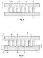
- FIGS. 2-9are cross-sectional views of alternative embodiments of an embedded wire grid polarizer of the present invention.
- FIG. 11is a side view of a pair of glass plates incorporating an embedded wire grid polarizer of the present invention.
- the polarizer 10includes a first optical medium, material, layer or substrate 1 ; a second optical medium, material or layer 3 ; and a plurality of intervening elongated elements 5 sandwiched between the first and second layers 1 and 3 .
- the polarizer 10 of the present inventionis designed to optimize the performance when imbedded, as discussed below.
- the first and second layers 1 and 3have respective first and second surfaces 2 and 4 which face one another and the elements 5 .
- the layers 1 and 3or material of the layers, also have respective first and second refractive indices.
- the first and second optical mediums 1 and 3each have a thickness t L1 and t L2 , and are considered to be thick in an optical sense. They may be, for example, sheets of glass or polymer, an optical quality oil or other fluid, or other similar optical materials.
- the thickness t L1 or t L2may be anywhere from a few microns to essentially infinite in extent. Preferably, the thickness t L1 and t L2 of the layers 1 and 3 is greater than 1 micron.
- the optical media 1 and 3may be the same materials, such as two sheets of glass, or they may be chosen to be different materials, such as an oil for material 3 and glass for material 1 .
- the elements 5may be supported by the first layer or substrate 1 .
- the intervening array of elements 5include a plurality of parallel, elongated, spaced-apart, conductive elements 5 .
- the elements 5have first arid second opposite surfaces 5 a and 5 b , with the first surfaces 5 a facing towards the first surface 2 or first layer 1 , and second surfaces 5 b facing towards the second surface 4 or second layer 3 .
- the first surfaces 5 a of the elements 5may contact and be coupled to the first surface 2 of the first layer 1
- the second surfaces 5 bmay contact and be coupled to the second surface 4 of the second layer 3 , as shown in FIG. 1 .
- the array of elements 5is configured to interact with electromagnetic waves of light in the visible spectrum to generally reflect most of the light of a first polarization, and transmit most of the light of a second polarization.
- the dimensions of the elements 5are determined by the wavelength used, and are tailored for broad or full spectrum visible light.
- the elements 5are relatively long and thin.
- each element 5has a length that is generally larger than the wavelength of visible light.
- the elements 5have a length of at least approximately 0.7 ⁇ m (micrometers or microns). The typical length, however, may be much larger.
- the elements 5are located in generally parallel arrangement with the spacing, pitch, or period P of the elements smaller than the wavelength of light. Thus, the pitch will be less than 0.4 ⁇ m (micrometers or microns).
- the period of the elements 5 , and the choices of the materials for the optical mediums 1 and 3are all made to obtain and enhance the desired interactions with the light rays 9 , 11 and 13 .
- the ray of light 9is typically an unpolarized beam of light containing roughly equal amounts of the two polarizations known in the field as S polarization and P polarization. However, the ray of light 9 may be altered in specific applications to be partially or mostly of either polarization as well.
- the period P of the elements 5is chosen such that the wire grid will specularly reflect most of the light of the S polarized light 11 , and transmit most of the P polarized light 13 .
- the optical materialsalso are chosen to aid in this process.
- the intervening elongated elements 5are not very large. They will typically be arranged in a regular, ordered array having a period P on the order of 0.3 ⁇ m or less, with the width w R of the ribs 5 and the width w S of the spaces or gaps 7 separating the elements on the order of 0.15 ⁇ m or less.
- the width of the elements 5 and the spaces 7can be varied to achieve desired optical performance effects, which will be further described below.
- the height or thickness t R of these elements 5will typically be between that required for the elements to be optically opaque (approximately 40 nm in the case of aluminum) up to a height of perhaps 1 ⁇ m. The upper bound is fixed by considerations of manufacturing practicality as well as optical performance.
- the elements 5are typically composed of materials such as aluminum or silver if the polarizer is to be used across the entire visible spectrum. However, if it is only required in a particular case to provide a polarizer which performs in a portion of the spectrum, such as in red light, then other materials such as copper or gold could be used.
- the gaps 7formed between the elements 5 , advantageously provide a refractive index less than the refractive index of at least one of the layers 1 and 3 , such as the first layer 1 .
- this materialwill be air or vacuum, but for reasons of practicality or performance in certain applications, other materials may be used.
- Other materials which may be usedinclude water (index 1.33), magnesium fluoride (index 1.38) or other common optical thin film materials which can be deposited using evaporation, sputtering, or various chemical vapor deposition processes, optical oils, liquid hydrocarbons such as naptha, toluene, etc. or other materials with suitably low indices.
- a first region 18may be disposed between the first imaginary plane 16 , which extends across the first surfaces 5 a of the elements 5 , and the first surface 2 of the first layer 1 , which includes or provides a lower refractive index than the refractive index of the first layer 1 .
- a second region 19may be disposed between the second imaginary plane 17 , which extends across the second surfaces 5 b of the elements 5 , and the second surface 4 of the second layer 3 , which includes or provides a lower refractive index than the refractive index of the second layer 3 .
- one such improvementis to provide grooves 21 between the elongated elements which extend into the optical media ( 1 and/or 3 ) on one side or the other.
- These grooves 21can be provided during the fabrication method by processes such as reactive ion etching, etc.
- the depth d of the grooves 21is critical to obtaining the proper performance. Depending on the desired optical bandwidth, transmission, extinction, and so on, the depth d of the grooves can be expected to vary from approximately 1 nm to 3000 nm.
- the width w g of the grooves 21will be the same as the space between the elongated elements 5 .
- practical fabrication processes and issuescan be expected to reduce the width somewhat in comparison to the width w S between the elongated elements 5 .
- the inventionalso includes the possibility that future advances in technology will make it practical to fabricate the grooves to a different width than the space 7 between the elongated elements 5 .
- FIG. 3shows an extensior of the concept by adding a top groove 25 in addition to the bottom groove 21 .
- the purpose of the groovesis to create an effective optical index which is reduced in comparison to the optical index of the basic optical material 1 and 3 .
- This reduced optical index in the regions 18 and 19 near the elongated elements 5further enhances the performance of the imbedded wire grid polarizer.
- the grooves in FIG. 2 and FIG. 3are depicted as rectangular, it should not be inferred that this is the only useful or desirable shape. In fact, the manufacturing process is likely to create trapezoidal shapes ( 21 a in FIG. 4) rather than perfect rectangles, and V-shaped grooves ( 21 b in FIG. 5) may be of use as well.
- FIG. 6shows an alternate method of obtaining the advantage of a reduced optical index in the region 19 near the elongated elements 5 by adding a thin film 31 of material with an optical index which is reduced in comparison to the optical material 3 on which it is disposed.
- This filmwill typically have an optical index n lying between 1.0 and 1.7. It will typically have a thickness t L lying between 10 nm and 5000 nm.
- a preferred materialwould be magnesium fluoride, but other common dielectric optical materials may be suitable for various applications. It should not be assumed that a single layer optical film is the only possibility because only a single layer is shown in the drawing. Depending on the application requirements, it may be advantageous to have multiple layers of thin optical films. Also, one or more low index films 35 could be introduced on the bottom as well as the top of the elongated elements 5 , as shown in FIG. 7 .
- FIG. 9shows yet another improvement of the invention in which multiple thin films are prepared and etched either completely or partially.
- the ribs 41 of optical materialare the same as described above.
- the optical film 51is selected to have one or both of the characteristics of: a lower refractive index than the optical material 1 , and the ease with which it can be etched and patterned.
- the groove 55 etched into the optical film 51may be etched all the way through the film, and perhaps even into the underlying optical material 1 , or it may be stopped at an intermediate point, as shown. If the groove 55 is stopped as shown, this has the effect of creating a bi-layer optical thin film stack which may have advantages in tuning the performance of 10 . the polarizer as a whole.
- the thickness t F of the optical film 51will typically lie between approximately 10 nm and 5000 nm.
- the index of the optical material composing the film 51typically will lie between 1.0 and 1.7, though still higher indices may be of value in unusual circumstances.
- the grooves 55 etched in the film 51typically will have a width roughly equal to the space 7 between the elongated elements 5 , though other variations in width are certainly possible and may be preferred depending on the needs of the application. Again, as mentioned earlier, the grooves 55 , though depicted as rectangular, may also be trapezoidal or V-shaped and still provide significant benefit.
- the films or grooves which may be disposed between the elements 5 and the first and/or second layers 1 and 3also provide optical thin film effects which can be used to still further enhance the performance of the polarizer 10 .
- This enhancementcan be obtained by properly adjusting the thickness and/or the number and/or the optical properties of these films or grooves to arrive at the desired over-all performance of the polarizer 10 .
- the imbedded wire grid polarizercan be used in a polarizing beam splitter cube 100 .
- This cubewould function in a manner similar to the common MacNeille prism, but with certain advantages.
- the wire grid polarizerpossesses a wider angular aperture than the MacNeille prism, and also has a much improved performance in the corners of the aperture where the rays in a cone of light incident on the polarizing interface 61 in the middle of the cube are best described with compound angles.
- the polarizing interface 61 containing the imbedded wire grid polarizerreflects most of the S polarized light 65 , while transmitting most of the P polarized light 67 from a beam of light 63 .
- This interface 61may contain any or all of the improvements described above. In this manner, the imbedded wire grid polarizer creates an alternate polarizing cube beam splitter with several performance advantages over the MacNeille polarizing cube beam splitter.
- the imbedded polarizermay also be used in a flat plate format 110 , such as is shown in FIG. 11 .
- This embodimenttypically would consist of glass plates 79 and 81 as shown, which surround the polarizing interface 71 containing the imbedded wire grid polarizer.
- This interface 71may contain any or all of the improvements described above.
- the polarizerserves to polarize a beam of light incident on the first plate 79 by reflecting back at the specular angle a beam of light 75 having the opposite polarization. These light beams 73 , 75 , and 77 are shown as being at normal incidence only for convenience.
- the imbedded wire grid polarizerhas a large angular aperture and will function with light beams coming at a variety of angles.
- a wide bandwidth wire grid polarizeris described in applicants' U.S. patent application Ser. No. 09/337,970, which is herein incorporated by reference.
- Such a polarizeralso includes an array of parallel, conductive elements separated from a supporting substrate by a region with a low refractive index and a controlled thickness.
- the low index region separating the wire grid from the substrateserves two purposes in the polarizer device. First, the presence of the low refractive index shifts the longest wavelength resonance point to a shorter wavelength. Second, the low index region can be implemented as one or more layers of controlled thickness designed to reduce the fraction of P polarized light that is reflected from the polarizer.
- the pitch Ppreferably will be approximately one-half the wavelength of light, or approximately 0.2 ⁇ m.
- grids with longer periodsgreater than approximately twice the wavelength of light or 1.4 ⁇ m
- grids with shorter periodsless than approximately half the wavelength of light or 0.2 ⁇ m
- grids with periods in the transition regionbetween approximately 0.2 and 1.4 ⁇ m
- the grooves, ribs, or film layershave a height or thickness and define the region disposed between the elements and the layers.
- the region created by the grooves, ribs or film layersadvantageously have average indices of refraction which are significantly less than the index of refraction of the layers.
- the regionhas a thickness, which is defined by the height or thickness of the ribs, depth of the grooves, or thickness of the film. The height or thickness of the region may be altered to adjust the performance of the polarizer.
- the array of elements 5is not drawn to scale and has been greatly exaggerated for clarity. In fact, the arrangement of elements is imperceptible to the naked eye and appears as a partially mirrored surface when observed without extreme magnification.
Landscapes
- Physics & Mathematics (AREA)
- General Physics & Mathematics (AREA)
- Optics & Photonics (AREA)
- Polarising Elements (AREA)
Abstract
Description
This application is a continuation-in-part of U.S. patent application Ser. No. 09/337,970, filed Jun. 22, 1999 now U.S. Pat. No. 6,122,103.
1. Field of the Invention
The present invention relates to polarizing optical elements for use in the visible portion of the electromagnetic spectrum. More particularly, the present invention relates to imbedded or immersed wire grid polarizers that efficiently transmit light of a specific polarization while efficiently reflecting light of the orthogonal polarization.
2. Prior Art
Because wire grid polarizers are wavelength sensitive optical devices, imbedding the polarizer in a material or medium with an index of refraction greater than one will always change the performance of the polarizer over that available in air for the same structure. Typically, this change renders the polarizer unsuitable for the intended application. Imbedding the polarizer, however, provides other optical advantages. For example, imbedding the polarizer may provide other beneficial optical properties, and may protect the polarizer, although the performance of the polarizer itself, or polarization, may be detrimentally effected. Therefore, it is desirable to obtain the optimum performance of such an imbedded wire-grid polarizer.
Wire grids are typically disposed on an outer surface of a substrate, such as glass. Some wire grids have been totally encased in the substrate material, or glass. For example, U.S. Pat. No. 2,224,214, issued Dec. 10, 1940, to Brown, discloses forming a polarizer by melting a powdered glass packed around wires, and then stretching the glass and wires. Similarly, U.S. Pat. No. 4,289,381, issued Sep. 15, 1981, to Garvin et al., discloses forming a polarizer by depositing a layer of metallization on a substrate to form the grid, and then depositing substrate material over the grid. In either case, the wires or grid are surrounded by the same material as the substrate. As stated above, such encasement of the wires or grids detrimentally effects the optical performance of the grid.
U.S. Pat. No. 5,748,368, issued May 5, 1998, to Tamada et al., discloses a narrow bandwidth polarizer with a grid disposed on a substrate, and a wedge glass plate disposed over the grid. A matching oil is also applied over the elements which is matched to have the same refractive index as the substrate. Thus, the grid is essentially encased in the substrate or glass because the matching oil has the same refractive index. Again, such encasement of the grid detrimentally effects the optical performance of the gird.
The use of an array of parallel conducting wires to polarize radio waves dates back more than 110 years. Wire grids, generally in the form of an array of thin parallel conductors supported by a transparent substrate, have also been used as polarizers for the infrared portion of the electromagnetic spectrum.
As described in Applicants' prior application, the key factor that determines the performance of a wire grid polarizer is the relationship between the center-to-center spacing, or period, of the parallel grid elements and the wavelength of the incident radiation. If the grid spacing or period is long compared to the wavelength, the grid functions as a diffraction grating, rather than as a polarizer, and diffracts both polarizations (not necessarily with equal efficiency) according to well-known principles. When the grid spacing or period is much shorter than the wavelength, the grid functions as a polarizer that reflects electromagnetic radiation polarized parallel to the grid elements, and transmits radiation of the orthogonal polarization.
The transition region, where the grid period is in the range of roughly one-half of the wavelength to twice the wavelength, is characterized by abrupt changes in the transmission and reflection characteristics of the grid. In particular, an abrupt increase in reflectivity, and corresponding decrease in transmission, for light polarized orthogonal to the grid elements will occur at one or more specific wavelengths at any given angle of incidence. These effects were first reported by Wood in 1902 (Philosophical Magazine, September 1902), and are often referred to as “Wood's Anomalies”. Subsequently, Rayleigh analyzed Wood's data and had the insight that the anomalies occur at combinations of wavelength and angle where a higher diffraction order emerges (Philosophical Magazine, vol. 14(79), pp. 60-65, July 1907). Rayleigh developed an equation to predict the location of the anomalies (which are also commonly referred to in the literature as “Rayleigh Resonances”).
The effect of the angular dependence is to shift the transmission region to larger wavelengths as the angle increases. This is important when the polarizer is intended for use as a polarizing beam splitter or polarizing turning mirror.
A wire grid polarizer is comprised of a multiplicity of parallel conductive electrodes supported by a substrate. Such a device is characterized by the pitch or period of the conductors; the width of the individual conductors; and the thickness of the conductors. A beam of light produced by a light source is incident on the polarizer at an angle Θ from normal, with the plane of incidence orthogonal to the conductive elements. The wire grid polarizer divides this beam into a specularly reflected component, and a non-diffracted, transmitted component. For wavelengths shorter than the longest resonance wavelength, there will also be at least one higher-order diffracted component. Using the normal definitions for S and P polarization, the light with S polarization has the polarization vector orthogonal to the plane of incidence, and thus parallel to the conductive elements. Conversely, light with P polarization has the polarization vector parallel to the plane of incidence and thus orthogonal to the conductive elements.
In general, a wire grid polarizer will reflect light with its electric field vector parallel to the wires of the grid, and transmit light with its electric field vector perpendicular to the wires of the grid, but the plane of incidence may or may not be perpendicular to the wires of the grid as discussed here.
Ideally, the wire grid polarizer will function as a perfect mirror for one polarization of light, such as the S polarized light, and will be perfectly transparent for the other polarization, such as the P polarized light. In practice, however, even the most reflective metals used as mirrors absorb some fraction of the incident light and reflect only 90% to 95%, and plain glass does not transmit 100% of the incident light due to surface reflections.
Applicants' prior application shows transmission and reflection of a wire grid polarizer with two resonances which only affect significantly the polarizer characteristics for P polarization. For incident light polarized in the S direction, the performance of the polarizer approaches the ideal. The reflection efficiency for S polarization is greater than 90% over the visible spectrum from 0.4 μm to 0.7 μm. Over this wavelength band, less than 2.5% of the S polarized light is transmitted, with the balance being absorbed. Except for the small transmitted component, the characteristics of the wire grid polarizer for S polarization are very similar to those of a continuous aluminum mirror.
For P polarization, the transmission and reflection efficiencies of the wire grid are dominated by the resonance effect at wavelengths below about 0.5 μm. At wavelengths longer than 0.5 μm, the wire grid structure acts as a lossy dielectric layer for P polarized light. The losses in this layer and the reflections from the surfaces combine to limit the transmission for P polarized light.
Applicants' prior application also shows the calculated performance of a different type of prior-art wire gird polarizer, as described by Tamada in U.S Pat. No. 5,748,368. As stated above, an index matching fluid has been used between two substrates such that the grid is surrounded by a medium of constant refractive index. This wire grid structure exhibits a single resonance at a wavelength about 0.52 μm. There is a narrow wavelength region, from about 0.58 to 0.62 μm, where the reflectivity for P polarization is very nearly zero. U.S Pat. No. 5,748,368 describes a wire grid polarizer that takes advantage of this effect to implement a narrow bandwidth wire gird polarizer with high extinction ratio. The examples given in the Tamada patent specification used a grid period of 550 nm, and produced a resonance wavelength from 800 to 950 nm depending on the grid thickness, conductor width and shape, and the angle of incidence. The resonance effect that Tamada exploits is different from the resonance whose position is described above. While the two resonances may be coincident, they do not have to be. Tamada exploits this second resonance. Furthermore, there are thin film interference effects which may come into play. The bandwidth of the polarizer, where the reflectivity for the orthogonal-polarized light is less than a few percent, is typically 5% of the center wavelength. While this type of narrow band polarizer may have some applications, many visible-light systems, such as liquid crystal displays, require polarizing optical elements with uniform characteristics over the visible-spectrum wavelengths from 400 nm to 700 nm.
As described in Applicants' prior application, a necessary requirement for a wide band polarizer is that the longest wavelength resonance point must either be suppressed or shifted to a wavelength shorter than the intended spectrum of use. The wavelength of the longest-wavelength resonance point can be reduced in three ways. First, the grid period can be reduced. However, reducing the grid period increases the difficulty of fabricating the grid structure, particularly since the thickness of the grid elements must be maintained to ensure adequate reflectivity of the reflected polarization. Second, the incidence angle can be constrained to near-normal incidence. However, constraining the incidence angle would greatly reduce the utility of the polarizer device, and preclude its use in applications such as projection liquid crystal displays where a wide angular bandwidth centered on 45 degrees is desired. Third, the refractive index of the substrate could be lowered. However, the only cost-effective substrates available for volume manufacture of a polarizer device are several varieties of thin sheet glass, such as Corning type 1737F or Schott type AF45, all of which have a refractive index which varies between 1.5 and 1.53 over the visible spectrum.
Thus, there exists a need for a wire grid polarizer which performs optimally when imbedded or encased. In addition, there exists a need for such a wire grid polarizer, particularly for use in visible light systems requiring broad wavelength bandwidth. In addition, there is a need for such a polarizer structure in which the longest-wavelength resonance point can be eliminated or shifted to a shorter wavelength.
It is an object of the present invention to provide an embedded wire grid polarizer which can provide high transmission and reflection efficiency over the entire visible spectrum.
It is another object of the present invention to provide such an embedded wire grid polarizer which can provide such high efficiency when used over a wide range of incidence angles.
These and other objects and advantages of the present invention are realized in an embedded wire grid polarizer comprising an array of parallel, elongated, spaced-apart elements sandwiched between first and second layers. The elements form a plurality of gaps between the elements, and the gaps provide a refractive index less than the refractive index of the first or second layer. Preferably, the gaps include air or have a vacuum.
The array of elements is configured to interact with electromagnetic waves of light in the visible spectrum to generally reflect most the light of a first polarization, and transmit most the light of a second polarization. The elements preferably have a period less than 0.3 microns, and widths less than 0.15 microns.
In accordance with one aspect of the present invention, the polarizer advantageously has regions between the elements and the first and/or second layer which provide refractive indices which are less than the refractive index of the layers. A plurality of grooves may be formed in the first and/or second layers between the elements which provide the lower refractive indices. Films may be disposed between the first and/or second layer and the elements, which have refractive indices less than the refractive index of the layers.
In accordance with another aspect of the present invention, the films or grooves which may be disposed between the elements and the first and/or second layers provide optical thin film effects which can be used to still further enhance the performance of the polarizer. This enhancement can be obtained by properly adjusting the thickness and/or the number and/or the optical properties of these films or grooves to arrive at the desired over-all performance of the polarizer.
In accordance with another aspect of the present invention, the elements may be disposed in a cube, and oriented diagonally to at least one of the cube surfaces. Alternatively, the elements may be disposed between, and oriented parallel with respect to, a pair of transparent plates.
In accordance with another aspect of the present invention, the array may have a configuration, and the elements may have a size, which would normally create a resonance effect in combination with one or both of the layers within the visible spectrum. The gaps, and/or films and/or grooves, with a lower refractive index than the refractive index of one or both of the layers advantageously causes a shift of the normally occurring resonance effect to a lower wavelength. Thus, a band of visible wavelengths in which no resonance effect occurs is broadened.
These and other objects, features, advantages and alternative aspects of the present invention will become apparent to those skilled in the art from a consideration of the following detailed description taken in combination with the accompanying drawings.
FIG. 1 is a cross-sectional view of a preferred embodiment of an embedded wire grid polarizer of the present invention.
FIGS. 2-9 are cross-sectional views of alternative embodiments of an embedded wire grid polarizer of the present invention.
FIG. 10 is a side view of a cube incorporating an embedded wire grid polarizer of the present invention.
FIG. 11 is a side view of a pair of glass plates incorporating an embedded wire grid polarizer of the present invention.
Reference will now be made to the drawings in which the various elements of the present invention will be given numerical designations and in which the invention will be discussed so as to enable one skilled in the art to make and use the invention.
As illustrated in FIG. 1, a preferred embodiment of an embedded wire grid polarizer of the present invention is shown, indicated generally at10. Thepolarizer 10 includes a first optical medium, material, layer orsubstrate 1; a second optical medium, material orlayer 3; and a plurality of interveningelongated elements 5 sandwiched between the first andsecond layers polarizer 10 of the present invention is designed to optimize the performance when imbedded, as discussed below.
The first andsecond layers second surfaces elements 5. Thelayers optical mediums layers optical media material 3 and glass formaterial 1. Theelements 5 may be supported by the first layer orsubstrate 1.
The intervening array ofelements 5 include a plurality of parallel, elongated, spaced-apart,conductive elements 5. Theelements 5 have first arid secondopposite surfaces first surfaces 5afacing towards thefirst surface 2 orfirst layer 1, andsecond surfaces 5bfacing towards thesecond surface 4 orsecond layer 3. Thefirst surfaces 5aof theelements 5 may contact and be coupled to thefirst surface 2 of thefirst layer 1, while thesecond surfaces 5bmay contact and be coupled to thesecond surface 4 of thesecond layer 3, as shown in FIG.1. The array ofelements 5 is configured to interact with electromagnetic waves of light in the visible spectrum to generally reflect most of the light of a first polarization, and transmit most of the light of a second polarization.
The dimensions of theelements 5, and the dimensions of the arrangement ofelements 5, are determined by the wavelength used, and are tailored for broad or full spectrum visible light. Theelements 5 are relatively long and thin. Preferably, eachelement 5 has a length that is generally larger than the wavelength of visible light. Thus, theelements 5 have a length of at least approximately 0.7 μm (micrometers or microns). The typical length, however, may be much larger. In addition, theelements 5 are located in generally parallel arrangement with the spacing, pitch, or period P of the elements smaller than the wavelength of light. Thus, the pitch will be less than 0.4 μm (micrometers or microns).
The period of theelements 5, and the choices of the materials for theoptical mediums light rays light 9 is typically an unpolarized beam of light containing roughly equal amounts of the two polarizations known in the field as S polarization and P polarization. However, the ray oflight 9 may be altered in specific applications to be partially or mostly of either polarization as well. The period P of theelements 5 is chosen such that the wire grid will specularly reflect most of the light of the S polarized light11, and transmit most of the P polarizedlight 13. The optical materials also are chosen to aid in this process. For example, it is possible to chooseoptical material 1 to be equally transmissive to both S and P polarizations, while choosing anoptical material 3 that would absorb S polarized light or otherwise aid in the transmission of P polarized light and the reflection of S polarized light. In the preferred embodiment, the optical material composing thelayers
The interveningelongated elements 5 are not very large. They will typically be arranged in a regular, ordered array having a period P on the order of 0.3 μm or less, with the width wRof theribs 5 and the width wSof the spaces orgaps 7 separating the elements on the order of 0.15 μm or less. The width of theelements 5 and thespaces 7 can be varied to achieve desired optical performance effects, which will be further described below. The height or thickness tRof theseelements 5 will typically be between that required for the elements to be optically opaque (approximately 40 nm in the case of aluminum) up to a height of perhaps 1 μm. The upper bound is fixed by considerations of manufacturing practicality as well as optical performance. In the preferred embodiment, theelements 5 are typically composed of materials such as aluminum or silver if the polarizer is to be used across the entire visible spectrum. However, if it is only required in a particular case to provide a polarizer which performs in a portion of the spectrum, such as in red light, then other materials such as copper or gold could be used.
An important factor to obtaining the optimum performance of the imbeddedwire grid polarizer 10 is the material disposed within the spaces orgaps 7. Thegaps 7, formed between theelements 5, advantageously provide a refractive index less than the refractive index of at least one of thelayers first layer 1. Applicants have found that, when thegaps 7 provide a lower refractive index, the performance of thepolarizer 10 is improved over wire grids totally encapsulated in a material with a constant refractive index. In the preferred embodiment, this material will be air or vacuum, but for reasons of practicality or performance in certain applications, other materials may be used. It is desirable that this material have the lowest refractive index n possible while meeting other necessary design constraints such as manufacturability. These other constraints may require that the material filling thespaces 7 between theelongated elements 5 be the same material as that composing either or both of theoptical materials spaces 7 between theelongated elements 5 may be chosen to be a material different from theoptical materials spaces 7 will be air or vacuum. Other materials which may be used include water (index 1.33), magnesium fluoride (index 1.38) or other common optical thin film materials which can be deposited using evaporation, sputtering, or various chemical vapor deposition processes, optical oils, liquid hydrocarbons such as naptha, toluene, etc. or other materials with suitably low indices.
In addition to the preferred embodiment described above, there are a number of improvements which may be implemented in particular embodiments for particular purposes. These improvements include providing a region between theelements 5 and the first and/orsecond layers first surfaces 5aof theelements 5 define a firstimaginary plane 16 extending across thefirst surfaces 5a. Similarly, thesecond surfaces 5bof theelements 5 define a secondimaginary plane 17 extending across thesecond surfaces 5b. Afirst region 18 may be disposed between the firstimaginary plane 16, which extends across thefirst surfaces 5aof theelements 5, and thefirst surface 2 of thefirst layer 1, which includes or provides a lower refractive index than the refractive index of thefirst layer 1. Similarly, asecond region 19 may be disposed between the secondimaginary plane 17, which extends across thesecond surfaces 5bof theelements 5, and thesecond surface 4 of thesecond layer 3, which includes or provides a lower refractive index than the refractive index of thesecond layer 3.
Turning now to FIG. 2, one such improvement is to providegrooves 21 between the elongated elements which extend into the optical media (1 and/or3) on one side or the other. Thesegrooves 21 can be provided during the fabrication method by processes such as reactive ion etching, etc. The depth d of thegrooves 21 is critical to obtaining the proper performance. Depending on the desired optical bandwidth, transmission, extinction, and so on, the depth d of the grooves can be expected to vary from approximately 1 nm to 3000 nm.
Typically, the width wgof thegrooves 21 will be the same as the space between theelongated elements 5. However, practical fabrication processes and issues can be expected to reduce the width somewhat in comparison to the width wSbetween theelongated elements 5. The invention also includes the possibility that future advances in technology will make it practical to fabricate the grooves to a different width than thespace 7 between theelongated elements 5. FIG. 3 shows an extensior of the concept by adding atop groove 25 in addition to thebottom groove 21. The purpose of the grooves is to create an effective optical index which is reduced in comparison to the optical index of the basicoptical material regions elongated elements 5 further enhances the performance of the imbedded wire grid polarizer. Even though the grooves in FIG.2 and FIG. 3 are depicted as rectangular, it should not be inferred that this is the only useful or desirable shape. In fact, the manufacturing process is likely to create trapezoidal shapes (21ain FIG. 4) rather than perfect rectangles, and V-shaped grooves (21bin FIG. 5) may be of use as well.
FIG. 6 shows an alternate method of obtaining the advantage of a reduced optical index in theregion 19 near theelongated elements 5 by adding athin film 31 of material with an optical index which is reduced in comparison to theoptical material 3 on which it is disposed. This film will typically have an optical index n lying between 1.0 and 1.7. It will typically have a thickness tLlying between 10 nm and 5000 nm. A preferred material would be magnesium fluoride, but other common dielectric optical materials may be suitable for various applications. It should not be assumed that a single layer optical film is the only possibility because only a single layer is shown in the drawing. Depending on the application requirements, it may be advantageous to have multiple layers of thin optical films. Also, one or morelow index films 35 could be introduced on the bottom as well as the top of theelongated elements 5, as shown in FIG.7.
FIG. 8 shows still another improvement of the invention in which a thin film of material has been etched in a combination of the concepts shown in FIG.2 and FIG.6. The remainingribs 41 of optical material are composed of a material which may have an optical index which is reduced in comparison to theoptical material 3 on which it is disposed. An alternative preference may be for material which does not have an index which is significantly reduced in comparison to the supportingoptical material 3, but which has other properties which aid in the manufacture, such as being easy to etch. One preferred material for theribs 41 would be magnesium fluoride. Other preferred materials may be a polymer material, or silicon dioxide, both of which are easily etched using many techniques. Again, the ribs etched in film may be formed on either layer on either side of the elements.
FIG. 9 shows yet another improvement of the invention in which multiple thin films are prepared and etched either completely or partially. Theribs 41 of optical material are the same as described above. Theoptical film 51 is selected to have one or both of the characteristics of: a lower refractive index than theoptical material 1, and the ease with which it can be etched and patterned. Thegroove 55 etched into theoptical film 51 may be etched all the way through the film, and perhaps even into the underlyingoptical material 1, or it may be stopped at an intermediate point, as shown. If thegroove 55 is stopped as shown, this has the effect of creating a bi-layer optical thin film stack which may have advantages in tuning the performance of10. the polarizer as a whole. The thickness tFof theoptical film 51 will typically lie between approximately 10 nm and 5000 nm. The index of the optical material composing thefilm 51 typically will lie between 1.0 and 1.7, though still higher indices may be of value in unusual circumstances. Thegrooves 55 etched in thefilm 51 typically will have a width roughly equal to thespace 7 between theelongated elements 5, though other variations in width are certainly possible and may be preferred depending on the needs of the application. Again, as mentioned earlier, thegrooves 55, though depicted as rectangular, may also be trapezoidal or V-shaped and still provide significant benefit.
In addition, the films or grooves which may be disposed between theelements 5 and the first and/orsecond layers polarizer 10. This enhancement can be obtained by properly adjusting the thickness and/or the number and/or the optical properties of these films or grooves to arrive at the desired over-all performance of thepolarizer 10.
The above invention can be used in many optical applications. For example, as shown in FIG. 10, the imbedded wire grid polarizer can be used in a polarizingbeam splitter cube 100. This cube would function in a manner similar to the common MacNeille prism, but with certain advantages. The wire grid polarizer possesses a wider angular aperture than the MacNeille prism, and also has a much improved performance in the corners of the aperture where the rays in a cone of light incident on thepolarizing interface 61 in the middle of the cube are best described with compound angles. Thepolarizing interface 61 containing the imbedded wire grid polarizer reflects most of the S polarized light65, while transmitting most of the P polarized light67 from a beam oflight 63. Thisinterface 61 may contain any or all of the improvements described above. In this manner, the imbedded wire grid polarizer creates an alternate polarizing cube beam splitter with several performance advantages over the MacNeille polarizing cube beam splitter.
The imbedded polarizer may also be used in aflat plate format 110, such as is shown in FIG.11. This embodiment typically would consist ofglass plates polarizing interface 71 containing the imbedded wire grid polarizer. Thisinterface 71 may contain any or all of the improvements described above. The polarizer serves to polarize a beam of light incident on thefirst plate 79 by reflecting back at the specular angle a beam of light75 having the opposite polarization. These light beams73,75, and77 are shown as being at normal incidence only for convenience. Again, the imbedded wire grid polarizer has a large angular aperture and will function with light beams coming at a variety of angles.
A wide bandwidth wire grid polarizer is described in applicants' U.S. patent application Ser. No. 09/337,970, which is herein incorporated by reference. Such a polarizer also includes an array of parallel, conductive elements separated from a supporting substrate by a region with a low refractive index and a controlled thickness. The low index region separating the wire grid from the substrate serves two purposes in the polarizer device. First, the presence of the low refractive index shifts the longest wavelength resonance point to a shorter wavelength. Second, the low index region can be implemented as one or more layers of controlled thickness designed to reduce the fraction of P polarized light that is reflected from the polarizer.
One way of reducing the longest wavelength at which resonance occurs for a given angle of incidence, is to reduce the period. But reducing the period creates manufacturing difficulties. Thus, the pitch P preferably will be approximately one-half the wavelength of light, or approximately 0.2 μm. Again, it will be noted that grids with longer periods (greater than approximately twice the wavelength of light or 1.4 μm) operate as diffraction gratings; grids with shorter periods (less than approximately half the wavelength of light or 0.2 μm) operate as a polarizer; and grids with periods in the transition region (between approximately 0.2 and 1.4 μm) also act as diffraction gratings and are characterized by abrupt changes or anomalies referred to as resonances. As indicated above, prior art devices characterized by resonances within the visible spectrum have narrow operating ranges due to the anomalies which occur at various wavelengths within the visible spectrum. This transition region is an important concept in understanding the behavior of the wire grid. Wide bandwidth polarizers must necessarily be designed to stay outside this transition region in order to obtain wide bandwidth performance over the spectrum of intended use. Therefore, the bounds of this transition region are useful in defining the upper limits on the period of the wire grid of the present invention.
The grooves, ribs, or film layers have a height or thickness and define the region disposed between the elements and the layers. The region created by the grooves, ribs or film layers advantageously have average indices of refraction which are significantly less than the index of refraction of the layers. The region has a thickness, which is defined by the height or thickness of the ribs, depth of the grooves, or thickness of the film. The height or thickness of the region may be altered to adjust the performance of the polarizer. Separating the elements from the layers, and interposing a region having a lower refractive index than that of the layers, advantageously increases the p-polarization transmission efficiency of the polarizer at shorter wavelengths, lowers the minimum wavelength at which the polarizer is useful, or shifts the highest resonance point to a shorter wavelength, as discussed more fully in applicants' prior application.
It is noted that the array ofelements 5 is not drawn to scale and has been greatly exaggerated for clarity. In fact, the arrangement of elements is imperceptible to the naked eye and appears as a partially mirrored surface when observed without extreme magnification.
It is to be understood that the described embodiments of the invention are illustrative only, and that modifications thereof may occur to those skilled in the art. In addition, while a primary benefit of the invention is to improve the performance of an imbedded polarizer in the visible spectrum, the invention may also be used to improve the transmission of polarizer devices for use in other regions of the spectrum, such as the infrared. Other alterations will surely occur to those skilled in the art given the significant increase in design flexibility over the prior art that is achieved by the present invention. Accordingly, this invention is not to be regarded as limited to the embodiments disclosed, but is to be limited only as defined by the appended claims herein.
Claims (69)
1. An embedded wire grid polarizer for the visible spectrum, the polarizer comprising:
a first layer having a refractive index;
a second layer, separate from the first layer, having a refractive index; and
an array of parallel, elongated, spaced-apart elements, sandwiched between the first and second layers, and forming a plurality of gaps between the elements, the gaps providing a refractive index less than the refractive index of the first layer.
2. The polarizer of claim1, wherein the gaps between the elements include air.
3. The polarizer of claim1, wherein the gaps between the elements have a vacuum.
4. The polarizer of claim1, wherein gaps between the elements include a material different from materials of the first and second layers.
5. The polarizer of claim1, wherein the gaps between the elements includes a material the same as a material of one of the first and second layers.
6. The polarizer of claim1, wherein the gaps between the elements include water.
7. The polarizer of claim1, wherein the gaps between the elements include magnesium fluoride.
8. The polarizer of claim1, wherein the gaps between the elements include oil.
9. The polarizer of claim1, wherein the gaps between the elements include hydrocarbon.
10. The polarizer of claim1, wherein the first and second layers each have a thickness greater than 1 micron; and wherein the elements have a thickness between 0.04 to 1 microns.
11. The polarizer of claim1, wherein the elements have a period less than 0.3 microns; wherein the elements have widths less than 0.15 microns; and wherein the gaps have widths less than 0.15 microns.
12. The polarizer of claim1, wherein the first layer further has a first surface facing the elements, and the elements further have first surfaces facing the first layer and defining an imaginary plane extending across the first surfaces of the elements; and further comprising:
a region, between the imaginary plane and the first surface of the first layer, providing a refractive index which is less than the refractive index of the first layer.
13. The polarizer of claim1, wherein the first layer has a first surface, and wherein the elements are disposed on the first surface of the first layer; and further comprising:
a plurality of grooves formed in the first surface of the first layer between the elements.
14. The polarizer of claim13, wherein the grooves have a depth between approximately 0.001 to 3 microns.
15. The polarizer of claim1, wherein the first and second layers have respective first and second surfaces between which the elements are disposed; and further comprising:
a first plurality of grooves formed in the first surface of the first layer between the elements; and
a second plurality of grooves formed in the second surface of the second layer between the elements.
16. The polarizer of claim1, further comprising:
a film, disposed between the first layer and the elements, having a refractive index which is less than the refractive index of the first layer.
17. The polarizer of claim16, wherein the refractive index of the film is between approximately 1 and 1.7.
18. The polarizer of claim16, wherein the film has a thickness between approximately 0.01 and 5 microns.
19. The polarizer of claim16, wherein the film includes a dielectric material.
20. The polarizer of claim19, wherein the dielectric material of the film includes magnesium fluoride.
21. The polarizer of claim1, further comprising:
a first film, disposed between the first layer and the elements, having a refractive index which is less than the refractive index of the first layer; and
a second film, disposed between the second layer and the elements, having a refractive index which is less than the refractive index of the second layer.
22. The polarizer of claim1, further comprising:
an array of parallel, elongated, spaced-apart ribs, extending from the first layer towards the elements and oriented parallel with the elements with one rib extending towards each element.
23. The polarizer of claim22, wherein the array of ribs provides a refractive index less than the refractive index of the first layer.
24. The polarizer of claim22, wherein the ribs include magnesium fluoride.
25. The polarizer of claim22, wherein the ribs include silicon dioxide.
26. The polarizer of claim1, further comprising:
a film, disposed between the first layer and the elements; and
a plurality of grooves, formed in the film between the elements.
27. The polarizer of claim26, wherein the film has a refractive index less than the refractive index of the first layer.
28. The polarizer of claim26, wherein the film has a refractive index between approximately 1 and 1.7.
29. The polarizer of claim26, wherein the film has a thickness between approximately 0.01 and 5 microns.
30. The polarizer of claim1, wherein the elements are disposed in a cube, and oriented diagonal to at least one cube surface.
31. The polarizer of claim1, wherein the elements are disposed between and oriented parallel with respect to a pair of transparent plates.
32. The polarizer of claim1, wherein the array has a configuration and the elements have a size which would normally create a resonance effect in combination with one of the layers within the visible spectrum; and wherein the gaps with a lower refractive index than the refractive index of one of the layers causes a shift of the normally occurring resonance effect to a lower wavelength, thereby broadening a band of visible wavelengths in which no resonance effect occurs.
33. The polarizer of claim1, wherein the array of elements is configured to interact with electromagnetic waves of light in the visible spectrum to generally reflect most the light of a first polarization and transmit most the light of a second polarization.
34. An imbedded wire grid polarizer for the visible spectrum, the polarizer comprising:
first and second separate layers having respective first and second surfaces facing towards one another, and respective first and second refractive indices;
an array of parallel, elongated, spaced-apart elements, sandwiched between the first and second surfaces of the first and second layers, the elements having first surfaces facing towards the first surface of the first layer and defining an imaginary plane extending across the first surfaces of the elements; and
a region, between the imaginary plane extending across the first surfaces of the elements and the first surface of the first layer, having a refractive index which is less than the refractive index of the first layer.
35. The polarizer of claim34, wherein the region includes a plurality of grooves formed in the first surface of the first layer between the elements.
36. The polarizer of claim35, wherein the grooves have a depth between approximately 0.001 to 3 microns.
37. The polarizer of claim34, wherein the elements further have second surfaces facing the second surface of the second layer and defining a second imaginary plane extending across the second surfaces of the elements; and further comprising:
a second region, between the second imaginary plane extending across the second surfaces of the elements and the second surface of the second layer, having a refractive index which is less than the refractive index of the second layer.
38. The polarizer of claim37, wherein the regions include:
a first plurality of grooves formed in the first surface of the first layer between the elements; and
a second plurality of grooves formed in the second surface of the second layer between the elements.
39. The polarizer of claim34, wherein the region includes:
a film, disposed between the first layer and the elements, having a refractive index which is less than the refractive index of the first layer.
40. The polarizer of claim39, wherein the refractive index of the film is between approximately 1 and 1.7.
41. The polarizer of claim39, wherein the film has a thickness between approximately 0.01 and 5 microns.
42. The polarizer of claim39, wherein the film includes a dielectric material.
43. The polarizer of claim42, wherein the film includes magnesium fluoride.
44. The polarizer of claim37, wherein the regions include:
a first film, disposed between the first layer and the elements, having a refractive index which is less than the refractive index of the first layer; and
a second film, disposed between the second layer and the elements, having a refractive index which is less than the refractive index of the second layer.
45. The polarizer of claim34, wherein the region includes:
an array of parallel, elongated, spaced-apart ribs, extending from the first layer towards the elements.
46. The polarizer of claim45, wherein the ribs include magnesium fluoride.
47. The polarizer of claim45, wherein the ribs include silicon dioxide.
48. The polarizer of claim34, wherein the region includes:
a film, disposed between the first layer and the elements; and
a plurality of grooves, formed in the film between the elements.
49. The polarizer of claim48, wherein the film has a refractive index between approximately 1 and 1.7.
50. The polarizer of claim48, wherein the film has a thickness between approximately 0.01 and 5 microns.
51. The polarizer of claim34, wherein the array of elements forms a plurality of gaps between the elements, the gaps providing a refractive index less than the refractive index of one of the layers.
52. The polarizer of claim51, wherein the gaps between the elements include air.
53. The polarizer of claim51, wherein the gaps between the elements have a vacuum.
54. The polarizer of claim51, wherein the gaps between the elements include a material different from materials of the first and second layers.
55. The polarizer of claim51, wherein the gaps between the elements include a material the same as a material of one of the first and second layers.
56. The polarizer of claim51, wherein the gaps between the elements include water.
57. The polarizer of claim51, wherein the gaps between the elements include magnesium fluoride.
58. The polarizer of claim51, wherein the gaps between the elements include oil.
59. The polarizer of claim51, wherein the gaps between the elements include hydrocarbon.
60. The polarizer of claim51, wherein the array has a configuration and the elements have a size which would normally create a resonance effect in combination with one of the layers within the visible spectrum; and wherein the gaps with a lower refractive index than the refractive index of one of the layers causes a shift of the normally occurring resonance effect to a lower wavelength, thereby broadening a band of visible wavelengths in which no resonance effect occurs.
61. The polarizer of claim34, wherein the first and second layers each have a thickness greater than 1 micron; and wherein the elements have a thickness between 0.04 to 1 microns.
62. The polarizer of claim34, wherein the elements have a period less than 0.3 microns; wherein the elements have a width less than 0.15 microns; and wherein the elements are separated by spaces with widths less than 0.15 microns.
63. The polarizer of claim34, wherein the elements are disposed in a cube, and oriented diagonal to at least one cube surface.
64. The polarizer of claim34, wherein the elements are disposed between and oriented parallel with respect to a pair of transparent plates.
65. The polarizer of claim34, wherein the array of elements is configured to interact with electromagnetic waves of light in the visible spectrum to generally reflect most the light of a first polarization and transmit most the light of a second polarization.
66. An embedded wire grid polarizer for the visible spectrum, the polarizer comprising:
a substrate having a first surface and a first refractive index;
an array of parallel, elongated, spaced-apart elements, coupled to and oriented parallel to the substrate, configured to interact with electromagnetic waves of light in the visible spectrum to generally reflect most the light of a first polarization and transmit most the light of a second polarization, and forming a plurality of gaps between the elements, the gaps providing a refractive index less than the first refractive index of the substrate; and
a layer, coupled to and oriented parallel to the array of elements, having a second refractive index.
67. The device of claim66, wherein the array has a configuration and the elements have a size which would normally create a resonance effect in combination with the substrate within the visible spectrum; and wherein the gaps with a lower refractive index than the first refractive index of the substrate causes a shift of the normally occurring resonance effect to a lower wavelength, thereby broadening a band of visible wavelengths in which no resonance effect occurs.
68. The device of claim66, wherein the elements further have first surfaces facing the first surface of the substrate and defining an imaginary plane extending across the first surfaces of the elements; and further comprising:
a region, between the imaginary plane extending across the first surfaces of the elements and the first surface of the substrate, the region providing a refractive index which is less than the first refractive index of the substrate.
69. The device of claim66, wherein the elements further have second surfaces facing the second surface of the second layer and defining a second imaginary plane extending across the second surfaces of the elements; and further comprising:
a second region, between the second imaginary plane extending across the second surfaces of the elements and the second surface of the second layer, the region providing a refractive index which is less than the refractive index of the second layer.
Priority Applications (8)
| Application Number | Priority Date | Filing Date | Title |
|---|---|---|---|
| US09/480,393US6288840B1 (en) | 1999-06-22 | 2000-01-11 | Imbedded wire grid polarizer for the visible spectrum |
| PCT/US2001/001012WO2001051964A1 (en) | 2000-01-11 | 2001-01-11 | Imbedded wire grid polarizer for the visible spectrum |
| JP2001552123AJP4688394B2 (en) | 2000-01-11 | 2001-01-11 | Embedded wire grid polarizer for the visible spectrum |
| EP01900993AEP1250614A4 (en) | 2000-01-11 | 2001-01-11 | Imbedded wire grid polarizer for the visible spectrum |
| CNB018036058ACN1222790C (en) | 2000-01-11 | 2001-01-11 | Imbedded wire grid polarizer for visible spectrum |
| KR1020027008879AKR100744863B1 (en) | 2000-01-11 | 2001-01-11 | Insertion Wire Grating Polarizer for Visible Light Band |
| AU2001226391AAU2001226391A1 (en) | 2000-01-11 | 2001-01-11 | Imbedded wire grid polarizer for the visible spectrum |
| JP2010280064AJP4809929B2 (en) | 2000-01-11 | 2010-12-16 | Embedded wire grid polarizer for the visible spectrum |
Applications Claiming Priority (2)
| Application Number | Priority Date | Filing Date | Title |
|---|---|---|---|
| US09/337,970US6122103A (en) | 1999-06-22 | 1999-06-22 | Broadband wire grid polarizer for the visible spectrum |
| US09/480,393US6288840B1 (en) | 1999-06-22 | 2000-01-11 | Imbedded wire grid polarizer for the visible spectrum |
Related Parent Applications (1)
| Application Number | Title | Priority Date | Filing Date |
|---|---|---|---|
| US09/337,970Continuation-In-PartUS6122103A (en) | 1999-06-22 | 1999-06-22 | Broadband wire grid polarizer for the visible spectrum |
Publications (1)
| Publication Number | Publication Date |
|---|---|
| US6288840B1true US6288840B1 (en) | 2001-09-11 |
Family
ID=23907785
Family Applications (1)
| Application Number | Title | Priority Date | Filing Date |
|---|---|---|---|
| US09/480,393Expired - LifetimeUS6288840B1 (en) | 1999-06-22 | 2000-01-11 | Imbedded wire grid polarizer for the visible spectrum |
Country Status (7)
| Country | Link |
|---|---|
| US (1) | US6288840B1 (en) |
| EP (1) | EP1250614A4 (en) |
| JP (2) | JP4688394B2 (en) |
| KR (1) | KR100744863B1 (en) |
| CN (1) | CN1222790C (en) |
| AU (1) | AU2001226391A1 (en) |
| WO (1) | WO2001051964A1 (en) |
Cited By (176)
| Publication number | Priority date | Publication date | Assignee | Title |
|---|---|---|---|---|
| JPH0950551A (en)* | 1995-08-07 | 1997-02-18 | Fujitsu Ltd | Banknote transaction device |
| WO2002077588A3 (en)* | 2001-03-27 | 2002-11-21 | Moxtek | Patterned wire grid polarizer and method of use |
| US20020191287A1 (en)* | 2001-03-29 | 2002-12-19 | Seiko Epson Corporation | Polarizer and optical device using the polarizer |
| US6532111B2 (en)* | 2001-03-05 | 2003-03-11 | Eastman Kodak Company | Wire grid polarizer |
| US20030081317A1 (en)* | 2001-10-01 | 2003-05-01 | Masao Katsumata | Prism, projection device and optical component |
| US6585378B2 (en) | 2001-03-20 | 2003-07-01 | Eastman Kodak Company | Digital cinema projector |
| WO2003069381A3 (en)* | 2002-02-12 | 2003-11-13 | Unaxis Balzers Ltd | Optical component comprising submicron hollow spaces |
| US20030223670A1 (en)* | 2002-05-30 | 2003-12-04 | Anguel Nikolov | Optical polarization beam combiner/splitter |
| US6665119B1 (en) | 2002-10-15 | 2003-12-16 | Eastman Kodak Company | Wire grid polarizer |
| US20040008416A1 (en)* | 2002-07-11 | 2004-01-15 | Canon Kabushiki Kaisha | Polarization separation element and optical apparatus using the same |
| US20040032663A1 (en)* | 2002-08-19 | 2004-02-19 | Tekolste Robert | Wafer level polarization control elements |
| US20040047638A1 (en)* | 2002-06-17 | 2004-03-11 | Jian Wang | Method and system for performing wavelength locking of an optical transmission source |
| US20040047388A1 (en)* | 2002-06-17 | 2004-03-11 | Jian Wang | Optical device and method for making same |
| US6714350B2 (en) | 2001-10-15 | 2004-03-30 | Eastman Kodak Company | Double sided wire grid polarizer |
| US20040071425A1 (en)* | 2002-10-09 | 2004-04-15 | Jian Wang | Monolithic tunable lasers and reflectors |
| US20040071180A1 (en)* | 2002-10-09 | 2004-04-15 | Jian Wang | Freespace tunable optoelectronic device and method |
| US6738127B1 (en)* | 2003-04-24 | 2004-05-18 | Eastman Kodak Company | LCD-based printing apparatus for printing onto high contrast photosensitive medium |
| WO2003054619A3 (en)* | 2001-12-21 | 2004-06-17 | Koninkl Philips Electronics Nv | Sealed enclosure for a wire-grid polarizer and subassembly of a display device |
| US6764181B2 (en)* | 2001-05-18 | 2004-07-20 | 3M Innovative Properties Company | Polarization arrangement |
| US20040179158A1 (en)* | 2002-01-07 | 2004-09-16 | Eastman Kodak Company | Display with a wire grid polarizing beamsplitter |
| US6798487B1 (en)* | 1999-09-27 | 2004-09-28 | Nitto Denko Corporation | Liquid crystal cell substrate including resin substrate, gas barrier layer, crosslinked resin layer and polarizing layer |
| US20040201889A1 (en)* | 2002-08-21 | 2004-10-14 | Jian Wang | Method and system for providing beam polarization |
| US6805445B2 (en) | 2002-06-05 | 2004-10-19 | Eastman Kodak Company | Projection display using a wire grid polarization beamsplitter with compensator |
| US20040207320A1 (en)* | 2003-04-15 | 2004-10-21 | Erchak Alexei A. | Light emitting devices |
| US20040206971A1 (en)* | 2003-04-15 | 2004-10-21 | Erchak Alexei A. | Light emitting devices |
| US20040207319A1 (en)* | 2003-04-15 | 2004-10-21 | Erchak Alexei A. | Light emitting devices |
| US20040207310A1 (en)* | 2003-04-15 | 2004-10-21 | Erchak Alexei A. | Light emitting devices |
| US20040207323A1 (en)* | 2003-04-15 | 2004-10-21 | Erchak Alexei A. | Light emitting devices |
| US20040206962A1 (en)* | 2003-04-15 | 2004-10-21 | Erchak Alexei A. | Light emitting devices |
| US20040218125A1 (en)* | 2002-01-07 | 2004-11-04 | Xiang-Dong Mi | Modulation optical system |
| US20040218270A1 (en)* | 2003-02-10 | 2004-11-04 | Jian Wang | Universal broadband polarizer, devices incorporating same, and method of making same |
| US20040227923A1 (en)* | 2003-02-27 | 2004-11-18 | Flagello Donis George | Stationary and dynamic radial transverse electric polarizer for high numerical aperture systems |
| US20040252478A1 (en)* | 2001-03-23 | 2004-12-16 | Wavien, Inc. | Polarization recovery system using redirection |
| US20040259279A1 (en)* | 2003-04-15 | 2004-12-23 | Erchak Alexei A. | Light emitting device methods |
| US20040259285A1 (en)* | 2003-04-15 | 2004-12-23 | Erchak Alexei A. | Light emitting device methods |
| US20040258355A1 (en)* | 2003-06-17 | 2004-12-23 | Jian Wang | Micro-structure induced birefringent waveguiding devices and methods of making same |
| US20040263989A1 (en)* | 2003-06-25 | 2004-12-30 | Eastman Kodak Company | Display apparatus |
| US20040263806A1 (en)* | 2002-06-05 | 2004-12-30 | Eastman Kodak Company | Housing for mounting a beamsplitter and a spatial light modulator with an output optical path |
| US6847057B1 (en) | 2003-08-01 | 2005-01-25 | Lumileds Lighting U.S., Llc | Semiconductor light emitting devices |
| US6859303B2 (en) | 2002-06-18 | 2005-02-22 | Nanoopto Corporation | Optical components exhibiting enhanced functionality and method of making same |
| US20050040424A1 (en)* | 2003-04-15 | 2005-02-24 | Erchak Alexei A. | Light emitting diode systems |
| US20050051785A1 (en)* | 2003-04-15 | 2005-03-10 | Erchak Alexei A. | Electronic device contact structures |
| US20050059179A1 (en)* | 2003-09-17 | 2005-03-17 | Erchak Alexei A. | Light emitting device processes |
| US20050059178A1 (en)* | 2003-09-17 | 2005-03-17 | Erchak Alexei A. | Light emitting device processes |
| US20050078372A1 (en)* | 2003-09-01 | 2005-04-14 | Kazuhiko Momoki | Polarization beam splitter and optical system using the same, and image displaying apparatus, using the same |
| US20050087754A1 (en)* | 2003-04-15 | 2005-04-28 | Erchak Alexei A. | Light emitting systems |
| US20050087757A1 (en)* | 2003-04-15 | 2005-04-28 | Luminus Devices, Inc., A Delaware Corporation | Light emitting devices |
| WO2004077102A3 (en)* | 2003-02-21 | 2005-05-12 | Wavien Inc | Polarization recovery system using redirection |
| US20050128368A1 (en)* | 2003-12-10 | 2005-06-16 | Katsuhide Aoto | Liquid crystal projector |
| US20050127375A1 (en)* | 2003-12-12 | 2005-06-16 | Erchak Alexei A. | Optical display systems and methods |
| US20050180008A1 (en)* | 2003-02-27 | 2005-08-18 | Asml Netherlands B.V. | Stationary and dynamic radial transverse electric polarizer for high numerical aperture systems |
| US20050213043A1 (en)* | 2004-03-03 | 2005-09-29 | Hitachi, Ltd. | Optical unit and projection-type image display apparatus using the same |
| US20050277063A1 (en)* | 2004-04-15 | 2005-12-15 | Wang Jian J | Optical films and methods of making the same |
| US20050275944A1 (en)* | 2004-06-11 | 2005-12-15 | Wang Jian J | Optical films and methods of making the same |
| US20060001969A1 (en)* | 2004-07-02 | 2006-01-05 | Nanoopto Corporation | Gratings, related optical devices and systems, and methods of making such gratings |
| US20060007700A1 (en)* | 2004-07-06 | 2006-01-12 | Au Optronics Corp. | Backlight module capable of interchanging polarized states of light |
| US20060038188A1 (en)* | 2004-08-20 | 2006-02-23 | Erchak Alexei A | Light emitting diode systems |
| US20060043391A1 (en)* | 2003-04-15 | 2006-03-02 | Erchak Alexei A | Light emitting devices for liquid crystal displays |
| US20060061862A1 (en)* | 2004-09-23 | 2006-03-23 | Eastman Kodak Company | Low fill factor wire grid polarizer and method of use |
| US20060061519A1 (en)* | 2004-09-17 | 2006-03-23 | Fisher Arthur D | Microdisplay |
| US20060087602A1 (en)* | 2004-10-27 | 2006-04-27 | Terufusa Kunisada | Polarizer and method for producing it |
| US7050233B2 (en) | 2002-08-01 | 2006-05-23 | Nanoopto Corporation | Precision phase retardation devices and method of making same |
| US20060113279A1 (en)* | 2004-11-30 | 2006-06-01 | Little Michael J | Non-photolithographic method for forming a wire grid polarizer for optical and infrared wavelengths |
| US20060118514A1 (en)* | 2004-11-30 | 2006-06-08 | Agoura Technologies, Inc. | Applications and fabrication techniques for large scale wire grid polarizers |
| US20060127830A1 (en)* | 2004-12-15 | 2006-06-15 | Xuegong Deng | Structures for polarization and beam control |
| US20060127829A1 (en)* | 2004-12-15 | 2006-06-15 | Xuegong Deng | Structures for polarization and beam control |
| US20060163590A1 (en)* | 2005-01-21 | 2006-07-27 | Erchak Alexei A | Packaging designs for LEDs |
| US7085050B2 (en)* | 2001-12-13 | 2006-08-01 | Sharp Laboratories Of America, Inc. | Polarized light beam splitter assembly including embedded wire grid polarizer |
| US20060177571A1 (en)* | 2005-02-10 | 2006-08-10 | Seiko Epson Corporation | Method for manufacturing optical element |
| US20060181662A1 (en)* | 2003-03-07 | 2006-08-17 | Tadayuki Kameyama | High luminance polarizing plate, and liquid crystal panel and image display using same |
| US20060185983A1 (en)* | 2005-02-21 | 2006-08-24 | Seiko Epson Corporation | Method for manufacturing optical element |
| US20060215263A1 (en)* | 2004-09-23 | 2006-09-28 | Eastman Kodak Company | Wire grid polarizers with optical features |
| US7170100B2 (en) | 2005-01-21 | 2007-01-30 | Luminus Devices, Inc. | Packaging designs for LEDs |
| US20070046872A1 (en)* | 2005-08-30 | 2007-03-01 | Konica Minolta Opto, Inc. | Liquid crystal display |
| US20070047214A1 (en)* | 2005-08-30 | 2007-03-01 | Samsung Electronics Co., Ltd. | Backlight unit using wire-grid polarizer and liquid crystal display apparatus employing the backlight unit |
| US20070045640A1 (en)* | 2005-08-23 | 2007-03-01 | Erchak Alexei A | Light emitting devices for liquid crystal displays |
| US20070139771A1 (en)* | 2005-12-15 | 2007-06-21 | Jian Wang | Optical retarders and methods of making the same |
| US20070165308A1 (en)* | 2005-12-15 | 2007-07-19 | Jian Wang | Optical retarders and methods of making the same |
| US20070217008A1 (en)* | 2006-03-17 | 2007-09-20 | Wang Jian J | Polarizer films and methods of making the same |
| US20070229765A1 (en)* | 2006-03-30 | 2007-10-04 | Infocus Corporation | Projection system and method |
| US20070264581A1 (en)* | 2006-05-09 | 2007-11-15 | Schwarz Christian J | Patterning masks and methods |
| US7306338B2 (en) | 1999-07-28 | 2007-12-11 | Moxtek, Inc | Image projection system with a polarizing beam splitter |
| US20080036945A1 (en)* | 2006-08-11 | 2008-02-14 | Hon Hai Precision Industry Co., Ltd. | Polarizer and liquid crystal display employing same |
| US20080037101A1 (en)* | 2006-08-11 | 2008-02-14 | Eastman Kodak Company | Wire grid polarizer |
| US20080055719A1 (en)* | 2006-08-31 | 2008-03-06 | Perkins Raymond T | Inorganic, Dielectric Grid Polarizer |
| US20080094576A1 (en)* | 2006-10-04 | 2008-04-24 | 3M Innovative Properties Company | Projection system incorporating color correcting element |
| US20080099777A1 (en)* | 2005-10-19 | 2008-05-01 | Luminus Devices, Inc. | Light-emitting devices and related systems |
| WO2008002541A3 (en)* | 2006-06-26 | 2008-05-02 | Moxtek Inc | Cube wire-grid polarizing beam splitter and projection display with same |
| US7375887B2 (en) | 2001-03-27 | 2008-05-20 | Moxtek, Inc. | Method and apparatus for correcting a visible light beam using a wire-grid polarizer |
| US20080119048A1 (en)* | 2006-11-21 | 2008-05-22 | Chandrasekhar Sarma | Lithography masks and methods of manufacture thereof |
| US20080129930A1 (en)* | 2006-12-01 | 2008-06-05 | Agoura Technologies | Reflective polarizer configuration for liquid crystal displays |
| US20080136315A1 (en)* | 2006-10-24 | 2008-06-12 | Joon-Gu Lee | Polarizer and organic light emitting display apparatus including the same |
| US20080137010A1 (en)* | 2006-12-07 | 2008-06-12 | Seiko Epson Corporation | Polarizing element, method for manufacturing the same, liquid crystal device and electronic apparatus |
| US20080143965A1 (en)* | 2006-10-18 | 2008-06-19 | Real D | Combining P and S rays for bright stereoscopic projection |
| US20080210893A1 (en)* | 2007-01-24 | 2008-09-04 | Ravenbrick, Llc | Thermally switched optical downconverting filter |
| US20080225236A1 (en)* | 2006-09-29 | 2008-09-18 | Colorlink, Inc. | Polarization conversion systems for stereoscopic projection |
| US20080274574A1 (en)* | 2007-03-20 | 2008-11-06 | Luminus Devices, Inc. | Laser liftoff structure and related methods |
| US7570424B2 (en) | 2004-12-06 | 2009-08-04 | Moxtek, Inc. | Multilayer wire-grid polarizer |
| US20090219603A1 (en)* | 2007-05-18 | 2009-09-03 | Jiuzhi Xue | Temperature activated optical films |
| US20090284670A1 (en)* | 2005-03-15 | 2009-11-19 | Jiuzhi Xue | Windows with electrically controllable transmission and reflection |
| US7630133B2 (en) | 2004-12-06 | 2009-12-08 | Moxtek, Inc. | Inorganic, dielectric, grid polarizer and non-zero order diffraction grating |
| KR100933443B1 (en)* | 2002-12-31 | 2009-12-24 | 엘지디스플레이 주식회사 | Composite optical element for display device |
| US20100079706A1 (en)* | 2008-09-29 | 2010-04-01 | Samsung Electronics Co., Ltd | Polarizer, method of manufacturing the same, display substrate having the polarizer, and backlight assembly having the polarizer |
| US20100128347A1 (en)* | 2008-11-19 | 2010-05-27 | Herb He Huang | Polarizing cube and method of fabricating the same |
| US20100151510A1 (en)* | 2003-12-16 | 2010-06-17 | Canon Kabushiki Kaisha | Substrate for cell culture, producing method thereof and screening method for cell culture conditions utilizing the same |
| US7755829B2 (en) | 2007-07-11 | 2010-07-13 | Ravenbrick Llc | Thermally switched reflective optical shutter |
| US7789515B2 (en) | 2007-05-17 | 2010-09-07 | Moxtek, Inc. | Projection device with a folded optical path and wire-grid polarizer |
| US7800823B2 (en) | 2004-12-06 | 2010-09-21 | Moxtek, Inc. | Polarization device to polarize and further control light |
| US7961393B2 (en) | 2004-12-06 | 2011-06-14 | Moxtek, Inc. | Selectively absorptive wire-grid polarizer |
| US20110273771A1 (en)* | 2009-01-13 | 2011-11-10 | Canon Kabushiki Kaisha | Optical element |
| US8081273B2 (en) | 2006-10-26 | 2011-12-20 | Samsung Electronics Co., Ltd. | Liquid crystal display |
| US8169685B2 (en) | 2007-12-20 | 2012-05-01 | Ravenbrick, Llc | Thermally switched absorptive window shutter |
| US20120169972A1 (en)* | 2010-12-29 | 2012-07-05 | Samsung Electronics Co., Ltd. | Liquid crystal display panel and apparatus including the same |
| US8248696B2 (en) | 2009-06-25 | 2012-08-21 | Moxtek, Inc. | Nano fractal diffuser |
| US8284336B2 (en) | 2009-04-10 | 2012-10-09 | Ravenbrick Llc | Thermally switched optical filter incorporating a guest-host architecture |
| TWI411820B (en)* | 2006-08-11 | 2013-10-11 | Hon Hai Prec Ind Co Ltd | Polarizer and liquid crystal display using same |
| US8611007B2 (en) | 2010-09-21 | 2013-12-17 | Moxtek, Inc. | Fine pitch wire grid polarizer |
| US8634137B2 (en) | 2008-04-23 | 2014-01-21 | Ravenbrick Llc | Glare management of reflective and thermoreflective surfaces |
| US8643795B2 (en) | 2009-04-10 | 2014-02-04 | Ravenbrick Llc | Thermally switched optical filter incorporating a refractive optical structure |
| JP2014038287A (en)* | 2012-08-20 | 2014-02-27 | Asahi Kasei E-Materials Corp | Optical element and projection type video display device using the same |
| US8665414B2 (en) | 2008-08-20 | 2014-03-04 | Ravenbrick Llc | Methods for fabricating thermochromic filters |
| US8699114B2 (en) | 2010-06-01 | 2014-04-15 | Ravenbrick Llc | Multifunctional building component |
| US8755113B2 (en) | 2006-08-31 | 2014-06-17 | Moxtek, Inc. | Durable, inorganic, absorptive, ultra-violet, grid polarizer |
| US8828176B2 (en) | 2010-03-29 | 2014-09-09 | Ravenbrick Llc | Polymer stabilized thermotropic liquid crystal device |
| US8867132B2 (en) | 2009-10-30 | 2014-10-21 | Ravenbrick Llc | Thermochromic filters and stopband filters for use with same |
| US8873144B2 (en) | 2011-05-17 | 2014-10-28 | Moxtek, Inc. | Wire grid polarizer with multiple functionality sections |
| US8908267B2 (en) | 2007-09-19 | 2014-12-09 | Ravenbrick, Llc | Low-emissivity window films and coatings incorporating nanoscale wire grids |
| US8913321B2 (en) | 2010-09-21 | 2014-12-16 | Moxtek, Inc. | Fine pitch grid polarizer |
| US8913320B2 (en) | 2011-05-17 | 2014-12-16 | Moxtek, Inc. | Wire grid polarizer with bordered sections |
| US8922890B2 (en) | 2012-03-21 | 2014-12-30 | Moxtek, Inc. | Polarizer edge rib modification |
| US8947760B2 (en) | 2009-04-23 | 2015-02-03 | Ravenbrick Llc | Thermotropic optical shutter incorporating coatable polarizers |
| US9116302B2 (en) | 2008-06-19 | 2015-08-25 | Ravenbrick Llc | Optical metapolarizer device |
| US9195093B2 (en) | 2012-10-08 | 2015-11-24 | Samsung Display Co., Ltd. | Polarizer, liquid crystal display, and manufacturing method thereof |
| CN101334497B (en)* | 2007-06-28 | 2015-11-25 | 第一毛织株式会社 | Polarized light splitting device and manufacture method thereof and equipment and comprise its display |
| US9229137B2 (en) | 2013-10-02 | 2016-01-05 | Samsung Display Co., Ltd. | Wire grid polarizer comprising transparent particles, display device including the same, and method of fabricating the wire grid polarizer |
| US9244320B2 (en) | 2012-10-29 | 2016-01-26 | Samsung Display Co., Ltd. | Liquid crystal display and manufacturing method thereof |
| US9329316B2 (en) | 2013-08-27 | 2016-05-03 | Samsung Electronics Co., Ltd. | Wire grid polarizer and liquid crystal display panel and liquid crystal display device having the same |
| US9335582B2 (en) | 2013-05-29 | 2016-05-10 | Samsung Electronics Co., Ltd. | Wire grid polarizer, and liquid crystal display panel and liquid crystal display device including the same |
| US9348076B2 (en) | 2013-10-24 | 2016-05-24 | Moxtek, Inc. | Polarizer with variable inter-wire distance |
| US9423646B2 (en) | 2013-04-18 | 2016-08-23 | Samsung Display Co., Ltd. | Display device |
| US9568767B2 (en) | 2013-09-04 | 2017-02-14 | Samsung Display Co., Ltd. | Display apparatus |
| US9575356B2 (en) | 2014-12-12 | 2017-02-21 | Samsung Display Co., Ltd. | Polarizer, display substrate, display panel having the same and method of manufacturing the same |
| US9625745B2 (en) | 2013-11-15 | 2017-04-18 | Reald Inc. | High dynamic range, high contrast projection systems |
| US9696474B2 (en) | 2014-07-28 | 2017-07-04 | Samsung Display Co., Ltd. | Polarizer and display panel having the same |
| US9726897B2 (en) | 2014-05-28 | 2017-08-08 | Motex, Inc. | Cube polarizer with minimal optical path length difference |
| US9740016B2 (en) | 2007-05-09 | 2017-08-22 | Reald Inc. | Polarization conversion system and method for projecting polarization encoded imagery |
| US9829741B2 (en) | 2013-08-02 | 2017-11-28 | Samsung Display Co., Ltd. | Wire grid polarizer and liquid crystal display device having the same |
| US9885906B2 (en) | 2014-10-22 | 2018-02-06 | Samsung Display Co., Ltd. | Method of manufacturing a polarizer with reduced reflecitivity and a display panel having the same |
| WO2018097893A1 (en)* | 2016-11-22 | 2018-05-31 | Moxtek, Inc. | Embedded wire grid polarizer with high reflectivity on both sides |
| US20180180786A1 (en)* | 2016-12-28 | 2018-06-28 | Dexerials Corporation | Polarizing plate, method of manufacturing the same, and optical apparatus |
| US10067276B2 (en) | 2016-08-25 | 2018-09-04 | Samsung Display Co., Ltd. | Polarizer, method of manufacturing the same, and display device including the same |
| US10078242B2 (en) | 2014-11-11 | 2018-09-18 | Samsung Display Co., Ltd. | Display panel and method of manufacturing a polarizer |
| US10082612B2 (en) | 2014-12-05 | 2018-09-25 | Samsung Display Co., Ltd. | Wire grid polarizer, display device including the same, and method of fabricating the same |
| US10114161B2 (en) | 2010-12-30 | 2018-10-30 | Moxtek, Inc. | Multi-layer absorptive wire grid polarizer |
| DE102004050891B4 (en) | 2004-10-19 | 2019-01-10 | Lumileds Holding B.V. | Light-emitting III-nitride semiconductor device |
| US10234613B2 (en) | 2015-02-06 | 2019-03-19 | Moxtek, Inc. | High contrast inverse polarizer |
| US10261359B1 (en) | 2017-11-13 | 2019-04-16 | Samsung Display Co., Ltd. | Polarizer and display device including the same |
| US10268046B2 (en) | 2014-05-28 | 2019-04-23 | Moxtek, Inc. | Cube polarizer |
| US10330946B1 (en) | 2016-05-04 | 2019-06-25 | Moxtek, Inc. | Symmetric cube polarizing beam splitter |
| US10345636B2 (en) | 2016-08-29 | 2019-07-09 | Samsung Display Co., Ltd. | Polarizer, method of manufacturing the same, and display apparatus having the same |
| US10353127B2 (en) | 2015-08-24 | 2019-07-16 | Moxtek, Inc. | Small-pitch wire grid polarizer |
| US10393885B2 (en) | 2012-06-20 | 2019-08-27 | Battelle Memorial Institute | Gamma radiation stand-off detection, tamper detection, and authentication via resonant meta-material structures |
| US10401678B2 (en) | 2014-08-14 | 2019-09-03 | Applied Materials, Inc. | Systems, apparatus, and methods for an electromagnetic interference shielding optical polarizer |
| US10401676B2 (en) | 2016-10-07 | 2019-09-03 | Samsung Display Co., Ltd. | Method of manufacturing a wire grid polarizer for a display apparatus |
| US10444410B2 (en) | 2016-08-16 | 2019-10-15 | Moxtek, Inc. | Overcoat wire grid polarizer having conformal coat layer with oxidation barrier and moisture barrier |
| US10451914B2 (en) | 2017-06-07 | 2019-10-22 | Samsung Display Co., Ltd. | Display device |
| US10520782B2 (en) | 2017-02-02 | 2019-12-31 | James David Busch | Display devices, systems and methods capable of single-sided, dual-sided, and transparent mixed reality applications |
| US10725208B2 (en) | 2012-06-20 | 2020-07-28 | Battelle Memorial Institute | Two dimensional meta-material windows |
| US10838220B2 (en) | 2017-04-14 | 2020-11-17 | Moxtek, Inc. | Miniature, durable polarization devices |
| US10852464B2 (en) | 2018-03-01 | 2020-12-01 | Moxtek, Inc. | High-contrast polarizer |
| US10859742B2 (en) | 2017-08-10 | 2020-12-08 | Dexerials Corporation | Polarizing plate and optical device |
| US10926564B2 (en) | 2016-07-19 | 2021-02-23 | Samsung Display Co., Ltd. | Method of manufacturing imprint stamp and display apparatus manufactured using the imprint stamp |
| US10964507B2 (en) | 2018-05-10 | 2021-03-30 | Moxtek, Inc. | X-ray source voltage shield |
| US11079528B2 (en) | 2018-04-12 | 2021-08-03 | Moxtek, Inc. | Polarizer nanoimprint lithography |
| US11728122B2 (en) | 2020-10-23 | 2023-08-15 | Moxtek, Inc. | X-ray tube backscatter suppression |
| US12250761B2 (en) | 2020-06-09 | 2025-03-11 | Moxtek, Inc. | Scanning x-ray system |
Families Citing this family (38)
| Publication number | Priority date | Publication date | Assignee | Title |
|---|---|---|---|---|
| US6447120B2 (en)* | 1999-07-28 | 2002-09-10 | Moxtex | Image projection system with a polarizing beam splitter |
| JP4737234B2 (en)* | 2001-03-29 | 2011-07-27 | セイコーエプソン株式会社 | Optical equipment using polarizers |
| WO2003032029A1 (en)* | 2001-10-09 | 2003-04-17 | Koninklijke Philips Electronics N.V. | Optical devices |
| JP4425059B2 (en) | 2003-06-25 | 2010-03-03 | シャープ株式会社 | Polarizing optical element and display device using the same |
| KR100597039B1 (en)* | 2004-02-26 | 2006-07-04 | 에이에스엠엘 네델란즈 비.브이. | Stationary and dynamic radial transverse electric polarizer device for high numerical aperture systems, lithographic projection apparatus and manufacturing method of the same |
| EP1574904B1 (en)* | 2004-03-08 | 2008-06-11 | ASML Netherlands B.V. | Lithographic apparatus with a radial polarizer |
| JP2007033558A (en)* | 2005-07-22 | 2007-02-08 | Nippon Zeon Co Ltd | Grid polarizer and manufacturing method thereof |
| US20090153961A1 (en)* | 2005-07-22 | 2009-06-18 | Zeon Corporation | Grid Polarizer and Method for Manufacturing the Same |
| JP2007041207A (en)* | 2005-08-02 | 2007-02-15 | Mitsubishi Electric Corp | Polarization separation element |
| JP4501813B2 (en)* | 2005-08-19 | 2010-07-14 | セイコーエプソン株式会社 | Optical element manufacturing method and projection display device |
| JP5145635B2 (en)* | 2005-12-26 | 2013-02-20 | セイコーエプソン株式会社 | Liquid crystal device and projection display device |
| JP4520445B2 (en)* | 2006-10-11 | 2010-08-04 | 旭化成イーマテリアルズ株式会社 | Wire grid polarizer |
| JP4380714B2 (en) | 2007-03-07 | 2009-12-09 | セイコーエプソン株式会社 | Manufacturing method of polarizing element |
| JP4412372B2 (en) | 2007-09-12 | 2010-02-10 | セイコーエプソン株式会社 | Manufacturing method of polarizing element |
| CN100575998C (en)* | 2008-04-09 | 2009-12-30 | 厦门大学 | An array microresonator tunable integrated optical filter |
| JP5287695B2 (en)* | 2009-12-22 | 2013-09-11 | 株式会社リコー | Optical deflection device, optical deflection array, image projection display device |
| JP5710151B2 (en)* | 2010-04-13 | 2015-04-30 | 旭化成イーマテリアルズ株式会社 | Wire grid polarizer |
| JP2012002972A (en)* | 2010-06-16 | 2012-01-05 | Seiko Epson Corp | Polarization element and method for manufacturing the same, liquid crystal device, and electronic device |
| JP2012002971A (en)* | 2010-06-16 | 2012-01-05 | Seiko Epson Corp | Polarizing element and method for manufacturing the same, liquid crystal device and electronic equipment |
| JP5760388B2 (en)* | 2010-11-01 | 2015-08-12 | セイコーエプソン株式会社 | Polarizing element and manufacturing method thereof, projector, liquid crystal device, electronic device |
| JP5747246B2 (en)* | 2010-12-10 | 2015-07-08 | 国立研究開発法人物質・材料研究機構 | Circular dichroic element |
| JP5765984B2 (en) | 2011-03-28 | 2015-08-19 | キヤノン株式会社 | Polarization separation element and image projection apparatus |
| JP5762086B2 (en) | 2011-03-31 | 2015-08-12 | キヤノン株式会社 | Polarization separation element and image projection apparatus |
| JP2011133912A (en)* | 2011-04-01 | 2011-07-07 | Sony Corp | Method for producing optical apparatus |
| JP5930600B2 (en) | 2011-04-08 | 2016-06-08 | キヤノン株式会社 | Polarization separation element and image projection apparatus |
| JPWO2013046921A1 (en)* | 2011-09-27 | 2015-03-26 | 日本電気株式会社 | Polarizer, polarizing optical element, light source, and image display device |
| JP2014164263A (en)* | 2013-02-27 | 2014-09-08 | Ricoh Opt Ind Co Ltd | Optical element having sub-wavelength structure and method for manufacturing the same |
| KR102069179B1 (en) | 2013-06-26 | 2020-02-12 | 삼성디스플레이 주식회사 | Polarizer, display panel having the same and method of manufacturing the same |
| JP5929860B2 (en)* | 2013-09-24 | 2016-06-08 | ウシオ電機株式会社 | Grid polarizing element manufacturing method |
| US20160231487A1 (en)* | 2015-02-06 | 2016-08-11 | Moxtek, Inc. | High Contrast Inverse Polarizer |
| CN108369311B (en)* | 2016-03-18 | 2021-07-16 | Jxtg能源株式会社 | Optical retardation member, composite optical member provided with optical retardation member, and manufacturing method of optical retardation member |
| WO2018106079A1 (en)* | 2016-12-08 | 2018-06-14 | 한국과학기술원 | Highly transmissive nanowire-grid polarizer, and method for producing same |
| JP6935318B2 (en)* | 2016-12-28 | 2021-09-15 | デクセリアルズ株式会社 | Polarizing plate and its manufacturing method, and optical equipment |
| JP6230689B1 (en)* | 2016-12-28 | 2017-11-15 | デクセリアルズ株式会社 | Polarizing plate, method for producing the same, and optical instrument |
| JP6410906B1 (en)* | 2017-09-26 | 2018-10-24 | デクセリアルズ株式会社 | Polarizing element and optical device |
| JP7101028B2 (en)* | 2018-04-12 | 2022-07-14 | デクセリアルズ株式会社 | Polarizing elements, their manufacturing methods, and optical equipment |
| JP2018189980A (en)* | 2018-07-19 | 2018-11-29 | デクセリアルズ株式会社 | Polarizing plate |
| PH12020050238A1 (en)* | 2019-08-27 | 2021-06-14 | Moxtek Inc | Wire grid polarizer with slanted support-ribs |
Citations (85)
| Publication number | Priority date | Publication date | Assignee | Title |
|---|---|---|---|---|
| DE296391C (en) | ||||
| DE416157C (en) | 1925-07-14 | Siemens & Halske Akt Ges | Circuit arrangement for the simultaneous setting of several stepping mechanisms, especially in telephone systems | |
| US2224214A (en) | 1937-12-28 | 1940-12-10 | Polaroid Corp | Light polarizing body |
| US2287598A (en) | 1937-12-28 | 1942-06-23 | Polaroid Corp | Method of manufacturing lightpolarizing bodies |
| US2748659A (en) | 1951-02-26 | 1956-06-05 | Jenaer Glaswerk Schott & Gen | Light source, searchlight or the like for polarized light |
| US2887566A (en) | 1952-11-14 | 1959-05-19 | Marks Polarized Corp | Glare-eliminating optical system |
| US3046839A (en) | 1959-01-12 | 1962-07-31 | Polaroid Corp | Processes for preparing light polarizing materials |
| US3436143A (en) | 1965-11-30 | 1969-04-01 | Bell Telephone Labor Inc | Grid type magic tee |
| US3479168A (en) | 1964-03-09 | 1969-11-18 | Polaroid Corp | Method of making metallic polarizer by drawing fusion |
| US3566099A (en) | 1968-09-16 | 1971-02-23 | Polaroid Corp | Light projection assembly |
| US3631288A (en) | 1970-01-23 | 1971-12-28 | Polaroid Corp | Simplified polarized light projection assembly |
| US3857627A (en) | 1973-08-29 | 1974-12-31 | Hoffmann La Roche | Polarizer arrangement for liquid crystal displays |
| US3876285A (en) | 1972-08-29 | 1975-04-08 | Battelle Memorial Institute | Multilayer brewster angle polarization device |
| US3912369A (en) | 1974-07-02 | 1975-10-14 | Gen Electric | Single polarizer reflective liquid crystal display |
| US3969545A (en) | 1973-03-01 | 1976-07-13 | Texas Instruments Incorporated | Light polarizing material method and apparatus |
| US4009933A (en) | 1975-05-07 | 1977-03-01 | Rca Corporation | Polarization-selective laser mirror |
| US4025688A (en) | 1974-08-01 | 1977-05-24 | Polaroid Corporation | Polarizer lamination |
| US4025164A (en) | 1975-03-17 | 1977-05-24 | Bbc Brown Boveri & Company Limited | Liquid crystal display device for colored display of information with a selective polarizer |
| US4049944A (en) | 1973-02-28 | 1977-09-20 | Hughes Aircraft Company | Process for fabricating small geometry semiconductive devices including integrated components |
| US4073571A (en) | 1976-05-05 | 1978-02-14 | Hughes Aircraft Company | Circularly polarized light source |
| US4181756A (en) | 1977-10-05 | 1980-01-01 | Fergason James L | Process for increasing display brightness of liquid crystal displays by bleaching polarizers using screen-printing techniques |
| US4220705A (en) | 1978-07-26 | 1980-09-02 | Sanritsu Denki Kabushikikaisha | Process for manufacturing a multi-colored display polarizer |
| US4221464A (en) | 1978-10-17 | 1980-09-09 | Hughes Aircraft Company | Hybrid Brewster's angle wire grid infrared polarizer |
| US4268127A (en) | 1978-09-29 | 1981-05-19 | Nitto Electric Industrial Co., Ltd. | Light transmitting and reflecting polarizer |
| US4289381A (en) | 1979-07-02 | 1981-09-15 | Hughes Aircraft Company | High selectivity thin film polarizer |
| US4456515A (en) | 1978-04-25 | 1984-06-26 | Siemens Aktiengesellschaft | Method for making polarizers comprising a multiplicity of parallel electrically conductive strips on a glass carrier |
| US4466704A (en) | 1981-07-20 | 1984-08-21 | Polaroid Corporation | Patterned polarizer having differently dyed areas |
| US4512638A (en) | 1982-08-31 | 1985-04-23 | Westinghouse Electric Corp. | Wire grid polarizer |
| US4514479A (en) | 1980-07-01 | 1985-04-30 | The United States Of America As Represented By The Secretary Of The Navy | Method of making near infrared polarizers |
| US4515441A (en) | 1982-10-13 | 1985-05-07 | Westinghouse Electric Corp. | Dielectric polarizer for high average and high peak power operation |
| US4688897A (en) | 1985-06-17 | 1987-08-25 | Hughes Aircraft Company | Liquid crystal device |
| US4711530A (en) | 1985-09-27 | 1987-12-08 | Alps Electric Co., Ltd. | Liquid crystal device having birefringent plate next to polarizer |
| US4743092A (en) | 1986-11-26 | 1988-05-10 | The United States Of America As Represented By The Secretary Of The Army | Polarizing grids for far-infrared and method for making same |
| US4759612A (en) | 1985-08-02 | 1988-07-26 | Hitachi, Ltd. | Twisted nematic type liquid crystal display device having a color polarizer to provide an achromatic or colorless background |
| US4759611A (en) | 1986-12-19 | 1988-07-26 | Polaroid Corporation, Patent Department | Liquid crystal display having silylated light polarizers |
| DE3707984A1 (en) | 1987-03-12 | 1988-09-22 | Max Planck Gesellschaft | POLARIZING MIRROR FOR OPTICAL RADIATION |
| US4799776A (en) | 1985-07-02 | 1989-01-24 | Semiconductor Energy Laboratory Co., Ltd. | Ferroelectric liquid crystal display device having a single polarizer |
| US4818076A (en) | 1982-12-02 | 1989-04-04 | Merck Patent Gesellschaft Mit Beschrankter Haftung | Color-selective circular polarizer and its use |
| EP0317910A1 (en) | 1987-11-23 | 1989-05-31 | Asulab S.A. | Liquid crystal display cell comprising s diffuse reflector and at most one polarizer |
| US4865670A (en) | 1988-02-05 | 1989-09-12 | Mortimer Marks | Method of making a high quality polarizer |
| US4895769A (en) | 1988-08-09 | 1990-01-23 | Polaroid Corporation | Method for preparing light polarizer |
| US4913529A (en) | 1988-12-27 | 1990-04-03 | North American Philips Corp. | Illumination system for an LCD display system |
| US4946231A (en) | 1989-05-19 | 1990-08-07 | The United States Of America As Represented By The Secretary Of The Army | Polarizer produced via photographic image of polarizing grid |
| US4966438A (en) | 1988-04-08 | 1990-10-30 | Societe Anonyme Dite: Alcatel Cit | Dielectric layer polarizer |
| EP0407830A2 (en) | 1989-07-10 | 1991-01-16 | F. Hoffmann-La Roche Ag | Polarizer |
| US4991937A (en) | 1988-06-29 | 1991-02-12 | Nec Corporation | Birefringence diffraction grating type polarizer |
| EP0416157A1 (en) | 1989-09-07 | 1991-03-13 | Max-Planck-Gesellschaft zur Förderung der Wissenschaften e.V. | Polarizer |
| US5029988A (en) | 1988-06-29 | 1991-07-09 | Nec Corporation | Birefringence diffraction grating type polarizer |
| US5061050A (en) | 1989-10-18 | 1991-10-29 | Matsushita Electric Industrial Co., Ltd. | Polarizer |
| US5087985A (en) | 1988-07-12 | 1992-02-11 | Toray Industries, Inc. | Polarizer for visible light |
| US5113285A (en) | 1990-09-28 | 1992-05-12 | Honeywell Inc. | Full color three-dimensional flat panel display |
| EP0488544A1 (en) | 1990-11-26 | 1992-06-03 | The Dow Chemical Company | Birefringent interference polarizer |
| US5122887A (en) | 1991-03-05 | 1992-06-16 | Sayett Group, Inc. | Color display utilizing twisted nematic LCDs and selective polarizers |
| US5122907A (en) | 1991-07-03 | 1992-06-16 | Polatomic, Inc. | Light polarizer and method of manufacture |
| US5139340A (en) | 1989-12-08 | 1992-08-18 | Seiko Epson Corporation | Single polarizer, reflective type liquid crystal display device with high brightness and contrast ratio |
| US5157526A (en) | 1990-07-06 | 1992-10-20 | Hitachi, Ltd. | Unabsorbing type polarizer, method for manufacturing the same, polarized light source using the same, and apparatus for liquid crystal display using the same |
| EP0518111A1 (en) | 1991-05-29 | 1992-12-16 | Matsushita Electric Industrial Co., Ltd. | Projection image display system |
| US5225920A (en) | 1990-04-06 | 1993-07-06 | Matsushita Electric Industrial Co., Ltd. | Liquid crystal modulator including a diffuser with plural phase shifting regions |
| US5235443A (en) | 1989-07-10 | 1993-08-10 | Hoffmann-La Roche Inc. | Polarizer device |
| US5235449A (en) | 1990-03-02 | 1993-08-10 | Hitachi, Ltd. | Polarizer with patterned diacetylene layer, method for producing the same, and liquid crystal display device including such polarizer |
| US5239322A (en) | 1990-05-16 | 1993-08-24 | Victor Company Of Japan, Ltd. | Display apparatus |
| US5245471A (en) | 1991-06-14 | 1993-09-14 | Tdk Corporation | Polarizers, polarizer-equipped optical elements, and method of manufacturing the same |
| US5305143A (en) | 1990-08-09 | 1994-04-19 | Kabushiki Kaisha Toyota Chuo Kenkyusho | Inorganic thin film polarizer |
| US5325218A (en) | 1992-12-31 | 1994-06-28 | Minnesota Mining And Manufacturing Company | Cholesteric polarizer for liquid crystal display and overhead projector |
| US5333072A (en) | 1992-12-31 | 1994-07-26 | Minnesota Mining And Manufacturing Company | Reflective liquid crystal display overhead projection system using a reflective linear polarizer and a fresnel lens |
| US5383053A (en) | 1992-04-07 | 1995-01-17 | Hughes Aircraft Company | Virtual image display having a high efficiency grid beamsplitter |
| US5422756A (en) | 1992-05-18 | 1995-06-06 | Minnesota Mining And Manufacturing Company | Backlighting system using a retroreflecting polarizer |
| US5436761A (en) | 1992-02-10 | 1995-07-25 | Mitsubishi Denki Kabushiki Kaisha | Projection exposure apparatus and polarizer |
| US5486935A (en) | 1993-06-29 | 1996-01-23 | Kaiser Aerospace And Electronics Corporation | High efficiency chiral nematic liquid crystal rear polarizer for liquid crystal displays having a notch polarization bandwidth of 100 nm to 250 nm |
| US5490003A (en) | 1991-06-28 | 1996-02-06 | U.S. Philips Corporation | Reflective liquid crystal display device with twist angle between 50° and 68° and the polarizer at the bisectrix |
| US5506704A (en) | 1993-01-11 | 1996-04-09 | U.S. Philips Corporation | Cholesteric polarizer and the manufacture thereof |
| US5508830A (en) | 1992-06-30 | 1996-04-16 | Citizen Watch Co., Ltd. | Liquid crystal display unit having an enclosed space between the liquid crystal cell and at least one polarizer |
| US5513023A (en) | 1994-10-03 | 1996-04-30 | Hughes Aircraft Company | Polarizing beamsplitter for reflective light valve displays having opposing readout beams onto two opposing surfaces of the polarizer |
| US5517356A (en) | 1993-12-15 | 1996-05-14 | Corning Incorporated | Glass polarizer for visible light |
| EP0588937B1 (en) | 1991-06-13 | 1996-08-28 | Minnesota Mining And Manufacturing Company | Retroreflecting polarizer |
| US5557343A (en) | 1994-01-28 | 1996-09-17 | Matsushita Electric Industrial, Co., Ltd. | Optical system including a reflecting polarizer for a rear projection picture display apparatus |
| US5570215A (en) | 1992-11-09 | 1996-10-29 | Matsushita Electric Industrial Co., Ltd. | Liquid crystal display apparatus and projection displaying apparatus having a rotatable phase difference plate and polarizer |
| US5574580A (en) | 1993-10-01 | 1996-11-12 | Hughes Aircraft Company | LCD with integral light confinement having a pair of afocal lenslets positioned between liquid crystal cells and color polarizers |
| US5579138A (en) | 1993-04-01 | 1996-11-26 | Matsushita Electric Industrial Co., Ltd. | Polarizer having a glass substrate with films on either side with different wavelength characteristics and projection display using same |
| US5594561A (en) | 1993-03-31 | 1997-01-14 | Palomar Technologies Corporation | Flat panel display with elliptical diffuser and fiber optic plate |
| US5619356A (en) | 1993-09-16 | 1997-04-08 | Sharp Kabushiki Kaisha | Reflective liquid crystal display device having a compensator with a retardation value between 0.15 μm and 0.38 μm and a single polarizer |
| US5626408A (en) | 1993-12-17 | 1997-05-06 | U.S. Philips Corporation | Illumination system for a color projection device and circular polarizer suitable for use in such an illumination system, and color image projection device comprising such an illumination system and circular polarizer |
| US5748369A (en) | 1992-10-29 | 1998-05-05 | Canon Kabushiki Kaisha | Polarizing beam splitter and an illuminating device provided with the same |
| US5748368A (en) | 1994-12-29 | 1998-05-05 | Sony Corporation | Polarization optical element |
| US5833360A (en) | 1996-10-17 | 1998-11-10 | Compaq Computer Corporation | High efficiency lamp apparatus for producing a beam of polarized light |
Family Cites Families (5)
| Publication number | Priority date | Publication date | Assignee | Title |
|---|---|---|---|---|
| JPS5842003A (en)* | 1981-09-07 | 1983-03-11 | Nippon Telegr & Teleph Corp <Ntt> | Polarizing plate |
| JP2659024B2 (en)* | 1989-08-29 | 1997-09-30 | 株式会社島津製作所 | Grid polarizer |
| JPH1073722A (en)* | 1996-08-30 | 1998-03-17 | Sony Corp | Polarizing optical element and its production |
| US5991075A (en)* | 1996-11-25 | 1999-11-23 | Ricoh Company, Ltd. | Light polarizer and method of producing the light polarizer |
| US6108131A (en)* | 1998-05-14 | 2000-08-22 | Moxtek | Polarizer apparatus for producing a generally polarized beam of light |
- 2000
- 2000-01-11USUS09/480,393patent/US6288840B1/ennot_activeExpired - Lifetime
- 2001
- 2001-01-11AUAU2001226391Apatent/AU2001226391A1/ennot_activeAbandoned
- 2001-01-11JPJP2001552123Apatent/JP4688394B2/ennot_activeExpired - Fee Related
- 2001-01-11EPEP01900993Apatent/EP1250614A4/ennot_activeCeased
- 2001-01-11WOPCT/US2001/001012patent/WO2001051964A1/enactiveApplication Filing
- 2001-01-11KRKR1020027008879Apatent/KR100744863B1/ennot_activeExpired - Fee Related
- 2001-01-11CNCNB018036058Apatent/CN1222790C/ennot_activeExpired - Lifetime
- 2010
- 2010-12-16JPJP2010280064Apatent/JP4809929B2/ennot_activeExpired - Fee Related
Patent Citations (100)
| Publication number | Priority date | Publication date | Assignee | Title |
|---|---|---|---|---|
| DE296391C (en) | ||||
| DE416157C (en) | 1925-07-14 | Siemens & Halske Akt Ges | Circuit arrangement for the simultaneous setting of several stepping mechanisms, especially in telephone systems | |
| US2224214A (en) | 1937-12-28 | 1940-12-10 | Polaroid Corp | Light polarizing body |
| US2287598A (en) | 1937-12-28 | 1942-06-23 | Polaroid Corp | Method of manufacturing lightpolarizing bodies |
| US2748659A (en) | 1951-02-26 | 1956-06-05 | Jenaer Glaswerk Schott & Gen | Light source, searchlight or the like for polarized light |
| US2887566A (en) | 1952-11-14 | 1959-05-19 | Marks Polarized Corp | Glare-eliminating optical system |
| US3046839A (en) | 1959-01-12 | 1962-07-31 | Polaroid Corp | Processes for preparing light polarizing materials |
| US3479168A (en) | 1964-03-09 | 1969-11-18 | Polaroid Corp | Method of making metallic polarizer by drawing fusion |
| US3536373A (en) | 1964-03-09 | 1970-10-27 | Polaroid Corp | Light polarizer |
| US3436143A (en) | 1965-11-30 | 1969-04-01 | Bell Telephone Labor Inc | Grid type magic tee |
| US3566099A (en) | 1968-09-16 | 1971-02-23 | Polaroid Corp | Light projection assembly |
| US3631288A (en) | 1970-01-23 | 1971-12-28 | Polaroid Corp | Simplified polarized light projection assembly |
| US3876285A (en) | 1972-08-29 | 1975-04-08 | Battelle Memorial Institute | Multilayer brewster angle polarization device |
| US4049944A (en) | 1973-02-28 | 1977-09-20 | Hughes Aircraft Company | Process for fabricating small geometry semiconductive devices including integrated components |
| US3969545A (en) | 1973-03-01 | 1976-07-13 | Texas Instruments Incorporated | Light polarizing material method and apparatus |
| US3857627A (en) | 1973-08-29 | 1974-12-31 | Hoffmann La Roche | Polarizer arrangement for liquid crystal displays |
| US3912369A (en) | 1974-07-02 | 1975-10-14 | Gen Electric | Single polarizer reflective liquid crystal display |
| US4025688A (en) | 1974-08-01 | 1977-05-24 | Polaroid Corporation | Polarizer lamination |
| US4025164A (en) | 1975-03-17 | 1977-05-24 | Bbc Brown Boveri & Company Limited | Liquid crystal display device for colored display of information with a selective polarizer |
| US4009933A (en) | 1975-05-07 | 1977-03-01 | Rca Corporation | Polarization-selective laser mirror |
| US4073571A (en) | 1976-05-05 | 1978-02-14 | Hughes Aircraft Company | Circularly polarized light source |
| US4181756A (en) | 1977-10-05 | 1980-01-01 | Fergason James L | Process for increasing display brightness of liquid crystal displays by bleaching polarizers using screen-printing techniques |
| US4456515A (en) | 1978-04-25 | 1984-06-26 | Siemens Aktiengesellschaft | Method for making polarizers comprising a multiplicity of parallel electrically conductive strips on a glass carrier |
| US4220705A (en) | 1978-07-26 | 1980-09-02 | Sanritsu Denki Kabushikikaisha | Process for manufacturing a multi-colored display polarizer |
| US4268127A (en) | 1978-09-29 | 1981-05-19 | Nitto Electric Industrial Co., Ltd. | Light transmitting and reflecting polarizer |
| US4221464A (en) | 1978-10-17 | 1980-09-09 | Hughes Aircraft Company | Hybrid Brewster's angle wire grid infrared polarizer |
| US4289381A (en) | 1979-07-02 | 1981-09-15 | Hughes Aircraft Company | High selectivity thin film polarizer |
| US4514479A (en) | 1980-07-01 | 1985-04-30 | The United States Of America As Represented By The Secretary Of The Navy | Method of making near infrared polarizers |
| US4466704A (en) | 1981-07-20 | 1984-08-21 | Polaroid Corporation | Patterned polarizer having differently dyed areas |
| US4512638A (en) | 1982-08-31 | 1985-04-23 | Westinghouse Electric Corp. | Wire grid polarizer |
| US4515441A (en) | 1982-10-13 | 1985-05-07 | Westinghouse Electric Corp. | Dielectric polarizer for high average and high peak power operation |
| US4818076A (en) | 1982-12-02 | 1989-04-04 | Merck Patent Gesellschaft Mit Beschrankter Haftung | Color-selective circular polarizer and its use |
| US4688897A (en) | 1985-06-17 | 1987-08-25 | Hughes Aircraft Company | Liquid crystal device |
| US4799776A (en) | 1985-07-02 | 1989-01-24 | Semiconductor Energy Laboratory Co., Ltd. | Ferroelectric liquid crystal display device having a single polarizer |
| US4759612A (en) | 1985-08-02 | 1988-07-26 | Hitachi, Ltd. | Twisted nematic type liquid crystal display device having a color polarizer to provide an achromatic or colorless background |
| US4711530A (en) | 1985-09-27 | 1987-12-08 | Alps Electric Co., Ltd. | Liquid crystal device having birefringent plate next to polarizer |
| US4743092A (en) | 1986-11-26 | 1988-05-10 | The United States Of America As Represented By The Secretary Of The Army | Polarizing grids for far-infrared and method for making same |
| US4759611A (en) | 1986-12-19 | 1988-07-26 | Polaroid Corporation, Patent Department | Liquid crystal display having silylated light polarizers |
| DE3707984A1 (en) | 1987-03-12 | 1988-09-22 | Max Planck Gesellschaft | POLARIZING MIRROR FOR OPTICAL RADIATION |
| EP0317910A1 (en) | 1987-11-23 | 1989-05-31 | Asulab S.A. | Liquid crystal display cell comprising s diffuse reflector and at most one polarizer |
| US4865670A (en) | 1988-02-05 | 1989-09-12 | Mortimer Marks | Method of making a high quality polarizer |
| US4966438A (en) | 1988-04-08 | 1990-10-30 | Societe Anonyme Dite: Alcatel Cit | Dielectric layer polarizer |
| EP0336334B1 (en) | 1988-04-08 | 1993-12-08 | Alcatel Cit | Polarizer with dielectric films |
| US4991937A (en) | 1988-06-29 | 1991-02-12 | Nec Corporation | Birefringence diffraction grating type polarizer |
| EP0349144B1 (en) | 1988-06-29 | 1994-09-07 | Nec Corporation | Birefringence diffraction grating type polarizer |
| EP0349309B1 (en) | 1988-06-29 | 1993-10-27 | Nec Corporation | Birefringence diffraction grating type polarizer |
| US5029988A (en) | 1988-06-29 | 1991-07-09 | Nec Corporation | Birefringence diffraction grating type polarizer |
| US5087985A (en) | 1988-07-12 | 1992-02-11 | Toray Industries, Inc. | Polarizer for visible light |
| US4895769A (en) | 1988-08-09 | 1990-01-23 | Polaroid Corporation | Method for preparing light polarizer |
| EP0357946B1 (en) | 1988-08-09 | 1994-08-31 | Polaroid Corporation | Method for preparing light polarizer |
| US4913529A (en) | 1988-12-27 | 1990-04-03 | North American Philips Corp. | Illumination system for an LCD display system |
| US4946231A (en) | 1989-05-19 | 1990-08-07 | The United States Of America As Represented By The Secretary Of The Army | Polarizer produced via photographic image of polarizing grid |
| US5612820A (en) | 1989-06-20 | 1997-03-18 | The Dow Chemical Company | Birefringent interference polarizer |
| US5486949A (en) | 1989-06-20 | 1996-01-23 | The Dow Chemical Company | Birefringent interference polarizer |
| EP0407830A2 (en) | 1989-07-10 | 1991-01-16 | F. Hoffmann-La Roche Ag | Polarizer |
| EP0407830B1 (en) | 1989-07-10 | 1996-09-25 | F. Hoffmann-La Roche Ag | Polarizer |
| US5295009A (en) | 1989-07-10 | 1994-03-15 | Hoffmann-La Roche | Polarizer device |
| US5235443A (en) | 1989-07-10 | 1993-08-10 | Hoffmann-La Roche Inc. | Polarizer device |
| EP0416157A1 (en) | 1989-09-07 | 1991-03-13 | Max-Planck-Gesellschaft zur Förderung der Wissenschaften e.V. | Polarizer |
| US5177635A (en) | 1989-09-07 | 1993-01-05 | Max-Planck-Gesellschaft Zur Foerderung Der Wissenschaften E.V. | Polarizer for infrared radiation |
| US5061050A (en) | 1989-10-18 | 1991-10-29 | Matsushita Electric Industrial Co., Ltd. | Polarizer |
| US5139340A (en) | 1989-12-08 | 1992-08-18 | Seiko Epson Corporation | Single polarizer, reflective type liquid crystal display device with high brightness and contrast ratio |
| US5235449A (en) | 1990-03-02 | 1993-08-10 | Hitachi, Ltd. | Polarizer with patterned diacetylene layer, method for producing the same, and liquid crystal display device including such polarizer |
| US5225920A (en) | 1990-04-06 | 1993-07-06 | Matsushita Electric Industrial Co., Ltd. | Liquid crystal modulator including a diffuser with plural phase shifting regions |
| US5239322A (en) | 1990-05-16 | 1993-08-24 | Victor Company Of Japan, Ltd. | Display apparatus |
| US5157526A (en) | 1990-07-06 | 1992-10-20 | Hitachi, Ltd. | Unabsorbing type polarizer, method for manufacturing the same, polarized light source using the same, and apparatus for liquid crystal display using the same |
| US5305143A (en) | 1990-08-09 | 1994-04-19 | Kabushiki Kaisha Toyota Chuo Kenkyusho | Inorganic thin film polarizer |
| US5113285A (en) | 1990-09-28 | 1992-05-12 | Honeywell Inc. | Full color three-dimensional flat panel display |
| EP0488544A1 (en) | 1990-11-26 | 1992-06-03 | The Dow Chemical Company | Birefringent interference polarizer |
| EP0507445A2 (en) | 1991-03-05 | 1992-10-07 | Sayett Group, Inc. | Color display utilizing twisted nematic liquid crystal cells and selective polarizers |
| US5122887A (en) | 1991-03-05 | 1992-06-16 | Sayett Group, Inc. | Color display utilizing twisted nematic LCDs and selective polarizers |
| EP0518111A1 (en) | 1991-05-29 | 1992-12-16 | Matsushita Electric Industrial Co., Ltd. | Projection image display system |
| US5513035A (en) | 1991-05-29 | 1996-04-30 | Matsushita Electric Industrial Co., Ltd. | Infrared polarizer |
| US5357370A (en) | 1991-05-29 | 1994-10-18 | Matsushita Electric Industrial Co., Ltd. | Polarizer and light valve image projector having the polarizer |
| US5559634A (en) | 1991-06-13 | 1996-09-24 | Minnesota Mining And Manufacturing Company | Retroreflecting polarizer |
| EP0588937B1 (en) | 1991-06-13 | 1996-08-28 | Minnesota Mining And Manufacturing Company | Retroreflecting polarizer |
| US5245471A (en) | 1991-06-14 | 1993-09-14 | Tdk Corporation | Polarizers, polarizer-equipped optical elements, and method of manufacturing the same |
| US5490003A (en) | 1991-06-28 | 1996-02-06 | U.S. Philips Corporation | Reflective liquid crystal display device with twist angle between 50° and 68° and the polarizer at the bisectrix |
| EP0521591B1 (en) | 1991-07-03 | 1995-10-11 | Polatomic, Inc. | Light polarizer and method of manufacture |
| US5122907A (en) | 1991-07-03 | 1992-06-16 | Polatomic, Inc. | Light polarizer and method of manufacture |
| US5436761A (en) | 1992-02-10 | 1995-07-25 | Mitsubishi Denki Kabushiki Kaisha | Projection exposure apparatus and polarizer |
| US5383053A (en) | 1992-04-07 | 1995-01-17 | Hughes Aircraft Company | Virtual image display having a high efficiency grid beamsplitter |
| US5422756A (en) | 1992-05-18 | 1995-06-06 | Minnesota Mining And Manufacturing Company | Backlighting system using a retroreflecting polarizer |
| US5508830A (en) | 1992-06-30 | 1996-04-16 | Citizen Watch Co., Ltd. | Liquid crystal display unit having an enclosed space between the liquid crystal cell and at least one polarizer |
| US5748369A (en) | 1992-10-29 | 1998-05-05 | Canon Kabushiki Kaisha | Polarizing beam splitter and an illuminating device provided with the same |
| US5570215A (en) | 1992-11-09 | 1996-10-29 | Matsushita Electric Industrial Co., Ltd. | Liquid crystal display apparatus and projection displaying apparatus having a rotatable phase difference plate and polarizer |
| US5325218A (en) | 1992-12-31 | 1994-06-28 | Minnesota Mining And Manufacturing Company | Cholesteric polarizer for liquid crystal display and overhead projector |
| US5333072A (en) | 1992-12-31 | 1994-07-26 | Minnesota Mining And Manufacturing Company | Reflective liquid crystal display overhead projection system using a reflective linear polarizer and a fresnel lens |
| US5506704A (en) | 1993-01-11 | 1996-04-09 | U.S. Philips Corporation | Cholesteric polarizer and the manufacture thereof |
| US5594561A (en) | 1993-03-31 | 1997-01-14 | Palomar Technologies Corporation | Flat panel display with elliptical diffuser and fiber optic plate |
| US5579138A (en) | 1993-04-01 | 1996-11-26 | Matsushita Electric Industrial Co., Ltd. | Polarizer having a glass substrate with films on either side with different wavelength characteristics and projection display using same |
| US5486935A (en) | 1993-06-29 | 1996-01-23 | Kaiser Aerospace And Electronics Corporation | High efficiency chiral nematic liquid crystal rear polarizer for liquid crystal displays having a notch polarization bandwidth of 100 nm to 250 nm |
| US5619356A (en) | 1993-09-16 | 1997-04-08 | Sharp Kabushiki Kaisha | Reflective liquid crystal display device having a compensator with a retardation value between 0.15 μm and 0.38 μm and a single polarizer |
| US5574580A (en) | 1993-10-01 | 1996-11-12 | Hughes Aircraft Company | LCD with integral light confinement having a pair of afocal lenslets positioned between liquid crystal cells and color polarizers |
| US5517356A (en) | 1993-12-15 | 1996-05-14 | Corning Incorporated | Glass polarizer for visible light |
| US5626408A (en) | 1993-12-17 | 1997-05-06 | U.S. Philips Corporation | Illumination system for a color projection device and circular polarizer suitable for use in such an illumination system, and color image projection device comprising such an illumination system and circular polarizer |
| US5557343A (en) | 1994-01-28 | 1996-09-17 | Matsushita Electric Industrial, Co., Ltd. | Optical system including a reflecting polarizer for a rear projection picture display apparatus |
| US5513023A (en) | 1994-10-03 | 1996-04-30 | Hughes Aircraft Company | Polarizing beamsplitter for reflective light valve displays having opposing readout beams onto two opposing surfaces of the polarizer |
| US5748368A (en) | 1994-12-29 | 1998-05-05 | Sony Corporation | Polarization optical element |
| US5833360A (en) | 1996-10-17 | 1998-11-10 | Compaq Computer Corporation | High efficiency lamp apparatus for producing a beam of polarized light |
Non-Patent Citations (22)
| Title |
|---|
| Auton and Hutley, "Grid Polarizers for Use in the Near Infrared," Infrared Physics, 1972, vol. 12, pp. 95-100. |
| Auton, "Infrared Transmission Polarizers by Photolithography," Applied Optics Jun. 1967, vol. 6, No. 6, pp. 1023-1027. |
| Bird and Parrish, Jr., "The Wire Grid as a Near-Infrared Polarizer," Lasers in Industry, pp. 886-891 (1972). |
| Enger and Case, "Optical elements with ultrahigh spatial-frequency surface corrugations," Applied Optics Oct. 15, 1983, vol. 22, No. 20 pp. 3220-3228. |
| Flanders, "Submicron periodicity gratins as artificial anisotropic dielectrics," Appl. Phys. Lett. 42 (6), Mar. 15, 1983, pp. 492-494. |
| Flanders, Application of ≈100 Å linewidth structures fabricated by shadowing techniquesa), J. Vac. Sci. Technol., 19(4), Nov./Dec. 1981. |
| Glytsis and Gaylord, "High-spatial-frequency binary and multilevel stairstep gratings: polarization-selective mirros and broadband antireflection surfaces," Applied Optics Aug. 1, 1992, vol. 31, No. 22, pp. 4459-4470. |
| Haggans et al., "Lamellar gratings as polarizations components for specularly reflected beams," Journal of Modern Optics, 1993, vol. 40, No. 4, pp. 675-686. |
| Handbook of Optics vol. II, 2nd Edition, pp. 3.32-3.35. |
| Handbook of Optics, 1978, pp. 10-68-10-77. |
| Handbook of Optics, 1978, pp. 10-68—10-77. |
| Hass and O'Hara, "Sheet Infrared Transmission Polarizers," Applied Optics Aug. 1965, vol. 4, No. 8 pp. 1027-1031. |
| Knop, "Reflection Grating Polarizer for the Infrared," Optics Communications vol. 26, No. 3, Sep. 1978. |
| Kuta and van Driel, "Coupled-wave analysis of lamellar metal transmission gratings for the visible and the infrared," J. Opt. Soc. Am. A/vol. 12, No. 5/May 1995. |
| Li Li and J.A. Dobrowski, "Visible broadband, wide-angle, thin-film multilayer polarizing beam splitter," Applied Optics May 1, 1996, vol. 35, No. 13, pp. 2221-2224. |
| Lloyd William Taylor Manual of Advanced Undergraduate Experiments in Physics, p. 302 (1959). |
| Lockbihler and Depine, "Diffraction from highly conducting wire gratings of arbitrary cross-section," Jornal of Modern Optics, 1993, vol. 40, No. 7, pp. 1273-1298. |
| Novak et al., "Far infrared polarizing grides for use at cryogenic temperatures," Applied Optics, Aug. 15, 1989/vol. 28, No. 15, pp. 3425-3427. |
| Optics 9th Edition, pp. 338-339 (1980). |
| Sonek et al., "Ultraviolet grating polarizers," J. Vac. Sci. Technol., 19(4), Nov./Dec. 1981, pp. 921-923. |
| Stenkamp et al, "Grid polarizer for the visible spectral region," SPIE vol. 2213 pp. 288-296. |
| Whitbourn and Douglas, "Phase shifts in transmission line models of thin periodic metal grids," Applied Optics Aug. 15, 1989 vol. 28, No. 15, pp. 3511-3515 |
Cited By (368)
| Publication number | Priority date | Publication date | Assignee | Title |
|---|---|---|---|---|
| JPH0950551A (en)* | 1995-08-07 | 1997-02-18 | Fujitsu Ltd | Banknote transaction device |
| US7306338B2 (en) | 1999-07-28 | 2007-12-11 | Moxtek, Inc | Image projection system with a polarizing beam splitter |
| US6798487B1 (en)* | 1999-09-27 | 2004-09-28 | Nitto Denko Corporation | Liquid crystal cell substrate including resin substrate, gas barrier layer, crosslinked resin layer and polarizing layer |
| US6532111B2 (en)* | 2001-03-05 | 2003-03-11 | Eastman Kodak Company | Wire grid polarizer |
| US6585378B2 (en) | 2001-03-20 | 2003-07-01 | Eastman Kodak Company | Digital cinema projector |
| US6969177B2 (en)* | 2001-03-23 | 2005-11-29 | Wavien, Inc. | Polarization recovery system using redirection |
| US20040252478A1 (en)* | 2001-03-23 | 2004-12-16 | Wavien, Inc. | Polarization recovery system using redirection |
| US20060034557A1 (en)* | 2001-03-23 | 2006-02-16 | Wavien, Inc. | Polarization recovery system using redirection |
| US7375887B2 (en) | 2001-03-27 | 2008-05-20 | Moxtek, Inc. | Method and apparatus for correcting a visible light beam using a wire-grid polarizer |
| WO2002077588A3 (en)* | 2001-03-27 | 2002-11-21 | Moxtek | Patterned wire grid polarizer and method of use |
| US7085051B2 (en) | 2001-03-29 | 2006-08-01 | Seiko Epson Corporation | Polarizer and optical device using the polarizer |
| US6833953B2 (en)* | 2001-03-29 | 2004-12-21 | Seiko Epson Corporation | Polarizer and optical device using the polarizer |
| US20020191287A1 (en)* | 2001-03-29 | 2002-12-19 | Seiko Epson Corporation | Polarizer and optical device using the polarizer |
| US20050012996A1 (en)* | 2001-03-29 | 2005-01-20 | Seiko Epson Corporation | Polarizer and optical device using the polarizer |
| US6764181B2 (en)* | 2001-05-18 | 2004-07-20 | 3M Innovative Properties Company | Polarization arrangement |
| US7130120B2 (en) | 2001-10-01 | 2006-10-31 | Sony Corporation | Prism, projection and optical component |
| US20030081317A1 (en)* | 2001-10-01 | 2003-05-01 | Masao Katsumata | Prism, projection device and optical component |
| US20050063060A1 (en)* | 2001-10-01 | 2005-03-24 | Masao Katsumata | Prism, projection and optical component |
| EP1300698A3 (en)* | 2001-10-01 | 2005-05-25 | Sony Corporation | Polarization selecting prism for a projection device |
| US6829090B2 (en)* | 2001-10-01 | 2004-12-07 | Sony Corporation | Prism, projection device and optical component |
| EP1694079A1 (en)* | 2001-10-01 | 2006-08-23 | Sony Corporation | Polarization selecting prism for a projection device |
| US6714350B2 (en) | 2001-10-15 | 2004-03-30 | Eastman Kodak Company | Double sided wire grid polarizer |
| US6844971B2 (en) | 2001-10-15 | 2005-01-18 | Eastman Kodak Company | Double sided wire grid polarizer |
| US7085050B2 (en)* | 2001-12-13 | 2006-08-01 | Sharp Laboratories Of America, Inc. | Polarized light beam splitter assembly including embedded wire grid polarizer |
| WO2003054619A3 (en)* | 2001-12-21 | 2004-06-17 | Koninkl Philips Electronics Nv | Sealed enclosure for a wire-grid polarizer and subassembly of a display device |
| US20040179158A1 (en)* | 2002-01-07 | 2004-09-16 | Eastman Kodak Company | Display with a wire grid polarizing beamsplitter |
| US20050128392A1 (en)* | 2002-01-07 | 2005-06-16 | Kurtz Andrew F. | Exposure system for creating a patterned polarization compensator |
| US7023512B2 (en) | 2002-01-07 | 2006-04-04 | Moxtek, Inc. | Spatially patterned polarization compensator |
| US6982773B2 (en) | 2002-01-07 | 2006-01-03 | Moxtek, Inc. | Exposure system for creating a patterned polarization compensator |
| US7061561B2 (en) | 2002-01-07 | 2006-06-13 | Moxtek, Inc. | System for creating a patterned polarization compensator |
| US7221420B2 (en) | 2002-01-07 | 2007-05-22 | Sony Corporation | Display with a wire grid polarizing beamsplitter |
| US6897926B2 (en) | 2002-01-07 | 2005-05-24 | Eastman Kodak Company | Modulation optical system including a compensator conditioning oblique and skew rays |
| US20040218125A1 (en)* | 2002-01-07 | 2004-11-04 | Xiang-Dong Mi | Modulation optical system |
| US6954245B2 (en) | 2002-01-07 | 2005-10-11 | Moxtek, Inc. | Display apparatus with two polarization compensators |
| US20040218124A1 (en)* | 2002-01-07 | 2004-11-04 | Xiang-Dong Mi | Display apparatus |
| US6900866B2 (en) | 2002-01-07 | 2005-05-31 | Eastman Kodak Company | Modulation optical system with compensator |
| US7184115B2 (en) | 2002-01-07 | 2007-02-27 | Moxtek, Inc. | Display apparatus with two polarization compensators |
| US6909473B2 (en) | 2002-01-07 | 2005-06-21 | Eastman Kodak Company | Display apparatus and method |
| US20060147679A1 (en)* | 2002-02-12 | 2006-07-06 | Unaxis Balzers Ltd. | Component comprising submicron hollow spaces |
| US7507467B2 (en) | 2002-02-12 | 2009-03-24 | Oerlikon Trading Ag, Trubbach | Component comprising submicron hollow spaces |
| EP2031425A1 (en) | 2002-02-12 | 2009-03-04 | OC Oerlikon Balzers AG | Optical component comprising submicron hollow spaces |
| US7371329B2 (en) | 2002-02-12 | 2008-05-13 | Oc Oerlikon Balzers Ag | Method for filtering particles from a fluid |
| US20080152892A1 (en)* | 2002-02-12 | 2008-06-26 | Oc Oerlikon Balzers Ag | Component comprising submicron hollow spaces |
| CN100592112C (en)* | 2002-02-12 | 2010-02-24 | 奥尔利康贸易股份公司(特吕巴赫) | Component comprising sub-micron hollow spaces |
| WO2003069381A3 (en)* | 2002-02-12 | 2003-11-13 | Unaxis Balzers Ltd | Optical component comprising submicron hollow spaces |
| US20050201656A1 (en)* | 2002-05-30 | 2005-09-15 | Anguel Nikolov | Optical polarization beam combiner/splitter |
| US20030223670A1 (en)* | 2002-05-30 | 2003-12-04 | Anguel Nikolov | Optical polarization beam combiner/splitter |
| WO2003102652A1 (en)* | 2002-05-30 | 2003-12-11 | Nanoopto Corporation | Optical polarization beam combiner/splitter |
| CN1320380C (en)* | 2002-05-30 | 2007-06-06 | 纳诺普托公司 | Optical polarization beam combiner/splitter |
| EP1509793A4 (en)* | 2002-05-30 | 2005-07-20 | Nanoopto Corp | Optical polarization beam combiner/splitter |
| US6876784B2 (en)* | 2002-05-30 | 2005-04-05 | Nanoopto Corporation | Optical polarization beam combiner/splitter |
| US20040263806A1 (en)* | 2002-06-05 | 2004-12-30 | Eastman Kodak Company | Housing for mounting a beamsplitter and a spatial light modulator with an output optical path |
| US7131737B2 (en) | 2002-06-05 | 2006-11-07 | Moxtek, Inc. | Housing for mounting a beamsplitter and a spatial light modulator with an output optical path |
| US6805445B2 (en) | 2002-06-05 | 2004-10-19 | Eastman Kodak Company | Projection display using a wire grid polarization beamsplitter with compensator |
| US20040047388A1 (en)* | 2002-06-17 | 2004-03-11 | Jian Wang | Optical device and method for making same |
| US7283571B2 (en) | 2002-06-17 | 2007-10-16 | Jian Wang | Method and system for performing wavelength locking of an optical transmission source |
| US7386205B2 (en) | 2002-06-17 | 2008-06-10 | Jian Wang | Optical device and method for making same |
| US20040047638A1 (en)* | 2002-06-17 | 2004-03-11 | Jian Wang | Method and system for performing wavelength locking of an optical transmission source |
| US6859303B2 (en) | 2002-06-18 | 2005-02-22 | Nanoopto Corporation | Optical components exhibiting enhanced functionality and method of making same |
| US20040008416A1 (en)* | 2002-07-11 | 2004-01-15 | Canon Kabushiki Kaisha | Polarization separation element and optical apparatus using the same |
| US7050233B2 (en) | 2002-08-01 | 2006-05-23 | Nanoopto Corporation | Precision phase retardation devices and method of making same |
| US20040032663A1 (en)* | 2002-08-19 | 2004-02-19 | Tekolste Robert | Wafer level polarization control elements |
| WO2004019070A3 (en)* | 2002-08-21 | 2005-01-27 | Nanoopto Corp | Method and system for providing beam polarization |
| US7227684B2 (en)* | 2002-08-21 | 2007-06-05 | Jian Wang | Method and system for providing beam polarization |
| US20040201889A1 (en)* | 2002-08-21 | 2004-10-14 | Jian Wang | Method and system for providing beam polarization |
| US20050271091A1 (en)* | 2002-10-09 | 2005-12-08 | Jian Wang | Monolithic tunable lasers and reflectors |
| US20040071180A1 (en)* | 2002-10-09 | 2004-04-15 | Jian Wang | Freespace tunable optoelectronic device and method |
| US20040071425A1 (en)* | 2002-10-09 | 2004-04-15 | Jian Wang | Monolithic tunable lasers and reflectors |
| US7634165B2 (en) | 2002-10-09 | 2009-12-15 | Api Nanofabrication And Research Corp. | Monolithic tunable lasers and reflectors |
| US7013064B2 (en) | 2002-10-09 | 2006-03-14 | Nanoopto Corporation | Freespace tunable optoelectronic device and method |
| US6920272B2 (en) | 2002-10-09 | 2005-07-19 | Nanoopto Corporation | Monolithic tunable lasers and reflectors |
| US20040070829A1 (en)* | 2002-10-15 | 2004-04-15 | Kurtz Andrew F. | Wire grid polarizer |
| US6665119B1 (en) | 2002-10-15 | 2003-12-16 | Eastman Kodak Company | Wire grid polarizer |
| US6788461B2 (en) | 2002-10-15 | 2004-09-07 | Eastman Kodak Company | Wire grid polarizer |
| KR100933443B1 (en)* | 2002-12-31 | 2009-12-24 | 엘지디스플레이 주식회사 | Composite optical element for display device |
| US20040218270A1 (en)* | 2003-02-10 | 2004-11-04 | Jian Wang | Universal broadband polarizer, devices incorporating same, and method of making same |
| US7545564B2 (en) | 2003-02-10 | 2009-06-09 | Api Nanofabrication And Research Corporation | Universal broadband polarizer, devices incorporating same, and method of making same |
| US7268946B2 (en)* | 2003-02-10 | 2007-09-11 | Jian Wang | Universal broadband polarizer, devices incorporating same, and method of making same |
| US20070297053A1 (en)* | 2003-02-10 | 2007-12-27 | Jian Wang | Universal broadband polarizer, devices incorporating same, and method of making same |
| JP2006517307A (en)* | 2003-02-10 | 2006-07-20 | ナノオプト コーポレーション | General-purpose broadband polarizer, device including the same, and manufacturing method thereof |
| WO2004072692A3 (en)* | 2003-02-10 | 2005-06-09 | Nanoopto Corp | Universal broadband polarizer, devices incorporating same, and method of making same |
| EP1597514A4 (en)* | 2003-02-21 | 2009-08-26 | Wavien Inc | Polarization recovery system using redirection |
| WO2004077102A3 (en)* | 2003-02-21 | 2005-05-12 | Wavien Inc | Polarization recovery system using redirection |
| US20050259324A1 (en)* | 2003-02-27 | 2005-11-24 | Asml Netherlands B.V. | Stationary and dynamic radial transverse electric polarizer for high numerical aperture systems |
| US20050180008A1 (en)* | 2003-02-27 | 2005-08-18 | Asml Netherlands B.V. | Stationary and dynamic radial transverse electric polarizer for high numerical aperture systems |
| US7511884B2 (en) | 2003-02-27 | 2009-03-31 | Asml Netherlands B.V. | Stationary and dynamic radial transverse electric polarizer for high numerical aperture systems |
| US20040227923A1 (en)* | 2003-02-27 | 2004-11-18 | Flagello Donis George | Stationary and dynamic radial transverse electric polarizer for high numerical aperture systems |
| US7206059B2 (en) | 2003-02-27 | 2007-04-17 | Asml Netherlands B.V. | Stationary and dynamic radial transverse electric polarizer for high numerical aperture systems |
| US7221501B2 (en) | 2003-02-27 | 2007-05-22 | Asml Netherlands B.V. | Stationary and dynamic radial transverse electric polarizer for high numerical aperture systems |
| US6943941B2 (en) | 2003-02-27 | 2005-09-13 | Asml Netherlands B.V. | Stationary and dynamic radial transverse electric polarizer for high numerical aperture systems |
| US7746424B2 (en)* | 2003-03-07 | 2010-06-29 | Nitto Denko Corporation | High luminance polarizing plate, and liquid crystal panel and image display using same |
| US20060181662A1 (en)* | 2003-03-07 | 2006-08-17 | Tadayuki Kameyama | High luminance polarizing plate, and liquid crystal panel and image display using same |
| US20060192194A1 (en)* | 2003-04-15 | 2006-08-31 | Luminus Devices, Inc. | Electronic device contact structures |
| US8513692B2 (en) | 2003-04-15 | 2013-08-20 | Luminus Devices, Inc. | Light emitting devices |
| US20060043391A1 (en)* | 2003-04-15 | 2006-03-02 | Erchak Alexei A | Light emitting devices for liquid crystal displays |
| US20090121243A1 (en)* | 2003-04-15 | 2009-05-14 | Luminus Devices, Inc. | Light emitting devices |
| US7521273B2 (en) | 2003-04-15 | 2009-04-21 | Luminus Devices, Inc. | Light emitting device methods |
| US7521854B2 (en) | 2003-04-15 | 2009-04-21 | Luminus Devices, Inc. | Patterned light emitting devices and extraction efficiencies related to the same |
| US20040206962A1 (en)* | 2003-04-15 | 2004-10-21 | Erchak Alexei A. | Light emitting devices |
| US20040259279A1 (en)* | 2003-04-15 | 2004-12-23 | Erchak Alexei A. | Light emitting device methods |
| US7504669B2 (en) | 2003-04-15 | 2009-03-17 | Luminus Devices, Inc. | Light emitting devices |
| US20040259285A1 (en)* | 2003-04-15 | 2004-12-23 | Erchak Alexei A. | Light emitting device methods |
| US7495260B2 (en) | 2003-04-15 | 2009-02-24 | Luminus Devices, Inc. | Light emitting devices |
| US7482640B2 (en) | 2003-04-15 | 2009-01-27 | Luminus Devices, Inc. | Electronic device contact structures |
| US20090014742A1 (en)* | 2003-04-15 | 2009-01-15 | Luminus Devices, Inc. | Patterned light emitting devices |
| US7994521B2 (en) | 2003-04-15 | 2011-08-09 | Luminus Devices, Inc. | Light emitting devices |
| US20060141648A1 (en)* | 2003-04-15 | 2006-06-29 | Luminus Devices, Inc., A Delaware Corporation | Light emitting device methods |
| US20050258435A1 (en)* | 2003-04-15 | 2005-11-24 | Luminus Devices, Inc., A Delaware Corporation | Light-emitting devices |
| US7074631B2 (en) | 2003-04-15 | 2006-07-11 | Luminus Devices, Inc. | Light emitting device methods |
| US20050211994A1 (en)* | 2003-04-15 | 2005-09-29 | Luminus Devices, Inc., A Delaware Corporation | Light emitting devices |
| US8072134B2 (en) | 2003-04-15 | 2011-12-06 | Luminus Devices, Inc. | Light-emitting devices |
| US7084434B2 (en) | 2003-04-15 | 2006-08-01 | Luminus Devices, Inc. | Uniform color phosphor-coated light-emitting diode |
| US7459845B2 (en) | 2003-04-15 | 2008-12-02 | Luminus Devices, Inc. | Light emitting devices |
| US7083993B2 (en) | 2003-04-15 | 2006-08-01 | Luminus Devices, Inc. | Methods of making multi-layer light emitting devices |
| US20050208689A1 (en)* | 2003-04-15 | 2005-09-22 | Luminus Devices, Inc., A Delaware Corporation | Light emitting devices |
| US7799585B2 (en) | 2003-04-15 | 2010-09-21 | Luminus Devices, Inc. | Light emitting device methods |
| US20050167687A1 (en)* | 2003-04-15 | 2005-08-04 | Luminus Devices, Inc. | Light emitting devices |
| US20050151125A1 (en)* | 2003-04-15 | 2005-07-14 | Luminus Device Inc., A Delaware Corporation | Light emitting devices |
| US8217415B2 (en) | 2003-04-15 | 2012-07-10 | Luminus Devices, Inc. | Electronic device contact structures |
| US7098589B2 (en) | 2003-04-15 | 2006-08-29 | Luminus Devices, Inc. | Light emitting devices with high light collimation |
| US7915679B2 (en) | 2003-04-15 | 2011-03-29 | Luminus Devices, Inc. | Light-emitting devices including a nonperiodic pattern |
| US7105861B2 (en) | 2003-04-15 | 2006-09-12 | Luminus Devices, Inc. | Electronic device contact structures |
| US20040207323A1 (en)* | 2003-04-15 | 2004-10-21 | Erchak Alexei A. | Light emitting devices |
| US7417367B2 (en) | 2003-04-15 | 2008-08-26 | Luminus Devices, Inc. | Patterned light emitting devices |
| US20060220055A1 (en)* | 2003-04-15 | 2006-10-05 | Luminus Devices, Inc. | Light emitting diode systems |
| US20050145877A1 (en)* | 2003-04-15 | 2005-07-07 | Luminus Devices, Inc. A Delaware Corporation | Light emitting devices |
| US20080157111A1 (en)* | 2003-04-15 | 2008-07-03 | Luminus Devices, Inc. | Light-emitting devices |
| US7138666B2 (en) | 2003-04-15 | 2006-11-21 | Luminus Devices, Inc. | Light emitting devices |
| US7166870B2 (en) | 2003-04-15 | 2007-01-23 | Luminus Devices, Inc. | Light emitting devices with improved extraction efficiency |
| US7166871B2 (en) | 2003-04-15 | 2007-01-23 | Luminus Devices, Inc. | Light emitting systems |
| US20040207310A1 (en)* | 2003-04-15 | 2004-10-21 | Erchak Alexei A. | Light emitting devices |
| US9219200B2 (en) | 2003-04-15 | 2015-12-22 | Luminus Devices, Inc. | Large emission area light-emitting devices |
| US20090230545A1 (en)* | 2003-04-15 | 2009-09-17 | Luminus Devices, Inc. | Electronic device contact structures |
| US7737450B2 (en) | 2003-04-15 | 2010-06-15 | Luminus Devices, Inc. | Light emitting diode systems |
| US7733007B2 (en) | 2003-04-15 | 2010-06-08 | Luminus Devices, Inc. | Patterned light emitting devices |
| US20040207319A1 (en)* | 2003-04-15 | 2004-10-21 | Erchak Alexei A. | Light emitting devices |
| US20050087757A1 (en)* | 2003-04-15 | 2005-04-28 | Luminus Devices, Inc., A Delaware Corporation | Light emitting devices |
| US7211831B2 (en) | 2003-04-15 | 2007-05-01 | Luminus Devices, Inc. | Light emitting device with patterned surfaces |
| US20050087754A1 (en)* | 2003-04-15 | 2005-04-28 | Erchak Alexei A. | Light emitting systems |
| US7345416B2 (en) | 2003-04-15 | 2008-03-18 | Luminus Devices, Inc. | Patterned light emitting devices |
| US20040206971A1 (en)* | 2003-04-15 | 2004-10-21 | Erchak Alexei A. | Light emitting devices |
| US20070114546A1 (en)* | 2003-04-15 | 2007-05-24 | Luminus Devices, Inc. | Light emitting devices |
| US7667238B2 (en) | 2003-04-15 | 2010-02-23 | Luminus Devices, Inc. | Light emitting devices for liquid crystal displays |
| US20040207320A1 (en)* | 2003-04-15 | 2004-10-21 | Erchak Alexei A. | Light emitting devices |
| US20050040419A1 (en)* | 2003-04-15 | 2005-02-24 | Luminus Devices, Inc., A Delaware Corporation | Light emitting devices |
| US7719019B2 (en) | 2003-04-15 | 2010-05-18 | Luminus Devices, Inc. | Light emitting devices |
| US20050040424A1 (en)* | 2003-04-15 | 2005-02-24 | Erchak Alexei A. | Light emitting diode systems |
| US7301271B2 (en) | 2003-04-15 | 2007-11-27 | Luminus Devices, Inc. | Light-emitting devices with high light collimation |
| US7262550B2 (en) | 2003-04-15 | 2007-08-28 | Luminus Devices, Inc. | Light emitting diode utilizing a physical pattern |
| US20050051787A1 (en)* | 2003-04-15 | 2005-03-10 | Luminus Devices, Inc., A Delaware Corporation | Light emitting devices |
| US8405298B2 (en) | 2003-04-15 | 2013-03-26 | Luminus Devices, Inc. | Large emission area light-emitting devices |
| US7274043B2 (en) | 2003-04-15 | 2007-09-25 | Luminus Devices, Inc. | Light emitting diode systems |
| US20070257601A1 (en)* | 2003-04-15 | 2007-11-08 | Luminus Devices, Inc. | Light-emitting diode utilizing a physical pattern |
| US20050051785A1 (en)* | 2003-04-15 | 2005-03-10 | Erchak Alexei A. | Electronic device contact structures |
| US6738127B1 (en)* | 2003-04-24 | 2004-05-18 | Eastman Kodak Company | LCD-based printing apparatus for printing onto high contrast photosensitive medium |
| US20040258355A1 (en)* | 2003-06-17 | 2004-12-23 | Jian Wang | Micro-structure induced birefringent waveguiding devices and methods of making same |
| US20040263989A1 (en)* | 2003-06-25 | 2004-12-30 | Eastman Kodak Company | Display apparatus |
| US6839181B1 (en) | 2003-06-25 | 2005-01-04 | Eastman Kodak Company | Display apparatus |
| US20050023549A1 (en)* | 2003-08-01 | 2005-02-03 | Gardner Nathan F. | Semiconductor light emitting devices |
| US6847057B1 (en) | 2003-08-01 | 2005-01-25 | Lumileds Lighting U.S., Llc | Semiconductor light emitting devices |
| US20050078372A1 (en)* | 2003-09-01 | 2005-04-14 | Kazuhiko Momoki | Polarization beam splitter and optical system using the same, and image displaying apparatus, using the same |
| US7116478B2 (en)* | 2003-09-01 | 2006-10-03 | Canon Kabushiki Kaisha | Polarization beam splitter and optical system using the same, and image displaying apparatus, using the same |
| US7301700B2 (en) | 2003-09-01 | 2007-11-27 | Canon Kabushiki Kaisha | Polarization beam splitter and optical system using the same, and image displaying apparatus, using the same |
| US20070058251A1 (en)* | 2003-09-01 | 2007-03-15 | Canon Kabushiki Kaisha | Polarization beam splitter and optical system using the same, and image displaying apparatus, using the same |
| US20050059179A1 (en)* | 2003-09-17 | 2005-03-17 | Erchak Alexei A. | Light emitting device processes |
| US7341880B2 (en) | 2003-09-17 | 2008-03-11 | Luminus Devices, Inc. | Light emitting device processes |
| US7344903B2 (en) | 2003-09-17 | 2008-03-18 | Luminus Devices, Inc. | Light emitting device processes |
| US20050059178A1 (en)* | 2003-09-17 | 2005-03-17 | Erchak Alexei A. | Light emitting device processes |
| US20050128368A1 (en)* | 2003-12-10 | 2005-06-16 | Katsuhide Aoto | Liquid crystal projector |
| US8251520B2 (en) | 2003-12-12 | 2012-08-28 | Luminus Devices, Inc. | Optical display systems and methods |
| US20050127375A1 (en)* | 2003-12-12 | 2005-06-16 | Erchak Alexei A. | Optical display systems and methods |
| US20090121657A1 (en)* | 2003-12-12 | 2009-05-14 | Luminus Devices, Inc. | Optical display systems and methods |
| US7934841B2 (en) | 2003-12-12 | 2011-05-03 | Luminus Devices, Inc. | Optical display systems and methods |
| US7535645B2 (en) | 2003-12-12 | 2009-05-19 | Luminus Devices, Inc. | Optical display systems and methods |
| US7450311B2 (en) | 2003-12-12 | 2008-11-11 | Luminus Devices, Inc. | Optical display systems and methods |
| US20070115556A1 (en)* | 2003-12-12 | 2007-05-24 | Luminus Devices, Inc. | Optical display systems and methods |
| US20100151510A1 (en)* | 2003-12-16 | 2010-06-17 | Canon Kabushiki Kaisha | Substrate for cell culture, producing method thereof and screening method for cell culture conditions utilizing the same |
| US20050213043A1 (en)* | 2004-03-03 | 2005-09-29 | Hitachi, Ltd. | Optical unit and projection-type image display apparatus using the same |
| US7255444B2 (en)* | 2004-03-03 | 2007-08-14 | Hitachi, Ltd. | Optical unit and projection-type image display apparatus using the same |
| US20050277063A1 (en)* | 2004-04-15 | 2005-12-15 | Wang Jian J | Optical films and methods of making the same |
| US8765360B2 (en) | 2004-04-15 | 2014-07-01 | Polarization Solutions, Llc | Optical films and methods of making the same |
| US7670758B2 (en) | 2004-04-15 | 2010-03-02 | Api Nanofabrication And Research Corporation | Optical films and methods of making the same |
| US20050275944A1 (en)* | 2004-06-11 | 2005-12-15 | Wang Jian J | Optical films and methods of making the same |
| US20060001969A1 (en)* | 2004-07-02 | 2006-01-05 | Nanoopto Corporation | Gratings, related optical devices and systems, and methods of making such gratings |
| US20060007700A1 (en)* | 2004-07-06 | 2006-01-12 | Au Optronics Corp. | Backlight module capable of interchanging polarized states of light |
| US7252424B2 (en) | 2004-07-06 | 2007-08-07 | Au Optronics Corp. | Backlight module capable of interchanging polarized states of light |
| US20080248602A1 (en)* | 2004-07-22 | 2008-10-09 | Luminus Devices, Inc. | Light emitting device processes |
| US20060038188A1 (en)* | 2004-08-20 | 2006-02-23 | Erchak Alexei A | Light emitting diode systems |
| US8426872B2 (en) | 2004-08-20 | 2013-04-23 | Luminus Devices, Inc. | Light emitting diode systems including optical display systems having a microdisplay |
| US20060061519A1 (en)* | 2004-09-17 | 2006-03-23 | Fisher Arthur D | Microdisplay |
| US7480017B2 (en) | 2004-09-17 | 2009-01-20 | Radiant Images, Inc. | Microdisplay |
| US20060215263A1 (en)* | 2004-09-23 | 2006-09-28 | Eastman Kodak Company | Wire grid polarizers with optical features |
| US7466484B2 (en)* | 2004-09-23 | 2008-12-16 | Rohm And Haas Denmark Finance A/S | Wire grid polarizers and optical elements containing them |
| US20060061862A1 (en)* | 2004-09-23 | 2006-03-23 | Eastman Kodak Company | Low fill factor wire grid polarizer and method of use |
| US7414784B2 (en) | 2004-09-23 | 2008-08-19 | Rohm And Haas Denmark Finance A/S | Low fill factor wire grid polarizer and method of use |
| DE102004050891B4 (en) | 2004-10-19 | 2019-01-10 | Lumileds Holding B.V. | Light-emitting III-nitride semiconductor device |
| US20060087602A1 (en)* | 2004-10-27 | 2006-04-27 | Terufusa Kunisada | Polarizer and method for producing it |
| US20060118514A1 (en)* | 2004-11-30 | 2006-06-08 | Agoura Technologies, Inc. | Applications and fabrication techniques for large scale wire grid polarizers |
| US20060113279A1 (en)* | 2004-11-30 | 2006-06-01 | Little Michael J | Non-photolithographic method for forming a wire grid polarizer for optical and infrared wavelengths |
| US7351346B2 (en) | 2004-11-30 | 2008-04-01 | Agoura Technologies, Inc. | Non-photolithographic method for forming a wire grid polarizer for optical and infrared wavelengths |
| US7561332B2 (en) | 2004-11-30 | 2009-07-14 | Agoura Technologies, Inc. | Applications and fabrication techniques for large scale wire grid polarizers |
| EP3570081A1 (en) | 2004-12-06 | 2019-11-20 | Moxtek, Inc. | Multilayer wire-grid polarizer |
| US7813039B2 (en) | 2004-12-06 | 2010-10-12 | Moxtek, Inc. | Multilayer wire-grid polarizer with off-set wire-grid and dielectric grid |
| US7630133B2 (en) | 2004-12-06 | 2009-12-08 | Moxtek, Inc. | Inorganic, dielectric, grid polarizer and non-zero order diffraction grating |
| US7961393B2 (en) | 2004-12-06 | 2011-06-14 | Moxtek, Inc. | Selectively absorptive wire-grid polarizer |
| US7570424B2 (en) | 2004-12-06 | 2009-08-04 | Moxtek, Inc. | Multilayer wire-grid polarizer |
| US7800823B2 (en) | 2004-12-06 | 2010-09-21 | Moxtek, Inc. | Polarization device to polarize and further control light |
| US8027087B2 (en) | 2004-12-06 | 2011-09-27 | Moxtek, Inc. | Multilayer wire-grid polarizer with off-set wire-grid and dielectric grid |
| US20060127829A1 (en)* | 2004-12-15 | 2006-06-15 | Xuegong Deng | Structures for polarization and beam control |
| US7619816B2 (en) | 2004-12-15 | 2009-11-17 | Api Nanofabrication And Research Corp. | Structures for polarization and beam control |
| US20060127830A1 (en)* | 2004-12-15 | 2006-06-15 | Xuegong Deng | Structures for polarization and beam control |
| US20060163590A1 (en)* | 2005-01-21 | 2006-07-27 | Erchak Alexei A | Packaging designs for LEDs |
| US7170100B2 (en) | 2005-01-21 | 2007-01-30 | Luminus Devices, Inc. | Packaging designs for LEDs |
| US7692207B2 (en) | 2005-01-21 | 2010-04-06 | Luminus Devices, Inc. | Packaging designs for LEDs |
| US7666468B2 (en) | 2005-02-10 | 2010-02-23 | Seiko Epson Corporation | Method for manufacturing optical element |
| US20060177571A1 (en)* | 2005-02-10 | 2006-08-10 | Seiko Epson Corporation | Method for manufacturing optical element |
| US20060185983A1 (en)* | 2005-02-21 | 2006-08-24 | Seiko Epson Corporation | Method for manufacturing optical element |
| US7608474B2 (en)* | 2005-02-21 | 2009-10-27 | Seiko Epson Corporation | Method for manufacturing optical element |
| US20090284670A1 (en)* | 2005-03-15 | 2009-11-19 | Jiuzhi Xue | Windows with electrically controllable transmission and reflection |
| US8102478B2 (en) | 2005-03-15 | 2012-01-24 | Serious Energy, Inc. | Windows with electrically controllable transmission and reflection |
| US20070045640A1 (en)* | 2005-08-23 | 2007-03-01 | Erchak Alexei A | Light emitting devices for liquid crystal displays |
| US8162526B2 (en) | 2005-08-23 | 2012-04-24 | Rambus International Ltd. | Light-emitting devices for liquid crystal displays |
| US7614757B2 (en)* | 2005-08-30 | 2009-11-10 | Samsung Electronics Co., Ltd. | Backlight unit using wire-grid polarizer and liquid crystal display apparatus employing the backlight unit |
| US20070047214A1 (en)* | 2005-08-30 | 2007-03-01 | Samsung Electronics Co., Ltd. | Backlight unit using wire-grid polarizer and liquid crystal display apparatus employing the backlight unit |
| US20070046872A1 (en)* | 2005-08-30 | 2007-03-01 | Konica Minolta Opto, Inc. | Liquid crystal display |
| US7924379B2 (en) | 2005-08-30 | 2011-04-12 | Konica Minolta Opto, Inc. | Liquid crystal display |
| US20080099777A1 (en)* | 2005-10-19 | 2008-05-01 | Luminus Devices, Inc. | Light-emitting devices and related systems |
| US20070165308A1 (en)* | 2005-12-15 | 2007-07-19 | Jian Wang | Optical retarders and methods of making the same |
| US20070139771A1 (en)* | 2005-12-15 | 2007-06-21 | Jian Wang | Optical retarders and methods of making the same |
| US20090152748A1 (en)* | 2006-03-17 | 2009-06-18 | Api Nanofabrication And Research Corp. | Polarizer Films and Methods of Making the Same |
| US20070217008A1 (en)* | 2006-03-17 | 2007-09-20 | Wang Jian J | Polarizer films and methods of making the same |
| US20070229765A1 (en)* | 2006-03-30 | 2007-10-04 | Infocus Corporation | Projection system and method |
| US20070264581A1 (en)* | 2006-05-09 | 2007-11-15 | Schwarz Christian J | Patterning masks and methods |
| WO2008002541A3 (en)* | 2006-06-26 | 2008-05-02 | Moxtek Inc | Cube wire-grid polarizing beam splitter and projection display with same |
| TWI411820B (en)* | 2006-08-11 | 2013-10-11 | Hon Hai Prec Ind Co Ltd | Polarizer and liquid crystal display using same |
| US20080037101A1 (en)* | 2006-08-11 | 2008-02-14 | Eastman Kodak Company | Wire grid polarizer |
| US20080036945A1 (en)* | 2006-08-11 | 2008-02-14 | Hon Hai Precision Industry Co., Ltd. | Polarizer and liquid crystal display employing same |
| US8947772B2 (en)* | 2006-08-31 | 2015-02-03 | Moxtek, Inc. | Durable, inorganic, absorptive, ultra-violet, grid polarizer |
| US20140313571A1 (en)* | 2006-08-31 | 2014-10-23 | Moxtek, Inc. | Durable, inorganic, absorptive, ultra-violet, grid polarizer |
| US8755113B2 (en) | 2006-08-31 | 2014-06-17 | Moxtek, Inc. | Durable, inorganic, absorptive, ultra-violet, grid polarizer |
| US20080055719A1 (en)* | 2006-08-31 | 2008-03-06 | Perkins Raymond T | Inorganic, Dielectric Grid Polarizer |
| US20080225236A1 (en)* | 2006-09-29 | 2008-09-18 | Colorlink, Inc. | Polarization conversion systems for stereoscopic projection |
| US8833943B2 (en) | 2006-09-29 | 2014-09-16 | Reald Inc. | Polarization conversion systems for stereoscopic projection |
| US7905602B2 (en) | 2006-09-29 | 2011-03-15 | Reald Inc. | Polarization conversion systems for stereoscopic projection |
| US8220934B2 (en) | 2006-09-29 | 2012-07-17 | Reald Inc. | Polarization conversion systems for stereoscopic projection |
| US9927691B2 (en) | 2006-09-29 | 2018-03-27 | Reald Inc. | Polarization conversion systems for stereoscopic projection |
| US9594298B2 (en) | 2006-09-29 | 2017-03-14 | Reald Inc. | Polarization conversion systems for stereoscopic projection |
| US11143948B2 (en) | 2006-09-29 | 2021-10-12 | Reald Inc. | Polarization conversion systems for stereoscopic projection |
| US20110205496A1 (en)* | 2006-09-29 | 2011-08-25 | ReaID, Inc. | Polarization conversion systems for stereoscopic projection |
| US20080094576A1 (en)* | 2006-10-04 | 2008-04-24 | 3M Innovative Properties Company | Projection system incorporating color correcting element |
| US7959296B2 (en) | 2006-10-18 | 2011-06-14 | Reald Inc. | Combining P and S rays for bright stereoscopic projection |
| US7857455B2 (en)* | 2006-10-18 | 2010-12-28 | Reald Inc. | Combining P and S rays for bright stereoscopic projection |
| US20110096295A1 (en)* | 2006-10-18 | 2011-04-28 | Reald | Combining P and S rays for bright stereoscopic projection |
| US20080143965A1 (en)* | 2006-10-18 | 2008-06-19 | Real D | Combining P and S rays for bright stereoscopic projection |
| US7911136B2 (en) | 2006-10-24 | 2011-03-22 | Samsung Mobile Display Co., Ltd. | Polarizer and organic light emitting display apparatus including the same |
| US20080136315A1 (en)* | 2006-10-24 | 2008-06-12 | Joon-Gu Lee | Polarizer and organic light emitting display apparatus including the same |
| US8081273B2 (en) | 2006-10-26 | 2011-12-20 | Samsung Electronics Co., Ltd. | Liquid crystal display |
| US7799486B2 (en) | 2006-11-21 | 2010-09-21 | Infineon Technologies Ag | Lithography masks and methods of manufacture thereof |
| US20100297398A1 (en)* | 2006-11-21 | 2010-11-25 | Chandrasekhar Sarma | Lithography Masks and Methods of Manufacture Thereof |
| US20080119048A1 (en)* | 2006-11-21 | 2008-05-22 | Chandrasekhar Sarma | Lithography masks and methods of manufacture thereof |
| US7947431B2 (en) | 2006-11-21 | 2011-05-24 | Infineon Technologies Ag | Lithography masks and methods of manufacture thereof |
| US20080129930A1 (en)* | 2006-12-01 | 2008-06-05 | Agoura Technologies | Reflective polarizer configuration for liquid crystal displays |
| US20080137010A1 (en)* | 2006-12-07 | 2008-06-12 | Seiko Epson Corporation | Polarizing element, method for manufacturing the same, liquid crystal device and electronic apparatus |
| US20080210893A1 (en)* | 2007-01-24 | 2008-09-04 | Ravenbrick, Llc | Thermally switched optical downconverting filter |
| US8593581B2 (en) | 2007-01-24 | 2013-11-26 | Ravenbrick Llc | Thermally switched optical downconverting filter |
| US20100288947A1 (en)* | 2007-01-24 | 2010-11-18 | Ravenbrick Llc | Thermally switched optical downconverting filter |
| US8076661B2 (en) | 2007-01-24 | 2011-12-13 | Ravenbrick Llc | Thermally switched optical downconverting filter |
| US7768693B2 (en) | 2007-01-24 | 2010-08-03 | Ravenbrick Llc | Thermally switched optical downconverting filter |
| US8815622B2 (en) | 2007-03-20 | 2014-08-26 | Luminus Devices, Inc. | Laser liftoff structure and related methods |
| US8455285B2 (en) | 2007-03-20 | 2013-06-04 | Luminus Devices, Inc. | Laser liftoff structure and related methods |
| US20080274574A1 (en)* | 2007-03-20 | 2008-11-06 | Luminus Devices, Inc. | Laser liftoff structure and related methods |
| US8110425B2 (en) | 2007-03-20 | 2012-02-07 | Luminus Devices, Inc. | Laser liftoff structure and related methods |
| US9740016B2 (en) | 2007-05-09 | 2017-08-22 | Reald Inc. | Polarization conversion system and method for projecting polarization encoded imagery |
| US10203511B2 (en) | 2007-05-09 | 2019-02-12 | Reald Inc. | Polarization conversion system and method for projecting polarization encoded imagery |
| US10739611B2 (en) | 2007-05-09 | 2020-08-11 | Reald Inc. | 3D projection system |
| US7789515B2 (en) | 2007-05-17 | 2010-09-07 | Moxtek, Inc. | Projection device with a folded optical path and wire-grid polarizer |
| US20090219603A1 (en)* | 2007-05-18 | 2009-09-03 | Jiuzhi Xue | Temperature activated optical films |
| US20100118380A1 (en)* | 2007-05-18 | 2010-05-13 | Jiuzhi Xue | Temperature activated optical films |
| US7973998B2 (en) | 2007-05-18 | 2011-07-05 | Serious Materials, Inc. | Temperature activated optical films |
| CN101334497B (en)* | 2007-06-28 | 2015-11-25 | 第一毛织株式会社 | Polarized light splitting device and manufacture method thereof and equipment and comprise its display |
| US8755105B2 (en) | 2007-07-11 | 2014-06-17 | Ravenbrick Llc | Thermally switched reflective optical shutter |
| US7755829B2 (en) | 2007-07-11 | 2010-07-13 | Ravenbrick Llc | Thermally switched reflective optical shutter |
| US20100271686A1 (en)* | 2007-07-11 | 2010-10-28 | Ravenbrick Llc | Thermally switched reflective optical shutter |
| US8072672B2 (en) | 2007-07-11 | 2011-12-06 | Ravenbrick Llc | Thermally switched reflective optical shutter |
| US8908267B2 (en) | 2007-09-19 | 2014-12-09 | Ravenbrick, Llc | Low-emissivity window films and coatings incorporating nanoscale wire grids |
| US8169685B2 (en) | 2007-12-20 | 2012-05-01 | Ravenbrick, Llc | Thermally switched absorptive window shutter |
| US8760750B2 (en) | 2007-12-20 | 2014-06-24 | Ravenbrick Llc | Thermally switched absorptive window shutter |
| US8634137B2 (en) | 2008-04-23 | 2014-01-21 | Ravenbrick Llc | Glare management of reflective and thermoreflective surfaces |
| US9116302B2 (en) | 2008-06-19 | 2015-08-25 | Ravenbrick Llc | Optical metapolarizer device |
| US8665414B2 (en) | 2008-08-20 | 2014-03-04 | Ravenbrick Llc | Methods for fabricating thermochromic filters |
| US9188804B2 (en) | 2008-08-20 | 2015-11-17 | Ravenbrick Llc | Methods for fabricating thermochromic filters |
| US20100079706A1 (en)* | 2008-09-29 | 2010-04-01 | Samsung Electronics Co., Ltd | Polarizer, method of manufacturing the same, display substrate having the polarizer, and backlight assembly having the polarizer |
| US20100128347A1 (en)* | 2008-11-19 | 2010-05-27 | Herb He Huang | Polarizing cube and method of fabricating the same |
| US8467128B2 (en) | 2008-11-19 | 2013-06-18 | Shanghai Lexvu Opto Microelectronics Technology Co., Ltd. | Polarizing cube and method of fabricating the same |
| US9097906B2 (en)* | 2009-01-13 | 2015-08-04 | Canon Kabushiki Kaisha | Optical element |
| US20110273771A1 (en)* | 2009-01-13 | 2011-11-10 | Canon Kabushiki Kaisha | Optical element |
| US8284336B2 (en) | 2009-04-10 | 2012-10-09 | Ravenbrick Llc | Thermally switched optical filter incorporating a guest-host architecture |
| US10247936B2 (en) | 2009-04-10 | 2019-04-02 | Ravenbrick Llc | Thermally switched optical filter incorporating a guest-host architecture |
| US8643795B2 (en) | 2009-04-10 | 2014-02-04 | Ravenbrick Llc | Thermally switched optical filter incorporating a refractive optical structure |
| US8947760B2 (en) | 2009-04-23 | 2015-02-03 | Ravenbrick Llc | Thermotropic optical shutter incorporating coatable polarizers |
| US8248696B2 (en) | 2009-06-25 | 2012-08-21 | Moxtek, Inc. | Nano fractal diffuser |
| US8867132B2 (en) | 2009-10-30 | 2014-10-21 | Ravenbrick Llc | Thermochromic filters and stopband filters for use with same |
| US8828176B2 (en) | 2010-03-29 | 2014-09-09 | Ravenbrick Llc | Polymer stabilized thermotropic liquid crystal device |
| US9256085B2 (en) | 2010-06-01 | 2016-02-09 | Ravenbrick Llc | Multifunctional building component |
| US8699114B2 (en) | 2010-06-01 | 2014-04-15 | Ravenbrick Llc | Multifunctional building component |
| US9523805B2 (en) | 2010-09-21 | 2016-12-20 | Moxtek, Inc. | Fine pitch wire grid polarizer |
| US8611007B2 (en) | 2010-09-21 | 2013-12-17 | Moxtek, Inc. | Fine pitch wire grid polarizer |
| US8913321B2 (en) | 2010-09-21 | 2014-12-16 | Moxtek, Inc. | Fine pitch grid polarizer |
| US20120169972A1 (en)* | 2010-12-29 | 2012-07-05 | Samsung Electronics Co., Ltd. | Liquid crystal display panel and apparatus including the same |
| US10114161B2 (en) | 2010-12-30 | 2018-10-30 | Moxtek, Inc. | Multi-layer absorptive wire grid polarizer |
| US8913320B2 (en) | 2011-05-17 | 2014-12-16 | Moxtek, Inc. | Wire grid polarizer with bordered sections |
| US8873144B2 (en) | 2011-05-17 | 2014-10-28 | Moxtek, Inc. | Wire grid polarizer with multiple functionality sections |
| US8922890B2 (en) | 2012-03-21 | 2014-12-30 | Moxtek, Inc. | Polarizer edge rib modification |
| US10393885B2 (en) | 2012-06-20 | 2019-08-27 | Battelle Memorial Institute | Gamma radiation stand-off detection, tamper detection, and authentication via resonant meta-material structures |
| US10725208B2 (en) | 2012-06-20 | 2020-07-28 | Battelle Memorial Institute | Two dimensional meta-material windows |
| JP2014038287A (en)* | 2012-08-20 | 2014-02-27 | Asahi Kasei E-Materials Corp | Optical element and projection type video display device using the same |
| US9195093B2 (en) | 2012-10-08 | 2015-11-24 | Samsung Display Co., Ltd. | Polarizer, liquid crystal display, and manufacturing method thereof |
| US9244320B2 (en) | 2012-10-29 | 2016-01-26 | Samsung Display Co., Ltd. | Liquid crystal display and manufacturing method thereof |
| US9423646B2 (en) | 2013-04-18 | 2016-08-23 | Samsung Display Co., Ltd. | Display device |
| US9335582B2 (en) | 2013-05-29 | 2016-05-10 | Samsung Electronics Co., Ltd. | Wire grid polarizer, and liquid crystal display panel and liquid crystal display device including the same |
| US9829741B2 (en) | 2013-08-02 | 2017-11-28 | Samsung Display Co., Ltd. | Wire grid polarizer and liquid crystal display device having the same |
| US9329316B2 (en) | 2013-08-27 | 2016-05-03 | Samsung Electronics Co., Ltd. | Wire grid polarizer and liquid crystal display panel and liquid crystal display device having the same |
| US9568767B2 (en) | 2013-09-04 | 2017-02-14 | Samsung Display Co., Ltd. | Display apparatus |
| US9229137B2 (en) | 2013-10-02 | 2016-01-05 | Samsung Display Co., Ltd. | Wire grid polarizer comprising transparent particles, display device including the same, and method of fabricating the wire grid polarizer |
| US9348076B2 (en) | 2013-10-24 | 2016-05-24 | Moxtek, Inc. | Polarizer with variable inter-wire distance |
| US9632223B2 (en) | 2013-10-24 | 2017-04-25 | Moxtek, Inc. | Wire grid polarizer with side region |
| US9798058B2 (en) | 2013-10-24 | 2017-10-24 | Moxtek, Inc. | Wire grid polarizer with side region |
| US9354374B2 (en) | 2013-10-24 | 2016-05-31 | Moxtek, Inc. | Polarizer with wire pair over rib |
| US9625745B2 (en) | 2013-11-15 | 2017-04-18 | Reald Inc. | High dynamic range, high contrast projection systems |
| US10268046B2 (en) | 2014-05-28 | 2019-04-23 | Moxtek, Inc. | Cube polarizer |
| US9726897B2 (en) | 2014-05-28 | 2017-08-08 | Motex, Inc. | Cube polarizer with minimal optical path length difference |
| US9696474B2 (en) | 2014-07-28 | 2017-07-04 | Samsung Display Co., Ltd. | Polarizer and display panel having the same |
| US10401678B2 (en) | 2014-08-14 | 2019-09-03 | Applied Materials, Inc. | Systems, apparatus, and methods for an electromagnetic interference shielding optical polarizer |
| US9885906B2 (en) | 2014-10-22 | 2018-02-06 | Samsung Display Co., Ltd. | Method of manufacturing a polarizer with reduced reflecitivity and a display panel having the same |
| US10078242B2 (en) | 2014-11-11 | 2018-09-18 | Samsung Display Co., Ltd. | Display panel and method of manufacturing a polarizer |
| US10082612B2 (en) | 2014-12-05 | 2018-09-25 | Samsung Display Co., Ltd. | Wire grid polarizer, display device including the same, and method of fabricating the same |
| US9575356B2 (en) | 2014-12-12 | 2017-02-21 | Samsung Display Co., Ltd. | Polarizer, display substrate, display panel having the same and method of manufacturing the same |
| US10459138B2 (en) | 2015-02-06 | 2019-10-29 | Moxtek, Inc. | High contrast inverse polarizer |
| US10234613B2 (en) | 2015-02-06 | 2019-03-19 | Moxtek, Inc. | High contrast inverse polarizer |
| US10353127B2 (en) | 2015-08-24 | 2019-07-16 | Moxtek, Inc. | Small-pitch wire grid polarizer |
| US10330946B1 (en) | 2016-05-04 | 2019-06-25 | Moxtek, Inc. | Symmetric cube polarizing beam splitter |
| US10926564B2 (en) | 2016-07-19 | 2021-02-23 | Samsung Display Co., Ltd. | Method of manufacturing imprint stamp and display apparatus manufactured using the imprint stamp |
| US10656309B2 (en) | 2016-08-16 | 2020-05-19 | Moxtek, Inc. | Overcoat wire grid polarizer having overcoat layer spanning air-filled channels |
| US10444410B2 (en) | 2016-08-16 | 2019-10-15 | Moxtek, Inc. | Overcoat wire grid polarizer having conformal coat layer with oxidation barrier and moisture barrier |
| US10067276B2 (en) | 2016-08-25 | 2018-09-04 | Samsung Display Co., Ltd. | Polarizer, method of manufacturing the same, and display device including the same |
| US10345636B2 (en) | 2016-08-29 | 2019-07-09 | Samsung Display Co., Ltd. | Polarizer, method of manufacturing the same, and display apparatus having the same |
| US10401676B2 (en) | 2016-10-07 | 2019-09-03 | Samsung Display Co., Ltd. | Method of manufacturing a wire grid polarizer for a display apparatus |
| US10302832B2 (en) | 2016-11-22 | 2019-05-28 | Moxtek, Inc. | Embedded wire grid polarizer with high reflectivity on both sides |
| US10139536B2 (en) | 2016-11-22 | 2018-11-27 | Moxtek, Inc. | Embedded wire grid polarizer with high reflectivity on both sides |
| WO2018097893A1 (en)* | 2016-11-22 | 2018-05-31 | Moxtek, Inc. | Embedded wire grid polarizer with high reflectivity on both sides |
| US10209421B2 (en)* | 2016-12-28 | 2019-02-19 | Dexerials Corporation | Polarizing plate, method of manufacturing the same, and optical apparatus |
| US20180180786A1 (en)* | 2016-12-28 | 2018-06-28 | Dexerials Corporation | Polarizing plate, method of manufacturing the same, and optical apparatus |
| US10520782B2 (en) | 2017-02-02 | 2019-12-31 | James David Busch | Display devices, systems and methods capable of single-sided, dual-sided, and transparent mixed reality applications |
| US10838220B2 (en) | 2017-04-14 | 2020-11-17 | Moxtek, Inc. | Miniature, durable polarization devices |
| US11493775B2 (en) | 2017-04-14 | 2022-11-08 | Moxtek, Inc. | Miniature, durable polarization devices |
| US10451914B2 (en) | 2017-06-07 | 2019-10-22 | Samsung Display Co., Ltd. | Display device |
| US10859742B2 (en) | 2017-08-10 | 2020-12-08 | Dexerials Corporation | Polarizing plate and optical device |
| US10261359B1 (en) | 2017-11-13 | 2019-04-16 | Samsung Display Co., Ltd. | Polarizer and display device including the same |
| US11550090B2 (en) | 2018-03-01 | 2023-01-10 | Moxtek, Inc. | High-contrast polarizer |
| US10852464B2 (en) | 2018-03-01 | 2020-12-01 | Moxtek, Inc. | High-contrast polarizer |
| US11079528B2 (en) | 2018-04-12 | 2021-08-03 | Moxtek, Inc. | Polarizer nanoimprint lithography |
| US12189161B2 (en) | 2018-04-12 | 2025-01-07 | Moxtek, Inc. | Polarizer nanoimprint lithography |
| US11754765B2 (en) | 2018-04-12 | 2023-09-12 | Moxtek, Inc. | Polarizer nanoimprint lithography |
| US10964507B2 (en) | 2018-05-10 | 2021-03-30 | Moxtek, Inc. | X-ray source voltage shield |
| US11545333B2 (en) | 2018-05-10 | 2023-01-03 | Moxtek, Inc. | X-ray source voltage shield |
| US11195687B2 (en) | 2018-05-10 | 2021-12-07 | Moxtek, Inc. | X-ray source voltage shield |
| US12250761B2 (en) | 2020-06-09 | 2025-03-11 | Moxtek, Inc. | Scanning x-ray system |
| US11728122B2 (en) | 2020-10-23 | 2023-08-15 | Moxtek, Inc. | X-ray tube backscatter suppression |
Also Published As
| Publication number | Publication date |
|---|---|
| CN1222790C (en) | 2005-10-12 |
| JP4688394B2 (en) | 2011-05-25 |
| AU2001226391A1 (en) | 2001-07-24 |
| JP4809929B2 (en) | 2011-11-09 |
| JP2003519818A (en) | 2003-06-24 |
| WO2001051964A1 (en) | 2001-07-19 |
| JP2011070219A (en) | 2011-04-07 |
| KR20020066406A (en) | 2002-08-16 |
| EP1250614A4 (en) | 2006-04-26 |
| EP1250614A1 (en) | 2002-10-23 |
| KR100744863B1 (en) | 2007-08-01 |
| CN1395692A (en) | 2003-02-05 |
Similar Documents
| Publication | Publication Date | Title |
|---|---|---|
| US6288840B1 (en) | Imbedded wire grid polarizer for the visible spectrum | |
| US6122103A (en) | Broadband wire grid polarizer for the visible spectrum | |
| US7113335B2 (en) | Grid polarizer with suppressed reflectivity | |
| KR101234986B1 (en) | Multi-membrane Wire Grid Polarizer | |
| US8165436B2 (en) | Highly efficient optical gratings with reduced thickness requirements and impedance-matching layers | |
| US7301700B2 (en) | Polarization beam splitter and optical system using the same, and image displaying apparatus, using the same | |
| US8116002B2 (en) | Grating device with adjusting layer | |
| EP1431781A1 (en) | Polarization beam splitter and polarizer using this | |
| JP2002182026A (en) | Optical element and spectral demultiplexer using the same |
Legal Events
| Date | Code | Title | Description |
|---|---|---|---|
| AS | Assignment | Owner name:MOXTEK, UTAH Free format text:ASSIGNMENT OF ASSIGNORS INTEREST;ASSIGNORS:PERKINS, RAYMOND T.;GARDNER, ERIC;HANSEN, DOUGLAS P.;REEL/FRAME:011297/0444 Effective date:20000921 | |
| STCF | Information on status: patent grant | Free format text:PATENTED CASE | |
| FEPP | Fee payment procedure | Free format text:PAT HOLDER NO LONGER CLAIMS SMALL ENTITY STATUS, ENTITY STATUS SET TO UNDISCOUNTED (ORIGINAL EVENT CODE: STOL); ENTITY STATUS OF PATENT OWNER: LARGE ENTITY | |
| REFU | Refund | Free format text:REFUND - SURCHARGE, PETITION TO ACCEPT PYMT AFTER EXP, UNINTENTIONAL (ORIGINAL EVENT CODE: R2551); ENTITY STATUS OF PATENT OWNER: LARGE ENTITY | |
| FPAY | Fee payment | Year of fee payment:4 | |
| FEPP | Fee payment procedure | Free format text:ENTITY STATUS SET TO UNDISCOUNTED (ORIGINAL EVENT CODE: BIG.); ENTITY STATUS OF PATENT OWNER: LARGE ENTITY | |
| FPAY | Fee payment | Year of fee payment:8 | |
| FPAY | Fee payment | Year of fee payment:12 |