US6288739B1 - Distributed video communications system - Google Patents
Distributed video communications systemDownload PDFInfo
- Publication number
- US6288739B1 US6288739B1US08/926,256US92625697AUS6288739B1US 6288739 B1US6288739 B1US 6288739B1US 92625697 AUS92625697 AUS 92625697AUS 6288739 B1US6288739 B1US 6288739B1
- Authority
- US
- United States
- Prior art keywords
- data
- nodes
- video
- communications network
- node
- Prior art date
- Legal status (The legal status is an assumption and is not a legal conclusion. Google has not performed a legal analysis and makes no representation as to the accuracy of the status listed.)
- Expired - Fee Related
Links
Images


Classifications
- H—ELECTRICITY
- H04—ELECTRIC COMMUNICATION TECHNIQUE
- H04N—PICTORIAL COMMUNICATION, e.g. TELEVISION
- H04N7/00—Television systems
- H04N7/14—Systems for two-way working
- H04N7/141—Systems for two-way working between two video terminals, e.g. videophone
- H04N7/147—Communication arrangements, e.g. identifying the communication as a video-communication, intermediate storage of the signals
- H—ELECTRICITY
- H04—ELECTRIC COMMUNICATION TECHNIQUE
- H04N—PICTORIAL COMMUNICATION, e.g. TELEVISION
- H04N7/00—Television systems
- H04N7/14—Systems for two-way working
- H04N7/15—Conference systems
Definitions
- the present inventionpertains in general to video communication systems and, more particularly, to a video communications system that utilizes an architecture of distributed control to allow each of the users to manage their individual communications environment.
- Prior art video systemsare not capable of displaying more than a single video stream during video conferencing. As a corollary to this, since multiple sessions are not supported, prior art video conferencing systems did not allow the user to participate simultaneously in separate conferences or offer them the control needed to manage such conferences.
- prior art video conferencing systemsdid not provide any level of control to the participants, but either (a) merged multiple video streams into a single one or (b) switched/routed the data in a predetermined configuration.
- this conference configurationwas determined by a server (or “master”) that controlled the switching network.
- the serverwas the ultimate determiner of the video that is viewed by each conferee and was responsible for generating a data stream tailored to the characteristics of each participating entity.
- the approachworked tolerably, but when many video sources were involved, the situation proved to be inherently unsatisfactory for most users.
- the formula for calculating the number of data streams in this architectureis [nb(n ⁇ 1)] where n is the number of participants and b is the bandwidth required per participant.
- nthe number of participants
- bthe bandwidth required per participant.
- One application of a video conferencing systemthat has not been realized to any viable extent is that of transmitting voice and video information for multi-party conferencing in a real-time mode over the global communications network (or a subset thereof) utilizing the communications protocols native to that network (Transmission Control Protocol “TCP/IP,” User Datagram Protocol “UDP” or IP Multicast).
- TCP/IPTransmission Control Protocol
- UDPUser Datagram Protocol
- IP MulticastIP Multicast
- the present invention disclosed and claimed hereincomprises a video communication system.
- the video communication systemincludes a data communications network and a plurality of nodes disposed about the data communications network.
- Each of the nodesincludes a video source for generating digital video data and a data transmitter.
- the data transmitteris operable to transmit the digital video data to the communication network on a defined address in a message protocol.
- the digital video data at the defined addressis accessible over the communication network by substantially all the nodes associated therewith.
- a data receiveris provided in each of the nodes for receiving from the network digital video data at the defined addresses.
- the configuration tableis provided for storing information as to select ones of the defined addresses on the communications network to define a local group of select ones of the defined addresses for the associated node.
- a configuration deviceis provided for configuring the configuration table at each of the nodes to define the local group for the associated node and to control the data receiver to receive only video data from one of the defined addresses within the local group.
- the display deviceprocesses and displays digital video data received from the communications network at select ones of the defined addresses within the local group.
- the configuration device associated with the nodedetermines which of the ones of the defined addresses in the local group constitute the select ones for displaying the associated video data by the display device.
- the defined addresses on the communication networkare in a multicast address protocol which are receivable by all the nodes interfaced with the network.
- the configuration deviceis operable to control the data receiver to receive digital audio data from the communication network at substantially all of the defined addresses in the local group.
- each of the nodesincludes a data compression device for selectively compressing a portion of the digital video data prior to transmission thereof, and decompressing the received digital video data in accordance with a predetermined data compression/decompression algorithm.
- This algorithmis a wavelet data compression algorithm.
- the communication networkcomprises a message portion and a command portion.
- the command portioncarries command information between the nodes and the command protocol, and the message portion carries the transmitted digital video data on the defined addresses from all of the nodes in the message protocol.
- Each of the nodeshas associated therewith a command generator for generating command information for transmission to at least one of the other nodes.
- a command transmitteris provided for transmitting generated command information over the network with a command receiver provided for receiving command information from other of the nodes addressed thereto over the command portion of the network.
- a command decoderdecodes the received command information, which command information is then utilized by the configuration device to generate the information stored in the configuration table.
- an encryption/decryption devicefor encrypting information transmitted to receiving ones of the nodes. Encryption information is transmitted over the command portion of the network. Further, the data transmitter operates independently of the data receiver on the other of the nodes, with the data receivers on each of the nodes operating independently from other data receivers on other open nodes.
- the local group of the select defined addressesincludes a logical group of defined addresses that define a call.
- the logical group of defined addresses with the local groupare stored in the configuration tables for each of the nodes associated with the addresses in the logical group.
- the logical groupdefines a conference between multiple nodes with the conference comprised of the addresses in the logical group.
- Each of the nodes in the callhas associated therewith all of the addresses in the logical group.
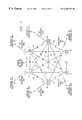
- FIG. 1illustrates an overall block diagram of the distributed network
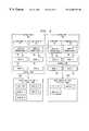
- FIG. 2illustrates a more detailed view of each of the nodes
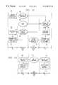
- FIG. 3illustrates a more detailed view of each of the nodes and their internal configuration and the architecture of a non-secured, joined multi-party conference
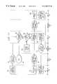
- FIG. 4illustrates the architecture of the architecture of a secure, joined, multi-party conference
- FIG. 5illustrates a diagrammatic view of the architecture of a non-secured broadcast application of the present invention
- FIG. 6illustrates a diagrammatic view of the architecture of a secure broadcast application of the present invention
- FIG. 7illustrates a diagrammatic view of the architecture of a disjunctive, multi-party application of the present invention
- FIG. 8illustrates the conferee's view of a disjunctive, multi-party application of the present invention
- FIG. 9illustrates a diagrammatic view of the architecture of a set of disjunctive, overlapping conferences
- FIG. 10illustrates a flowchart that depicts the process of initiating a simple joined conference
- FIG. 11illustrates a flowchart that depicts the process of joining a node to an existing joined conference
- FIG. 12illustrates a flowchart that depicts the process of initiating a disjunctive conference
- FIG. 13illustrates a flowchart depicting the process of joining two disjunctive conferences
- FIG. 14illustrates a flowchart depicting the process of terminating a conference
- FIG. 15illustrates a diagrammatic view of the process of audio data transmission and reconstruction
- FIG. 16illustrates a diagrammatic view of the process of video data transmission and reconstruction
- FIG. 17illustrates a flowchart depicting the process of audio and video synchronization
- FIG. 18illustrates the features for data recording and playback
- FIG. 19illustrates a flowchart depicting the features for the video answering machine
- FIG. 20illustrates a diagrammatic view of the various fields in a packet of data sent over the network
- FIG. 21illustrates a block diagram of the overall system for two nodes interacting with each other.
- FIG. 22illustrates a more detailed block diagram of a given node.
- FIG. 1there is illustrated a diagrammatic view of a distributed network operating according to the present invention.
- Each of these nodesis interfaced to a global network 12 or a subset of the global network 12 (referred to hereinafter as “the network”).
- IP addresscontains sufficient information to uniquely identify a network and a specific computer on the network 12 .
- these addressesare used to move traffic (messages) from router to router across the network backbone to their eventual recipient. It is this address that is also utilized at the local level by the local network hardware such as servers, routers, concentrators and hubs to switch messages to the appropriate destination.
- the network 12is considered to consist of four architectural layers: the Application Layer, the Transport Layer, the Internet Layer and the Physical Layer.
- the application layerconsists of applications that make use of the network.
- the transport layerprovides end-to-end delivery of messages.
- the internet layerdefines the datagram and handles the routing of datagrams.
- the datagramis the packet of data manipulated by the IP protocol and contains the source address, destination address and data, as well as other control fields.
- the physical layeris beyond the scope of this discussion.
- the TCP/IP standardmakes no effort to define the underlying network physical connectivity. Instead, it makes use of existing standards, such as those that define RS232, EthernetTM and other electronic interfaces used in data communications.
- the logical IP addressis generally different from the physical address of the network hardware.
- the Address Resolution Protocol (ARP)is used to map the logical IP addresses and host names into the physical addresses needed by the underlying network hardware. For example, if an EthernetTM was in use on the local node, the node's response to an ARP request would be the 48-bit number that uniquely identifies every EthernetTM device in existence. This level of network management is handled by the hardware responsible for the physical and internet layers.
- the IP address informationallows a particular network element to recognize information destined for themselves and to extract that (and only that) information from the network data flow.
- IP protocolsThe Transmission Control Protocol (“TCP”) is a transaction format designed to ensure that data is delivered in order and without corruption. TCP provides a reliable stream-oriented delivery service with end-to-end error detection and correction. The reliability of TCP comes from the inclusion of a checksum into each packet and checksum processing upon receipt to ensure that incomplete datagrams are identified and resent. TCP messages are addressed to a specific user with a single defined address on the network 12 .
- TCPTransmission Control Protocol
- UDPUser Datagram Protocol
- UDPprovides “connectionless” packet delivery.
- UDP data deliveryis unreliable and the data may be lost, duplicated or arrive out of order.
- UDP messagesare also addressed to a single specific user, a process often described as “unicast.”
- IPMCIP multicast protocol
- host groupa group of IP addresses in the special range of 224.0.0.0 to 239.255.255.255.
- a multicast datagramis delivered to all members of its destination host group with the same “best efforts” reliability as a regular unicast IP datagram.
- the membership of the host groupis dynamic; that is, hosts may join and leave the group at any time. There is no restriction on the location or number of members of a host group.
- the hostmay be a member of more than one group at a time.
- the overall effectis that, by using the multicast protocol, data can be transmitted on the network 12 in such a manner that multiple nodes can retrieve it without having separately addressed messages. IPMC data delivery is unreliable by design and the data may be lost, duplicated or arrive out of order.
- the bandwidth of a multiparty conferencecan be computed as [nb(n ⁇ 1)] where n is the number of nodes involved in the conference and b is the bandwidth required by each node to transmit audio and video data.
- the number of data streamsis simply equal to [nb] where n is the number of nodes involved in the conference and b is the bandwidth required per node. While all transmission protocols perform similarly when n is equal to 2, the amount of bandwidth required becomes increasingly significant as the number of nodes in the conference grows.
- TCP/IP transactionsare utilized by the application for messaging and control. While the network is actually a uniform IP-based network, all TCP/IP messages are considered hereinafter to belong to a set called the “TCP/IP layer” or the “messaging layer 16 ”.
- the present systemutilizes UDP and multicast transactions to transfer audio and video data between nodes.
- the present systemmay use the UDP and multicast protocols interchangeably.
- the IP multicast protocolis employed.
- IPMCIP Multicast
- UDPUser Datagram Protocol
- each of the nodes 10has associated therewith a group of processes, called hereinafter as a generic class “the audio/video/data cells” 18 , labeled “A/V/D cells.” These are independent functions that collect audio, video and other data, transmit this to other nodes through the data transmission layer 14 , receive information from the data transmission layer 14 and display it to the end user.
- Each node 10also has associated therewith a conference configuration cell 22 that controls the A/V/D cells 18 of the node.
- Each of the conference configuration cells 22is an independent, configurable application that communicates through the network with the other conferencing nodes' configuration cells 22 to exchange the configuration and control data necessary to start, maintain and terminate a conference. Since this information is critical to the successful continuation of the conference, the guaranteed-delivery messaging layer 16 is used to carry these messages. However, because the amount of information needed for this purpose is small, the bandwidth required by the operation of the messaging layer 16 is very low.
- each of the nodes 10is operable to set up a video conference by using the conference configuration cell 22 to interface with other nodes 10 through the messaging layer 16 .
- the nodes' conference configuration cells 22interchange information over the messaging layer 16 as to whom the conferees are in a particular conference and maintain an address table that describes the conference. This table contains the network addresses of every node in the conference, including both the node's address on the messaging layer 16 and the set of addresses (if different) that the node will use to send audio and video information on the data transmission layer 14 . Once this information is available, conferencing can be initiated.
- the address used to conference between nodesmay be identical to the node's IP address on the messaging layer 16 .
- IP multicast addressesmay be used. In this case, it is necessary for the conference configuration cell 22 to identify the addresses of the data streams for each node 10 and then to instruct the network interface processor to “listen” to those addresses to obtain the information from the data transmission layer 14 .
- the delivery mechanism employed on the transport layeronce the information is available to each node, it is processed by the A/V/D cells 18 and displayed as the conferee that the node has specified. This is to be compared with prior art video communications systems where all information from a given node had to be assembled by that node or by a server/host/master in a manner that was appropriate for each receiving node and separately transmitted to that node.
- the present systemsubstantially eliminates the need for a such client/server or master/slave operation.
- each node 10has the ability to independently determine the makeup of the conference at that node. Since all conferees are provided with information as to whom the other conferees are, and since each conferee has independent access to the audio and video streams 20 from each other conferee's node, each individual conferee can determine what or whom they wish to view or hear and configure their conference accordingly. In the present system there is, therefore, no reason that any two conferees must view the conference in exactly the same manner. This is, again, different from prior art, which offered the individual conferee little or no such control.
- each systemoperates asynchronously and simultaneously with respect to the other systems.
- This asynchronous operationis defined in the “connectionless” protocols whereby the nodes retrieve information in the form of a stream of data (either audio and/or video) from the data transmission layer 14 at an unspecified rate.
- the transmitting systemplaces the information onto the data transmission layer 14 at a given rate, which rate is a function of the particular hardware utilized at the transmitting node and other parameters.
- the receivermay have different hardware and may not have the ability to accept information at the same rate that it is being placed onto the network. Because there is no interlocked “handshaking” between the transmitting and the receiving nodes, the receiving node does not have to receive data as fast as it is being transmitted.
- each of the nodesmay select its own compression factors on its outgoing data. Further, each node may transmit data at different frame rates and with different video formats (PAL or NTSC). Receiving nodes are enabled to process a plurality of incoming data streams at different levels of compression as well as at differing speeds and characteristics. Finally, through the addition of specialized hardware, each of the nodes 10 may also accept incoming information in other protocols than the IP protocols and translate this data to IP protocol data that can be managed over the network.
- FIG. 1depicts a system wherein information may be interchanged between multiple nodes wherein each node may have wholly different characteristics, both in terms of the characteristics of its outgoing data and in terms of the management and display of the incoming information.
- FIG. 2there is illustrated a more detailed block diagram of a number of nodes in the system.
- the nodesare labeled node A 56 , node B 58 and node N 62 . These nodes are identical to the nodes 10 of FIG. 1 .
- Each of the nodeshas associated therewith a network cell or cells 26 , which are operable to receive information from the A/V/D cells 18 or the configuration cells 22 and transmit the information to another node via either the messaging layer 16 or the data transmission layer 14 , as specified by the cell requesting the information transfer.
- Each of the nodesalso has associated therewith a network interface processor (typically a “NIC,” a network interface card) 32 that interfaces with the physical layer of the network to receive and send information.
- a network interface processortypically a “NIC,” a network interface card
- the network interface processor 32When handling UDP data, the network interface processor 32 simply accesses those messages associated with the node's own IP address.
- the network interface processor 32When instructed to handle multicast data, the network interface processor 32 has the ability to obtain all necessary information from the network by accessing messages with the appropriate multicast addresses. The address from which information is to be obtained is provided to the network interface processor 32 through the network cell(s) 26 by the cell that wishes to obtain or send information.
- the network interface processor 32 and the network cells 26function together to remove the headers added at the transport, internet and physical layers and to transfer the incoming data to the control of the requesting cell.
- the confereemay not wish to obtain all of the information that is part of a single conference. For instance, in a video conference with a large number of participants, the conferee may wish to hear all of the participants, but to simplify their display by viewing only one or two of the participants. In this case, the user may configure the audio and video cells 18 so as to cause them to obtain all of the audio streams, but only some of the video streams.
- the audio cellsprocess the multiple incoming audio streams that are then merged and played back on the conferee's audio output device.
- the video cellsprocess the incoming video streams and output them to the appropriate video memory locations for transfer to the conferee's display unit. This process is described in more detail hereinbelow.
- each of the conference configuration cells 22is functional to interface through the messaging layer 16 with the other nodes in the system to configure and control their interaction. For example, if node A 56 wanted to enter into a conference with node N 62 , it would send a message to node N 62 , asking node N 62 to be in the conference. Node N 62 would reply that it would like to join the conference and send sufficient information to node A 56 that the two nodes (node A 56 and node N 62 ) could populate their internal address tables 36 , create the appropriate audio, video and network cells 18 , 26 and commence conferencing.
- Both node A 56 and node N 62would then have knowledge of the addresses on the data transmission layer 14 necessary for their conference. If a third node, node B 58 , were subsequently to enter the conference, the preferred embodiment would allow the entry of node B 58 by either of two methods. In the first case, one of the already-conferencing nodes, node A 56 or node N 62 , would initiate contact with node B 58 . In the second case, node B 58 would contact either node A 56 or node N 62 . In either case, a conference request is generated and accepted. Node B 58 supplies its conferencing addresses and it interacts with the node that it has contacted to allow it to create the necessary cells and to create and propagate address tables 36 so that all of the nodes already in the conference can be updated with the addresses of the new nodes.
- any nodemay leave the conference, join other participants in the conference or transfer their session to yet another node. If it is a node that is not already in the conference, it may request to join itself to the conference.
- the joining, subtraction and transferring of nodesrequire no action on the part of the other nodes, except the acceptance and updating of their conference tables and the creation or destruction of the processing cells 18 , 26 as needed to handle the changing data streams.
- Each of the nodesindependently configures itself and is not dependent on any other node for configuration or processing instructions except inasmuch as that other node may change the characteristics of its own data transmission.
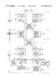
- FIG. 3there is illustrated a detailed block diagram of one of the nodes 10 .
- the node 10 illustrated in detailis labeled node N and is shown in conference with nodes B, C and D.
- Node A 56is transmitting audio and video to the multicast addresses on the data transmission layer that are designated as addresses 252 .
- Node B 58is transmitting audio and video to the addresses on the data transmission layer that are designed as addresses 254 .
- Node Cis transmitting audio and video to the addresses on the data transmission layer that are designated as addresses 258 .
- An individual network cell 26has been created for each address and is associated with a given process cell 42 , 46 .
- the network interface processor 32is instructed by the network cells 26 of node N to obtain information from the data transmission layer addresses of those particular three conferees.
- receiving audio cell 42active on the user's node for each address on the data transmission layer.
- This cell 42is operable to utilize its associated network cell 26 to receive the audio from the address 252 , 254 or 258 on the data transmission layer 14 where the other node has placed it, to process the audio data and play it back on a line 44 to a speaker or some other sort of audio output device.
- Multiple audio cellsmay simultaneously be in operation, each delivering audio data to the hardware 44 that manages sound processing.
- receiving video cell 46which is operable to utilize its network cell 26 to receive data from the address 252 , 254 or 258 on the data transmission layer 14 with which it is associated. It manages the processing of the data and delivers the converted video data to the user's display 34 . Multiple video cells may simultaneously be in operation, each delivering video data to the hardware 34 that manages display processing.
- Local audio and videoare handled in specialized cells 52 , 50 . These cells, which are described in more detail hereinbelow, are operable to receive the audio and video data from the local input devices, which data is encoded in such a manner that it is ready for transmission. The purpose of such encoding is to reduce the amount of bandwidth that is needed for the transmission of the data on the network by compressing the data.
- the output of the local audio 52 and video 50 processing cellsis transferred through the network cell(s) 26 and the network interface processor 32 to the addresses on the data transmission layer 250 that have been obtained by that node as the locations for the audio and video transmission. Uncompressed local video is also routed for display on the user's own display as a “self-view” image.
- FIG. 4there is illustrated an alternate application of the conferencing network of the present system.
- a secured version of the conferencing architecturethere is provided a plurality of nodes, herein represented by six nodes.
- These six nodeswhich are identical to the nodes 10 of FIG. 1, are joined in a conference; they exchange command and control information 24 over the messaging layer 16 and each transmits its own audio and video data 20 to its addresses on the data transmission layer 38 from which location the other nodes retrieve it.
- the conference configuration cell 22 of every nodecan exchange data with the conference configuration cell 22 of every other node through the messaging layer 16 . This is normally used, as described hereinabove, for the exchange of conference command and control information.
- secured modehowever, a variety of techniques are used to encrypt or control access to information on the data transmission layer and the information necessary to maintain that control is exchanged by the nodes on the messaging layer 16 and stored in each node's conference control tables.
- the nodesmay encrypt this information.
- the addresses of the audio and video data streams on the data transmission layer 38may be dynamically changed during the conference.
- additional encrypted address informationmay be exchanged between the nodes over the messaging layer 16 during the conference as part of the address reallocation process.
- the data streams on the transmission layer 20may be encrypted or otherwise secured and the security keys and the encryption/decryption instructions separately transmitted over the messaging layer 16 .
- FIG. 5there is illustrated a diagrammatic view of a broadcast application of the present system.
- broadcast node 70the various nodes are divided into a single broadcast node 70 and a plurality of receiving nodes 72 .
- Each of the nodes 70 and 72are identical to the nodes 10 in FIG. 1 in that they all have the capability to enter into standard video conferences in accordance with the operation of the system described herein.
- one node (“the broadcast node”) 70is configured such that it transmits data to its audio and video addresses on the data transmission layer 14 , but does not create network cells to retrieve any information from any other node.
- the nodeobtains its multicast addresses on the data transmission layer as described hereinabove, defines itself as a broadcast node and commences transmitting its audio and video data to its addresses on the data transmission layer 14 .
- Any node that wishes to receive the broadcastcan obtain the addresses of the broadcast by communicating through the messaging layer 16 with the broadcast node.
- the receiving nodes 72After receiving the data from the multicast addresses of the broadcast node, the receiving nodes 72 then create the audio, video and network cells needed to receive and display the broadcast information. In this application, the receiving nodes do not need to send audio and video data, as neither the broadcast node 70 nor any other node needs this information. As a result, the receiving cells do not obtain multicast addresses on the data transmission layer 14 nor do they transmit data to these addresses.
- a receiving node 72monitors a number of broadcast channels. For example, there could be a number of broadcast nodes 70 , each transmitting audio and video information. A receiving node 72 could actually receive multiple broadcast stations 70 , display video from all of those stations and allow the user to specify the one to which they wish to listen. This is very similar to the feature whereby multiple sports channels can be viewed at the same time on the same television screen, but the audio of only one channel is played.
- FIG. 6there is illustrated a diagrammatic view of another application of the present system.
- This configurationprovides a secure mode none-joined, one-way transmission (broadcast).
- the messaging layer 16is also utilized to transfer information that is used to secure the data on the data transmission layer 14 .
- one node(the “broadcast node”, 70 is configured such that it will transmit data to its audio and video addresses on the data transmission layer 14 , but will not use its network cells to retrieve any information from any other node.
- the nodeobtains its addresses on the data transmission layer as described hereinabove, defines itself as a broadcast node and commences transmitting its audio and video data to its addresses on the data transmission layer 14 .
- Any node that wishes to receive the broadcastcan obtain the addresses of the broadcast by communicating through the messaging layer 16 with the broadcast node.
- the nodesmay encrypt this information 40 .
- the addresses of the audio and video data streams on the data transmission layer 14may be dynamically changed during the conference. In this case, additional encrypted address information may be exchanged between the nodes over the messaging layer 16 during the conference as part of the address reallocation process.
- the receiving nodes 72then create audio, video and network cells 26 to receive and display the broadcast information. In this structure, the receiving nodes do not need to send audio and video data, as neither the broadcast node 70 nor any other node needs this information. As a result, the receiving cells do not obtain addresses on the data transmission layer 14 nor do they transmit data to these addresses.
- the data streams on the transmission layer 14may be encrypted or otherwise secured and the security keys and the encryption/decryption instructions separately transmitted over the messaging layer 16 .
- Each conferenceis composed of multiple nodes. These nodes are identical to the nodes 10 of FIG. 1 .
- the users at nodes A 56 and B 58have knowledge of each other as well as node N 62 and are, thus, participating in a logically joined conference (Conference A, 64 ).
- the users at nodes C 60 and D 48have knowledge of each other, as well as node N 62 and are also participating in a logically joined conference (Conference B, 66 ).
- the two conferencesare fundamentally disjunctive; participants in conference A 64 have no knowledge of conference B 66 and vice versa.
- the conference control tablescontain the addresses of nodes A, B, C, D and N (itself).
- the user at node N 62must manage their outgoing audio and video such that the two conferences remain separate. This is accomplished by allowing node N to obtain more than one set of addresses on the data transmission layer 14 and to represent itself to each conference separately by using the different addresses 250 , 256 .
- the user at node Nuses the normal features for outgoing audio and video control (mute/on) to prevent transmitting unwanted audio or video to either of the conferences.
- FIG. 8there is illustrated a block diagram of a configured conference that illustrates the versatility of the present system.
- the useris participating in both joined and non-joined conferences. These may be either one-way (broadcast) or multi-way conferences.
- This figuredemonstrates the situation from the user's point of view.
- conference A 64 and conference B 66each of which consists of three conferees.
- Conference Aconsists of nodes N, A and B
- conference Bconsists of nodes N, C and D.
- the useronce the conferences have been established, can then decide whether to display all members of all conferences, all members of any specific conference or any member of any conference.
- the nodehas access to all of the information generated by all of the conferees in each of the conferences, since all of the information exists on the data transmission layer.
- FIG. 8illustrates a case in which the user of the system has configured their node such that they are displaying (in view 1 , 280 ) all the conferees in all the conferences.
- the second configurationview 2 , 282
- the user's audio cellsare configurable to allow the user to select the audio streams that should be played back on the user's audio output device.
- FIG. 9there is illustrated a diagrammatic view of disjunctive overlapping conferences.
- the features described hereinabove with reference to FIG. 7 that support separate disjunctive conferencesalso introduce the possibility of overlapping disjunctive conferences where the set of the participants of one conference may subset or overlap the set of the participants of another active non-joined conference.
- the user of node N 62is involved in two disjunctive conferences, Conference A and Conference B.
- Conference A 64involves the users at node N 62 , node A 56 and node B 58 .
- Conference B 66involves users at node N 62 , node C 60 and node D 48 .
- Node Nhas obtained two sets of multicast addresses on the data transmission layer 250 and 256 for this purpose.
- the user at node Ncould create yet another conference, which consists of a separate conference involving the users of node B 58 and node C 60 .
- Thisis logically analogous to the physical situation of participating in several conversations at once. It is likely, therefore, that the participation of users B, C and N in the original conferences will be affected by their membership in the secondary conference and it is, furthermore, unlikely that the other participants in the original conferences would fail to notice such dual participation. However, the feature is supported and the interaction is permitted.
- the nodein addition to the features described hereinabove with respect to FIG. 7, whereby user at node N has control over the incoming data such that the node can display all or any combination of the data streams, the node also has the ability to control outgoing video and audio.
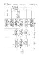
- FIG. 10there is illustrated a flowchart depicting the processing steps that must be executed to start a conference where no conference previously exists.
- the nodesare identical to the nodes 10 in FIG. 1 .
- the present systemrests in a wait state on the node, utilizing minimal system resources.
- a processis launched whereby:
- node N 62the user of node N 62 indicates the node (node A 56 in the example) with which the conference is to be initiated. As a result, node N 62 obtains a set of addresses on the data transmission layer that it will use for audio and video data transmission as indicated by a block 80 ;
- Node N 62exchanges a series of messages as indicated by a block 82 with node A 56 , identifying itself, authenticating the connection and requesting a conference. At the end of this exchange, a message is sent that contains the addresses on the data transmission layer 14 that node N 62 will use for its audio and video data transmission;
- node A 56may not be able to conference; it may be off-line, it may not have the application enabled, it may be set by its user in do-not-disturb (DND) state, the user may be busy, may not be available to answer the call or may not wish to answer the call. In all of these cases, the connection acceptance validation fails as indicated by a block 84 and the user of node N 62 is notified as indicated by a block 86 that the conference will not take place;
- DNDdo-not-disturb
- node A 56if node A 56 wishes to accept the call, it also obtains addresses on the data transmission layer 14 , updates its conference table and creates audio and video data cells that are bound to network cells that are uniquely associated with the addresses of node N 62 . These are immediately operable to retrieve the information from the data transmission layer 14 .
- Node A 56passes the addresses as indicated by a block 90 that it will use on the data transmission layer 14 through the messaging layer 16 to node N 62 ;
- Node N 62updates its conference table as indicated by a block 92 , such that it now contains both its own addresses and those of node A 56 and creates audio and video data cells that are bound to network cells that are uniquely associated with the addresses of node A 56 .
- Both nodesnow start transmitting 94 audio and video data 20 to their transmission addresses on the data transmission layer, as indicated by block 94 .
- each nodeconfigures its own conference; the appearance and content are totally Linder the control of that node. While all audio and video cells initially launch active windows, these can be tailored by the user to meet their own requirements: deactivated, sized, muted or otherwise manipulated.
- FIG. 11there is illustrated a flowchart depicting the flow of program control during the addition of a conferee to an existing conference.
- the nodes in the conferenceare labeled node A 56 and node B 58 .
- the joining nodeis labeled node N 62 .
- These nodesare identical to the nodes 10 in FIG. 1 .
- the nodesOn both sides of the conference, the nodes must maintain the knowledge of the conference in its entirety as described by the combination of the multicast addresses of the participants, this defining a logical group. The purpose of this is to ensure that when another conferee is added, each node can update the tables that describe the conference in the logical group for that node such that (a) the existing conferees can receive notice of the new conferee and (b) the new conferee can receive notice of the existing conferees in the logical group. This process is described in more detail hereinbelow.
- node N 62indicates the node (node A 56 in the example) with which the conference is to be initiated and node N 62 obtains the addresses that it will use for audio and video data transmission, as indicated by a block 80 ;
- Node N 62exchanges a series of messages, as indicated by a block 82 , with node A 56 , identifying itself, authenticating the connection and requesting a conference. At the end of this exchange, a message is sent to node A 56 that contains the addresses on the data transmission layer 14 that node N 62 will use for its audio and video data transmission;
- node A 56may not be able to conference; it may be off-line, it may not have the application enabled, it may be set by its user in do-not-disturb (DND) state, the user may be busy, may not be available to answer the call or may not wish to answer the call. In all of these cases, the connection request is rejected, as indicated by a block 84 , and the user of node N 62 is notified that the conference cannot proceed, as indicated by a block 86 ;
- DNDdo-not-disturb
- node A 56Since node A 56 is already in conference, it already has a set of addresses on the data transmission layer 14 and is transmitting its audio and video data streams to those addresses, as indicated by a block 96 . If the user at node A 56 does not wish to reject the conference from node N 62 , the user at node A 56 must determine whether node N 62 should join an existing conference or be in a separate, disjoined conference. This choice is indicated by the execution of a “JOIN” operation 98 at node A 56 when the audio and video cells for node N 62 are created at node A 56 .
- node A 56simply updates its conference table with the addresses of node N 62 , and sends the updated conference table to node N 62 (the joining node) and to all other nodes in the conference (in this illustration, node B 59 ).
- All nodesupdate their conference tables, as indicated by a block 102 , create the necessary audio, video and network cells, notify their user(s) that there is a new participant and allow their user to configure the data streams from the new conferee as they may wish.
- the set of addresses that define a conference and the conferees thereindefine the logical group and must be available by all conferees in a conference. However, if a node alters this set of addresses at its location, this will constitute a “local group,” which set of addresses are not available to the conferees in the logical group.
- Node Nstarts transmitting its audio and video data 20 to the data transmission layer and conferencing commences, as indicated by a block 94 .
- the initiatorhas relinquished control of the conference, and any conferee in the conference can now initiate the addition of another conferee.
- a nodeIn most cases, a node will only participate in a single conference at a time. However, there is a possibility that multiple nodes may participate simultaneously in separate and non-overlapping (“disjunctive”) conferences. This situation arises when a participant in an existing conference makes a connection with a new conferee but does not join them to the existing conference. In this situation, the nodes must exchange only subsets of the conference configuration tables. This is illustrated in FIG. 12, which is an expansion of the situation depicted in FIG. 11 .
- the procedural flowis identical to the procedural handling of a joined conference in FIG. 11 until the point is reached, as indicated by a block 98 , where the user of node A 56 determines that node N 62 is not to be joined to the existing conference 96 but remain a separate (disjunctive) conference 106 .
- Node A 56then obtains a second set of addresses on the data transmission layer 14 and creates a conference sub-table, which contains the addresses of node N 62 and those of node A 56 .
- the purpose of having different transmissionsis to allow the conferee at the node to selectively mute the outgoing audio and/or video data streams to either of the conferences.
- Node A 56sends a conference acceptance message 90 through the messaging layer 16 to node N 62 . This includes the addresses that node A 56 will use on the data transmission layer 14 .
- Node N 62generates a conference table that consists of both its own addresses and those of node A 56 and launches the audio, video and network cells that are bound to node A's addresses 92 .
- Node A 56begins transmitting 94 , audio and video data, as indicated by a block 20 , to the new addresses on the data transmission layer 14 .
- the transmissionis identical to the data transmission going to the other addresses on the data transmission layer 14 until the user at node A changes it in some manner.
- Node N 62now starts transmitting audio and video data, as indicated by a block 20 , on the data transmission layer 14 .
- This featureallows users to have separate, simultaneous conferences.
- FIG. 13there is illustrated a flowchart for joining disjunctive conferences.
- node Nis considered to be a member of two disjunctive conferences, Conference A and Conference B.
- the following actionstake place:
- Node N 62is transmitting data and video on to conference A 64 using one transmitting address 250 and is also transmitting data and video to Conference B 66 on a separate address 256 .
- the conference configuration cell of node N 62examines at a block 270 the sub-tables within the conference address table 36 to determine which of the two conferences has the fewest members (for the purpose of illustration, this is considered to be conference A);
- Node N 62updates its own addresses 272 in the conference sub-table that describes conference A to contain, instead, the addresses on the data transmission layer that it is utilizing for conference B.
- Node N 62creates at a block 274 a transaction 278 on the messaging layer to all members of conference A and conference B that contains the updated address table and join instructions.
- All members of conference Aupdate their tables 102 and, for purposes of obtaining the video and audio of node N 62 , utilize the updated addresses that were sent in the conference table. These are the addresses that node N was formerly using only with the members of conference B 256 plus the addresses of all the members of conference B.
- All members of conference Bupdate their tables at a block 102 to contain the new members of the conference (formerly members of the non-joined conference A).
- All users in the conferenceconfigure their displays as they may wish to display the information from the additional sessions, as indicated in block 94 .
- Node N 62ceases transmitting, as indicated by block 276 , audio and video data on the addresses that it had originally obtained for use during conference A 276 .
- FIG. 14there is illustrated a flowchart depicting the operation of dropping a conferee.
- a “hang up” message 112is sent that notifies all other conferees that it is going to drop from the conference;
- the other nodesupon receipt of the hang-up message 112 , destroy, as indicated by a block 110 , the cells that they were using to receive data from the node and perform any housekeeping actions necessary to release resources to other processes.
- FIG. 3there is illustrated a block diagram of the local audio and video cells. These cells manage the processing that converts the raw analog video and audio information to a format suitable for transmission. These cells are constructed differently from the receiving audio and video cells that manage the incoming audio and video data streams from the network. These cells are unique and are created as needed.
- the video data processor 30performs all of the processing necessary to convert the raw input video to a compressed digital video stream.
- the incoming analog video signalis initially processed through an analog-to-digital converter (not shown).
- the signalis then routed to two locations; to the user's self view window 40 (if one is active) and to the video encoder/decoder (“codec”) portion of the video data processor 30 .
- the video codeccompresses the video data stream such that the number of bits necessary to accurately represent the video image is reduced to a fraction of the original quantity of bits.
- the local video cell 50is operational to submit the compressed video stream to its associated network cell 26 . This cell functions with the network interface processor 32 to transmit the data to the appropriate address 250 on the data transmission layer 14 .
- the user's sound card 28performs all the processing necessary to convert the raw input analog audio to a digital data stream.
- the local audio cell 52receives this data stream and submits it to its associated network cell 26 for transmission to the appropriate addresses 250 on the data transmission layer 14 . Since the user can hear all sound generated at their node, there is no requirement to output audio to the local node.
- the network cells 26perform the functions necessary to prepare the data for transport and release the data to the network interface processor 32 move the data through the physical network layer.
- FIG. 15there is illustrated a diagrammatic view of the disassembly, transmission and re-assembly of the audio data. This is illustrated as occurring between two nodes, node N 62 and node A 56 , each of which is identical to the node 10 in FIG. 1 .
- a system clockAt the node transmitting the audio and video information (node N, 62 ), there is provided a system clock.
- This system clockis operable to synchronize the generation of the video fields for a given picture and the audio data stream.
- the local audiois encoded in pulse code modulation (PCM) format.
- PCMpulse code modulation
- This informationis composed of a plurality of samples, A 1 , A 2 . . . An 136 .
- the network cellworking with the network interface processor 32 , as described hereinabove, segments the audio data stream data into packets, addresses it and transfers the data 136 to its associated address 250 on the data transmission layer 14 .
- the network interface processor 32 and the network cell 26 that is associated with the address of the audio data for node N 250function together to remove the headers added at the transport, internet and physical layers and make the incoming data available to the receiving audio cell.
- the incoming dataare the fields 126 , 128 and 130 described hereinbelow with respect to the data packet format outlined in FIG. 21 .
- This datais then transferred to the receiving audio cell 42 of node A where the data is subjected to a synchronization check 142 . Synchronization checking is described in detail hereinbelow in the section entitled “AudioNideo Synchronization”.
- the audio cell at the receivermust obtain all packets needed to reconstruct the audio data stream. Since the architecture of the data transmission layer is unreliable by design, the receiving node must evaluate the incoming data stream to determine whether packets of data are missing or have arrived out of order. The audio cell of the receiving node evaluates the time-stamps of each audio packet in respect to the previously received packets and arranges them sequentially in a working buffer. As described hereinbelow, when a packet is determined to be missing, either by comparison with the time-stamp on a video packet or by comparison with the time-stamp on other audio packets, provision is made to compensate for the lost data.
- a portion A 3 of the digital audio data streamis lost or damaged 138 .
- an audio packetis missing, there will be a certain amount of audio information that is not available. This would be noticeable to the user if the data were not replaced, since the absence of audio data cause the audio and video data streams to become desynchronized.
- the receiving audio processing cell 42realizes that audio data is missing, it inserts, as indicated by a block 144 , as much silence into the digital audio data stream as is necessary to fill the gap of the missing data. This is illustrated in FIG. 15 where a lost sample A 3 in the assembled audio stream, as indicated by a block 140 , is replaced by silence.
- FIG. 16there is illustrated a block diagram of the video data processing.
- a system clockAs described hereinabove, at the node transmitting the audio and video information (node N, 62 ), there is provided a system clock.
- the local video cell 50 of node N 62retrieves the value of the system clock each time that it receives a field of compressed video from the video data processor.
- a copy of the system clock valueis included as a “time stamp” that is part of the header for the data.
- the network interface processor 32 of node N 62is responsible for adding the header information needed to ensure the transport of the information through the network to the correct destination address.
- the network interface processor 32 and the network cells 26 that are associated with the address 250 of the transmitting nodefunction to remove the headers added at the transport, internet and physical layers and make the incoming data available to the receiving video cells 46 .
- This datais the fields 126 , 128 and 130 described hereinbelow with respect the data packet format outlined in FIG. 21 .
- These data packetsare reconstructed by the network interface processor 32 and the network cell 26 at the receiving end (node A, 56 ).
- the video cell at the receivermust obtain all the packets needed to reconstruct a single field of compressed video and reassemble these before submitting the field to the video data processor.
- the receiving nodeSince the architecture of the data transmission layer is unreliable by design, the receiving node must evaluate the incoming data stream to determine whether packets of data are missing or have arrived out of order.
- the video cell of the receiving nodeevaluates the time-stamps of each video packet in respect to the previously received packets and arranges them sequentially in a working buffer. As described hereinbelow, when a packet is determined to be missing, either by comparison with the time-stamp on an audio packet or by comparison with the timestamp on other video packets, provision is made to compensate for the lost data. When a video packet is missing, it is not possible to reconstruct the field as required by the decoder.
- the receiving video cell 46when it realizes that it has insufficient video data to complete a field, it sends a duplicate field 144 to the decoder as necessary to fill the gap of the missing data. This is illustrated by the assembled video stream 156 which illustrates one of the samples S 3 , being replaced by the preceding field S 2 .
- FIG. 17there is illustrated a flow chart of the audio/video synchronization process. This illustrates the processes executed to ensure synchronization of audio and video data during a conference between two nodes (node N 62 and node A 56 ). These nodes are identical to the node 10 illustrated in FIG. 1 . As described hereinabove, the transmitting node (node N, 62 ) has a local audio cell 52 and a local video cell 50 . These are bound to individual network cells 26 and use the network interface processor 32 to send data to addresses 152 , 154 on the data transmission layer 14 . The network cells are identical in function, but may be bound to different addresses and processes.
- the receiving node(node A, 56 ) has created network cells 26 that are uniquely associated with the addresses 152 , 154 on the data transmission layer 14 where the sending node (node N, 62 ) is sending its audio and video data.
- the network cell 26 and the network interface processor 32 of node A 56transfer the audio data that has been received from the network to a receiving audio cell 42 .
- the corresponding video data that has been received from the networkis transferred to a receiving video cell 46 . This data is in the format illustrated in FIG. 21 hereinbelow.
- Both the receiving audio cell 42 and the receiving video cell 46evaluate the time stamp of their packets (field 126 of FIG. 21) against the time stamp of the message being held by the other cell.
- the reason for thisis that, as described hereinabove, the data transmission layer 14 is unreliable by design and packets may be lost or damaged in transmission. When a packet is lost, the time stamps under comparison cease to agree and the amount by which they disagree makes it evident whether audio or video data is missing. This makes it possible for the audio and video cells to take appropriate actions to deal with the fault.
- the audio cell 42inserts silence for missing data, while the video cell 46 replicates the previous field of data. In both cases, processing continues with the repaired data in the same fashion as it would have continued with undamaged data.
- FIG. 18there is illustrated a block diagram of a node in near-side recording mode.
- the user of the nodecan direct that the video from the user's own video and audio sources be transferred in encoded format to a storage device.
- the external functional appearance of thisis similar to a conventional VCR.
- the block diagram of FIG. 18is illustrated as a diagrammatic view.
- the select operationis illustrated wherein the user can select the VCR option.
- there are two optionsa record option in a block 286 or a playback option in a block 296 .
- the systemwill flow to a block 288 to obtain and verify the file name and then to a block 290 to accept the data and then write the data to a file. This will then flow to a decision block 294 to determine if the operation has been stopped. If not, the program will continue to accept the data and write the data to the file. If stopped, the program will flow back to the beginning of the program at block 284 .
- datais written to a memory block 292 which is operable to store the audio and video data.
- the programflows to a block 288 to obtain and verify the filename, and then to a block 292 to determine if a specific frame is selected. If so, the program will flow to a block 300 to compute the location, and then to a block 302 to read the file and display the output of the file. If the system is not positioned to a specific frame, the program will flow directly to the block 302 .
- the block 302extracts the data from the memory 292 and passes it to the block 146 to play back the sound device and to the block 150 to transfer information to the video processor for processing as described hereinabove. The reading and displaying continues until stopped, as determined by a decision block 294 .
- the programwill then flow to a decision block 304 to determine if the snapshot feature was selected.
- the snapshot featureallows a user to capture a single image frame and copy it to a file for later use. This is facilitated by the fact that the compression algorithm always transmits the complete picture. If the snapshot feature is not selected, the program will flow back to the input of the block 284 and, if so, the program will flow to a block 288 to obtain and verify the filename, and then to a block 306 to copy the field to a new file. The program will then flow to the block 302 to read the file and display the information.
- the above-noted playback and record featuresare provided to allow the user to record the compressed data stream to disk, to play the data back, to “rewind” or “advance” the data by positioning at specific locations, to stop at any specific frame and review the frame or to copy the selected frame to another file. Additionally, a user can play the video backwards.
- Both the full file and individual imagescan be converted to conventional file formats for playback by parties who do not have the present system installed. These formats can also be used by conventional video and image editing tools.
- the datacan be manipulated with conventional file management tools; it can be sent as an attachment to EMAIL or otherwise transferred to remote users for viewing.
- the useris also allowed to record the far-side data stream.
- Featuresare provided to allow the recording of selected audio and video data streams.
- FIG. 19there is illustrated a diagrammatic view of the video answering machine feature. As illustrated in FIG. 19, the present system is operational to provide an automated answering attendant when the user of the node is unable to accept video conference requests.
- the present systemis operational to provide an automated answering attendant when the user of the node is unable to accept video conference requests.
- node A 56 and node N 62there are illustrated two nodes, node A 56 and node N 62 . These nodes are identical in function to the nodes 10 in FIG. 1 .
- the user of the nodeis permitted to record a message that is to be automatically played to any node attempting to initiate a conference, as indicated by block 162 .
- This messageis recorded to disk, as indicated by block 166 , in the same manner as in the data recording feature illustrated in FIG. 18 .
- the usermay then set the present system in a state whereby it will not accept any conference requests, but will play the message instead.
- node Ais set to such a state at block 164 .
- the receiving nodetests at block 168 to see if it has been set in the answering machine mode. If not, conferencing proceeds as illustrated in FIGS. 10, 11 and 12 . If so, a message is presented to the user of the receiving node that identifies the incoming caller and shows that the incoming call is being automatically answered. The purpose of this is to allow the user of node A (if present) to override the automated answer attendant if they wish.
- the present systemreads, as indicated by block 170 , the data file recorded by the user of node A and transmits this over the messaging layer to the user at node N. It also transmits a message to the user of node N indicating that the user may leave a message at node A if they so wish, as indicated by block 172 .
- node NIf the user at node N does not respond with a message or responds negatively, the session is terminated. If the user does wish to leave a message, node N allows the user to send, as indicated by block 176 , a message 178 to node A, which records it. This is recorded automatically at node A, as indicated by block 188 , in the same manner that audio and video data is recorded with the data recording feature described in FIG. 18 at block 166 .
- Featuresare provided for the user at node A to recognize at block 190 that there are messages waiting and to play back any messages that were received when the auto-answer attendant was set on.
- FIG. 20there is illustrated a diagrammatic view of a packet of audio and/or video data. These are the packets that are sent to the addresses on the data transmission layer.
- the video informationis composed of a plurality of fields.
- each field of compressed videois divided into packets 126 prior to transmission. These may, in turn, be further fragmented by the network processing hardware during the process of transmission.
- a plurality of samples of the audio datacan be transmitted in a single packet 126 .
- Each packetcontains a field 128 which indicates whether the information contained in the packet is audio or video.
- Also contained in the datagramis a time-stamp 130 that is utilized for synchronization of the audio and video data streams.
- the network cell and the network interface processoradd header information 134 that is needed by various processing layers of the network (the transport layer, the internet layer and the physical layer) to move the data to its specified destination.
- This informationis a conventional requirement for transmission over an IP-based network.
- FIG. 21there is illustrated a block diagram of two nodes in the system communicating over the network 14 .
- These nodesare identical to the node 10 depicted in FIG. 1 .
- Each of the nodes, node A 56 and node N 62have a main PCI bus 180 associated therewith.
- the PCI bus 180allows a CPU 182 to communicate with other peripheral systems on the bus 180 .
- This busis compliant with the specification for PCI 2.1.
- a PCI-based VGA interface card 184which interfaces with a display 186 and a network interface processor 32 that interfaces with the network 12 .
- the basic portion of the system that interfaces with the PCI bus 180comprises the video data processor 30 , which is operable to transfer data via the PCI bus 180 to and from the network interface card 32 , the CPU 182 and the memory 192 associated with the CPU 182 .
- the video data processoris also operable to interface with a video source 196 to receive video data and also with a video output device, such as an NTSC or PAL television or VCR 198 .
- the video data processor 30operates under the direction of the local and receiving video cells. These are resident on the CPU and utilize the video data processor for the purposes of video capture, compression, decompression and display. In operation, the video data processor 30 is operable in two modes:
- Local videois submitted directly to the video data processor 192 .
- the local video celldirects the video data processor 30 to transfer its output via the PCI bus 180 to the network interface processor 32 , which operates under the control of the network cells.
- Incoming video informationis received through the network interface processor 32 , managed by the network cell and stored in the memory 192 after removal of the network overhead. It is then released to the control of the receiving video cell, which is resident in CPU 182 .
- the compressed video informationis sent to the video data processor for decompression and video enhancement, processes that are described in more detail hereinbelow.
- ARer processingthe data is in a format that can be directly output to the VGA interface and shown on the VGA display or the NTSC display.
- Incoming audio informationis routed by the receiving audio cell directly to the computer's audio I/O system 28 .
- Local audio datais generated by the audio I/ 0 subsystem 28 .
- This datais processed by the local audio cell and released through the network cell to the network interface processor 32 for transport to the other node. It is noted that video can be transmitted from Node A to Node N in one video format while video transmission in the other direction can be in a different format. This will be described in more detail hereinbelow.
- FIG. 22there is illustrated a more detailed block diagram of each of the nodes.
- the systememploys a conventional PCI-based architecture wherein CPU 182 is interfaced directly with a primary PCI bus 180 .
- the PCI bus 180has limitations inasmuch as it allows only one clock, one grant and one request per physical PCI device. Normally, each PCI slot on the computer's motherboard is expected to host a single PCI device.
- a PCI bridge circuit 200is utilized.
- the integrated circuit that is utilized to realize the operation of the PCI bridge 200is a DEC21152 manufactured by Digital Equipment Corporation. This integrated circuit is operable to interface a maximum of four additional PCI devices to the secondary PCI bus 202 .
- the PCI businterfaces with a video wavelet encoder chip 204 , a video wavelet decoder chip 214 and a scaler processor chip 224 . As described hereinbelow, one slot on the secondary bus is left available for future features.
- the video encodingis performed by a wavelet encoder chip 204 , which is interfaced to the secondary PCI bus 202 through a PCI bus interface 206 .
- the wavelet encoder chip 204interfaces with an associated dynamic random access memory (DRAM) 208 and the PCI bus interface chip 206 interfaces with a boot readonly memory (ROM) 210 .
- the wavelet encoder chip 204is a self-contained integrated circuit, part number ADV 601 , that is manufactured by Analog Devices. This chip interfaces with the secondary PCI bus 202 through an AMCCS5933 integrated circuit, manufactured by AMCC.
- the wavelet encoder chip 204utilizes a conventional wavelet encoding algorithm for the video compression.
- the same wavelet integrated circuitcan also be utilized in a decode operation.
- This functionis provided by a wavelet decoder chip 214 which interfaces with the PCI bus 202 through a PCI bus interface 216 .
- the wavelet decoder chip 214also has a DRAM 218 and the PCI bus interface chip 216 and a boot ROM 220 .
- the wavelet decoder chip 214receives data compressed in accordance with the wavelet algorithm and decompresses the video information for output on the first intermediate video bus 222 .
- the first intermediate video bus 222is operable to be input to the scaler processor 224 , which is a 7146 scaler processor manufactured by Philips.
- the scaler processor 224is a PCI-based device and, therefore, interfaces directly with the secondary PCI bus 202 .
- the scaler processor 224also has a second input that is interfaced with a second video bus 226 .
- This video busis operable to receive the local digital video data for input to the wavelet encoder 204 and to the scaler processor 224 .
- the video that is placed onto the second video bus 226is received from one of two local video input sources 228 or 230 , which are processed through an analog-to-digital converter 232 to provide digital video.
- the first video bus 222is also output through a digital-to-analog converter 212 directly to a video output device 234 , for example, an NTSC or PAL format television or video recorder.
- This featurecan be utilized to support additional devices and protocols.
- many conventional video conferencing systemsutilize the H. 320 /H. 261 standard and communicate over ISDN telephone lines 248 .
- a PCI-based devicethat can accept H. 320 transmission from an ISDN telephone line and translate it to a message that can be sent through the PCI bus 242 , a user can actually interface with systems that process audio and video in completely different formats and protocols than those used by the present system to transmit information over the network.
- processing cellsmust exist and have capability such that, when the user wishes to use data from such systems, the audio and video can be translated from the other format and protocol to that used by the present system. For example, as illustrated in FIG.
- informationwould be received through the global telephone network 245 , processed through the ISDN interface 244 and translated to an appropriate format for display or retransmission. It should be understood that one advantage provided by the present system is that this architecture is specifically expandable to include cells with these translation capabilities.
- the scaler processor 224is operable under the direction of the video cell to interface with the VGA interface card 184 and controls the output data stream. This is a conventional chip and provides that function.
- the scaler processoris operable to provide image sizing (scaling). It is also, however, capable of accepting instructions to mathematically calculate values for missing pixels of information and to perform other complex image processing functions. Thus, under some circumstances, the present system may use the scaler for image smoothing and other functions that improve picture quality.
- the user of the nodeis provided features for:
- a video/audio communications systemthat is operable to communicate between nodes over a network utilizing the protocols of the global communication network. These protocols allow users to transmit video and audio over the network to a defined address that is accessible by one or more nodes on the network.
- the informationcan be accessed by any authorized node.
- Each of the nodes in the networkoperates independently of the other nodes inasmuch as it determines the exact configuration of the call. Furthermore, there exists no server among the nodes to define the operation of any of the systems. Each user on the system can initiate and participate in both two party and multi-party joined conferences as well as multi-party disjoined conferences. The nodes may also operate in a low-overhead one-way “broadcast” mode.
- the audio and video of each nodemay also have different characteristics. Some of the elements that may vary are the video format (NTSC or PAL), the data compression rate and the frame rate of the video. Provision is also made for accepting data in varying protocols.
- the present inventionis capable of receiving and simultaneously processing incoming data with different characteristics and allowing the user to tailor the appearance (or non-appearance) of the data to meet their individual requirements.
Landscapes
- Engineering & Computer Science (AREA)
- Multimedia (AREA)
- Signal Processing (AREA)
- Data Exchanges In Wide-Area Networks (AREA)
- Two-Way Televisions, Distribution Of Moving Picture Or The Like (AREA)
Abstract
Description
Claims (27)
Priority Applications (3)
| Application Number | Priority Date | Filing Date | Title |
|---|---|---|---|
| US08/926,256US6288739B1 (en) | 1997-09-05 | 1997-09-05 | Distributed video communications system |
| AU94723/98AAU9472398A (en) | 1997-09-05 | 1998-09-03 | Distributed video communications system |
| PCT/US1998/018374WO1999012351A1 (en) | 1997-09-05 | 1998-09-03 | Distributed video communications system |
Applications Claiming Priority (1)
| Application Number | Priority Date | Filing Date | Title |
|---|---|---|---|
| US08/926,256US6288739B1 (en) | 1997-09-05 | 1997-09-05 | Distributed video communications system |
Publications (1)
| Publication Number | Publication Date |
|---|---|
| US6288739B1true US6288739B1 (en) | 2001-09-11 |
Family
ID=25452947
Family Applications (1)
| Application Number | Title | Priority Date | Filing Date |
|---|---|---|---|
| US08/926,256Expired - Fee RelatedUS6288739B1 (en) | 1997-09-05 | 1997-09-05 | Distributed video communications system |
Country Status (3)
| Country | Link |
|---|---|
| US (1) | US6288739B1 (en) |
| AU (1) | AU9472398A (en) |
| WO (1) | WO1999012351A1 (en) |
Cited By (129)
| Publication number | Priority date | Publication date | Assignee | Title |
|---|---|---|---|---|
| US20020025045A1 (en)* | 2000-07-26 | 2002-02-28 | Raike William Michael | Encryption processing for streaming media |
| US20020049852A1 (en)* | 1999-12-06 | 2002-04-25 | Yen-Jen Lee | Global messaging with distributed adaptive streaming control |
| US20020103864A1 (en)* | 2000-12-26 | 2002-08-01 | Jeffrey Rodman | System and method for coordinating a conference using a dedicated server |
| US20020112152A1 (en)* | 2001-02-12 | 2002-08-15 | Vanheyningen Marc D. | Method and apparatus for providing secure streaming data transmission facilities using unreliable protocols |
| WO2002065691A1 (en)* | 2001-02-12 | 2002-08-22 | Aventail Corporation | Method and apparatus for providing secure streaming data transmission facilities using unreliable protocols |
| US20020118809A1 (en)* | 2000-12-01 | 2002-08-29 | Alfred Eisenberg | Initiation and support of video conferencing using instant messaging |
| US6466550B1 (en)* | 1998-11-11 | 2002-10-15 | Cisco Technology, Inc. | Distributed conferencing system utilizing data networks |
| US20020193993A1 (en)* | 1998-09-30 | 2002-12-19 | Leviton Dan?Apos;L | Voice communication with simulated speech data |
| US20030005302A1 (en)* | 2001-03-02 | 2003-01-02 | Scott Searle | Theft resistant graphics |
| US6515992B1 (en)* | 1997-12-02 | 2003-02-04 | Two Way Tv Limited | Method and apparatus for input of data |
| US20030028598A1 (en)* | 1999-09-23 | 2003-02-06 | Rocket Network, Inc. | Method and system for archiving and forwarding multimedia production data |
| US20030028593A1 (en)* | 2001-07-03 | 2003-02-06 | Yiming Ye | Automatically determining the awareness settings among people in distributed working environment |
| US20030041162A1 (en)* | 2001-08-27 | 2003-02-27 | Hochmuth Roland M. | System and method for communicating graphics images over a computer network |
| WO2003052613A1 (en)* | 2001-12-15 | 2003-06-26 | Thomson Licensing S.A. | Videoconference application user interface with messaging system |
| US20030142805A1 (en)* | 2000-08-28 | 2003-07-31 | Hagay Gritzer | Digital recording of IP based distributed switching platform |
| US20030156188A1 (en)* | 2002-01-28 | 2003-08-21 | Abrams Thomas Algie | Stereoscopic video |
| US6615239B1 (en)* | 1998-12-16 | 2003-09-02 | International Business Machines Corporation | Automatic presentation exchanger |
| US20030195924A1 (en)* | 2002-04-15 | 2003-10-16 | Franke Michael Martin | Methods and system using a local proxy server to process media data for local area users |
| US6636487B1 (en)* | 1998-12-16 | 2003-10-21 | At&T Corp. | Apparatus and method for providing multimedia conferencing services with an unspecified bit rate quality of service class over an asynchronous transfer mode network |
| US20030206549A1 (en)* | 2002-05-03 | 2003-11-06 | Mody Sachin Satish | Method and apparatus for multicast delivery of information |
| US6662211B1 (en)* | 2000-04-07 | 2003-12-09 | Lucent Technologies Inc. | Method and system for providing conferencing services in a telecommunications system |
| US20040003040A1 (en)* | 2002-07-01 | 2004-01-01 | Jay Beavers | Interactive, computer network-based video conferencing system and process |
| US20040006595A1 (en)* | 2002-07-03 | 2004-01-08 | Chiang Yeh | Extended features to conferencing system using a web-based management interface |
| US6697341B1 (en)* | 1998-12-16 | 2004-02-24 | At&T Corp. | Apparatus and method for providing multimedia conferencing services with selective performance parameters |
| US20040052371A1 (en)* | 2001-08-15 | 2004-03-18 | Koichiro Watanabe | Content providing apparatus and content providing method |
| US20040117446A1 (en)* | 2002-12-06 | 2004-06-17 | Insors Integrated Communications | Methods and program products for organizing virtual meetings |
| US6757531B1 (en)* | 1998-11-18 | 2004-06-29 | Nokia Corporation | Group communication device and method |
| WO2004053658A3 (en)* | 2002-12-11 | 2004-07-29 | Leader Technologies Inc | Context instantiated application protocol |
| US20040172656A1 (en)* | 2003-02-28 | 2004-09-02 | Kim Myong Gi | Two-way audio/video conferencing system |
| US20040170159A1 (en)* | 2003-02-28 | 2004-09-02 | Kim Myong Gi | Digital audio and/or video streaming system |
| US20050114529A1 (en)* | 2001-01-10 | 2005-05-26 | Lambert James P. | Technique of generating a composite media stream |
| US20050122392A1 (en)* | 2003-11-14 | 2005-06-09 | Tandberg Telecom As | Distributed real-time media composer |
| US20050234961A1 (en)* | 2004-04-16 | 2005-10-20 | Pinnacle Systems, Inc. | Systems and Methods for providing a proxy for a shared file system |
| US20050264648A1 (en)* | 2004-05-25 | 2005-12-01 | Victor Ivashin | Local video loopback method for a multi-participant conference system using a back-channel video interface |
| US20060168291A1 (en)* | 2005-01-05 | 2006-07-27 | Van Zoest Alexander | Interactive multichannel data distribution system |
| US20060174026A1 (en)* | 2005-01-05 | 2006-08-03 | Aaron Robinson | System and method for a remote user interface |
| US20060174021A1 (en)* | 2005-01-05 | 2006-08-03 | Roland Osborne | Media transfer protocol |
| US7089285B1 (en)* | 1999-10-05 | 2006-08-08 | Polycom, Inc. | Videoconferencing apparatus having integrated multi-point conference capabilities |
| US20060230106A1 (en)* | 2005-03-18 | 2006-10-12 | Mcdonald Rex E Jr | System and method for real-time feedback with conservative network usage in a teleconferencing system |
| US20060244818A1 (en)* | 2005-04-28 | 2006-11-02 | Comotiv Systems, Inc. | Web-based conferencing system |
| US20060259618A1 (en)* | 2005-05-16 | 2006-11-16 | Lg Electronics Inc. | Method and apparatus of processing audio of multimedia playback terminal |
| US20060271626A1 (en)* | 2005-05-27 | 2006-11-30 | Microsoft Corporation | Supporting a serial and a parallel invitation protocol |
| US20060268753A1 (en)* | 2005-05-27 | 2006-11-30 | Microsoft Corporation | Establishing a multiparty session by sending invitations in parallel |
| US20070005804A1 (en)* | 2002-11-11 | 2007-01-04 | Neil Rideout | Multicast videoconferencing |
| US20070094374A1 (en)* | 2005-10-03 | 2007-04-26 | Snehal Karia | Enterprise-managed wireless communication |
| US20070124381A1 (en)* | 2005-11-22 | 2007-05-31 | Zurko Mary E | Method and system for providing electronic pickup meetings |
| US20070127394A1 (en)* | 2004-02-06 | 2007-06-07 | Nokia Crorporation | Method and system for optimization of data transfer between networked devices |
| US20070139189A1 (en)* | 2005-12-05 | 2007-06-21 | Helmig Kevin S | Multi-platform monitoring system and method |
| US20070153712A1 (en)* | 2006-01-05 | 2007-07-05 | Cisco Technology, Inc. | Method and architecture for distributed video switching using media notifications |
| US20070156829A1 (en)* | 2006-01-05 | 2007-07-05 | Scott Deboy | Messaging system with secure access |
| US20070180029A1 (en)* | 2006-02-01 | 2007-08-02 | Marian Croak | Method and apparatus for restricting visual material for conference services |
| US20070198637A1 (en)* | 2006-01-04 | 2007-08-23 | Scott Deboy | Conferencing system with data file management |
| US20070239827A1 (en)* | 2006-02-13 | 2007-10-11 | Scott Deboy | Global chat system |
| US20070261073A1 (en)* | 2006-04-25 | 2007-11-08 | Xorbit, Inc. | System and method for monitoring video data |
| US20070276910A1 (en)* | 2006-05-23 | 2007-11-29 | Scott Deboy | Conferencing system with desktop sharing |
| US20070282793A1 (en)* | 2006-06-01 | 2007-12-06 | Majors Kenneth D | Computer desktop sharing |
| US20070285501A1 (en)* | 2006-06-09 | 2007-12-13 | Wai Yim | Videoconference System Clustering |
| US20070286366A1 (en)* | 2006-03-17 | 2007-12-13 | Scott Deboy | Chat presence system |
| US20080005245A1 (en)* | 2006-06-30 | 2008-01-03 | Scott Deboy | Conferencing system with firewall |
| US20080021968A1 (en)* | 2006-07-19 | 2008-01-24 | Majors Kenneth D | Low bandwidth chat system |
| US20080043964A1 (en)* | 2006-07-14 | 2008-02-21 | Majors Kenneth D | Audio conferencing bridge |
| US20080065999A1 (en)* | 2006-09-13 | 2008-03-13 | Majors Kenneth D | Conferencing system with document access |
| US20080066001A1 (en)* | 2006-09-13 | 2008-03-13 | Majors Kenneth D | Conferencing system with linked chat |
| US20080065727A1 (en)* | 2006-09-13 | 2008-03-13 | Majors Kenneth D | Conferencing system with improved access |
| US20080091778A1 (en)* | 2006-10-12 | 2008-04-17 | Victor Ivashin | Presenter view control system and method |
| US20080140767A1 (en)* | 2006-06-14 | 2008-06-12 | Prasad Rao | Divitas description protocol and methods therefor |
| US20080220781A1 (en)* | 2006-06-14 | 2008-09-11 | Snehal Karia | Methods and arrangment for implementing an active call handover by employing a switching component |
| US20080267578A1 (en)* | 2007-04-30 | 2008-10-30 | Microsoft Corporation | Insertion of virtual video into live video |
| US20080317241A1 (en)* | 2006-06-14 | 2008-12-25 | Derek Wang | Code-based echo cancellation |
| US20090016333A1 (en)* | 2006-06-14 | 2009-01-15 | Derek Wang | Content-based adaptive jitter handling |
| US7480500B1 (en) | 2006-06-14 | 2009-01-20 | Divitas Networks, Inc. | Divitas protocol proxy and methods therefor |
| USRE40634E1 (en) | 1996-09-26 | 2009-02-10 | Verint Americas | Voice interaction analysis module |
| US20090055475A1 (en)* | 2007-08-24 | 2009-02-26 | Microsoft Corporation | Inviting a conferencing unaware endpoint to a conference |
| US20090092234A1 (en)* | 2007-10-05 | 2009-04-09 | Apple Inc. | Answering video chat requests |
| US20090215438A1 (en)* | 2008-02-23 | 2009-08-27 | Ajay Mittal | Methods for performing transparent callback |
| US20090225873A1 (en)* | 2008-03-05 | 2009-09-10 | Qualcomm Incorporated | Multiple Transmitter System and Method |
| US7716312B2 (en) | 2002-11-13 | 2010-05-11 | Avid Technology, Inc. | Method and system for transferring large data files over parallel connections |
| US7733366B2 (en) | 2002-07-01 | 2010-06-08 | Microsoft Corporation | Computer network-based, interactive, multimedia learning system and process |
| RU2396730C2 (en)* | 2006-06-16 | 2010-08-10 | Эрикссон Аб | Control of conference layout and control protocol |
| RU2398362C2 (en)* | 2006-06-16 | 2010-08-27 | Эрикссон Аб | Connection of independent multimedia sources into conference communication |
| US20100222053A1 (en)* | 2009-02-27 | 2010-09-02 | Girisrinivasarao Athulurutirumala | Arrangement and methods for establishing a telecommunication connection based on a heuristic model |
| US20100322112A1 (en)* | 2009-06-21 | 2010-12-23 | Emblaze-Vcon Ltd. | System and Method of Multi-End-Point Data-Conferencing |
| US7859356B2 (en) | 2008-03-21 | 2010-12-28 | Qualcomm Incorporated | Transmission line system having high common mode impedance |
| US8027339B2 (en) | 1997-03-12 | 2011-09-27 | Nomadix, Inc. | System and method for establishing network connection |
| US8064535B2 (en) | 2007-03-02 | 2011-11-22 | Qualcomm Incorporated | Three phase and polarity encoded serial interface |
| US20120069137A1 (en)* | 2007-09-30 | 2012-03-22 | Optical Fusion Inc. | Synchronization and Mixing of Audio and Video Streams in Network-Based Video Conferencing Call Systems |
| US8156246B2 (en) | 1998-12-08 | 2012-04-10 | Nomadix, Inc. | Systems and methods for providing content and services on a network system |
| US8190708B1 (en) | 1999-10-22 | 2012-05-29 | Nomadix, Inc. | Gateway device having an XML interface and associated method |
| US20120206564A1 (en)* | 2001-05-10 | 2012-08-16 | Polycom Israel Ltd. | Control Unit for Multipoint Multimedia/Audio System |
| US8266269B2 (en) | 1998-12-08 | 2012-09-11 | Nomadix, Inc. | Systems and methods for providing content and services on a network system |
| US20130033563A1 (en)* | 2010-03-04 | 2013-02-07 | Eduardo Fullea Carrera | Multipoint conference method that does not use a server |
| US8412773B1 (en) | 2006-06-28 | 2013-04-02 | Insors Integrated Communications | Methods, systems and program products for initiating a process on data network |
| US8457614B2 (en) | 2005-04-07 | 2013-06-04 | Clearone Communications, Inc. | Wireless multi-unit conference phone |
| US8458340B2 (en) | 2001-02-13 | 2013-06-04 | Aventail Llc | Distributed cache for state transfer operations |
| US8539119B2 (en) | 2004-11-24 | 2013-09-17 | Qualcomm Incorporated | Methods and apparatus for exchanging messages having a digital data interface device message format |
| US8549134B1 (en)* | 2005-02-11 | 2013-10-01 | Hewlett-Packard Development Company, L.P. | Network event indicator system |
| US8606946B2 (en) | 2003-11-12 | 2013-12-10 | Qualcomm Incorporated | Method, system and computer program for driving a data signal in data interface communication data link |
| US8611215B2 (en) | 2005-11-23 | 2013-12-17 | Qualcomm Incorporated | Systems and methods for digital data transmission rate control |
| US8613053B2 (en) | 1998-12-08 | 2013-12-17 | Nomadix, Inc. | System and method for authorizing a portable communication device |
| US8625625B2 (en) | 2004-03-10 | 2014-01-07 | Qualcomm Incorporated | High data rate interface apparatus and method |
| US8630305B2 (en) | 2004-06-04 | 2014-01-14 | Qualcomm Incorporated | High data rate interface apparatus and method |
| US8635358B2 (en) | 2003-09-10 | 2014-01-21 | Qualcomm Incorporated | High data rate interface |
| US8645566B2 (en) | 2004-03-24 | 2014-02-04 | Qualcomm Incorporated | High data rate interface apparatus and method |
| US8650304B2 (en) | 2004-06-04 | 2014-02-11 | Qualcomm Incorporated | Determining a pre skew and post skew calibration data rate in a mobile display digital interface (MDDI) communication system |
| US8667363B2 (en) | 2004-11-24 | 2014-03-04 | Qualcomm Incorporated | Systems and methods for implementing cyclic redundancy checks |
| US8670457B2 (en) | 2003-12-08 | 2014-03-11 | Qualcomm Incorporated | High data rate interface with improved link synchronization |
| US8681817B2 (en) | 2003-06-02 | 2014-03-25 | Qualcomm Incorporated | Generating and implementing a signal protocol and interface for higher data rates |
| US8687658B2 (en) | 2003-11-25 | 2014-04-01 | Qualcomm Incorporated | High data rate interface with improved link synchronization |
| US8692838B2 (en) | 2004-11-24 | 2014-04-08 | Qualcomm Incorporated | Methods and systems for updating a buffer |
| US8694652B2 (en) | 2003-10-15 | 2014-04-08 | Qualcomm Incorporated | Method, system and computer program for adding a field to a client capability packet sent from a client to a host |
| US8692839B2 (en) | 2005-11-23 | 2014-04-08 | Qualcomm Incorporated | Methods and systems for updating a buffer |
| US8694663B2 (en) | 2001-09-06 | 2014-04-08 | Qualcomm Incorporated | System for transferring digital data at a high rate between a host and a client over a communication path for presentation to a user |
| US8705571B2 (en) | 2003-08-13 | 2014-04-22 | Qualcomm Incorporated | Signal interface for higher data rates |
| US8705521B2 (en) | 2004-03-17 | 2014-04-22 | Qualcomm Incorporated | High data rate interface apparatus and method |
| US8723705B2 (en) | 2004-11-24 | 2014-05-13 | Qualcomm Incorporated | Low output skew double data rate serial encoder |
| US8730069B2 (en) | 2005-11-23 | 2014-05-20 | Qualcomm Incorporated | Double data rate serial encoder |
| US8745251B2 (en) | 2000-12-15 | 2014-06-03 | Qualcomm Incorporated | Power reduction system for an apparatus for high data rate signal transfer using a communication protocol |
| US8756294B2 (en) | 2003-10-29 | 2014-06-17 | Qualcomm Incorporated | High data rate interface |
| US8873584B2 (en) | 2004-11-24 | 2014-10-28 | Qualcomm Incorporated | Digital data interface device |
| US8996740B2 (en) | 2012-06-29 | 2015-03-31 | Qualcomm Incorporated | N-phase polarity output pin mode multiplexer |
| US9013539B1 (en)* | 2013-08-30 | 2015-04-21 | Google Inc. | Video conferencing system and method |
| US9060094B2 (en) | 2007-09-30 | 2015-06-16 | Optical Fusion, Inc. | Individual adjustment of audio and video properties in network conferencing |
| US9112815B2 (en) | 2012-06-15 | 2015-08-18 | Qualcomm Incorporated | Three-phase-polarity safe reverse link shutdown |
| US20150379276A1 (en)* | 2014-06-27 | 2015-12-31 | Freescale Semiconductor, Inc. | System on a chip, controller and method for securing data |
| US9231790B2 (en) | 2007-03-02 | 2016-01-05 | Qualcomm Incorporated | N-phase phase and polarity encoded serial interface |
| US20160080784A1 (en)* | 2014-09-11 | 2016-03-17 | Harman International Industries, Incorporated | Methods and systems for avb networks |
| US9711041B2 (en) | 2012-03-16 | 2017-07-18 | Qualcomm Incorporated | N-phase polarity data transfer |
| US20220255665A1 (en)* | 2021-02-10 | 2022-08-11 | Hitachi, Ltd. | Network interface for storage controller |
| US12108013B2 (en) | 2022-07-27 | 2024-10-01 | Zeality Inc | Method and processing unit for controlling viewpoint of attendees in an immersive environment |
Families Citing this family (17)
| Publication number | Priority date | Publication date | Assignee | Title |
|---|---|---|---|---|
| JP2000332908A (en)* | 1999-05-17 | 2000-11-30 | Kyocera Corp | Mobile videophone terminal |
| CN1197335C (en)* | 1999-11-24 | 2005-04-13 | 索尼公司 | Communication system |
| WO2001045406A1 (en)* | 1999-12-17 | 2001-06-21 | Telum (Canada) Inc. | Network-based talk show system |
| DK1201082T3 (en)* | 2000-04-28 | 2003-12-15 | Swisscom Mobile Ag | Video conferencing method and system |
| US8948059B2 (en) | 2000-12-26 | 2015-02-03 | Polycom, Inc. | Conference endpoint controlling audio volume of a remote device |
| US9001702B2 (en) | 2000-12-26 | 2015-04-07 | Polycom, Inc. | Speakerphone using a secure audio connection to initiate a second secure connection |
| US8977683B2 (en) | 2000-12-26 | 2015-03-10 | Polycom, Inc. | Speakerphone transmitting password information to a remote device |
| US8964604B2 (en) | 2000-12-26 | 2015-02-24 | Polycom, Inc. | Conference endpoint instructing conference bridge to dial phone number |
| US8976712B2 (en) | 2001-05-10 | 2015-03-10 | Polycom, Inc. | Speakerphone and conference bridge which request and perform polling operations |
| US8934382B2 (en) | 2001-05-10 | 2015-01-13 | Polycom, Inc. | Conference endpoint controlling functions of a remote device |
| US20020194606A1 (en)* | 2001-06-14 | 2002-12-19 | Michael Tucker | System and method of communication between videoconferencing systems and computer systems |
| EP1304878A1 (en)* | 2001-10-11 | 2003-04-23 | Siemens Aktiengesellschaft | Method for transmission of communication data, video conference and video chat system |
| US8947487B2 (en) | 2001-12-31 | 2015-02-03 | Polycom, Inc. | Method and apparatus for combining speakerphone and video conference unit operations |
| US8934381B2 (en) | 2001-12-31 | 2015-01-13 | Polycom, Inc. | Conference endpoint instructing a remote device to establish a new connection |
| US8885523B2 (en) | 2001-12-31 | 2014-11-11 | Polycom, Inc. | Speakerphone transmitting control information embedded in audio information through a conference bridge |
| NO20071401L (en) | 2007-03-16 | 2008-09-17 | Tandberg Telecom As | System and arrangement for lifelike video communication |
| CN101355682B (en)* | 2007-07-23 | 2011-03-16 | 中兴通讯股份有限公司 | Method for automatically regulating speed of whole network of wideband private wire conference television system |
Citations (43)
| Publication number | Priority date | Publication date | Assignee | Title |
|---|---|---|---|---|
| US5003532A (en) | 1989-06-02 | 1991-03-26 | Fujitsu Limited | Multi-point conference system |
| US5179551A (en) | 1991-04-08 | 1993-01-12 | Washington University | Non-blocking multi-cast switching system |
| US5195086A (en) | 1990-04-12 | 1993-03-16 | At&T Bell Laboratories | Multiple call control method in a multimedia conferencing system |
| US5227875A (en) | 1990-08-20 | 1993-07-13 | Kabushiki Kaisha Toshiba | System for transmitting encoded image data with quick image expansion and contraction |
| US5237571A (en) | 1991-09-26 | 1993-08-17 | Ipc Information Systems, Inc. | Broadcast system for distributed switching network |
| US5243596A (en) | 1992-03-18 | 1993-09-07 | Fischer & Porter Company | Network architecture suitable for multicasting and resource locking |
| US5257306A (en) | 1991-05-29 | 1993-10-26 | Fujitsu Limited | Video teleconferencing system |
| US5289460A (en) | 1992-07-31 | 1994-02-22 | International Business Machines Corp. | Maintenance of message distribution trees in a communications network |
| US5291477A (en) | 1992-08-10 | 1994-03-01 | Bell Communications Research, Inc. | Method and system for multicast routing in an ATM network |
| US5303311A (en) | 1990-03-12 | 1994-04-12 | International Business Machines Corporation | Method and apparatus for recognizing characters |
| US5309430A (en) | 1991-07-22 | 1994-05-03 | Alcatel N.V. | Telecommunication system |
| US5309433A (en) | 1992-06-18 | 1994-05-03 | International Business Machines Corp. | Methods and apparatus for routing packets in packet transmission networks |
| US5325356A (en) | 1992-05-20 | 1994-06-28 | Xerox Corporation | Method for aggregating ports on an ATM switch for the purpose of trunk grouping |
| US5345558A (en) | 1992-11-23 | 1994-09-06 | Synoptics Communications, Inc. | Topology independent broadcast of cells in an ATM network or the like |
| US5361256A (en) | 1992-11-27 | 1994-11-01 | International Business Machines Corporation | Inter-domain multicast routing |
| US5374952A (en)* | 1993-06-03 | 1994-12-20 | Target Technologies, Inc. | Videoconferencing system |
| US5402415A (en) | 1993-04-22 | 1995-03-28 | Washington University | Multicast virtual circuit switch using cell recycling |
| US5408465A (en) | 1993-06-21 | 1995-04-18 | Hewlett-Packard Company | Flexible scheme for admission control of multimedia streams on integrated networks |
| US5412654A (en) | 1994-01-10 | 1995-05-02 | International Business Machines Corporation | Highly dynamic destination-sequenced destination vector routing for mobile computers |
| US5418937A (en) | 1990-11-30 | 1995-05-23 | Kabushiki Kaisha Toshiba | Master-slave type multi-processing system with multicast and fault detection operations having improved reliability |
| US5440549A (en) | 1993-04-22 | 1995-08-08 | Washington University | Broadband multi-channel switch with multicasting capability |
| US5444702A (en) | 1992-09-14 | 1995-08-22 | Network Equipment Technologies, Inc. | Virtual network using asynchronous transfer mode |
| US5473367A (en) | 1993-06-30 | 1995-12-05 | At&T Corp. | Video view selection by a chairperson |
| US5491508A (en) | 1994-03-21 | 1996-02-13 | Lotus Development Corporation | PC video conferencing |
| US5511168A (en) | 1993-07-01 | 1996-04-23 | Digital Equipment Corporation | Virtual circuit manager for multicast messaging |
| EP0716533A2 (en) | 1994-12-07 | 1996-06-12 | International Business Machines Corporation | A gateway system and method |
| US5537400A (en) | 1994-04-15 | 1996-07-16 | Dsc Communications Corporation | Buffered crosspoint matrix for an asynchronous transfer mode switch and method of operation |
| US5537737A (en) | 1992-01-22 | 1996-07-23 | Sumitomo Electric Industries, Ltd. | Method for manufacturing an optical module |
| US5557724A (en) | 1993-10-12 | 1996-09-17 | Intel Corporation | User interface, method, and apparatus selecting and playing channels having video, audio, and/or text streams |
| US5561637A (en) | 1995-09-12 | 1996-10-01 | International Business Machines Corporation | Pace control for multicasting in a video server environment |
| US5617539A (en) | 1993-10-01 | 1997-04-01 | Vicor, Inc. | Multimedia collaboration system with separate data network and A/V network controlled by information transmitting on the data network |
| US5630184A (en)* | 1992-11-07 | 1997-05-13 | International Business Machines Corporation | Method of deleting and adding nodes in a spanning tree network by collating replies from other nodes |
| US5661569A (en) | 1990-03-05 | 1997-08-26 | Ricoh Company, Ltd. | Facsimile adapter unit having error detecting function |
| US5687095A (en)* | 1994-11-01 | 1997-11-11 | Lucent Technologies Inc. | Video transmission rate matching for multimedia communication systems |
| US5748736A (en)* | 1996-06-14 | 1998-05-05 | Mittra; Suvo | System and method for secure group communications via multicast or broadcast |
| US5757974A (en)* | 1996-04-15 | 1998-05-26 | The United States Of America As Represented By The Secretary Of The Navy | System and method for data compression |
| US5760794A (en)* | 1996-01-02 | 1998-06-02 | Intel Corporation | Method for storing video data in a plurality of video data buffers on a host |
| US5812786A (en)* | 1995-06-21 | 1998-09-22 | Bell Atlantic Network Services, Inc. | Variable rate and variable mode transmission system |
| US5828838A (en)* | 1996-06-20 | 1998-10-27 | Intel Corporation | Method and apparatus for conducting multi-point electronic conferences |
| US5867653A (en) | 1996-04-18 | 1999-02-02 | International Business Machines Corporation | Method and apparatus for multi-cast based video conferencing |
| US5890162A (en)* | 1996-12-18 | 1999-03-30 | Intel Corporation | Remote streaming of semantics for varied multimedia output |
| US5923853A (en)* | 1995-10-24 | 1999-07-13 | Intel Corporation | Using different network addresses for different components of a network-based presentation |
| US5938734A (en)* | 1995-09-12 | 1999-08-17 | Kabushiki Kaisha Toshiba | Real time stream server for handling a plurality of real time stream data with different data rates |
- 1997
- 1997-09-05USUS08/926,256patent/US6288739B1/ennot_activeExpired - Fee Related
- 1998
- 1998-09-03WOPCT/US1998/018374patent/WO1999012351A1/enactiveApplication Filing
- 1998-09-03AUAU94723/98Apatent/AU9472398A/ennot_activeAbandoned
Patent Citations (44)
| Publication number | Priority date | Publication date | Assignee | Title |
|---|---|---|---|---|
| US5003532A (en) | 1989-06-02 | 1991-03-26 | Fujitsu Limited | Multi-point conference system |
| US5661569A (en) | 1990-03-05 | 1997-08-26 | Ricoh Company, Ltd. | Facsimile adapter unit having error detecting function |
| US5303311A (en) | 1990-03-12 | 1994-04-12 | International Business Machines Corporation | Method and apparatus for recognizing characters |
| US5195086A (en) | 1990-04-12 | 1993-03-16 | At&T Bell Laboratories | Multiple call control method in a multimedia conferencing system |
| US5227875A (en) | 1990-08-20 | 1993-07-13 | Kabushiki Kaisha Toshiba | System for transmitting encoded image data with quick image expansion and contraction |
| US5418937A (en) | 1990-11-30 | 1995-05-23 | Kabushiki Kaisha Toshiba | Master-slave type multi-processing system with multicast and fault detection operations having improved reliability |
| US5179551A (en) | 1991-04-08 | 1993-01-12 | Washington University | Non-blocking multi-cast switching system |
| US5257306A (en) | 1991-05-29 | 1993-10-26 | Fujitsu Limited | Video teleconferencing system |
| US5309430A (en) | 1991-07-22 | 1994-05-03 | Alcatel N.V. | Telecommunication system |
| US5237571A (en) | 1991-09-26 | 1993-08-17 | Ipc Information Systems, Inc. | Broadcast system for distributed switching network |
| US5537737A (en) | 1992-01-22 | 1996-07-23 | Sumitomo Electric Industries, Ltd. | Method for manufacturing an optical module |
| US5243596A (en) | 1992-03-18 | 1993-09-07 | Fischer & Porter Company | Network architecture suitable for multicasting and resource locking |
| US5325356A (en) | 1992-05-20 | 1994-06-28 | Xerox Corporation | Method for aggregating ports on an ATM switch for the purpose of trunk grouping |
| US5309433A (en) | 1992-06-18 | 1994-05-03 | International Business Machines Corp. | Methods and apparatus for routing packets in packet transmission networks |
| US5289460A (en) | 1992-07-31 | 1994-02-22 | International Business Machines Corp. | Maintenance of message distribution trees in a communications network |
| US5291477A (en) | 1992-08-10 | 1994-03-01 | Bell Communications Research, Inc. | Method and system for multicast routing in an ATM network |
| US5444702A (en) | 1992-09-14 | 1995-08-22 | Network Equipment Technologies, Inc. | Virtual network using asynchronous transfer mode |
| US5630184A (en)* | 1992-11-07 | 1997-05-13 | International Business Machines Corporation | Method of deleting and adding nodes in a spanning tree network by collating replies from other nodes |
| US5345558A (en) | 1992-11-23 | 1994-09-06 | Synoptics Communications, Inc. | Topology independent broadcast of cells in an ATM network or the like |
| US5361256A (en) | 1992-11-27 | 1994-11-01 | International Business Machines Corporation | Inter-domain multicast routing |
| US5402415A (en) | 1993-04-22 | 1995-03-28 | Washington University | Multicast virtual circuit switch using cell recycling |
| US5440549A (en) | 1993-04-22 | 1995-08-08 | Washington University | Broadband multi-channel switch with multicasting capability |
| US5374952A (en)* | 1993-06-03 | 1994-12-20 | Target Technologies, Inc. | Videoconferencing system |
| US5408465A (en) | 1993-06-21 | 1995-04-18 | Hewlett-Packard Company | Flexible scheme for admission control of multimedia streams on integrated networks |
| US5473367A (en) | 1993-06-30 | 1995-12-05 | At&T Corp. | Video view selection by a chairperson |
| US5511168A (en) | 1993-07-01 | 1996-04-23 | Digital Equipment Corporation | Virtual circuit manager for multicast messaging |
| US5854893A (en)* | 1993-10-01 | 1998-12-29 | Collaboration Properties, Inc. | System for teleconferencing in which collaboration types and participants by names or icons are selected by a participant of the teleconference |
| US5617539A (en) | 1993-10-01 | 1997-04-01 | Vicor, Inc. | Multimedia collaboration system with separate data network and A/V network controlled by information transmitting on the data network |
| US5557724A (en) | 1993-10-12 | 1996-09-17 | Intel Corporation | User interface, method, and apparatus selecting and playing channels having video, audio, and/or text streams |
| US5412654A (en) | 1994-01-10 | 1995-05-02 | International Business Machines Corporation | Highly dynamic destination-sequenced destination vector routing for mobile computers |
| US5491508A (en) | 1994-03-21 | 1996-02-13 | Lotus Development Corporation | PC video conferencing |
| US5537400A (en) | 1994-04-15 | 1996-07-16 | Dsc Communications Corporation | Buffered crosspoint matrix for an asynchronous transfer mode switch and method of operation |
| US5687095A (en)* | 1994-11-01 | 1997-11-11 | Lucent Technologies Inc. | Video transmission rate matching for multimedia communication systems |
| EP0716533A2 (en) | 1994-12-07 | 1996-06-12 | International Business Machines Corporation | A gateway system and method |
| US5812786A (en)* | 1995-06-21 | 1998-09-22 | Bell Atlantic Network Services, Inc. | Variable rate and variable mode transmission system |
| US5561637A (en) | 1995-09-12 | 1996-10-01 | International Business Machines Corporation | Pace control for multicasting in a video server environment |
| US5938734A (en)* | 1995-09-12 | 1999-08-17 | Kabushiki Kaisha Toshiba | Real time stream server for handling a plurality of real time stream data with different data rates |
| US5923853A (en)* | 1995-10-24 | 1999-07-13 | Intel Corporation | Using different network addresses for different components of a network-based presentation |
| US5760794A (en)* | 1996-01-02 | 1998-06-02 | Intel Corporation | Method for storing video data in a plurality of video data buffers on a host |
| US5757974A (en)* | 1996-04-15 | 1998-05-26 | The United States Of America As Represented By The Secretary Of The Navy | System and method for data compression |
| US5867653A (en) | 1996-04-18 | 1999-02-02 | International Business Machines Corporation | Method and apparatus for multi-cast based video conferencing |
| US5748736A (en)* | 1996-06-14 | 1998-05-05 | Mittra; Suvo | System and method for secure group communications via multicast or broadcast |
| US5828838A (en)* | 1996-06-20 | 1998-10-27 | Intel Corporation | Method and apparatus for conducting multi-point electronic conferences |
| US5890162A (en)* | 1996-12-18 | 1999-03-30 | Intel Corporation | Remote streaming of semantics for varied multimedia output |
Non-Patent Citations (1)
| Title |
|---|
| Fatemi, O., Idris, F. and Panchanathan S., "FPGA Implementation of the LRU algorithm for video compression," 8087 IEEE Transaction on Consumer Electronics (1994) Aug, No. 3, New York, US. |
Cited By (245)
| Publication number | Priority date | Publication date | Assignee | Title |
|---|---|---|---|---|
| USRE40634E1 (en) | 1996-09-26 | 2009-02-10 | Verint Americas | Voice interaction analysis module |
| USRE43183E1 (en) | 1996-09-26 | 2012-02-14 | Cerint Americas, Inc. | Signal monitoring apparatus analyzing voice communication content |
| USRE43255E1 (en) | 1996-09-26 | 2012-03-20 | Verint Americas, Inc. | Machine learning based upon feedback from contact center analysis |
| USRE43324E1 (en) | 1996-09-26 | 2012-04-24 | Verint Americas, Inc. | VOIP voice interaction monitor |
| USRE43386E1 (en) | 1996-09-26 | 2012-05-15 | Verint Americas, Inc. | Communication management system for network-based telephones |
| USRE41534E1 (en) | 1996-09-26 | 2010-08-17 | Verint Americas Inc. | Utilizing spare processing capacity to analyze a call center interaction |
| US8027339B2 (en) | 1997-03-12 | 2011-09-27 | Nomadix, Inc. | System and method for establishing network connection |
| US8594107B2 (en) | 1997-03-12 | 2013-11-26 | Nomadix, Inc. | System and method for establishing network connection |
| US6515992B1 (en)* | 1997-12-02 | 2003-02-04 | Two Way Tv Limited | Method and apparatus for input of data |
| US6501751B1 (en)* | 1998-09-30 | 2002-12-31 | Symantec Corporation | Voice communication with simulated speech data |
| US20020193993A1 (en)* | 1998-09-30 | 2002-12-19 | Leviton Dan?Apos;L | Voice communication with simulated speech data |
| US7593387B2 (en) | 1998-09-30 | 2009-09-22 | Symantec Corporation | Voice communication with simulated speech data |
| US6466550B1 (en)* | 1998-11-11 | 2002-10-15 | Cisco Technology, Inc. | Distributed conferencing system utilizing data networks |
| US7046993B2 (en) | 1998-11-18 | 2006-05-16 | Nokia Corporation | Group communication device and method |
| US20040219941A1 (en)* | 1998-11-18 | 2004-11-04 | Ville Haaramo | Group communication device and method |
| US6757531B1 (en)* | 1998-11-18 | 2004-06-29 | Nokia Corporation | Group communication device and method |
| US8370477B2 (en) | 1998-12-08 | 2013-02-05 | Nomadix, Inc. | Systems and methods for providing content and services on a network system |
| US8266269B2 (en) | 1998-12-08 | 2012-09-11 | Nomadix, Inc. | Systems and methods for providing content and services on a network system |
| US10110436B2 (en) | 1998-12-08 | 2018-10-23 | Nomadix, Inc. | Systems and methods for providing content and services on a network system |
| US8606917B2 (en) | 1998-12-08 | 2013-12-10 | Nomadix, Inc. | Systems and methods for providing content and services on a network system |
| US8713641B1 (en) | 1998-12-08 | 2014-04-29 | Nomadix, Inc. | Systems and methods for authorizing, authenticating and accounting users having transparent computer access to a network using a gateway device |
| US8788690B2 (en) | 1998-12-08 | 2014-07-22 | Nomadix, Inc. | Systems and methods for providing content and services on a network system |
| US8156246B2 (en) | 1998-12-08 | 2012-04-10 | Nomadix, Inc. | Systems and methods for providing content and services on a network system |
| US8725899B2 (en) | 1998-12-08 | 2014-05-13 | Nomadix, Inc. | Systems and methods for providing content and services on a network system |
| US8244886B2 (en) | 1998-12-08 | 2012-08-14 | Nomadix, Inc. | Systems and methods for providing content and services on a network system |
| US8613053B2 (en) | 1998-12-08 | 2013-12-17 | Nomadix, Inc. | System and method for authorizing a portable communication device |
| US9160672B2 (en) | 1998-12-08 | 2015-10-13 | Nomadix, Inc. | Systems and methods for controlling user perceived connection speed |
| US10341243B2 (en) | 1998-12-08 | 2019-07-02 | Nomadix, Inc. | Systems and methods for providing content and services on a network system |
| US8266266B2 (en) | 1998-12-08 | 2012-09-11 | Nomadix, Inc. | Systems and methods for providing dynamic network authorization, authentication and accounting |
| US8364806B2 (en) | 1998-12-08 | 2013-01-29 | Nomadix, Inc. | Systems and methods for providing content and services on a network system |
| US9548935B2 (en) | 1998-12-08 | 2017-01-17 | Nomadix, Inc. | Systems and methods for providing content and services on a network system |
| US8725888B2 (en) | 1998-12-08 | 2014-05-13 | Nomadix, Inc. | Systems and methods for providing content and services on a network system |
| US6636487B1 (en)* | 1998-12-16 | 2003-10-21 | At&T Corp. | Apparatus and method for providing multimedia conferencing services with an unspecified bit rate quality of service class over an asynchronous transfer mode network |
| US6615239B1 (en)* | 1998-12-16 | 2003-09-02 | International Business Machines Corporation | Automatic presentation exchanger |
| US6697341B1 (en)* | 1998-12-16 | 2004-02-24 | At&T Corp. | Apparatus and method for providing multimedia conferencing services with selective performance parameters |
| US7069296B2 (en)* | 1999-09-23 | 2006-06-27 | Avid Technology, Inc. | Method and system for archiving and forwarding multimedia production data |
| US20030028598A1 (en)* | 1999-09-23 | 2003-02-06 | Rocket Network, Inc. | Method and system for archiving and forwarding multimedia production data |
| US7089285B1 (en)* | 1999-10-05 | 2006-08-08 | Polycom, Inc. | Videoconferencing apparatus having integrated multi-point conference capabilities |
| US8190708B1 (en) | 1999-10-22 | 2012-05-29 | Nomadix, Inc. | Gateway device having an XML interface and associated method |
| US8516083B2 (en) | 1999-10-22 | 2013-08-20 | Nomadix, Inc. | Systems and methods of communicating using XML |
| US20020049852A1 (en)* | 1999-12-06 | 2002-04-25 | Yen-Jen Lee | Global messaging with distributed adaptive streaming control |
| US6662211B1 (en)* | 2000-04-07 | 2003-12-09 | Lucent Technologies Inc. | Method and system for providing conferencing services in a telecommunications system |
| US20020025045A1 (en)* | 2000-07-26 | 2002-02-28 | Raike William Michael | Encryption processing for streaming media |
| US20080267409A1 (en)* | 2000-07-26 | 2008-10-30 | Rpk New Zealand Limited | Encryption processing for streaming media |
| US8332633B2 (en) | 2000-07-26 | 2012-12-11 | General Instrument Corporation | Encryption processing for streaming media |
| US7010109B2 (en) | 2000-08-28 | 2006-03-07 | Nice Systems Ltd. | Digital recording of IP based distributed switching platform |
| US7010106B2 (en) | 2000-08-28 | 2006-03-07 | Nice Systems Ltd. | Digital recording of IP based distributed switching platform |
| US20050123115A1 (en)* | 2000-08-28 | 2005-06-09 | Nice Systems, Ltd. | Digital recording of ip based distributed switching platform |
| US20030142805A1 (en)* | 2000-08-28 | 2003-07-31 | Hagay Gritzer | Digital recording of IP based distributed switching platform |
| US20020118809A1 (en)* | 2000-12-01 | 2002-08-29 | Alfred Eisenberg | Initiation and support of video conferencing using instant messaging |
| US7631039B2 (en)* | 2000-12-01 | 2009-12-08 | Radvision Ltd. | Initiation and support of video conferencing using instant messaging |
| US20100066807A1 (en)* | 2000-12-01 | 2010-03-18 | Radvision Ltd. | Initiation and support of video conferencing using instant messaging |
| US7908322B2 (en)* | 2000-12-01 | 2011-03-15 | Radvision Ltd. | Initiation and support of video conferencing using instant messaging |
| US8745251B2 (en) | 2000-12-15 | 2014-06-03 | Qualcomm Incorporated | Power reduction system for an apparatus for high data rate signal transfer using a communication protocol |
| US8126968B2 (en)* | 2000-12-26 | 2012-02-28 | Polycom, Inc. | System and method for coordinating a conference using a dedicated server |
| US20020103864A1 (en)* | 2000-12-26 | 2002-08-01 | Jeffrey Rodman | System and method for coordinating a conference using a dedicated server |
| US7787973B2 (en)* | 2001-01-10 | 2010-08-31 | Clear Channel Management Services, Inc. | Generating a composite media stream |
| US20050114529A1 (en)* | 2001-01-10 | 2005-05-26 | Lambert James P. | Technique of generating a composite media stream |
| US9467290B2 (en) | 2001-02-12 | 2016-10-11 | Aventail Llc | Method and apparatus for providing secure streaming data transmission facilities using unreliable protocols |
| US7360075B2 (en) | 2001-02-12 | 2008-04-15 | Aventail Corporation, A Wholly Owned Subsidiary Of Sonicwall, Inc. | Method and apparatus for providing secure streaming data transmission facilities using unreliable protocols |
| WO2002065691A1 (en)* | 2001-02-12 | 2002-08-22 | Aventail Corporation | Method and apparatus for providing secure streaming data transmission facilities using unreliable protocols |
| US9813520B2 (en) | 2001-02-12 | 2017-11-07 | Dell Products L.P. | Distributed cache for state transfer operations |
| US7353380B2 (en) | 2001-02-12 | 2008-04-01 | Aventail, Llc, A Subsidiary Of Sonicwall, Inc. | Method and apparatus for providing secure streaming data transmission facilities using unreliable protocols |
| US7870380B2 (en) | 2001-02-12 | 2011-01-11 | Aventail Llc | Providing secure connections for data transmission |
| US20020112152A1 (en)* | 2001-02-12 | 2002-08-15 | Vanheyningen Marc D. | Method and apparatus for providing secure streaming data transmission facilities using unreliable protocols |
| US20080104390A1 (en)* | 2001-02-12 | 2008-05-01 | Vanheyningen Marc D | Method & Apparatus for Providing Secure Streaming Data Transmission Facilities Using Unreliable Protocols |
| US9479589B2 (en) | 2001-02-12 | 2016-10-25 | Dell Products L.P. | Distributed cache for state transfer operations |
| US20080141020A1 (en)* | 2001-02-12 | 2008-06-12 | Vanheyningen Marc D | Method and Apparatus for Providing Secure Streaming Data Transmission Facilities Using Unreliable Protocols |
| US8533457B2 (en) | 2001-02-12 | 2013-09-10 | Aventail Llc | Method and apparatus for providing secure streaming data transmission facilities using unreliable protocols |
| US8984268B2 (en) | 2001-02-12 | 2015-03-17 | Aventail Llc | Encrypted record transmission |
| US9043476B2 (en) | 2001-02-12 | 2015-05-26 | Aventail Llc | Distributed cache for state transfer operations |
| US8458340B2 (en) | 2001-02-13 | 2013-06-04 | Aventail Llc | Distributed cache for state transfer operations |
| US10091320B2 (en) | 2001-02-13 | 2018-10-02 | Dell Products L.P. | Distributed cache for state transfer operations |
| US20030005302A1 (en)* | 2001-03-02 | 2003-01-02 | Scott Searle | Theft resistant graphics |
| WO2002071679A3 (en)* | 2001-03-02 | 2003-03-27 | Lockstream Corp | Theft resistant graphics |
| US20120206564A1 (en)* | 2001-05-10 | 2012-08-16 | Polycom Israel Ltd. | Control Unit for Multipoint Multimedia/Audio System |
| US7028074B2 (en)* | 2001-07-03 | 2006-04-11 | International Business Machines Corporation | Automatically determining the awareness settings among people in distributed working environment |
| US20030028593A1 (en)* | 2001-07-03 | 2003-02-06 | Yiming Ye | Automatically determining the awareness settings among people in distributed working environment |
| US20040052371A1 (en)* | 2001-08-15 | 2004-03-18 | Koichiro Watanabe | Content providing apparatus and content providing method |
| US7240121B2 (en)* | 2001-08-15 | 2007-07-03 | Sony Corporation | Content providing apparatus and content providing method |
| US20030041162A1 (en)* | 2001-08-27 | 2003-02-27 | Hochmuth Roland M. | System and method for communicating graphics images over a computer network |
| US8694663B2 (en) | 2001-09-06 | 2014-04-08 | Qualcomm Incorporated | System for transferring digital data at a high rate between a host and a client over a communication path for presentation to a user |
| US8812706B1 (en) | 2001-09-06 | 2014-08-19 | Qualcomm Incorporated | Method and apparatus for compensating for mismatched delays in signals of a mobile display interface (MDDI) system |
| WO2003052613A1 (en)* | 2001-12-15 | 2003-06-26 | Thomson Licensing S.A. | Videoconference application user interface with messaging system |
| US20050010638A1 (en)* | 2001-12-15 | 2005-01-13 | Richardson John William | Videoconference application user interface with messaging system |
| US20030156188A1 (en)* | 2002-01-28 | 2003-08-21 | Abrams Thomas Algie | Stereoscopic video |
| US7668901B2 (en) | 2002-04-15 | 2010-02-23 | Avid Technology, Inc. | Methods and system using a local proxy server to process media data for local area users |
| US20030195924A1 (en)* | 2002-04-15 | 2003-10-16 | Franke Michael Martin | Methods and system using a local proxy server to process media data for local area users |
| US20030206549A1 (en)* | 2002-05-03 | 2003-11-06 | Mody Sachin Satish | Method and apparatus for multicast delivery of information |
| US7733366B2 (en) | 2002-07-01 | 2010-06-08 | Microsoft Corporation | Computer network-based, interactive, multimedia learning system and process |
| US7487211B2 (en)* | 2002-07-01 | 2009-02-03 | Microsoft Corporation | Interactive, computer network-based video conferencing system and process |
| US20040003040A1 (en)* | 2002-07-01 | 2004-01-01 | Jay Beavers | Interactive, computer network-based video conferencing system and process |
| US20040006595A1 (en)* | 2002-07-03 | 2004-01-08 | Chiang Yeh | Extended features to conferencing system using a web-based management interface |
| US7984174B2 (en)* | 2002-11-11 | 2011-07-19 | Supracomm, Tm Inc. | Multicast videoconferencing |
| US20110221860A1 (en)* | 2002-11-11 | 2011-09-15 | Neil Rideout | Multicast videoconferencing |
| US20070005804A1 (en)* | 2002-11-11 | 2007-01-04 | Neil Rideout | Multicast videoconferencing |
| US20110258507A1 (en)* | 2002-11-11 | 2011-10-20 | Supracomm, Inc. | Mulitcast videoconferencing |
| USRE44782E1 (en) | 2002-11-11 | 2014-02-25 | Supracomm, Inc. | Multicast videoconferencing |
| US7716312B2 (en) | 2002-11-13 | 2010-05-11 | Avid Technology, Inc. | Method and system for transferring large data files over parallel connections |
| US8593994B2 (en)* | 2002-12-06 | 2013-11-26 | Insors Integrated Communications | Methods and program products for organizing virtual meetings |
| US20040117446A1 (en)* | 2002-12-06 | 2004-06-17 | Insors Integrated Communications | Methods and program products for organizing virtual meetings |
| US8095409B2 (en)* | 2002-12-06 | 2012-01-10 | Insors Integrated Communications | Methods and program products for organizing virtual meetings |
| WO2004053658A3 (en)* | 2002-12-11 | 2004-07-29 | Leader Technologies Inc | Context instantiated application protocol |
| US8195714B2 (en) | 2002-12-11 | 2012-06-05 | Leaper Technologies, Inc. | Context instantiated application protocol |
| US20040170159A1 (en)* | 2003-02-28 | 2004-09-02 | Kim Myong Gi | Digital audio and/or video streaming system |
| US20040172656A1 (en)* | 2003-02-28 | 2004-09-02 | Kim Myong Gi | Two-way audio/video conferencing system |
| US6944136B2 (en)* | 2003-02-28 | 2005-09-13 | On-Demand Technologies, Inc. | Two-way audio/video conferencing system |
| US8705579B2 (en) | 2003-06-02 | 2014-04-22 | Qualcomm Incorporated | Generating and implementing a signal protocol and interface for higher data rates |
| US8681817B2 (en) | 2003-06-02 | 2014-03-25 | Qualcomm Incorporated | Generating and implementing a signal protocol and interface for higher data rates |
| US8700744B2 (en) | 2003-06-02 | 2014-04-15 | Qualcomm Incorporated | Generating and implementing a signal protocol and interface for higher data rates |
| US8705571B2 (en) | 2003-08-13 | 2014-04-22 | Qualcomm Incorporated | Signal interface for higher data rates |
| US8719334B2 (en) | 2003-09-10 | 2014-05-06 | Qualcomm Incorporated | High data rate interface |
| US8635358B2 (en) | 2003-09-10 | 2014-01-21 | Qualcomm Incorporated | High data rate interface |
| US8694652B2 (en) | 2003-10-15 | 2014-04-08 | Qualcomm Incorporated | Method, system and computer program for adding a field to a client capability packet sent from a client to a host |
| US8756294B2 (en) | 2003-10-29 | 2014-06-17 | Qualcomm Incorporated | High data rate interface |
| US9462228B2 (en) | 2003-11-04 | 2016-10-04 | Cisco Technology, Inc. | Distributed real-time media composer |
| US8606946B2 (en) | 2003-11-12 | 2013-12-10 | Qualcomm Incorporated | Method, system and computer program for driving a data signal in data interface communication data link |
| US8773497B2 (en) | 2003-11-14 | 2014-07-08 | Cisco Technology, Inc. | Distributed real-time media composer |
| US20050122392A1 (en)* | 2003-11-14 | 2005-06-09 | Tandberg Telecom As | Distributed real-time media composer |
| US8289369B2 (en) | 2003-11-14 | 2012-10-16 | Cisco Technology, Inc. | Distributed real-time media composer |
| US7561179B2 (en) | 2003-11-14 | 2009-07-14 | Tandberg Telecom As | Distributed real-time media composer |
| US8687658B2 (en) | 2003-11-25 | 2014-04-01 | Qualcomm Incorporated | High data rate interface with improved link synchronization |
| US8670457B2 (en) | 2003-12-08 | 2014-03-11 | Qualcomm Incorporated | High data rate interface with improved link synchronization |
| US8451848B2 (en) | 2004-02-06 | 2013-05-28 | Nokia Corporation | Method and system for optimization of data transfer between networked devices |
| US20070127394A1 (en)* | 2004-02-06 | 2007-06-07 | Nokia Crorporation | Method and system for optimization of data transfer between networked devices |
| US8669988B2 (en) | 2004-03-10 | 2014-03-11 | Qualcomm Incorporated | High data rate interface apparatus and method |
| US8730913B2 (en) | 2004-03-10 | 2014-05-20 | Qualcomm Incorporated | High data rate interface apparatus and method |
| US8625625B2 (en) | 2004-03-10 | 2014-01-07 | Qualcomm Incorporated | High data rate interface apparatus and method |
| US8705521B2 (en) | 2004-03-17 | 2014-04-22 | Qualcomm Incorporated | High data rate interface apparatus and method |
| US8645566B2 (en) | 2004-03-24 | 2014-02-04 | Qualcomm Incorporated | High data rate interface apparatus and method |
| US20050234961A1 (en)* | 2004-04-16 | 2005-10-20 | Pinnacle Systems, Inc. | Systems and Methods for providing a proxy for a shared file system |
| US20050264648A1 (en)* | 2004-05-25 | 2005-12-01 | Victor Ivashin | Local video loopback method for a multi-participant conference system using a back-channel video interface |
| US7176957B2 (en) | 2004-05-25 | 2007-02-13 | Seiko Epson Corporation | Local video loopback method for a multi-participant conference system using a back-channel video interface |
| US8630318B2 (en) | 2004-06-04 | 2014-01-14 | Qualcomm Incorporated | High data rate interface apparatus and method |
| US8630305B2 (en) | 2004-06-04 | 2014-01-14 | Qualcomm Incorporated | High data rate interface apparatus and method |
| US8650304B2 (en) | 2004-06-04 | 2014-02-11 | Qualcomm Incorporated | Determining a pre skew and post skew calibration data rate in a mobile display digital interface (MDDI) communication system |
| US8667363B2 (en) | 2004-11-24 | 2014-03-04 | Qualcomm Incorporated | Systems and methods for implementing cyclic redundancy checks |
| US8692838B2 (en) | 2004-11-24 | 2014-04-08 | Qualcomm Incorporated | Methods and systems for updating a buffer |
| US8699330B2 (en) | 2004-11-24 | 2014-04-15 | Qualcomm Incorporated | Systems and methods for digital data transmission rate control |
| US8539119B2 (en) | 2004-11-24 | 2013-09-17 | Qualcomm Incorporated | Methods and apparatus for exchanging messages having a digital data interface device message format |
| US8723705B2 (en) | 2004-11-24 | 2014-05-13 | Qualcomm Incorporated | Low output skew double data rate serial encoder |
| US8873584B2 (en) | 2004-11-24 | 2014-10-28 | Qualcomm Incorporated | Digital data interface device |
| WO2006074110A3 (en)* | 2005-01-05 | 2007-03-22 | Divx Inc | System and method for a remote user interface |
| US7664872B2 (en) | 2005-01-05 | 2010-02-16 | Divx, Inc. | Media transfer protocol |
| US20060174026A1 (en)* | 2005-01-05 | 2006-08-03 | Aaron Robinson | System and method for a remote user interface |
| US20060174021A1 (en)* | 2005-01-05 | 2006-08-03 | Roland Osborne | Media transfer protocol |
| US20060195884A1 (en)* | 2005-01-05 | 2006-08-31 | Van Zoest Alexander | Interactive multichannel data distribution system |
| US20060168291A1 (en)* | 2005-01-05 | 2006-07-27 | Van Zoest Alexander | Interactive multichannel data distribution system |
| US8549134B1 (en)* | 2005-02-11 | 2013-10-01 | Hewlett-Packard Development Company, L.P. | Network event indicator system |
| US20060230106A1 (en)* | 2005-03-18 | 2006-10-12 | Mcdonald Rex E Jr | System and method for real-time feedback with conservative network usage in a teleconferencing system |
| US8069206B2 (en)* | 2005-03-18 | 2011-11-29 | Clearone Communications, Inc. | System and method for real-time feedback with conservative network usage in a teleconferencing system |
| US8457614B2 (en) | 2005-04-07 | 2013-06-04 | Clearone Communications, Inc. | Wireless multi-unit conference phone |
| US20060244818A1 (en)* | 2005-04-28 | 2006-11-02 | Comotiv Systems, Inc. | Web-based conferencing system |
| US20060259618A1 (en)* | 2005-05-16 | 2006-11-16 | Lg Electronics Inc. | Method and apparatus of processing audio of multimedia playback terminal |
| US20060268753A1 (en)* | 2005-05-27 | 2006-11-30 | Microsoft Corporation | Establishing a multiparty session by sending invitations in parallel |
| US7882176B2 (en) | 2005-05-27 | 2011-02-01 | Microsoft Corporation | Establishing a multiparty session by sending invitations in parallel |
| US20060271626A1 (en)* | 2005-05-27 | 2006-11-30 | Microsoft Corporation | Supporting a serial and a parallel invitation protocol |
| US7660850B2 (en)* | 2005-05-27 | 2010-02-09 | Microsoft Corporation | Supporting a serial and a parallel invitation protocol |
| US20070121580A1 (en)* | 2005-10-03 | 2007-05-31 | Paolo Forte | Classification for media stream packets in a media gateway |
| US7546125B2 (en) | 2005-10-03 | 2009-06-09 | Divitas Networks, Inc. | Enhancing user experience during handoffs in wireless communication |
| US20070094374A1 (en)* | 2005-10-03 | 2007-04-26 | Snehal Karia | Enterprise-managed wireless communication |
| US20070091907A1 (en)* | 2005-10-03 | 2007-04-26 | Varad Seshadri | Secured media communication across enterprise gateway |
| US20070091848A1 (en)* | 2005-10-03 | 2007-04-26 | Snehal Karia | Reducing data loss during handoffs in wireless communication |
| US20070207804A1 (en)* | 2005-10-03 | 2007-09-06 | Vikas Sharma | Enhancing user experience during handoffs in wireless communication |
| WO2007041704A3 (en)* | 2005-10-03 | 2008-10-09 | Divitas Networks Inc | Rendezvous calling systems and methods therefor |
| US20070264989A1 (en)* | 2005-10-03 | 2007-11-15 | Rajesh Palakkal | Rendezvous calling systems and methods therefor |
| US20080119165A1 (en)* | 2005-10-03 | 2008-05-22 | Ajay Mittal | Call routing via recipient authentication |
| US7688820B2 (en) | 2005-10-03 | 2010-03-30 | Divitas Networks, Inc. | Classification for media stream packets in a media gateway |
| US20070124381A1 (en)* | 2005-11-22 | 2007-05-31 | Zurko Mary E | Method and system for providing electronic pickup meetings |
| US8730069B2 (en) | 2005-11-23 | 2014-05-20 | Qualcomm Incorporated | Double data rate serial encoder |
| US8611215B2 (en) | 2005-11-23 | 2013-12-17 | Qualcomm Incorporated | Systems and methods for digital data transmission rate control |
| US8692839B2 (en) | 2005-11-23 | 2014-04-08 | Qualcomm Incorporated | Methods and systems for updating a buffer |
| US20070139189A1 (en)* | 2005-12-05 | 2007-06-21 | Helmig Kevin S | Multi-platform monitoring system and method |
| US20070198637A1 (en)* | 2006-01-04 | 2007-08-23 | Scott Deboy | Conferencing system with data file management |
| US7929012B2 (en) | 2006-01-05 | 2011-04-19 | Cisco Technology, Inc. | Method and architecture for distributed video switching using media notifications |
| US20070156829A1 (en)* | 2006-01-05 | 2007-07-05 | Scott Deboy | Messaging system with secure access |
| US20070153712A1 (en)* | 2006-01-05 | 2007-07-05 | Cisco Technology, Inc. | Method and architecture for distributed video switching using media notifications |
| US20070180029A1 (en)* | 2006-02-01 | 2007-08-02 | Marian Croak | Method and apparatus for restricting visual material for conference services |
| US20070239827A1 (en)* | 2006-02-13 | 2007-10-11 | Scott Deboy | Global chat system |
| US20070286366A1 (en)* | 2006-03-17 | 2007-12-13 | Scott Deboy | Chat presence system |
| US20070261073A1 (en)* | 2006-04-25 | 2007-11-08 | Xorbit, Inc. | System and method for monitoring video data |
| US8255963B2 (en)* | 2006-04-25 | 2012-08-28 | XOrbit Inc. | System and method for monitoring video data |
| US20070276910A1 (en)* | 2006-05-23 | 2007-11-29 | Scott Deboy | Conferencing system with desktop sharing |
| US20070282793A1 (en)* | 2006-06-01 | 2007-12-06 | Majors Kenneth D | Computer desktop sharing |
| US20070285501A1 (en)* | 2006-06-09 | 2007-12-13 | Wai Yim | Videoconference System Clustering |
| US7565159B2 (en) | 2006-06-14 | 2009-07-21 | Divitas Networks, Inc. | Methods and arrangement for implementing an active call handover by employing a switching component |
| US20090016333A1 (en)* | 2006-06-14 | 2009-01-15 | Derek Wang | Content-based adaptive jitter handling |
| US20080220781A1 (en)* | 2006-06-14 | 2008-09-11 | Snehal Karia | Methods and arrangment for implementing an active call handover by employing a switching component |
| US20080140767A1 (en)* | 2006-06-14 | 2008-06-12 | Prasad Rao | Divitas description protocol and methods therefor |
| US7480500B1 (en) | 2006-06-14 | 2009-01-20 | Divitas Networks, Inc. | Divitas protocol proxy and methods therefor |
| US20080317241A1 (en)* | 2006-06-14 | 2008-12-25 | Derek Wang | Code-based echo cancellation |
| RU2398362C2 (en)* | 2006-06-16 | 2010-08-27 | Эрикссон Аб | Connection of independent multimedia sources into conference communication |
| RU2396730C2 (en)* | 2006-06-16 | 2010-08-10 | Эрикссон Аб | Control of conference layout and control protocol |
| US9565396B2 (en) | 2006-06-28 | 2017-02-07 | Iocom Uk Limited | Methods, systems and program products for initiating a process on data network |
| US8412773B1 (en) | 2006-06-28 | 2013-04-02 | Insors Integrated Communications | Methods, systems and program products for initiating a process on data network |
| US20080005245A1 (en)* | 2006-06-30 | 2008-01-03 | Scott Deboy | Conferencing system with firewall |
| US20080043964A1 (en)* | 2006-07-14 | 2008-02-21 | Majors Kenneth D | Audio conferencing bridge |
| US20080021968A1 (en)* | 2006-07-19 | 2008-01-24 | Majors Kenneth D | Low bandwidth chat system |
| US20080065727A1 (en)* | 2006-09-13 | 2008-03-13 | Majors Kenneth D | Conferencing system with improved access |
| US20080065999A1 (en)* | 2006-09-13 | 2008-03-13 | Majors Kenneth D | Conferencing system with document access |
| US20080066001A1 (en)* | 2006-09-13 | 2008-03-13 | Majors Kenneth D | Conferencing system with linked chat |
| US7634540B2 (en) | 2006-10-12 | 2009-12-15 | Seiko Epson Corporation | Presenter view control system and method |
| US20080091778A1 (en)* | 2006-10-12 | 2008-04-17 | Victor Ivashin | Presenter view control system and method |
| US9948485B2 (en) | 2007-03-02 | 2018-04-17 | Qualcomm Incorporated | Three phase and polarity encoded serial interface |
| US9998300B2 (en) | 2007-03-02 | 2018-06-12 | Qualcomm Incorporated | N-phase phase and polarity encoded serial interface |
| US8064535B2 (en) | 2007-03-02 | 2011-11-22 | Qualcomm Incorporated | Three phase and polarity encoded serial interface |
| US10033560B2 (en) | 2007-03-02 | 2018-07-24 | Qualcomm Incorporated | Three phase and polarity encoded serial interface |
| US9455850B2 (en) | 2007-03-02 | 2016-09-27 | Qualcomm Incorporated | Three phase and polarity encoded serial interface |
| US9680666B2 (en) | 2007-03-02 | 2017-06-13 | Qualcomm Incorporated | N-phase phase and polarity encoded serial interface |
| US9231790B2 (en) | 2007-03-02 | 2016-01-05 | Qualcomm Incorporated | N-phase phase and polarity encoded serial interface |
| US8472551B2 (en) | 2007-03-02 | 2013-06-25 | Qualcomm Incorporated | Three phase and polarity encoded serial interface |
| US9083598B2 (en) | 2007-03-02 | 2015-07-14 | Qualcomm Incorporated | Three phase and polarity encoded serial interface |
| US8310521B2 (en)* | 2007-04-30 | 2012-11-13 | Microsoft Corp. | Insertion of virtual video into live video |
| US20080267578A1 (en)* | 2007-04-30 | 2008-10-30 | Microsoft Corporation | Insertion of virtual video into live video |
| US8073906B2 (en)* | 2007-08-24 | 2011-12-06 | Microsoft Corporation | Inviting a conferencing unaware endpoint to a conference |
| US20090055475A1 (en)* | 2007-08-24 | 2009-02-26 | Microsoft Corporation | Inviting a conferencing unaware endpoint to a conference |
| US9654537B2 (en) | 2007-09-30 | 2017-05-16 | Optical Fusion, Inc. | Synchronization and mixing of audio and video streams in network-based video conferencing call systems |
| US8954178B2 (en)* | 2007-09-30 | 2015-02-10 | Optical Fusion, Inc. | Synchronization and mixing of audio and video streams in network-based video conferencing call systems |
| US10880352B2 (en) | 2007-09-30 | 2020-12-29 | Red Hat, Inc. | Individual adjustment of audio and video properties in network conferencing |
| US10097611B2 (en) | 2007-09-30 | 2018-10-09 | Red Hat, Inc. | Individual adjustment of audio and video properties in network conferencing |
| US9060094B2 (en) | 2007-09-30 | 2015-06-16 | Optical Fusion, Inc. | Individual adjustment of audio and video properties in network conferencing |
| US20120069137A1 (en)* | 2007-09-30 | 2012-03-22 | Optical Fusion Inc. | Synchronization and Mixing of Audio and Video Streams in Network-Based Video Conferencing Call Systems |
| US20090092234A1 (en)* | 2007-10-05 | 2009-04-09 | Apple Inc. | Answering video chat requests |
| US20090215438A1 (en)* | 2008-02-23 | 2009-08-27 | Ajay Mittal | Methods for performing transparent callback |
| US20090225873A1 (en)* | 2008-03-05 | 2009-09-10 | Qualcomm Incorporated | Multiple Transmitter System and Method |
| US8848810B2 (en) | 2008-03-05 | 2014-09-30 | Qualcomm Incorporated | Multiple transmitter system and method |
| US7859356B2 (en) | 2008-03-21 | 2010-12-28 | Qualcomm Incorporated | Transmission line system having high common mode impedance |
| US20100222053A1 (en)* | 2009-02-27 | 2010-09-02 | Girisrinivasarao Athulurutirumala | Arrangement and methods for establishing a telecommunication connection based on a heuristic model |
| US8437282B2 (en)* | 2009-06-21 | 2013-05-07 | Clearone Communications Hong Kong Limited | System and method of multi-endpoint data conferencing |
| US9357171B2 (en) | 2009-06-21 | 2016-05-31 | Clearone Communications Hong Kong Ltd. | System and method of multi-end-point data-conferencing |
| US20100322112A1 (en)* | 2009-06-21 | 2010-12-23 | Emblaze-Vcon Ltd. | System and Method of Multi-End-Point Data-Conferencing |
| US8885010B2 (en)* | 2010-03-04 | 2014-11-11 | Telefonica, S.A. | Multipoint conference method that does not use a server |
| US20130033563A1 (en)* | 2010-03-04 | 2013-02-07 | Eduardo Fullea Carrera | Multipoint conference method that does not use a server |
| US9711041B2 (en) | 2012-03-16 | 2017-07-18 | Qualcomm Incorporated | N-phase polarity data transfer |
| US10134272B2 (en) | 2012-03-16 | 2018-11-20 | Qualcomm Incorporated | N-phase polarity data transfer |
| US9112815B2 (en) | 2012-06-15 | 2015-08-18 | Qualcomm Incorporated | Three-phase-polarity safe reverse link shutdown |
| US9143362B2 (en) | 2012-06-29 | 2015-09-22 | Qualcomm Incorporated | N-phase polarity output pin mode multiplexer |
| US8996740B2 (en) | 2012-06-29 | 2015-03-31 | Qualcomm Incorporated | N-phase polarity output pin mode multiplexer |
| US9013539B1 (en)* | 2013-08-30 | 2015-04-21 | Google Inc. | Video conferencing system and method |
| US20150379276A1 (en)* | 2014-06-27 | 2015-12-31 | Freescale Semiconductor, Inc. | System on a chip, controller and method for securing data |
| US9554168B2 (en)* | 2014-09-11 | 2017-01-24 | Harman International Industries, Incorporated | Methods and systems for sample recovery in AVB networks |
| US20160080784A1 (en)* | 2014-09-11 | 2016-03-17 | Harman International Industries, Incorporated | Methods and systems for avb networks |
| US20220255665A1 (en)* | 2021-02-10 | 2022-08-11 | Hitachi, Ltd. | Network interface for storage controller |
| US11855778B2 (en)* | 2021-02-10 | 2023-12-26 | Hitachi, Ltd. | Network interface for storage controller |
| US12108013B2 (en) | 2022-07-27 | 2024-10-01 | Zeality Inc | Method and processing unit for controlling viewpoint of attendees in an immersive environment |
Also Published As
| Publication number | Publication date |
|---|---|
| AU9472398A (en) | 1999-03-22 |
| WO1999012351A1 (en) | 1999-03-11 |
Similar Documents
| Publication | Publication Date | Title |
|---|---|---|
| US6288739B1 (en) | Distributed video communications system | |
| EP1039734B1 (en) | Method and system for reducing multimedia conference bandwidth | |
| US6674459B2 (en) | Network conference recording system and method including post-conference processing | |
| US7921157B2 (en) | Duplicating digital streams for digital conferencing using switching technologies | |
| US7558221B2 (en) | Method and system for recording videoconference data | |
| US6590603B2 (en) | System and method for managing streaming data | |
| US20040008249A1 (en) | Method and apparatus for controllable conference content via back-channel video interface | |
| US20090015659A1 (en) | Method and System for Moderating Multiparty Video/Audio Conference | |
| JP2005534207A5 (en) | ||
| JP2005318535A (en) | Method and apparatus for holding a conference with bandwidth control | |
| JP2005318534A (en) | Conference holding method and apparatus for performing stream selection | |
| JP2007058859A (en) | Method for storing communication sessions on a computer network | |
| Schooler et al. | A packet-switched multimedia conferencing system | |
| US20090019112A1 (en) | Audio and video conferencing using multicasting | |
| KR101149987B1 (en) | Efficient routing of real―time multimedia information | |
| AU752096B2 (en) | Unified computing and communication architecture (UCCA) | |
| JP7674949B2 (en) | Remote conference method and remote conference system | |
| JPH07202887A (en) | Distributed conference system | |
| KR0176061B1 (en) | Multimedia Conference Method in Local Area Network | |
| EP1506658B1 (en) | Apparatus and method for distribution of streamed real-time information between clients | |
| US8717407B2 (en) | Telepresence between a multi-unit location and a plurality of single unit locations | |
| US20100020156A1 (en) | Method and device for simultaneous multipoint distributing of video, voice and data | |
| JP2001036881A (en) | Audio transmission system and audio reproducing device | |
| JP2010093479A (en) | Conference system and conference terminal device | |
| JP2019532524A (en) | Video conferencing server and method for providing multi-screen video conferencing using a plurality of video conferencing terminals |
Legal Events
| Date | Code | Title | Description |
|---|---|---|---|
| AS | Assignment | Owner name:INTELECT SYSTEMS CORPORATION, TEXAS Free format text:ASSIGNMENT OF ASSIGNORS INTEREST;ASSIGNORS:HALES, JOHN BENEDICT;MILLS, MICHAEL DAVID;MIRACLE, NANCY ELIZABETH HENDRICK;REEL/FRAME:009040/0794 Effective date:19971007 | |
| AS | Assignment | Owner name:INTELECT SYSTEMS CORPORATION, TEXAS Free format text:CORRECTIVE ASSIGNMENT TO CORRECT ASSIGNOR'S NAME PREVIOUSLY RECORDED AT REEL 9040, FRAME 0794;ASSIGNORS:HALES, JON BENEDICT;MILLS, MICHAEL DAVID;MIRACLE, NANCY ELIZABETH HENDRICK;REEL/FRAME:009250/0565 Effective date:19971007 | |
| AS | Assignment | Owner name:ELECTRONIC DESIGN COMPANY, MINNESOTA Free format text:"MEMORANDUM OF UNDERSTANDING";ASSIGNOR:INTELECT SYSTEMS CORPORATION TERAFORCE TECHNOLOGY CORP.;REEL/FRAME:012581/0046 Effective date:20010508 | |
| AS | Assignment | Owner name:RASHID, MOHAMMAD P., NEW YORK Free format text:AGREEMENT FOR SALE OF TECHNOLOGY RELATED TO LANSCAPE FAMILY OF PRODUCTS;ASSIGNOR:ELECTRONIC DESIGN COMPANY;REEL/FRAME:012607/0499 Effective date:20010512 | |
| AS | Assignment | Owner name:TERAFORCE TECHNOLOGY CORPORATION, TEXAS Free format text:CHANGE OF NAME;ASSIGNOR:INTELECT COMMUNICATIONS, INC.;REEL/FRAME:015035/0543 Effective date:20010113 | |
| REMI | Maintenance fee reminder mailed | ||
| AS | Assignment | Owner name:ACUTUS, INC., MASSACHUSETTS Free format text:ASSET PURCHASE AGREEMENT;ASSIGNOR:ELECTRONIC DESIGN COMPANY;REEL/FRAME:016309/0964 Effective date:20050725 Owner name:ACUTUS, INC., MASSACHUSETTS Free format text:ACKNOWLEDGEMENT, AGREEMENT AND COVENANT REGARDING INTELLECTUAL PROPERTY AND OTHER RIGHTS;ASSIGNOR:RASHID, MOHAMMED;REEL/FRAME:016309/0652 Effective date:20010701 | |
| FPAY | Fee payment | Year of fee payment:4 | |
| SULP | Surcharge for late payment | ||
| REMI | Maintenance fee reminder mailed | ||
| LAPS | Lapse for failure to pay maintenance fees | ||
| STCH | Information on status: patent discontinuation | Free format text:PATENT EXPIRED DUE TO NONPAYMENT OF MAINTENANCE FEES UNDER 37 CFR 1.362 | |
| FP | Lapsed due to failure to pay maintenance fee | Effective date:20090911 |