US6287325B1 - Method and apparatus for anchoring a suture - Google Patents
Method and apparatus for anchoring a sutureDownload PDFInfo
- Publication number
- US6287325B1 US6287325B1US09/569,033US56903300AUS6287325B1US 6287325 B1US6287325 B1US 6287325B1US 56903300 AUS56903300 AUS 56903300AUS 6287325 B1US6287325 B1US 6287325B1
- Authority
- US
- United States
- Prior art keywords
- anchor
- guide member
- suture
- anchors
- body tissue
- Prior art date
- Legal status (The legal status is an assumption and is not a legal conclusion. Google has not performed a legal analysis and makes no representation as to the accuracy of the status listed.)
- Expired - Fee Related
Links
- 238000000034methodMethods0.000titleclaimsdescription12
- 238000004873anchoringMethods0.000title1
- 210000001519tissueAnatomy0.000description85
- 210000000988bone and boneAnatomy0.000description23
- 238000010276constructionMethods0.000description18
- 239000000463materialSubstances0.000description8
- 238000009434installationMethods0.000description3
- 230000001154acute effectEffects0.000description2
- 210000004872soft tissueAnatomy0.000description2
- 229910001220stainless steelInorganic materials0.000description2
- 239000010935stainless steelSubstances0.000description2
- 239000000853adhesiveSubstances0.000description1
- 230000001070adhesive effectEffects0.000description1
- 230000015572biosynthetic processEffects0.000description1
- 239000012141concentrateSubstances0.000description1
- 230000000717retained effectEffects0.000description1
Images


Classifications
- A—HUMAN NECESSITIES
- A61—MEDICAL OR VETERINARY SCIENCE; HYGIENE
- A61B—DIAGNOSIS; SURGERY; IDENTIFICATION
- A61B17/00—Surgical instruments, devices or methods
- A61B17/04—Surgical instruments, devices or methods for suturing wounds; Holders or packages for needles or suture materials
- A61B17/0401—Suture anchors, buttons or pledgets, i.e. means for attaching sutures to bone, cartilage or soft tissue; Instruments for applying or removing suture anchors
- A61B2017/0409—Instruments for applying suture anchors
- A—HUMAN NECESSITIES
- A61—MEDICAL OR VETERINARY SCIENCE; HYGIENE
- A61B—DIAGNOSIS; SURGERY; IDENTIFICATION
- A61B17/00—Surgical instruments, devices or methods
- A61B17/04—Surgical instruments, devices or methods for suturing wounds; Holders or packages for needles or suture materials
- A61B17/0401—Suture anchors, buttons or pledgets, i.e. means for attaching sutures to bone, cartilage or soft tissue; Instruments for applying or removing suture anchors
- A61B2017/0411—Instruments for removing suture anchors
- A—HUMAN NECESSITIES
- A61—MEDICAL OR VETERINARY SCIENCE; HYGIENE
- A61B—DIAGNOSIS; SURGERY; IDENTIFICATION
- A61B17/00—Surgical instruments, devices or methods
- A61B17/04—Surgical instruments, devices or methods for suturing wounds; Holders or packages for needles or suture materials
- A61B17/0401—Suture anchors, buttons or pledgets, i.e. means for attaching sutures to bone, cartilage or soft tissue; Instruments for applying or removing suture anchors
- A61B2017/0414—Suture anchors, buttons or pledgets, i.e. means for attaching sutures to bone, cartilage or soft tissue; Instruments for applying or removing suture anchors having a suture-receiving opening, e.g. lateral opening
- A—HUMAN NECESSITIES
- A61—MEDICAL OR VETERINARY SCIENCE; HYGIENE
- A61B—DIAGNOSIS; SURGERY; IDENTIFICATION
- A61B90/00—Instruments, implements or accessories specially adapted for surgery or diagnosis and not covered by any of the groups A61B1/00 - A61B50/00, e.g. for luxation treatment or for protecting wound edges
- A61B90/06—Measuring instruments not otherwise provided for
- A61B2090/062—Measuring instruments not otherwise provided for penetration depth
Definitions
- the present inventionrelates to a new and improved anchor and to a new and improved method of using one or more anchors to secure a suture in body tissue.
- a known anchor and method of securing a suture in body tissueis disclosed in U.S. Pat. No. 5,041,129 issued Aug. 20, 1991. This patent discloses the use of a hollow outer needle or tube in which an anchor and pusher tube are received. A suture extends through the pusher tube and anchor. Force is applied against a trailing end of the anchor by the pusher tube to move the anchor through the hollow outer needle or tube into body tissue.
- Other known anchors for use in securing a suture in body tissueare disclosed in U.S. Pat. No. 5,176,682 issued Jan. 5, 1993, U.S. Pat. No. 4,968,315 issued Nov. 6, 1990 and U.S. Pat. No. 4,741,330 issued May 3, 1988.
- An improved suture anchorhas a polygonal cross-sectional configuration with an outer side which is formed by a plurality of flat side surface areas which are interconnected by outer corner portions.
- the anchorhas a passage formed by a plurality of flat inner side surface areas which are interconnected by a plurality of inner corner portions.
- a sutureis engageable with one of the inner corner portions to urge an outer corner portion of the anchor into engagement with body tissue.
- a groovemay be provided in the end and/or outer side of the anchor to receive the suture.
- a plurality of anchors having the configuration of the improved anchor described above or a different configurationmay be used to anchor a suture.
- the sutureis inserted through each of the anchors and the anchors are sequentially moved into the body tissue.
- the sutureis tensioned to move a corner portion on the leading anchor into engagement with the body tissue.
- a connectormay be provided between each anchor.
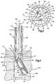
- FIG. 1is a fragmentary pictorial illustration depicting the relationship between an anchor constructed in accordance with one of the features of the present invention and a suture;
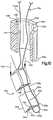
- FIG. 2is a fragmentary sectional view, illustrating a method in accordance with another feature of the invention and by which the anchor of FIG. 1 is moved into body tissue;
- FIG. 3is an enlarged sectional view, taken generally along the line 3 — 3 of FIG. 2, illustrating the relationship of the anchor to a tubular guide member and to a suture;
- FIG. 4is a fragmentary sectional view, taken along the line 4 — 4 of FIG. 2, illustrating the manner in which force is concentrated against a trailing end portion of the anchor by a pusher member to promote rotational movement of the anchor relative to body tissue;
- FIG. 5is a fragmentary sectional view, generally similar to FIG. 4, illustrating the manner in which the suture is tensioned to urge a corner portion of the anchor into engagement with body tissue;
- FIG. 6is a fragmentary sectional view taken generally along the line 6 — 6 of FIG. 5, further illustrating the relationship between the corner portion of the anchor, the body tissue and the tubular guide member;
- FIG. 7is a schematicized fragmentary pictorial view illustrating the relationship of the anchor of FIG. 1 to an embodiment of the tubular guide member having a locating surface which positions the anchor in a desired orientation relative to the tubular guide member;
- FIG. 8is a fragmentary cross-sectional view illustrating the construction of a pusher member used with the tubular guide member of FIG. 7;
- FIG. 9is an end view, taken generally along the line 9 — 9 of FIG. 8, further illustrating the construction of the pusher member
- FIG. 10is a schematicized cross-sectional view, illustrating the relationship of the anchor to the tubular guide member of FIG. 7 as the anchor moves out of the tubular guide member into body tissue;
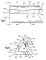
- FIG. 11is a side elevational view of an embodiment of the anchor of FIG. 1 having a groove to receive the suture;
- FIG. 12is an end view, taken generally along the line 12 — 12 of FIG. 11, further illustrating the construction of the groove and the relationship of the suture to the groove;
- FIG. 13is a fragmentary sectional view, generally similar to FIG. 2, illustrating the manner in which a suture extends through a plurality of anchors and the plurality of anchors are moved through a tubular member into body tissue;
- FIG. 14is a fragmentary sectional view, generally similar to FIG. 13, illustrating the manner in which a leading anchor of the plurality of anchors is rotated relative to a trailing anchor as the leading anchor moves out of the tubular member;
- FIG. 15is a fragmentary sectional view, generally similar to FIG. 14, illustrating the manner in which the trailing anchor moves out of the tubular member;
- FIG. 16is a fragmentary sectional view, generally similar to FIG. 15, illustrating the manner in which the leading and trailing anchors are urged into engagement with body tissue by tensioning of the suture;
- FIG. 17is a fragmentary sectional view, generally similar to FIG. 13, illustrating the manner in which a plurality of anchors cooperate with a tubular guide member having the same construction as the tubular guide member of FIG. 7;
- FIG. 18is an enlarged sectional view, generally similar to FIG. 3, illustrating the manner in which an anchor engages longitudinally extending grooves inside a tubular guide member;
- FIG. 19is an enlarged sectional view illustrating the relationship between a pair of anchors which are interconnected by a connector section.
- FIG. 20is a schematicized illustration depicting the manner in which the connector section is resiliently deformed by tensioning the suture to urge the anchors into engagement with body tissue in a manner similar to that illustrated in FIG. 16 .
- An anchor 10constructed in accordance with one of the features of the present invention may be used to secure a suture 12 in hard or soft body tissue.
- the anchor 10has a tubular wall 13 with an outer side 14 and an inner side 16 .
- the inner side 16defines a passage 18 which extends through the anchor 10 .
- the outer side 14 of the tubular wall 13has a polygonal cross-sectional configuration.
- the outer side 14 of the anchor 10includes a plurality of longitudinally extending outer corner portions 22 , 24 , and 26 .
- the outer corner portions 22 , 24 and 26are linear and interconnect a plurality of flat rectangular outer side surface areas 28 , 30 , and 32 .
- the tubular wall 13has an equilateral triangular cross-sectional configuration and forms a hollow prism. Therefore, the angles between the outer side surface areas 28 , 30 and 32 at each of the corner portions 22 , 24 and 26 is the same, that is, an angle of 120°. It should be understood that the outer side 14 of the anchor 10 could have a different configuration if desired.
- the outer side 14 of the anchor 10could have a cross-sectional configuration corresponding to the configuration of a segment of a circle.
- An anchor 10 with an outside surface with such a configurationwould have a pair of flat rectangular outer side surface areas. These surface areas would be interconnected by a corner portion. An arcuate surface area would extend between the flat outer side surface areas at a location opposite from the corner portion.
- the inner side 16 of the anchor 10has a polygonal cross-sectional configuration which corresponds to and is aligned with the polygonal outer side 14 of the anchor.
- the inner side 16 of the anchor 10defines open ends of the passage 18 which extends through the anchor.
- the inner side 16 of the anchorhas longitudinally extending inner corner portions 40 , 42 , and 44 .
- the inner corner portions 40 , 42 and 44are linear and are aligned with and extend parallel to the outer corner portions 22 , 24 , and 26 and to a longitudinal central axis of the anchor 10 .
- the inner side 16 of the anchor 10includes flat rectangular inner side surface areas 48 , 50 , and 52 which are interconnected by the inner corner portions 40 , 42 and 44 .
- the inner side surface areas 48 , 50 and 52extend parallel to and are spaced equal distances from the outer side surface areas 28 , 30 and 32 .
- the inner side 16has a triangular cross-sectional configuration and is aligned with the outer side 14 .
- the inner side 16has a longitudinal central axis which is coincident with a longitudinal central axis of the outer side 14 .
- the inner side 16 and outer side 14could have different configurations.
- the inner side 16could be formed with a cross-sectional configuration which corresponds to the configuration of a circle or a segment of a circle.
- the inner side 16could be formed as an almost complete cylinder with a radially extending corner portion which has a circumferential extent of, for example, 40° of the inner side.
- the tubular wall 13has three side walls 56 , 58 and 60 which are of the same size.
- the side walls 56 , 58 and 60form rectangular sections of the tubular wall 13 .
- the side walls 56 , 58 and 60could have a different configuration and that a greater or lesser number of side walls could be provided if desired.
- the anchorhad the configuration illustrated in FIG. 1 and was formed of stainless steel to ASTM designation F-138-86 specification.
- This specific embodiment of the anchor 10had a length of 3.10 millimeters.
- Each of the rectangular side walls 56 , 58 and 60had a width of 1.83 millimeters.
- the side walls 56 , 58 and 60had a thickness of 0.5 millimeters.
- the outer corner portions 22 , 24 and 26had a radius of 0.3 millimeters and the inner corner portions 40 , 42 and 44 had a radius of 0.15 millimeters.
- the anchor 10was also formed of stainless steel having an ASTM designation F-138-86 specification.
- This embodiment of the anchorhad a length of 7.2 millimeters.
- Each of the rectangular side walls 56 , 58 and 60had a width of 1.83 millimeters.
- the side wallshad a thickness of 0.5 millimeters.
- Both of the specific foregoing examples of the anchor 10had the hollow prism-shaped configuration illustrated in FIG. 1 .
- the anchor 10could be made with dimensions which are different than the specific dimensions set forth above. However, it is believed that it may be advantageous to make the anchor 10 with a length of from 2 to 8 millimeters and a width of 1.0 to 2.5 millimeters. Of course, the specific dimensions of the anchor 10 can be varied depending upon the environment in which the anchor is to be utilized to secure a suture 12 .
- the anchor 10is installed in body tissue in an orientation in which one of the outer corner portions 22 , 24 or 26 is embedded in body tissue by force applied against an adjacent inner corner portion 40 , 42 or 44 by the suture 12 .
- Force applied by the suture 12 against one of the inner corner portions 22 , 24 or 26 of the anchor 10presses the flat outer side surface areas which are interconnected by the embedded corner portion against the body tissue.
- the suture 12applies force against the inner corner portion 40
- the outer corner portion 22becomes embedded in the body tissue and the flat outer side surface areas 28 and 32 are pressed against the body tissue.
- the outer corner portions which are spaced from the embedded outer corner portion 22 , 24 or 26cooperate with the body tissue to stabilize the anchor 10 and hold it against sidewise movement.
- Parallel flat end surfaces 66 and 68 on the anchor 10extend perpendicular to the outer side surfaces 28 , 30 and 32 and cooperate with the body tissue to retain the anchor against axial movement relative to the body tissue.
- the cooperation between the outer corner portions 22 , 24 and 26 and outer side surfaces 28 , 30 and 32 with the body tissuesecurely retains the anchor 10 in place in the body tissue.
- the anchor 10When the anchor 10 is to be installed in human body tissue, the anchor may be pushed directly into the body tissue or into a recess may be formed in the body tissue to receive the anchor.
- the anchor 10may be installed in either hard or soft body tissue.
- the anchor 10is to be installed in bone 72 in a human body.
- the bone 72includes a compact outer layer 74 and a more porous cancellous tissue 76 which is surrounded by the compact outer layer.
- a cylindrical recess or cavity 78may be formed in the bone tissue to receive the anchor 10 in the manner illustrated in FIG. 2 . It should be understood that the anchor 10 may be used with soft tissue rather than the hard tissue of the bone 72 . It should also be understood that, if desired, the formation of the recess or cavity 78 may be omitted.
- a tubular guide member 82(FIGS. 2-6) is inserted into the recess 78 (FIG. 2 ).
- the illustrated guide member 82is cylindrical and is inserted through a circular opening 84 to the recess 78 .
- the guide member 82is inserted through the compact outer layer 74 of bone tissue.
- a circular open inner end 86 of the guide member 82is disposed immediately below (as viewed in FIG. 2) the inner side of the compact outer layer 74 of bone tissue 72 .
- the tubular guide member 82has a cylindrical outer side surface 88 with a diameter which is substantially the same as the diameter of the cylindrical recess 78 and the circular opening 84 to the recess. Therefore, the bone tissue 82 firmly engages the outer side surface 88 of the guide member 72 to hold the guide member in position relative to the recess 78 .
- the recess 78extends inward past the lower (as viewed in FIG. 2) end 86 of the guide member 82 for a distance which is at least as great as the length of the anchor 10 , that is at least as great as the distance from the end surface 66 to the end surface 68 (FIG. 1) of the anchor 10 .
- the tubular guide member 82has a cylindrical inner side surface 92 (FIG. 3 ).
- the anchoris positioned in the guide member 82 with the end surface 66 on the anchor leading (FIG. 2) and the end surface 68 on the anchor 10 trailing.
- the outer corner portions 22 , 24 and 26 of the anchor 10are disposed in engagement with the inner side surface 92 (FIG. 3) of the guide member 82 at equally spaced increments (approximately 120°) about the inner side surface of the guide member.
- a longitudinal central axis of the anchor 10is coincident with a longitudinal central axis of the guide member 82 .
- the outer side surface areas 28 , 30 and 32 (FIG. 3) of the anchor 10are spaced from the inner side surface 92 of the guide member 82 .
- the outer side surface areas 28 , 30 and 32extend parallel to a longitudinal central axis of the guide member 82 .
- the outer side surface areas 28 , 30 and 32 on the anchor 10cooperate with the inner side surface area 92 on the guide member 82 to form a plurality, of channels 96 , 98 and 100 between the anchor 10 and the inner side surface 92 of the guide member 82 .
- the channels 96 , 98 and 100extend axially along the length of the anchor 10 .
- a portion 104 (FIG. 2) of the suture 12extends downward (as viewed in FIG. 2) through the upper portion of the guide member 82 into the passage 18 in the anchor 10 .
- a relatively short portion 106 of the suture 12extends across the leading end surface 66 of the anchor 10 .
- a second relatively long portion 108 of the suture 12extends upward along the outer side surface area 32 of the anchor 10 through the channel 100 .
- the relatively long portions 104 and 108 of the suture 12extend from the guide member 82 to a location offset to one side of the recess 78 in the bone tissue 72 .
- a hollow cylindrical pusher member 112(FIG. 2) is inserted into the guide member 82 through an open upper or outer end of the guide member.
- the pusher member 112extends through the open upper or outer end of the guide member 82 .
- the distance to which the pusher member 112 extends into telescopic engagement with the guide member 82can be varied by moving the pusher member axially relative to the guide member.
- the pusher member 112could have a configuration which is different than the cylindrical configuration of the guide member 82 , it is preferred to utilize a pusher member having the same configuration as the guide member.
- the suture 12extends through a cylindrical passage 114 formed in the tubular pusher member 112 .
- the portion 104 of the suture 12extends into the pusher member 112 from a location offset to one side of the recess 78 in the bone tissue 72 .
- the portion 104 of the suture 12extends through the passage 114 in the pusher member 112 to the passage 18 in the anchor 10 .
- the portion 106 of the suture 12extends across the leading end 66 of the anchor 10 .
- the portion 108 of the suture 12extends upward through the channel 100 along the outer side of the anchor 10 (FIGS. 2 and 3 ).
- the portion 108 of the suture 12then extends through an open lower or inner end portion 116 (FIG. 2) of the pusher member 112 into the passage 114 in the tubular pusher member.
- the portion 108 of the suture 12then extends from the open upper end of the pusher member to a location which is offset to one side of the recess 78 .
- a surgeoncan manually grip the suture 12 adjacent to an open upper end of the pusher member 112 .
- the pusher member 112has a cylindrical outer side surface 122 which telescopically engages the cylindrical inner side surface 92 of the guide member 82 .
- the cylindrical outer side surface 122 of the pusher member 112has a diameter which is just slightly less than the diameter of the cylindrical inner side surface 92 of the guide member 82 . Therefore, the pusher member 112 can slide freely along the inner side surface 92 of the guide member 82 while the guide member holds the inner side surface of the cylindrical pusher member in alignment with the longitudinal central axis of the anchor 10 (FIG. 2 ).
- the cylindrical inner side surface 92 of the guide member 82engages the outer corner portions 22 , 24 and 26 of the anchor 10 to guide movement of the anchor and engages the outer cylindrical side surface 122 of the pusher member 112 to guide movement of the pusher member.
- the open end portion 116 of the pusher member 112is axially tapered to enable the pusher member 112 to apply a concentrated force against the trailing end surface 68 (FIG. 2) of the anchor 10 .
- the pusher member 112has a lower (as viewed in FIG. 2) end surface 126 which is skewed at an acute angle to a longitudinal central axis of the pusher member (FIG. 4 ).
- the pusher member 112has a flat end surface 128 which engages the trailing end surface 68 of the anchor 10 .
- the flat end surface 128has a length and width which enables it to engage the trailing end surface 68 of the anchor regardless of the orientation of the pusher member 112 relative to the trailing end surface 68 of the anchor. This enables the pusher member 112 to engage the trailing end surface 68 of the anchor at a location adjacent to one of the outer corner portions 22 , 24 or 26 (FIG. 2) of the anchor and/or to engage the anchor at a location adjacent to one of the outer side surface areas 28 , 30 or 32 of the anchor.
- the tapered configuration of the open end portion 116 of the pusher member 112results in the pusher member applying a concentrated force against the trailing end surface 68 of the anchor at a location which is offset from the central axis of the anchor. Since the force applied by the pusher member 112 to the trailing end surface 68 of the anchor is offset from the central axis of the anchor 10 , a torque is applied to the anchor which tends to rotate the anchor about an axis extending through the location where the end portion 116 of the pusher member 112 engages the trailing end surface 68 of the anchor.
- the outer corner portions 22 , 24 and 26 of the anchor memberengage the cylindrical inner side surface 92 of the guide member 82 to retain the anchor against rotational movement under the influence of the concentrated force applied against the trailing end surface 68 of the anchor by the pusher member 112 .
- the cylindrical inner side surface 92 of the guide member 82cooperates with the anchor 10 to retain the longitudinal central axis of the anchor 10 coincident with the longitudinal central axis of the guide member.
- cylindrical inner side surface 92 of the guide member 82cooperates with a cylindrical outer side surface 132 of the pusher member 112 to retain the pusher member in an orientation in which the longitudinal central axis of the pusher member is coincident with the longitudinal central axis of the guide member 82 .
- the guide member 82 and the pusher member 112both have cylindrical configurations. However, it is contemplated that the pusher member 112 and guide member 82 could have different configurations. For example, the guide member 82 and the pusher member 112 could both have triangular cross-sectional configurations. If desired, the guide member 82 could have a circular cross-sectional configuration and the pusher member 112 could have a triangular cross-sectional configuration.
- the suture 12When the anchor 10 is to be installed in body tissue, which may be either hard or soft tissue, the suture 12 is inserted through the passage 18 (FIG. 2) in the anchor 10 .
- the relatively long portion 104 of the suture 12extends through the passage 18 to the portion 106 of the suture.
- the portion 106 of the sutureextends across the end surface 66 of the anchor.
- the portion 108 of the sutureextends along the outer side 13 of the anchor 10 . In FIG. 2, the portion 108 of the suture 12 extends along the outer side surface area 32 . However, the portion 108 of the suture 12 could extend along any one of the outer side surface areas 28 , 30 or 32 .
- the anchoris inserted into the guide member 82 .
- the outer corner portions 22 , 24 and 26 (FIG. 3) of the anchorengage the inner side surface 92 of the guide member 82 to position the anchor relative to the guide member.
- the portion 108 of the suture 12extends through the channel 100 formed between the outer side surface area 32 on the anchor 10 and the inner side surface 92 of the guide member 82 .
- the guide member 82retains the anchor 10 in an orientation in which a longitudinal central axis of the anchor is coincident with a longitudinal central axis of the guide member.
- the suture 12is inserted through the open ended passage 114 (FIG. 2) in the pusher member 112 .
- the pusher member 112is inserted into the guide member. The open leading end portion 116 of the pusher member 112 is moved into engagement with the trailing end surface 68 of the anchor 10 .
- the pusher member 112is pressed against the trailing end surface 68 of the anchor 10 to move the anchor through the guide member 82 toward the recess 78 in the bone 72 .
- the anchor 10 and pusher member 112may rotate relative to each other and to the guide member 82 about their coincident central axes.
- the inner side surface 92 of the guide member 82engages the corner portions 22 , 24 , and 26 of the anchor 10 to retain the anchor against rotational movement about an axis extending transversely to and offset from the longitudinal central axis of the anchor.
- the corner portions 22 , 24 and 26 on the anchor 10slide along the inner side surface 92 of the guide member 82 to maintain the longitudinal central axis of the anchor coincident with the longitudinal central axis of the guide member.
- a concentrated forceis applied against the trailing end surface 68 of the anchor by the tapered end portion 116 of the pusher member 112 .
- the pusher member 112applies the concentrated force against the anchor 10 at a location which is offset to one side of the longitudinal central axis of the anchor 10 .
- the flat end surface 128 on the tapered end portion 116 of the pusher member 112engages the anchor 10 at a trailing end of one of the corner portions 22 , 24 or 26 and/or a trailing end of one of the sidewalls 56 , 58 or 60 .
- the tapered end portion 116 of the pusher member 112has a radial thickness which is sufficient to enable the tapered end portion to span one of the channels 96 , 98 or 100 (FIG. 3) to engage the trailing end of a sidewall 56 , 58 or 60 at a location spaced from the corner portions 22 , 24 and 26 of the anchor 10 .
- the anchor 10As the pusher member 112 moves downward (as viewed in FIG. 2) relative to the guide member 82 , the anchor 10 is pushed downward in the guide member. As this occurs the anchor 10 pulls the suture downward. Thus, force is transmitted from the leading end surface 66 of the anchor 10 to the portion 106 of the suture 12 to pull the suture into the pusher member 112 and guide member 82 .
- the leading end of the anchor and the portion 106 of the suture 12emerge from the open lower end 86 of the guide member 82 into the recess 78 .
- the suture 12is tensioned to apply force against the leading end surface 66 of the anchor.
- the surgeonpulls on the portions 104 and 108 of the suture 12 to tension the suture. This force pulls the anchor upward (as viewed in FIG. 2) against the pusher member 112 .
- the sutureslides along one of the inner side surface areas 48 , 50 or 52 on the anchor into one of the inner corner portions 40 , 42 or 44 .
- Thistends to rotate the anchor about its longitudinal central axis relative to the pusher member 112 to move one of the side walls 56 , 58 or 60 on the anchor into alignment with the tapered end portion 116 of the pusher member 112 .
- the force applied by the tapered end portion 116 of the pusher member 112becomes concentrated at the trailing end portion of one of the side walls 56 , 58 or 60 of the anchor.
- the anchor 10rotates about its central axis from the position shown in FIG. 2 to the position shown in FIG. 4 .
- the surface 126 on the tapered leading end portion 116 of the pusher member 112engages the trailing end of the side wall 58 (FIG. 1) of the anchor 10 .
- the torque applied to the anchor 10 by the pusher member 112tends to rotate the anchor in a clockwise direction, as indicated by the arrow 140 in FIG. 4 .
- the tension in the suture 12applies force against the leading end surface 66 of the anchor.
- the force applied against the leading end 66 of the anchor 10 by the suture 12pulls the trailing end 68 of the anchor back or upward (as viewed in FIG. 4) toward the tapered leading end portion 116 of the pusher member 112 . Therefore, the tension in the suture 12 tends to further rotate the anchor 10 in a counterclockwise direction (as viewed in FIG. 4 ), in the manner indicated schematically by the arrow 140 .
- the inner corner portion 40 of the anchor 10holds the suture 12 against sidewise movement relative to the anchor and concentrates the force applied by the suture to the anchor at the inner corner portion of the anchor.
- the anchorUnder the combined influence of the concentrated force applied against the trailing end surface 68 of the anchor 10 by the pusher member 112 and the force applied against the inner corner portion 40 of the anchor adjacent to the leading end surface 66 by the suture 12 , the anchor is rotated into the cancellous bone tissue 76 , in the manner indicated schematically by the arrow 140 in FIG. 4 .
- the anchor 10is rotated about an axis which extends perpendicular to and is offset from the central axis of the guide member 82 .
- the axis about which the anchor 10 rotatesextends through the location where the leading end surface 128 on the pusher member 112 engages the trailing end surface 68 on the anchor 10 .
- the pusher member 112continues to move axially downward (as viewed in FIG. 4) in the guide member 82 into the recess 78 .
- the anchor 10continues to rotate about the axis extending through the location where the end surface 128 on the pusher member 112 engages the end surface 68 on the anchor 10 until the surface 68 on the anchor moves into abutting engagement with the sloping end surface 126 on the pusher member 112 .
- the central axis of the anchorextends perpendicular to the sloping end surface 126 and is skewed at an angle of 45° to the central axis of the guide member 82 .
- the pusher member 112is then withdrawn into the guide member 82 .
- the force applied by the suture 12 against the leading end 66 of the anchor 10continues in counterclockwise rotation of the anchor.
- the force applied against the leading end portion 66 of the anchor by the suture 12presses the trailing end portion 68 of the anchor against the left (as viewed in FIGS. 4 and 5) side surface of the recess 78 .
- the anchor 10is first moved toward the right (as viewed in FIG. 4) of the central axis of guide member 82 under the combined influence of force applied against the anchor by the pusher member 112 and the suture 12 .
- the pusher member 112is then slowly withdrawn and, simultaneously therewith, the anchor 10 is moved toward the right (as viewed in FIGS. 4 and 5) under the influence of force applied against the anchor by tension in the suture 12 .
- the suture 12is tensioned by the surgeon when he or she manually pulls on the suture.
- the force on the anchor 10causes it to move to the substantially horizontal orientation shown in FIGS. 5 and 6.
- the longitudinal central axis of the anchor 10 and the outer corner portions 22 , 24 and 26 of the anchorextend perpendicular to the coincident longitudinal central axes of the guide member 82 and pusher member 112 .
- the tension force in the suture 12pulls the outer corner portion 22 of the anchor 10 upward toward the lower end of the guide member 82 .
- the outer corner portion 22 of the anchor 10becomes embedded in the relatively soft cancellous bone tissue 76 (FIG. 6 ).
- the flat outer side surface areas 28 and 32press against the cancellous bone tissue to stabilize the anchor 10 .
- the outer corner portions 24 and 26 opposite from the corner portion 22cooperate with the cancellous bone tissue 76 to further stabilize the anchor and retain the anchor 10 against movement relative to the body tissue 72 .
- the polygonal configuration of the anchor 10results in the anchor being retained against movement relative to the body tissue 72 .
- the outer corner portions 22 , 24 and 26 of the anchor 10become embedded in the body tissue 72 .
- the flat outer side surface areas 28 and 32 of the anchorare pressed against the body tissue to further stabilize the anchor.
- the body tissuetends to grow into the recess 78 and the space caused by moving the anchor 10 from the position shown in FIG. 2 through the position shown in FIG. 4 to the position shown in FIG. 5 . As this occurs, the body tissue grows into engagement with the flat outer side surface area 30 of the anchor to further stabilize the anchor.
- the anchor 10is very stable in the body tissue 72 , the anchor can be removed from the body tissue in the same manner as is disclosed in the aforementioned U.S. patent application Ser. No. 08/062,295 filed May 14, 1993 of which this application is a continuation-in-part.
- the anchor 10is randomly oriented relative to the guide member 82 .
- the force applied against the anchor by tensioning the suture 12results in the suture moving along an inner side surface area 48 , 50 or 52 of the anchor into engagement with one of the inner corner portions 40 , 42 and 44 .
- the anchormoves relative to the pusher member 112 to an orientation in which the tapered end portion 116 of the pusher member 112 applies a concentrated force against a portion of the anchor opposite from the inner corner portion engaged by the suture 12 .
- the pusher member 112applies a concentrated force against the side wall 58 adjacent to the outer corner portions 24 and 26 .
- the tubular guide memberis constructed so as to retain the anchor in a selected orientation relative to the guide member as the anchor moves axially through the guide member.
- the pusher memberis constructed so as to apply a concentrated force against a selected portion of the anchor. Since the embodiment of the invention illustrated in FIGS. 7-10 is generally similar to the embodiment of the invention illustrated in FIGS. 1-6, similar numerals will be utilized to designate similar components, the suffix letter “a” being associated with the numerals of FIGS. 7-10 to avoid confusion.
- a tubular guide member 82 a(FIG. 7) has a cylindrical outer side surface 88 a and a cylindrical inner side surface 92 a .
- the guide member 82 ahas a linear locating rib 142 which orients the anchor 10 a in the guide member 82 a .
- the locating rib 142extends axially along the inner side 92 a of the guide member 82 a for the entire length of the guide member.
- a longitudinal central axis of the locating rib 142extends parallel to a longitudinal central axis of the guide member 82 a.
- the locating rib 142has a flat inwardly facing locating surface 144 .
- the flat locating surface 144is disposed in a plane which forms a chord to the cylindrical inner side surface 92 a of the guide member 82 a .
- the plane in which the locating surface 144 is disposedextends parallel to the longitudinal central axis of the guide member 82 a .
- the locating surface 144has an axial extent which is the same as the axial extent of the guide members 82 a.
- the locating surface 144engages the flat outer side surface area 30 a on the anchor 10 a to position the anchor in a predetermined orientation relative to the guide member 82 a .
- the corner portion 22 a of the anchor 10 ais disposed diametrically across from the locating surface 144 .
- the anchor 10 acould be positioned relative to the tubular guide member 82 a with the flat locating surface 144 in abutting engagement with any one of the flat outer side surface areas 28 a , 30 a or 32 a on the anchor.
- the corner portions 22 a , 24 a and 26 a (FIG. 7) of the anchor 10 aengage the cylindrical inner side surface 92 a of the guide member 82 a to hold the anchor 10 a in alignment with a longitudinal central axis of the guide member 82 a .
- the locating surface 144engages the flat outer side surface area 30 a on the anchor 10 a to hold the anchor in a predetermined orientation relative to the longitudinal central axis of the guide member 82 a .
- the locating surface 144engages the flat outer side surface 30 a on the anchor 10 a to prevent rotation of the anchor about its longitudinal central axis relative to the guide member 82 a .
- the longitudinal central axis of the anchor 10 ais coincident with the longitudinal central axis of the guide member 82 a.
- the location of the anchor 10 a relative to the body tissue into which it is to be insertedcan be selected by a surgeon before inserting the anchor.
- the outer corner portion 22 a of the anchor 10 ais diametrically across the guide member 82 a from the locating surface 144 .
- the corner portion 22 a of the anchor 10 ahas a longitudinal central axis which is located in a plane which contains the longitudinal central axis of the locating rib 142 . Therefore, by selecting the orientation of the locating rib 142 relative to the body tissue, the surgeon can select the orientation of the outer corner portion 22 a of the anchor relative to the body tissue.
- the longitudinal central axis of the corner portion 22 a of anchor 10 ais still disposed in the plane containing the parallel longitudinal central axes of the guide member 82 a and the locating rib 142 .
- the longitudinal central axis of the anchor 10 ais also disposed in the plane containing the longitudinal central axes of the guide member 82 a and the locating rib 142 .
- the longitudinal central axes of the corner portion 22 a and anchor 10 aextend perpendicular to the parallel longitudinal central axes of the guide member 82 a and locating rib 142 .
- a pusher member 112 a(FIGS. 8 and 9) cooperates with the guide member 82 a to apply force against the anchor 10 a at locations which are opposite from the outer corner portion 22 a and are adjacent to opposite longitudinally extending side surfaces 146 and 148 (FIG. 7) on the locating rib 142 .
- the side surfaces 146 and 148extend perpendicular to the locating surface 144 .
- the side surfaces 146 and 148extend parallel to each other and are spaced apart by a distance which is substantially less than the distance between the corner portions 24 a and 26 a of the anchor 10 a.
- the pusher member 112 ais a cylindrical tubular member having a tapered end portion 116 a (FIG. 8 ).
- the tubular pusher member 112 ahas a radially extending slot 150 (FIG. 9) which extends throughout the length of the pusher member and receives the locating rib 142 .
- Opposite side surfaces 151 and 152 of the slot 150extend parallel to each other and engage opposite side surfaces 146 and 148 on the locating rib 142 .
- the locating rib 142cooperates with the slot 150 to orient the pusher member 112 a relative to the guide member 82 a . Since the anchor 10 a is also oriented relative to the guide member 82 a by the locating rib 142 , the locating rib is effective to orient the pusher member 112 a relative to the anchor.
- the pusher member 112 ahas a tapered leading or lower (as viewed in FIG. 8) end surface 128 a which applies force against the anchor 10 a at locations adjacent to opposite sides of the locating rib 142 in the tubular guide member 82 a .
- the manner in which the end surface 128 a on the pusher member 112 a applies force against the anchor 10 ais indicated schematically in FIG. 7 by the arrows 154 and 156 .
- the arrows 154 and 156extend parallel to the longitudinal central axis of the locating rib 142 and to the longitudinal central axis of the anchor 10 a.
- the pusher member force represented by the arrows 154 and 156is applied against the trailing end surface area 68 a on the side wall 58 a (FIG. 7) of the anchor 10 a opposite from the outer corner portion 22 a .
- the pusher member 112 aapplies a force which is concentrated against the same side wall 58 a of the anchor as is engaged by the locating surface 144 on the locating rib 142 .
- the tubular guide member 82 aWhen the anchor 10 a is to be installed in body tissue, the tubular guide member 82 a is positioned in a selected orientation relative to the body tissue. Thus, the open lower end 96 a (FIG. 10) of the guide member 82 a is inserted into a recess in the body tissue, in the manner illustrated in FIG. 2 for the guide member 82 , with the locating rib 142 at a location where it is desired to have the outer corner portion 22 a of the anchor 10 a embedded in the body tissue.
- the suture 12 a(FIG. 10) is inserted through the central passage 18 a in the anchor 10 a .
- the portion 104 a of the suture 12 aextends through the passage 18 a in the anchor 10 a and the portion 108 a of the suture 12 a extends along the outer side surface 32 a of the anchor.
- the sutureis also inserted through the central passage 114 a (FIG. 8) in the pusher member 112 a.
- the anchor 10 ais then positioned in the guide member 82 a with the flat outer side surface area 30 a (FIG. 7) on the anchor in abutting engagement with the flat locating surface 144 on the locating rib 142 .
- the portion 108 a of the suturewill extend through the channel 100 a formed between the inner side surface 92 a of the guide member 82 a and the outer side of the anchor 10 a.
- the pusher member 112 ais then inserted into the tubular guide member 82 a with the portions 104 a and 108 a of the suture 12 a extending through the cylindrical passage 114 a in the tubular pusher member.
- the locating rib 142extends radially through the slot 150 formed in the pusher member 112 a .
- the side surfaces 151 and 152 of the slot 150(FIG. 9) engage opposite side surfaces 146 and 148 on the locating rib 142 ). Engagement of the locating rib 142 with the slot 150 in the pusher member 112 a orients the pusher member 112 a relative to both the anchor 10 a and the guide member 82 a.
- the lower or leading end surface 128 a (FIG. 8) on the pusher member 112 aengages the upper end surface of the side wall 58 a (FIG. 7) of the anchor 10 a adjacent to opposite sides of the locating rib 142 .
- the end surface 128 a on the pusher member 112 aapplies force against the trailing end surface 68 a of the anchor 10 a at the side wall 58 a , in the manner indicated by the arrows 154 and 156 in FIG. 7 .
- the force applied against the trailing end surface 68 a of the anchor 10 a by the pusher member 112 amoves the anchor axially downward (as viewed in FIG. 7) through the guide member 82 a until a leading end surface 66 a (FIG. 10) on the anchor emerges from the open lower (as viewed in FIG. 10) end 92 a of the guide member 82 a .
- both the anchor and the pusher member 112 aare maintained in a predetermined orientation relative to the guide member by the locating rib 142 .
- the locating rib 142cooperates with the pusher member 112 a and the anchor 10 a to retain them against rotation relative to each other about the central axis of the guide member 82 a.
- the locating rib 142positions the anchor relative to the guide member 82 a .
- the guide member 82 acould be formed with a configuration corresponding to the configuration of a segment of a circle. If this was done, the portion 108 a of the suture 12 a would be disposed adjacent to the arcuate portion of the guide member while the opposite outer corner portion of the anchor would be engaged by the apex of the guide member.
- the guide membercould have a polygonal cross-sectional configuration corresponding to the polygonal cross-sectional configuration of the anchor. If this is done, a groove in the guide member could be used as a channel to receive the portion 108 a of the suture 12 a.
- FIGS. 11 and 12it may be desired to protect the suture 12 from engagement with surfaces in the environment in which the anchor is used.
- groovesare provided to receive the suture to protect the suture. Since the embodiment of the anchor illustrated in FIGS. 11 and 12 is generally similar to the embodiment of the invention illustrated in FIGS. 1-6, similar numerals will be utilized to designate similar components, the suffix letter “b” being associated with the numerals of FIGS. 11 and 12 to avoid confusion.
- An anchor 10 bhas outer corner portions 22 b , 24 b and 26 b which interconnect flat outer side surface areas 28 b , 30 b and 32 b .
- a central passage 18 bextends through the anchor.
- the anchor 10 bhas the same configuration as the anchor 10 of FIG. 1 .
- the anchor 10 bhas a groove 162 (FIG. 11) in which the suture 12 b is received.
- the groove 162has a longitudinally extending main portion 164 which is disposed inwardly from the flat outer side surface 32 b of the anchor 10 b .
- the main portion 164 of the groove 162has a flat bottom surface 166 which extends parallel to the flat outer side surface area 32 b and extends between axially opposite ends of the anchor 10 b .
- the main portion 164 of the groove 162receives the portion 108 b of the suture 12 b which extends along the outside of the anchor.
- the main portion 164 of the groove 162has a flat longitudinally extending side surface 170 which is disposed in a central portion of the flat outer side surface 32 b and a flat longitudinally extending side surface 172 which is disposed in a central portion of the outer corner portion 22 b (FIG. 12 ).
- Thisenables the portion 10 b (FIG. 11) of the suture 12 b to move from a position adjacent to the central portion of the flat outer side surface 32 b to the outer corner portion 22 b as the inner portion of the suture moves into engagement with the inner corner portion 40 b (FIG. 12) of the anchor 10 b .
- the anchor 106is rotated and moved into position relative to the end of the guide member in the manner shown in FIGS.
- the portion 108 b of the suture 12 bwill move sidewardly, that is in a direction transverse to the longitudinal central axis of the main portion 164 of the groove 162 , into engagement with the longitudinally extending side surface 172 of the groove. This occurs as the portion of the suture which extends through the passage 18 b in the anchor 10 b moves into engagement with the inner corner portion 40 b of the anchor.
- the groove 162has an end portion 176 which extends transversely to the main portion 164 of the groove 162 and extends across the end surface 66 b of the anchor 10 b .
- the end portion 176 of the groove 162extends from a central portion of an end of the side wall 60 b to the inner and outer corner portions 40 b and 22 b .
- the end portion 176 of the groove 162receives the portion 106 b of the suture 12 b to protect the suture.
- the portion 106 b of the suturecan move to a location extending between the inner corner portion 40 b and the outer corner portion 22 b as the anchor is moved from the orientation shown in FIG. 4 to the orientation shown in FIG. 5 for the anchor 10 .
- groove 162has been illustrated herein as having both the main portion 164 and the end portion 176 , it is contemplated that the groove 162 could have either just the main portion 164 or the end portion 176 if desired. It is also contemplated that the groove 162 could have a configuration other than the configuration illustrated herein.
- a single anchor 10is used to secure the suture 12 in body tissue.
- a plurality of anchorsare used to secure a suture in body tissue. Since the embodiment of the invention illustrated in FIGS. 13-16 is generally similar to the embodiment of the invention illustrated in FIGS. 1-6, similar numerals will be utilized to designate similar components, the suffix letter “c” being associated with the numerals of FIGS. 13-16 to avoid confusion.
- a pair of anchors 182 and 184are used to secure a suture 12 c in body tissue.
- the anchors 182 and 184both have the same general construction as the anchor 10 of FIGS. 1-6.
- the trailing anchor 182has a tapered leading end portion 186 .
- the anchors 182 and 184could have a construction which is different from the construction of the anchor 10 .
- the tapered leading end portion 186 of the trailing anchor 182extends from an outer corner portion 22 c of the anchor 182 to an outer side surface 30 c on a side wall 58 c and to the corner portions opposite from the corner portion 22 c of the anchor 182 .
- the outer side surface area 30 chas a flat rectangular configuration.
- the tapered leading end portion 186 of the anchor 182includes a flat leading end surface 66 c which is disposed in a plane which is skewed at an acute angle to a trailing end surface 68 c .
- the construction of the anchor 182is the same as the construction of the anchor 10 of FIGS. 1-6.
- the leading anchor 184has the same construction as the anchor 10 of FIGS. 1-6. Thus, the leading anchor 184 has a leading end surface 66 c which is parallel to the trailing end surface 68 c . The leading and trailing end surfaces 66 c and 68 c of the anchor 184 extend perpendicular to a longitudinal central axis of the suture.
- anchors 182 and 184could have a configuration which is different than the configuration of the anchor 10 .
- the anchors 182 and 184could have a cylindrical configuration or any of the other anchor configurations disclosed in the aforementioned U.S. patent application Ser. No. 08/062,295 filed May 14, 1993 of which this application is a continuation-in-part.
- the anchor corresponding to the anchor 182 and having any one of these constructionsmay be provided with a tapered leading end portion.
- leading anchor 184could be tapered in a manner similar to the tapered leading end portion 186 of the trailing anchor 182 . If the trailing end portion of the anchor 184 is tapered, the leading end portion of the anchor 182 could extend perpendicular to the central axis of the anchor 182 or could be tapered in a manner similar to that shown in FIG. 13 .
- a cylindrical recess 78 cmay be formed in the body tissue.
- a tubular cylindrical guide member 82 cis inserted into the recess 78 c in the manner illustrated in FIG. 13 .
- the tubular guide member 82 chas the same construction as the guide member 82 of FIGS. 2-6, a guide member having a different construction could be used if desired.
- the suture 12 cis inserted through central passages 18 c in the anchors 182 and 184 . This results in the two anchors 182 and 184 being strung together on the suture 12 c .
- a portion 104 c (FIG. 13) of the suture 12 cextends through the central passage 18 c in the anchor 182 and through the central passage 18 c in the anchor 184 .
- a portion 106 c of the suture 12 cextends across the leading end surface 66 c of the leading anchor 184 .
- a portion 108 c of the suture 12 cextends along the outside of the two anchors 182 and 184 .
- the anchors 182 and 184are positioned in the tubular guide member 82 c . Corner portions of the anchors 182 and 184 engage a cylindrical inner side surface 92 c of the guide member 82 c . Thus, the corner portions of the anchors 182 and 184 engage the inner side surface 92 c of the guide member 82 c in the same manner as in which the corner portions 22 , 24 and 26 of the anchor 10 engage the inner side surface 92 of the tubular guide member 82 (FIG. 3 ).
- the anchors 182 and 184are positioned in the cylindrical guide member 82 c with the corner portions of the anchors aligned with each other and with the anchors in a coaxial relationship with each other.
- the anchors 182 and 184are also positioned in the guide member 82 c with the anchors in a coaxial relationship with each other and with the guide member.
- a knife edge end 190 of the tapered leading end portion 186 of the anchor 182is disposed in engagement with the trailing end surface 68 c of the anchor 184 along the side wall 58 c of the anchor 184 .
- the knife edge end 190 of the tapered leading end portion 186 of the anchor 182has a configuration similar to the configuration of a cutting portion of a chisel.
- the knife edge end 190extends along the side wall 58 c of the anchor 182 between corner portions at opposite ends of the side wall, that is, between corner portions corresponding to the corner portions 24 and 26 (FIG. 3) of the anchor 10 .
- forceis transmitted from the trailing anchor 182 to the leading anchor 184 along the entire width of the trailing end surface of the side wall 58 c of the anchor 184 .
- a cylindrical tubular pusher member 112 cis inserted into the guide member 82 c and applies force to the trailing end surface 68 c of the trailing anchor 182 .
- the pusher member 112 chas a flat circular leading end surface 126 c which is disposed in a plane extending perpendicular to a longitudinal central axis of the pusher member 112 c .
- the pusher member 112 c of FIG. 13does not have a tapered open end portion in the same manner as does the pusher member 112 of FIGS. 2 and 4.
- the pusher member 112 ccould be provided with a tapered open end portion having a configuration similar to the configuration of the tapered open end portion 116 of the pusher member 112 (FIGS. 2 and 4 ).
- the circular leading end surface 126 c of the pusher member 112 cengages the trailing end surface 68 c of the trailing anchor 182 at each of the three corner portions of the anchor. This results in the trailing anchor 182 being pushed straight down (as viewed in FIG. 13) by the pusher member 112 c .
- the pusher member 112 cdoes not apply torque to the trailing anchor 182 . This is because the force applied to the trailing end surface 68 c of the anchor 182 by the pusher member 112 c is balanced about the central axis of the anchor.
- the trailing anchor 182is effective to apply torque to the leading anchor 184 . This is because force is transmitted from the trailing anchor 182 through the tapered leading end portion 186 of the trailing anchor 182 to the leading anchor 184 .
- the force transmitted from the trailing anchor 182 to the leading anchor 184is concentrated along the width of the side wall 58 c of the leading anchor by the knife edge end 190 of the trailing anchor. This concentrated force is offset from the longitudinal central axis of the leading anchor 184 . Therefore, the trailing anchor 182 applies torque to the leading anchor 184 tending to rotate the leading anchor in a counterclockwise direction, as viewed in FIG.
- leading anchor 184Since the three outer corner portions of the leading anchor 184 are disposed in engagement with the cylindrical inner side surface 92 c of the guide member 82 c , in the manner illustrated in FIG. 3 for the anchor 10 , the leading anchor 184 is restrained against rotational movement under the influence of torque transmitted from the trailing anchor 182 to the leading anchor 184 . Thus, the leading anchor 184 is moved straight downward (as viewed in FIG. 13) under the influence of the force transmitted from the trailing anchor 182 to the leading anchor. The leading end surface 66 c of the leading anchor 184 applies force against the portion 106 c of the suture 12 c to pull the suture downward in the guide member 82 c.
- the leading anchor 184moves through the open lower end portion 86 c of the guide member 82 c .
- the concentrated force applied against the trailing end surface 68 c of the leading anchor 184 by the tapered knife edge end portion 186 of the trailing anchor 182causes the leading anchor to rotate in a counterclockwise direction, in the manner indicated by the arrow 140 c in FIG. 14 .
- leading anchor 184rotating about an axis which extends through the location where the knife edge end 190 of the trailing anchor 182 engages the portion of the trailing end surface 68 c of the leading anchor 184 disposed on the trailing end of the side wall 58 c of the leading anchor 184 .
- the trailing anchorcontinues to move straight downward (as viewed in FIG. 14) along the tubular guide member 82 c .
- the leading anchor 184is rotated in a counterclockwise direction, in the manner indicated by the arrow 140 c in FIG. 14, the leading end 66 c of the leading anchor moves rightward into the relatively soft cancellous bone tissue 76 c .
- the outer corner portion 22 c of the anchor 184is leading.
- the wedge-shaped configuration of the outer corner portion 22 c of the leading anchor 184facilitates movement of the leading anchor 184 in the cancellous bone tissue.
- the suture 12is tensioned by pulling on the two portions 106 c and 108 c of the suture. This pulls the portion 106 c of the suture against the leading end surface 66 c of the leading anchor 184 .
- the force applied by the suture 12 c to the leading end surface 66 c of the leading anchor 184urges the leading anchor upward and toward the left (as viewed in FIG. 14) toward the tapered leading end portion 186 of the trailing anchor 182 .
- the counterclockwise (as viewed in FIG. 14) rotation of the leading anchor 184continues until the trailing end surface 68 c on the leading anchor engages the leading end surface 66 c on the trailing anchor 182 .
- the pusher member 112 cpushes the trailing end surface 68 c of the trailing anchor 182 out of the guide member 82 c .
- the outer corner portions of the trailing anchor 182move out of engagement with the cylindrical inner side surface 92 c of the guide member 82 c .
- Force transmitted from the suture 12 c through the leading anchor 184 to the trailing anchor 182causes the trailing anchor to rotate and move leftward toward the position shown in FIG. 15 .
- the leading anchor 184continues to rotate under the influence of the force applied against the leading anchor by the suture 12 c .
- the two anchors 182 and 184are rotated together through the position shown in FIG. 15 to the position shown in FIG. 16 .
- the outer corner portions 22 c of the anchorsengage the lower end surface 86 of the guide member 82 c and are embedded in the soft cancellous bone tissue.
- the force applied against the two anchors 182 and 184 by tensioning the suture 12 cpresses the leading end surface 66 c on the tapered leading end portion 186 of the trailing anchor 182 firmly against the trailing end surface 68 c on the anchor 184 .
- the flat outer major side surfaces on the anchors 182 and 184press against the soft cancellous bone tissue and the outer corner portions of the anchors 182 and 184 are engaged by the soft cancellous bone tissue to stabilize the anchors 182 and 184 in the same manner as previously explained in conjunction with the embodiment of the invention illustrated in FIGS. 1-6. Therefore, the anchors 182 and 184 are disposed in stable abutting engagement with each other and are held against movement relative to the bone tissue 72 c.
- the guide member 82 c and pusher member 112 care withdrawn from the body tissue.
- the anchors 182 and 184have longitudinal central axes which are skewed relative to each other and slope upward (as viewed in FIG. 16) in opposite directions toward the outer side surface of the body tissue 72 c .
- Tensioning of the suture 12 cpresses the leading end surface 66 c on the trailing anchor 182 firmly against the trailing end surface 68 c on the leading anchor 184 .
- the two anchors 182 and 184become wedged together and span the opening in the body tissue 72 c to strongly resist pulling out of the anchors 182 and 184 and the suture 12 c from the body tissue 72 c.
- the anchors 182 and 184both have the same general polygonal construction as the anchor 10 of FIG. 1 . However, it is contemplated that the anchors 182 and 184 could have a different construction if desired. Thus, the anchor 182 and/or the anchor 184 could have a cylindrical construction.
- the anchors 182 and 184are randomly oriented relative to the guide member 82 c . It is contemplated that it may be desired to orient the anchors 182 and 184 relative to the body tissue 72 c before the anchors begin to move into the recess 78 .
- the guide memberis constructed so as to retain the anchors in a selected orientation relative to the guide member as the anchors move axially through the guide member.
- the pusher memberis constructed so as to apply a concentrated force against a selected portion of the anchor. Since the embodiment of the invention illustrated in FIG. 17 is generally similar to the body of the invention illustrated in FIGS.
- the tubular guide member 82 dhas a cylindrical outer side surface 88 d with a cylindrical inner side surface 92 d .
- the guide member 82 dhas a locating rib 142 d which orients the anchors 182 d and 184 d in the guide member 82 d .
- the locating rib 142 dextends along the inner side surface 92 d of the guide member 82 d for the entire length of the guide member.
- the locating rib 142 dhas a flat inwardly facing locating surface 144 d .
- the flat locating surface 144 dis disposed in a plane which forms a chord to the cylindrical inner side surface 92 d of the guide member 82 d .
- the locating surface 144 dhas an axial extent which is the same as the axial extent of the guide member 82 d.
- the locating surface 144 dengages the flat outer side surface area 30 d on the trailing anchor 182 d and the flat outer side surface area 30 d on the leading anchor 184 d . This enables the locating surface 144 d to position the anchors 182 d and 184 d in a predetermined orientation relative to the guide member 82 d . Thus, the corner portions 22 d of the anchors 182 d and 184 d are disposed diametrically across from the locating surface 144 d . The locating surface 144 d engages the flat outer side surface areas 30 d on the anchors 182 d and 184 d to hold the anchors in a predetermined orientation relative to a longitudinal central axis of the guide member 82 d.
- a pusher member 112 dcooperates with the guide member 82 d to apply force against the trailing anchor 182 d at the corner portions of the trailing anchor.
- the pusher member 112 dis a cylindrical tubular member having a radially extending slot 150 d which extends throughout the length of the pusher member and receives the locating rib 142 d .
- the manner in which the pusher member 112 d cooperates with the guide member 82 dis the same as previously explained in conjunction with the embodiment of the invention illustrated in FIGS. 7-10. However, the pusher member 112 d does not have a tapered leading end portion corresponding to the tapered leading end portion 116 a (FIG. 8) of the pusher member 112 a . If desired, the pusher member 112 d could be provided with a tapered leading end portion.
- the pusher member 112 dcooperates with the trailing anchor 182 d and leading anchor 184 d and the guide member 82 d to position the anchors 182 d and 184 d in the same manner as previously explained in conjunction with the embodiment of the invention illustrated in FIGS. 13-16.
- a surgeoncan determine the orientation of the anchors in the body tissue 72 d by positioning the guide member 82 d relative to the body tissue 72 d in an orientation corresponding to the desired orientation of the anchors 182 and 184 d to the body tissue.
- the guide member 182 dis provided with a locating rib 142 d to locate the anchors 182 d and 184 d relative to the body tissue 72 d .
- the guide memberis provided with a plurality of longitudinally extending grooves which locate the anchors relative to the body tissue. Since the embodiment of the invention illustrated in FIG. 18 is generally similar to the body of the invention illustrated in FIGS. 13-17, similar numerals will be utilized to designate similar components, the suffix letter “e” being associated with the numerals of FIG. 18 to avoid confusion.
- the guide member 82 ehas a cylindrical inner side surface 92 e .
- the guide member 82 eis provided with three spaced-apart and parallel longitudinally extending locating grooves 202 , 204 , and 206 (FIG. 18 ).
- the locating grooves 202 , 204 , and 206extend axially throughout the length of the guide member 82 e and are spaced equal arcuate distances apart about the cylindrical inner side surface 92 e of the guide member 82 e .
- the locating grooves 202 , 204 and 206are spaced approximately 120° apart.
- the corner portions 22 e , 24 e and 26 e on the anchor 182 eengage the guide grooves 202 , 204 , and 206 in the manner illustrated in FIG. 18 .
- FIG. 18Although only the corner portions 22 e , 24 e and 26 e for the trailing anchor 182 e are shown in FIG. 18, it should be understood that the leading anchor, corresponding to the leading anchor 184 of FIG. 13, has corner portions which engage the guide grooves 202 , 204 , and 206 in the same manner as do the corner portions of the trailing anchor.
- the pusher memberhas not been shown in FIG. 18, it is contemplated that a cylindrical pusher member, similar to the pusher member 112 of FIGS. 8 and 9 may be used to apply force against the trailing end surface 68 e of the anchor 182 e (FIG. 18 ).
- the anchors 182 and 184are formed separately from each other. This requires a surgeon to properly align and thread the anchors on the suture 12 c in the manner illustrated in FIG. 13 .
- a connector portionis provided to interconnect the two anchors. The connector portions retains the anchors in the proper orientation relative to each other and facilitate threading of the suture through the two anchors. Since the embodiment of the invention illustrated in FIGS. 19 and 20 is generally similar to the embodiment of the invention illustrated in FIGS. 13-16, similar numerals will be utilized to designate similar components, the suffix letter “f” being used in conjunction with the numerals of FIGS. 19 and 20 to avoid confusion.
- An anchor 182 f(FIG. 19) has the same construction as the anchor 182 of FIGS. 13-16.
- An anchor 184 fhas the same construction as the anchor 184 of FIGS. 13-16.
- the anchors 182 f and 184 fare interconnected by a connector 220 which extends between the two anchors 182 f and 184 f .
- the connector 220has a length which is coextensive with the width of side walls 58 f of the anchors 182 f and 184 f.
- the anchors 182 f and 184 fhave side walls 58 f with flat outer side surface areas 30 f which are disposed in a common plane.
- the anchors 182 f and 184 fhave outer corner portions 22 f which are axially aligned with each other.
- the outer side surface areas 30 f on the side walls 58 f of the anchors 182 f and 184 fare maintained in alignment with each other by the connector 220 .
- the connector 220maintains the outer corner portions 24 f on the anchors 182 f and 184 f in alignment with each other.
- the tapered leading end portion 186 f of the trailing anchor 182 falways faces toward the trailing end surface 68 f of the leading anchor 184 f . Therefore, when a suture 12 f (FIG. 20) is threaded through the anchors 182 f and 184 f , the anchors are always in the proper orientation relative to each other.
- the connector 220is deformed to enable the leading anchor 184 f to move from the orientation shown in FIG. 19 to the orientation shown in FIG. 20 relative to the anchor 182 f .
- the connector 220is bent so that the leading end surface 66 f on the anchor 182 f and the trailing end surface 68 f on the anchor 184 f are disposed in abutting engagement.
- the connector 220is a web which extends along the leading end portion of the outer side surface 30 f in the side wall 58 f of the anchor 182 f and along a trailing portion of the outer side surface 30 f of the side wall 58 f of the anchor 184 f .
- the relatively thin web forming the connector 220is integrally formed with the two anchors 182 f and 184 f .
- the two anchors 182 f and 184 fare formed as one piece having the configuration of an equilateral triangular prism.
- the leading end surface 66 f on the anchor 182 f and the trailing end surface 68 f on the anchor 184 fare formed by making a notch in the one piece prism. The notch does not extend completely through the side walls 58 d so that the thin web of the connector 220 remains to interconnect the two anchors 182 f and 184 f.
- the anchors 182 f and 184 fcould be formed from two separate pieces of material and interconnected by a separate connector 220 . If this was done, the connector 220 could be formed of a material which is different than the material of the anchors 182 f and 184 f .
- the connector 220could be formed of a suitable polymeric material and bonded to the leading end surface 66 f of the anchor 182 f and to the trailing end surface 68 f of the anchor 184 f . If this was done, the polymeric material could be ruptured or broken as the connector 220 is deformed during installation of the anchors 182 f and 184 f and movement of the anchors to the orientation shown in FIG. 20 .
- the connector 220could be formed by a plurality of relatively thin elements which are disposed at spaced apart locations along the leading end of the flat outer side surface 30 f of the side wall 58 f of the anchor 182 f and the trailing end of the flat outer side surface 30 f of the side wall 58 f of the leading anchor 184 f .
- the thin spaced apart connector portionscould be integrally formed with the anchors 182 f and 184 f or could be formed of a suitable connector material which extends between the anchors and used to interconnect them, such as spots or small bodies of adhesive.
- An improved suture anchor 10has a polygonal cross-sectional configuration with an outer side 14 which is formed by a plurality of flat side surface areas 28 , 30 , and 32 which are interconnected by outer corner portions 22 , 24 , and 26 .
- the anchor 10has a passage 18 formed by a plurality of flat inner side surface areas 48 , 50 , and 52 which are interconnected by a plurality of inner corner portions 40 , 42 and 44 .
- the suture 12is engageable with one of the inner corner portions 40 , 42 or 44 to urge an outer corner portion 22 , 24 , or 26 of the anchor 10 into engagement with body tissue 72 .
- a groove 162may be provided in the end and/or outer side of the anchor to receive the suture.
- a plurality of anchors 182 and 184 having the configuration of the anchor 10 or a different configurationmay be used to anchor a suture.
- the suture 12is inserted through each of the anchors and the anchors are sequentially moved into the body tissue.
- the suture 12is tensioned to move a corner portion 22 on the leading anchor into engagement with the body tissue.
- a connector 220may be provided between each anchor.
Landscapes
- Health & Medical Sciences (AREA)
- Surgery (AREA)
- Life Sciences & Earth Sciences (AREA)
- Biomedical Technology (AREA)
- Nuclear Medicine, Radiotherapy & Molecular Imaging (AREA)
- Engineering & Computer Science (AREA)
- Rheumatology (AREA)
- Heart & Thoracic Surgery (AREA)
- Medical Informatics (AREA)
- Molecular Biology (AREA)
- Animal Behavior & Ethology (AREA)
- General Health & Medical Sciences (AREA)
- Public Health (AREA)
- Veterinary Medicine (AREA)
- Surgical Instruments (AREA)
Abstract
Description
Claims (6)
Priority Applications (2)
| Application Number | Priority Date | Filing Date | Title |
|---|---|---|---|
| US09/569,033US6287325B1 (en) | 1993-05-14 | 2000-05-11 | Method and apparatus for anchoring a suture |
| US09/872,033US6500195B2 (en) | 1993-05-14 | 2001-06-01 | Method and apparatus for anchoring a suture |
Applications Claiming Priority (7)
| Application Number | Priority Date | Filing Date | Title |
|---|---|---|---|
| US08/062,295US5403348A (en) | 1993-05-14 | 1993-05-14 | Suture anchor |
| US08/291,970US5549630A (en) | 1993-05-14 | 1994-08-17 | Method and apparatus for anchoring a suture |
| US08/452,310US5584862A (en) | 1993-05-14 | 1995-05-26 | Method and apparatus for anchoring a suture |
| US08/667,549US5733306A (en) | 1993-05-14 | 1996-06-21 | Method and apparatus for anchoring a suture |
| US08/929,168US5941900A (en) | 1993-05-14 | 1997-09-12 | Method and apparatus for anchoring a suture |
| US09/360,721US6077292A (en) | 1993-05-14 | 1999-07-26 | Method and apparatus for anchoring a suture |
| US09/569,033US6287325B1 (en) | 1993-05-14 | 2000-05-11 | Method and apparatus for anchoring a suture |
Related Parent Applications (1)
| Application Number | Title | Priority Date | Filing Date |
|---|---|---|---|
| US09/360,721ContinuationUS6077292A (en) | 1993-05-14 | 1999-07-26 | Method and apparatus for anchoring a suture |
Related Child Applications (1)
| Application Number | Title | Priority Date | Filing Date |
|---|---|---|---|
| US09/872,033ContinuationUS6500195B2 (en) | 1993-05-14 | 2001-06-01 | Method and apparatus for anchoring a suture |
Publications (1)
| Publication Number | Publication Date |
|---|---|
| US6287325B1true US6287325B1 (en) | 2001-09-11 |
Family
ID=23122651
Family Applications (10)
| Application Number | Title | Priority Date | Filing Date |
|---|---|---|---|
| US08/291,970Expired - LifetimeUS5549630A (en) | 1993-05-14 | 1994-08-17 | Method and apparatus for anchoring a suture |
| US08/452,310Expired - LifetimeUS5584862A (en) | 1993-05-14 | 1995-05-26 | Method and apparatus for anchoring a suture |
| US08/452,283Expired - LifetimeUS5569305A (en) | 1993-05-14 | 1995-05-26 | Apparatus for anchoring a suture |
| US08/451,865Expired - LifetimeUS5534012A (en) | 1993-05-14 | 1995-05-26 | Method and apparatus for anchoring a suture |
| US08/667,549Expired - LifetimeUS5733306A (en) | 1993-05-14 | 1996-06-21 | Method and apparatus for anchoring a suture |
| US08/929,168Expired - Fee RelatedUS5941900A (en) | 1990-06-28 | 1997-09-12 | Method and apparatus for anchoring a suture |
| US09/307,648Expired - LifetimeUS6056773A (en) | 1993-05-14 | 1999-05-07 | Apparatus for anchoring a suture |
| US09/360,721Expired - LifetimeUS6077292A (en) | 1993-05-14 | 1999-07-26 | Method and apparatus for anchoring a suture |
| US09/569,033Expired - Fee RelatedUS6287325B1 (en) | 1993-05-14 | 2000-05-11 | Method and apparatus for anchoring a suture |
| US09/872,033Expired - Fee RelatedUS6500195B2 (en) | 1993-05-14 | 2001-06-01 | Method and apparatus for anchoring a suture |
Family Applications Before (8)
| Application Number | Title | Priority Date | Filing Date |
|---|---|---|---|
| US08/291,970Expired - LifetimeUS5549630A (en) | 1993-05-14 | 1994-08-17 | Method and apparatus for anchoring a suture |
| US08/452,310Expired - LifetimeUS5584862A (en) | 1993-05-14 | 1995-05-26 | Method and apparatus for anchoring a suture |
| US08/452,283Expired - LifetimeUS5569305A (en) | 1993-05-14 | 1995-05-26 | Apparatus for anchoring a suture |
| US08/451,865Expired - LifetimeUS5534012A (en) | 1993-05-14 | 1995-05-26 | Method and apparatus for anchoring a suture |
| US08/667,549Expired - LifetimeUS5733306A (en) | 1993-05-14 | 1996-06-21 | Method and apparatus for anchoring a suture |
| US08/929,168Expired - Fee RelatedUS5941900A (en) | 1990-06-28 | 1997-09-12 | Method and apparatus for anchoring a suture |
| US09/307,648Expired - LifetimeUS6056773A (en) | 1993-05-14 | 1999-05-07 | Apparatus for anchoring a suture |
| US09/360,721Expired - LifetimeUS6077292A (en) | 1993-05-14 | 1999-07-26 | Method and apparatus for anchoring a suture |
Family Applications After (1)
| Application Number | Title | Priority Date | Filing Date |
|---|---|---|---|
| US09/872,033Expired - Fee RelatedUS6500195B2 (en) | 1993-05-14 | 2001-06-01 | Method and apparatus for anchoring a suture |
Country Status (3)
| Country | Link |
|---|---|
| US (10) | US5549630A (en) |
| EP (1) | EP0699416A3 (en) |
| JP (1) | JP2709288B2 (en) |
Cited By (137)
| Publication number | Priority date | Publication date | Assignee | Title |
|---|---|---|---|---|
| WO2003096910A1 (en)* | 2002-05-17 | 2003-11-27 | Ucl Biomedica Plc | A device for transfixing and joining tissue |
| US6719765B2 (en) | 2001-12-03 | 2004-04-13 | Bonutti 2003 Trust-A | Magnetic suturing system and method |
| US20050113851A1 (en)* | 2002-05-17 | 2005-05-26 | Swain Christopher P. | Device for transfixing and joining tissue |
| US20050228448A1 (en)* | 2004-03-18 | 2005-10-13 | Li Lehmann K | Suture anchoring system and method |
| US20080147102A1 (en)* | 2006-12-15 | 2008-06-19 | Rotella John A | Segmented tissue-to-tissue anchoring device and method of using the same |
| US20080275469A1 (en)* | 2007-03-05 | 2008-11-06 | Fanton Gary S | Tack anchor systems, bone anchor systems, and methods of use |
| US7601165B2 (en) | 2006-09-29 | 2009-10-13 | Biomet Sports Medicine, Llc | Method and apparatus for forming a self-locking adjustable suture loop |
| US7608098B1 (en) | 2004-11-09 | 2009-10-27 | Biomet Sports Medicine, Llc | Bone fixation device |
| US7608092B1 (en) | 2004-02-20 | 2009-10-27 | Biomet Sports Medicince, LLC | Method and apparatus for performing meniscus repair |
| US7749250B2 (en) | 2006-02-03 | 2010-07-06 | Biomet Sports Medicine, Llc | Soft tissue repair assembly and associated method |
| US20100211075A1 (en)* | 2006-09-29 | 2010-08-19 | Biomet Sports Medicine, Llc | Fracture Fixation Device |
| US7815659B2 (en) | 2005-11-15 | 2010-10-19 | Ethicon Endo-Surgery, Inc. | Suture anchor applicator |
| US7857830B2 (en) | 2006-02-03 | 2010-12-28 | Biomet Sports Medicine, Llc | Soft tissue repair and conduit device |
| US20110046670A1 (en)* | 2008-03-03 | 2011-02-24 | Woodwelding Ag | Device for anchoring a suture in tissue |
| US20110054525A1 (en)* | 2009-08-25 | 2011-03-03 | Redline Orthopedic Innovations, Inc. | Suture anchor and method of use |
| US7905903B2 (en) | 2006-02-03 | 2011-03-15 | Biomet Sports Medicine, Llc | Method for tissue fixation |
| US7905904B2 (en) | 2006-02-03 | 2011-03-15 | Biomet Sports Medicine, Llc | Soft tissue repair device and associated methods |
| US7909851B2 (en) | 2006-02-03 | 2011-03-22 | Biomet Sports Medicine, Llc | Soft tissue repair device and associated methods |
| US7914539B2 (en) | 2004-11-09 | 2011-03-29 | Biomet Sports Medicine, Llc | Tissue fixation device |
| US7959650B2 (en) | 2006-09-29 | 2011-06-14 | Biomet Sports Medicine, Llc | Adjustable knotless loops |
| US8034090B2 (en) | 2004-11-09 | 2011-10-11 | Biomet Sports Medicine, Llc | Tissue fixation device |
| US8088130B2 (en) | 2006-02-03 | 2012-01-03 | Biomet Sports Medicine, Llc | Method and apparatus for coupling soft tissue to a bone |
| US8118836B2 (en) | 2004-11-05 | 2012-02-21 | Biomet Sports Medicine, Llc | Method and apparatus for coupling soft tissue to a bone |
| US8128658B2 (en) | 2004-11-05 | 2012-03-06 | Biomet Sports Medicine, Llc | Method and apparatus for coupling soft tissue to bone |
| US8137382B2 (en) | 2004-11-05 | 2012-03-20 | Biomet Sports Medicine, Llc | Method and apparatus for coupling anatomical features |
| US8251998B2 (en) | 2006-08-16 | 2012-08-28 | Biomet Sports Medicine, Llc | Chondral defect repair |
| US8298262B2 (en) | 2006-02-03 | 2012-10-30 | Biomet Sports Medicine, Llc | Method for tissue fixation |
| US8303604B2 (en) | 2004-11-05 | 2012-11-06 | Biomet Sports Medicine, Llc | Soft tissue repair device and method |
| US8317825B2 (en) | 2004-11-09 | 2012-11-27 | Biomet Sports Medicine, Llc | Soft tissue conduit device and method |
| US8343227B2 (en) | 2009-05-28 | 2013-01-01 | Biomet Manufacturing Corp. | Knee prosthesis assembly with ligament link |
| US8361113B2 (en) | 2006-02-03 | 2013-01-29 | Biomet Sports Medicine, Llc | Method and apparatus for coupling soft tissue to a bone |
| US8496657B2 (en) | 2006-02-07 | 2013-07-30 | P Tech, Llc. | Methods for utilizing vibratory energy to weld, stake and/or remove implants |
| US8500818B2 (en) | 2006-09-29 | 2013-08-06 | Biomet Manufacturing, Llc | Knee prosthesis assembly with ligament link |
| US8506597B2 (en) | 2011-10-25 | 2013-08-13 | Biomet Sports Medicine, Llc | Method and apparatus for interosseous membrane reconstruction |
| US8562645B2 (en) | 2006-09-29 | 2013-10-22 | Biomet Sports Medicine, Llc | Method and apparatus for forming a self-locking adjustable loop |
| US8562647B2 (en) | 2006-09-29 | 2013-10-22 | Biomet Sports Medicine, Llc | Method and apparatus for securing soft tissue to bone |
| US8574235B2 (en) | 2006-02-03 | 2013-11-05 | Biomet Sports Medicine, Llc | Method for trochanteric reattachment |
| US8597327B2 (en) | 2006-02-03 | 2013-12-03 | Biomet Manufacturing, Llc | Method and apparatus for sternal closure |
| US8617185B2 (en) | 2007-02-13 | 2013-12-31 | P Tech, Llc. | Fixation device |
| US8652171B2 (en) | 2006-02-03 | 2014-02-18 | Biomet Sports Medicine, Llc | Method and apparatus for soft tissue fixation |
| US8652172B2 (en) | 2006-02-03 | 2014-02-18 | Biomet Sports Medicine, Llc | Flexible anchors for tissue fixation |
| US8672969B2 (en) | 2006-09-29 | 2014-03-18 | Biomet Sports Medicine, Llc | Fracture fixation device |
| US8747439B2 (en) | 2000-03-13 | 2014-06-10 | P Tech, Llc | Method of using ultrasonic vibration to secure body tissue with fastening element |
| US8771314B2 (en) | 2007-09-28 | 2014-07-08 | Ethicon, Inc. | Surgical anchor device |
| US8771352B2 (en) | 2011-05-17 | 2014-07-08 | Biomet Sports Medicine, Llc | Method and apparatus for tibial fixation of an ACL graft |
| US8801783B2 (en) | 2006-09-29 | 2014-08-12 | Biomet Sports Medicine, Llc | Prosthetic ligament system for knee joint |
| US8808329B2 (en) | 1998-02-06 | 2014-08-19 | Bonutti Skeletal Innovations Llc | Apparatus and method for securing a portion of a body |
| US8814902B2 (en) | 2000-05-03 | 2014-08-26 | Bonutti Skeletal Innovations Llc | Method of securing body tissue |
| US8814903B2 (en) | 2009-07-24 | 2014-08-26 | Depuy Mitek, Llc | Methods and devices for repairing meniscal tissue |
| US8828053B2 (en) | 2009-07-24 | 2014-09-09 | Depuy Mitek, Llc | Methods and devices for repairing and anchoring damaged tissue |
| US8840645B2 (en) | 2004-11-05 | 2014-09-23 | Biomet Sports Medicine, Llc | Method and apparatus for coupling soft tissue to a bone |
| US8845699B2 (en) | 1999-08-09 | 2014-09-30 | Bonutti Skeletal Innovations Llc | Method of securing tissue |
| US8845687B2 (en) | 1996-08-19 | 2014-09-30 | Bonutti Skeletal Innovations Llc | Anchor for securing a suture |
| US8932330B2 (en) | 2000-03-13 | 2015-01-13 | P Tech, Llc | Method and device for securing body tissue |
| US8936621B2 (en) | 2006-02-03 | 2015-01-20 | Biomet Sports Medicine, Llc | Method and apparatus for forming a self-locking adjustable loop |
| US8968364B2 (en) | 2006-02-03 | 2015-03-03 | Biomet Sports Medicine, Llc | Method and apparatus for fixation of an ACL graft |
| US8992547B2 (en) | 2012-03-21 | 2015-03-31 | Ethicon Endo-Surgery, Inc. | Methods and devices for creating tissue plications |
| US8998949B2 (en) | 2004-11-09 | 2015-04-07 | Biomet Sports Medicine, Llc | Soft tissue conduit device |
| US9017381B2 (en) | 2007-04-10 | 2015-04-28 | Biomet Sports Medicine, Llc | Adjustable knotless loops |
| US9060767B2 (en) | 2003-04-30 | 2015-06-23 | P Tech, Llc | Tissue fastener and methods for using same |
| US9089323B2 (en) | 2005-02-22 | 2015-07-28 | P Tech, Llc | Device and method for securing body tissue |
| US9113879B2 (en) | 2011-12-15 | 2015-08-25 | Ethicon Endo-Surgery, Inc. | Devices and methods for endoluminal plication |
| US9113866B2 (en) | 2011-12-15 | 2015-08-25 | Ethicon Endo-Surgery, Inc. | Devices and methods for endoluminal plication |
| US9119893B2 (en) | 2010-11-04 | 2015-09-01 | Linvatec Corporation | Method and apparatus for securing an object to bone, including the provision and use of a novel suture assembly for securing an object to bone |
| US9138222B2 (en) | 2000-03-13 | 2015-09-22 | P Tech, Llc | Method and device for securing body tissue |
| US9149281B2 (en) | 2002-03-20 | 2015-10-06 | P Tech, Llc | Robotic system for engaging a fastener with body tissue |
| US9149267B2 (en) | 2006-02-03 | 2015-10-06 | Biomet Sports Medicine, Llc | Method and apparatus for coupling soft tissue to a bone |
| US9173650B2 (en) | 2006-02-07 | 2015-11-03 | P Tech, Llc | Methods and devices for trauma welding |
| US9173645B2 (en) | 2010-04-27 | 2015-11-03 | DePuy Synthes Products, Inc. | Anchor assembly including expandable anchor |
| US9173647B2 (en) | 2004-10-26 | 2015-11-03 | P Tech, Llc | Tissue fixation system |
| US9226828B2 (en) | 2004-10-26 | 2016-01-05 | P Tech, Llc | Devices and methods for stabilizing tissue and implants |
| US9237957B2 (en) | 2011-09-16 | 2016-01-19 | Globus Medical, Inc. | Low profile plate |
| US9259217B2 (en) | 2012-01-03 | 2016-02-16 | Biomet Manufacturing, Llc | Suture Button |
| US9271713B2 (en) | 2006-02-03 | 2016-03-01 | Biomet Sports Medicine, Llc | Method and apparatus for tensioning a suture |
| US9271766B2 (en) | 2004-10-26 | 2016-03-01 | P Tech, Llc | Devices and methods for stabilizing tissue and implants |
| US9307977B2 (en) | 2010-11-04 | 2016-04-12 | Conmed Corporation | Method and apparatus for securing an object to bone, including the provision and use of a novel suture assembly for securing suture to bone |
| US9307978B2 (en) | 2010-11-04 | 2016-04-12 | Linvatec Corporation | Method and apparatus for securing an object to bone, including the provision and use of a novel suture assembly for securing an object to bone |
| US9314241B2 (en) | 2011-11-10 | 2016-04-19 | Biomet Sports Medicine, Llc | Apparatus for coupling soft tissue to a bone |
| US9358127B2 (en) | 2008-09-02 | 2016-06-07 | Globus Medical, Inc. | Intervertebral fusion implant |
| US9357991B2 (en) | 2011-11-03 | 2016-06-07 | Biomet Sports Medicine, Llc | Method and apparatus for stitching tendons |
| US9370350B2 (en) | 2011-11-10 | 2016-06-21 | Biomet Sports Medicine, Llc | Apparatus for coupling soft tissue to a bone |
| US9381013B2 (en) | 2011-11-10 | 2016-07-05 | Biomet Sports Medicine, Llc | Method for coupling soft tissue to a bone |
| US9402738B2 (en) | 2013-02-14 | 2016-08-02 | Globus Medical, Inc. | Devices and methods for correcting vertebral misalignment |
| US9439642B2 (en) | 2006-02-07 | 2016-09-13 | P Tech, Llc | Methods and devices for utilizing bondable materials |
| US9445805B2 (en) | 2009-11-16 | 2016-09-20 | Tornier, Inc. | Bone implant with convertible suture attachment |
| US9451938B2 (en) | 2010-04-27 | 2016-09-27 | DePuy Synthes Products, Inc. | Insertion instrument for anchor assembly |
| US9463012B2 (en) | 2004-10-26 | 2016-10-11 | P Tech, Llc | Apparatus for guiding and positioning an implant |
| US9539001B2 (en) | 2006-03-22 | 2017-01-10 | Tornier, Inc. | Bone anchor installer and method of use |
| US9538998B2 (en) | 2006-02-03 | 2017-01-10 | Biomet Sports Medicine, Llc | Method and apparatus for fracture fixation |
| US9539109B2 (en) | 2011-09-16 | 2017-01-10 | Globus Medical, Inc. | Low profile plate |
| US9585765B2 (en) | 2013-02-14 | 2017-03-07 | Globus Medical, Inc | Devices and methods for correcting vertebral misalignment |
| US9597064B2 (en) | 2010-04-27 | 2017-03-21 | DePuy Synthes Products, Inc. | Methods for approximating a tissue defect using an anchor assembly |
| US9615936B2 (en) | 2009-06-04 | 2017-04-11 | Globus Medical, Inc. | Intervertebral fusion implant |
| US9615822B2 (en) | 2014-05-30 | 2017-04-11 | Biomet Sports Medicine, Llc | Insertion tools and method for soft anchor |
| US9681959B2 (en) | 2011-09-16 | 2017-06-20 | Globus Medical, Inc. | Low profile plate |
| US9700291B2 (en) | 2014-06-03 | 2017-07-11 | Biomet Sports Medicine, Llc | Capsule retractor |
| US9743919B2 (en) | 2010-04-27 | 2017-08-29 | DePuy Synthes Products, Inc. | Stitch lock for attaching two or more structures |
| US9744049B2 (en) | 2007-11-16 | 2017-08-29 | DePuy Synthes Products, Inc. | Low profile intervertebral implant |
| US9750496B2 (en) | 2002-08-27 | 2017-09-05 | P Tech, Llc | System for securing a portion of a body |
| US9757585B2 (en) | 2007-06-05 | 2017-09-12 | P Tech, Llc | Magnetic joint implant |
| US9757119B2 (en) | 2013-03-08 | 2017-09-12 | Biomet Sports Medicine, Llc | Visual aid for identifying suture limbs arthroscopically |
| US9801708B2 (en) | 2004-11-05 | 2017-10-31 | Biomet Sports Medicine, Llc | Method and apparatus for coupling soft tissue to a bone |
| US9848992B2 (en) | 2010-12-21 | 2017-12-26 | DePuy Synthes Products, Inc. | Intervertebral implants, systems, and methods of use |
| US9848994B2 (en) | 2011-09-16 | 2017-12-26 | Globus Medical, Inc. | Low profile plate |
| US9867718B2 (en) | 2014-10-22 | 2018-01-16 | DePuy Synthes Products, Inc. | Intervertebral implants, systems, and methods of use |
| US9888916B2 (en) | 2004-03-09 | 2018-02-13 | P Tech, Llc | Method and device for securing body tissue |
| US9895237B2 (en) | 2010-04-08 | 2018-02-20 | Globus Medical, Inc. | Intervertebral implant |
| US9918826B2 (en) | 2006-09-29 | 2018-03-20 | Biomet Sports Medicine, Llc | Scaffold for spring ligament repair |
| US9918827B2 (en) | 2013-03-14 | 2018-03-20 | Biomet Sports Medicine, Llc | Scaffold for spring ligament repair |
| US9955980B2 (en) | 2015-02-24 | 2018-05-01 | Biomet Sports Medicine, Llc | Anatomic soft tissue repair |
| US10016192B2 (en) | 2013-06-14 | 2018-07-10 | Tornier, Inc. | Suture for connecting a human or animal tissue, soft anchor and method for attaching a tissue to a bone |
| US10039543B2 (en) | 2014-08-22 | 2018-08-07 | Biomet Sports Medicine, Llc | Non-sliding soft anchor |
| US10058393B2 (en) | 2015-10-21 | 2018-08-28 | P Tech, Llc | Systems and methods for navigation and visualization |
| US10064740B2 (en) | 2003-02-06 | 2018-09-04 | DePuy Synthes Products, LLC | Intervertebral implant |
| US10076377B2 (en) | 2013-01-05 | 2018-09-18 | P Tech, Llc | Fixation systems and methods |
| US10136886B2 (en) | 2013-12-20 | 2018-11-27 | Biomet Sports Medicine, Llc | Knotless soft tissue devices and techniques |
| US10245155B2 (en) | 2011-09-16 | 2019-04-02 | Globus Medical, Inc. | Low profile plate |
| US10285684B2 (en) | 2013-09-26 | 2019-05-14 | Medos International Sàrl | Self-assembling suture anchor assembly, surgical kit, and surgical repair method |
| US10299782B2 (en) | 2016-04-20 | 2019-05-28 | Medos International Sarl | Meniscal repair devices, systems, and methods |
| US10433976B2 (en) | 2008-11-07 | 2019-10-08 | DePuy Synthes Products, Inc. | Zero-profile interbody spacer and coupled plate assembly |
| US10492922B2 (en) | 2002-02-19 | 2019-12-03 | DePuy Synthes Products, Inc. | Intervertebral implant |
| US10512548B2 (en) | 2006-02-27 | 2019-12-24 | DePuy Synthes Products, Inc. | Intervertebral implant with fixation geometry |
| US10517587B2 (en) | 2006-02-03 | 2019-12-31 | Biomet Sports Medicine, Llc | Method and apparatus for forming a self-locking adjustable loop |
| US10653409B2 (en) | 2015-12-04 | 2020-05-19 | Crossroads Extremity Systems, Llc | Devices and methods for anchoring tissue |
| US10912551B2 (en) | 2015-03-31 | 2021-02-09 | Biomet Sports Medicine, Llc | Suture anchor with soft anchor of electrospun fibers |
| US11246638B2 (en) | 2006-05-03 | 2022-02-15 | P Tech, Llc | Methods and devices for utilizing bondable materials |
| US11253296B2 (en) | 2006-02-07 | 2022-02-22 | P Tech, Llc | Methods and devices for intracorporeal bonding of implants with thermal energy |
| US11259794B2 (en) | 2006-09-29 | 2022-03-01 | Biomet Sports Medicine, Llc | Method for implanting soft tissue |
| US11259792B2 (en) | 2006-02-03 | 2022-03-01 | Biomet Sports Medicine, Llc | Method and apparatus for coupling anatomical features |
| US11278331B2 (en) | 2006-02-07 | 2022-03-22 | P Tech Llc | Method and devices for intracorporeal bonding of implants with thermal energy |
| US11311287B2 (en) | 2006-02-03 | 2022-04-26 | Biomet Sports Medicine, Llc | Method for tissue fixation |
| US11717417B2 (en) | 2011-09-16 | 2023-08-08 | Globus Medical Inc. | Low profile plate |
| US11730528B2 (en) | 2012-05-30 | 2023-08-22 | Globus Medical, Inc. | Aligning vertebral bodies |
| US12096928B2 (en) | 2009-05-29 | 2024-09-24 | Biomet Sports Medicine, Llc | Method and apparatus for coupling soft tissue to a bone |
| US12245759B2 (en) | 2008-08-22 | 2025-03-11 | Biomet Sports Medicine, Llc | Method and apparatus for coupling soft tissue to bone |
| US12329373B2 (en) | 2011-05-02 | 2025-06-17 | Biomet Sports Medicine, Llc | Method and apparatus for soft tissue fixation |
| US12419632B2 (en) | 2008-08-22 | 2025-09-23 | Biomet Sports Medicine, Llc | Method and apparatus for coupling anatomical features |
Families Citing this family (204)
| Publication number | Priority date | Publication date | Assignee | Title |
|---|---|---|---|---|
| US5814073A (en)* | 1996-12-13 | 1998-09-29 | Bonutti; Peter M. | Method and apparatus for positioning a suture anchor |
| US5845645A (en)* | 1993-05-14 | 1998-12-08 | Bonutti; Peter M. | Method of anchoring a suture |
| US5549630A (en)* | 1993-05-14 | 1996-08-27 | Bonutti; Peter M. | Method and apparatus for anchoring a suture |
| US5540718A (en)* | 1993-09-20 | 1996-07-30 | Bartlett; Edwin C. | Apparatus and method for anchoring sutures |
| GB9405790D0 (en)* | 1994-03-23 | 1994-05-11 | Univ London | Sewing device |
| US5681352A (en)* | 1996-03-06 | 1997-10-28 | Kinetikos Medical Incorporated | Method and apparatus for anchoring surgical ties to bone |
| US5868749A (en)* | 1996-04-05 | 1999-02-09 | Reed; Thomas M. | Fixation devices |
| US5810848A (en)* | 1996-08-21 | 1998-09-22 | Hayhurst; John O. | Suturing system |
| US5948002A (en) | 1996-11-15 | 1999-09-07 | Bonutti; Peter M. | Apparatus and method for use in positioning a suture anchor |
| US5814072A (en)* | 1996-11-15 | 1998-09-29 | Bonutti; Peter M. | Method and apparatus for use in anchoring a suture |
| US8343186B2 (en) | 2004-04-06 | 2013-01-01 | Arthrex, Inc. | Fully threaded suture anchor with transverse anchor pin |
| US9521999B2 (en) | 2005-09-13 | 2016-12-20 | Arthrex, Inc. | Fully-threaded bioabsorbable suture anchor |
| US6228096B1 (en) | 1999-03-31 | 2001-05-08 | Sam R. Marchand | Instrument and method for manipulating an operating member coupled to suture material while maintaining tension on the suture material |
| US6319252B1 (en) | 1999-07-23 | 2001-11-20 | Mcdevitt Dennis | System and method for attaching soft tissue to bone |
| WO2001006933A2 (en) | 1999-07-26 | 2001-02-01 | Regeneration Technologies, Inc. | Suture anchor |
| US6592609B1 (en)* | 1999-08-09 | 2003-07-15 | Bonutti 2003 Trust-A | Method and apparatus for securing tissue |
| US6527794B1 (en)* | 1999-08-10 | 2003-03-04 | Ethicon, Inc. | Self-locking suture anchor |
| US8128698B2 (en) | 1999-10-20 | 2012-03-06 | Anulex Technologies, Inc. | Method and apparatus for the treatment of the intervertebral disc annulus |
| US7004970B2 (en) | 1999-10-20 | 2006-02-28 | Anulex Technologies, Inc. | Methods and devices for spinal disc annulus reconstruction and repair |
| US7052516B2 (en) | 1999-10-20 | 2006-05-30 | Anulex Technologies, Inc. | Spinal disc annulus reconstruction method and deformable spinal disc annulus stent |
| US8632590B2 (en) | 1999-10-20 | 2014-01-21 | Anulex Technologies, Inc. | Apparatus and methods for the treatment of the intervertebral disc |
| US7951201B2 (en) | 1999-10-20 | 2011-05-31 | Anulex Technologies, Inc. | Method and apparatus for the treatment of the intervertebral disc annulus |
| US6592625B2 (en) | 1999-10-20 | 2003-07-15 | Anulex Technologies, Inc. | Spinal disc annulus reconstruction method and spinal disc annulus stent |
| US7615076B2 (en) | 1999-10-20 | 2009-11-10 | Anulex Technologies, Inc. | Method and apparatus for the treatment of the intervertebral disc annulus |
| US7935147B2 (en) | 1999-10-20 | 2011-05-03 | Anulex Technologies, Inc. | Method and apparatus for enhanced delivery of treatment device to the intervertebral disc annulus |
| US6736829B1 (en)* | 1999-11-11 | 2004-05-18 | Linvatec Corporation | Toggle anchor and tool for insertion thereof |
| US6524317B1 (en) | 1999-12-30 | 2003-02-25 | Opus Medical, Inc. | Method and apparatus for attaching connective tissues to bone using a knotless suture anchoring device |
| EP1261282B1 (en) | 2000-03-03 | 2013-09-25 | C. R. Bard, Inc. | Endoscopic tissue apposition device with multiple suction ports |
| US7993368B2 (en) | 2003-03-13 | 2011-08-09 | C.R. Bard, Inc. | Suture clips, delivery devices and methods |
| US6805695B2 (en) | 2000-04-04 | 2004-10-19 | Spinalabs, Llc | Devices and methods for annular repair of intervertebral discs |
| ES2435094T3 (en) | 2000-05-19 | 2013-12-18 | C.R. Bard, Inc. | Device and method of tissue capture and suturing |
| US8105351B2 (en) | 2001-05-18 | 2012-01-31 | C.R. Bard, Inc. | Method of promoting tissue adhesion |
| US7993369B2 (en) | 2000-06-22 | 2011-08-09 | Arthrex, Inc. | Graft fixation using a plug against suture |
| US6660008B1 (en)* | 2001-06-07 | 2003-12-09 | Opus Medical, Inc. | Method and apparatus for attaching connective tissues to bone using a suture anchoring device |
| US6582453B1 (en)* | 2000-07-14 | 2003-06-24 | Opus Medical, Inc. | Method and apparatus for attaching connective tissues to bone using a suture anchoring device |
| US6652561B1 (en) | 2000-10-13 | 2003-11-25 | Opus Medical, Inc | Method and apparatus for attaching connective tissues to bone using a perforated suture anchoring device |
| US6733506B1 (en)* | 2000-11-16 | 2004-05-11 | Ethicon, Inc. | Apparatus and method for attaching soft tissue to bone |
| WO2006130693A2 (en) | 2005-06-01 | 2006-12-07 | Arthrocare Corporation | Knotless suture anchoring device having deforming section to accommodate sutures of various diameters |
| US7083638B2 (en) | 2001-02-12 | 2006-08-01 | Arthrocare Corporation | Method and apparatus for attaching connective tissues to bone using a knotless suture anchoring device |
| US6770076B2 (en) | 2001-02-12 | 2004-08-03 | Opus Medical, Inc. | Method and apparatus for attaching connective tissues to bone using a knotless suture anchoring device |
| US6616663B2 (en)* | 2001-04-13 | 2003-09-09 | Scimed Life Systems, Inc. | Bone-anchor loading devices and methods of use therefor |
| US6547800B2 (en) | 2001-06-06 | 2003-04-15 | Opus Medical, Inc. | Method and apparatus for attaching connective tissues to bone using a cortical bone anchoring device |
| DE10149396A1 (en)* | 2001-09-26 | 2003-04-17 | Storz Karl Gmbh & Co Kg | Device for inserting a thread anchor into a bone |
| US6645227B2 (en)* | 2001-11-21 | 2003-11-11 | Stryker Endoscopy | Suture anchor |
| US6780198B1 (en) | 2001-12-06 | 2004-08-24 | Opus Medical, Inc. | Bone anchor insertion device |
| US6855157B2 (en)* | 2002-02-04 | 2005-02-15 | Arthrocare Corporation | Method and apparatus for attaching connective tissues to bone using a knotless suture anchoring device |
| CA2477220C (en) | 2002-03-14 | 2007-11-06 | Jeffrey E. Yeung | Suture anchor and approximating device |
| GB2387040B (en)* | 2002-03-28 | 2004-03-10 | Wheeler & Clinch Ltd | A contact |
| US7976564B2 (en)* | 2002-05-06 | 2011-07-12 | St. Jude Medical, Cardiology Division, Inc. | PFO closure devices and related methods of use |
| WO2004021873A2 (en) | 2002-09-06 | 2004-03-18 | C.R. Bard, Inc. | Integrated endoscope and accessory treatment device |
| CN1822794B (en) | 2003-05-16 | 2010-05-26 | C.R.巴德有限公司 | Single cannula, multiple needle endoscopic suturing system |
| US8211142B2 (en)* | 2003-09-30 | 2012-07-03 | Ortiz Mark S | Method for hybrid gastro-jejunostomy |
| US7452363B2 (en) | 2003-09-30 | 2008-11-18 | Ethicon Endo-Surgery, Inc. | Applier for fastener for single lumen access anastomosis |
| US7682374B2 (en) | 2003-10-21 | 2010-03-23 | Arthrocare Corporation | Knotless suture lock and bone anchor implant method |
| US7597705B2 (en)* | 2003-12-03 | 2009-10-06 | St. Jude Medical Puerto Rico Llc | Vascular puncture seal anchor nest |
| US8961545B2 (en) | 2004-05-21 | 2015-02-24 | Brian Kelleher | Soft tissue anchoring methods and devices |
| US20060041261A1 (en)* | 2004-08-17 | 2006-02-23 | Osypka Thomas P | Apparatus and method for attaching connective tissue to bone |
| US20060064064A1 (en)* | 2004-09-17 | 2006-03-23 | Jang G D | Two-step/dual-diameter balloon angioplasty catheter for bifurcation and side-branch vascular anatomy |
| JP5030797B2 (en) | 2005-02-07 | 2012-09-19 | アイビー スポーツ メディシン、エルエルシー | System and method for fully internal suture fixation of implant placement and soft tissue repair |
| US8128640B2 (en) | 2005-02-07 | 2012-03-06 | Ivy Sports Medicine LLC | System and method for all-inside suture fixation for implant attachment and soft tissue repair |
| US8603106B2 (en) | 2005-05-20 | 2013-12-10 | Neotract, Inc. | Integrated handle assembly for anchor delivery system |
| US8394113B2 (en) | 2005-05-20 | 2013-03-12 | Neotract, Inc. | Coiled anchor device |
| US8834492B2 (en) | 2005-05-20 | 2014-09-16 | Neotract, Inc. | Continuous indentation lateral lobe apparatus and method |
| US8529584B2 (en)* | 2005-05-20 | 2013-09-10 | Neotract, Inc. | Median lobe band implant apparatus and method |
| US9149266B2 (en) | 2005-05-20 | 2015-10-06 | Neotract, Inc. | Deforming anchor device |
| US8157815B2 (en) | 2005-05-20 | 2012-04-17 | Neotract, Inc. | Integrated handle assembly for anchor delivery system |
| US9549739B2 (en) | 2005-05-20 | 2017-01-24 | Neotract, Inc. | Devices, systems and methods for treating benign prostatic hyperplasia and other conditions |
| US9504461B2 (en) | 2005-05-20 | 2016-11-29 | Neotract, Inc. | Anchor delivery system |
| US8216254B2 (en)* | 2005-05-20 | 2012-07-10 | Neotract, Inc. | Anchor delivery system with replaceable cartridge |
| US8491606B2 (en) | 2005-05-20 | 2013-07-23 | Neotract, Inc. | Median lobe retraction apparatus and method |
| US8333776B2 (en)* | 2005-05-20 | 2012-12-18 | Neotract, Inc. | Anchor delivery system |
| US7758594B2 (en) | 2005-05-20 | 2010-07-20 | Neotract, Inc. | Devices, systems and methods for treating benign prostatic hyperplasia and other conditions |
| US10195014B2 (en) | 2005-05-20 | 2019-02-05 | Neotract, Inc. | Devices, systems and methods for treating benign prostatic hyperplasia and other conditions |
| US7896891B2 (en) | 2005-05-20 | 2011-03-01 | Neotract, Inc. | Apparatus and method for manipulating or retracting tissue and anatomical structure |
| US7645286B2 (en) | 2005-05-20 | 2010-01-12 | Neotract, Inc. | Devices, systems and methods for retracting, lifting, compressing, supporting or repositioning tissues or anatomical structures |
| US10925587B2 (en) | 2005-05-20 | 2021-02-23 | Neotract, Inc. | Anchor delivery system |
| US8425535B2 (en) | 2005-05-20 | 2013-04-23 | Neotract, Inc. | Multi-actuating trigger anchor delivery system |
| US8628542B2 (en) | 2005-05-20 | 2014-01-14 | Neotract, Inc. | Median lobe destruction apparatus and method |
| US8945152B2 (en) | 2005-05-20 | 2015-02-03 | Neotract, Inc. | Multi-actuating trigger anchor delivery system |
| US7909836B2 (en) | 2005-05-20 | 2011-03-22 | Neotract, Inc. | Multi-actuating trigger anchor delivery system |
| US9364212B2 (en) | 2005-05-20 | 2016-06-14 | Neotract, Inc. | Suture anchoring devices and methods for use |
| US8668705B2 (en) | 2005-05-20 | 2014-03-11 | Neotract, Inc. | Latching anchor device |
| US20060271060A1 (en)* | 2005-05-26 | 2006-11-30 | Arthrocare Corporation | Threaded knotless suture anchoring device and method |
| US7875056B2 (en)* | 2005-07-22 | 2011-01-25 | Anpa Medical, Inc. | Wedge operated retainer device and methods |
| EP1762186B1 (en) | 2005-09-12 | 2011-02-16 | Arthrex, Inc. | Suture anchor with eyelet |
| US7798992B2 (en) | 2005-11-04 | 2010-09-21 | Ethicon Endo-Surgery, Inc. | Lumen traversing device |
| US7651017B2 (en) | 2005-11-23 | 2010-01-26 | Ethicon Endo-Surgery, Inc. | Surgical stapler with a bendable end effector |
| US20070123917A1 (en)* | 2005-11-29 | 2007-05-31 | Ortiz Mark S | Anastomotic device promoting tissue necrosis |
| US20070156174A1 (en)* | 2006-01-03 | 2007-07-05 | Arthrotek, Inc. | Method and apparatus for repairing a meniscus |
| US9408599B2 (en) | 2006-02-03 | 2016-08-09 | Biomet Sports Medicine, Llc | Method and apparatus for coupling soft tissue to a bone |
| US8221438B2 (en) | 2006-02-17 | 2012-07-17 | Ethicon Endo-Surgery, Inc. | Lumen reduction methods and devices |
| US20070198032A1 (en)* | 2006-02-22 | 2007-08-23 | Ethicon Endo-Surgery, Inc. | Methods and devices for fastener removal |
| US7615061B2 (en) | 2006-02-28 | 2009-11-10 | Arthrocare Corporation | Bone anchor suture-loading system, method and apparatus |
| US20070219557A1 (en)* | 2006-03-17 | 2007-09-20 | Bourque Bernard J | Soft tissue fixation |
| US7615004B2 (en) | 2006-03-30 | 2009-11-10 | Ethicon Endo-Surgery, Inc. | Endoscopic ancillary attachment devices |
| US9005220B2 (en) | 2006-04-04 | 2015-04-14 | C.R. Bard, Inc. | Suturing devices and methods with energy emitting elements |
| US7862582B2 (en) | 2006-05-02 | 2011-01-04 | Ethicon Endo-Surgery, Inc. | Suture management |
| US20070276409A1 (en)* | 2006-05-25 | 2007-11-29 | Ethicon Endo-Surgery, Inc. | Endoscopic gastric restriction methods and devices |
| US7635373B2 (en)* | 2006-05-25 | 2009-12-22 | Ethicon Endo-Surgery, Inc. | Absorbable gastric restriction devices and methods |
| US8133258B2 (en) | 2006-08-03 | 2012-03-13 | Arthrocare Corporation | Method and apparatus for attaching connective tissues to bone using a knotless suture anchoring device |
| US9788825B2 (en) | 2006-08-04 | 2017-10-17 | Depuy Mitek, Llc | Suture anchor with relief mechanism |
| US9750492B2 (en) | 2006-08-04 | 2017-09-05 | Depuy Mitek, Llc | Suture anchor system with tension relief mechanism |
| ATE514382T1 (en)* | 2006-11-30 | 2011-07-15 | Wilson Cook Medical Inc | FABRIC ANCHOR FOR SEAM CLOSURE OF PERFORATIONS |
| US9427217B2 (en)* | 2007-02-05 | 2016-08-30 | Boston Scientific Scimed Inc. | Apparatus and method for closing an opening in a blood vessel using memory metal and collagen |
| KR100838983B1 (en)* | 2007-02-23 | 2008-06-17 | 고려대학교 산학협력단 | Sealing beads, vacuum caps for long-term suction and long-term sealing devices using the same |
| WO2008116203A2 (en) | 2007-03-22 | 2008-09-25 | Marctec, Llc | Methods and devices for intracorporeal bonding or interlocking of implants with thermal energy |
| US8137381B2 (en) | 2007-04-25 | 2012-03-20 | Arthrocare Corporation | Knotless suture anchor having discrete polymer components and related methods |
| US8753373B2 (en)* | 2007-05-08 | 2014-06-17 | Edwards Lifesciences Corporation | Suture-fastening clip |
| US8758366B2 (en) | 2007-07-09 | 2014-06-24 | Neotract, Inc. | Multi-actuating trigger anchor delivery system |
| CA2698057A1 (en) | 2007-08-30 | 2009-03-05 | P Tech, Llc | Methods and devices for utilizing thermal energy to bond, stake and/or remove implants |
| US7963972B2 (en) | 2007-09-12 | 2011-06-21 | Arthrocare Corporation | Implant and delivery system for soft tissue repair |
| ES2735225T3 (en) | 2008-04-02 | 2019-12-17 | Linvatec Corp | Meniscus repair device |
| US8828054B2 (en) | 2008-04-02 | 2014-09-09 | Liavatec Corporation | Method and apparatus for meniscal repair |
| US8105343B2 (en) | 2008-06-30 | 2012-01-31 | Arthrocare Corporation | Independent suture tensioning and snaring apparatus |
| WO2010014825A1 (en)* | 2008-07-30 | 2010-02-04 | Neotract, Inc. | Slotted anchor device |
| WO2010028324A2 (en)* | 2008-09-08 | 2010-03-11 | Revolutionary Surgical Device, Llc | Knotless suture anchors |
| EP2341841B1 (en) | 2008-09-29 | 2019-12-04 | C.R.Bard, Inc. | Endoscopic suturing device |
| US8163022B2 (en) | 2008-10-14 | 2012-04-24 | Anulex Technologies, Inc. | Method and apparatus for the treatment of the intervertebral disc annulus |
| US10278692B2 (en) | 2008-10-23 | 2019-05-07 | CMC Group LLC | Sling suspension system for supporting the thumb of a patient after basal joint arthroplasty |
| US8377095B2 (en)* | 2008-12-05 | 2013-02-19 | Cook Medical Technologies, LLC | Tissue anchors for purse-string closure of perforations |
| WO2010088561A2 (en) | 2009-01-30 | 2010-08-05 | Kfx Medical Corporation | System and method for attaching soft tissue to bone |
| US8840643B2 (en)* | 2009-07-02 | 2014-09-23 | Arthrex, Inc. | Segmented suture anchor |
| US10426456B2 (en) | 2009-07-17 | 2019-10-01 | Pivot Medical, Inc. | Method and apparatus for re-attaching the labrum to the acetabulum, including the provision and use of a novel suture anchor system |
| US9179905B2 (en) | 2009-07-17 | 2015-11-10 | Pivot Medical, Inc. | Method and apparatus for re-attaching the labrum to the acetabulum, including the provision and use of a novel suture anchor system |
| US12232718B2 (en) | 2009-07-17 | 2025-02-25 | Stryker Puerto Rico Limited | Method and apparatus for attaching tissue to bone, including the provision and use of a novel knotless suture anchor system |
| US11246585B2 (en) | 2009-07-17 | 2022-02-15 | Stryker Puerto Rico Limited | Method and apparatus for attaching tissue to bone, including the provision and use of a novel knotless suture anchor system |
| US9149268B2 (en) | 2009-07-17 | 2015-10-06 | Pivot Medical, Inc. | Method and apparatus for attaching tissue to bone, including the provision and use of a novel knotless suture anchor system |
| US10058319B2 (en) | 2009-07-17 | 2018-08-28 | Pivot Medical, Inc. | Method and apparatus for attaching tissue to bone, including the provision and use of a novel knotless suture anchor system, including a novel locking element |
| US10136884B2 (en) | 2009-07-17 | 2018-11-27 | Pivot Medical, Inc. | Method and apparatus for attaching tissue to bone, including the provision and use of a novel knotless suture anchor system, including a retractable sheath |
| US11197663B2 (en) | 2009-07-17 | 2021-12-14 | Stryker Puerto Rico Limited | Method and apparatus for attaching tissue to bone, including the provision and use of a novel knotless suture anchor system |
| US10238379B2 (en) | 2009-07-17 | 2019-03-26 | Pivot Medical, Inc. | Method and apparatus for attaching tissue to bone, including the provision and use of a novel knotless suture anchor system |
| CA2713309C (en) | 2009-08-20 | 2013-07-02 | Howmedica Osteonics Corp. | Flexible acl instrumentation, kit and method |
| ES3036690T3 (en) | 2009-10-13 | 2025-09-23 | Conmed Corp | System for securing tissue to bone |
| US8858592B2 (en) | 2009-11-24 | 2014-10-14 | Covidien Lp | Wound plugs |
| US8652153B2 (en) | 2010-01-11 | 2014-02-18 | Anulex Technologies, Inc. | Intervertebral disc annulus repair system and bone anchor delivery tool |
| EP3305209B1 (en) | 2010-06-09 | 2025-01-08 | C.R. Bard Inc. | Instruments for delivering transfascial sutures and transfascial suture assemblies. |
| CN103079481B (en) | 2010-08-17 | 2015-11-25 | 雷迪恩斯医药有限责任公司 | For soft tissue being attached to the method and apparatus on bone |
| US9044313B2 (en) | 2010-10-08 | 2015-06-02 | Kfx Medical Corporation | System and method for securing tissue to bone |
| US9345468B2 (en) | 2010-11-23 | 2016-05-24 | Medos International Sárl | Surgical filament snare assemblies |
| US8821543B2 (en) | 2010-12-23 | 2014-09-02 | Depuy Mitek, Llc | Adjustable anchor systems and methods |
| US8814905B2 (en) | 2010-11-23 | 2014-08-26 | Depuy Mitek, Llc | Surgical filament snare assemblies |
| WO2012088496A2 (en) | 2010-12-23 | 2012-06-28 | Depuy Mitek, Inc. | Adjustable anchor systems and methods |
| EP2696780B1 (en) | 2011-04-13 | 2018-08-01 | ConMed Corporation | System for securing tissue to bone |
| US9161749B2 (en) | 2011-04-14 | 2015-10-20 | Neotract, Inc. | Method and apparatus for treating sexual dysfunction |
| CN103917183A (en) | 2011-06-29 | 2014-07-09 | 皮沃特医疗公司 | Method and apparatus for re-attaching the labrum to the acetabulum, including the provision and use of a novel suture anchor system |
| US9636101B2 (en) | 2011-09-01 | 2017-05-02 | Arthrocare Corporation | Bone anchor having an integrated stress isolator |
| EP3791797B1 (en) | 2011-10-04 | 2024-11-13 | ConMed Corporation | Dual expansion anchor |
| WO2013062933A1 (en) | 2011-10-24 | 2013-05-02 | C.R. Bard, Inc. | Instruments for delivering transfascial sutures, transfascial suture assemblies and methods of transfascial suturing |
| US9445803B2 (en) | 2011-11-23 | 2016-09-20 | Howmedica Osteonics Corp. | Filamentary suture anchor |
| US9364210B2 (en) | 2012-01-27 | 2016-06-14 | Arthrocare Corporation | Biased wedge suture anchor and method for soft tissue repair |
| US9198649B2 (en) | 2012-01-27 | 2015-12-01 | Arthrocare Corporation | Rotating locking member suture anchor and method for soft tissue repair |
| US9034014B2 (en) | 2012-01-27 | 2015-05-19 | Arthrocare Corporation | Free floating wedge suture anchor for soft tissue repair |
| US9023083B2 (en) | 2012-01-27 | 2015-05-05 | Arthrocare Corporation | Method for soft tissue repair with free floating suture locking member |
| US9226742B2 (en) | 2012-01-27 | 2016-01-05 | Arthrocare Corporation | Restricted wedge suture anchor and method for soft tissue repair |
| US10292801B2 (en) | 2012-03-29 | 2019-05-21 | Neotract, Inc. | System for delivering anchors for treating incontinence |
| US8790370B2 (en) | 2012-03-30 | 2014-07-29 | Depuy Mitek, Llc | Surgical filament assemblies |
| US9855028B2 (en) | 2012-04-06 | 2018-01-02 | Arthrocare Corporation | Multi-suture knotless anchor for attaching tissue to bone and related method |
| US9060763B2 (en) | 2012-05-07 | 2015-06-23 | Medos International Sàrl | Systems, devices, and methods for securing tissue |
| US9345567B2 (en) | 2012-05-07 | 2016-05-24 | Medos International Sàrl | Systems, devices, and methods for securing tissue using snare assemblies and soft anchors |
| US9060764B2 (en) | 2012-05-07 | 2015-06-23 | Medos International Sàrl | Systems, devices, and methods for securing tissue |
| US8894684B2 (en) | 2012-05-07 | 2014-11-25 | Medos International Sàrl | Systems, devices, and methods for securing tissue using a suture having one or more protrusions |
| US10130353B2 (en) | 2012-06-29 | 2018-11-20 | Neotract, Inc. | Flexible system for delivering an anchor |
| US20140039552A1 (en) | 2012-08-03 | 2014-02-06 | Howmedica Osteonics Corp. | Soft tissue fixation devices and methods |
| US9480475B2 (en) | 2012-08-15 | 2016-11-01 | DePuy Synthes Products, Inc. | Bone plate suture anchor |
| US9232939B2 (en)* | 2012-09-11 | 2016-01-12 | Biomet Sports Medicine, Llc | Flexible planar member for tissue fixation |
| US9763655B2 (en) | 2012-09-20 | 2017-09-19 | Medos International Sarl | Systems, devices, and methods for securing tissue using hard anchors |
| US9271716B2 (en) | 2012-12-27 | 2016-03-01 | Medos International Sàrl | Surgical constructs and methods for securing tissue |
| US10179012B2 (en) | 2013-01-28 | 2019-01-15 | Cartiva, Inc. | Systems and methods for orthopedic repair |
| US9737294B2 (en) | 2013-01-28 | 2017-08-22 | Cartiva, Inc. | Method and system for orthopedic repair |
| WO2014129554A1 (en)* | 2013-02-22 | 2014-08-28 | 住友ベークライト株式会社 | Repeating-type organ-fastening tool |
| JP6160153B2 (en)* | 2013-03-22 | 2017-07-12 | 住友ベークライト株式会社 | Repeated organ fixator |
| US9402620B2 (en) | 2013-03-04 | 2016-08-02 | Howmedica Osteonics Corp. | Knotless filamentary fixation devices, assemblies and systems and methods of assembly and use |
| US9788826B2 (en) | 2013-03-11 | 2017-10-17 | Howmedica Osteonics Corp. | Filamentary fixation device and assembly and method of assembly, manufacture and use |
| US9463013B2 (en) | 2013-03-13 | 2016-10-11 | Stryker Corporation | Adjustable continuous filament structure and method of manufacture and use |
| KR102391275B1 (en) | 2013-03-14 | 2022-04-27 | 케이에프엑스 메디컬, 엘엘씨 | Tissue capturing bone anchor |
| CA2904717C (en) | 2013-03-15 | 2021-05-11 | Malcolm Heaven | System and method for securing tissue to bone |
| US9737293B2 (en) | 2013-03-15 | 2017-08-22 | Medos International Sàrl | Surgical constructs with collapsing suture loop and methods for securing tissue |
| US10292694B2 (en) | 2013-04-22 | 2019-05-21 | Pivot Medical, Inc. | Method and apparatus for attaching tissue to bone |
| AU2014362199B2 (en) | 2013-12-12 | 2019-07-11 | Stryker Puerto Rico Limited | Method and apparatus for attaching tissue to bone, including the provision and use of a novel knotless suture anchor system |
| US10610211B2 (en) | 2013-12-12 | 2020-04-07 | Howmedica Osteonics Corp. | Filament engagement system and methods of use |
| US11484301B2 (en) | 2014-01-14 | 2022-11-01 | Simparo Inc. | Suture-locking washer for use with a bone anchor, and method for supporting the thumb of a patient after basal joint arthroplasty, and other novel orthopedic apparatus and other novel orthopedic procedures |
| US9566055B2 (en) | 2014-06-23 | 2017-02-14 | Kyphon SÀRL | Cannula with deployable anchor wire and methods of use |
| US9986992B2 (en) | 2014-10-28 | 2018-06-05 | Stryker Corporation | Suture anchor and associated methods of use |
| US10568616B2 (en) | 2014-12-17 | 2020-02-25 | Howmedica Osteonics Corp. | Instruments and methods of soft tissue fixation |
| US10349996B2 (en) | 2015-12-07 | 2019-07-16 | Cable Fix LLC | Apparatus, system, and method for securing a tensioned cable through or around bone |
| US10932769B2 (en) | 2016-05-26 | 2021-03-02 | Ivy Sports Medicine, Llc | System and method for all-inside suture fixation for implant attachment and soft tissue repair |
| US10722343B2 (en)* | 2017-02-22 | 2020-07-28 | Stryker Corporation | Fixation member with separate eyelet and methods of use thereof |
| US10925654B2 (en) | 2017-09-19 | 2021-02-23 | Cable Fix LLC | Apparatus, system, and method for crimping a cable for bone fixation |
| US10179016B1 (en)* | 2017-09-19 | 2019-01-15 | Cable Fix LLC | Apparatus, system, and method for crimping a cable for bone fixation |
| US11432945B2 (en) | 2017-11-07 | 2022-09-06 | Howmedica Osteonics Corp. | Robotic system for shoulder arthroplasty using stemless implant components |
| US11241285B2 (en) | 2017-11-07 | 2022-02-08 | Mako Surgical Corp. | Robotic system for shoulder arthroplasty using stemless implant components |
| US11173048B2 (en) | 2017-11-07 | 2021-11-16 | Howmedica Osteonics Corp. | Robotic system for shoulder arthroplasty using stemless implant components |
| US20200383679A1 (en)* | 2017-11-27 | 2020-12-10 | T.A.G. Medical Devices - Agriculture Cooperative Ltd. | Multiple anchor delivery system and method |
| ES2953556T3 (en) | 2017-12-23 | 2023-11-14 | Teleflex Life Sciences Ltd | Expandable Tissue Docking Apparatus |
| USD902405S1 (en) | 2018-02-22 | 2020-11-17 | Stryker Corporation | Self-punching bone anchor inserter |
| CN114286646B (en) | 2020-08-03 | 2024-03-08 | 泰利福生命科学有限公司 | Handle and cassette system for medical intervention |
| US11382613B1 (en) | 2021-04-08 | 2022-07-12 | Integrity Orthopaedics, Inc. | Methods for transtendinous implantation of knotless micro suture anchors and anchor arrays |
| US11375995B1 (en) | 2021-04-08 | 2022-07-05 | Integrity Orthopaedics, Inc. | Locking suture construct for tensioned suture to suture stitches in anchor arrays for attaching soft tissue to bone |
| US12226307B2 (en) | 2021-04-08 | 2025-02-18 | Integrity Orthopaedics, Inc. | Individually lockable cinch loop micro suture anchor array for high density anatomical attachment of soft tissue to bone |
| US12396839B2 (en) | 2021-04-08 | 2025-08-26 | Integrity Orthopaedics, Inc. | Method and apparatus for creating a seam-like anatomical low creep attachment of soft tissue to bone |
| US11375992B1 (en) | 2021-04-08 | 2022-07-05 | Integrity Orthopaedics, Inc. | Cartridge device for suture anchor and suture management during implantation of a micro suture anchor array |
| US11382611B1 (en) | 2021-04-08 | 2022-07-12 | Integrity Orthopaedics, Inc. | Knotless micro-suture anchors and anchor arrays for anatomical attachment of soft tissue to bone |
| US11389154B1 (en) | 2021-04-08 | 2022-07-19 | Integrity Orthopaedics, Inc. | Knotless micro suture anchor array for high density anatomical attachment of soft tissue to bone |
| WO2023039494A1 (en)* | 2021-09-09 | 2023-03-16 | Responsive Arthroscopy, LLC | All-suture anchor |
Citations (24)
| Publication number | Priority date | Publication date | Assignee | Title |
|---|---|---|---|---|
| DE1903016A1 (en) | 1969-01-22 | 1970-08-06 | Dr Friedrich Jutzi | Coupling piece and lockable loop for connecting and separating two ropes |
| US4409974A (en) | 1981-06-29 | 1983-10-18 | Freedland Jeffrey A | Bone-fixating surgical implant device |
| US4448194A (en) | 1982-02-03 | 1984-05-15 | Ethicon, Inc. | Full stroke compelling mechanism for surgical instrument with drum drive |
| US4669473A (en) | 1985-09-06 | 1987-06-02 | Acufex Microsurgical, Inc. | Surgical fastener |
| US4741330A (en) | 1983-05-19 | 1988-05-03 | Hayhurst John O | Method and apparatus for anchoring and manipulating cartilage |
| US4750492A (en) | 1985-02-27 | 1988-06-14 | Richards Medical Company | Absorbable suture apparatus, method and installer |
| US4823794A (en) | 1982-07-12 | 1989-04-25 | Pierce William S | Surgical pledget |
| US4898156A (en) | 1987-05-18 | 1990-02-06 | Mitek Surgical Products, Inc. | Suture anchor |
| US4968315A (en) | 1987-12-15 | 1990-11-06 | Mitek Surgical Products, Inc. | Suture anchor and suture anchor installation tool |
| US5009663A (en) | 1990-03-22 | 1991-04-23 | Brava Patient Och Invent Ab | Method for performing a surgical closure of a skin incision or wound and means for carrying out the method |
| US5037422A (en) | 1990-07-02 | 1991-08-06 | Acufex Microsurgical, Inc. | Bone anchor and method of anchoring a suture to a bone |
| US5041129A (en) | 1990-07-02 | 1991-08-20 | Acufex Microsurgical, Inc. | Slotted suture anchor and method of anchoring a suture |
| US5053047A (en) | 1989-05-16 | 1991-10-01 | Inbae Yoon | Suture devices particularly useful in endoscopic surgery and methods of suturing |
| US5100417A (en) | 1990-07-13 | 1992-03-31 | American Cyanamid Company | Suture anchor and driver assembly |
| US5102421A (en) | 1990-06-14 | 1992-04-07 | Wm. E. Anpach, III | Suture anchor and method of forming |
| US5123914A (en) | 1986-05-19 | 1992-06-23 | Cook Incorporated | Visceral anchor for visceral wall mobilization |
| US5141520A (en) | 1991-10-29 | 1992-08-25 | Marlowe Goble E | Harpoon suture anchor |
| US5156616A (en) | 1992-02-10 | 1992-10-20 | Meadows Bruce F | Apparatus and method for suture attachment |
| US5176682A (en) | 1992-06-01 | 1993-01-05 | Chow James C Y | Surgical implement |
| US5203787A (en) | 1990-11-19 | 1993-04-20 | Biomet, Inc. | Suture retaining arrangement |
| US5324308A (en) | 1993-10-28 | 1994-06-28 | Javin Pierce | Suture anchor |
| US5403348A (en) | 1993-05-14 | 1995-04-04 | Bonutti; Peter M. | Suture anchor |
| US5405359A (en) | 1994-04-29 | 1995-04-11 | Pierce; Javi | Toggle wedge |
| US5540718A (en) | 1993-09-20 | 1996-07-30 | Bartlett; Edwin C. | Apparatus and method for anchoring sutures |
Family Cites Families (12)
| Publication number | Priority date | Publication date | Assignee | Title |
|---|---|---|---|---|
| US2199025A (en)* | 1936-06-08 | 1940-04-30 | Carl E Conn | Means and method of closing surgical incisions |
| US3625220A (en)* | 1969-10-07 | 1971-12-07 | Horizon Ind Ltd | Extendible suture guard |
| US3648705A (en)* | 1970-07-16 | 1972-03-14 | Banning G Lary | Retention bar means for surgical incision closure |
| GB1465744A (en)* | 1974-01-30 | 1977-03-02 | Ethicon Inc | Attaching fibrous connective tissue to bone |
| US4235238A (en)* | 1978-05-11 | 1980-11-25 | Olympus Optical Co., Ltd. | Apparatus for suturing coeliac tissues |
| US4210148A (en)* | 1978-11-03 | 1980-07-01 | Stivala Oscar G | Retention suture system |
| DE3169508D1 (en)* | 1980-05-08 | 1985-05-02 | Black Martin Wire Ropes | A method of producing a flemish eye on the end of a rope and a flemish eye device |
| US4870957A (en)* | 1988-12-27 | 1989-10-03 | Marlowe Goble E | Ligament anchor system |
| US5549630A (en)* | 1993-05-14 | 1996-08-27 | Bonutti; Peter M. | Method and apparatus for anchoring a suture |
| US5545178A (en)* | 1994-04-29 | 1996-08-13 | Kensey Nash Corporation | System for closing a percutaneous puncture formed by a trocar to prevent tissue at the puncture from herniating |
| JPH11216896A (en) | 1998-02-03 | 1999-08-10 | Fujitsu Ltd | Exposure equipment |
| US6229693B1 (en) | 1999-03-31 | 2001-05-08 | International Business Machines Corporation | Articulated display for notebook computer |
- 1994
- 1994-08-17USUS08/291,970patent/US5549630A/ennot_activeExpired - Lifetime
- 1995
- 1995-05-26USUS08/452,310patent/US5584862A/ennot_activeExpired - Lifetime
- 1995-05-26USUS08/452,283patent/US5569305A/ennot_activeExpired - Lifetime
- 1995-05-26USUS08/451,865patent/US5534012A/ennot_activeExpired - Lifetime
- 1995-08-16EPEP95305709Apatent/EP0699416A3/ennot_activeWithdrawn
- 1995-08-16JPJP7242272Apatent/JP2709288B2/ennot_activeExpired - Lifetime
- 1996
- 1996-06-21USUS08/667,549patent/US5733306A/ennot_activeExpired - Lifetime
- 1997
- 1997-09-12USUS08/929,168patent/US5941900A/ennot_activeExpired - Fee Related
- 1999
- 1999-05-07USUS09/307,648patent/US6056773A/ennot_activeExpired - Lifetime
- 1999-07-26USUS09/360,721patent/US6077292A/ennot_activeExpired - Lifetime
- 2000
- 2000-05-11USUS09/569,033patent/US6287325B1/ennot_activeExpired - Fee Related
- 2001
- 2001-06-01USUS09/872,033patent/US6500195B2/ennot_activeExpired - Fee Related
Patent Citations (26)
| Publication number | Priority date | Publication date | Assignee | Title |
|---|---|---|---|---|
| DE1903016A1 (en) | 1969-01-22 | 1970-08-06 | Dr Friedrich Jutzi | Coupling piece and lockable loop for connecting and separating two ropes |
| US4409974A (en) | 1981-06-29 | 1983-10-18 | Freedland Jeffrey A | Bone-fixating surgical implant device |
| US4448194A (en) | 1982-02-03 | 1984-05-15 | Ethicon, Inc. | Full stroke compelling mechanism for surgical instrument with drum drive |
| US4823794A (en) | 1982-07-12 | 1989-04-25 | Pierce William S | Surgical pledget |
| US4741330A (en) | 1983-05-19 | 1988-05-03 | Hayhurst John O | Method and apparatus for anchoring and manipulating cartilage |
| US4750492A (en) | 1985-02-27 | 1988-06-14 | Richards Medical Company | Absorbable suture apparatus, method and installer |
| US4669473A (en) | 1985-09-06 | 1987-06-02 | Acufex Microsurgical, Inc. | Surgical fastener |
| US5123914A (en) | 1986-05-19 | 1992-06-23 | Cook Incorporated | Visceral anchor for visceral wall mobilization |
| US5046513A (en) | 1987-05-18 | 1991-09-10 | Mitek Surgical Products, Inc. | Method for anchoring suture to bone |
| US4898156A (en) | 1987-05-18 | 1990-02-06 | Mitek Surgical Products, Inc. | Suture anchor |
| US4968315A (en) | 1987-12-15 | 1990-11-06 | Mitek Surgical Products, Inc. | Suture anchor and suture anchor installation tool |
| US5053047A (en) | 1989-05-16 | 1991-10-01 | Inbae Yoon | Suture devices particularly useful in endoscopic surgery and methods of suturing |
| US5009663A (en) | 1990-03-22 | 1991-04-23 | Brava Patient Och Invent Ab | Method for performing a surgical closure of a skin incision or wound and means for carrying out the method |
| US5102421A (en) | 1990-06-14 | 1992-04-07 | Wm. E. Anpach, III | Suture anchor and method of forming |
| US5037422A (en) | 1990-07-02 | 1991-08-06 | Acufex Microsurgical, Inc. | Bone anchor and method of anchoring a suture to a bone |
| US5041129A (en) | 1990-07-02 | 1991-08-20 | Acufex Microsurgical, Inc. | Slotted suture anchor and method of anchoring a suture |
| US5100417A (en) | 1990-07-13 | 1992-03-31 | American Cyanamid Company | Suture anchor and driver assembly |
| US5203787A (en) | 1990-11-19 | 1993-04-20 | Biomet, Inc. | Suture retaining arrangement |
| US5141520A (en) | 1991-10-29 | 1992-08-25 | Marlowe Goble E | Harpoon suture anchor |
| US5156616A (en) | 1992-02-10 | 1992-10-20 | Meadows Bruce F | Apparatus and method for suture attachment |
| US5176682A (en) | 1992-06-01 | 1993-01-05 | Chow James C Y | Surgical implement |
| US5403348A (en) | 1993-05-14 | 1995-04-04 | Bonutti; Peter M. | Suture anchor |
| US5522846A (en) | 1993-05-14 | 1996-06-04 | Bonutti; Peter M. | Suture anchor |
| US5540718A (en) | 1993-09-20 | 1996-07-30 | Bartlett; Edwin C. | Apparatus and method for anchoring sutures |
| US5324308A (en) | 1993-10-28 | 1994-06-28 | Javin Pierce | Suture anchor |
| US5405359A (en) | 1994-04-29 | 1995-04-11 | Pierce; Javi | Toggle wedge |
Cited By (380)
| Publication number | Priority date | Publication date | Assignee | Title |
|---|---|---|---|---|
| US8845687B2 (en) | 1996-08-19 | 2014-09-30 | Bonutti Skeletal Innovations Llc | Anchor for securing a suture |
| US8808329B2 (en) | 1998-02-06 | 2014-08-19 | Bonutti Skeletal Innovations Llc | Apparatus and method for securing a portion of a body |
| US8845699B2 (en) | 1999-08-09 | 2014-09-30 | Bonutti Skeletal Innovations Llc | Method of securing tissue |
| US9067362B2 (en) | 2000-03-13 | 2015-06-30 | P Tech, Llc | Method of using ultrasonic vibration to secure body tissue with fastening element |
| US9138222B2 (en) | 2000-03-13 | 2015-09-22 | P Tech, Llc | Method and device for securing body tissue |
| US8747439B2 (en) | 2000-03-13 | 2014-06-10 | P Tech, Llc | Method of using ultrasonic vibration to secure body tissue with fastening element |
| US9986994B2 (en) | 2000-03-13 | 2018-06-05 | P Tech, Llc | Method and device for securing body tissue |
| US9884451B2 (en) | 2000-03-13 | 2018-02-06 | P Tech, Llc | Method of using ultrasonic vibration to secure body tissue |
| US8932330B2 (en) | 2000-03-13 | 2015-01-13 | P Tech, Llc | Method and device for securing body tissue |
| US8814902B2 (en) | 2000-05-03 | 2014-08-26 | Bonutti Skeletal Innovations Llc | Method of securing body tissue |
| US6719765B2 (en) | 2001-12-03 | 2004-04-13 | Bonutti 2003 Trust-A | Magnetic suturing system and method |
| US20040167548A1 (en)* | 2001-12-03 | 2004-08-26 | Bonutti Peter M. | Magnetic suturing system and method |
| US9770238B2 (en) | 2001-12-03 | 2017-09-26 | P Tech, Llc | Magnetic positioning apparatus |
| US10492922B2 (en) | 2002-02-19 | 2019-12-03 | DePuy Synthes Products, Inc. | Intervertebral implant |
| US10368953B2 (en) | 2002-03-20 | 2019-08-06 | P Tech, Llc | Robotic system for fastening layers of body tissue together and method thereof |
| US9149281B2 (en) | 2002-03-20 | 2015-10-06 | P Tech, Llc | Robotic system for engaging a fastener with body tissue |
| US9877793B2 (en) | 2002-03-20 | 2018-01-30 | P Tech, Llc | Robotic arthroplasty system |
| US9271741B2 (en) | 2002-03-20 | 2016-03-01 | P Tech, Llc | Robotic ultrasonic energy system |
| US10932869B2 (en) | 2002-03-20 | 2021-03-02 | P Tech, Llc | Robotic surgery |
| US9155544B2 (en) | 2002-03-20 | 2015-10-13 | P Tech, Llc | Robotic systems and methods |
| US10869728B2 (en) | 2002-03-20 | 2020-12-22 | P Tech, Llc | Robotic surgery |
| US9271779B2 (en) | 2002-03-20 | 2016-03-01 | P Tech, Llc | Methods of using a robotic spine system |
| US9808318B2 (en) | 2002-03-20 | 2017-11-07 | P Tech, Llc | Robotic arthroplasty system |
| US10265128B2 (en) | 2002-03-20 | 2019-04-23 | P Tech, Llc | Methods of using a robotic spine system |
| US10959791B2 (en) | 2002-03-20 | 2021-03-30 | P Tech, Llc | Robotic surgery |
| US9629687B2 (en) | 2002-03-20 | 2017-04-25 | P Tech, Llc | Robotic arthroplasty system |
| US9585725B2 (en) | 2002-03-20 | 2017-03-07 | P Tech, Llc | Robotic arthroplasty system |
| US9192395B2 (en) | 2002-03-20 | 2015-11-24 | P Tech, Llc | Robotic fastening system |
| US9486227B2 (en) | 2002-03-20 | 2016-11-08 | P Tech, Llc | Robotic retractor system |
| US7494496B2 (en) | 2002-05-17 | 2009-02-24 | Ucl Biomedica Plc | Device for transfixing and joining tissue |
| WO2003096910A1 (en)* | 2002-05-17 | 2003-11-27 | Ucl Biomedica Plc | A device for transfixing and joining tissue |
| US20050113851A1 (en)* | 2002-05-17 | 2005-05-26 | Swain Christopher P. | Device for transfixing and joining tissue |
| US9750496B2 (en) | 2002-08-27 | 2017-09-05 | P Tech, Llc | System for securing a portion of a body |
| US10660765B2 (en) | 2003-02-06 | 2020-05-26 | DePuy Synthes Products, Inc. | Intervertebral implant |
| US10064740B2 (en) | 2003-02-06 | 2018-09-04 | DePuy Synthes Products, LLC | Intervertebral implant |
| US9962162B2 (en) | 2003-04-30 | 2018-05-08 | P Tech, Llc | Tissue fastener and methods for using same |
| US9060767B2 (en) | 2003-04-30 | 2015-06-23 | P Tech, Llc | Tissue fastener and methods for using same |
| US8221454B2 (en) | 2004-02-20 | 2012-07-17 | Biomet Sports Medicine, Llc | Apparatus for performing meniscus repair |
| US7608092B1 (en) | 2004-02-20 | 2009-10-27 | Biomet Sports Medicince, LLC | Method and apparatus for performing meniscus repair |
| US9888916B2 (en) | 2004-03-09 | 2018-02-13 | P Tech, Llc | Method and device for securing body tissue |
| US20100121376A1 (en)* | 2004-03-18 | 2010-05-13 | Warsaw Orthopedic, Inc. | Suture Anchoring System and Method |
| US7658750B2 (en) | 2004-03-18 | 2010-02-09 | Warsaw Orthopedic, Inc. | Suture anchoring system and method |
| US20050228448A1 (en)* | 2004-03-18 | 2005-10-13 | Li Lehmann K | Suture anchoring system and method |
| US11457958B2 (en) | 2004-10-26 | 2022-10-04 | P Tech, Llc | Devices and methods for stabilizing tissue and implants |
| US10238378B2 (en) | 2004-10-26 | 2019-03-26 | P Tech, Llc | Tissue fixation system and method |
| US11992205B2 (en) | 2004-10-26 | 2024-05-28 | P Tech, Llc | Devices and methods for stabilizing tissue and implants |
| US9999449B2 (en) | 2004-10-26 | 2018-06-19 | P Tech, Llc | Devices and methods for stabilizing tissue and implants |
| US9814453B2 (en) | 2004-10-26 | 2017-11-14 | P Tech, Llc | Deformable fastener system |
| US9980761B2 (en) | 2004-10-26 | 2018-05-29 | P Tech, Llc | Tissue fixation system and method |
| US11013542B2 (en) | 2004-10-26 | 2021-05-25 | P Tech, Llc | Tissue fixation system and method |
| US10813764B2 (en) | 2004-10-26 | 2020-10-27 | P Tech, Llc | Expandable introducer system and methods |
| US9579129B2 (en) | 2004-10-26 | 2017-02-28 | P Tech, Llc | Devices and methods for stabilizing tissue and implants |
| US9173647B2 (en) | 2004-10-26 | 2015-11-03 | P Tech, Llc | Tissue fixation system |
| US9545268B2 (en) | 2004-10-26 | 2017-01-17 | P Tech, Llc | Devices and methods for stabilizing tissue and implants |
| US9226828B2 (en) | 2004-10-26 | 2016-01-05 | P Tech, Llc | Devices and methods for stabilizing tissue and implants |
| US9271766B2 (en) | 2004-10-26 | 2016-03-01 | P Tech, Llc | Devices and methods for stabilizing tissue and implants |
| US9867706B2 (en) | 2004-10-26 | 2018-01-16 | P Tech, Llc | Tissue fastening system |
| US9463012B2 (en) | 2004-10-26 | 2016-10-11 | P Tech, Llc | Apparatus for guiding and positioning an implant |
| US8840645B2 (en) | 2004-11-05 | 2014-09-23 | Biomet Sports Medicine, Llc | Method and apparatus for coupling soft tissue to a bone |
| US9572655B2 (en) | 2004-11-05 | 2017-02-21 | Biomet Sports Medicine, Llc | Method and apparatus for coupling soft tissue to a bone |
| US8137382B2 (en) | 2004-11-05 | 2012-03-20 | Biomet Sports Medicine, Llc | Method and apparatus for coupling anatomical features |
| US9504460B2 (en) | 2004-11-05 | 2016-11-29 | Biomet Sports Medicine, LLC. | Soft tissue repair device and method |
| US8128658B2 (en) | 2004-11-05 | 2012-03-06 | Biomet Sports Medicine, Llc | Method and apparatus for coupling soft tissue to bone |
| US8118836B2 (en) | 2004-11-05 | 2012-02-21 | Biomet Sports Medicine, Llc | Method and apparatus for coupling soft tissue to a bone |
| US11109857B2 (en) | 2004-11-05 | 2021-09-07 | Biomet Sports Medicine, Llc | Soft tissue repair device and method |
| US8303604B2 (en) | 2004-11-05 | 2012-11-06 | Biomet Sports Medicine, Llc | Soft tissue repair device and method |
| US8551140B2 (en) | 2004-11-05 | 2013-10-08 | Biomet Sports Medicine, Llc | Method and apparatus for coupling soft tissue to bone |
| US10265064B2 (en) | 2004-11-05 | 2019-04-23 | Biomet Sports Medicine, Llc | Soft tissue repair device and method |
| US9801708B2 (en) | 2004-11-05 | 2017-10-31 | Biomet Sports Medicine, Llc | Method and apparatus for coupling soft tissue to a bone |
| US8034090B2 (en) | 2004-11-09 | 2011-10-11 | Biomet Sports Medicine, Llc | Tissue fixation device |
| US8998949B2 (en) | 2004-11-09 | 2015-04-07 | Biomet Sports Medicine, Llc | Soft tissue conduit device |
| US8317825B2 (en) | 2004-11-09 | 2012-11-27 | Biomet Sports Medicine, Llc | Soft tissue conduit device and method |
| US7914539B2 (en) | 2004-11-09 | 2011-03-29 | Biomet Sports Medicine, Llc | Tissue fixation device |
| US7608098B1 (en) | 2004-11-09 | 2009-10-27 | Biomet Sports Medicine, Llc | Bone fixation device |
| US9980717B2 (en) | 2005-02-22 | 2018-05-29 | P Tech, Llc | Device and method for securing body tissue |
| US9089323B2 (en) | 2005-02-22 | 2015-07-28 | P Tech, Llc | Device and method for securing body tissue |
| US11219446B2 (en) | 2005-10-05 | 2022-01-11 | P Tech, Llc | Deformable fastener system |
| US10441269B1 (en) | 2005-10-05 | 2019-10-15 | P Tech, Llc | Deformable fastener system |
| US10376259B2 (en) | 2005-10-05 | 2019-08-13 | P Tech, Llc | Deformable fastener system |
| US7850712B2 (en) | 2005-11-15 | 2010-12-14 | Ethicon Endo-Surgery, Inc. | Self-shielding suture anchor |
| US7815659B2 (en) | 2005-11-15 | 2010-10-19 | Ethicon Endo-Surgery, Inc. | Suture anchor applicator |
| US9801620B2 (en) | 2006-02-03 | 2017-10-31 | Biomet Sports Medicine, Llc | Method and apparatus for coupling soft tissue to bone |
| US10695052B2 (en) | 2006-02-03 | 2020-06-30 | Biomet Sports Medicine, Llc | Method and apparatus for coupling soft tissue to a bone |
| US9005287B2 (en) | 2006-02-03 | 2015-04-14 | Biomet Sports Medicine, Llc | Method for bone reattachment |
| US10398428B2 (en) | 2006-02-03 | 2019-09-03 | Biomet Sports Medicine, Llc | Method and apparatus for coupling anatomical features |
| US8968364B2 (en) | 2006-02-03 | 2015-03-03 | Biomet Sports Medicine, Llc | Method and apparatus for fixation of an ACL graft |
| US8936621B2 (en) | 2006-02-03 | 2015-01-20 | Biomet Sports Medicine, Llc | Method and apparatus for forming a self-locking adjustable loop |
| US10321906B2 (en) | 2006-02-03 | 2019-06-18 | Biomet Sports Medicine, Llc | Method for tissue fixation |
| US8932331B2 (en) | 2006-02-03 | 2015-01-13 | Biomet Sports Medicine, Llc | Method and apparatus for coupling soft tissue to bone |
| US11819205B2 (en) | 2006-02-03 | 2023-11-21 | Biomet Sports Medicine, Llc | Soft tissue repair device and associated methods |
| US10441264B2 (en) | 2006-02-03 | 2019-10-15 | Biomet Sports Medicine, Llc | Soft tissue repair assembly and associated method |
| US11786236B2 (en) | 2006-02-03 | 2023-10-17 | Biomet Sports Medicine, Llc | Method and apparatus for coupling anatomical features |
| US11730464B2 (en) | 2006-02-03 | 2023-08-22 | Biomet Sports Medicine, Llc | Soft tissue repair assembly and associated method |
| US11723648B2 (en) | 2006-02-03 | 2023-08-15 | Biomet Sports Medicine, Llc | Method and apparatus for soft tissue fixation |
| US7749250B2 (en) | 2006-02-03 | 2010-07-06 | Biomet Sports Medicine, Llc | Soft tissue repair assembly and associated method |
| US10251637B2 (en) | 2006-02-03 | 2019-04-09 | Biomet Sports Medicine, Llc | Soft tissue repair device and associated methods |
| US11998185B2 (en) | 2006-02-03 | 2024-06-04 | Biomet Sports Medicine, Llc | Method and apparatus for coupling soft tissue to a bone |
| US10154837B2 (en) | 2006-02-03 | 2018-12-18 | Biomet Sports Medicine, Llc | Method and apparatus for coupling soft tissue to a bone |
| US9149267B2 (en) | 2006-02-03 | 2015-10-06 | Biomet Sports Medicine, Llc | Method and apparatus for coupling soft tissue to a bone |
| US10517587B2 (en) | 2006-02-03 | 2019-12-31 | Biomet Sports Medicine, Llc | Method and apparatus for forming a self-locking adjustable loop |
| US10542967B2 (en) | 2006-02-03 | 2020-01-28 | Biomet Sports Medicine, Llc | Method and apparatus for coupling soft tissue to a bone |
| US9173651B2 (en) | 2006-02-03 | 2015-11-03 | Biomet Sports Medicine, Llc | Soft tissue repair device and associated methods |
| US10595851B2 (en) | 2006-02-03 | 2020-03-24 | Biomet Sports Medicine, Llc | Method and apparatus for coupling soft tissue to a bone |
| US11617572B2 (en) | 2006-02-03 | 2023-04-04 | Biomet Sports Medicine, Llc | Soft tissue repair device and associated methods |
| US8771316B2 (en) | 2006-02-03 | 2014-07-08 | Biomet Sports Medicine, Llc | Method and apparatus for coupling anatomical features |
| US10098629B2 (en) | 2006-02-03 | 2018-10-16 | Biomet Sports Medicine, Llc | Method and apparatus for coupling soft tissue to a bone |
| US10092288B2 (en) | 2006-02-03 | 2018-10-09 | Biomet Sports Medicine, Llc | Method and apparatus for coupling soft tissue to a bone |
| US10603029B2 (en) | 2006-02-03 | 2020-03-31 | Biomet Sports Medicine, Llc | Method and apparatus for coupling soft tissue to bone |
| US11589859B2 (en) | 2006-02-03 | 2023-02-28 | Biomet Sports Medicine, Llc | Method and apparatus for coupling soft tissue to bone |
| US11471147B2 (en) | 2006-02-03 | 2022-10-18 | Biomet Sports Medicine, Llc | Method and apparatus for coupling soft tissue to a bone |
| US7857830B2 (en) | 2006-02-03 | 2010-12-28 | Biomet Sports Medicine, Llc | Soft tissue repair and conduit device |
| US9271713B2 (en) | 2006-02-03 | 2016-03-01 | Biomet Sports Medicine, Llc | Method and apparatus for tensioning a suture |
| US8721684B2 (en) | 2006-02-03 | 2014-05-13 | Biomet Sports Medicine, Llc | Method and apparatus for coupling anatomical features |
| US10022118B2 (en) | 2006-02-03 | 2018-07-17 | Biomet Sports Medicine, Llc | Method and apparatus for coupling soft tissue to a bone |
| US10675073B2 (en) | 2006-02-03 | 2020-06-09 | Biomet Sports Medicine, Llc | Method and apparatus for sternal closure |
| US11446019B2 (en) | 2006-02-03 | 2022-09-20 | Biomet Sports Medicine, Llc | Method and apparatus for coupling soft tissue to a bone |
| US10687803B2 (en) | 2006-02-03 | 2020-06-23 | Biomet Sports Medicine, Llc | Method and apparatus for coupling soft tissue to a bone |
| US11317907B2 (en) | 2006-02-03 | 2022-05-03 | Biomet Sports Medicine, Llc | Method and apparatus for forming a self-locking adjustable loop |
| US11311287B2 (en) | 2006-02-03 | 2022-04-26 | Biomet Sports Medicine, Llc | Method for tissue fixation |
| US11284884B2 (en) | 2006-02-03 | 2022-03-29 | Biomet Sports Medicine, Llc | Method and apparatus for coupling soft tissue to a bone |
| US10004489B2 (en) | 2006-02-03 | 2018-06-26 | Biomet Sports Medicine, Llc | Method and apparatus for coupling soft tissue to a bone |
| US11259792B2 (en) | 2006-02-03 | 2022-03-01 | Biomet Sports Medicine, Llc | Method and apparatus for coupling anatomical features |
| US10004588B2 (en) | 2006-02-03 | 2018-06-26 | Biomet Sports Medicine, Llc | Method and apparatus for fixation of an ACL graft |
| US9993241B2 (en) | 2006-02-03 | 2018-06-12 | Biomet Sports Medicine, Llc | Method and apparatus for forming a self-locking adjustable loop |
| US7905903B2 (en) | 2006-02-03 | 2011-03-15 | Biomet Sports Medicine, Llc | Method for tissue fixation |
| US9402621B2 (en) | 2006-02-03 | 2016-08-02 | Biomet Sports Medicine, LLC. | Method for tissue fixation |
| US9414833B2 (en) | 2006-02-03 | 2016-08-16 | Biomet Sports Medicine, Llc | Soft tissue repair assembly and associated method |
| US7905904B2 (en) | 2006-02-03 | 2011-03-15 | Biomet Sports Medicine, Llc | Soft tissue repair device and associated methods |
| US11896210B2 (en) | 2006-02-03 | 2024-02-13 | Biomet Sports Medicine, Llc | Method and apparatus for coupling soft tissue to a bone |
| US7909851B2 (en) | 2006-02-03 | 2011-03-22 | Biomet Sports Medicine, Llc | Soft tissue repair device and associated methods |
| US10702259B2 (en) | 2006-02-03 | 2020-07-07 | Biomet Sports Medicine, Llc | Soft tissue repair assembly and associated method |
| US8652172B2 (en) | 2006-02-03 | 2014-02-18 | Biomet Sports Medicine, Llc | Flexible anchors for tissue fixation |
| US10716557B2 (en) | 2006-02-03 | 2020-07-21 | Biomet Sports Medicine, Llc | Method and apparatus for coupling anatomical features |
| US10729430B2 (en) | 2006-02-03 | 2020-08-04 | Biomet Sports Medicine, Llc | Method and apparatus for coupling soft tissue to a bone |
| US8652171B2 (en) | 2006-02-03 | 2014-02-18 | Biomet Sports Medicine, Llc | Method and apparatus for soft tissue fixation |
| US9468433B2 (en) | 2006-02-03 | 2016-10-18 | Biomet Sports Medicine, Llc | Method and apparatus for forming a self-locking adjustable loop |
| US8088130B2 (en) | 2006-02-03 | 2012-01-03 | Biomet Sports Medicine, Llc | Method and apparatus for coupling soft tissue to a bone |
| US8632569B2 (en) | 2006-02-03 | 2014-01-21 | Biomet Sports Medicine, Llc | Soft tissue repair device and associated methods |
| US9492158B2 (en) | 2006-02-03 | 2016-11-15 | Biomet Sports Medicine, Llc | Method and apparatus for coupling soft tissue to a bone |
| US9498204B2 (en) | 2006-02-03 | 2016-11-22 | Biomet Sports Medicine, Llc | Method and apparatus for coupling anatomical features |
| US10729421B2 (en) | 2006-02-03 | 2020-08-04 | Biomet Sports Medicine, Llc | Method and apparatus for soft tissue fixation |
| US12064101B2 (en) | 2006-02-03 | 2024-08-20 | Biomet Sports Medicine, Llc | Method and apparatus for forming a self-locking adjustable loop |
| US9510819B2 (en) | 2006-02-03 | 2016-12-06 | Biomet Sports Medicine, Llc | Soft tissue repair device and associated methods |
| US9510821B2 (en) | 2006-02-03 | 2016-12-06 | Biomet Sports Medicine, Llc | Method and apparatus for coupling anatomical features |
| US11116495B2 (en) | 2006-02-03 | 2021-09-14 | Biomet Sports Medicine, Llc | Soft tissue repair assembly and associated method |
| US9532777B2 (en) | 2006-02-03 | 2017-01-03 | Biomet Sports Medicine, Llc | Method and apparatus for coupling soft tissue to a bone |
| US8273106B2 (en) | 2006-02-03 | 2012-09-25 | Biomet Sports Medicine, Llc | Soft tissue repair and conduit device |
| US8292921B2 (en) | 2006-02-03 | 2012-10-23 | Biomet Sports Medicine, Llc | Soft tissue repair device and associated methods |
| US9538998B2 (en) | 2006-02-03 | 2017-01-10 | Biomet Sports Medicine, Llc | Method and apparatus for fracture fixation |
| US8298262B2 (en) | 2006-02-03 | 2012-10-30 | Biomet Sports Medicine, Llc | Method for tissue fixation |
| US8608777B2 (en) | 2006-02-03 | 2013-12-17 | Biomet Sports Medicine | Method and apparatus for coupling soft tissue to a bone |
| US9561025B2 (en) | 2006-02-03 | 2017-02-07 | Biomet Sports Medicine, Llc | Soft tissue repair device and associated methods |
| US8597327B2 (en) | 2006-02-03 | 2013-12-03 | Biomet Manufacturing, Llc | Method and apparatus for sternal closure |
| US8574235B2 (en) | 2006-02-03 | 2013-11-05 | Biomet Sports Medicine, Llc | Method for trochanteric reattachment |
| US8337525B2 (en) | 2006-02-03 | 2012-12-25 | Biomet Sports Medicine, Llc | Soft tissue repair device and associated methods |
| US9763656B2 (en) | 2006-02-03 | 2017-09-19 | Biomet Sports Medicine, Llc | Method and apparatus for soft tissue fixation |
| US11065103B2 (en) | 2006-02-03 | 2021-07-20 | Biomet Sports Medicine, Llc | Method and apparatus for fixation of an ACL graft |
| US9603591B2 (en) | 2006-02-03 | 2017-03-28 | Biomet Sports Medicine, Llc | Flexible anchors for tissue fixation |
| US8361113B2 (en) | 2006-02-03 | 2013-01-29 | Biomet Sports Medicine, Llc | Method and apparatus for coupling soft tissue to a bone |
| US11039826B2 (en) | 2006-02-03 | 2021-06-22 | Biomet Sports Medicine, Llc | Method and apparatus for forming a self-locking adjustable loop |
| US8409253B2 (en) | 2006-02-03 | 2013-04-02 | Biomet Sports Medicine, Llc | Soft tissue repair assembly and associated method |
| US9622736B2 (en) | 2006-02-03 | 2017-04-18 | Biomet Sports Medicine, Llc | Soft tissue repair device and associated methods |
| US12096931B2 (en) | 2006-02-03 | 2024-09-24 | Biomet Sports Medicine, Llc | Method and apparatus for coupling soft tissue to a bone |
| US9642661B2 (en) | 2006-02-03 | 2017-05-09 | Biomet Sports Medicine, Llc | Method and Apparatus for Sternal Closure |
| US10987099B2 (en) | 2006-02-03 | 2021-04-27 | Biomet Sports Medicine, Llc | Method for tissue fixation |
| US10973507B2 (en) | 2006-02-03 | 2021-04-13 | Biomet Sports Medicine, Llc | Method and apparatus for coupling soft tissue to a bone |
| US10932770B2 (en) | 2006-02-03 | 2021-03-02 | Biomet Sports Medicine, Llc | Soft tissue repair device and associated methods |
| US9743963B2 (en) | 2006-02-07 | 2017-08-29 | P Tech, Llc | Methods and devices for trauma welding |
| US9610073B2 (en) | 2006-02-07 | 2017-04-04 | P Tech, Llc | Methods and devices for intracorporeal bonding of implants with thermal energy |
| US9421005B2 (en) | 2006-02-07 | 2016-08-23 | P Tech, Llc | Methods and devices for intracorporeal bonding of implants with thermal energy |
| US8496657B2 (en) | 2006-02-07 | 2013-07-30 | P Tech, Llc. | Methods for utilizing vibratory energy to weld, stake and/or remove implants |
| US11253296B2 (en) | 2006-02-07 | 2022-02-22 | P Tech, Llc | Methods and devices for intracorporeal bonding of implants with thermal energy |
| US11134995B2 (en) | 2006-02-07 | 2021-10-05 | P Tech, Llc | Method and devices for intracorporeal bonding of implants with thermal energy |
| US10368924B2 (en) | 2006-02-07 | 2019-08-06 | P Tech, Llc | Methods and devices for trauma welding |
| US11129645B2 (en) | 2006-02-07 | 2021-09-28 | P Tech, Llc | Methods of securing a fastener |
| US9439642B2 (en) | 2006-02-07 | 2016-09-13 | P Tech, Llc | Methods and devices for utilizing bondable materials |
| US11998251B2 (en) | 2006-02-07 | 2024-06-04 | P Tech, Llc | Methods and devices for intracorporeal bonding of implants with thermal energy |
| US9173650B2 (en) | 2006-02-07 | 2015-11-03 | P Tech, Llc | Methods and devices for trauma welding |
| US11278331B2 (en) | 2006-02-07 | 2022-03-22 | P Tech Llc | Method and devices for intracorporeal bonding of implants with thermal energy |
| US10512548B2 (en) | 2006-02-27 | 2019-12-24 | DePuy Synthes Products, Inc. | Intervertebral implant with fixation geometry |
| US11696837B2 (en) | 2006-02-27 | 2023-07-11 | DePuy Synthes Products, Inc. | Intervertebral implant with fixation geometry |
| US9539001B2 (en) | 2006-03-22 | 2017-01-10 | Tornier, Inc. | Bone anchor installer and method of use |
| US12402927B2 (en) | 2006-05-03 | 2025-09-02 | P Tech, Llc | Methods and devices for utilizing bondable materials |
| US11246638B2 (en) | 2006-05-03 | 2022-02-15 | P Tech, Llc | Methods and devices for utilizing bondable materials |
| US12232789B2 (en) | 2006-05-03 | 2025-02-25 | P Tech, Llc | Methods and devices for utilizing bondable materials |
| US8777956B2 (en) | 2006-08-16 | 2014-07-15 | Biomet Sports Medicine, Llc | Chondral defect repair |
| US8251998B2 (en) | 2006-08-16 | 2012-08-28 | Biomet Sports Medicine, Llc | Chondral defect repair |
| US9539003B2 (en) | 2006-09-29 | 2017-01-10 | Biomet Sports Medicine, LLC. | Method and apparatus for forming a self-locking adjustable loop |
| US20100211075A1 (en)* | 2006-09-29 | 2010-08-19 | Biomet Sports Medicine, Llc | Fracture Fixation Device |
| US10743925B2 (en) | 2006-09-29 | 2020-08-18 | Biomet Sports Medicine, Llc | Fracture fixation device |
| US9681940B2 (en) | 2006-09-29 | 2017-06-20 | Biomet Sports Medicine, Llc | Ligament system for knee joint |
| US8231654B2 (en) | 2006-09-29 | 2012-07-31 | Biomet Sports Medicine, Llc | Adjustable knotless loops |
| US8500818B2 (en) | 2006-09-29 | 2013-08-06 | Biomet Manufacturing, Llc | Knee prosthesis assembly with ligament link |
| US9486211B2 (en) | 2006-09-29 | 2016-11-08 | Biomet Sports Medicine, Llc | Method for implanting soft tissue |
| US9833230B2 (en) | 2006-09-29 | 2017-12-05 | Biomet Sports Medicine, Llc | Fracture fixation device |
| US9918826B2 (en) | 2006-09-29 | 2018-03-20 | Biomet Sports Medicine, Llc | Scaffold for spring ligament repair |
| US10398430B2 (en) | 2006-09-29 | 2019-09-03 | Biomet Sports Medicine, Llc | Method for implanting soft tissue |
| US10349931B2 (en) | 2006-09-29 | 2019-07-16 | Biomet Sports Medicine, Llc | Fracture fixation device |
| US7959650B2 (en) | 2006-09-29 | 2011-06-14 | Biomet Sports Medicine, Llc | Adjustable knotless loops |
| US9078644B2 (en) | 2006-09-29 | 2015-07-14 | Biomet Sports Medicine, Llc | Fracture fixation device |
| US11096684B2 (en) | 2006-09-29 | 2021-08-24 | Biomet Sports Medicine, Llc | Method and apparatus for forming a self-locking adjustable loop |
| US9414925B2 (en) | 2006-09-29 | 2016-08-16 | Biomet Manufacturing, Llc | Method of implanting a knee prosthesis assembly with a ligament link |
| US7601165B2 (en) | 2006-09-29 | 2009-10-13 | Biomet Sports Medicine, Llc | Method and apparatus for forming a self-locking adjustable suture loop |
| US9788876B2 (en) | 2006-09-29 | 2017-10-17 | Biomet Sports Medicine, Llc | Fracture fixation device |
| US7658751B2 (en) | 2006-09-29 | 2010-02-09 | Biomet Sports Medicine, Llc | Method for implanting soft tissue |
| US11259794B2 (en) | 2006-09-29 | 2022-03-01 | Biomet Sports Medicine, Llc | Method for implanting soft tissue |
| US10004493B2 (en) | 2006-09-29 | 2018-06-26 | Biomet Sports Medicine, Llc | Method for implanting soft tissue |
| US10695045B2 (en) | 2006-09-29 | 2020-06-30 | Biomet Sports Medicine, Llc | Method and apparatus for attaching soft tissue to bone |
| US9724090B2 (en) | 2006-09-29 | 2017-08-08 | Biomet Manufacturing, Llc | Method and apparatus for attaching soft tissue to bone |
| US11376115B2 (en) | 2006-09-29 | 2022-07-05 | Biomet Sports Medicine, Llc | Prosthetic ligament system for knee joint |
| US8672969B2 (en) | 2006-09-29 | 2014-03-18 | Biomet Sports Medicine, Llc | Fracture fixation device |
| US8672968B2 (en) | 2006-09-29 | 2014-03-18 | Biomet Sports Medicine, Llc | Method for implanting soft tissue |
| US8562647B2 (en) | 2006-09-29 | 2013-10-22 | Biomet Sports Medicine, Llc | Method and apparatus for securing soft tissue to bone |
| US10610217B2 (en) | 2006-09-29 | 2020-04-07 | Biomet Sports Medicine, Llc | Method and apparatus for forming a self-locking adjustable loop |
| US8562645B2 (en) | 2006-09-29 | 2013-10-22 | Biomet Sports Medicine, Llc | Method and apparatus for forming a self-locking adjustable loop |
| US10517714B2 (en) | 2006-09-29 | 2019-12-31 | Biomet Sports Medicine, Llc | Ligament system for knee joint |
| US8801783B2 (en) | 2006-09-29 | 2014-08-12 | Biomet Sports Medicine, Llc | Prosthetic ligament system for knee joint |
| US10835232B2 (en) | 2006-09-29 | 2020-11-17 | Biomet Sports Medicine, Llc | Fracture fixation device |
| US11672527B2 (en) | 2006-09-29 | 2023-06-13 | Biomet Sports Medicine, Llc | Method for implanting soft tissue |
| US20080147102A1 (en)* | 2006-12-15 | 2008-06-19 | Rotella John A | Segmented tissue-to-tissue anchoring device and method of using the same |
| US7850714B2 (en)* | 2006-12-15 | 2010-12-14 | Kimberly-Clark Worldwide, Inc. | Segmented tissue-to-tissue anchoring device and method of using the same |
| US11612391B2 (en) | 2007-01-16 | 2023-03-28 | Biomet Sports Medicine, Llc | Soft tissue repair device and associated methods |
| US10390817B2 (en) | 2007-02-13 | 2019-08-27 | P Tech, Llc | Tissue fixation system and method |
| US12137898B2 (en) | 2007-02-13 | 2024-11-12 | P Tech, Llc | Tissue fixation system and method |
| US8617185B2 (en) | 2007-02-13 | 2013-12-31 | P Tech, Llc. | Fixation device |
| US11801044B2 (en) | 2007-02-13 | 2023-10-31 | P Tech, Llc | Tissue fixation system and method |
| US9402668B2 (en) | 2007-02-13 | 2016-08-02 | P Tech, Llc | Tissue fixation system and method |
| US10517584B1 (en) | 2007-02-13 | 2019-12-31 | P Tech, Llc | Tissue fixation system and method |
| US20080275469A1 (en)* | 2007-03-05 | 2008-11-06 | Fanton Gary S | Tack anchor systems, bone anchor systems, and methods of use |
| US8758406B2 (en)* | 2007-03-05 | 2014-06-24 | Tomier, Inc. | Tack anchor systems, bone anchor systems, and methods of use |
| US12303122B2 (en) | 2007-04-10 | 2025-05-20 | Biomet Sports Medicine, Llc | Adjustable knotless loops |
| US9861351B2 (en) | 2007-04-10 | 2018-01-09 | Biomet Sports Medicine, Llc | Adjustable knotless loops |
| US9017381B2 (en) | 2007-04-10 | 2015-04-28 | Biomet Sports Medicine, Llc | Adjustable knotless loops |
| US11185320B2 (en) | 2007-04-10 | 2021-11-30 | Biomet Sports Medicine, Llc | Adjustable knotless loops |
| US10729423B2 (en) | 2007-04-10 | 2020-08-04 | Biomet Sports Medicine, Llc | Adjustable knotless loops |
| US11944543B2 (en) | 2007-06-05 | 2024-04-02 | P Tech, Llc | Magnetic joint implant |
| US9757585B2 (en) | 2007-06-05 | 2017-09-12 | P Tech, Llc | Magnetic joint implant |
| US8771314B2 (en) | 2007-09-28 | 2014-07-08 | Ethicon, Inc. | Surgical anchor device |
| US10543102B2 (en) | 2007-11-16 | 2020-01-28 | DePuy Synthes Products, Inc. | Low profile intervertebral implant |
| US9744049B2 (en) | 2007-11-16 | 2017-08-29 | DePuy Synthes Products, Inc. | Low profile intervertebral implant |
| US10137003B2 (en) | 2007-11-16 | 2018-11-27 | DePuy Synthes Products, Inc. | Low profile intervertebral implant |
| US9149269B2 (en) | 2008-03-03 | 2015-10-06 | Woodwelding Ag | Device for anchoring a suture in tissue |
| US9504463B2 (en) | 2008-03-03 | 2016-11-29 | Woodwelding Ag | Device for anchoring a suture in tissue |
| US8623050B2 (en) | 2008-03-03 | 2014-01-07 | Woodwelding Ag | Device for anchoring a suture in tissue |
| US20110046670A1 (en)* | 2008-03-03 | 2011-02-24 | Woodwelding Ag | Device for anchoring a suture in tissue |
| US12245759B2 (en) | 2008-08-22 | 2025-03-11 | Biomet Sports Medicine, Llc | Method and apparatus for coupling soft tissue to bone |
| US12419632B2 (en) | 2008-08-22 | 2025-09-23 | Biomet Sports Medicine, Llc | Method and apparatus for coupling anatomical features |
| US11534159B2 (en) | 2008-08-22 | 2022-12-27 | Biomet Sports Medicine, Llc | Method and apparatus for coupling soft tissue to a bone |
| US9364343B2 (en) | 2008-09-02 | 2016-06-14 | Globus Medical, Inc. | Intervertebral fusion implant |
| US9833333B2 (en) | 2008-09-02 | 2017-12-05 | Globus Medical, Inc. | Intervertebral fusion implant |
| US9675467B2 (en) | 2008-09-02 | 2017-06-13 | Globus Medical, Inc. | Intervertebral fusion implant |
| US9358127B2 (en) | 2008-09-02 | 2016-06-07 | Globus Medical, Inc. | Intervertebral fusion implant |
| US12263096B2 (en) | 2008-11-07 | 2025-04-01 | DePuy Synthes Products, Inc. | Zero-profile interbody spacer and coupled plate assembly |
| US10531960B2 (en) | 2008-11-07 | 2020-01-14 | DePuy Synthes Products, Inc. | Zero-profile interbody spacer and coupled plate assembly |
| US11612492B2 (en) | 2008-11-07 | 2023-03-28 | DePuy Synthes Products, Inc. | Zero-profile interbody spacer and coupled plate assembly |
| US10433976B2 (en) | 2008-11-07 | 2019-10-08 | DePuy Synthes Products, Inc. | Zero-profile interbody spacer and coupled plate assembly |
| US11517444B2 (en) | 2008-11-07 | 2022-12-06 | DePuy Synthes Products, Inc. | Zero-profile interbody spacer and coupled plate assembly |
| US10149767B2 (en) | 2009-05-28 | 2018-12-11 | Biomet Manufacturing, Llc | Method of implanting knee prosthesis assembly with ligament link |
| US8343227B2 (en) | 2009-05-28 | 2013-01-01 | Biomet Manufacturing Corp. | Knee prosthesis assembly with ligament link |
| US8900314B2 (en) | 2009-05-28 | 2014-12-02 | Biomet Manufacturing, Llc | Method of implanting a prosthetic knee joint assembly |
| US12251093B2 (en) | 2009-05-29 | 2025-03-18 | Biomet Sports Medicine, Llc | Method and apparatus for coupling soft tissue to a bone |
| US12096928B2 (en) | 2009-05-29 | 2024-09-24 | Biomet Sports Medicine, Llc | Method and apparatus for coupling soft tissue to a bone |
| US9615936B2 (en) | 2009-06-04 | 2017-04-11 | Globus Medical, Inc. | Intervertebral fusion implant |
| US12016545B2 (en) | 2009-07-24 | 2024-06-25 | DePuy Synthes Products, Inc. | Methods and devices for repairing meniscal tissue |
| US8814903B2 (en) | 2009-07-24 | 2014-08-26 | Depuy Mitek, Llc | Methods and devices for repairing meniscal tissue |
| US10433830B2 (en) | 2009-07-24 | 2019-10-08 | DePuy Synthes Products, Inc. | Methods and devices for repairing meniscal tissue |
| US8828053B2 (en) | 2009-07-24 | 2014-09-09 | Depuy Mitek, Llc | Methods and devices for repairing and anchoring damaged tissue |
| US10004495B2 (en) | 2009-07-24 | 2018-06-26 | Depuy Mitek, Llc | Methods and devices for repairing and anchoring damaged tissue |
| US11141149B2 (en) | 2009-07-24 | 2021-10-12 | DePuy Synthes Products, Inc. | Methods and devices for repairing and anchoring damaged tissue |
| US20110054525A1 (en)* | 2009-08-25 | 2011-03-03 | Redline Orthopedic Innovations, Inc. | Suture anchor and method of use |
| US8226685B2 (en)* | 2009-08-25 | 2012-07-24 | Redline Orthopedic Innovations, Llc | Suture anchor and method of use |
| US9445805B2 (en) | 2009-11-16 | 2016-09-20 | Tornier, Inc. | Bone implant with convertible suture attachment |
| US10736619B2 (en) | 2009-11-16 | 2020-08-11 | Tornier, Inc. | Bone implant with convertible suture attachment |
| US10456269B2 (en) | 2010-04-08 | 2019-10-29 | Globus Medical, Inc. | Intervertebral implant |
| US9895237B2 (en) | 2010-04-08 | 2018-02-20 | Globus Medical, Inc. | Intervertebral implant |
| US11179246B2 (en) | 2010-04-08 | 2021-11-23 | Globus Medical, Inc. | Intervertebral implant |
| US9743919B2 (en) | 2010-04-27 | 2017-08-29 | DePuy Synthes Products, Inc. | Stitch lock for attaching two or more structures |
| US10820894B2 (en) | 2010-04-27 | 2020-11-03 | DePuy Synthes Products, Inc. | Methods for approximating a tissue defect using an anchor assembly |
| US9597064B2 (en) | 2010-04-27 | 2017-03-21 | DePuy Synthes Products, Inc. | Methods for approximating a tissue defect using an anchor assembly |
| US9173645B2 (en) | 2010-04-27 | 2015-11-03 | DePuy Synthes Products, Inc. | Anchor assembly including expandable anchor |
| US10595839B2 (en) | 2010-04-27 | 2020-03-24 | DePuy Synthes Products, Inc. | Insertion instrument for anchor assembly |
| US11116492B2 (en) | 2010-04-27 | 2021-09-14 | DePuy Synthes Products, Inc. | Insertion instrument for anchor assembly |
| US9713464B2 (en) | 2010-04-27 | 2017-07-25 | DePuy Synthes Products, Inc. | Anchor assembly including expandable anchor |
| US9724080B2 (en) | 2010-04-27 | 2017-08-08 | DePuy Synthes Products, Inc. | Insertion instrument for anchor assembly |
| US9451938B2 (en) | 2010-04-27 | 2016-09-27 | DePuy Synthes Products, Inc. | Insertion instrument for anchor assembly |
| US11779318B2 (en) | 2010-04-27 | 2023-10-10 | DePuy Synthes Products, Inc. | Insertion instrument for anchor assembly |
| US9307978B2 (en) | 2010-11-04 | 2016-04-12 | Linvatec Corporation | Method and apparatus for securing an object to bone, including the provision and use of a novel suture assembly for securing an object to bone |
| US9307977B2 (en) | 2010-11-04 | 2016-04-12 | Conmed Corporation | Method and apparatus for securing an object to bone, including the provision and use of a novel suture assembly for securing suture to bone |
| US9119893B2 (en) | 2010-11-04 | 2015-09-01 | Linvatec Corporation | Method and apparatus for securing an object to bone, including the provision and use of a novel suture assembly for securing an object to bone |
| US10507117B2 (en) | 2010-12-21 | 2019-12-17 | DePuy Synthes Products, Inc. | Intervertebral implants, systems, and methods of use |
| US11458027B2 (en) | 2010-12-21 | 2022-10-04 | DePuy Synthes Products, Inc. | Intervertebral implants, systems, and methods of use |
| US9848992B2 (en) | 2010-12-21 | 2017-12-26 | DePuy Synthes Products, Inc. | Intervertebral implants, systems, and methods of use |
| US12329373B2 (en) | 2011-05-02 | 2025-06-17 | Biomet Sports Medicine, Llc | Method and apparatus for soft tissue fixation |
| US12336701B2 (en) | 2011-05-02 | 2025-06-24 | Biomet Sports Medicine, Llc | Method and apparatus for soft tissue fixation |
| US8771352B2 (en) | 2011-05-17 | 2014-07-08 | Biomet Sports Medicine, Llc | Method and apparatus for tibial fixation of an ACL graft |
| US9216078B2 (en) | 2011-05-17 | 2015-12-22 | Biomet Sports Medicine, Llc | Method and apparatus for tibial fixation of an ACL graft |
| US10245155B2 (en) | 2011-09-16 | 2019-04-02 | Globus Medical, Inc. | Low profile plate |
| US9848994B2 (en) | 2011-09-16 | 2017-12-26 | Globus Medical, Inc. | Low profile plate |
| US11717417B2 (en) | 2011-09-16 | 2023-08-08 | Globus Medical Inc. | Low profile plate |
| US9539109B2 (en) | 2011-09-16 | 2017-01-10 | Globus Medical, Inc. | Low profile plate |
| US9526630B2 (en) | 2011-09-16 | 2016-12-27 | Globus Medical, Inc. | Low profile plate |
| US9681959B2 (en) | 2011-09-16 | 2017-06-20 | Globus Medical, Inc. | Low profile plate |
| US9237957B2 (en) | 2011-09-16 | 2016-01-19 | Globus Medical, Inc. | Low profile plate |
| US12303398B2 (en) | 2011-09-16 | 2025-05-20 | Globus Medical Inc. | Low profile plate |
| US10143568B2 (en) | 2011-09-16 | 2018-12-04 | Globus Medical, Inc. | Low profile plate |
| US9445827B2 (en) | 2011-10-25 | 2016-09-20 | Biomet Sports Medicine, Llc | Method and apparatus for intraosseous membrane reconstruction |
| US8506597B2 (en) | 2011-10-25 | 2013-08-13 | Biomet Sports Medicine, Llc | Method and apparatus for interosseous membrane reconstruction |
| US9357991B2 (en) | 2011-11-03 | 2016-06-07 | Biomet Sports Medicine, Llc | Method and apparatus for stitching tendons |
| US11241305B2 (en) | 2011-11-03 | 2022-02-08 | Biomet Sports Medicine, Llc | Method and apparatus for stitching tendons |
| US10265159B2 (en) | 2011-11-03 | 2019-04-23 | Biomet Sports Medicine, Llc | Method and apparatus for stitching tendons |
| US11534157B2 (en) | 2011-11-10 | 2022-12-27 | Biomet Sports Medicine, Llc | Method for coupling soft tissue to a bone |
| US9357992B2 (en) | 2011-11-10 | 2016-06-07 | Biomet Sports Medicine, Llc | Method for coupling soft tissue to a bone |
| US10363028B2 (en) | 2011-11-10 | 2019-07-30 | Biomet Sports Medicine, Llc | Method for coupling soft tissue to a bone |
| US9314241B2 (en) | 2011-11-10 | 2016-04-19 | Biomet Sports Medicine, Llc | Apparatus for coupling soft tissue to a bone |
| US9381013B2 (en) | 2011-11-10 | 2016-07-05 | Biomet Sports Medicine, Llc | Method for coupling soft tissue to a bone |
| US9370350B2 (en) | 2011-11-10 | 2016-06-21 | Biomet Sports Medicine, Llc | Apparatus for coupling soft tissue to a bone |
| US10368856B2 (en) | 2011-11-10 | 2019-08-06 | Biomet Sports Medicine, Llc | Apparatus for coupling soft tissue to a bone |
| US9113879B2 (en) | 2011-12-15 | 2015-08-25 | Ethicon Endo-Surgery, Inc. | Devices and methods for endoluminal plication |
| US10687808B2 (en) | 2011-12-15 | 2020-06-23 | Ethicon Endo-Surgery, Inc. | Devices and methods for endoluminal plication |
| US10292703B2 (en) | 2011-12-15 | 2019-05-21 | Ethicon Endo-Surgery, Inc. | Devices and methods for endoluminal plication |
| US9113868B2 (en) | 2011-12-15 | 2015-08-25 | Ethicon Endo-Surgery, Inc. | Devices and methods for endoluminal plication |
| US9113867B2 (en) | 2011-12-15 | 2015-08-25 | Ethicon Endo-Surgery, Inc. | Devices and methods for endoluminal plication |
| US9173657B2 (en) | 2011-12-15 | 2015-11-03 | Ethicon Endo-Surgery, Inc. | Devices and methods for endoluminal plication |
| US9119615B2 (en) | 2011-12-15 | 2015-09-01 | Ethicon Endo-Surgery, Inc. | Devices and methods for endoluminal plication |
| US9113866B2 (en) | 2011-12-15 | 2015-08-25 | Ethicon Endo-Surgery, Inc. | Devices and methods for endoluminal plication |
| US9433407B2 (en) | 2012-01-03 | 2016-09-06 | Biomet Manufacturing, Llc | Method of implanting a bone fixation assembly |
| US9259217B2 (en) | 2012-01-03 | 2016-02-16 | Biomet Manufacturing, Llc | Suture Button |
| US9980716B2 (en) | 2012-03-21 | 2018-05-29 | Ethicon Llc | Methods and devices for creating tissue plications |
| US10595852B2 (en) | 2012-03-21 | 2020-03-24 | Ethicon Llc | Methods and devices for creating tissue plications |
| US8992547B2 (en) | 2012-03-21 | 2015-03-31 | Ethicon Endo-Surgery, Inc. | Methods and devices for creating tissue plications |
| US11730528B2 (en) | 2012-05-30 | 2023-08-22 | Globus Medical, Inc. | Aligning vertebral bodies |
| US12310643B2 (en) | 2012-05-30 | 2025-05-27 | Globus Medical, Inc. | Aligning vertebral bodies |
| US10076377B2 (en) | 2013-01-05 | 2018-09-18 | P Tech, Llc | Fixation systems and methods |
| US10143500B2 (en) | 2013-02-14 | 2018-12-04 | Globus Medical, Inc. | Devices and methods for correcting vertebral misalignment |
| US9585765B2 (en) | 2013-02-14 | 2017-03-07 | Globus Medical, Inc | Devices and methods for correcting vertebral misalignment |
| US9402738B2 (en) | 2013-02-14 | 2016-08-02 | Globus Medical, Inc. | Devices and methods for correcting vertebral misalignment |
| US9757119B2 (en) | 2013-03-08 | 2017-09-12 | Biomet Sports Medicine, Llc | Visual aid for identifying suture limbs arthroscopically |
| US9918827B2 (en) | 2013-03-14 | 2018-03-20 | Biomet Sports Medicine, Llc | Scaffold for spring ligament repair |
| US10758221B2 (en) | 2013-03-14 | 2020-09-01 | Biomet Sports Medicine, Llc | Scaffold for spring ligament repair |
| US10016192B2 (en) | 2013-06-14 | 2018-07-10 | Tornier, Inc. | Suture for connecting a human or animal tissue, soft anchor and method for attaching a tissue to a bone |
| US12256919B2 (en) | 2013-06-14 | 2025-03-25 | Howmedica Osteonics Corp. | Suture for connecting a human or animal tissue, soft anchor and method for attaching a tissue to a bone |
| US11083449B2 (en) | 2013-06-14 | 2021-08-10 | Howmedica Osteonics Corp. | Suture for connecting a human or animal tissue, soft anchor and method for attaching a tissue to a bone |
| US12193657B2 (en) | 2013-09-26 | 2025-01-14 | Medos International Sarl | Self-assembling suture anchor assembly, surgical kit, and surgical repair method |
| US11241224B2 (en) | 2013-09-26 | 2022-02-08 | Medos International Sàrl | Self-assembling suture anchor assembly, surgical kit, and surgical repair method |
| US10285684B2 (en) | 2013-09-26 | 2019-05-14 | Medos International Sàrl | Self-assembling suture anchor assembly, surgical kit, and surgical repair method |
| US10136886B2 (en) | 2013-12-20 | 2018-11-27 | Biomet Sports Medicine, Llc | Knotless soft tissue devices and techniques |
| US12251100B2 (en) | 2013-12-20 | 2025-03-18 | Biomet Sports Medicine, Llc | Knotless soft tissue devices and techniques |
| US10806443B2 (en) | 2013-12-20 | 2020-10-20 | Biomet Sports Medicine, Llc | Knotless soft tissue devices and techniques |
| US11648004B2 (en) | 2013-12-20 | 2023-05-16 | Biomet Sports Medicine, Llc | Knotless soft tissue devices and techniques |
| US9615822B2 (en) | 2014-05-30 | 2017-04-11 | Biomet Sports Medicine, Llc | Insertion tools and method for soft anchor |
| US9700291B2 (en) | 2014-06-03 | 2017-07-11 | Biomet Sports Medicine, Llc | Capsule retractor |
| US10039543B2 (en) | 2014-08-22 | 2018-08-07 | Biomet Sports Medicine, Llc | Non-sliding soft anchor |
| US11219443B2 (en) | 2014-08-22 | 2022-01-11 | Biomet Sports Medicine, Llc | Non-sliding soft anchor |
| US10743856B2 (en) | 2014-08-22 | 2020-08-18 | Biomet Sports Medicine, Llc | Non-sliding soft anchor |
| US12193656B2 (en) | 2014-08-22 | 2025-01-14 | Biomet Sports Medicine, Llc | Non-sliding soft anchor |
| US10702394B2 (en) | 2014-10-22 | 2020-07-07 | DePuy Synthes Products, Inc. | Intervertebral implants, systems, and methods of use |
| US10130492B2 (en) | 2014-10-22 | 2018-11-20 | DePuy Synthes Products, Inc. | Intervertebral implants, systems, and methods of use |
| US10010432B2 (en) | 2014-10-22 | 2018-07-03 | DePuy Synthes Products, Inc. | Intervertebral implants, systems, and methods of use |
| US9867718B2 (en) | 2014-10-22 | 2018-01-16 | DePuy Synthes Products, Inc. | Intervertebral implants, systems, and methods of use |
| US11540927B2 (en) | 2014-10-22 | 2023-01-03 | DePuy Synthes Products, Inc. | Intervertebral implants, systems, and methods of use |
| US9955980B2 (en) | 2015-02-24 | 2018-05-01 | Biomet Sports Medicine, Llc | Anatomic soft tissue repair |
| US10912551B2 (en) | 2015-03-31 | 2021-02-09 | Biomet Sports Medicine, Llc | Suture anchor with soft anchor of electrospun fibers |
| US12023111B2 (en) | 2015-10-21 | 2024-07-02 | P Tech, Llc | Systems and methods for navigation and visualization |
| US11317974B2 (en) | 2015-10-21 | 2022-05-03 | P Tech, Llc | Systems and methods for navigation and visualization |
| US10058393B2 (en) | 2015-10-21 | 2018-08-28 | P Tech, Llc | Systems and methods for navigation and visualization |
| US12096995B2 (en) | 2015-10-21 | 2024-09-24 | P Tech, Llc | Systems and methods for navigation and visualization |
| US11684430B2 (en) | 2015-10-21 | 2023-06-27 | P Tech, Llc | Systems and methods for navigation and visualization |
| US12268455B2 (en) | 2015-10-21 | 2025-04-08 | P Tech, Llc | Systems and methods for navigation and visualization |
| US10765484B2 (en) | 2015-10-21 | 2020-09-08 | P Tech, Llc | Systems and methods for navigation and visualization |
| US11744651B2 (en) | 2015-10-21 | 2023-09-05 | P Tech, Llc | Systems and methods for navigation and visualization |
| US11806005B2 (en) | 2015-12-04 | 2023-11-07 | Crossroads Extremity Systems, Llc | Devices and methods for anchoring tissue |
| US10653409B2 (en) | 2015-12-04 | 2020-05-19 | Crossroads Extremity Systems, Llc | Devices and methods for anchoring tissue |
| US11826037B2 (en) | 2016-04-20 | 2023-11-28 | Medos International Sarl | Meniscal repair devices, systems, and methods |
| US12016546B2 (en) | 2016-04-20 | 2024-06-25 | Medos International Sarl | Meniscal repair devices, systems, and methods |
| US10390814B2 (en) | 2016-04-20 | 2019-08-27 | Medos International Sarl | Meniscal repair devices, systems, and methods |
| US10709435B2 (en) | 2016-04-20 | 2020-07-14 | Medos International Sarl | Meniscal repair devices, systems, and methods |
| US10568617B2 (en) | 2016-04-20 | 2020-02-25 | Medos International Sarl | Meniscal repair devices, systems, and methods |
| US11419599B2 (en) | 2016-04-20 | 2022-08-23 | Medos International Sarl | Meniscal repair devices, systems, and methods |
| US11672521B2 (en) | 2016-04-20 | 2023-06-13 | Medos International Sarl | Meniscal repair devices, systems, and methods |
| US10299782B2 (en) | 2016-04-20 | 2019-05-28 | Medos International Sarl | Meniscal repair devices, systems, and methods |
Also Published As
| Publication number | Publication date |
|---|---|
| US5549630A (en) | 1996-08-27 |
| US20010056287A1 (en) | 2001-12-27 |
| US5534012A (en) | 1996-07-09 |
| JP2709288B2 (en) | 1998-02-04 |
| US6056773A (en) | 2000-05-02 |
| US5584862A (en) | 1996-12-17 |
| US5941900A (en) | 1999-08-24 |
| US6500195B2 (en) | 2002-12-31 |
| EP0699416A2 (en) | 1996-03-06 |
| EP0699416A3 (en) | 1996-04-17 |
| US5569305A (en) | 1996-10-29 |
| US6077292A (en) | 2000-06-20 |
| JPH08173436A (en) | 1996-07-09 |
| US5733306A (en) | 1998-03-31 |
Similar Documents
| Publication | Publication Date | Title |
|---|---|---|
| US6287325B1 (en) | Method and apparatus for anchoring a suture | |
| US5845645A (en) | Method of anchoring a suture | |
| US5522846A (en) | Suture anchor | |
| US6942684B2 (en) | Method and apparatus for positioning an anchor member | |
| US5207679A (en) | Suture anchor and installation tool | |
| US5269809A (en) | Locking mechanism for use with a slotted suture anchor | |
| US5041129A (en) | Slotted suture anchor and method of anchoring a suture | |
| US6149669A (en) | Surgical fastener assembly method of use | |
| US6428562B2 (en) | Apparatus and method for use in positioning an anchor | |
| US5217486A (en) | Suture anchor and installation tool | |
| US6436124B1 (en) | Suture anchor | |
| US5411522A (en) | Unitary anchor for soft tissue fixation | |
| US5814072A (en) | Method and apparatus for use in anchoring a suture | |
| US7572275B2 (en) | System and method for anchoring suture to bone | |
| US5549631A (en) | Method of closing discontinuity in tissue | |
| US5176682A (en) | Surgical implement | |
| US5626613A (en) | Corkscrew suture anchor and driver | |
| US6027523A (en) | Suture anchor with attached disk | |
| JP4270579B2 (en) | Suture anchor assembly | |
| HK1132162B (en) | Dual thread cannulated suture anchor |
Legal Events
| Date | Code | Title | Description |
|---|---|---|---|
| AS | Assignment | Owner name:BONUTTI 2003 TRUST-A, THE, ILLINOIS Free format text:ASSIGNMENT OF ASSIGNORS INTEREST;ASSIGNOR:BONUTTI, PETER M.;REEL/FRAME:013974/0352 Effective date:20030321 | |
| AS | Assignment | Owner name:BONUTTI IP, LLC, ILLINOIS Free format text:ASSIGNMENT OF ASSIGNORS INTEREST;ASSIGNOR:THE BONUTTI 2003 TRUST-A AND THE BONUTTI 2003 TRUST-B;REEL/FRAME:015552/0342 Effective date:20050110 Owner name:BONUTTI IP, LLC,ILLINOIS Free format text:ASSIGNMENT OF ASSIGNORS INTEREST;ASSIGNOR:THE BONUTTI 2003 TRUST-A AND THE BONUTTI 2003 TRUST-B;REEL/FRAME:015552/0342 Effective date:20050110 | |
| FPAY | Fee payment | Year of fee payment:4 | |
| AS | Assignment | Owner name:MARCTEC, LLC,ILLINOIS Free format text:CHANGE OF NAME;ASSIGNOR:BONUTTI IP, LLC;REEL/FRAME:017603/0207 Effective date:20060418 Owner name:MARCTEC, LLC, ILLINOIS Free format text:CHANGE OF NAME;ASSIGNOR:BONUTTI IP, LLC;REEL/FRAME:017603/0207 Effective date:20060418 | |
| FEPP | Fee payment procedure | Free format text:PAT HOLDER NO LONGER CLAIMS SMALL ENTITY STATUS, ENTITY STATUS SET TO UNDISCOUNTED (ORIGINAL EVENT CODE: STOL); ENTITY STATUS OF PATENT OWNER: LARGE ENTITY | |
| FPAY | Fee payment | Year of fee payment:8 | |
| AS | Assignment | Owner name:P TECH, LLC., ILLINOIS Free format text:ASSIGNMENT OF ASSIGNORS INTEREST;ASSIGNOR:MARCTEC, LLC;REEL/FRAME:022859/0060 Effective date:20090505 Owner name:P TECH, LLC.,ILLINOIS Free format text:ASSIGNMENT OF ASSIGNORS INTEREST;ASSIGNOR:MARCTEC, LLC;REEL/FRAME:022859/0060 Effective date:20090505 | |
| AS | Assignment | Owner name:ACACIA RESEARCH GROUP LLC, TEXAS Free format text:ASSIGNMENT OF ASSIGNORS INTEREST;ASSIGNOR:P TECH LLC;REEL/FRAME:028930/0557 Effective date:20120608 | |
| AS | Assignment | Owner name:ADVANCED SKELETAL INNOVATIONS LLC, TEXAS Free format text:ASSIGNMENT OF ASSIGNORS INTEREST;ASSIGNOR:ACACIA RESEARCH GROUP LLC;REEL/FRAME:028948/0803 Effective date:20120830 | |
| AS | Assignment | Owner name:BONUTTI SKELETAL INNOVATIONS LLC, TEXAS Free format text:ASSIGNMENT OF ASSIGNORS INTEREST;ASSIGNOR:ADVANCED SKELETAL INNOVATIONS LLC;REEL/FRAME:028959/0109 Effective date:20120831 | |
| REMI | Maintenance fee reminder mailed | ||
| LAPS | Lapse for failure to pay maintenance fees | ||
| STCH | Information on status: patent discontinuation | Free format text:PATENT EXPIRED DUE TO NONPAYMENT OF MAINTENANCE FEES UNDER 37 CFR 1.362 | |
| FP | Lapsed due to failure to pay maintenance fee | Effective date:20130911 |