US6287302B1 - End-firing microwave ablation instrument with horn reflection device - Google Patents
End-firing microwave ablation instrument with horn reflection deviceDownload PDFInfo
- Publication number
- US6287302B1 US6287302B1US09/333,747US33374799AUS6287302B1US 6287302 B1US6287302 B1US 6287302B1US 33374799 AUS33374799 AUS 33374799AUS 6287302 B1US6287302 B1US 6287302B1
- Authority
- US
- United States
- Prior art keywords
- conductor
- outer conductor
- antenna
- ablation instrument
- transmission line
- Prior art date
- Legal status (The legal status is an assumption and is not a legal conclusion. Google has not performed a legal analysis and makes no representation as to the accuracy of the status listed.)
- Expired - Fee Related
Links
- 238000002679ablationMethods0.000titleclaimsabstractdescription65
- 238000010304firingMethods0.000titledescription5
- 239000004020conductorSubstances0.000claimsabstractdescription132
- 230000005540biological transmissionEffects0.000claimsabstractdescription56
- 230000005672electromagnetic fieldEffects0.000claimsabstractdescription16
- 239000003989dielectric materialSubstances0.000claimsdescription54
- 230000001154acute effectEffects0.000claimsdescription5
- 230000007704transitionEffects0.000description9
- 239000000463materialSubstances0.000description8
- 238000013461designMethods0.000description7
- 230000001902propagating effectEffects0.000description6
- 238000000034methodMethods0.000description5
- 230000000747cardiac effectEffects0.000description4
- 230000005670electromagnetic radiationEffects0.000description4
- RYGMFSIKBFXOCR-UHFFFAOYSA-NCopperChemical compound[Cu]RYGMFSIKBFXOCR-UHFFFAOYSA-N0.000description3
- XAGFODPZIPBFFR-UHFFFAOYSA-NaluminiumChemical compound[Al]XAGFODPZIPBFFR-UHFFFAOYSA-N0.000description3
- 229910052782aluminiumInorganic materials0.000description3
- 238000013153catheter ablationMethods0.000description3
- 229910052802copperInorganic materials0.000description3
- 239000010949copperSubstances0.000description3
- 230000002093peripheral effectEffects0.000description3
- 238000012546transferMethods0.000description3
- BQCADISMDOOEFD-UHFFFAOYSA-NSilverChemical compound[Ag]BQCADISMDOOEFD-UHFFFAOYSA-N0.000description2
- 208000001871TachycardiaDiseases0.000description2
- 229920006362Teflon®Polymers0.000description2
- 238000010521absorption reactionMethods0.000description2
- 230000004888barrier functionEffects0.000description2
- 230000008901benefitEffects0.000description2
- 238000005219brazingMethods0.000description2
- 239000000919ceramicSubstances0.000description2
- 239000002131composite materialSubstances0.000description2
- 230000003902lesionEffects0.000description2
- 239000000203mixtureSubstances0.000description2
- 230000005404monopoleEffects0.000description2
- 230000035515penetrationEffects0.000description2
- 239000000843powderSubstances0.000description2
- 229910052710siliconInorganic materials0.000description2
- 239000010703siliconSubstances0.000description2
- 229910052709silverInorganic materials0.000description2
- 239000004332silverSubstances0.000description2
- 230000006794tachycardiaEffects0.000description2
- 238000003466weldingMethods0.000description2
- 239000010963304 stainless steelSubstances0.000description1
- 206010003130Arrhythmia supraventricularDiseases0.000description1
- 206010020843HyperthermiaDiseases0.000description1
- 206010028980NeoplasmDiseases0.000description1
- 239000004698PolyethyleneSubstances0.000description1
- 229910000589SAE 304 stainless steelInorganic materials0.000description1
- 229910000639Spring steelInorganic materials0.000description1
- 208000027418Wounds and injuryDiseases0.000description1
- 238000004026adhesive bondingMethods0.000description1
- 238000013459approachMethods0.000description1
- 206010003119arrhythmiaDiseases0.000description1
- 230000002763arrhythmic effectEffects0.000description1
- DMFGNRRURHSENX-UHFFFAOYSA-Nberyllium copperChemical compound[Be].[Cu]DMFGNRRURHSENX-UHFFFAOYSA-N0.000description1
- 230000015572biosynthetic processEffects0.000description1
- 239000008280bloodSubstances0.000description1
- 210000004369bloodAnatomy0.000description1
- 201000011510cancerDiseases0.000description1
- 230000035602clottingEffects0.000description1
- 230000008878couplingEffects0.000description1
- 238000010168coupling processMethods0.000description1
- 238000005859coupling reactionMethods0.000description1
- 238000011161developmentMethods0.000description1
- 239000006185dispersionSubstances0.000description1
- 239000003814drugSubstances0.000description1
- 229940079593drugDrugs0.000description1
- 239000002360explosiveSubstances0.000description1
- 238000002695general anesthesiaMethods0.000description1
- PCHJSUWPFVWCPO-UHFFFAOYSA-NgoldChemical compound[Au]PCHJSUWPFVWCPO-UHFFFAOYSA-N0.000description1
- 230000020169heat generationEffects0.000description1
- 238000010438heat treatmentMethods0.000description1
- 239000008236heating waterSubstances0.000description1
- 230000036031hyperthermiaEffects0.000description1
- 230000003116impacting effectEffects0.000description1
- 238000001802infusionMethods0.000description1
- 231100000518lethalToxicity0.000description1
- 230000001665lethal effectEffects0.000description1
- 239000007769metal materialSubstances0.000description1
- 238000012986modificationMethods0.000description1
- 230000004048modificationEffects0.000description1
- 210000000056organAnatomy0.000description1
- -1polyethylenePolymers0.000description1
- 229920000573polyethylenePolymers0.000description1
- 230000008569processEffects0.000description1
- 230000005855radiationEffects0.000description1
- 238000007674radiofrequency ablationMethods0.000description1
- 238000005476solderingMethods0.000description1
- 239000007787solidSubstances0.000description1
- 229910001220stainless steelInorganic materials0.000description1
- 239000010935stainless steelSubstances0.000description1
- 238000002560therapeutic procedureMethods0.000description1
Images


Classifications
- A—HUMAN NECESSITIES
- A61—MEDICAL OR VETERINARY SCIENCE; HYGIENE
- A61B—DIAGNOSIS; SURGERY; IDENTIFICATION
- A61B18/00—Surgical instruments, devices or methods for transferring non-mechanical forms of energy to or from the body
- A61B18/18—Surgical instruments, devices or methods for transferring non-mechanical forms of energy to or from the body by applying electromagnetic radiation, e.g. microwaves
- A61B18/1815—Surgical instruments, devices or methods for transferring non-mechanical forms of energy to or from the body by applying electromagnetic radiation, e.g. microwaves using microwaves
Definitions
- the present inventionrelates to ablation instrument systems that use electromagnetic energy in microwave frequencies to ablate internal bodily tissues. More particularly, the present invention relates to an antenna arrangement in an ablation instrument system that directs the microwave energy in a selected direction.
- RF ablationhas recently become an important therapy for certain cardiac arrhythmias, cardiac disrhythmias and tachycardia.
- Many ablation instrument systemsutilize radio frequency (RF) energy as the ablating energy source.
- RFradio frequency
- a variety of RF based catheters and power suppliesare currently available to electrophysiologists.
- radio frequency energyhas several limitations including the rapid dissipation of energy in surface tissues resulting in shallow “burns” and failure to access deeper arrhythmic tissues.
- Another limitation of RF ablation instrumentsis the risk of clot formation on the energy emitting electrodes. Such clots have an associated danger of causing potentially lethal strokes in the event that a clot is dislodged from the ablation instrument.
- a second common ablation approachis the use of high voltage, direct current defibrillator discharges.
- Direct current ablationhas several drawbacks including the need for general anesthesia and explosive discharges that can cause debris or even rupture certain cardiac organs. For these and other reasons, significant attention has been given recently to alternative ablative energy sources.
- Microwave frequency energyhas long been recognized as an effective energy source for heating biological tissues and has seen use in such hyperthermia applications as cancer treatment and preheating of blood prior to infusions.
- microwave energyas an ablation energy source.
- the advantage of microwave energyis that it is much easier to control and safer to apply than direct current applications.
- microwave energyis capable of generating substantially larger lesions than RF catheters, which greatly simplifies the actual ablation procedures. Accordingly, there are a number of catheters under development which utilize electro-magnetic energy in the microwave frequency range as the ablation energy source. By way of example, such systems are described in the U.S. Pat. No.
- microwave ablation instrumentsmay be employed to adequately ablate bio-tissue
- most of the existing microwave ablation instrumentscontemplate the use of longitudinally extending helical antenna coils that direct the electromagnetic energy in a direction that is generally perpendicular to the longitudinal axis of the instrument although the fields created are not well constrained to the antenna itself.
- microwave ablation instrument designswork well for a number of applications, it would also be desirable to provide microwave ablation instrument designs that are capable of effectively transmitting electromagnetic energy in other specific directions, such as a generally forward direction relative to the longitudinal axis of the instrument.
- the width of the electromagnetic fieldis only about 2-4 mm wide. Accordingly, without substantially increasing the antenna dimensions and/or power output, use of the ablation instrument is limited to relatively small target regions.
- the present inventionprovides a microwave ablation instrument including a transmission line having a first conductor and a second conductor suitable for the transmission of microwave energy, and having a proximal end thereof coupled to a microwave energy source.
- the ablation instrumentfurther includes a horn antenna device having an outer conductor and an inner conductor.
- the outer conductor of the horn antennais electrically coupled to the second conductor of the transmission line, and includes a peripherally extending interior wall flaring outwardly to define a recess therein.
- the inner conductor of the horn antennais electrically coupled to the first conductor of the transmission line and terminates in the outer conductor recess.
- the inner conductor and the outer conductorcooperate to emit an electromagnetic field sufficiently strong to cause tissue ablation in a direction generally away from the flared interior wall of the outer conductor.
- the outer conductor of the antenna deviceis integrally formed with the outer second conductor of the transmission line.
- the inner conductor of the antenna deviceis further integrally formed the inner first conductor of the transmission line.
- the line dielectric materialincludes a first dielectric constant
- the antenna dielectric materialincludes a second dielectric constant.
- a proximal face of the antenna dielectric materialis in conductive contact with the line dielectric material, and a distal face of the antenna dielectric material is spaced-apart from the proximal face by a predetermined distance enabling resonance of the emitted electromagnetic field at the distal face proportionately based upon the first dielectric constant and second dielectric constant.
- a horn antenna assemblyfor use with a microwave ablation instrument including a coaxial transmission line having a line inner conductor and a line outer conductor separated by a line dielectric material.
- the horn antenna assemblyincludes an antenna outer conductor electrically coupled to the line outer conductor.
- the antenna outer conductorincludes a peripherally extending interior wall defining a recess and which flares outwardly from a proximal end to a distal end thereof.
- An antenna inner conductoris electrically coupled to the line inner conductor and adapted to terminate in the recess of the antenna outer conductor.
- the antenna inner conductor and the antenna outer conductorcooperate to emit an electromagnetic field sufficiently strong to cause tissue ablation.
- the present inventive horn assemblyfurther includes an antenna dielectric material having a second dielectric constant and being disposed in the recess of the antenna outer conductor.
- the antenna dielectric materialincludes a proximal face in conductive contact with the line dielectric material and a distal face spaced-apart from the proximal face by a predetermined distance enabling resonance of the emitted electromagnetic field at the distal face. This resonance is proportionately based upon a first dielectric constant of the line dielectric material and the second dielectric constant of the antenna dielectric material.
- an impedance matching devicehaving a third dielectric constant.
- a proximal face of the impedance matching deviceis in conductive contact with the distal face of the antenna dielectric material, and a distal face of the impedance matching device is formed for direct contact with a targeted tissue to be ablated.
- the distal face of the impedance matching deviceis spaced-apart from the proximal face thereof by a second predetermined distance.
- the third dielectric constant and the second predetermined distancecooperate with electromagnetic field discharged from the antenna dielectric material distal face such that the impedance of the emitted electromagnetic field at the distal end of the impedance matching device is substantially matched with the impedance of the tissue to be ablated.
- a microwave ablation instrumentin still another embodiment, includes a coaxial transmission line including a line inner conductor and a line outer conductor separated by a line dielectric material.
- the transmission linehaving a first dielectric constant, defines a transmission face thereof, and a proximal end thereof coupled to a microwave energy source.
- An antenna deviceis coupled to the transmission line at the transmission face to emit an electromagnetic field sufficiently strong to cause tissue ablation.
- the antenna devicefurther includes an antenna dielectric material having a proximal face in conductive contact with the line transmission face, and a distal face spaced-apart from the line proximal face.
- An interference deviceis positioned in the first dielectric material between the line outer conductor and the line inner conductor, and further at a location behind the line transmission face. The interference device is spaced-apart from the distal face of the dielectric material a predetermined distance such that resonance is created in the horn antenna.
- the interference deviceis provided by an annular ridge having a reflection face extending from the line outer conductor towards the line inner conductor.
- the reflection faceis preferably substantially planar and substantially parallel to the distal face of the antenna dielectric material.
- the annular ridgeincludes a transition wall portion extending rearwardly from the reflection face, and smoothly tapering from the reflection face to the outer conductor.
- FIG. 2is an enlarged, fragmentary, top perspective view the horn antenna device of FIG. 1 .
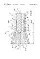
- FIG. 3is an enlarged, fragmentary side elevation view, in cross-section, of the horn antenna device of FIG. 2 .
- FIG. 4is a fragmentary side elevation view, in cross-section, of an alternative embodiment of the horn antenna device of FIG. 2 including an impedance matching device.
- FIG. 5is an enlarged, fragmentary, side elevation view, in cross-section, of an alternative embodiment of the horn antenna assembly of FIG. 2 having an interference device.
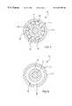
- FIG. 6is an enlarged front elevation view, in cross-section, of the interference device taken substantially along the plane of the line 6 — 6 in FIG. 5 .
- FIG. 7is an front elevation view, in cross-section, of an alternative embodiment of the interference device of FIG. 6 .
- a microwave ablation instrumentincluding a transmission line 11 having a first conductor 12 and a second conductor 13 (FIG. 3) suitable for the transmission of microwave energy, and having a proximal end connector 25 thereof coupled to a microwave energy source (not shown).
- the ablation instrument 10further includes a horn antenna device, generally designated 15 , having an antenna outer conductor 16 and an antenna inner conductor 17 .
- the outer conductor 16 of the horn antenna device 15is electrically coupled to the second conductor 13 of the transmission line 11 , and includes a peripherally extending interior wall 18 flaring outwardly to define a recess therein.
- the inner conductor of the horn antennais electrically coupled to the first conductor of the transmission line and terminates in the outer conductor recess.
- the inner conductor and the outer conductorcooperate to emit an electromagnetic field sufficiently strong to cause tissue ablation in a direction generally away from the flared interior wall of the outer conductor.
- a microwave ablation instrumentthat utilizes a horn antenna design to create an end-fire electromagnetic field for ablating biological tissue.
- this horn antenna arrangementreflects and focuses the microwave energy emitted radially from the antenna inner conductor generally in a direction away from the horn assembly (FIG. 3 ).
- a more concentrated electromagnetic energy fieldcan thus be directed toward a region distal to the horn antenna thereby allowing for deeper penetration of biological tissues.
- the effective ablation areais substantially increased over current end-firing ablation instruments which typically utilize transverse mounted helical coils as the antenna structure, while maintaining ablation accuracy of the targeted tissue.
- the targeted tissuesas a consequence, can be ablated without impacting the surrounding untargeted tissues.
- end-fireencompasses electromagnetic fields that have a significant component directed to a controlled region distal to the horn antenna assembly. Tissue ablation can thus be more strategically controlled, directed and performed without concern for undesirable ablation of other adjacent tissues which may otherwise be within the electromagnetic ablation range radially emanating from the antenna.
- This “end-fire” ablation instrumentis thus particularly suitable for ablation procedures requiring accurate tissue ablations or lesion formation such as those reserved for open-chest or minimally invasive MAZE III procedures to treat atrial arrhythmias, or for cardiac disrhythmias and tachycardia.
- the ablation instrument 10includes a handle 20 coupled to the horn antenna device 15 through an elongated tubular shaft 21 .
- the distal contact surface 22 of the horn antenna assemblymay be oriented and positioned against the targeted tissue to perform the desired ablation.
- the shaft 21is preferably provided by a metallic hypotube which the horn assembly may be supported through brazing paste, welding or the like. Moreover, the shaft 21 is preferably bendable and malleable in nature to enable shape reconfiguration to position the antenna and the cradle device at a desired orientation relative the handle. This enables the surgeon to appropriately angle the distal contact surface 22 toward the targeted region for tissue ablation. It will be appreciated, however, that the material of the shaft is further sufficiently rigid, although bendable, so that the shaft is not easily deformed upon the application of pressure during ablative use. Such materials, for example, includes stainless steel or aluminum having diameters ranging from about 0.090 inches to about 0.200 inches with wall thickness ranging from about 0.050 inches to about 0.025 inches. Most preferably, the shaft is 304 stainless steel having an outer diameter of about 0.120 inches and a wall thickness of about 0.013 inches.
- the transmission line 11extends through handle 20 and into a passage 23 of the tubular shaft 21 for electrical coupling to the distally mounted horn antenna assembly.
- an electrical connector 25which electrically couples the horn antenna device 15 to an external power supply (not shown).
- the transmission line 11may be provided by any type transmission line that is capable of transmitting microwave energy (e.g., coaxial cable, rectangular wave guides, stripline, slotline, microstripline).
- the transmission lineis provided by a semi-rigid coaxial transmission line having a line inner conductor 12 , a line outer conductor 13 and a line dielectric material 26 disposed between line inner conductor 12 and outer conductor 13 .
- the line inner and outer conductors in any of the above embodimentsmay be composed of any suitable conductive material that can transmit microwave energy such as copper, silver or gold wire, plated wires such as silver plated copper, aluminum, and the like.
- the transmission line 11may include a flexible outer tubing (not shown) to add rigidity and to provide protection to the outer conductor.
- the power supply(not shown) includes a microwave generator which may take any conventional form.
- the optimal frequenciesare generally in the neighborhood of the optimal frequency for heating water.
- frequencies in the range of approximately 800 MHz to 6 GHzwork well.
- the frequencies that are approved by the U.S. Food and Drug Administration for experimental clinical workare 915 MHz and 2.45 GHz. Therefore, a power supply having the capacity to emit microwave energy at frequencies in the neighborhood of 2.45 GHz may be chosen.
- solid state microwave generators in the 1-3 GHz rangeare expensive. Therefore, a conventional magnetron of the type commonly used in microwave ovens is utilized as the generator. It should be appreciated, however, that any other suitable microwave power source could be substituted in its place, and that the explained concepts may be applied at other frequencies like about 434 MHz, 915 MHz or 5.8 GHz (ISM band).
- a frequent concern in the management of microwave energyis impedance matching of the various transmission line components with that of the power source.
- An impedance mismatchwill reflect some portion of the incident power back to the power source resulting in reduced energy transmission and increased losses, typically manifested as heat generation due to line or wave guide attenuation. Reflected power can heat the transmission cable and generator causing substantial damage. More importantly, a heated transmission line may potentially burn a patient during the ablation process. Accordingly, it is desirable to match the impedance of the transmission line with the incident power of the power source, which is typically on the order of fifty (50) ohms. If the impedance is properly matched, substantially all the power may be transmitted through the line and reflections may be minimized.
- the transmission line 11is therefore preferably provided by a conventional fifty (50) ohm coaxial design suitable for the transmission of microwave energy at frequencies in the range of about 400 to about 6000 megahertz.
- the size and materials of the line inner conductor 12 , as well as the size, shape and material of the line dielectric material medium 26must be carefully selected.
- Each of these variables of the transmission line, together with other factors related to the antenna device,may be used to adjust the impedance and energy transmission characteristics of the antenna device.
- the horn antenna device 15is formed by flaring outwardly the distal portion of the line outer conductor 13 to form the antenna outer conductor 16 .
- the antenna outer conductor 16is therefore integrally formed with line outer conductor 13 .
- the inner peripheral wall 18 of the horn antennapreferably defines a conical shaped recess 27 upon which the antenna inner conductor terminates.
- the distal portion of line inner conductor 12terminates in the recess 27 of the horn antenna device 15 to form the antenna inner conductor 17 .
- the antenna inner conductor 17is also essentially integrally formed with the line inner conductor 12 .
- both the antenna outer and inner conductorsmay be provided by any conductive independent structure, such as spring steel, aluminum, beryllium copper, or silver-plated copper, which is conductively coupled to the respective line outer and inner conductor without departing from the true spirit and nature of the present invention.
- the conductive mounting of either antenna conductormay be performed through soldering, brazing, ultrasonic welding or adhesive bonding or the like.
- the distal section of the line inner conductor 12preferably extends past the proximal face 28 of the antenna dielectric material 30 to form a monopole antenna (i.e., the antenna inner conductor 17 ).
- the radiation pattern of the antenna inner conductortherefore, is radially emitted in a substantially cylindrical manner, and is consistent with the length thereof.
- the inner peripheral wall 18 of the antenna outer conductor 16is flared outwardly, the electromagnetic radiation emitted by the antenna inner conductor 17 will be reflected and redirected off the inner peripheral wall in directions distal to the horn antenna assembly (represented by arrows 31 in FIG. 3 ).
- This distally redirected and reflected microwave energyis distributed with greater accuracy, and with less dispersion than a conventional monopole antenna without a horn reflector.
- the microwave energy directed toward the targeted tissuecan therefore be intensified without having to increase the is antenna output.
- this more concentrated microwave energyenables deeper biological tissue penetration.
- the usable ablation areais substantially increased.
- FIG. 3illustrates a cross-sectional side elevation view of the horn antenna device 15 .
- the antenna outer conductor 16includes peripherally extending interior wall 18 flaring outwardly from the proximal face 28 of the dielectric material 30 to the distal face 32 thereof.
- This outward flare of the interior wall 18is generally linear in profile, and collectively forms a conical-shaped outer conductor.
- the outward flaremay be arcuate, convex, concave, etc.
- any conical shapede.g., oblique, frustum
- pyramidal shapede.g., oblique rectangular, tetrahedral recess which functions to reflect and redirect the electromagnetic energy distal to the horn antenna device 15 .
- the interior wall 18 of the antenna outer conductor 16is oriented at an acute angle relative the longitudinal axis to redirect the electromagnetic waves distal to the horn assembly.
- This acute angleis preferably in the range of about 15° to about 75°.
- the smaller the acute anglethe smaller the impact area.
- the reflected and redirected electromagnetic radiation for this smaller impact areais generally more intense.
- the greater the acute anglethe larger the impact area, but the less intense the emitted electromagnetic radiation.
- the diameter of the face 38must be equal to ⁇ /2 where ⁇ is the wavelength in the recess 27 (the wavelength depends on the dielectric constant of the material that filled 27 (dielectric material 30 )
- the antenna dielectric material 30is shown disposed in the recess 27 of the antenna outer conductor 16 .
- the electromagnetic waveencounters the antenna dielectric material 30 , via the proximal face, before entering the recess 27 of the horn antenna. Subsequently, the electromagnetic waves are emitted from the antenna inner conductor 17 and propagate through the antenna dielectric material 30 .
- the antenna dielectric material 30must therefore be suitable to facilitate transmission of the electromagnetic waves reflected off the antenna outer conductor, from the proximal face 28 to the distal face 32 thereof, while minimizing absorption of the microwaves. Accordingly, the dielectric material must exhibit the suitable microwave characteristics, for proper operation.
- the antenna dielectric material 30is composed of a silicon and TEFLON® composite, although other suitable materials may be used as well such as ceramic powder, polyethylene and polyolifin.
- the distal face 32 of the antenna dielectric material 30essentially forms a radiative window for the horn antenna device 15 upon which the electromagnetic radiation can be transmitted therefrom.
- this distal face 32which generally contacts the targeted biological tissue (i.e., a distal contact surface 22 ) during ablation, and is therefore preferably substantially smooth and substantially planar.
- the distal contact surface 22 of the horn antennamay be curvilinear or adapted to the shape of the tissue being ablated to assure conductive contact.
- the distal facewill be circular-shaped (i.e., circle, oval, etc.). However, a polygonal-shaped (i.e., square, rectangle, hexagon, etc.) or any other conceivable shape may also be used for the distal face.
- an impedance match between the dielectric components and that of the targeted tissueis an important consideration when selecting the antenna dielectric material composition.
- the dielectric properties of the line dielectric material 26 and that of the tissue being ablatedare already predetermined.
- the line dielectric materialis chosen to match the impedance with the power source (i.e., at fifty (50) ohms), while the dielectric properties of the targeted bio-tissues are substantially the same for all patients.
- a suitable antenna dielectric materialwould be chosen having a dielectric constant ( ⁇ a ) determined by the following equation:
- ⁇ a( ⁇ l ⁇ t ) 1 ⁇ 2
- ⁇ lis the dielectric constant of the line dielectric material 26
- ⁇ tis the dielectric constant of the tissue to be ablated.
- a quarter wave transformer devicemay be provided to further facilitate impedance matching, or the power transfer between the horn antenna device 15 and the targeted tissue.
- reflection of the electromagnetic waveis further minimized at the tissue surface by physically positioning this device 37 between the antenna dielectric material 30 and the targeted tissue (not shown).
- the quarter wave transformer 37includes a proximal face 38 which is placed in conductive contact with a distal face 32 of the antenna dielectric material 30 .
- This deviceforms a waveguide having and impedance Z md that may be calculated using the following equation:
- ⁇ tis the dielectric constant of the tissue to be ablated and Z a is the impedance of the horn antenna on the surface port defined by surface 32 .
- n1, 3, 5, 7, . . . and
- ⁇ mdis the wavelength in the impedance transformer ( 37 ). This wavelength is a function of the propagation mode as well as the geometry of the impedance transformer.
- L mdn ⁇ ⁇ md 2
- n1,2,3, . . .
- the dielectric material composition of the impedance matching device 37must also exhibit suitable microwave properties to facilitate transmission of the electromagnetic waves propagating therethrough, while minimizing absorption of the microwaves.
- the impedance matching device dielectric materialis preferably composed of a silicon and TEFLON® composite having the proper dielectric constant ⁇ md .
- Other proper materialsmay be employed such as ceramic powders.
- the distal contact surface 22corresponds to the distal face 41 of the matching device 37 , and functions as the radiative window of the horn antenna device 15 . As indicated, this contacting surface is employed to conductively contact the targeted biological tissue during ablation. It should be noted that this distal contact surface 22 may also be curvilinear or adapted to the shape of the tissue being ablated to assure conductive contact.
- FIG. 5another embodiment of the present invention is illustrated which includes an interference device 42 oriented along the path of the propagating incident wave and positioned proximal to the distal contact surface 22 of the horn antenna device 15 .
- the reflected electromagnetic waverepresented by arrow 43 in FIG. 5
- the interference device 42represented by arrow 45
- the reflection of the incident electromagnetic wave caused by the impedance mismatch at the contacting face/tissue interfacewill travel back toward the power supply until the reflected wave encounters a reflection face 46 of the interference device 42 . Consequently, this structural barrier causes a re-reflection (represented by arrow 45 ) of the reflected wave 43 back toward the distal contact surface 22 of the horn assembly.
- the interference device 42is composed of a metallic or dielectric material which creates an impedance mismatch with the dielectric material which the interference device is embedded in. Accordingly, when the reflected wave 43 encounters the sharp transition at the reflection face 46 , the reflected wave 43 is re-reflected back toward the distal contact surface of the horn antenna device 15 (represented by arrow 45 ).
- the interference device 42is in the shape of an annular ridge which is embedded in the line dielectric material 26 between line outer conductor 12 and line inner conductor 13 .
- FIG. 6best illustrates that the reflection face 46 of the interference device 42 is preferably ring-shaped, and is oriented substantially perpendicular to the longitudinal axis of the transmission line 11 and substantially parallel to the distal contact surface 22 .
- the radial height of the annular ringis preferably about one quarter (1 ⁇ 4) to about three-quarters (3 ⁇ 4) the radius of line dielectric material 26 , and extends substantially continuously from the line outer conductor 13 towards the line inner conductor 12 .
- the reflection face 46accordingly, forms a sharp transition barrier which functions to re-reflect (represented by arrow 45 ) a substantial part of the reflected incident wave 43 back toward the distal contact surface 22 of the horn antenna device 15 .
- the ridge of interference device 42increases the overall efficiency of the ablation instrument and the energy transfer at the tissue by substantially reducing the reflected power of the transmitted wave.
- the reflection face 46 of the interference device 42has been shown and described as a substantially continuous ring extending annularly about the line inner conductor 12 , it will be appreciated that the reflection face may be provided by a plurality of individual, radially spaced ridge members 47 (FIG. 7 ). Collectively, the individual reflection face portions 48 of the corresponding ridge members 47 form the reflection face 46 .
- this transition wall portion 50has a relatively gradual slope which enables a smooth transition in impedance as the transmitted wave propagates past interference device 42 and toward the distal contact surface 22 of horn antenna device 15 .
- the smooth transitioning wall portion 50substantially reduces reflection of the incident electromagnetic wave propagating past interference device 42 and toward the horn antenna device 15 .
- the smooth transition wall portion 50induces the electromagnetic wave to gradually ramps up past the interference device 42 so that only a small percentage of microwave energy is reflect back towards the generator.
- transition wall portion 50is shown as relatively linear, a plurality of other gradual slopes may apply which offer a smooth transition for the propagating electromagnetic wave.
- the reflection face 46 of the interference device 42is spaced-apart from the distal contact surface 22 of horn antenna device 15 by a predetermined distance which causes a constructive interference with the incident electromagnetic wave (represented by arrow 51 in FIG. 5) propagating past the interference device 42 and through the horn antenna assembly.
- a resonance in the hornis created where the phase difference between the incident electromagnetic wave 51 and the re-reflected incident wave (represented by arrow 45 ) is substantially 0°. Accordingly, the in-phase electromagnetic waves are converged to increase the amplitude and intensity of the electromagnetic field propagating from the interference device through the horn antenna device 15 .
Landscapes
- Health & Medical Sciences (AREA)
- Surgery (AREA)
- Life Sciences & Earth Sciences (AREA)
- Biomedical Technology (AREA)
- Medical Informatics (AREA)
- Nuclear Medicine, Radiotherapy & Molecular Imaging (AREA)
- Electromagnetism (AREA)
- Engineering & Computer Science (AREA)
- Physics & Mathematics (AREA)
- Heart & Thoracic Surgery (AREA)
- Otolaryngology (AREA)
- Molecular Biology (AREA)
- Animal Behavior & Ethology (AREA)
- General Health & Medical Sciences (AREA)
- Public Health (AREA)
- Veterinary Medicine (AREA)
- Surgical Instruments (AREA)
Abstract
Description


Claims (13)
Priority Applications (2)
| Application Number | Priority Date | Filing Date | Title |
|---|---|---|---|
| US09/333,747US6287302B1 (en) | 1999-06-14 | 1999-06-14 | End-firing microwave ablation instrument with horn reflection device |
| US09/861,027US6527768B2 (en) | 1999-06-14 | 2001-05-18 | End-firing microwave ablation instrument with horn reflection device |
Applications Claiming Priority (1)
| Application Number | Priority Date | Filing Date | Title |
|---|---|---|---|
| US09/333,747US6287302B1 (en) | 1999-06-14 | 1999-06-14 | End-firing microwave ablation instrument with horn reflection device |
Related Child Applications (1)
| Application Number | Title | Priority Date | Filing Date |
|---|---|---|---|
| US09/861,027DivisionUS6527768B2 (en) | 1999-06-14 | 2001-05-18 | End-firing microwave ablation instrument with horn reflection device |
Publications (1)
| Publication Number | Publication Date |
|---|---|
| US6287302B1true US6287302B1 (en) | 2001-09-11 |
Family
ID=23304092
Family Applications (2)
| Application Number | Title | Priority Date | Filing Date |
|---|---|---|---|
| US09/333,747Expired - Fee RelatedUS6287302B1 (en) | 1999-06-14 | 1999-06-14 | End-firing microwave ablation instrument with horn reflection device |
| US09/861,027Expired - Fee RelatedUS6527768B2 (en) | 1999-06-14 | 2001-05-18 | End-firing microwave ablation instrument with horn reflection device |
Family Applications After (1)
| Application Number | Title | Priority Date | Filing Date |
|---|---|---|---|
| US09/861,027Expired - Fee RelatedUS6527768B2 (en) | 1999-06-14 | 2001-05-18 | End-firing microwave ablation instrument with horn reflection device |
Country Status (1)
| Country | Link |
|---|---|
| US (2) | US6287302B1 (en) |
Cited By (100)
| Publication number | Priority date | Publication date | Assignee | Title |
|---|---|---|---|---|
| US6471696B1 (en)* | 2000-04-12 | 2002-10-29 | Afx, Inc. | Microwave ablation instrument with a directional radiation pattern |
| US6576000B2 (en)* | 2001-03-06 | 2003-06-10 | Scimed Life Systems, Inc. | Devices and methods for tissue repair |
| US20030187366A1 (en)* | 2002-01-04 | 2003-10-02 | Dune Medical Devices Ltd. | Method and system for examining tissue according to the dielectric properties thereof |
| US6673068B1 (en) | 2000-04-12 | 2004-01-06 | Afx, Inc. | Electrode arrangement for use in a medical instrument |
| US6802840B2 (en) | 2000-12-29 | 2004-10-12 | Afx, Inc. | Medical instrument positioning tool and method |
| WO2004112628A1 (en)* | 2003-06-23 | 2004-12-29 | Microsulis Limited | Radiation applicator for microwave medical treatment |
| US6955640B2 (en) | 2001-09-28 | 2005-10-18 | Cardiac Pacemakers, Inc. | Brachytherapy for arrhythmias |
| US7033352B1 (en) | 2000-01-18 | 2006-04-25 | Afx, Inc. | Flexible ablation instrument |
| US7052491B2 (en) | 1998-10-23 | 2006-05-30 | Afx, Inc. | Vacuum-assisted securing apparatus for a microwave ablation instrument |
| US20060155270A1 (en)* | 2002-11-27 | 2006-07-13 | Hancock Christopher P | Tissue ablation apparatus and method of ablating tissue |
| US7099717B2 (en) | 2002-01-03 | 2006-08-29 | Afx Inc. | Catheter having improved steering |
| US7118590B1 (en)* | 1999-02-25 | 2006-10-10 | Microsulis Limited | Radiation applicator |
| US20060253107A1 (en)* | 2004-03-23 | 2006-11-09 | Dune Medical Devices Ltd. | Clean margin assessment tool |
| US20060276781A1 (en)* | 2004-04-29 | 2006-12-07 | Van Der Weide Daniel W | Cannula cooling and positioning device |
| US20060289528A1 (en)* | 2003-03-26 | 2006-12-28 | Heng-Mao Chiu | Microwave antenna for medical ablation |
| US7192427B2 (en) | 2002-02-19 | 2007-03-20 | Afx, Inc. | Apparatus and method for assessing transmurality of a tissue ablation |
| US7226446B1 (en) | 1999-05-04 | 2007-06-05 | Dinesh Mody | Surgical microwave ablation assembly |
| US20070255169A1 (en)* | 2001-11-19 | 2007-11-01 | Dune Medical Devices Ltd. | Clean margin assessment tool |
| US20070288079A1 (en)* | 2006-03-24 | 2007-12-13 | Micrablate | Energy delivery system and uses thereof |
| US20080021343A1 (en)* | 2002-01-04 | 2008-01-24 | Dune Medical Devices Ltd. | Probes, systems, and methods for examining tissue according to the dielectric properties thereof |
| US7346399B2 (en) | 1999-05-28 | 2008-03-18 | Afx, Inc. | Monopole tip for ablation catheter |
| US20080214953A1 (en)* | 2007-03-01 | 2008-09-04 | Dune Medical Devices Ltd. | Tissue-characterization system and method |
| US20080234574A1 (en)* | 2004-05-26 | 2008-09-25 | Medical Device Innovations Limited | Tissue Detection and Ablation Apparatus and Apparatus and Method For Actuating a Tuner |
| US7467015B2 (en) | 2004-04-29 | 2008-12-16 | Neuwave Medical, Inc. | Segmented catheter for tissue ablation |
| US20090062637A1 (en)* | 2005-03-29 | 2009-03-05 | Dune Medical Devices Ltd. | Electromagnetic Sensors for Tissue Characterization |
| US7505811B2 (en) | 2001-11-19 | 2009-03-17 | Dune Medical Devices Ltd. | Method and apparatus for examining tissue for predefined target cells, particularly cancerous cells, and a probe useful in such method and apparatus |
| US20090082762A1 (en)* | 2007-09-20 | 2009-03-26 | Ormsby Theodore C | Radio frequency energy transmission device for the ablation of biological tissues |
| US20090131926A1 (en)* | 2007-11-16 | 2009-05-21 | Tyco Healthcare Group Lp | Dynamically Matched Microwave Antenna for Tissue Ablation |
| US20090183895A1 (en)* | 2008-01-23 | 2009-07-23 | Vivant Medical, Inc. | Thermally Tuned Coaxial Cable for Microwave Antennas |
| US20090198226A1 (en)* | 2008-01-31 | 2009-08-06 | Vivant Medical, Inc. | Medical Device Including Member that Deploys in a Spiral-Like Configuration and Method |
| US20090295674A1 (en)* | 2008-05-29 | 2009-12-03 | Kenlyn Bonn | Slidable Choke Microwave Antenna |
| US20100121319A1 (en)* | 2008-11-10 | 2010-05-13 | Microcube, Llc | Methods and devices for applying energy to bodily tissues |
| US20100125269A1 (en)* | 2008-10-21 | 2010-05-20 | Microcube, Limited Liability Corporation | Microwave treatment devices and methods |
| US7809425B2 (en) | 2003-07-24 | 2010-10-05 | Dune Medical Devices Ltd. | Method and apparatus for examining a substance, particularly tissue, to characterize its type |
| US20110004205A1 (en)* | 2008-10-21 | 2011-01-06 | Chu Chun Yiu | Methods and devices for delivering microwave energy |
| GB2472012A (en)* | 2009-07-20 | 2011-01-26 | Microoncology Ltd | Microwave antenna with flat paddle shape |
| WO2011017168A2 (en) | 2009-07-28 | 2011-02-10 | Neuwave Medical, Inc. | Energy delivery systems and uses thereof |
| GB2472972A (en)* | 2009-07-20 | 2011-03-02 | Microoncology Ltd | A microwave antenna |
| US7904145B2 (en) | 2004-03-23 | 2011-03-08 | Dune Medical Devices Ltd. | Clean margin assessment tool |
| US20110077634A1 (en)* | 2009-09-28 | 2011-03-31 | Vivant Medical, Inc. | Microwave Surface Ablation Using Conical Probe |
| US20110077636A1 (en)* | 2009-09-29 | 2011-03-31 | Vivant Medical, Inc. | Management of Voltage Standing Wave Ratio at Skin Surface During Microwave Ablation |
| US20110077633A1 (en)* | 2009-09-28 | 2011-03-31 | Vivant Medical, Inc. | Electrosurgical Devices, Directional Reflector Assemblies Coupleable Thereto, and Electrosurgical Systems Including Same |
| US20110098697A1 (en)* | 2009-10-28 | 2011-04-28 | Vivant Medical, Inc. | System and Method for Monitoring Ablation Size |
| US20110213353A1 (en)* | 2010-02-26 | 2011-09-01 | Lee Anthony C | Tissue Ablation System With Internal And External Radiation Sources |
| US8019411B2 (en) | 2002-01-04 | 2011-09-13 | Dune Medical Devices Ltd. | Probes, systems, and methods for examining tissue according to the dielectric properties thereof |
| US8116845B2 (en) | 2005-08-04 | 2012-02-14 | Dune Medical Devices Ltd. | Tissue-characterization probe with effective sensor-to-tissue contact |
| US20130041362A1 (en)* | 2011-08-09 | 2013-02-14 | Vivant Medical, Inc. | Microwave Antenna Having a Coaxial Cable with an Adjustable Outer Conductor Configuration |
| US8401668B2 (en) | 2007-04-19 | 2013-03-19 | Miramar Labs, Inc. | Systems and methods for creating an effect using microwave energy to specified tissue |
| US8406894B2 (en) | 2007-12-12 | 2013-03-26 | Miramar Labs, Inc. | Systems, apparatus, methods and procedures for the noninvasive treatment of tissue using microwave energy |
| US8469951B2 (en) | 2011-08-01 | 2013-06-25 | Miramar Labs, Inc. | Applicator and tissue interface module for dermatological device |
| US8672932B2 (en) | 2006-03-24 | 2014-03-18 | Neuwave Medical, Inc. | Center fed dipole for use with tissue ablation systems, devices and methods |
| US8688228B2 (en) | 2007-04-19 | 2014-04-01 | Miramar Labs, Inc. | Systems, apparatus, methods and procedures for the noninvasive treatment of tissue using microwave energy |
| US8721565B2 (en) | 2005-08-04 | 2014-05-13 | Dune Medical Devices Ltd. | Device for forming an effective sensor-to-tissue contact |
| US20140180269A1 (en)* | 2010-06-30 | 2014-06-26 | Covidien Lp | Microwave antenna having a reactively-loaded loop configuration |
| US8853600B2 (en) | 1997-07-31 | 2014-10-07 | Miramar Labs, Inc. | Method and apparatus for treating subcutaneous histological features |
| US20150045785A1 (en)* | 2011-12-14 | 2015-02-12 | Emblation Limited | Microwave applicator and method of forming a microwave applicator |
| US8968300B2 (en) | 2009-08-05 | 2015-03-03 | Covidien Lp | Electrosurgical devices having dielectric loaded coaxial aperture with distally positioned resonant structure |
| US20150164588A1 (en)* | 2009-02-20 | 2015-06-18 | Covidien Lp | Leaky-wave antennas for medical applications |
| US9149331B2 (en) | 2007-04-19 | 2015-10-06 | Miramar Labs, Inc. | Methods and apparatus for reducing sweat production |
| WO2015171033A1 (en)* | 2014-05-05 | 2015-11-12 | Per Olov Risman | Microwave antenna applicator |
| US9192438B2 (en) | 2011-12-21 | 2015-11-24 | Neuwave Medical, Inc. | Energy delivery systems and uses thereof |
| US9241763B2 (en) | 2007-04-19 | 2016-01-26 | Miramar Labs, Inc. | Systems, apparatus, methods and procedures for the noninvasive treatment of tissue using microwave energy |
| WO2017080775A2 (en) | 2015-11-09 | 2017-05-18 | Opr Mikrovågsteknik Ekonomisk Förening | Quantification of inhomogeneities in objects by electromagnetic fields |
| WO2017103209A1 (en)* | 2015-12-17 | 2017-06-22 | Creo Medical Limited | Electrosurgical probe for delivering microwave energy |
| US20170181420A1 (en)* | 2012-02-17 | 2017-06-29 | Nathaniel L. Cohen | Apparatus for using microwave energy for insect and pest control and methods thereof |
| US9750425B2 (en) | 2004-03-23 | 2017-09-05 | Dune Medical Devices Ltd. | Graphical user interfaces (GUI), methods and apparatus for data presentation |
| US9757197B2 (en) | 2009-10-06 | 2017-09-12 | Angiodynamics, Inc. | Medical devices and pumps therefor |
| US20170265940A1 (en)* | 2014-12-02 | 2017-09-21 | Kansas State University Research Foundation | High-efficiency, directional microwave ablation antenna |
| US9788896B2 (en) | 2004-07-02 | 2017-10-17 | Angiodynamics, Inc. | Radiation applicator and method of radiating tissue |
| WO2017180877A2 (en) | 2016-04-15 | 2017-10-19 | Neuwave Medical, Inc. | Systems and methods for energy delivery |
| US9861440B2 (en) | 2010-05-03 | 2018-01-09 | Neuwave Medical, Inc. | Energy delivery systems and uses thereof |
| US9907613B2 (en) | 2005-07-01 | 2018-03-06 | Angiodynamics, Inc. | Radiation applicator and method of radiating tissue |
| WO2018146159A1 (en)* | 2017-02-10 | 2018-08-16 | Creo Medical Limited | Electrosurgical apparatus and electrosurgical instrument |
| US10342614B2 (en) | 2004-04-29 | 2019-07-09 | Wisconsin Alumni Research Foundation | Triaxial antenna for microwave tissue ablation |
| WO2019135135A1 (en) | 2018-01-03 | 2019-07-11 | Neuwave Medical, Inc. | Systems and methods for energy delivery |
| US10363092B2 (en) | 2006-03-24 | 2019-07-30 | Neuwave Medical, Inc. | Transmission line with heat transfer ability |
| US10376314B2 (en) | 2006-07-14 | 2019-08-13 | Neuwave Medical, Inc. | Energy delivery systems and uses thereof |
| WO2019159041A1 (en) | 2018-02-15 | 2019-08-22 | Neuwave Medical, Inc. | Compositions and methods for directing endoscopic devices |
| WO2019159040A1 (en) | 2018-02-15 | 2019-08-22 | Neuwave Medical, Inc. | Energy delivery device |
| WO2019162786A1 (en) | 2018-02-26 | 2019-08-29 | Neuwave Medical, Inc. | Energy delivery devices with flexible and adjustable tips |
| CN110381623A (en)* | 2019-08-07 | 2019-10-25 | 昆山九华电子设备厂 | A kind of microwave heating antenna |
| US10463429B2 (en) | 2007-04-19 | 2019-11-05 | Miradry, Inc. | Methods, devices, and systems for non-invasive delivery of microwave therapy |
| EP3626194A1 (en) | 2006-07-14 | 2020-03-25 | Neuwave Medical, Inc. | Energy delivery system |
| US10624696B2 (en) | 2007-04-19 | 2020-04-21 | Miradry, Inc. | Systems and methods for creating an effect using microwave energy to specified tissue |
| WO2020109999A1 (en) | 2018-11-27 | 2020-06-04 | Neuwave Medical, Inc. | Endoscopic system for energy delivery |
| WO2020121279A1 (en) | 2018-12-13 | 2020-06-18 | Neuwave Medical, Inc. | Energy delivery devices and related systems |
| WO2020183262A1 (en) | 2019-03-08 | 2020-09-17 | Neuwave Medical, Inc. | Systems and methods for energy delivery |
| US10779885B2 (en) | 2013-07-24 | 2020-09-22 | Miradry. Inc. | Apparatus and methods for the treatment of tissue using microwave energy |
| EP3747391A1 (en) | 2015-10-26 | 2020-12-09 | Neuwave Medical, Inc. | Apparatuses for securing a medical device and related methods thereof |
| US10952792B2 (en) | 2015-10-26 | 2021-03-23 | Neuwave Medical, Inc. | Energy delivery systems and uses thereof |
| CN113796954A (en)* | 2021-10-11 | 2021-12-17 | 杭州市第一人民医院 | An ablation needle that can change the heating angle |
| US11219484B2 (en) | 2008-10-21 | 2022-01-11 | Microcube, Llc | Methods and devices for delivering microwave energy |
| US11291503B2 (en) | 2008-10-21 | 2022-04-05 | Microcube, Llc | Microwave treatment devices and methods |
| US11389235B2 (en) | 2006-07-14 | 2022-07-19 | Neuwave Medical, Inc. | Energy delivery systems and uses thereof |
| WO2023047218A1 (en) | 2021-09-22 | 2023-03-30 | Neuwave Medical, Inc. | Systems and methods for real-time image-based device localization |
| WO2023156965A1 (en) | 2022-02-18 | 2023-08-24 | Neuwave Medical, Inc. | Coupling devices and related systems |
| RU2806708C1 (en)* | 2023-03-22 | 2023-11-03 | Федеральное казенное предприятие "Научно-производственный центр "Дельта", ФКП "НПЦ "Дельта" | Antenna |
| WO2024176173A1 (en) | 2023-02-24 | 2024-08-29 | Neuwave Medical, Inc. | Temperature regulating devices and related systems and methods |
| US12239367B2 (en) | 2019-06-25 | 2025-03-04 | Microcube, Llc | Methods and devices for generating and delivering shaped microwave fields |
| USD1084316S1 (en) | 2023-11-20 | 2025-07-15 | Angiodynamics, Inc. | Ferrule |
Families Citing this family (45)
| Publication number | Priority date | Publication date | Assignee | Title |
|---|---|---|---|---|
| US20030163128A1 (en)* | 2000-12-29 | 2003-08-28 | Afx, Inc. | Tissue ablation system with a sliding ablating device and method |
| US20040106937A1 (en)* | 2002-06-21 | 2004-06-03 | Afx, Inc. | Clamp accessory and method for an ablation instrument |
| US7794454B2 (en)* | 2003-07-11 | 2010-09-14 | Medtronic Cryocath Lp | Method and device for epicardial ablation |
| US8491636B2 (en)* | 2004-03-23 | 2013-07-23 | Medtronic Cryopath LP | Method and apparatus for inflating and deflating balloon catheters |
| US7727228B2 (en) | 2004-03-23 | 2010-06-01 | Medtronic Cryocath Lp | Method and apparatus for inflating and deflating balloon catheters |
| US9555223B2 (en) | 2004-03-23 | 2017-01-31 | Medtronic Cryocath Lp | Method and apparatus for inflating and deflating balloon catheters |
| US20070016180A1 (en)* | 2004-04-29 | 2007-01-18 | Lee Fred T Jr | Microwave surgical device |
| US7244254B2 (en)* | 2004-04-29 | 2007-07-17 | Micrablate | Air-core microwave ablation antennas |
| US7186927B2 (en) | 2004-07-30 | 2007-03-06 | Bae Systems Information And Electronic Systems Integration Inc. | High frequency via with stripped semi-rigid cable |
| US7180009B2 (en)* | 2004-07-30 | 2007-02-20 | Bae Systems Information And Electronic Systems Inteegration Inc. | Transmission line with stripped semi-rigid cable |
| US7410485B1 (en) | 2005-01-14 | 2008-08-12 | The United States Of America As Represented By The Administrator Of The National Aeronautics And Space Administration | Directional microwave applicator and methods |
| US8932208B2 (en) | 2005-05-26 | 2015-01-13 | Maquet Cardiovascular Llc | Apparatus and methods for performing minimally-invasive surgical procedures |
| US20070185479A1 (en)* | 2006-02-06 | 2007-08-09 | Liming Lau | Methods and devices for performing ablation and assessing efficacy thereof |
| US7826904B2 (en)* | 2006-02-07 | 2010-11-02 | Angiodynamics, Inc. | Interstitial microwave system and method for thermal treatment of diseases |
| US20070225697A1 (en)* | 2006-03-23 | 2007-09-27 | Ketan Shroff | Apparatus and methods for cardiac ablation |
| US20080097251A1 (en)* | 2006-06-15 | 2008-04-24 | Eilaz Babaev | Method and apparatus for treating vascular obstructions |
| US20080039879A1 (en)* | 2006-08-09 | 2008-02-14 | Chin Albert K | Devices and methods for atrial appendage exclusion |
| US9232997B2 (en) | 2006-11-07 | 2016-01-12 | Corvia Medical, Inc. | Devices and methods for retrievable intra-atrial implants |
| US20110257723A1 (en) | 2006-11-07 | 2011-10-20 | Dc Devices, Inc. | Devices and methods for coronary sinus pressure relief |
| EP2097012A4 (en) | 2006-11-07 | 2012-08-15 | David Stephen Celermajer | Devices and methods for the treatment of heart failure |
| US10413284B2 (en) | 2006-11-07 | 2019-09-17 | Corvia Medical, Inc. | Atrial pressure regulation with control, sensing, monitoring and therapy delivery |
| WO2009045265A1 (en) | 2007-10-05 | 2009-04-09 | Maquet Cardiovascular, Llc | Devices and methods for minimally-invasive surgical procedures |
| US20090209986A1 (en)* | 2008-02-15 | 2009-08-20 | Stewart Michael C | Devices, Tools and Methods for Atrial Appendage Exclusion |
| US8777938B2 (en)* | 2009-06-04 | 2014-07-15 | Wisconsin Alumni Research Foundation | Fan-beam microwave horn for bloodless resection |
| US9757107B2 (en) | 2009-09-04 | 2017-09-12 | Corvia Medical, Inc. | Methods and devices for intra-atrial shunts having adjustable sizes |
| WO2011094521A2 (en) | 2010-01-29 | 2011-08-04 | Dc Devices, Inc. | Devices and methods for reducing venous pressure |
| EP2528646A4 (en) | 2010-01-29 | 2017-06-28 | DC Devices, Inc. | Devices and systems for treating heart failure |
| JP5786869B2 (en)* | 2011-01-24 | 2015-09-30 | 株式会社村田製作所 | Electric field probe |
| US12303119B2 (en) | 2011-02-10 | 2025-05-20 | Corvia Medical, Inc. | Apparatus and methods to create and maintain an intra-atrial pressure relief opening |
| WO2012109557A2 (en)* | 2011-02-10 | 2012-08-16 | Dc Devices, Inc. | Apparatus and methods to create and maintain an intra-atrial pressure relief opening |
| US8951223B2 (en) | 2011-12-22 | 2015-02-10 | Dc Devices, Inc. | Methods and devices for intra-atrial shunts having adjustable sizes |
| US9005155B2 (en) | 2012-02-03 | 2015-04-14 | Dc Devices, Inc. | Devices and methods for treating heart failure |
| US10588611B2 (en) | 2012-04-19 | 2020-03-17 | Corvia Medical Inc. | Implant retention attachment and method of use |
| US8906008B2 (en) | 2012-05-22 | 2014-12-09 | Covidien Lp | Electrosurgical instrument |
| US9649480B2 (en) | 2012-07-06 | 2017-05-16 | Corvia Medical, Inc. | Devices and methods of treating or ameliorating diastolic heart failure through pulmonary valve intervention |
| US9775636B2 (en) | 2013-03-12 | 2017-10-03 | Corvia Medical, Inc. | Devices, systems, and methods for treating heart failure |
| US10675450B2 (en) | 2014-03-12 | 2020-06-09 | Corvia Medical, Inc. | Devices and methods for treating heart failure |
| JP6799526B2 (en) | 2014-07-23 | 2020-12-16 | コルヴィア メディカル インコーポレイテッド | Equipment and methods for the treatment of heart failure |
| WO2016168435A1 (en) | 2015-04-14 | 2016-10-20 | Crysanthe, Inc. | System and method for selective treatment of skin and subcutaneous fat using a single frequency dual mode radio frequency antenna device |
| US10382976B2 (en)* | 2016-12-06 | 2019-08-13 | At&T Intellectual Property I, L.P. | Method and apparatus for managing wireless communications based on communication paths and network device positions |
| US10484120B2 (en)* | 2017-09-30 | 2019-11-19 | Intel Corporation | Waveguide couplers and junctions to enable frequency division multiplexed sensor systems in autonomous vehicle |
| GB201806193D0 (en)* | 2018-04-16 | 2018-05-30 | Emblation Ltd | Microwave application for the uterine cervix |
| CN110710963A (en)* | 2019-11-19 | 2020-01-21 | 山东一脉物联网科技有限公司 | Narrow-face type radar intelligent monitoring respiratory system |
| CN112691297B (en)* | 2020-11-19 | 2022-03-04 | 成都恒波医疗器械有限公司 | Saddle-shaped microwave irradiator |
| US20230014522A1 (en)* | 2021-07-16 | 2023-01-19 | Arthrex, Inc | Surgical electrode assembly with focal point projection |
Citations (1)
| Publication number | Priority date | Publication date | Assignee | Title |
|---|---|---|---|---|
| US4462412A (en)* | 1980-04-02 | 1984-07-31 | Bsd Medical Corporation | Annular electromagnetic radiation applicator for biological tissue, and method |
Family Cites Families (5)
| Publication number | Priority date | Publication date | Assignee | Title |
|---|---|---|---|---|
| US4641649A (en) | 1985-10-30 | 1987-02-10 | Rca Corporation | Method and apparatus for high frequency catheter ablation |
| US4945912A (en) | 1988-11-25 | 1990-08-07 | Sensor Electronics, Inc. | Catheter with radiofrequency heating applicator |
| US5314466A (en) | 1992-04-13 | 1994-05-24 | Ep Technologies, Inc. | Articulated unidirectional microwave antenna systems for cardiac ablation |
| US5405346A (en) | 1993-05-14 | 1995-04-11 | Fidus Medical Technology Corporation | Tunable microwave ablation catheter |
| US5800494A (en) | 1996-08-20 | 1998-09-01 | Fidus Medical Technology Corporation | Microwave ablation catheters having antennas with distal fire capabilities |
- 1999
- 1999-06-14USUS09/333,747patent/US6287302B1/ennot_activeExpired - Fee Related
- 2001
- 2001-05-18USUS09/861,027patent/US6527768B2/ennot_activeExpired - Fee Related
Patent Citations (1)
| Publication number | Priority date | Publication date | Assignee | Title |
|---|---|---|---|---|
| US4462412A (en)* | 1980-04-02 | 1984-07-31 | Bsd Medical Corporation | Annular electromagnetic radiation applicator for biological tissue, and method |
Cited By (232)
| Publication number | Priority date | Publication date | Assignee | Title |
|---|---|---|---|---|
| US8853600B2 (en) | 1997-07-31 | 2014-10-07 | Miramar Labs, Inc. | Method and apparatus for treating subcutaneous histological features |
| US7052491B2 (en) | 1998-10-23 | 2006-05-30 | Afx, Inc. | Vacuum-assisted securing apparatus for a microwave ablation instrument |
| US7387627B2 (en) | 1998-10-23 | 2008-06-17 | Maquet Cardiovascular Llc | Vacuum-assisted securing apparatus for a microwave ablation instrument |
| US7115126B2 (en) | 1998-10-23 | 2006-10-03 | Afx Inc. | Directional microwave ablation instrument with off-set energy delivery portion |
| US7118590B1 (en)* | 1999-02-25 | 2006-10-10 | Microsulis Limited | Radiation applicator |
| US7226446B1 (en) | 1999-05-04 | 2007-06-05 | Dinesh Mody | Surgical microwave ablation assembly |
| US7346399B2 (en) | 1999-05-28 | 2008-03-18 | Afx, Inc. | Monopole tip for ablation catheter |
| US20080071259A1 (en)* | 2000-01-18 | 2008-03-20 | Jules Gauthier | Microwave ablation instrument with flexible antenna assembly |
| US7033352B1 (en) | 2000-01-18 | 2006-04-25 | Afx, Inc. | Flexible ablation instrument |
| US7301131B2 (en) | 2000-01-18 | 2007-11-27 | Afx, Inc. | Microwave ablation instrument with flexible antenna assembly and method |
| US7156841B2 (en) | 2000-04-12 | 2007-01-02 | Afx, Inc. | Electrode arrangement for use in a medical instrument |
| US6976986B2 (en) | 2000-04-12 | 2005-12-20 | Afx, Inc. | Electrode arrangement for use in a medical instrument |
| US6471696B1 (en)* | 2000-04-12 | 2002-10-29 | Afx, Inc. | Microwave ablation instrument with a directional radiation pattern |
| US6673068B1 (en) | 2000-04-12 | 2004-01-06 | Afx, Inc. | Electrode arrangement for use in a medical instrument |
| US7303560B2 (en) | 2000-12-29 | 2007-12-04 | Afx, Inc. | Method of positioning a medical instrument |
| US6802840B2 (en) | 2000-12-29 | 2004-10-12 | Afx, Inc. | Medical instrument positioning tool and method |
| US6576000B2 (en)* | 2001-03-06 | 2003-06-10 | Scimed Life Systems, Inc. | Devices and methods for tissue repair |
| US6955640B2 (en) | 2001-09-28 | 2005-10-18 | Cardiac Pacemakers, Inc. | Brachytherapy for arrhythmias |
| US8195282B2 (en) | 2001-11-19 | 2012-06-05 | Dune Medical Devices Ltd | Method and apparatus for examining tissue for predefined target cells, particularly cancerous cells, and a probe useful in such method and apparatus |
| US20070255169A1 (en)* | 2001-11-19 | 2007-11-01 | Dune Medical Devices Ltd. | Clean margin assessment tool |
| US7505811B2 (en) | 2001-11-19 | 2009-03-17 | Dune Medical Devices Ltd. | Method and apparatus for examining tissue for predefined target cells, particularly cancerous cells, and a probe useful in such method and apparatus |
| US9226979B2 (en) | 2001-11-19 | 2016-01-05 | Dune Medical Devices Ltd. | Method and apparatus for examining tissue for predefined target cells, particularly cancerous cells, and a probe useful in such method and apparatus |
| US7099717B2 (en) | 2002-01-03 | 2006-08-29 | Afx Inc. | Catheter having improved steering |
| US8032211B2 (en) | 2002-01-04 | 2011-10-04 | Dune Medical Devices Ltd. | Probes, systems, and methods for examining tissue according to the dielectric properties thereof |
| US20050107718A1 (en)* | 2002-01-04 | 2005-05-19 | Dan Hashimshony | Method and system for examining tissue according to the dielectric properties thereof |
| US20080021343A1 (en)* | 2002-01-04 | 2008-01-24 | Dune Medical Devices Ltd. | Probes, systems, and methods for examining tissue according to the dielectric properties thereof |
| US20030187366A1 (en)* | 2002-01-04 | 2003-10-02 | Dune Medical Devices Ltd. | Method and system for examining tissue according to the dielectric properties thereof |
| US7184824B2 (en)* | 2002-01-04 | 2007-02-27 | Dune Medical Devices Ltd. | Method and system for examining tissue according to the dielectric properties thereof |
| WO2003060462A3 (en)* | 2002-01-04 | 2003-12-31 | Dune Medical Devices Ltd | Examining tissue according to dielectric properties thereof |
| US6813515B2 (en)* | 2002-01-04 | 2004-11-02 | Dune Medical Devices Ltd. | Method and system for examining tissue according to the dielectric properties thereof |
| US8019411B2 (en) | 2002-01-04 | 2011-09-13 | Dune Medical Devices Ltd. | Probes, systems, and methods for examining tissue according to the dielectric properties thereof |
| US20070149967A1 (en)* | 2002-02-19 | 2007-06-28 | Pierre-Antoine Chapelon | Apparatus and Method For Assessing Transmurality of a Tissue Ablation |
| US7192427B2 (en) | 2002-02-19 | 2007-03-20 | Afx, Inc. | Apparatus and method for assessing transmurality of a tissue ablation |
| US7497858B2 (en) | 2002-02-19 | 2009-03-03 | Maquet Cardiovascular Llc | Apparatus and method for assessing transmurality of a tissue ablation |
| US8768485B2 (en) | 2002-11-27 | 2014-07-01 | Medical Device Innovations Limited | Tissue ablation apparatus and method of ablating tissue |
| US20060155270A1 (en)* | 2002-11-27 | 2006-07-13 | Hancock Christopher P | Tissue ablation apparatus and method of ablating tissue |
| EP1613230A4 (en)* | 2003-03-26 | 2008-05-14 | Univ Sydney Tech | HYPERFREQUENCY ANTENNA FOR SURGICAL ABLATION |
| US20060289528A1 (en)* | 2003-03-26 | 2006-12-28 | Heng-Mao Chiu | Microwave antenna for medical ablation |
| US20070043346A1 (en)* | 2003-06-23 | 2007-02-22 | Nigel Cronin | Radiation applicator for microwave medical treatment |
| GB2418619B (en)* | 2003-06-23 | 2008-01-16 | Microsulis Ltd | Radiation applicator for microwave medical treatment |
| US20130267941A1 (en)* | 2003-06-23 | 2013-10-10 | Angiodynamics, Inc. | Radiation Applicator for Microwave Medical Treatment |
| US10772682B2 (en) | 2003-06-23 | 2020-09-15 | Angiodynamics, Inc. | Radiation applicator for microwave medical treatment |
| WO2004112628A1 (en)* | 2003-06-23 | 2004-12-29 | Microsulis Limited | Radiation applicator for microwave medical treatment |
| US9161811B2 (en)* | 2003-06-23 | 2015-10-20 | Angiodynamics, Inc. | Radiation applicator for microwave medical treatment |
| US9770295B2 (en) | 2003-06-23 | 2017-09-26 | Angiodynamics, Inc. | Radiation applicator for microwave medical treatment |
| GB2418619A (en)* | 2003-06-23 | 2006-04-05 | Microsulis Ltd | Radiation applicator for microwave medical treatment |
| US7809425B2 (en) | 2003-07-24 | 2010-10-05 | Dune Medical Devices Ltd. | Method and apparatus for examining a substance, particularly tissue, to characterize its type |
| US20060253107A1 (en)* | 2004-03-23 | 2006-11-09 | Dune Medical Devices Ltd. | Clean margin assessment tool |
| US11179053B2 (en) | 2004-03-23 | 2021-11-23 | Dilon Medical Technologies Ltd. | Graphical user interfaces (GUI), methods and apparatus for data presentation |
| US7720532B2 (en) | 2004-03-23 | 2010-05-18 | Dune Medical Ltd. | Clean margin assessment tool |
| US7904145B2 (en) | 2004-03-23 | 2011-03-08 | Dune Medical Devices Ltd. | Clean margin assessment tool |
| US9750425B2 (en) | 2004-03-23 | 2017-09-05 | Dune Medical Devices Ltd. | Graphical user interfaces (GUI), methods and apparatus for data presentation |
| US20060276781A1 (en)* | 2004-04-29 | 2006-12-07 | Van Der Weide Daniel W | Cannula cooling and positioning device |
| US10342614B2 (en) | 2004-04-29 | 2019-07-09 | Wisconsin Alumni Research Foundation | Triaxial antenna for microwave tissue ablation |
| US7467015B2 (en) | 2004-04-29 | 2008-12-16 | Neuwave Medical, Inc. | Segmented catheter for tissue ablation |
| US8805480B2 (en) | 2004-05-26 | 2014-08-12 | Medical Device Innovations Limited | Tissue detection and ablation apparatus and apparatus and method for actuating a tuner |
| US20080234574A1 (en)* | 2004-05-26 | 2008-09-25 | Medical Device Innovations Limited | Tissue Detection and Ablation Apparatus and Apparatus and Method For Actuating a Tuner |
| US9788896B2 (en) | 2004-07-02 | 2017-10-17 | Angiodynamics, Inc. | Radiation applicator and method of radiating tissue |
| US7899515B2 (en) | 2005-03-29 | 2011-03-01 | Dune Medical Devices Ltd. | Electromagnetic sensors for tissue characterization |
| US20090062637A1 (en)* | 2005-03-29 | 2009-03-05 | Dune Medical Devices Ltd. | Electromagnetic Sensors for Tissue Characterization |
| US9907613B2 (en) | 2005-07-01 | 2018-03-06 | Angiodynamics, Inc. | Radiation applicator and method of radiating tissue |
| US9526460B2 (en) | 2005-08-04 | 2016-12-27 | Dune Medical Devices Ltd. | Tissue-characterization probe with effective sensor-to-tissue contact |
| US8721565B2 (en) | 2005-08-04 | 2014-05-13 | Dune Medical Devices Ltd. | Device for forming an effective sensor-to-tissue contact |
| US8116845B2 (en) | 2005-08-04 | 2012-02-14 | Dune Medical Devices Ltd. | Tissue-characterization probe with effective sensor-to-tissue contact |
| US10363092B2 (en) | 2006-03-24 | 2019-07-30 | Neuwave Medical, Inc. | Transmission line with heat transfer ability |
| EP3797721A1 (en) | 2006-03-24 | 2021-03-31 | Neuwave Medical, Inc. | Transmission line with heat transfer ability |
| US20070288079A1 (en)* | 2006-03-24 | 2007-12-13 | Micrablate | Energy delivery system and uses thereof |
| US8672932B2 (en) | 2006-03-24 | 2014-03-18 | Neuwave Medical, Inc. | Center fed dipole for use with tissue ablation systems, devices and methods |
| US11944376B2 (en) | 2006-03-24 | 2024-04-02 | Neuwave Medical, Inc. | Transmission line with heat transfer ability |
| US11596474B2 (en) | 2006-07-14 | 2023-03-07 | Neuwave Medical, Inc. | Energy delivery systems and uses thereof |
| US10376314B2 (en) | 2006-07-14 | 2019-08-13 | Neuwave Medical, Inc. | Energy delivery systems and uses thereof |
| US11576722B2 (en) | 2006-07-14 | 2023-02-14 | Neuwave Medical, Inc. | Energy delivery systems and uses thereof |
| US11576723B2 (en) | 2006-07-14 | 2023-02-14 | Neuwave Medical, Inc. | Energy delivery systems and uses thereof |
| EP3626194A1 (en) | 2006-07-14 | 2020-03-25 | Neuwave Medical, Inc. | Energy delivery system |
| US11389235B2 (en) | 2006-07-14 | 2022-07-19 | Neuwave Medical, Inc. | Energy delivery systems and uses thereof |
| US8147423B2 (en) | 2007-03-01 | 2012-04-03 | Dune Medical Devices, Ltd. | Tissue-characterization system and method |
| US20080214953A1 (en)* | 2007-03-01 | 2008-09-04 | Dune Medical Devices Ltd. | Tissue-characterization system and method |
| US9427285B2 (en) | 2007-04-19 | 2016-08-30 | Miramar Labs, Inc. | Systems and methods for creating an effect using microwave energy to specified tissue |
| US9149331B2 (en) | 2007-04-19 | 2015-10-06 | Miramar Labs, Inc. | Methods and apparatus for reducing sweat production |
| US10166072B2 (en) | 2007-04-19 | 2019-01-01 | Miradry, Inc. | Systems and methods for creating an effect using microwave energy to specified tissue |
| US10463429B2 (en) | 2007-04-19 | 2019-11-05 | Miradry, Inc. | Methods, devices, and systems for non-invasive delivery of microwave therapy |
| US8401668B2 (en) | 2007-04-19 | 2013-03-19 | Miramar Labs, Inc. | Systems and methods for creating an effect using microwave energy to specified tissue |
| US9241763B2 (en) | 2007-04-19 | 2016-01-26 | Miramar Labs, Inc. | Systems, apparatus, methods and procedures for the noninvasive treatment of tissue using microwave energy |
| US8688228B2 (en) | 2007-04-19 | 2014-04-01 | Miramar Labs, Inc. | Systems, apparatus, methods and procedures for the noninvasive treatment of tissue using microwave energy |
| US10624696B2 (en) | 2007-04-19 | 2020-04-21 | Miradry, Inc. | Systems and methods for creating an effect using microwave energy to specified tissue |
| US11419678B2 (en) | 2007-04-19 | 2022-08-23 | Miradry, Inc. | Methods, devices, and systems for non-invasive delivery of microwave therapy |
| US10779887B2 (en) | 2007-04-19 | 2020-09-22 | Miradry, Inc. | Systems and methods for creating an effect using microwave energy to specified tissue |
| US12186015B2 (en) | 2007-04-19 | 2025-01-07 | Miradry, Inc. | Methods, devices, and systems for non-invasive delivery of microwave therapy |
| EP2194902A4 (en)* | 2007-09-20 | 2010-09-29 | Medwaves Inc | HIGH FREQUENCY ENERGY TRANSMISSION DEVICE FOR ABLATION OF BIOLOGICAL TISSUES |
| US20090082762A1 (en)* | 2007-09-20 | 2009-03-26 | Ormsby Theodore C | Radio frequency energy transmission device for the ablation of biological tissues |
| KR101552505B1 (en) | 2007-09-20 | 2015-09-11 | 메드웨이브즈, 아이엔씨. | A radio frequency energy transmission device for the ablation of biological tissues |
| US20130041365A1 (en)* | 2007-11-16 | 2013-02-14 | Vivant Medical, Inc. | Dynamically matched microwave antenna for tissue ablation |
| US9579151B2 (en) | 2007-11-16 | 2017-02-28 | Covidien Lp | Dynamically matched microwave antenna for tissue ablation |
| US20090131926A1 (en)* | 2007-11-16 | 2009-05-21 | Tyco Healthcare Group Lp | Dynamically Matched Microwave Antenna for Tissue Ablation |
| US8968291B2 (en)* | 2007-11-16 | 2015-03-03 | Covidien Lp | Dynamically matched microwave antenna for tissue ablation |
| US8280525B2 (en) | 2007-11-16 | 2012-10-02 | Vivant Medical, Inc. | Dynamically matched microwave antenna for tissue ablation |
| US8406894B2 (en) | 2007-12-12 | 2013-03-26 | Miramar Labs, Inc. | Systems, apparatus, methods and procedures for the noninvasive treatment of tissue using microwave energy |
| US8825176B2 (en) | 2007-12-12 | 2014-09-02 | Miramar Labs, Inc. | Apparatus for the noninvasive treatment of tissue using microwave energy |
| US20100101825A1 (en)* | 2008-01-23 | 2010-04-29 | Vivant Medical, Inc. | Thermally Tuned Coaxial Cable for Microwave Antennas |
| US8969722B2 (en) | 2008-01-23 | 2015-03-03 | Covidien Lp | Thermally tuned coaxial cable for microwave antennas |
| US8258399B2 (en) | 2008-01-23 | 2012-09-04 | Vivant Medical, Inc. | Thermally tuned coaxial cable for microwave antennas |
| US7642451B2 (en) | 2008-01-23 | 2010-01-05 | Vivant Medical, Inc. | Thermally tuned coaxial cable for microwave antennas |
| US20090183895A1 (en)* | 2008-01-23 | 2009-07-23 | Vivant Medical, Inc. | Thermally Tuned Coaxial Cable for Microwave Antennas |
| US9305682B2 (en) | 2008-01-23 | 2016-04-05 | Covidien Lp | Thermally tuned coaxial cable for microwave antennas |
| US20090198226A1 (en)* | 2008-01-31 | 2009-08-06 | Vivant Medical, Inc. | Medical Device Including Member that Deploys in a Spiral-Like Configuration and Method |
| US8262703B2 (en) | 2008-01-31 | 2012-09-11 | Vivant Medical, Inc. | Medical device including member that deploys in a spiral-like configuration and method |
| US8059059B2 (en) | 2008-05-29 | 2011-11-15 | Vivant Medical, Inc. | Slidable choke microwave antenna |
| US20090295674A1 (en)* | 2008-05-29 | 2009-12-03 | Kenlyn Bonn | Slidable Choke Microwave Antenna |
| US8361062B2 (en) | 2008-05-29 | 2013-01-29 | Vivant Medical, Inc. | Slidable choke microwave antenna |
| US12011220B2 (en) | 2008-10-21 | 2024-06-18 | Microcube, Llc | Microwave treatment devices and methods |
| US9980774B2 (en)* | 2008-10-21 | 2018-05-29 | Microcube, Llc | Methods and devices for delivering microwave energy |
| US10869720B2 (en) | 2008-10-21 | 2020-12-22 | Microcube, Llc | Methods and devices for applying energy to bodily tissues |
| US10299859B2 (en) | 2008-10-21 | 2019-05-28 | Microcube, Llc | Methods and devices for delivering microwave energy |
| US20110004205A1 (en)* | 2008-10-21 | 2011-01-06 | Chu Chun Yiu | Methods and devices for delivering microwave energy |
| US11291503B2 (en) | 2008-10-21 | 2022-04-05 | Microcube, Llc | Microwave treatment devices and methods |
| US11684418B2 (en) | 2008-10-21 | 2023-06-27 | Microcube, Llc | Methods and devices for applying energy to bodily tissues |
| US11219484B2 (en) | 2008-10-21 | 2022-01-11 | Microcube, Llc | Methods and devices for delivering microwave energy |
| US20100125269A1 (en)* | 2008-10-21 | 2010-05-20 | Microcube, Limited Liability Corporation | Microwave treatment devices and methods |
| US8808281B2 (en) | 2008-10-21 | 2014-08-19 | Microcube, Llc | Microwave treatment devices and methods |
| US11147619B2 (en) | 2008-11-10 | 2021-10-19 | Microcube, Llc | Methods and devices for applying energy to bodily tissues |
| US9993293B2 (en) | 2008-11-10 | 2018-06-12 | Microcube, Llc | Methods and devices for applying energy to bodily tissues |
| US20100121319A1 (en)* | 2008-11-10 | 2010-05-13 | Microcube, Llc | Methods and devices for applying energy to bodily tissues |
| US10470819B2 (en) | 2008-11-10 | 2019-11-12 | Microcube, Llc | Methods and devices for applying energy to bodily tissues |
| US12144542B2 (en) | 2008-11-10 | 2024-11-19 | Microcube, Llc | Methods and devices for applying energy to bodily tissues |
| US10080610B2 (en)* | 2009-02-20 | 2018-09-25 | Covidien Lp | Leaky-wave antennas for medical applications |
| US20150164588A1 (en)* | 2009-02-20 | 2015-06-18 | Covidien Lp | Leaky-wave antennas for medical applications |
| US9236646B2 (en) | 2009-07-20 | 2016-01-12 | Creo Medical Limited | Surgical antenna structure |
| US9033971B2 (en) | 2009-07-20 | 2015-05-19 | Creo Medical Limited | Surgical antenna and electrosurgical system using the same |
| GB2472012A (en)* | 2009-07-20 | 2011-01-26 | Microoncology Ltd | Microwave antenna with flat paddle shape |
| US10136946B2 (en) | 2009-07-20 | 2018-11-27 | Creo Medical Limited | Surgical antenna structure |
| GB2472972A (en)* | 2009-07-20 | 2011-03-02 | Microoncology Ltd | A microwave antenna |
| US10357312B2 (en) | 2009-07-28 | 2019-07-23 | Neuwave Medical, Inc. | Energy delivery systems and uses thereof |
| EP3549544A1 (en) | 2009-07-28 | 2019-10-09 | Neuwave Medical, Inc. | Ablation system |
| EP2859862A1 (en) | 2009-07-28 | 2015-04-15 | Neuwave Medical, Inc. | Ablation system |
| EP3228272A1 (en) | 2009-07-28 | 2017-10-11 | Neuwave Medical, Inc. | Ablation system |
| US11013557B2 (en) | 2009-07-28 | 2021-05-25 | Neuwave Medical, Inc. | Energy delivery systems and uses thereof |
| US9119649B2 (en) | 2009-07-28 | 2015-09-01 | Neuwave Medical, Inc. | Energy delivery systems and uses thereof |
| US9566115B2 (en) | 2009-07-28 | 2017-02-14 | Neuwave Medical, Inc. | Energy delivery systems and uses thereof |
| US9877783B2 (en) | 2009-07-28 | 2018-01-30 | Neuwave Medical, Inc. | Energy delivery systems and uses thereof |
| WO2011017168A2 (en) | 2009-07-28 | 2011-02-10 | Neuwave Medical, Inc. | Energy delivery systems and uses thereof |
| US8968300B2 (en) | 2009-08-05 | 2015-03-03 | Covidien Lp | Electrosurgical devices having dielectric loaded coaxial aperture with distally positioned resonant structure |
| US10213255B2 (en)* | 2009-08-05 | 2019-02-26 | Covidien Lp | Electrosurgical devices having dielectric loaded coaxial aperture with distally positioned resonant structure and method of manufacturing same |
| US20150157403A1 (en)* | 2009-08-05 | 2015-06-11 | Covidien Lp | Electrosurgical devices having dielectric loaded coaxial aperture with distally positioned resonant structure and method of manufacturing same |
| US9622816B2 (en) | 2009-09-28 | 2017-04-18 | Covidien Lp | Electrosurgical devices, directional reflector assemblies coupleable thereto, and electrosurgical systems including same |
| EP2377481A1 (en)* | 2009-09-28 | 2011-10-19 | Vivant Medical, Inc. | Directional reflector assembly |
| US20110077634A1 (en)* | 2009-09-28 | 2011-03-31 | Vivant Medical, Inc. | Microwave Surface Ablation Using Conical Probe |
| US8343145B2 (en) | 2009-09-28 | 2013-01-01 | Vivant Medical, Inc. | Microwave surface ablation using conical probe |
| US8906007B2 (en) | 2009-09-28 | 2014-12-09 | Covidien Lp | Electrosurgical devices, directional reflector assemblies coupleable thereto, and electrosurgical systems including same |
| US20110077633A1 (en)* | 2009-09-28 | 2011-03-31 | Vivant Medical, Inc. | Electrosurgical Devices, Directional Reflector Assemblies Coupleable Thereto, and Electrosurgical Systems Including Same |
| US9113926B2 (en)* | 2009-09-29 | 2015-08-25 | Covidien Lp | Management of voltage standing wave ratio at skin surface during microwave ablation |
| US10675089B2 (en) | 2009-09-29 | 2020-06-09 | Covidien Lp | Management of voltage standing wave ratio at skin surface during microwave ablation |
| US20110077636A1 (en)* | 2009-09-29 | 2011-03-31 | Vivant Medical, Inc. | Management of Voltage Standing Wave Ratio at Skin Surface During Microwave Ablation |
| US9757197B2 (en) | 2009-10-06 | 2017-09-12 | Angiodynamics, Inc. | Medical devices and pumps therefor |
| US10874459B2 (en) | 2009-10-28 | 2020-12-29 | Covidien Lp | System and method for monitoring ablation size |
| US8382750B2 (en) | 2009-10-28 | 2013-02-26 | Vivant Medical, Inc. | System and method for monitoring ablation size |
| US9271791B2 (en) | 2009-10-28 | 2016-03-01 | Covidien Lp | System and method for monitoring ablation size |
| US9943367B2 (en) | 2009-10-28 | 2018-04-17 | Covidien Lp | System and method for monitoring ablation size |
| US20110098697A1 (en)* | 2009-10-28 | 2011-04-28 | Vivant Medical, Inc. | System and Method for Monitoring Ablation Size |
| US20130253500A1 (en)* | 2010-02-26 | 2013-09-26 | Covidien Lp | Tissue ablation system with internal and external radiation sources |
| US9358067B2 (en)* | 2010-02-26 | 2016-06-07 | Covidien Lp | Tissue ablation system with internal and external radiation sources |
| US20110213353A1 (en)* | 2010-02-26 | 2011-09-01 | Lee Anthony C | Tissue Ablation System With Internal And External Radiation Sources |
| US20160256219A1 (en)* | 2010-02-26 | 2016-09-08 | Covidien Lp | Tissue ablation system with internal and external radiation sources |
| US11490960B2 (en) | 2010-05-03 | 2022-11-08 | Neuwave Medical, Inc. | Energy delivery systems and uses thereof |
| US10603106B2 (en) | 2010-05-03 | 2020-03-31 | Neuwave Medical, Inc. | Energy delivery systems and uses thereof |
| US12376903B2 (en) | 2010-05-03 | 2025-08-05 | Neuwave Medical, Inc. | Energy delivery systems and uses thereof |
| EP3804651A1 (en) | 2010-05-03 | 2021-04-14 | Neuwave Medical, Inc. | Energy delivery systems |
| US9872729B2 (en) | 2010-05-03 | 2018-01-23 | Neuwave Medical, Inc. | Energy delivery systems and uses thereof |
| US9861440B2 (en) | 2010-05-03 | 2018-01-09 | Neuwave Medical, Inc. | Energy delivery systems and uses thereof |
| US10524862B2 (en) | 2010-05-03 | 2020-01-07 | Neuwave Medical, Inc. | Energy delivery systems and uses thereof |
| US20140180269A1 (en)* | 2010-06-30 | 2014-06-26 | Covidien Lp | Microwave antenna having a reactively-loaded loop configuration |
| US9375276B2 (en)* | 2010-06-30 | 2016-06-28 | Covidien Lp | Microwave antenna having a reactively-loaded loop configuration |
| US9314301B2 (en) | 2011-08-01 | 2016-04-19 | Miramar Labs, Inc. | Applicator and tissue interface module for dermatological device |
| US10321954B2 (en) | 2011-08-01 | 2019-06-18 | Miradry, Inc. | Applicator and tissue interface module for dermatological device |
| US11123136B2 (en) | 2011-08-01 | 2021-09-21 | Miradry, Inc. | Applicator and tissue interface module for dermatological device |
| US8469951B2 (en) | 2011-08-01 | 2013-06-25 | Miramar Labs, Inc. | Applicator and tissue interface module for dermatological device |
| US8535302B2 (en) | 2011-08-01 | 2013-09-17 | Miramar Labs, Inc. | Applicator and tissue interface module for dermatological device |
| US9028477B2 (en) | 2011-08-01 | 2015-05-12 | Miramar Labs, Inc. | Applicator and tissue interface module for dermatological device |
| US10675091B2 (en) | 2011-08-09 | 2020-06-09 | Covidien Lp | Microwave antenna having a coaxial cable with an adjustable outer conductor configuration |
| US9724158B2 (en) | 2011-08-09 | 2017-08-08 | Covidien Lp | Microwave antenna having a coaxial cable with an adjustable outer conductor configuration |
| US20130041362A1 (en)* | 2011-08-09 | 2013-02-14 | Vivant Medical, Inc. | Microwave Antenna Having a Coaxial Cable with an Adjustable Outer Conductor Configuration |
| US8870860B2 (en)* | 2011-08-09 | 2014-10-28 | Covidien Lp | Microwave antenna having a coaxial cable with an adjustable outer conductor configuration |
| US11701173B2 (en) | 2011-12-14 | 2023-07-18 | Emblation Limited | Microwave applicator and method of forming a microwave applicator |
| US20150045785A1 (en)* | 2011-12-14 | 2015-02-12 | Emblation Limited | Microwave applicator and method of forming a microwave applicator |
| US10335231B2 (en)* | 2011-12-14 | 2019-07-02 | Emblation Limited | Microwave applicator and method of forming a microwave applicator |
| EP3769712A1 (en) | 2011-12-21 | 2021-01-27 | Neuwave Medical, Inc. | Energy delivery systems |
| US11638607B2 (en) | 2011-12-21 | 2023-05-02 | Neuwave Medical, Inc. | Energy delivery systems and uses thereof |
| US9192438B2 (en) | 2011-12-21 | 2015-11-24 | Neuwave Medical, Inc. | Energy delivery systems and uses thereof |
| US10667860B2 (en) | 2011-12-21 | 2020-06-02 | Neuwave Medical, Inc. | Energy delivery systems and uses thereof |
| US20170181420A1 (en)* | 2012-02-17 | 2017-06-29 | Nathaniel L. Cohen | Apparatus for using microwave energy for insect and pest control and methods thereof |
| US10779885B2 (en) | 2013-07-24 | 2020-09-22 | Miradry. Inc. | Apparatus and methods for the treatment of tissue using microwave energy |
| US10186780B2 (en) | 2014-05-05 | 2019-01-22 | Per Olov Risman | Microwave antenna applicator |
| WO2015171033A1 (en)* | 2014-05-05 | 2015-11-12 | Per Olov Risman | Microwave antenna applicator |
| US11419677B2 (en)* | 2014-12-02 | 2022-08-23 | Kansas State University Research Foundation | High-efficiency, directional microwave ablation antenna |
| US12133679B2 (en) | 2014-12-02 | 2024-11-05 | Kansas State University Research Foundation | High-efficiency, directional microwave ablation antenna |
| US20170265940A1 (en)* | 2014-12-02 | 2017-09-21 | Kansas State University Research Foundation | High-efficiency, directional microwave ablation antenna |
| US11678935B2 (en) | 2015-10-26 | 2023-06-20 | Neuwave Medical, Inc. | Energy delivery systems and uses thereof |
| US10952792B2 (en) | 2015-10-26 | 2021-03-23 | Neuwave Medical, Inc. | Energy delivery systems and uses thereof |
| EP3841994A1 (en) | 2015-10-26 | 2021-06-30 | Neuwave Medical, Inc. | Energy delivery systems |
| EP3747391A1 (en) | 2015-10-26 | 2020-12-09 | Neuwave Medical, Inc. | Apparatuses for securing a medical device and related methods thereof |
| WO2017080775A2 (en) | 2015-11-09 | 2017-05-18 | Opr Mikrovågsteknik Ekonomisk Förening | Quantification of inhomogeneities in objects by electromagnetic fields |
| US12059203B2 (en) | 2015-12-17 | 2024-08-13 | Creo Medical Limited | Electrosurgical probe for delivering microwave energy |
| AU2016372519B2 (en)* | 2015-12-17 | 2021-03-18 | Creo Medical Limited | Electrosurgical probe for delivering microwave energy |
| WO2017103209A1 (en)* | 2015-12-17 | 2017-06-22 | Creo Medical Limited | Electrosurgical probe for delivering microwave energy |
| CN108495596A (en)* | 2015-12-17 | 2018-09-04 | 科瑞欧医疗有限公司 | Electrosurgical Probes Delivering Microwave Energy |
| US11395699B2 (en) | 2016-04-15 | 2022-07-26 | Neuwave Medical, Inc. | Systems and methods for energy delivery |
| EP3808302A1 (en) | 2016-04-15 | 2021-04-21 | Neuwave Medical, Inc. | System for energy delivery |
| WO2017180877A2 (en) | 2016-04-15 | 2017-10-19 | Neuwave Medical, Inc. | Systems and methods for energy delivery |
| US10531917B2 (en) | 2016-04-15 | 2020-01-14 | Neuwave Medical, Inc. | Systems and methods for energy delivery |
| CN110167474A (en)* | 2017-02-10 | 2019-08-23 | 科瑞欧医疗有限公司 | Electro-surgical device and Electrosurgical instrument |
| WO2018146159A1 (en)* | 2017-02-10 | 2018-08-16 | Creo Medical Limited | Electrosurgical apparatus and electrosurgical instrument |
| CN110167474B (en)* | 2017-02-10 | 2022-03-04 | 科瑞欧医疗有限公司 | Electrosurgical device and electrosurgical instrument |
| US11344367B2 (en) | 2017-02-10 | 2022-05-31 | Creo Medical Limited | Electrosurgical apparatus and electrosurgical instrument |
| WO2019135135A1 (en) | 2018-01-03 | 2019-07-11 | Neuwave Medical, Inc. | Systems and methods for energy delivery |
| WO2019159040A1 (en) | 2018-02-15 | 2019-08-22 | Neuwave Medical, Inc. | Energy delivery device |
| WO2019159041A1 (en) | 2018-02-15 | 2019-08-22 | Neuwave Medical, Inc. | Compositions and methods for directing endoscopic devices |
| WO2019162786A1 (en) | 2018-02-26 | 2019-08-29 | Neuwave Medical, Inc. | Energy delivery devices with flexible and adjustable tips |
| US12171490B2 (en) | 2018-02-26 | 2024-12-24 | Neuwave Medical, Inc. | Energy delivery devices with flexible and adjustable tips |
| US11672596B2 (en) | 2018-02-26 | 2023-06-13 | Neuwave Medical, Inc. | Energy delivery devices with flexible and adjustable tips |
| WO2020109999A1 (en) | 2018-11-27 | 2020-06-04 | Neuwave Medical, Inc. | Endoscopic system for energy delivery |
| WO2020121279A1 (en) | 2018-12-13 | 2020-06-18 | Neuwave Medical, Inc. | Energy delivery devices and related systems |
| US11832880B2 (en) | 2018-12-13 | 2023-12-05 | Neuwave Medical, Inc. | Energy delivery devices and related systems and methods thereof |
| WO2020183262A1 (en) | 2019-03-08 | 2020-09-17 | Neuwave Medical, Inc. | Systems and methods for energy delivery |
| US11832879B2 (en) | 2019-03-08 | 2023-12-05 | Neuwave Medical, Inc. | Systems and methods for energy delivery |
| US12239367B2 (en) | 2019-06-25 | 2025-03-04 | Microcube, Llc | Methods and devices for generating and delivering shaped microwave fields |
| CN110381623A (en)* | 2019-08-07 | 2019-10-25 | 昆山九华电子设备厂 | A kind of microwave heating antenna |
| WO2023047218A1 (en) | 2021-09-22 | 2023-03-30 | Neuwave Medical, Inc. | Systems and methods for real-time image-based device localization |
| CN113796954B (en)* | 2021-10-11 | 2023-03-28 | 杭州市第一人民医院 | Ablation needle capable of changing heating angle |
| CN113796954A (en)* | 2021-10-11 | 2021-12-17 | 杭州市第一人民医院 | An ablation needle that can change the heating angle |
| WO2023156965A1 (en) | 2022-02-18 | 2023-08-24 | Neuwave Medical, Inc. | Coupling devices and related systems |
| WO2024176173A1 (en) | 2023-02-24 | 2024-08-29 | Neuwave Medical, Inc. | Temperature regulating devices and related systems and methods |
| RU2806708C1 (en)* | 2023-03-22 | 2023-11-03 | Федеральное казенное предприятие "Научно-производственный центр "Дельта", ФКП "НПЦ "Дельта" | Antenna |
| USD1084316S1 (en) | 2023-11-20 | 2025-07-15 | Angiodynamics, Inc. | Ferrule |
Also Published As
| Publication number | Publication date |
|---|---|
| US6527768B2 (en) | 2003-03-04 |
| US20010029368A1 (en) | 2001-10-11 |
Similar Documents
| Publication | Publication Date | Title |
|---|---|---|
| US6287302B1 (en) | End-firing microwave ablation instrument with horn reflection device | |
| US6383182B1 (en) | Directional microwave ablation instrument with off-set energy delivery portion | |
| US7301131B2 (en) | Microwave ablation instrument with flexible antenna assembly and method | |
| US7226446B1 (en) | Surgical microwave ablation assembly | |
| US8934989B2 (en) | Radio frequency based ablation system and method with dielectric transformer | |
| US10080610B2 (en) | Leaky-wave antennas for medical applications | |
| US9375276B2 (en) | Microwave antenna having a reactively-loaded loop configuration | |
| US8608731B2 (en) | Leaky-wave antennas for medical applications | |
| US7346399B2 (en) | Monopole tip for ablation catheter |
Legal Events
| Date | Code | Title | Description |
|---|---|---|---|
| AS | Assignment | Owner name:FIDUS MEDICAL TECHNOLOGY CORPORATION, CALIFORNIA Free format text:ASSIGNMENT OF ASSIGNORS INTEREST;ASSIGNOR:BERUBE, DANY;REEL/FRAME:010046/0099 Effective date:19990608 | |
| AS | Assignment | Owner name:AFX, INC., CALIFORNIA Free format text:CHANGE OF NAME;ASSIGNOR:FIDUS MEDICAL TECHNOLOGY CORPORATION;REEL/FRAME:011044/0036 Effective date:20000125 | |
| AS | Assignment | Owner name:GUIDANT INVESTMENT CORPORATION, CALIFORNIA Free format text:SECURITY AGREEMENT;ASSIGNOR:AFX INC.;REEL/FRAME:013305/0263 Effective date:20020807 | |
| FEPP | Fee payment procedure | Free format text:PAYOR NUMBER ASSIGNED (ORIGINAL EVENT CODE: ASPN); ENTITY STATUS OF PATENT OWNER: LARGE ENTITY | |
| FPAY | Fee payment | Year of fee payment:4 | |
| AS | Assignment | Owner name:MAQUET CARDIOVASCULAR LLC, CALIFORNIA Free format text:ASSIGNMENT OF ASSIGNORS INTEREST;ASSIGNORS:BOSTON SCIENTIFIC LIMITED;BOSTON SCIENTIFIC SCIMED, INC.;CORVITA CORPORATION;AND OTHERS;REEL/FRAME:020550/0905 Effective date:20080102 | |
| FPAY | Fee payment | Year of fee payment:8 | |
| REMI | Maintenance fee reminder mailed | ||
| LAPS | Lapse for failure to pay maintenance fees | ||
| STCH | Information on status: patent discontinuation | Free format text:PATENT EXPIRED DUE TO NONPAYMENT OF MAINTENANCE FEES UNDER 37 CFR 1.362 | |
| FP | Lapsed due to failure to pay maintenance fee | Effective date:20130911 |