US6286929B1 - Self-cleaning ink jet printer with oscillating septum and ultrasonics and method of assembling the printer - Google Patents
Self-cleaning ink jet printer with oscillating septum and ultrasonics and method of assembling the printerDownload PDFInfo
- Publication number
- US6286929B1 US6286929B1US09/222,409US22240998AUS6286929B1US 6286929 B1US6286929 B1US 6286929B1US 22240998 AUS22240998 AUS 22240998AUS 6286929 B1US6286929 B1US 6286929B1
- Authority
- US
- United States
- Prior art keywords
- septum
- contaminant
- gap
- fluid
- flow
- Prior art date
- Legal status (The legal status is an assumption and is not a legal conclusion. Google has not performed a legal analysis and makes no representation as to the accuracy of the status listed.)
- Expired - Lifetime
Links
Images


Classifications
- B—PERFORMING OPERATIONS; TRANSPORTING
- B41—PRINTING; LINING MACHINES; TYPEWRITERS; STAMPS
- B41J—TYPEWRITERS; SELECTIVE PRINTING MECHANISMS, i.e. MECHANISMS PRINTING OTHERWISE THAN FROM A FORME; CORRECTION OF TYPOGRAPHICAL ERRORS
- B41J2/00—Typewriters or selective printing mechanisms characterised by the printing or marking process for which they are designed
- B41J2/005—Typewriters or selective printing mechanisms characterised by the printing or marking process for which they are designed characterised by bringing liquid or particles selectively into contact with a printing material
- B41J2/01—Ink jet
- B41J2/135—Nozzles
- B41J2/165—Prevention or detection of nozzle clogging, e.g. cleaning, capping or moistening for nozzles
- B41J2/16517—Cleaning of print head nozzles
- B41J2/16552—Cleaning of print head nozzles using cleaning fluids
- B—PERFORMING OPERATIONS; TRANSPORTING
- B41—PRINTING; LINING MACHINES; TYPEWRITERS; STAMPS
- B41J—TYPEWRITERS; SELECTIVE PRINTING MECHANISMS, i.e. MECHANISMS PRINTING OTHERWISE THAN FROM A FORME; CORRECTION OF TYPOGRAPHICAL ERRORS
- B41J2/00—Typewriters or selective printing mechanisms characterised by the printing or marking process for which they are designed
- B41J2/005—Typewriters or selective printing mechanisms characterised by the printing or marking process for which they are designed characterised by bringing liquid or particles selectively into contact with a printing material
- B41J2/01—Ink jet
- B41J2/135—Nozzles
- B41J2/165—Prevention or detection of nozzle clogging, e.g. cleaning, capping or moistening for nozzles
- B41J2/16585—Prevention or detection of nozzle clogging, e.g. cleaning, capping or moistening for nozzles for paper-width or non-reciprocating print heads
- B—PERFORMING OPERATIONS; TRANSPORTING
- B41—PRINTING; LINING MACHINES; TYPEWRITERS; STAMPS
- B41J—TYPEWRITERS; SELECTIVE PRINTING MECHANISMS, i.e. MECHANISMS PRINTING OTHERWISE THAN FROM A FORME; CORRECTION OF TYPOGRAPHICAL ERRORS
- B41J2/00—Typewriters or selective printing mechanisms characterised by the printing or marking process for which they are designed
- B41J2/005—Typewriters or selective printing mechanisms characterised by the printing or marking process for which they are designed characterised by bringing liquid or particles selectively into contact with a printing material
- B41J2/01—Ink jet
- B41J2/17—Ink jet characterised by ink handling
- B41J2/18—Ink recirculation systems
- B41J2/185—Ink-collectors; Ink-catchers
Definitions
- This inventiongenerally relates to ink jet printer apparatus and methods and more particularly relates to a self-cleaning ink jet printer with oscillating septum and ultrasonics and method of assembling the printer.
- An ink jet printerproduces images on a receiver by ejecting ink droplets onto the receiver in an imagewise fashion.
- the advantages of non-impact, low-noise, low energy use, and low cost operation in addition to the capability of the printer to print on plain paperare largely responsible for the wide acceptance of ink jet printers in the marketplace.
- continuous ink jet printersutilize electrostatic charging tunnels that are placed close to the point where ink droplets are being ejected in the form of a stream. Selected ones of the droplets are electrically charged by the charging tunnels. The charged droplets are deflected downstream by the presence of deflector plates that have a predetermined electric potential difference between them. A gutter may be used to intercept the charged droplets, while the uncharged droplets are free to strike the recording medium.
- a pressurization actuatoris used to produce the ink jet droplet.
- either one of two types of actuatorsmay be used.
- These two types of actuatorsare heat actuators and piezoelectric actuators.
- heat actuatorsa heater placed at a convenient location heats the ink and a quantity of the ink will phase change into a gaseous steam bubble and raise the internal ink pressure sufficiently for an ink droplet to be expelled to the recording medium.
- piezoelectric actuatorsA piezoelectric material is used, which piezoelectric material possess piezoelectric properties such that an electric field is produced when a mechanical stress is applied.
- Inks for high speed ink jet printerswhether of the “continuous” or “piezoelectric” type, must have a number of special characteristics.
- the inkshould incorporate a nondrying characteristic, so that drying of ink in the ink ejection chamber is hindered or slowed to such a state that by occasional spitting of ink droplets, the cavities and corresponding orifices are kept open.
- glycolfacilitates free flow of ink through the ink jet chamber.
- the ink jet print headis exposed to the environment where the ink jet printing occurs.
- the previously mentioned orificesare exposed to many kinds of air born particulates.
- Particulate debrismay accumulate on surfaces formed around the orifices and may accumulate in the orifices and chambers themselves. That is, the ink may combine with such particulate debris to form an interference burr that blocks the orifice or that alters surface wetting to inhibit proper formation of the ink droplet.
- the particulate debrisshould be cleaned from the surface and orifice to restore proper droplet formation. In the prior art, this cleaning is commonly accomplished by brushing, wiping, spraying, vacuum suction, and/or spitting of ink through the orifice.
- inks used in ink jet printerscan be said to have the following problems: the inks tend to dry-out in and around the orifices resulting in clogging of the orifices; and the wiping of the orifice plate causes wear on plate and wiper, the wiper itself producing particles that clog the orifice.
- Ink jet print head cleanersare known.
- An ink jet print head cleaneris disclosed in U.S. Pat. No. 4,600,928 titled “Ink Jet Printing Apparatus Having Ultrasonic Print Head Cleaning System” issued Jul. 15, 1986 in the name of Hilarion Braun and assigned to the assignee of the present invention.
- This patentdiscloses a continuous ink jet printing apparatus having a cleaning system whereby ink is supported proximate droplet orifices, a charge plate and/or a catcher surface and ultrasonic cleaning vibrations are imposed on the supported ink mass.
- the ink mass supportis provided by capillary forces between the charge plate and an opposing wall member and the ultrasonic vibrations are provided by a stimulating transducer on the print head body and transmitted to the charge plate surface by the supported liquid.
- the Braun cleaning techniquedoes not appear to directly clean ink droplet orifices and ink channels.
- An object of the present inventionis to provide a self-cleaning printer with oscillating septum and ultrasonics and method of assembling the printer, which oscillating septum and ultrasonics enhance cleaning effectiveness.
- the present inventionresides in a self-cleaning printer, comprising a print head having a surface thereon; and an ocsillatable structural member disposed opposite the surface for defining a gap therebetween sized to allow a flow of fluid in a first direction through the gap, said member accelerating the flow of fluid to induce a shearing force in the flow of fluid while the member oscillates, whereby the shearing force acts against the surface while the shearing force is induced in the flow of fluid and whereby the surface is cleaned while the shearing force acts against the surface and a pressure pulse generator in fluid communication with the fluid for generating a pressure wave propagating in the fluid and acting against the surface, whereby the surface is further cleaned while the pressure wave acts against the surface.
- the self-cleaning printercomprises a print head defining a plurality of ink channels therein, each ink channel terminating in an orifice.
- the print headalso has a surface thereon surrounding all the orifices.
- the print headis capable of ejecting ink droplets through the orifice, which ink droplets are intercepted by a receiver (e.g., paper or transparency) supported by a platen roller disposed adjacent the print head.
- Contaminantsuch as an oily film-like deposit or particulate matter may reside on the surface and may completely or partially obstruct the orifice.
- a cleaning assemblyis disposed relative to the surface and/or orifice for directing a flow of fluid along the surface and/or across the orifice to clean the contaminant from the surface and/or orifice.
- the cleaning assemblyincludes an oscillating septum disposed opposite the surface and/or orifice for defining a gap therebetween. The gap is sized to allow the flow of fluid through the gap. Presence of the oscillating septum accelerates the flow of fluid in the gap to induce a hydrodynamic shearing force in the fluid. This shearing force acts against the particulate matter and cleans the particulate matter from the surface and/or orifice.
- the cleaning assemblyalso includes a ultrasonic transducer in communication with the fluid for inducing ultrasonic pressure waves in the fluid.
- the pressure wavesimpact the contaminant to dislodge the contaminant from the surface and/or orifice.
- a pump in fluid communication with the gapis also provided for pumping the fluid through the gap.
- a filteris provided to filter the particulate mater from the fluid for later disposal.
- a feature of the present inventionis the provision of an oscillating septum disposed opposite the surface and/or orifice for defining a gap therebetween capable of inducing a hydrodynamic shearing force in the gap, which shearing force removes the particulate matter from the surface and/or orifice.
- Another feature of the present inventionis the provision of an ultrasonic transducer in fluid communication with the gap for inducing pressure waves in the gap.
- Still another feature of the present inventionis the provision of a piping circuit for directing fluid flow through the gap.
- An advantage of the present inventionis that the cleaning assembly belonging to the invention cleans the contaminant from the surface and/or orifice without use of brushes or wipers which might otherwise damage the surface and/or orifice.
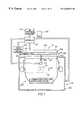
- FIG. 1is a view in elevation of a self-cleaning ink jet printer belonging to the present invention, the printer including a page-width print head;
- FIG. 2is a fragmentation view in vertical section of the print head, the print head defining a plurality of channels therein, each channel terminating in an orifice;
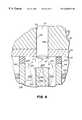
- FIG. 3is a fragmentation view in vertical section of the print head, this view showing some of the orifices encrusted with contaminant to be removed;
- FIG. 4is a view in elevation of a cleaning assembly for removing the contaminant
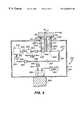
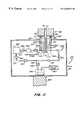
- FIG. 5is a view in vertical section of the cleaning assembly, the cleaning assembly including an oscillating septum disposed opposite the orifice so as to define a gap between the orifice and the septum and also including an ultrasonic transducer for generating pressure waves to remove the contaminant;
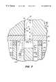
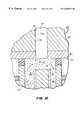
- FIG. 6is an enlarged fragmentation view in vertical section of the oscillating septum
- FIG. 7is an enlarged fragmentation view in vertical section of the cleaning assembly, this view showing the gap having reduced height due to increased length of the oscillating septum, for cleaning contaminant from within the ink channel;
- FIG. 8is an enlarged fragmentation view in vertical section of the cleaning assembly, this view showing the gap having increased width due to increased width of the oscillating septum, for cleaning contaminant from within the ink channel;
- FIG. 9is a view in vertical section of a second embodiment of the invention, wherein the cleaning assembly includes a pressurized gas supply in fluid communication with the gap for introducing gas bubbles into the liquid in the gap; and
- FIG. 10is an enlarged fragmentation view in vertical section of the second embodiment of the invention.
- FIG. 11is a view in vertical section of a fourth embodiment of the invention, wherein the cleaning assembly includes an expandable septum;
- FIG. 12is an enlarged fragmentation view in vertical section of expandable septum.
- FIG. 13is a view in vertical section of a fifth embodiment of the invention, wherein the septum is metallic and capable of moving under influence of a magnetic field established by electromagnets.
- a self-cleaning printerfor printing an image 20 on a receiver 30 , which may be a reflective-type receiver (e.g., paper) or a transmissive-type receiver (e.g., transparency).
- Receiver 30is supported on a platen roller 40 which is capable of being rotated by a platen roller motor 50 engaging platen roller 40 .
- platen roller motor 50rotates platen roller 40
- receiver 30will advance in a direction illustrated by a first arrow 55 .
- printer 10also comprises a “page-width” print head 60 disposed adjacent to platen roller 40 .
- Print head 60comprises a print head body 65 having a plurality of ink channels 70 , each channel 70 terminating in a channel outlet 75 .
- each channel 70which is adapted to hold an ink body 77 therein, is defined by a pair of oppositely disposed parallel side walls 79 a and 79 b .
- Attached, such as by a suitable adhesive, to print head body 65is a cover plate 80 having a plurality of orifices 85 formed therethrough colinearly aligned with respective ones of channel outlets 75 .
- a surface 90 of cover plate 80surrounds all orifices 85 and faces receiver 20 .
- print head body 65may be a “piezoelectric ink jet” print head body formed of a piezoelectric material, such as lead zirconium titanate (PZT).
- PZTlead zirconium titanate
- Such a piezoelectric materialis mechanically responsive to electrical stimuli so that side walls 79 a/b simultaneously inwardly deform when electrically stimulated.
- volume of channel 70decreases to squeeze ink droplet 100 from channel 70 .
- receiver 30is moved relative to page-width print head 60 by rotation of platen roller 40 , which is electronically controlled by paper transport control system 120 .
- Paper transport control system 120is in turn controlled by controller 130 .
- Paper transport control system 120 disclosed hereinis by way of example only, and many different configurations are possible based on the teachings herein. In the case of page-width print head 60 , it is more convenient to move receiver 30 past stationary head 60 .
- Controller 130which is connected to platen roller motor 50 , ink pressure regulator 110 and a cleaning assembly, enables the printing and print head cleaning operations. Structure and operation of the cleaning assembly is described in detail hereinbelow. Controller 130 may be a model CompuMotor controller available from Parker Hannifin in Rohrnert Park, Calif.
- Contaminant 140may be, for example, an oily film or particulate matter residing on surface 90 . Contaminant 140 also may partially or completely obstruct orifice 85 .
- the particulate mattermay be, for example, particles of dirt, dust, metal and/or encrustations of dried ink.
- the oily filmmay be, for example, grease or the like. Presence of contaminant 140 is undesirable because when contaminant 140 completely obstructs orifice 85 , ink droplet 100 is prevented from being ejected from orifice 85 .
- flight of ink droplet 100may be diverted from first axis 107 to travel along a second axis 145 (as shown). If ink droplet 100 travels along second axis 145 , ink droplet 100 will land on receiver 30 in an unintended location. In this manner, such complete or partial obstruction of orifice 85 leads to printing artifacts such as “banding”, a highly undesirable result. Also, presence of contaminant 140 may alter surface wetting and inhibit proper formation of droplet 100 . Therefore, it is desirable to clean (i.e., remove) contaminant 140 to avoid printing artifacts.
- a cleaning assemblyis disposed proximate surface 90 for directing a flow of cleaning liquid along surface 90 and across orifice 85 to clean contaminant 140 therefrom.
- Cleaning assembly 170is movable from a first or “rest” position 172 a spaced-apart from surface 90 to a second position 172 b engaging surface 90 . This movement is accomplished by means of an elevator 175 coupled to controller 130 .
- Cleaning assembly 170may comprise a housing 180 for reasons described presently. Disposed in housing 180 is a generally rectangular cup 190 having an open end 195 . Cup 190 defines a cavity 197 communicating with open end 195 .
- an elastomeric seal 200which may be rubber or the like, sized to encircle one or more orifices 85 and sealingly engage surface 90 .
- a structural membersuch as an elongate oscillatable septum 210 .
- septum 210is preferably made of a piezoelectric material, such as lead zirconate titanate (PZT). In this regard a mechanical stress is produced in the material when an applied electric field is applied.
- Septum 210has an end portion 215 which, when disposed opposite orifice 85 , defines a gap 220 of predetermined size between orifice 85 and end portion 215 . Moreover, end portion 215 of septum 210 may be disposed opposite a portion of surface 90 , not including orifice 85 , so that gap 220 is defined between surface 90 and end portion 215 . As described in more detail hereinbelow, gap 220 is sized to allow flow of a liquid therethrough in order to clean contaminant 140 from surface 90 and/or orifice 85 .
- transducers 218 a and 218 bare coupled to septum 210 near end portion 215 .
- transducers 218 a/bare metal plates capable of conducting electricity, thereby generating the electric field.
- transducers 218 a/bare connected to a suitable power source (not shown).
- a suitable power sourcenot shown.
- the end portion 215will bend in a preferred direction (as shown).
- two transducers 218 a/bare preferred, there may be only one transducer, if desired.
- the transducers 218 a/bare enabled sequentially (i.e., alternately). That is, when transducer 218 a is enabled, transducer 218 b is not enabled. Conversely, when transducer 218 b is enabled, transducer 218 a is not enabled. In this manner, the sequentially enabling transducers 218 a/b causes a oscillatory “to-and-fro motion” of the liquid in gap 200 . This to-and-fro motion of the liquid in turn causes a “sweeping” action which has been found to increase cleaning effectiveness.
- the frequency of the to-and-fro motionmay be between approximately 1 Hz and 5 MHz.
- the velocity of the liquid flowing through gap 220may be about 1 to 20 meters per second.
- height of gap 220may be approximately 3 to 30 thousandths of an inch.
- hydrodynamic pressure applied to contaminant 140 in gap 220 due, at least in part, to presence of septum 210may be approximately 1 to 30 psi (pounds per square inch).
- Septum 210partitions (i.e., divides) cavity 197 into an first chamber 230 and a second chamber 240 , for reasons described more fully hereinbelow.
- a pressure pulse generatorsuch as an ultrasonic transducer 245 , capable of generating a plurality of ultrasonic vibrations and therefore pressure waves 247 in the liquid.
- Pressure waves 247impact contaminant 140 to dislodge contaminant 140 from surface 90 and/or orifice 85 . It is believed pressure waves 247 accomplish this result by adding kinetic energy to the liquid along a vector directed substantially normal to surface 90 and orifices 85 .
- the liquidis substantially incompressible; therefore, pressure waves 247 propagate in the liquid in order to reach contaminant 140 .
- pressure waves 247may have a frequency of approximately 17,000 KHz and above.
- interconnecting first chamber 230 and second chamber 240is a closed-loop piping circuit 250 .
- piping circuit 250is in fluid communication with gap 220 for recycling the liquid through gap 220 .
- piping circuit 250comprises a first piping segment 260 extending from second chamber 240 to a reservoir 270 containing a supply of the liquid.
- Piping circuit 250further comprises a second piping segment 280 extending from reservoir 270 to first chamber 230 .
- Disposed in second piping segment 280is a recirculation pump 290 .
- Pump 290pumps the liquid from reservoir 270 , through second piping segment 280 , into first chamber 230 , through gap 220 , into second chamber 240 , through first piping segment 260 and back to reservoir 270 , as illustrated by a plurality of second arrows 295 .
- Disposed in first piping segment 260may be a first filter 300 and disposed in second piping segment 280 may be a second filter 310 for filtering (i.e., separating) contaminant 140 from the liquid as the liquid circulates through piping circuit 250 .
- portions of the piping circuit 250 adjacent to cup 190are preferably made of flexible tubing in order to facilitate uninhibited translation of cup 190 toward and away from print head 60 , which translation is accomplished by means of elevator 175 .
- a first valve 320is preferably disposed at a predetermined location in first piping segment 260 , which first valve 320 is operable to block flow of the liquid through first piping segment 260 .
- a second valve 330is preferably disposed at a predetermined location in second piping segment 280 , which second valve 330 is operable to block flow of the liquid through second piping segment 280 .
- first valve 320 and second valve 330are located in first piping segment 260 and second piping segment 280 , respectively, so as to isolate cavity 197 from reservoir 270 , for reasons described momentarily.
- a third piping segment 340has an open end thereof connected to first piping segment 260 and another open end thereof received into a sump 350 .
- a suction (i.e., vacuum) pump 360In communication with sump 350 is a suction (i.e., vacuum) pump 360 for reasons described presently.
- Suction pump 360drains cup 190 and associated piping of cleaning liquid before cup is detached and returned to first position 172 a .
- a third valve 370operable to isolate piping circuit 250 from sump 350 .
- first valve 320 and second valve 310are opened while third valve 370 is closed.
- Recirculation pump 290is then operated to draw the liquid from reservoir 270 and into first chamber 230 .
- the liquidwill then flow through gap 220 .
- a hydrodynamic shearing forcewill be induced in the liquid due to presence of end portion 215 of septum 210 . It is believed this shearing force is in turn caused by a hydrodynamic stress forming in the liquid, which stress has a “normal” component ⁇ n acting normal to surface 90 (or orifice 85 ) and a “shear” component ⁇ acting along surface 90 (or across orifice 85 ).
- FIG. 6Vectors representing the normal stress component ⁇ n and the shear stress component ⁇ are best seen in FIG. 6 .
- the previously mentioned hydrodynamic shearing force and pressure waves 247act on contaminant 140 to remove contaminant 140 from surface 90 and/or orifice 85 , so that contaminant 140 becomes entrained in the liquid flowing through gap 220 .
- transducers 218 a and 218 bare alternately enabled to produce the previously mentioned “sweeping” motion of end portion 215 of septum 210 . This sweeping motion in 30 turn causes the liquid in gap 220 to move back-and-forth to further loosen contaminant 140 . In this manner, cleaning effectiveness is enhanced.
- first filter 300 and second filter 310are provided for filtering contaminant 140 from the liquid recirculating through piping circuit 250 .
- recirculation pump 290is caused to cease operation and first valve 320 and second valve 330 are closed to isolate cavity 197 from reservoir 270 .
- third valve 370is opened and suction pump 360 is operated to substantially suction the liquid from first piping segment 260 , second piping segment 280 and cavity 197 .
- This suctioned liquidflows into sump 350 for later disposal.
- the liquid flowing into sump 350is substantially free of contaminant 140 due to presence of filters 300 / 310 and thus may be recycled into reservoir 270 , if desired.
- length and width of elongate septum 210controls amount of hydrodynamic stress acting against surface 90 and orifice 85 . This effect is important in order to control severity of cleaning action. Also, it has been discovered that, when end portion 215 of septum 210 is disposed opposite orifice 85 , length and width of elongate septum 210 controls amount of penetration (as shown) of the liquid into channel 70 . It is believed that control of penetration of the liquid into channel 70 is in turn a function of the amount of normal stress ⁇ n . However, it has been discovered that the amount of normal stress ⁇ n is inversely proportional to height of gap 220 .
- normal stress ⁇ nand thus amount of penetration of the liquid into channel 70 , can be increased by increasing length of septum 210 .
- amount of normal stress ⁇ nis directly proportional to pressure drop in the liquid as the liquid slides along end portion 215 and surface 90 . Therefore, normal stress ⁇ n , and thus amount of penetration of the liquid into channel 70 , can be increased by increasing width of septum 210 .
- These effectsare important in order to clean any contaminant 140 which may be adhering to either of side walls 79 a or 79 b . More specifically, when elongate septum 210 is fabricated so that it has a greater than nominal length X, height of gap 220 is decreased to enhance the cleaning action, if desired.
- elongate septum 210when elongate septum 210 is fabricated so that it has a greater than nominal width W, the run of gap 220 is increased to enhance the cleaning action, if desired.
- a person of ordinary skill in the artmay, without undue experimentation, vary both the length X and width W of septum 210 to obtain an optimum gap size for obtaining optimum cleaning depending on the amount and severity of contaminant encrustation. It may be appreciated from the discussion hereinabove, that a height H of seal 200 also may be varied to vary size of gap 220 with similar results.
- elevator 175may be connected to cleaning cup 190 for elevating cup l 90 so that seal 200 sealingly engages surface 90 when print head 60 is at second position 172 b .
- elevator 175is connected to controller 130 , so that operation of elevator 175 is controlled by controller 130 .
- elevator 175may be lowered so that seal no longer engages surface 90 .
- platen roller 40has to be moved to make room for cup 190 to engage print head 60 .
- An electronic signal from controller 130activates a motorized mechanism (not shown) that moves platen roller 40 in direction of first double-ended arrow 387 thus making room for upward movement of cup 190 .
- Controller 130also controls elevator 175 for transporting cup 190 from first position 172 a not engaging print head 60 to second position 172 b (shown in phantom) engaging print head 60 .
- cleaning assembly 170circulates liquid through cleaning cup 190 and over print head cover plate 80 .
- cup 190When print head 60 is required for printing, cup 190 is retracted into housing 180 by elevator 175 to its resting first position 172 a .
- the cup 190may be advanced outwardly from and retracted inwardly into housing 180 in direction of second double-ended arrow 388 .
- the liquid emerging from outlet chamber 240initially will be contaminated with contaminant 140 . It is desirable to collect this liquid in sump 350 rather than to recirculate the liquid. Therefore, this contaminated liquid is directed to sump 350 by closing second valve 330 and opening third valve 370 while suction pump 360 operates. The liquid will then be free of contaminant 140 and may be recirculated by closing third valve 370 and opening second valve 330 .
- a detector 397is disposed in first piping segment 260 to determine when the liquid is clean enough to be recirculated. Information from detector 397 can be processed and used to activate the valves in order to direct exiting liquid either into sump 350 or into recirculation.
- detector 397may be a spectrophotometric detector.
- suction pump 360is activated and third valve 370 is opened to suction into sump 350 any trapped liquid remaining between second valve 330 and first valve 320 .
- This processprevents spillage of liquid when cleaning assembly 170 is detached from cover plate 80 . Further, this process causes cover plate 80 to be substantially dry, thereby permitting print head 60 to function without impedance from cleaning liquid drops being around orifices 85 .
- sixth valve 430is closed and fifth valve 420 is opened to prime channel 70 with ink.
- Suction pump 360is again activated, and third valve 370 is opened to suction any liquid remaining in cup 190 .
- the cup 190may be detached and a separate spittoon (not shown) may be brought into alignment with print head 60 to collect drops of ink that are ejected from channel 70 during priming of print head 60 .
- print head 60may be rotated outwardly about a horizontal axis 389 to a convenient position to provide clearance for cup 190 to engage print head cover plate 80 .
- a pressurized gas supply 390is in communication with gap 220 for injecting a pressurized gas into gap 220 .
- the gaswill form a multiplicity of gas bubbles 395 in the liquid to enhance cleaning of contaminant 140 from surface 90 and/or orifice 85 .
- elongate septum 210has a bore 420 longitudinally therein.
- septum 210is preferably made of an elastomeric piezoelectric material, such as a rubber and PZT composition.
- a pneumatic pump 430for pumping a gas (e.g., air) into bore 420 .
- a gase.g., air
- elastic septum 210is pressurized so that septum 210 expands to greater width W and greater length X to obtain the enhanced cleaning effect described hereinabove.
- septum 210is expandable from a first volume thereof to a second volume greater than the first volume.
- a bleed valve 440is preferably provided. Bleed valve 440 is closed while pump 430 operates to expand elastic septum 210 . After the desired cleaning is achieved, pump 430 is caused to cease operation and bleed valve 440 is opened to release the gas from bore 420 . As the gas is released from bore 420 , septum 210 will return to its initial first volume.
- septum 210is formed of a metallic material so that septum 210 is movable under influence of a magnetic field.
- a pair of opposing electromagnets 450 a/bare attached to an inside wall of cavity 197 near end portion 215 of septum 210 .
- Magnets 450 a/bare sequentially enabled to sequentially generate an magnetic field acting on end portion 215 of septum 210 .
- end portion 215will be drawn to the magnet in order to obtain the previously mentioned “sweeping” motion of end portion 215 .
- this sweeping motionenhances cleaning effectiveness, as previously described.
- the cleaning liquidmay be any suitable liquid solvent composition, such as water, isopropanol, diethylene glycol, diethylene glycol monobutyl ether, octane, acids and bases, surfactant solutions and any combination thereof.
- suitable liquid solvent compositionssuch as water, isopropanol, diethylene glycol, diethylene glycol monobutyl ether, octane, acids and bases, surfactant solutions and any combination thereof.
- Complex liquid compositionsmay also be used, such as microemulsions, micellar surfactant solutions, vesicles and solid particles dispersed in the liquid.
- an advantage of the present inventionis that cleaning assembly 170 cleans contaminant 140 from surface 90 and/or orifice 85 without use of brushes or wipers which might otherwise damage surface 90 and/or orifice 85 . This is so because septum 210 induces shear stress in the liquid that flows through gap 220 to clean contaminant 140 from surface 90 and/or orifice 85 .
- another advantage of the present inventionis that cleaning efficiency is increased. This is so because operation of oscillating transducers 218 a/b induce to-and-fro motion of the cleaning fluid in the gap, thereby agitating the liquid coming into contact with contaminant 140 . Agitation of the liquid in this manner in turn agitates contaminant 140 in order to loosen contaminant 140 .
- a heatermay be disposed in reservoir 270 to heat the liquid therein for enhancing cleaning of surface 90 , channel 70 and/or orifice 85 . This is particularly useful when the cleaning liquid is of a type that increases in cleaning effectiveness as temperature of the liquid is increased.
- a contamination sensormay be connected to cleaning assembly 170 for detecting when cleaning is needed.
- a contamination sensormay a pressure transducer in fluid communication with ink in channels 70 for detecting rise in ink back pressure when partially or completely blocked channels 70 attempt to eject ink droplets 100 .
- Such a contamination sensormay also be a flow detector in communication with ink in channels 70 to detect low ink flow when partially or completely blocked channels 70 attempt to eject ink droplets 100 .
- Such a contamination sensormay also be an optical detector in optical communication with surface 90 and orifices 85 to optically detect presence of contaminant 140 by means of reflection or emissivity.
- Such a contamination sensormay also be a device measuring amount of ink released into a spittoon-like container during predetermined periodic purging of channels 70 . In this case, the amount of ink released into the spittoon-like container would be measured by the device and compared against a known amount of ink that should be present in the spittoon-like container if no orifices were blocked by contaminant 140 .
- controller 130may drive other auxiliary functions.
Landscapes
- Ink Jet (AREA)
- Details Or Accessories Of Spraying Plant Or Apparatus (AREA)
- Coating Apparatus (AREA)
Abstract
Description
Claims (56)
Priority Applications (4)
| Application Number | Priority Date | Filing Date | Title |
|---|---|---|---|
| US09/222,409US6286929B1 (en) | 1998-12-29 | 1998-12-29 | Self-cleaning ink jet printer with oscillating septum and ultrasonics and method of assembling the printer |
| DE69911365TDE69911365T2 (en) | 1998-12-29 | 1999-12-13 | Self-cleaning inkjet printer with vibrating membrane and method of operating the printer |
| EP99204276AEP1016531B1 (en) | 1998-12-29 | 1999-12-13 | A self-cleaning ink jet printer with oscillating septum and method of operating the printer |
| JP11368418AJP2000229416A (en) | 1998-12-29 | 1999-12-24 | Ultrasonic self-cleaning ink jet printer with oscillation barrier wall and assembling method thereof |
Applications Claiming Priority (1)
| Application Number | Priority Date | Filing Date | Title |
|---|---|---|---|
| US09/222,409US6286929B1 (en) | 1998-12-29 | 1998-12-29 | Self-cleaning ink jet printer with oscillating septum and ultrasonics and method of assembling the printer |
Publications (1)
| Publication Number | Publication Date |
|---|---|
| US6286929B1true US6286929B1 (en) | 2001-09-11 |
Family
ID=22832062
Family Applications (1)
| Application Number | Title | Priority Date | Filing Date |
|---|---|---|---|
| US09/222,409Expired - LifetimeUS6286929B1 (en) | 1998-12-29 | 1998-12-29 | Self-cleaning ink jet printer with oscillating septum and ultrasonics and method of assembling the printer |
Country Status (4)
| Country | Link |
|---|---|
| US (1) | US6286929B1 (en) |
| EP (1) | EP1016531B1 (en) |
| JP (1) | JP2000229416A (en) |
| DE (1) | DE69911365T2 (en) |
Cited By (14)
| Publication number | Priority date | Publication date | Assignee | Title |
|---|---|---|---|---|
| US6660103B1 (en) | 2002-03-28 | 2003-12-09 | Vutek, Inc. | Cleaning process for ink jet printheads |
| US20060055726A1 (en)* | 2004-09-15 | 2006-03-16 | Eastman Kodak Company | Method for removing liquid in the gap of a printhead |
| US7291002B2 (en) | 2003-05-23 | 2007-11-06 | Z Corporation | Apparatus and methods for 3D printing |
| US7435368B2 (en) | 1996-12-20 | 2008-10-14 | Z Corporation | Three-dimensional printer |
| US20080316251A1 (en)* | 2007-06-21 | 2008-12-25 | Samsung Electronics Co., Ltd. | Print head cleaning device and ink-jet image forming apparatus having the same |
| US20090121038A1 (en)* | 2005-05-06 | 2009-05-14 | Dieter Wurz | Spray nozzle, spray device and method for operating a spray nozzle and a spray device |
| US20090273621A1 (en)* | 2008-05-01 | 2009-11-05 | Folkers John P | System and method for maintaining or recovering nozzle function for an inkjet printhead |
| US7686995B2 (en) | 1996-12-20 | 2010-03-30 | Z Corporation | Three-dimensional printer |
| US7828022B2 (en) | 2006-05-26 | 2010-11-09 | Z Corporation | Apparatus and methods for handling materials in a 3-D printer |
| US9090113B1 (en)* | 2014-03-31 | 2015-07-28 | Xerox Corporation | System for detecting inoperative ejectors in three-dimensional object printing using a pneumatic sensor |
| US20160349157A1 (en)* | 2015-05-26 | 2016-12-01 | Intellectual Reserves, LLC | System and Method for Repeatable Fluid Measurements |
| EP2955027A4 (en)* | 2013-02-08 | 2016-12-14 | Personas Y Tecnología S L | EQUIPMENT AND METHOD FOR CLEANING INK INJECTION PRINTING HEADS |
| US20180104960A1 (en)* | 2016-05-11 | 2018-04-19 | BOE Technology Group Co.,Ltd. | Ink measuring system and printing device |
| US20220040982A1 (en)* | 2020-08-06 | 2022-02-10 | Semes Co., Ltd. | Head cleaning unit and substrate treating apparatus |
Families Citing this family (5)
| Publication number | Priority date | Publication date | Assignee | Title |
|---|---|---|---|---|
| KR100431007B1 (en)* | 2001-12-03 | 2004-05-12 | 삼성전자주식회사 | maintenance apparatus of an ink-jet printer having a vaporizer |
| JP4867472B2 (en)* | 2006-05-25 | 2012-02-01 | 凸版印刷株式会社 | Micro dispenser type color correction device |
| JP4864617B2 (en)* | 2006-09-21 | 2012-02-01 | 株式会社東芝 | Cleaning liquid and nozzle plate cleaning method |
| KR100986804B1 (en)* | 2008-05-21 | 2010-10-08 | 한양대학교 산학협력단 | Blocking device for single nozzle head |
| CN114589071B (en)* | 2022-04-04 | 2022-12-13 | 南通市通州忠义纺织机械有限公司 | Novel backflow device for coating machine |
Citations (33)
| Publication number | Priority date | Publication date | Assignee | Title |
|---|---|---|---|---|
| US3373437A (en) | 1964-03-25 | 1968-03-12 | Richard G. Sweet | Fluid droplet recorder with a plurality of jets |
| US3416153A (en) | 1965-10-08 | 1968-12-10 | Hertz | Ink jet recorder |
| US3705043A (en) | 1970-12-07 | 1972-12-05 | Dick Co Ab | Infrared absorptive jet printing ink composition |
| US3776642A (en) | 1972-08-01 | 1973-12-04 | Dickey John Corp | Grain analysis computer |
| US3846141A (en) | 1970-12-07 | 1974-11-05 | Dick Co Ab | Jet printing ink composition |
| US3870528A (en) | 1973-12-17 | 1975-03-11 | Ibm | Infrared and visible dual dye jet printer ink |
| US3878519A (en) | 1974-01-31 | 1975-04-15 | Ibm | Method and apparatus for synchronizing droplet formation in a liquid stream |
| US3889269A (en) | 1972-12-01 | 1975-06-10 | Agfa Gevaert Ag | Aqueous ink for use in the ink jet process |
| US3903034A (en) | 1970-12-07 | 1975-09-02 | Dick Co Ab | Offset jet printing ink |
| US4346387A (en) | 1979-12-07 | 1982-08-24 | Hertz Carl H | Method and apparatus for controlling the electric charge on droplets and ink-jet recorder incorporating the same |
| US4354197A (en)* | 1980-10-03 | 1982-10-12 | Ncr Corporation | Ink jet printer drive means |
| US4591870A (en) | 1985-04-12 | 1986-05-27 | Eastman Kodak Company | Ink jet printing apparatus and method with condensate-washing for print head |
| US4600928A (en) | 1985-04-12 | 1986-07-15 | Eastman Kodak Company | Ink jet printing apparatus having ultrasonic print head cleaning system |
| JPS62113555A (en) | 1985-11-13 | 1987-05-25 | Canon Inc | Ink jet recorder |
| EP0292779A1 (en) | 1987-05-25 | 1988-11-30 | Siemens Aktiengesellschaft | Method and device for cleaning elements with cavities |
| US4849769A (en) | 1987-06-02 | 1989-07-18 | Burlington Industries, Inc. | System for ultrasonic cleaning of ink jet orifices |
| US4908636A (en)* | 1987-03-31 | 1990-03-13 | Canon Kabushiki Kaisha | Recovery device having a protruding portion providing reduced pressure for improved recovery and method using same |
| JPH02235764A (en)* | 1989-03-10 | 1990-09-18 | Canon Inc | Ink jet recorder |
| US4970535A (en) | 1988-09-26 | 1990-11-13 | Tektronix, Inc. | Ink jet print head face cleaner |
| US5115250A (en) | 1990-01-12 | 1992-05-19 | Hewlett-Packard Company | Wiper for ink-jet printhead |
| US5148746A (en) | 1988-08-19 | 1992-09-22 | Presstek, Inc. | Print-head and plate-cleaning assembly |
| US5305015A (en) | 1990-08-16 | 1994-04-19 | Hewlett-Packard Company | Laser ablated nozzle member for inkjet printhead |
| US5325111A (en)* | 1992-12-28 | 1994-06-28 | Xerox Corporation | Removing waste ink from capping station |
| US5350616A (en) | 1993-06-16 | 1994-09-27 | Hewlett-Packard Company | Composite orifice plate for ink jet printer and method for the manufacture thereof |
| US5412441A (en)* | 1994-03-07 | 1995-05-02 | Tibbling; Lars | Keratometer device having photographically produced bore pattern |
| US5426458A (en) | 1993-08-09 | 1995-06-20 | Hewlett-Packard Corporation | Poly-p-xylylene films as an orifice plate coating |
| US5431722A (en) | 1992-12-01 | 1995-07-11 | Fuji Xerox Co., Ltd. | Ink for inkjet printing |
| US5559538A (en)* | 1994-08-12 | 1996-09-24 | Hewlett-Packard Company | Positioning of service station and paper pick pressure plate using single motor |
| US5574485A (en) | 1994-10-13 | 1996-11-12 | Xerox Corporation | Ultrasonic liquid wiper for ink jet printhead maintenance |
| US5725647A (en) | 1996-11-27 | 1998-03-10 | Minnesota Mining And Manufacturing Company | Pigmented inks and humectants used therewith |
| US5738716A (en) | 1996-08-20 | 1998-04-14 | Eastman Kodak Company | Color pigmented ink jet ink set |
| US5774140A (en) | 1995-10-31 | 1998-06-30 | Hewlett-Packard Company | Skip stroke wiping system for inkjet printheads |
| US5997127A (en)* | 1998-09-24 | 1999-12-07 | Eastman Kodak Company | Adjustable vane used in cleaning orifices in inkjet printing apparatus |
- 1998
- 1998-12-29USUS09/222,409patent/US6286929B1/ennot_activeExpired - Lifetime
- 1999
- 1999-12-13EPEP99204276Apatent/EP1016531B1/ennot_activeExpired - Lifetime
- 1999-12-13DEDE69911365Tpatent/DE69911365T2/ennot_activeExpired - Fee Related
- 1999-12-24JPJP11368418Apatent/JP2000229416A/enactivePending
Patent Citations (33)
| Publication number | Priority date | Publication date | Assignee | Title |
|---|---|---|---|---|
| US3373437A (en) | 1964-03-25 | 1968-03-12 | Richard G. Sweet | Fluid droplet recorder with a plurality of jets |
| US3416153A (en) | 1965-10-08 | 1968-12-10 | Hertz | Ink jet recorder |
| US3903034A (en) | 1970-12-07 | 1975-09-02 | Dick Co Ab | Offset jet printing ink |
| US3705043A (en) | 1970-12-07 | 1972-12-05 | Dick Co Ab | Infrared absorptive jet printing ink composition |
| US3846141A (en) | 1970-12-07 | 1974-11-05 | Dick Co Ab | Jet printing ink composition |
| US3776642A (en) | 1972-08-01 | 1973-12-04 | Dickey John Corp | Grain analysis computer |
| US3889269A (en) | 1972-12-01 | 1975-06-10 | Agfa Gevaert Ag | Aqueous ink for use in the ink jet process |
| US3870528A (en) | 1973-12-17 | 1975-03-11 | Ibm | Infrared and visible dual dye jet printer ink |
| US3878519A (en) | 1974-01-31 | 1975-04-15 | Ibm | Method and apparatus for synchronizing droplet formation in a liquid stream |
| US4346387A (en) | 1979-12-07 | 1982-08-24 | Hertz Carl H | Method and apparatus for controlling the electric charge on droplets and ink-jet recorder incorporating the same |
| US4354197A (en)* | 1980-10-03 | 1982-10-12 | Ncr Corporation | Ink jet printer drive means |
| US4591870A (en) | 1985-04-12 | 1986-05-27 | Eastman Kodak Company | Ink jet printing apparatus and method with condensate-washing for print head |
| US4600928A (en) | 1985-04-12 | 1986-07-15 | Eastman Kodak Company | Ink jet printing apparatus having ultrasonic print head cleaning system |
| JPS62113555A (en) | 1985-11-13 | 1987-05-25 | Canon Inc | Ink jet recorder |
| US4908636A (en)* | 1987-03-31 | 1990-03-13 | Canon Kabushiki Kaisha | Recovery device having a protruding portion providing reduced pressure for improved recovery and method using same |
| EP0292779A1 (en) | 1987-05-25 | 1988-11-30 | Siemens Aktiengesellschaft | Method and device for cleaning elements with cavities |
| US4849769A (en) | 1987-06-02 | 1989-07-18 | Burlington Industries, Inc. | System for ultrasonic cleaning of ink jet orifices |
| US5148746A (en) | 1988-08-19 | 1992-09-22 | Presstek, Inc. | Print-head and plate-cleaning assembly |
| US4970535A (en) | 1988-09-26 | 1990-11-13 | Tektronix, Inc. | Ink jet print head face cleaner |
| JPH02235764A (en)* | 1989-03-10 | 1990-09-18 | Canon Inc | Ink jet recorder |
| US5115250A (en) | 1990-01-12 | 1992-05-19 | Hewlett-Packard Company | Wiper for ink-jet printhead |
| US5305015A (en) | 1990-08-16 | 1994-04-19 | Hewlett-Packard Company | Laser ablated nozzle member for inkjet printhead |
| US5431722A (en) | 1992-12-01 | 1995-07-11 | Fuji Xerox Co., Ltd. | Ink for inkjet printing |
| US5325111A (en)* | 1992-12-28 | 1994-06-28 | Xerox Corporation | Removing waste ink from capping station |
| US5350616A (en) | 1993-06-16 | 1994-09-27 | Hewlett-Packard Company | Composite orifice plate for ink jet printer and method for the manufacture thereof |
| US5426458A (en) | 1993-08-09 | 1995-06-20 | Hewlett-Packard Corporation | Poly-p-xylylene films as an orifice plate coating |
| US5412441A (en)* | 1994-03-07 | 1995-05-02 | Tibbling; Lars | Keratometer device having photographically produced bore pattern |
| US5559538A (en)* | 1994-08-12 | 1996-09-24 | Hewlett-Packard Company | Positioning of service station and paper pick pressure plate using single motor |
| US5574485A (en) | 1994-10-13 | 1996-11-12 | Xerox Corporation | Ultrasonic liquid wiper for ink jet printhead maintenance |
| US5774140A (en) | 1995-10-31 | 1998-06-30 | Hewlett-Packard Company | Skip stroke wiping system for inkjet printheads |
| US5738716A (en) | 1996-08-20 | 1998-04-14 | Eastman Kodak Company | Color pigmented ink jet ink set |
| US5725647A (en) | 1996-11-27 | 1998-03-10 | Minnesota Mining And Manufacturing Company | Pigmented inks and humectants used therewith |
| US5997127A (en)* | 1998-09-24 | 1999-12-07 | Eastman Kodak Company | Adjustable vane used in cleaning orifices in inkjet printing apparatus |
Cited By (23)
| Publication number | Priority date | Publication date | Assignee | Title |
|---|---|---|---|---|
| US7435368B2 (en) | 1996-12-20 | 2008-10-14 | Z Corporation | Three-dimensional printer |
| US7686995B2 (en) | 1996-12-20 | 2010-03-30 | Z Corporation | Three-dimensional printer |
| US8017055B2 (en) | 1996-12-20 | 2011-09-13 | Z Corporation | Three-dimensional printer |
| US6660103B1 (en) | 2002-03-28 | 2003-12-09 | Vutek, Inc. | Cleaning process for ink jet printheads |
| US7291002B2 (en) | 2003-05-23 | 2007-11-06 | Z Corporation | Apparatus and methods for 3D printing |
| US20060055726A1 (en)* | 2004-09-15 | 2006-03-16 | Eastman Kodak Company | Method for removing liquid in the gap of a printhead |
| US7178897B2 (en) | 2004-09-15 | 2007-02-20 | Eastman Kodak Company | Method for removing liquid in the gap of a printhead |
| US8985478B2 (en) | 2005-05-06 | 2015-03-24 | Dieter Wurz | Spray nozzle, spray device and method for operating a spray nozzle and a spray device |
| US20090121038A1 (en)* | 2005-05-06 | 2009-05-14 | Dieter Wurz | Spray nozzle, spray device and method for operating a spray nozzle and a spray device |
| US8453945B2 (en) | 2005-05-06 | 2013-06-04 | Dieter Wurz | Spray nozzle, spray device and method for operating a spray nozzle and a spray device |
| US7971991B2 (en) | 2006-05-26 | 2011-07-05 | Z Corporation | Apparatus and methods for handling materials in a 3-D printer |
| US7979152B2 (en) | 2006-05-26 | 2011-07-12 | Z Corporation | Apparatus and methods for handling materials in a 3-D printer |
| US7828022B2 (en) | 2006-05-26 | 2010-11-09 | Z Corporation | Apparatus and methods for handling materials in a 3-D printer |
| US8185229B2 (en) | 2006-05-26 | 2012-05-22 | 3D Systems, Inc. | Apparatus and methods for handling materials in a 3-D printer |
| US20080316251A1 (en)* | 2007-06-21 | 2008-12-25 | Samsung Electronics Co., Ltd. | Print head cleaning device and ink-jet image forming apparatus having the same |
| US8113613B2 (en) | 2008-05-01 | 2012-02-14 | Videojet Technologies Inc. | System and method for maintaining or recovering nozzle function for an inkjet printhead |
| US20090273621A1 (en)* | 2008-05-01 | 2009-11-05 | Folkers John P | System and method for maintaining or recovering nozzle function for an inkjet printhead |
| EP2955027A4 (en)* | 2013-02-08 | 2016-12-14 | Personas Y Tecnología S L | EQUIPMENT AND METHOD FOR CLEANING INK INJECTION PRINTING HEADS |
| US9090113B1 (en)* | 2014-03-31 | 2015-07-28 | Xerox Corporation | System for detecting inoperative ejectors in three-dimensional object printing using a pneumatic sensor |
| US20160349157A1 (en)* | 2015-05-26 | 2016-12-01 | Intellectual Reserves, LLC | System and Method for Repeatable Fluid Measurements |
| US9869227B2 (en)* | 2015-05-26 | 2018-01-16 | Intellectual Reserves, LLC | System and method for repeatable fluid measurements |
| US20180104960A1 (en)* | 2016-05-11 | 2018-04-19 | BOE Technology Group Co.,Ltd. | Ink measuring system and printing device |
| US20220040982A1 (en)* | 2020-08-06 | 2022-02-10 | Semes Co., Ltd. | Head cleaning unit and substrate treating apparatus |
Also Published As
| Publication number | Publication date |
|---|---|
| DE69911365D1 (en) | 2003-10-23 |
| EP1016531A1 (en) | 2000-07-05 |
| EP1016531B1 (en) | 2003-09-17 |
| JP2000229416A (en) | 2000-08-22 |
| DE69911365T2 (en) | 2004-07-22 |
Similar Documents
| Publication | Publication Date | Title |
|---|---|---|
| US6350007B1 (en) | Self-cleaning ink jet printer using ultrasonics and method of assembling same | |
| EP1005997B1 (en) | A self-cleaning ink jet printer with reverse flow and method of assembling the printer | |
| US6286929B1 (en) | Self-cleaning ink jet printer with oscillating septum and ultrasonics and method of assembling the printer | |
| US6290323B1 (en) | Self-cleaning ink jet printer system with reverse fluid flow and rotating roller and method of assembling the printer system | |
| US6183058B1 (en) | Self-cleaning ink jet printer system with reverse fluid flow and method of assembling the printer system | |
| US6183057B1 (en) | Self-cleaning ink jet printer having ultrasonics with reverse flow and method of assembling same | |
| US6513903B2 (en) | Ink jet print head with capillary flow cleaning | |
| US6168256B1 (en) | Self-cleaning ink jet printer with oscillating septum and method of assembling the printer | |
| US6406122B1 (en) | Method and cleaning assembly for cleaning an ink jet print head in a self-cleaning ink jet printer system | |
| EP1060894B1 (en) | Multi-fluidic cleaning for ink jet print heads | |
| US6241337B1 (en) | Ink jet printer with cleaning mechanism having a wiper blade and transducer and method of assembling the printer | |
| US6283575B1 (en) | Ink printing head with gutter cleaning structure and method of assembling the printer | |
| US6595617B2 (en) | Self-cleaning printer and print head and method for manufacturing same | |
| US6497472B2 (en) | Self-cleaning ink jet printer and print head with cleaning fluid flow system | |
| US6145952A (en) | Self-cleaning ink jet printer and method of assembling same |
Legal Events
| Date | Code | Title | Description |
|---|---|---|---|
| AS | Assignment | Owner name:EASTMAN KODAK COMPANY, NEW YORK Free format text:ASSIGNMENT OF ASSIGNORS INTEREST;ASSIGNORS:SHARMA, RAVI;QUENIN, JOHN A.;DELAMETTER, CHRISTOPHER N.;AND OTHERS;REEL/FRAME:009800/0165;SIGNING DATES FROM 19990218 TO 19990301 | |
| FEPP | Fee payment procedure | Free format text:PAYOR NUMBER ASSIGNED (ORIGINAL EVENT CODE: ASPN); ENTITY STATUS OF PATENT OWNER: LARGE ENTITY | |
| STCF | Information on status: patent grant | Free format text:PATENTED CASE | |
| FPAY | Fee payment | Year of fee payment:4 | |
| FPAY | Fee payment | Year of fee payment:8 | |
| AS | Assignment | Owner name:CITICORP NORTH AMERICA, INC., AS AGENT, NEW YORK Free format text:SECURITY INTEREST;ASSIGNORS:EASTMAN KODAK COMPANY;PAKON, INC.;REEL/FRAME:028201/0420 Effective date:20120215 | |
| FPAY | Fee payment | Year of fee payment:12 | |
| AS | Assignment | Owner name:WILMINGTON TRUST, NATIONAL ASSOCIATION, AS AGENT, MINNESOTA Free format text:PATENT SECURITY AGREEMENT;ASSIGNORS:EASTMAN KODAK COMPANY;PAKON, INC.;REEL/FRAME:030122/0235 Effective date:20130322 Owner name:WILMINGTON TRUST, NATIONAL ASSOCIATION, AS AGENT, Free format text:PATENT SECURITY AGREEMENT;ASSIGNORS:EASTMAN KODAK COMPANY;PAKON, INC.;REEL/FRAME:030122/0235 Effective date:20130322 | |
| AS | Assignment | Owner name:BANK OF AMERICA N.A., AS AGENT, MASSACHUSETTS Free format text:INTELLECTUAL PROPERTY SECURITY AGREEMENT (ABL);ASSIGNORS:EASTMAN KODAK COMPANY;FAR EAST DEVELOPMENT LTD.;FPC INC.;AND OTHERS;REEL/FRAME:031162/0117 Effective date:20130903 Owner name:JPMORGAN CHASE BANK, N.A., AS ADMINISTRATIVE, DELAWARE Free format text:INTELLECTUAL PROPERTY SECURITY AGREEMENT (FIRST LIEN);ASSIGNORS:EASTMAN KODAK COMPANY;FAR EAST DEVELOPMENT LTD.;FPC INC.;AND OTHERS;REEL/FRAME:031158/0001 Effective date:20130903 Owner name:BARCLAYS BANK PLC, AS ADMINISTRATIVE AGENT, NEW YORK Free format text:INTELLECTUAL PROPERTY SECURITY AGREEMENT (SECOND LIEN);ASSIGNORS:EASTMAN KODAK COMPANY;FAR EAST DEVELOPMENT LTD.;FPC INC.;AND OTHERS;REEL/FRAME:031159/0001 Effective date:20130903 Owner name:BARCLAYS BANK PLC, AS ADMINISTRATIVE AGENT, NEW YO Free format text:INTELLECTUAL PROPERTY SECURITY AGREEMENT (SECOND LIEN);ASSIGNORS:EASTMAN KODAK COMPANY;FAR EAST DEVELOPMENT LTD.;FPC INC.;AND OTHERS;REEL/FRAME:031159/0001 Effective date:20130903 Owner name:EASTMAN KODAK COMPANY, NEW YORK Free format text:RELEASE OF SECURITY INTEREST IN PATENTS;ASSIGNORS:CITICORP NORTH AMERICA, INC., AS SENIOR DIP AGENT;WILMINGTON TRUST, NATIONAL ASSOCIATION, AS JUNIOR DIP AGENT;REEL/FRAME:031157/0451 Effective date:20130903 Owner name:PAKON, INC., NEW YORK Free format text:RELEASE OF SECURITY INTEREST IN PATENTS;ASSIGNORS:CITICORP NORTH AMERICA, INC., AS SENIOR DIP AGENT;WILMINGTON TRUST, NATIONAL ASSOCIATION, AS JUNIOR DIP AGENT;REEL/FRAME:031157/0451 Effective date:20130903 Owner name:JPMORGAN CHASE BANK, N.A., AS ADMINISTRATIVE, DELA Free format text:INTELLECTUAL PROPERTY SECURITY AGREEMENT (FIRST LIEN);ASSIGNORS:EASTMAN KODAK COMPANY;FAR EAST DEVELOPMENT LTD.;FPC INC.;AND OTHERS;REEL/FRAME:031158/0001 Effective date:20130903 | |
| AS | Assignment | Owner name:NPEC, INC., NEW YORK Free format text:RELEASE BY SECURED PARTY;ASSIGNOR:JP MORGAN CHASE BANK, N.A., AS ADMINISTRATIVE AGENT;REEL/FRAME:049814/0001 Effective date:20190617 Owner name:PAKON, INC., NEW YORK Free format text:RELEASE BY SECURED PARTY;ASSIGNOR:JP MORGAN CHASE BANK, N.A., AS ADMINISTRATIVE AGENT;REEL/FRAME:049814/0001 Effective date:20190617 Owner name:CREO MANUFACTURING AMERICA LLC, NEW YORK Free format text:RELEASE BY SECURED PARTY;ASSIGNOR:JP MORGAN CHASE BANK, N.A., AS ADMINISTRATIVE AGENT;REEL/FRAME:049814/0001 Effective date:20190617 Owner name:FAR EAST DEVELOPMENT LTD., NEW YORK Free format text:RELEASE BY SECURED PARTY;ASSIGNOR:JP MORGAN CHASE BANK, N.A., AS ADMINISTRATIVE AGENT;REEL/FRAME:049814/0001 Effective date:20190617 Owner name:LASER PACIFIC MEDIA CORPORATION, NEW YORK Free format text:RELEASE BY SECURED PARTY;ASSIGNOR:JP MORGAN CHASE BANK, N.A., AS ADMINISTRATIVE AGENT;REEL/FRAME:049814/0001 Effective date:20190617 Owner name:KODAK PORTUGUESA LIMITED, NEW YORK Free format text:RELEASE BY SECURED PARTY;ASSIGNOR:JP MORGAN CHASE BANK, N.A., AS ADMINISTRATIVE AGENT;REEL/FRAME:049814/0001 Effective date:20190617 Owner name:KODAK PHILIPPINES, LTD., NEW YORK Free format text:RELEASE BY SECURED PARTY;ASSIGNOR:JP MORGAN CHASE BANK, N.A., AS ADMINISTRATIVE AGENT;REEL/FRAME:049814/0001 Effective date:20190617 Owner name:KODAK (NEAR EAST), INC., NEW YORK Free format text:RELEASE BY SECURED PARTY;ASSIGNOR:JP MORGAN CHASE BANK, N.A., AS ADMINISTRATIVE AGENT;REEL/FRAME:049814/0001 Effective date:20190617 Owner name:KODAK IMAGING NETWORK, INC., NEW YORK Free format text:RELEASE BY SECURED PARTY;ASSIGNOR:JP MORGAN CHASE BANK, N.A., AS ADMINISTRATIVE AGENT;REEL/FRAME:049814/0001 Effective date:20190617 Owner name:EASTMAN KODAK COMPANY, NEW YORK Free format text:RELEASE BY SECURED PARTY;ASSIGNOR:JP MORGAN CHASE BANK, N.A., AS ADMINISTRATIVE AGENT;REEL/FRAME:049814/0001 Effective date:20190617 Owner name:FPC, INC., NEW YORK Free format text:RELEASE BY SECURED PARTY;ASSIGNOR:JP MORGAN CHASE BANK, N.A., AS ADMINISTRATIVE AGENT;REEL/FRAME:049814/0001 Effective date:20190617 Owner name:KODAK AMERICAS, LTD., NEW YORK Free format text:RELEASE BY SECURED PARTY;ASSIGNOR:JP MORGAN CHASE BANK, N.A., AS ADMINISTRATIVE AGENT;REEL/FRAME:049814/0001 Effective date:20190617 Owner name:KODAK AVIATION LEASING LLC, NEW YORK Free format text:RELEASE BY SECURED PARTY;ASSIGNOR:JP MORGAN CHASE BANK, N.A., AS ADMINISTRATIVE AGENT;REEL/FRAME:049814/0001 Effective date:20190617 Owner name:KODAK REALTY, INC., NEW YORK Free format text:RELEASE BY SECURED PARTY;ASSIGNOR:JP MORGAN CHASE BANK, N.A., AS ADMINISTRATIVE AGENT;REEL/FRAME:049814/0001 Effective date:20190617 Owner name:QUALEX, INC., NEW YORK Free format text:RELEASE BY SECURED PARTY;ASSIGNOR:JP MORGAN CHASE BANK, N.A., AS ADMINISTRATIVE AGENT;REEL/FRAME:049814/0001 Effective date:20190617 | |
| AS | Assignment | Owner name:NPEC INC., NEW YORK Free format text:RELEASE BY SECURED PARTY;ASSIGNOR:BARCLAYS BANK PLC;REEL/FRAME:052773/0001 Effective date:20170202 Owner name:QUALEX INC., NEW YORK Free format text:RELEASE BY SECURED PARTY;ASSIGNOR:BARCLAYS BANK PLC;REEL/FRAME:052773/0001 Effective date:20170202 Owner name:FAR EAST DEVELOPMENT LTD., NEW YORK Free format text:RELEASE BY SECURED PARTY;ASSIGNOR:BARCLAYS BANK PLC;REEL/FRAME:052773/0001 Effective date:20170202 Owner name:KODAK AMERICAS LTD., NEW YORK Free format text:RELEASE BY SECURED PARTY;ASSIGNOR:BARCLAYS BANK PLC;REEL/FRAME:052773/0001 Effective date:20170202 Owner name:LASER PACIFIC MEDIA CORPORATION, NEW YORK Free format text:RELEASE BY SECURED PARTY;ASSIGNOR:BARCLAYS BANK PLC;REEL/FRAME:052773/0001 Effective date:20170202 Owner name:KODAK (NEAR EAST) INC., NEW YORK Free format text:RELEASE BY SECURED PARTY;ASSIGNOR:BARCLAYS BANK PLC;REEL/FRAME:052773/0001 Effective date:20170202 Owner name:EASTMAN KODAK COMPANY, NEW YORK Free format text:RELEASE BY SECURED PARTY;ASSIGNOR:BARCLAYS BANK PLC;REEL/FRAME:052773/0001 Effective date:20170202 Owner name:KODAK PHILIPPINES LTD., NEW YORK Free format text:RELEASE BY SECURED PARTY;ASSIGNOR:BARCLAYS BANK PLC;REEL/FRAME:052773/0001 Effective date:20170202 Owner name:KODAK REALTY INC., NEW YORK Free format text:RELEASE BY SECURED PARTY;ASSIGNOR:BARCLAYS BANK PLC;REEL/FRAME:052773/0001 Effective date:20170202 Owner name:FPC INC., NEW YORK Free format text:RELEASE BY SECURED PARTY;ASSIGNOR:BARCLAYS BANK PLC;REEL/FRAME:052773/0001 Effective date:20170202 |