US6286675B1 - Blade disposal apparatus and holder unit - Google Patents
Blade disposal apparatus and holder unitDownload PDFInfo
- Publication number
- US6286675B1 US6286675B1US09/493,316US49331600AUS6286675B1US 6286675 B1US6286675 B1US 6286675B1US 49331600 AUS49331600 AUS 49331600AUS 6286675 B1US6286675 B1US 6286675B1
- Authority
- US
- United States
- Prior art keywords
- blade
- housing
- unit
- blade disposal
- receive
- Prior art date
- Legal status (The legal status is an assumption and is not a legal conclusion. Google has not performed a legal analysis and makes no representation as to the accuracy of the status listed.)
- Expired - Lifetime
Links
- 239000000463materialSubstances0.000description3
- 230000007246mechanismEffects0.000description3
- 239000004743PolypropyleneSubstances0.000description2
- 208000027418Wounds and injuryDiseases0.000description2
- 238000007792additionMethods0.000description2
- 230000006378damageEffects0.000description2
- 208000014674injuryDiseases0.000description2
- 238000012986modificationMethods0.000description2
- 230000004048modificationEffects0.000description2
- 239000004033plasticSubstances0.000description2
- -1polypropylenePolymers0.000description2
- 229920001155polypropylenePolymers0.000description2
- 229920005992thermoplastic resinPolymers0.000description2
- XAGFODPZIPBFFR-UHFFFAOYSA-NaluminiumChemical compound[Al]XAGFODPZIPBFFR-UHFFFAOYSA-N0.000description1
- 229910052782aluminiumInorganic materials0.000description1
- 238000000071blow mouldingMethods0.000description1
- 230000000295complement effectEffects0.000description1
- 230000007423decreaseEffects0.000description1
- 210000003811fingerAnatomy0.000description1
- 210000003813thumbAnatomy0.000description1
Images


Classifications
- B—PERFORMING OPERATIONS; TRANSPORTING
- B65—CONVEYING; PACKING; STORING; HANDLING THIN OR FILAMENTARY MATERIAL
- B65F—GATHERING OR REMOVAL OF DOMESTIC OR LIKE REFUSE
- B65F1/00—Refuse receptacles; Accessories therefor
- B65F1/14—Other constructional features; Accessories
- B65F1/141—Supports, racks, stands, posts or the like for holding refuse receptacles
- B—PERFORMING OPERATIONS; TRANSPORTING
- B65—CONVEYING; PACKING; STORING; HANDLING THIN OR FILAMENTARY MATERIAL
- B65F—GATHERING OR REMOVAL OF DOMESTIC OR LIKE REFUSE
- B65F2240/00—Types of refuse collected
- B65F2240/116—Broken cutters
Definitions
- the present inventionrelates generally to a blade disposal apparatus and, more specifically, to a disposable blade receptacle and a holder unit configured to hold the blade receptacle and dispense new razor blades.
- Used razor bladesare typically dulled to the point where they are no longer useful as work tools. However, they are still sharp enough to be dangerous and therefore must be disposed of with greater care than ordinary refuse.
- receptacles for used razor bladesare know to exist, many of them are not particularly well suited for preventing children and pets, as well as adults, from coming into contact with the disposed razor blades.
- many prior receptacles for used razor bladesare containers with lids which can be opened by a curious child or pet.
- receptacles with lidsare potentially dangerous to persons who transport such receptacles because the lid could open allowing the used blades to spill.
- receptacles for used razor bladesare not particularly well suited for being secured to a supporting object in or near the work area. This is problematic because a receptacle for used blades should be stationary, particularly when a worker is attempting to insert a used blade into the receptacle. Furthermore, if the receptacle is not properly secured, it could fall on or slide into a person. Injury is particularly likely if the receptacle has sharp edges or corners and/or the receptacle is heavy because it is holding a large number of discarded razor blades. Thus, a need exists for a blade storage apparatus which is free of sharp edges or corners (which have a significant potential for causing injuries) as well as configured for attachment to a variety of different objects, e.g., a flat surface or a pole.
- prior receptacles for used razor bladesare often not easily identified as such. In other words, prior receptacles often appear to be nothing more than an innocuous container, rather the a container full of dangerous used razor blades.
- a blade storage apparatuswhich includes instructions for using the apparatus and/or safety information which cannot readily be removed, obliterated or tampered with.
- a blade disposal apparatusincludes a blade disposal unit (or housing) which is formed with a slot sized to receive a razor blade and with a vertical channel and horizontal grooves which allow the blade disposal unit to be readily secured to a variety of different objects using ties.
- the blade disposal unitis also formed with curved corner portions which make it safer. Additionally, the ergonomic shape of the blade disposal unit makes it easier to grip the blade disposal unit.
- the blade disposal unitis formed with visible indicia, such as instructions for using the apparatus and/or safety information, which cannot readily be removed, obliterated or tampered with.
- the visible indiciaare formed from raised and/or sunken portions of the blade disposal unit.
- the blade disposal apparatusalso includes a holder unit with a main compartment sized to receive the blade disposal unit.
- the holder unitis formed such that the visible indicia are exposed (i.e., visible) when the blade disposal unit is inserted into the holder unit.
- the holder unitalso includes a blade compartment sized to receive a box a razor blades.
- the holder unitincludes a bottom surface which is tilted in a manner designed to lessen the chance that the box of razor blades will fall out of the blade compartment when the holder unit is in an upright position.
- a blade disposal apparatusin another exemplary preferred embodiment, includes a housing formed with a vertical channel along a back side of the housing and at least one groove across the housing.
- the housingincludes a slot sized to receive a razor blade.
- a blade disposal apparatusin another exemplary preferred embodiment, includes a housing with a slot sized to receive a razor blade and at least one external surface formed with visible indicia.
- a blade disposal apparatusin another exemplary preferred embodiment, includes a housing with a front side and a back side, the housing being formed with a channel along the back side and at least one groove across the front side.
- the housingincludes a slot sized to receive a razor blade and at least one external surface shaped into visible indicia.
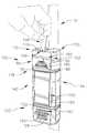
- FIG. 1is a front perspective view of an exemplary preferred blade disposal apparatus according to the present invention, showing the blade disposal apparatus secured to a vertical pole and a user inserting a blade into the blade disposal apparatus through a slot at a top portion of the blade disposal apparatus;
- FIG. 2is a front perspective view of an exemplary preferred blade disposal apparatus and holder unit according to the present invention
- FIG. 3is a back perspective view of the blade disposal apparatus and holder unit of FIG. 2;
- FIG. 4is a top view of the blade disposal apparatus and holder unit of FIG. 2;
- FIG. 5is a cross-sectional view of the blade disposal apparatus and holder unit along line 5 — 5 of FIG. 4;
- FIG. 6is a front perspective view of the blade disposal apparatus of FIG. 1, showing only the blade disposal unit;
- FIG. 7is a front view of the blade disposal unit of FIG. 6;
- FIG. 8is a side view of the blade disposal unit of FIG. 6;
- FIG. 9is a top view of the blade disposal unit of FIG. 6;
- FIG. 10is a cross-sectional view along line 10 — 10 of the blade disposal unit of FIG. 7;
- FIG. 11is an enlarged view of the blade disposal unit within the arc 11 — 11 of FIG. 10;
- FIG. 12is a front perspective view of the exemplary preferred holder unit shown in FIGS. 2-5;
- FIG. 13is a rear perspective view of the holder unit of FIG. 12;
- FIG. 14is a front view of the holder unit of FIG. 12;
- FIG. 15is a side view of the holder unit of FIG. 12.
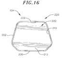
- FIG. 16is a top view of the holder unit of FIG. 12;
- FIG. 17is a front view of a flat blank layout for an alternative exemplary preferred holder unit
- FIG. 18is a front view of the alternative exemplary preferred holder unit of FIG. 17;
- FIG. 19is a side view of the alternative exemplary preferred holder unit of FIG. 17;
- FIG. 20is a bottom view of the alternative exemplary preferred holder unit of FIG. 17.
- FIG. 21is a front perspective view of an alternative exemplary preferred blade disposal unit according to the present invention.
- an exemplary preferred blade disposal apparatus 100includes a blade disposal unit 102 and a holder unit 104 .
- the blade disposal unit or housing 102includes a slot 106 cut-out area sized to receive a razor blade 108 .
- the slot 106is preferably positioned at a top portion 110 of the blade disposal unit 102 as shown.
- An exemplary preferred blade disposal unit 102is sufficiently thick to be rigid, e.g., 0.05 inches nominal wall thickness, and formed from a thermoplastic resin, such as polypropylene, employing a conventional blow molding process resulting in a blow hole 112 .
- the blade disposal unit 102is a “closed” container except for the slot 106 and the blow hole 112 (which is preferably too small for a razor blade to pass through). If desired, the blow hole 112 can be sealed so that the blade disposal unit 102 is entirely closed except for the slot 106 .
- an exemplary preferred blade disposal unit 102is formed with a vertical channel 114 along a back side 116 of the blade disposal unit 102 and at least one groove across the blade disposal unit 102 .
- An exemplary preferred vertical channel 114is formed as shown to accommodate poles with different diameters, as well as poles which are not cylindrical in shape.
- the at least one groovepreferably comprises grooves 118 and 120 which intersect the vertical channel 114 .
- Exemplary preferred grooves 118 and 120each extend continuously around the blade disposal unit 102 from a first side 122 of the vertical channel 114 to a second side 124 of the vertical channel 114 as shown.
- the grooves 118 and 120are positioned symmetrically along the length of the blade disposal unit 102 .
- the illustrated grooves 118 and 120are equidistant from a top surface 126 of the blade disposal unit 102 and a bottom surface 128 of the blade disposal unit 102 , respectively.
- the exemplary preferred grooves 118 and 120are horizontal, i.e., perpendicular to the vertical channel 114 , it should be understood that the present invention is not limited to such an arrangement.
- the at least one groovecan also comprise a single groove or three or more grooves.
- an exemplary preferred blade disposal apparatus 100also includes a plurality of ties for securing the blade disposal unit 102 to a pole 134 as shown.
- the plurality of tiescomprise, for example, plastic ties 130 and 132 which are sized to fit within the grooves 118 and 120 , respectively. Since the typical tie member is not as wide as the typical pole to which the blade disposal unit 102 is secured, the grooves 118 and 120 are preferably, but not necessarily, narrower in width than the vertical channel 114 .
- the exemplary preferred blade disposal unit 102includes a front side 140 , a left side 142 , a right side 144 and curved corner portions 146 , 148 , 150 and 152 adjoined as shown.
- the distance across the blade disposal unit 102between the left side 142 and the right side 144 , decreases moving from the front to the back of the blade disposal unit 102 .
- the top surface 126 and the bottom surface 128are also joined to the back side 116 , the front side 140 , the left side 142 and the right side 144 by a plurality of curved corner portions as shown.
- the exemplary preferred blade disposal unit 102is free of sharp edges or corners other than the slot 106 and the blow hole 112 , if present.
- the holder unit 104is used when the blade disposal unit 102 is to be secured to an object, such as a wall or a board with a flat or substantially flat surface.
- the ergonomic shape of the blade disposal unit 102facilitates secure and comfortable gripping of the blade disposal unit 102 , e.g., for putting the blade disposal unit 102 into or withdrawing it from the holder unit 104 . More specifically, an inside edge of the thumb of a person's gripping hand is placed into the groove 118 on the front side 140 of the blade disposal unit 102 . The tips of the other fingers of that same hand are placed into the vertical channel 114 with the palm of the hand facing either the left side 142 or the right side 144 of the blade disposal unit 102 . So held, the shape of the blade disposal unit 102 and its groove 118 and vertical channel 114 allow the blade disposal unit 102 to be securely gripped even if the blade disposal unit 102 is slippery or wet.
- the exemplary preferred blade disposal unit 102includes at least one external surface formed with visible indicia.
- the at least one external surfacecomprises, for example, a first surface 180 and a second surface 182 which are both positioned on the front side 140 of the blade disposal unit 102 .
- the first surface 180is preferably positioned adjacent the slot 106 .
- the second surface 182is preferably positioned between the groove 120 and the bottom surface 128 .
- the visible indiciainclude text and/or symbols pertaining to the blade disposal apparatus 100 or its contents.
- Exemplary preferred visible indiciaare formed in the blade disposal unit 102 or secured to it in a manner which prevents the visible indicia from being readily removed, obliterated or tampered with.
- Exemplary preferred visible indiciacomprise raised and/or sunken portions of the surfaces 180 and 182 .
- an exemplary preferred first surface 180is formed with raised portions 184 , 186 and 188 .
- An exemplary preferred raised portion 184is triangle-shaped with a top corner of the triangle pointing toward the slot 106 .
- An exemplary preferred raised portion 186forms a trapezoid-shaped border which extends the triangle base of the raised portion 184 .
- An exemplary preferred raised portion 188forms the word “BLADES” and is positioned inside the raised portion 186 as shown.
- the visible indicia(the raised portions 184 , 186 and 188 ) formed on the first surface 180 provide instructions for using the blade disposal apparatus 100 .
- An exemplary preferred second surface 182includes a raised portion 190 which forms, for example, the words “CAUTION CONTAINS SHARP BLADES”.
- the visible indicia (the raised portion 190 ) formed on the second surface 182provide safety information pertaining to the blade disposal apparatus 100 .
- the visible indicia formed on the surfaces 180 and 182are not limited to the specific instructions and safety information described above.
- the surfaces 180 and 182can be positioned differently on the front side 140 or on a portion of the blade disposal unit 102 other than the front side 140 .
- the blade disposal unit 102also includes a label surface 192 suitable for supporting a label 194 which is adhered to the label surface 192 in a conventional fashion.
- the label surface 192is preferably positioned on the front side 140 of the blade disposal unit 102 between the grooves 118 and 120 .
- an exemplary preferred label surface 192is slightly recessed for receiving the label 194 .
- An exemplary preferred label 194includes additional instructions and safety information or other visible indicia such as business logos, advertisements, etc.
- an exemplary preferred holder unit 104includes a main compartment 200 sized to receive the blade disposal unit 102 .
- the holder unit 104is a single piece formed from a thermoplastic resin, such as polypropylene, and has a nominal wall thickness of 0.125 inches.
- a holder unit 104which is assembled from more than one piece, formed from different materials and/or dimensioned differently.
- the exemplary preferred holder unit 104is formed such that the visible indicia are exposed when the blade disposal unit 102 is inserted into the holder unit 104 . More specifically, the exemplary preferred holder unit 104 includes a top edge 202 which is positioned below the first surface 180 and an opening 204 through which the second surface 182 is visible when the blade disposal unit 102 is inserted into the holder unit 104 . Preferably, the top edge 202 of the holder unit 104 includes a recessed portion 206 formed such that the label surface 192 is also visible when the blade disposal unit 102 is inserted into the holder unit 104 .
- An exemplary preferred main compartment 200includes an inner wall 210 and a bottom wall 212 .
- the exemplary preferred inner wall 210is formed to complement the shape of the blade disposal unit 102 and, more specifically, the shape of the back side 116 , the front side 140 , the left side 142 , the right side 144 and the curved corner portions 146 , 148 , 150 and 152 .
- the bottom wall 212contacts the bottom surface 128 of the blade disposal unit 102 .
- An exemplary preferred holder unit 104includes a rear portion 220 with a reinforced inner wall portion 222 .
- An exemplary preferred rear portion 220is flat or substantially flat for mounting the holder unit 104 to an object such as a wall or board in or near the work area.
- the exemplary preferred holder unit 104includes a mounting mechanism such as apertures 224 and 226 which are positioned as shown along the reinforced inner wall portion 222 .
- Conventional flat head screws or the likeare placed through the apertures 224 and 226 and screwed into the object to which the holder unit 104 is to be secured. Securing mechanisms other than the apertures 224 and 226 can also be employed.
- the exemplary preferred holder unit 104also includes a blade compartment 230 sized to receive a box 232 of new razor blades.
- An exemplary preferred blade compartment 230includes a tilted bottom surface 234 which supports the box 232 of razor blades. More specifically, the surface 234 is tilted relative to the rear portion 220 such that the box 232 tends to slide toward the rear portion 220 when the holder unit 104 is in an upright position. The tilted bottom surface 234 lessens the changes that the box 232 of blades will fall out of the blade compartment 230 .
- an alternative exemplary preferred holder unit 240is shown.
- the holder unit 240is formed from a flat blank layout 242 as shown in FIG. 17 .
- An exemplary preferred blank 242comprises a 0.060 inch thick piece of aluminum formed with a back portion 244 and a bottom portion 246 (shown separated by a dashed line 248 ).
- the illustrated back portion 244includes four arm portions 250 , 252 , 254 and 256 with apertures 258 , 260 , 262 and 264 , respectively.
- the illustrated bottom portion 246includes edge portions 266 and 268 . Dashed lines 270 and 272 separate the bottom portion 260 from the edge portions 266 and 268 , respectively.
- the holder unit 240 shown in FIGS. 18-20is formed by folding the blank 244 along the dashed lines 248 , 270 and 272 as shown.
- the edge portions 266 and 268are folded to form right angles with the bottom portion 246 which, in turn, is folded to form an angle slightly smaller than 90° with the back portion 244 .
- the arm portions 244 , 246 , 248 and 250are bent such that the back portion 244 complements the shape of the blade disposal unit 102 and, more specifically, the shape of the back side 116 , the left side 142 , the right side 144 and the curved corner portions 148 and 150 .
- the arm portions 244 , 246 , 248 and 250are bent between their outer edges and apertures 258 , 260 , 262 and 264 to form curved portions 274 , 276 , 278 and 280 , respectively.
- the curved portions 274 , 276 , 278 and 280are formed such that their inner sides fit within the grooves 118 and 120 and their outer sides provide grooves suitable for receiving tie members or the like therein to secure the blade disposal unit 102 against the back portion 244 .
- the bottom portion 246is sized and shaped to support a box of new razor blades below the blade disposal unit 102 when the blade disposal unit 102 is secured to the back portion 244 .
- the bottom portion 246is preferably bent or otherwise formed relative to the back portion 244 such that the box of blades will tend to slide toward the back portion 244 when the holder unit 240 is in an upright position.
- the illustrated exemplary holder unit 240also includes a mounting mechanism such as apertures 282 , 284 and 286 which are positioned as shown along the back portion 244 . It should be understood that the holder unit 240 can be formed from other materials and is not necessarily made from a single piece or in the manner described above.
- an alternative exemplary preferred blade disposal unit 302includes a blade holder unit 304 formed as shown on the top surface 126 .
- the blade holder 304is sized and shaped as shown to hold packs of blades 306 therein.
- the blade holder 304is integrally formed with or molded to the blade disposal unit 302 and formed from like materials. To the extent that their like elements are denoted by like numerals, the blade disposal unit 302 and the previously described blade disposal unit 102 are the same.
Landscapes
- Engineering & Computer Science (AREA)
- Mechanical Engineering (AREA)
- Packaging Of Annular Or Rod-Shaped Articles, Wearing Apparel, Cassettes, Or The Like (AREA)
Abstract
Description
Claims (7)
Priority Applications (1)
| Application Number | Priority Date | Filing Date | Title |
|---|---|---|---|
| US09/493,316US6286675B1 (en) | 2000-01-28 | 2000-01-28 | Blade disposal apparatus and holder unit |
Applications Claiming Priority (1)
| Application Number | Priority Date | Filing Date | Title |
|---|---|---|---|
| US09/493,316US6286675B1 (en) | 2000-01-28 | 2000-01-28 | Blade disposal apparatus and holder unit |
Publications (1)
| Publication Number | Publication Date |
|---|---|
| US6286675B1true US6286675B1 (en) | 2001-09-11 |
Family
ID=23959724
Family Applications (1)
| Application Number | Title | Priority Date | Filing Date |
|---|---|---|---|
| US09/493,316Expired - LifetimeUS6286675B1 (en) | 2000-01-28 | 2000-01-28 | Blade disposal apparatus and holder unit |
Country Status (1)
| Country | Link |
|---|---|
| US (1) | US6286675B1 (en) |
Cited By (15)
| Publication number | Priority date | Publication date | Assignee | Title |
|---|---|---|---|---|
| US20040251801A1 (en)* | 2003-06-10 | 2004-12-16 | Schoick Richard David Van | Storage assembly and method using that storage assembly |
| US20050035126A1 (en)* | 2003-06-25 | 2005-02-17 | Ron Serio | Mountable container system |
| USD527234S1 (en) | 2005-08-23 | 2006-08-29 | Irwin Industrial Tool Company | Utility knife blade |
| WO2007019622A1 (en)* | 2005-08-18 | 2007-02-22 | Robert Jonathan Bernardis | Refuse receptacle for sachets |
| US20070101576A1 (en)* | 2005-11-10 | 2007-05-10 | Irwin Industrial Tool Company | Blunt tip utility blade |
| US20100147869A1 (en)* | 2008-12-12 | 2010-06-17 | The Stanley Works | Blade dispenser |
| US20120006705A1 (en)* | 2010-05-03 | 2012-01-12 | Satnam Singh | Knife blade container |
| US20170328567A1 (en)* | 2016-05-11 | 2017-11-16 | United Technologies Corporation | Multivariable fuel control and estimator (mfce) for preventing combustor blowout |
| USD833007S1 (en) | 2016-10-20 | 2018-11-06 | Luis Tirado | Blade disposal box |
| US20180339809A1 (en)* | 2017-05-26 | 2018-11-29 | Eagle Holdings LLC | Portable article holder |
| US10244842B2 (en) | 2016-04-25 | 2019-04-02 | Luis Tirado | Blade disposal container |
| US10321968B2 (en) | 2015-10-23 | 2019-06-18 | Medline Industries, Inc. | Sharps container |
| US20210085053A1 (en)* | 2019-09-19 | 2021-03-25 | Carl Pickett | Razor Drop |
| USD1023296S1 (en)* | 2013-04-23 | 2024-04-16 | Kpr U.S., Llc | Cassette |
| US20250145370A1 (en)* | 2023-11-06 | 2025-05-08 | Industro International Co., Ltd. | Blade container operable to sever a blade |
Citations (23)
| Publication number | Priority date | Publication date | Assignee | Title |
|---|---|---|---|---|
| US1476401A (en) | 1923-02-20 | 1923-12-04 | John J Hechmer | Method of and container for storing used safety-razor blades |
| US1634777A (en)* | 1925-01-27 | 1927-07-05 | Samuel B Girdler | Receptacle |
| US1770289A (en) | 1925-09-17 | 1930-07-08 | American Stamping Co | Combination holder for razor blades and paper |
| US1910374A (en) | 1931-01-30 | 1933-05-23 | J B Williams Company | Receptacle for safety razor blades |
| US2006696A (en)* | 1933-11-21 | 1935-07-02 | Us Printing & Lithograph Co | Merchandising receptacle |
| US2065607A (en) | 1935-10-23 | 1936-12-29 | Montgomery Ward & Co Inc | Combination razor blade container and dispenser |
| US2071978A (en)* | 1936-01-18 | 1937-02-23 | Gillette Safety Razor Co | Package and receptacle |
| US2182615A (en)* | 1938-02-28 | 1939-12-05 | Saks And Company | Container |
| US2231726A (en)* | 1939-08-17 | 1941-02-11 | Nevins Church Press | Folding box |
| US2441777A (en) | 1945-04-20 | 1948-05-18 | Gillette Safety Razor Co | Receiver for used blades |
| US2453238A (en) | 1945-01-08 | 1948-11-09 | Gillette Safety Razor Co | Blade container |
| US3255913A (en) | 1964-08-31 | 1966-06-14 | Hoover Co | Liquid container with integral mounting means |
| US4711367A (en)* | 1985-11-01 | 1987-12-08 | Albertson Robert V | Trash container |
| US4715498A (en) | 1986-11-24 | 1987-12-29 | Sage Products, Inc. | Sharps disposal system |
| US4759441A (en) | 1986-10-14 | 1988-07-26 | Leurck William J | Combination tool for use in hanging wallpaper |
| US4809850A (en) | 1988-03-28 | 1989-03-07 | Custom Medical Plastics, Inc. | Self-closing sharps container with hand protection |
| USD307841S (en) | 1988-04-15 | 1990-05-15 | Sage Products, Inc. | Combined needle disposal container and glove dispenser |
| US5058764A (en) | 1991-01-04 | 1991-10-22 | Devon Industries, Inc. | Mounting bracket having a hidden lock for a sharps collection system |
| USD334449S (en) | 1991-01-04 | 1993-03-30 | Devon Industries, Inc. | Sharps collection container holder |
| US5240107A (en)* | 1992-12-02 | 1993-08-31 | James Casale | Razor holder with shave counter |
| US5887774A (en)* | 1984-01-20 | 1999-03-30 | Bethune; Peter R. | Exercise fluid bottle |
| US5894925A (en) | 1996-01-24 | 1999-04-20 | Kimberly-Clark Worldwide, Inc. | Medical sharps blade removal and containment structure |
| US5901874A (en)* | 1996-05-07 | 1999-05-11 | Breakthrough Marketing, Inc. | Handicapped accessible dumpster |
- 2000
- 2000-01-28USUS09/493,316patent/US6286675B1/ennot_activeExpired - Lifetime
Patent Citations (23)
| Publication number | Priority date | Publication date | Assignee | Title |
|---|---|---|---|---|
| US1476401A (en) | 1923-02-20 | 1923-12-04 | John J Hechmer | Method of and container for storing used safety-razor blades |
| US1634777A (en)* | 1925-01-27 | 1927-07-05 | Samuel B Girdler | Receptacle |
| US1770289A (en) | 1925-09-17 | 1930-07-08 | American Stamping Co | Combination holder for razor blades and paper |
| US1910374A (en) | 1931-01-30 | 1933-05-23 | J B Williams Company | Receptacle for safety razor blades |
| US2006696A (en)* | 1933-11-21 | 1935-07-02 | Us Printing & Lithograph Co | Merchandising receptacle |
| US2065607A (en) | 1935-10-23 | 1936-12-29 | Montgomery Ward & Co Inc | Combination razor blade container and dispenser |
| US2071978A (en)* | 1936-01-18 | 1937-02-23 | Gillette Safety Razor Co | Package and receptacle |
| US2182615A (en)* | 1938-02-28 | 1939-12-05 | Saks And Company | Container |
| US2231726A (en)* | 1939-08-17 | 1941-02-11 | Nevins Church Press | Folding box |
| US2453238A (en) | 1945-01-08 | 1948-11-09 | Gillette Safety Razor Co | Blade container |
| US2441777A (en) | 1945-04-20 | 1948-05-18 | Gillette Safety Razor Co | Receiver for used blades |
| US3255913A (en) | 1964-08-31 | 1966-06-14 | Hoover Co | Liquid container with integral mounting means |
| US5887774A (en)* | 1984-01-20 | 1999-03-30 | Bethune; Peter R. | Exercise fluid bottle |
| US4711367A (en)* | 1985-11-01 | 1987-12-08 | Albertson Robert V | Trash container |
| US4759441A (en) | 1986-10-14 | 1988-07-26 | Leurck William J | Combination tool for use in hanging wallpaper |
| US4715498A (en) | 1986-11-24 | 1987-12-29 | Sage Products, Inc. | Sharps disposal system |
| US4809850A (en) | 1988-03-28 | 1989-03-07 | Custom Medical Plastics, Inc. | Self-closing sharps container with hand protection |
| USD307841S (en) | 1988-04-15 | 1990-05-15 | Sage Products, Inc. | Combined needle disposal container and glove dispenser |
| USD334449S (en) | 1991-01-04 | 1993-03-30 | Devon Industries, Inc. | Sharps collection container holder |
| US5058764A (en) | 1991-01-04 | 1991-10-22 | Devon Industries, Inc. | Mounting bracket having a hidden lock for a sharps collection system |
| US5240107A (en)* | 1992-12-02 | 1993-08-31 | James Casale | Razor holder with shave counter |
| US5894925A (en) | 1996-01-24 | 1999-04-20 | Kimberly-Clark Worldwide, Inc. | Medical sharps blade removal and containment structure |
| US5901874A (en)* | 1996-05-07 | 1999-05-11 | Breakthrough Marketing, Inc. | Handicapped accessible dumpster |
Non-Patent Citations (2)
| Title |
|---|
| Cut Saver Razor Blade Disposal Unit brochure (photocopy of brochure). |
| Cut Saver, Cut Saver Razor Blade Disposal Unit brochure, published in 1999. |
Cited By (18)
| Publication number | Priority date | Publication date | Assignee | Title |
|---|---|---|---|---|
| US20040251801A1 (en)* | 2003-06-10 | 2004-12-16 | Schoick Richard David Van | Storage assembly and method using that storage assembly |
| US20050035126A1 (en)* | 2003-06-25 | 2005-02-17 | Ron Serio | Mountable container system |
| WO2007019622A1 (en)* | 2005-08-18 | 2007-02-22 | Robert Jonathan Bernardis | Refuse receptacle for sachets |
| USD527234S1 (en) | 2005-08-23 | 2006-08-29 | Irwin Industrial Tool Company | Utility knife blade |
| US20070101576A1 (en)* | 2005-11-10 | 2007-05-10 | Irwin Industrial Tool Company | Blunt tip utility blade |
| US20100147869A1 (en)* | 2008-12-12 | 2010-06-17 | The Stanley Works | Blade dispenser |
| US20120006705A1 (en)* | 2010-05-03 | 2012-01-12 | Satnam Singh | Knife blade container |
| USD1023296S1 (en)* | 2013-04-23 | 2024-04-16 | Kpr U.S., Llc | Cassette |
| US11559369B2 (en) | 2015-10-23 | 2023-01-24 | Medline Industries, Lp | Sharps container |
| US12082951B2 (en) | 2015-10-23 | 2024-09-10 | Medine Industries, LP | Sharps container |
| US10321968B2 (en) | 2015-10-23 | 2019-06-18 | Medline Industries, Inc. | Sharps container |
| US10244842B2 (en) | 2016-04-25 | 2019-04-02 | Luis Tirado | Blade disposal container |
| US20170328567A1 (en)* | 2016-05-11 | 2017-11-16 | United Technologies Corporation | Multivariable fuel control and estimator (mfce) for preventing combustor blowout |
| USD833007S1 (en) | 2016-10-20 | 2018-11-06 | Luis Tirado | Blade disposal box |
| US20180339809A1 (en)* | 2017-05-26 | 2018-11-29 | Eagle Holdings LLC | Portable article holder |
| US11877640B2 (en)* | 2019-09-19 | 2024-01-23 | Carl Pickett | Razor drop |
| US20210085053A1 (en)* | 2019-09-19 | 2021-03-25 | Carl Pickett | Razor Drop |
| US20250145370A1 (en)* | 2023-11-06 | 2025-05-08 | Industro International Co., Ltd. | Blade container operable to sever a blade |
Similar Documents
| Publication | Publication Date | Title |
|---|---|---|
| US6286675B1 (en) | Blade disposal apparatus and holder unit | |
| EP1901974B1 (en) | Container for storing a shaving implement | |
| US5561905A (en) | Letter opener | |
| US5009003A (en) | Razor | |
| US20030085236A1 (en) | Blade dispenser assembly | |
| CA1223570A (en) | Child proof container | |
| WO2016182951A1 (en) | Hearing aid battery packaging | |
| JP2021127175A (en) | Pet bottle cap and pet bottle | |
| EP3073872B1 (en) | Plate | |
| EP0854020B1 (en) | Protective cover for a razor head | |
| US6557258B1 (en) | Dual blade cutter | |
| US6938765B2 (en) | Razor blade holder | |
| US6942115B2 (en) | Protective packaging unit | |
| US20050274026A1 (en) | Vinyl pack opener | |
| JP3983791B1 (en) | Blister container | |
| US6739488B1 (en) | Tablet cutter | |
| GB2237733A (en) | Hand grips | |
| JPH07222619A (en) | Distribution container of razor-blade device for safety razor | |
| NL8902650A (en) | HOLDER WITH A LID. | |
| JP3293288B2 (en) | Storage container | |
| JP5728286B2 (en) | Packaging box with handle | |
| JP2000279659A (en) | Plastic bag cutter | |
| US6901663B2 (en) | Hand-held tool for piercing and scraping | |
| EP3676891A1 (en) | Hearing aid battery packaging | |
| JP2542488Y2 (en) | Central opening plastic blow molded bottle |
Legal Events
| Date | Code | Title | Description |
|---|---|---|---|
| AS | Assignment | Owner name:PACIFIC HANDY CUTTER, INC., CALIFORNIA Free format text:ASSIGNMENT OF ASSIGNORS INTEREST;ASSIGNOR:SCHMIDT, G. GERRY;REEL/FRAME:010533/0368 Effective date:20000125 | |
| STCF | Information on status: patent grant | Free format text:PATENTED CASE | |
| AS | Assignment | Owner name:UNION BANK OF CALIFORNIA, N.A., CALIFORNIA Free format text:SECURITY AGREEMENT;ASSIGNOR:PACIFIC HANDY CUTTER, INC.;REEL/FRAME:014301/0614 Effective date:20030731 | |
| FPAY | Fee payment | Year of fee payment:4 | |
| AS | Assignment | Owner name:PACIFIC HANDY CUTTER, INC., CALIFORNIA Free format text:FULL RELEASE OF PATENT COLLATERAL;ASSIGNOR:UNION BANK OF CALIFORNIA, N.A.;REEL/FRAME:018767/0763 Effective date:20061229 | |
| AS | Assignment | Owner name:AMERICAN CAPITAL FINANCIAL SERVICES, INC.,MARYLAND Free format text:SECURITY AGREEMENT;ASSIGNOR:PACIFIC HANDY CUTTER, INC.;REEL/FRAME:018861/0437 Effective date:20061227 Owner name:AMERICAN CAPITAL FINANCIAL SERVICES, INC.,MARYLAND Free format text:SECURITY AGREEMENT;ASSIGNOR:PACIFIC HANDY CUTTER, INC.;REEL/FRAME:018861/0459 Effective date:20061227 Owner name:AMERICAN CAPITAL FINANCIAL SERVICES, INC., MARYLAN Free format text:SECURITY AGREEMENT;ASSIGNOR:PACIFIC HANDY CUTTER, INC.;REEL/FRAME:018861/0437 Effective date:20061227 Owner name:AMERICAN CAPITAL FINANCIAL SERVICES, INC., MARYLAN Free format text:SECURITY AGREEMENT;ASSIGNOR:PACIFIC HANDY CUTTER, INC.;REEL/FRAME:018861/0459 Effective date:20061227 | |
| FPAY | Fee payment | Year of fee payment:8 | |
| REMI | Maintenance fee reminder mailed | ||
| FPAY | Fee payment | Year of fee payment:12 | |
| SULP | Surcharge for late payment | Year of fee payment:11 | |
| AS | Assignment | Owner name:ABACUS FINANCE GROUP, LLC, NEW YORK Free format text:SECURITY INTEREST;ASSIGNOR:PACIFIC HANDY CUTTER, INC.;REEL/FRAME:039423/0528 Effective date:20160810 | |
| AS | Assignment | Owner name:PACIFIC HANDY CUTTER, INC., CALIFORNIA Free format text:RELEASE BY SECURED PARTY;ASSIGNOR:ABACUS FINANCE GROUP, LLC, AS ADMINISTRATIVE AGENT;REEL/FRAME:044769/0453 Effective date:20180130 | |
| AS | Assignment | Owner name:MADISON CAPITAL FUNDING LLC, ILLINOIS Free format text:SECURITY INTEREST;ASSIGNOR:PACIFIC HANDY CUTTER, INC.;REEL/FRAME:045201/0097 Effective date:20180130 | |
| AS | Assignment | Owner name:LEVINE LEICHTMAN CAPITAL PARTNERS SBIC FUND, L.P., Free format text:SECURITY INTEREST;ASSIGNOR:PACIFIC HANDY CUTTER, INC.;REEL/FRAME:045215/0766 Effective date:20180130 | |
| AS | Assignment | Owner name:PACIFIC HANDY CUTTER, INC., CALIFORNIA Free format text:RELEASE BY SECURED PARTY;ASSIGNOR:ACAS, LLC;REEL/FRAME:049142/0702 Effective date:20181218 Owner name:PACIFIC HANDY CUTTER, INC., CALIFORNIA Free format text:RELEASE BY SECURED PARTY;ASSIGNOR:ACAS, LLC;REEL/FRAME:047964/0546 Effective date:20181218 | |
| AS | Assignment | Owner name:PACIFIC HANDY CUTTER, INC., CALIFORNIA Free format text:RELEASE BY SECURED PARTY;ASSIGNOR:LEVINE LEICHTMAN SMALL BUSINESS FUND, L.P.;REEL/FRAME:054791/0664 Effective date:20201216 Owner name:PACIFIC HANDY CUTTER, INC., CALIFORNIA Free format text:RELEASE BY SECURED PARTY;ASSIGNOR:MADISON CAPITAL FUNDING LLC;REEL/FRAME:054793/0001 Effective date:20201216 |