US6285903B1 - Intracorporeal device with radiopaque marker - Google Patents
Intracorporeal device with radiopaque markerDownload PDFInfo
- Publication number
- US6285903B1 US6285903B1US09/107,843US10784398AUS6285903B1US 6285903 B1US6285903 B1US 6285903B1US 10784398 AUS10784398 AUS 10784398AUS 6285903 B1US6285903 B1US 6285903B1
- Authority
- US
- United States
- Prior art keywords
- delivery catheter
- shaft
- radiopaque marker
- section
- marker member
- Prior art date
- Legal status (The legal status is an assumption and is not a legal conclusion. Google has not performed a legal analysis and makes no representation as to the accuracy of the status listed.)
- Expired - Fee Related
Links
- 239000003550markerSubstances0.000titleclaimsabstractdescription113
- 210000002216heartAnatomy0.000claimsabstractdescription25
- 230000001225therapeutic effectEffects0.000claimsabstractdescription14
- 210000005240left ventricleAnatomy0.000claimsdescription24
- 239000000463materialSubstances0.000claimsdescription24
- 238000000034methodMethods0.000claimsdescription22
- 238000002679ablationMethods0.000claimsdescription13
- 229910052751metalInorganic materials0.000claimsdescription7
- 239000002184metalSubstances0.000claimsdescription7
- 238000004891communicationMethods0.000claimsdescription6
- 239000012530fluidSubstances0.000claimsdescription6
- 238000002560therapeutic procedureMethods0.000claimsdescription4
- 238000002405diagnostic procedureMethods0.000claimsdescription3
- 238000003384imaging methodMethods0.000abstractdescription3
- 230000000250revascularizationEffects0.000description12
- 210000001174endocardiumAnatomy0.000description7
- 210000005242cardiac chamberAnatomy0.000description6
- 238000012800visualizationMethods0.000description6
- 210000001519tissueAnatomy0.000description5
- 238000010276constructionMethods0.000description4
- BASFCYQUMIYNBI-UHFFFAOYSA-NplatinumChemical compound[Pt]BASFCYQUMIYNBI-UHFFFAOYSA-N0.000description4
- GUVRBAGPIYLISA-UHFFFAOYSA-Ntantalum atomChemical compound[Ta]GUVRBAGPIYLISA-UHFFFAOYSA-N0.000description4
- 239000003795chemical substances by applicationSubstances0.000description3
- 238000002594fluoroscopyMethods0.000description3
- PCHJSUWPFVWCPO-UHFFFAOYSA-NgoldChemical compound[Au]PCHJSUWPFVWCPO-UHFFFAOYSA-N0.000description3
- 230000013011matingEffects0.000description3
- 230000002107myocardial effectEffects0.000description3
- 239000002861polymer materialSubstances0.000description3
- 208000027418Wounds and injuryDiseases0.000description2
- 239000000853adhesiveSubstances0.000description2
- 230000001070adhesive effectEffects0.000description2
- 210000000709aortaAnatomy0.000description2
- 210000001367arteryAnatomy0.000description2
- 230000015572biosynthetic processEffects0.000description2
- 229910052797bismuthInorganic materials0.000description2
- JCXGWMGPZLAOME-UHFFFAOYSA-Nbismuth atomChemical compound[Bi]JCXGWMGPZLAOME-UHFFFAOYSA-N0.000description2
- 230000006378damageEffects0.000description2
- 229910052737goldInorganic materials0.000description2
- 239000010931goldSubstances0.000description2
- 208000014674injuryDiseases0.000description2
- 210000004165myocardiumAnatomy0.000description2
- 230000002093peripheral effectEffects0.000description2
- 229910052697platinumInorganic materials0.000description2
- 229920000642polymerPolymers0.000description2
- 239000000843powderSubstances0.000description2
- 229910052715tantalumInorganic materials0.000description2
- 229920001651CyanoacrylatePolymers0.000description1
- 239000004593EpoxySubstances0.000description1
- JOYRKODLDBILNP-UHFFFAOYSA-NEthyl urethaneChemical compoundCCOC(N)=OJOYRKODLDBILNP-UHFFFAOYSA-N0.000description1
- 241000629493ExtremusSpecies0.000description1
- 102100024785Fibroblast growth factor 2Human genes0.000description1
- 108090000379Fibroblast growth factor 2Proteins0.000description1
- MWCLLHOVUTZFKS-UHFFFAOYSA-NMethyl cyanoacrylateChemical compoundCOC(=O)C(=C)C#NMWCLLHOVUTZFKS-UHFFFAOYSA-N0.000description1
- GRYLNZFGIOXLOG-UHFFFAOYSA-NNitric acidChemical compoundO[N+]([O-])=OGRYLNZFGIOXLOG-UHFFFAOYSA-N0.000description1
- 239000004698PolyethyleneSubstances0.000description1
- 102000005789Vascular Endothelial Growth FactorsHuman genes0.000description1
- 108010019530Vascular Endothelial Growth FactorsProteins0.000description1
- KMKOQNVUUNIMNW-HZJNKCPISA-N[(8r,9s,10r,13s,14s,17s)-10,13-dimethyl-3-oxo-1,2,6,7,8,9,11,12,14,15,16,17-dodecahydrocyclopenta[a]phenanthren-17-yl] heptanoate;[(8r,9s,10r,13s,14s)-17-ethynyl-13-methyl-3-oxo-1,2,6,7,8,9,10,11,12,14,15,16-dodecahydrocyclopenta[a]phenanthren-17-yl] acetChemical compoundC1CC2=CC(=O)CC[C@@H]2[C@@H]2[C@@H]1[C@@H]1CCC(C#C)(OC(=O)C)[C@@]1(C)CC2.C1CC2=CC(O)=CC=C2C2C1C1CC[C@H](OC(=O)CCCC)[C@@]1(C)CC2.C([C@]1(C2CC[C@@H]1O)C)CC(C1=CC=3)C2CCC1=CC=3OC(=O)C1=CC=CC=C1.C1CC2=CC(=O)CC[C@]2(C)[C@@H]2[C@@H]1[C@@H]1CC[C@H](OC(=O)CCCCCC)[C@@]1(C)CC2KMKOQNVUUNIMNW-HZJNKCPISA-N0.000description1
- 210000003484anatomyAnatomy0.000description1
- 230000002491angiogenic effectEffects0.000description1
- 210000001765aortic valveAnatomy0.000description1
- 229910052788bariumInorganic materials0.000description1
- DSAJWYNOEDNPEQ-UHFFFAOYSA-Nbarium atomChemical compound[Ba]DSAJWYNOEDNPEQ-UHFFFAOYSA-N0.000description1
- 238000010009beatingMethods0.000description1
- 239000000560biocompatible materialSubstances0.000description1
- 239000003814drugSubstances0.000description1
- 210000001105femoral arteryAnatomy0.000description1
- 230000004927fusionEffects0.000description1
- 238000007499fusion processingMethods0.000description1
- 238000002682general surgeryMethods0.000description1
- 210000005003heart tissueAnatomy0.000description1
- 239000007924injectionSubstances0.000description1
- 238000002347injectionMethods0.000description1
- 230000000302ischemic effectEffects0.000description1
- 238000004519manufacturing processMethods0.000description1
- 229910017604nitric acidInorganic materials0.000description1
- -1polyethylenePolymers0.000description1
- 229920000573polyethylenePolymers0.000description1
- 150000003180prostaglandinsChemical class0.000description1
- 230000003014reinforcing effectEffects0.000description1
- 229940124597therapeutic agentDrugs0.000description1
- 210000000115thoracic cavityAnatomy0.000description1
- 210000000779thoracic wallAnatomy0.000description1
- 208000037816tissue injuryDiseases0.000description1
- 230000007704transitionEffects0.000description1
- 238000002604ultrasonographyMethods0.000description1
- 230000002861ventricularEffects0.000description1
- 239000013603viral vectorSubstances0.000description1
- XLYOFNOQVPJJNP-UHFFFAOYSA-NwaterSubstancesOXLYOFNOQVPJJNP-UHFFFAOYSA-N0.000description1
Images


Classifications
- A—HUMAN NECESSITIES
- A61—MEDICAL OR VETERINARY SCIENCE; HYGIENE
- A61M—DEVICES FOR INTRODUCING MEDIA INTO, OR ONTO, THE BODY; DEVICES FOR TRANSDUCING BODY MEDIA OR FOR TAKING MEDIA FROM THE BODY; DEVICES FOR PRODUCING OR ENDING SLEEP OR STUPOR
- A61M25/00—Catheters; Hollow probes
- A61M25/01—Introducing, guiding, advancing, emplacing or holding catheters
- A61M25/0105—Steering means as part of the catheter or advancing means; Markers for positioning
- A61M25/0108—Steering means as part of the catheter or advancing means; Markers for positioning using radio-opaque or ultrasound markers
- A—HUMAN NECESSITIES
- A61—MEDICAL OR VETERINARY SCIENCE; HYGIENE
- A61B—DIAGNOSIS; SURGERY; IDENTIFICATION
- A61B6/00—Apparatus or devices for radiation diagnosis; Apparatus or devices for radiation diagnosis combined with radiation therapy equipment
- A61B6/12—Arrangements for detecting or locating foreign bodies
- A—HUMAN NECESSITIES
- A61—MEDICAL OR VETERINARY SCIENCE; HYGIENE
- A61B—DIAGNOSIS; SURGERY; IDENTIFICATION
- A61B90/00—Instruments, implements or accessories specially adapted for surgery or diagnosis and not covered by any of the groups A61B1/00 - A61B50/00, e.g. for luxation treatment or for protecting wound edges
- A61B90/39—Markers, e.g. radio-opaque or breast lesions markers
Definitions
- This inventiongenerally relates to devices and methods for visualization of elongated devices for therapeutic or diagnostic procedures in a patient's body.
- the inventionrelates to the positioning of the distal end of a catheter or catheter system within a patient's body using radiopaque marker members in conjunction with fluoroscopic or other suitable visualization systems.
- One specific application of the inventionincludes visualization of the distal end of an elongated delivery catheter while performing myocardial revascularization, tissue ablation, delivery of an angiogenic agent, or other desired therapy.
- Myocardial revascularizationtypically involves tissue ablation, tissue injury, or formation of one or more channels in a patient's heart wall which defines the heart chamber, particularly the left ventricle.
- the first trials of the revascularization processwere made by Mirhoseini et al. Lasers in General Surgery (Williams & Wilkins; 1989), pp. 216-223. Other early disclosures of this procedure are found in an article by Okada et al. in Kobe J. Med. Sci 32, 151-161, October 1986 and in U.S. Pat. No. 4,658,817 (Hardy). Both of these references describe intraoperative revascularization procedures which require the chest wall to be opened and which include formation of the revascularization channels completely through the heart wall, i.e., the epicardium, myocardium and endocardium.
- What has been neededis an improved system and method for visualizing a delivery catheter or delivery catheter system during a percutaneous procedure.
- a system and method for fluoroscopic visualization of a catheterthat facilitates visualization under two dimensional fluoroscopy without the need to view from more than one plane.
- the present inventionsatisfies these and other needs.
- the present inventionis directed to devices and methods that incorporate a radiopaque marker member into an intracorporeal device having an elongated shaft with a distal and a proximal end.
- the radiopaque marker memberis disposed upon or within the elongated shaft proximal of the distal end thereof and has a first radiopaque section spaced longitudinally or transversely from a second radiopaque section disposed upon or within the elongated shaft.
- Such a configurationallows the operator of the intracorporeal catheter to ascertain the orientation of the catheter by fluoroscopic imaging.
- Another embodiment of the inventionincorporates a radiopaque marker member with an intracorporeal device having an elongate shaft with a proximal and distal end and a curvature.
- the marker memberis disposed upon or within the elongate shaft proximal of the distal end and has a curved shape which conforms generally to the curvature of the shaft.
- the marker memberhas a first longitudinal section that does not completely surround a circumference of the shaft and a second longitudinal section that does completely surround the circumference of the shaft so as to create a fluoroscopic projection which reveals the orientation of the shaft.
- a radiopaque marker memberis used in conjunction with a catheter delivery system for percutaneously delivering an elongated therapeutic or diagnostic device into the interior of a patient's heart chamber.
- the systemprovides access to a wide region of the patient's endocardium defining at least in part the heart chamber.
- the catheter delivery system of one embodiment of the inventiongenerally includes a first delivery catheter which has a relatively straight main shaft section and a shaped distal shaft section having a discharge axis selected so that is generally aligned with or parallel to a longitudinal axis of the patient's left ventricle.
- a second delivery catheteris slidably and rotatably disposed within an inner lumen of the first delivery catheter and provided with a shaped distal section configured to have a discharge axis which is normal or near normal to the patient's endocardial layer which defines in part the left ventricle.
- a radiopaque marker membermay be disposed on or within a distal section of either or both of the delivery catheters.
- the first segment of the distal shaft sectionis at an angle of about 95° to about 160°, preferably about 100° to about 140° with respect to a proximally adjacent second segment of the distal shaft section and the proximally adjacent second segment is at an angle of about 95° to about 160°, preferably about 100° to about 135° with respect to either the proximally adjacent main shaft section or a third segment of the distal shaft section proximally adjacent to the second segment.
- the distal sectionIn those embodiments where there is a third segment of the distal section, it is at an angle of about angle of about 110° to about 170°, preferably about 120° to about 150° with respect to proximally adjacent main shaft section.
- the first and second segmentsshould each be about 0.5 to about 5, preferably about 0.5 to about 4 cm in length, with the total length of the shaped distal section with two segments being about 2 to about 6 cm. If the distal section has a third segment, it should have a length of about 1 to about 5 cm, preferably about 2 to about 4 cm.
- the length of the shaped distal section with three segmentsshould be about 3 to about 8 cm, preferably about 4 to about 7 cm.
- the shaped distal section of the first delivery catheterhas a single angled segment which provides a discharge axis approximating the longitudinal axis or long dimension of the heart chamber.
- the single angled segment of the distal shaft sectionhas a length of about 2 to about 8 cm, preferably about 4 to about 6 cm and is at an angle of about 95° to about 160°, preferably about 100° to about 140° with respect to a proximally adjacent portion of the main shaft section.
- the second delivery catheterpreferably has a relatively straight main shaft section and a distal section which is at an angle of about 80° to about 140°, preferably about 90° to about 120° with respect to the main shaft section thereof.
- the second delivery cathetershould be at least 10 cm longer, preferably about 15 to about 50 cm longer, than the first delivery catheter and is about 100 to about 150 cm, preferably about 110 to about 140 cm in length.
- the shaped distal section of the second delivery cathetershould have a radius of curvature of about 2 to 30 mm, preferably about 4 to about 20 mm between the main shaft section and the exit or discharge axis through the port in the distal end of the shaped distal section.
- the length of the shaped distal sectionis about 0.5 to about 4 cm, preferably about 1 to about 3 cm.
- a presently preferred elongated therapeutic or diagnostic device for use with the catheter delivery systemis a device for revascularization of tissue within the wall of the patient's heart, particularly for ablation of an ischemic region thereof.
- the ablation deviceis adapted to emit ablation energy from its distal end which may be based on laser, radiofrequency, ultrasonic or other high energy emissions.
- the ablation deviceis slidably disposed within the inner lumen of the second delivery catheter and is long enough so that the distal operative end can extend out the port in the distal end of the second delivery catheter and contact the endocardium while the proximal end is operatively connected to a source of ablation energy such as laser, RF, ultrasound and the like.
- the distal extremity of the ablation device which extends out the distal end of the delivery catheterhas sufficient rigidity to be self-supporting within the environment of the heart chamber.
- the first delivery catheter of the catheter delivery systemis introduced into a peripheral artery, such as the femoral artery, and advanced through the patient's arterial system until the distal end of the first catheter is disposed within the patient's left ventricle.
- the position of the first delivery catheteris adjusted by the physician under fluoroscopic observation of the shaft and/or the radiopaque marker member disposed thereon until the distal tip is oriented generally along or parallel to the longitudinal axis of the left ventricle.
- the second delivery catheteris advanced through the previously introduced first delivery catheter which has a distal end appropriately positioned within the left ventricle.
- the second delivery catheteris positioned within the inner lumen of the first delivery catheter under fluoroscopic imaging until the shaped distal section of the second delivery catheter is within the left ventricle normal to the endocardium.
- the orientation of the distal tip of the second delivery catheteris ascertained by the image produced by the radiopaque marker member on or within the distal tip thereof.
- the elongated therapeutic or diagnostic device slidably disposed within the inner lumen of the second delivery catheteris properly oriented with respect to the endocardial surface of the heart chamber.
- the perpendicular orientationhelps to maintain the position of the distal end of the device, particularly a channel forming device, against the heart wall during multiple heart cycles.
- the use of dye injections through a port in the distal end of first and/or the second delivery cathetermay be employed to further facilitate the location of the distal end of these catheters.
- FIG. 1Ashows an elevational view of an intracorporeal device or first delivery catheter.
- FIG. 1Bshows an elevational view of an intracorporeal device or second delivery catheter.
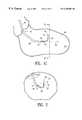
- FIG. 1Cshows an elevational view in partial section of a catheter delivery system which incorporates a radiopaque marker member disposed within a patient's left ventricle.
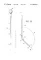
- FIG. 2shows a perspective view of a catheter delivery system which incorporates a radiopaque marker member disposed within a patient's left ventricle.
- FIG. 3shows an elevational view of the distal section of a catheter delivery system which incorporates a radiopaque marker member wherein the distal end of the second delivery catheter is pointing upwards.
- FIG. 4depicts a cross sectional view of the catheter delivery system of FIG. 3 taken at section 4 — 4 .
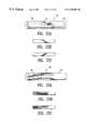
- FIG. 5shows an elevational view of the distal section of a catheter delivery system which incorporates a radiopaque marker member wherein the distal end of the second delivery catheter is pointing out of the page.
- FIG. 6shows an elevational view of the distal section of a catheter delivery system which incorporates a radiopaque marker member wherein the distal end of the second delivery catheter is pointing into the page.
- FIGS. 7A-7Bshow a perspective view of an embodiment of a radiopaque marker member.
- FIGS. 8A-8Bshow a perspective view of an embodiment of a radiopaque marker member.
- FIGS. 9A-9Bshow a perspective view of an embodiment of a radiopaque marker member.
- FIGS. 10A-10Bshow a perspective view of an embodiment of a radiopaque marker member.
- FIGS. 10C-10Ddepict radiographic projections of a catheter system incorporating the embodiment of the radiopaque marker of FIGS. 10A and 10B.
- FIGS. 11A-11Bshow a perspective view of an embodiment of a radiopaque marker member.
- FIGS. 11C-11Ddepict radiographic projections of a catheter system incorporating the embodiment of the radiopaque marker of FIGS. 11A and 11B.
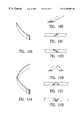
- FIGS. 12A-12Bshow a perspective view of an embodiment of a radiopaque marker member.
- FIGS. 12C-12Ddepict radiographic projections of a catheter system incorporating the embodiment of the radiopaque marker of FIGS. 12A and 12B.
- FIGS. 13A-13Bshow a perspective view of an embodiment of a radiopaque marker member.
- FIGS. 13C-13Ddepict radiographic projections of a catheter system incorporating the embodiment of the radiopaque marker of FIGS. 13A and 13B.
- FIGS. 14A-14Bshow a perspective view of an embodiment of a radiopaque marker member.
- FIGS. 14C-14Ddepict radiographic projections of a catheter system incorporating the embodiment of the radiopaque marker of FIGS. 14A and 14B.
- FIG. 15Ashow a perspective view of an embodiment of a radiopaque marker member.
- FIGS. 15B-15Cdepict radiographic projections of a catheter system incorporating the embodiment of the radiopaque marker of FIG. 15 A.
- FIG. 16Ashow a perspective view of an embodiment of a radiopaque marker member.
- FIGS. 16B-16Cdepict radiographic projections of a catheter system incorporating the embodiment of the radiopaque marker of FIG. 16 A.
- FIGS. 17A-17Bshow a perspective view of an embodiment of a radiopaque marker member.
- FIGS. 17C-17Ddepict radiographic projections of a catheter system incorporating the embodiment of the radiopaque marker of FIGS. 17A and 17B.
- FIGS. 18A-18Bshow a perspective view of an embodiment of a radiopaque marker member.
- FIGS. 18C-18Ddepict radiographic projections of a catheter system incorporating the embodiment of the radiopaque marker of FIGS. 18A and 18B.
- FIGS. 19A-19Bshow a perspective view of an embodiment of a radiopaque marker member.
- FIGS. 19C-19Ddepict radiographic projections of a catheter system incorporating the embodiment of the radiopaque marker of FIGS. 19A and 19B.
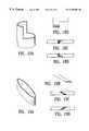
- FIG. 20Ashows an exploded view of a section of an elongate catheter shaft having a radiopaque marker member disposed between two concentric tubular members which comprise a shaft.
- FIG. 20Bshows a perspective view partially cutaway of a section of catheter shaft with a radiopaque marker member embedded in the shaft wall.
- FIG. 20Cshows an exploded view of a heat-fusion-bonded section of catheter shaft with a radiopaque marker member disposed between the mating surfaces of the fusion bond.
- FIG. 21Ashows an exploded view of a section of catheter shaft having a union between two separate portions of catheter shaft with one portion of catheter shaft being more radiopaque than the second portion.
- FIG. 21Bshows a perspective view of the catheter shaft section of FIG. 21 A.
- FIGS. 21C-21Ddepict radiographic projections of a catheter system incorporating the embodiment of the radiopaque marker of FIGS. 21A and 21B.
- FIG. 22Ashows a section of catheter shaft having a portion of the shaft which is more radiopaque than the remainder of the shaft.
- FIGS. 22B-22Cdepict radiographic projections of the catheter shaft section of FIG. 22 A.
- FIG. 23Ashows a section of catheter shaft having a first portion of the shaft which is more radiopaque than a second portion with the portions joined so as to form a transition having a radiopaque edge.
- FIGS. 23B-23Cdepict radiographic projections of the catheter shaft section of FIG. 23 A.
- FIG. 1Ashows an embodiment of an intracorporeal device or first delivery catheter 10 which has features of the present invention.
- the first delivery catheter 10has a proximal end 11 , a distal end 12 , an inner lumen 13 extending therein to and in fluid communication with a port 14 in the distal end, a relatively straight main shaft section 15 and a shaped distal section 16 having at least one segment 17 forming an angle 19 with respect to a proximally adjacent portion of the main shaft section 18 .
- the shaped distal shaft section 16has a discharge axis 21 which forms an angle 22 with respect to a longitudinal axis 23 of the main shaft section.
- a radiopaque marker member 24Disposed upon the first delivery catheter 10 proximal to the distal end 12 is a radiopaque marker member 24 .
- the embodiment of the radiopaque marker member 24 shown in FIG. 1Ahas a generally cylindrical wedge shaped configuration with a proximal end that forms an angle 24 A with the longitudinal axis 23 of the main shaft section.
- Angle 24 Acan be from about 30° to about 80°, preferably about 45° to about 70° and more preferably about 55° to 65°.
- the radiopaque marker member 24can be made from a radiopaque metal such as gold, platinum, tantalum or the like. It may also be made from a powdered radiopaque material that is mixed with a polymer that can be part of a catheter wall or mixed separately and bonded to the catheter wall. Suitable radiopaque materials can be tantalum powder, gold powder, bismuth, barium, and the like.
- the length of the radiopaque marker membercan be from about 0.05 to about 0.5 inch, preferably about 0.1 to about 0.3 inch, more preferably about 0.2 to about 0.25 inch.
- the thickness of the radiopaque marker membercan be from about 0.0001 to about 0.020 inch, preferably about 0.001 to about 0.003 inch, more preferably about 0.0015 to about 0.002 inch.
- the proximal end 11 of the first delivery catheter 10is terminated with a standard female Luer connector 25 or the like.
- the first delivery catheter 10typically has a standard guiding catheter type construction consisting of one or more layers of polymer material that may optionally be reinforced with a high tensile coil or braid material to facilitate flexibility and torqueability.
- the layer of polymer material comprising the first delivery cathetermay consist of a urethane, PVC, polyethylene, flouropolymer or other suitable biocompatible material. If the delivery catheter has multiple layers, those layers may be made from the same material or from various different materials such as those previously described. If a reinforcing coil or braid is included in the delivery catheter construction, it may be embedded within one or more layers or disposed between two different layers.
- FIG. 1Bshows another embodiment of an intracorporeal device or second delivery catheter 26 which has features of the present invention.
- the construction of the second delivery catheter 26can be similar to that of the first delivery catheter 10 .
- the second delivery catheter 26has a proximal end 27 , a distal end 28 , an inner lumen 31 extending therein to and in fluid communication with a port 32 in the distal end, a relatively straight main shaft section 33 and a shaped distal section 34 having at least one segment 35 forming an angle 36 with respect to a proximally adjacent portion 37 of the main shaft section 33 .
- the shaped distal shaft section 34has a discharge axis 38 which forms an angle 41 with respect to a longitudinal axis 42 of the main shaft section.
- Angle 41can be from about 80° to about 140°, preferably about 90° to 120°.
- a radiopaque marker member 43Disposed upon the second delivery catheter 26 proximal of the distal end 28 is a radiopaque marker member 43 .
- the proximal end 27 of the second delivery catheter 26is terminated with a standard female Luer connector 44 or the like.
- FIG. 1Cshows an elevational view in partial section of a distal section 45 of a catheter delivery system 46 embodying characteristics of the present invention.
- a first delivery catheter 47has been positioned within the left ventricle 48 such that a distal end 51 thereof is substantially aligned with a longitudinal axis of the left ventricle 52 .
- Extending from the distal end 51 of the first delivery catheter 47is the distal end 53 of a second delivery catheter 54 which is slidably and rotatably disposed within the first delivery catheter.
- Extending from the distal end 53 of the second delivery catheter 54is a elongated therapeutic or diagnostic device 55 that, in a preferred embodiment, is for revascularization of a heart wall 56 .
- a radiopaque marker member 57Disposed upon the second delivery catheter 54 proximal of the distal end 53 thereof, is a radiopaque marker member 57 which indicates the orientation of the distal end 53 of the second delivery catheter by the radiographic projection produced therefrom.
- the preferred catheter system 46 depicted in FIG. 1has the ability to access a large percentage of the heart wall 56 of the left ventricle 48 by virtue of translating and rotating the second delivery catheter 54 within the first delivery catheter 47 and extending a distal end 58 of the elongated therapeutic or diagnostic device 55 so as to contact the heart wall 56 at various locations.
- FIG. 2depicts another view of the embodiment of the invention shown in FIG. 1 indicating by a first rotational arrow 61 and a second rotational arrow 62 a path the distal end 58 of the elongated therapeutic or diagnostic device 55 takes upon rotation of the distal end 53 of the second delivery catheter with respect to the distal end 47 of the first delivery catheter.
- FIG. 2also indicates in a perspective view the change in appearance of the radiopaque marker member 57 in an orientation such as shown in FIG. 2 versus the orientation shown in FIG. 1 .
- FIG. 3shows an enlarged view of the distal section 45 of the delivery catheter system 46 shown in FIG. 1 and FIG. 2 .
- the radiopaque marker member 57can also be seen in more detail in FIG. 3 .
- the embodiment of the marker 57 shown in FIG. 3consists of a generally wedge shaped cylindrical section of radiopaque material disposed over the second delivery catheter proximal of the distal end 53 .
- An embodiment of the radiopaque marker member as shown in FIG. 3can be made from a variety of materials, including, a radiopaque metal such as gold, tantalum, platinum, or the like.
- the marker 57could also be made from a polymer material loaded with a radiopaque material, such as tantalum powder, bismuth, or the like.
- a radiopaque powder or material as indicated abovecould be embedded, extruded or molded into a second delivery catheter wall 63 in the shape of the radiopaque marker member 57 .
- FIG. 4shows a cross-sectional view of the distal end 53 of the second delivery catheter 54 , the radiopaque marker member 57 , and an elongated therapeutic or diagnostic device 58 taken at section 4 — 4 of FIG. 3 .
- the radiopaque marker member 57is preferably disposed around the outside of the distal end 53 of the second delivery catheter.
- the radiopaque marker member 57could also be embedded within the wall 63 of the second delivery catheter, or be affixed to the inside wall surface 64 of the second delivery catheter.
- the radiopaque marker member 57can be attached by means of an adhesive such as cyanoacrylate or other suitable adhesive or epoxy. In embodiments where the marker is embedded within the wall of the first delivery catheter 63 , it is mechanically held in place by the surrounding wall material 65 .
- a similar structureis used for the distal end 51 of the first delivery catheter 47 .
- FIG. 5shows the distal section 45 of the delivery catheter system wherein the distal end 53 of the second delivery catheter 54 is pointing out of the page such that the asymmetric nature of the radiopaque marker member 57 can be clearly seen.
- FIG. 5does not show a radiographic representation of the distal section 45 of the catheter delivery system 46 , such a radiographic projection of the marker 57 would look similar to the shape of the marker depicted. In this way, it is possible for the operator of the device or system 46 to determine the direction of the distal end 53 of the second delivery catheter by the projection of the radiopaque marker member 57 under fluoroscopic visualization.
- FIG. 6also shows the distal section 45 of the catheter delivery system 46 but with the distal end 53 of the second delivery catheter 54 facing into the page as indicated by the inverted shape of the radiopaque marker member 57 thereon.
- the elongated diagnostic or therapeutic device 55 shown in FIGS. 1-6may be a device for the removal or injury of tissue for revascularization of heart tissue which emits laser energy, radio frequency energy, ultrasonic energy, mechanical ablation, or high pressure water jet ablation energy.
- the distal end 58 of the elongated therapeutic or diagnostic devicemay also be configured for delivery of therapeutic agents such as angiogenisis agents, such as VEGF, bFGF prostaglandin, nitric acid, viral vectors or the like.
- a configuration suitable for delivery for such agentspreferably includes an elongated canula having a sharp at the distal end or some other similar configuration.
- FIGS. 7A-19Ddepict various shapes and configurations of various alternate embodiments of a radiopaque marker member that has characteristics of the invention. For each of the various embodiments shown in FIGS. 10A-19D, two radiographic projections that the marker would project are shown. Although the embodiments shown in FIGS. 7A-19D are depicted as free standing bodies of radiopaque material, similar radiographic results could be achieved by loading radiopaque powder or other suitable material on the surface of or integrally with the wall material of an elongated shaft in the shape of the marker embodiments shown.
- FIG. 12Adepicts an embodiment of a radiopaque marker member which has features of the present invention and which can be formed from a radiopaque ribbon material. The marker member shown in FIG.
- the 12Acan be shaped to conform to the wall of a catheter having a radius of curvature which can be from about 0.005 to about 0.05 inch, preferably about 0.01 to about 0.040 inch, and more preferably about 0.025 to about 0.035 inch.
- the marker membercan be shaped to conform and be bonded to the inside surface or the outside surface of a catheter wall.
- the marker membercan also be shaped to conform to an interior portion of a catheter wall. Numerous other embodiments of marker members having features of the invention can be similarly formed of ribbon material.
- FIG. 20Aillustrates a method of constructing a section of an elongate intracorporeal device 66 wherein the section has an elongated shaft formed of a first tubular member 67 disposed within a second tubular member 68 with a radiopaque marker member 71 disposed between said tubular members.
- FIG. 20Bis a perspective view in partial cut-away illustrating a radiopaque marker member 72 embedded in the wall 73 of an elongate intracorporeal device 74 .
- FIG. 20Cillustrates an exploded view of a section of an elongate intracorporeal device 75 wherein a first portion 76 of the device is connected to a second portion 78 of the device by means of a step fusion process.
- a radiopaque marker member 81is disposed between the first mating surface 82 of the first portion and the second mating surface 83 of the second portion 78 after the portions have been combined and fused.
- FIG. 21Aillustrates an exploded view of a section of an elongated intracorporeal device 84 where a first portion 85 of the device is connected to a second portion 86 in an asymmetric joint configuration.
- a radiopaque marker memberresults from the first portion 85 having a different radiopacity than the second portion 86 which creates an asymmetric radiopaque edge 88 at a boundary between the two portions as seen in FIG. 21 B.
- FIGS. 21C and 21Ddepict approximate arbitrary radiographic projections of extremus orientations of the intracorporeal device section 84 shown in FIG. 21 A.
- FIGS. 22A-22Cillustrate two variations of the embodiment of the radiopaque marker member 87 shown in FIG. 21 B.
- FIG. 22Ashows a section of an elongate intracorporeal device 91 wherein a first portion of the device 92 has been fused or bonded to a second portion 93 of the section which is then bonded or fused to a third portion 94 of the device. The second portion 93 has a different radiopacity than the first portion 92 or the third portion 94 .
- FIG. 22 B and FIG. 22Cshow approximate and arbitrary radiographic projections of the section of elongate intracorporeal device 91 of FIG. 22 A.
- FIG. 23Ashows a section of elongate intracorporeal device 95 which has a first portion of the device 96 and a second portion of the device 97 wherein the first and second portions have different radiopacities.
- FIG. 23 B and FIG. 23Cshow approximate and arbitrary radiographic projections of the section of elongate intracorporeal device 95 of FIG. 23 A.
Landscapes
- Health & Medical Sciences (AREA)
- Life Sciences & Earth Sciences (AREA)
- Engineering & Computer Science (AREA)
- Medical Informatics (AREA)
- Public Health (AREA)
- Biophysics (AREA)
- Biomedical Technology (AREA)
- Heart & Thoracic Surgery (AREA)
- Veterinary Medicine (AREA)
- Animal Behavior & Ethology (AREA)
- General Health & Medical Sciences (AREA)
- Hematology (AREA)
- Pulmonology (AREA)
- Physics & Mathematics (AREA)
- High Energy & Nuclear Physics (AREA)
- Anesthesiology (AREA)
- Nuclear Medicine, Radiotherapy & Molecular Imaging (AREA)
- Optics & Photonics (AREA)
- Pathology (AREA)
- Radiology & Medical Imaging (AREA)
- Molecular Biology (AREA)
- Surgery (AREA)
- Media Introduction/Drainage Providing Device (AREA)
Abstract
Description
Claims (33)
Priority Applications (1)
| Application Number | Priority Date | Filing Date | Title |
|---|---|---|---|
| US09/107,843US6285903B1 (en) | 1998-06-30 | 1998-06-30 | Intracorporeal device with radiopaque marker |
Applications Claiming Priority (1)
| Application Number | Priority Date | Filing Date | Title |
|---|---|---|---|
| US09/107,843US6285903B1 (en) | 1998-06-30 | 1998-06-30 | Intracorporeal device with radiopaque marker |
Publications (1)
| Publication Number | Publication Date |
|---|---|
| US6285903B1true US6285903B1 (en) | 2001-09-04 |
Family
ID=22318775
Family Applications (1)
| Application Number | Title | Priority Date | Filing Date |
|---|---|---|---|
| US09/107,843Expired - Fee RelatedUS6285903B1 (en) | 1998-06-30 | 1998-06-30 | Intracorporeal device with radiopaque marker |
Country Status (1)
| Country | Link |
|---|---|
| US (1) | US6285903B1 (en) |
Cited By (176)
| Publication number | Priority date | Publication date | Assignee | Title |
|---|---|---|---|---|
| US20020007138A1 (en)* | 1998-09-10 | 2002-01-17 | Percardia, Inc. | Left ventricular conduit with blood vessel graft |
| US6370421B1 (en)* | 2000-06-30 | 2002-04-09 | Siemens Corporate Research, Inc. | Density modulated catheter for use in fluoroscopy based 3-D neural navigation |
| US20030055371A1 (en)* | 1998-01-30 | 2003-03-20 | Percardia, Inc. | Left ventricular conduits to coronary arteries and methods for coronary bypass |
| US20030137008A1 (en)* | 2000-03-28 | 2003-07-24 | Hidetoshi Nozaki | Solid state imaging device having a photodiode and a MOSFET and method of manufacturing the same |
| US20030167052A1 (en)* | 1999-12-29 | 2003-09-04 | Lee Jeong S. | Catheter assemblies with flexible radiopaque marker |
| US6616626B2 (en)* | 2000-12-21 | 2003-09-09 | Scimed Life Systems, Inc. | Infusion devices and method |
| US20030199759A1 (en)* | 2002-04-18 | 2003-10-23 | Richard Merwin F. | Coronary catheter with radiopaque length markers |
| US6694983B2 (en) | 1998-09-10 | 2004-02-24 | Percardia, Inc. | Delivery methods for left ventricular conduit |
| DE10243261A1 (en)* | 2002-09-17 | 2004-03-25 | Epflex Feinwerktechnik Gmbh | Guide wire with marking pattern for use with surgical instruments has alternating pattern of dark and light sections |
| US20040092844A1 (en)* | 2002-11-12 | 2004-05-13 | Johnson Eric T. | Guide catheter |
| US20040106913A1 (en)* | 2002-12-02 | 2004-06-03 | Eidenschink Tracee E.J. | Flexible marker bands |
| WO2004050162A1 (en)* | 2002-12-03 | 2004-06-17 | Boston Scientific Limited | Composite medical device with markers |
| US20040133969A1 (en)* | 2003-01-10 | 2004-07-15 | Tyler Pipe Company, A Division Of Ransom Industries, Lp | Closet carrier system and method of assembly |
| US6785571B2 (en)* | 2001-03-30 | 2004-08-31 | Neil David Glossop | Device and method for registering a position sensor in an anatomical body |
| US20040267203A1 (en)* | 2003-06-26 | 2004-12-30 | Potter Daniel J. | Splittable cannula having radiopaque marker |
| DE10329251A1 (en)* | 2003-06-25 | 2005-01-13 | Biotronik Meß- und Therapiegeräte GmbH & Co. | Guide wire assembly for surgical catheter for insertion in blood vessel in human body has control wire inside hollow body and has silicone rubber tip containing spheres transparent and opaque to X-rays |
| US6854467B2 (en) | 2000-05-04 | 2005-02-15 | Percardia, Inc. | Methods and devices for delivering a ventricular stent |
| US20050113686A1 (en)* | 2003-11-21 | 2005-05-26 | Peckham John E. | Rotational markers |
| US20050148866A1 (en)* | 2003-12-29 | 2005-07-07 | Scimed Life Systems, Inc. | Medical device with modified marker band |
| US6916304B2 (en) | 1999-05-04 | 2005-07-12 | Percardia, Inc. | Transmyocardial implant with flow reduction |
| US6926690B2 (en) | 1998-09-10 | 2005-08-09 | Percardia, Inc. | Transmyocardial shunt and its attachment mechanism, for left ventricular revascularization |
| US6949118B2 (en) | 2002-01-16 | 2005-09-27 | Percardia, Inc. | Encased implant and methods |
| US6953481B2 (en) | 1998-09-10 | 2005-10-11 | Percardia, Inc. | Designs for left ventricular conduit |
| US6964652B2 (en) | 1999-08-04 | 2005-11-15 | Percardia, Inc. | Left ventricular conduits and methods for delivery |
| US6976990B2 (en) | 2001-01-25 | 2005-12-20 | Percardia, Inc. | Intravascular ventriculocoronary bypass via a septal passageway |
| US7008397B2 (en) | 2002-02-13 | 2006-03-07 | Percardia, Inc. | Cardiac implant and methods |
| US7011095B2 (en) | 1998-09-10 | 2006-03-14 | Percardia, Inc. | Valve designs for left ventricular conduits |
| US7033372B1 (en) | 1999-08-04 | 2006-04-25 | Percardia, Inc. | Corkscrew reinforced left ventricle to coronary artery channel |
| US7048695B1 (en)* | 1999-09-09 | 2006-05-23 | Scimed Life Systems, Inc. | Guiding aid |
| US20060112956A1 (en)* | 2002-11-06 | 2006-06-01 | Michel Serpelloni | Use of branched malto-dextrins as granulation binders |
| US20060241465A1 (en)* | 2005-01-11 | 2006-10-26 | Volcano Corporation | Vascular image co-registration |
| WO2006133958A1 (en)* | 2005-06-16 | 2006-12-21 | Angiomed Gmbh & Co. Medizintechnik Kg | Catheter device |
| US20070004981A1 (en)* | 2005-06-30 | 2007-01-04 | Jan Boese | Interventional instrument with marking element |
| US20070080188A1 (en)* | 2003-12-23 | 2007-04-12 | Mitralign, Inc. | Tissue fastening systems and methods |
| US20070112424A1 (en)* | 2003-12-23 | 2007-05-17 | Mitralign, Inc. | Catheter based tissue fastening systems and methods |
| US20070135818A1 (en)* | 2003-09-03 | 2007-06-14 | Bolton Medical, Inc. | Aligning device for stent graft delivery system |
| US7326219B2 (en) | 2002-09-09 | 2008-02-05 | Wilk Patent Development | Device for placing transmyocardial implant |
| US20080221656A1 (en)* | 2007-03-06 | 2008-09-11 | William A. Cook Australia Pty. Ltd. | Endovascular deployment device |
| US20090054760A1 (en)* | 2007-08-24 | 2009-02-26 | Burke Harry B | Catheter for Enhanced Image Location Detection |
| US20090163850A1 (en)* | 2006-05-23 | 2009-06-25 | Vertech, Inc. | Radiofrequency Catheter without Needle for Effectuating RF Treatment |
| US20090204197A1 (en)* | 2005-06-16 | 2009-08-13 | Dorn Juergen | Catheter Device |
| US20090221969A1 (en)* | 2008-02-29 | 2009-09-03 | Tyco Healthcare Group Lp | Device and medical instrument for preventing excessive insertion of a rod-like member |
| US20100087906A1 (en)* | 2005-06-16 | 2010-04-08 | Angiomed Gmbh & Co. Medizintechnik Ag | Catheter Device |
| US7722565B2 (en) | 2004-11-05 | 2010-05-25 | Traxtal, Inc. | Access system |
| US20100145309A1 (en)* | 2008-12-03 | 2010-06-10 | C. R. Bard, Inc. | Retractable catheter |
| US7751868B2 (en) | 2004-11-12 | 2010-07-06 | Philips Electronics Ltd | Integrated skin-mounted multifunction device for use in image-guided surgery |
| WO2010092512A1 (en)* | 2009-02-12 | 2010-08-19 | Koninklijke Philips Electronics N.V. | System for determining the orientation of a catheter |
| US7805269B2 (en) | 2004-11-12 | 2010-09-28 | Philips Electronics Ltd | Device and method for ensuring the accuracy of a tracking device in a volume |
| US7840254B2 (en) | 2005-01-18 | 2010-11-23 | Philips Electronics Ltd | Electromagnetically tracked K-wire device |
| US20110112398A1 (en)* | 2009-11-08 | 2011-05-12 | Paieon Inc. | Apparatus and method for locating a device tip within a volume |
| US8029498B2 (en)* | 2006-03-14 | 2011-10-04 | Kci Licensing Inc. | System for percutaneously administering reduced pressure treatment using balloon dissection |
| US20120015329A1 (en)* | 2010-07-19 | 2012-01-19 | Rainbow Medical Ltd. | Dental navigation techniques |
| US20120065591A1 (en)* | 2006-07-26 | 2012-03-15 | Johan Willem Pieter Marsman | Facilitation Of Antegrade Insertion Of A Guidewire Into The Superficial Femoral Artery |
| US20120158129A1 (en)* | 2010-12-15 | 2012-06-21 | Niall Duffy | Systems and methods for positioning a heart valve using visual markers |
| US8235939B2 (en) | 2006-02-06 | 2012-08-07 | Kci Licensing, Inc. | System and method for purging a reduced pressure apparatus during the administration of reduced pressure treatment |
| AU2012200735B1 (en)* | 2012-02-08 | 2012-08-23 | Cook Medical Technologies Llc | Orientation markers for endovascular delivery system |
| WO2012122180A1 (en)* | 2011-03-08 | 2012-09-13 | Abbott Cardiovascular Systems Inc. | Catheter with radiopaque coil |
| US8298147B2 (en) | 2005-06-24 | 2012-10-30 | Volcano Corporation | Three dimensional co-registration for intravascular diagnosis and therapy |
| US20120330293A1 (en)* | 2010-02-26 | 2012-12-27 | Keio University | Catheter for performing photodynamic ablation of cardiac muscle tissue via photochemical reaction |
| US8460371B2 (en) | 2002-10-21 | 2013-06-11 | Mitralign, Inc. | Method and apparatus for performing catheter-based annuloplasty using local plications |
| WO2013179103A1 (en)* | 2012-05-31 | 2013-12-05 | Baylis Medical Inc. | Radiofrequency perforation apparatus |
| US8611983B2 (en) | 2005-01-18 | 2013-12-17 | Philips Electronics Ltd | Method and apparatus for guiding an instrument to a target in the lung |
| US8632461B2 (en) | 2005-06-21 | 2014-01-21 | Koninklijke Philips N.V. | System, method and apparatus for navigated therapy and diagnosis |
| WO2014052266A1 (en) | 2012-09-25 | 2014-04-03 | The Board Of Trustees Of The University Of Illinois | Multi-angulated catheter |
| US8845723B2 (en) | 2007-03-13 | 2014-09-30 | Mitralign, Inc. | Systems and methods for introducing elements into tissue |
| US8864822B2 (en) | 2003-12-23 | 2014-10-21 | Mitralign, Inc. | Devices and methods for introducing elements into tissue |
| US8911461B2 (en) | 2007-03-13 | 2014-12-16 | Mitralign, Inc. | Suture cutter and method of cutting suture |
| US8939933B2 (en) | 2006-03-14 | 2015-01-27 | Kci Licensing, Inc. | Manifolds, systems, and methods for administering reduced pressure to a subcutaneous tissue site |
| US8951286B2 (en) | 2005-07-05 | 2015-02-10 | Mitralign, Inc. | Tissue anchor and anchoring system |
| US8979923B2 (en) | 2002-10-21 | 2015-03-17 | Mitralign, Inc. | Tissue fastening systems and methods utilizing magnetic guidance |
| US20150141850A1 (en)* | 2012-06-13 | 2015-05-21 | Assistance Publique- Hopitaux De Paris | Balloon catheter for measuring the length of a stenosis |
| WO2014159204A3 (en)* | 2013-03-14 | 2015-06-11 | Boston Scientific Limited | Thrombectomy catheters, systems and methods |
| US9233015B2 (en) | 2012-06-15 | 2016-01-12 | Trivascular, Inc. | Endovascular delivery system with an improved radiopaque marker scheme |
| US9358112B2 (en) | 2001-04-24 | 2016-06-07 | Mitralign, Inc. | Method and apparatus for catheter-based annuloplasty using local plications |
| US9398892B2 (en) | 2005-06-21 | 2016-07-26 | Koninklijke Philips N.V. | Device and method for a trackable ultrasound |
| US9406129B2 (en) | 2013-10-10 | 2016-08-02 | Medtronic, Inc. | Method and system for ranking instruments |
| US9439793B2 (en) | 2013-03-12 | 2016-09-13 | Cook Medical Technologies Llc | Extension for iliac branch delivery device and methods of using the same |
| US9456860B2 (en) | 2006-03-14 | 2016-10-04 | Kci Licensing, Inc. | Bioresorbable foaming tissue dressing |
| US9655712B2 (en) | 2003-09-03 | 2017-05-23 | Bolton Medical, Inc. | Vascular repair devices |
| US9661991B2 (en) | 2005-08-24 | 2017-05-30 | Koninklijke Philips N.V. | System, method and devices for navigated flexible endoscopy |
| US9668818B2 (en) | 2014-10-15 | 2017-06-06 | Medtronic, Inc. | Method and system to select an instrument for lead stabilization |
| US20170172668A1 (en)* | 2009-03-06 | 2017-06-22 | Procept Biorobotics Corporation | Physician controlled tissue resection integrated with treatment mapping of target organ images |
| US9827123B2 (en) | 2009-03-13 | 2017-11-28 | Bolton Medical, Inc. | System for deploying an endoluminal prosthesis at a surgical site |
| US9877857B2 (en) | 2003-09-03 | 2018-01-30 | Bolton Medical, Inc. | Sheath capture device for stent graft delivery system and method for operating same |
| US9907686B2 (en) | 2003-09-03 | 2018-03-06 | Bolton Medical, Inc. | System for implanting a prosthesis |
| US9907932B2 (en)* | 2001-01-17 | 2018-03-06 | Medtronic Vascular, Inc. | Devices, systems and methods for acute or chronic delivery of substances or apparatus to extravascular treatment sites |
| US10004467B2 (en) | 2014-04-25 | 2018-06-26 | Medtronic, Inc. | Guidance system for localization and cannulation of the coronary sinus |
| WO2018177983A1 (en)* | 2017-03-30 | 2018-10-04 | Koninklijke Philips N.V. | Directional markers for intraluminal imaging device |
| US10105248B2 (en) | 2008-06-30 | 2018-10-23 | Bolton Medical, Inc. | Abdominal aortic aneurysms: systems and methods of use |
| US10105250B2 (en) | 2003-09-03 | 2018-10-23 | Bolton Medical, Inc. | Dual capture device for stent graft delivery system and method for capturing a stent graft |
| US10130501B2 (en) | 2013-03-12 | 2018-11-20 | Cook Medical Technologies Llc | Delivery device with an extension sheath and methods of using the same |
| US10299951B2 (en) | 2012-04-12 | 2019-05-28 | Bolton Medical, Inc. | Vascular prosthetic delivery device and method of use |
| US10463781B2 (en) | 2011-12-20 | 2019-11-05 | The Us Government Represented By The Department Of Veterans Affairs | Multi-angulated catheter |
| US10555826B2 (en) | 2013-03-15 | 2020-02-11 | Bolton Medical, Inc. | Hemostasis valve and delivery systems |
| CN110799227A (en)* | 2017-06-27 | 2020-02-14 | 密歇根州危重病护理医学顾问公司 | Catheter for extracorporeal circulation |
| US10582879B2 (en) | 2004-02-17 | 2020-03-10 | Philips Electronics Ltd | Method and apparatus for registration, verification and referencing of internal organs |
| US10646365B2 (en) | 2003-09-03 | 2020-05-12 | Bolton Medical, Inc. | Delivery system and method for self-centering a proximal end of a stent graft |
| US20200155181A1 (en)* | 2018-05-01 | 2020-05-21 | Imperative Care, Inc. | Neurovascular aspiration catheter with elliptical aspiration port |
| US10722121B2 (en) | 2013-03-15 | 2020-07-28 | Avinger, Inc. | Chronic total occlusion crossing devices with imaging |
| US10806484B2 (en) | 2013-07-08 | 2020-10-20 | Avinger, Inc. | Identification of elastic lamina to guide interventional therapy |
| US10835711B2 (en) | 2016-02-24 | 2020-11-17 | Incept, Llc | Telescoping neurovascular catheter with enlargeable distal opening |
| US10869685B2 (en) | 2008-04-23 | 2020-12-22 | Avinger, Inc. | Catheter system and method for boring through blocked vascular passages |
| US10918373B2 (en) | 2013-08-31 | 2021-02-16 | Edwards Lifesciences Corporation | Devices and methods for locating and implanting tissue anchors at mitral valve commissure |
| US10932670B2 (en) | 2013-03-15 | 2021-03-02 | Avinger, Inc. | Optical pressure sensor assembly |
| US10933220B2 (en)* | 2015-03-27 | 2021-03-02 | Asahi Intecc Co., Ltd. | Balloon catheter |
| US10952763B2 (en) | 2011-03-28 | 2021-03-23 | Avinger, Inc. | Occlusion-crossing devices |
| US10952615B2 (en) | 2012-05-14 | 2021-03-23 | Avinger, Inc. | Optical coherence tomography with graded index fiber for biological imaging |
| US10993805B2 (en) | 2008-02-26 | 2021-05-04 | Jenavalve Technology, Inc. | Stent for the positioning and anchoring of a valvular prosthesis in an implantation site in the heart of a patient |
| US11033190B2 (en) | 2015-07-13 | 2021-06-15 | Avinger, Inc. | Micro-molded anamorphic reflector lens for image guided therapeutic/diagnostic catheters |
| US11058880B2 (en) | 2018-03-23 | 2021-07-13 | Medtronic, Inc. | VFA cardiac therapy for tachycardia |
| US11058491B2 (en)* | 2017-03-24 | 2021-07-13 | The Spectranetics Corporation | Laser energy delivery devices including distal tip orientation indicators |
| US11065138B2 (en) | 2016-05-13 | 2021-07-20 | Jenavalve Technology, Inc. | Heart valve prosthesis delivery system and method for delivery of heart valve prosthesis with introducer sheath and loading system |
| US11065018B2 (en) | 2019-12-18 | 2021-07-20 | Imperative Care, Inc. | Methods and systems for advancing a catheter to a target site |
| US11076773B2 (en) | 2009-04-28 | 2021-08-03 | Avinger, Inc. | Guidewire positioning catheter |
| US11096717B2 (en) | 2013-03-15 | 2021-08-24 | Avinger, Inc. | Tissue collection device for catheter |
| US11135019B2 (en) | 2011-11-11 | 2021-10-05 | Avinger, Inc. | Occlusion-crossing devices, atherectomy devices, and imaging |
| US11134849B2 (en)* | 2011-03-28 | 2021-10-05 | Avinger, Inc. | Occlusion-crossing devices, imaging, and atherectomy devices |
| US11134859B2 (en) | 2019-10-15 | 2021-10-05 | Imperative Care, Inc. | Systems and methods for multivariate stroke detection |
| US11147583B2 (en) | 2014-07-08 | 2021-10-19 | Avinger, Inc. | High speed chronic total occlusion crossing devices |
| US11185405B2 (en) | 2013-08-30 | 2021-11-30 | Jenavalve Technology, Inc. | Radially collapsible frame for a prosthetic valve and method for manufacturing such a frame |
| US11197754B2 (en) | 2017-01-27 | 2021-12-14 | Jenavalve Technology, Inc. | Heart valve mimicry |
| US11207497B1 (en) | 2020-08-11 | 2021-12-28 | Imperative Care, Inc. | Catheter with enhanced tensile strength |
| US11206975B2 (en) | 2012-05-14 | 2021-12-28 | Avinger, Inc. | Atherectomy catheter drive assemblies |
| US11213676B2 (en) | 2019-04-01 | 2022-01-04 | Medtronic, Inc. | Delivery systems for VfA cardiac therapy |
| US11224459B2 (en) | 2016-06-30 | 2022-01-18 | Avinger, Inc. | Atherectomy catheter with shapeable distal tip |
| US11224434B2 (en) | 2017-01-06 | 2022-01-18 | Incept, Llc | Thromboresistant coatings for aneurysm treatment devices |
| US11235159B2 (en) | 2018-03-23 | 2022-02-01 | Medtronic, Inc. | VFA cardiac resynchronization therapy |
| US11235161B2 (en) | 2018-09-26 | 2022-02-01 | Medtronic, Inc. | Capture in ventricle-from-atrium cardiac therapy |
| US11259945B2 (en) | 2003-09-03 | 2022-03-01 | Bolton Medical, Inc. | Dual capture device for stent graft delivery system and method for capturing a stent graft |
| US11278248B2 (en) | 2016-01-25 | 2022-03-22 | Avinger, Inc. | OCT imaging catheter with lag correction |
| US11284916B2 (en) | 2012-09-06 | 2022-03-29 | Avinger, Inc. | Atherectomy catheters and occlusion crossing devices |
| US11284839B2 (en) | 2009-05-28 | 2022-03-29 | Avinger, Inc. | Optical coherence tomography for biological imaging |
| US11305127B2 (en) | 2019-08-26 | 2022-04-19 | Medtronic Inc. | VfA delivery and implant region detection |
| US11337800B2 (en) | 2015-05-01 | 2022-05-24 | Jenavalve Technology, Inc. | Device and method with reduced pacemaker rate in heart valve replacement |
| US11344327B2 (en) | 2016-06-03 | 2022-05-31 | Avinger, Inc. | Catheter device with detachable distal end |
| US11357624B2 (en) | 2007-04-13 | 2022-06-14 | Jenavalve Technology, Inc. | Medical device for treating a heart valve insufficiency |
| US11364077B2 (en)* | 2017-03-24 | 2022-06-21 | The Spectranetics Corporation | Laser energy delivery devices including distal tip orientation indicators |
| US11382653B2 (en) | 2010-07-01 | 2022-07-12 | Avinger, Inc. | Atherectomy catheter |
| US11395665B2 (en) | 2018-05-01 | 2022-07-26 | Incept, Llc | Devices and methods for removing obstructive material, from an intravascular site |
| US11400296B2 (en) | 2018-03-23 | 2022-08-02 | Medtronic, Inc. | AV synchronous VfA cardiac therapy |
| US11399863B2 (en) | 2016-04-01 | 2022-08-02 | Avinger, Inc. | Atherectomy catheter with serrated cutter |
| US11406412B2 (en) | 2012-05-14 | 2022-08-09 | Avinger, Inc. | Atherectomy catheters with imaging |
| CN114929164A (en)* | 2020-01-16 | 2022-08-19 | 百多力股份公司 | Catheter and assembly including location identifier for medical implant |
| US11439799B2 (en) | 2019-12-18 | 2022-09-13 | Imperative Care, Inc. | Split dilator aspiration system |
| US11471582B2 (en) | 2018-07-06 | 2022-10-18 | Incept, Llc | Vacuum transfer tool for extendable catheter |
| US20220347441A1 (en)* | 2020-02-19 | 2022-11-03 | Asahi Intecc Co., Ltd. | Guide wire |
| US11517431B2 (en) | 2005-01-20 | 2022-12-06 | Jenavalve Technology, Inc. | Catheter system for implantation of prosthetic heart valves |
| US11517335B2 (en) | 2018-07-06 | 2022-12-06 | Incept, Llc | Sealed neurovascular extendable catheter |
| US11553935B2 (en) | 2019-12-18 | 2023-01-17 | Imperative Care, Inc. | Sterile field clot capture module for use in thrombectomy system |
| US11564794B2 (en) | 2008-02-26 | 2023-01-31 | Jenavalve Technology, Inc. | Stent for the positioning and anchoring of a valvular prosthesis in an implantation site in the heart of a patient |
| US11565082B2 (en) | 2020-03-10 | 2023-01-31 | Imperative Care, Inc. | Enhanced flexibility neurovascular catheter |
| US11589981B2 (en) | 2010-05-25 | 2023-02-28 | Jenavalve Technology, Inc. | Prosthetic heart valve and transcatheter delivered endoprosthesis comprising a prosthetic heart valve and a stent |
| US11596537B2 (en) | 2003-09-03 | 2023-03-07 | Bolton Medical, Inc. | Delivery system and method for self-centering a proximal end of a stent graft |
| US11660190B2 (en) | 2007-03-13 | 2023-05-30 | Edwards Lifesciences Corporation | Tissue anchors, systems and methods, and devices |
| US11679265B2 (en) | 2019-02-14 | 2023-06-20 | Medtronic, Inc. | Lead-in-lead systems and methods for cardiac therapy |
| US11697025B2 (en) | 2019-03-29 | 2023-07-11 | Medtronic, Inc. | Cardiac conduction system capture |
| US11712188B2 (en) | 2019-05-07 | 2023-08-01 | Medtronic, Inc. | Posterior left bundle branch engagement |
| US11717314B2 (en) | 2009-07-01 | 2023-08-08 | Avinger, Inc. | Atherectomy catheter with laterally-displaceable tip |
| US11766539B2 (en) | 2019-03-29 | 2023-09-26 | Incept, Llc | Enhanced flexibility neurovascular catheter |
| US11793400B2 (en) | 2019-10-18 | 2023-10-24 | Avinger, Inc. | Occlusion-crossing devices |
| US11813466B2 (en) | 2020-01-27 | 2023-11-14 | Medtronic, Inc. | Atrioventricular nodal stimulation |
| US11813464B2 (en) | 2020-07-31 | 2023-11-14 | Medtronic, Inc. | Cardiac conduction system evaluation |
| US11911168B2 (en) | 2020-04-03 | 2024-02-27 | Medtronic, Inc. | Cardiac conduction system therapy benefit determination |
| WO2024056360A1 (en)* | 2022-09-15 | 2024-03-21 | Biotronik Se & Co. Kg | Active fixation cardiac electrode lead |
| US11951313B2 (en) | 2018-11-17 | 2024-04-09 | Medtronic, Inc. | VFA delivery systems and methods |
| US12053260B2 (en) | 2009-07-01 | 2024-08-06 | Avinger, Inc. | Catheter-based off-axis optical coherence tomography imaging system |
| US12121461B2 (en) | 2015-03-20 | 2024-10-22 | Jenavalve Technology, Inc. | Heart valve prosthesis delivery system and method for delivery of heart valve prosthesis with introducer sheath |
| US12167867B2 (en) | 2018-04-19 | 2024-12-17 | Avinger, Inc. | Occlusion-crossing devices |
| US12171917B1 (en) | 2024-01-08 | 2024-12-24 | Imperative Care, Inc. | Devices for blood capture and reintroduction during aspiration procedure |
| US12171658B2 (en) | 2022-11-09 | 2024-12-24 | Jenavalve Technology, Inc. | Catheter system for sequential deployment of an expandable implant |
| US12201506B2 (en) | 2019-12-18 | 2025-01-21 | Imperative Care, Inc. | Rotatable thrombus engagement tool |
| US12232838B2 (en) | 2021-08-12 | 2025-02-25 | Imperative Care, Inc. | Method of robotically performing a neurovascular procedure |
| US12296177B2 (en) | 2018-12-21 | 2025-05-13 | Medtronic, Inc. | Delivery systems and methods for left ventricular pacing |
| USD1077996S1 (en) | 2021-10-18 | 2025-06-03 | Imperative Care, Inc. | Inline fluid filter |
| US12409055B2 (en) | 2020-06-24 | 2025-09-09 | Bolton Medical, Inc. | Anti-backspin component for vascular prosthesis delivery device |
| US12414854B2 (en) | 2010-05-20 | 2025-09-16 | Jenavalve Technology, Inc. | Catheter system for introducing an expandable stent into the body of a patient |
Citations (19)
| Publication number | Priority date | Publication date | Assignee | Title |
|---|---|---|---|---|
| US4419095A (en) | 1980-05-14 | 1983-12-06 | Shiley, Inc. | Cannula with radiopaque tip |
| US4571240A (en) | 1983-08-12 | 1986-02-18 | Advanced Cardiovascular Systems, Inc. | Catheter having encapsulated tip marker |
| US4588399A (en) | 1980-05-14 | 1986-05-13 | Shiley Incorporated | Cannula with radiopaque tip |
| US4838879A (en) | 1986-05-08 | 1989-06-13 | Terumo Kabushiki Kaisha | Catheter |
| US4938220A (en) | 1986-08-01 | 1990-07-03 | Advanced Cardiovascular Systems, Inc. | Catheter with split tip marker and method of manufacture |
| US4994071A (en) | 1989-05-22 | 1991-02-19 | Cordis Corporation | Bifurcating stent apparatus and method |
| US5183470A (en) | 1991-03-04 | 1993-02-02 | International Medical, Inc. | Laparoscopic cholangiogram catheter and method of using same |
| US5203777A (en)* | 1992-03-19 | 1993-04-20 | Lee Peter Y | Radiopaque marker system for a tubular device |
| US5429617A (en) | 1993-12-13 | 1995-07-04 | The Spectranetics Corporation | Radiopaque tip marker for alignment of a catheter within a body |
| US5749825A (en)* | 1996-09-18 | 1998-05-12 | Isostent, Inc. | Means method for treatment of stenosed arterial bifurcations |
| US5771895A (en)* | 1996-02-12 | 1998-06-30 | Slager; Cornelis J. | Catheter for obtaining three-dimensional reconstruction of a vascular lumen and wall |
| US5824042A (en)* | 1996-04-05 | 1998-10-20 | Medtronic, Inc. | Endoluminal prostheses having position indicating markers |
| US5885272A (en)* | 1990-10-30 | 1999-03-23 | Aita; Michael | System and method for percutaneous myocardial revascularization |
| US5921978A (en)* | 1997-06-20 | 1999-07-13 | Ep Technologies, Inc. | Catheter tip steering plane marker |
| US6004328A (en)* | 1997-06-19 | 1999-12-21 | Solar; Ronald J. | Radially expandable intraluminal stent and delivery catheter therefore and method of using the same |
| US6016439A (en)* | 1996-10-15 | 2000-01-18 | Biosense, Inc. | Method and apparatus for synthetic viewpoint imaging |
| US6024763A (en)* | 1994-06-08 | 2000-02-15 | Medtronic, Inc. | Apparatus and methods for deployment release of intraluminal prostheses |
| US6036682A (en)* | 1997-12-02 | 2000-03-14 | Scimed Life Systems, Inc. | Catheter having a plurality of integral radiopaque bands |
| US6063111A (en)* | 1998-03-31 | 2000-05-16 | Cordis Corporation | Stent aneurysm treatment system and method |
- 1998
- 1998-06-30USUS09/107,843patent/US6285903B1/ennot_activeExpired - Fee Related
Patent Citations (19)
| Publication number | Priority date | Publication date | Assignee | Title |
|---|---|---|---|---|
| US4419095A (en) | 1980-05-14 | 1983-12-06 | Shiley, Inc. | Cannula with radiopaque tip |
| US4588399A (en) | 1980-05-14 | 1986-05-13 | Shiley Incorporated | Cannula with radiopaque tip |
| US4571240A (en) | 1983-08-12 | 1986-02-18 | Advanced Cardiovascular Systems, Inc. | Catheter having encapsulated tip marker |
| US4838879A (en) | 1986-05-08 | 1989-06-13 | Terumo Kabushiki Kaisha | Catheter |
| US4938220A (en) | 1986-08-01 | 1990-07-03 | Advanced Cardiovascular Systems, Inc. | Catheter with split tip marker and method of manufacture |
| US4994071A (en) | 1989-05-22 | 1991-02-19 | Cordis Corporation | Bifurcating stent apparatus and method |
| US5885272A (en)* | 1990-10-30 | 1999-03-23 | Aita; Michael | System and method for percutaneous myocardial revascularization |
| US5183470A (en) | 1991-03-04 | 1993-02-02 | International Medical, Inc. | Laparoscopic cholangiogram catheter and method of using same |
| US5203777A (en)* | 1992-03-19 | 1993-04-20 | Lee Peter Y | Radiopaque marker system for a tubular device |
| US5429617A (en) | 1993-12-13 | 1995-07-04 | The Spectranetics Corporation | Radiopaque tip marker for alignment of a catheter within a body |
| US6024763A (en)* | 1994-06-08 | 2000-02-15 | Medtronic, Inc. | Apparatus and methods for deployment release of intraluminal prostheses |
| US5771895A (en)* | 1996-02-12 | 1998-06-30 | Slager; Cornelis J. | Catheter for obtaining three-dimensional reconstruction of a vascular lumen and wall |
| US5824042A (en)* | 1996-04-05 | 1998-10-20 | Medtronic, Inc. | Endoluminal prostheses having position indicating markers |
| US5749825A (en)* | 1996-09-18 | 1998-05-12 | Isostent, Inc. | Means method for treatment of stenosed arterial bifurcations |
| US6016439A (en)* | 1996-10-15 | 2000-01-18 | Biosense, Inc. | Method and apparatus for synthetic viewpoint imaging |
| US6004328A (en)* | 1997-06-19 | 1999-12-21 | Solar; Ronald J. | Radially expandable intraluminal stent and delivery catheter therefore and method of using the same |
| US5921978A (en)* | 1997-06-20 | 1999-07-13 | Ep Technologies, Inc. | Catheter tip steering plane marker |
| US6036682A (en)* | 1997-12-02 | 2000-03-14 | Scimed Life Systems, Inc. | Catheter having a plurality of integral radiopaque bands |
| US6063111A (en)* | 1998-03-31 | 2000-05-16 | Cordis Corporation | Stent aneurysm treatment system and method |
Cited By (315)
| Publication number | Priority date | Publication date | Assignee | Title |
|---|---|---|---|---|
| US6949080B2 (en) | 1998-01-30 | 2005-09-27 | Percardia, Inc. | Left ventricular conduits to coronary arteries and methods for coronary bypass |
| US7294115B1 (en) | 1998-01-30 | 2007-11-13 | Percardia, Inc. | Methods of providing direct blood flow between a heart chamber and a coronary vessel |
| US20030055371A1 (en)* | 1998-01-30 | 2003-03-20 | Percardia, Inc. | Left ventricular conduits to coronary arteries and methods for coronary bypass |
| US8597226B2 (en) | 1998-09-10 | 2013-12-03 | Jenavalve Technology, Inc. | Methods and conduits for flowing blood from a heart chamber to a blood vessel |
| US20020007138A1 (en)* | 1998-09-10 | 2002-01-17 | Percardia, Inc. | Left ventricular conduit with blood vessel graft |
| US7736327B2 (en) | 1998-09-10 | 2010-06-15 | Jenavalve Technology, Inc. | Methods and conduits for flowing blood from a heart chamber to a blood vessel |
| US7347867B2 (en) | 1998-09-10 | 2008-03-25 | Wilk Patent And Development Corporation | Designs for left ventricular conduit |
| US6694983B2 (en) | 1998-09-10 | 2004-02-24 | Percardia, Inc. | Delivery methods for left ventricular conduit |
| US8216174B2 (en) | 1998-09-10 | 2012-07-10 | Jenavalve Technology, Inc. | Methods and conduits for flowing blood from a heart chamber to a blood vessel |
| US7704222B2 (en) | 1998-09-10 | 2010-04-27 | Jenavalve Technology, Inc. | Methods and conduits for flowing blood from a heart chamber to a blood vessel |
| US7101402B2 (en) | 1998-09-10 | 2006-09-05 | Percardia, Inc. | Designs for left ventricular conduit |
| US6926690B2 (en) | 1998-09-10 | 2005-08-09 | Percardia, Inc. | Transmyocardial shunt and its attachment mechanism, for left ventricular revascularization |
| US6881199B2 (en) | 1998-09-10 | 2005-04-19 | Percardia, Inc. | Left ventricular conduit with blood vessel graft |
| US7011095B2 (en) | 1998-09-10 | 2006-03-14 | Percardia, Inc. | Valve designs for left ventricular conduits |
| US6953481B2 (en) | 1998-09-10 | 2005-10-11 | Percardia, Inc. | Designs for left ventricular conduit |
| US6916304B2 (en) | 1999-05-04 | 2005-07-12 | Percardia, Inc. | Transmyocardial implant with flow reduction |
| US6964652B2 (en) | 1999-08-04 | 2005-11-15 | Percardia, Inc. | Left ventricular conduits and methods for delivery |
| US7033372B1 (en) | 1999-08-04 | 2006-04-25 | Percardia, Inc. | Corkscrew reinforced left ventricle to coronary artery channel |
| US7048695B1 (en)* | 1999-09-09 | 2006-05-23 | Scimed Life Systems, Inc. | Guiding aid |
| US20030167052A1 (en)* | 1999-12-29 | 2003-09-04 | Lee Jeong S. | Catheter assemblies with flexible radiopaque marker |
| US20030137008A1 (en)* | 2000-03-28 | 2003-07-24 | Hidetoshi Nozaki | Solid state imaging device having a photodiode and a MOSFET and method of manufacturing the same |
| US6854467B2 (en) | 2000-05-04 | 2005-02-15 | Percardia, Inc. | Methods and devices for delivering a ventricular stent |
| US6370421B1 (en)* | 2000-06-30 | 2002-04-09 | Siemens Corporate Research, Inc. | Density modulated catheter for use in fluoroscopy based 3-D neural navigation |
| US20050261667A1 (en)* | 2000-12-21 | 2005-11-24 | Boston Scientific Scimed, Inc. | Infusion device and method |
| US6939322B2 (en)* | 2000-12-21 | 2005-09-06 | Boston Scientific Scimed, Inc. | Infusion devices and method |
| US6616626B2 (en)* | 2000-12-21 | 2003-09-09 | Scimed Life Systems, Inc. | Infusion devices and method |
| US9907932B2 (en)* | 2001-01-17 | 2018-03-06 | Medtronic Vascular, Inc. | Devices, systems and methods for acute or chronic delivery of substances or apparatus to extravascular treatment sites |
| US6976990B2 (en) | 2001-01-25 | 2005-12-20 | Percardia, Inc. | Intravascular ventriculocoronary bypass via a septal passageway |
| US7840251B2 (en) | 2001-03-30 | 2010-11-23 | Philips Electronics Ltd | Device and method for registering a position sensor in an anatomical body |
| US20050085793A1 (en)* | 2001-03-30 | 2005-04-21 | Glossop Neil D. | Device and method for registering a position sensor in an anatomical body |
| US6785571B2 (en)* | 2001-03-30 | 2004-08-31 | Neil David Glossop | Device and method for registering a position sensor in an anatomical body |
| US9358112B2 (en) | 2001-04-24 | 2016-06-07 | Mitralign, Inc. | Method and apparatus for catheter-based annuloplasty using local plications |
| US6949118B2 (en) | 2002-01-16 | 2005-09-27 | Percardia, Inc. | Encased implant and methods |
| US7008397B2 (en) | 2002-02-13 | 2006-03-07 | Percardia, Inc. | Cardiac implant and methods |
| US20030199759A1 (en)* | 2002-04-18 | 2003-10-23 | Richard Merwin F. | Coronary catheter with radiopaque length markers |
| US7326219B2 (en) | 2002-09-09 | 2008-02-05 | Wilk Patent Development | Device for placing transmyocardial implant |
| DE10243261A1 (en)* | 2002-09-17 | 2004-03-25 | Epflex Feinwerktechnik Gmbh | Guide wire with marking pattern for use with surgical instruments has alternating pattern of dark and light sections |
| DE10243261B4 (en)* | 2002-09-17 | 2006-03-09 | Epflex Feinwerktechnik Gmbh | Guide wire with marking pattern |
| US10028833B2 (en) | 2002-10-21 | 2018-07-24 | Mitralign, Inc. | Tissue fastening systems and methods utilizing magnetic guidance |
| US8460371B2 (en) | 2002-10-21 | 2013-06-11 | Mitralign, Inc. | Method and apparatus for performing catheter-based annuloplasty using local plications |
| US8979923B2 (en) | 2002-10-21 | 2015-03-17 | Mitralign, Inc. | Tissue fastening systems and methods utilizing magnetic guidance |
| US20060112956A1 (en)* | 2002-11-06 | 2006-06-01 | Michel Serpelloni | Use of branched malto-dextrins as granulation binders |
| US20040092844A1 (en)* | 2002-11-12 | 2004-05-13 | Johnson Eric T. | Guide catheter |
| US20040106913A1 (en)* | 2002-12-02 | 2004-06-03 | Eidenschink Tracee E.J. | Flexible marker bands |
| US6970734B2 (en)* | 2002-12-02 | 2005-11-29 | Boston Scientific Scimed, Inc. | Flexible marker bands |
| WO2004050162A1 (en)* | 2002-12-03 | 2004-06-17 | Boston Scientific Limited | Composite medical device with markers |
| US7153277B2 (en) | 2002-12-03 | 2006-12-26 | Scimed Life Systems, Inc. | Composite medical device with markers |
| US20070112282A1 (en)* | 2002-12-03 | 2007-05-17 | Boston Scientific Scimed, Inc. | Composite medical device with markers |
| US7951093B2 (en) | 2002-12-03 | 2011-05-31 | Boston Scientific Scimed, Inc. | Composite medical device with markers |
| US20040133969A1 (en)* | 2003-01-10 | 2004-07-15 | Tyler Pipe Company, A Division Of Ransom Industries, Lp | Closet carrier system and method of assembly |
| DE10329251A1 (en)* | 2003-06-25 | 2005-01-13 | Biotronik Meß- und Therapiegeräte GmbH & Co. | Guide wire assembly for surgical catheter for insertion in blood vessel in human body has control wire inside hollow body and has silicone rubber tip containing spheres transparent and opaque to X-rays |
| US20040267203A1 (en)* | 2003-06-26 | 2004-12-30 | Potter Daniel J. | Splittable cannula having radiopaque marker |
| US11259945B2 (en) | 2003-09-03 | 2022-03-01 | Bolton Medical, Inc. | Dual capture device for stent graft delivery system and method for capturing a stent graft |
| US11813158B2 (en) | 2003-09-03 | 2023-11-14 | Bolton Medical, Inc. | Stent graft delivery device |
| US9320631B2 (en)* | 2003-09-03 | 2016-04-26 | Bolton Medical, Inc. | Aligning device for stent graft delivery system |
| US9913743B2 (en) | 2003-09-03 | 2018-03-13 | Bolton Medical, Inc. | Methods of implanting a prosthesis and treating an aneurysm |
| US10646365B2 (en) | 2003-09-03 | 2020-05-12 | Bolton Medical, Inc. | Delivery system and method for self-centering a proximal end of a stent graft |
| US9925080B2 (en) | 2003-09-03 | 2018-03-27 | Bolton Medical, Inc. | Methods of implanting a prosthesis |
| US11596537B2 (en) | 2003-09-03 | 2023-03-07 | Bolton Medical, Inc. | Delivery system and method for self-centering a proximal end of a stent graft |
| US10105250B2 (en) | 2003-09-03 | 2018-10-23 | Bolton Medical, Inc. | Dual capture device for stent graft delivery system and method for capturing a stent graft |
| US11413173B2 (en) | 2003-09-03 | 2022-08-16 | Bolton Medical, Inc. | Stent graft with a longitudinal support member |
| US10182930B2 (en)* | 2003-09-03 | 2019-01-22 | Bolton Medical, Inc. | Aligning device for stent graft delivery system |
| US9655712B2 (en) | 2003-09-03 | 2017-05-23 | Bolton Medical, Inc. | Vascular repair devices |
| US10213291B2 (en) | 2003-09-03 | 2019-02-26 | Bolto Medical, Inc. | Vascular repair devices |
| US11103341B2 (en) | 2003-09-03 | 2021-08-31 | Bolton Medical, Inc. | Stent graft delivery device |
| US10918509B2 (en) | 2003-09-03 | 2021-02-16 | Bolton Medical, Inc. | Aligning device for stent graft delivery system |
| US20160310301A1 (en)* | 2003-09-03 | 2016-10-27 | Bolton Medical, Inc. | Aligning device for stent graft delivery system |
| US9877857B2 (en) | 2003-09-03 | 2018-01-30 | Bolton Medical, Inc. | Sheath capture device for stent graft delivery system and method for operating same |
| US9907686B2 (en) | 2003-09-03 | 2018-03-06 | Bolton Medical, Inc. | System for implanting a prosthesis |
| US10390929B2 (en) | 2003-09-03 | 2019-08-27 | Bolton Medical, Inc. | Methods of self-aligning stent grafts |
| US10945827B2 (en)* | 2003-09-03 | 2021-03-16 | Bolton Medical, Inc. | Vascular repair devices |
| US20070135818A1 (en)* | 2003-09-03 | 2007-06-14 | Bolton Medical, Inc. | Aligning device for stent graft delivery system |
| US8014849B2 (en) | 2003-11-21 | 2011-09-06 | Stryker Corporation | Rotational markers |
| WO2005055880A1 (en)* | 2003-11-21 | 2005-06-23 | Boston Scientific Limited | Rotational markers |
| US20050113686A1 (en)* | 2003-11-21 | 2005-05-26 | Peckham John E. | Rotational markers |
| US7431726B2 (en) | 2003-12-23 | 2008-10-07 | Mitralign, Inc. | Tissue fastening systems and methods utilizing magnetic guidance |
| US20070112424A1 (en)* | 2003-12-23 | 2007-05-17 | Mitralign, Inc. | Catheter based tissue fastening systems and methods |
| US8142493B2 (en) | 2003-12-23 | 2012-03-27 | Mitralign, Inc. | Method of heart valve repair |
| US20070080188A1 (en)* | 2003-12-23 | 2007-04-12 | Mitralign, Inc. | Tissue fastening systems and methods |
| US8864822B2 (en) | 2003-12-23 | 2014-10-21 | Mitralign, Inc. | Devices and methods for introducing elements into tissue |
| US20050148866A1 (en)* | 2003-12-29 | 2005-07-07 | Scimed Life Systems, Inc. | Medical device with modified marker band |
| US7641647B2 (en)* | 2003-12-29 | 2010-01-05 | Boston Scientific Scimed, Inc. | Medical device with modified marker band |
| US10582879B2 (en) | 2004-02-17 | 2020-03-10 | Philips Electronics Ltd | Method and apparatus for registration, verification and referencing of internal organs |
| US7722565B2 (en) | 2004-11-05 | 2010-05-25 | Traxtal, Inc. | Access system |
| US7805269B2 (en) | 2004-11-12 | 2010-09-28 | Philips Electronics Ltd | Device and method for ensuring the accuracy of a tracking device in a volume |
| US7751868B2 (en) | 2004-11-12 | 2010-07-06 | Philips Electronics Ltd | Integrated skin-mounted multifunction device for use in image-guided surgery |
| USRE46562E1 (en) | 2005-01-11 | 2017-10-03 | Volcano Corporation | Vascular image co-registration |
| US7930014B2 (en) | 2005-01-11 | 2011-04-19 | Volcano Corporation | Vascular image co-registration |
| USRE45534E1 (en) | 2005-01-11 | 2015-06-02 | Volcano Corporation | Vascular image co-registration |
| US20060241465A1 (en)* | 2005-01-11 | 2006-10-26 | Volcano Corporation | Vascular image co-registration |
| US7840254B2 (en) | 2005-01-18 | 2010-11-23 | Philips Electronics Ltd | Electromagnetically tracked K-wire device |
| US8611983B2 (en) | 2005-01-18 | 2013-12-17 | Philips Electronics Ltd | Method and apparatus for guiding an instrument to a target in the lung |
| US11517431B2 (en) | 2005-01-20 | 2022-12-06 | Jenavalve Technology, Inc. | Catheter system for implantation of prosthetic heart valves |
| US8323326B2 (en) | 2005-06-16 | 2012-12-04 | Angiomed GmbH & Co. Medizintechnik KG. | Catheter device |
| US10596020B2 (en) | 2005-06-16 | 2020-03-24 | Angiomed Gmbh & Co. Medizintechnik Kg | Catheter device |
| US9615950B2 (en) | 2005-06-16 | 2017-04-11 | Angiomed Gmbh & Co. Medizintechnik Kg | Catheter device |
| WO2006133958A1 (en)* | 2005-06-16 | 2006-12-21 | Angiomed Gmbh & Co. Medizintechnik Kg | Catheter device |
| US20090204197A1 (en)* | 2005-06-16 | 2009-08-13 | Dorn Juergen | Catheter Device |
| US20100087906A1 (en)* | 2005-06-16 | 2010-04-08 | Angiomed Gmbh & Co. Medizintechnik Ag | Catheter Device |
| US20100286756A1 (en)* | 2005-06-16 | 2010-11-11 | C.R. Bard Inc. | Catheter Device |
| US8758420B2 (en) | 2005-06-16 | 2014-06-24 | Angiomed Gmbh & Co. Medizintechnik Kg | Catheter device |
| US9872785B2 (en) | 2005-06-16 | 2018-01-23 | Angiomed Gmbh & Co. Medizintechnik Kg | Catheter device |
| US9398892B2 (en) | 2005-06-21 | 2016-07-26 | Koninklijke Philips N.V. | Device and method for a trackable ultrasound |
| US8632461B2 (en) | 2005-06-21 | 2014-01-21 | Koninklijke Philips N.V. | System, method and apparatus for navigated therapy and diagnosis |
| US8298147B2 (en) | 2005-06-24 | 2012-10-30 | Volcano Corporation | Three dimensional co-registration for intravascular diagnosis and therapy |
| US20070004981A1 (en)* | 2005-06-30 | 2007-01-04 | Jan Boese | Interventional instrument with marking element |
| US8511316B2 (en)* | 2005-06-30 | 2013-08-20 | Siemens Aktiengesellschaft | Interventional instrument with marking element |
| US9259218B2 (en) | 2005-07-05 | 2016-02-16 | Mitralign, Inc. | Tissue anchor and anchoring system |
| US9814454B2 (en) | 2005-07-05 | 2017-11-14 | Mitralign, Inc. | Tissue anchor and anchoring system |
| US8951285B2 (en) | 2005-07-05 | 2015-02-10 | Mitralign, Inc. | Tissue anchor, anchoring system and methods of using the same |
| US10695046B2 (en) | 2005-07-05 | 2020-06-30 | Edwards Lifesciences Corporation | Tissue anchor and anchoring system |
| US8951286B2 (en) | 2005-07-05 | 2015-02-10 | Mitralign, Inc. | Tissue anchor and anchoring system |
| US9661991B2 (en) | 2005-08-24 | 2017-05-30 | Koninklijke Philips N.V. | System, method and devices for navigated flexible endoscopy |
| US8235939B2 (en) | 2006-02-06 | 2012-08-07 | Kci Licensing, Inc. | System and method for purging a reduced pressure apparatus during the administration of reduced pressure treatment |
| US8029498B2 (en)* | 2006-03-14 | 2011-10-04 | Kci Licensing Inc. | System for percutaneously administering reduced pressure treatment using balloon dissection |
| US8939933B2 (en) | 2006-03-14 | 2015-01-27 | Kci Licensing, Inc. | Manifolds, systems, and methods for administering reduced pressure to a subcutaneous tissue site |
| US9050402B2 (en) | 2006-03-14 | 2015-06-09 | Kci Licensing, Inc. | Method for percutaneously administering reduced pressure treatment using balloon dissection |
| US9456860B2 (en) | 2006-03-14 | 2016-10-04 | Kci Licensing, Inc. | Bioresorbable foaming tissue dressing |
| US8267918B2 (en) | 2006-03-14 | 2012-09-18 | Kci Licensing, Inc. | System and method for percutaneously administering reduced pressure treatment using a flowable manifold |
| US8617140B2 (en) | 2006-03-14 | 2013-12-31 | Kci Licensing, Inc. | System for percutaneously administering reduced pressure treatment using balloon dissection |
| US8103356B2 (en)* | 2006-05-23 | 2012-01-24 | Vertech, Inc. | High frequency epidural neuromodulation catheter without needle for effectuating RF treatment |
| US20090163850A1 (en)* | 2006-05-23 | 2009-06-25 | Vertech, Inc. | Radiofrequency Catheter without Needle for Effectuating RF Treatment |
| US20120065591A1 (en)* | 2006-07-26 | 2012-03-15 | Johan Willem Pieter Marsman | Facilitation Of Antegrade Insertion Of A Guidewire Into The Superficial Femoral Artery |
| US8900216B2 (en)* | 2006-07-26 | 2014-12-02 | Johan Willem Pieter Marsman | Facilitation of antegrade insertion of a guidewire into the superficial femoral artery |
| US20080221656A1 (en)* | 2007-03-06 | 2008-09-11 | William A. Cook Australia Pty. Ltd. | Endovascular deployment device |
| US8702780B2 (en)* | 2007-03-06 | 2014-04-22 | Cook Medical Technologies Llc | Endovascular deployment device |
| US8911461B2 (en) | 2007-03-13 | 2014-12-16 | Mitralign, Inc. | Suture cutter and method of cutting suture |
| US11660190B2 (en) | 2007-03-13 | 2023-05-30 | Edwards Lifesciences Corporation | Tissue anchors, systems and methods, and devices |
| US9750608B2 (en) | 2007-03-13 | 2017-09-05 | Mitralign, Inc. | Systems and methods for introducing elements into tissue |
| US9358111B2 (en) | 2007-03-13 | 2016-06-07 | Mitralign, Inc. | Tissue anchors, systems and methods, and devices |
| US8845723B2 (en) | 2007-03-13 | 2014-09-30 | Mitralign, Inc. | Systems and methods for introducing elements into tissue |
| US11357624B2 (en) | 2007-04-13 | 2022-06-14 | Jenavalve Technology, Inc. | Medical device for treating a heart valve insufficiency |
| US20090054760A1 (en)* | 2007-08-24 | 2009-02-26 | Burke Harry B | Catheter for Enhanced Image Location Detection |
| US12232957B2 (en) | 2008-02-26 | 2025-02-25 | Jenavalve Technology, Inc. | Stent for the positioning and anchoring of a valvular prosthesis in an implantation site in the heart of a patient |
| US11564794B2 (en) | 2008-02-26 | 2023-01-31 | Jenavalve Technology, Inc. | Stent for the positioning and anchoring of a valvular prosthesis in an implantation site in the heart of a patient |
| US11154398B2 (en) | 2008-02-26 | 2021-10-26 | JenaValve Technology. Inc. | Stent for the positioning and anchoring of a valvular prosthesis in an implantation site in the heart of a patient |
| US10993805B2 (en) | 2008-02-26 | 2021-05-04 | Jenavalve Technology, Inc. | Stent for the positioning and anchoring of a valvular prosthesis in an implantation site in the heart of a patient |
| US20090221969A1 (en)* | 2008-02-29 | 2009-09-03 | Tyco Healthcare Group Lp | Device and medical instrument for preventing excessive insertion of a rod-like member |
| US10869685B2 (en) | 2008-04-23 | 2020-12-22 | Avinger, Inc. | Catheter system and method for boring through blocked vascular passages |
| US10307275B2 (en) | 2008-06-30 | 2019-06-04 | Bolton Medical, Inc. | Abdominal aortic aneurysms: systems and methods of use |
| US10105248B2 (en) | 2008-06-30 | 2018-10-23 | Bolton Medical, Inc. | Abdominal aortic aneurysms: systems and methods of use |
| US10864097B2 (en) | 2008-06-30 | 2020-12-15 | Bolton Medical, Inc. | Abdominal aortic aneurysms: systems and methods of use |
| US11382779B2 (en) | 2008-06-30 | 2022-07-12 | Bolton Medical, Inc. | Abdominal aortic aneurysms: systems and methods of use |
| US20100145309A1 (en)* | 2008-12-03 | 2010-06-10 | C. R. Bard, Inc. | Retractable catheter |
| US8535292B2 (en) | 2008-12-03 | 2013-09-17 | C. R. Bard, Inc. | Retractable catheter |
| US20100145430A1 (en)* | 2008-12-03 | 2010-06-10 | C. R. Bard, Inc. | Retractable catheter |
| CN102316816A (en)* | 2009-02-12 | 2012-01-11 | 皇家飞利浦电子股份有限公司 | Be used for confirming the system of conduit orientation |
| CN102316816B (en)* | 2009-02-12 | 2014-11-05 | 皇家飞利浦电子股份有限公司 | System for determining the orientation of a catheter |
| JP2012517312A (en)* | 2009-02-12 | 2012-08-02 | コーニンクレッカ フィリップス エレクトロニクス エヌ ヴィ | System for determining catheter orientation |
| US8983577B2 (en) | 2009-02-12 | 2015-03-17 | Koninklijke Philips N.V. | System for determining the orientation of a catheter |
| WO2010092512A1 (en)* | 2009-02-12 | 2010-08-19 | Koninklijke Philips Electronics N.V. | System for determining the orientation of a catheter |
| US11406453B2 (en)* | 2009-03-06 | 2022-08-09 | Procept Biorobotics Corporation | Physician controlled tissue resection integrated with treatment mapping of target organ images |
| US20170172668A1 (en)* | 2009-03-06 | 2017-06-22 | Procept Biorobotics Corporation | Physician controlled tissue resection integrated with treatment mapping of target organ images |
| US10898357B2 (en) | 2009-03-13 | 2021-01-26 | Bolton Medical, Inc. | System for deploying an endoluminal prosthesis at a surgical site |
| US9827123B2 (en) | 2009-03-13 | 2017-11-28 | Bolton Medical, Inc. | System for deploying an endoluminal prosthesis at a surgical site |
| US11998311B2 (en) | 2009-04-28 | 2024-06-04 | Avinger, Inc. | Guidewire positioning catheter |
| US11076773B2 (en) | 2009-04-28 | 2021-08-03 | Avinger, Inc. | Guidewire positioning catheter |
| US11284839B2 (en) | 2009-05-28 | 2022-03-29 | Avinger, Inc. | Optical coherence tomography for biological imaging |
| US12178613B2 (en) | 2009-05-28 | 2024-12-31 | Avinger, Inc. | Optical coherence tomography for biological imaging |
| US11839493B2 (en) | 2009-05-28 | 2023-12-12 | Avinger, Inc. | Optical coherence tomography for biological imaging |
| US11717314B2 (en) | 2009-07-01 | 2023-08-08 | Avinger, Inc. | Atherectomy catheter with laterally-displaceable tip |
| US12089868B2 (en) | 2009-07-01 | 2024-09-17 | Avinger, Inc. | Methods of using atherectomy catheter with deflectable distal tip |
| US12053260B2 (en) | 2009-07-01 | 2024-08-06 | Avinger, Inc. | Catheter-based off-axis optical coherence tomography imaging system |
| US8731642B2 (en)* | 2009-11-08 | 2014-05-20 | Paieon Inc. | Apparatus and method for locating a device tip within a volume |
| US20110112398A1 (en)* | 2009-11-08 | 2011-05-12 | Paieon Inc. | Apparatus and method for locating a device tip within a volume |
| US20120330293A1 (en)* | 2010-02-26 | 2012-12-27 | Keio University | Catheter for performing photodynamic ablation of cardiac muscle tissue via photochemical reaction |
| US12414854B2 (en) | 2010-05-20 | 2025-09-16 | Jenavalve Technology, Inc. | Catheter system for introducing an expandable stent into the body of a patient |
| US11589981B2 (en) | 2010-05-25 | 2023-02-28 | Jenavalve Technology, Inc. | Prosthetic heart valve and transcatheter delivered endoprosthesis comprising a prosthetic heart valve and a stent |
| US11382653B2 (en) | 2010-07-01 | 2022-07-12 | Avinger, Inc. | Atherectomy catheter |
| US8435033B2 (en)* | 2010-07-19 | 2013-05-07 | Rainbow Medical Ltd. | Dental navigation techniques |
| US20120015329A1 (en)* | 2010-07-19 | 2012-01-19 | Rainbow Medical Ltd. | Dental navigation techniques |
| US20120158129A1 (en)* | 2010-12-15 | 2012-06-21 | Niall Duffy | Systems and methods for positioning a heart valve using visual markers |
| US9579197B2 (en)* | 2010-12-15 | 2017-02-28 | Medtronic Vascular, Inc. | Systems and methods for positioning a heart valve using visual markers |
| CN103370034A (en)* | 2010-12-15 | 2013-10-23 | 美敦力瓦斯科尔勒公司 | Systems and methods for locating heart valves using visual markers |
| US8652098B2 (en) | 2011-03-08 | 2014-02-18 | Abbott Cardiovascular Systems Inc. | Catheter with radiopaque coil |
| WO2012122180A1 (en)* | 2011-03-08 | 2012-09-13 | Abbott Cardiovascular Systems Inc. | Catheter with radiopaque coil |
| US11903677B2 (en) | 2011-03-28 | 2024-02-20 | Avinger, Inc. | Occlusion-crossing devices, imaging, and atherectomy devices |
| US12257029B2 (en) | 2011-03-28 | 2025-03-25 | Avinger, Inc. | Occlusion-crossing devices, imaging, and atherectomy devices |
| US12137931B2 (en) | 2011-03-28 | 2024-11-12 | Avinger, Inc. | Occlusion-crossing devices |
| US11134849B2 (en)* | 2011-03-28 | 2021-10-05 | Avinger, Inc. | Occlusion-crossing devices, imaging, and atherectomy devices |
| US10952763B2 (en) | 2011-03-28 | 2021-03-23 | Avinger, Inc. | Occlusion-crossing devices |
| US11135019B2 (en) | 2011-11-11 | 2021-10-05 | Avinger, Inc. | Occlusion-crossing devices, atherectomy devices, and imaging |
| US12257003B2 (en) | 2011-11-11 | 2025-03-25 | Avinger, Inc. | Occlusion-crossing devices, atherectomy devices, and imaging |
| US11583626B2 (en) | 2011-12-20 | 2023-02-21 | The Board Of Trustees Of The University Of Illinois | Multi-angulated catheter |
| US10463781B2 (en) | 2011-12-20 | 2019-11-05 | The Us Government Represented By The Department Of Veterans Affairs | Multi-angulated catheter |
| AU2012200735C1 (en)* | 2012-02-08 | 2013-01-24 | Cook Medical Technologies Llc | Orientation markers for endovascular delivery system |
| US9522073B2 (en) | 2012-02-08 | 2016-12-20 | Cook Medical Technologies Llc | Orientation markers for endovascular delivery system |
| AU2012200735B1 (en)* | 2012-02-08 | 2012-08-23 | Cook Medical Technologies Llc | Orientation markers for endovascular delivery system |
| US11351049B2 (en) | 2012-04-12 | 2022-06-07 | Bolton Medical, Inc. | Vascular prosthetic delivery device and method of use |
| US10299951B2 (en) | 2012-04-12 | 2019-05-28 | Bolton Medical, Inc. | Vascular prosthetic delivery device and method of use |
| US11998469B2 (en) | 2012-04-12 | 2024-06-04 | Bolton Medical, Inc. | Vascular prosthetic delivery device and method of use |
| US10952615B2 (en) | 2012-05-14 | 2021-03-23 | Avinger, Inc. | Optical coherence tomography with graded index fiber for biological imaging |
| US11206975B2 (en) | 2012-05-14 | 2021-12-28 | Avinger, Inc. | Atherectomy catheter drive assemblies |
| US11406412B2 (en) | 2012-05-14 | 2022-08-09 | Avinger, Inc. | Atherectomy catheters with imaging |
| US12171407B2 (en) | 2012-05-14 | 2024-12-24 | Avinger, Inc. | Atherectomy catheter drive assemblies |
| US11647905B2 (en) | 2012-05-14 | 2023-05-16 | Avinger, Inc. | Optical coherence tomography with graded index fiber for biological imaging |
| WO2013179103A1 (en)* | 2012-05-31 | 2013-12-05 | Baylis Medical Inc. | Radiofrequency perforation apparatus |
| US20150216620A1 (en)* | 2012-05-31 | 2015-08-06 | Baylis Medical Company Inc. | Radiofrequency Perforation Apparatus |
| US11684447B2 (en) | 2012-05-31 | 2023-06-27 | Boston Scientific Medical Device Limited | Radiofrequency perforation apparatus |
| US10898291B2 (en)* | 2012-05-31 | 2021-01-26 | Baylis Medical Company Inc. | Radiofrequency perforation apparatus |
| US20150141850A1 (en)* | 2012-06-13 | 2015-05-21 | Assistance Publique- Hopitaux De Paris | Balloon catheter for measuring the length of a stenosis |
| US9233015B2 (en) | 2012-06-15 | 2016-01-12 | Trivascular, Inc. | Endovascular delivery system with an improved radiopaque marker scheme |
| US10034787B2 (en) | 2012-06-15 | 2018-07-31 | Trivascular, Inc. | Endovascular delivery system with an improved radiopaque marker scheme |
| US11013626B2 (en) | 2012-06-15 | 2021-05-25 | Trivascular, Inc. | Endovascular delivery system with an improved radiopaque marker scheme |
| US11284916B2 (en) | 2012-09-06 | 2022-03-29 | Avinger, Inc. | Atherectomy catheters and occlusion crossing devices |
| WO2014052266A1 (en) | 2012-09-25 | 2014-04-03 | The Board Of Trustees Of The University Of Illinois | Multi-angulated catheter |
| EP2900310A4 (en)* | 2012-09-25 | 2016-07-13 | Univ Illinois | CATHETER WITH MULTIPLE ANGLES |
| US9439793B2 (en) | 2013-03-12 | 2016-09-13 | Cook Medical Technologies Llc | Extension for iliac branch delivery device and methods of using the same |
| US10130501B2 (en) | 2013-03-12 | 2018-11-20 | Cook Medical Technologies Llc | Delivery device with an extension sheath and methods of using the same |
| WO2014159204A3 (en)* | 2013-03-14 | 2015-06-11 | Boston Scientific Limited | Thrombectomy catheters, systems and methods |
| CN105209101A (en)* | 2013-03-14 | 2015-12-30 | 波士顿科学有限公司 | Thrombectomy catheters, systems and methods |
| US11096717B2 (en) | 2013-03-15 | 2021-08-24 | Avinger, Inc. | Tissue collection device for catheter |
| US11666467B2 (en) | 2013-03-15 | 2023-06-06 | Bolton Medical, Inc. | Hemostasis valve and delivery systems |
| US10932670B2 (en) | 2013-03-15 | 2021-03-02 | Avinger, Inc. | Optical pressure sensor assembly |
| US11980386B2 (en) | 2013-03-15 | 2024-05-14 | Avinger, Inc. | Tissue collection device for catheter |
| US11890076B2 (en) | 2013-03-15 | 2024-02-06 | Avinger, Inc. | Chronic total occlusion crossing devices with imaging |
| US11723538B2 (en) | 2013-03-15 | 2023-08-15 | Avinger, Inc. | Optical pressure sensor assembly |
| US10722121B2 (en) | 2013-03-15 | 2020-07-28 | Avinger, Inc. | Chronic total occlusion crossing devices with imaging |
| US12232992B2 (en) | 2013-03-15 | 2025-02-25 | Bolton Medical, Inc. | Hemostasis valve and delivery systems |
| US10555826B2 (en) | 2013-03-15 | 2020-02-11 | Bolton Medical, Inc. | Hemostasis valve and delivery systems |
| US10806484B2 (en) | 2013-07-08 | 2020-10-20 | Avinger, Inc. | Identification of elastic lamina to guide interventional therapy |
| US11944342B2 (en) | 2013-07-08 | 2024-04-02 | Avinger, Inc. | Identification of elastic lamina to guide interventional therapy |
| US12318281B2 (en) | 2013-08-30 | 2025-06-03 | Jenavalve Technology, Inc. | Radially collapsible frame for a prosthetic valve and method for manufacturing such a frame |
| US11185405B2 (en) | 2013-08-30 | 2021-11-30 | Jenavalve Technology, Inc. | Radially collapsible frame for a prosthetic valve and method for manufacturing such a frame |
| US10918373B2 (en) | 2013-08-31 | 2021-02-16 | Edwards Lifesciences Corporation | Devices and methods for locating and implanting tissue anchors at mitral valve commissure |
| US9406129B2 (en) | 2013-10-10 | 2016-08-02 | Medtronic, Inc. | Method and system for ranking instruments |
| US11523782B2 (en) | 2014-04-25 | 2022-12-13 | Medtronic, Inc. | Guidance system for localization and cannulation of the coronary sinus |
| US10004467B2 (en) | 2014-04-25 | 2018-06-26 | Medtronic, Inc. | Guidance system for localization and cannulation of the coronary sinus |
| US11147583B2 (en) | 2014-07-08 | 2021-10-19 | Avinger, Inc. | High speed chronic total occlusion crossing devices |
| US11931061B2 (en) | 2014-07-08 | 2024-03-19 | Avinger, Inc. | High speed chronic total occlusion crossing devices |
| CN114224438A (en)* | 2014-09-05 | 2022-03-25 | 普罗赛普特生物机器人公司 | Physician-controlled tissue ablation in conjunction with treatment mapping of target organ images |
| US9668818B2 (en) | 2014-10-15 | 2017-06-06 | Medtronic, Inc. | Method and system to select an instrument for lead stabilization |
| US12121461B2 (en) | 2015-03-20 | 2024-10-22 | Jenavalve Technology, Inc. | Heart valve prosthesis delivery system and method for delivery of heart valve prosthesis with introducer sheath |
| US10933220B2 (en)* | 2015-03-27 | 2021-03-02 | Asahi Intecc Co., Ltd. | Balloon catheter |
| US12343255B2 (en) | 2015-05-01 | 2025-07-01 | Jenavalve Technology, Inc. | Device and method with reduced pacemaker rate in heart valve replacement |
| US11337800B2 (en) | 2015-05-01 | 2022-05-24 | Jenavalve Technology, Inc. | Device and method with reduced pacemaker rate in heart valve replacement |
| US11627881B2 (en) | 2015-07-13 | 2023-04-18 | Avinger, Inc. | Micro-molded anamorphic reflector lens for image guided therapeutic/diagnostic catheters |
| US11974830B2 (en) | 2015-07-13 | 2024-05-07 | Avinger, Inc. | Micro-molded anamorphic reflector lens for image guided therapeutic/diagnostic catheters |
| US11033190B2 (en) | 2015-07-13 | 2021-06-15 | Avinger, Inc. | Micro-molded anamorphic reflector lens for image guided therapeutic/diagnostic catheters |
| US11278248B2 (en) | 2016-01-25 | 2022-03-22 | Avinger, Inc. | OCT imaging catheter with lag correction |
| US10835711B2 (en) | 2016-02-24 | 2020-11-17 | Incept, Llc | Telescoping neurovascular catheter with enlargeable distal opening |
| US11147949B2 (en) | 2016-02-24 | 2021-10-19 | Incept, Llc | Method of making an enhanced flexibility neurovascular catheter |
| US12343479B2 (en) | 2016-02-24 | 2025-07-01 | Incept, Llc | Neurovascular catheter |
| US11957376B2 (en) | 2016-04-01 | 2024-04-16 | Avinger, Inc. | Atherectomy catheter with serrated cutter |
| US11399863B2 (en) | 2016-04-01 | 2022-08-02 | Avinger, Inc. | Atherectomy catheter with serrated cutter |
| US11065138B2 (en) | 2016-05-13 | 2021-07-20 | Jenavalve Technology, Inc. | Heart valve prosthesis delivery system and method for delivery of heart valve prosthesis with introducer sheath and loading system |
| US12279789B2 (en) | 2016-06-03 | 2025-04-22 | Avinger, Inc. | Catheter device with detachable distal end |
| US11344327B2 (en) | 2016-06-03 | 2022-05-31 | Avinger, Inc. | Catheter device with detachable distal end |
| US12161360B2 (en) | 2016-06-30 | 2024-12-10 | Avinger, Inc. | Atherectomy catheter with shaped distal tip |
| US11224459B2 (en) | 2016-06-30 | 2022-01-18 | Avinger, Inc. | Atherectomy catheter with shapeable distal tip |
| US11224434B2 (en) | 2017-01-06 | 2022-01-18 | Incept, Llc | Thromboresistant coatings for aneurysm treatment devices |
| US11903588B2 (en) | 2017-01-06 | 2024-02-20 | Incept, Llc | Thromboresistant coatings for aneurysm treatment devices |
| US11197754B2 (en) | 2017-01-27 | 2021-12-14 | Jenavalve Technology, Inc. | Heart valve mimicry |
| US12433745B2 (en) | 2017-01-27 | 2025-10-07 | Jenavalve Technology, Inc. | Heart valve mimicry |
| US11058491B2 (en)* | 2017-03-24 | 2021-07-13 | The Spectranetics Corporation | Laser energy delivery devices including distal tip orientation indicators |
| US11364077B2 (en)* | 2017-03-24 | 2022-06-21 | The Spectranetics Corporation | Laser energy delivery devices including distal tip orientation indicators |
| WO2018177983A1 (en)* | 2017-03-30 | 2018-10-04 | Koninklijke Philips N.V. | Directional markers for intraluminal imaging device |
| US12263035B2 (en) | 2017-03-30 | 2025-04-01 | Philips Image Guided Therapy Corporation | Directional markers for intraluminal imaging device |
| CN110799227A (en)* | 2017-06-27 | 2020-02-14 | 密歇根州危重病护理医学顾问公司 | Catheter for extracorporeal circulation |
| US11524138B2 (en) | 2017-06-27 | 2022-12-13 | Michigan Critical Care Consultants, Inc. | Catheters for extracorporeal circulation |
| US11819699B2 (en) | 2018-03-23 | 2023-11-21 | Medtronic, Inc. | VfA cardiac resynchronization therapy |
| US11400296B2 (en) | 2018-03-23 | 2022-08-02 | Medtronic, Inc. | AV synchronous VfA cardiac therapy |
| US11058880B2 (en) | 2018-03-23 | 2021-07-13 | Medtronic, Inc. | VFA cardiac therapy for tachycardia |
| US11235159B2 (en) | 2018-03-23 | 2022-02-01 | Medtronic, Inc. | VFA cardiac resynchronization therapy |
| US12167867B2 (en) | 2018-04-19 | 2024-12-17 | Avinger, Inc. | Occlusion-crossing devices |
| US11311303B2 (en) | 2018-05-01 | 2022-04-26 | Incept, Llc | Enhanced flexibility neurovascular catheter with tensile support |
| US12042160B2 (en) | 2018-05-01 | 2024-07-23 | Incept, Llc | Catheter having angled tip |
| US20200155181A1 (en)* | 2018-05-01 | 2020-05-21 | Imperative Care, Inc. | Neurovascular aspiration catheter with elliptical aspiration port |
| US10786270B2 (en)* | 2018-05-01 | 2020-09-29 | Imperative Care, Inc. | Neurovascular aspiration catheter with elliptical aspiration port |
| US11395665B2 (en) | 2018-05-01 | 2022-07-26 | Incept, Llc | Devices and methods for removing obstructive material, from an intravascular site |
| CN112203593A (en)* | 2018-05-01 | 2021-01-08 | 因赛普特有限责任公司 | Devices and methods for removing occlusive material from intravascular sites |
| CN112203593B (en)* | 2018-05-01 | 2024-11-22 | 因赛普特有限责任公司 | Device and method for removing occlusive material from intravascular sites |
| US10835272B2 (en) | 2018-05-01 | 2020-11-17 | Incept, Llc | Devices and methods for removing obstructive material from an intravascular site |
| US11123090B2 (en)* | 2018-05-01 | 2021-09-21 | Incept, Llc | Neurovascular catheter having atraumatic angled tip |
| US11517335B2 (en) | 2018-07-06 | 2022-12-06 | Incept, Llc | Sealed neurovascular extendable catheter |
| US11471582B2 (en) | 2018-07-06 | 2022-10-18 | Incept, Llc | Vacuum transfer tool for extendable catheter |
| US11850349B2 (en) | 2018-07-06 | 2023-12-26 | Incept, Llc | Vacuum transfer tool for extendable catheter |
| US11235161B2 (en) | 2018-09-26 | 2022-02-01 | Medtronic, Inc. | Capture in ventricle-from-atrium cardiac therapy |
| US12172021B2 (en) | 2018-09-26 | 2024-12-24 | Medtronic, Inc. | Capture in ventricle-from-atrium cardiac therapy |
| US11951313B2 (en) | 2018-11-17 | 2024-04-09 | Medtronic, Inc. | VFA delivery systems and methods |
| US12296177B2 (en) | 2018-12-21 | 2025-05-13 | Medtronic, Inc. | Delivery systems and methods for left ventricular pacing |
| US11679265B2 (en) | 2019-02-14 | 2023-06-20 | Medtronic, Inc. | Lead-in-lead systems and methods for cardiac therapy |
| US12350443B2 (en) | 2019-03-29 | 2025-07-08 | Incept, Llc | Enhanced flexibility neurovascular catheter |
| US11697025B2 (en) | 2019-03-29 | 2023-07-11 | Medtronic, Inc. | Cardiac conduction system capture |
| US11766539B2 (en) | 2019-03-29 | 2023-09-26 | Incept, Llc | Enhanced flexibility neurovascular catheter |
| US11213676B2 (en) | 2019-04-01 | 2022-01-04 | Medtronic, Inc. | Delivery systems for VfA cardiac therapy |
| US11712188B2 (en) | 2019-05-07 | 2023-08-01 | Medtronic, Inc. | Posterior left bundle branch engagement |
| US11305127B2 (en) | 2019-08-26 | 2022-04-19 | Medtronic Inc. | VfA delivery and implant region detection |
| US11134859B2 (en) | 2019-10-15 | 2021-10-05 | Imperative Care, Inc. | Systems and methods for multivariate stroke detection |
| US11504020B2 (en) | 2019-10-15 | 2022-11-22 | Imperative Care, Inc. | Systems and methods for multivariate stroke detection |
| US11793400B2 (en) | 2019-10-18 | 2023-10-24 | Avinger, Inc. | Occlusion-crossing devices |
| US11439799B2 (en) | 2019-12-18 | 2022-09-13 | Imperative Care, Inc. | Split dilator aspiration system |
| US11638637B2 (en) | 2019-12-18 | 2023-05-02 | Imperative Care, Inc. | Method of removing embolic material with thrombus engagement tool |
| US11065018B2 (en) | 2019-12-18 | 2021-07-20 | Imperative Care, Inc. | Methods and systems for advancing a catheter to a target site |
| US11819228B2 (en) | 2019-12-18 | 2023-11-21 | Imperative Care, Inc. | Methods and systems for treating a pulmonary embolism |
| US11457936B2 (en) | 2019-12-18 | 2022-10-04 | Imperative Care, Inc. | Catheter system for treating thromboembolic disease |
| US12201506B2 (en) | 2019-12-18 | 2025-01-21 | Imperative Care, Inc. | Rotatable thrombus engagement tool |
| US11253277B2 (en) | 2019-12-18 | 2022-02-22 | Imperative Care, Inc. | Systems for accessing a central pulmonary artery |
| US11633272B2 (en) | 2019-12-18 | 2023-04-25 | Imperative Care, Inc. | Manually rotatable thrombus engagement tool |
| US11553935B2 (en) | 2019-12-18 | 2023-01-17 | Imperative Care, Inc. | Sterile field clot capture module for use in thrombectomy system |
| CN114929164A (en)* | 2020-01-16 | 2022-08-19 | 百多力股份公司 | Catheter and assembly including location identifier for medical implant |
| US20230012858A1 (en)* | 2020-01-16 | 2023-01-19 | Biotronik Ag | Catheter and assembly with a positional identifier for a medical implant |
| US11813466B2 (en) | 2020-01-27 | 2023-11-14 | Medtronic, Inc. | Atrioventricular nodal stimulation |
| US20220347441A1 (en)* | 2020-02-19 | 2022-11-03 | Asahi Intecc Co., Ltd. | Guide wire |
| US11565082B2 (en) | 2020-03-10 | 2023-01-31 | Imperative Care, Inc. | Enhanced flexibility neurovascular catheter |
| US11911168B2 (en) | 2020-04-03 | 2024-02-27 | Medtronic, Inc. | Cardiac conduction system therapy benefit determination |
| US12409055B2 (en) | 2020-06-24 | 2025-09-09 | Bolton Medical, Inc. | Anti-backspin component for vascular prosthesis delivery device |
| US11813464B2 (en) | 2020-07-31 | 2023-11-14 | Medtronic, Inc. | Cardiac conduction system evaluation |
| US11207497B1 (en) | 2020-08-11 | 2021-12-28 | Imperative Care, Inc. | Catheter with enhanced tensile strength |
| US12376928B2 (en) | 2021-08-12 | 2025-08-05 | Imperative Care, Inc. | Catheter drive system for supra-aortic access |
| US12232838B2 (en) | 2021-08-12 | 2025-02-25 | Imperative Care, Inc. | Method of robotically performing a neurovascular procedure |
| USD1077996S1 (en) | 2021-10-18 | 2025-06-03 | Imperative Care, Inc. | Inline fluid filter |
| WO2024056360A1 (en)* | 2022-09-15 | 2024-03-21 | Biotronik Se & Co. Kg | Active fixation cardiac electrode lead |
| US12171658B2 (en) | 2022-11-09 | 2024-12-24 | Jenavalve Technology, Inc. | Catheter system for sequential deployment of an expandable implant |
| US12171917B1 (en) | 2024-01-08 | 2024-12-24 | Imperative Care, Inc. | Devices for blood capture and reintroduction during aspiration procedure |
Similar Documents
| Publication | Publication Date | Title |
|---|---|---|
| US6285903B1 (en) | Intracorporeal device with radiopaque marker | |
| US6592575B1 (en) | Guiding catheter system for ablating heart tissue | |
| JP5689917B2 (en) | Imaging system and control method thereof | |
| US6944490B1 (en) | Apparatus and method for positioning and delivering a therapeutic tool to the inside of a heart | |
| US6544230B1 (en) | Catheters, systems and methods for percutaneous in situ arterio-venous bypass | |
| JP4348338B2 (en) | Tissue penetration catheter system | |
| US5951567A (en) | Introducer for channel forming device | |
| US6039727A (en) | Channel forming device with penetration limiter | |
| US6746464B1 (en) | Device, system and method for interstitial transvascular intervention | |
| US20030032936A1 (en) | Side-exit catheter and method for its use | |
| JP2020530372A (en) | Directional balloon transseptal insertion device for medical procedures | |
| CA2244066A1 (en) | A device, system and method for interstitial transvascular intervention | |
| US12053237B2 (en) | Catheter and recanalization catheter system | |
| JPH11509114A (en) | Surgical channel forming device having a penetration limiter | |
| WO1997013471A9 (en) | A device, system and method for interstitial transvascular intervention | |
| JP2004097286A (en) | Catheter | |
| KR20180018754A (en) | Intravascular imaging catheters and methods of use thereof | |
| JP7387271B2 (en) | Catheter assembly with offset device for tissue sampling | |
| CN120641165A (en) | Side-looking expandable frame and device for manipulating interventional devices | |
| CN115645027A (en) | Catheter with adjustable far end, ablation device and ablation system | |
| KR20210096130A (en) | Endoscopic system for energy delivery | |
| MXPA98006138A (en) | A device, system and method for transvascular intervention intervention | |
| MXPA98002870A (en) | Methods and apparatus for deriving arterial obstructions and / or carrying out other transvascular procedures | |
| AU5796201A (en) | A device, system and method for interstitial transvascular intervention |
Legal Events
| Date | Code | Title | Description |
|---|---|---|---|
| AS | Assignment | Owner name:CARDIOGENESIS CORPORATION, CALIFORNIA Free format text:ASSIGNMENT OF ASSIGNORS INTEREST;ASSIGNORS:ROSENTHAL, MICHAEL H.;JAVIER, MANUEL A., JR.;PAYNE, SAM G.;AND OTHERS;REEL/FRAME:009788/0059;SIGNING DATES FROM 19981005 TO 19981023 | |
| AS | Assignment | Owner name:ECLIPSE SURGICAL TECHNOLOGIES, INC., CALIFORNIA Free format text:ASSIGNMENT OF ASSIGNORS INTEREST;ASSIGNOR:CARDIOGENESIS CORPORATION;REEL/FRAME:010528/0438 Effective date:20000105 | |
| REMI | Maintenance fee reminder mailed | ||
| FPAY | Fee payment | Year of fee payment:4 | |
| SULP | Surcharge for late payment | ||
| FPAY | Fee payment | Year of fee payment:8 | |
| AS | Assignment | Owner name:GENERAL ELECTRIC CAPITAL CORPORATION, AS AGENT, MA Free format text:SECURITY AGREEMENT;ASSIGNOR:CARDIOGENESIS CORPORATION;REEL/FRAME:026540/0064 Effective date:20110630 | |
| REMI | Maintenance fee reminder mailed | ||
| LAPS | Lapse for failure to pay maintenance fees | ||
| STCH | Information on status: patent discontinuation | Free format text:PATENT EXPIRED DUE TO NONPAYMENT OF MAINTENANCE FEES UNDER 37 CFR 1.362 | |
| FP | Expired due to failure to pay maintenance fee | Effective date:20130904 | |
| AS | Assignment | Owner name:HEALTHCARE FINANCIAL SOLUTIONS, LLC, AS SUCCESSOR AGENT, MARYLAND Free format text:ASSIGNMENT OF INTELLECTUAL PROPERTY SECURITY AGREEMENT;ASSIGNOR:GENERAL ELECTRIC CAPITAL CORPORATION, AS RETIRING AGENT;REEL/FRAME:037146/0466 Effective date:20151118 Owner name:HEALTHCARE FINANCIAL SOLUTIONS, LLC, AS SUCCESSOR Free format text:ASSIGNMENT OF INTELLECTUAL PROPERTY SECURITY AGREEMENT;ASSIGNOR:GENERAL ELECTRIC CAPITAL CORPORATION, AS RETIRING AGENT;REEL/FRAME:037146/0466 Effective date:20151118 | |
| AS | Assignment | Owner name:CARDIOGENESIS CORPORATION (N/K/A CRYOLIFE, INC.), GEORGIA Free format text:RELEASE OF SECURITY INTEREST IN PATENTS;ASSIGNOR:HEALTHCARE FINANCIAL SOLUTIONS, LLC, AS ADMINISTRATIVE AGENT;REEL/FRAME:044621/0240 Effective date:20171201 Owner name:ON-X LIFE TECHNOLOGIES, INC. (F/K/A MCRI, INC.), GEORGIA Free format text:RELEASE OF SECURITY INTEREST IN PATENTS;ASSIGNOR:HEALTHCARE FINANCIAL SOLUTIONS, LLC, AS ADMINISTRATIVE AGENT;REEL/FRAME:044621/0240 Effective date:20171201 Owner name:CRYOLIFE ACQUISITION CORPORATION, GEORGIA Free format text:RELEASE OF SECURITY INTEREST IN PATENTS;ASSIGNOR:HEALTHCARE FINANCIAL SOLUTIONS, LLC, AS ADMINISTRATIVE AGENT;REEL/FRAME:044621/0240 Effective date:20171201 Owner name:CRYOLIFE, INC., GEORGIA Free format text:RELEASE OF SECURITY INTEREST IN PATENTS;ASSIGNOR:HEALTHCARE FINANCIAL SOLUTIONS, LLC, AS ADMINISTRATIVE AGENT;REEL/FRAME:044621/0240 Effective date:20171201 Owner name:CARDIOGENESIS CORPORATION (N/K/A CRYOLIFE, INC.), Free format text:RELEASE OF SECURITY INTEREST IN PATENTS;ASSIGNOR:HEALTHCARE FINANCIAL SOLUTIONS, LLC, AS ADMINISTRATIVE AGENT;REEL/FRAME:044621/0240 Effective date:20171201 Owner name:ON-X LIFE TECHNOLOGIES, INC. (F/K/A MCRI, INC.), G Free format text:RELEASE OF SECURITY INTEREST IN PATENTS;ASSIGNOR:HEALTHCARE FINANCIAL SOLUTIONS, LLC, AS ADMINISTRATIVE AGENT;REEL/FRAME:044621/0240 Effective date:20171201 Owner name:VALVE SPECIAL PURPOSE CO., LLC, GEORGIA Free format text:RELEASE OF SECURITY INTEREST IN PATENTS;ASSIGNOR:HEALTHCARE FINANCIAL SOLUTIONS, LLC, AS ADMINISTRATIVE AGENT;REEL/FRAME:044621/0240 Effective date:20171201 Owner name:HEMOSPHERE, INC., GEORGIA Free format text:RELEASE OF SECURITY INTEREST IN PATENTS;ASSIGNOR:HEALTHCARE FINANCIAL SOLUTIONS, LLC, AS ADMINISTRATIVE AGENT;REEL/FRAME:044621/0240 Effective date:20171201 |