US6285412B1 - Adaptive pre-equalization apparatus for correcting linear distortion of a non-ideal data transmission system - Google Patents
Adaptive pre-equalization apparatus for correcting linear distortion of a non-ideal data transmission systemDownload PDFInfo
- Publication number
- US6285412B1 US6285412B1US09/105,824US10582498AUS6285412B1US 6285412 B1US6285412 B1US 6285412B1US 10582498 AUS10582498 AUS 10582498AUS 6285412 B1US6285412 B1US 6285412B1
- Authority
- US
- United States
- Prior art keywords
- digital
- circuit
- signals
- adaptive
- output
- Prior art date
- Legal status (The legal status is an assumption and is not a legal conclusion. Google has not performed a legal analysis and makes no representation as to the accuracy of the status listed.)
- Expired - Fee Related
Links
- 230000003044adaptive effectEffects0.000titleclaimsabstractdescription135
- 230000009021linear effectEffects0.000titleclaimsabstractdescription103
- 230000005540biological transmissionEffects0.000titleclaimsabstractdescription27
- 230000004044responseEffects0.000claimsabstractdescription23
- 230000009471actionEffects0.000claimsabstractdescription18
- 230000006870functionEffects0.000claimsdescription28
- 230000004048modificationEffects0.000claimsdescription23
- 238000012986modificationMethods0.000claimsdescription23
- 238000000034methodMethods0.000claimsdescription21
- 238000012937correctionMethods0.000claimsdescription16
- 230000000875corresponding effectEffects0.000claims5
- 230000008878couplingEffects0.000claims4
- 238000010168coupling processMethods0.000claims4
- 238000005859coupling reactionMethods0.000claims4
- 230000001276controlling effectEffects0.000claims3
- 238000006243chemical reactionMethods0.000claims2
- 230000002596correlated effectEffects0.000claims1
- 230000009022nonlinear effectEffects0.000claims1
- 230000008569processEffects0.000description18
- 238000012545processingMethods0.000description6
- 230000006978adaptationEffects0.000description5
- 230000000694effectsEffects0.000description4
- 230000008901benefitEffects0.000description3
- 238000004891communicationMethods0.000description3
- 239000000654additiveSubstances0.000description2
- 230000000996additive effectEffects0.000description2
- 238000013459approachMethods0.000description2
- 230000008859changeEffects0.000description2
- 230000003111delayed effectEffects0.000description2
- 230000032683agingEffects0.000description1
- 230000015572biosynthetic processEffects0.000description1
- 238000004364calculation methodMethods0.000description1
- 230000006735deficitEffects0.000description1
- 230000001934delayEffects0.000description1
- 230000003068static effectEffects0.000description1
- 230000001360synchronised effectEffects0.000description1
Images


Classifications
- H—ELECTRICITY
- H04—ELECTRIC COMMUNICATION TECHNIQUE
- H04L—TRANSMISSION OF DIGITAL INFORMATION, e.g. TELEGRAPHIC COMMUNICATION
- H04L27/00—Modulated-carrier systems
- H04L27/32—Carrier systems characterised by combinations of two or more of the types covered by groups H04L27/02, H04L27/10, H04L27/18 or H04L27/26
- H04L27/34—Amplitude- and phase-modulated carrier systems, e.g. quadrature-amplitude modulated carrier systems
- H04L27/36—Modulator circuits; Transmitter circuits
- H04L27/366—Arrangements for compensating undesirable properties of the transmission path between the modulator and the demodulator
- H04L27/367—Arrangements for compensating undesirable properties of the transmission path between the modulator and the demodulator using predistortion
- H04L27/368—Arrangements for compensating undesirable properties of the transmission path between the modulator and the demodulator using predistortion adaptive predistortion
- H—ELECTRICITY
- H03—ELECTRONIC CIRCUITRY
- H03F—AMPLIFIERS
- H03F1/00—Details of amplifiers with only discharge tubes, only semiconductor devices or only unspecified devices as amplifying elements
- H03F1/32—Modifications of amplifiers to reduce non-linear distortion
- H03F1/3241—Modifications of amplifiers to reduce non-linear distortion using predistortion circuits
- H03F1/3247—Modifications of amplifiers to reduce non-linear distortion using predistortion circuits using feedback acting on predistortion circuits
- H—ELECTRICITY
- H03—ELECTRONIC CIRCUITRY
- H03F—AMPLIFIERS
- H03F1/00—Details of amplifiers with only discharge tubes, only semiconductor devices or only unspecified devices as amplifying elements
- H03F1/32—Modifications of amplifiers to reduce non-linear distortion
- H03F1/3241—Modifications of amplifiers to reduce non-linear distortion using predistortion circuits
- H03F1/3258—Modifications of amplifiers to reduce non-linear distortion using predistortion circuits based on polynomial terms
- H—ELECTRICITY
- H03—ELECTRONIC CIRCUITRY
- H03F—AMPLIFIERS
- H03F2200/00—Indexing scheme relating to amplifiers
- H03F2200/57—Separate feedback of real and complex signals being present
- H—ELECTRICITY
- H03—ELECTRONIC CIRCUITRY
- H03F—AMPLIFIERS
- H03F2201/00—Indexing scheme relating to details of amplifiers with only discharge tubes, only semiconductor devices or only unspecified devices as amplifying elements covered by H03F1/00
- H03F2201/32—Indexing scheme relating to modifications of amplifiers to reduce non-linear distortion
- H03F2201/3233—Adaptive predistortion using lookup table, e.g. memory, RAM, ROM, LUT, to generate the predistortion
Definitions
- the present inventionrelates to communication systems and is particularly directed to a system for compensating linear distortion caused by any high speed linear data system, and specifically a digital TV (“DTV”) transmission system.
- DTVdigital TV
- a high-speed data communication systemsuch as a DTV broadcast communication system requires linear equalization for optimum performance and signal coverage. Because of the high data rates required in a DTV system, an adaptive equalization system becomes very difficult to implement using known equalization techniques.
- pre-distortion equalizerswhich are static (non-adaptive). These equalizers are filters/correctors that require factory adjustments to provide a desired amount of pre-distortion (pre-equalization). Aging of the filters/correctors and temperature change cause drift in the amount of pre-distortion. Occasional field adjustments are required.
- Digital signal processing techniquesprovide improved performance of the pre-equalization of the information signal.
- digital signal processingcan be used in an adaptive correction and equalization approach.
- Such an adaptive approachcan eliminate the factory and field adjustments.
- the present inventionprovides an adaptive apparatus for compensating a linear distorting action to an information signal within a non-ideal transmission system.
- the systemincludes signal provision means for providing an information signal, and also includes output means.
- the linear distorting action of the systemincludes shifting of at least one signal aspect of the signal away from its intended value.
- the transmission systemis a high-speed data system, and is particularly a DTV broadcast transmission system. In the DTV transmission system, band limiting filters and other system impairments distort signal aspects away from their intended values.
- the apparatusincludes compensator means, located along a signal stream from the signal provision means to the output means, for pre-equalizing the information signal. Sampler means couples off a sample signal from the output means.
- Determination meansconnected to receive the sample signal and the information signal outside of the signal stream from the signal provision means to the output means, determines an amount of pre-equalization by the compensator means to compensate the linear distorting action of the system. Means modifies the pre-equalization caused by the compensator means in response to the determination by the determination means.
- the present inventionprovides a digital adaptive equalizer circuit for correcting the frequency response of a transmission system.
- the systemincludes an output stage with an input digital-to-analog converter circuit for converting digital signals into analog form for transmission as analog signals, and includes a feedback circuit with an analog-to-digital converter for receiving and converting the transmitted output analog signals to digital form.
- the digital adaptive equalizer circuitincludes a first input circuit, with an input memory circuit, for receiving the input digital signals to be transmitted by the transmission system.
- the digital adaptive equalizer circuitincludes a second input circuit, with a feedback memory circuit, for receiving the output signals in digital form from the feedback circuit.
- a first adaptive digital corrector circuithaving a variable frequency response that is varied by digital signals applied thereto, receives the input digital signals from the first input circuit, modifies the frequency response of the input digital signals, and applies the modified input digital signals to the output stage for transmission.
- a second adaptive digital corrector circuithaving a variable frequency response that is varied by digital signals applied thereto, receives output digital signals from the feedback memory circuit and modifies the frequency response of the received output digital signals.
- a comparison circuitcompares the input digital signals from the input memory circuit to the output digital signals from the second adaptive corrector filter and applies digital difference signals to the second adaptive digital corrector circuit for controlling the degree of modification applied by the second adaptive digital corrector circuit to the received output digital signals in a direction so as to reduce the difference between the digital input signals and the digital output signals.
- a control circuitapplies digital signals to the first adaptive digital corrector for correcting the first adaptive corrector circuit to the second corrector circuit.
- the present inventionprovides a digital television broadcast transmitter.
- the transmitterincludes an analog power amplifier circuit.
- An exciter circuitreceives digital television signals and formats the digital television signals in form to be broadcasted by the transmitter.
- a digital-to-analog converter circuitconverts the formatted digital televisions into analog form for application to the power amplifier circuit.
- a feedback circuitreceives output analog television signals from the power amplifier circuit and includes a digital-to-analog converter circuit for converting the output analog television signals into digital form.
- a first adaptive digital corrector circuitreceives the formatted input digital television signals, modifies the formatted input digital television signals, and applies the modified formatted input digital television signals to the digital-to-analog converter circuit.
- a control circuitincludes a second adaptive digital corrector circuit receiving digital output signals from the feedback circuit.
- the control circuitincludes a comparison circuit for comparing the formatted input digital television signals to corresponding modified output digital television signals from the second adaptive digital corrector circuit and applying digital control signals to the second adaptive digital corrector circuit for controlling the degree of modification applied to the received output digital television signals in a direction so as to reduce the difference between the formatted input digital television signals and the digital output television signals.
- the control circuitalso includes a circuit for correlating the modification applied by the first adaptive corrector circuit as a function of the modification applied by the second adaptive corrector circuit.
- the present inventionprovides a digital adaptive equalizer circuit for modifying input digital signals to be applied to a transmission system that includes an output stage and a feedback circuit for providing output signals from the output stage in digital form.
- the digital adaptive equalizer circuitincludes a first adaptive digital equalizer for receiving the input digital signals and modifying the input digital signals and applying the modified input digital signals to the output stage for transmission.
- the digital adaptive equalizer circuitincludes a control circuit.
- the control circuitincludes a second adaptive digital equalizer receiving digital output signals from the feedback circuit.
- the control circuitincludes a comparison circuit for comparing the input digital signals to corresponding modified output digital signals from the second adaptive equalizer for controlling the degree of modification applied by the second adaptive equalizer to the received output digital television signals in a direction so as to reduce the difference between the input digital signals and the digital output signals.
- the control circuitincludes a circuit for correlating the modification applied by the first adaptive equalizer as a function of the modification applied by the second adaptive equalizer.
- the present inventionprovides, in a digital television broadcast transmitter that has an input circuit for receiving digital television input signals and formatting the digital television signals in form for broadcasting, and a digital-to-analog converter for converting the formatted digital television signals into analog form for transmission by the transmitter power amplifier stage, a method for correcting distortions in the transmitter output analog television signals.
- the analog television signals output from the power amplifier stageare received and converted into digital form.
- the output digital television signalsare modified offline.
- the formatted input digital television signalsare received and compared with the corresponding offline modified output digital television signals to control the offline modification of the output digital television signals in a direction to reduce the difference between the formatted input digital television signals and the output digital television signals.
- the received formatted input digital television signalsare modified online as a function of the offline modification.
- the online modified formatted input digital television signalsare applied to the digital to analog converter.
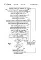
- FIG. 1is a schematic illustration of an apparatus in accordance with the present invention
- FIG. 2is a schematic illustration of an example device in which the present invention is utilized
- FIG. 3is a schematic illustration of a portion of the device shown in FIG. 2, which contains the apparatus of the present invention.
- FIG. 4is a flowchart of a process in accordance with the present invention.
- FIG. 1One representation of the present invention is schematically shown in FIG. 1 as an apparatus 10 that compensates for distortion of information data signals.
- the apparatus 10accordingly to the present invention provides pre-equalization “compensation” for information data, which is transmitted at a relatively high rate. Further, the present invention is useful for wide band applications (e.g., 18 MHz).
- the high data rate and bandwidthare related to the system environment in which the apparatus 10 is utilized. Accordingly, the apparatus 10 of the present invention may be used in any system having such demanding requirements.
- the apparatus 10is utilized in a high definition (“HD”) digital television (“DTV”) system 12 , as shown in FIG. 2 .
- the DTV system 12includes an 8VSB exciter 32 .
- the 8VSB exciter 32(FIG. 3) contains the apparatus 10 in accordance with the present invention.
- the output of the 8VSB exciter 32is provided to a transmitter 34 (e.g., UHF and/or VHF).
- a broadcast signal from a broadcast antenna 36is received at a television.
- a transmitter 34e.g., UHF and/or VHF
- a broadcast signal from a broadcast antenna 36is received at a television.
- signal timing lineswhich supply appropriate timing signals, to various components of the system (including components of the apparatus 10 ) are needed for synchronizing operation of the various components. The person of ordinary skill in the art will understand the timing operation. Accordingly, the timing lines are omitted for clarity.
- an information data streamis received (e.g., from a switcher) and proceeds to a byte formation device 42 and then to a byte randomizer device 44 .
- the information data streamproceeds through a Reed Solomon encoder 46 and through a Trellis encoder 48 .
- the information data streamproceeds through one or more filters 50 ,an adaptive non-linear corrector 52 , and a linear pre-equalizer 54 .
- the information data stream input into the linear pre-equalizer 54is comprised of 32 byte words defined within a phase amplitude modulated electrical signal.
- the linear pre-equalizer 54is a Finite Impulse Response (“FIR”) digital filter, which pre-compensates or pre-equalizes the information signal such that the output from the transmitter 34 is as desired (i.e., no linear distortion).
- the linear pre-equalizer 54may be comprised of, or include, a microprocessor that performs a program process and/or may be comprised of, or include, discrete “hard-wired” circuitry.
- the linear pre-equalizer 54is part of the apparatus 10 ,which compensates for linear distortion of the information signal, and is described in greater detail below.
- the information data streamproceeds through a digital-to-analog converter (DAC) 56 and an up converter 58 , which is driven by a local oscillator 60 .
- the information data streamproceeds from the up converter 58 through various band-limiting filters 59 toward the transmitter 34 .
- the information data stream(now analog and up-converted) is passed through a high-power transmission amplifier 62 of the transmitter 34 .
- Various band-limiting circuitssuch as matching networks, input/output filters, and antenna miss-matches distort the information signal passing through the transmitter 34 in both a non-linear and linear fashion. In other words, the system 12 is a non-ideal system.
- the output of the transmitter 34is sampled to provide a feedback sample signal.
- the feedback sample signalis indicative of the transmitter output and is provided along a feedback path.
- a coupler 64couples off the sample signal from the output of the transmitter 34 .
- the feedback sample signalpasses through a down converter 66 ,which is driven by the same local oscillator 60 as the up converter 58 (synchronous demodulation).
- the feedback sample signalpasses through an analog-to-digital (A/D) converter 68 and is provided to the adaptive non-linear corrector 52 for its non-linear correction and also to an adaptive equalization determination 70 .
- A/Danalog-to-digital
- the adaptive equalization determination 70is part of the apparatus 10 .
- Another input to the adaptive equalization determination 70is the information data signal.
- the information signalis provided to the adaptive equalization determination 70 from a point on the data stream prior to all pre-correction/pre-equalization (i.e., prior to both the non-linear corrector 52 and the linear pre-equalizer 54 ).
- the feedback sample signal and the information data signalare used to determine the amount of linear pre-equalization that the linear pre-equalizer 54 must impose upon the information signal such that the output of the transmitter 34 provides a proper, linearly correct signal.
- the adaptive equalization determination 70may be comprised of, or include, a microcomputer and/or discrete circuitry.
- the data streamis better understood. Specifically, in FIG. 1, the data stream is illustrated as being a complex input which is supplied to a non-linear corrector function 72 within the adaptive non-linear corrector 52 .
- the output of the non-linear corrector function 72is provided to a complex-to-real converter 74 .
- the output of the complex-to-real converter 74is provided to the linear pre-equalizer 54 .
- the output of the linear pre-equalizer 54is provided as the input to the DAC 56 .
- the information signalis “branched-off” of the data stream for use both in non-linear correction and linear equalization.
- the “branch-off”is off or away from the data stream. Components and activities that are present along the data stream (e.g., 72 , 74 , 54 , 56 , etc.) are online. Thus, the “branch-off” permits offline activity.
- the information signalis “branched-off” and provided as an input to a “D” (desired) memory 76 .
- the D memory 76holds the information signal as a desired result for purposes to be described below.
- the output of the D memory 76is provided to a delay 78 within the non-linear corrector 52 .
- the output from the D memory 76is also provided as a first input to a subtraction device 80 (e.g., a summation device having one additive input and one subtractive input).
- a subtraction device 80e.g., a summation device having one additive input and one
- the subtraction device 80receives a second input from a “Y” (return) memory 82 .
- the Y memory 82is located along the feedback path. Specifically, the Y memory 82 receives an output from a real-to-complex converter 84 , which, in turn, receives its input from the A/D converter 68 .
- the Y memory 82contains the information as it is output from the power amplifier 62 .
- the output of the amplifier 62is the result of pre-distortion (e.g., pre-correction/pre-equalization) by the non-linear corrector 52 and linear pre-equalizer 54 (described below), and distortion by the non-ideal system 12 that includes the transmitter 34 .
- the subtraction device 80is a means to compare the desired signal with the actual output signal, and the result of such a comparison is used by the non-linear corrector function 72 to determine a non-linear pre-distortion of the information signal.
- FIG. 1illustrates certain of the components in the “correction path steam” (i.e., outside of the information stream) as being shared by both the adaptive equalization determination 70 and the adaptive non-linear corrector 52 . It is to be appreciated by a person of ordinary skill in the art that other configurations are possible such that components are not shared, etc.
- the output of the D memory 76is provided to a complex-to-real converter 90 .
- the output of the complex-to-real converter 90is provided to a delay 92 , and the output of the delay 92 is provided to a subtraction device 94 (e.g., a summation having a positive input and a negative input).
- the output of the Y memory 82is provided to a complex-to-real converter 98 and the output of the complex-to-real converter 98 is provided to an adaptive post-equalizer or filter 96 .
- the adaptive filter 96is similar to the linear pre-equalizer 54 (i.e., both are finite impulse response or “FIR” filters).
- the adaptive filter 96may be comprised of, or include, a microprocessor that performs a program process and/or may be comprised of, or include, discrete “hard-wired” circuitry.
- the output of the adaptive filter 96is provided as a second input to the subtraction device 94 .
- the subtraction device 94is a means to compare the two input signals. The output of the subtraction device 94 is fed back into the adaptive filter 96 .
- the subtraction device 94 and the adaptive filter 96act as an adaptive post-equalizer for generating a linear pre-equalization value, which is used to compensate for the linear distortion caused by the non-ideal components, e.g., the transmitter 34 .
- any one of a number of adaptive algorithmscould be used within the adaptive filter 96 .
- One example algorithmis a least-means-square “LMS” algorithm.
- an error valueis output from the subtraction device and is derived from the two inputs (i.e., the output from the adaptive filter 96 is subtracted from the delayed, desired signal). Specifically:
- d(n)is the desired vector (i.e., from the D memory and suitably delayed via delay 92 );
- y(n)is the return or result signal (i.e., from the Y memory);
- f(n)is the correction provided by the adaptive filter 96 ;
- *is the symbol for convolving (e.g., multiplication of two frequency responses together).
- g(n)is the effect of the non-ideal system (e.g., the transmitter 34 );
- h(n)is the correction provided by the linear pre-equalizer 54 (in the information stream).
- the example LMS algorithmis:
- the convolving of the linear pre-equalizer 54 and the adaptive filter 96provides the inverse of the system effect and thus provides the optimum pre-equalization.
- the values of the adaptive filter 96are convolved with those of the linear pre-equalizer 54 .
- the values that result from the convolutionare then stored for use by the linear pre-equalizer 54 .
- the tap valuesare modified (e.g., updated).
- the means 100 for convolution of the values from the adaptive filter 96 to those of the linear pre-equalizer 54is represented in FIG.
- the structure for performing the convolution function 100may include a microprocessor performing a program and/or discrete “hard wired” circuitry.
- the adaptive equalization determination 70is outside of the information stream heading toward the transmitter 34 (i.e., offline).
- the operation of the adaptive equalization determination 70 , with its adaptive filter 96can, and does, occur at a rate that is independent of the rate of operation of the linear pre-equalizer 54 (e.g., not lock-stepped). Further, the adaptive filter 96 can, and does, continuously operate to develop the equalization, except during a convolution with the pre-equalizer 54 .
- the post-equalizationis eventually provided to the linear pre-equalizer 54 , as will be described below.
- the linear pre-equalizer 54does not change the amount of linear pre-equalization (i.e., correction) until necessary.
- the linear pre-equalizer 54operates to impose a predetermined pre-equalization until it is determined, via the feedback sample signal, that the amount of pre-equalization is no longer effective to compensate for the linear distorting propensities of the non-ideal transmitter 34 .
- the linear pre-equalizer 54does not continuously update.
- the filter 96is convolved with the linear pre-equalizer 54 .
- convolving the adaptive filter 96 and the pre-equalizeroccurs at a suitable time.
- One example of when to convolve the adaptive filter 96 and the linear pre-equalizer 54occurs when the error e(n) (the output of subtraction device 94 ) converges to zero. This occurs when the function of the adaptive filter 96 becomes an impulse response. The function of the adaptive filter 96 is routinely tested to determine whether the function has reached an impulse response status.
- the convolvingcan occur when the error is sufficiently small (i.e., the function of the adaptive filter 96 is nearly an impulse response). As yet another alternative, the convolving can occur for each predetermined number of updates. Thus, the convolution is less than continuous.
- the filter 96When it is determined to convolve the adaptive filter 96 and the linear pre-equalizer 54 , the filter 96 , which has been continuously updating a correction value, is convolved with the linear pre-equalizer 54 .
- the result of the convolvingis that the amount of pre-equalization, which will be imposed by the linear pre-equalizer 54 , is updated to the new value.
- Thishas the advantage that the linear pre-equalizer 54 does not need to continuously operate to update the amount of pre-equalization correction. This is important because the linear pre-equalizer 54 is within the information data stream.
- the adaptive filter 96which is outside of the information data stream, provides this function.
- the linear pre-equalizer 54were updated after every sample or very often as in traditional equalizers, then the data contained in the Y memory 82 would be obsolete (i.e., unusable) and data from the Y memory would need to be re-acquired after every update.
- the adaptive filter 96post-equalizer
- the adaptive filter 96(post-equalizer) can be convolved with the linear pre-equalizer 54 . After the convolving, new Y memory data is taken.
- the error signal (e(n))is always a function of the current system (i.e., includes the current pre-equalization imposed by the linear pre-equalizer 54 ).
- the adaptive filter 96can continuously be processing data, except when involved in a convolution with the linear pre-equalizer 54 .
- the capacity of the linear pre-equalizer 54can be focused upon processing the data stream, except for the relatively infrequent diversion for convolution.
- FIG. 4An example of a process 200 for deriving an adaptation for the linear pre-equalizer 54 and proceeding with a convolution to adapt, in accordance with the present invention, is shown in FIG. 4 .
- the process 200may include other preliminary step(s) such as initialization step(s).
- the process 200may include other, minor steps such as storing appropriate values to a memory device.
- the process 200begins a step 202 , wherein the adaptive equalizer determination 70 acquires the information signal (i.e., the desired signal values d(n) from the D memory). Specifically, for a system having FIR's with N filter taps, “N” samples are acquired.
- the feedback signali.e., the signal values y(n) from the Y memory
- the information signal and the feedback signalare referred to in FIG. 4 by “D” and “Y”, respectively, for shorthand purposes.
- the average energy of the feedback signalis calculated at step 206 . If desired, the average energy of the information signal is also calculated at step 206 .
- the feedback signalis scaled to equal an average of the information signal (step 208 ) and the two signals are cross-correlated (step 210 ).
- the number of sample delays between the information signal and the feedback signalis calculated.
- the delay 92is set based upon the cross-correlation delay calculation at step 214 .
- the delay “ ⁇ ”is determined based upon the following rule:
- the adaptive filter 96begins an adaptive process using the value e(n) from the subtraction device 94 .
- an LMS algorithmis used, and the values are normalized. For example:
- step 222the root-mean-square error is calculated for each iteration. Specifically:
- step 224it is queried whether the end of the information signal has been reached (i.e., it is queried if the value of m has reached the value of N). If the determination at step 224 is negative (the end has not yet been reached, in other words n is less than N), the process 200 goes to step 225 , where 1 is added to the value of n. From step 225 , the process 200 goes to step 220 . If the determination at step 224 is affirmative, the process 200 goes to step 226 . At step 226 , it is queried whether the current value of e rms is less than a previously stored value (e.g., old e rms ).
- a previously stored valuee.g., old e rms
- step 226If the determination at step 226 is negative (e.g., the current e rms is not less than old e rms ), the process 200 goes to step 228 , in which the values associated with h(n) (i.e., the pre-equalizer values) are replaced with the same values of h(n) such that the adaptation and error determination can be repeated. Upon completion of step 228 , the process loops back to step 202 .
- the values associated with h(n)i.e., the pre-equalizer values
- step 226If the determination at step 226 is affirmative (e.g., the current e rms is less than old e rms ), the process 200 goes to step 230 .
- the values for f(n) from the additive filter 96are convolved with the values h(n) of the linear pre-equalizer 54 .
- the new values resulting from the convolutionare saved to the linear pre-equalizer 54 for use to pre-distort the information signal until such a time that the values are against modified.
- step 232the process 200 loops back to step 202 .
- the steps 202 - 228 , inclusiveare preformed by the adaptive equalization determination 70 , with its adaptive filter 96 .
- the step 230is performed by the convolve function 100 .
- the step 232is preformed by the linear pre-equalizer 54 .
Landscapes
- Engineering & Computer Science (AREA)
- Physics & Mathematics (AREA)
- Nonlinear Science (AREA)
- Power Engineering (AREA)
- Computer Networks & Wireless Communication (AREA)
- Signal Processing (AREA)
- Algebra (AREA)
- General Physics & Mathematics (AREA)
- Mathematical Analysis (AREA)
- Mathematical Optimization (AREA)
- Pure & Applied Mathematics (AREA)
- Cable Transmission Systems, Equalization Of Radio And Reduction Of Echo (AREA)
- Filters That Use Time-Delay Elements (AREA)
- Amplifiers (AREA)
- Dc Digital Transmission (AREA)
Abstract
Description


Claims (21)
Priority Applications (12)
| Application Number | Priority Date | Filing Date | Title |
|---|---|---|---|
| US09/105,824US6285412B1 (en) | 1997-07-23 | 1998-06-26 | Adaptive pre-equalization apparatus for correcting linear distortion of a non-ideal data transmission system |
| JP2000504714AJP2001511631A (en) | 1997-07-23 | 1998-07-23 | Adaptive pre-equalizer for correcting linear distortion in non-ideal data communication systems |
| DE69836330TDE69836330T2 (en) | 1997-07-23 | 1998-07-23 | ADAPTIVE DIGITAL PRECORDING DEVICE FOR LINEARIZING A POWER AMPLIFIER FOR DIGITAL BROADCASTING |
| EP98934663AEP0998823B1 (en) | 1997-07-23 | 1998-07-23 | Adaptive digital predistortion apparatus for linearizing a power amplifier for digital broadcasting |
| AU84142/98AAU752776B2 (en) | 1997-07-23 | 1998-07-23 | Adaptive pre-equalization apparatus for correcting linear distortion of a non-ideal data transmission system |
| PCT/US1998/015014WO1999005869A2 (en) | 1997-07-23 | 1998-07-23 | Adaptive pre-equalization apparatus for correcting linear distortion of a non-ideal data transmission system |
| CN98808473ACN1268271A (en) | 1997-07-23 | 1998-07-23 | Adaptive pre-equalization apparatus for correcting linear distortion of a non-ideal data transmission system |
| KR1020007000731AKR100545461B1 (en) | 1997-07-23 | 1998-07-23 | Adaptive Pre-Equalization Device Corrects Linear Distortion in Atypical Data Transmission Systems |
| CA002297462ACA2297462C (en) | 1997-07-23 | 1998-07-23 | Adaptive pre-equalization apparatus for correcting linear distortion of a non-ideal data transmission system |
| BR9810788-7ABR9810788A (en) | 1997-07-23 | 1998-07-23 | Apparatus to compensate for a linear distortion action on an information signal within a transmission system |
| US09/312,354US6335767B1 (en) | 1998-06-26 | 1999-05-14 | Broadcast transmission system with distributed correction |
| US09/905,560US6519010B2 (en) | 1998-06-26 | 2001-07-13 | Broadcast transmission system with sampling and correction arrangement for correcting distortion caused by amplifying and signal conditioning components |
Applications Claiming Priority (2)
| Application Number | Priority Date | Filing Date | Title |
|---|---|---|---|
| US5348297P | 1997-07-23 | 1997-07-23 | |
| US09/105,824US6285412B1 (en) | 1997-07-23 | 1998-06-26 | Adaptive pre-equalization apparatus for correcting linear distortion of a non-ideal data transmission system |
Related Child Applications (3)
| Application Number | Title | Priority Date | Filing Date |
|---|---|---|---|
| US09/312,354Continuation-In-PartUS6335767B1 (en) | 1998-06-26 | 1999-05-14 | Broadcast transmission system with distributed correction |
| US09/312,344ContinuationUS6281936B1 (en) | 1998-06-26 | 1999-05-14 | Broadcast transmission system with sampling and correction arrangement for correcting distortion caused by amplifying and signal conditioning components |
| US09/905,560ContinuationUS6519010B2 (en) | 1998-06-26 | 2001-07-13 | Broadcast transmission system with sampling and correction arrangement for correcting distortion caused by amplifying and signal conditioning components |
Publications (1)
| Publication Number | Publication Date |
|---|---|
| US6285412B1true US6285412B1 (en) | 2001-09-04 |
Family
ID=26731918
Family Applications (1)
| Application Number | Title | Priority Date | Filing Date |
|---|---|---|---|
| US09/105,824Expired - Fee RelatedUS6285412B1 (en) | 1997-07-23 | 1998-06-26 | Adaptive pre-equalization apparatus for correcting linear distortion of a non-ideal data transmission system |
Country Status (10)
| Country | Link |
|---|---|
| US (1) | US6285412B1 (en) |
| EP (1) | EP0998823B1 (en) |
| JP (1) | JP2001511631A (en) |
| KR (1) | KR100545461B1 (en) |
| CN (1) | CN1268271A (en) |
| AU (1) | AU752776B2 (en) |
| BR (1) | BR9810788A (en) |
| CA (1) | CA2297462C (en) |
| DE (1) | DE69836330T2 (en) |
| WO (1) | WO1999005869A2 (en) |
Cited By (37)
| Publication number | Priority date | Publication date | Assignee | Title |
|---|---|---|---|---|
| US20020113905A1 (en)* | 2000-12-28 | 2002-08-22 | Lg Electronics Inc. | Linearization compensation system of digital TV relay apparatus and method thereof |
| US6515712B1 (en)* | 1999-07-31 | 2003-02-04 | Lg Information & Communications, Ltd. | Signal distortion compensating apparatus and method in digital TV translator |
| US6559898B1 (en)* | 1998-02-06 | 2003-05-06 | Zenith Electronics Corporation | Low cost VBS encoder and RF modulator for supplying VSB baseband signal to RF input of digital television receiver |
| US20030103578A1 (en)* | 2001-12-04 | 2003-06-05 | Yeh Alex C. | Method and system for determining tap gain values for a transmit frequency domain equalizer to achieve unity power gain |
| EP1318643A1 (en)* | 2001-12-05 | 2003-06-11 | Telefonaktiebolaget L M Ericsson (Publ) | Method and device for performing adaptive predistortion |
| WO2003049398A1 (en)* | 2001-12-04 | 2003-06-12 | Intersil Americas Inc. | Transmit frequency domain equalizer |
| US6600516B1 (en)* | 2000-04-21 | 2003-07-29 | Harris Corporation | Digital RF transmitter system employing both digital pre-correction and analog pre-correction |
| US6639537B1 (en)* | 2000-03-31 | 2003-10-28 | Massachusetts Institute Of Technology | Highly linear analog-to-digital conversion system and method thereof |
| US6650374B2 (en)* | 1999-12-24 | 2003-11-18 | Lg Electronics Inc. | Digital television relay system |
| US6674808B1 (en)* | 1999-12-28 | 2004-01-06 | General Dynamics Decision Systems, Inc. | Post-amplifier filter rejection equalization |
| US6674326B1 (en) | 2002-06-17 | 2004-01-06 | The Boeing Company | Digitally controllable nonlinear pre-equalizer |
| US20040008764A1 (en)* | 2002-07-09 | 2004-01-15 | Jae-Hyun Seo | Pre-equalizer, VSB transmission system using the same, and transmission method thereof |
| WO2004008707A1 (en)* | 2002-07-15 | 2004-01-22 | Nokia Corporation | Adaptive pre-equalization method and apparatus |
| KR20040025009A (en)* | 2002-09-18 | 2004-03-24 | 대한민국(전남대학교총장) | Lattice-Viterbi Joint Channel Estimation Equalizer |
| WO2003100966A3 (en)* | 2002-05-24 | 2004-07-01 | Andrew Corp | Predistortion control apparatus |
| US6799021B1 (en)* | 1997-03-17 | 2004-09-28 | Nokia Telecommunications Oy | Method and arrangement for forming an address |
| US20050059424A1 (en)* | 2001-06-26 | 2005-03-17 | Sahota Gurkanwal Singh | System and method for power control calibration and a wireless communication device |
| US20050163249A1 (en)* | 2004-01-27 | 2005-07-28 | Crestcom, Inc. | Predistortion circuit and method for compensating linear distortion in a digital RF communications transmitter |
| US20050163268A1 (en)* | 2004-01-27 | 2005-07-28 | Crestcom, Inc. | Predistortion circuit and method for compensating nonlinear distortion in a digital RF communications transmitter |
| US20050233712A1 (en)* | 2004-04-16 | 2005-10-20 | Thales Broadcast & Multimedia, Inc. | Low-frequency signal correction circuit |
| EP1709729A4 (en)* | 2004-01-27 | 2006-12-27 | Crestcom Inc | Transmitter predistortion circuit and method therefor |
| US20070242772A1 (en)* | 2006-04-13 | 2007-10-18 | Harris Corporation | Phase correction of a constant envelope signal without introducing amplitude modulation |
| US20080144709A1 (en)* | 2006-12-19 | 2008-06-19 | Crestcom, Inc. | RF transmitter with predistortion and method therefor |
| US20080285640A1 (en)* | 2007-05-15 | 2008-11-20 | Crestcom, Inc. | RF Transmitter With Nonlinear Predistortion and Method Therefor |
| US7469491B2 (en) | 2004-01-27 | 2008-12-30 | Crestcom, Inc. | Transmitter predistortion circuit and method therefor |
| US20090098828A1 (en)* | 2007-10-12 | 2009-04-16 | Harris Corporation | Communications system using adaptive filter that is selected based on output power |
| US20090097539A1 (en)* | 2007-10-12 | 2009-04-16 | Harris Corporation | Communications system using adaptive filter and variable delay before adaptive filter taps |
| US20090227215A1 (en)* | 2008-03-06 | 2009-09-10 | Crestcom, Inc. | RF Transmitter with Bias-Signal-Induced Distortion Compensation and Method Therefor |
| US7729419B1 (en)* | 2006-11-24 | 2010-06-01 | Kiomars Anvari | Reconditioning equalizer filter using convolution |
| US7729420B1 (en)* | 2006-11-24 | 2010-06-01 | Kiomars Anvari | Reconditioning equalizer filter for OFDM and non-OFDM signals |
| US8081722B1 (en) | 2008-04-04 | 2011-12-20 | Harris Corporation | Communications system and device using simultaneous wideband and in-band narrowband operation and related method |
| US8094763B1 (en) | 2007-10-12 | 2012-01-10 | Harris Corporation | Communications system using adaptive filter with adaptive update gain |
| US8098781B1 (en) | 2007-10-12 | 2012-01-17 | Harris Corporation | Communications system using adaptive filter with normalization circuit |
| US8107572B1 (en) | 2007-10-12 | 2012-01-31 | Harris Corporation | Communications system using adaptive filter for interference reduction |
| US8121236B1 (en) | 2007-10-12 | 2012-02-21 | Harris Corporation | Communications system using adaptive filter circuit using parallel adaptive filters |
| US8204164B1 (en) | 2007-10-12 | 2012-06-19 | Harris Corporation | Communications system using adaptive filter and selected adaptive filter taps |
| US10103908B1 (en)* | 2016-05-12 | 2018-10-16 | L3 Technologies Inc. | Linear equalizers for outphasing amplification |
Families Citing this family (18)
| Publication number | Priority date | Publication date | Assignee | Title |
|---|---|---|---|---|
| US6335767B1 (en)* | 1998-06-26 | 2002-01-01 | Harris Corporation | Broadcast transmission system with distributed correction |
| GB2349994B (en) | 1999-05-10 | 2003-06-04 | Intek Global Technologies Ltd | Apparatus for producing a radio-frequency signal |
| WO2000079746A1 (en)* | 1999-06-22 | 2000-12-28 | Harris Corporation | Companion nyquist filter and linear equalizer within a data transmission system |
| EP1089428B1 (en)* | 1999-09-30 | 2006-08-09 | Kabushiki Kaisha Toshiba | Nonlinear compensator |
| JP4256057B2 (en) | 1999-09-30 | 2009-04-22 | 株式会社東芝 | Nonlinear compensator |
| GB2376584B (en) | 2001-06-15 | 2005-02-16 | Wireless Systems Int Ltd | Signal correction techniques |
| GB2376583B (en)* | 2001-06-15 | 2005-01-05 | Wireless Systems Int Ltd | Time alignment of signals |
| KR100426215B1 (en)* | 2001-08-20 | 2004-04-06 | 엘지전자 주식회사 | Auto-compensation apparatus and method for linearity of transmitting system of Digital television |
| JP3707549B2 (en)* | 2002-03-22 | 2005-10-19 | 日本電気株式会社 | Transmitter |
| KR100967399B1 (en) | 2006-12-08 | 2010-07-02 | 한국전자통신연구원 | Reverse Path Compensation Device Using Tone Signal in Digital Broadcasting System and Its Method |
| WO2008069580A1 (en)* | 2006-12-08 | 2008-06-12 | Electronics And Telecommunications Research Institute | Apparatus and method for compensating feedback path distortion |
| TWI415459B (en)* | 2011-02-17 | 2013-11-11 | Mstar Semiconductor Inc | Analog tv receiver and method and associated device and method for configuring equalizer coefficients |
| CN102647568B (en)* | 2011-02-18 | 2015-04-22 | 晨星软件研发(深圳)有限公司 | Method and circuit for reducing signal distortion of analog TV signal |
| US10411917B2 (en)* | 2017-12-04 | 2019-09-10 | Credo Technology Group Limited | Linear feedback equalization |
| CN109542083B (en)* | 2018-11-16 | 2021-09-03 | 爱士惟新能源技术(江苏)有限公司 | Method, system and terminal for correcting signal of digital control system |
| GB2592678A (en)* | 2020-03-06 | 2021-09-08 | Sony Semiconductor Solutions Corp | Amplifier and amplification method |
| TWI819476B (en)* | 2022-01-25 | 2023-10-21 | 瑞昱半導體股份有限公司 | Communications device and method for compensating frequency response distortion of communication device |
| CN116667863A (en)* | 2022-02-18 | 2023-08-29 | 瑞昱半导体股份有限公司 | Communication device and method for compensating frequency response distortion of communication device |
Citations (19)
| Publication number | Priority date | Publication date | Assignee | Title |
|---|---|---|---|---|
| US4291277A (en) | 1979-05-16 | 1981-09-22 | Harris Corporation | Adaptive predistortion technique for linearizing a power amplifier for digital data systems |
| US4412337A (en) | 1981-11-04 | 1983-10-25 | Motorola Inc. | Power amplifier and envelope correction circuitry |
| US4435823A (en) | 1980-12-29 | 1984-03-06 | Harris Corporation | Adaptive equalizer capable of linear and nonlinear weighting |
| US4700151A (en) | 1985-03-20 | 1987-10-13 | Nec Corporation | Modulation system capable of improving a transmission system |
| US4947363A (en) | 1988-12-12 | 1990-08-07 | Motorola, Inc. | Pipelined processor for implementing the least-mean-squares algorithm |
| US5049832A (en) | 1990-04-20 | 1991-09-17 | Simon Fraser University | Amplifier linearization by adaptive predistortion |
| US5107520A (en) | 1989-01-24 | 1992-04-21 | U.S. Philips Corporation | Adaptive predistortion circuit for a digital transmission system |
| US5448206A (en) | 1993-07-09 | 1995-09-05 | Newhall; Edmunde E. | Systems with increased information rates using embedded sample modulation and predistortion equalization |
| US5489879A (en) | 1995-02-16 | 1996-02-06 | Seiko Communication Systems, Inc. | Amplitude and phase error normalization of subcarrier generator |
| US5590121A (en) | 1995-03-30 | 1996-12-31 | Lucent Technologies Inc. | Method and apparatus for adaptive filtering |
| US5732333A (en) | 1996-02-14 | 1998-03-24 | Glenayre Electronics, Inc. | Linear transmitter using predistortion |
| US5745006A (en) | 1996-11-12 | 1998-04-28 | Motorola, Inc. | Method of compensating for distortion in an amplifier |
| US5748678A (en)* | 1995-07-13 | 1998-05-05 | Motorola, Inc. | Radio communications apparatus |
| US5751766A (en)* | 1995-04-27 | 1998-05-12 | Applied Signal Technology, Inc. | Non-invasive digital communications test system |
| US5910965A (en)* | 1995-06-30 | 1999-06-08 | Harris Corporation | Adaptive predistortion using over-the-hop feedback |
| US5959500A (en)* | 1998-01-26 | 1999-09-28 | Glenayre Electronics, Inc. | Model-based adaptive feedforward amplifier linearizer |
| US6054895A (en)* | 1997-08-27 | 2000-04-25 | Harris Corporation | Apparatus and method for pre-distortion correction of a power amplifier stage |
| US6075411A (en)* | 1997-12-22 | 2000-06-13 | Telefonaktiebolaget Lm Ericsson | Method and apparatus for wideband predistortion linearization |
| US6104241A (en)* | 1998-11-18 | 2000-08-15 | Spectrian | High efficiency feed-forward RF power amplifier with predistoration enchancement |
- 1998
- 1998-06-26USUS09/105,824patent/US6285412B1/ennot_activeExpired - Fee Related
- 1998-07-23JPJP2000504714Apatent/JP2001511631A/enactivePending
- 1998-07-23AUAU84142/98Apatent/AU752776B2/ennot_activeCeased
- 1998-07-23EPEP98934663Apatent/EP0998823B1/ennot_activeExpired - Lifetime
- 1998-07-23CACA002297462Apatent/CA2297462C/ennot_activeExpired - Fee Related
- 1998-07-23WOPCT/US1998/015014patent/WO1999005869A2/enactiveIP Right Grant
- 1998-07-23CNCN98808473Apatent/CN1268271A/enactivePending
- 1998-07-23BRBR9810788-7Apatent/BR9810788A/ennot_activeIP Right Cessation
- 1998-07-23DEDE69836330Tpatent/DE69836330T2/ennot_activeExpired - Lifetime
- 1998-07-23KRKR1020007000731Apatent/KR100545461B1/ennot_activeExpired - Fee Related
Patent Citations (19)
| Publication number | Priority date | Publication date | Assignee | Title |
|---|---|---|---|---|
| US4291277A (en) | 1979-05-16 | 1981-09-22 | Harris Corporation | Adaptive predistortion technique for linearizing a power amplifier for digital data systems |
| US4435823A (en) | 1980-12-29 | 1984-03-06 | Harris Corporation | Adaptive equalizer capable of linear and nonlinear weighting |
| US4412337A (en) | 1981-11-04 | 1983-10-25 | Motorola Inc. | Power amplifier and envelope correction circuitry |
| US4700151A (en) | 1985-03-20 | 1987-10-13 | Nec Corporation | Modulation system capable of improving a transmission system |
| US4947363A (en) | 1988-12-12 | 1990-08-07 | Motorola, Inc. | Pipelined processor for implementing the least-mean-squares algorithm |
| US5107520A (en) | 1989-01-24 | 1992-04-21 | U.S. Philips Corporation | Adaptive predistortion circuit for a digital transmission system |
| US5049832A (en) | 1990-04-20 | 1991-09-17 | Simon Fraser University | Amplifier linearization by adaptive predistortion |
| US5448206A (en) | 1993-07-09 | 1995-09-05 | Newhall; Edmunde E. | Systems with increased information rates using embedded sample modulation and predistortion equalization |
| US5489879A (en) | 1995-02-16 | 1996-02-06 | Seiko Communication Systems, Inc. | Amplitude and phase error normalization of subcarrier generator |
| US5590121A (en) | 1995-03-30 | 1996-12-31 | Lucent Technologies Inc. | Method and apparatus for adaptive filtering |
| US5751766A (en)* | 1995-04-27 | 1998-05-12 | Applied Signal Technology, Inc. | Non-invasive digital communications test system |
| US5910965A (en)* | 1995-06-30 | 1999-06-08 | Harris Corporation | Adaptive predistortion using over-the-hop feedback |
| US5748678A (en)* | 1995-07-13 | 1998-05-05 | Motorola, Inc. | Radio communications apparatus |
| US5732333A (en) | 1996-02-14 | 1998-03-24 | Glenayre Electronics, Inc. | Linear transmitter using predistortion |
| US5745006A (en) | 1996-11-12 | 1998-04-28 | Motorola, Inc. | Method of compensating for distortion in an amplifier |
| US6054895A (en)* | 1997-08-27 | 2000-04-25 | Harris Corporation | Apparatus and method for pre-distortion correction of a power amplifier stage |
| US6075411A (en)* | 1997-12-22 | 2000-06-13 | Telefonaktiebolaget Lm Ericsson | Method and apparatus for wideband predistortion linearization |
| US5959500A (en)* | 1998-01-26 | 1999-09-28 | Glenayre Electronics, Inc. | Model-based adaptive feedforward amplifier linearizer |
| US6104241A (en)* | 1998-11-18 | 2000-08-15 | Spectrian | High efficiency feed-forward RF power amplifier with predistoration enchancement |
Non-Patent Citations (2)
| Title |
|---|
| Saleh A A M et al: "Adaptive Linearization of Power Amplifiers in Digital Radio Systems" Bell System Technical Journal, vol. 62, No. 4, Part 01, Apr. 1983, pp. 1019-1033, XP002028354. |
| Wright Andrew S; Durtler William G: "Experimental Performance of an Adaptive Digital Linearized Power Amplifier" IEEE MTT-S International Microwave Symposium Digest, vol. 2, Jun. 1-5, 1992, pp. 1105-1108, XP000343487 Albuquerque, NM, USA. |
Cited By (51)
| Publication number | Priority date | Publication date | Assignee | Title |
|---|---|---|---|---|
| US6799021B1 (en)* | 1997-03-17 | 2004-09-28 | Nokia Telecommunications Oy | Method and arrangement for forming an address |
| US6559898B1 (en)* | 1998-02-06 | 2003-05-06 | Zenith Electronics Corporation | Low cost VBS encoder and RF modulator for supplying VSB baseband signal to RF input of digital television receiver |
| US6515712B1 (en)* | 1999-07-31 | 2003-02-04 | Lg Information & Communications, Ltd. | Signal distortion compensating apparatus and method in digital TV translator |
| US6650374B2 (en)* | 1999-12-24 | 2003-11-18 | Lg Electronics Inc. | Digital television relay system |
| US6674808B1 (en)* | 1999-12-28 | 2004-01-06 | General Dynamics Decision Systems, Inc. | Post-amplifier filter rejection equalization |
| US6639537B1 (en)* | 2000-03-31 | 2003-10-28 | Massachusetts Institute Of Technology | Highly linear analog-to-digital conversion system and method thereof |
| US6600516B1 (en)* | 2000-04-21 | 2003-07-29 | Harris Corporation | Digital RF transmitter system employing both digital pre-correction and analog pre-correction |
| US20020113905A1 (en)* | 2000-12-28 | 2002-08-22 | Lg Electronics Inc. | Linearization compensation system of digital TV relay apparatus and method thereof |
| US6917389B2 (en)* | 2000-12-28 | 2005-07-12 | Lg Electronics Inc. | Linearization compensation system of digital TV relay apparatus and method thereof |
| US8457570B2 (en)* | 2001-06-26 | 2013-06-04 | Qualcomm, Incorporated | System and method for power control calibration and a wireless communication device |
| US20050059424A1 (en)* | 2001-06-26 | 2005-03-17 | Sahota Gurkanwal Singh | System and method for power control calibration and a wireless communication device |
| WO2003049398A1 (en)* | 2001-12-04 | 2003-06-12 | Intersil Americas Inc. | Transmit frequency domain equalizer |
| US7103112B2 (en) | 2001-12-04 | 2006-09-05 | Conexant, Inc. | Transmit frequency domain equalizer |
| US20030103578A1 (en)* | 2001-12-04 | 2003-06-05 | Yeh Alex C. | Method and system for determining tap gain values for a transmit frequency domain equalizer to achieve unity power gain |
| EP1318643A1 (en)* | 2001-12-05 | 2003-06-11 | Telefonaktiebolaget L M Ericsson (Publ) | Method and device for performing adaptive predistortion |
| WO2003100966A3 (en)* | 2002-05-24 | 2004-07-01 | Andrew Corp | Predistortion control apparatus |
| US20060033567A1 (en)* | 2002-05-24 | 2006-02-16 | Smithson Antony J | Predistortion control apparatus |
| US7279972B2 (en) | 2002-05-24 | 2007-10-09 | Andrew Corporation | Predistortion control apparatus |
| US6674326B1 (en) | 2002-06-17 | 2004-01-06 | The Boeing Company | Digitally controllable nonlinear pre-equalizer |
| US20040008764A1 (en)* | 2002-07-09 | 2004-01-15 | Jae-Hyun Seo | Pre-equalizer, VSB transmission system using the same, and transmission method thereof |
| US7406132B2 (en) | 2002-07-09 | 2008-07-29 | Electronics And Telecommunications Research Institute | Pre-equalizer, VSB transmission system using the same, and transmission method thereof |
| KR100471592B1 (en)* | 2002-07-09 | 2005-03-10 | 한국전자통신연구원 | Pre-equalizer, VSB transmission system using the pre-equalizer and transmission method thereof |
| US20060056327A1 (en)* | 2002-07-15 | 2006-03-16 | Edmund Coersmeier | Adaptive pre-equalization method and apparatus |
| WO2004008707A1 (en)* | 2002-07-15 | 2004-01-22 | Nokia Corporation | Adaptive pre-equalization method and apparatus |
| KR20040025009A (en)* | 2002-09-18 | 2004-03-24 | 대한민국(전남대학교총장) | Lattice-Viterbi Joint Channel Estimation Equalizer |
| US20050163268A1 (en)* | 2004-01-27 | 2005-07-28 | Crestcom, Inc. | Predistortion circuit and method for compensating nonlinear distortion in a digital RF communications transmitter |
| EP1709729A4 (en)* | 2004-01-27 | 2006-12-27 | Crestcom Inc | Transmitter predistortion circuit and method therefor |
| US20050163249A1 (en)* | 2004-01-27 | 2005-07-28 | Crestcom, Inc. | Predistortion circuit and method for compensating linear distortion in a digital RF communications transmitter |
| US7430248B2 (en) | 2004-01-27 | 2008-09-30 | Crestcom, Inc. | Predistortion circuit and method for compensating nonlinear distortion in a digital RF communications transmitter |
| US7469491B2 (en) | 2004-01-27 | 2008-12-30 | Crestcom, Inc. | Transmitter predistortion circuit and method therefor |
| US20050233712A1 (en)* | 2004-04-16 | 2005-10-20 | Thales Broadcast & Multimedia, Inc. | Low-frequency signal correction circuit |
| US20070242772A1 (en)* | 2006-04-13 | 2007-10-18 | Harris Corporation | Phase correction of a constant envelope signal without introducing amplitude modulation |
| US7782978B2 (en) | 2006-04-13 | 2010-08-24 | Harris Corporation | Phase correction of a constant envelope signal without introducing amplitude modulation |
| US7729419B1 (en)* | 2006-11-24 | 2010-06-01 | Kiomars Anvari | Reconditioning equalizer filter using convolution |
| US7729420B1 (en)* | 2006-11-24 | 2010-06-01 | Kiomars Anvari | Reconditioning equalizer filter for OFDM and non-OFDM signals |
| US20080144709A1 (en)* | 2006-12-19 | 2008-06-19 | Crestcom, Inc. | RF transmitter with predistortion and method therefor |
| US7724840B2 (en) | 2006-12-19 | 2010-05-25 | Crestcom, Inc. | RF transmitter with predistortion and method therefor |
| US20080285640A1 (en)* | 2007-05-15 | 2008-11-20 | Crestcom, Inc. | RF Transmitter With Nonlinear Predistortion and Method Therefor |
| US8107572B1 (en) | 2007-10-12 | 2012-01-31 | Harris Corporation | Communications system using adaptive filter for interference reduction |
| US20090098828A1 (en)* | 2007-10-12 | 2009-04-16 | Harris Corporation | Communications system using adaptive filter that is selected based on output power |
| US7860200B2 (en) | 2007-10-12 | 2010-12-28 | Harris Corporation | Communications system using adaptive filter that is selected based on output power |
| US7864835B2 (en) | 2007-10-12 | 2011-01-04 | Harris Corporation | Communications system using adaptive filter and variable delay before adaptive filter taps |
| US8094763B1 (en) | 2007-10-12 | 2012-01-10 | Harris Corporation | Communications system using adaptive filter with adaptive update gain |
| US8098781B1 (en) | 2007-10-12 | 2012-01-17 | Harris Corporation | Communications system using adaptive filter with normalization circuit |
| US20090097539A1 (en)* | 2007-10-12 | 2009-04-16 | Harris Corporation | Communications system using adaptive filter and variable delay before adaptive filter taps |
| US8121236B1 (en) | 2007-10-12 | 2012-02-21 | Harris Corporation | Communications system using adaptive filter circuit using parallel adaptive filters |
| US8204164B1 (en) | 2007-10-12 | 2012-06-19 | Harris Corporation | Communications system using adaptive filter and selected adaptive filter taps |
| US8064851B2 (en)* | 2008-03-06 | 2011-11-22 | Crestcom, Inc. | RF transmitter with bias-signal-induced distortion compensation and method therefor |
| US20090227215A1 (en)* | 2008-03-06 | 2009-09-10 | Crestcom, Inc. | RF Transmitter with Bias-Signal-Induced Distortion Compensation and Method Therefor |
| US8081722B1 (en) | 2008-04-04 | 2011-12-20 | Harris Corporation | Communications system and device using simultaneous wideband and in-band narrowband operation and related method |
| US10103908B1 (en)* | 2016-05-12 | 2018-10-16 | L3 Technologies Inc. | Linear equalizers for outphasing amplification |
Also Published As
| Publication number | Publication date |
|---|---|
| JP2001511631A (en) | 2001-08-14 |
| KR20010022159A (en) | 2001-03-15 |
| EP0998823A2 (en) | 2000-05-10 |
| EP0998823B1 (en) | 2006-11-02 |
| AU8414298A (en) | 1999-02-16 |
| AU752776B2 (en) | 2002-09-26 |
| WO1999005869A2 (en) | 1999-02-04 |
| CA2297462C (en) | 2008-01-22 |
| CA2297462A1 (en) | 1999-02-04 |
| KR100545461B1 (en) | 2006-01-24 |
| CN1268271A (en) | 2000-09-27 |
| WO1999005869A3 (en) | 1999-04-08 |
| DE69836330D1 (en) | 2006-12-14 |
| DE69836330T2 (en) | 2007-06-14 |
| BR9810788A (en) | 2002-01-02 |
Similar Documents
| Publication | Publication Date | Title |
|---|---|---|
| US6285412B1 (en) | Adaptive pre-equalization apparatus for correcting linear distortion of a non-ideal data transmission system | |
| KR100706286B1 (en) | Broadcast transmission system with sampling and correction device for correcting distortion caused by amplification and signal conditioning components | |
| US6563868B1 (en) | Method and apparatus for adaptive equalization in the presence of large multipath echoes | |
| AU742772B2 (en) | Adaptive pre-distortion apparatus for linearizing an amplifier output within a data transmission system | |
| KR950006765B1 (en) | Method and apparatus for updating coefficients in a complex adaptive equalizer | |
| EP1181771B1 (en) | Broadcast transmission system with distributed correction | |
| US6519010B2 (en) | Broadcast transmission system with sampling and correction arrangement for correcting distortion caused by amplifying and signal conditioning components | |
| US6515712B1 (en) | Signal distortion compensating apparatus and method in digital TV translator | |
| US6829298B1 (en) | Signal processing circuit for a digital signal receiving system | |
| US4847797A (en) | Adaptive blind equilization method and device | |
| US6473133B1 (en) | Broadcast transmission system with correction for distortion caused by amplifying and signal conditioning components at a different rate | |
| KR100442818B1 (en) | Sequential Update Adaptive Equalizer and Method | |
| KR100253205B1 (en) | Non linear amplitude precorrection for hdtv transmitter | |
| CN1206251A (en) | Adaptive pre-distortion apparatus for linearizing amplifier output within data transmission system | |
| US5550862A (en) | Method and apparatus for centering equalizer taps | |
| KR100311522B1 (en) | Distortion Signal Compensation Method and Device in Digital TV | |
| WO2000079746A1 (en) | Companion nyquist filter and linear equalizer within a data transmission system |
Legal Events
| Date | Code | Title | Description |
|---|---|---|---|
| AS | Assignment | Owner name:HARRIS CORPORATION, FLORIDA Free format text:ASSIGNMENT OF ASSIGNORS INTEREST;ASSIGNOR:TWITCHELL, EDWIN RAY;REEL/FRAME:009372/0661 Effective date:19980702 | |
| FPAY | Fee payment | Year of fee payment:4 | |
| FPAY | Fee payment | Year of fee payment:8 | |
| AS | Assignment | Owner name:HBC SOLUTIONS, INC., COLORADO Free format text:ASSIGNMENT OF ASSIGNORS INTEREST;ASSIGNORS:HARRIS CORPORATION;EAGLE TECHNOLOGY INC.;REEL/FRAME:029759/0416 Effective date:20130204 | |
| AS | Assignment | Owner name:WILMINGTON TRUST, NATIONAL ASSOCIATION, MINNESOTA Free format text:SECURITY AGREEMENT;ASSIGNOR:HB CANADA COMMUNICATIONS LTD;REEL/FRAME:030156/0751 Effective date:20130329 Owner name:WILMINGTON TRUST, NATIONAL ASSOCIATION, MINNESOTA Free format text:SECURITY AGREEMENT;ASSIGNOR:HBC SOLUTIONS, INC.;REEL/FRAME:030156/0636 Effective date:20130204 | |
| AS | Assignment | Owner name:PNC BANK, NATIONAL ASSOCIATION, AS AGENT, NEW JERS Free format text:SECURITY AGREEMENT;ASSIGNOR:HBC SOLUTIONS, INC.;REEL/FRAME:030192/0355 Effective date:20130204 | |
| REMI | Maintenance fee reminder mailed | ||
| AS | Assignment | Owner name:HBC SOLUTIONS, INC., COLORADO Free format text:ASSIGNMENT OF ASSIGNORS INTEREST;ASSIGNORS:HARRIS CORPORATION;EAGLE TECHNOLOGY, LLC;REEL/FRAME:030333/0671 Effective date:20130204 | |
| LAPS | Lapse for failure to pay maintenance fees | ||
| STCH | Information on status: patent discontinuation | Free format text:PATENT EXPIRED DUE TO NONPAYMENT OF MAINTENANCE FEES UNDER 37 CFR 1.362 | |
| FP | Lapsed due to failure to pay maintenance fee | Effective date:20130904 |