US6283993B1 - Annuloplasty ring delivery system - Google Patents
Annuloplasty ring delivery systemDownload PDFInfo
- Publication number
- US6283993B1 US6283993B1US09/085,944US8594498DUS6283993B1US 6283993 B1US6283993 B1US 6283993B1US 8594498 DUS8594498 DUS 8594498DUS 6283993 B1US6283993 B1US 6283993B1
- Authority
- US
- United States
- Prior art keywords
- holder
- combination
- annuloplasty ring
- suture
- guide
- Prior art date
- Legal status (The legal status is an assumption and is not a legal conclusion. Google has not performed a legal analysis and makes no representation as to the accuracy of the status listed.)
- Expired - Lifetime
Links
Images


Classifications
- A—HUMAN NECESSITIES
- A61—MEDICAL OR VETERINARY SCIENCE; HYGIENE
- A61B—DIAGNOSIS; SURGERY; IDENTIFICATION
- A61B17/00—Surgical instruments, devices or methods
- A61B17/04—Surgical instruments, devices or methods for suturing wounds; Holders or packages for needles or suture materials
- A61B17/0482—Needle or suture guides
- A—HUMAN NECESSITIES
- A61—MEDICAL OR VETERINARY SCIENCE; HYGIENE
- A61B—DIAGNOSIS; SURGERY; IDENTIFICATION
- A61B90/00—Instruments, implements or accessories specially adapted for surgery or diagnosis and not covered by any of the groups A61B1/00 - A61B50/00, e.g. for luxation treatment or for protecting wound edges
- A—HUMAN NECESSITIES
- A61—MEDICAL OR VETERINARY SCIENCE; HYGIENE
- A61F—FILTERS IMPLANTABLE INTO BLOOD VESSELS; PROSTHESES; DEVICES PROVIDING PATENCY TO, OR PREVENTING COLLAPSING OF, TUBULAR STRUCTURES OF THE BODY, e.g. STENTS; ORTHOPAEDIC, NURSING OR CONTRACEPTIVE DEVICES; FOMENTATION; TREATMENT OR PROTECTION OF EYES OR EARS; BANDAGES, DRESSINGS OR ABSORBENT PADS; FIRST-AID KITS
- A61F2/00—Filters implantable into blood vessels; Prostheses, i.e. artificial substitutes or replacements for parts of the body; Appliances for connecting them with the body; Devices providing patency to, or preventing collapsing of, tubular structures of the body, e.g. stents
- A61F2/02—Prostheses implantable into the body
- A61F2/24—Heart valves ; Vascular valves, e.g. venous valves; Heart implants, e.g. passive devices for improving the function of the native valve or the heart muscle; Transmyocardial revascularisation [TMR] devices; Valves implantable in the body
- A61F2/2442—Annuloplasty rings or inserts for correcting the valve shape; Implants for improving the function of a native heart valve
- A61F2/2445—Annuloplasty rings in direct contact with the valve annulus
- A61F2/2448—D-shaped rings
- A—HUMAN NECESSITIES
- A61—MEDICAL OR VETERINARY SCIENCE; HYGIENE
- A61F—FILTERS IMPLANTABLE INTO BLOOD VESSELS; PROSTHESES; DEVICES PROVIDING PATENCY TO, OR PREVENTING COLLAPSING OF, TUBULAR STRUCTURES OF THE BODY, e.g. STENTS; ORTHOPAEDIC, NURSING OR CONTRACEPTIVE DEVICES; FOMENTATION; TREATMENT OR PROTECTION OF EYES OR EARS; BANDAGES, DRESSINGS OR ABSORBENT PADS; FIRST-AID KITS
- A61F2/00—Filters implantable into blood vessels; Prostheses, i.e. artificial substitutes or replacements for parts of the body; Appliances for connecting them with the body; Devices providing patency to, or preventing collapsing of, tubular structures of the body, e.g. stents
- A61F2/02—Prostheses implantable into the body
- A61F2/24—Heart valves ; Vascular valves, e.g. venous valves; Heart implants, e.g. passive devices for improving the function of the native valve or the heart muscle; Transmyocardial revascularisation [TMR] devices; Valves implantable in the body
- A61F2/2442—Annuloplasty rings or inserts for correcting the valve shape; Implants for improving the function of a native heart valve
- A61F2/2466—Delivery devices therefor
- A—HUMAN NECESSITIES
- A61—MEDICAL OR VETERINARY SCIENCE; HYGIENE
- A61B—DIAGNOSIS; SURGERY; IDENTIFICATION
- A61B50/00—Containers, covers, furniture or holders specially adapted for surgical or diagnostic appliances or instruments, e.g. sterile covers
- A61B50/20—Holders specially adapted for surgical or diagnostic appliances or instruments
- Y—GENERAL TAGGING OF NEW TECHNOLOGICAL DEVELOPMENTS; GENERAL TAGGING OF CROSS-SECTIONAL TECHNOLOGIES SPANNING OVER SEVERAL SECTIONS OF THE IPC; TECHNICAL SUBJECTS COVERED BY FORMER USPC CROSS-REFERENCE ART COLLECTIONS [XRACs] AND DIGESTS
- Y10—TECHNICAL SUBJECTS COVERED BY FORMER USPC
- Y10S—TECHNICAL SUBJECTS COVERED BY FORMER USPC CROSS-REFERENCE ART COLLECTIONS [XRACs] AND DIGESTS
- Y10S623/00—Prosthesis, i.e. artificial body members, parts thereof, or aids and accessories therefor
- Y10S623/90—Stent for heart valve
- Y—GENERAL TAGGING OF NEW TECHNOLOGICAL DEVELOPMENTS; GENERAL TAGGING OF CROSS-SECTIONAL TECHNOLOGIES SPANNING OVER SEVERAL SECTIONS OF THE IPC; TECHNICAL SUBJECTS COVERED BY FORMER USPC CROSS-REFERENCE ART COLLECTIONS [XRACs] AND DIGESTS
- Y10—TECHNICAL SUBJECTS COVERED BY FORMER USPC
- Y10S—TECHNICAL SUBJECTS COVERED BY FORMER USPC CROSS-REFERENCE ART COLLECTIONS [XRACs] AND DIGESTS
- Y10S623/00—Prosthesis, i.e. artificial body members, parts thereof, or aids and accessories therefor
- Y10S623/902—Method of implanting
- Y10S623/904—Heart
Definitions
- suturesare placed in the various layers of tissue to draw the two edges of the wound together so that the healing process can reform a smooth and competent surface.
- suturesoften tear through the tissue if they are subjected to stress, thus damaging the surgical closure of the wound. It would be desirable in many instances to have a means for lending permanent support to strengthen and support the wall of the organ into which the surgical incision has been placed. Alternatively, in many instances it would be preferred to have a biodegradable suture guide.
- the incisionis not a straight line, but is shaped to conform to an anatomical requirement, making it difficult for the surgeon to balance the tension on the sutures to form the desired shape.
- the suture lineis substantially curvilinear and it is of utmost importance that the suture line maintain a predetermined dimension. For example, when two blood vessels, or other vessels, such as intestines, are sutured together, the need exists for some means of preventing the suture line from constricting the vessel so as to create a potential point of blockage. Similar problems arise during bowel and bronchial resection.
- the surgeonmay desire to assure that the suture line is limited to a predetermined length.
- a suture guideto aid the surgeon in achieving the desired dimension of the surgical closure and/or to rigidly support the area where the sutures are placed, thus avoiding the danger that the sutures will tear through the tissue or that the suture line will act like a draw string and undesirably bunch up the tissue.
- Heart valvesDiseases and certain natural defects to heart valves can impair the functioning of the cusps of the valves in preventing regurgitation of blood from the ventricle into the atrium when the ventricle contracts.
- rheumatic fever and bacterial inflammations of the heart tissuecan distort or dilate the valvular annulus, thus resulting in displacement of the cusps away from the center of the valve and causing leakage of blood during ventricle contraction.
- annuloplastyTwo techniques, generally known as annuloplasty, are used to reshape the distended and/or deformed valve annulus.
- the circumference of the valve annulusis reduced by implanting a rigid or semi-rigid prosthetic ring of reduced circumference about the base of the annulus while the annulus is pleated to reduce its circumference to that of the ring.
- the technique known as “reconstruction”the circumference of the annulus is not reduced, but the annulus is restructured into an elongate shape.
- a rigid or semi-rigid ringhaving the same circumference as the annulus but in an elongate or elliptical shape is surgically implanted about the base of the valve. Both plication and restructuring are intended to eliminate the gap in the closure of the distended valve by bringing back together the tips of the valve cusps.
- prosthesesare annular or partially annular shaped members that fit about the base of the valve annulus.
- the prostheseswere designed as rigid frame members, or “rings”, of metallic or other rigid materials that flex little, if at all, during the normal opening and closing of the valve. Since a normal heart valve annulus continuously flexes during the cardiac cycle, a rigid ring prosthesis interferes with this movement and thereby restricts movement of the valve itself. Sutures used to implant rigid ring prostheses consequently undergo stresses sufficient to tear the sutures loose. Examples of rigid annuloplasty ring prostheses are disclosed in U.S. Pat. Nos. 3,656,185, issued to Carpentier on Apr. 18, 1972; and 4,164,046, issued to Cooley on Aug. 14, 1979.
- Flexible prosthesesgenerally include an inner support member formed from a flexible material. This support member is wrapped in woven, biocompatible cloth material. Realignment of the valve cusps during opening and closing of the valve is obtained by the proper suturing of the ring about the valve annulus.
- completely flexible ring prosthesesprovide almost no support to the suture area during the precarious implant procedure. Even though the surgeon attempts to evenly distribute the sutures along the periphery of the valvular annulus, during implant the draw-string effect of the sutures tends to bunch the material covering the flexible ring so that the sutures also bunch together at localized areas around the ring. This phenomenon, known as multiple plications in the heart valve annulus, causes rigid areas around the annulus. Thus, the flexible ring actually ends by imparting areas of rigidity and thereby distorts the valve annulus during the opening and closing of the valve despite the desired reduction in circumference of the valvular annulus.
- annuloplasty prosthesesTo overcome some of the drawbacks of rigid ring prostheses, still further types of annuloplasty prostheses have been designed to allow for adjustment of the ring circumference, either by the surgeon during implant, or automatically as the implanted ring moves during the opening and closing of the valve.
- This type of adjustable prosthesisis typically designed in combination with a rigid, or at least partially rigid, frame.
- U.S. Pat. No. 4,055,861issued to Carpentier on Nov. 1, 1977, teaches an annuloplasty ring prosthesis having a flexibility between the completely flexible rings discussed above and the various types of rigid ring.
- the ring of Carpentieris deformable to an equal degree and simultaneously in all directions and preferably has the elasticity of an annular bundle of 2 to 8 turns of a cylindrical bristle of poly(ethylene terephthalate).
- annuloplasty ringseliminate the bunching caused by flexible rings, the restrictive nature of such rings is generally detrimental to the valve's ability to open and close normally. It thus remains an object of the invention to provide a surgical means for reshaping a deformed or dilated heart valve annulus having none of the above described drawbacks associated with known annuloplasty ring prostheses.
- a suture guidebe entirely flexible, light weight, and compliant while having sufficient strength to withstand stress placed upon the sutures sewn through and around it.
- an entirely flexible suture guidecannot prevent bunching of the tissue in the draw-string effect described above and thus cannot assure that the suture line and the tissue into which it is placed will maintain any desired dimension, for example, a desired circumference. Therefore the need exists for a means of temporarily providing rigidity and fixed dimension to the suture guide during the surgery, but rendering the suture guide freely flexible once the surgery has been accomplished.
- FIG. 1is a perspective exploded view of a flexible suture guide mounted on a rigid holder assembly in accordance with an embodiment of the invention
- FIG. 1Ais a top view in partial cross-section of a length of a flexible suture guide in accordance with the present invention.
- FIG. 1Bis a top view in partial cross-section of the flexible suture guide of the present invention sutured into a ring configuration.
- FIG. 2is an exploded view of the guide mount portion and lower part of the handle portion of the holder assembly of FIG. 1 without the suture guide.
- FIG. 3is a perspective view of a flexible suture guide of the present invention mounted on the assembled guide mount and lower handle portions seen in FIG. 2 .
- FIG. 4is a cross-sectional view of the assembled guide mount and lower handle portions of FIG. 3 along line 4 — 4 .
- FIG. 5is a top view of the guide mount seen in FIG. 3 with a flexible suture guide tautly secured thereto.
- FIG. 6is a perspective view of a guide mount in accordance with another embodiment of the invention.
- FIG. 7is a cross-sectional view of a suture guide having a lenticular cross-sectional shape in accordance with another embodiment of the invention.
- FIG. 8is a side perspective sectional view of a handle assembly in accordance with another embodiment of the invention.
- FIG. 9is a bottom view of the handle extension of FIG. 8 .
- FIG. 10is a top view of the housing of FIG. 8 .
- FIG. 11is a perspective view of a suture guide holder in accordance with another embodiment of the invention.
- FIG. 12is an exploded view of the guide mount portion and lower handle portion of the suture guide holder of FIG. 11 .
- FIG. 13is a top view of the guide mount portion of the suture guide holder of FIG. 11 .
- FIG. 14is a perspective view of a linear suture guide holder in accordance with another embodiment of the invention.
- FIG. 15is a perspective view of the suture guide holder of FIG. 14 with a suture guide attached.
- FIG. 16is a perspective view of a circular suture guide holder in accordance with another embodiment of the invention.
- FIG. 17is a perspective view of the suture guide holder of FIG. 16 with a suture guide attached.
- FIG. 18is a cross-sectional view of the suture guide and holder of FIG. 17 taken along line 18 — 18 .
- the present inventionovercomes the above discussed disadvantages by providing an assembly for holding a substantially flexible suture guide in a substantially taut position for placing a suture line having a predetermined dimension.
- the flexible suture guideassumes a shape or geometry, such as a circumference, that conforms to the shape or geometry of that portion of the body organ or vessel that is being sutured.
- the holder assemblycan be formed to hold the suture guide in any desired shape, whether straight, curvilinear, or a combination of the two and the suture guide can be either biodegradable or permanently implantable.
- the surgeon undertaking reconstructive surgeryis aided in achieving a suture line of any desired shape, geometry and/or dimension.
- the assemblyincludes a holder portion having a surface against which the suture guide is positioned and held tautly in a fixed shape, geometry and/or dimension. More particularly, the holder assembly includes a body having an outwardly facing surface, generally flat, against which the suture guide is tautly positioned so that the suture guide assumes the shape, geometry and/or dimension desired for the suture line. Preferably, this surface is formed with at least one depression for receiving a portion of the suture guide.
- the assemblyfurther includes a detachable handle and a mechanism for releasably binding the suture guide to the surface.
- the flexible suture guide used with the assembly of the inventioncomprises a generally elongated flexible body element having an internal flexible rib encased within a biocompatible covering, such as a woven cloth material.
- the suture guidecan be formed of either biodegradable or non-biodegradable materials depending upon whether its purpose is to serve as a permanent support to prevent tearing out of the sutures placed through it or whether the suture-supporting function is to be a temporary one.
- the suture guideserves as a rigid support and template by which the surgeon controls the length of the finished suture line.
- the combination of suture guide and holderassure that the circumference of the surgical jointure is substantially similar to the circumference of the nearby regions of the colon, rather than smaller or larger.
- the holder deviceis designed to lend a temporary rigidity or tautness to the suture guide while lending to it a shape selected to facilitate the suturing task. For instance, when the task is to place a line of sutures around the circumference of a curvilinear surface, the holder is designed to fit around at least a portion of the circumference while holding the suture guide against the said circumference to aid the surgeon in making a surgical jointure that does not distort the said circumference.
- the suture guideis releasably retained against the outwardly facing body surface by a means for releasable attachment, for example one or more threads, pieces of VelcroTM, and the like, placed so that the suture guide lies along and temporarily substantially assumes the shape of the body.
- the means for attachmentmay also be a biodegradable adhesive having the capacity to firmly attach the suture guide to the holder body for sufficient time to complete the surgery, but having the capacity to dissolve or be dissolved once the suture line has been placed.
- the threadattaches the suture guide to the body surface at least at two points, for example at its extreme ends, by passing at least partially through the suture guide and about the body, i.e., by means of an in and out stitch or stitches.
- the means for releasable attachment of the suture guide to the bodymust be such that the suture guide can be released from the body once the suture line has been placed by the surgeon without disturbing the sutures sufficiently to cause dislocation or tearing of the sutures through the tissue.
- the means for releasable attachmentis one or more threads
- a portion of the thread(s) affixing the suture guide to the bodycan be positioned to be cut by scissors, or the like, to freely release the suture guide from the body. When the thread or threads are cut or otherwise ruptured, the suture guide is freely released from the body.
- the present inventionis directed to a holder assembly for holding a substantially flexible, implantable suture guide in a substantially taut position for suturing along a suture line having a desired shape or dimension, such as the desired circumference to which an enlarged heart valve annulus is to be reduced by the formation of pleats about the base of the valve annulus.
- the suture guide of the inventionis formed from a freely flexible rib encased within a woven cloth covering.
- the flexible suture guide of the inventionis held taut by the holder assembly and in a configuration determined by the shape of the holder assembly while the surgeon uses the support provided by the taut suture guide to evenly place the sutures and to draw the tissue by means of the sutures passed through the suture guide into a suture line having a shape substantially similar to that of the suture guide and holder.
- the holder assemblycan be C-shaped so that the suture guide temporarily affixed thereto assumes a C-shaped configuration.
- the suture guidecan then be sutured to the base of a heart valve annulus so as to restrict the circumference of a dilated and/or deformed valve annulus to a more normal one.
- the suture guideis released from the holder, it will assume any shape that that portion of the body organ or vessel assumes in accordance with the dynamic function of the organ or vessel.
- the guide mount assemblyincludes a guide support formed with a shape similar to that of the desired suture line, as in the above example wherein the holder assembly is in the general shape of the valve annulus about which the suture guide is to be surgically placed to assist in holding pleats in the walls of the annulus.
- the suture guideis mounted along at least a portion of this guide support, for example along a straight or a curved portion.
- the holder assemblyallows the surgeon to properly position the suture guide while the suture guide is used to draw the sutures and associated tissue into the desired configuration during the suturing process.
- the freely flexible suture guideis given temporary rigidity during surgery by the detachable holder assembly, thus lending precision to the surgeon in controlling the placement and location of the stitches in the suture line.
- an annuloplastyfor example, the potential for forming multiple plications as the circumference of the valve annulus is adjusted is thus greatly reduced.
- the suture guide 10is an elongate, flexible member of a predetermined dimension. Due to its flexibility, the length of suture guide 10 can be manipulated to assume any desired shape, ie., circular, C-shaped, straight, curvilinear or a combination of curvilinear and straight segments.
- suture guide 10is shown as shaped into a ring by suturing the two ends together with sutures 11 .
- suture guide 10comprises a substantially flexible inner rib 14 encased within covering 16 .
- Rib 14comprises a flat, rod-like or tubular piece of biocompatible resilient, flexible material, such as mylar or silicone rubber. Rib 14 can also contain a substance opaque to x-rays, for example, about 10 to 15 weight percent, preferably 13 weight percent, of barium sulfate so that the location of the suture guide can be determined in post-operative x-rays.
- the outer covering 16is formed from any biocompatible material having sufficient strength to serve as an anchor to sutures without tearing and sufficient flexibility to be formed into a tight covering for rib 14 without restricting flexibility of suture guide 10 .
- the outer covering 16is a woven cloth having a nap to encourage tissue ingrowth, for example a dacron velour. This outer covering 16 is tightly wrapped and sewn about frame 14 so as to completely encase it. The thickness of the outer cloth 16 is sufficient to allow the surgeon to pass a suture therethrough.
- FIG. 1shows an exploded view of one embodiment of a holder assembly to which a suture guide is mounted, as seen generally at 12 and 10 respectively.
- the holder assembly 12includes a guide mount assembly 18 and handle assembly 40 comprising a handle 42 and housing 44 .
- FIGS. 2 through 5illustrate in greater detail the guide mount assembly 18 and how the suture guide 10 is mounted thereon.
- Guide mount assembly 18includes a guide support 20 .
- the suture guide assembly 18 here shownis one intended for use in plication of a distended heart valve annulus. Therefore facing edge of guide support 20 is generally C-shaped or annular, having a shape and circumferential dimension similar to that the surgeon desires to achieve in the human heart annulus by means of annuloplasty surgery. More particularly, support 20 is generally lenticular, having a C-shaped portion 28 , with its ends connected by a straight side 30 .
- the suture guide 10is fitted into a groove or trough 32 located about the curved C-shaped portion 28 of the guide support 20 Trough 32 is dimensioned to receive a portion of the suture guide 10 , as best seen in FIG. 4 .
- the positioning of the suture guide 10 within the trough 32conforms guide 10 to the shape of the guide support 20 while exposing a substantial portion of the covering 16 outside of the trough 32 to allow the surgeon to pass a suture therethrough.
- the guide mount assembly 18also includes a central support hub 22 to which the guide support 20 is attached by a multiplicity of integrally formed spokes, preferably three, one of which is seen at 24 .
- the arrangement of mount assembly 18including, in this instance, a curved guide support 20 with hub 22 and spokes 24 , allows the surgeon to visually observe the heart valve during the suturing process.
- Central support hub 22is formed with an annular groove 36 .
- This groove 36is formed proximate that end 34 of hub 22 opposite guide support 20 , and defines a post member 38 . That portion of hub 22 remaining on the side of the groove 36 opposite the guide support 20 , and hub end 34 , includes an inwardly tapering peripheral surface, as seen generally at 35 .
- the hub 22also includes an open bore 37 through which is fitted a cylindrical plug 39 .
- the plug 39is dimensioned to extend out from both sides of the bore 37 .
- the purpose of tapered surface 35 , and the plug 39will be described hereinafter.
- the handle assembly 40includes an elongated handle 42 having end 54 mounted to housing 44 . While housing 44 may be integrally formed at the end 54 of the post 42 , preferably end 54 is formed with outwardly facing threads that threadably mate with threads formed along a surface of an opening 59 formed in the top of the housing 44 .
- the opposite end of post 42is formed with an external etched surface 52 to assist the surgeon in gripping post 42 .
- end 54 of post 42 and opening 59 of housing 44can be formed so that end 54 can be press fit into opening 59 .
- Housing 44is a thimble-shaped structure having a circular wall 60 defining a cavity 46 .
- cavity 46is open at one side, seen generally as opening 45 .
- the inner surface of the circular wall 60inwardly converges a short distance from the opening 45 .
- the cavity 46is generally wide enough at the open side 45 to snugly receive hub 22 , but the plug 39 extends sufficiently outward from hub 22 to prevent passage through open side 45 into cavity 46 .
- Wall 60is formed with two J-shaped notches, seen at 48 and 49 in FIGS. 2 and 3. These J-shaped notches 48 and 49 are formed and positioned to respectively receive the ends of the plug 39 extending outward from the hub 22 .
- the shape of the notches 48 and 49defines a landing 50 between the long and short legs of each notch.
- Handle assembly 40is coupled to the guide mount assembly 18 by inserting end 34 of the hub 22 into the cavity 46 , with one of the outwardly extending ends of the plug 39 passing through a respective one of the J-shaped notches 48 and 49 .
- the tapered surface 35 of the hub 22engages the inwardly tapering surface of the wall 60 . This causes a slight compression of the hub end 34 , resulting in a spring force.
- the spring forceacts to restrain the movement of the outwardly extending ends of the plug 39 through the larger legs of the J-shaped notches 48 and 49 . Additional exertion moves the ends of plug 39 through the larger legs of J-shaped notches 48 and 49 , with rotation of handle 40 passing the outward ends of plug 39 across the landings 50 and into the smaller leg of the J-shaped notches 48 and 49 .
- the spring force established by the slight compression of the hub end 34maintains the coupling between housing 44 and guide mount assembly 18 .
- the handle 40is decoupled from the guide mount assembly 18 by reversing the described procedure.
- FIG. 5One embodiment of the means for releasably attaching suture guide 10 to guide support 20 of guide mount assembly 18 is seen in FIG. 5 .
- Guide support 20is formed with two apertures 66 and 68 extending through guide support 20 and communicating with groove 32 .
- the exact positioning of apertures 66 and 68is not critical. As illustrated, apertures 66 and 68 are formed along the straight portion of guide support 20 , at a location proximate two of the spokes 24 .
- One end 71 of a cord or suture thread 70is passed through one of the apertures, as illustrated hole 66 , and tied off on guide support 20 .
- the other end 73 of suture 70is passed through the body of suture guide 10 from one end to the other. This end 73 is then passed first through hole 68 and then through and tied off at hole 66 .
- suture guide 10is sutured into position during surgery, i.e., about the valve annulus, that portion of the suture 70 between apertures 66 and 68 is snipped or cut in two.
- Suture 70passes out of suture guide 10 by withdrawing the handle assembly 12 .
- the first end 71is tied off at hole 66 , with the second end 73 passed first through one end of the suture guide 10 , and then brought back across and passed through the other end of suture guide 10 , through hole 68 and again tied off at hole 66 .
- Removal of suture 70is accomplished by snipping the suture in two at any point between the two holes and withdrawing it.
- FIG. 6An alternative embodiment of the guide mount assembly 80 as seen in FIG. 6 includes a guide support 82 having an open C-shaped side 84 but no straight side joining the ends of the C. Except for the stated difference in shape of the guide support 82 , guide mount assembly 80 in FIG. 6 includes elements similar to those described for the suture guide of FIG. 5 (as is indicated by the prime of the previously provided element number), and will be described in no further detail herein.
- the means for releasably attaching the suture guide to the guide supportis a suture (not shown) positioned by tying off as described above across an open space between holes 68 ′ and 66 ′ (not shown).
- the handle assembly 40is tethered to the guide mount assembly 18 .
- this tetheringis performed by connecting one end of a lanyard, seen generally at 100 , to the handle assembly 40 and the other end of the lanyard 100 to the guide support 20 , for instance to one of spokes 24 .
- Lanyard 100allows a surgeon to detach the handle assembly 40 from the guide support 20 during the suturing procedure to get a clearer view of the surgical site.
- Lanyard 100also allows the surgeon to easily remove the guide support 20 after the handle has been detached.
- a handle assembly 40is modified to house a spool of suture or string that acts like a tether for the guide mount assembly.
- the tetheris attached at opposite ends to the handle assembly and the guide mount assembly respectively and automatically spools out of the handle assembly when the handle is disconnected from the guide mount assembly.
- Handle assembly 90includes a housing 92 , a handle extension 94 , and a handle post 96 .
- Housing 92includes a pair of opposing J-shaped notches 98 and 99 that function similarly to the J-shaped notches 48 and 49 described above.
- the handle extension 94is fastened to the lower end of the handle post 96 in any suitable manner. As shown, the handle extension 94 includes at one end a bore 102 for receiving the lower end 104 of the handle post 96 . End 104 of the handle post may be held in bore 102 by welding, stamping, or by providing the respective members with interlocking threaded surfaces. Accordingly, neither of these structures of the handle assembly 90 will be discussed in any greater detail.
- the handle assembly 90is formed to carry a spool of suture, seen generally at 106 .
- This suture spool 106is housed in a bore 112 formed in the handle extension 94 .
- Handle extension 94 and housing 92are formed to releasably fit together.
- Handle extension 94 and housing 92include mating collars 108 and 110 , respectively.
- Collar 108is formed with a groove 114 that receives a tongue 116 extending upward from collar 110 .
- Tongue 116is formed with a central aperture 122 , and two opposing cut-aways 118 and 120 that extend out in opposite directions from this aperture 122 .
- Each of the collars 108 and 110possesses four apertures. Apertures 126 - 129 of collar 108 align with apertures 130 - 133 of collar 110 when the handle extension 94 and housing 92 are fitted together.
- Suture spool 106comprises a length of suture wound into a cylindrical configuration along lower end 104 of handle post 96 , which fits into bore 112 .
- the opposite ends of this suture lengthare tied to the tongue 116 and the handle extension 94 .
- One end of the sutureis drawn through the central aperture of 122 and tied to tongue 116 , as seen at 115 .
- the opposite end of the sutureis drawn through an opening 124 extending from the bore 112 through the handle extension 94 and is tied around the handle extension 94 , as seen at 117 .
- the meaning of the term “suture”shall include any cord, string or filamentous material useful for tethering the housing 92 to the handle extension 94 .
- Handle extension 94 and housing 92are fitted together by placing the tongue 116 into the groove 114 .
- Suturesare run through aligned apertures to hold the handle extension 94 and housing 92 together.
- one suture 134is passed through apertures 126 and 127 of handle extension 94 and apertures 130 and 131 of housing 92
- a second suture 136is passed through apertures 128 and 129 of handle extension 94 and apertures 132 and 133 of housing 92 .
- the handle assembly 90 of this embodimentis coupled to the guide mount assembly 18 as stated above.
- the handle post 96is removed from the housing 92 by cutting the sutures 134 and 136 and pulling the handle extension 94 away from the housing 92 . Pulling away the handle post 96 unravels the suture spool 106 . After the suture guide is sutured into position along the suture line, i.e., about a heart valve annulus, the suture(s) holding the guide mount assembly to the suture guide is cut. The guide mount assembly is then removed by pulling on the handle post 96 .
- handle assembly 140is also modified to house a spool of suture or string that acts like a tether for the guide mount assembly 142 .
- handle assembly 140includes housing 144 , handle post 146 , and an enlarged handle portion 148 .
- Handle post 146is preferably made of a malleable metal or other material that allows the surgeon to bend the handle to the desired angle while using the suture guide holder assembly.
- the enlarged handle portion 148allows the surgeon to grip the handle more easily and also makes it easier for the surgeon to maneuver the suture guide holder into the surgery site.
- Housing 144is releasably attached to guide mount 150 as will be described in more detail with reference to FIG. 12 .
- Suture guide 152is releasably attached to guide mount 150 by threads or sutures (not shown) in a manner which will be described with reference to FIG. 13 .
- housing 144includes bore 154 for receiving handle post 146 .
- the end of handle post 146may be held in bore 154 by a press fit or friction fit, by welding, or by providing the respective members with interlocking threaded surfaces.
- Housing 144also includes a pair of opposing slots 156 for receiving dog ears 158 of the suture spool 160 .
- Suture spool 160includes a length of suture or thread 162 wound into a cylindrical configuration along spindle post 164 .
- One end of the suture 162is tied to an aperture (not shown) in upper end 166 of suture spool 160 .
- the other end of suture 162is affixed to hub 168 of guide mount 150 .
- suture 162passes down through aperture 170 , up through aperture 172 , and is tied off at aperture 172 .
- the lower end of spindle post 164has a pair of opposing notches 174 formed therein which are sized to be received by bore 176 of hub 168 .
- Spindle post 164therefore, is press fit or friction fit into bore 176 .
- Suture spool 160is housed within the interior cavity (not shown) of housing 144 and is held in place when dog ears 158 snap fit into opposing slots 156 . Housing 144 with suture spool 160 in place is then releasably attached to guide mount 150 by sutures or threads 178 and 180 shown in FIG. 11 .
- Suture 180passes through a pair of apertures 182 in housing 144 and a pair of apertures 184 in guide mount 150 as illustrated by dotted lines 186 in FIG. 12 .
- Suture 178passes through a pair of apertures 188 in housing 144 and a pair of apertures 190 in guide mount 150 as shown by dotted lines 192 in FIG. 12 .
- Cutting guides 194 and 196consist of a raised platform with a shallow groove 195 formed therein through which the suture passes and a deeper groove 197 formed in the platform perpendicular to the shallow groove through which scissors or other cutting tools can be inserted to clip or cut the suture at that location.
- spool 160remains within housing 144 and suture 162 remains attached to hub 168 .
- the suture or thread spools off spindle post 164thereby providing a tether for removal of the guide mount after the suture guide has been detached from the guide mount and the surgery has been completed.
- suture guide 152is releasably attached to guide mount 150 by sutures or threads 198 , 200 and 202 .
- Suture 198is tied off at aperture 204 and then passes through one end of the suture guide and up through aperture 206 over cutting guide 208 down through aperture 206 again, through suture guide 152 , through aperture 209 , then up through aperture 210 where the other end of suture 198 is tied off.
- Suture 200is at one end tied off through aperture 210 and then passes under the guide mount 150 through aperture 211 , through suture guide 152 and up through aperture 212 , across cutting guide 214 and back down through aperture 212 .
- Suture 200then passes through suture guide 152 again, through aperture 215 and up through aperture 216 where it is tied off.
- suture 202is tied off at one end at aperture 216 and passes under suture guide 150 through aperture 217 , through suture guide 152 , up through aperture 218 , across cutting guide 220 , down through aperture 218 again where it passes through suture guide 152 and up through aperture 222 where it is tied off.
- Apertures 224 and 226 disposed in guide mount 150 at opposite ends of the suture guide 152are used to temporarily attach each end of suture guide 152 to each end of the guide mount 150 to hold the suture guide in place during the process of threading sutures 198 , 200 and 202 through the apertures of the guide mount and the suture guide. Once the threading of sutures 198 , 200 and 202 is complete, the sutures at 224 and 226 are then removed. The sutures at 224 and 226 are shown for illustration purposes in FIG. 11 at 223 and 225 .
- cutting guides 208 , 214 and 220consist of a raised platform with a shallow groove 228 formed therein through which the suture passes and a deeper groove 230 formed in the platform perpendicular to the shallow groove through which a cutting tool may pass in order to cut the suture at the location lying over the deeper groove.
- the deeper grooveis closed at one end by a stop 232 so that the tip of the cutting tool or scissors cannot pass beyond that point. This stop prevents the cutting tool from dipping down into the open space 234 between the spokes of guide mount 150 and accidentally cutting the tissue of the patient.
- the guide mount 150When the surgeon is ready to release the suture guide from the suture guide mount 150 he merely snips the sutures 198 , 200 and 202 by passing the cutting tool into the cutting groove of the cutting guides. When the sutures have been snipped at all three locations, the guide mount can be retrieved by pulling on the tether or otherwise removing it and sutures 198 , 200 and 202 are removed with the guide mount 150 since they are tied off on the guide mount.
- FIGS. 14 through 18there are shown two additional embodiments of suture guide holders for holding a suture guide.
- FIGS. 14 and 15illustrate a linear suture guide holder for placing a linear suture guide.
- FIGS. 16, 17 and 18illustrate a circular or ring-shaped suture guide holder for placing a circular suture guide.
- the linear suture guide holderhas a detachable handle 240 of the type shown in FIG. 2 and linear-shaped guide mount 242 .
- Guide mount 242has a linear groove or trough 244 into which suture guide 246 is fitted as shown in FIG. 15 .
- Apertures 248 formed in guide mount 242are used to suture the suture guide to the guide mount as shown in FIG. 15 .
- Guide mount 242also includes cutting guides 252 and 254 at each end of the guide mount.
- Suture guide 246is tautly secured to the linear guide mount 242 by suture 250 .
- One end of suture 250is tied off at aperture 248 a , passes through suture guide 246 up through aperture 248 b cross cutting guide 252 down through aperture 248 c through suture guide 246 up through aperture 248 d where it is tied to a second length of suture 256 .
- Suture 256is threaded down through aperture 248 e through suture guide 246 up through aperture 248 f across cutting guide 254 down through aperture 248 g through suture guide 246 and up through aperture 248 h where it is tied off.
- the suture guide mount 242can be any desired length and the suture guide 246 can extend the full length of the suture guide mount 242 as shown in FIG. 15 or could be of a shorter length and sutured to just a portion of suture guide mount 242 . If the surgeon desires a suture guide with a hook or curved end, the suture guide could extend around the edge of suture guide mount 242 to provide one or two curved or hooked ends.
- FIG. 16there is shown a circular suture guide holder which would be useful for suturing two blood vessels or other vessels, such as intestines, together. It would also be useful for bowel and bronchial resection.
- the suture guide holderhas a handle 260 which in this embodiment is not shown to be detachable. However, any of the various handle embodiments illustrated previously could be utilized, including the tethering concepts.
- the suture guide mount 258is ring shaped with a groove or trough 260 formed on the interior cylindrical surface of the ring.
- the groove or trough 260is shaped to receive a circular suture guide 261 as shown in FIG. 17 .
- Suture guide mount 258has a plurality of apertures 262 evenly spaced about its circumference for use in suturing the suture guide 261 to the suture guide holder as shown in FIG. 17 .
- Suture 264is threaded through the apertures and through the suture ring in a manner similar to that described with reference to FIGS. 14 and 15 and will not be further be described in connection with this embodiment.
- Suture 264can be clipped at two locations such as at 266 and 268 in order release the suture guide from the suture guide holder.
- cutting guidescan be provided as shown in the embodiments previously described and illustrated.
- FIG. 18shows a cross section of the suture guide holder with the suture guide attached thereto taken along line 18 — 18 of FIG. 17 .
- FIG. 18illustrates how groove 260 engages suture guide 261 and depicts rib 263 and the outer covering 265 of the suture guide.
- the suture guide holdercan be constructed in any desired shape depending on the surgical procedure involved.
- the suture guide holdercould be curvilinear for stomach reduction surgery or for certain cosmetic surgeries when it is necessary to place a suture line along an eyelid or an ear.
Landscapes
- Health & Medical Sciences (AREA)
- Cardiology (AREA)
- Life Sciences & Earth Sciences (AREA)
- Engineering & Computer Science (AREA)
- Veterinary Medicine (AREA)
- Biomedical Technology (AREA)
- Heart & Thoracic Surgery (AREA)
- Animal Behavior & Ethology (AREA)
- General Health & Medical Sciences (AREA)
- Public Health (AREA)
- Surgery (AREA)
- Oral & Maxillofacial Surgery (AREA)
- Vascular Medicine (AREA)
- Transplantation (AREA)
- Nuclear Medicine, Radiotherapy & Molecular Imaging (AREA)
- Medical Informatics (AREA)
- Molecular Biology (AREA)
- Pathology (AREA)
- Surgical Instruments (AREA)
Abstract
Description
This application is a continuation of U.S. patent application Ser. No. 08/902,654, filed Jul. 30, 1997, now abandoned, which is a continuation of Ser. No. 08/474,048, filed Jun. 7, 1995 and now issued as U.S. Pat. No. 5,683,402, which is a continuation of Ser. No. 08/190,755, filed Feb. 2, 1994 and now issued as U.S. Pat. No. 5,496,336, which is a divisional of 08/004,214, filed Jan. 13, 1993 and now issued as U.S. Pat. No. 5,290,300, which is a continuation of Ser. No. 07/739,925 filed Aug. 2, 1991, now abandoned, which is a continuation-in-part of 07/444,189, filed Nov. 30, 1989 and now issued as U.S. Pat. No. 5,041,130 and a continuation-in-part of Ser. No. 07/387,909, filed Jul. 31, 1989 now abandoned.
During surgical repair of an organ or other body part, the surgeon typically makes an incision to open the organ. Upon closure of the surgical wound, sutures are placed in the various layers of tissue to draw the two edges of the wound together so that the healing process can reform a smooth and competent surface. However, sutures often tear through the tissue if they are subjected to stress, thus damaging the surgical closure of the wound. It would be desirable in many instances to have a means for lending permanent support to strengthen and support the wall of the organ into which the surgical incision has been placed. Alternatively, in many instances it would be preferred to have a biodegradable suture guide.
In many cases, the incision is not a straight line, but is shaped to conform to an anatomical requirement, making it difficult for the surgeon to balance the tension on the sutures to form the desired shape. In a number of instances the suture line is substantially curvilinear and it is of utmost importance that the suture line maintain a predetermined dimension. For example, when two blood vessels, or other vessels, such as intestines, are sutured together, the need exists for some means of preventing the suture line from constricting the vessel so as to create a potential point of blockage. Similar problems arise during bowel and bronchial resection. As another example, when the surgeon is reducing the size of a stomach by surgical means, the need exists for a means to assure that the reshaped organ will have a particular circumferential dimension and that the pleats used to reduce the size of the organ are evenly distributed so as to avoid formation of areas of reduced flexibility along the suture line. In other situations, such as in cosmetic surgery, the surgeon may desire to assure that the suture line is limited to a predetermined length.
In all of these situations, it is desirable to use a suture guide to aid the surgeon in achieving the desired dimension of the surgical closure and/or to rigidly support the area where the sutures are placed, thus avoiding the danger that the sutures will tear through the tissue or that the suture line will act like a draw string and undesirably bunch up the tissue.
These problems are particularly acute in the surgical procedure known as annuloplasty wherein any of a number of types of prostheses have been used in surgical correction of deformed mitral or bicuspid heart valves.
Diseases and certain natural defects to heart valves can impair the functioning of the cusps of the valves in preventing regurgitation of blood from the ventricle into the atrium when the ventricle contracts. For example, rheumatic fever and bacterial inflammations of the heart tissue can distort or dilate the valvular annulus, thus resulting in displacement of the cusps away from the center of the valve and causing leakage of blood during ventricle contraction.
Two techniques, generally known as annuloplasty, are used to reshape the distended and/or deformed valve annulus. In the technique known as “plication,” the circumference of the valve annulus is reduced by implanting a rigid or semi-rigid prosthetic ring of reduced circumference about the base of the annulus while the annulus is pleated to reduce its circumference to that of the ring. In the technique known as “reconstruction”, the circumference of the annulus is not reduced, but the annulus is restructured into an elongate shape. To accomplish this goal, a rigid or semi-rigid ring having the same circumference as the annulus but in an elongate or elliptical shape is surgically implanted about the base of the valve. Both plication and restructuring are intended to eliminate the gap in the closure of the distended valve by bringing back together the tips of the valve cusps.
Many different types of prostheses have been developed for use in annuloplasty surgery. In general, prostheses are annular or partially annular shaped members that fit about the base of the valve annulus. Initially the prostheses were designed as rigid frame members, or “rings”, of metallic or other rigid materials that flex little, if at all, during the normal opening and closing of the valve. Since a normal heart valve annulus continuously flexes during the cardiac cycle, a rigid ring prosthesis interferes with this movement and thereby restricts movement of the valve itself. Sutures used to implant rigid ring prostheses consequently undergo stresses sufficient to tear the sutures loose. Examples of rigid annuloplasty ring prostheses are disclosed in U.S. Pat. Nos. 3,656,185, issued to Carpentier on Apr. 18, 1972; and 4,164,046, issued to Cooley on Aug. 14, 1979.
Others have suggested the use of completely flexible annuloplasty ring prostheses. Examples of completely flexible ring prostheses are disclosed in U.S. Pat. No. 4,290,151, issued to Massana on Sep. 22, 1981, and are discussed in the articles of Carlos D. Duran and Jose Luis M. Ubago, “Clinical and Hemodymanic Performance of a Totally Flexible Prosthetic Ring for Atrioventricular Valve Reconstruction”, 5Annals of Thoracic Surgery,(No. 5),458-463,(November 1976) and M. Puig Massana et al, “Conservative Surgery of the Mitral Valve Annuloplasty on a New Adjustable Ring”,Cardiovascular Surgery1980, 30-37, (1981).
Flexible prostheses generally include an inner support member formed from a flexible material. This support member is wrapped in woven, biocompatible cloth material. Realignment of the valve cusps during opening and closing of the valve is obtained by the proper suturing of the ring about the valve annulus. However, completely flexible ring prostheses provide almost no support to the suture area during the precarious implant procedure. Even though the surgeon attempts to evenly distribute the sutures along the periphery of the valvular annulus, during implant the draw-string effect of the sutures tends to bunch the material covering the flexible ring so that the sutures also bunch together at localized areas around the ring. This phenomenon, known as multiple plications in the heart valve annulus, causes rigid areas around the annulus. Thus, the flexible ring actually ends by imparting areas of rigidity and thereby distorts the valve annulus during the opening and closing of the valve despite the desired reduction in circumference of the valvular annulus.
To overcome some of the drawbacks of rigid ring prostheses, still further types of annuloplasty prostheses have been designed to allow for adjustment of the ring circumference, either by the surgeon during implant, or automatically as the implanted ring moves during the opening and closing of the valve. This type of adjustable prosthesis is typically designed in combination with a rigid, or at least partially rigid, frame.
An example of a self adjusting ring prosthesis is taught in U.S. Pat. No. 4,489,446, issued to Reed on Dec. 25, 1984. To provide for self adjustment of the prosthetic annulus, two reciprocating rigid metal pieces form the frame. U.S. Pat. Nos. 4,602,911, issued to Ahmadi et al. and 4,042,979, issued to Angell on Aug. 23, 1977, provide further adjustable ring protheses having a mechanism for adjusting the circumference of the ring. But due to rigidity of the frame members, the self-adjusting prostheses do not overcome many of the disadvantages of other types of rigid ring prostheses.
U.S. Pat. No. 4,055,861, issued to Carpentier on Nov. 1, 1977, teaches an annuloplasty ring prosthesis having a flexibility between the completely flexible rings discussed above and the various types of rigid ring. The ring of Carpentier is deformable to an equal degree and simultaneously in all directions and preferably has the elasticity of an annular bundle of 2 to 8 turns of a cylindrical bristle of poly(ethylene terephthalate).
While rigid and semi-rigid annuloplasty rings eliminate the bunching caused by flexible rings, the restrictive nature of such rings is generally detrimental to the valve's ability to open and close normally. It thus remains an object of the invention to provide a surgical means for reshaping a deformed or dilated heart valve annulus having none of the above described drawbacks associated with known annuloplasty ring prostheses.
For use in annuloplasty of heart valves, as in other applications, it is desirable that a suture guide be entirely flexible, light weight, and compliant while having sufficient strength to withstand stress placed upon the sutures sewn through and around it. However, an entirely flexible suture guide cannot prevent bunching of the tissue in the draw-string effect described above and thus cannot assure that the suture line and the tissue into which it is placed will maintain any desired dimension, for example, a desired circumference. Therefore the need exists for a means of temporarily providing rigidity and fixed dimension to the suture guide during the surgery, but rendering the suture guide freely flexible once the surgery has been accomplished.
The present invention may be better understood and the advantages will become apparent to those skilled in the art by reference to the accompanying drawings, wherein like reference numerals refer to like elements in the several figures, and wherein:
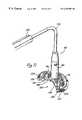
FIG. 1 is a perspective exploded view of a flexible suture guide mounted on a rigid holder assembly in accordance with an embodiment of the invention
FIG. 1A is a top view in partial cross-section of a length of a flexible suture guide in accordance with the present invention.
FIG. 1B is a top view in partial cross-section of the flexible suture guide of the present invention sutured into a ring configuration.
FIG. 2 is an exploded view of the guide mount portion and lower part of the handle portion of the holder assembly of FIG. 1 without the suture guide.
FIG. 3 is a perspective view of a flexible suture guide of the present invention mounted on the assembled guide mount and lower handle portions seen in FIG.2.
FIG. 4 is a cross-sectional view of the assembled guide mount and lower handle portions of FIG. 3 alongline 4—4.
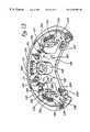
FIG. 5 is a top view of the guide mount seen in FIG. 3 with a flexible suture guide tautly secured thereto.
FIG. 6 is a perspective view of a guide mount in accordance with another embodiment of the invention.
FIG. 7 is a cross-sectional view of a suture guide having a lenticular cross-sectional shape in accordance with another embodiment of the invention.
FIG. 8 is a side perspective sectional view of a handle assembly in accordance with another embodiment of the invention.
FIG. 9 is a bottom view of the handle extension of FIG.8.
FIG. 10 is a top view of the housing of FIG.8.
FIG. 11 is a perspective view of a suture guide holder in accordance with another embodiment of the invention.
FIG. 12 is an exploded view of the guide mount portion and lower handle portion of the suture guide holder of FIG.11.
FIG. 13 is a top view of the guide mount portion of the suture guide holder of FIG.11.
FIG. 14 is a perspective view of a linear suture guide holder in accordance with another embodiment of the invention.
FIG. 15 is a perspective view of the suture guide holder of FIG. 14 with a suture guide attached.
FIG. 16 is a perspective view of a circular suture guide holder in accordance with another embodiment of the invention.
FIG. 17 is a perspective view of the suture guide holder of FIG. 16 with a suture guide attached.
FIG. 18 is a cross-sectional view of the suture guide and holder of FIG. 17 taken alongline 18—18.
The present invention overcomes the above discussed disadvantages by providing an assembly for holding a substantially flexible suture guide in a substantially taut position for placing a suture line having a predetermined dimension. When attached to the holder assembly, the flexible suture guide assumes a shape or geometry, such as a circumference, that conforms to the shape or geometry of that portion of the body organ or vessel that is being sutured. The holder assembly can be formed to hold the suture guide in any desired shape, whether straight, curvilinear, or a combination of the two and the suture guide can be either biodegradable or permanently implantable. Thus the surgeon undertaking reconstructive surgery is aided in achieving a suture line of any desired shape, geometry and/or dimension.
The assembly includes a holder portion having a surface against which the suture guide is positioned and held tautly in a fixed shape, geometry and/or dimension. More particularly, the holder assembly includes a body having an outwardly facing surface, generally flat, against which the suture guide is tautly positioned so that the suture guide assumes the shape, geometry and/or dimension desired for the suture line. Preferably, this surface is formed with at least one depression for receiving a portion of the suture guide. The assembly further includes a detachable handle and a mechanism for releasably binding the suture guide to the surface.
The flexible suture guide used with the assembly of the invention comprises a generally elongated flexible body element having an internal flexible rib encased within a biocompatible covering, such as a woven cloth material. The suture guide can be formed of either biodegradable or non-biodegradable materials depending upon whether its purpose is to serve as a permanent support to prevent tearing out of the sutures placed through it or whether the suture-supporting function is to be a temporary one. In addition to its function as a post-surgical support for sutures, during surgery when used in combination with the holder disclosed herein, the suture guide serves as a rigid support and template by which the surgeon controls the length of the finished suture line. For instance, if the task is to suture together two ends of a bowel from which a section has been removed, the combination of suture guide and holder assure that the circumference of the surgical jointure is substantially similar to the circumference of the nearby regions of the colon, rather than smaller or larger.
Therefore, the holder device is designed to lend a temporary rigidity or tautness to the suture guide while lending to it a shape selected to facilitate the suturing task. For instance, when the task is to place a line of sutures around the circumference of a curvilinear surface, the holder is designed to fit around at least a portion of the circumference while holding the suture guide against the said circumference to aid the surgeon in making a surgical jointure that does not distort the said circumference.
In use, the suture guide is releasably retained against the outwardly facing body surface by a means for releasable attachment, for example one or more threads, pieces of Velcro™, and the like, placed so that the suture guide lies along and temporarily substantially assumes the shape of the body. The means for attachment may also be a biodegradable adhesive having the capacity to firmly attach the suture guide to the holder body for sufficient time to complete the surgery, but having the capacity to dissolve or be dissolved once the suture line has been placed. In one embodiment, the thread attaches the suture guide to the body surface at least at two points, for example at its extreme ends, by passing at least partially through the suture guide and about the body, i.e., by means of an in and out stitch or stitches.
The means for releasable attachment of the suture guide to the body must be such that the suture guide can be released from the body once the suture line has been placed by the surgeon without disturbing the sutures sufficiently to cause dislocation or tearing of the sutures through the tissue. For example, if the means for releasable attachment is one or more threads, a portion of the thread(s) affixing the suture guide to the body can be positioned to be cut by scissors, or the like, to freely release the suture guide from the body. When the thread or threads are cut or otherwise ruptured, the suture guide is freely released from the body.
The present invention is directed to a holder assembly for holding a substantially flexible, implantable suture guide in a substantially taut position for suturing along a suture line having a desired shape or dimension, such as the desired circumference to which an enlarged heart valve annulus is to be reduced by the formation of pleats about the base of the valve annulus. The suture guide of the invention is formed from a freely flexible rib encased within a woven cloth covering. In use, the flexible suture guide of the invention is held taut by the holder assembly and in a configuration determined by the shape of the holder assembly while the surgeon uses the support provided by the taut suture guide to evenly place the sutures and to draw the tissue by means of the sutures passed through the suture guide into a suture line having a shape substantially similar to that of the suture guide and holder. For example, for use in annuloplasty, the holder assembly can be C-shaped so that the suture guide temporarily affixed thereto assumes a C-shaped configuration. The suture guide can then be sutured to the base of a heart valve annulus so as to restrict the circumference of a dilated and/or deformed valve annulus to a more normal one. When the suture guide is released from the holder, it will assume any shape that that portion of the body organ or vessel assumes in accordance with the dynamic function of the organ or vessel.
Generally the guide mount assembly includes a guide support formed with a shape similar to that of the desired suture line, as in the above example wherein the holder assembly is in the general shape of the valve annulus about which the suture guide is to be surgically placed to assist in holding pleats in the walls of the annulus. The suture guide is mounted along at least a portion of this guide support, for example along a straight or a curved portion.
The holder assembly allows the surgeon to properly position the suture guide while the suture guide is used to draw the sutures and associated tissue into the desired configuration during the suturing process. The freely flexible suture guide is given temporary rigidity during surgery by the detachable holder assembly, thus lending precision to the surgeon in controlling the placement and location of the stitches in the suture line. In an annuloplasty, for example, the potential for forming multiple plications as the circumference of the valve annulus is adjusted is thus greatly reduced.
Referring now to FIG. 1A, thesuture guide 10 is an elongate, flexible member of a predetermined dimension. Due to its flexibility, the length ofsuture guide 10 can be manipulated to assume any desired shape, ie., circular, C-shaped, straight, curvilinear or a combination of curvilinear and straight segments. In FIG. 1B,suture guide 10 is shown as shaped into a ring by suturing the two ends together with sutures11. As shown in FIG. 1A,suture guide 10 comprises a substantially flexibleinner rib 14 encased within covering16.
FIG. 1 shows an exploded view of one embodiment of a holder assembly to which a suture guide is mounted, as seen generally at12 and10 respectively. Theholder assembly 12 includes aguide mount assembly 18 and handleassembly 40 comprising ahandle 42 andhousing 44.
FIGS. 2 through 5 illustrate in greater detail theguide mount assembly 18 and how thesuture guide 10 is mounted thereon.Guide mount assembly 18 includes aguide support 20. For illustrative purposes, thesuture guide assembly 18 here shown is one intended for use in plication of a distended heart valve annulus. Therefore facing edge ofguide support 20 is generally C-shaped or annular, having a shape and circumferential dimension similar to that the surgeon desires to achieve in the human heart annulus by means of annuloplasty surgery. More particularly,support 20 is generally lenticular, having a C-shapedportion 28, with its ends connected by astraight side 30.
Thesuture guide 10 is fitted into a groove ortrough 32 located about the curved C-shapedportion 28 of theguide support 20Trough 32 is dimensioned to receive a portion of thesuture guide 10, as best seen in FIG.4. The positioning of thesuture guide 10 within thetrough 32 conformsguide 10 to the shape of theguide support 20 while exposing a substantial portion of the covering16 outside of thetrough 32 to allow the surgeon to pass a suture therethrough.
In the embodiment shown in FIGS. 2-5, theguide mount assembly 18 also includes acentral support hub 22 to which theguide support 20 is attached by a multiplicity of integrally formed spokes, preferably three, one of which is seen at24. The arrangement ofmount assembly 18 including, in this instance, acurved guide support 20 withhub 22 andspokes 24, allows the surgeon to visually observe the heart valve during the suturing process.Central support hub 22 is formed with anannular groove 36. Thisgroove 36 is formed proximate thatend 34 ofhub 22opposite guide support 20, and defines apost member 38. That portion ofhub 22 remaining on the side of thegroove 36 opposite theguide support 20, andhub end 34, includes an inwardly tapering peripheral surface, as seen generally at35. Thehub 22 also includes anopen bore 37 through which is fitted acylindrical plug 39. Theplug 39 is dimensioned to extend out from both sides of thebore 37. The purpose of taperedsurface 35, and theplug 39 will be described hereinafter.
As is further seen in FIG. 1, thehandle assembly 40 includes anelongated handle 42 havingend 54 mounted tohousing 44. Whilehousing 44 may be integrally formed at theend 54 of thepost 42, preferably end54 is formed with outwardly facing threads that threadably mate with threads formed along a surface of anopening 59 formed in the top of thehousing 44. The opposite end ofpost 42 is formed with an external etchedsurface 52 to assist the surgeon in grippingpost 42. In another embodiment, end54 ofpost 42 andopening 59 ofhousing 44 can be formed so thatend 54 can be press fit intoopening 59.
Handleassembly 40 is coupled to theguide mount assembly 18 by insertingend 34 of thehub 22 into thecavity 46, with one of the outwardly extending ends of theplug 39 passing through a respective one of the J-shapednotches surface 35 of thehub 22 engages the inwardly tapering surface of thewall 60. This causes a slight compression of thehub end 34, resulting in a spring force. The spring force acts to restrain the movement of the outwardly extending ends of theplug 39 through the larger legs of the J-shapednotches plug 39 through the larger legs of J-shapednotches handle 40 passing the outward ends ofplug 39 across thelandings 50 and into the smaller leg of the J-shapednotches
The spring force established by the slight compression of thehub end 34 maintains the coupling betweenhousing 44 and guidemount assembly 18. Thehandle 40 is decoupled from theguide mount assembly 18 by reversing the described procedure.
One embodiment of the means for releasably attachingsuture guide 10 to guidesupport 20 ofguide mount assembly 18 is seen in FIG.5.Guide support 20 is formed with twoapertures guide support 20 and communicating withgroove 32. The exact positioning ofapertures apertures guide support 20, at a location proximate two of thespokes 24.
Oneend 71 of a cord orsuture thread 70 is passed through one of the apertures, as illustratedhole 66, and tied off onguide support 20. Theother end 73 ofsuture 70 is passed through the body of suture guide10 from one end to the other. Thisend 73 is then passed first throughhole 68 and then through and tied off athole 66. Aftersuture guide 10 is sutured into position during surgery, i.e., about the valve annulus, that portion of thesuture 70 betweenapertures Suture 70 passes out ofsuture guide 10 by withdrawing thehandle assembly 12.
In accordance with another embodiment (not shown), thefirst end 71 is tied off athole 66, with thesecond end 73 passed first through one end of thesuture guide 10, and then brought back across and passed through the other end ofsuture guide 10, throughhole 68 and again tied off athole 66. Removal ofsuture 70 is accomplished by snipping the suture in two at any point between the two holes and withdrawing it.
An alternative embodiment of theguide mount assembly 80 as seen in FIG. 6 includes aguide support 82 having an open C-shapedside 84 but no straight side joining the ends of the C. Except for the stated difference in shape of theguide support 82, guidemount assembly 80 in FIG. 6 includes elements similar to those described for the suture guide of FIG. 5 (as is indicated by the prime of the previously provided element number), and will be described in no further detail herein. In this embodiment ofguide mount assembly 80, the means for releasably attaching the suture guide to the guide support is a suture (not shown) positioned by tying off as described above across an open space betweenholes 68′ and66′ (not shown).
In a preferred embodiment of the invention, thehandle assembly 40 is tethered to theguide mount assembly 18. As seen in FIG. 1, this tethering is performed by connecting one end of a lanyard, seen generally at100, to thehandle assembly 40 and the other end of thelanyard 100 to theguide support 20, for instance to one ofspokes 24.Lanyard 100 allows a surgeon to detach thehandle assembly 40 from theguide support 20 during the suturing procedure to get a clearer view of the surgical site. By tetheringhandle 40 to theguide mount assembly 18, the risk of the surgeon leaving theguide support 20 in the patient after completion of the surgical procedure is greatly reduced.Lanyard 100 also allows the surgeon to easily remove theguide support 20 after the handle has been detached.
In a still further preferred embodiment, ahandle assembly 40 is modified to house a spool of suture or string that acts like a tether for the guide mount assembly. The tether is attached at opposite ends to the handle assembly and the guide mount assembly respectively and automatically spools out of the handle assembly when the handle is disconnected from the guide mount assembly.
This preferred embodiment is better seen in the several FIGS. 8 through 10. The lower portion of a handle assembly in accordance with this embodiment is seen in FIG. 8 at90. Handleassembly 90 includes ahousing 92, ahandle extension 94, and ahandle post 96.
The main distinction to the previously described embodiment is that thehandle assembly 90 is formed to carry a spool of suture, seen generally at106. Thissuture spool 106 is housed in abore 112 formed in thehandle extension 94. Handleextension 94 andhousing 92 are formed to releasably fit together. Handleextension 94 andhousing 92 includemating collars Collar 108 is formed with agroove 114 that receives atongue 116 extending upward fromcollar 110.Tongue 116 is formed with acentral aperture 122, and two opposing cut-aways aperture 122.
Each of thecollars collar 108 align with apertures130-133 ofcollar 110 when thehandle extension 94 andhousing 92 are fitted together.
Handleextension 94 andhousing 92 are fitted together by placing thetongue 116 into thegroove 114. Sutures are run through aligned apertures to hold thehandle extension 94 andhousing 92 together. For example, onesuture 134 is passed throughapertures handle extension 94 andapertures housing 92, while asecond suture 136 is passed throughapertures handle extension 94 andapertures housing 92.
Thehandle assembly 90 of this embodiment is coupled to theguide mount assembly 18 as stated above. Thehandle post 96 is removed from thehousing 92 by cutting thesutures handle extension 94 away from thehousing 92. Pulling away thehandle post 96 unravels thesuture spool 106. After the suture guide is sutured into position along the suture line, i.e., about a heart valve annulus, the suture(s) holding the guide mount assembly to the suture guide is cut. The guide mount assembly is then removed by pulling on thehandle post 96.
In an other embodiment of the invention, shown in FIGS. 11-13,handle assembly 140 is also modified to house a spool of suture or string that acts like a tether for theguide mount assembly 142. Referring to FIG. 11,handle assembly 140, includeshousing 144, handlepost 146, and anenlarged handle portion 148. Handlepost 146 is preferably made of a malleable metal or other material that allows the surgeon to bend the handle to the desired angle while using the suture guide holder assembly. Theenlarged handle portion 148 allows the surgeon to grip the handle more easily and also makes it easier for the surgeon to maneuver the suture guide holder into the surgery site.Housing 144 is releasably attached to guidemount 150 as will be described in more detail with reference to FIG.12.Suture guide 152 is releasably attached to guidemount 150 by threads or sutures (not shown) in a manner which will be described with reference to FIG.13.
Referring to FIG. 12,housing 144 includes bore154 for receivinghandle post 146. The end ofhandle post 146 may be held inbore 154 by a press fit or friction fit, by welding, or by providing the respective members with interlocking threaded surfaces.Housing 144 also includes a pair of opposingslots 156 for receivingdog ears 158 of thesuture spool 160.Suture spool 160 includes a length of suture orthread 162 wound into a cylindrical configuration alongspindle post 164. One end of thesuture 162 is tied to an aperture (not shown) inupper end 166 ofsuture spool 160. The other end ofsuture 162 is affixed tohub 168 ofguide mount 150. Specifically, suture162 passes down throughaperture 170, up throughaperture 172, and is tied off ataperture 172. The lower end ofspindle post 164 has a pair of opposing notches174 formed therein which are sized to be received bybore 176 ofhub 168.Spindle post 164, therefore, is press fit or friction fit intobore 176.
Once the suture guide and guide mount assembly has been placed at the surgery site, the surgeon can remove the handle if desired by cutting sutures orthreads shallow groove 195 formed therein through which the suture passes and adeeper groove 197 formed in the platform perpendicular to the shallow groove through which scissors or other cutting tools can be inserted to clip or cut the suture at that location. When the sutures are cut and the handle is removed,spool 160 remains withinhousing 144 andsuture 162 remains attached tohub 168. As the handle is pulled away from the guide mount, the suture or thread spools offspindle post 164 thereby providing a tether for removal of the guide mount after the suture guide has been detached from the guide mount and the surgery has been completed.
Referring to FIG. 13,suture guide 152 is releasably attached to guidemount 150 by sutures orthreads Suture 198 is tied off ataperture 204 and then passes through one end of the suture guide and up throughaperture 206 over cuttingguide 208 down throughaperture 206 again, throughsuture guide 152, throughaperture 209, then up throughaperture 210 where the other end ofsuture 198 is tied off.Suture 200 is at one end tied off throughaperture 210 and then passes under theguide mount 150 throughaperture 211, throughsuture guide 152 and up throughaperture 212, across cuttingguide 214 and back down throughaperture 212. Suture200 then passes throughsuture guide 152 again, throughaperture 215 and up throughaperture 216 where it is tied off. Finally,suture 202 is tied off at one end ataperture 216 and passes undersuture guide 150 throughaperture 217, throughsuture guide 152, up throughaperture 218, across cuttingguide 220, down throughaperture 218 again where it passes throughsuture guide 152 and up throughaperture 222 where it is tied off.
Referring to FIG. 13, cutting guides208,214 and220 consist of a raised platform with ashallow groove 228 formed therein through which the suture passes and adeeper groove 230 formed in the platform perpendicular to the shallow groove through which a cutting tool may pass in order to cut the suture at the location lying over the deeper groove. The deeper groove is closed at one end by astop 232 so that the tip of the cutting tool or scissors cannot pass beyond that point. This stop prevents the cutting tool from dipping down into theopen space 234 between the spokes ofguide mount 150 and accidentally cutting the tissue of the patient.
When the surgeon is ready to release the suture guide from thesuture guide mount 150 he merely snips thesutures guide mount 150 since they are tied off on the guide mount.
Referring to FIGS. 14 through 18, there are shown two additional embodiments of suture guide holders for holding a suture guide. FIGS. 14 and 15 illustrate a linear suture guide holder for placing a linear suture guide. FIGS. 16,17 and18 illustrate a circular or ring-shaped suture guide holder for placing a circular suture guide.
Referring to FIG. 14, the linear suture guide holder has adetachable handle 240 of the type shown in FIG.2 and linear-shapedguide mount 242. However, the handle embodiment with the tether illustrated in FIGS. 8 and 12 could also be used.Guide mount 242 has a linear groove ortrough 244 into whichsuture guide 246 is fitted as shown in FIG.15. Apertures248 formed inguide mount 242 are used to suture the suture guide to the guide mount as shown in FIG.15.Guide mount 242 also includes cutting guides252 and254 at each end of the guide mount.
Referring to FIG. 16, there is shown a circular suture guide holder which would be useful for suturing two blood vessels or other vessels, such as intestines, together. It would also be useful for bowel and bronchial resection. The suture guide holder has ahandle 260 which in this embodiment is not shown to be detachable. However, any of the various handle embodiments illustrated previously could be utilized, including the tethering concepts. Thesuture guide mount 258 is ring shaped with a groove ortrough 260 formed on the interior cylindrical surface of the ring. The groove ortrough 260 is shaped to receive acircular suture guide 261 as shown in FIG.17.Suture guide mount 258 has a plurality ofapertures 262 evenly spaced about its circumference for use in suturing thesuture guide 261 to the suture guide holder as shown in FIG.17.Suture 264 is threaded through the apertures and through the suture ring in a manner similar to that described with reference to FIGS. 14 and 15 and will not be further be described in connection with this embodiment. Suture264 can be clipped at two locations such as at266 and268 in order release the suture guide from the suture guide holder. Alternatively, cutting guides can be provided as shown in the embodiments previously described and illustrated.
FIG. 18 shows a cross section of the suture guide holder with the suture guide attached thereto taken alongline 18—18 of FIG.17. FIG. 18 illustrates howgroove 260 engagessuture guide 261 and depictsrib 263 and theouter covering 265 of the suture guide.
Various shaped suture guide holders, C-shaped, linear and circular, have been described and illustrated in the figures, however, in accordance with the present invention, the suture guide holder can be constructed in any desired shape depending on the surgical procedure involved. For example, the suture guide holder could be curvilinear for stomach reduction surgery or for certain cosmetic surgeries when it is necessary to place a suture line along an eyelid or an ear.
While the preferred embodiments have been described, various modifications and substitutions may be made thereto without departing from the scope of the invention. Accordingly, it is to be understood that the invention has been described by way of illustration and not limitation.
Claims (55)
1. A holder in combination with an annuloplasty ring, comprising:
an annuloplasty ring;
a rigid body defining at least a partial circumferential edge about which the annuloplasty ring may be fitted, the body having a visibility window defined within the circumferential edge;
a plurality of cutting guides formed in the body adjacent the circumferential edge; and
a plurality of sutures tautly attaching the annuloplasty ring about the circumferential edge, both ends of each suture being secured to the rigid body with a middle portion threaded through the annuloplasty ring.
2. The combination of claim1, wherein the plurality of cutting guides are evenly spaced about the rigid body circumferential edge so that the annuloplasty ring is tautly attached about the circumferential edge in a uniform manner.
3. The combination of claim1, wherein the rigid body is generally formed in a plane, and the cutting guides extend generally normal to the plane.
4. The combination of claim3, wherein the cutting guides each comprises a raised platform having a first groove formed therein across which one of the sutures passes.
5. The combination of claim4, wherein the cutting guides each further comprises a second groove extending generally perpendicular to the first groove.
6. The combination of claim5, wherein the second groove of each cutting guide is deeper than the first groove.
7. The combination of claim1, further including apertures formed in the circumferential edge and disposed so that the sutures extend generally from the rigid body through an inner circumference of the annuloplasty ring so that the outer circumference of the annuloplasty ring is unobstructed to aid in implantation.
8. The combination of claim1, wherein the rigid body comprises a planar member extending generally in a plane within the circumferential edge, and wherein the visibility window comprises an opening formed in the planar member.
9. The combination of claim8, wherein there are a plurality of visibility windows formed in the planar member by spokes extending from the circumferential edge to a central location.
10. The combination of claim9, further including a hub joining the spokes at the central location, the hub being adapted to attach to a handle for manipulating the holder.
11. The combination of claim10, further including a handle coupled to the hub and formed to be gripped during the placement of sutures through the annuloplasty ring.
12. The combination of claim11, further including a tether extendibly tethering the handle to the body.
13. The combination of claim12, wherein the tether comprises a spool of a length of filamentous material secured at one end to the body and at an opposite end to the handle.
14. The combination of claim13, wherein the handle includes a spool housing having a cavity for housing the spool.
15. The combination of claim1, wherein the circumferential edge is a groove.
16. The combination of claim1, wherein the circumferential edge is a trough.
17. The combination of claim1, wherein the circumferential edge is a depression.
18. The combination of claim1, wherein the circumferential edge is a channel.
19. The combination of claim1, wherein the circumferential edge is generally flat.
20. A substantially rigid holder in combination with an annuloplasty ring, comprising:
a flexible annuloplasty ring;
a body having an outer edge for holding the flexible annuloplasty ring in a plane around the outer edge;
at least one thread releasably retaining the annuloplasty ring around the outer edge in a taut fashion;
a thread guide on the body spaced from the plane of the annuloplasty ring and including a surface supporting the thread, the thread guide having a cutting guide groove opening at the surface for insertion of a cutting tool therein to cut the thread and thereby release the annuloplasty ring from the holder.
21. The holder of claim20, wherein the thread guide includes a raised platform having the thread supporting surface and the cutting guide groove.
22. The holder of claim20, wherein the thread guide includes a second groove receiving the thread, the second groove being defined by surfaces including the thread supporting surface.
23. The holder of claim22, wherein the cutting guide groove is deeper than the second groove.
24. The holder of claim22, wherein the cutting guide groove and second groove are substantially perpendicular to each other.
25. The holder of claim20, wherein an end of the cutting guide groove is closed to stop movement of the tool in an insertion direction.
26. The holder of claim20, further including:
a plurality of apertures formed in the outer edge;
a plurality of the thread guides formed in the body adjacent the outer edge; and
wherein there are a plurality of the threads passing through the apertures and releasably attaching the annuloplasty ring about the outer edge.
27. The holder of claim26, wherein the apertures are disposed so that the sutures extend generally from the body through an inner circumference of the annuloplasty ring so that the outer circumference of the annuloplasty ring is unobstructed to aid in implantation.
28. The holder of claim26, wherein both ends of each thread are secured to the rigid body with a middle portion threaded through the annuloplasty ring.
29. The holder of claim20, further including a ring mounting surface, the annuloplasty ring being tautly positioned against the ring mounting surface by the thread.
30. The holder of claim29, wherein the ring mounting surface comprises an outwardly facing channel into which the annuloplasty ring is at least partially fitted.
31. The holder of claim30, wherein the outwardly facing channel comprises a groove against which the annuloplasty ring is releasably retained by the thread, and wherein the thread is affixed at both ends to the body with a first portion passing through the annuloplasty ring and a second portion passing across the thread guide, the thread being subdivided into two pieces when a cutting tool is inserted in the thread guide, each piece of the thread remaining affixed at one end to the body, with a free portion being pulled from within the annuloplasty ring by displacing the holder away from the annuloplasty ring, thereby releasing the ring from the groove.
32. The holder of claim20, further including a handle coupled to the body and formed to be gripped during the placement of sutures through the annuloplasty ring.
33. The holder of claim32, wherein a second thread releasably couples the body to the handle.
34. The holder of claim33, including a member positioned between the handle and the body and having a handle release groove accessible by a cutting tool to enable the tool to cut the second thread and un-couple the handle from the body.
35. The holder of claim34, wherein the member includes a raised platform on the body, the platform including the handle release groove.
36. The holder of claim32, further including a tether extendibly tethering the handle to the body.
37. The holder of claim36, wherein the tether comprises a spool of a length of filamentous material secured at one end to the body and at an opposite end to the handle.
38. The holder of claim37, wherein the handle includes a spool housing having a cavity for housing the spool.
39. The holder of claim38, wherein the spool housing includes first and second opposed slots for receiving dog ears provided on the spool.
40. The combination of claim20, wherein the outer edge is a groove.
41. The combination of claim20, wherein the outer edge is a trough.
42. The combination of claim20, wherein the outer edge is a depression.
43. The combination of claim20, wherein the outer edge is a channel.
44. The combination of claim20, wherein the outer edge is generally flat.
45. A holder in combination with an annuloplasty ring, comprising:
an annuloplasty ring;
a body having an outer circumferential edge shaped to match the shape of a healthy anatomical heart valve annulus;
a plurality of apertures in the body spaced around the circumferential edge;
a plurality of cutting guides spaced around the circumferential edge; and
a plurality of sutures securing the annuloplasty ring to the circumferential edge of the body, each suture being secured at both ends to the body and being threaded therebetween through a first aperture, through the annuloplasty ring, through a second aperture, across one of the cutting guides, through a third aperture, again through the annuloplasty ring, and through a fourth aperture.
46. The holder of claim45, wherein the plurality of cutting guides are evenly spaced about the rigid body circumferential edge so that the annuloplasty ring is tautly attached about the circumferential edge in a uniform manner.
47. The holder of claim45, further including a handle coupled to the body and formed to be gripped during the placement of sutures through the annuloplasty ring.
48. The holder of claim47, further including a tether extendibly tethering the handle to the body.
49. The holder of claim48, wherein the tether comprises a spool of a length of filamentous material secured at one end to the body and at an opposite end to the handle.
50. The holder of claim49, wherein the handle includes a spool housing having a cavity for housing the spool.
51. The combination of claim45, wherein the circumferential edge is a groove.
52. The combination of claim45, wherein the circumferential edge is a trough.
53. The combination of claim45, wherein the circumferential edge is a depression.
54. The combination of claim45, wherein the circumferential edge is a channel.
55. The combination of claim45, wherein the circumferential edge is generally flat.
Applications Claiming Priority (8)
| Application Number | Priority Date | Filing Date | Title |
|---|---|---|---|
| US38790989A | 1989-07-31 | 1989-07-31 | |
| US07/444,189US5041130A (en) | 1989-07-31 | 1989-11-30 | Flexible annuloplasty ring and holder |
| US73992591A | 1991-08-02 | 1991-08-02 | |
| US08/004,214US5290300A (en) | 1989-07-31 | 1993-01-13 | Flexible suture guide and holder |
| US08/190,755US5496336A (en) | 1989-07-31 | 1994-02-02 | Flexible suture guide and holder |
| US08/474,048US5683402A (en) | 1989-07-31 | 1995-06-07 | Flexible suture guide and holder |
| US90265497A | 1997-07-30 | 1997-07-30 | |
| US8594498A | 1998-05-27 | 1998-05-27 |
Publications (1)
| Publication Number | Publication Date |
|---|---|
| US6283993B1true US6283993B1 (en) | 2001-09-04 |
Family
ID=46247072
Family Applications (7)
| Application Number | Title | Priority Date | Filing Date |
|---|---|---|---|
| US08/004,214Expired - LifetimeUS5290300A (en) | 1989-07-31 | 1993-01-13 | Flexible suture guide and holder |
| US08/190,755Expired - LifetimeUS5496336A (en) | 1989-07-31 | 1994-02-02 | Flexible suture guide and holder |
| US08/474,048Expired - LifetimeUS5683402A (en) | 1989-07-31 | 1995-06-07 | Flexible suture guide and holder |
| US09/085,944Expired - LifetimeUS6283993B1 (en) | 1989-07-31 | 1998-05-27 | Annuloplasty ring delivery system |
| US09/800,074Expired - Fee RelatedUS6558416B2 (en) | 1989-07-31 | 2001-03-06 | Annuloplasty ring delivery method |
| US10/410,458Expired - Fee RelatedUS6802860B2 (en) | 1989-07-31 | 2003-04-08 | Annuloplasty ring delivery system |
| US10/924,424AbandonedUS20050027352A1 (en) | 1989-07-31 | 2004-08-24 | Annuloplasty ring delivery system and method |
Family Applications Before (3)
| Application Number | Title | Priority Date | Filing Date |
|---|---|---|---|
| US08/004,214Expired - LifetimeUS5290300A (en) | 1989-07-31 | 1993-01-13 | Flexible suture guide and holder |
| US08/190,755Expired - LifetimeUS5496336A (en) | 1989-07-31 | 1994-02-02 | Flexible suture guide and holder |
| US08/474,048Expired - LifetimeUS5683402A (en) | 1989-07-31 | 1995-06-07 | Flexible suture guide and holder |
Family Applications After (3)
| Application Number | Title | Priority Date | Filing Date |
|---|---|---|---|
| US09/800,074Expired - Fee RelatedUS6558416B2 (en) | 1989-07-31 | 2001-03-06 | Annuloplasty ring delivery method |
| US10/410,458Expired - Fee RelatedUS6802860B2 (en) | 1989-07-31 | 2003-04-08 | Annuloplasty ring delivery system |
| US10/924,424AbandonedUS20050027352A1 (en) | 1989-07-31 | 2004-08-24 | Annuloplasty ring delivery system and method |
Country Status (1)
| Country | Link |
|---|---|
| US (7) | US5290300A (en) |
Cited By (100)
| Publication number | Priority date | Publication date | Assignee | Title |
|---|---|---|---|---|
| US6425902B1 (en)* | 2001-05-04 | 2002-07-30 | Cardiomend Llc | Surgical instrument for heart valve reconstruction |
| US20020129820A1 (en)* | 2001-03-15 | 2002-09-19 | Medtronic, Inc | Annuloplasty band and method |
| US6514194B2 (en) | 1997-01-02 | 2003-02-04 | Myocor, Inc. | Heart wall tension reduction apparatus and method |
| US20030036795A1 (en)* | 1990-05-18 | 2003-02-20 | Andersen Henning Rud | Valve prosthesis for implantation in the body and a catheter for implanting such valve prosthesis |
| US6537198B1 (en) | 2000-03-21 | 2003-03-25 | Myocor, Inc. | Splint assembly for improving cardiac function in hearts, and method for implanting the splint assembly |
| US20030074012A1 (en)* | 2000-10-10 | 2003-04-17 | Coalescent Surgical, Inc. | Minimally invasive annuloplasty procedure and apparatus |
| US6616684B1 (en) | 2000-10-06 | 2003-09-09 | Myocor, Inc. | Endovascular splinting devices and methods |
| US20030176917A1 (en)* | 2002-03-18 | 2003-09-18 | Medtronic, Inc. | Flexible annuloplasty prosthesis and holder |
| US6626899B2 (en) | 1999-06-25 | 2003-09-30 | Nidus Medical, Llc | Apparatus and methods for treating tissue |
| WO2003079937A2 (en) | 2002-03-18 | 2003-10-02 | Medtronic, Inc. | Flexible annuloplasty prosthesis and holder |
| WO2003105670A2 (en) | 2002-01-10 | 2003-12-24 | Guided Delivery Systems, Inc. | Devices and methods for heart valve repair |
| US20040034410A1 (en)* | 2002-08-16 | 2004-02-19 | Holmberg William R. | Annuloplasty ring holder |
| US20040055608A1 (en)* | 1993-02-22 | 2004-03-25 | Ethicon, Inc. | Minimally-invasive devices and methods for treatment of congestive heart failure |
| US6723038B1 (en) | 2000-10-06 | 2004-04-20 | Myocor, Inc. | Methods and devices for improving mitral valve function |
| US6746471B2 (en) | 1998-07-29 | 2004-06-08 | Myocor, Inc. | Transventricular implant tools and devices |
| US6764510B2 (en) | 2002-01-09 | 2004-07-20 | Myocor, Inc. | Devices and methods for heart valve treatment |
| US20040162611A1 (en)* | 2001-08-24 | 2004-08-19 | Salvador Marquez | Method of implanting a self-molding annuloplasty ring |
| US6786924B2 (en) | 2001-03-15 | 2004-09-07 | Medtronic, Inc. | Annuloplasty band and method |
| US6802319B2 (en) | 1993-02-22 | 2004-10-12 | John H. Stevens | Minimally-invasive devices and methods for treatment of congestive heart failure |
| US6808488B2 (en) | 1998-09-21 | 2004-10-26 | Myocor, Inc. | External stress reduction device and method |
| US20050027352A1 (en)* | 1989-07-31 | 2005-02-03 | Cosgrove Delos M. | Annuloplasty ring delivery system and method |
| US6908424B2 (en) | 1998-07-29 | 2005-06-21 | Myocor, Inc. | Stress reduction apparatus and method |
| US20050256568A1 (en)* | 2004-05-14 | 2005-11-17 | St. Jude Medical, Inc. | C-shaped heart valve prostheses |
| US20050256567A1 (en)* | 2004-05-14 | 2005-11-17 | St. Jude Medical, Inc. | Heart valve annuloplasty prosthesis sewing cuffs and methods of making same |
| US20050256569A1 (en)* | 2004-05-14 | 2005-11-17 | St. Jude Medical, Inc. | Flexible, non-planar annuloplasty rings |
| US20050267572A1 (en)* | 2004-05-14 | 2005-12-01 | St. Jude Medical, Inc. | Systems and methods for holding annuloplasty rings |
| US20050278022A1 (en)* | 2004-06-14 | 2005-12-15 | St. Jude Medical, Inc. | Annuloplasty prostheses with improved anchoring structures, and related methods |
| US20060015177A1 (en)* | 2004-07-19 | 2006-01-19 | St. Jude Medical, Inc. | Heart valve support and lid liner system and methods |
| US7112219B2 (en) | 2002-11-12 | 2006-09-26 | Myocor, Inc. | Devices and methods for heart valve treatment |
| US20060217803A1 (en)* | 2005-03-23 | 2006-09-28 | Ingle Aaron S | Apparatus, system, and method for delivering an annuloplasty ring |
| US20060282162A1 (en)* | 2005-06-09 | 2006-12-14 | Nguyen Trong T | Expandable annuloplasty ring and associated ring holder |
| US7189199B2 (en) | 1997-01-02 | 2007-03-13 | Myocor, Inc. | Methods and devices for improving cardiac function in hearts |
| US20070067028A1 (en)* | 2005-09-21 | 2007-03-22 | Genesee Biomedical, Inc. | Annuloplasty ring holder |
| US20070078514A1 (en)* | 2005-09-30 | 2007-04-05 | Ryan Timothy R | Method of implanting an annuloplasty prosthesis |
| US7247134B2 (en) | 2002-11-12 | 2007-07-24 | Myocor, Inc. | Devices and methods for heart valve treatment |
| US20070191939A1 (en)* | 2005-09-30 | 2007-08-16 | Tim Ryan | Flexible annuloplasty prosthesis |
| US20070244551A1 (en)* | 2006-04-14 | 2007-10-18 | Robert Stobie | Holders for prosthetic aortic heart valves |
| US20070299513A1 (en)* | 2006-06-02 | 2007-12-27 | Ryan Timothy R | Annuloplasty ring and method |
| US20070299514A1 (en)* | 2006-06-02 | 2007-12-27 | Colvin Stephen B | Annuloplasty prosthesis with in vivo shape identification and related methods of use |
| US7534204B2 (en) | 2003-09-03 | 2009-05-19 | Guided Delivery Systems, Inc. | Cardiac visualization devices and methods |
| US7547313B2 (en) | 1998-06-03 | 2009-06-16 | Medtronic, Inc. | Tissue connector apparatus and methods |
| US20090192605A1 (en)* | 2008-01-25 | 2009-07-30 | Medtronic, Inc. | Sizer Device Having a Plurality of Anterior-Posterior Ratios |
| US7588582B2 (en) | 2002-06-13 | 2009-09-15 | Guided Delivery Systems Inc. | Methods for remodeling cardiac tissue |
| US7632308B2 (en) | 2005-11-23 | 2009-12-15 | Didier Loulmet | Methods, devices, and kits for treating mitral valve prolapse |
| US7666193B2 (en) | 2002-06-13 | 2010-02-23 | Guided Delivery Sytems, Inc. | Delivery devices and methods for heart valve repair |
| US7722643B2 (en) | 1999-03-01 | 2010-05-25 | Medtronic, Inc. | Tissue connector apparatus and methods |
| US7744611B2 (en) | 2000-10-10 | 2010-06-29 | Medtronic, Inc. | Minimally invasive valve repair procedure and apparatus |
| US7753922B2 (en) | 2003-09-04 | 2010-07-13 | Guided Delivery Systems, Inc. | Devices and methods for cardiac annulus stabilization and treatment |
| US7753924B2 (en) | 2003-09-04 | 2010-07-13 | Guided Delivery Systems, Inc. | Delivery devices and methods for heart valve repair |
| US7753858B2 (en) | 2002-06-13 | 2010-07-13 | Guided Delivery Systems, Inc. | Delivery devices and methods for heart valve repair |
| US7758637B2 (en) | 2003-02-06 | 2010-07-20 | Guided Delivery Systems, Inc. | Delivery devices and methods for heart valve repair |
| US7763040B2 (en) | 1998-06-03 | 2010-07-27 | Medtronic, Inc. | Tissue connector apparatus and methods |
| US20110022063A1 (en)* | 2009-07-22 | 2011-01-27 | Coloplast A/S | Suturing system and assembly |
| US7879047B2 (en) | 2003-12-10 | 2011-02-01 | Medtronic, Inc. | Surgical connection apparatus and methods |
| US7883538B2 (en) | 2002-06-13 | 2011-02-08 | Guided Delivery Systems Inc. | Methods and devices for termination |
| US7883539B2 (en) | 1997-01-02 | 2011-02-08 | Edwards Lifesciences Llc | Heart wall tension reduction apparatus and method |
| US20110046645A1 (en)* | 2009-08-21 | 2011-02-24 | Colophast A/S | Suture assembly and system |
| US7896892B2 (en) | 2000-03-31 | 2011-03-01 | Medtronic, Inc. | Multiple bias surgical fastener |
| US7938840B2 (en) | 1999-04-05 | 2011-05-10 | Medtronic, Inc. | Apparatus and methods for anastomosis |
| US7963973B2 (en) | 1998-06-03 | 2011-06-21 | Medtronic, Inc. | Multiple loop tissue connector apparatus and methods |
| US7976556B2 (en) | 2002-09-12 | 2011-07-12 | Medtronic, Inc. | Anastomosis apparatus and methods |
| US7976539B2 (en) | 2004-03-05 | 2011-07-12 | Hansen Medical, Inc. | System and method for denaturing and fixing collagenous tissue |
| US20110190879A1 (en)* | 2010-02-03 | 2011-08-04 | Edwards Lifesciences Corporation | Devices and Methods for Treating a Heart |
| US8029519B2 (en) | 2003-08-22 | 2011-10-04 | Medtronic, Inc. | Eversion apparatus and methods |
| US8066766B2 (en) | 2002-06-13 | 2011-11-29 | Guided Delivery Systems Inc. | Methods and devices for termination |
| US8092367B2 (en) | 2001-09-07 | 2012-01-10 | Mardil, Inc. | Method for external stabilization of the base of the heart |
| US8105345B2 (en) | 2002-10-04 | 2012-01-31 | Medtronic, Inc. | Anastomosis apparatus and methods |
| US8118822B2 (en) | 1999-03-01 | 2012-02-21 | Medtronic, Inc. | Bridge clip tissue connector apparatus and methods |
| US8177836B2 (en) | 2008-03-10 | 2012-05-15 | Medtronic, Inc. | Apparatus and methods for minimally invasive valve repair |
| US8187323B2 (en) | 1997-12-17 | 2012-05-29 | Edwards Lifesciences, Llc | Valve to myocardium tension members device and method |
| US8211124B2 (en) | 2003-07-25 | 2012-07-03 | Medtronic, Inc. | Sealing clip, delivery systems, and methods |
| US8216304B2 (en) | 2005-03-23 | 2012-07-10 | Edwards Lifesciences Corporation | Annuloplasty ring and holder combination |
| US8287555B2 (en) | 2003-02-06 | 2012-10-16 | Guided Delivery Systems, Inc. | Devices and methods for heart valve repair |
| US8394114B2 (en) | 2003-09-26 | 2013-03-12 | Medtronic, Inc. | Surgical connection apparatus and methods |
| US8465500B2 (en) | 2005-01-21 | 2013-06-18 | Mayo Foundation For Medical Education And Research | Thorascopic heart valve repair method and apparatus |
| US8529583B1 (en) | 1999-09-03 | 2013-09-10 | Medtronic, Inc. | Surgical clip removal apparatus |
| US8623033B2 (en) | 2011-07-20 | 2014-01-07 | Coloplast A/S | Suture system with capsule eyelet providing multiple suture tissue fixation |
| US8641727B2 (en) | 2002-06-13 | 2014-02-04 | Guided Delivery Systems, Inc. | Devices and methods for heart valve repair |
| US8758393B2 (en) | 2007-10-18 | 2014-06-24 | Neochord, Inc. | Minimally invasive repair of a valve leaflet in a beating heart |
| US8790367B2 (en) | 2008-02-06 | 2014-07-29 | Guided Delivery Systems Inc. | Multi-window guide tunnel |
| US8795298B2 (en) | 2008-10-10 | 2014-08-05 | Guided Delivery Systems Inc. | Tether tensioning devices and related methods |
| US8920493B2 (en) | 2011-09-16 | 2014-12-30 | St. Jude Medical, Cardiology Division, Inc. | Systems and methods for holding annuloplasty rings |
| US9044221B2 (en) | 2010-12-29 | 2015-06-02 | Neochord, Inc. | Exchangeable system for minimally invasive beating heart repair of heart valve leaflets |
| US9616197B2 (en) | 2009-01-20 | 2017-04-11 | Ancora Heart, Inc. | Anchor deployment devices and related methods |
| US9636106B2 (en) | 2008-10-10 | 2017-05-02 | Ancora Heart, Inc. | Termination devices and related methods |
| US9861350B2 (en) | 2010-09-03 | 2018-01-09 | Ancora Heart, Inc. | Devices and methods for anchoring tissue |
| US9949829B2 (en) | 2002-06-13 | 2018-04-24 | Ancora Heart, Inc. | Delivery devices and methods for heart valve repair |
| US10058321B2 (en) | 2015-03-05 | 2018-08-28 | Ancora Heart, Inc. | Devices and methods of visualizing and determining depth of penetration in cardiac tissue |
| US10588620B2 (en) | 2018-03-23 | 2020-03-17 | Neochord, Inc. | Device for suture attachment for minimally invasive heart valve repair |
| US10667914B2 (en) | 2016-11-18 | 2020-06-02 | Ancora Heart, Inc. | Myocardial implant load sharing device and methods to promote LV function |
| US10695178B2 (en) | 2011-06-01 | 2020-06-30 | Neochord, Inc. | Minimally invasive repair of heart valve leaflets |
| US10765517B2 (en) | 2015-10-01 | 2020-09-08 | Neochord, Inc. | Ringless web for repair of heart valves |
| US10966709B2 (en) | 2018-09-07 | 2021-04-06 | Neochord, Inc. | Device for suture attachment for minimally invasive heart valve repair |
| US10980973B2 (en) | 2015-05-12 | 2021-04-20 | Ancora Heart, Inc. | Device and method for releasing catheters from cardiac structures |
| US11173030B2 (en) | 2018-05-09 | 2021-11-16 | Neochord, Inc. | Suture length adjustment for minimally invasive heart valve repair |
| US11253360B2 (en) | 2018-05-09 | 2022-02-22 | Neochord, Inc. | Low profile tissue anchor for minimally invasive heart valve repair |
| US11376126B2 (en) | 2019-04-16 | 2022-07-05 | Neochord, Inc. | Transverse helical cardiac anchor for minimally invasive heart valve repair |
| US11589989B2 (en) | 2017-03-31 | 2023-02-28 | Neochord, Inc. | Minimally invasive heart valve repair in a beating heart |
| US11672524B2 (en) | 2019-07-15 | 2023-06-13 | Ancora Heart, Inc. | Devices and methods for tether cutting |
| US12208007B2 (en) | 2020-01-16 | 2025-01-28 | Neochord, Inc. | Helical cardiac anchors for minimally invasive heart valve repair |
Families Citing this family (274)
| Publication number | Priority date | Publication date | Assignee | Title |
|---|---|---|---|---|
| USD360688S (en) | 1993-02-16 | 1995-07-25 | American Cyanamid Company | Combined proximal end and shaft of a low profile surgical suture knot pusher |
| USD360687S (en) | 1993-02-16 | 1995-07-25 | American Cyanamid Company | Combined proximal end and shaft of a surgical suture slotted knot pusher |
| USD359355S (en) | 1993-02-16 | 1995-06-13 | American Cyanamid Company | Surgical suture knot pusher with hooks |
| US5972030A (en)* | 1993-02-22 | 1999-10-26 | Heartport, Inc. | Less-invasive devices and methods for treatment of cardiac valves |
| FR2708458B1 (en)* | 1993-08-03 | 1995-09-15 | Seguin Jacques | Prosthetic ring for cardiac surgery. |
| US5849005A (en) | 1995-06-07 | 1998-12-15 | Heartport, Inc. | Method and apparatus for minimizing the risk of air embolism when performing a procedure in a patient's thoracic cavity |
| WO1996039942A1 (en) | 1995-06-07 | 1996-12-19 | Heartport, Inc. | Less invasive devices and methods for treatment of cardiac valves |
| CA2227142A1 (en)* | 1995-07-17 | 1997-02-06 | Alfred Edward Wood | A buttress for cardiac valve reconstruction |
| DE69630235T2 (en)* | 1995-12-01 | 2004-08-05 | Medtronic, Inc., Minneapolis | Annuloplasty prosthesis |
| USD386583S (en)* | 1996-01-02 | 1997-11-18 | Acufex Microsurgical, Inc. | Proximal end of a surgical suture slotted knot pusher |
| USD387161S (en)* | 1996-01-02 | 1997-12-02 | Acufex Microsurgical, Inc. | Surgical suture knot pusher with hooks |
| US5855602A (en)* | 1996-09-09 | 1999-01-05 | Shelhigh, Inc. | Heart valve prosthesis |
| US5860992A (en)* | 1996-01-31 | 1999-01-19 | Heartport, Inc. | Endoscopic suturing devices and methods |
| US5843177A (en)* | 1996-05-02 | 1998-12-01 | St. Jude Medical, Inc. | Apparatus for attaching a handle to an annuloplasty ring implantation device |
| US5843178A (en)* | 1996-06-20 | 1998-12-01 | St. Jude Medical, Inc. | Suture guard for annuloplasty ring |
| US5814101A (en)* | 1996-09-25 | 1998-09-29 | St. Jude Medical, Inc. | Holder for heart valve prosthesis |
| US5800531A (en)* | 1996-09-30 | 1998-09-01 | Baxter International Inc. | Bioprosthetic heart valve implantation device |
| US5759189A (en)* | 1997-02-25 | 1998-06-02 | Smith & Nephew Inc. | Knot pusher |
| US5980473A (en)* | 1997-04-08 | 1999-11-09 | Barnes-Jewish Hospital | Surgical apparatus for determining ligament and tendon tension |
| US6077278A (en)* | 1997-09-17 | 2000-06-20 | Mayer; Paul W. | Suture needle holder |
| US5984959A (en)* | 1997-09-19 | 1999-11-16 | United States Surgical | Heart valve replacement tools and procedures |
| US6096074A (en) | 1998-01-27 | 2000-08-01 | United States Surgical | Stapling apparatus and method for heart valve replacement |
| US6001127A (en)* | 1998-03-31 | 1999-12-14 | St. Jude Medical, Inc. | Annuloplasty ring holder |
| US7722667B1 (en) | 1998-04-20 | 2010-05-25 | St. Jude Medical, Inc. | Two piece bioprosthetic heart valve with matching outer frame and inner valve |
| US6019739A (en)* | 1998-06-18 | 2000-02-01 | Baxter International Inc. | Minimally invasive valve annulus sizer |
| US6066160A (en)* | 1998-11-23 | 2000-05-23 | Quickie Llc | Passive knotless suture terminator for use in minimally invasive surgery and to facilitate standard tissue securing |
| US6126007A (en)* | 1998-12-30 | 2000-10-03 | St. Jude Medical, Inc. | Tissue valve holder |
| US6475142B1 (en) | 1999-11-12 | 2002-11-05 | Genzyme Corporation | Curved stabilization arm for use with surgical retractor and tissue stabilization device and methods related thereto |
| US6736845B2 (en)* | 1999-01-26 | 2004-05-18 | Edwards Lifesciences Corporation | Holder for flexible heart valve |
| US20040092964A1 (en)* | 1999-03-04 | 2004-05-13 | Modesitt D. Bruce | Articulating suturing device and method |
| US6406492B1 (en)* | 1999-04-08 | 2002-06-18 | Sulzer Carbomedics Inc. | Annuloplasty ring holder |
| US6309417B1 (en)* | 1999-05-12 | 2001-10-30 | Paul A. Spence | Heart valve and apparatus for replacement thereof |
| US6319280B1 (en) | 1999-08-03 | 2001-11-20 | St. Jude Medical, Inc. | Prosthetic ring holder |
| US6440164B1 (en) | 1999-10-21 | 2002-08-27 | Scimed Life Systems, Inc. | Implantable prosthetic valve |
| CN1806775A (en)* | 2000-01-14 | 2006-07-26 | 维亚科公司 | Tissue annuloplasty band and apparatus and method for fashioning, sizing and implanting the same |
| US6402781B1 (en)* | 2000-01-31 | 2002-06-11 | Mitralife | Percutaneous mitral annuloplasty and cardiac reinforcement |
| US7296577B2 (en)* | 2000-01-31 | 2007-11-20 | Edwards Lifescience Ag | Transluminal mitral annuloplasty with active anchoring |
| US6989028B2 (en) | 2000-01-31 | 2006-01-24 | Edwards Lifesciences Ag | Medical system and method for remodeling an extravascular tissue structure |
| US6409758B2 (en)* | 2000-07-27 | 2002-06-25 | Edwards Lifesciences Corporation | Heart valve holder for constricting the valve commissures and methods of use |
| US6524338B1 (en) | 2000-08-25 | 2003-02-25 | Steven R. Gundry | Method and apparatus for stapling an annuloplasty band in-situ |
| US6716243B1 (en)* | 2000-09-13 | 2004-04-06 | Quickie, Inc. | Concentric passive knotless suture terminator |
| US6602288B1 (en)* | 2000-10-05 | 2003-08-05 | Edwards Lifesciences Corporation | Minimally-invasive annuloplasty repair segment delivery template, system and method of use |
| US6602286B1 (en) | 2000-10-26 | 2003-08-05 | Ernst Peter Strecker | Implantable valve system |
| US7009704B1 (en)* | 2000-10-26 | 2006-03-07 | Kla-Tencor Technologies Corporation | Overlay error detection |
| US6966925B2 (en) | 2000-12-21 | 2005-11-22 | Edwards Lifesciences Corporation | Heart valve holder and method for resisting suture looping |
| USRE46668E1 (en)* | 2000-12-21 | 2018-01-16 | Edwards Lifesciences Corporation | Heart valve holder and method for resisting suture looping |
| US7510576B2 (en)* | 2001-01-30 | 2009-03-31 | Edwards Lifesciences Ag | Transluminal mitral annuloplasty |
| US6810882B2 (en) | 2001-01-30 | 2004-11-02 | Ev3 Santa Rosa, Inc. | Transluminal mitral annuloplasty |
| US7935145B2 (en)* | 2001-05-17 | 2011-05-03 | Edwards Lifesciences Corporation | Annuloplasty ring for ischemic mitral valve insuffuciency |
| ITMI20011012A1 (en) | 2001-05-17 | 2002-11-17 | Ottavio Alfieri | ANNULAR PROSTHESIS FOR MITRAL VALVE |
| WO2002098506A1 (en)* | 2001-06-01 | 2002-12-12 | St. Croix Medical, Inc. | Flexible transducer suports |
| US6749630B2 (en) | 2001-08-28 | 2004-06-15 | Edwards Lifesciences Corporation | Tricuspid ring and template |
| US6908482B2 (en)* | 2001-08-28 | 2005-06-21 | Edwards Lifesciences Corporation | Three-dimensional annuloplasty ring and template |
| US7367991B2 (en)* | 2001-08-28 | 2008-05-06 | Edwards Lifesciences Corporation | Conformal tricuspid annuloplasty ring and template |
| US6805710B2 (en)* | 2001-11-13 | 2004-10-19 | Edwards Lifesciences Corporation | Mitral valve annuloplasty ring for molding left ventricle geometry |
| EP1450732A1 (en) | 2001-12-04 | 2004-09-01 | Edwards Lifesciences Corporation | Minimally-invasive annuloplasty repair segment delivery template system |
| US20030125715A1 (en)* | 2001-12-28 | 2003-07-03 | Kuehn Stephen T. | Annuloplasty ring holder |
| US6651661B2 (en)* | 2002-03-12 | 2003-11-25 | Adrian A. Matioc | Ergonomic face mask |
| US7007698B2 (en) | 2002-04-03 | 2006-03-07 | Boston Scientific Corporation | Body lumen closure |
| US6752828B2 (en) | 2002-04-03 | 2004-06-22 | Scimed Life Systems, Inc. | Artificial valve |
| US7608103B2 (en)* | 2002-07-08 | 2009-10-27 | Edwards Lifesciences Corporation | Mitral valve annuloplasty ring having a posterior bow |
| AU2003285943B2 (en) | 2002-10-24 | 2008-08-21 | Boston Scientific Limited | Venous valve apparatus and method |
| US6945957B2 (en) | 2002-12-30 | 2005-09-20 | Scimed Life Systems, Inc. | Valve treatment catheter and methods |
| US20040199185A1 (en)* | 2003-02-21 | 2004-10-07 | Rose-Hulman Institute Of Technology | Suturing method and apparatus |
| US7473259B2 (en)* | 2003-06-30 | 2009-01-06 | Depuy Products, Inc. | Implant stabilizing instrument, kit and method |
| US9198786B2 (en) | 2003-09-03 | 2015-12-01 | Bolton Medical, Inc. | Lumen repair device with capture structure |
| US7763063B2 (en) | 2003-09-03 | 2010-07-27 | Bolton Medical, Inc. | Self-aligning stent graft delivery system, kit, and method |
| US20070198078A1 (en) | 2003-09-03 | 2007-08-23 | Bolton Medical, Inc. | Delivery system and method for self-centering a Proximal end of a stent graft |
| US11596537B2 (en) | 2003-09-03 | 2023-03-07 | Bolton Medical, Inc. | Delivery system and method for self-centering a proximal end of a stent graft |
| US8500792B2 (en) | 2003-09-03 | 2013-08-06 | Bolton Medical, Inc. | Dual capture device for stent graft delivery system and method for capturing a stent graft |
| US11259945B2 (en) | 2003-09-03 | 2022-03-01 | Bolton Medical, Inc. | Dual capture device for stent graft delivery system and method for capturing a stent graft |
| US20080264102A1 (en) | 2004-02-23 | 2008-10-30 | Bolton Medical, Inc. | Sheath Capture Device for Stent Graft Delivery System and Method for Operating Same |
| US8292943B2 (en) | 2003-09-03 | 2012-10-23 | Bolton Medical, Inc. | Stent graft with longitudinal support member |
| US8128681B2 (en) | 2003-12-19 | 2012-03-06 | Boston Scientific Scimed, Inc. | Venous valve apparatus, system, and method |
| US7854761B2 (en) | 2003-12-19 | 2010-12-21 | Boston Scientific Scimed, Inc. | Methods for venous valve replacement with a catheter |
| US7441234B2 (en)* | 2004-02-13 | 2008-10-21 | Microsoft Corporation | Correlating trace events |
| US7951196B2 (en) | 2004-04-29 | 2011-05-31 | Edwards Lifesciences Corporation | Annuloplasty ring for mitral valve prolapse |
| US7294148B2 (en)* | 2004-04-29 | 2007-11-13 | Edwards Lifesciences Corporation | Annuloplasty ring for mitral valve prolapse |
| US7377941B2 (en)* | 2004-06-29 | 2008-05-27 | Micardia Corporation | Adjustable cardiac valve implant with selective dimensional adjustment |
| US20080183285A1 (en)* | 2004-06-29 | 2008-07-31 | Micardia Corporation | Adjustable cardiac valve implant with selective dimensional adjustment |
| US7632284B2 (en)* | 2004-07-06 | 2009-12-15 | Tyco Healthcare Group Lp | Instrument kit and method for performing meniscal repair |
| US20060015178A1 (en)* | 2004-07-15 | 2006-01-19 | Shahram Moaddeb | Implants and methods for reshaping heart valves |
| US7566343B2 (en) | 2004-09-02 | 2009-07-28 | Boston Scientific Scimed, Inc. | Cardiac valve, system, and method |
| BRPI0404380C1 (en)* | 2004-10-14 | 2008-07-15 | Malavazi Vedacoes Ind Ltda | housed mechanical seal enhancements for progressive cavity pumps |
| US7854755B2 (en) | 2005-02-01 | 2010-12-21 | Boston Scientific Scimed, Inc. | Vascular catheter, system, and method |
| US20060173490A1 (en) | 2005-02-01 | 2006-08-03 | Boston Scientific Scimed, Inc. | Filter system and method |
| US7878966B2 (en) | 2005-02-04 | 2011-02-01 | Boston Scientific Scimed, Inc. | Ventricular assist and support device |
| US7670368B2 (en) | 2005-02-07 | 2010-03-02 | Boston Scientific Scimed, Inc. | Venous valve apparatus, system, and method |
| US7780722B2 (en) | 2005-02-07 | 2010-08-24 | Boston Scientific Scimed, Inc. | Venous valve apparatus, system, and method |
| US7867274B2 (en) | 2005-02-23 | 2011-01-11 | Boston Scientific Scimed, Inc. | Valve apparatus, system and method |
| CN102247225B (en)* | 2005-02-28 | 2015-07-22 | 梅德坦提亚国际有限公司 | Device for improving the function of heart valve and kit |
| US8608797B2 (en) | 2005-03-17 | 2013-12-17 | Valtech Cardio Ltd. | Mitral valve treatment techniques |
| US7722666B2 (en) | 2005-04-15 | 2010-05-25 | Boston Scientific Scimed, Inc. | Valve apparatus, system and method |
| US20060238019A1 (en)* | 2005-04-21 | 2006-10-26 | Mark Yu | Brakable wheel hub device |
| US8333777B2 (en) | 2005-04-22 | 2012-12-18 | Benvenue Medical, Inc. | Catheter-based tissue remodeling devices and methods |
| US8012198B2 (en) | 2005-06-10 | 2011-09-06 | Boston Scientific Scimed, Inc. | Venous valve, system, and method |
| US8685083B2 (en)* | 2005-06-27 | 2014-04-01 | Edwards Lifesciences Corporation | Apparatus, system, and method for treatment of posterior leaflet prolapse |
| US8951285B2 (en) | 2005-07-05 | 2015-02-10 | Mitralign, Inc. | Tissue anchor, anchoring system and methods of using the same |
| US20070055368A1 (en)* | 2005-09-07 | 2007-03-08 | Richard Rhee | Slotted annuloplasty ring |
| US8128691B2 (en) | 2005-09-07 | 2012-03-06 | Medtentia International Ltd. Oy | Device and method for improving the function of a heart valve |
| US7569071B2 (en) | 2005-09-21 | 2009-08-04 | Boston Scientific Scimed, Inc. | Venous valve, system, and method with sinus pocket |
| US7878970B2 (en) | 2005-09-28 | 2011-02-01 | Boston Scientific Scimed, Inc. | Apparatus and method for suspending a uterus |
| JP5361392B2 (en)* | 2005-12-15 | 2013-12-04 | ジョージア テック リサーチ コーポレイション | System and method enabling heart valve replacement |
| JP2009519784A (en) | 2005-12-15 | 2009-05-21 | ジョージア テック リサーチ コーポレイション | System and method for controlling heart valve dimensions |
| JP5371440B2 (en)* | 2005-12-15 | 2013-12-18 | ジョージア テック リサーチ コーポレイション | Papillary muscle position control device, system and method |
| US20070142907A1 (en)* | 2005-12-16 | 2007-06-21 | Micardia Corporation | Adjustable prosthetic valve implant |
| US9144483B2 (en)* | 2006-01-13 | 2015-09-29 | Boston Scientific Scimed, Inc. | Placing fixation devices |
| US7799038B2 (en) | 2006-01-20 | 2010-09-21 | Boston Scientific Scimed, Inc. | Translumenal apparatus, system, and method |
| CA2644983C (en)* | 2006-03-16 | 2015-09-29 | Boston Scientific Limited | System and method for treating tissue wall prolapse |
| US7536228B2 (en) | 2006-03-24 | 2009-05-19 | Micardia Corporation | Activation device for dynamic ring manipulation |
| US8454683B2 (en)* | 2006-04-12 | 2013-06-04 | Medtronic Vascular, Inc. | Annuloplasty device having a helical anchor and methods for its use |
| EP2029053B1 (en) | 2006-05-15 | 2011-02-23 | Edwards Lifesciences AG | A system for altering the geometry of the heart |
| US20080058924A1 (en)* | 2006-09-01 | 2008-03-06 | Aaron Ingle | Saddle-shaped annuloplasty ring |
| US7879087B2 (en)* | 2006-10-06 | 2011-02-01 | Edwards Lifesciences Corporation | Mitral and tricuspid annuloplasty rings |
| US9943409B2 (en) | 2006-11-14 | 2018-04-17 | The United States Of America, As Represented By The Secretary, Department Of Health And Human Services | Transcatheter coronary sinus mitral valve annuloplasty procedure and coronary artery and myocardial protection device |
| US8211171B2 (en) | 2006-11-14 | 2012-07-03 | The United States Of America, As Represented By The Secretary Of The Department Of Health And Human Services | Transcatheter coronary sinus mitral valve annuloplasty procedure and coronary artery and myocardial protection device |
| ATE514382T1 (en) | 2006-11-30 | 2011-07-15 | Wilson Cook Medical Inc | FABRIC ANCHOR FOR SEAM CLOSURE OF PERFORATIONS |
| US20080228272A1 (en)* | 2006-12-04 | 2008-09-18 | Micardia Corporation | Dynamically adjustable suture and chordae tendinae |
| AU2007330338A1 (en)* | 2006-12-05 | 2008-06-12 | Valtech Cardio, Ltd. | Segmented ring placement |
| US9883943B2 (en) | 2006-12-05 | 2018-02-06 | Valtech Cardio, Ltd. | Implantation of repair devices in the heart |
| US11259924B2 (en) | 2006-12-05 | 2022-03-01 | Valtech Cardio Ltd. | Implantation of repair devices in the heart |
| WO2008091493A1 (en) | 2007-01-08 | 2008-07-31 | California Institute Of Technology | In-situ formation of a valve |
| US7967853B2 (en) | 2007-02-05 | 2011-06-28 | Boston Scientific Scimed, Inc. | Percutaneous valve, system and method |
| CA2677361C (en)* | 2007-02-09 | 2016-04-05 | Edwards Lifesciences Corporation | Progressively sized annuloplasty rings |
| US11660190B2 (en) | 2007-03-13 | 2023-05-30 | Edwards Lifesciences Corporation | Tissue anchors, systems and methods, and devices |
| US8529620B2 (en)* | 2007-05-01 | 2013-09-10 | Ottavio Alfieri | Inwardly-bowed tricuspid annuloplasty ring |
| US9333076B1 (en) | 2007-05-24 | 2016-05-10 | St. Jude Medical, Inc. | Prosthetic heart valve holder apparatus |
| US8740937B2 (en) | 2007-05-31 | 2014-06-03 | Cook Medical Technologies Llc | Suture lock |
| US8828079B2 (en) | 2007-07-26 | 2014-09-09 | Boston Scientific Scimed, Inc. | Circulatory valve, system and method |
| JP5297458B2 (en) | 2007-08-17 | 2013-09-25 | クック メディカル テクノロジーズ エルエルシー | Device for opening and closing a body wall |
| CA2698388C (en) | 2007-09-07 | 2015-11-24 | Edwards Lifesciences Corporation | Active holder for annuloplasty ring delivery |
| US7892276B2 (en) | 2007-12-21 | 2011-02-22 | Boston Scientific Scimed, Inc. | Valve with delayed leaflet deployment |
| US9078728B2 (en)* | 2007-12-28 | 2015-07-14 | Boston Scientific Scimed, Inc. | Devices and methods for delivering female pelvic floor implants |
| US8430807B2 (en) | 2007-12-28 | 2013-04-30 | Boston Scientific Scimed, Inc. | Devices and methods for treating pelvic floor dysfunctions |
| US9282958B2 (en) | 2007-12-28 | 2016-03-15 | Boston Scientific Scimed, Inc. | Devices and method for treating pelvic dysfunctions |
| AU2009204417B2 (en) | 2008-01-03 | 2013-05-09 | Cook Medical Technologies Llc | Medical systems and devices for endoscopically suturing perforations |
| US8382829B1 (en) | 2008-03-10 | 2013-02-26 | Mitralign, Inc. | Method to reduce mitral regurgitation by cinching the commissure of the mitral valve |
| US7972370B2 (en)* | 2008-04-24 | 2011-07-05 | Medtronic Vascular, Inc. | Stent graft system and method of use |
| US8152844B2 (en) | 2008-05-09 | 2012-04-10 | Edwards Lifesciences Corporation | Quick-release annuloplasty ring holder |
| US8123806B1 (en)* | 2008-05-09 | 2012-02-28 | Cayenne Medical, Inc | Method of tensioning a tissue graft having suture bundles using a cleated bar |
| US20090287303A1 (en) | 2008-05-13 | 2009-11-19 | Edwards Lifesciences Corporation | Physiologically harmonized tricuspid annuloplasty ring |
| EP2296744B1 (en) | 2008-06-16 | 2019-07-31 | Valtech Cardio, Ltd. | Annuloplasty devices |
| CN102076281B (en) | 2008-06-30 | 2014-11-05 | 波顿医疗公司 | Systems and methods for abdominal aortic aneurysm |
| US9314335B2 (en) | 2008-09-19 | 2016-04-19 | Edwards Lifesciences Corporation | Prosthetic heart valve configured to receive a percutaneous prosthetic heart valve implantation |
| US8287591B2 (en)* | 2008-09-19 | 2012-10-16 | Edwards Lifesciences Corporation | Transformable annuloplasty ring configured to receive a percutaneous prosthetic heart valve implantation |
| US10517719B2 (en) | 2008-12-22 | 2019-12-31 | Valtech Cardio, Ltd. | Implantation of repair devices in the heart |
| US8911494B2 (en) | 2009-05-04 | 2014-12-16 | Valtech Cardio, Ltd. | Deployment techniques for annuloplasty ring |
| US8715342B2 (en) | 2009-05-07 | 2014-05-06 | Valtech Cardio, Ltd. | Annuloplasty ring with intra-ring anchoring |
| WO2010073246A2 (en) | 2008-12-22 | 2010-07-01 | Valtech Cardio, Ltd. | Adjustable annuloplasty devices and adjustment mechanisms therefor |
| US9011530B2 (en) | 2008-12-22 | 2015-04-21 | Valtech Cardio, Ltd. | Partially-adjustable annuloplasty structure |
| US8241351B2 (en) | 2008-12-22 | 2012-08-14 | Valtech Cardio, Ltd. | Adjustable partial annuloplasty ring and mechanism therefor |
| US20110011917A1 (en)* | 2008-12-31 | 2011-01-20 | Hansen Medical, Inc. | Methods, devices, and kits for treating valve prolapse |
| EP2393452B1 (en)* | 2009-02-06 | 2016-07-20 | St. Jude Medical, Inc. | Robotic heart valve annulus sizer |
| US8784484B2 (en)* | 2009-02-06 | 2014-07-22 | St. Jude Medical, Inc. | Adjustable annuloplasty ring support |
| US8353956B2 (en) | 2009-02-17 | 2013-01-15 | Valtech Cardio, Ltd. | Actively-engageable movement-restriction mechanism for use with an annuloplasty structure |
| EP3284447B1 (en) | 2009-03-13 | 2020-05-20 | Bolton Medical Inc. | System for deploying an endoluminal prosthesis at a surgical site |
| CA2757554A1 (en) | 2009-04-03 | 2010-10-07 | Cook Medical Technologies Llc | Tissue anchors and medical devices for rapid deployment of tissue anchors |
| US20100261662A1 (en)* | 2009-04-09 | 2010-10-14 | Endologix, Inc. | Utilization of mural thrombus for local drug delivery into vascular tissue |
| US9125716B2 (en) | 2009-04-17 | 2015-09-08 | Boston Scientific Scimed, Inc. | Delivery sleeve for pelvic floor implants |
| WO2010122553A1 (en)* | 2009-04-21 | 2010-10-28 | Aspect Magnet Technologies Ltd. | Flexible segmented support structure |
| EP2429374B1 (en) | 2009-05-01 | 2013-09-25 | Cook Medical Technologies LLC | Medical device for suturing perforations |
| US9968452B2 (en) | 2009-05-04 | 2018-05-15 | Valtech Cardio, Ltd. | Annuloplasty ring delivery cathethers |
| WO2010151382A1 (en) | 2009-06-26 | 2010-12-29 | Wilson-Cook Medical Inc. | Linear clamps for anastomosis |
| US9180007B2 (en) | 2009-10-29 | 2015-11-10 | Valtech Cardio, Ltd. | Apparatus and method for guide-wire based advancement of an adjustable implant |
| US9011520B2 (en) | 2009-10-29 | 2015-04-21 | Valtech Cardio, Ltd. | Tissue anchor for annuloplasty device |
| US10098737B2 (en) | 2009-10-29 | 2018-10-16 | Valtech Cardio, Ltd. | Tissue anchor for annuloplasty device |
| US8545525B2 (en) | 2009-11-03 | 2013-10-01 | Cook Medical Technologies Llc | Planar clamps for anastomosis |
| US8734467B2 (en) | 2009-12-02 | 2014-05-27 | Valtech Cardio, Ltd. | Delivery tool for implantation of spool assembly coupled to a helical anchor |
| US8870950B2 (en) | 2009-12-08 | 2014-10-28 | Mitral Tech Ltd. | Rotation-based anchoring of an implant |
| US20110160849A1 (en)* | 2009-12-22 | 2011-06-30 | Edwards Lifesciences Corporation | Bimodal tricuspid annuloplasty ring |
| US8449608B2 (en)* | 2010-01-22 | 2013-05-28 | Edwards Lifesciences Corporation | Tricuspid ring |
| US8603121B2 (en) | 2010-04-14 | 2013-12-10 | Cook Medical Technologies Llc | Systems and methods for creating anastomoses |
| US11653910B2 (en) | 2010-07-21 | 2023-05-23 | Cardiovalve Ltd. | Helical anchor implantation |
| EP2608743B1 (en) | 2010-08-24 | 2018-04-04 | Edwards Lifesciences Corporation | Flexible annuloplasty ring with select control points |
| CA2812007C (en) | 2010-08-31 | 2016-06-21 | Edwards Lifesciences Corporation | Physiologic tricuspid annuloplasty ring |
| US8911348B2 (en) | 2010-09-02 | 2014-12-16 | Boston Scientific Scimed, Inc. | Pelvic implants and methods of implanting the same |
| US9125741B2 (en) | 2010-09-10 | 2015-09-08 | Edwards Lifesciences Corporation | Systems and methods for ensuring safe and rapid deployment of prosthetic heart valves |
| US8641757B2 (en)* | 2010-09-10 | 2014-02-04 | Edwards Lifesciences Corporation | Systems for rapidly deploying surgical heart valves |
| US9370418B2 (en) | 2010-09-10 | 2016-06-21 | Edwards Lifesciences Corporation | Rapidly deployable surgical heart valves |
| US8932350B2 (en) | 2010-11-30 | 2015-01-13 | Edwards Lifesciences Corporation | Reduced dehiscence annuloplasty ring |
| US11213393B2 (en)* | 2011-04-01 | 2022-01-04 | Edwards Lifesciences Corporation | Compressible heart valve annulus sizing templates |
| US10792152B2 (en) | 2011-06-23 | 2020-10-06 | Valtech Cardio, Ltd. | Closed band for percutaneous annuloplasty |
| EP3345573B1 (en) | 2011-06-23 | 2020-01-29 | Valtech Cardio, Ltd. | Closure element for use with annuloplasty structure |
| US9668859B2 (en) | 2011-08-05 | 2017-06-06 | California Institute Of Technology | Percutaneous heart valve delivery systems |
| US9168120B2 (en) | 2011-09-09 | 2015-10-27 | Boston Scientific Scimed, Inc. | Medical device and methods of delivering the medical device |
| US8900295B2 (en) | 2011-09-26 | 2014-12-02 | Edwards Lifesciences Corporation | Prosthetic valve with ventricular tethers |
| US8858623B2 (en) | 2011-11-04 | 2014-10-14 | Valtech Cardio, Ltd. | Implant having multiple rotational assemblies |
| EP3656434B1 (en) | 2011-11-08 | 2021-10-20 | Valtech Cardio, Ltd. | Controlled steering functionality for implant-delivery tool |
| US8968336B2 (en) | 2011-12-07 | 2015-03-03 | Edwards Lifesciences Corporation | Self-cinching surgical clips and delivery system |
| EP2881083B1 (en) | 2011-12-12 | 2017-03-22 | David Alon | Heart valve repair device |
| US9078747B2 (en) | 2011-12-21 | 2015-07-14 | Edwards Lifesciences Corporation | Anchoring device for replacing or repairing a heart valve |
| US9017347B2 (en) | 2011-12-22 | 2015-04-28 | Edwards Lifesciences Corporation | Suture clip deployment devices |
| EP2846743B1 (en) | 2012-04-12 | 2016-12-14 | Bolton Medical Inc. | Vascular prosthetic delivery device |
| US10016193B2 (en) | 2013-11-18 | 2018-07-10 | Edwards Lifesciences Ag | Multiple-firing crimp device and methods for using and manufacturing same |
| US9498202B2 (en) | 2012-07-10 | 2016-11-22 | Edwards Lifesciences Corporation | Suture securement devices |
| US9216018B2 (en) | 2012-09-29 | 2015-12-22 | Mitralign, Inc. | Plication lock delivery system and method of use thereof |
| WO2014064694A2 (en) | 2012-10-23 | 2014-05-01 | Valtech Cardio, Ltd. | Controlled steering functionality for implant-delivery tool |
| EP2911593B1 (en) | 2012-10-23 | 2020-03-25 | Valtech Cardio, Ltd. | Percutaneous tissue anchor techniques |
| WO2014087402A1 (en) | 2012-12-06 | 2014-06-12 | Valtech Cardio, Ltd. | Techniques for guide-wire based advancement of a tool |
| US9592047B2 (en) | 2012-12-21 | 2017-03-14 | Edwards Lifesciences Corporation | System for securing sutures |
| CA2892521C (en) | 2012-12-31 | 2019-05-21 | Edwards Lifesciences Corporation | Surgical heart valves adapted for post-implant expansion |
| US10543085B2 (en) | 2012-12-31 | 2020-01-28 | Edwards Lifesciences Corporation | One-piece heart valve stents adapted for post-implant expansion |
| US20150351906A1 (en) | 2013-01-24 | 2015-12-10 | Mitraltech Ltd. | Ventricularly-anchored prosthetic valves |
| EP2961351B1 (en) | 2013-02-26 | 2018-11-28 | Mitralign, Inc. | Devices for percutaneous tricuspid valve repair |
| US9814555B2 (en) | 2013-03-12 | 2017-11-14 | Boston Scientific Scimed, Inc. | Medical device for pelvic floor repair and method of delivering the medical device |
| US10449333B2 (en) | 2013-03-14 | 2019-10-22 | Valtech Cardio, Ltd. | Guidewire feeder |
| US9687346B2 (en) | 2013-03-14 | 2017-06-27 | Edwards Lifesciences Corporation | Multi-stranded heat set annuloplasty rings |
| CN105283214B (en) | 2013-03-15 | 2018-10-16 | 北京泰德制药股份有限公司 | Translate conduit, system and its application method |
| WO2014144247A1 (en) | 2013-03-15 | 2014-09-18 | Arash Kheradvar | Handle mechanism and functionality for repositioning and retrieval of transcatheter heart valves |
| US9439751B2 (en) | 2013-03-15 | 2016-09-13 | Bolton Medical, Inc. | Hemostasis valve and delivery systems |
| US9801710B2 (en) | 2013-07-09 | 2017-10-31 | Edwards Lifesciences Corporation | Collapsible cardiac implant and deployment system and methods |
| WO2015006739A1 (en) | 2013-07-11 | 2015-01-15 | Edwards Lifesciences Corporation | Knotless suture fastener installation system |
| US10070857B2 (en) | 2013-08-31 | 2018-09-11 | Mitralign, Inc. | Devices and methods for locating and implanting tissue anchors at mitral valve commissure |
| US9962251B2 (en) | 2013-10-17 | 2018-05-08 | Boston Scientific Scimed, Inc. | Devices and methods for delivering implants |
| WO2015059699A2 (en) | 2013-10-23 | 2015-04-30 | Valtech Cardio, Ltd. | Anchor magazine |
| US9610162B2 (en) | 2013-12-26 | 2017-04-04 | Valtech Cardio, Ltd. | Implantation of flexible implant |
| WO2015183749A1 (en) | 2014-05-30 | 2015-12-03 | Edwards Lifesciences Corporation | Systems for securing sutures |
| EP3174502B1 (en) | 2014-07-30 | 2022-04-06 | Cardiovalve Ltd | Apparatus for implantation of an articulatable prosthetic valve |
| WO2016022797A1 (en) | 2014-08-06 | 2016-02-11 | Edwards Lifesciences Corporation | Multi-lumen cannulae |
| EP3922213A1 (en) | 2014-10-14 | 2021-12-15 | Valtech Cardio, Ltd. | Leaflet-restraining techniques |
| EP3229703B1 (en) | 2014-12-10 | 2024-08-28 | Edwards Lifesciences AG | Multiple-firing securing device |
| WO2016105511A1 (en) | 2014-12-24 | 2016-06-30 | Edwards Lifesciences Corporation | Suture clip deployment devices |
| CN110141399B (en) | 2015-02-05 | 2021-07-27 | 卡迪尔维尔福股份有限公司 | Prosthetic valve with axial sliding frame |
| US20160256269A1 (en) | 2015-03-05 | 2016-09-08 | Mitralign, Inc. | Devices for treating paravalvular leakage and methods use thereof |
| US10470759B2 (en) | 2015-03-16 | 2019-11-12 | Edwards Lifesciences Corporation | Suture securement devices |
| CN107847320B (en) | 2015-04-30 | 2020-03-17 | 瓦尔泰克卡迪欧有限公司 | Valvuloplasty techniques |
| US10314707B2 (en) | 2015-06-09 | 2019-06-11 | Edwards Lifesciences, Llc | Asymmetric mitral annuloplasty band |
| CA2989437C (en) | 2015-07-02 | 2023-08-08 | Edwards Lifesciences Corporation | Hybrid heart valves adapted for post-implant expansion |
| CN107920894B (en) | 2015-07-02 | 2020-04-28 | 爱德华兹生命科学公司 | Integrated hybrid heart valve |
| US10751182B2 (en) | 2015-12-30 | 2020-08-25 | Edwards Lifesciences Corporation | System and method for reshaping right heart |
| US10828160B2 (en) | 2015-12-30 | 2020-11-10 | Edwards Lifesciences Corporation | System and method for reducing tricuspid regurgitation |
| US10531866B2 (en) | 2016-02-16 | 2020-01-14 | Cardiovalve Ltd. | Techniques for providing a replacement valve and transseptal communication |
| US11039923B2 (en) | 2016-05-06 | 2021-06-22 | Transmural Systems Llc | Annuloplasty procedures, related devices and methods |
| WO2019046205A1 (en) | 2017-08-26 | 2019-03-07 | Macdonald, Stuart | Cardiac annuloplasty and pacing procedures, related devices and methods |
| US11007059B2 (en) | 2016-05-06 | 2021-05-18 | Transmural Systems Llc | Annuloplasty procedures, related devices and methods |
| US11980545B2 (en) | 2016-05-06 | 2024-05-14 | Transmural Systems Llc | Annuloplasty procedures, related devices and methods |
| KR102654995B1 (en) | 2016-05-06 | 2024-04-04 | 더 유나이티드 스테이츠 오브 어메리카, 애즈 리프리젠티드 바이 더 세크러테리, 디파트먼트 오브 헬쓰 앤드 휴먼 서비씨즈 | Annuloplasty procedures, related devices and methods |
| US10702274B2 (en) | 2016-05-26 | 2020-07-07 | Edwards Lifesciences Corporation | Method and system for closing left atrial appendage |
| GB201611910D0 (en) | 2016-07-08 | 2016-08-24 | Valtech Cardio Ltd | Adjustable annuloplasty device with alternating peaks and troughs |
| US20190231525A1 (en) | 2016-08-01 | 2019-08-01 | Mitraltech Ltd. | Minimally-invasive delivery systems |
| CA3031187A1 (en) | 2016-08-10 | 2018-02-15 | Cardiovalve Ltd. | Prosthetic valve with concentric frames |
| US10939905B2 (en) | 2016-08-26 | 2021-03-09 | Edwards Lifesciences Corporation | Suture clips, deployment devices therefor, and methods of use |
| US10722356B2 (en) | 2016-11-03 | 2020-07-28 | Edwards Lifesciences Corporation | Prosthetic mitral valve holders |
| US10863980B2 (en) | 2016-12-28 | 2020-12-15 | Edwards Lifesciences Corporation | Suture fastener having spaced-apart layers |
| US11045627B2 (en) | 2017-04-18 | 2021-06-29 | Edwards Lifesciences Corporation | Catheter system with linear actuation control mechanism |
| US12064347B2 (en) | 2017-08-03 | 2024-08-20 | Cardiovalve Ltd. | Prosthetic heart valve |
| US11793633B2 (en) | 2017-08-03 | 2023-10-24 | Cardiovalve Ltd. | Prosthetic heart valve |
| US10959838B2 (en) | 2017-10-31 | 2021-03-30 | W. L. Gore & Associates, Inc. | Suture guard for a prosthetic valve |
| US10835221B2 (en) | 2017-11-02 | 2020-11-17 | Valtech Cardio, Ltd. | Implant-cinching devices and systems |
| US11116509B2 (en) | 2017-11-10 | 2021-09-14 | Avantec Vascular Corporation | System and method for delivering an embolic device |
| US11135062B2 (en) | 2017-11-20 | 2021-10-05 | Valtech Cardio Ltd. | Cinching of dilated heart muscle |
| EP3743016B1 (en) | 2018-01-23 | 2024-10-02 | Edwards Lifesciences Corporation | Prosthetic valve holders, systems, and methods |
| CN116531147A (en) | 2018-01-24 | 2023-08-04 | 爱德华兹生命科学创新(以色列)有限公司 | Contraction of annuloplasty structures |
| EP4248904A3 (en) | 2018-01-26 | 2023-11-29 | Edwards Lifesciences Innovation (Israel) Ltd. | Techniques for facilitating heart valve tethering and chord replacement |
| AU2018272115B2 (en) | 2018-05-16 | 2024-03-21 | George Swope MUNDAY | Apparatus and method for closing a surgical site |
| USD944398S1 (en) | 2018-06-13 | 2022-02-22 | Edwards Lifesciences Corporation | Expanded heart valve stent |
| USD908874S1 (en) | 2018-07-11 | 2021-01-26 | Edwards Lifesciences Corporation | Collapsible heart valve sizer |
| EP3820406B1 (en) | 2018-07-12 | 2023-12-20 | Edwards Lifesciences Innovation (Israel) Ltd. | Annuloplasty systems and locking tools therefor |
| CA3104687A1 (en) | 2018-07-30 | 2020-02-06 | Edwards Lifesciences Corporation | Minimally-invasive low strain annuloplasty ring |
| CN112969431B (en)* | 2018-11-01 | 2024-04-23 | 爱德华兹生命科学公司 | Annuloplasty ring assembly with a detachable handle |
| EP3852685A1 (en)* | 2018-11-01 | 2021-07-28 | Edwards Lifesciences Corporation | Annuloplasty ring assembly including a ring holder with a flexible shaft |
| SG11202112651QA (en) | 2019-05-29 | 2021-12-30 | Valtech Cardio Ltd | Tissue anchor handling systems and methods |
| US12364606B2 (en) | 2019-07-23 | 2025-07-22 | Edwards Lifesciences Innovation (Israel) Ltd. | Fluoroscopic visualization of heart valve anatomy |
| JP2022546160A (en) | 2019-08-30 | 2022-11-04 | エドワーズ ライフサイエンシーズ イノベーション (イスラエル) リミテッド | Anchor channel tip |
| EP4034042A1 (en) | 2019-09-25 | 2022-08-03 | Cardiac Implants LLC | Cardiac valve annulus reduction system |
| EP4193934A1 (en) | 2019-10-29 | 2023-06-14 | Edwards Lifesciences Innovation (Israel) Ltd. | Annuloplasty and tissue anchor technologies |
| CR20210655A (en) | 2019-12-16 | 2022-06-02 | Edwards Lifesciences Corp | Valve holder assembly with suture looping protection |
| US11382634B2 (en) | 2019-12-18 | 2022-07-12 | Avantec Vascular Corporation | Embolic device suited for ease of delivery and placement |
| US12023247B2 (en) | 2020-05-20 | 2024-07-02 | Edwards Lifesciences Corporation | Reducing the diameter of a cardiac valve annulus with independent control over each of the anchors that are launched into the annulus |
| CA3182316A1 (en) | 2020-06-19 | 2021-12-23 | Edwards Lifesciences Innovation (Israel) Ltd. | Self-stopping tissue anchors |
| EP4585192A3 (en) | 2020-06-24 | 2025-10-15 | Bolton Medical, Inc. | Anti-backspin component for vascular prosthesis delivery device |
| US12357459B2 (en) | 2020-12-03 | 2025-07-15 | Cardiovalve Ltd. | Transluminal delivery system |
| US11701104B2 (en) | 2021-06-08 | 2023-07-18 | George Swope MUNDAY | Apparatus for closing a surgical site |
| US20220387023A1 (en) | 2021-06-08 | 2022-12-08 | George Swope MUNDAY | Apparatus for closing a surgical site |
Citations (46)
| Publication number | Priority date | Publication date | Assignee | Title |
|---|---|---|---|---|
| US3376973A (en) | 1966-07-15 | 1968-04-09 | American Cyanamid Co | Package for surgical sutures |
| US3409013A (en) | 1965-08-23 | 1968-11-05 | Berry Henry | Instrument for inserting artificial heart valves |
| US3571815A (en) | 1968-09-19 | 1971-03-23 | John V Somyk | Suture ring for heart valve |
| US3587115A (en) | 1966-05-04 | 1971-06-28 | Donald P Shiley | Prosthetic sutureless heart valves and implant tools therefor |
| US3656185A (en) | 1969-02-04 | 1972-04-18 | Rhone Poulenc Sa | Cardiac valvular support prosthesis |
| US3828787A (en) | 1972-09-08 | 1974-08-13 | Medical Inc | Collet for holding heart valve |
| AU464075A (en) | 1971-11-11 | 1975-08-14 | ||
| US4042979A (en) | 1976-07-12 | 1977-08-23 | Angell William W | Valvuloplasty ring and prosthetic method |
| US4055861A (en) | 1975-04-11 | 1977-11-01 | Rhone-Poulenc Industries | Support for a natural human heart valve |
| US4106129A (en) | 1976-01-09 | 1978-08-15 | American Hospital Supply Corporation | Supported bioprosthetic heart valve with compliant orifice ring |
| US4164046A (en) | 1977-05-16 | 1979-08-14 | Cooley Denton | Valve prosthesis |
| US4185636A (en) | 1977-12-29 | 1980-01-29 | Albert Einstein College Of Medicine Of Yeshiva University | Suture organizer, prosthetic device holder, and related surgical procedures |
| US4217665A (en) | 1975-06-23 | 1980-08-19 | Societe D'utilisation Scientifique Et Industrielle Du Froid - Usifroid | Prosthesis for use in valvuloplasty |
| SU848024A1 (en) | 1979-08-02 | 1981-07-23 | Всесоюзный Научно-Исследовательский Ипроектно-Конструкторский Институтпромышленных Гидроприводов И Гидро-Автоматики | Artificial atrioventricular valve of heart |
| US4364126A (en) | 1981-07-28 | 1982-12-21 | Vascor, Inc. | Heart valve with removable cusp protector band |
| DE3230858A1 (en) | 1982-08-19 | 1984-03-01 | Ali Dr Med Ahmadi | Ring prosthesis for the mitral or tricuspid valve of the heart |
| US4489446A (en) | 1982-07-14 | 1984-12-25 | Reed Charles C | Heart valve prosthesis |
| US4492229A (en) | 1982-09-03 | 1985-01-08 | Grunwald Ronald P | Suture guide holder |
| US4506394A (en) | 1983-01-13 | 1985-03-26 | Molrose Management, Ltd. | Cardiac valve prosthesis holder |
| US4535483A (en) | 1983-01-17 | 1985-08-20 | Hemex, Inc. | Suture rings for heart valves |
| US4585463A (en) | 1981-12-21 | 1986-04-29 | Nippon Furnace Kogyo Co., Ltd. | Concentrator and feeder of sludge for system to recover resources from sludge |
| US4612011A (en) | 1983-07-22 | 1986-09-16 | Hans Kautzky | Central occluder semi-biological heart valve |
| US4655218A (en) | 1985-10-23 | 1987-04-07 | Blagoveschensky Gosudarstuvenny Meditsinsky Institut | Prosthetic valve holder |
| US4679556A (en) | 1986-04-16 | 1987-07-14 | Shiley Inc. | Releasable holder and method of use |
| US4683883A (en) | 1985-04-30 | 1987-08-04 | Hemex Scientific, Inc. | Two-piece heart valve holder/rotator |
| WO1987005489A1 (en) | 1986-03-17 | 1987-09-24 | Waltap Ltd | Prosthetic heart valve and instrument for inserting and/or removing same |
| US4702250A (en) | 1983-09-02 | 1987-10-27 | Galil Advanced Technologies Ltd. | Surgical implement particularly useful for suturing prosthetic valves |
| DE3614292C1 (en) | 1986-04-26 | 1987-11-19 | Alexander Prof Dr Bernhard | Holder for unframed biological mitral valve implant |
| EP0257874A1 (en) | 1986-08-06 | 1988-03-02 | BAXTER INTERNATIONAL INC. (a Delaware corporation) | Flexible cardiac valvular support prosthesis |
| EP0103546B1 (en) | 1982-08-09 | 1988-05-04 | Domenico Iorio | Surgical instrument for implanting prosthetic heart valves or the like |
| US4743253A (en) | 1986-03-04 | 1988-05-10 | Magladry Ross E | Suture rings for heart valves and method of securing same to heart valves |
| US4750492A (en) | 1985-02-27 | 1988-06-14 | Richards Medical Company | Absorbable suture apparatus, method and installer |
| US4755181A (en) | 1987-10-08 | 1988-07-05 | Matrix Medica, Inc. | Anti-suture looping device for prosthetic heart valves |
| US4759758A (en) | 1984-12-07 | 1988-07-26 | Shlomo Gabbay | Prosthetic heart valve |
| FR2617396A1 (en) | 1987-06-30 | 1989-01-06 | Guillaume Pascale | Surgical thread cutter and its device |
| WO1989006513A1 (en) | 1988-01-25 | 1989-07-27 | Baylor College Of Medicine | Implantable and extractable biological sensor probe |
| US4865600A (en) | 1981-08-25 | 1989-09-12 | Baxter International Inc. | Mitral valve holder |
| EP0338994A1 (en) | 1988-01-12 | 1989-10-25 | Mario Morea | Prosthetic device for the surgical correction of tricuspid insufficiency |
| US4911164A (en) | 1988-04-26 | 1990-03-27 | Roth Robert A | Surgical tool and method of use |
| US4932965A (en) | 1988-12-19 | 1990-06-12 | Phillips Steven J | Artificial valve, and needle and suture holder and method of using same |
| WO1990009153A1 (en) | 1989-02-13 | 1990-08-23 | Baxter International Inc. | Selectively flexible annuloplasty ring |
| US5011481A (en) | 1989-07-17 | 1991-04-30 | Medtronic, Inc. | Holder for annuloplasty ring |
| US5041130A (en) | 1989-07-31 | 1991-08-20 | Baxter International Inc. | Flexible annuloplasty ring and holder |
| US5290300A (en) | 1989-07-31 | 1994-03-01 | Baxter International Inc. | Flexible suture guide and holder |
| US5350420A (en) | 1989-07-31 | 1994-09-27 | Baxter International Inc. | Flexible annuloplasty ring and holder |
| US5415667A (en) | 1990-06-07 | 1995-05-16 | Frater; Robert W. M. | Mitral heart valve replacements |
Family Cites Families (14)
| Publication number | Priority date | Publication date | Assignee | Title |
|---|---|---|---|---|
| US3572815A (en)* | 1969-07-14 | 1971-03-30 | Hackney & Sons Inc J A | Van body with overhead side doors |
| DE2642236A1 (en)* | 1976-09-20 | 1978-03-23 | Henkel Kgaa | NEW POLYCARBONIC ACID-2-HYDROXY ALKYLESTER, THEIR USE AS EMULSIFIERS AND THE COSMETIC EMULSIONS CONTAINED THESE |
| GB1603634A (en)* | 1977-05-05 | 1981-11-25 | Nat Res Dev | Prosthetic valves |
| ES244903Y (en)* | 1979-07-31 | 1980-12-01 | ADJUSTABLE CANCELLATION OF PROSTHESIS FOR CARDIAC SURGERY | |
| US4306319A (en)* | 1980-06-16 | 1981-12-22 | Robert L. Kaster | Heart valve with non-circular body |
| US4545733A (en)* | 1982-03-18 | 1985-10-08 | Messerschmitt-Boelkow-Blohm Gesellschaft Mit Beschraenkter Haftung | Apparatus for adjusting the tracking of the blades in a rotor, especially for a rotary wing aircraft |
| DE3243610A1 (en)* | 1982-11-25 | 1984-05-30 | Philips Patentverwaltung Gmbh, 2000 Hamburg | ARRANGEMENT FOR PROGRAMMABLE CONTROL OF A BROADCASTING AND / OR TELEVISION RECEIVING DEVICE |
| US4585453A (en)* | 1983-02-22 | 1986-04-29 | Shiley, Incorporated | Disposable holder for prosthetic heart valve |
| US4750792A (en)* | 1984-09-21 | 1988-06-14 | Caron Compactor Company | Demolition and compaction track shoe and assembly for crawler vehicle |
| US4683402A (en)* | 1985-04-25 | 1987-07-28 | Truman Aubrey | Adaptors for fluorescent lamps |
| JP2561853B2 (en)* | 1988-01-28 | 1996-12-11 | 株式会社ジェイ・エム・エス | Shaped memory molded article and method of using the same |
| CA2059561C (en)* | 1989-07-31 | 2000-06-13 | Delos M. Cosgrove | Flexible annuloplasty ring and holder |
| US6409013B1 (en)* | 1997-07-31 | 2002-06-25 | Ezra D. Eskandry | Compact disk case with stackable sleeves |
| JP3931143B2 (en)* | 2003-01-28 | 2007-06-13 | 株式会社日立製作所 | Fuel injection valve and fuel injection valve manufacturing method |
- 1993
- 1993-01-13USUS08/004,214patent/US5290300A/ennot_activeExpired - Lifetime
- 1994
- 1994-02-02USUS08/190,755patent/US5496336A/ennot_activeExpired - Lifetime
- 1995
- 1995-06-07USUS08/474,048patent/US5683402A/ennot_activeExpired - Lifetime
- 1998
- 1998-05-27USUS09/085,944patent/US6283993B1/ennot_activeExpired - Lifetime
- 2001
- 2001-03-06USUS09/800,074patent/US6558416B2/ennot_activeExpired - Fee Related
- 2003
- 2003-04-08USUS10/410,458patent/US6802860B2/ennot_activeExpired - Fee Related
- 2004
- 2004-08-24USUS10/924,424patent/US20050027352A1/ennot_activeAbandoned
Patent Citations (49)
| Publication number | Priority date | Publication date | Assignee | Title |
|---|---|---|---|---|
| US3409013A (en) | 1965-08-23 | 1968-11-05 | Berry Henry | Instrument for inserting artificial heart valves |
| US3587115A (en) | 1966-05-04 | 1971-06-28 | Donald P Shiley | Prosthetic sutureless heart valves and implant tools therefor |
| US3376973A (en) | 1966-07-15 | 1968-04-09 | American Cyanamid Co | Package for surgical sutures |
| US3571815A (en) | 1968-09-19 | 1971-03-23 | John V Somyk | Suture ring for heart valve |
| US3656185A (en) | 1969-02-04 | 1972-04-18 | Rhone Poulenc Sa | Cardiac valvular support prosthesis |
| AU464075A (en) | 1971-11-11 | 1975-08-14 | ||
| US3828787A (en) | 1972-09-08 | 1974-08-13 | Medical Inc | Collet for holding heart valve |
| US4055861A (en) | 1975-04-11 | 1977-11-01 | Rhone-Poulenc Industries | Support for a natural human heart valve |
| US4217665A (en) | 1975-06-23 | 1980-08-19 | Societe D'utilisation Scientifique Et Industrielle Du Froid - Usifroid | Prosthesis for use in valvuloplasty |
| US4106129A (en) | 1976-01-09 | 1978-08-15 | American Hospital Supply Corporation | Supported bioprosthetic heart valve with compliant orifice ring |
| US4042979A (en) | 1976-07-12 | 1977-08-23 | Angell William W | Valvuloplasty ring and prosthetic method |
| US4164046A (en) | 1977-05-16 | 1979-08-14 | Cooley Denton | Valve prosthesis |
| US4185636A (en) | 1977-12-29 | 1980-01-29 | Albert Einstein College Of Medicine Of Yeshiva University | Suture organizer, prosthetic device holder, and related surgical procedures |
| SU848024A1 (en) | 1979-08-02 | 1981-07-23 | Всесоюзный Научно-Исследовательский Ипроектно-Конструкторский Институтпромышленных Гидроприводов И Гидро-Автоматики | Artificial atrioventricular valve of heart |
| US4364126A (en) | 1981-07-28 | 1982-12-21 | Vascor, Inc. | Heart valve with removable cusp protector band |
| US4865600A (en) | 1981-08-25 | 1989-09-12 | Baxter International Inc. | Mitral valve holder |
| US4585463A (en) | 1981-12-21 | 1986-04-29 | Nippon Furnace Kogyo Co., Ltd. | Concentrator and feeder of sludge for system to recover resources from sludge |
| US4489446A (en) | 1982-07-14 | 1984-12-25 | Reed Charles C | Heart valve prosthesis |
| EP0103546B1 (en) | 1982-08-09 | 1988-05-04 | Domenico Iorio | Surgical instrument for implanting prosthetic heart valves or the like |
| US4602911A (en) | 1982-08-19 | 1986-07-29 | General Resorts S.A. | Adjustable ringprosthesis |
| DE3230858A1 (en) | 1982-08-19 | 1984-03-01 | Ali Dr Med Ahmadi | Ring prosthesis for the mitral or tricuspid valve of the heart |
| US4492229A (en) | 1982-09-03 | 1985-01-08 | Grunwald Ronald P | Suture guide holder |
| US4506394A (en) | 1983-01-13 | 1985-03-26 | Molrose Management, Ltd. | Cardiac valve prosthesis holder |
| US4535483A (en) | 1983-01-17 | 1985-08-20 | Hemex, Inc. | Suture rings for heart valves |
| US4612011A (en) | 1983-07-22 | 1986-09-16 | Hans Kautzky | Central occluder semi-biological heart valve |
| US4702250A (en) | 1983-09-02 | 1987-10-27 | Galil Advanced Technologies Ltd. | Surgical implement particularly useful for suturing prosthetic valves |
| US4759758A (en) | 1984-12-07 | 1988-07-26 | Shlomo Gabbay | Prosthetic heart valve |
| US4750492A (en) | 1985-02-27 | 1988-06-14 | Richards Medical Company | Absorbable suture apparatus, method and installer |
| US4683883A (en) | 1985-04-30 | 1987-08-04 | Hemex Scientific, Inc. | Two-piece heart valve holder/rotator |
| US4655218A (en) | 1985-10-23 | 1987-04-07 | Blagoveschensky Gosudarstuvenny Meditsinsky Institut | Prosthetic valve holder |
| US4743253A (en) | 1986-03-04 | 1988-05-10 | Magladry Ross E | Suture rings for heart valves and method of securing same to heart valves |
| WO1987005489A1 (en) | 1986-03-17 | 1987-09-24 | Waltap Ltd | Prosthetic heart valve and instrument for inserting and/or removing same |
| US4679556A (en) | 1986-04-16 | 1987-07-14 | Shiley Inc. | Releasable holder and method of use |
| DE3614292C1 (en) | 1986-04-26 | 1987-11-19 | Alexander Prof Dr Bernhard | Holder for unframed biological mitral valve implant |
| EP0257874A1 (en) | 1986-08-06 | 1988-03-02 | BAXTER INTERNATIONAL INC. (a Delaware corporation) | Flexible cardiac valvular support prosthesis |
| FR2617396A1 (en) | 1987-06-30 | 1989-01-06 | Guillaume Pascale | Surgical thread cutter and its device |
| US4755181A (en) | 1987-10-08 | 1988-07-05 | Matrix Medica, Inc. | Anti-suture looping device for prosthetic heart valves |
| EP0338994A1 (en) | 1988-01-12 | 1989-10-25 | Mario Morea | Prosthetic device for the surgical correction of tricuspid insufficiency |
| WO1989006513A1 (en) | 1988-01-25 | 1989-07-27 | Baylor College Of Medicine | Implantable and extractable biological sensor probe |
| US4911164A (en) | 1988-04-26 | 1990-03-27 | Roth Robert A | Surgical tool and method of use |
| US4932965A (en) | 1988-12-19 | 1990-06-12 | Phillips Steven J | Artificial valve, and needle and suture holder and method of using same |
| WO1990009153A1 (en) | 1989-02-13 | 1990-08-23 | Baxter International Inc. | Selectively flexible annuloplasty ring |
| US5011481A (en) | 1989-07-17 | 1991-04-30 | Medtronic, Inc. | Holder for annuloplasty ring |
| US5041130A (en) | 1989-07-31 | 1991-08-20 | Baxter International Inc. | Flexible annuloplasty ring and holder |
| US5290300A (en) | 1989-07-31 | 1994-03-01 | Baxter International Inc. | Flexible suture guide and holder |
| US5350420A (en) | 1989-07-31 | 1994-09-27 | Baxter International Inc. | Flexible annuloplasty ring and holder |
| US5496336A (en) | 1989-07-31 | 1996-03-05 | Baxter International Inc. | Flexible suture guide and holder |
| US5683402A (en) | 1989-07-31 | 1997-11-04 | Baxter International Inc. | Flexible suture guide and holder |
| US5415667A (en) | 1990-06-07 | 1995-05-16 | Frater; Robert W. M. | Mitral heart valve replacements |
Non-Patent Citations (7)
| Title |
|---|
| "Clinical and Hemodynamic Performance of a Totally Flexible Prosthetic Ring For Atrioventricular Valve Reconstruction", Duran, Ubago; The Annals of Thoraic Surgery; vol. 22, No. 5., pp. 458-463. |
| Clinical Orthopaedics and Related Research, Levy; I.M., Macy, N.J., 1984 Jun.: (186); pp. 135-136, "An Instrument for the Placement of Multiple Sutures for Knee Meniscus or Ligament Repair". |
| Conservative Surgery of the Mitral Valve Annuloplasty on a New Adjustable Ring; Massana, M. P., Calbet, J.M., and Castells;E., Cardiovascular Surgery 1980. |
| Grismer, J.T., Lillehel, C.W. "A Suture Holder and Separator Attachment to the Starr-Edwards Prosthetic Valve Holders", Surgery, Gynecology, & Obstetrics, Mar. 1965, vol. 120, No. 3, pp. 583-584. |
| Medtronic, Inc.'s Responses to Plaintiffs' First Set of Interrogatories (No. 1-11) in Civil Action No. 00-621-SLR in the United States District Court for the District of Delaware; Responses to Interrogatory No. 2 and 3, served No. 15, 2000. |
| Official Journal of American Association of Oral and Maxillofacial Surgeons, vol. 41, No. 11, Nov. 1983; K. Kempf, D.D.S.; "Suture Holder for Oral Surgery"; pp. 752. |
| Urology, 1988 Mar. vol. 31, No. 3; Roth,R., Janiero, J., "Urethral Suture Guide for Radical Prostatectomy". |
Cited By (237)
| Publication number | Priority date | Publication date | Assignee | Title |
|---|---|---|---|---|
| US20050027352A1 (en)* | 1989-07-31 | 2005-02-03 | Cosgrove Delos M. | Annuloplasty ring delivery system and method |
| US6582462B1 (en) | 1990-05-18 | 2003-06-24 | Heartport, Inc. | Valve prosthesis for implantation in the body and a catheter for implanting such valve prosthesis |
| US7618446B2 (en) | 1990-05-18 | 2009-11-17 | Edwards Lifesciences Ag | Valve prosthesis for implantation in the body and a catheter for implanting such valve prosthesis |
| US20030036795A1 (en)* | 1990-05-18 | 2003-02-20 | Andersen Henning Rud | Valve prosthesis for implantation in the body and a catheter for implanting such valve prosthesis |
| US20080029105A1 (en)* | 1993-02-22 | 2008-02-07 | Ethicon, Inc. | Minimally-invasive devices and methods for treatment of congestive heart failure |
| US6802319B2 (en) | 1993-02-22 | 2004-10-12 | John H. Stevens | Minimally-invasive devices and methods for treatment of congestive heart failure |
| US7213601B2 (en) | 1993-02-22 | 2007-05-08 | Heartport, Inc | Minimally-invasive devices and methods for treatment of congestive heart failure |
| US20040055608A1 (en)* | 1993-02-22 | 2004-03-25 | Ethicon, Inc. | Minimally-invasive devices and methods for treatment of congestive heart failure |
| US6514194B2 (en) | 1997-01-02 | 2003-02-04 | Myocor, Inc. | Heart wall tension reduction apparatus and method |
| US8267852B2 (en) | 1997-01-02 | 2012-09-18 | Edwards Lifesciences, Llc | Heart wall tension reduction apparatus and method |
| US6755777B2 (en) | 1997-01-02 | 2004-06-29 | Myocor, Inc. | Heart wall tension reduction apparatus and method |
| US8460173B2 (en) | 1997-01-02 | 2013-06-11 | Edwards Lifesciences, Llc | Heart wall tension reduction apparatus and method |
| US7189199B2 (en) | 1997-01-02 | 2007-03-13 | Myocor, Inc. | Methods and devices for improving cardiac function in hearts |
| US6793618B2 (en) | 1997-01-02 | 2004-09-21 | Myocor, Inc. | Heart wall tension reduction apparatus |
| US6589160B2 (en) | 1997-01-02 | 2003-07-08 | Myocor Inc | Heart wall tension reduction apparatus |
| US7695425B2 (en) | 1997-01-02 | 2010-04-13 | Edwards Lifesciences Llc | Heart wall tension reduction apparatus and method |
| US7883539B2 (en) | 1997-01-02 | 2011-02-08 | Edwards Lifesciences Llc | Heart wall tension reduction apparatus and method |
| US8226711B2 (en) | 1997-12-17 | 2012-07-24 | Edwards Lifesciences, Llc | Valve to myocardium tension members device and method |
| US8187323B2 (en) | 1997-12-17 | 2012-05-29 | Edwards Lifesciences, Llc | Valve to myocardium tension members device and method |
| US7547313B2 (en) | 1998-06-03 | 2009-06-16 | Medtronic, Inc. | Tissue connector apparatus and methods |
| US7763040B2 (en) | 1998-06-03 | 2010-07-27 | Medtronic, Inc. | Tissue connector apparatus and methods |
| US7963973B2 (en) | 1998-06-03 | 2011-06-21 | Medtronic, Inc. | Multiple loop tissue connector apparatus and methods |
| US7722523B2 (en) | 1998-07-29 | 2010-05-25 | Edwards Lifesciences Llc | Transventricular implant tools and devices |
| US7981020B2 (en) | 1998-07-29 | 2011-07-19 | Edwards Lifesciences Llc | Transventricular implant tools and devices |
| US8439817B2 (en) | 1998-07-29 | 2013-05-14 | Edwards Lifesciences, Llc | Chordae capturing methods for stress reduction |
| US6908424B2 (en) | 1998-07-29 | 2005-06-21 | Myocor, Inc. | Stress reduction apparatus and method |
| US6746471B2 (en) | 1998-07-29 | 2004-06-08 | Myocor, Inc. | Transventricular implant tools and devices |
| US6808488B2 (en) | 1998-09-21 | 2004-10-26 | Myocor, Inc. | External stress reduction device and method |
| US8579798B2 (en) | 1998-09-21 | 2013-11-12 | Edwards Lifesciences, Llc | External cardiac stress reduction method |
| US8118822B2 (en) | 1999-03-01 | 2012-02-21 | Medtronic, Inc. | Bridge clip tissue connector apparatus and methods |
| US7892255B2 (en) | 1999-03-01 | 2011-02-22 | Medtronic, Inc. | Tissue connector apparatus and methods |
| US8353921B2 (en) | 1999-03-01 | 2013-01-15 | Medtronic, Inc | Tissue connector apparatus and methods |
| US7722643B2 (en) | 1999-03-01 | 2010-05-25 | Medtronic, Inc. | Tissue connector apparatus and methods |
| US7938840B2 (en) | 1999-04-05 | 2011-05-10 | Medtronic, Inc. | Apparatus and methods for anastomosis |
| US8211131B2 (en) | 1999-04-05 | 2012-07-03 | Medtronic, Inc. | Apparatus and methods for anastomosis |
| US7217284B2 (en) | 1999-06-25 | 2007-05-15 | Houser Russell A | Apparatus and methods for treating tissue |
| US8333204B2 (en) | 1999-06-25 | 2012-12-18 | Hansen Medical, Inc. | Apparatus and methods for treating tissue |
| US7186262B2 (en) | 1999-06-25 | 2007-03-06 | Vahid Saadat | Apparatus and methods for treating tissue |
| US6626899B2 (en) | 1999-06-25 | 2003-09-30 | Nidus Medical, Llc | Apparatus and methods for treating tissue |
| US8523883B2 (en) | 1999-06-25 | 2013-09-03 | Hansen Medical, Inc. | Apparatus and methods for treating tissue |
| US8529583B1 (en) | 1999-09-03 | 2013-09-10 | Medtronic, Inc. | Surgical clip removal apparatus |
| US7044905B2 (en) | 2000-03-21 | 2006-05-16 | Myocor, Inc. | Splint assembly for improving cardiac function in hearts, and method for implanting the splint assembly |
| US6537198B1 (en) | 2000-03-21 | 2003-03-25 | Myocor, Inc. | Splint assembly for improving cardiac function in hearts, and method for implanting the splint assembly |
| US8353092B2 (en) | 2000-03-31 | 2013-01-15 | Medtronic, Inc. | Multiple bias surgical fastener |
| US7896892B2 (en) | 2000-03-31 | 2011-03-01 | Medtronic, Inc. | Multiple bias surgical fastener |
| US6616684B1 (en) | 2000-10-06 | 2003-09-09 | Myocor, Inc. | Endovascular splinting devices and methods |
| US7766812B2 (en) | 2000-10-06 | 2010-08-03 | Edwards Lifesciences Llc | Methods and devices for improving mitral valve function |
| US9198757B2 (en) | 2000-10-06 | 2015-12-01 | Edwards Lifesciences, Llc | Methods and devices for improving mitral valve function |
| US6723038B1 (en) | 2000-10-06 | 2004-04-20 | Myocor, Inc. | Methods and devices for improving mitral valve function |
| US7744611B2 (en) | 2000-10-10 | 2010-06-29 | Medtronic, Inc. | Minimally invasive valve repair procedure and apparatus |
| US6921407B2 (en) | 2000-10-10 | 2005-07-26 | Medtronic, Inc. | Minimally invasive annuloplasty procedure and apparatus |
| US20030074012A1 (en)* | 2000-10-10 | 2003-04-17 | Coalescent Surgical, Inc. | Minimally invasive annuloplasty procedure and apparatus |
| US7914544B2 (en) | 2000-10-10 | 2011-03-29 | Medtronic, Inc. | Minimally invasive valve repair procedure and apparatus |
| US20060025856A1 (en)* | 2001-03-15 | 2006-02-02 | Medtronic, Inc. | Annuloplasty band and method |
| US20050021135A1 (en)* | 2001-03-15 | 2005-01-27 | Ryan Timothy R. | Annuloplasty band and method |
| US20020129820A1 (en)* | 2001-03-15 | 2002-09-19 | Medtronic, Inc | Annuloplasty band and method |
| US7371259B2 (en) | 2001-03-15 | 2008-05-13 | Medtronic, Inc. | Annuloplasty band and method |
| US7377940B2 (en) | 2001-03-15 | 2008-05-27 | Medtronic, Inc. | Implantable prosthesis |
| US6955689B2 (en) | 2001-03-15 | 2005-10-18 | Medtronic, Inc. | Annuloplasty band and method |
| US6786924B2 (en) | 2001-03-15 | 2004-09-07 | Medtronic, Inc. | Annuloplasty band and method |
| US6425902B1 (en)* | 2001-05-04 | 2002-07-30 | Cardiomend Llc | Surgical instrument for heart valve reconstruction |
| US20040162611A1 (en)* | 2001-08-24 | 2004-08-19 | Salvador Marquez | Method of implanting a self-molding annuloplasty ring |
| US7063722B2 (en)* | 2001-08-24 | 2006-06-20 | Edwards Lifesciences, Llc | Method of implanting a self-molding annuloplasty ring |
| US8128553B2 (en) | 2001-09-07 | 2012-03-06 | Mardil, Inc. | Method and apparatus for external stabilization of the heart |
| US8715160B2 (en) | 2001-09-07 | 2014-05-06 | Mardil, Inc. | Method and apparatus for external stabilization of the heart |
| US8092367B2 (en) | 2001-09-07 | 2012-01-10 | Mardil, Inc. | Method for external stabilization of the base of the heart |
| US9289298B2 (en) | 2001-09-07 | 2016-03-22 | Mardil, Inc. | Method and apparatus for external stabilization of the heart |
| US6764510B2 (en) | 2002-01-09 | 2004-07-20 | Myocor, Inc. | Devices and methods for heart valve treatment |
| US8070805B2 (en) | 2002-01-09 | 2011-12-06 | Edwards Lifesciences Llc | Devices and methods for heart valve treatment |
| US7678145B2 (en) | 2002-01-09 | 2010-03-16 | Edwards Lifesciences Llc | Devices and methods for heart valve treatment |
| US7077862B2 (en) | 2002-01-09 | 2006-07-18 | Myocor, Inc. | Devices and methods for heart valve treatment |
| US8506624B2 (en) | 2002-01-09 | 2013-08-13 | Edwards Lifesciences, Llc | Devices and methods for heart valve treatment |
| WO2003105670A2 (en) | 2002-01-10 | 2003-12-24 | Guided Delivery Systems, Inc. | Devices and methods for heart valve repair |
| US20040186564A1 (en)* | 2002-03-18 | 2004-09-23 | Ryan Timothy R. | Annuloplasty system |
| US20070255397A1 (en)* | 2002-03-18 | 2007-11-01 | Ryan Timothy R | Flexible annuloplasty prosthesis and holder |
| US20060190077A1 (en)* | 2002-03-18 | 2006-08-24 | Ryan Timothy R | Annuloplasty system |
| US7118595B2 (en)* | 2002-03-18 | 2006-10-10 | Medtronic, Inc. | Flexible annuloplasty prosthesis and holder |
| US6719786B2 (en) | 2002-03-18 | 2004-04-13 | Medtronic, Inc. | Flexible annuloplasty prosthesis and holder |
| WO2003079937A3 (en)* | 2002-03-18 | 2004-03-25 | Medtronic Inc | Flexible annuloplasty prosthesis and holder |
| US7637944B2 (en) | 2002-03-18 | 2009-12-29 | Medtronic, Inc. | Annuloplasty system |
| US7476247B2 (en) | 2002-03-18 | 2009-01-13 | Medtronic, Inc. | Flexible annuloplasty prosthesis and holder |
| WO2003079937A2 (en) | 2002-03-18 | 2003-10-02 | Medtronic, Inc. | Flexible annuloplasty prosthesis and holder |
| US7066954B2 (en) | 2002-03-18 | 2006-06-27 | Medtronic, Inc. | Annuloplasty system |
| US20030176917A1 (en)* | 2002-03-18 | 2003-09-18 | Medtronic, Inc. | Flexible annuloplasty prosthesis and holder |
| EP1690514A3 (en)* | 2002-03-18 | 2006-11-02 | Medtronic, Inc. | Flexible annuloplasty prothesis and holder |
| US9072513B2 (en) | 2002-06-13 | 2015-07-07 | Guided Delivery Systems Inc. | Methods and devices for termination |
| US7588582B2 (en) | 2002-06-13 | 2009-09-15 | Guided Delivery Systems Inc. | Methods for remodeling cardiac tissue |
| US7666193B2 (en) | 2002-06-13 | 2010-02-23 | Guided Delivery Sytems, Inc. | Delivery devices and methods for heart valve repair |
| US9468528B2 (en) | 2002-06-13 | 2016-10-18 | Guided Delivery Systems, Inc. | Devices and methods for heart valve repair |
| US10898328B2 (en) | 2002-06-13 | 2021-01-26 | Ancora Heart, Inc. | Devices and methods for heart valve repair |
| US8641727B2 (en) | 2002-06-13 | 2014-02-04 | Guided Delivery Systems, Inc. | Devices and methods for heart valve repair |
| US7753858B2 (en) | 2002-06-13 | 2010-07-13 | Guided Delivery Systems, Inc. | Delivery devices and methods for heart valve repair |
| US8066766B2 (en) | 2002-06-13 | 2011-11-29 | Guided Delivery Systems Inc. | Methods and devices for termination |
| US9949829B2 (en) | 2002-06-13 | 2018-04-24 | Ancora Heart, Inc. | Delivery devices and methods for heart valve repair |
| US9226825B2 (en) | 2002-06-13 | 2016-01-05 | Guided Delivery Systems, Inc. | Delivery devices and methods for heart valve repair |
| US10624741B2 (en) | 2002-06-13 | 2020-04-21 | Ancora Heart, Inc. | Delivery devices and methods for heart valve repair |
| US10092402B2 (en) | 2002-06-13 | 2018-10-09 | Ancora Heart, Inc. | Devices and methods for heart valve repair |
| US8287557B2 (en) | 2002-06-13 | 2012-10-16 | Guided Delivery Systems, Inc. | Methods and devices for termination |
| US7883538B2 (en) | 2002-06-13 | 2011-02-08 | Guided Delivery Systems Inc. | Methods and devices for termination |
| US9636107B2 (en) | 2002-06-13 | 2017-05-02 | Ancora Heart, Inc. | Devices and methods for heart valve repair |
| US6986775B2 (en) | 2002-06-13 | 2006-01-17 | Guided Delivery Systems, Inc. | Devices and methods for heart valve repair |
| WO2004000172A1 (en) | 2002-06-19 | 2003-12-31 | Medtronic, Inc. | Flexible annuloplasty prosthesis and holder |
| US6966924B2 (en) | 2002-08-16 | 2005-11-22 | St. Jude Medical, Inc. | Annuloplasty ring holder |
| US20040034410A1 (en)* | 2002-08-16 | 2004-02-19 | Holmberg William R. | Annuloplasty ring holder |
| US7976556B2 (en) | 2002-09-12 | 2011-07-12 | Medtronic, Inc. | Anastomosis apparatus and methods |
| US8066724B2 (en) | 2002-09-12 | 2011-11-29 | Medtronic, Inc. | Anastomosis apparatus and methods |
| US8298251B2 (en) | 2002-10-04 | 2012-10-30 | Medtronic, Inc. | Anastomosis apparatus and methods |
| US8105345B2 (en) | 2002-10-04 | 2012-01-31 | Medtronic, Inc. | Anastomosis apparatus and methods |
| US7112219B2 (en) | 2002-11-12 | 2006-09-26 | Myocor, Inc. | Devices and methods for heart valve treatment |
| US7247134B2 (en) | 2002-11-12 | 2007-07-24 | Myocor, Inc. | Devices and methods for heart valve treatment |
| US7666224B2 (en) | 2002-11-12 | 2010-02-23 | Edwards Lifesciences Llc | Devices and methods for heart valve treatment |
| US8287555B2 (en) | 2003-02-06 | 2012-10-16 | Guided Delivery Systems, Inc. | Devices and methods for heart valve repair |
| US7758637B2 (en) | 2003-02-06 | 2010-07-20 | Guided Delivery Systems, Inc. | Delivery devices and methods for heart valve repair |
| US8211124B2 (en) | 2003-07-25 | 2012-07-03 | Medtronic, Inc. | Sealing clip, delivery systems, and methods |
| US8029519B2 (en) | 2003-08-22 | 2011-10-04 | Medtronic, Inc. | Eversion apparatus and methods |
| US7534204B2 (en) | 2003-09-03 | 2009-05-19 | Guided Delivery Systems, Inc. | Cardiac visualization devices and methods |
| US7753922B2 (en) | 2003-09-04 | 2010-07-13 | Guided Delivery Systems, Inc. | Devices and methods for cardiac annulus stabilization and treatment |
| EP2374415A1 (en) | 2003-09-04 | 2011-10-12 | Guided Delivery Systems, Inc. | Delivery devices for heart valve repair |
| EP2377469A1 (en) | 2003-09-04 | 2011-10-19 | Guided Delivery Systems, Inc. | Delivery devices for heart valve repair |
| US8343173B2 (en) | 2003-09-04 | 2013-01-01 | Guided Delivery Systems Inc. | Delivery devices and methods for heart valve repair |
| US7753924B2 (en) | 2003-09-04 | 2010-07-13 | Guided Delivery Systems, Inc. | Delivery devices and methods for heart valve repair |
| EP3424436A1 (en) | 2003-09-04 | 2019-01-09 | Ancora Heart, Inc. | Delivery devices for heart valve repair |
| US7922762B2 (en) | 2003-09-04 | 2011-04-12 | Guided Delivery Systems Inc. | Devices and methods for cardiac annulus stabilization and treatment |
| US8394114B2 (en) | 2003-09-26 | 2013-03-12 | Medtronic, Inc. | Surgical connection apparatus and methods |
| US7879047B2 (en) | 2003-12-10 | 2011-02-01 | Medtronic, Inc. | Surgical connection apparatus and methods |
| US7976539B2 (en) | 2004-03-05 | 2011-07-12 | Hansen Medical, Inc. | System and method for denaturing and fixing collagenous tissue |
| US8926603B2 (en) | 2004-03-05 | 2015-01-06 | Hansen Medical, Inc. | System and method for denaturing and fixing collagenous tissue |
| US7938856B2 (en) | 2004-05-14 | 2011-05-10 | St. Jude Medical, Inc. | Heart valve annuloplasty prosthesis sewing cuffs and methods of making same |
| US20050256568A1 (en)* | 2004-05-14 | 2005-11-17 | St. Jude Medical, Inc. | C-shaped heart valve prostheses |
| US20050256569A1 (en)* | 2004-05-14 | 2005-11-17 | St. Jude Medical, Inc. | Flexible, non-planar annuloplasty rings |
| US20050267572A1 (en)* | 2004-05-14 | 2005-12-01 | St. Jude Medical, Inc. | Systems and methods for holding annuloplasty rings |
| US7452376B2 (en) | 2004-05-14 | 2008-11-18 | St. Jude Medical, Inc. | Flexible, non-planar annuloplasty rings |
| US8052748B2 (en) | 2004-05-14 | 2011-11-08 | St. Jude Medical, Inc. | Systems and methods for holding annuloplasty rings |
| US20050256567A1 (en)* | 2004-05-14 | 2005-11-17 | St. Jude Medical, Inc. | Heart valve annuloplasty prosthesis sewing cuffs and methods of making same |
| US20110238170A1 (en)* | 2004-05-14 | 2011-09-29 | St. Jude Medical, Inc. | Heart valve annuloplasty prosthesis sewing cuffs and methods of making same |
| US9289294B2 (en) | 2004-05-14 | 2016-03-22 | St. Jude Medical, Inc. | Heart valve annuloplasty prosthesis sewing cuffs and methods of making same |
| US20050278022A1 (en)* | 2004-06-14 | 2005-12-15 | St. Jude Medical, Inc. | Annuloplasty prostheses with improved anchoring structures, and related methods |
| US7389874B2 (en) | 2004-07-19 | 2008-06-24 | St. Jude Medical, Inc. | Heart valve support and storing lid system and methods associated therewith |
| US20060015177A1 (en)* | 2004-07-19 | 2006-01-19 | St. Jude Medical, Inc. | Heart valve support and lid liner system and methods |
| US8465500B2 (en) | 2005-01-21 | 2013-06-18 | Mayo Foundation For Medical Education And Research | Thorascopic heart valve repair method and apparatus |
| US11534156B2 (en) | 2005-01-21 | 2022-12-27 | Mayo Foundation For Medical Education And Research | Thorascopic heart valve repair method and apparatus |
| US10582924B2 (en) | 2005-01-21 | 2020-03-10 | Mayo Foundation For Medical Education And Research | Thorascopic heart valve repair method |
| US8968338B2 (en) | 2005-01-21 | 2015-03-03 | Mayo Foundation For Medical Education And Research | Thorascopic heart valve repair method and apparatus |
| US9364213B2 (en) | 2005-01-21 | 2016-06-14 | Mayo Foundation For Medical Education And Research | Thorascopic heart valve repair method |
| US9700300B2 (en) | 2005-01-21 | 2017-07-11 | Mayo Foundation For Medical Education And Research | Thorascopic heart valve repair apparatus |
| US20060217803A1 (en)* | 2005-03-23 | 2006-09-28 | Ingle Aaron S | Apparatus, system, and method for delivering an annuloplasty ring |
| US7575595B2 (en) | 2005-03-23 | 2009-08-18 | Edwards Lifesciences Corporation | Annuloplasty ring and holder combination |
| US8216304B2 (en) | 2005-03-23 | 2012-07-10 | Edwards Lifesciences Corporation | Annuloplasty ring and holder combination |
| US8267993B2 (en) | 2005-06-09 | 2012-09-18 | Coroneo, Inc. | Expandable annuloplasty ring and associated ring holder |
| US9757231B2 (en) | 2005-06-09 | 2017-09-12 | Coroneo, Inc. | Expandable annuloplasty ring and associated ring holder |
| US20060282162A1 (en)* | 2005-06-09 | 2006-12-14 | Nguyen Trong T | Expandable annuloplasty ring and associated ring holder |
| US10123872B2 (en) | 2005-06-09 | 2018-11-13 | Coroneo, Inc. | Expandable annuloplasty ring and associated ring holder |
| US9155621B2 (en) | 2005-09-21 | 2015-10-13 | Medtronic, Inc. | Annuloplasty ring holder |
| US8163009B2 (en) | 2005-09-21 | 2012-04-24 | Medtronic Gbi, Inc. | Annuloplasty ring holder |
| US7691143B2 (en)* | 2005-09-21 | 2010-04-06 | Genesee Biomedical, Inc. | Annuloplasty ring holder |
| US9724196B2 (en) | 2005-09-21 | 2017-08-08 | Medtronic, Inc. | Annuloplasty Ring Holder |
| US20070067028A1 (en)* | 2005-09-21 | 2007-03-22 | Genesee Biomedical, Inc. | Annuloplasty ring holder |
| US20100168846A1 (en)* | 2005-09-21 | 2010-07-01 | Genesee Biomedical, Inc. | Annuloplasty ring holder |
| US10226343B2 (en) | 2005-09-21 | 2019-03-12 | Medtronic, Inc. | Annuloplasty ring holder |
| US20070078514A1 (en)* | 2005-09-30 | 2007-04-05 | Ryan Timothy R | Method of implanting an annuloplasty prosthesis |
| US9011528B2 (en) | 2005-09-30 | 2015-04-21 | Medtronic, Inc. | Flexible annuloplasty prosthesis |
| US8048152B2 (en) | 2005-09-30 | 2011-11-01 | Medtronic, Inc. | Method of implanting an annuloplasty prosthesis |
| US20070191939A1 (en)* | 2005-09-30 | 2007-08-16 | Tim Ryan | Flexible annuloplasty prosthesis |
| US8007530B2 (en) | 2005-09-30 | 2011-08-30 | Medtronic, Inc. | Tool and method for implanting an annuloplasty prosthesis |
| US7632308B2 (en) | 2005-11-23 | 2009-12-15 | Didier Loulmet | Methods, devices, and kits for treating mitral valve prolapse |
| US8545551B2 (en) | 2005-11-23 | 2013-10-01 | Hansen Medical, Inc. | Methods, devices, and kits for treating mitral valve prolapse |
| US7806926B2 (en)* | 2006-04-14 | 2010-10-05 | Edwards Lifesciences Corporation | Holders for prosthetic aortic heart valves |
| US8202314B2 (en) | 2006-04-14 | 2012-06-19 | Edwards Lifesciences Corporation | Holders for prosthetic aortic heart valves |
| US20070244551A1 (en)* | 2006-04-14 | 2007-10-18 | Robert Stobie | Holders for prosthetic aortic heart valves |
| US20070299513A1 (en)* | 2006-06-02 | 2007-12-27 | Ryan Timothy R | Annuloplasty ring and method |
| WO2007143077A3 (en)* | 2006-06-02 | 2008-04-03 | Medtronic Inc | Annuloplasty ring and method |
| US20070299514A1 (en)* | 2006-06-02 | 2007-12-27 | Colvin Stephen B | Annuloplasty prosthesis with in vivo shape identification and related methods of use |
| US9283073B2 (en) | 2006-06-02 | 2016-03-15 | Medtronic, Inc. | Annuloplasty ring and method |
| US8197538B2 (en) | 2006-06-02 | 2012-06-12 | Medtronic, Inc. | Annuloplasty prosthesis with in vivo shape identification and related methods of use |
| US12426874B2 (en) | 2007-10-18 | 2025-09-30 | Neochord, Inc. | Minimally invasive repair of a valve leaflet in a beating heart |
| US11419602B2 (en) | 2007-10-18 | 2022-08-23 | Neochord, Inc. | Minimally invasive repair of a valve leaflet in a beating heart |
| US9192374B2 (en) | 2007-10-18 | 2015-11-24 | Neochord, Inc. | Minimally invasive repair of a valve leaflet in a beating heart |
| US10507018B2 (en) | 2007-10-18 | 2019-12-17 | Neochord, Inc. | Minimally invasive repair of a valve leaflet in a beating heart |
| US8758393B2 (en) | 2007-10-18 | 2014-06-24 | Neochord, Inc. | Minimally invasive repair of a valve leaflet in a beating heart |
| US20090192605A1 (en)* | 2008-01-25 | 2009-07-30 | Medtronic, Inc. | Sizer Device Having a Plurality of Anterior-Posterior Ratios |
| US20090192606A1 (en)* | 2008-01-25 | 2009-07-30 | Medtronic, Inc. | Holder Devices for Annuloplasty Devices Having a Plurality of Anterior-Posterior Ratios |
| US7993395B2 (en) | 2008-01-25 | 2011-08-09 | Medtronic, Inc. | Set of annuloplasty devices with varying anterior-posterior ratios and related methods |
| US8961598B2 (en) | 2008-01-25 | 2015-02-24 | Medtronic, Inc. | Set of annuloplasty devices with varying anterior-posterior ratios and related methods |
| US8795353B2 (en) | 2008-01-25 | 2014-08-05 | Medtronic, Inc. | Holder devices for annuloplasty devices having a plurality of anterior-posterior ratios |
| US12082813B2 (en) | 2008-02-06 | 2024-09-10 | Ancora Heart, Inc. | Multi-window guide tunnel |
| US10542987B2 (en) | 2008-02-06 | 2020-01-28 | Ancora Heart, Inc. | Multi-window guide tunnel |
| US9706996B2 (en) | 2008-02-06 | 2017-07-18 | Ancora Heart, Inc. | Multi-window guide tunnel |
| US8790367B2 (en) | 2008-02-06 | 2014-07-29 | Guided Delivery Systems Inc. | Multi-window guide tunnel |
| US8177836B2 (en) | 2008-03-10 | 2012-05-15 | Medtronic, Inc. | Apparatus and methods for minimally invasive valve repair |
| US9636106B2 (en) | 2008-10-10 | 2017-05-02 | Ancora Heart, Inc. | Termination devices and related methods |
| US8795298B2 (en) | 2008-10-10 | 2014-08-05 | Guided Delivery Systems Inc. | Tether tensioning devices and related methods |
| US9616197B2 (en) | 2009-01-20 | 2017-04-11 | Ancora Heart, Inc. | Anchor deployment devices and related methods |
| US10625047B2 (en) | 2009-01-20 | 2020-04-21 | Ancora Heart, Inc. | Anchor deployment devices and related methods |
| US8282657B2 (en) | 2009-07-22 | 2012-10-09 | Coloplast A/S | Suturing system and assembly |
| US20110046644A1 (en)* | 2009-07-22 | 2011-02-24 | Coloplast A/S | Tissue suturing method |
| US20110022063A1 (en)* | 2009-07-22 | 2011-01-27 | Coloplast A/S | Suturing system and assembly |
| US8545520B2 (en) | 2009-07-22 | 2013-10-01 | Coloplast A/S | Tissue suturing method |
| US20110042245A1 (en)* | 2009-08-21 | 2011-02-24 | Coloplast A/S | Suture assembly and system |
| US8920440B2 (en) | 2009-08-21 | 2014-12-30 | Coloplast A/S | Suture assembly and system |
| US20110046642A1 (en)* | 2009-08-21 | 2011-02-24 | Coloplast A/S | Suture assembly and system |
| US20110046645A1 (en)* | 2009-08-21 | 2011-02-24 | Colophast A/S | Suture assembly and system |
| US9107749B2 (en) | 2010-02-03 | 2015-08-18 | Edwards Lifesciences Corporation | Methods for treating a heart |
| US20110190879A1 (en)* | 2010-02-03 | 2011-08-04 | Edwards Lifesciences Corporation | Devices and Methods for Treating a Heart |
| US12016776B2 (en) | 2010-02-03 | 2024-06-25 | Edwards Lifesciences Corporation | Devices for remodeling a valve annulus and ventricle |
| US10548730B2 (en) | 2010-02-03 | 2020-02-04 | Edwards Lifesciences Corporation | Devices for remodeling a valve annulus and ventricle |
| US9861350B2 (en) | 2010-09-03 | 2018-01-09 | Ancora Heart, Inc. | Devices and methods for anchoring tissue |
| US10080659B1 (en) | 2010-12-29 | 2018-09-25 | Neochord, Inc. | Devices and methods for minimally invasive repair of heart valves |
| US9044221B2 (en) | 2010-12-29 | 2015-06-02 | Neochord, Inc. | Exchangeable system for minimally invasive beating heart repair of heart valve leaflets |
| US10130474B2 (en) | 2010-12-29 | 2018-11-20 | Neochord, Inc. | Exchangeable system for minimally invasive beating heart repair of heart valve leaflets |
| US10695178B2 (en) | 2011-06-01 | 2020-06-30 | Neochord, Inc. | Minimally invasive repair of heart valve leaflets |
| US11974920B2 (en) | 2011-06-01 | 2024-05-07 | Neochord, Inc. | Minimally invasive repair of heart valve leaflets |
| US8623033B2 (en) | 2011-07-20 | 2014-01-07 | Coloplast A/S | Suture system with capsule eyelet providing multiple suture tissue fixation |
| US8992550B2 (en) | 2011-07-20 | 2015-03-31 | Coloplast A/S | Suture system with capsule eyelet providing multiple suture tissue fixation |
| US8920493B2 (en) | 2011-09-16 | 2014-12-30 | St. Jude Medical, Cardiology Division, Inc. | Systems and methods for holding annuloplasty rings |
| US10980529B2 (en) | 2015-03-05 | 2021-04-20 | Ancora Heart, Inc. | Devices and methods of visualizing and determining depth of penetration in cardiac tissue |
| US10058321B2 (en) | 2015-03-05 | 2018-08-28 | Ancora Heart, Inc. | Devices and methods of visualizing and determining depth of penetration in cardiac tissue |
| US12102316B2 (en) | 2015-03-05 | 2024-10-01 | Ancora Heart, Inc. | Devices and methods of visualizing and determining depth of penetration in cardiac tissue |
| US11964112B2 (en) | 2015-05-12 | 2024-04-23 | Ancora Heart, Inc. | Device and method for releasing catheters from cardiac structures |
| US10980973B2 (en) | 2015-05-12 | 2021-04-20 | Ancora Heart, Inc. | Device and method for releasing catheters from cardiac structures |
| US11484409B2 (en) | 2015-10-01 | 2022-11-01 | Neochord, Inc. | Ringless web for repair of heart valves |
| US10765517B2 (en) | 2015-10-01 | 2020-09-08 | Neochord, Inc. | Ringless web for repair of heart valves |
| US10667914B2 (en) | 2016-11-18 | 2020-06-02 | Ancora Heart, Inc. | Myocardial implant load sharing device and methods to promote LV function |
| US12257151B2 (en) | 2016-11-18 | 2025-03-25 | Ancora Heart, Inc. | Myocardial implant load sharing device and methods to promote LV function |
| US12208009B2 (en) | 2017-03-31 | 2025-01-28 | Neochord, Inc. | Minimally invasive heart valve repair in a beating heart |
| US11589989B2 (en) | 2017-03-31 | 2023-02-28 | Neochord, Inc. | Minimally invasive heart valve repair in a beating heart |
| US10588620B2 (en) | 2018-03-23 | 2020-03-17 | Neochord, Inc. | Device for suture attachment for minimally invasive heart valve repair |
| US11612389B2 (en) | 2018-03-23 | 2023-03-28 | Neochord, Inc. | Device for suture attachment for minimally invasive heart valve repair |
| US12310577B2 (en) | 2018-03-23 | 2025-05-27 | Neochord, Inc. | Device for suture attachment for minimally invasive heart valve repair |
| US11957584B2 (en) | 2018-05-09 | 2024-04-16 | Neochord, Inc. | Suture length adjustment for minimally invasive heart valve repair |
| US11173030B2 (en) | 2018-05-09 | 2021-11-16 | Neochord, Inc. | Suture length adjustment for minimally invasive heart valve repair |
| US11253360B2 (en) | 2018-05-09 | 2022-02-22 | Neochord, Inc. | Low profile tissue anchor for minimally invasive heart valve repair |
| US10966709B2 (en) | 2018-09-07 | 2021-04-06 | Neochord, Inc. | Device for suture attachment for minimally invasive heart valve repair |
| US12137897B2 (en) | 2018-09-07 | 2024-11-12 | Neochord, Inc. | Device for suture attachment for minimally invasive heart valve repair |
| US11918468B2 (en) | 2019-04-16 | 2024-03-05 | Neochord, Inc. | Transverse helical cardiac anchor for minimally invasive heart valve repair |
| US11376126B2 (en) | 2019-04-16 | 2022-07-05 | Neochord, Inc. | Transverse helical cardiac anchor for minimally invasive heart valve repair |
| US11672524B2 (en) | 2019-07-15 | 2023-06-13 | Ancora Heart, Inc. | Devices and methods for tether cutting |
| US12208007B2 (en) | 2020-01-16 | 2025-01-28 | Neochord, Inc. | Helical cardiac anchors for minimally invasive heart valve repair |
Also Published As
| Publication number | Publication date |
|---|---|
| US6802860B2 (en) | 2004-10-12 |
| US20030195619A1 (en) | 2003-10-16 |
| US5290300A (en) | 1994-03-01 |
| US6558416B2 (en) | 2003-05-06 |
| US5683402A (en) | 1997-11-04 |
| US5496336A (en) | 1996-03-05 |
| US20050027352A1 (en) | 2005-02-03 |
| US20010010018A1 (en) | 2001-07-26 |
Similar Documents
| Publication | Publication Date | Title |
|---|---|---|
| US6283993B1 (en) | Annuloplasty ring delivery system | |
| US5041130A (en) | Flexible annuloplasty ring and holder | |
| CA2113411C (en) | Flexible suture guide and holder | |
| EP0954257B1 (en) | Annuloplasty device with removable stiffening element | |
| US5350420A (en) | Flexible annuloplasty ring and holder | |
| US8105376B2 (en) | Annuloplasty band and holder | |
| US8585614B2 (en) | Annuloplasty band and method | |
| US9757231B2 (en) | Expandable annuloplasty ring and associated ring holder | |
| JP5386664B2 (en) | Biologically implantable prosthesis and method of use | |
| EP0591132B1 (en) | Flexible annuloplasty ring and holder | |
| WO2009140298A2 (en) | Device and method for the surgical treatment of ischemic mitral regurgitation | |
| WO1996004852A1 (en) | Apparatus for reducing circumference of vascular structure | |
| WO2025059430A1 (en) | Detachable annuloplasty ring holder |
Legal Events
| Date | Code | Title | Description |
|---|---|---|---|
| AS | Assignment | Owner name:EDWARDS LIFESCIENCES CORPORATION, CALIFORNIA Free format text:ASSIGNMENT OF ASSIGNORS INTEREST;ASSIGNOR:BAXTER INTERNATIONAL INC.;REEL/FRAME:010901/0274 Effective date:20000609 | |
| STCF | Information on status: patent grant | Free format text:PATENTED CASE | |
| FPAY | Fee payment | Year of fee payment:4 | |
| FPAY | Fee payment | Year of fee payment:8 | |
| FPAY | Fee payment | Year of fee payment:12 |