US6283969B1 - Bone plating system - Google Patents
Bone plating systemDownload PDFInfo
- Publication number
- US6283969B1 US6283969B1US09/522,088US52208800AUS6283969B1US 6283969 B1US6283969 B1US 6283969B1US 52208800 AUS52208800 AUS 52208800AUS 6283969 B1US6283969 B1US 6283969B1
- Authority
- US
- United States
- Prior art keywords
- plate
- distal
- segment
- slot
- distal radial
- Prior art date
- Legal status (The legal status is an assumption and is not a legal conclusion. Google has not performed a legal analysis and makes no representation as to the accuracy of the status listed.)
- Expired - Lifetime
Links
- 210000000988bone and boneAnatomy0.000titledescription40
- 238000007747platingMethods0.000titledescription27
- 239000004606Fillers/ExtendersSubstances0.000abstractdescription21
- 238000005452bendingMethods0.000abstractdescription3
- 210000000466volar plateAnatomy0.000description17
- 239000012634fragmentSubstances0.000description10
- 210000002435tendonAnatomy0.000description10
- 229910001220stainless steelInorganic materials0.000description9
- 239000010935stainless steelSubstances0.000description9
- 230000007794irritationEffects0.000description7
- 230000006835compressionEffects0.000description6
- 238000007906compressionMethods0.000description6
- 210000004872soft tissueAnatomy0.000description5
- 238000013459approachMethods0.000description4
- 238000000034methodMethods0.000description4
- 238000001356surgical procedureMethods0.000description3
- 210000003484anatomyAnatomy0.000description2
- 239000000463materialSubstances0.000description2
- 206010023230Joint stiffnessDiseases0.000description1
- 206010061363Skeletal injuryDiseases0.000description1
- 208000027418Wounds and injuryDiseases0.000description1
- 230000000295complement effectEffects0.000description1
- 238000010276constructionMethods0.000description1
- 230000006378damageEffects0.000description1
- 238000013461designMethods0.000description1
- 238000011161developmentMethods0.000description1
- 238000007667floatingMethods0.000description1
- 230000003100immobilizing effectEffects0.000description1
- 208000015181infectious diseaseDiseases0.000description1
- 208000014674injuryDiseases0.000description1
- 210000003041ligamentAnatomy0.000description1
- 210000001617median nerveAnatomy0.000description1
- 238000012986modificationMethods0.000description1
- 230000004048modificationEffects0.000description1
- 238000000465mouldingMethods0.000description1
- 230000002035prolonged effectEffects0.000description1
- 238000011160researchMethods0.000description1
- 238000010079rubber tappingMethods0.000description1
- 239000007787solidSubstances0.000description1
- 238000009966trimmingMethods0.000description1
- 210000000658ulnar nerveAnatomy0.000description1
- 238000012800visualizationMethods0.000description1
Images


Classifications
- A—HUMAN NECESSITIES
- A61—MEDICAL OR VETERINARY SCIENCE; HYGIENE
- A61B—DIAGNOSIS; SURGERY; IDENTIFICATION
- A61B17/00—Surgical instruments, devices or methods
- A61B17/56—Surgical instruments or methods for treatment of bones or joints; Devices specially adapted therefor
- A61B17/58—Surgical instruments or methods for treatment of bones or joints; Devices specially adapted therefor for osteosynthesis, e.g. bone plates, screws or setting implements
- A61B17/68—Internal fixation devices, including fasteners and spinal fixators, even if a part thereof projects from the skin
- A61B17/80—Cortical plates, i.e. bone plates; Instruments for holding or positioning cortical plates, or for compressing bones attached to cortical plates
- A61B17/8033—Cortical plates, i.e. bone plates; Instruments for holding or positioning cortical plates, or for compressing bones attached to cortical plates having indirect contact with screw heads, or having contact with screw heads maintained with the aid of additional components, e.g. nuts, wedges or head covers
- A61B17/8038—Cortical plates, i.e. bone plates; Instruments for holding or positioning cortical plates, or for compressing bones attached to cortical plates having indirect contact with screw heads, or having contact with screw heads maintained with the aid of additional components, e.g. nuts, wedges or head covers the additional component being inserted in the screw head
- A—HUMAN NECESSITIES
- A61—MEDICAL OR VETERINARY SCIENCE; HYGIENE
- A61B—DIAGNOSIS; SURGERY; IDENTIFICATION
- A61B17/00—Surgical instruments, devices or methods
- A61B17/16—Instruments for performing osteoclasis; Drills or chisels for bones; Trepans
- A61B17/17—Guides or aligning means for drills, mills, pins or wires
- A61B17/1728—Guides or aligning means for drills, mills, pins or wires for holes for bone plates or plate screws
- A—HUMAN NECESSITIES
- A61—MEDICAL OR VETERINARY SCIENCE; HYGIENE
- A61B—DIAGNOSIS; SURGERY; IDENTIFICATION
- A61B17/00—Surgical instruments, devices or methods
- A61B17/56—Surgical instruments or methods for treatment of bones or joints; Devices specially adapted therefor
- A61B17/58—Surgical instruments or methods for treatment of bones or joints; Devices specially adapted therefor for osteosynthesis, e.g. bone plates, screws or setting implements
- A61B17/68—Internal fixation devices, including fasteners and spinal fixators, even if a part thereof projects from the skin
- A61B17/80—Cortical plates, i.e. bone plates; Instruments for holding or positioning cortical plates, or for compressing bones attached to cortical plates
- A61B17/8061—Cortical plates, i.e. bone plates; Instruments for holding or positioning cortical plates, or for compressing bones attached to cortical plates specially adapted for particular bones
- A—HUMAN NECESSITIES
- A61—MEDICAL OR VETERINARY SCIENCE; HYGIENE
- A61B—DIAGNOSIS; SURGERY; IDENTIFICATION
- A61B17/00—Surgical instruments, devices or methods
- A61B17/56—Surgical instruments or methods for treatment of bones or joints; Devices specially adapted therefor
- A61B17/58—Surgical instruments or methods for treatment of bones or joints; Devices specially adapted therefor for osteosynthesis, e.g. bone plates, screws or setting implements
- A61B17/88—Osteosynthesis instruments; Methods or means for implanting or extracting internal or external fixation devices
- A61B17/8863—Apparatus for shaping or cutting osteosynthesis equipment by medical personnel
- A—HUMAN NECESSITIES
- A61—MEDICAL OR VETERINARY SCIENCE; HYGIENE
- A61B—DIAGNOSIS; SURGERY; IDENTIFICATION
- A61B17/00—Surgical instruments, devices or methods
- A61B17/04—Surgical instruments, devices or methods for suturing wounds; Holders or packages for needles or suture materials
- A61B17/0401—Suture anchors, buttons or pledgets, i.e. means for attaching sutures to bone, cartilage or soft tissue; Instruments for applying or removing suture anchors
- A—HUMAN NECESSITIES
- A61—MEDICAL OR VETERINARY SCIENCE; HYGIENE
- A61B—DIAGNOSIS; SURGERY; IDENTIFICATION
- A61B17/00—Surgical instruments, devices or methods
- A61B17/16—Instruments for performing osteoclasis; Drills or chisels for bones; Trepans
- A61B17/17—Guides or aligning means for drills, mills, pins or wires
- A61B17/1739—Guides or aligning means for drills, mills, pins or wires specially adapted for particular parts of the body
- A61B17/1782—Guides or aligning means for drills, mills, pins or wires specially adapted for particular parts of the body for the hand or wrist
- A—HUMAN NECESSITIES
- A61—MEDICAL OR VETERINARY SCIENCE; HYGIENE
- A61B—DIAGNOSIS; SURGERY; IDENTIFICATION
- A61B17/00—Surgical instruments, devices or methods
- A61B17/56—Surgical instruments or methods for treatment of bones or joints; Devices specially adapted therefor
- A61B17/58—Surgical instruments or methods for treatment of bones or joints; Devices specially adapted therefor for osteosynthesis, e.g. bone plates, screws or setting implements
- A61B17/68—Internal fixation devices, including fasteners and spinal fixators, even if a part thereof projects from the skin
- A61B17/80—Cortical plates, i.e. bone plates; Instruments for holding or positioning cortical plates, or for compressing bones attached to cortical plates
- A61B17/8004—Cortical plates, i.e. bone plates; Instruments for holding or positioning cortical plates, or for compressing bones attached to cortical plates with means for distracting or compressing the bone or bones
- A61B17/8014—Cortical plates, i.e. bone plates; Instruments for holding or positioning cortical plates, or for compressing bones attached to cortical plates with means for distracting or compressing the bone or bones the extension or compression force being caused by interaction of the plate hole and the screws
- A—HUMAN NECESSITIES
- A61—MEDICAL OR VETERINARY SCIENCE; HYGIENE
- A61B—DIAGNOSIS; SURGERY; IDENTIFICATION
- A61B17/00—Surgical instruments, devices or methods
- A61B17/04—Surgical instruments, devices or methods for suturing wounds; Holders or packages for needles or suture materials
- A61B17/0401—Suture anchors, buttons or pledgets, i.e. means for attaching sutures to bone, cartilage or soft tissue; Instruments for applying or removing suture anchors
- A61B2017/0414—Suture anchors, buttons or pledgets, i.e. means for attaching sutures to bone, cartilage or soft tissue; Instruments for applying or removing suture anchors having a suture-receiving opening, e.g. lateral opening
- A—HUMAN NECESSITIES
- A61—MEDICAL OR VETERINARY SCIENCE; HYGIENE
- A61B—DIAGNOSIS; SURGERY; IDENTIFICATION
- A61B17/00—Surgical instruments, devices or methods
- A61B17/04—Surgical instruments, devices or methods for suturing wounds; Holders or packages for needles or suture materials
- A61B17/0401—Suture anchors, buttons or pledgets, i.e. means for attaching sutures to bone, cartilage or soft tissue; Instruments for applying or removing suture anchors
- A61B2017/044—Suture anchors, buttons or pledgets, i.e. means for attaching sutures to bone, cartilage or soft tissue; Instruments for applying or removing suture anchors with a threaded shaft, e.g. screws
- Y—GENERAL TAGGING OF NEW TECHNOLOGICAL DEVELOPMENTS; GENERAL TAGGING OF CROSS-SECTIONAL TECHNOLOGIES SPANNING OVER SEVERAL SECTIONS OF THE IPC; TECHNICAL SUBJECTS COVERED BY FORMER USPC CROSS-REFERENCE ART COLLECTIONS [XRACs] AND DIGESTS
- Y10—TECHNICAL SUBJECTS COVERED BY FORMER USPC
- Y10S—TECHNICAL SUBJECTS COVERED BY FORMER USPC CROSS-REFERENCE ART COLLECTIONS [XRACs] AND DIGESTS
- Y10S606/00—Surgery
- Y10S606/902—Cortical plate specifically adapted for a particular bone
Definitions
- the present inventionrelates, in general, to bone plating systems and, more specifically, to a plating system for fractures of the distal radius.
- Fracture of the distal radiusfrequently occurs in humans. Such fractures are commonly treated using standard immobilizing cast techniques. Problems associated with such casts including the failure to secure the fracture result in a relatively high rate of deformity, pain, and prolonged disability.
- External fixation devices utilizing bone pinsare used to treat severe distal radial fractures. However, complications, including infection at the pin track sites, joint stiffness, etc., can occur with external fixation devices.
- Another method used to treat distal radial fracturesinclude surgically exposing the fracture and then using plates, wires, or other internal fixation devices to fix the fracture. However, such internal fixation methods often require a secondary surgery due to tendon irritation and wear caused by the internal devices.
- CarterU.S. Pat. No. 5,006,120, issued Apr. 9, 1991, discloses a bone fixation set for the treatment of distal radial fractures.
- the setincludes a plate having conuntersunk bone screw holes and a bland constructed for placement in the capitate of the radius.
- MedoffU.S. Pat. No. 5,931,839, issued Aug. 3, 1999, discloses an implantable element for fixation of one or more fractured bone fragments to a stable bone fragment.
- the elementincludes a pin plate which is fixed to the stable bone fragment by one or more screws, and one or more pins for passing through the pin plate and loose bone fragments, and into the stable bone fragment.
- Carter et al.U.S. Pat. No. 5,935,128, issued Aug. 10, 1999, discloses a orthopaedic template system for use with a low profile radius plate.
- a distal radial plateincluding a longitudinal segment having a proximal end and a distal end, and a transverse segment having a lateral end and a medial end with the distal end of the longitudinal segment attached to the transverse segment intermediate the lateral and medial ends of the transverse segment to form a T-shape, with the longitudinal segment having a plurality of spherically recessed holes and having a slot with a proximal end and a distal end, with the distal end of the slot having a spherical recess, with the proximal end of the slot having a beveled edge which converges distally with the spherical recess of the slot, and with the transverse segment having a plurality of spherically recessed holes.
- the bone plating system of the present inventionis designed to give a surgeon a low contour, stainless steel, and volar distal radius plating system for both intra- and extra-articular fractures of the distal radius, while preserving the strength of the current more bulky prior art distal radial plating systems.
- Other objects of the bone plating system of the present inventionis to provide specially designed screws with low profile heads to complement the plates and reduce tendon irritation and wear, provide buttress pins for comminuted fragments that otherwise would not hold a screw; provide an optional lateral extender to obtain fixation of radial styloid fragments; and provide a compression slot for the reduction of extra-articular fractures.
- An impetus behind the bone plating system of the present inventionis to restore intra-articular congruity while avoiding the need for a secondary surgery due to plate-derived tendon irritation and wear.
- Prior art distal radius plating systemshave been shown to cause tendon irritation and/or rupture leading to their subsequent removal.
- the present inventionutilized thin, high strength stainless steel plates with low profile screws to avoid these types of complications.
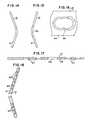
- FIG. 1is a top plan view of a small, left distal radial dorsal plate of the bone plating system of the present invention, the small, right distal radial dorsal plate is a mirror image thereof.
- FIG. 2is a first side elevational view of the dorsal plate of FIG. 1 .
- FIG. 3is a bottom plan view of the dorsal plate of FIG. 1 .
- FIG. 4is a second side elevational view of the dorsal plate of FIG. 1 .
- FIG. 5is a distal end view of the dorsal plate of FIG. 1 .
- FIG. 6is a proximal end view of the dorsal plate of FIG. 1 .
- FIG. 7is an enlarged view of a portion of FIG. 1, showing a spherically recessed longitudinal slot thereof.
- FIG. 8is a sectional view substantially as taken on line 8 — 8 of FIG. 1, on an enlarged scale and with portions thereof broken away for clarity.
- FIG. 9is a sectional view substantially as taken on line 9 — 9 of FIG. 1, on an enlarged scale and with portions thereof broken away for clarity.
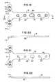
- FIG. 10is a top plan view of a large, left distal radial dorsal plate of the bone plating system of the present invention, the large, right distal radial dorsal plate being a mirror image thereof.
- FIG. 11is a first side elevational view of the dorsal plate of FIG. 10 .
- FIG. 12is a bottom plan view of the dorsal plate of FIG. 10 .
- FIG. 13is a second side elevational view of the dorsal plate of FIG. 10 .
- FIG. 14is a distal end view of the dorsal plate of FIG. 10 .
- FIG. 15is a proximal end view of the dorsal plate of FIG. 10 .
- FIG. 16is an enlarged view of a portion of FIG. 10, showing a spherically recessed longitudinal slot thereof.
- FIG. 17is a sectional view substantially as taken on line 17 — 17 of FIG. 10, on an enlarged scale and with portions thereof broken away for clarity.
- FIG. 18is a sectional view substantially as taken on line 18 — 18 of FIG. 10, on an enlarged scale and with portions thereof broken away for clarity.
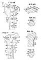
- FIG. 20is a first side elevational view of the volar plate of FIG. 19 .
- FIG. 21is a bottom plan view of the volar plate of FIG. 19 .
- FIG. 22is a second side elevational view of the volar plate of FIG. 19 .
- FIG. 23is a distal end view of the volar plate of FIG. 19 .
- FIG. 24is a proximal end view of the volar plate of FIG. 19 .
- FIG. 25is an enlarged view of a portion of FIG. 19, showing a spherically recessed longitudinal slot thereof.
- FIG. 26is a sectional view substantially as taken on line 26 — 26 of FIG. 19, on an enlarged scale and with portions thereof broken away for clarity.
- FIG. 27is a sectional view substantially as taken on line 27 — 27 of FIG. 19, on an enlarged scale and with portions thereof broken away for clarity.
- FIG. 28is as a top plan view of a distal radial plate extender of the bone plating system of the present invention.
- FIG. 29is a first side elevational view of the distal radial plate extender of FIG. 28, the second side being a mirror image thereof.
- FIG. 30is a first end view of the distal radial plate extender of FIG. 28 .
- FIG. 31is a bottom plan view of the distal radial plate extender of FIG. 28 .
- FIG. 32is a proximal end view of the distal radial plate extender of FIG. 28 .
- FIG. 33is a sectional view substantially as taken on line 33 — 33 of FIG. 28 .
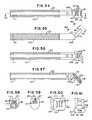
- FIG. 34is a top plan view of a buttress pin of the bone plating system of the present invention.
- FIG. 35is a sectional view substantially as taken on linen 35 — 35 of FIG. 34 .
- FIG. 36is a front elevational view of the buttress pin of FIG. 34, the rear and side elevational views being substantially mirror images thereof.
- FIG. 37is a bottom plan view of the buttress pin of FIG. 34 .
- FIG. 38is a top plan view of a buttress pin with soft tissue suture anchor means of the bone plating system of the present invention.
- FIG. 39is a sectional view substantially as taken on line 39 — 39 of FIG. 38 .
- FIG. 40is a front elevational view of the buttress pin of FIG. 38, the rear and side elevational views being substantially mirror images thereof.
- FIG. 41is a sectional view substantially as taken on line 41 — 41 of FIG. 40 .
- FIG. 42is a bottom plan view of the buttress pin of FIG. 38 .
- FIG. 43is a top plan view of a buttress pin screw lock pin shank of the bone plating system of the present invention.
- FIG. 44is a sectional view substantially as taken on line 44 — 44 of FIG. 43 .
- FIG. 47is a bottom plan view of the screw lock pin shank of FIG. 43 .
- FIG. 48is a perspective view of the screw lock pin shank of FIG. 43 .
- FIG. 49is a top plan view of a buttress pin screw lock pin head of the bone plating system of the present invention.
- FIG. 50is a sectional view substantially as taken on line 50 — 50 of FIG. 49 .
- FIG. 51is a front elevational view of the screw lock pin head of FIG. 49, the rear and side elevational views being substantially mirror images thereof.
- FIG. 52is a bottom plan view of the screw lock pin head of FIG. 49 .
- FIG. 53is a perspective view of the screw lock pin head of FIG. 49 .
- FIG. 54is a top plan view of a slotted plate bender of the bone plating system of the present invention.
- FIG. 55is a side elevational view of the slotted plate bender of FIG. 54, the other side being a mirror image thereof.
- FIG. 56is a bottom plan view of the slotted plate bender of FIG. 54 .
- FIG. 57is a sectional view substantially as taken on line 57 — 57 of FIG. 54 .
- FIG. 58is a left end view of the slotted plate bender of FIG. 54 .
- FIG. 59is a right end view of the slotted plate bender of FIG. 54 .
- FIG. 60is a normal view of a portion of the slotted plate bender of FIG. 54, substantially as taken on line 60 — 60 of FIG. 55 on a somewhat enlarged scale.
- FIG. 61is a normal view of a portion of the slotted plate bender of FIG. 54, substantially as taken on line 61 — 61 of FIG. 55 on a somewhat enlarged scale.
- FIG. 62is a front plan view of a drill guide of the bone plating system of the present invention.
- FIG. 63is a side elevational view of the drill guide of FIG. 62, the other side being substantially a mirror image thereof.
- FIG. 64is a rear plan view of the drill guide of FIG. 62 .
- FIG. 65is a top plan view of the drill guide of FIG. 62 .
- FIG. 66is a bottom plan view of the drill guide of FIG. 62 .
- FIG. 67is a sectional view substantially as taken on line 67 — 67 of FIG. 62, on a somewhat enlarged scale.
- FIG. 68is a somewhat diagrammatic dorsal view of the distal end of a radius, showing a small, right distal radial dorsal plate of the bone plating system of the present invention attached thereto, with parts thereof omitted for clarity.
- FIG. 69is a somewhat diagrammatic sectional view substantially as taken on line 69 — 69 of FIG. 68, with portions thereof broken away for clarity.
- FIG. 70is a somewhat diagrammatic sectional view substantially as taken on line 70 — 70 of FIG. 68, with portions thereof omitted for clarity.
- FIG. 71is a somewhat diagrammatic volar view of the distal end of a radius, showing a universal distal radial volar plate of the bone plating system of the present invention attached thereto, with parts thereof omitted for clarity.
- FIG. 72is a somewhat diagrammatic sectional view substantially as taken on line 72 — 72 of FIG. 71 .
- FIG. 73is a somewhat diagrammatic sectional view substantially as taken on line 73 - 71 of FIG. 71, with portions thereof omitted for clarity.
- FIG. 74is a somewhat diagrammatic dorsal view of the distal end of a radius, showing a small, right distal radial dorsal plate and a distal radial plate extender of the bone plating system of the present invention attached thereto, with parts thereof omitted for clarity.
- FIG. 75is a somewhat diagrammatic sectional view substantially as taken on line 75 — 75 of FIG. 74, with portions thereof broken away for clarity.
- FIG. 76is a somewhat diagrammatic sectional view of a portion of a longitudinal segment of the small, left distal radial dorsal plate, showing a low profile head bone screw securing the dorsal plate to a radius.
- FIG. 77is a somewhat diagrammatic sectional view of a portion of a transverse segment of the small, left distal radial dorsal plate, showing a buttress pin securing the dorsal plate to a radius.
- the preferred embodiment of the bone plating system of the present inventionis used for both intra- and extra-articular fractures of the distal radius, and may include a small, left distal radial dorsal plate as shown generally in FIGS. 1-9 and identified by the numeral 11 ; a small, right distal radial dorsal plate (shown diagrammatically in FIGS. 68-70, 74 and 75 , and being a mirror image of the small, left distal radial dorsal plate 11 ); a large, left distal radial dorsal plate as shown generally in FIGS.
- a large, right distal radial dorsal plate(not shown but being a mirror image of the large, left distal radial dorsal plate 13 ); a universal distal radial volar plate as shown generally in FIGS. 19-27 and identified by the numeral 15 ; a distal radial plate extender as shown generally in FIGS. 28-33 and identified by the numeral 17 ; a buttress pin as shown generally in FIGS. 34-37 and identified by the numeral 19 ; a buttress pin with soft tissue suture anchor means as shown generally in FIGS.
- the small, left distal radial dorsal plate 11is preferably substantially T-shaped in plan (see, in general, FIGS. 1 and 3 ).
- the dorsal plate 11includes a longitudinal segment 32 having a proximal end 33 and a distal end 34 .
- the longitudinal segment 32preferably has a plurality of spherically recessed holes 35 to accept bone screws 37 (see FIG. 76 ).
- This longitudinal segment 32also has a longitudinal slot 39 for use with bone screws 37 to compress fractures.
- the longitudinal slot 39has a distal end 40 and a proximal end 41 .
- the distal end 40 of this slot 39has a spherical recess.
- the proximal end 41 of this slot 39has a beveled edge which converges distally with the spherical edges or recess of the distal end 40 of the slot 39 to create a compression feature so that as a bone screw 37 with a spherical head is seated against this beveled edge, the plate 11 will slide proximally to seat the head of the screw 37 in the spherically recessed distal portion or end 40 of the slot 39 .
- the dorsal plate 11includes a transverse segment 42 having a lateral end 43 and a medial end 44 .
- the transverse segment 42preferably has a plurality of spherically recessed holes 45 to accept buttress pins 19 (see FIG.
- the holes 45preferably have a counterbore 47 on the bottom side of the plate 11 in order to create a locking feature for the buttress pins 19 , buttress pins 21 , and/or buttress pin screw lock pin shank 23 and pin head 25 combinations.
- the transverse segment 42preferably has a transverse, recessed slot 49 connected to the hole 45 on the lateral end 43 of this transverse segment 42 , on the bottom face 51 of the plate 11 and which extends laterally from this last hole 45 , increasing in width, through the lateral end 43 of the transverse segment 42 .
- the plate 11preferably has a low profile and smooth finish so as to minimize tendon irritation.
- the plate 11is preferably constructed of a surgical grade stainless steel. More specifically, based on the strength necessary and the clinical history of other currently marketed distal radial plating systems, high strength 316 L stainless steel is preferably used to construct the plate 11 to allow the plate 11 to be constructed as thin as possible and the thinnest material possible without sacrificing strength, and to provide pliability of the plate 11 for precise fitting.
- the small, right distal radial dorsal plateis a mirror image of the small, left distal radial dorsal plate 11 , and the above disclosure of the small, left distal radial dorsal plate 11 will provide a full and enabling teaching of the small, right distal radial dorsal plate to one of ordinary skill in the art.
- the small, right distal radial dorsal plateis shown diagrammatically in FIGS. 68-70, 74 and 75 , with like features identified with the same reference numbers as used for the small, left distal radial dorsal plate 11 .
- the large, left distal radial dorsal plate 13is preferably identical in design and construction to the small, left distal radial dorsal plate 11 , and is preferably substantially T-shaped in plan (see, in general, FIGS. 10 and 12 ), with a proximal longitudinal segment 55 , a plurality of spherically recessed holes 57 and a spherically recessed longitudinal slot 59 in the proximal longitudinal segment 55 , a distal transverse segment 61 , a plurality of spherically recessed holes 63 in the distal transverse segment 61 , etc.
- the large, right distal radial dorsal plateis a mirror image of the large, left distal radial dorsal plate 13 , and the above disclosure of the large, left distal radial dorsal plate 13 will provide a full and enabling teaching of the large, right distal radial dorsal plate to one of ordinary skill in the art.
- the proximal end 71 of this slot 69has a beveled edge which converges distally with the spherical edges of the slot 69 to create a compression feature so that as a bone screw 37 with a spherical head is seated against this beveled edge, the plate 15 will slide proximally to seat the head of the screw 37 in the spherically recessed portion of the slot 69 .
- the volar plate 15includes a transverse segment 73 preferably having a plurality of spherically recessed holes 75 to accept buttress pins 19 , buttress pins 21 , buttress pin screw lock pin shank 23 and pin head 25 combinations, and/or bone screws 37 .
- the holes 75preferably have a counterbore 47 on the bottom side of the plate 11 in order to create a locking feature for the buttress pins 19 , buttress pins 21 , and/or buttress pin screw lock pin shank 23 and pin head 25 combinations.
- This distal transverse segment 73 of the plate 15also preferably has a central divot 77 .
- the distal end of the plate 15is preferably pre-bent to approximately a 155° angle (see, in general, FIGS. 20 and 22) so that its bottom face 79 conforms as closely as possible to the surface of the distal radius R (see, in general, FIG. 72 ).
- the plate 15preferably has a low profile and smooth finish so as to minimize tendon irritation.
- the plate 15is preferably constructed of a surgical grade stainless steel. More specifically, based on the strength necessary and the clinical history of other currently marketed distal radial plating systems, high strength 316L stainless steel is preferably used to construct the plate 15 to allow the plate 15 to be constructed as thin as possible and the thinnest material possible without sacrificing strength, and to provide pliability of the plate 15 for precess fitting.
- the volar plate 15is not side specific and may be offered in only one size.
- the distal radial plate extender 17mates with the bottom side of, e.g., the small, left distal radial dorsal plate 11 (or the large, left distal radial dorsal plate 13 , or the small or large right distal radial dorsal plates) to provide an additional hole on the lateral side of the head or transverse segment 42 of the dorsal plate 11 , etc.
- the extender 17preferably has a first end 81 , a second end 83 , and a midportion 85 joining the first and second ends 81 , 83 .
- the second end 83has a boss portion 86 sized to extend into and seat in the most distal spherically recessed hole 45 in the dorsal plate 11 , with the midportion 85 located in the transverse, recessed slot 49 , etc.
- the distal radial plate extender 17preferably has a first spherically recessed hole 87 in the first end 81 thereof and a second spherically recessed hole 89 in the second end 83 thereof. The distal radial plate extender 17 eliminates the trimming and filing debris associated with an attached hole found in other systems.
- the distal radial plate extender 17is preferably constructed out of stainless steel.
- the buttress pins 19 , 21 and buttress pin combination 23 , 25are for use with a fracture fixation plate, specifically a distal radial dorsal or volar plate as disclosed herein, for the positioning of small bone fragments (the following description of the buttress pins 19 , 21 and buttress pin combination 23 , 25 will be in combination with the small, left distal radial dorsal plate 11 but it should be understood that the buttress pin 19 , 21 and buttress pin combination 23 , 25 are not limited for use with the small, left distal radial dorsal plate 11 ).
- Each buttress pin 19 , 21 and the buttress pin screw lock pin shank 23includes a shank 91 for extending through one of the spherically recessed holes 45 in the transverse segment 42 of the distal radial dorsal plate 11 , and into a bone fragment of the distal radius R (see, for example, FIG. 77 ).
- Each buttress pin 19 , 21 and the buttress pin screw lock pin shank 23includes a collar 93 attached to the shank 91 for locking the distal radial dorsal plate 11 to the corresponding buttress pin 19 , 21 or buttress pin screw lock pin shank 23 .
- the collar 93has a recessed groove 95 thereabout and is movable between a first position for allowing the collar 93 to be inserted into one of the spherically recessed holes 45 in the transverse segment 42 of the distal radial dorsal plate 11 , and a second position in which the recessed groove 95 of the collar 93 captures at least a portion of the edge of that spherically recessed hole 45 in the transverse segment 42 of the distal radial dorsal plate 11 to lock the distal radial dorsal plate 11 and the corresponding buttress pin 19 , 21 or buttress pin screw lock pin shank 23 together.
- the head or collar 93will thus interlock with the hole 45 vial a “snap-lock.”
- the collar 93 of the buttress pins 19 , 21may have a slot 97 (preferably a pair of intersecting slots 97 as clearly shown in FIGS. 34 and 38) therein to allow the collar 93 to be compressed to the first position when inserted into a spherically recessed hole 45 in the transverse segment 42 of the distal radial dorsal plate 11 and to expand or spring back to the second position with the recessed groove 95 of the collar 93 capturing at least a portion of the edge of that spherically recessed hole 45 in the transverse segment 42 of the distal radial dorsal plate 11 .
- the collar 93 of the buttress pins 19 , 21may have a plurality of divots 99 (preferably four opposing divots 99 ) for allowing the collar 93 to be compressed from the second position to the first position (I.e., for use in the compression and removal of the pins 19 , 21 from the distal radial dorsal plate 11 ).
- the buttress pin 21includes means for allowing the pin to be attached to soft tissue. More specifically, the buttress pin 21 preferably has a hole 101 through the shank 91 thereof just beneath the collar 93 thereof for allowing a suture to extend therethrough to attach the buttress pin 21 to soft tissue.
- the buttress pin screw lock pin head 25is designed to extend into at least the collar 93 of the buttress pin screw lock pin shank 23 to cause that collar 93 to move from the first position to the second position.
- the buttress pin screw lock pin head 25preferably has a male screw portion 103
- the buttress pin screw lock pin shank 23preferably has a internally threaded aperture 105 in the collar 93 and shank 91 thereof for receiving the screw portion 103 whereby screwing the screw portion 103 into the internally threaded aperture 105 causes the collar 93 to expand from the first position to the second position.
- the buttress pin screw lock pin shank 23is first inserted into the desired hole 45 in the transverse segment 42 of the distal radial dorsal plate 11 until the collar 93 thereof “snaps-in” the hole 45 and the screw lock pin head 25 is then screwed into the screw lock pin shank 23 and tightened, causing the collar 93 to expand and locking the unit ( the buttress pin combination 23 , 25 and the distal radial dorsal plate 11 ) together in a very solid connection.
- the buttress pins 19 , 21 and buttress pin combination 23 , 25are preferably constructed out of stainless steel.
- the slotted plate bender 27is designed for use in bending and molding a fracture fixation plate to match the anatomy of a specific radius R.
- the plate bender 27is specifically designed for use with a distal radial dorsal or volar plate as disclosed herein and the following description of the plate bender 27 will be in combination with the small, left distal radial dorsal plate 11 but it should be understood that the plate bender 27 is not limited for use with the small, left distal radial dorsal plate 11 .
- the plate bender 27includes an elongated, preferably round, handle 107 having a first end 109 and a second end 111 .
- the plate bender 27includes a tip 113 attached to the first end 109 of the elongated handle 107 at an angle thereto.
- the tip 113has an end surface 115 and a face surface 117 substantially perpendicular to the end surface 115 .
- the tip 113has a first slot 119 extending through the end surface 115 for receiving an end of the transverse segment 42 of the plate 11 , and has a plurality of slots 121 extending through the face surface 117 thereof for receiving an end of the longitudinal segment 32 of the plate 11 , or the longitudinal segment 65 or transverse segment 73 of the volar plate 15 .
- the angled tip 113in combination with the elongated handle 107 , provides leverage for bending the plate 11 . At least portions of the surface of the handle 107 may be knurled or otherwise formed to provide a secure grip.
- the plate bender 27is preferably constructed out of stainless steel.
- the drill guide 29 shown in FIGS. 62-67includes an elongated, substantially flat body 123 having an upturned first end 125 and an upturned second end 127 Each end 125 , 127 has an aperture 129 therethrough to allow a drill guide tip 131 to be inserted thereinto. Grooves 133 may be provide on the surface of the body 123 to allow the surgeon to securely grip the drill guide 29 .
- the drill guide tips 131are provided in various sizes depending on the size of screw, buttress pin, etc., to be used.
- a straight longitudinal incisionis made over the dorsal radius between the second and third dorsal extensor compartments and extending between 7 and 12 centimeters.
- the fracturecan then be identified and exposed, and the structures retracted on both sides of the distal radial shaft.
- the fracturecan be confirmed, reduced and/or brought out to length with distraction to verify this.
- the surgeoncan then decide what size plate 11 , 13 , etc., to use and if an extender 17 will be needed due to any floating radial styloid fragments.
- a malleable template of the selected plate 11 , 13 , etc.can then be placed and used to determine the appropriate contour of the fractured radius R. Removal of the Lister's tubercle may be necessary.
- the bender 27can then be used to match the selected plate 11 , 13 , etc., to the contoured template. Care should be taken not to bend the selected plate 11 , 13 , etc., across the holes 45 , etc., designed for use with buttress pins 19 , 21 or buttress pin combinations 23 , 25 . Appropriate screw size as well as screw and pin placement can then be determined. Screw and pin holes must be predrilled in the radius R with the appropriate drill and drill guide 29 .
- buttress pins 19 , 21 and buttress pin combinations 23 , 25are not to be used to either attach the extender 17 to the plate 11 , etc., or with the hole 89 in the extender 17 .
- the compression slot 39 in the middle of the longitudinal segment 32 of the plate 11 , etc.may be used.
- a holeis drilled at the proximal end 41 of the slot 39 , etc., so that as a screw is seated against the proximal end 41 of the slot 39 , the head of the screw will pull the entire plate proximally.
- an appropriate surgical approachis used with regard to the anterior aspect of the distal radius to provide adequate exposure while protecting the median and ulnar nerves, flexor tendons, and palmar capsular radiocarpal ligaments.
- the fracturecan then be identified and exposed, and the structures are retracted on both sides of the distal radial shaft. Then, under direct vision, the fracture is confirmed, reduced and/or brought out to length with distraction to verify this. After ensuring reduction through distraction or manual manipulation and with fluoroscopic X-rays, a surgeon can then place and contour the volar plate 15 . Care should be taken not to bend the volar plate 15 across the holes 75 designated for use with buttress pins. Attachment of the plate 15 with screws and buttress pins, etc., can follow the same procedures described hereinabove relative to the dorsal approach.
Landscapes
- Health & Medical Sciences (AREA)
- Orthopedic Medicine & Surgery (AREA)
- Surgery (AREA)
- Life Sciences & Earth Sciences (AREA)
- Heart & Thoracic Surgery (AREA)
- Veterinary Medicine (AREA)
- Engineering & Computer Science (AREA)
- Biomedical Technology (AREA)
- Nuclear Medicine, Radiotherapy & Molecular Imaging (AREA)
- Medical Informatics (AREA)
- Molecular Biology (AREA)
- Animal Behavior & Ethology (AREA)
- General Health & Medical Sciences (AREA)
- Public Health (AREA)
- Neurology (AREA)
- Dentistry (AREA)
- Oral & Maxillofacial Surgery (AREA)
- Surgical Instruments (AREA)
Abstract
Description
Claims (4)
Priority Applications (3)
| Application Number | Priority Date | Filing Date | Title |
|---|---|---|---|
| US09/522,088US6283969B1 (en) | 2000-03-10 | 2000-03-10 | Bone plating system |
| EP01250075AEP1132052B1 (en) | 2000-03-10 | 2001-03-09 | Bone plating system |
| DE60112492TDE60112492T2 (en) | 2000-03-10 | 2001-03-09 | Bone plate system |
Applications Claiming Priority (1)
| Application Number | Priority Date | Filing Date | Title |
|---|---|---|---|
| US09/522,088US6283969B1 (en) | 2000-03-10 | 2000-03-10 | Bone plating system |
Publications (1)
| Publication Number | Publication Date |
|---|---|
| US6283969B1true US6283969B1 (en) | 2001-09-04 |
Family
ID=24079416
Family Applications (1)
| Application Number | Title | Priority Date | Filing Date |
|---|---|---|---|
| US09/522,088Expired - LifetimeUS6283969B1 (en) | 2000-03-10 | 2000-03-10 | Bone plating system |
Country Status (3)
| Country | Link |
|---|---|
| US (1) | US6283969B1 (en) |
| EP (1) | EP1132052B1 (en) |
| DE (1) | DE60112492T2 (en) |
Cited By (162)
| Publication number | Priority date | Publication date | Assignee | Title |
|---|---|---|---|---|
| US6364882B1 (en)* | 2000-02-01 | 2002-04-02 | Hand Innovations, Inc. | Volar fixation system |
| USD458374S1 (en) | 2001-11-13 | 2002-06-04 | Zimmer, Inc. | Orthopaedic bone plate |
| USD458683S1 (en) | 2001-11-13 | 2002-06-11 | Zimmer, Inc. | Orthopaedic bone plate |
| US6440135B2 (en)* | 2000-02-01 | 2002-08-27 | Hand Innovations, Inc. | Volar fixation system with articulating stabilization pegs |
| US6508819B1 (en)* | 2001-08-28 | 2003-01-21 | Hand Innovations, Inc. | Method of dorsal wrist fracture fixation |
| USD469874S1 (en) | 2002-04-26 | 2003-02-04 | Zimmer, Inc. | Orthopaedic bone plate |
| USD470588S1 (en) | 2002-04-26 | 2003-02-18 | Zimmer, Inc. | Orthopaedic bone plate |
| WO2003020007A3 (en)* | 2001-08-28 | 2003-04-10 | Hand Innovations Inc | Method and apparatus for dorsal wrist fracture fixation |
| US20030083660A1 (en)* | 2000-02-01 | 2003-05-01 | Hand Innovations, Inc. | Bone fracture fixation systems with both multidirectional and unidirectional stabilization pegs |
| US6652530B2 (en)* | 2001-09-19 | 2003-11-25 | The University Of Hong Kong | Fixation device |
| WO2003047416A3 (en)* | 2001-11-30 | 2003-12-04 | Univ Minnesota | Wrist surgery devices and techniques |
| US20040010255A1 (en)* | 2000-09-22 | 2004-01-15 | Warburton Mark J. | Intramedullary interlocking fixation device for the distal radius |
| US6712820B2 (en)* | 2000-02-01 | 2004-03-30 | Hand Innovations, Inc. | Fixation plate system for dorsal wrist fracture fixation |
| US20040102775A1 (en)* | 2002-11-19 | 2004-05-27 | Huebner Randall J. | Bone plates with slots |
| US6767351B2 (en) | 2000-02-01 | 2004-07-27 | Hand Innovations, Inc. | Fixation system with multidirectional stabilization pegs |
| US20040167522A1 (en)* | 2001-05-28 | 2004-08-26 | Alfred Niederberger | Bone plate |
| US20040193164A1 (en)* | 2003-03-27 | 2004-09-30 | Orbay Jorge L. | Anatomical distal radius fracture fixation plate and methods of using the same |
| US20040193165A1 (en)* | 2003-03-27 | 2004-09-30 | Hand Innovations, Inc. | Anatomical distal radius fracture fixation plate and methods of using the same |
| US20050065524A1 (en)* | 2003-03-27 | 2005-03-24 | Orbay Jorge L. | Anatomical distal radius fracture fixation plate with fixed-angle K-wire holes defining a three-dimensional surface |
| US20050065523A1 (en)* | 2003-03-27 | 2005-03-24 | Orbay Jorge L. | Distal radius fracture fixation plate having K-wire hole structured to fix a K-wire in one dimension relative to the plate |
| US20050065522A1 (en)* | 2003-03-27 | 2005-03-24 | Orbay Jorge L. | Low profile distal radius fracture fixation plate |
| US20050165401A1 (en)* | 2004-01-26 | 2005-07-28 | Larry Pack | Pelvic fixation plate |
| DE10356904A1 (en)* | 2003-11-05 | 2005-09-22 | Königsee Implantate und Instrumente zur Osteosynthese GmbH | Plate for stabilizing distal radius fractures comprises an anatomically performed plate part having a triangular shape which is irregular |
| US20050277940A1 (en)* | 2004-06-15 | 2005-12-15 | Neff James R | Dynamic compression device and driving tool |
| US20060004362A1 (en)* | 2004-07-02 | 2006-01-05 | Patterson Chad J | Distal radius bone plating system with locking and non-locking screws |
| US7081119B2 (en) | 2003-08-01 | 2006-07-25 | Hfsc Company | Drill guide assembly for a bone fixation device |
| US20060173458A1 (en)* | 2004-10-07 | 2006-08-03 | Micah Forstein | Bone fracture fixation system |
| US7090676B2 (en)* | 2002-11-19 | 2006-08-15 | Acumed Llc | Adjustable bone plates |
| US20060241616A1 (en)* | 2002-12-31 | 2006-10-26 | Depuy Spine, Inc. | Bone Plate and Resilient Screw System Allowing Bi-Directional Assembly |
| US7153309B2 (en) | 2002-11-19 | 2006-12-26 | Acumed Llc | Guide system for bone-repair devices |
| US7189237B2 (en) | 2002-11-19 | 2007-03-13 | Acumed Llc | Deformable bone plates |
| US20070083202A1 (en)* | 2005-09-20 | 2007-04-12 | Donald Eli Running | Intramedullary bone plate with sheath |
| US20070083204A1 (en)* | 2005-09-16 | 2007-04-12 | Sidebotham Christopher G | Multi-purpose bone plate system |
| US20070123880A1 (en)* | 2005-10-25 | 2007-05-31 | Robert Medoff | Bone fixation device and method |
| US20070123886A1 (en)* | 2003-11-05 | 2007-05-31 | Koenigsee Implantate U. Inst. Zur Osteosynth. Gmbh | Plate used to stabilise distal radius fractures |
| US7229445B2 (en) | 2004-06-21 | 2007-06-12 | Synthes (Usa) | Bone plate with bladed portion |
| US20070162015A1 (en)* | 1998-03-31 | 2007-07-12 | Zimmer Technology, Inc. | Orthopaedic bone plate |
| US20070173839A1 (en)* | 2006-01-10 | 2007-07-26 | Running Donald E | Fracture fixation plate with cover sheath |
| US20070239163A1 (en)* | 2006-03-07 | 2007-10-11 | Strnad Lee A | Orthopedic Plate |
| US20070260244A1 (en)* | 2004-07-19 | 2007-11-08 | Dietmar Wolter | Bone-Fixation System and Filler Element for Bone-Fixation |
| US20070270849A1 (en)* | 2006-04-21 | 2007-11-22 | Orbay Jorge L | Fixation Plate With Multifunctional Holes |
| WO2007100513A3 (en)* | 2006-02-24 | 2007-12-13 | Synthes Usa | Tibial plateau leveling osteotomy plate |
| US7316687B2 (en)* | 2001-08-24 | 2008-01-08 | Zimmer Technology, Inc. | Blade plate and instruments |
| US20080051786A1 (en)* | 2006-04-03 | 2008-02-28 | Acumed Llc | Bone plates with hybrid apertures |
| US7357804B2 (en) | 2003-08-13 | 2008-04-15 | Synthes (U.S.A.) | Quick-release drill-guide assembly for bone-plate |
| US20080140127A1 (en)* | 2006-12-06 | 2008-06-12 | Amei Technologies, Inc. | Volar plate fixation device |
| USD576731S1 (en)* | 2007-01-17 | 2008-09-09 | Orthohelix Surgical Designs, Inc. | Orthopedic plate |
| US7425213B2 (en) | 2002-12-10 | 2008-09-16 | Depuy Products, Inc. | Method of endosteal nailing |
| USD580057S1 (en)* | 2006-11-10 | 2008-11-04 | Wright Medical Technology, Inc. | Orthopaedic implant |
| US20080281327A1 (en)* | 2007-05-07 | 2008-11-13 | Stryker Trauma | Sliding plate with reinforced slot |
| US20090048599A1 (en)* | 2007-08-16 | 2009-02-19 | Hajianpour Mohammed A | External fixation apparatus with adjustable pin clamping means |
| US7537603B2 (en) | 2002-07-22 | 2009-05-26 | Acumed Llc | Bone fusion system |
| US7537596B2 (en) | 2003-06-20 | 2009-05-26 | Acumed Llc | Bone plates with intraoperatively tapped apertures |
| US7563263B2 (en) | 2000-02-01 | 2009-07-21 | Depuy Products, Inc. | Intramedullary fixation device for metaphyseal long bone fractures |
| US7578825B2 (en) | 2004-04-19 | 2009-08-25 | Acumed Llc | Placement of fasteners into bone |
| US7588577B2 (en) | 2004-07-15 | 2009-09-15 | Wright Medical Technology, Inc. | Guide assembly for intramedullary fixation and method of using the same |
| US7635365B2 (en) | 2003-08-28 | 2009-12-22 | Ellis Thomas J | Bone plates |
| US20100057132A1 (en)* | 2008-09-03 | 2010-03-04 | Mimedx Inc., Corporation of the State of Florida | Modular bone fixation device for treatment of fractures and related methods |
| US20100057215A1 (en)* | 2008-09-03 | 2010-03-04 | Mimedx Inc. | Arthroplastic implant with anchor peg for basilar joint and related methods |
| US20100057213A1 (en)* | 2008-09-03 | 2010-03-04 | Mimedx Inc., Corporation of the State of Florida | Arthroplastic implant with shield for basilar joint and related methods |
| US20100057214A1 (en)* | 2008-09-03 | 2010-03-04 | Mimedx, Inc., Corporation of the State of Florida | Arthrodesis implant for finger joints and related methods |
| US7695502B2 (en) | 2000-02-01 | 2010-04-13 | Depuy Products, Inc. | Bone stabilization system including plate having fixed-angle holes together with unidirectional locking screws and surgeon-directed locking screws |
| US7717945B2 (en) | 2002-07-22 | 2010-05-18 | Acumed Llc | Orthopedic systems |
| US7727264B2 (en) | 2000-02-01 | 2010-06-01 | Depuy Products, Inc. | Intramedullary fixation device for metaphyseal long bone fractures |
| US7731721B2 (en) | 2003-07-16 | 2010-06-08 | Synthes Usa, Llc | Plating system with multiple function drill guide |
| US20100152783A1 (en)* | 2008-12-11 | 2010-06-17 | Veterinary Implants Direct, Llc | Universal Surgical Plate with 30 Degree Compression Angle |
| US20100305618A1 (en)* | 2005-01-28 | 2010-12-02 | Orthohelix Surgical Designs, Inc. | Orthopedic plate |
| US7846162B2 (en) | 2005-05-18 | 2010-12-07 | Sonoma Orthopedic Products, Inc. | Minimally invasive actuable bone fixation devices |
| US20110004252A1 (en)* | 2009-07-04 | 2011-01-06 | Jordan Velikov | Plate for the treatment of bone fractures |
| US7905909B2 (en) | 2005-09-19 | 2011-03-15 | Depuy Products, Inc. | Bone stabilization system including multi-directional threaded fixation element |
| US7909825B2 (en) | 2006-11-22 | 2011-03-22 | Sonoma Orthepedic Products, Inc. | Fracture fixation device, tools and methods |
| US7914561B2 (en) | 2002-12-31 | 2011-03-29 | Depuy Spine, Inc. | Resilient bone plate and screw system allowing bi-directional assembly |
| US7951176B2 (en) | 2003-05-30 | 2011-05-31 | Synthes Usa, Llc | Bone plate |
| US20110137314A1 (en)* | 2009-07-06 | 2011-06-09 | Zimmer, Gmbh | Periprosthetic bone plates |
| US7981142B2 (en) | 2002-12-31 | 2011-07-19 | Depuy Spine, Inc. | Bone plate and screw system allowing bi-directional assembly |
| US20110213421A1 (en)* | 2004-04-19 | 2011-09-01 | Lawrence Binder | Bone Fixation Plate |
| US20110218534A1 (en)* | 2010-03-08 | 2011-09-08 | Bernard Prandi | Adjustable-angle radius plate |
| US20110218533A1 (en)* | 2010-03-08 | 2011-09-08 | Bernard Prandi | Radius-plate assembly |
| US20120010667A1 (en)* | 2009-03-23 | 2012-01-12 | Eglseder W Andrew | Fracture-specific distal radius plates |
| US20120095466A1 (en)* | 2010-10-19 | 2012-04-19 | Biomet Manufacturing Corp. | Orthopedic Plate Assembly for a Distal Radius Having Re-Contouring Features and Method for Using Same |
| US8177819B2 (en) | 2004-04-22 | 2012-05-15 | Acumed Llc | Expanded fixation of bones |
| US20120209333A1 (en)* | 2011-02-14 | 2012-08-16 | Skeletal Dynamics, L.L.C. | Fracture fixation plate |
| US8287541B2 (en) | 2005-05-18 | 2012-10-16 | Sonoma Orthopedic Products, Inc. | Fracture fixation device, tools and methods |
| US8419745B2 (en) | 2010-04-23 | 2013-04-16 | Biomet C.V. | Bone plate bender system |
| US8568417B2 (en) | 2009-12-18 | 2013-10-29 | Charles River Engineering Solutions And Technologies, Llc | Articulating tool and methods of using |
| US8591554B2 (en) | 2010-05-07 | 2013-11-26 | Osteomed Llc | System for treating bone fractures |
| US8771283B2 (en) | 2007-12-17 | 2014-07-08 | Wright Medical Technology, Inc. | Guide assembly for intramedullary fixation and method of using the same |
| US20140296923A1 (en)* | 2005-01-28 | 2014-10-02 | Orthohelix Surgical Designs, Inc. | Orthopedic plates for use in clavicle repair and methods for their use |
| US8961516B2 (en) | 2005-05-18 | 2015-02-24 | Sonoma Orthopedic Products, Inc. | Straight intramedullary fracture fixation devices and methods |
| US9060820B2 (en) | 2005-05-18 | 2015-06-23 | Sonoma Orthopedic Products, Inc. | Segmented intramedullary fracture fixation devices and methods |
| US9101421B2 (en) | 2011-12-12 | 2015-08-11 | Solana Surgical, Llc | Metatarsal fixation device, system and method |
| US20150223851A1 (en)* | 2014-02-12 | 2015-08-13 | Centric Medical, LLC | Foot Bone Plate Providing Fixation and Compression |
| US9155574B2 (en) | 2006-05-17 | 2015-10-13 | Sonoma Orthopedic Products, Inc. | Bone fixation device, tools and methods |
| WO2015160022A1 (en)* | 2014-04-18 | 2015-10-22 | 백혜선 | Fixing tool for open-wedge high tibial osteotomy |
| US9220549B2 (en) | 2011-09-27 | 2015-12-29 | Steven Glickel | Distal radius volar locking plate with extension for ulnar volar fragment |
| US9237910B2 (en) | 2012-01-26 | 2016-01-19 | Acute Innovations Llc | Clip for rib stabilization |
| CN105326551A (en)* | 2014-08-11 | 2016-02-17 | 天津市康尔医疗器械有限公司 | Double-column locking plate for distal radius palmaris |
| US9408646B2 (en) | 2003-09-03 | 2016-08-09 | DePuy Synthes Products, Inc. | Bone plate with captive clips |
| US9414870B2 (en) | 2003-09-03 | 2016-08-16 | DePuy Synthes Products, Inc. | Translatable carriage fixation system |
| US9451971B2 (en) | 2004-07-15 | 2016-09-27 | Agilent Technologies, Inc. | Intramedullary fixation assembly and devices and methods for installing the same |
| US9526543B2 (en) | 2004-11-10 | 2016-12-27 | Biomet C.V. | Modular fracture fixation system |
| US9770278B2 (en) | 2014-01-17 | 2017-09-26 | Arthrex, Inc. | Dual tip guide wire |
| US9775657B2 (en) | 2011-09-30 | 2017-10-03 | Acute Innovations Llc | Bone fixation system with opposed mounting portions |
| US9814499B2 (en) | 2014-09-30 | 2017-11-14 | Arthrex, Inc. | Intramedullary fracture fixation devices and methods |
| US9833270B2 (en) | 2013-09-19 | 2017-12-05 | Mcginley Engineered Solutions, Llc | Variable angle blade plate system and method |
| US9839463B2 (en) | 2012-09-06 | 2017-12-12 | Stryker European Holdings I, Llc | Instrument for use in bending surgical devices |
| US9956015B2 (en) | 2014-07-03 | 2018-05-01 | Acumed Llc | Bone plate with movable joint |
| US10321942B2 (en) | 2014-06-17 | 2019-06-18 | Life Spine, Inc. | Compression screw systems for compressing bones of the extremities |
| US10335211B2 (en) | 2004-01-26 | 2019-07-02 | DePuy Synthes Products, Inc. | Highly-versatile variable-angle bone plate system |
| US10342586B2 (en) | 2003-08-26 | 2019-07-09 | DePuy Synthes Products, Inc. | Bone plate |
| US10368928B2 (en) | 2017-03-13 | 2019-08-06 | Globus Medical, Inc. | Bone stabilization systems |
| US10383668B2 (en) | 2016-08-17 | 2019-08-20 | Globus Medical, Inc. | Volar distal radius stabilization system |
| US10420596B2 (en) | 2016-08-17 | 2019-09-24 | Globus Medical, Inc. | Volar distal radius stabilization system |
| US10420595B2 (en)* | 2015-09-25 | 2019-09-24 | Li Ming | Universal self-locking anatomical plate for posterior of acetabulum and pelvis |
| US10575884B2 (en) | 2016-08-17 | 2020-03-03 | Globus Medical, Inc. | Fracture plates, systems, and methods |
| US10624686B2 (en) | 2016-09-08 | 2020-04-21 | DePuy Synthes Products, Inc. | Variable angel bone plate |
| US10631903B2 (en) | 2017-03-10 | 2020-04-28 | Globus Medical Inc. | Clavicle fixation system |
| US10687873B2 (en) | 2016-08-17 | 2020-06-23 | Globus Medical Inc. | Stabilization systems |
| US10687874B2 (en) | 2015-08-27 | 2020-06-23 | Globus Medical, Inc | Proximal humeral stabilization system |
| US10751098B2 (en) | 2016-08-17 | 2020-08-25 | Globus Medical Inc. | Stabilization systems |
| US10772665B2 (en) | 2018-03-29 | 2020-09-15 | DePuy Synthes Products, Inc. | Locking structures for affixing bone anchors to a bone plate, and related systems and methods |
| US10820930B2 (en) | 2016-09-08 | 2020-11-03 | DePuy Synthes Products, Inc. | Variable angle bone plate |
| US10828075B2 (en) | 2015-09-25 | 2020-11-10 | Globus Medical Inc. | Bone fixation devices having a locking feature |
| US10828074B2 (en) | 2015-11-20 | 2020-11-10 | Globus Medical, Inc. | Expandalbe intramedullary systems and methods of using the same |
| US10856920B2 (en) | 2017-09-13 | 2020-12-08 | Globus Medical Inc. | Bone stabilization systems |
| WO2021003583A1 (en) | 2019-07-11 | 2021-01-14 | Bonebridge Ag | Fracture fixation plate for application to the proximal humerus |
| US10905476B2 (en) | 2016-09-08 | 2021-02-02 | DePuy Synthes Products, Inc. | Variable angle bone plate |
| US10905477B2 (en) | 2017-03-13 | 2021-02-02 | Globus Medical, Inc. | Bone stabilization systems |
| US10925651B2 (en) | 2018-12-21 | 2021-02-23 | DePuy Synthes Products, Inc. | Implant having locking holes with collection cavity for shavings |
| US10940023B2 (en) | 2016-12-15 | 2021-03-09 | Stryker European Holdings I, Llc | Bone plate trial |
| US11013541B2 (en) | 2018-04-30 | 2021-05-25 | DePuy Synthes Products, Inc. | Threaded locking structures for affixing bone anchors to a bone plate, and related systems and methods |
| US11026727B2 (en) | 2018-03-20 | 2021-06-08 | DePuy Synthes Products, Inc. | Bone plate with form-fitting variable-angle locking hole |
| US11071570B2 (en) | 2018-03-02 | 2021-07-27 | Globus Medical, Inc. | Distal tibial plating system |
| US11076898B2 (en) | 2015-08-27 | 2021-08-03 | Globus Medical, Inc. | Proximal humeral stabilization system |
| US11096730B2 (en) | 2017-09-13 | 2021-08-24 | Globus Medical Inc. | Bone stabilization systems |
| US11129627B2 (en) | 2019-10-30 | 2021-09-28 | Globus Medical, Inc. | Method and apparatus for inserting a bone plate |
| US11141204B2 (en) | 2016-08-17 | 2021-10-12 | Globus Medical Inc. | Wrist stabilization systems |
| US11141172B2 (en) | 2018-04-11 | 2021-10-12 | Globus Medical, Inc. | Method and apparatus for locking a drill guide in a polyaxial hole |
| US11197701B2 (en) | 2016-08-17 | 2021-12-14 | Globus Medical, Inc. | Stabilization systems |
| US11197682B2 (en) | 2015-08-27 | 2021-12-14 | Globus Medical, Inc. | Proximal humeral stabilization system |
| US11197704B2 (en) | 2016-04-19 | 2021-12-14 | Globus Medical, Inc. | Implantable compression screws |
| US11202663B2 (en) | 2019-02-13 | 2021-12-21 | Globus Medical, Inc. | Proximal humeral stabilization systems and methods thereof |
| US11213327B2 (en) | 2016-08-17 | 2022-01-04 | Globus Medical, Inc. | Fracture plates, systems, and methods |
| US11219527B2 (en) | 2011-02-16 | 2022-01-11 | Genesis Medical Devices Llc | Combination intra-medullary and extra-medullary fracture stabilization with aligning arm |
| US11224468B2 (en) | 2018-03-02 | 2022-01-18 | Globus Medical, Inc. | Distal tibial plating system |
| US11259851B2 (en) | 2003-08-26 | 2022-03-01 | DePuy Synthes Products, Inc. | Bone plate |
| US11284920B2 (en) | 2016-03-02 | 2022-03-29 | Globus Medical Inc. | Fixators for bone stabilization and associated systems and methods |
| US11291484B2 (en) | 2004-01-26 | 2022-04-05 | DePuy Synthes Products, Inc. | Highly-versatile variable-angle bone plate system |
| US11331128B2 (en) | 2016-08-17 | 2022-05-17 | Globus Medical Inc. | Distal radius stabilization system |
| US11351030B2 (en) | 2019-07-11 | 2022-06-07 | Stryker European Operations Holdings Llc | Surgeon specific bone plates |
| US11426220B2 (en) | 2017-10-11 | 2022-08-30 | Howmedica Osteonics Corp. | Humeral fixation plate guides |
| US11432857B2 (en) | 2016-08-17 | 2022-09-06 | Globus Medical, Inc. | Stabilization systems |
| US20230056989A1 (en)* | 2021-08-17 | 2023-02-23 | Edward Perez | Bone fixation devices, systems, and methods |
| US11723647B2 (en) | 2019-12-17 | 2023-08-15 | Globus Medical, Inc. | Syndesmosis fixation assembly |
| US11864803B2 (en) | 2009-07-09 | 2024-01-09 | Orthohelix Surgical Designs, Inc. | Osteotomy plate, plate driver and method for their use |
| US11963847B2 (en) | 2021-11-03 | 2024-04-23 | DePuy Synthes Products, Inc. | TPLO plate compression system and method |
| US12042200B2 (en) | 2016-09-22 | 2024-07-23 | Globus Medical, Inc. | Systems and methods for intramedullary nail implantation |
| US12064150B2 (en) | 2022-01-19 | 2024-08-20 | Globus Medical Inc. | System and method for treating bone fractures |
| US12185995B2 (en) | 2019-10-09 | 2025-01-07 | Globus Medical, Inc. | Bone stabilization systems |
| US12279795B2 (en) | 2017-09-13 | 2025-04-22 | Globus Medical, Inc. | Bone stabilization systems |
| US12285197B2 (en) | 2008-10-10 | 2025-04-29 | Acumed Llc | Bone fixation system with opposed mounting portions |
| US12402923B2 (en) | 2022-10-04 | 2025-09-02 | DePuy Synthes Products, Inc. | Offset hole for TPLO compression |
Families Citing this family (16)
| Publication number | Priority date | Publication date | Assignee | Title |
|---|---|---|---|---|
| FR2829920B1 (en)* | 2001-09-26 | 2004-05-28 | Newdeal Sa | PLATE FOR FIXING THE BONES OF A JOINT, PARTICULARLY A METATARSO-PHALANGIAN JOINT |
| US8182485B1 (en) | 2003-11-21 | 2012-05-22 | Toby Orthopaedics, Llc | Fracture fixation system |
| FR2892011B1 (en)* | 2005-10-13 | 2008-08-22 | Newclip Technics Soc Par Actio | OSTHEOSYNTHESIS PLATE FOR RADIUS |
| US20090228010A1 (en) | 2008-03-10 | 2009-09-10 | Eduardo Gonzalez-Hernandez | Bone fixation system |
| AU2008354730A1 (en) | 2008-04-17 | 2009-10-22 | Toby Orthopaedics, Inc. | Soft tissue attachment system and clip |
| JP2013512042A (en) | 2009-11-27 | 2013-04-11 | シンセス ゲゼルシャフト ミット ベシュレンクテル ハフツング | Planar fixation concept for distal radius fractures |
| US8961573B2 (en) | 2010-10-05 | 2015-02-24 | Toby Orthopaedics, Inc. | System and method for facilitating repair and reattachment of comminuted bone portions |
| WO2012058448A2 (en) | 2010-10-27 | 2012-05-03 | Toby Orthopaedics, Llc | System and method for fracture replacement of comminuted bone fractures or portions thereof adjacent bone joints |
| WO2012119146A2 (en)* | 2011-03-03 | 2012-09-07 | Toby Orthopaedics, Llc | Anterior lesser tuberosity fixed angle fixation device and method of use associated therewith |
| US9271772B2 (en) | 2011-10-27 | 2016-03-01 | Toby Orthopaedics, Inc. | System and method for fracture replacement of comminuted bone fractures or portions thereof adjacent bone joints |
| US9730797B2 (en) | 2011-10-27 | 2017-08-15 | Toby Orthopaedics, Inc. | Bone joint replacement and repair assembly and method of repairing and replacing a bone joint |
| US9402667B2 (en) | 2011-11-09 | 2016-08-02 | Eduardo Gonzalez-Hernandez | Apparatus and method for use of the apparatus for fracture fixation of the distal humerus |
| CN103462678A (en)* | 2012-06-07 | 2013-12-25 | 张振武 | Anatomical plate for sternoclavicular joints |
| US9283008B2 (en) | 2012-12-17 | 2016-03-15 | Toby Orthopaedics, Inc. | Bone plate for plate osteosynthesis and method for use thereof |
| US9333014B2 (en) | 2013-03-15 | 2016-05-10 | Eduardo Gonzalez-Hernandez | Bone fixation and reduction apparatus and method for fixation and reduction of a distal bone fracture and malunion |
| CN103190947B (en)* | 2013-04-18 | 2015-11-11 | 方玉树 | Sliding steel plate |
Citations (5)
| Publication number | Priority date | Publication date | Assignee | Title |
|---|---|---|---|---|
| US3552389A (en)* | 1966-06-22 | 1971-01-05 | Synthes Ag | Osteosynthetic pressure plate construction |
| US5006120A (en) | 1989-10-10 | 1991-04-09 | Carter Peter R | Distal radial fracture set and method for repairing distal radial fractures |
| US5586985A (en)* | 1994-10-26 | 1996-12-24 | Regents Of The University Of Minnesota | Method and apparatus for fixation of distal radius fractures |
| US5931839A (en) | 1995-01-27 | 1999-08-03 | Medoff; Robert J. | Pin plate for fixation of bone fractures |
| US5935128A (en) | 1997-04-18 | 1999-08-10 | Bristol-Myers Squibb Co. | Orthopaedic template system including a joint locator |
Family Cites Families (2)
| Publication number | Priority date | Publication date | Assignee | Title |
|---|---|---|---|---|
| SE505453C2 (en)* | 1995-02-14 | 1997-09-01 | Robert J Medoff | Implantable support plate |
| US6007535A (en)* | 1996-01-03 | 1999-12-28 | John M. Rayhack | Multi-plane bone distraction system |
- 2000
- 2000-03-10USUS09/522,088patent/US6283969B1/ennot_activeExpired - Lifetime
- 2001
- 2001-03-09DEDE60112492Tpatent/DE60112492T2/ennot_activeExpired - Lifetime
- 2001-03-09EPEP01250075Apatent/EP1132052B1/ennot_activeExpired - Lifetime
Patent Citations (5)
| Publication number | Priority date | Publication date | Assignee | Title |
|---|---|---|---|---|
| US3552389A (en)* | 1966-06-22 | 1971-01-05 | Synthes Ag | Osteosynthetic pressure plate construction |
| US5006120A (en) | 1989-10-10 | 1991-04-09 | Carter Peter R | Distal radial fracture set and method for repairing distal radial fractures |
| US5586985A (en)* | 1994-10-26 | 1996-12-24 | Regents Of The University Of Minnesota | Method and apparatus for fixation of distal radius fractures |
| US5931839A (en) | 1995-01-27 | 1999-08-03 | Medoff; Robert J. | Pin plate for fixation of bone fractures |
| US5935128A (en) | 1997-04-18 | 1999-08-10 | Bristol-Myers Squibb Co. | Orthopaedic template system including a joint locator |
Cited By (324)
| Publication number | Priority date | Publication date | Assignee | Title |
|---|---|---|---|---|
| US7846189B2 (en) | 1998-03-31 | 2010-12-07 | Zimmer, Inc. | Orthopaedic bone plate |
| US20070162015A1 (en)* | 1998-03-31 | 2007-07-12 | Zimmer Technology, Inc. | Orthopaedic bone plate |
| US7727264B2 (en) | 2000-02-01 | 2010-06-01 | Depuy Products, Inc. | Intramedullary fixation device for metaphyseal long bone fractures |
| US6440135B2 (en)* | 2000-02-01 | 2002-08-27 | Hand Innovations, Inc. | Volar fixation system with articulating stabilization pegs |
| US6364882B1 (en)* | 2000-02-01 | 2002-04-02 | Hand Innovations, Inc. | Volar fixation system |
| US7695502B2 (en) | 2000-02-01 | 2010-04-13 | Depuy Products, Inc. | Bone stabilization system including plate having fixed-angle holes together with unidirectional locking screws and surgeon-directed locking screws |
| US9572609B2 (en) | 2000-02-01 | 2017-02-21 | Biomet C.V. | Method of using a volar bone plate on a fracture |
| US7780711B2 (en) | 2000-02-01 | 2010-08-24 | Depuy Products, Inc. | Fixation system with multidirectional bone supports |
| US20030083660A1 (en)* | 2000-02-01 | 2003-05-01 | Hand Innovations, Inc. | Bone fracture fixation systems with both multidirectional and unidirectional stabilization pegs |
| US9492213B2 (en) | 2000-02-01 | 2016-11-15 | Biomet C.V. | Volar fixation system |
| US7563263B2 (en) | 2000-02-01 | 2009-07-21 | Depuy Products, Inc. | Intramedullary fixation device for metaphyseal long bone fractures |
| US8403967B2 (en) | 2000-02-01 | 2013-03-26 | Biomet C.V. | Volar fixation system and methods of using the same |
| US6712820B2 (en)* | 2000-02-01 | 2004-03-30 | Hand Innovations, Inc. | Fixation plate system for dorsal wrist fracture fixation |
| US9480512B2 (en) | 2000-02-01 | 2016-11-01 | Biomet C.V. | Volar fixation system with fixed-angle multi-hole drill guide |
| US6893444B2 (en) | 2000-02-01 | 2005-05-17 | Hand Innovations, Llc | Bone fracture fixation systems with both multidirectional and unidirectional stabilization pegs |
| US6767351B2 (en) | 2000-02-01 | 2004-07-27 | Hand Innovations, Inc. | Fixation system with multidirectional stabilization pegs |
| US7527639B2 (en) | 2000-02-01 | 2009-05-05 | Depuy Products, Inc. | Fixation system with multidirectional bone supports |
| US7713271B2 (en) | 2000-09-22 | 2010-05-11 | Piper Medical, Inc. | Intramedullary interlocking fixation devices for the distal radius |
| US7160302B2 (en) | 2000-09-22 | 2007-01-09 | Piper Medical, Inc. | Intramedullary interlocking fixation device for the distal radius |
| US20040010255A1 (en)* | 2000-09-22 | 2004-01-15 | Warburton Mark J. | Intramedullary interlocking fixation device for the distal radius |
| US8100910B2 (en) | 2000-09-22 | 2012-01-24 | Piper Medical, Inc. | Intramedullary interlocking fixation devices for the distal radius |
| US8092453B2 (en) | 2000-09-22 | 2012-01-10 | Piper Medical, Inc. | Intramedullary interlocking fixation devices for the distal radius |
| US20040167522A1 (en)* | 2001-05-28 | 2004-08-26 | Alfred Niederberger | Bone plate |
| US7655029B2 (en) | 2001-05-28 | 2010-02-02 | Synthes Usa, Llc | Bone plate |
| US20080027458A1 (en)* | 2001-08-24 | 2008-01-31 | Zimmer Technology, Inc. | Blade plate and instruments |
| US7316687B2 (en)* | 2001-08-24 | 2008-01-08 | Zimmer Technology, Inc. | Blade plate and instruments |
| US6508819B1 (en)* | 2001-08-28 | 2003-01-21 | Hand Innovations, Inc. | Method of dorsal wrist fracture fixation |
| WO2003020007A3 (en)* | 2001-08-28 | 2003-04-10 | Hand Innovations Inc | Method and apparatus for dorsal wrist fracture fixation |
| US6652530B2 (en)* | 2001-09-19 | 2003-11-25 | The University Of Hong Kong | Fixation device |
| USD458374S1 (en) | 2001-11-13 | 2002-06-04 | Zimmer, Inc. | Orthopaedic bone plate |
| USD458683S1 (en) | 2001-11-13 | 2002-06-11 | Zimmer, Inc. | Orthopaedic bone plate |
| WO2003047416A3 (en)* | 2001-11-30 | 2003-12-04 | Univ Minnesota | Wrist surgery devices and techniques |
| US6755831B2 (en) | 2001-11-30 | 2004-06-29 | Regents Of The University Of Minnesota | Wrist surgery devices and techniques |
| USD469874S1 (en) | 2002-04-26 | 2003-02-04 | Zimmer, Inc. | Orthopaedic bone plate |
| USD470588S1 (en) | 2002-04-26 | 2003-02-18 | Zimmer, Inc. | Orthopaedic bone plate |
| US7717945B2 (en) | 2002-07-22 | 2010-05-18 | Acumed Llc | Orthopedic systems |
| US8425574B2 (en) | 2002-07-22 | 2013-04-23 | Acumed, Llc | Bone fixation with a bone plate attached to a fastener assembly |
| US7537603B2 (en) | 2002-07-22 | 2009-05-26 | Acumed Llc | Bone fusion system |
| US9308033B2 (en) | 2002-07-22 | 2016-04-12 | Acumed Llc | Adjustable bone plates |
| US10456180B2 (en) | 2002-07-22 | 2019-10-29 | Acumed Llc | Adjustable bone plates |
| US7704251B2 (en) | 2002-11-19 | 2010-04-27 | Acumed Llc | Adjustable bone plates |
| US7153309B2 (en) | 2002-11-19 | 2006-12-26 | Acumed Llc | Guide system for bone-repair devices |
| US7090676B2 (en)* | 2002-11-19 | 2006-08-15 | Acumed Llc | Adjustable bone plates |
| US20040102775A1 (en)* | 2002-11-19 | 2004-05-27 | Huebner Randall J. | Bone plates with slots |
| US7189237B2 (en) | 2002-11-19 | 2007-03-13 | Acumed Llc | Deformable bone plates |
| US7326212B2 (en) | 2002-11-19 | 2008-02-05 | Acumed Llc | Bone plates with reference marks |
| US7537604B2 (en)* | 2002-11-19 | 2009-05-26 | Acumed Llc | Bone plates with slots |
| US7425213B2 (en) | 2002-12-10 | 2008-09-16 | Depuy Products, Inc. | Method of endosteal nailing |
| US7780664B2 (en) | 2002-12-10 | 2010-08-24 | Depuy Products, Inc. | Endosteal nail |
| US20060241616A1 (en)* | 2002-12-31 | 2006-10-26 | Depuy Spine, Inc. | Bone Plate and Resilient Screw System Allowing Bi-Directional Assembly |
| US7651517B2 (en)* | 2002-12-31 | 2010-01-26 | Depuy Acromed, Inc. | Bone plate and resilient screw system allowing bi-directional assembly |
| US7981142B2 (en) | 2002-12-31 | 2011-07-19 | Depuy Spine, Inc. | Bone plate and screw system allowing bi-directional assembly |
| US7914561B2 (en) | 2002-12-31 | 2011-03-29 | Depuy Spine, Inc. | Resilient bone plate and screw system allowing bi-directional assembly |
| US8747441B2 (en) | 2002-12-31 | 2014-06-10 | Depuy Spine, Inc. | Resilient bone plate and screw system allowing bi-directional assembly |
| US9351774B2 (en) | 2002-12-31 | 2016-05-31 | DePuy Synthes Products, Inc. | Resilient bone plate and screw system allowing bi-directional assembly |
| US7294130B2 (en) | 2003-03-27 | 2007-11-13 | Depuy Products, Inc. | Distal radius fracture fixation plate having K-wire hole structured to fix a K-wire in one dimension relative to the plate |
| US7250053B2 (en)* | 2003-03-27 | 2007-07-31 | Depuy Products, Inc. | Low profile distal radius fracture fixation plate |
| US20040193164A1 (en)* | 2003-03-27 | 2004-09-30 | Orbay Jorge L. | Anatomical distal radius fracture fixation plate and methods of using the same |
| US7857838B2 (en)* | 2003-03-27 | 2010-12-28 | Depuy Products, Inc. | Anatomical distal radius fracture fixation plate |
| US20040193165A1 (en)* | 2003-03-27 | 2004-09-30 | Hand Innovations, Inc. | Anatomical distal radius fracture fixation plate and methods of using the same |
| US20050065524A1 (en)* | 2003-03-27 | 2005-03-24 | Orbay Jorge L. | Anatomical distal radius fracture fixation plate with fixed-angle K-wire holes defining a three-dimensional surface |
| US20050065523A1 (en)* | 2003-03-27 | 2005-03-24 | Orbay Jorge L. | Distal radius fracture fixation plate having K-wire hole structured to fix a K-wire in one dimension relative to the plate |
| US20050065522A1 (en)* | 2003-03-27 | 2005-03-24 | Orbay Jorge L. | Low profile distal radius fracture fixation plate |
| US8579946B2 (en) | 2003-03-27 | 2013-11-12 | Biomet C.V. | Anatomical distal radius fracture fixation plate |
| US7635381B2 (en) | 2003-03-27 | 2009-12-22 | Depuy Products, Inc. | Anatomical distal radius fracture fixation plate with fixed-angle K-wire holes defining a three-dimensional surface |
| US7282053B2 (en) | 2003-03-27 | 2007-10-16 | Depuy Products, Inc. | Method of using fracture fixation plate for performing osteotomy |
| US10653466B2 (en) | 2003-05-30 | 2020-05-19 | DePuy Synthes Products, Inc. | Bone plate |
| US11419647B2 (en) | 2003-05-30 | 2022-08-23 | DePuy Synthes Products, Inc. | Bone plate |
| US9308034B2 (en) | 2003-05-30 | 2016-04-12 | DePuy Synthes Products, Inc. | Bone plate |
| US7951176B2 (en) | 2003-05-30 | 2011-05-31 | Synthes Usa, Llc | Bone plate |
| US9931148B2 (en) | 2003-05-30 | 2018-04-03 | DePuy Synthes Products, Inc. | Bone plate |
| US10231768B2 (en) | 2003-05-30 | 2019-03-19 | DePuy Synthes Products, Inc. | Methods for implanting bone plates |
| US7537596B2 (en) | 2003-06-20 | 2009-05-26 | Acumed Llc | Bone plates with intraoperatively tapped apertures |
| US7731721B2 (en) | 2003-07-16 | 2010-06-08 | Synthes Usa, Llc | Plating system with multiple function drill guide |
| US7081119B2 (en) | 2003-08-01 | 2006-07-25 | Hfsc Company | Drill guide assembly for a bone fixation device |
| US7357804B2 (en) | 2003-08-13 | 2008-04-15 | Synthes (U.S.A.) | Quick-release drill-guide assembly for bone-plate |
| US10342586B2 (en) | 2003-08-26 | 2019-07-09 | DePuy Synthes Products, Inc. | Bone plate |
| US11259851B2 (en) | 2003-08-26 | 2022-03-01 | DePuy Synthes Products, Inc. | Bone plate |
| US8632573B2 (en) | 2003-08-28 | 2014-01-21 | Thomas J. Ellis | Bone fixation system |
| US7635365B2 (en) | 2003-08-28 | 2009-12-22 | Ellis Thomas J | Bone plates |
| US7695501B2 (en) | 2003-08-28 | 2010-04-13 | Ellis Thomas J | Bone fixation system |
| US9408646B2 (en) | 2003-09-03 | 2016-08-09 | DePuy Synthes Products, Inc. | Bone plate with captive clips |
| US10368927B2 (en) | 2003-09-03 | 2019-08-06 | DePuy Synthes Products, Inc. | Bone plate with captive clips |
| US9414870B2 (en) | 2003-09-03 | 2016-08-16 | DePuy Synthes Products, Inc. | Translatable carriage fixation system |
| US9072558B2 (en) | 2003-09-17 | 2015-07-07 | Biomet C.V. | Distal radius fracture fixation plate with ulnar buttress |
| US8556945B2 (en) | 2003-09-17 | 2013-10-15 | Biomet C.V. | Anatomical distal radius fracture fixation plate with ulnar buttress |
| DE10356904A1 (en)* | 2003-11-05 | 2005-09-22 | Königsee Implantate und Instrumente zur Osteosynthese GmbH | Plate for stabilizing distal radius fractures comprises an anatomically performed plate part having a triangular shape which is irregular |
| US20070123886A1 (en)* | 2003-11-05 | 2007-05-31 | Koenigsee Implantate U. Inst. Zur Osteosynth. Gmbh | Plate used to stabilise distal radius fractures |
| US7867260B2 (en)* | 2003-11-05 | 2011-01-11 | Koenigsee Implantate Und Instrumente Zur Osteosynthese Gmbh | Plate used to stabilise distal radius fractures |
| DE10356904B4 (en)* | 2003-11-05 | 2006-05-11 | Königsee Implantate und Instrumente zur Osteosynthese GmbH | Plate for stabilizing distal radius fractures comprises an anatomically performed plate part having a triangular shape which is irregular |
| US11291484B2 (en) | 2004-01-26 | 2022-04-05 | DePuy Synthes Products, Inc. | Highly-versatile variable-angle bone plate system |
| US20050165401A1 (en)* | 2004-01-26 | 2005-07-28 | Larry Pack | Pelvic fixation plate |
| US10335211B2 (en) | 2004-01-26 | 2019-07-02 | DePuy Synthes Products, Inc. | Highly-versatile variable-angle bone plate system |
| US20110213421A1 (en)* | 2004-04-19 | 2011-09-01 | Lawrence Binder | Bone Fixation Plate |
| US7578825B2 (en) | 2004-04-19 | 2009-08-25 | Acumed Llc | Placement of fasteners into bone |
| US9364272B2 (en)* | 2004-04-19 | 2016-06-14 | Globus Medical, Inc. | Bone fixation plate |
| US8177819B2 (en) | 2004-04-22 | 2012-05-15 | Acumed Llc | Expanded fixation of bones |
| US7175626B2 (en) | 2004-06-15 | 2007-02-13 | Board Of Regents Of The University Of Nebraska | Dynamic compression device and driving tool |
| US20050277940A1 (en)* | 2004-06-15 | 2005-12-15 | Neff James R | Dynamic compression device and driving tool |
| US7229445B2 (en) | 2004-06-21 | 2007-06-12 | Synthes (Usa) | Bone plate with bladed portion |
| US20060004362A1 (en)* | 2004-07-02 | 2006-01-05 | Patterson Chad J | Distal radius bone plating system with locking and non-locking screws |
| US7137987B2 (en) | 2004-07-02 | 2006-11-21 | Wright Medical Technology, Inc. | Distal radius bone plating system with locking and non-locking screws |
| US7588577B2 (en) | 2004-07-15 | 2009-09-15 | Wright Medical Technology, Inc. | Guide assembly for intramedullary fixation and method of using the same |
| US9451971B2 (en) | 2004-07-15 | 2016-09-27 | Agilent Technologies, Inc. | Intramedullary fixation assembly and devices and methods for installing the same |
| US8034056B2 (en) | 2004-07-15 | 2011-10-11 | Wright Medical Technology, Inc. | Guide assembly for intramedullary fixation and method of using the same |
| US20070260244A1 (en)* | 2004-07-19 | 2007-11-08 | Dietmar Wolter | Bone-Fixation System and Filler Element for Bone-Fixation |
| US8075561B2 (en)* | 2004-07-19 | 2011-12-13 | Dietmar Wolter | Bone-fixation system and filler element for bone-fixation |
| US20060173458A1 (en)* | 2004-10-07 | 2006-08-03 | Micah Forstein | Bone fracture fixation system |
| US8740905B2 (en) | 2004-10-07 | 2014-06-03 | Zimmer, Inc. | Bone fracture fixation system |
| US9526543B2 (en) | 2004-11-10 | 2016-12-27 | Biomet C.V. | Modular fracture fixation system |
| US9913671B2 (en) | 2004-11-10 | 2018-03-13 | Biomet C.V. | Modular fracture fixation system |
| US20140296923A1 (en)* | 2005-01-28 | 2014-10-02 | Orthohelix Surgical Designs, Inc. | Orthopedic plates for use in clavicle repair and methods for their use |
| US8231663B2 (en)* | 2005-01-28 | 2012-07-31 | Orthohelix Surgical Designs, Inc. | Orthopedic plate |
| US20160120581A1 (en)* | 2005-01-28 | 2016-05-05 | Orthohelix Surgical Designs, Inc. | Orthopedic plate for use in small bone repair |
| US9259253B2 (en)* | 2005-01-28 | 2016-02-16 | Orthohelix Surgical Designs, Inc. | Orthopedic plate for use in small bone repair |
| US20100305618A1 (en)* | 2005-01-28 | 2010-12-02 | Orthohelix Surgical Designs, Inc. | Orthopedic plate |
| US9060820B2 (en) | 2005-05-18 | 2015-06-23 | Sonoma Orthopedic Products, Inc. | Segmented intramedullary fracture fixation devices and methods |
| US8287541B2 (en) | 2005-05-18 | 2012-10-16 | Sonoma Orthopedic Products, Inc. | Fracture fixation device, tools and methods |
| US8287539B2 (en) | 2005-05-18 | 2012-10-16 | Sonoma Orthopedic Products, Inc. | Fracture fixation device, tools and methods |
| US7846162B2 (en) | 2005-05-18 | 2010-12-07 | Sonoma Orthopedic Products, Inc. | Minimally invasive actuable bone fixation devices |
| US7914533B2 (en) | 2005-05-18 | 2011-03-29 | Sonoma Orthopedic Products, Inc. | Minimally invasive actuable bone fixation devices |
| US8961516B2 (en) | 2005-05-18 | 2015-02-24 | Sonoma Orthopedic Products, Inc. | Straight intramedullary fracture fixation devices and methods |
| US7942875B2 (en) | 2005-05-18 | 2011-05-17 | Sonoma Orthopedic Products, Inc. | Methods of using minimally invasive actuable bone fixation devices |
| US20070083204A1 (en)* | 2005-09-16 | 2007-04-12 | Sidebotham Christopher G | Multi-purpose bone plate system |
| US8454665B2 (en)* | 2005-09-16 | 2013-06-04 | Christopher G. Sidebotham | Multi-purpose bone plate system |
| US7905909B2 (en) | 2005-09-19 | 2011-03-15 | Depuy Products, Inc. | Bone stabilization system including multi-directional threaded fixation element |
| US20070083202A1 (en)* | 2005-09-20 | 2007-04-12 | Donald Eli Running | Intramedullary bone plate with sheath |
| US20070123880A1 (en)* | 2005-10-25 | 2007-05-31 | Robert Medoff | Bone fixation device and method |
| US8906070B2 (en)* | 2005-10-25 | 2014-12-09 | Robert J. Medoff | Bone fixation device and method |
| US8029551B2 (en) | 2006-01-10 | 2011-10-04 | Running Donald E | Fracture fixation plate with cover sheath |
| US20070173839A1 (en)* | 2006-01-10 | 2007-07-26 | Running Donald E | Fracture fixation plate with cover sheath |
| CN101420918B (en)* | 2006-02-24 | 2013-01-02 | 新特斯有限责任公司 | Tibial plateau leveling osteotomy plate |
| US11992250B2 (en) | 2006-02-24 | 2024-05-28 | DePuy Synthes Products, Inc. | Tibial plateau leveling osteotomy plate |
| US8523921B2 (en) | 2006-02-24 | 2013-09-03 | DePuy Synthes Products, LLC | Tibial plateau leveling osteotomy plate |
| US10786290B2 (en) | 2006-02-24 | 2020-09-29 | DePuy Synthes Products, Inc. | Tibial plateau leveling osteotomy plate |
| US11026728B2 (en) | 2006-02-24 | 2021-06-08 | DePuy Synthes Products, Inc. | Tibial plateau leveling osteotomy plate |
| WO2007100513A3 (en)* | 2006-02-24 | 2007-12-13 | Synthes Usa | Tibial plateau leveling osteotomy plate |
| US10905479B2 (en) | 2006-02-24 | 2021-02-02 | DePuy Synthes Products, Inc. | Tibial plateau leveling osteotomy plate |
| US8808334B2 (en)* | 2006-03-07 | 2014-08-19 | Orthohelix Surgical Designs, Inc. | Orthopedic plate |
| US20070239163A1 (en)* | 2006-03-07 | 2007-10-11 | Strnad Lee A | Orthopedic Plate |
| US7951178B2 (en) | 2006-04-03 | 2011-05-31 | Acumed Llc | Bone plates with hybrid apertures |
| US20080051786A1 (en)* | 2006-04-03 | 2008-02-28 | Acumed Llc | Bone plates with hybrid apertures |
| US20070270849A1 (en)* | 2006-04-21 | 2007-11-22 | Orbay Jorge L | Fixation Plate With Multifunctional Holes |
| US9155574B2 (en) | 2006-05-17 | 2015-10-13 | Sonoma Orthopedic Products, Inc. | Bone fixation device, tools and methods |
| US10463409B2 (en) | 2006-09-28 | 2019-11-05 | Biomet C.V. | Modular fracture fixation system |
| USD580057S1 (en)* | 2006-11-10 | 2008-11-04 | Wright Medical Technology, Inc. | Orthopaedic implant |
| US9259250B2 (en) | 2006-11-22 | 2016-02-16 | Sonoma Orthopedic Products, Inc. | Fracture fixation device, tools and methods |
| US7909825B2 (en) | 2006-11-22 | 2011-03-22 | Sonoma Orthepedic Products, Inc. | Fracture fixation device, tools and methods |
| US8439917B2 (en) | 2006-11-22 | 2013-05-14 | Sonoma Orthopedic Products, Inc. | Fracture fixation device, tools and methods |
| US8398687B2 (en) | 2006-12-06 | 2013-03-19 | Amei Technologies, Inc. | Volar plate fixation device |
| US20080140127A1 (en)* | 2006-12-06 | 2008-06-12 | Amei Technologies, Inc. | Volar plate fixation device |
| USD576731S1 (en)* | 2007-01-17 | 2008-09-09 | Orthohelix Surgical Designs, Inc. | Orthopedic plate |
| US8449581B2 (en)* | 2007-05-07 | 2013-05-28 | Stryker Trauma Gmbh | Sliding plate with reinforced slot |
| US20080281327A1 (en)* | 2007-05-07 | 2008-11-13 | Stryker Trauma | Sliding plate with reinforced slot |
| US7717916B2 (en)* | 2007-08-16 | 2010-05-18 | Nutek Orthopaedics, Inc. | External fixation apparatus with adjustable pin clamping means |
| US8377061B1 (en)* | 2007-08-16 | 2013-02-19 | Nutek Orthopaedics, Inc. | External fixation apparatus with adjustable pin clamping means |
| US20090048599A1 (en)* | 2007-08-16 | 2009-02-19 | Hajianpour Mohammed A | External fixation apparatus with adjustable pin clamping means |
| US9662153B2 (en) | 2007-12-17 | 2017-05-30 | Wright Medical Technology, Inc. | Guide assembly for intramedullary fixation and method of using the same |
| US8771283B2 (en) | 2007-12-17 | 2014-07-08 | Wright Medical Technology, Inc. | Guide assembly for intramedullary fixation and method of using the same |
| US20100057215A1 (en)* | 2008-09-03 | 2010-03-04 | Mimedx Inc. | Arthroplastic implant with anchor peg for basilar joint and related methods |
| US8343228B2 (en) | 2008-09-03 | 2013-01-01 | The Cleveland Clinic Foundation | Arthroplastic implant with anchor peg for basilar joint and related methods |
| US20100057213A1 (en)* | 2008-09-03 | 2010-03-04 | Mimedx Inc., Corporation of the State of Florida | Arthroplastic implant with shield for basilar joint and related methods |
| US20100057214A1 (en)* | 2008-09-03 | 2010-03-04 | Mimedx, Inc., Corporation of the State of Florida | Arthrodesis implant for finger joints and related methods |
| US8506641B2 (en) | 2008-09-03 | 2013-08-13 | The Cleveland Clinic Foundation | Arthrodesis implant for finger joints and related methods |
| US8167952B2 (en) | 2008-09-03 | 2012-05-01 | The Cleveland Clinic Foundation | Arthroplastic implant with shield for basilar joint and related methods |
| US20100057132A1 (en)* | 2008-09-03 | 2010-03-04 | Mimedx Inc., Corporation of the State of Florida | Modular bone fixation device for treatment of fractures and related methods |
| US8231625B2 (en) | 2008-09-03 | 2012-07-31 | The Cleveland Clinic Foundation | Modular bone fixation device for treatment of fractures and related methods |
| US9808297B2 (en) | 2008-10-10 | 2017-11-07 | Acute Innovations Llc | Bone fixation system with opposed mounting portions |
| US11083504B2 (en) | 2008-10-10 | 2021-08-10 | Acumed Llc | Bone fixation system with opposed mounting portions |
| US11911083B2 (en) | 2008-10-10 | 2024-02-27 | Acumed Llc | Bone fixation system with opposed mounting portions |
| US12285197B2 (en) | 2008-10-10 | 2025-04-29 | Acumed Llc | Bone fixation system with opposed mounting portions |
| US20100152783A1 (en)* | 2008-12-11 | 2010-06-17 | Veterinary Implants Direct, Llc | Universal Surgical Plate with 30 Degree Compression Angle |
| US20120010667A1 (en)* | 2009-03-23 | 2012-01-12 | Eglseder W Andrew | Fracture-specific distal radius plates |
| US20110004252A1 (en)* | 2009-07-04 | 2011-01-06 | Jordan Velikov | Plate for the treatment of bone fractures |
| US8808333B2 (en) | 2009-07-06 | 2014-08-19 | Zimmer Gmbh | Periprosthetic bone plates |
| US9668794B2 (en) | 2009-07-06 | 2017-06-06 | Zimmer Gmbh | Periprosthetic bone plates |
| US20110137314A1 (en)* | 2009-07-06 | 2011-06-09 | Zimmer, Gmbh | Periprosthetic bone plates |
| US11123118B2 (en) | 2009-07-06 | 2021-09-21 | Zimmer Gmbh | Periprosthetic bone plates |
| US8834532B2 (en) | 2009-07-07 | 2014-09-16 | Zimmer Gmbh | Plate for the treatment of bone fractures |
| US11864803B2 (en) | 2009-07-09 | 2024-01-09 | Orthohelix Surgical Designs, Inc. | Osteotomy plate, plate driver and method for their use |
| US11033306B2 (en) | 2009-12-18 | 2021-06-15 | Charles River Engineering Solutions And Technologies, Llc | Articulating tool and methods of using |
| US8568417B2 (en) | 2009-12-18 | 2013-10-29 | Charles River Engineering Solutions And Technologies, Llc | Articulating tool and methods of using |
| US9924986B2 (en) | 2009-12-18 | 2018-03-27 | Charles River Engineering Solutions And Technologies, Llc | Articulating tool and methods of using |
| US20110218533A1 (en)* | 2010-03-08 | 2011-09-08 | Bernard Prandi | Radius-plate assembly |
| US8579898B2 (en) | 2010-03-08 | 2013-11-12 | Memometal Technologies | Adjustable-angle radius plate |
| US8419776B2 (en) | 2010-03-08 | 2013-04-16 | Memometal Technologies | Radius-plate assembly |
| US8894650B2 (en) | 2010-03-08 | 2014-11-25 | Memometal Technologies | Radius plate assembly |
| US20110218534A1 (en)* | 2010-03-08 | 2011-09-08 | Bernard Prandi | Adjustable-angle radius plate |
| US8419745B2 (en) | 2010-04-23 | 2013-04-16 | Biomet C.V. | Bone plate bender system |
| US10111688B2 (en) | 2010-05-07 | 2018-10-30 | Mcginley Engineered Solutions, Llc | System for treating bone fractures |
| US9295506B2 (en) | 2010-05-07 | 2016-03-29 | Osteomed Llc | System for treating bone fractures |
| US9649141B2 (en) | 2010-05-07 | 2017-05-16 | Mcginley Engineered Solutions, Llc | System for treating bone fractures |
| US8591554B2 (en) | 2010-05-07 | 2013-11-26 | Osteomed Llc | System for treating bone fractures |
| US9066766B2 (en) | 2010-05-07 | 2015-06-30 | Osteomed Llc | System for treating bone fractures |
| US8603148B2 (en) | 2010-05-07 | 2013-12-10 | Raymond B. Raven, III | System for treating bone fractures |
| US20120095466A1 (en)* | 2010-10-19 | 2012-04-19 | Biomet Manufacturing Corp. | Orthopedic Plate Assembly for a Distal Radius Having Re-Contouring Features and Method for Using Same |
| US8518042B2 (en)* | 2010-10-19 | 2013-08-27 | Biomet Manufacturing, Llc | Orthopedic plate assembly for a distal radius having re-contouring features and method for using same |
| US9173690B2 (en) | 2010-10-19 | 2015-11-03 | Biomet Manufacturing, Llc | Orthopedic plate assembly for a distal radius having re-contouring features and method for using same |
| US20120209333A1 (en)* | 2011-02-14 | 2012-08-16 | Skeletal Dynamics, L.L.C. | Fracture fixation plate |
| US8814918B2 (en)* | 2011-02-14 | 2014-08-26 | Skeletal Dynamics, L.L.C. | Fracture fixation plate |
| US11219527B2 (en) | 2011-02-16 | 2022-01-11 | Genesis Medical Devices Llc | Combination intra-medullary and extra-medullary fracture stabilization with aligning arm |
| US11350975B2 (en) | 2011-09-27 | 2022-06-07 | Steven Glickel | Distal radius volar locking plate with extension for ulnar volar fragment |
| US9220549B2 (en) | 2011-09-27 | 2015-12-29 | Steven Glickel | Distal radius volar locking plate with extension for ulnar volar fragment |
| US9775657B2 (en) | 2011-09-30 | 2017-10-03 | Acute Innovations Llc | Bone fixation system with opposed mounting portions |
| US11033304B2 (en) | 2011-12-12 | 2021-06-15 | Wright Medical Technology, Inc. | Metatarsal fixation device, system and method |
| US9101421B2 (en) | 2011-12-12 | 2015-08-11 | Solana Surgical, Llc | Metatarsal fixation device, system and method |
| US10064665B2 (en) | 2011-12-12 | 2018-09-04 | Solana Surgical, Llc | Metatarsal fixation device, system and method |
| US10653465B2 (en) | 2011-12-12 | 2020-05-19 | Wright Medical Technology, Inc. | Metatarsal fixation device, system and method |
| US12076064B2 (en) | 2011-12-12 | 2024-09-03 | Wright Medical Technology, Inc. | Metatarsal fixation device, system and method |
| US9566096B2 (en) | 2011-12-12 | 2017-02-14 | Solana Surgical, Llc | Metatarsal fixation device, system and method |
| US11648040B2 (en) | 2011-12-12 | 2023-05-16 | Wright Medical Technology, Inc. | Metatarsal fixation device, system and method |
| US9237910B2 (en) | 2012-01-26 | 2016-01-19 | Acute Innovations Llc | Clip for rib stabilization |
| US9839463B2 (en) | 2012-09-06 | 2017-12-12 | Stryker European Holdings I, Llc | Instrument for use in bending surgical devices |
| US9833270B2 (en) | 2013-09-19 | 2017-12-05 | Mcginley Engineered Solutions, Llc | Variable angle blade plate system and method |
| US10117689B2 (en) | 2013-09-19 | 2018-11-06 | Mcginley Engineered Solutions, Llc | Variable angle blade plate system and method |
| US9770278B2 (en) | 2014-01-17 | 2017-09-26 | Arthrex, Inc. | Dual tip guide wire |
| US10653464B2 (en)* | 2014-02-12 | 2020-05-19 | Life Spine, Inc. | Foot bone plate providing fixation and compression |
| US20150223851A1 (en)* | 2014-02-12 | 2015-08-13 | Centric Medical, LLC | Foot Bone Plate Providing Fixation and Compression |
| WO2015160022A1 (en)* | 2014-04-18 | 2015-10-22 | 백혜선 | Fixing tool for open-wedge high tibial osteotomy |
| US10441331B2 (en)* | 2014-04-18 | 2019-10-15 | Hae Sun Paik | Fixing tool for open-wedge high tibial osteotomy |
| JP2017511194A (en)* | 2014-04-18 | 2017-04-20 | ベク ヘソンPAIK, Hae Sun | Fixing device for open wedge high tibial osteotomy |
| US20170027627A1 (en)* | 2014-04-18 | 2017-02-02 | Hae Sun Paik | Fixing tool for open-wedge high tibial osteotomy |
| EP3132762A4 (en)* | 2014-04-18 | 2017-12-27 | Paik, Hae Sun | Fixing tool for open-wedge high tibial osteotomy |
| US10321942B2 (en) | 2014-06-17 | 2019-06-18 | Life Spine, Inc. | Compression screw systems for compressing bones of the extremities |
| US9956015B2 (en) | 2014-07-03 | 2018-05-01 | Acumed Llc | Bone plate with movable joint |
| US10159515B2 (en) | 2014-07-03 | 2018-12-25 | Acumed Llc | Bone plate with movable joint |
| CN105326551A (en)* | 2014-08-11 | 2016-02-17 | 天津市康尔医疗器械有限公司 | Double-column locking plate for distal radius palmaris |
| US9814499B2 (en) | 2014-09-30 | 2017-11-14 | Arthrex, Inc. | Intramedullary fracture fixation devices and methods |
| US10548648B2 (en) | 2014-09-30 | 2020-02-04 | Arthrex, Inc. | Intramedullary fracture fixation devices and methods |
| US10687874B2 (en) | 2015-08-27 | 2020-06-23 | Globus Medical, Inc | Proximal humeral stabilization system |
| US11076898B2 (en) | 2015-08-27 | 2021-08-03 | Globus Medical, Inc. | Proximal humeral stabilization system |
| US11617606B2 (en) | 2015-08-27 | 2023-04-04 | Globus Medical Inc. | Proximal humeral stabilization system |
| US11197682B2 (en) | 2015-08-27 | 2021-12-14 | Globus Medical, Inc. | Proximal humeral stabilization system |
| US11931083B2 (en) | 2015-08-27 | 2024-03-19 | Globus Medical Inc. | Proximal humeral stabilization system |
| US12059160B2 (en) | 2015-08-27 | 2024-08-13 | Globus Medical Inc. | Proximal humeral stabilization system |
| US10420595B2 (en)* | 2015-09-25 | 2019-09-24 | Li Ming | Universal self-locking anatomical plate for posterior of acetabulum and pelvis |
| US10828075B2 (en) | 2015-09-25 | 2020-11-10 | Globus Medical Inc. | Bone fixation devices having a locking feature |
| US10828074B2 (en) | 2015-11-20 | 2020-11-10 | Globus Medical, Inc. | Expandalbe intramedullary systems and methods of using the same |
| US11284920B2 (en) | 2016-03-02 | 2022-03-29 | Globus Medical Inc. | Fixators for bone stabilization and associated systems and methods |
| US12042180B2 (en) | 2016-03-02 | 2024-07-23 | Globus Medical Inc. | Fixators for bone stabilization and associated systems and methods |
| US11197704B2 (en) | 2016-04-19 | 2021-12-14 | Globus Medical, Inc. | Implantable compression screws |
| US11980404B2 (en) | 2016-04-19 | 2024-05-14 | Globus Medical, Inc. | Implantable compression screws |
| US10751098B2 (en) | 2016-08-17 | 2020-08-25 | Globus Medical Inc. | Stabilization systems |
| US11986225B2 (en) | 2016-08-17 | 2024-05-21 | Globus Medical Inc. | Distal radius stabilization system |
| US12004790B2 (en) | 2016-08-17 | 2024-06-11 | Globus Medical, Inc | Volar distal radius stabilization system |
| US12295627B2 (en) | 2016-08-17 | 2025-05-13 | Globus Medical, Inc. | Stabilization systems |
| US11141204B2 (en) | 2016-08-17 | 2021-10-12 | Globus Medical Inc. | Wrist stabilization systems |
| US12295626B2 (en) | 2016-08-17 | 2025-05-13 | Globus Medical, Inc. | Stabilization systems |
| US11147599B2 (en) | 2016-08-17 | 2021-10-19 | Globus Medical Inc. | Systems and methods for bone fixation anchor, plate, and spacer devices |
| US11160590B2 (en) | 2016-08-17 | 2021-11-02 | Globus Medical, Inc. | Volar distal radius stabilization system |
| US11197701B2 (en) | 2016-08-17 | 2021-12-14 | Globus Medical, Inc. | Stabilization systems |
| US11992252B2 (en) | 2016-08-17 | 2024-05-28 | Globus Medical, Inc. | Distal radius stabilization system |
| US10383668B2 (en) | 2016-08-17 | 2019-08-20 | Globus Medical, Inc. | Volar distal radius stabilization system |
| US12408958B2 (en) | 2016-08-17 | 2025-09-09 | Globus Medical, Inc. | Distal radius stabilization system |
| US11213327B2 (en) | 2016-08-17 | 2022-01-04 | Globus Medical, Inc. | Fracture plates, systems, and methods |
| US11832857B2 (en) | 2016-08-17 | 2023-12-05 | Globus Medical, Inc. | Fracture plates, systems, and methods |
| US10420596B2 (en) | 2016-08-17 | 2019-09-24 | Globus Medical, Inc. | Volar distal radius stabilization system |
| US10687873B2 (en) | 2016-08-17 | 2020-06-23 | Globus Medical Inc. | Stabilization systems |
| US12256965B2 (en) | 2016-08-17 | 2025-03-25 | Global Medical, Inc. | Wrist stabilization systems |
| US11957389B2 (en) | 2016-08-17 | 2024-04-16 | Globus Medical, Inc. | Systems and methods for bone fixation anchor, plate, and spacer devices |
| US11278332B2 (en) | 2016-08-17 | 2022-03-22 | Globus Medical, Inc. | Distal radius stabilization system |
| US11432857B2 (en) | 2016-08-17 | 2022-09-06 | Globus Medical, Inc. | Stabilization systems |
| US10575884B2 (en) | 2016-08-17 | 2020-03-03 | Globus Medical, Inc. | Fracture plates, systems, and methods |
| US11331128B2 (en) | 2016-08-17 | 2022-05-17 | Globus Medical Inc. | Distal radius stabilization system |
| US11612422B2 (en) | 2016-08-17 | 2023-03-28 | Globus Medical Inc. | Stabilization systems |
| US12245799B2 (en) | 2016-08-17 | 2025-03-11 | Globus Medical, Inc. | Fracture plates, systems, and methods |
| US11896271B2 (en) | 2016-08-17 | 2024-02-13 | Globus Medical, Inc. | Stabilization systems |
| US10624686B2 (en) | 2016-09-08 | 2020-04-21 | DePuy Synthes Products, Inc. | Variable angel bone plate |
| US10905476B2 (en) | 2016-09-08 | 2021-02-02 | DePuy Synthes Products, Inc. | Variable angle bone plate |
| US11529176B2 (en) | 2016-09-08 | 2022-12-20 | DePuy Synthes Products, Inc. | Variable angle bone plate |
| US10820930B2 (en) | 2016-09-08 | 2020-11-03 | DePuy Synthes Products, Inc. | Variable angle bone plate |
| US12042200B2 (en) | 2016-09-22 | 2024-07-23 | Globus Medical, Inc. | Systems and methods for intramedullary nail implantation |
| US11839556B2 (en) | 2016-12-15 | 2023-12-12 | Stryker European Operations Holdings Llc | Bone plate trial |
| US10940023B2 (en) | 2016-12-15 | 2021-03-09 | Stryker European Holdings I, Llc | Bone plate trial |
| US12161372B2 (en) | 2017-03-10 | 2024-12-10 | Globus Medical, Inc. | Clavicle fixation system |
| US11857229B2 (en) | 2017-03-10 | 2024-01-02 | Globus Medical, Inc. | Clavicle fixation system |
| US10881438B2 (en) | 2017-03-10 | 2021-01-05 | Globus Medical, Inc. | Clavicle fixation system |
| US11357554B2 (en) | 2017-03-10 | 2022-06-14 | Globus Medical Inc. | Clavicle fixation system |
| US10631903B2 (en) | 2017-03-10 | 2020-04-28 | Globus Medical Inc. | Clavicle fixation system |
| US10905477B2 (en) | 2017-03-13 | 2021-02-02 | Globus Medical, Inc. | Bone stabilization systems |
| US10368928B2 (en) | 2017-03-13 | 2019-08-06 | Globus Medical, Inc. | Bone stabilization systems |
| US11058467B2 (en) | 2017-03-13 | 2021-07-13 | Globus Medical, Inc. | Bone stabilization systems |
| US12089883B2 (en) | 2017-03-13 | 2024-09-17 | Globus Medical, Inc. | Bone stabilization systems |
| US11871970B2 (en) | 2017-09-13 | 2024-01-16 | Globus Medical, Inc | Bone stabilization systems |
| US10856920B2 (en) | 2017-09-13 | 2020-12-08 | Globus Medical Inc. | Bone stabilization systems |
| US12318122B2 (en) | 2017-09-13 | 2025-06-03 | Globus Medical, Inc. | Bone stabilization systems |
| US12042194B2 (en) | 2017-09-13 | 2024-07-23 | Globus Medical Inc. | Bone stabilization systems |
| US12390254B2 (en) | 2017-09-13 | 2025-08-19 | Globus Medical Inc. | Bone stabilization systems |
| US11607254B2 (en) | 2017-09-13 | 2023-03-21 | Globus Medical, Inc. | Bone stabilization systems |
| US12279795B2 (en) | 2017-09-13 | 2025-04-22 | Globus Medical, Inc. | Bone stabilization systems |
| US11096730B2 (en) | 2017-09-13 | 2021-08-24 | Globus Medical Inc. | Bone stabilization systems |
| US11426220B2 (en) | 2017-10-11 | 2022-08-30 | Howmedica Osteonics Corp. | Humeral fixation plate guides |
| US12137953B2 (en) | 2017-10-11 | 2024-11-12 | Howmedica Osteonics Corp. | Humeral fixation plates |
| US12102363B2 (en) | 2018-03-02 | 2024-10-01 | Globus Medical Inc. | Distal tibial plating system |
| US12343051B2 (en) | 2018-03-02 | 2025-07-01 | Globus Medical, Inc. | Distal tibial plating system |
| US11224468B2 (en) | 2018-03-02 | 2022-01-18 | Globus Medical, Inc. | Distal tibial plating system |
| US11071570B2 (en) | 2018-03-02 | 2021-07-27 | Globus Medical, Inc. | Distal tibial plating system |
| US11771480B2 (en) | 2018-03-02 | 2023-10-03 | Globus Medical, Inc. | Distal tibial plating system |
| US11026727B2 (en) | 2018-03-20 | 2021-06-08 | DePuy Synthes Products, Inc. | Bone plate with form-fitting variable-angle locking hole |
| US10772665B2 (en) | 2018-03-29 | 2020-09-15 | DePuy Synthes Products, Inc. | Locking structures for affixing bone anchors to a bone plate, and related systems and methods |
| US11141172B2 (en) | 2018-04-11 | 2021-10-12 | Globus Medical, Inc. | Method and apparatus for locking a drill guide in a polyaxial hole |
| US11779354B2 (en) | 2018-04-11 | 2023-10-10 | Globus Medical Inc. | Method and apparatus for locking a drill guide in a polyaxial hole |
| US11013541B2 (en) | 2018-04-30 | 2021-05-25 | DePuy Synthes Products, Inc. | Threaded locking structures for affixing bone anchors to a bone plate, and related systems and methods |
| US10925651B2 (en) | 2018-12-21 | 2021-02-23 | DePuy Synthes Products, Inc. | Implant having locking holes with collection cavity for shavings |
| US12185993B2 (en) | 2019-02-13 | 2025-01-07 | Globus Medical, Inc. | Proximal humeral stabilization systems and methods thereof |
| US11259848B2 (en) | 2019-02-13 | 2022-03-01 | Globus Medical, Inc. | Proximal humeral stabilization systems and methods thereof |
| US12076063B2 (en) | 2019-02-13 | 2024-09-03 | Globus Medical, Inc. | Proximal humeral stabilization systems and methods thereof |
| US11202663B2 (en) | 2019-02-13 | 2021-12-21 | Globus Medical, Inc. | Proximal humeral stabilization systems and methods thereof |
| US11351030B2 (en) | 2019-07-11 | 2022-06-07 | Stryker European Operations Holdings Llc | Surgeon specific bone plates |
| CN114126519A (en)* | 2019-07-11 | 2022-03-01 | 骨桥股份公司 | Fracture fixation plate for application on the proximal humerus |
| WO2021003583A1 (en) | 2019-07-11 | 2021-01-14 | Bonebridge Ag | Fracture fixation plate for application to the proximal humerus |
| AU2019455815B2 (en)* | 2019-07-11 | 2024-12-19 | Bonebridge Ag | Fracture fixation plate for application to the proximal humerus |
| US11529177B2 (en) | 2019-07-11 | 2022-12-20 | Bonebridge Ag | Fracture fixation plate for application to the proximal humerus |
| JP2022540845A (en)* | 2019-07-11 | 2022-09-20 | ボーンブリッジ・アー・ゲー | Fracture fixation plate for attachment to the proximal humerus |
| US12185995B2 (en) | 2019-10-09 | 2025-01-07 | Globus Medical, Inc. | Bone stabilization systems |
| US12245776B2 (en) | 2019-10-30 | 2025-03-11 | Globus Medical, Inc. | Method and apparatus for inserting a bone plate |
| US11129627B2 (en) | 2019-10-30 | 2021-09-28 | Globus Medical, Inc. | Method and apparatus for inserting a bone plate |
| US11826060B2 (en) | 2019-10-30 | 2023-11-28 | Globus Medical Inc. | Method and apparatus for inserting a bone plate |
| US11723647B2 (en) | 2019-12-17 | 2023-08-15 | Globus Medical, Inc. | Syndesmosis fixation assembly |
| US12114850B2 (en) | 2019-12-17 | 2024-10-15 | Globus Medical, Inc. | Syndesmosis fixation assembly |
| US20230056989A1 (en)* | 2021-08-17 | 2023-02-23 | Edward Perez | Bone fixation devices, systems, and methods |
| US11963847B2 (en) | 2021-11-03 | 2024-04-23 | DePuy Synthes Products, Inc. | TPLO plate compression system and method |
| US12064150B2 (en) | 2022-01-19 | 2024-08-20 | Globus Medical Inc. | System and method for treating bone fractures |
| US12402923B2 (en) | 2022-10-04 | 2025-09-02 | DePuy Synthes Products, Inc. | Offset hole for TPLO compression |
Also Published As
| Publication number | Publication date |
|---|---|
| DE60112492T2 (en) | 2006-06-14 |
| EP1132052A3 (en) | 2003-10-08 |
| EP1132052B1 (en) | 2005-08-10 |
| EP1132052A2 (en) | 2001-09-12 |
| DE60112492D1 (en) | 2005-09-15 |
Similar Documents
| Publication | Publication Date | Title |
|---|---|---|
| US6283969B1 (en) | Bone plating system | |
| US12295634B2 (en) | Bone fixation system, assembly, implants, devices, alignment guides, and methods of use | |
| US20230000488A1 (en) | Devices for generating and applying compression within a body | |
| JP4368560B2 (en) | Multi-axis fixed plate | |
| Herbert et al. | Management of the fractured scaphoid using a new bone screw | |
| Mast et al. | Planning and reduction technique in fracture surgery | |
| US9820862B2 (en) | Intramedullary nail and method of use | |
| US5586985A (en) | Method and apparatus for fixation of distal radius fractures | |
| US4987892A (en) | Spinal fixation device | |
| US5006120A (en) | Distal radial fracture set and method for repairing distal radial fractures | |
| US4135507A (en) | Condylocephalic nail for fixation of pertrochanteric fractures | |
| JP5270375B2 (en) | Tibial plateau leveling rib plate | |
| US20110184413A1 (en) | Ankle Fusion Plate | |
| US20040153084A1 (en) | Resection guide alignment apparatus | |
| US11730525B2 (en) | Femoral nail with enhanced bone conforming geometry | |
| IL93250A (en) | Apparatus for treating a fracture | |
| WO1997047251A9 (en) | Upper extremity bone plate | |
| US20220000525A1 (en) | Implants, alignment guides, systems and methods of use | |
| US11583328B2 (en) | Femoral nail and instrumentation system | |
| US20190216611A1 (en) | Grooved slot allowing adjustment of the position of a bone fixation device for osteosynthesis | |
| WO2005048888A1 (en) | A surgical procedure | |
| WICKSTROM et al. | 5 Fractures of the Distal Humerus in Adults. | |
| Mast et al. | Reduction with plates | |
| US20250281207A1 (en) | Dual Head Elbow Plate | |
| EP4613222A1 (en) | Dual head elbow plate |
Legal Events
| Date | Code | Title | Description |
|---|---|---|---|
| AS | Assignment | Owner name:CHASE MANHATTAN BANK, AS COLLATERAL AGENT, THE, NE Free format text:AMENDMENT TO ADD PATENTS TO SECURITY AGREEMENT;ASSIGNOR:WRIGHT MEDICAL TECHNOLOGY, INC.;REEL/FRAME:011934/0284 Effective date:20010430 | |
| AS | Assignment | Owner name:CHASE MANHATTAN BANK, AS COLLATERAL AGENT FOR SECU Free format text:GUARANTEE AND COLLATERAL AGREEMENT;ASSIGNOR:WRIGHT MEDICAL TECHNOLOGY, INC.;REEL/FRAME:012066/0233 Effective date:20010801 | |
| AS | Assignment | Owner name:WRIGHT MEDICAL TECHNOLOGY, INC., TENNESSEE Free format text:TERMINATION AND RELEASE OF SECURITY INTEREST;ASSIGNOR:CHASE MANHATTAN BANK, AS COLLATERAL AGENT FOR SECURED PARTIES, THE;REEL/FRAME:012066/0327 Effective date:20010801 | |
| STCF | Information on status: patent grant | Free format text:PATENTED CASE | |
| FPAY | Fee payment | Year of fee payment:4 | |
| FPAY | Fee payment | Year of fee payment:8 | |
| FPAY | Fee payment | Year of fee payment:12 | |
| AS | Assignment | Owner name:MIDCAP FINANCIAL TRUST, AS AGENT, MARYLAND Free format text:SECURITY INTEREST;ASSIGNOR:WRIGHT MEDICAL TECHNOLOGY, INC.;REEL/FRAME:041257/0126 Effective date:20161223 | |
| AS | Assignment | Owner name:WRIGHT MEDICAL TECHNOLOGY, INC., TENNESSEE Free format text:RELEASE BY SECURED PARTY;ASSIGNOR:JPMORGAN CHASE BANK, N.A., SUCCESSOR IN INTEREST TO THE CHASE MANHATTAN BANK, N.A.;REEL/FRAME:040966/0398 Effective date:20170113 |