US6283871B1 - Participatory play structure having discrete play articles - Google Patents
Participatory play structure having discrete play articlesDownload PDFInfo
- Publication number
- US6283871B1 US6283871B1US09/133,505US13350598AUS6283871B1US 6283871 B1US6283871 B1US 6283871B1US 13350598 AUS13350598 AUS 13350598AUS 6283871 B1US6283871 B1US 6283871B1
- Authority
- US
- United States
- Prior art keywords
- play
- media
- participants
- interactive
- accelerator
- Prior art date
- Legal status (The legal status is an assumption and is not a legal conclusion. Google has not performed a legal analysis and makes no representation as to the accuracy of the status listed.)
- Expired - Lifetime
Links
- 230000002452interceptive effectEffects0.000claimsabstractdescription97
- 230000000694effectsEffects0.000claimsabstractdescription70
- 239000006260foamSubstances0.000claimsabstractdescription24
- 239000004033plasticSubstances0.000claimsdescription15
- 229920003023plasticPolymers0.000claimsdescription15
- 238000002474experimental methodMethods0.000claimsdescription4
- 238000000034methodMethods0.000abstractdescription4
- 230000008901benefitEffects0.000description20
- 239000000463materialSubstances0.000description20
- XLYOFNOQVPJJNP-UHFFFAOYSA-NwaterSubstancesOXLYOFNOQVPJJNP-UHFFFAOYSA-N0.000description14
- 230000000007visual effectEffects0.000description7
- 230000003111delayed effectEffects0.000description6
- 230000007246mechanismEffects0.000description6
- NJPPVKZQTLUDBO-UHFFFAOYSA-NnovaluronChemical compoundC1=C(Cl)C(OC(F)(F)C(OC(F)(F)F)F)=CC=C1NC(=O)NC(=O)C1=C(F)C=CC=C1FNJPPVKZQTLUDBO-UHFFFAOYSA-N0.000description6
- 239000005060rubberSubstances0.000description6
- NIXOWILDQLNWCW-UHFFFAOYSA-Nacrylic acid groupChemical groupC(C=C)(=O)ONIXOWILDQLNWCW-UHFFFAOYSA-N0.000description5
- 229910000831SteelInorganic materials0.000description4
- 230000000295complement effectEffects0.000description4
- 238000010276constructionMethods0.000description4
- 239000010959steelSubstances0.000description4
- 208000027418Wounds and injuryDiseases0.000description3
- 230000008859changeEffects0.000description3
- 230000009194climbingEffects0.000description3
- 230000006378damageEffects0.000description3
- 239000011152fibreglassSubstances0.000description3
- 230000005484gravityEffects0.000description3
- 208000014674injuryDiseases0.000description3
- 230000001151other effectEffects0.000description3
- 230000004913activationEffects0.000description2
- 238000006243chemical reactionMethods0.000description2
- 238000004140cleaningMethods0.000description2
- 239000003086colorantSubstances0.000description2
- 230000006835compressionEffects0.000description2
- 238000007906compressionMethods0.000description2
- 230000001276controlling effectEffects0.000description2
- 239000007799corkSubstances0.000description2
- 238000004146energy storageMethods0.000description2
- 238000001914filtrationMethods0.000description2
- 238000009432framingMethods0.000description2
- 230000003116impacting effectEffects0.000description2
- 230000004044responseEffects0.000description2
- 239000007921spraySubstances0.000description2
- 230000003245working effectEffects0.000description2
- NIOPZPCMRQGZCE-WEVVVXLNSA-N2,4-dinitro-6-(octan-2-yl)phenyl (E)-but-2-enoateChemical compoundCCCCCCC(C)C1=CC([N+]([O-])=O)=CC([N+]([O-])=O)=C1OC(=O)\C=C\CNIOPZPCMRQGZCE-WEVVVXLNSA-N0.000description1
- ZAMOUSCENKQFHK-UHFFFAOYSA-NChlorine atomChemical compound[Cl]ZAMOUSCENKQFHK-UHFFFAOYSA-N0.000description1
- VVQNEPGJFQJSBK-UHFFFAOYSA-NMethyl methacrylateChemical compoundCOC(=O)C(C)=CVVQNEPGJFQJSBK-UHFFFAOYSA-N0.000description1
- 208000031481Pathologic ConstrictionDiseases0.000description1
- 229920005372Plexiglas®Polymers0.000description1
- 241000612118Samolus valerandiSpecies0.000description1
- 230000001133accelerationEffects0.000description1
- 230000003213activating effectEffects0.000description1
- 210000004712air sacAnatomy0.000description1
- 229910052782aluminiumInorganic materials0.000description1
- XAGFODPZIPBFFR-UHFFFAOYSA-NaluminiumChemical compound[Al]XAGFODPZIPBFFR-UHFFFAOYSA-N0.000description1
- 230000005540biological transmissionEffects0.000description1
- 239000000919ceramicSubstances0.000description1
- 229910052801chlorineInorganic materials0.000description1
- 239000000460chlorineSubstances0.000description1
- 239000004927claySubstances0.000description1
- 239000004567concreteSubstances0.000description1
- 239000004020conductorSubstances0.000description1
- 239000000356contaminantSubstances0.000description1
- 230000007797corrosionEffects0.000description1
- 238000005260corrosionMethods0.000description1
- 238000005202decontaminationMethods0.000description1
- 230000003588decontaminative effectEffects0.000description1
- 230000000994depressogenic effectEffects0.000description1
- 238000001035dryingMethods0.000description1
- 239000000835fiberSubstances0.000description1
- 238000010304firingMethods0.000description1
- 230000003993interactionEffects0.000description1
- 230000009191jumpingEffects0.000description1
- 230000013011matingEffects0.000description1
- 229910052751metalInorganic materials0.000description1
- 239000002184metalSubstances0.000description1
- 239000000203mixtureSubstances0.000description1
- 239000004570mortar (masonry)Substances0.000description1
- 230000035755proliferationEffects0.000description1
- 230000001681protective effectEffects0.000description1
- 230000001105regulatory effectEffects0.000description1
- 239000011150reinforced concreteSubstances0.000description1
- 238000005096rolling processMethods0.000description1
- -1snowSubstances0.000description1
- 238000009987spinningMethods0.000description1
- 238000005507sprayingMethods0.000description1
- 230000003068static effectEffects0.000description1
- 230000004936stimulating effectEffects0.000description1
- 230000000638stimulationEffects0.000description1
- 239000002023woodSubstances0.000description1
Images


Classifications
- A—HUMAN NECESSITIES
- A63—SPORTS; GAMES; AMUSEMENTS
- A63B—APPARATUS FOR PHYSICAL TRAINING, GYMNASTICS, SWIMMING, CLIMBING, OR FENCING; BALL GAMES; TRAINING EQUIPMENT
- A63B17/00—Exercising apparatus combining several parts such as ladders, rods, beams, slides
- A—HUMAN NECESSITIES
- A63—SPORTS; GAMES; AMUSEMENTS
- A63G—MERRY-GO-ROUNDS; SWINGS; ROCKING-HORSES; CHUTES; SWITCHBACKS; SIMILAR DEVICES FOR PUBLIC AMUSEMENT
- A63G31/00—Amusement arrangements
- A—HUMAN NECESSITIES
- A63—SPORTS; GAMES; AMUSEMENTS
- A63B—APPARATUS FOR PHYSICAL TRAINING, GYMNASTICS, SWIMMING, CLIMBING, OR FENCING; BALL GAMES; TRAINING EQUIPMENT
- A63B47/00—Devices for handling or treating balls, e.g. for holding or carrying balls
- A63B47/002—Devices for dispensing balls, e.g. from a reservoir
- A—HUMAN NECESSITIES
- A63—SPORTS; GAMES; AMUSEMENTS
- A63B—APPARATUS FOR PHYSICAL TRAINING, GYMNASTICS, SWIMMING, CLIMBING, OR FENCING; BALL GAMES; TRAINING EQUIPMENT
- A63B47/00—Devices for handling or treating balls, e.g. for holding or carrying balls
- A63B47/02—Devices for handling or treating balls, e.g. for holding or carrying balls for picking-up or collecting
- A63B47/025—Installations continuously collecting balls from the playing areas, e.g. by gravity, with conveyor belts
- A—HUMAN NECESSITIES
- A63—SPORTS; GAMES; AMUSEMENTS
- A63B—APPARATUS FOR PHYSICAL TRAINING, GYMNASTICS, SWIMMING, CLIMBING, OR FENCING; BALL GAMES; TRAINING EQUIPMENT
- A63B63/00—Targets or goals for ball games
- A—HUMAN NECESSITIES
- A63—SPORTS; GAMES; AMUSEMENTS
- A63B—APPARATUS FOR PHYSICAL TRAINING, GYMNASTICS, SWIMMING, CLIMBING, OR FENCING; BALL GAMES; TRAINING EQUIPMENT
- A63B69/00—Training appliances or apparatus for special sports
- A63B69/40—Stationarily-arranged devices for projecting balls or other bodies
- A—HUMAN NECESSITIES
- A63—SPORTS; GAMES; AMUSEMENTS
- A63B—APPARATUS FOR PHYSICAL TRAINING, GYMNASTICS, SWIMMING, CLIMBING, OR FENCING; BALL GAMES; TRAINING EQUIPMENT
- A63B9/00—Climbing poles, frames, or stages
- A—HUMAN NECESSITIES
- A63—SPORTS; GAMES; AMUSEMENTS
- A63F—CARD, BOARD, OR ROULETTE GAMES; INDOOR GAMES USING SMALL MOVING PLAYING BODIES; VIDEO GAMES; GAMES NOT OTHERWISE PROVIDED FOR
- A63F9/00—Games not otherwise provided for
- A63F9/02—Shooting or hurling games
- A—HUMAN NECESSITIES
- A63—SPORTS; GAMES; AMUSEMENTS
- A63B—APPARATUS FOR PHYSICAL TRAINING, GYMNASTICS, SWIMMING, CLIMBING, OR FENCING; BALL GAMES; TRAINING EQUIPMENT
- A63B9/00—Climbing poles, frames, or stages
- A63B2009/002—Flat climbing nets
- A—HUMAN NECESSITIES
- A63—SPORTS; GAMES; AMUSEMENTS
- A63B—APPARATUS FOR PHYSICAL TRAINING, GYMNASTICS, SWIMMING, CLIMBING, OR FENCING; BALL GAMES; TRAINING EQUIPMENT
- A63B9/00—Climbing poles, frames, or stages
- A63B2009/006—Playground structures
- A—HUMAN NECESSITIES
- A63—SPORTS; GAMES; AMUSEMENTS
- A63B—APPARATUS FOR PHYSICAL TRAINING, GYMNASTICS, SWIMMING, CLIMBING, OR FENCING; BALL GAMES; TRAINING EQUIPMENT
- A63B9/00—Climbing poles, frames, or stages
- A63B2009/006—Playground structures
- A63B2009/008—Playground structures with water spraying means
- A—HUMAN NECESSITIES
- A63—SPORTS; GAMES; AMUSEMENTS
- A63B—APPARATUS FOR PHYSICAL TRAINING, GYMNASTICS, SWIMMING, CLIMBING, OR FENCING; BALL GAMES; TRAINING EQUIPMENT
- A63B47/00—Devices for handling or treating balls, e.g. for holding or carrying balls
- A63B47/02—Devices for handling or treating balls, e.g. for holding or carrying balls for picking-up or collecting
- A63B47/025—Installations continuously collecting balls from the playing areas, e.g. by gravity, with conveyor belts
- A63B2047/028—Installations continuously collecting balls from the playing areas, e.g. by gravity, with conveyor belts pneumatic ball transport
- A—HUMAN NECESSITIES
- A63—SPORTS; GAMES; AMUSEMENTS
- A63B—APPARATUS FOR PHYSICAL TRAINING, GYMNASTICS, SWIMMING, CLIMBING, OR FENCING; BALL GAMES; TRAINING EQUIPMENT
- A63B63/00—Targets or goals for ball games
- A63B2063/001—Targets or goals with ball-returning means
- A—HUMAN NECESSITIES
- A63—SPORTS; GAMES; AMUSEMENTS
- A63B—APPARATUS FOR PHYSICAL TRAINING, GYMNASTICS, SWIMMING, CLIMBING, OR FENCING; BALL GAMES; TRAINING EQUIPMENT
- A63B2208/00—Characteristics or parameters related to the user or player
- A63B2208/12—Characteristics or parameters related to the user or player specially adapted for children
- A—HUMAN NECESSITIES
- A63—SPORTS; GAMES; AMUSEMENTS
- A63F—CARD, BOARD, OR ROULETTE GAMES; INDOOR GAMES USING SMALL MOVING PLAYING BODIES; VIDEO GAMES; GAMES NOT OTHERWISE PROVIDED FOR
- A63F9/00—Games not otherwise provided for
- A63F9/0079—Games using compressed air, e.g. with air blowers, balloons, vacuum
- A63F2009/0087—Games using compressed air, e.g. with air blowers, balloons, vacuum with means for producing an air current
- A—HUMAN NECESSITIES
- A63—SPORTS; GAMES; AMUSEMENTS
- A63F—CARD, BOARD, OR ROULETTE GAMES; INDOOR GAMES USING SMALL MOVING PLAYING BODIES; VIDEO GAMES; GAMES NOT OTHERWISE PROVIDED FOR
- A63F9/00—Games not otherwise provided for
- A63F9/0079—Games using compressed air, e.g. with air blowers, balloons, vacuum
- A63F2009/0092—Air gun
- A—HUMAN NECESSITIES
- A63—SPORTS; GAMES; AMUSEMENTS
- A63G—MERRY-GO-ROUNDS; SWINGS; ROCKING-HORSES; CHUTES; SWITCHBACKS; SIMILAR DEVICES FOR PUBLIC AMUSEMENT
- A63G31/00—Amusement arrangements
- A63G31/007—Amusement arrangements involving water
Definitions
- the present inventionrelates generally to the field of children's play structures and, in particular, to interactive play structures for safely entertaining and educating young and intermediate age children and adults.
- a typical dry play structuremay include a padded framework and cushioned floors defining a variety of play elements or areas. Slides, tunnels, net bridges, and ladders may be used to interconnect the various play elements and play areas together so that play participants can traverse from one play element or area to the next.
- One popular play elementis a ball pit. Small, lightweight, hollow plastic balls fill an enclosed pen area of a predetermined depth. Children jump into the pen and are partially or fully submerged in the balls. Children may also throw the balls in the air or at one another. Other typical play elements may include viewing towers, rope swings, soft hanging bags and rotating padded drums and the like.
- a drawback of conventional dry play structuresis that they are “passive.” That is, they are normally static or react only to forces imparted directly by the play participants. While such passive play structures are modestly entertaining, they lack the creative stimulation and excitement of interactive play that stimulates the imaginations and creative inspirations of young and intermediate-aged children.
- the present inventionexpands on my previous inventions by extending the concept of interactive play to a wide variety of other fun and exciting play mediums which allow an even greater variety of stimulating and entertaining play activities.
- Such interactive play structureshave broad application, since they are not limited to water theme parks or other similar play areas having a capacity for water containment, filtering and recirculation.
- the use of various “dry” play mediaaffords possibilities for play activities which incorporate a wide range of fun and exciting mechanisms, such as springs, cams, pulleys, gears, and the like, all of which can be employed to provide an interactive play experience which is both fun and, at the same time, educational.
- the present inventionprovides an interactive play structure in which various play media, such as foam balls or other articles, are propelled, accelerated or otherwise transported from one location to another in the play structure in response to various play-participant controlled actuators.
- various play mediasuch as foam balls or other articles
- the present inventionprovides a play structure for facilitating multiple-order interactive play.
- a first interactive play elementis provided which is responsive to a corresponding play participant-activated actuator to create a first desired effect.
- a second interactive play elementreceives play media from the first effect to create yet a second desired effect.
- the present inventionprovides an interactive play structure for facilitating interaction between play participants who are remotely located from each other.
- a propelling devicemay be mounted at a first location on the play structure, play media for the device may be supplied at an inlet at a second location on the structure and an actuator for the device may be located at yet a third location. Play media obtained from the second location can be fed to the device at the first location, and a play participant at the third location can activate the device to launch play media at a target or unsuspecting play participants.
- the present inventionprovides an exciting play effect comprising a giant bucket or container for collecting play media.
- the containeris balanced and conditionally stable such that it periodically spills over when the level of its contents reaches a predetermined level. This creates dramatic visual and tactile effects for surprising, entertaining, and amusing play participants.
- the present inventionprovides an interactive conveyor system which can be operated by one or more play participants to transport play media from one location on a support frame to another location.
- the first locationmay be a discharge collection area of one or more interactive play elements, devices, and the second location may be a supply area for the same or other play elements. Play media may be recycled for reuse in the various devices using the efforts of play participants.
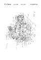
- FIG. 1is a perspective view of one preferred embodiment of an interactive play structure having features of the present invention
- FIG. 2is a perspective view of another preferred embodiment of an interactive play structure having features of the present invention.
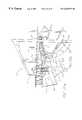
- FIG. 3is a schematic plan view of the interactive play structure of FIG. 1;
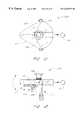
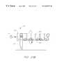
- FIG. 4is a detail plan view of the bucket-drop play zone of the interactive play structure of FIG. 1;
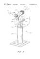
- FIGS. 5-7are perspective, side elevational and front elevational views, respectively, of a spring-loaded catapult accelerator having features of the present invention
- FIG. 8is a side elevational view of an alternative embodiment of a spring-loaded catapult accelerator having features of the present invention.
- FIGS. 9 and 10are side elevational and perspective views, respectively, of a counterweight catapult accelerator having features of the present invention.
- FIG. 11is a side elevational view of an alternative embodiment of a counterweight catapult accelerator having features of the present invention.
- FIGS. 12 and 13are top plan and side elevational views, respectively, of a crossbow accelerator having features of the present invention.
- FIGS. 14A and 14Bare top plan and side elevational views, respectively, of a flywheel accelerator having features in accordance with the present invention.
- FIG. 15is a perspective view of the flywheel accelerator of FIGS. 14A and 14B, showing one possible mode of operation by multiple play participants;
- FIGS. 16 and 17are top plan and side elevational views, respectively, of a flywheel accelerator having features of the present invention.
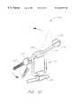
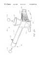
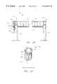
- FIGS. 18-20are perspective, side elevational and rear elevational views, respectively, of a spring-loaded plunger accelerator having features of the present invention
- FIG. 21is a perspective view of a cannon accelerator having features of the present invention.
- FIG. 22is a perspective view of a pump-gun accelerator having features of the present invention.
- FIG. 23is a perspective view of an alternative embodiment of a pump-gun accelerator having features of the present invention.
- FIG. 24is a perspective view of another alternative embodiment of a pump-gun accelerator having features of the present invention.
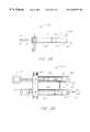
- FIGS. 25 and 26are top plan and side elevational views, respectively, of a dual-cylinder pump-gun accelerator having features of the present invention
- FIG. 27Ais a perspective view of a solenoid activated accelerator having features of the present invention.
- FIG. 27Bis a perspective view of an alternative embodiment of a solenoid activated accelerator having features of the present invention.
- FIG. 28is a perspective view of an interactive target having features of the present invention.
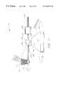
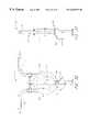
- FIGS. 29 and 30are front and right side elevational views, respectively, of a horizontal tube conveyor having features of the present invention.
- FIG. 31is a perspective view of the tube conveyor of FIGS. 29 and 30 showing one possible mode of operation by multiple play participants;
- FIGS. 32 and 33are front and right side elevational views, respectively, of a paddle wheel conveyor having features of the present invention.
- FIG. 34is a side elevational view of a plunger conveyor having features of the present invention.
- FIG. 35is a front elevational view of a vertical tube conveyor having features of the present invention.
- FIGS. 36 and 37are front and left side elevational views, respectively, of a vertical belt conveyor having features of the present invention.
- FIGS. 38 and 39are front and right side elevational views, respectively, of a flywheel conveyor having features of the present invention.
- FIG. 40is a side elevational view of an archimedes screw conveyor having features of the present invention.
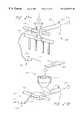
- FIG. 41is a perspective view of another embodiment of an interactive play structures having features of the present invention, provided in the theme of a medieval castle.
- FIGS. 1 and 2are perspective views of one preferred embodiment of an interactive play structure 100 having features and advantages in accordance with the present invention.
- the particular interactive play structure shownis provided in the theme of a futuristic city with thousands of soft foam balls providing a familiar and entertaining play medium.
- the present inventionmay be implemented in accordance with a wide variety of other possible embodiments and exciting play themes using any combination of familiar and fun play media. For example, a medieval castle, lost temple, military fort or fire station can each provide an exciting play theme for an interactive play structure having features and advantages as taught herein.
- Interactive play mediamay include, without limitation, such diverse items as tennis balls, rubber balls, beach balls, balloon balls, frisbees, foam darts/arrows, snow, mud, water-balloons, slime, as well as a variety of other fun and exciting play media well known to those skilled in the art.
- the play structure 100basically comprises a multi-level structure constructed using any one of an number of materials and construction techniques well known to those skilled in the art.
- the structure 100may be suitable for either outdoor or indoor use, as desired.
- the structure 100comprises a supporting framework 102 formed from a plurality of interconnected support members 126 , comprising columns, pylons, beams, connectors and the like.
- the support members 126may be formed from any combination of convenient materials having sufficient strength and durability for safely supporting multiple play participants 105 .
- plastic or PVC pipes, steel pipes, I-beams or channel beams, reinforced concrete beams/columns, and the likemay all be used to form the supporting framework 102 .
- a number of modular platforms 118are preferably supported between adjacent pylon or column members at various desired elevations with respect to ground level 116 . defining various play areas. As best illustrated in FIG. 3, the platforms are preferably of similar shape and dimension such they can be assembled in a modular fashion, as shown. Mating 4′ ⁇ 4′ square platforms 118 a and 4′ ⁇ 8′ rectangular platforms 118 b are used in the preferred embodiment of FIGS. 1-4 for purposes of providing a modular construction. Alternatively, it is envisioned that any one of a number of other suitable modular or non-modular shapes and sizes may be used, including without limitation, triangles, pentagons, hexagons and/or trapezoids.
- the modular construction as taught hereinallows a wide variety of play structures to be formed from a collection of standard support elements 126 and platforms 118 which may be interconnected on-site to create a play structure of virtually any desired shape, size, or height.
- Adjacent platforms 118are preferably staggered in elevation, as shown, such that play participants 105 can climb from one platform the next.
- Stairs 120 , climbing nets 108 , crawl tunnels 112 , or swinging bridges 122 and/or slides 110may also be provided to facilitate access to various elevated platforms 110 and play areas.
- Slides 110 originating from higher level platforms 118 of the play structure 100can quickly bring play participants 105 down to lower levels.
- one or more of the slides 110may terminate in a ball pit 111 , as shown, in order to increase excitement and protect play participants 105 from injury when exiting the slide 110 .
- optional decorative panels, railings 132 and/or roofing elements 130may be provided, as desired, to shade play participants 105 from the sun (for outdoor play structures), to prevent play participants from falling off the structure 100 , or to complement a particular desired theme of the play structure 100 .
- various roof elements 130 and railings 132are provided for added safety and to complement the theme of a futuristic city.
- Decorative panelsmay be formed of wood, fiberglass or other reinforced fiber, PVC, aluminum, steel or a variety of other suitable materials, as desired. Corrosion-resistant materials are preferred if the play structure 100 is to be used outdoors.
- PVCpolyvinylene
- steelaluminum
- Corrosion-resistant materialsare preferred if the play structure 100 is to be used outdoors.
- those skilled in the artwill readily appreciate that a wide variety of other decorative or thematic elements may be incorporated into the overall design of the play structure 100 in order to provide added safety and/or to help convey a particular desired play theme.
- conduits 124are provided throughout the framework 102 for transporting play media to and from the various play areas in the play structure 100 .
- the conduits 124may be formed from plastic or PVC pipes joined together using commercially available fittings, as is well known in the art.
- Conduits 124may also be formed from a wide variety of other suitable materials such as steel pipe, ceramic/clay pipe, or they may be formed as open channels and/or runners, as desired.
- conduits 124 or conduits 124 having different colors or shapesmay be used, as desired, to accommodate various sizes and shapes of balls or other play media 104 .
- twisted flexible hose conduits 128are used in various selected locations throughout the play structure 100 to help compliment the futuristic theme of the play structure 100 and to transport balls or other play media 104 between the various interconnected play areas. Play media 104 may be transported by use of pressurized air or other suitable means, as desired.
- Various participant-operated conveyorsmay also be employed to circulate balls or other play media 104 from one area of the structure 100 to another, as will be described in greater detail below.
- the supporting framework 102may be constructed substantially entirely of molded or contoured concrete, fiberglass or plastic, as desired.
- the supporting frameworkmay be constructed entirely or partially from conduits 124 , which also transport play media to and from various locations throughout the play structure 100 .
- FIGS. 1 and 2utilizes thousands of soft foam balls as an interactive play medium 104 . These may be manipulated by play participants using various interactive play elements to create desired effects. Soft foam balls, commonly known as NerfTM balls, are particularly preferred. These familiar balls are desirable for their texture and light weight as well as their attractiveness to young children who delight in handling them. Balls may range in size from approximately 1′′ to 12′′ in diameter or larger, as desired, and are preferable about 21 ⁇ 2′′ in diameter. Preferably, the balls are not so small as to present a choking hazard for young children. The majority of the balls may be the same size, or a mixture of ball sizes may be utilized, as desired.
- a few play elementsmay utilize balls of a relatively large diameter (about 12′′ or more). Certain play elements may use only certain sized balls, with filtering relays (not shown) in the conduits 124 permitting only certain sized balls to roll to certain play areas. A range of colors for the balls may also be used for visual appeal. Optionally, ball sizes and/or types may be color-coded as desired to indicate their use with particular play elements or in certain play zones and/or for facilitating their return to the proper areas when they are removed.
- suitable play media 104may include, without limitation, foam, plastic or rubber balls and similarly formed articles such as cubes, plates, discs, tubes, cones, rubber or foam bullets/arrows, the present invention not being limited to any particular preferred play media. These may be used alone or in combination with one another. For instance, flying discs, such as FrisbeesTM, may be flung from one location on the play structure 100 while other play participants shoot at the discs using foam balls or suction-cup arrows. Wet or semi-wet play mediums, such as slime-like materials, snow, mud, squirt guns and/or water balloons may also used, as desired, to cool and entertain play participants. Durable plastic or rubber play media are preferable in an outdoor play structure where environmental exposure may prematurely destroy or degrade the quality of certain play mediums such as foam balls.
- Various interactive play elementsare disposed in, on and/or around the play structure 100 to allow play participants 105 to create desired effects, as illustrated in FIGS. 1-4.
- Thesemay include interactive elements such as projectile accelerators, cannons, interactive targets, fountains, geysers, cranes, filter relays, and the like for amusing and entertaining play participants and/or for producing various desired visual, aural or tactile effects.
- Some interactive play elementsmay have immediate effects, while others may have delayed effects. Some play elements may produce local effects while others may produce remote effects.
- Each play participant 105or sometimes a group of play participants working together, must experiment with the various play elements and associated actuators in order to discover which ones operated in which sequence will create the desired effect(s). Once one group figures it out, they can use the resulting play effect to surprise and entertain other play participants. Yet other play participants will observe the activity and will attempt to also figure it out in order to turn the tables on the next group. Repeated play on a particular play element can increase the participants' skills in accurately producing desired effects or increasing the size or range of such effects.
- play participantscan compete with one another using the various play elements to see which participant or group of participants can create bigger, longer, more accurate or more spectacular effects.
- an interactive play element in the form of a geyser 138is shown.
- the geyser 138sprays a fountain of balls or other play media 104 into the air, scattering them about the play structure 100 and/or onto surrounding play participants 105 .
- a conduit subterranean(not shown) may be used to feed play media 104 to the geyser 138 from beneath the ground level 116 .
- Play media 104may be sprayed either in a continuous or timed intermittent manner, as desired, or by direct or indirect activation by play participants.
- a recess or basin 166surrounds the geyser 138 in order to collect the balls or other play media 104 .
- play media 104may be collected and maintained in a sump basin (not shown) beneath the ground level 116 . This may be periodically pressurized such that upon opening of a release valve, play media is shot upward under pressure.
- a series of pistonsmay be used to eject play media 104 positioned in corresponding cylinders. Again, the pistons may be timed or sequenced, as desired.
- a flexible fire hose 170 and nozzle 136provide another possible interactive play element which can be manipulated by a play participant 105 to selectively spray various play media 104 into the air or at other play participants 105 .
- a spherical, preferably clear, plastic relay 172acts as a trap and/or filter selectively feeding play media 104 into a pressurized tank 168 . This tank, in turn, provides play media 104 under pressure to the flexible hose 170 and nozzle 136 . Dramatic visual effects are created as multi-colored balls and/or other play media 104 bounce around the interior of the relay 172 and are sprayed out of the nozzle 136 .
- the relay 172may also be used to collect and/or filter play media 104 for further transmission along the various conduits 124 , 128 or to other play elements or conveyors as desired.
- An archimedes blaster 178(right-most foreground of FIG. 1) provides yet another possible interactive play element, which play participants 105 can selectively activate to cause balls or other play media 104 to be conveyed upwardly along a vertical cylinder 180 and out through a nozzle 182 at the top. Balls or other play media 104 are forced up through the archimedes blaster 178 via suitable means such as pressurized air flowing along a spiral path upward to the nozzle 182 . If desired, the blaster 178 may be configured such that play participants at higher levels of the play structure 100 can siphon off some or all of the play media 104 in the blaster 178 by manipulating various valves, gates or the like.
- the nozzle 182is rotatable so that play participants 105 can selectively direct the nozzle 182 at various targets, other play participants 105 or the giant baskets 150 , 152 , as desired.
- the nozzle 182may be pre-programmed to rotate at a predetermined speed, or it may be remotely controlled electro-mechanically by play participants 105 .
- various projectile acceleratorsmay be provided to allow play participants 105 to accelerate balls or other play media 104 from a basket or collection bin to impact a target or other unsuspecting play participants.
- an acceleratorBefore an accelerator can be activated, however, it may first be necessary to provide the required “ammunition” by filling a corresponding basket or collection bin with balls or other play media 104 of a particular suited size and shape. This may be done, for instance, by gathering play media in a bucket or by operating an adjacent play element, such as a conveyor, to fill the collection bin.
- other play participantsmay form a bucket brigade or use a rope and pulley system to hoist balls or other play media 104 from a lower collection basin to fill the ammunition basket supplying the corresponding accelerator or other play elements.
- Some play elementsmay provide “second order” effects in that they depend on at least one other play element to supply them with balls or other play media 104 . Yet other play elements may provide “third order” effects in that their operation depends on two or more other play elements operated either simultaneously or in succession. Higher-order effects and/or various combinations of multiple-order and/or delayed effects may also be used to amuse and entertain play participants as desired. Those skilled in the art will appreciate that the number, variety and combination of multiple-order or delayed effects producible in accordance with the present invention is virtually unlimited.
- Other interactive play elementsmay include, for example and without limitation, a pull-chain activated overhead reservoir for dumping balls or other play media 104 onto play participants, a tray or channel for allowing balls or other play media 104 to roll down onto a target or other play participants, a bucket conveyor for lifting balls or other play media 104 from a lower collection basin to an elevated container for supplying other play elements, and various interactive or projectile activated targets.
- a pull-chain activated overhead reservoirfor dumping balls or other play media 104 onto play participants
- a tray or channelfor allowing balls or other play media 104 to roll down onto a target or other play participants
- a bucket conveyorfor lifting balls or other play media 104 from a lower collection basin to an elevated container for supplying other play elements
- various interactive or projectile activated targetsmay include, for example and without limitation, a pull-chain activated overhead reservoir for dumping balls or other play media 104 onto play participants, a tray or channel for allowing balls or other play media 104 to roll down onto a target or other play participants
- a pair of giant tipping buckets or baskets 150 , 152are balanced on top of the play structure 100 , as shown.
- the giant tipping baskets 150 , 152are adapted to periodically spill thousands of foam balls or other play media 104 onto play participants 105 below, creating dramatic visual and tactile effects.
- Each basket 150 , 152is preferably about 25-100 feet tall and, more preferably, about 30 feet tall.
- Each basketis pivotably mounted on top of the play structure 100 , as shown, and is adapted to tip over, periodically spilling a load of thousands of balls or other play media 104 onto play participants 105 below.
- One or both of the giant baskets 150 , 152may operate as a delayed effect, whereby play participants cooperate or compete to fill or empty the giant baskets, and thereby induce or prevent their spilling. Again, the possibilities for multiple order or delayed effects are virtually unlimited.
- Each giant basket 150 , 152is pivotably mounted so as to be conditionally stable when empty or filled to less than fill capacity. In its stable condition, the pivot axis of each basket 150 , 152 is above the combined center of gravity of each basket 150 , 152 and the balls or other play media 104 contained in the basket. When the level in each basket reaches a certain predetermined point, however, the combined center of gravity of the basket and its contents becomes elevated above the pivot axis. This causes each basket 150 , 152 to become unstable and to eventually spill.
- the conditions for stability and the direction of spillingcan be controlled by selectively weighting each basket to slightly bias it forwards or backwards, as desired. Alternatively, each basket may be mounted slightly off-axis in order to bias it in a particular desired direction.
- each basket 150 , 152may be varied, as desired, to accommodate different size play structures and to convey a particular play theme.
- the size and capacity of the basketscan also be varied, as desired, to achieve various desired effects having benefits and advantages as taught herein.
- the baskets 150 , 152may be filled by balls or other play media 104 supplied by a pipe and spout 154 (left) or an archimedes screw conveyor 160 (right). Depending upon the desired effect, this flow of play media 104 may either be passive-continuous, passive-intermittent, or partially or fully active (i.e., controlled by play participants). For passive-continuous flow, the basket fills up and spills over at fairly regular intervals. Alternatively, play media 104 filling the basket may be intermittent or random such that spilling of the giant baskets 150 , 152 occurs at unpredictable intervals.
- the baskets 150 , 152may optionally be filled or emptied using a giant scoop 156 mounted on a crane 158 .
- the crane 158is selectively controlled by one or more play participants 105 to position the scoop 156 over a sump 430 (FIG. 4) or other source of play media 104 .
- the scoop 156may be manipulated to pick up a load of balls or other play media 104 and deliver them to either basket 150 , 152 .
- the scoop 156 and crane 158are preferably capable of lateral and vertical motion using motors and controls such as are well known to those skilled in the art.
- one or more rope-and-pulley bucket lifts 142may be used to help fill or empty one or both of the baskets 150 , 152 , as desired.
- the balls or other play media 104 contained in the baskets 150 , 152preferably falls onto deflection shields 162 , as shown in FIG. 1 .
- Thiscauses the play media 104 to bounce and disperse widely, creating dramatic visual and aural effects.
- the presence of the shields 162also mitigates the direct impact of play media 104 on play participants 105 .
- the size and shape of the deflection shields 162 , the angle of orientation, and the particular materials used to construct the deflection shieldsmay be varied to create particular desired effects. Sheet metal awnings have been found to provide adequate results for most applications.
- One or more optional openings 164may be provided in the deflection shields 162 , as shown, for allowing at least a portion of the spilling play media 104 to directly impact play participants 105 standing on a platform immediately below the opening.
- Such openings 164may either be fixed in size or they may be adjustable via a sliding door or similar device well known in the art.
- the openings 164are of sufficient size and shape to allow significant amounts of play media 104 to enter and bounce about the play structure 100 , but not so large as to allow injury to play participants 105 .
- a single round opening 164 having an open area of between about 2-8 square feetprovides an adequate compromise for most applications. Of course, larger or smaller openings having various other shapes and sizes may also be used, as desired.
- Optional bafflesmay also be provided in the path of the spilling play media through the opening 164 in order to mitigate the direct impact of such articles on play participants standing immediately below the opening.
- Tubes 298Charge Reservoir 299 Foot Pump 301 Loading Funnel 302 Gun Barrel 303 Bellows 304 Handle 312 Twin Barrels 313 O-Ring 314 Compression Chamber 315 Pistons 316 Piston Handle 321 Pneumatic Gun 322 Barrel 323 Loading Basket 324 Supply Conduit 325 Pneumatic Hose 326 Feed Line 327 Actuator Switch 328 PLC
- FIGS. 5-11three types of catapult accelerators are shown, generally corresponding to spring-loaded catapults 200 , 210 and counterweight catapults 220 , 220 ′, respectively.
- the spring-loaded catapult 200 of FIGS. 5-7may either be mounted to a rail 132 of the play structure 100 (FIGS. 1, 2 ) or to a pedestal 202 , as shown.
- a housing 201preferably formed of acrylic or other suitable material, is adapted to tilt and swivel about a base 203 .
- a loading tube 204 on the top of the housing 201allows a play participant to load the catapult 200 with balls or other suitable play media 104 .
- a lever arm 205is provided, as shown, and is adapted to be ratcheted back to cock a catapult arm 206 against a torsion spring 208 .
- the lever arm 205is joined to the catapult arm 206 by a common shaft 209 around which the torsion spring 208 is disposed.
- An adjustable force regulatoris provided, as shown, comprising a stop bar 207 slidably fixed along an adjustment slot.
- the stop bar 207determines the maximum cocking angle of the catapult arm 206 . This may be provided for purposes of safety and/or to allow calibration of the catapult by play participants for increased accuracy, as desired.
- the catapult 200is operated by loading one or more balls or other play media 104 into the loading tube 204 , pulling back the lever arm 205 and then releasing the lever arm 205 to propel the ball or other play media 104 in a desired direction.
- an optional ammunition clip(not shown) may be provided comprising an extended tube adapted to hold several balls or other play media 104 . This may be selectively attached to the loading tube 204 , as desired, so that reloading and launching may be performed in rapid succession by play participants 105 .
- a sliding tab or the likemay be mounted on the clip at the entry into the catapult to control the delivery of each ball or other play media into the housing 201 of the catapult 200 , as needed. In a first position, for instance, the tab may obstruct the flow of balls or other play media 104 into the catapult housing 201 . In a second position the tab may allow balls or other play media 104 to fall into place in the catapult housing 201 .
- a wide variety of other methods and devicesmay be used to supply balls or other play media 104 to the catapult 200 as will be apparent to those skilled in the art.
- FIG. 8illustrates an alternative embodiment of a spring-loaded catapult 210 particularly adapted for rail-mounting.
- a U-shaped bar 211serves as a fulcrum about which the catapult arm 212 is pivoted.
- a cup 213 on the upper end of the arm 212holds a ball or other play media 104 to be flung or catapulted.
- a tension spring 214is secured to the other end of the arm 212 to facilitate energy storage and release for operating the catapult 210 .
- FIGS. 9 and 10show a possible variation of the catapult of FIG. 10 wherein a counterweight 216 is mounted on a threaded portion 217 of the lower end of the arm 212 to provide energy storage and release for operating the catapult.
- a counterweight 216is mounted on a threaded portion 217 of the lower end of the arm 212 to provide energy storage and release for operating the catapult.
- the catapult 220 ′has a movable counterweight 222 mounted on a threaded portion 223 of the catapult arm 224 .
- the counterweight 222is formed from a dense material such as lead or steel in order to provide sufficient weight to store and release energy.
- a pedestal base 225 of the catapultis preferably adapted to be rotatable in the horizontal plane in accordance with conventional swivel designs so that the catapult may be aimed in any desired direction.
- the arm 224is mounted on a shaft 226 pivotably supported by bearings 228 . Alternatively, play participants may use their own weight to propel play media 104 by jumping on one end of a catapult arm.
- FIGS. 12 and 13show a crossbow or slingshot accelerator 230 .
- the crossbow 230comprises a housing 231 within which a resilient band 232 is disposed, as shown.
- the housing 231is preferably formed of a translucent plastic material such as acrylic so that the inner workings of the device may be viewed by play participants.
- the resilient band 232may be any type of suitable elastic or rubber band such as the type available under the name “Bungees.”
- the entire assemblyis preferably mounted on a rotatable support 233 secured to a rail or other portion of the play structure, as desired.
- a ball or other play media 104is fed into a loading chamber 236 provided on the top of the housing 231 .
- the resilient band 232is stretched in a horizontal plane using a suitable cocking mechanism 237 .
- a sliding handle 234may be pulled back to cock the crossbow 230 .
- the trigger 235may be depressed to release the band 232 , accelerating the ball or other play media 104 as the elastic band 232 contracts to its original shape.
- FIGS. 14A and 14Bshow an alternative embodiment of an interactive accelerator provided in the form of a flywheel accelerator 240 .
- a generator 239is actuated by one play participant by turning a wheel crank 241 .
- the generator 239is connected by electrical cables or a pneumatic conduit 242 to a corresponding electric or pneumatic motor (not shown) located within the housing 243 .
- the motorturns a pair of opposed flywheels 244 at one end of the housing 243 .
- the flywheels 244are separated by a distance approximately equal to or slightly smaller than the diameter of the play media 104 such that as the play media 104 enters the gap, the flywheels 244 propel the play media down the barrel 245 of the flywheel accelerator 240 and out the end thereof, as shown.
- any of the above-described accelerators or other interactive play elementsmay require the cooperative efforts of multiple play participants at multiple locations and/or levels of the play structure to produce a desired play effect.
- a play participant 105 at a distant location or elevationmay load play media 104 into a basket 246 or other receptacle. This may be connected by a conduit 124 to a loading tube 247 in order to provide ammunition to the flywheel accelerator 240 .
- Another play participant 105cranks the wheel 241 to generate power to run the accelerator 240 .
- a third play participantaims and fires the accelerator 240 by actuating a suitable trigger device. In this manner, multi-level interactive play is attained.
- an overhead hopper(not shown) may be used to collect play media 104 for use in the flywheel accelerator 240 .
- the hoppermay be fed by various conduits or conveyor systems of the play structure 100 , the hopper having an outlet for supplying play media to the basket 246 and/or other interactive play elements, as desired.
- the flywheel accelerator 250generally comprises a housing 259 mounted to a base 253 which is adapted to be pivotably mounted to a rail of the play structure.
- a flywheel 252is disposed within the housing for propelling play media 104 .
- Play participantsprovide energy to the flywheel 252 by turning a hand crank 257 which turns a drive-gear cluster 264 which, in turn, drives the flywheel 252 using a drive chain or belt.
- a bicycle-type derailleur 261is provided for allowing play participants to change the gear ratio between the hand crank 257 and the flywheel 252 in order to attain a range of desired flywheel speeds.
- a corresponding gear shifter 254is mounted on a handle 255 at a proximal end of the housing 259 and is operatively connected via a cable actuator 258 to the derailleur 261 in order to allow play participants to shift between gears as desired.
- balls or other play media 104are fed into the loading chamber 263 .
- the housing 259is formed such that the balls or play media 104 are guided into the barrel 256 adjacent the flywheel 252 .
- the flywheel 252engages the play media 104 propelling it down the barrel 256 .
- Play participantscan control the velocity and acceleration of play media by selectively controlling the speed of the flywheel 252 .
- An optional gunsight 262provides an aiming mechanism for increasing the accuracy of the flywheel accelerator 250 .
- FIGS. 18-20show a plunger-type accelerator 270 .
- the accelerator 270generally comprises a barrel 272 , preferably of a suitable translucent material such as acrylic, and a spring-loaded plunger 276 .
- the plunger 276has a distal end which is positioned near the entrance of the barrel 272 .
- a spring 277is positioned around a shaft 278 of the plunger 276 , as shown.
- the plunger shaft 278has a handle 279 on one end which is positioned outside the barrel 272 .
- a play participantpulls on the handle 279 to compress the spring 277 .
- the handle 279is released, the spring 277 expands, causing the plunger 276 to impact the ball or other play media 104 in the barrel 272 propelling it out the barrel 272 .
- the accelerator 270may be pedestal-mounted or rail-mounted as desired.
- a basket 271is preferably provided for holding balls or other play media 104 to be fed into the accelerator 270 .
- the basket 271is preferably mounted above the barrel 272 and to one side so that the balls or play media fall into the barrel 272 and the basket 271 does not obscure the line of sight of a play participant operating the accelerator 270 .
- a rotatable disk 273may be provided, as shown, having at least one opening for selectively admitting balls or other play media 104 into the loading tube 274 of the accelerator 270 .
- FIG. 21illustrates another embodiment of an interactive play element provided in the form of a pneumatic cannon accelerator 280 .
- the cannon accelerator 280basically comprises a barrel 283 mounted on a swivel base 284 .
- the cannon barrel 283is preferably formed of a suitable clear or translucent material such as acrylic or the like.
- One or more air bags or bladders 281are disposed around the cannon accelerator 280 , as shown, and are connected by flexible pneumatic hoses 282 to the barrel 283 of the cannon 280 . Suitable check valves are provided for each hose 282 to prevent back-flow of air into the bags 281 .
- play media 104in this case large foam balls are loaded into the open end of the barrel 283 .
- a play participantthen steps or jumps on one or more of the air bags 281 to inject air into the base of the barrel 283 , thereby expelling the play media 104 , as shown.
- FIG. 22illustrates a dual-piston pump-gun accelerator 290 generally comprising a barrel 292 , a charge reservoir 298 , and a pair of air pumps comprising pump pistons 295 operable within corresponding cylinders 296 .
- the pump-gun accelerator 290may be swivel-mounted on a rail 132 of the play structure, or it may be mounted on a separate pedestal or the like, as desired.
- An optional gun sight 262may be provided to assist in aiming the pump-gun accelerator 290 in a desired direction.
- the pistons 295are each adapted to be manually pumped by play participants, forcing air in the cylinders 296 into the charge reservoir 298 via flexible tubes 297 . Suitable check valves (not shown) are provided in the charge reservoir 298 or in the corresponding tubes 297 to prevent backflow of air.
- a play participantdepresses a trigger 291 adjacent the handle 294 . This opens a valve and releases air under pressure into the gun barrel 292 , thereby expelling the play media 104 .
- the pressure of the air in the charge reservoir 298 as well as the relative diameters of the play media 104 and barrel 292determine the exit speed of the projectile.
- the barrel 292is sized and shaped to have substantially the same diameter or slightly smaller diameter than the play media 104 in order to provide an adequate seal against the barrel 292 to prevent substantial air leakage around the play media 104 being propelled.
- the maximum pressure in the charge reservoir 298may be regulated by a relief valve or the like so as to maintain pressure at all times at safe levels.
- FIG. 23illustrates a variation of the pump-gun accelerator of FIG. 22 in which foot pumps 299 are used to provide compressed air to the charge reservoir 298 of the pump-gun 290 ′. All other material respects of the pump-gun accelerator 290 ′ are the same as that shown and described above in connection with FIG. 22, and, therefore, will not be repeated here.
- FIG. 24shows another embodiment of a pump-gun accelerator 300 having features and advantages in accordance with the present invention.
- the pump-gun accelerator 300is provided in the form of a “bellows gun” in which bellows 303 are compressed by a play participant to inject air into the barrel 302 to propel play media 104 .
- the bellows gun accelerator 300may be swivel-mounted to a rail 132 of the play structure or to a separate pedestal or base, as desired.
- play media 104is loaded into a loading funnel 301 which guides the play media 104 into the entrance of the barrel 302 .
- a play participantthen compresses the bellows 303 using handles 304 to force compressed air into the barrel 302 , thereby expelling the play media 104 from the barrel 302 of the pump-gun accelerator 300 , as shown.
- FIGS. 25 and 26illustrate another possible embodiment of an interactive play element provided in the form of a dual-chamber pump-gun accelerator 310 .
- the pump-gun accelerator 310basically comprises a pair of tubular barrels 312 in which are disposed corresponding pump pistons 315 .
- play media 104is loaded into a distal end of one or both barrels 312 .
- the play media 104is held in place by one or more O-rings 313 or the like, as shown.
- O-rings 313may be positioned at the distal ends 311 of the barrels 312 and may have an inner diameter slightly less than the diameter of the play media 104 , so that a seal forms between the O-ring 313 and the play media 104 substantially impeding the escape of air from each barrel 312 .
- a proximal portion of each barrel 312forms a compression chamber 314 between each piston 315 and the play media 104 .
- the pistons 315are each operated via a corresponding handle 316 located outside the barrel 312 .
- the barrel 312When play media 104 is inserted into the end of each barrel 312 , the barrel 312 is effectively plugged. That is, the size of play media 104 and the inner diameter of the barrel 312 are substantially equal or in slight interference.
- Optional rings 313keep the play media 104 from being sucked into the barrel 312 when the piston handle 316 is withdrawn to position “a”, as shown.
- the piston 315compresses the air between the piston 315 and the play media 104 , ultimately expelling the play media 104 out the end of the barrel 312 much in the same way as a cork gun expels a cork.
- FIGS. 27A and 27Billustrate another possible embodiment of an interactive play element in the form of a solenoid-activated pneumatic accelerator 320 , 320 ′.
- these accelerator devices 320 , 320 ′may be swivel-mounted to a rail of the play structure or to a separate pedestal or base, as desired.
- Each of the accelerators 320 , 320 ′utilizes a remote source of compressed air which is controlled by a switch-activated solenoid valve 321 or other suitable means which can be selectively activated by play participants to charge the barrel 322 with compressed air, thereby propelling play media 104 .
- a first pneumatic line 325provides compressed air from a source (not shown).
- a second pneumatic line 326 from the solenoid valve 321relays compressed air to the barrel 322 of the accelerator.
- the accelerator 320 shown in FIG. 27Ais essentially a one-shot device in which play media 104 must be loaded one article at a time and then fired.
- the accelerator 320 ′ shown in FIG. 27Bis a variation of that shown in FIG. 27A in which an automatic or repeating operation is achieved.
- play media 104may be automatically fed by a supply basket 323 which, in turn, is fed by a conduit 324 or by other play participants.
- the solenoid valve 321may be foot-operated or finger-operated, as desired, depending upon where the switch 327 is placed.
- PLCprogrammable logic controller
- PLC 328may comprise any one of a number of microchip devices well known in the art which are capable of being programmed to provide desired control of an associated device.
- acceleratorsmay be decorated or “themed” to convey a particular desired play theme or idea.
- acceleratorsmay be configured to simulate cannons, laser guns, machine guns or the like.
- Acceleratorsmay be mounted within a plexiglass hemisphere mounted under a floor of an upper level of the play structure so as to simulate a gunner's turret of a World War II bomber.
- Yet other acceleratorsmay be mounted on a moving vehicle, such as a train or steerable vehicle, capable of transporting one or more play participants. Roving vehicles such as an automobiles, buses tanks or space ships may also provide an exciting complement to a particular desired theme.
- projectile accelerators and the likemay be, and desirably are, provided throughout the various levels of the play structure in order to allow play participants to interact with one another using the various play media and interactive play elements.
- FIG. 28shows one preferred embodiment of an interactive target 500 having features and advantages of the present invention.
- the target 500basically comprises three target components: an upper target portion 503 , a middle target portion (“mega target”) 505 , and a lower target portion (“mega blower”) 507 , as shown.
- this targetgenerally comprises a target or support structure 509 disposed in, on or around the play structure 100 .
- a variety of funnel targets 511 , aperture targets 513 , spinners 515 , and the likeare mounted on the support structure 509 , as shown. Play participants activate the targets by causing a projectile to enter the open areas of the funnel or aperture targets 511 , 513 or to impinge upon the paddle surfaces of the spinner targets 515 .
- the funnel targets 511are arranged so that play media 104 entering the funnels 511 exits downwardly onto the spinners 515 .
- a play participantmanages to get play media 104 into the funnel target 511 it drains downward onto the spinning target 515 causing it to spin as the play media 104 impinges upon one or more paddles of the spinner 515 .
- Other targets 516 and 517are arranged along a conduit 519 , as shown, and operate to open or close valves 521 or other devices which release play media 104 from the conduit 519 into various ball drops 523 , 525 , 527 . Ball drop 523 releases play media 104 substantially straight downward as shown.
- Ball drop 525releases play media 104 down a barrel impinging a suspended conical impacting surface 529 which scatters play media within a 360° radius from the ball drop 525 .
- Ball drop 527allows play media 104 to flow into a flexible conduit 531 which may be controlled remotely such as by electromechanical actuators.
- Target 517is actuated if play media is caused to land on top of the funnel-shaped entrance and drains down into the conduit 519 .
- a sensor or other mechanismmay sense the entry of play media 104 and trigger one or more other effects as desired.
- the nature of the effects, duration and number of elements involvedmay vary depending upon the difficulty of actuating the various associated targets. For example, targets that are very difficult to hit may produce more dramatic effects so as to encourage play participants to actuate those effects by hitting the appropriate targets in the appropriate order. Various sound effects, flashing lights and other related effects may add to the excitement or assist play participants by informing them which targets need to be hit in which order to produce the desired effects. In this manner, play participants cooperate to activate the targets in the desired order to create the desired play effect. As a reward for activating a major play effect, play media may be released from a central chamber to yet other play devices to increase the level of excitement in the play structure. Alternatively, interactive play elements may change from manual loading to automatic or semi-automatic operation as a reward for actuating certain targets. This, in turn, may assist play participants to activate even further targets to achieve the next level of reward.
- the intermediate target portion 505 or “mega target”is provided roughly intermediate the upper target 503 and the lower target 507 .
- the intermediate target 505is suspended by wires 551 hanging from the upper target or other support structure as needed.
- the target structure 503may be cantilever-mounted or supported in any one of a number of other ways well known to those of skill in the art.
- the mega target 505includes a plurality of pneumatically actuated accelerators 553 which are adapted to propel play media 104 into the air or back at play participants in response to one or more of the targets 555 , 557 , 559 , 561 , or 563 being actuated.
- the targets 555may be of a type that are switch or sensor activated such that when a projectile contacts the target surface, a switch is closed or opened to actuate an adjacent play effect such as one of the pneumatic accelerators 553 .
- the targets 561may be provided in the form of feed cones such that when play media enters the target 561 it flows down through a line 562 and is automatically shot out of one of the corresponding accelerators 553 .
- Spinner targets 557may be activated by causing a projectile to contact a paddle surface of the spinner target 557 . This in turn, may activate any one of a number of other effects on the interactive mega target 500 or any of a variety of other interactive play elements or play effects disposed throughout the play structure.
- the accelerators 553are mounted such that they randomly swivel up and down and/or side to side so that the projectile path of play media 104 exiting each accelerator 553 is unpredictable. This adds to the level of excitement in and around the interactive target 500 .
- a cylindrical or donut-shaped truss 565provides a secure platform for mounting the various targets and accelerators.
- a major interactive target effectis actuated, for example, when play media enters the target 513 and flows downward through the center body of the upper target exiting the nozzle 533 into the cone-shaped funnel 567 of the mega target and down through the exit nozzle 569 .
- Thismay trigger a wide variety of different effects including interactive effects, bells, sounds, lights, whistles, and the like similar to a jackpot on a slot machine or pinball machine.
- the target 513is preferably adjusted or selected so as to provide a certain degree of difficulty in actuating the target so that the target effects will be fairly uncommon and, therefore, desirable.
- the lower target 507is in the form of a “mega blower” comprising a disk-shaped or donut-shaped truss assembly 591 supporting a fan 593 .
- the fanhas one or more rotating fan blades (not shown) enveloped in a cone-shaped protective shroud 595 .
- the fanmay be powered by play participants or an external energy source, as desired.
- the shroud 595may be in the form of a wire mesh or similar material that admits air but prevents fingers and arms from entering the fan area.
- the mega blower 507blows a jet of air upward so as to entrap or entrain various lightweight play media 104 as shown. These may include small foam balls or larger size foam balls, balloon balls, or beach balls, as desired.
- various devicesare preferably provided to collect and transport play media in and around the play structure. These may include, for example, passive collection and/or transportation devices, such as collection basins, channels and/or troughs, or they may include active or interactive collection and transportation devices.
- passive collection and/or transportation devicessuch as collection basins, channels and/or troughs
- active or interactive collection and transportation devicesmay include, for example, passive collection and/or transportation devices, such as collection basins, channels and/or troughs.
- Various conveyor systemsare disclosed and described herein by way of illustration only. Those skilled in the art will readily appreciate that a wide variety of other collection and/or transportation devices may be used while still enjoying the advantages and benefits of the present invention as taught herein.
- FIGS. 29-31illustrate one possible embodiment of an interactive conveyor device provided in the form of a horizontal tube conveyor 330 .
- the tube conveyor 330basically comprises a hollow tube 331 , preferably formed of a suitable clear or translucent material such as acrylic.
- a hand crank 336 and gears 337 , 338are provided for rotating the tube 331 .
- the tube 331preferably has spiral ridges 345 or the like formed on the inner surface thereof for moving play media 104 axially along the tube 331 . Play media is transported across a predetermined horizontal distance as the tube is rotated in a desired direction.
- the tube 331is rotatably supported at either end by a pair of base members 333 , 335 .
- Play media 104may be fed into either end of the tube and the tube may be rotated by play participants to transport play media in a desired direction.
- a crank 336is provided at one end 332 of the tube conveyor 330 for driving a gear 337 which mates with a toothed portion 338 of the tube 331 .
- a tube conveyor 330 ′may be rotated by a belt which is driven by a remotely located stationary bicycle 339 which may be on the same or a different level.
- a shaft 341is driven by a wheel of the stationary bicycle 339 , as shown.
- the shaftdrives a first belt-wheel 342 which drives second belt-wheel 344 , which turns the tube 331 .
- a play participant 105 on the bicycle 339causes the tube 331 to rotate.
- the bicycle 339may be positioned as near or as far from the tube conveyor 330 ′ as desired.
- a treadmillnot shown
- any other type of device for producing energy from human effortmay be substituted for the bicycle 339 or hand crank 336 , as desired.
- FIGS. 32 and 33show another type of interactive conveyor device in the form of a paddle wheel conveyor 350 .
- the paddle wheel conveyorbasically comprises a housing 353 within which is disposed a rotatable paddle wheel 354 .
- a crank 355is adapted to allow play participants to impart a desired amount of rotational speed to the paddle wheel 354 .
- a step-up gear ratiois provided such that a relatively slow rotational speed of the crank 355 causes relatively fast rotational speed of the paddle wheel 354 such that the paddle wheel 354 rotates fast enough to impart sufficient energy to the play media 104 to propel it up into the exit tube 357 .
- the paddle wheel 354accelerates the play media 104 such that the centrifugal force exerted by the play media 104 when it reaches a point 358 between the paddle wheel 354 and the exit tube 357 , is adequate to lift the play media 104 up into the exit tube 357 .
- the exit tube 357may be negatively pressurized relative to the inlet tube 351 , as desired, to prevent play media 104 from falling back into the housing 353 .
- two or more centrifugal conveyors 350may be connected together, driven by the same crank(s), in order to provide parallel propulsion of play media 104 between various portions of the play structure.
- FIG. 34illustrates another possible interactive conveyor device provided in the form of a plunger conveyor 360 .
- a tube housing 364is provided having an opening at the top for admitting play media 104 , and a plunger 367 for compacting the play media into a conveyor tube 368 , as shown.
- Play media 104exits the conveyor tube 368 into a collection basket 361 or other receptacle as desired. This may be on the same or a different level of the play structure, as desired.
- the plunger conveyor 360may be rail mounted or it may be mounted to a floor stand 362 , as shown.
- play participantsfill a feed basket 363 on top of a housing 364 with play media 104 .
- a play participantthen pulls out the handle 365 which is connected to a shaft 366 which operates the plunger 367 .
- the plunger 367With the plunger 367 retracted, play media drops into the housing 364 .
- the plunger 367forces the play media 104 into the tube 368 .
- Thismay be either a fixed or flexible tube, as desired.
- an optional clip or ringmay be mounted on the inner diameter of the tube 368 adjacent the housing 364 to prevent backflow of play media 104 into the housing 364 .
- FIG. 35illustrates another possible embodiment of an interactive conveyor device provided in the form of a vertical tube conveyor 370 .
- the vertical tube conveyor 370basically comprises a hollow vertical tube 378 , preferably formed of a suitable clear or translucent material, having a rope or cable 371 passing axially therethrough.
- the rope 371extends vertically upward through the tube 378 and around upper and lower pulleys 372 , 373 to form a closed loop.
- the rope 371may be pulled downward by one or more play participants to cause the rope 371 to move upward through the tube 378 .
- play media 104 in the supply basket or hopper 376is fictionally engaged between the rope 371 and the inner wall of the tube 378 such that the play media rolls up upward through the tube 378 , as shown.
- play media 104flows out into the collection basket 377 . Play participants can watch as play media is carried up the tube 378 .
- FIGS. 36 and 37illustrate one possible variation of the vertical tube conveyor 370 shown in FIG. 35 .
- a conveyor deviceis provided in the form of a vertical belt conveyor 380 .
- the vertical belt conveyor 380generally comprises a housing 384 within which is disposed a vertical conveyor belt system extending between a pair of belt-wheels 387 .
- a crank handle 386is adapted to be turned by a play participant to cause the belt 388 to move in a desired direction.
- the belt 388 and housing 384are separated by a distance at least slightly smaller than the diameter of the play media 104 (in this case preferably foam or rubber balls). As a play participant turns the crank 386 , play media flows down a slanted floor 383 into an opening 382 provided in the housing 384 .
- the belt 388moves relative to the inner wall of the housing 384 trapping play media 104 between the belt 388 and the inner surface of the housing. This causes the play media 104 to roll upward through the housing against the moving belt 388 .
- an outlet opening 390is provided allowing play media to exit the housing 384 into an adjacent conduit, onto other play participants or back into the collection basket 381 which supplies the vertical belt conveyor 380 , as desired.
- FIGS. 38 and 39illustrate another possible interactive conveyor device provided in the form of a flywheel conveyor 400 .
- This conveyorutilizes a stationary bicycle 401 to rotate a flywheel 402 to a relatively high velocity such that it flips or flings play media 104 from a lower collection basket 408 into an elevated collection basket 403 .
- the flywheel 402is mounted on a common shaft 399 with the drive wheel of the stationary bicycle 401 .
- the shaft 399is driven by a chain drive system which includes a crank gear 406 , pedals 407 and a chain 405 .
- the flywheel 402is disposed within an elongated arcuate housing 409 , which provides a deflection path for play media flung from the flywheel 402 .
- the housingis formed at least partially of a clear or translucent plastic material so that play participants can observe the inner workings of the conveyor and play media 104 impacting and being flung from the flywheel 402 .
- the stationary bicycle 401may be provided with a variable gear system in order to allow play participants to attain various desired rotational speeds of the flywheel 402 and, therefore, rate of conveyor operation.
- FIG. 40illustrates another possible interactive conveyor device provided in the form of an archimedes screw conveyor 420 .
- the archimedes screw conveyor 420comprises an outer tube 421 rotatably supported by a plurality of roller bearings 426 .
- the tube 421is inclined at an angle of between about 30 and 60 degrees and has at least one helical lip or groove 422 formed on the inner surface thereof, as shown.
- the helical lip 422is formed such that when the tube 421 is rotated in a preselected direction, play media 104 from a lower basket 423 is conveyed up the length of the tube 421 exiting into an upper basket 425 .
- the tubeis rotated by play participants using a suitable expedient, such as a hand crank, belt drive, stationary bicycle, tread mill or the like as described herein.
- a crank 429may be adapted to turn a chain 428 or a series of gears or other drive mechanisms to rotate the tube 421 .
- the archimedes conveyormay be powered by a separate power source such as an electric motor or the like.
- the base of the archimedes screw conveyormay be rotatable in order to allow play participants to direct the output thereof.
- the various conveyor systems described abovemay be linked with one another or with other passive, active, semi-active or interactive conveyor systems so as to extend over several locations or levels of the play structure.
- the archimedes screw 420may form but one part of a more complex interactive play effect that is comprised of a sequence of smaller effects, each operated by a number of different play participants cooperating together to create an overall desired effect.
- Passive collection devices and conveyorsmay also be used, such as collection basins, troughs, conveyor belts, pneumatic conduits, continuous belt elevators and the like, to collect and transport play media to the various areas of the play structure as needed.
- drains and traps 140may be provided at various locations in and around the play structure 100 to help collect spent play media 104 .
- Collection lines 432may be provided above or below the ground level to route play media to other collection areas such as sump 430 .
- Play mediamay also be collected by a gently sloping perimeter gutter (not shown).
- a vacuum(not shown) may also be used to suck up play media and deliver it to a central accumulator.
- a control valve manifold(not shown) may be used to control the pressure and flow of air and play media in the various pneumatic conduits 124 of the play structure 100 and direct the number and size of play media 104 going to each connecting conduit and/or play element.
- Various gates and valvesmay be provided throughout the play structure to allow play participants to control the flow of play media to the various areas of the play stricture and to various effects.
- Cleaning and/or decontamination devicesmay also be provided for continuously or periodically cleaning play media circulated throughout the play structure. These may be passive or interactive, as desired.
- a chlorine bathmay be provided in combination with brush or ultrasonic cleaner in order to remove dirt and contaminants from spent play media, as needed.
- Play participantsmay turn a crank or other input device to operate an interactive cleaner and watch as balls or other play media 104 slosh about the cleaner housing, which is preferably formed of a clear material. Drying of play media 104 may also be provided in a similar manner, as desired.
- the play structure 100also preferably incorporates a number of other conventional (passive) play elements, such as climbing nets 108 , crawl tunnels 112 , swinging bridges 122 , slides 110 , and the like as shown in FIGS. 1-3. These provide entertaining physical challenges and allow play participants to safely negotiate their way through the various levels and platforms 118 of the play structure 100 .
- Crawl tunnels 112may be constructed of any variety of suitable materials such as clear plastic or fiberglass, or, more preferably, they may be constructed of a soft webbing or net material. Tunnels 112 may terminate next to a slide 110 or they may lead to another area of the structure 100 , as desired.
- enclosure panels and/or safety nettingare preferably provided around the various entrances to the slides 110 to prevent play participants 105 from falling off the play structure 100 or to complement a particular theme.
- Swinging bridges 122allow play participants to traverse between the right and left sides, or front and rear, of the play structure 100 .
- the use of hand rails 132 , enclosure panels, and non-slip surfacesprovides added safety in order to protect play participants 105 from possible injury.
- Slides 110may be provided at the front, rear, and/or sides of the play structure 100 and may be straight, curved, or spiral-shaped, as desired. They may also be enclosed and tube-like or open and exposed to flying play media, as desired. Alternatively, those skilled in the art will readily appreciate that the size, number, and location of the various slides 110 can be varied, as desired, while still enjoying the benefits and advantages of the present invention.
- Ball pits 111may also be provided at various locations throughout the play structure. Play participants 105 can slide into the ball pit 111 as shown in FIG. 1 or they can jump into the pit 111 from a raised platform. Ball pits 111 may be of varying depths, as desired, taking into consideration the size of the play participants and the need to facilitate exiting of the pit 111 by play participants 105 . Those skilled in the art will readily appreciate that a wide variety of other passive play elements, such as funny mirrors, rotating tunnels, trampolines, climbing bars, swings, etc. may all be used while still enjoying the features and advantages as of the present invention as taught herein.
- FIG. 41illustrates another embodiment of an interactive play structure 107 provided in the form of a medieval castle having catapults, mortars, cross-bows and the like.
- the structureincludes a central castle 440 having a tower 442 disposed in a “war zone” area.
- Such a play structuremay include, for example, a series of crossbows or catapults for use with moving or fixed targets and can be adapted for individual or team play.
Landscapes
- Health & Medical Sciences (AREA)
- General Health & Medical Sciences (AREA)
- Physical Education & Sports Medicine (AREA)
- Engineering & Computer Science (AREA)
- Multimedia (AREA)
- Toys (AREA)
- Pinball Game Machines (AREA)
- Management, Administration, Business Operations System, And Electronic Commerce (AREA)
Abstract
Description
| TABLE 1 | |
| Ref. | |
| 100 | |
| 102 | |
| 104 | |
| 105 | |
| 107 | |
| 108 | |
| 110 | Slide |
| 111 | |
| 112 | |
| 116 | |
| 118 | |
| 120 | |
| 122 | |
| 124 | |
| 126 | |
| 128 | |
| 130 | |
| 132 | |
| 134 | |
| 136 | |
| 137 | |
| 138 | |
| 139 | |
| 140 | |
| 142 | |
| 150 | Giant Basket (Left) |
| 152 | Giant Basket (Right) |
| 154 | |
| 156 | |
| 158 | |
| 160 | |
| 162 | |
| 164 | Shied |
| 166 | |
| 168 | |
| 170 | |
| 172 | |
| 174 | Actuator |
| 178 | |
| 182 | |
| 184 | |
| 200 | Spring Catapult |
| 210 | Counterweight Catapult |
| 220 | Basket Catapult |
| 230 | |
| 240 | |
| 250 | |
| 270 | |
| 280 | |
| 290 | Compressed |
| 300 | |
| 320 | |
| 420 | |
| 430 | |
| 432 | Collection Lines |
| TABLE 2 | |||
| Ref. | |||
| 200 | Spring-Catapult | ||
| 201 | |||
| 202 | |||
| 203 | |||
| 204 | |||
| 205 | |||
| 206 | Catapult | ||
| 207 | |||
| 208 | |||
| 209 | |||
| 214 | |||
| 220 | Counterweight Catapult | ||
| 211 | |||
| 212 | Catapult | ||
| 213 | Cup | ||
| 216 | |||
| 217 | Threaded | ||
| 218 | |||
| 220 | Basket Catapult | ||
| 221 | |||
| 222 | |||
| 223 | Threaded | ||
| 224 | Catapult | ||
| 225 | |||
| 226 | |||
| 228 | |||
| 230 | |||
| 231 | |||
| 232 | |||
| 233 | |||
| 234 | |||
| 235 | |||
| 236 | |||
| 237 | |||
| 240, 250 | |||
| 241 | |||
| 242 | |||
| 243 | |||
| 244, 252 | |||
| 245 | |||
| 246 | |||
| 247 | |||
| 253 | |||
| 254 | |||
| 255 | |||
| 256 | |||
| 257 | |||
| 258 | |||
| 259 | |||
| 260 | |||
| 261 | Derailleur | ||
| 262 | |||
| 270 | |||
| 271 | Basket | ||
| 272 | |||
| 273 | |||
| 274 | |||
| 276 | Plunger | ||
| 277 | |||
| 278 | |||
| 279 | |||
| 280 | |||
| 281 | |||
| 282 | |||
| 283 | |||
| 284 | Swivel Base | ||
| Pump, | |||
| 291 | |||
| 292 | |||
| 293 | |||
| 294 | |||
| 295 | |||
| 296 | |||
| 297 | Flex. | ||
| 298 | |||
| 299 | |||
| 301 | |||
| 302 | |||
| 303 | |||
| 304 | |||
| 312 | Twin Barrels | ||
| 313 | O- | ||
| 314 | |||
| 315 | |||
| 316 | |||
| 321 | |||
| 322 | |||
| 323 | |||
| 324 | |||
| 325 | |||
| 326 | |||
| 327 | |||
| 328 | PLC | ||
| TABLE 3 | |||
| Ref. | Description | ||
| 500 | |||
| 503 | |||
| 505 | |||
| 507 | |||
| 509 | |||
| 511 | |||
| 513 | |||
| 515 | |||
| 516, 518 | |||
| 519 | Conduit | ||
| 521-525 | |||
| 527 | |||
| 533 | |||
| 529 | |||
| 551 | |||
| 553 | |||
| 555 | |||
| 557 | |||
| 559 | |||
| 561 | |||
| 562 | Feed Tubes | ||
| 563 | |||
| 565 | |||
| 567 | |||
| 569 | |||
| 591 | |||
| 593 | |||
| 595 | Fan Shroud | ||
| TABLE 4 | |||
| Ref. | |||
| 330 | Horiz. | ||
| 331 | |||
| 333, 355 | |||
| 336 | Crank Handle | ||
| 337 | |||
| 338 | |||
| 339 | |||
| 341 | |||
| 342 | |||
| 343 | |||
| 344 | |||
| 345 | |||
| 350 | |||
| 351 | |||
| 353 | |||
| 354 | |||
| 355 | |||
| 357 | |||
| 358 | |||
| 360 | |||
| 361 | |||
| 362 | |||
| 363 | |||
| 364 | |||
| 365 | Handle | ||
| 366 | |||
| 367 | |||
| 368 | |||
| 370 | |||
| 371 | |||
| 372 | |||
| 373 | |||
| 376 | |||
| 377 | |||
| 378 | |||
| 380 | |||
| 381 | |||
| 382 | |||
| 383 | |||
| 384 | |||
| 386 | Crank Handle | ||
| 387 | |||
| 388 | |||
| 390 | |||
| 400 | |||
| 401 | Exercycle | ||
| 402 | |||
| 403 | |||
| 405 | |||
| 406 | |||
| 407 | |||
| 408 | |||
| 409 | |||
| 420 | |||
| 421 | |||
| 422 | |||
| 423 | |||
| 424 | |||
| 425 | |||
| 426 | |||
| 427 | |||
| 428 | |||
| 429 | Hand Crank | ||
Claims (29)
Priority Applications (1)
| Application Number | Priority Date | Filing Date | Title |
|---|---|---|---|
| US09/133,505US6283871B1 (en) | 1989-11-20 | 1998-08-12 | Participatory play structure having discrete play articles |
Applications Claiming Priority (8)
| Application Number | Priority Date | Filing Date | Title |
|---|---|---|---|
| US43822089A | 1989-11-20 | 1989-11-20 | |
| US07/604,946US5194048A (en) | 1989-11-20 | 1990-10-29 | Participatory water play apparatus |
| US08/025,143US5405294A (en) | 1989-11-20 | 1993-03-02 | Participatory water play apparatus |
| US33337394A | 1994-12-16 | 1994-12-16 | |
| US08/409,133US5820471A (en) | 1989-11-20 | 1995-03-23 | Participatory water play system |
| US260595P | 1995-08-21 | 1995-08-21 | |
| US08/621,173US5853332A (en) | 1995-08-21 | 1996-03-21 | Participatory play structure having discrete play articles |
| US09/133,505US6283871B1 (en) | 1989-11-20 | 1998-08-12 | Participatory play structure having discrete play articles |
Related Parent Applications (1)
| Application Number | Title | Priority Date | Filing Date |
|---|---|---|---|
| US08/621,173ContinuationUS5853332A (en) | 1989-11-20 | 1996-03-21 | Participatory play structure having discrete play articles |
Publications (1)
| Publication Number | Publication Date |
|---|---|
| US6283871B1true US6283871B1 (en) | 2001-09-04 |
Family
ID=26670609
Family Applications (2)
| Application Number | Title | Priority Date | Filing Date |
|---|---|---|---|
| US08/621,173Expired - LifetimeUS5853332A (en) | 1989-11-20 | 1996-03-21 | Participatory play structure having discrete play articles |
| US09/133,505Expired - LifetimeUS6283871B1 (en) | 1989-11-20 | 1998-08-12 | Participatory play structure having discrete play articles |
Family Applications Before (1)
| Application Number | Title | Priority Date | Filing Date |
|---|---|---|---|
| US08/621,173Expired - LifetimeUS5853332A (en) | 1989-11-20 | 1996-03-21 | Participatory play structure having discrete play articles |
Country Status (10)
| Country | Link |
|---|---|
| US (2) | US5853332A (en) |
| EP (1) | EP0850096B1 (en) |
| JP (1) | JPH11504837A (en) |
| KR (1) | KR100267840B1 (en) |
| CN (1) | CN1199351A (en) |
| AU (1) | AU712615B2 (en) |
| BR (1) | BR9610425A (en) |
| CA (1) | CA2230066C (en) |
| PL (1) | PL182315B1 (en) |
| WO (1) | WO1997006867A2 (en) |
Cited By (44)
| Publication number | Priority date | Publication date | Assignee | Title |
|---|---|---|---|---|
| US20040033833A1 (en)* | 2002-03-25 | 2004-02-19 | Briggs Rick A. | Interactive redemption game |
| US20040092311A1 (en)* | 2002-04-05 | 2004-05-13 | Weston Denise Chapman | Live-action interactive adventure game |
| US6761637B2 (en) | 2000-02-22 | 2004-07-13 | Creative Kingdoms, Llc | Method of game play using RFID tracking device |
| US20040198517A1 (en)* | 2002-08-01 | 2004-10-07 | Briggs Rick A. | Interactive water attraction and quest game |
| US20040198519A1 (en)* | 2002-11-18 | 2004-10-07 | Kenneth Schober | Interactive laser amusement system |
| US20040204240A1 (en)* | 2000-02-22 | 2004-10-14 | Barney Jonathan A. | Magical wand and interactive play experience |
| US20050074277A1 (en)* | 2003-09-19 | 2005-04-07 | Hasbro, Inc. | Toy gun for launching a foam projectile |
| US20050101417A1 (en)* | 2003-11-06 | 2005-05-12 | Scott Hamons | Scoring system for a ball activity area |
| US7060002B1 (en)* | 2002-10-21 | 2006-06-13 | Boehme Theodore F | Physical fitness course |
| US20060229134A1 (en)* | 2005-03-17 | 2006-10-12 | Briggs Rick A | Interactive challenge game systems and methods |
| US20060234601A1 (en)* | 2000-10-20 | 2006-10-19 | Weston Denise C | Children's toy with wireless tag/transponder |
| US20060258471A1 (en)* | 2002-08-01 | 2006-11-16 | Briggs Rick A | Interactive water attraction and quest game |
| US20070020606A1 (en)* | 2005-07-19 | 2007-01-25 | Knight J B | Systems and methods for retail selling that integrates children's recreation, retail selling, and company advertising and sponsorship |
| US20070051038A1 (en)* | 2005-04-20 | 2007-03-08 | Henry Jeffery W | Tree with covering apparatus |
| US20070066396A1 (en)* | 2002-04-05 | 2007-03-22 | Denise Chapman Weston | Retail methods for providing an interactive product to a consumer |
| US20070087849A1 (en)* | 2005-09-02 | 2007-04-19 | Henry Jeffery W | Amusement water rides involving exercise circuits |
| US20070087852A1 (en)* | 2005-09-02 | 2007-04-19 | Henry Jeffery W | Methods and systems for self-contained floating marine parks |
| US7445550B2 (en) | 2000-02-22 | 2008-11-04 | Creative Kingdoms, Llc | Magical wand and interactive play experience |
| US20090009294A1 (en)* | 2007-07-05 | 2009-01-08 | Kupstas Tod A | Method and system for the implementation of identification data devices in theme parks |
| US20090111074A1 (en)* | 2007-10-30 | 2009-04-30 | Shahal Shay | Computerized content-enriched environment for children |
| US7572191B2 (en) | 2006-04-14 | 2009-08-11 | Creative Kingdoms, Llc | Interactive water play apparatus and methods |
| US7597630B2 (en) | 2004-11-24 | 2009-10-06 | Water Ride Concepts, Inc. | Water amusement park conveyors |
| US7614958B2 (en) | 2001-11-16 | 2009-11-10 | Creative Kingdoms, Llc | Interactive quest game |
| US7727077B2 (en) | 2005-08-03 | 2010-06-01 | Water Ride Concepts, Inc. | Water amusement park water channel flow system |
| US7740542B2 (en) | 2000-09-11 | 2010-06-22 | Water Ride Concepts, Inc. | Water amusement method |
| US7749089B1 (en) | 1999-02-26 | 2010-07-06 | Creative Kingdoms, Llc | Multi-media interactive play system |
| US7762899B2 (en) | 2005-08-30 | 2010-07-27 | Water Ride Concepts, Inc. | Water amusement park conveyor support elements |
| US7762900B2 (en) | 2006-03-14 | 2010-07-27 | Water Ride Concepts, Inc. | Method and system of positionable covers for water amusement parks |
| US7775895B2 (en) | 2005-08-03 | 2010-08-17 | Water Ride Concepts, Inc. | Water amusement park water channel and adjustable flow controller |
| US7775894B2 (en) | 2003-10-24 | 2010-08-17 | Water Ride Concepts, Inc. | Method and system of participant identifiers for water amusement parks |
| US7815514B2 (en) | 2005-08-30 | 2010-10-19 | Water Ride Concepts, Inc. | Water amusement park conveyor barriers |
| US7857704B2 (en) | 2005-09-15 | 2010-12-28 | Water Ride Concepts, Inc. | Amusement water rides involving games of chance |
| US7878905B2 (en) | 2000-02-22 | 2011-02-01 | Creative Kingdoms, Llc | Multi-layered interactive play experience |
| US8079916B2 (en) | 2008-12-18 | 2011-12-20 | Water Ride Concepts, Inc. | Themed amusement river ride system |
| US8096892B2 (en) | 2002-03-25 | 2012-01-17 | Water Ride Concepts, Inc. | Control system for water amusement devices |
| US8282497B2 (en) | 2005-08-30 | 2012-10-09 | Water Ride Concepts, Inc. | Modular water amusement park conveyors |
| US8900074B1 (en) | 2013-07-25 | 2014-12-02 | Kevin F. Johnson | Reconfigurable sports training device |
| WO2015188204A1 (en)* | 2014-06-09 | 2015-12-17 | Shkodra Shemsedin | Equipment for games and celebrations; shooter - host - re-shooter in altitude and in distance of balls or of other objects |
| US9446319B2 (en) | 2003-03-25 | 2016-09-20 | Mq Gaming, Llc | Interactive gaming toy |
| US9480913B2 (en) | 2011-01-26 | 2016-11-01 | WhitewaterWest Industries Ltd. | Interactive entertainment using a mobile device with object tagging and/or hyperlinking |
| US10518121B2 (en)* | 2015-11-16 | 2019-12-31 | Metalco Active S.R.L. | Reversibly installable modular fitness area |
| US10576388B2 (en) | 2016-11-14 | 2020-03-03 | Whitewater West Industries Ltd. | Play center using structural monoliths for water delivery capabilities |
| US10758831B2 (en) | 2014-11-17 | 2020-09-01 | Whitewater West Industries Ltd. | Interactive play center with interactive elements and consequence elements |
| US20210387036A1 (en)* | 2020-06-03 | 2021-12-16 | Brad Alan Leeman | Playset with integrated workout stations |
Families Citing this family (46)
| Publication number | Priority date | Publication date | Assignee | Title |
|---|---|---|---|---|
| US5853332A (en) | 1995-08-21 | 1998-12-29 | Briggs; Rick A. | Participatory play structure having discrete play articles |
| US6264202B1 (en) | 1995-08-21 | 2001-07-24 | Rick A. Briggs | Dry interactive play structure having recirculating play media |
| US6053792A (en)* | 1998-08-06 | 2000-04-25 | Sallee; Teresa K. | Playhouse with story telling function |
| US6174242B1 (en) | 1999-03-26 | 2001-01-16 | Koala Corporation | Self-contained interactive play structure |
| US6551224B1 (en)* | 1999-10-21 | 2003-04-22 | Edgar Lim | Functional reclining multi-use exercise apparatus |
| JP2001154575A (en)* | 1999-11-24 | 2001-06-08 | Oriental Sangyo Kk | Game device and system for education |
| NO995837D0 (en)* | 1999-11-29 | 1999-11-29 | Knut Karlsen | Electric powered play machine |
| US6608563B2 (en) | 2000-01-26 | 2003-08-19 | Creative Kingdoms, Llc | System for automated photo capture and retrieval |
| WO2002058810A1 (en)* | 2001-01-25 | 2002-08-01 | Koala Corporation | Interactive waterplay ride |
| US6786830B2 (en) | 2002-06-28 | 2004-09-07 | Koala Corporation | Modular water play structure |
| US6746334B1 (en) | 2002-12-27 | 2004-06-08 | Creative Kingdoms, Llc | Play structure with active targeting system |
| ITRA20030024A1 (en)* | 2003-08-11 | 2005-02-12 | Technogym Spa | GINNICA MACHINE. |
| USD515166S1 (en)* | 2004-07-26 | 2006-02-14 | Compagnie Plastic Onmium | Playground structure |
| JP4586145B2 (en)* | 2005-07-25 | 2010-11-24 | 株式会社バンノ | Amusement marker |
| US20080061502A1 (en)* | 2006-06-22 | 2008-03-13 | Steven Cunliffe | Method and apparatus for improvisational interaction in role playing events |
| US7762901B1 (en)* | 2006-10-13 | 2010-07-27 | Atkinson Dean M | Water play structures and methods utilizing interchangeable play features and security measures |
| WO2008147820A1 (en)* | 2007-05-22 | 2008-12-04 | S/R Industries, Inc. | System and method for electronic projectile play |
| US8262445B1 (en)* | 2007-09-21 | 2012-09-11 | Boda Borg Corp. | Live action multi-track skills game |
| JP5116814B2 (en)* | 2010-07-14 | 2013-01-09 | 株式会社バンダイ | Throwing toys |
| WO2013138764A1 (en)* | 2012-03-15 | 2013-09-19 | Prodigy Events, Inc. | Novel real time physical reality immersive experiences having gamification of actions taken in physical reality |
| US11960637B2 (en) | 2013-11-11 | 2024-04-16 | Whitewater West Ltd. | Interactive amusement attraction system |
| US11487349B2 (en) | 2013-11-11 | 2022-11-01 | Whitewater West Industries, Ltd. | Interactive amusement attraction system and method |
| US9396618B2 (en)* | 2013-09-30 | 2016-07-19 | Whitewater West Industries Ltd. | Interactive play center |
| USD743497S1 (en)* | 2014-11-03 | 2015-11-17 | Cemer Kent Ekipmanlari Sanayi Ve Ticaret Limited Sirketi | Playground equipment structure |
| USD743499S1 (en)* | 2014-11-03 | 2015-11-17 | Cemer Kent Ekipmanlari Sananyi Ve Ticaret Limited Sirketi | Playground equipment structure |
| CU20170080A7 (en)* | 2014-12-11 | 2019-02-04 | Buttercup Business Inc | HIGH ANGLE DESCENT TRACK WITH FREE FALL LAUNCH AND VARIABLE SWING RADIUS |
| WO2016114616A1 (en)* | 2015-01-15 | 2016-07-21 | 조병구 | Ball game training apparatus |
| US9751021B2 (en)* | 2015-10-22 | 2017-09-05 | Universal City Studios Llc | Water ride flotation device dispenser |
| USD809619S1 (en)* | 2016-07-13 | 2018-02-06 | Playworld Systems, Inc. | Climbable play sculpture |
| US10702729B2 (en) | 2017-03-21 | 2020-07-07 | Uatp Ip, Llc | Multi-level play equipment |
| IT201700037472A1 (en)* | 2017-04-05 | 2018-10-05 | Metalco Active S R L | HEXAGONAL PLATFORM READY TO USE REVERSIBLY INSTALLABLE FOR ANY MODULAR GYM. |
| USD832968S1 (en)* | 2017-04-18 | 2018-11-06 | Richard Martin | Playground structure module |
| USD869590S1 (en)* | 2017-11-20 | 2019-12-10 | Polin Su Parklari Ve Havuz Sistemleri Anonim Sirketi | Water play structure |
| USD861110S1 (en)* | 2017-12-14 | 2019-09-24 | Landscape Structures Inc. | Play tower structure |
| USD861111S1 (en)* | 2017-12-21 | 2019-09-24 | Landscape Structures Inc. | Play tower structure set |
| USD865896S1 (en)* | 2018-04-17 | 2019-11-05 | Ropes Courses, Inc. | Element for a challenge course |
| USD865895S1 (en)* | 2018-04-17 | 2019-11-05 | Ropes Courses, Inc. | Element for a Challenge Course |
| US11498008B2 (en) | 2018-06-04 | 2022-11-15 | Whitewater West Industries, Ltd. | Interactive raft ride |
| CN111408121A (en)* | 2019-01-08 | 2020-07-14 | 张海栋 | Automatic service robot for table tennis |
| USD925685S1 (en)* | 2019-05-16 | 2021-07-20 | Lappset Group Oy | Playground apparatus |
| USD944914S1 (en)* | 2020-03-03 | 2022-03-01 | Berliner Seilfabrik Gmbh & Co. | Climbing structure |
| USD939038S1 (en)* | 2021-02-25 | 2021-12-21 | Geng Hui Zhang | Trampoline sprinkler |
| CN112973054B (en)* | 2021-04-20 | 2022-02-01 | 邵阳学院 | Drying device is scrubbed to high efficiency of football for match |
| US12134530B2 (en)* | 2021-05-19 | 2024-11-05 | Industrial Control Software Inc. | Rolling object delivery system, device, and method for levitation |
| USD1080788S1 (en)* | 2022-03-10 | 2025-06-24 | Lappset Group Oy | Vertical maze |
| WO2025102167A1 (en)* | 2023-11-14 | 2025-05-22 | Whitewater West Industries Ltd. | System and apparatus for submerged play structure |
Citations (34)
| Publication number | Priority date | Publication date | Assignee | Title |
|---|---|---|---|---|
| US2977118A (en) | 1959-09-09 | 1961-03-28 | Lucien L Farkas | Gymnastic apparatus |
| US3120955A (en) | 1961-04-07 | 1964-02-11 | Universal Mfg Co | Playground climbing apparatus |
| US3141670A (en) | 1962-02-05 | 1964-07-21 | Universal Mfg Co | Angular playground slide assembly |
| FR2031920A5 (en) | 1969-02-06 | 1970-11-20 | France Jouets | |
| US3601397A (en) | 1969-10-03 | 1971-08-24 | Gym Dandy Inc | Play center having table, swing, slide and gymnastic bars |
| US3633560A (en) | 1967-07-24 | 1972-01-11 | Waldemar Teixeira Defreitas | Bird-scare cannon with ball recovery |
| US3662729A (en) | 1970-08-10 | 1972-05-16 | Homer I Henderson | Ball throwing air gun |
| US3905349A (en) | 1972-12-07 | 1975-09-16 | John Nielsen | Induced air device for discharging spherical members |
| US3938272A (en) | 1974-03-28 | 1976-02-17 | Ditto Donald R | Toy cannon |
| US3989027A (en) | 1975-10-16 | 1976-11-02 | Kahelin Edward W | Machine for propelling balls of various diameters |
| US4046131A (en) | 1973-08-07 | 1977-09-06 | American Tennis Systems, Inc. | Tennis ball collection, pick-up and propelling system |
| US4159113A (en) | 1976-06-04 | 1979-06-26 | Recreation Systems Co. | Child recreation structure |
| US4165729A (en) | 1977-06-30 | 1979-08-28 | Jerzy Niemirow | Elastic type projecting device |
| US4251069A (en) | 1979-03-12 | 1981-02-17 | Recreation Systems Co. | Child recreation structure |
| US4261319A (en) | 1979-10-17 | 1981-04-14 | Fonas Corporation | Football passing machines |
| US4262900A (en) | 1977-07-08 | 1981-04-21 | Vinson James D | Playground set |
| US4303247A (en) | 1978-12-04 | 1981-12-01 | Fain David A | Catapult game |
| DE3242358A1 (en) | 1981-11-20 | 1983-05-26 | Joseph Adrianus Helmond Groes | Ball collecting and returning device for tennis courts |
| US4951644A (en) | 1984-04-30 | 1990-08-28 | The United State Of America As Represented By The Secretary Of The Navy | Pneumatic launcher |
| US5000155A (en) | 1990-02-28 | 1991-03-19 | Gallagher Denis R | Connector to external air source for gas operated gun |
| US5113842A (en) | 1990-04-26 | 1992-05-19 | Tonka Corporation | Rapid fire ball launcher |
| US5115794A (en) | 1988-11-09 | 1992-05-26 | Tonka Corporation | Compressible ball launcher |
| USD330579S (en) | 1989-11-20 | 1992-10-27 | Briggs Rick A | Playground structure |
| US5224701A (en) | 1992-08-24 | 1993-07-06 | Gerald Sciarrillo | Football launching apparatus |
| USD340273S (en) | 1992-07-16 | 1993-10-12 | Woodplay, Inc. | Combination playhouse, deck and slide |
| US5343849A (en) | 1992-08-17 | 1994-09-06 | Michael Steer | Rapid fire ball gun |
| US5378197A (en) | 1989-11-20 | 1995-01-03 | Briggs; Rick A. | Waterslide play apparatus |
| US5417435A (en) | 1994-05-25 | 1995-05-23 | Peretz; David A. | Coin operated projecting and target amusement device |
| US5431410A (en) | 1994-08-01 | 1995-07-11 | Hampton; Terry | Ball target game with air-operated guns |
| US5435570A (en) | 1994-12-12 | 1995-07-25 | Labrasseur; Robert | Game apparatus with launching device and method of playing |
| US5447144A (en) | 1992-11-12 | 1995-09-05 | Ivy; Jessie T. | Apparatus for throwing footballs |
| WO1996029120A1 (en) | 1995-03-23 | 1996-09-26 | Briggs Rick A | Interactive water play system |
| WO1997006867A2 (en) | 1995-08-21 | 1997-02-27 | Briggs Rick A | Interactive play structure |
| US5673918A (en) | 1995-05-11 | 1997-10-07 | Bigari; Steven T. | Ball play system with ball cleaning apparatus |
Family Cites Families (1)
| Publication number | Priority date | Publication date | Assignee | Title |
|---|---|---|---|---|
| US4303237A (en)* | 1980-02-06 | 1981-12-01 | Hoffend Jr Donald A | Arrangement for supporting theatrical equipment |
- 1996
- 1996-03-21USUS08/621,173patent/US5853332A/ennot_activeExpired - Lifetime
- 1996-08-21CACA002230066Apatent/CA2230066C/ennot_activeExpired - Lifetime
- 1996-08-21WOPCT/US1996/013488patent/WO1997006867A2/enactiveIP Right Grant
- 1996-08-21BRBR9610425-2Apatent/BR9610425A/ennot_activeApplication Discontinuation
- 1996-08-21EPEP96931398Apatent/EP0850096B1/ennot_activeExpired - Lifetime
- 1996-08-21KRKR1019980701290Apatent/KR100267840B1/ennot_activeExpired - Fee Related
- 1996-08-21JPJP9509566Apatent/JPH11504837A/enactivePending
- 1996-08-21CNCN96197569Apatent/CN1199351A/enactivePending
- 1996-08-21PLPL96325116Apatent/PL182315B1/enunknown
- 1996-08-21AUAU70089/96Apatent/AU712615B2/ennot_activeCeased
- 1998
- 1998-08-12USUS09/133,505patent/US6283871B1/ennot_activeExpired - Lifetime
Patent Citations (35)
| Publication number | Priority date | Publication date | Assignee | Title |
|---|---|---|---|---|
| US2977118A (en) | 1959-09-09 | 1961-03-28 | Lucien L Farkas | Gymnastic apparatus |
| US3120955A (en) | 1961-04-07 | 1964-02-11 | Universal Mfg Co | Playground climbing apparatus |
| US3141670A (en) | 1962-02-05 | 1964-07-21 | Universal Mfg Co | Angular playground slide assembly |
| US3633560A (en) | 1967-07-24 | 1972-01-11 | Waldemar Teixeira Defreitas | Bird-scare cannon with ball recovery |
| FR2031920A5 (en) | 1969-02-06 | 1970-11-20 | France Jouets | |
| US3601397A (en) | 1969-10-03 | 1971-08-24 | Gym Dandy Inc | Play center having table, swing, slide and gymnastic bars |
| US3662729A (en) | 1970-08-10 | 1972-05-16 | Homer I Henderson | Ball throwing air gun |
| US3905349A (en) | 1972-12-07 | 1975-09-16 | John Nielsen | Induced air device for discharging spherical members |
| US4046131A (en) | 1973-08-07 | 1977-09-06 | American Tennis Systems, Inc. | Tennis ball collection, pick-up and propelling system |
| US3938272A (en) | 1974-03-28 | 1976-02-17 | Ditto Donald R | Toy cannon |
| US3989027A (en) | 1975-10-16 | 1976-11-02 | Kahelin Edward W | Machine for propelling balls of various diameters |
| US4159113A (en) | 1976-06-04 | 1979-06-26 | Recreation Systems Co. | Child recreation structure |
| US4165729A (en) | 1977-06-30 | 1979-08-28 | Jerzy Niemirow | Elastic type projecting device |
| US4262900A (en) | 1977-07-08 | 1981-04-21 | Vinson James D | Playground set |
| US4303247A (en) | 1978-12-04 | 1981-12-01 | Fain David A | Catapult game |
| US4251069A (en) | 1979-03-12 | 1981-02-17 | Recreation Systems Co. | Child recreation structure |
| US4261319A (en) | 1979-10-17 | 1981-04-14 | Fonas Corporation | Football passing machines |
| DE3242358A1 (en) | 1981-11-20 | 1983-05-26 | Joseph Adrianus Helmond Groes | Ball collecting and returning device for tennis courts |
| US4951644A (en) | 1984-04-30 | 1990-08-28 | The United State Of America As Represented By The Secretary Of The Navy | Pneumatic launcher |
| US5115794A (en) | 1988-11-09 | 1992-05-26 | Tonka Corporation | Compressible ball launcher |
| USD330579S (en) | 1989-11-20 | 1992-10-27 | Briggs Rick A | Playground structure |
| US5194048A (en) | 1989-11-20 | 1993-03-16 | Briggs Rick A | Participatory water play apparatus |
| US5378197A (en) | 1989-11-20 | 1995-01-03 | Briggs; Rick A. | Waterslide play apparatus |
| US5000155A (en) | 1990-02-28 | 1991-03-19 | Gallagher Denis R | Connector to external air source for gas operated gun |
| US5113842A (en) | 1990-04-26 | 1992-05-19 | Tonka Corporation | Rapid fire ball launcher |
| USD340273S (en) | 1992-07-16 | 1993-10-12 | Woodplay, Inc. | Combination playhouse, deck and slide |
| US5343849A (en) | 1992-08-17 | 1994-09-06 | Michael Steer | Rapid fire ball gun |
| US5224701A (en) | 1992-08-24 | 1993-07-06 | Gerald Sciarrillo | Football launching apparatus |
| US5447144A (en) | 1992-11-12 | 1995-09-05 | Ivy; Jessie T. | Apparatus for throwing footballs |
| US5417435A (en) | 1994-05-25 | 1995-05-23 | Peretz; David A. | Coin operated projecting and target amusement device |
| US5431410A (en) | 1994-08-01 | 1995-07-11 | Hampton; Terry | Ball target game with air-operated guns |
| US5435570A (en) | 1994-12-12 | 1995-07-25 | Labrasseur; Robert | Game apparatus with launching device and method of playing |
| WO1996029120A1 (en) | 1995-03-23 | 1996-09-26 | Briggs Rick A | Interactive water play system |
| US5673918A (en) | 1995-05-11 | 1997-10-07 | Bigari; Steven T. | Ball play system with ball cleaning apparatus |
| WO1997006867A2 (en) | 1995-08-21 | 1997-02-27 | Briggs Rick A | Interactive play structure |
Non-Patent Citations (11)
| Title |
|---|
| "The Pentes Playbill"-Newspaper of Pentes Play, Inc. Autumn 1995. |
| "The Pentes Playbill"-Newspaper of Pentes Play, Inc. Show Edition 1996. |
| "The Pentes Playbill"-Newspaper of Pentes Play, Inc. Showtime 1995. |
| "The Pentes Playbill"-Newspaper of Pentes Play, Inc. Spring 1997. |
| Pentes Play "Sampler Catalog". |
| SCS Brochures Model 400 (Nov. 15, 1994). |
| SCS Brochures Models 107-112 (Apr. 30, 1993). |
| SCS Brochures Models 115-212. |
| SCS Brochures Models 245-333 (Apr. 30, 1993). |
| SCS Interactive Family Adventures brochures. |
| Show Edition of "The Pentes Playball". |
Cited By (140)
| Publication number | Priority date | Publication date | Assignee | Title |
|---|---|---|---|---|
| US8342929B2 (en) | 1999-02-26 | 2013-01-01 | Creative Kingdoms, Llc | Systems and methods for interactive game play |
| US9468854B2 (en) | 1999-02-26 | 2016-10-18 | Mq Gaming, Llc | Multi-platform gaming systems and methods |
| US7749089B1 (en) | 1999-02-26 | 2010-07-06 | Creative Kingdoms, Llc | Multi-media interactive play system |
| US10300374B2 (en) | 1999-02-26 | 2019-05-28 | Mq Gaming, Llc | Multi-platform gaming systems and methods |
| US8758136B2 (en) | 1999-02-26 | 2014-06-24 | Mq Gaming, Llc | Multi-platform gaming systems and methods |
| US8888576B2 (en) | 1999-02-26 | 2014-11-18 | Mq Gaming, Llc | Multi-media interactive play system |
| US9861887B1 (en) | 1999-02-26 | 2018-01-09 | Mq Gaming, Llc | Multi-platform gaming systems and methods |
| US9186585B2 (en) | 1999-02-26 | 2015-11-17 | Mq Gaming, Llc | Multi-platform gaming systems and methods |
| US9731194B2 (en) | 1999-02-26 | 2017-08-15 | Mq Gaming, Llc | Multi-platform gaming systems and methods |
| US8814688B2 (en) | 2000-02-22 | 2014-08-26 | Creative Kingdoms, Llc | Customizable toy for playing a wireless interactive game having both physical and virtual elements |
| US7500917B2 (en) | 2000-02-22 | 2009-03-10 | Creative Kingdoms, Llc | Magical wand and interactive play experience |
| US9474962B2 (en) | 2000-02-22 | 2016-10-25 | Mq Gaming, Llc | Interactive entertainment system |
| US9713766B2 (en) | 2000-02-22 | 2017-07-25 | Mq Gaming, Llc | Dual-range wireless interactive entertainment device |
| US9814973B2 (en) | 2000-02-22 | 2017-11-14 | Mq Gaming, Llc | Interactive entertainment system |
| US8915785B2 (en)* | 2000-02-22 | 2014-12-23 | Creative Kingdoms, Llc | Interactive entertainment system |
| US20040204240A1 (en)* | 2000-02-22 | 2004-10-14 | Barney Jonathan A. | Magical wand and interactive play experience |
| US8708821B2 (en) | 2000-02-22 | 2014-04-29 | Creative Kingdoms, Llc | Systems and methods for providing interactive game play |
| US8790180B2 (en) | 2000-02-22 | 2014-07-29 | Creative Kingdoms, Llc | Interactive game and associated wireless toy |
| US10307671B2 (en) | 2000-02-22 | 2019-06-04 | Mq Gaming, Llc | Interactive entertainment system |
| US10188953B2 (en) | 2000-02-22 | 2019-01-29 | Mq Gaming, Llc | Dual-range wireless interactive entertainment device |
| US8491389B2 (en) | 2000-02-22 | 2013-07-23 | Creative Kingdoms, Llc. | Motion-sensitive input device and interactive gaming system |
| US7445550B2 (en) | 2000-02-22 | 2008-11-04 | Creative Kingdoms, Llc | Magical wand and interactive play experience |
| US8531050B2 (en) | 2000-02-22 | 2013-09-10 | Creative Kingdoms, Llc | Wirelessly powered gaming device |
| US8686579B2 (en) | 2000-02-22 | 2014-04-01 | Creative Kingdoms, Llc | Dual-range wireless controller |
| US9579568B2 (en) | 2000-02-22 | 2017-02-28 | Mq Gaming, Llc | Dual-range wireless interactive entertainment device |
| US8475275B2 (en) | 2000-02-22 | 2013-07-02 | Creative Kingdoms, Llc | Interactive toys and games connecting physical and virtual play environments |
| US8368648B2 (en) | 2000-02-22 | 2013-02-05 | Creative Kingdoms, Llc | Portable interactive toy with radio frequency tracking device |
| US7850527B2 (en) | 2000-02-22 | 2010-12-14 | Creative Kingdoms, Llc | Magic-themed adventure game |
| US8330284B2 (en) | 2000-02-22 | 2012-12-11 | Creative Kingdoms, Llc | Wireless charging of electronic gaming input devices |
| US7878905B2 (en) | 2000-02-22 | 2011-02-01 | Creative Kingdoms, Llc | Multi-layered interactive play experience |
| US8184097B1 (en) | 2000-02-22 | 2012-05-22 | Creative Kingdoms, Llc | Interactive gaming system and method using motion-sensitive input device |
| US8169406B2 (en) | 2000-02-22 | 2012-05-01 | Creative Kingdoms, Llc | Motion-sensitive wand controller for a game |
| US7896742B2 (en) | 2000-02-22 | 2011-03-01 | Creative Kingdoms, Llc | Apparatus and methods for providing interactive entertainment |
| US6761637B2 (en) | 2000-02-22 | 2004-07-13 | Creative Kingdoms, Llc | Method of game play using RFID tracking device |
| US8164567B1 (en) | 2000-02-22 | 2012-04-24 | Creative Kingdoms, Llc | Motion-sensitive game controller with optional display screen |
| US8089458B2 (en) | 2000-02-22 | 2012-01-03 | Creative Kingdoms, Llc | Toy devices and methods for providing an interactive play experience |
| US8070615B2 (en) | 2000-09-11 | 2011-12-06 | Water Ride Concepts, Inc. | Methods and systems for water amusement conveyor |
| US7740542B2 (en) | 2000-09-11 | 2010-06-22 | Water Ride Concepts, Inc. | Water amusement method |
| US8197352B2 (en) | 2000-09-11 | 2012-06-12 | Water Ride Concepts, Inc. | Methods and systems for amusement park conveyor belt systems |
| US9480929B2 (en) | 2000-10-20 | 2016-11-01 | Mq Gaming, Llc | Toy incorporating RFID tag |
| US10307683B2 (en) | 2000-10-20 | 2019-06-04 | Mq Gaming, Llc | Toy incorporating RFID tag |
| US20060234601A1 (en)* | 2000-10-20 | 2006-10-19 | Weston Denise C | Children's toy with wireless tag/transponder |
| US8961260B2 (en) | 2000-10-20 | 2015-02-24 | Mq Gaming, Llc | Toy incorporating RFID tracking device |
| US7488231B2 (en) | 2000-10-20 | 2009-02-10 | Creative Kingdoms, Llc | Children's toy with wireless tag/transponder |
| US9320976B2 (en) | 2000-10-20 | 2016-04-26 | Mq Gaming, Llc | Wireless toy systems and methods for interactive entertainment |
| US9931578B2 (en) | 2000-10-20 | 2018-04-03 | Mq Gaming, Llc | Toy incorporating RFID tag |
| US8753165B2 (en) | 2000-10-20 | 2014-06-17 | Mq Gaming, Llc | Wireless toy systems and methods for interactive entertainment |
| US8248367B1 (en) | 2001-02-22 | 2012-08-21 | Creative Kingdoms, Llc | Wireless gaming system combining both physical and virtual play elements |
| US9737797B2 (en) | 2001-02-22 | 2017-08-22 | Mq Gaming, Llc | Wireless entertainment device, system, and method |
| US10758818B2 (en) | 2001-02-22 | 2020-09-01 | Mq Gaming, Llc | Wireless entertainment device, system, and method |
| US9393491B2 (en) | 2001-02-22 | 2016-07-19 | Mq Gaming, Llc | Wireless entertainment device, system, and method |
| US10179283B2 (en) | 2001-02-22 | 2019-01-15 | Mq Gaming, Llc | Wireless entertainment device, system, and method |
| US8384668B2 (en) | 2001-02-22 | 2013-02-26 | Creative Kingdoms, Llc | Portable gaming device and gaming system combining both physical and virtual play elements |
| US9162148B2 (en) | 2001-02-22 | 2015-10-20 | Mq Gaming, Llc | Wireless entertainment device, system, and method |
| US8913011B2 (en) | 2001-02-22 | 2014-12-16 | Creative Kingdoms, Llc | Wireless entertainment device, system, and method |
| US8711094B2 (en) | 2001-02-22 | 2014-04-29 | Creative Kingdoms, Llc | Portable gaming device and gaming system combining both physical and virtual play elements |
| US7614958B2 (en) | 2001-11-16 | 2009-11-10 | Creative Kingdoms, Llc | Interactive quest game |
| US20040033833A1 (en)* | 2002-03-25 | 2004-02-19 | Briggs Rick A. | Interactive redemption game |
| US8096892B2 (en) | 2002-03-25 | 2012-01-17 | Water Ride Concepts, Inc. | Control system for water amusement devices |
| US10010790B2 (en) | 2002-04-05 | 2018-07-03 | Mq Gaming, Llc | System and method for playing an interactive game |
| US10507387B2 (en) | 2002-04-05 | 2019-12-17 | Mq Gaming, Llc | System and method for playing an interactive game |
| US10478719B2 (en) | 2002-04-05 | 2019-11-19 | Mq Gaming, Llc | Methods and systems for providing personalized interactive entertainment |
| US6967566B2 (en) | 2002-04-05 | 2005-11-22 | Creative Kingdoms, Llc | Live-action interactive adventure game |
| US8702515B2 (en) | 2002-04-05 | 2014-04-22 | Mq Gaming, Llc | Multi-platform gaming system using RFID-tagged toys |
| US9272206B2 (en) | 2002-04-05 | 2016-03-01 | Mq Gaming, Llc | System and method for playing an interactive game |
| US20070066396A1 (en)* | 2002-04-05 | 2007-03-22 | Denise Chapman Weston | Retail methods for providing an interactive product to a consumer |
| US8608535B2 (en)* | 2002-04-05 | 2013-12-17 | Mq Gaming, Llc | Systems and methods for providing an interactive game |
| US9616334B2 (en) | 2002-04-05 | 2017-04-11 | Mq Gaming, Llc | Multi-platform gaming system using RFID-tagged toys |
| US8827810B2 (en) | 2002-04-05 | 2014-09-09 | Mq Gaming, Llc | Methods for providing interactive entertainment |
| US20040092311A1 (en)* | 2002-04-05 | 2004-05-13 | Weston Denise Chapman | Live-action interactive adventure game |
| US11278796B2 (en) | 2002-04-05 | 2022-03-22 | Mq Gaming, Llc | Methods and systems for providing personalized interactive entertainment |
| US9463380B2 (en) | 2002-04-05 | 2016-10-11 | Mq Gaming, Llc | System and method for playing an interactive game |
| US8226493B2 (en) | 2002-08-01 | 2012-07-24 | Creative Kingdoms, Llc | Interactive play devices for water play attractions |
| US20060258471A1 (en)* | 2002-08-01 | 2006-11-16 | Briggs Rick A | Interactive water attraction and quest game |
| US20040198517A1 (en)* | 2002-08-01 | 2004-10-07 | Briggs Rick A. | Interactive water attraction and quest game |
| US7674184B2 (en) | 2002-08-01 | 2010-03-09 | Creative Kingdoms, Llc | Interactive water attraction and quest game |
| US7029400B2 (en) | 2002-08-01 | 2006-04-18 | Creative Kingdoms, Llc | Interactive water attraction and quest game |
| US7060002B1 (en)* | 2002-10-21 | 2006-06-13 | Boehme Theodore F | Physical fitness course |
| US20040198519A1 (en)* | 2002-11-18 | 2004-10-07 | Kenneth Schober | Interactive laser amusement system |
| US9446319B2 (en) | 2003-03-25 | 2016-09-20 | Mq Gaming, Llc | Interactive gaming toy |
| US9707478B2 (en) | 2003-03-25 | 2017-07-18 | Mq Gaming, Llc | Motion-sensitive controller and associated gaming applications |
| US9770652B2 (en) | 2003-03-25 | 2017-09-26 | Mq Gaming, Llc | Wireless interactive game having both physical and virtual elements |
| US9993724B2 (en) | 2003-03-25 | 2018-06-12 | Mq Gaming, Llc | Interactive gaming toy |
| US10022624B2 (en) | 2003-03-25 | 2018-07-17 | Mq Gaming, Llc | Wireless interactive game having both physical and virtual elements |
| US8961312B2 (en) | 2003-03-25 | 2015-02-24 | Creative Kingdoms, Llc | Motion-sensitive controller and associated gaming applications |
| US8373659B2 (en) | 2003-03-25 | 2013-02-12 | Creative Kingdoms, Llc | Wirelessly-powered toy for gaming |
| US9393500B2 (en) | 2003-03-25 | 2016-07-19 | Mq Gaming, Llc | Wireless interactive game having both physical and virtual elements |
| US10369463B2 (en) | 2003-03-25 | 2019-08-06 | Mq Gaming, Llc | Wireless interactive game having both physical and virtual elements |
| US9039533B2 (en) | 2003-03-25 | 2015-05-26 | Creative Kingdoms, Llc | Wireless interactive game having both physical and virtual elements |
| US10583357B2 (en) | 2003-03-25 | 2020-03-10 | Mq Gaming, Llc | Interactive gaming toy |
| US11052309B2 (en) | 2003-03-25 | 2021-07-06 | Mq Gaming, Llc | Wireless interactive game having both physical and virtual elements |
| US20050074277A1 (en)* | 2003-09-19 | 2005-04-07 | Hasbro, Inc. | Toy gun for launching a foam projectile |
| US7163009B2 (en)* | 2003-09-19 | 2007-01-16 | Hasbro, Inc. | Toy gun for launching a foam projectile |
| US7775894B2 (en) | 2003-10-24 | 2010-08-17 | Water Ride Concepts, Inc. | Method and system of participant identifiers for water amusement parks |
| US8075413B2 (en) | 2003-10-24 | 2011-12-13 | Water Ride Concepts, Inc. | Continuous water ride method and system for water amusement parks |
| US20050101417A1 (en)* | 2003-11-06 | 2005-05-12 | Scott Hamons | Scoring system for a ball activity area |
| US9675878B2 (en) | 2004-09-29 | 2017-06-13 | Mq Gaming, Llc | System and method for playing a virtual game by sensing physical movements |
| US7942752B2 (en) | 2004-11-24 | 2011-05-17 | Water Ride Concepts, Inc. | Water amusement park multiple path conveyors |
| US8162769B2 (en) | 2004-11-24 | 2012-04-24 | Water Ride Concepts, Inc. | Water amusement park conveyor roller belts |
| US7597630B2 (en) | 2004-11-24 | 2009-10-06 | Water Ride Concepts, Inc. | Water amusement park conveyors |
| US20060229134A1 (en)* | 2005-03-17 | 2006-10-12 | Briggs Rick A | Interactive challenge game systems and methods |
| US7524246B2 (en) | 2005-03-17 | 2009-04-28 | Creative Kingdoms, Llc | Interactive challenge game systems and methods |
| US7785207B2 (en) | 2005-04-20 | 2010-08-31 | Water Ride Concepts, Inc. | Water amusement system with elevated structure |
| US20070051038A1 (en)* | 2005-04-20 | 2007-03-08 | Henry Jeffery W | Tree with covering apparatus |
| US7921601B2 (en) | 2005-04-20 | 2011-04-12 | Water Ride Concepts, Inc. | Water amusement system with trees |
| US20070020606A1 (en)* | 2005-07-19 | 2007-01-25 | Knight J B | Systems and methods for retail selling that integrates children's recreation, retail selling, and company advertising and sponsorship |
| US7727077B2 (en) | 2005-08-03 | 2010-06-01 | Water Ride Concepts, Inc. | Water amusement park water channel flow system |
| US7775895B2 (en) | 2005-08-03 | 2010-08-17 | Water Ride Concepts, Inc. | Water amusement park water channel and adjustable flow controller |
| US7815514B2 (en) | 2005-08-30 | 2010-10-19 | Water Ride Concepts, Inc. | Water amusement park conveyor barriers |
| US7762899B2 (en) | 2005-08-30 | 2010-07-27 | Water Ride Concepts, Inc. | Water amusement park conveyor support elements |
| US8282497B2 (en) | 2005-08-30 | 2012-10-09 | Water Ride Concepts, Inc. | Modular water amusement park conveyors |
| US8210954B2 (en) | 2005-09-02 | 2012-07-03 | Water Ride Concepts, Inc. | Amusement water rides involving exercise circuits |
| US8663023B2 (en) | 2005-09-02 | 2014-03-04 | Water Ride Concepts, Inc. | Methods and systems for viewing marine life from self-contained floating marine parks |
| US7766753B2 (en) | 2005-09-02 | 2010-08-03 | Water Ride Concepts, Inc. | Methods and systems for modular self-contained floating marine parks |
| US20070087852A1 (en)* | 2005-09-02 | 2007-04-19 | Henry Jeffery W | Methods and systems for self-contained floating marine parks |
| US20070087849A1 (en)* | 2005-09-02 | 2007-04-19 | Henry Jeffery W | Amusement water rides involving exercise circuits |
| US7780536B2 (en) | 2005-09-02 | 2010-08-24 | Water Ride Concepts, Inc. | Methods and systems for positionable screen for self-contained floating marine parks |
| US7811177B2 (en) | 2005-09-02 | 2010-10-12 | Water Ride Concepts, Inc. | Water amusement system and method including a self-contained floating marine park |
| US7828667B2 (en) | 2005-09-02 | 2010-11-09 | Water Ride Concepts, Inc. | Methods and systems for active filtration of portions of self-contained floating marine parks |
| US7775896B2 (en) | 2005-09-02 | 2010-08-17 | Water Ride Concepts, Inc. | Methods and systems for self-contained floating marine parks |
| US20070087854A1 (en)* | 2005-09-02 | 2007-04-19 | Henry Jeffery W | Methods and systems for positionable screen for self-contained floating marine parks |
| US7857704B2 (en) | 2005-09-15 | 2010-12-28 | Water Ride Concepts, Inc. | Amusement water rides involving games of chance |
| US7762900B2 (en) | 2006-03-14 | 2010-07-27 | Water Ride Concepts, Inc. | Method and system of positionable covers for water amusement parks |
| US8251832B2 (en) | 2006-03-14 | 2012-08-28 | Water Ride Concepts, Inc. | Method and system of positionable covers for water amusement parks |
| US8021239B2 (en) | 2006-04-14 | 2011-09-20 | Creative Kingdoms, Llc | Interactive water play apparatus |
| US7572191B2 (en) | 2006-04-14 | 2009-08-11 | Creative Kingdoms, Llc | Interactive water play apparatus and methods |
| US20090009294A1 (en)* | 2007-07-05 | 2009-01-08 | Kupstas Tod A | Method and system for the implementation of identification data devices in theme parks |
| US8330587B2 (en) | 2007-07-05 | 2012-12-11 | Tod Anthony Kupstas | Method and system for the implementation of identification data devices in theme parks |
| US20090111074A1 (en)* | 2007-10-30 | 2009-04-30 | Shahal Shay | Computerized content-enriched environment for children |
| US8079916B2 (en) | 2008-12-18 | 2011-12-20 | Water Ride Concepts, Inc. | Themed amusement river ride system |
| US10518169B2 (en) | 2011-01-26 | 2019-12-31 | Whitewater West Industries Ltd. | Interactive entertainment using a mobile device with object tagging and/or hyperlinking |
| US9480913B2 (en) | 2011-01-26 | 2016-11-01 | WhitewaterWest Industries Ltd. | Interactive entertainment using a mobile device with object tagging and/or hyperlinking |
| US8900074B1 (en) | 2013-07-25 | 2014-12-02 | Kevin F. Johnson | Reconfigurable sports training device |
| WO2015188204A1 (en)* | 2014-06-09 | 2015-12-17 | Shkodra Shemsedin | Equipment for games and celebrations; shooter - host - re-shooter in altitude and in distance of balls or of other objects |
| US10758831B2 (en) | 2014-11-17 | 2020-09-01 | Whitewater West Industries Ltd. | Interactive play center with interactive elements and consequence elements |
| US10518121B2 (en)* | 2015-11-16 | 2019-12-31 | Metalco Active S.R.L. | Reversibly installable modular fitness area |
| US10576388B2 (en) | 2016-11-14 | 2020-03-03 | Whitewater West Industries Ltd. | Play center using structural monoliths for water delivery capabilities |
| US12251642B2 (en) | 2016-11-14 | 2025-03-18 | Whitewater West Industries Ltd. | Play center using structural monoliths for water delivery capabilities |
| US20210387036A1 (en)* | 2020-06-03 | 2021-12-16 | Brad Alan Leeman | Playset with integrated workout stations |
| US11957971B2 (en)* | 2020-06-03 | 2024-04-16 | Brad Alan Leeman | Playset with integrated workout stations |
Also Published As
| Publication number | Publication date |
|---|---|
| EP0850096A4 (en) | 1998-11-11 |
| EP0850096A2 (en) | 1998-07-01 |
| AU7008996A (en) | 1997-03-12 |
| EP0850096B1 (en) | 2003-03-12 |
| PL325116A1 (en) | 1998-07-06 |
| KR100267840B1 (en) | 2000-10-16 |
| US5853332A (en) | 1998-12-29 |
| WO1997006867A2 (en) | 1997-02-27 |
| CN1199351A (en) | 1998-11-18 |
| JPH11504837A (en) | 1999-05-11 |
| CA2230066C (en) | 2005-06-21 |
| AU712615B2 (en) | 1999-11-11 |
| KR19990044057A (en) | 1999-06-25 |
| CA2230066A1 (en) | 1997-02-27 |
| PL182315B1 (en) | 2001-12-31 |
| BR9610425A (en) | 1999-12-07 |
| WO1997006867A3 (en) | 1997-04-10 |
Similar Documents
| Publication | Publication Date | Title |
|---|---|---|
| US6283871B1 (en) | Participatory play structure having discrete play articles | |
| US6264202B1 (en) | Dry interactive play structure having recirculating play media | |
| WO1997006867A9 (en) | Interactive play structure | |
| US6174242B1 (en) | Self-contained interactive play structure | |
| US5865680A (en) | Kinetic interactive play structure | |
| US7572191B2 (en) | Interactive water play apparatus and methods | |
| US5820471A (en) | Participatory water play system | |
| US7758435B2 (en) | Amusement water rides involving interactive user environments | |
| US6276353B1 (en) | Projectile launcher | |
| US5673918A (en) | Ball play system with ball cleaning apparatus | |
| US20230173397A1 (en) | Interactive Raft Ride | |
| WO2002058810A1 (en) | Interactive waterplay ride | |
| US8083599B2 (en) | Rotating rides with interactive water features | |
| NZ318573A (en) | Childrens interactive play area includes interactive play elements disposed on a frame | |
| DE69626652T2 (en) | DEVICE FOR INTERACTIVE GAME | |
| MXPA98001431A (en) | Interact game structure | |
| HK1127759A (en) | Interactive waterplay apparatus and methods |
Legal Events
| Date | Code | Title | Description |
|---|---|---|---|
| AS | Assignment | Owner name:KOALA CORPORATION, COLORADO Free format text:ASSIGNMENT OF ASSIGNORS INTEREST;ASSIGNORS:BRIGGS, RICK A.;SCS INTERACTIVE, INC.;REEL/FRAME:010984/0279 Effective date:20000403 | |
| AS | Assignment | Owner name:U.S. BANK NATIONAL ASSOCIATION, COLORADO Free format text:SECURITY AGREEMENT;ASSIGNOR:SCS INTERCTIVE, INC.;REEL/FRAME:011379/0953 Effective date:20001117 | |
| STCF | Information on status: patent grant | Free format text:PATENTED CASE | |
| FEPP | Fee payment procedure | Free format text:PAYOR NUMBER ASSIGNED (ORIGINAL EVENT CODE: ASPN); ENTITY STATUS OF PATENT OWNER: SMALL ENTITY | |
| FPAY | Fee payment | Year of fee payment:4 | |
| AS | Assignment | Owner name:US ACQUISITION, LLC, COLORADO Free format text:SECURITY AGREEMENT;ASSIGNOR:KOALA CORPORATION;REEL/FRAME:018026/0892 Effective date:20060728 | |
| AS | Assignment | Owner name:RFC WATERPARK, LLC, COLORADO Free format text:ASSIGNMENT OF SECURITY INTEREST;ASSIGNOR:US ACQUISITION, LLC;REEL/FRAME:019161/0137 Effective date:20070327 | |
| FPAY | Fee payment | Year of fee payment:8 | |
| AS | Assignment | Owner name:WHITEWATER WEST INDUSTRIES, LTD., CANADA Free format text:ASSIGNMENT OF ASSIGNORS INTEREST;ASSIGNOR:07-12690, INC.;REEL/FRAME:022902/0715 Effective date:20070904 Owner name:07-12690, INC., COLORADO Free format text:CONFIRMATION OF ASSIGNMENT EFFECTIVE AUGUST 28, 2007;ASSIGNOR:KOALA CORPORATION;REEL/FRAME:022902/0708 Effective date:20090629 | |
| FPAY | Fee payment | Year of fee payment:12 |