US6283551B1 - Pivoting armrest with cupholder - Google Patents
Pivoting armrest with cupholderDownload PDFInfo
- Publication number
- US6283551B1 US6283551B1US09/348,777US34877799AUS6283551B1US 6283551 B1US6283551 B1US 6283551B1US 34877799 AUS34877799 AUS 34877799AUS 6283551 B1US6283551 B1US 6283551B1
- Authority
- US
- United States
- Prior art keywords
- armrest
- housing
- pin
- support
- seat
- Prior art date
- Legal status (The legal status is an assumption and is not a legal conclusion. Google has not performed a legal analysis and makes no representation as to the accuracy of the status listed.)
- Expired - Fee Related
Links
Images


Classifications
- A—HUMAN NECESSITIES
- A47—FURNITURE; DOMESTIC ARTICLES OR APPLIANCES; COFFEE MILLS; SPICE MILLS; SUCTION CLEANERS IN GENERAL
- A47C—CHAIRS; SOFAS; BEDS
- A47C7/00—Parts, details, or accessories of chairs or stools
- A47C7/54—Supports for the arms
- A47C7/543—Supports for the arms movable to inoperative position
- A—HUMAN NECESSITIES
- A47—FURNITURE; DOMESTIC ARTICLES OR APPLIANCES; COFFEE MILLS; SPICE MILLS; SUCTION CLEANERS IN GENERAL
- A47C—CHAIRS; SOFAS; BEDS
- A47C1/00—Chairs adapted for special purposes
- A47C1/12—Theatre, auditorium or similar chairs
- B—PERFORMING OPERATIONS; TRANSPORTING
- B60—VEHICLES IN GENERAL
- B60N—SEATS SPECIALLY ADAPTED FOR VEHICLES; VEHICLE PASSENGER ACCOMMODATION NOT OTHERWISE PROVIDED FOR
- B60N2/00—Seats specially adapted for vehicles; Arrangement or mounting of seats in vehicles
- B60N2/75—Arm-rests
- B60N2/753—Arm-rests movable to an inoperative position
- B—PERFORMING OPERATIONS; TRANSPORTING
- B60—VEHICLES IN GENERAL
- B60N—SEATS SPECIALLY ADAPTED FOR VEHICLES; VEHICLE PASSENGER ACCOMMODATION NOT OTHERWISE PROVIDED FOR
- B60N2/00—Seats specially adapted for vehicles; Arrangement or mounting of seats in vehicles
- B60N2/75—Arm-rests
- B60N2/79—Adaptations for additional use of the arm-rests
- B60N2/793—Adaptations for additional use of the arm-rests for use as storage compartments
- B—PERFORMING OPERATIONS; TRANSPORTING
- B60—VEHICLES IN GENERAL
- B60N—SEATS SPECIALLY ADAPTED FOR VEHICLES; VEHICLE PASSENGER ACCOMMODATION NOT OTHERWISE PROVIDED FOR
- B60N3/00—Arrangements or adaptations of other passenger fittings, not otherwise provided for
- B60N3/10—Arrangements or adaptations of other passenger fittings, not otherwise provided for of receptacles for food or beverages, e.g. refrigerated
Definitions
- the present inventionrelates to an armrest for a seat, such as a theater or stadium seat, which pivots from a usable position where it is generally horizontal for use as an armrest, to a position where it is substantially vertical, and positioned between seat backs of adjacent seats.
- the armrestis constructed with a pad or cushion on both top and bottom sides, so that there is padding on top when it is in its horizontal position acting as an armrest and a finished fabric appearance when the armrest is raised and positioned between adjacent seat backs, where it functions as a filler back rest between the seat backs.
- Cupholders on the ends of armrestshave been developed before, as evidenced by U.S. Pat. No. 5,302,000, but with the onset of stadium seating in theaters in particular, the theater chairs have become more luxurious, and incorporate features such as pivoting arms that will raise up to be positioned between two adjacent seat backs from a generally horizontal position where they act as an armrest for the seat occupant.
- the previous cupholder arm restsare not adapted for pivoting.
- the present inventionrelates to a pivoting armrest and cupholder for seats which will pivot from a generally horizontal position for supporting an arm on a cushion top, to a position wherein the armrest is between and conforms to the configuration of the seat backs of the seat on which it is mounted and an adjacent seat.
- Theater or stadium seatsgenerally are in rows, so one armrest will be mounted on each of the seats except for the end seats, which will have generally fixed horizontal armrests.
- the present pivoting armresthas a cupholder configured so that it will be recessed out of the way when the arm is pivoted to its second position between adjacent seat backs.
- a metal channel frameis utilized as a support for the arm and to provide a pivot structure.
- a molded armrest housingmounts over the channel and is held in position.
- the molded armresthas the cupholder molded in place as an integral assembly so that the device is easy to make and easy to mount.
- the armresthas members positioned to mount identical pads on both the top and bottom of the armrest. When the armrest is generally horizontal and is being used to rest an arm, there is a pad on the top, and the bottom pad becomes a backrest portion facing the same way as the backrests when the armrest is pivoted to position between the adjacent seat backs.
- the armrestthus presents a luxury finish in both of its positions, and a fully functioning cupholder that is available at the outer end of the arm in its armrest position.
- FIG. 1is a perspective view of a pair of stadium seats used in theaters, and having an armrest made according to the present invention installed thereon;
- FIG. 2is a side elevational view of a seat of FIG. 1 showing the armrest of the present invention
- FIG. 3is an exploded perspective of the armrest made according to the present invention.
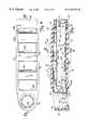
- FIG. 4is a top plan view of the housing of the armrest with the upper armrest pad removed;
- FIG. 5is a sectional view is taken as on line 5 — 5 in FIG. 4;
- FIG. 6is a sectional view taken on line 6 — 6 in FIG. 5;
- FIG. 7is a sectional view taken on line 7 — 7 in FIG. 5;
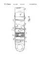
- FIG. 8is a bottom plan view of the armrest of FIG. 4 with the bottom pad removed.
- FIG. 9is a bottom perspective view of the molded housing for the armrest.
- stadium seating indicated generally at 10is used in modern theaters, includes that a first seat 12 and a second seat 14 that are mounted adjacent to each other. Additional seats would be mounted in a row.
- the seats 12 and 14each include a backrest 12 A and 14 A, respectively, and an upwardly folding or pivoting armrest 16 is mounted between the seats.
- the seatsinclude fixed frames or standards 18 that are mounted on the floor and extend upwardly to support the seat frame and are offset laterally to extend along the seat backs.
- the seat standardsinclude an upper end portion 20 and a bracket 21 that is spaced from and parallel to the upper end portion 20 .
- the armrest 16is positioned between the upper end portion 20 and the bracket 21 and is pivotally mounted thereto. Suitable holes including a pivot pin hole 22 , and a guide slot 26 are provided in the standard and offset bracket (FIG. 1 ).
- a pivot pin 24forms the pivotal mounting (FIG. 2 ).
- Slot 26 in the standard and bracketretains a guide pin 27 that passes through the slot and is mounted on the arm.
- the guide pin 27is attached to the arm 16 and is received in a slot 26 on both sides of the arm.
- the slot 26is in both bracket 21 and the upper end 20 of standard 18 so the pin 27 forms a stop at the ends of the slots, as well as guiding pivoting movement of the arm 16 .
- the pivoting armrest 16is shown in exploded view in FIG. 3, and includes a molded outer housing or shell 28 , that has side walls 34 and 36 , which are joined together with a top cross wall 38 and a bottom cross wall 40 at the pivoting end of the arm 16 .
- the side walls 34 and 36are also held together with three lower cross members 32 A, 32 B and 32 C on the lower side.
- the side walls 34 and 36are spaced apart, and leave openings at the top and bottom.
- the cross members 30 A- 30 Care recessed slightly below the upper edges of the side walls for mounting a pad.
- the lower cross membersare also recessed upwardly slightly in from the lower edges of the side walls for receiving the lower pad.
- the rear cross walls 38 and 40form a box section at the pivoting end of the arm.
- a cupholder 44is molded in place and extends forwardly from the front wall.
- the cupholder 44is an annular wall that, as shown, has suitable shoulder members 46 , positioned around the central axis of the wall.
- the shoulder members 46support a cup on an interior cupholder receptacle 48 .
- Receptacle 48has an open top and a drink cup can be inserted and supported on the bottom of the receptacle. Instead of shoulder members, the bottom of the receptacle can have cross straps or other wall portions for supporting a drink cup.
- the housing 28is mounted on a pivot support channel 52 that extends from the pivot end of the arm almost to the wall 42 .
- the pivot support channelas shown in FIG. 5 and 6, has side walls 54 and a top wall 56 joining the side walls.
- the lower side of the support channel 52is open.
- the side walls 54taper upwardly from the rear to the front.
- the front end the side walls 54are folded inwardly to form inwardly extending tongues 58 (see FIG. 7 ), extending from each of the side walls 54 and formed to slip over and bear on the top of a wall 33 A of channel shaped lower cross member 32 C.
- the walls 54are also notched as at 57 to receive the upper edge of the wall 33 B of channel shaped cross member 32 C.
- the lower edges of walls 54 of channel 52are above cross member 32 B and can rest on cross member 32 .
- the top surface of top wall 56 of channel 52bears against the depending walls of cross members 30 A, 30 B and 30 C.
- the channel 52can be forced into place until the notch 57 snaps over wall 33 B because of the resiliency of the housing, and then the channel 52 is held in place to support the housing.
- the rear portions of the side walls 54are provided with openings in which the pivot pin 24 and guide pin 22 are supported.
- the guide pinextends out from the side walls and is guided in the slots 26 on the upper end portion 20 and bracket 21 .
- the side walls 34 and 36 of housing 28have elongated slots 70 and 70 A to provide for clearance of the pins, when the parts are mounted onto the standards of the seat.
- the assemblyis then ready to receive pads at the top and bottom of the armrest.
- the pads for the top and bottomare identically formed, and while the housing 28 has different longitudinal curvatures at the top and the bottom, the pads are made to be sufficiently resilient so that they can accommodate these differences
- the pad 72 at the top and the pad 74 at the bottom of the armare identically constructed, and a flat flexible plate 76 is used as a support, and then the plates are suitably covered with foam.
- a foam layer 80is provided along the length of the plate 76 and then covered with a suitable fabric covering 82 .
- the fabric coveringas can be seen in FIG. 3, is stapled in place with staples 84 in a normal manner, to completely cover the foam and provide a soft pad for the armrest.
- the plate 76has tongues 86 and 88 at opposite ends thereof, which protrude out beyond the end of the foam and fabric slightly. The tongues are used for holding the pads in place in the outer housing.
- the plate 76has a first pair of lock pins 88 formed thereon and depending from the plate. These pins 88 are spaced laterally apart, as shown, and are spaced longitudinally from a second pair of pins 90 that also are integral with the plate 76 .
- the cross member 30 B in FIG. 3has a pair of openings 92 that are formed though hubs 92 A (see FIGS. 3 and 5 ), that are spaced apart and are aligned to receive the pins 88 of the top pads 72 , as shown in FIG. 3 .
- the pins 88serve to position the top pad and provide a frictional force to hold the pins retained in the hubs.
- the pins 90are positioned so that when the pad is used as a top pad 72 , the pins 90 will be positioned between the cross members 30 B and 30 C, and will not interfere with pad installation or use.
- the bottom cross member 32 Bhas openings 94 therein that are formed in upwardly extending hubs.
- the openings 94are of size to receive and hold the pins 90 , when the pad is being used as a bottom pad 74 .
- the pins 88will clear the cross members 32 A- 32 C and merely rest in between the cross members 30 A and 30 B when the pad is used as a bottom pad.
- FIG. 8which is a bottom view, the openings 92 can be seen.
- a reinforcing grid shown at 100can be utilized between the side walls 34 and 36 , and fill the channel shaped member 30 C for extra reinforcement in an area where heaviest loads are to be encountered.
- rear cross walls 38 and 40have edges that extend across the armrest between the side walls 34 and 36 , and these edges are shown in FIG. 6 at 38 A, and the edge for the lower wall 40 aligns therewith and is shown at 40 A in FIG. 5 .
- the forward wall 42extends vertically between the upper side of the armrest and the lower side, and has edge lips 42 A and 42 B that are formed straight across the space between the side walls 34 and 36 .
- the edge 38 A and lip 42 A at the top of the armrest, and the edges 40 A and lip 42 B at the lower edgesare spaced so that the pad plate 76 , which is flexible, can be bent up into a curve, generally as shown in dotted lines in FIG. 5 and the tongue ends 86 and 88 inserted under the edges of the front lip 42 A and the edges of rear walls 38 so that the top pad will be snapped in place and will come to rest down against the upper surfaces of the cross members 30 A- 30 C with the pins 88 in the respective holes.
- the tongues on the lower padwill be slipped under lip 42 B and edge 40 A by bending the plate 76 in a curve.
- the pins 90 and 88friction fit into the holes and are forced into place to hold the pads on the plastic housing, which of course is also supported on the metal channel 52 .
- the rear end of the housingcan have an end cap installed to finish off the appearance of the arm.
- the pivoting armrest 16has a cupholder receptacle 48 at its forward end, and a pivot structure at its rear end, and is supported adequately on a metal channel with the plastic housing being made to provide a molded decorative finish, and to receive pads at both the top and the bottom of the armrest.
- the curvature of the armrest top pad 72is greater than the line of the outer surface of the lower pad 74 , but the flexible plate 76 , which is made out of a suitable plastic, will conform to these two different shapes and will be held in place securely.
Landscapes
- Engineering & Computer Science (AREA)
- Transportation (AREA)
- Mechanical Engineering (AREA)
- Aviation & Aerospace Engineering (AREA)
- Physics & Mathematics (AREA)
- Thermal Sciences (AREA)
- Health & Medical Sciences (AREA)
- Dentistry (AREA)
- General Health & Medical Sciences (AREA)
- Passenger Equipment (AREA)
Abstract
Description
Claims (16)
Priority Applications (1)
| Application Number | Priority Date | Filing Date | Title |
|---|---|---|---|
| US09/348,777US6283551B1 (en) | 1999-07-07 | 1999-07-07 | Pivoting armrest with cupholder |
Applications Claiming Priority (1)
| Application Number | Priority Date | Filing Date | Title |
|---|---|---|---|
| US09/348,777US6283551B1 (en) | 1999-07-07 | 1999-07-07 | Pivoting armrest with cupholder |
Publications (1)
| Publication Number | Publication Date |
|---|---|
| US6283551B1true US6283551B1 (en) | 2001-09-04 |
Family
ID=23369492
Family Applications (1)
| Application Number | Title | Priority Date | Filing Date |
|---|---|---|---|
| US09/348,777Expired - Fee RelatedUS6283551B1 (en) | 1999-07-07 | 1999-07-07 | Pivoting armrest with cupholder |
Country Status (1)
| Country | Link |
|---|---|
| US (1) | US6283551B1 (en) |
Cited By (44)
| Publication number | Priority date | Publication date | Assignee | Title |
|---|---|---|---|---|
| US20020008415A1 (en)* | 2000-07-13 | 2002-01-24 | Jochen Bollaender | Holding device for a beverage container |
| USD461321S1 (en) | 2001-05-31 | 2002-08-13 | Figueras International Seating, S.A. | Seats |
| US6502899B2 (en)* | 2001-03-22 | 2003-01-07 | Shin Yeh Enterprise Co., Ltd. | Chair having an armrest with a detachable face panel |
| US6508508B1 (en)* | 2001-02-02 | 2003-01-21 | Daimlerchrysler Corporation | Armrest storage |
| US6607243B2 (en)* | 2001-03-23 | 2003-08-19 | Cosco Management, Inc. | Seat shell for juvenile vehicle seat |
| US20030154660A1 (en)* | 2001-10-19 | 2003-08-21 | Michael Berkowicz | Connector for arranging modular seats in a non-linear array |
| US6682143B2 (en)* | 2002-02-21 | 2004-01-27 | Evenflo Company, Inc. | Booster seat |
| US6776455B2 (en)* | 2002-08-02 | 2004-08-17 | B E Aerospace | Passenger seat and armrest pivot cover for passenger seat |
| WO2004095985A1 (en)* | 2003-04-29 | 2004-11-11 | Euro Seating International, S.A. | Method of producing armchair side panels and side panels thus produced |
| US20050081759A1 (en)* | 2002-02-19 | 2005-04-21 | Snead Rosemary A. | Worktable |
| US20050275271A1 (en)* | 2001-01-03 | 2005-12-15 | Richard Magnuson | Bracket for mounting either a fixed or a pivoting armrest |
| US20060066118A1 (en)* | 2004-09-28 | 2006-03-30 | Bogdan Radu | Assembly for supporting an article in a vehicle |
| US20060071497A1 (en)* | 2004-10-01 | 2006-04-06 | Bogdan Radu | Console and object holder assembly for a vehicle |
| US20060108816A1 (en)* | 2004-11-22 | 2006-05-25 | Bogdan Radu | Vehicle console with armrest extension |
| USRE39392E1 (en) | 2001-06-05 | 2006-11-14 | Caddy Products, Inc. | Locking bracket and cupholder for seat frame |
| US20070267910A1 (en)* | 2006-05-16 | 2007-11-22 | Caddy Products, Inc. | Armrest cupholder |
| US20070278839A1 (en)* | 2006-06-06 | 2007-12-06 | Edwards John R | Chair arm cup holder |
| FR2902627A1 (en)* | 2006-06-23 | 2007-12-28 | Quinette Gallay Sa | Arm-rest for theatre and conference room, has thermoplastic body, whose recess encloses elastomer lining that projects with respect to edge of recess to constitute part of contact surface between arm-rest and forearm of user of arm-chair |
| USD576431S1 (en)* | 2007-05-03 | 2008-09-09 | Julius Blum Gmbh | Fitting for furniture |
| US20090064549A1 (en)* | 2007-09-12 | 2009-03-12 | Bruce Shad E | Advertising apparatus and method |
| USD626756S1 (en) | 2008-05-27 | 2010-11-09 | Herman Miller, Inc. | Chair |
| US20110121619A1 (en)* | 2008-07-28 | 2011-05-26 | The Coleman Company, Inc. | Stemmed glass holder |
| EP2059149A4 (en)* | 2006-07-04 | 2012-09-12 | Brent Cymbalski | Human form child car safety seat |
| CN102783833A (en)* | 2012-08-05 | 2012-11-21 | 陈召龙 | Chair for providing convenience for examination |
| USD677953S1 (en)* | 2010-02-04 | 2013-03-19 | For Life Products, Inc. | Portable armrest |
| EP2569183A4 (en)* | 2010-05-10 | 2015-03-18 | Be Aerospace Inc | ARMREST ASSEMBLY FOR AIRCRAFT PASSENGER SEAT |
| CN105902017A (en)* | 2016-06-23 | 2016-08-31 | 安庆市亿网科技有限公司 | Bench with handrails |
| CN106108454A (en)* | 2016-06-23 | 2016-11-16 | 安庆市亿网科技有限公司 | A kind of public bench of Armrest |
| CN106108468A (en)* | 2016-06-23 | 2016-11-16 | 安庆市亿网科技有限公司 | A kind of bench |
| CN104287493B (en)* | 2014-10-20 | 2017-01-25 | 安吉县盛信办公家具有限公司 | Novel row chair |
| USD786597S1 (en)* | 2016-06-29 | 2017-05-16 | Thomas Gao | Armrest |
| GB2545451A (en)* | 2015-12-16 | 2017-06-21 | Cine Italia Design Ltd | Audience seat |
| US9824611B2 (en) | 2007-09-12 | 2017-11-21 | Branded Seats, Llc. | Advertising apparatus and method |
| CN107472540A (en)* | 2017-08-21 | 2017-12-15 | 中国民用航空总局第二研究所 | A kind of new aero seat handrail |
| US10093215B2 (en)* | 2015-07-14 | 2018-10-09 | Lear Corporation | Vehicle armrest structure with organic fibers |
| US10207613B2 (en)* | 2016-12-01 | 2019-02-19 | Toyota Boshoku Kabushiki Kaisha | Armrest for vehicle seat |
| US20190232839A1 (en)* | 2018-02-01 | 2019-08-01 | Ford Global Technologies, Llc | Vehicle seating arrangement with deployable bolsters |
| US10850849B2 (en) | 2018-01-08 | 2020-12-01 | B/E Aerospace, Inc. | Vehicle armrest with cup holder |
| US11229291B1 (en) | 2021-05-04 | 2022-01-25 | Michael David Collier | Ergonomic motion chair |
| US11241099B2 (en) | 2019-03-18 | 2022-02-08 | Irwin Seating Company | Cup holder for attachment at back of auditorium/theater seating |
| US11382444B2 (en) | 2019-04-08 | 2022-07-12 | Branded Seats USA, LLC | Adjustable mounting bracket apparatus and method |
| US11507937B2 (en) | 2019-04-08 | 2022-11-22 | Branded Seats USA, LLC | Informative apparatus and method |
| US11825949B2 (en) | 2021-05-04 | 2023-11-28 | Michael David Collier | Ergonomic motion chair |
| USD1053646S1 (en) | 2022-05-23 | 2024-12-10 | Michael David Collier | Chair with seatback |
Citations (24)
| Publication number | Priority date | Publication date | Assignee | Title |
|---|---|---|---|---|
| US2704114A (en) | 1953-05-18 | 1955-03-15 | Radie S Jackson | Portable arm rest |
| US4141586A (en)* | 1976-10-28 | 1979-02-27 | Recaro Gmbh & Co. | Vehicle seat |
| US4270798A (en)* | 1979-07-10 | 1981-06-02 | Coach & Car Equipment Corporation | Breakaway arm for seat |
| US4331360A (en) | 1980-10-27 | 1982-05-25 | Magee Plastics Company | Resilient accessory for seat or the like |
| DE3143957A1 (en) | 1981-11-05 | 1983-05-11 | Adam Opel AG, 6090 Rüsselsheim | Central armrest for the front seats of a motor vehicle |
| US4435011A (en)* | 1981-03-26 | 1984-03-06 | Nissan Motor Company, Limited | Seat with a dual-adjustable armrest |
| US4613048A (en) | 1985-05-13 | 1986-09-23 | Mcgill Dennis E | Automotive console beverage container support |
| US4795211A (en) | 1987-12-11 | 1989-01-03 | Cine Coasters, Inc. | Universal container holder |
| US4863134A (en) | 1987-11-30 | 1989-09-05 | American Multi-Cinema, Inc. | Combination cup holder and armrest |
| USD326589S (en) | 1989-04-25 | 1992-06-02 | Paone/Barron Joint Venture | Portable glass holder or similar article |
| US5232262A (en) | 1992-04-01 | 1993-08-03 | Shin Yeh Enterprise Co., Ltd. | Arm of an armchair with means to support a bottle or a cup |
| US5234251A (en) | 1992-05-13 | 1993-08-10 | Mts Northwest Sound, Inc. | Seat arm attachment |
| US5238212A (en) | 1992-09-24 | 1993-08-24 | Dechellis Don M | Beverage container support |
| US5302000A (en) | 1992-10-21 | 1994-04-12 | Mts Northwest Sound, Inc. | Cup holder armrest |
| US5320406A (en)* | 1993-06-24 | 1994-06-14 | North Kevin A | Combination cup holder and arm rest |
| US5342115A (en)* | 1992-05-21 | 1994-08-30 | Gestind-M.B. "Manifattura Di Bruzolo" S.P.A. | Arm rest for motor vehicle seats |
| USD350259S (en) | 1992-10-14 | 1994-09-06 | Mts Northwest Sound, Inc. | Rear cup holder armrest |
| US5409297A (en)* | 1993-01-21 | 1995-04-25 | Gestind-M.B. "Manifattura Di Bruzolo" S.P.A. | Arm rest for motor vehicle rear seats |
| US5660433A (en)* | 1995-03-27 | 1997-08-26 | Mercedes-Benz Ag | Arm rest for a passenger vehicle |
| US5678896A (en)* | 1996-08-26 | 1997-10-21 | Chung; Peter | Armrest adjusting device |
| US5769495A (en)* | 1992-11-20 | 1998-06-23 | Jukova Oy | Adjusting mechanism for a support element included in a seat and pivotable in the vertical plane |
| US5997081A (en)* | 1997-01-08 | 1999-12-07 | Honda Giken Kogyo Kabushiki Kaisha | Seat for a vehicle |
| US6047444A (en)* | 1998-09-14 | 2000-04-11 | Fisher Dynamics Corporation | Positive lock armrest mechanism |
| US6050645A (en)* | 1998-03-04 | 2000-04-18 | Tachi-S Engineering U.S.A., Inc. | Clutching mechanism for an infinitely adjustable armrest |
- 1999
- 1999-07-07USUS09/348,777patent/US6283551B1/ennot_activeExpired - Fee Related
Patent Citations (24)
| Publication number | Priority date | Publication date | Assignee | Title |
|---|---|---|---|---|
| US2704114A (en) | 1953-05-18 | 1955-03-15 | Radie S Jackson | Portable arm rest |
| US4141586A (en)* | 1976-10-28 | 1979-02-27 | Recaro Gmbh & Co. | Vehicle seat |
| US4270798A (en)* | 1979-07-10 | 1981-06-02 | Coach & Car Equipment Corporation | Breakaway arm for seat |
| US4331360A (en) | 1980-10-27 | 1982-05-25 | Magee Plastics Company | Resilient accessory for seat or the like |
| US4435011A (en)* | 1981-03-26 | 1984-03-06 | Nissan Motor Company, Limited | Seat with a dual-adjustable armrest |
| DE3143957A1 (en) | 1981-11-05 | 1983-05-11 | Adam Opel AG, 6090 Rüsselsheim | Central armrest for the front seats of a motor vehicle |
| US4613048A (en) | 1985-05-13 | 1986-09-23 | Mcgill Dennis E | Automotive console beverage container support |
| US4863134A (en) | 1987-11-30 | 1989-09-05 | American Multi-Cinema, Inc. | Combination cup holder and armrest |
| US4795211A (en) | 1987-12-11 | 1989-01-03 | Cine Coasters, Inc. | Universal container holder |
| USD326589S (en) | 1989-04-25 | 1992-06-02 | Paone/Barron Joint Venture | Portable glass holder or similar article |
| US5232262A (en) | 1992-04-01 | 1993-08-03 | Shin Yeh Enterprise Co., Ltd. | Arm of an armchair with means to support a bottle or a cup |
| US5234251A (en) | 1992-05-13 | 1993-08-10 | Mts Northwest Sound, Inc. | Seat arm attachment |
| US5342115A (en)* | 1992-05-21 | 1994-08-30 | Gestind-M.B. "Manifattura Di Bruzolo" S.P.A. | Arm rest for motor vehicle seats |
| US5238212A (en) | 1992-09-24 | 1993-08-24 | Dechellis Don M | Beverage container support |
| USD350259S (en) | 1992-10-14 | 1994-09-06 | Mts Northwest Sound, Inc. | Rear cup holder armrest |
| US5302000A (en) | 1992-10-21 | 1994-04-12 | Mts Northwest Sound, Inc. | Cup holder armrest |
| US5769495A (en)* | 1992-11-20 | 1998-06-23 | Jukova Oy | Adjusting mechanism for a support element included in a seat and pivotable in the vertical plane |
| US5409297A (en)* | 1993-01-21 | 1995-04-25 | Gestind-M.B. "Manifattura Di Bruzolo" S.P.A. | Arm rest for motor vehicle rear seats |
| US5320406A (en)* | 1993-06-24 | 1994-06-14 | North Kevin A | Combination cup holder and arm rest |
| US5660433A (en)* | 1995-03-27 | 1997-08-26 | Mercedes-Benz Ag | Arm rest for a passenger vehicle |
| US5678896A (en)* | 1996-08-26 | 1997-10-21 | Chung; Peter | Armrest adjusting device |
| US5997081A (en)* | 1997-01-08 | 1999-12-07 | Honda Giken Kogyo Kabushiki Kaisha | Seat for a vehicle |
| US6050645A (en)* | 1998-03-04 | 2000-04-18 | Tachi-S Engineering U.S.A., Inc. | Clutching mechanism for an infinitely adjustable armrest |
| US6047444A (en)* | 1998-09-14 | 2000-04-11 | Fisher Dynamics Corporation | Positive lock armrest mechanism |
Cited By (56)
| Publication number | Priority date | Publication date | Assignee | Title |
|---|---|---|---|---|
| US20020008415A1 (en)* | 2000-07-13 | 2002-01-24 | Jochen Bollaender | Holding device for a beverage container |
| US7131690B2 (en)* | 2000-07-29 | 2006-11-07 | Fischerwerke Artur Fischer Gmbh & Co. Kg | Holding device for a beverage container |
| US20050275271A1 (en)* | 2001-01-03 | 2005-12-15 | Richard Magnuson | Bracket for mounting either a fixed or a pivoting armrest |
| US6508508B1 (en)* | 2001-02-02 | 2003-01-21 | Daimlerchrysler Corporation | Armrest storage |
| US6502899B2 (en)* | 2001-03-22 | 2003-01-07 | Shin Yeh Enterprise Co., Ltd. | Chair having an armrest with a detachable face panel |
| US6607243B2 (en)* | 2001-03-23 | 2003-08-19 | Cosco Management, Inc. | Seat shell for juvenile vehicle seat |
| USD461321S1 (en) | 2001-05-31 | 2002-08-13 | Figueras International Seating, S.A. | Seats |
| USRE39392E1 (en) | 2001-06-05 | 2006-11-14 | Caddy Products, Inc. | Locking bracket and cupholder for seat frame |
| USRE41624E1 (en) | 2001-06-05 | 2010-09-07 | Caddy Products, Inc. | Locking bracket and cupholder for seat frame |
| US20030154660A1 (en)* | 2001-10-19 | 2003-08-21 | Michael Berkowicz | Connector for arranging modular seats in a non-linear array |
| US20050081759A1 (en)* | 2002-02-19 | 2005-04-21 | Snead Rosemary A. | Worktable |
| US20040155500A1 (en)* | 2002-02-21 | 2004-08-12 | David Amirault | Booster seat |
| US6682143B2 (en)* | 2002-02-21 | 2004-01-27 | Evenflo Company, Inc. | Booster seat |
| US6776455B2 (en)* | 2002-08-02 | 2004-08-17 | B E Aerospace | Passenger seat and armrest pivot cover for passenger seat |
| WO2004095985A1 (en)* | 2003-04-29 | 2004-11-11 | Euro Seating International, S.A. | Method of producing armchair side panels and side panels thus produced |
| ES2268919A1 (en)* | 2003-04-29 | 2007-03-16 | Euro Seating International, S.A. | Method of producing armchair side panels and side panels thus produced |
| ES2268919B1 (en)* | 2003-04-29 | 2008-03-01 | Euro Seating International, S.A. | IMPROVEMENTS INTRODUCED IN THE PATENT OF INVENTION 200300973 BY "PROCEDURE FOR OBTAINING COVERS OF ARMCHAIRS, AND COSTS AS OBTAINED. |
| US20060066118A1 (en)* | 2004-09-28 | 2006-03-30 | Bogdan Radu | Assembly for supporting an article in a vehicle |
| US7264291B2 (en) | 2004-09-28 | 2007-09-04 | Lear Corporation | Assembly for supporting an article in a vehicle |
| US20060071497A1 (en)* | 2004-10-01 | 2006-04-06 | Bogdan Radu | Console and object holder assembly for a vehicle |
| US7147259B2 (en) | 2004-10-01 | 2006-12-12 | Lear Corporation | Console and object holder assembly for a vehicle |
| US20060108816A1 (en)* | 2004-11-22 | 2006-05-25 | Bogdan Radu | Vehicle console with armrest extension |
| US7192070B2 (en) | 2004-11-22 | 2007-03-20 | Lear Corporation | Vehicle console with armrest extension |
| US20070267910A1 (en)* | 2006-05-16 | 2007-11-22 | Caddy Products, Inc. | Armrest cupholder |
| US7614703B2 (en)* | 2006-05-16 | 2009-11-10 | Caddy Products, Inc. | Armrest cupholder |
| US20070278839A1 (en)* | 2006-06-06 | 2007-12-06 | Edwards John R | Chair arm cup holder |
| FR2902627A1 (en)* | 2006-06-23 | 2007-12-28 | Quinette Gallay Sa | Arm-rest for theatre and conference room, has thermoplastic body, whose recess encloses elastomer lining that projects with respect to edge of recess to constitute part of contact surface between arm-rest and forearm of user of arm-chair |
| EP2059149A4 (en)* | 2006-07-04 | 2012-09-12 | Brent Cymbalski | Human form child car safety seat |
| USD576431S1 (en)* | 2007-05-03 | 2008-09-09 | Julius Blum Gmbh | Fitting for furniture |
| US7681346B2 (en) | 2007-09-12 | 2010-03-23 | Bruce Shad E | Advertising apparatus and method |
| US9032651B2 (en) | 2007-09-12 | 2015-05-19 | Branded Seats, Llc. | Advertising apparatus and method |
| US20090064549A1 (en)* | 2007-09-12 | 2009-03-12 | Bruce Shad E | Advertising apparatus and method |
| US9824611B2 (en) | 2007-09-12 | 2017-11-21 | Branded Seats, Llc. | Advertising apparatus and method |
| US20100162598A1 (en)* | 2007-09-12 | 2010-07-01 | Bruce Shad E | Advertising apparatus and method |
| USD626756S1 (en) | 2008-05-27 | 2010-11-09 | Herman Miller, Inc. | Chair |
| US20110121619A1 (en)* | 2008-07-28 | 2011-05-26 | The Coleman Company, Inc. | Stemmed glass holder |
| USD677953S1 (en)* | 2010-02-04 | 2013-03-19 | For Life Products, Inc. | Portable armrest |
| EP2569183A4 (en)* | 2010-05-10 | 2015-03-18 | Be Aerospace Inc | ARMREST ASSEMBLY FOR AIRCRAFT PASSENGER SEAT |
| CN102783833A (en)* | 2012-08-05 | 2012-11-21 | 陈召龙 | Chair for providing convenience for examination |
| CN104287493B (en)* | 2014-10-20 | 2017-01-25 | 安吉县盛信办公家具有限公司 | Novel row chair |
| US10093215B2 (en)* | 2015-07-14 | 2018-10-09 | Lear Corporation | Vehicle armrest structure with organic fibers |
| GB2545451A (en)* | 2015-12-16 | 2017-06-21 | Cine Italia Design Ltd | Audience seat |
| CN105902017A (en)* | 2016-06-23 | 2016-08-31 | 安庆市亿网科技有限公司 | Bench with handrails |
| CN106108454A (en)* | 2016-06-23 | 2016-11-16 | 安庆市亿网科技有限公司 | A kind of public bench of Armrest |
| CN106108468A (en)* | 2016-06-23 | 2016-11-16 | 安庆市亿网科技有限公司 | A kind of bench |
| USD786597S1 (en)* | 2016-06-29 | 2017-05-16 | Thomas Gao | Armrest |
| US10207613B2 (en)* | 2016-12-01 | 2019-02-19 | Toyota Boshoku Kabushiki Kaisha | Armrest for vehicle seat |
| CN107472540A (en)* | 2017-08-21 | 2017-12-15 | 中国民用航空总局第二研究所 | A kind of new aero seat handrail |
| US10850849B2 (en) | 2018-01-08 | 2020-12-01 | B/E Aerospace, Inc. | Vehicle armrest with cup holder |
| US20190232839A1 (en)* | 2018-02-01 | 2019-08-01 | Ford Global Technologies, Llc | Vehicle seating arrangement with deployable bolsters |
| US11241099B2 (en) | 2019-03-18 | 2022-02-08 | Irwin Seating Company | Cup holder for attachment at back of auditorium/theater seating |
| US11382444B2 (en) | 2019-04-08 | 2022-07-12 | Branded Seats USA, LLC | Adjustable mounting bracket apparatus and method |
| US11507937B2 (en) | 2019-04-08 | 2022-11-22 | Branded Seats USA, LLC | Informative apparatus and method |
| US11229291B1 (en) | 2021-05-04 | 2022-01-25 | Michael David Collier | Ergonomic motion chair |
| US11825949B2 (en) | 2021-05-04 | 2023-11-28 | Michael David Collier | Ergonomic motion chair |
| USD1053646S1 (en) | 2022-05-23 | 2024-12-10 | Michael David Collier | Chair with seatback |
Similar Documents
| Publication | Publication Date | Title |
|---|---|---|
| US6283551B1 (en) | Pivoting armrest with cupholder | |
| US6386629B1 (en) | Vehicle seat | |
| US5582460A (en) | Pivotable and height-adjustable chair back rest assembly and blow-molded back rest therefor | |
| US12077079B2 (en) | Seat device | |
| JP7509075B2 (en) | Seat device | |
| JPH06125826A (en) | Seat back rest in vehicle | |
| US20090115235A1 (en) | Piece of Seating Furniture, in Particular Office Chair | |
| US20030102703A1 (en) | Theater seat assembly | |
| US6811227B2 (en) | Firm cushion | |
| US5246269A (en) | Armrest | |
| US6959964B1 (en) | Portable backrest structure | |
| JP2000093250A (en) | Body support device such as chair | |
| JPWO2008004583A1 (en) | Reclining seat structure | |
| CN109263523B (en) | Seat frame structure and seat comprising same | |
| US3095239A (en) | Chair | |
| KR20140004925A (en) | A chair having a variable back rest | |
| US3652127A (en) | Counterbalanced folding seats with position lock | |
| US3205009A (en) | Automotive seat cushions | |
| KR200371544Y1 (en) | The chair having a head-rest and a hanger | |
| KR20210068704A (en) | Seat for vehicle | |
| KR200147148Y1 (en) | Armrest for a car | |
| JPH0523098Y2 (en) | ||
| JP4199965B2 (en) | Chair backrest device | |
| JP7291529B2 (en) | Furniture and connecting chairs | |
| JP7575905B2 (en) | chair |
Legal Events
| Date | Code | Title | Description |
|---|---|---|---|
| AS | Assignment | Owner name:MEDIA TECHNOLOGY SOURCE, INC., MINNESOTA Free format text:ASSIGNMENT OF ASSIGNORS INTEREST;ASSIGNOR:BERGIN, PETER W.A.;REEL/FRAME:010168/0394 Effective date:19990701 | |
| CC | Certificate of correction | ||
| AS | Assignment | Owner name:MEDIA TECHNOLOGY SOURCE OF MINNESOTA, LLC, CALIFOR Free format text:CHANGE OF NAME;ASSIGNOR:MEDIA TECHNOLOGY SOURCE, LLC;REEL/FRAME:014102/0971 Effective date:20020506 Owner name:MEDIA TECHNOLOGY SOURCE, LLC, CALIFORNIA Free format text:MERGER;ASSIGNOR:MEDIA TECHNOLOGY SOURCE, INC.;REEL/FRAME:014102/0729 Effective date:20000601 | |
| AS | Assignment | Owner name:CP ACQUISITION COMPANY, LLC, MINNESOTA Free format text:ASSIGNMENT OF ASSIGNORS INTEREST;ASSIGNOR:MEDIA TECHNOLOGY SOURCE OF MINNESOTA, INC.;REEL/FRAME:014373/0509 Effective date:20030729 | |
| AS | Assignment | Owner name:CADDY PRODUCTS, INC., MINNESOTA Free format text:ASSIGNMENT OF ASSIGNORS INTEREST;ASSIGNOR:CP ACQUISITION COMPANY, LLC;REEL/FRAME:014462/0240 Effective date:20030903 | |
| AS | Assignment | Owner name:CP ACQUISITION COMPANY, LLC, MINNESOTA Free format text:CORRECTIVE ASSIGNMENT TO CORRECT THE NAME OF THE ASSIGNOR, PREVIOUSLY RECORDED ON REEL 014373 FRAME 0589;ASSIGNOR:MEDIA TECHNOLOGY SOURCE OF MINNESOTA, LLC;REEL/FRAME:015116/0205 Effective date:20030729 | |
| FPAY | Fee payment | Year of fee payment:4 | |
| FPAY | Fee payment | Year of fee payment:8 | |
| REMI | Maintenance fee reminder mailed | ||
| LAPS | Lapse for failure to pay maintenance fees | ||
| STCH | Information on status: patent discontinuation | Free format text:PATENT EXPIRED DUE TO NONPAYMENT OF MAINTENANCE FEES UNDER 37 CFR 1.362 | |
| FP | Expired due to failure to pay maintenance fee | Effective date:20130904 |