US6283206B1 - Gas lift umbilical cable and termination assemblies therefor - Google Patents
Gas lift umbilical cable and termination assemblies thereforDownload PDFInfo
- Publication number
- US6283206B1 US6283206B1US09/347,586US34758699AUS6283206B1US 6283206 B1US6283206 B1US 6283206B1US 34758699 AUS34758699 AUS 34758699AUS 6283206 B1US6283206 B1US 6283206B1
- Authority
- US
- United States
- Prior art keywords
- umbilical
- flexible pipe
- layer
- attached
- sealing
- Prior art date
- Legal status (The legal status is an assumption and is not a legal conclusion. Google has not performed a legal analysis and makes no representation as to the accuracy of the status listed.)
- Expired - Fee Related
Links
- 230000000712assemblyEffects0.000titleclaimsdescription8
- 238000000429assemblyMethods0.000titleclaimsdescription8
- 238000007789sealingMethods0.000claimsabstractdescription52
- 239000000945fillerSubstances0.000claimsdescription26
- 239000000463materialSubstances0.000claimsdescription17
- 230000002706hydrostatic effectEffects0.000claimsdescription14
- 230000001681protective effectEffects0.000claimsdescription5
- 230000004888barrier functionEffects0.000description12
- 238000005299abrasionMethods0.000description11
- 238000004519manufacturing processMethods0.000description11
- OKKJLVBELUTLKV-UHFFFAOYSA-NMethanolChemical compoundOCOKKJLVBELUTLKV-UHFFFAOYSA-N0.000description9
- 239000012530fluidSubstances0.000description8
- 239000013535sea waterSubstances0.000description6
- 229910000831SteelInorganic materials0.000description5
- 239000004519greaseSubstances0.000description5
- 229920001778nylonPolymers0.000description5
- 229920000728polyesterPolymers0.000description5
- 239000010959steelSubstances0.000description5
- 239000004677NylonSubstances0.000description4
- 238000013022ventingMethods0.000description4
- GSDQYSSLIKJJOG-UHFFFAOYSA-N4-chloro-2-(3-chloroanilino)benzoic acidChemical compoundOC(=O)C1=CC=C(Cl)C=C1NC1=CC=CC(Cl)=C1GSDQYSSLIKJJOG-UHFFFAOYSA-N0.000description3
- 230000008901benefitEffects0.000description3
- 238000000034methodMethods0.000description3
- 238000004382pottingMethods0.000description3
- XLYOFNOQVPJJNP-UHFFFAOYSA-NwaterSubstancesOXLYOFNOQVPJJNP-UHFFFAOYSA-N0.000description3
- CSCPPACGZOOCGX-UHFFFAOYSA-NAcetoneChemical compoundCC(C)=OCSCPPACGZOOCGX-UHFFFAOYSA-N0.000description2
- 229920000571Nylon 11Polymers0.000description2
- 239000004760aramidSubstances0.000description2
- 229920003235aromatic polyamidePolymers0.000description2
- 238000010276constructionMethods0.000description2
- 238000001125extrusionMethods0.000description2
- 239000002184metalSubstances0.000description2
- 238000012544monitoring processMethods0.000description2
- CDBRNDSHEYLDJV-FVGYRXGTSA-Mnaproxen sodiumChemical compound[Na+].C1=C([C@H](C)C([O-])=O)C=CC2=CC(OC)=CC=C21CDBRNDSHEYLDJV-FVGYRXGTSA-M0.000description2
- 238000010943off-gassingMethods0.000description2
- 229920001296polysiloxanePolymers0.000description2
- 239000001993waxSubstances0.000description2
- 229910000975Carbon steelInorganic materials0.000description1
- 239000004743PolypropyleneSubstances0.000description1
- 239000004959RilsanSubstances0.000description1
- 239000000853adhesiveSubstances0.000description1
- 230000001070adhesive effectEffects0.000description1
- 238000005452bendingMethods0.000description1
- 230000009172burstingEffects0.000description1
- 239000010962carbon steelSubstances0.000description1
- 230000008859changeEffects0.000description1
- 238000005260corrosionMethods0.000description1
- 230000007797corrosionEffects0.000description1
- 230000008878couplingEffects0.000description1
- 238000010168coupling processMethods0.000description1
- 238000005859coupling reactionMethods0.000description1
- 238000013461designMethods0.000description1
- 238000001035dryingMethods0.000description1
- 239000004744fabricSubstances0.000description1
- 238000011068loading methodMethods0.000description1
- 238000005259measurementMethods0.000description1
- 230000004048modificationEffects0.000description1
- 238000012986modificationMethods0.000description1
- 238000012806monitoring deviceMethods0.000description1
- 238000009931pascalizationMethods0.000description1
- 229920000642polymerPolymers0.000description1
- -1polypropylenePolymers0.000description1
- 229920001155polypropylenePolymers0.000description1
- 229920002635polyurethanePolymers0.000description1
- 239000004814polyurethaneSubstances0.000description1
- 239000007787solidSubstances0.000description1
- 238000006467substitution reactionMethods0.000description1
- 239000011800void materialSubstances0.000description1
- 238000004804windingMethods0.000description1
Images


Classifications
- E—FIXED CONSTRUCTIONS
- E21—EARTH OR ROCK DRILLING; MINING
- E21B—EARTH OR ROCK DRILLING; OBTAINING OIL, GAS, WATER, SOLUBLE OR MELTABLE MATERIALS OR A SLURRY OF MINERALS FROM WELLS
- E21B17/00—Drilling rods or pipes; Flexible drill strings; Kellies; Drill collars; Sucker rods; Cables; Casings; Tubings
- E21B17/20—Flexible or articulated drilling pipes, e.g. flexible or articulated rods, pipes or cables
- E21B17/203—Flexible or articulated drilling pipes, e.g. flexible or articulated rods, pipes or cables with plural fluid passages
Definitions
- the disclosures hereinrelate generally to collapse resistant umbilical structures and more particularly to gas lift umbilical and end termination assemblies.
- Oil from oil bearing reservoirsis sometimes produced by the inherent reservoir pressure. In many cases, however, the reservoir lacks sufficient inherent pressure to force the oil from the reservoir upwardly to a wellhead structure where the oil is transported from the wellhead structure by flowlines.
- a number of methodsmay be used to artificially produce pressure to force the oil products to the wellhead.
- gas liftOne common method is known as gas lift whereby gas is injected through a gas lift hose under controlled pressure into the annulus between the production tubing and the well casing.
- the gasmixes with and aerates the fluids in the production tubing thereby providing a lifting force for lifting the fluids to the surface.
- the gas that is injectedis commonly referred to as an export gas.
- Methanolmay also be injected to reduce the amount of wax accumulated in the production lines.
- umbilicals, hoses, risers and the likeIn deep water subsea oil field operations, umbilicals, hoses, risers and the like generally must be resistant to collapse due to hydrostatic pressure.
- the collapse pressureis the external hydrostatic pressure required to cause the umbilical structure to buckle.
- the hydrostatic pressureis proportional to the depth of the seawater such that the hydrostatic pressure increases with increasing seawater depths. For example, at a water depth of 340 meters, the hydrostatic pressure is approximately 500 psi.
- Gas lift hosesare commonly used in subsea oil production operations.
- a typical gas lift hoseincludes a core, an inner sheath, a kevlar-aramid armor layer and an outer sheath.
- commercially/available gas lift hosesgenerally do not have sufficient compressive hoop strength to resist hydrostatic collapse.
- These types of hosesare typically constantly pressurized to prevent the hose from collapsing. In the event that pressure is lost, the hose will collapse due to the hydrostatic pressure. It is common for the collapse to result in permanent damage to the hose.
- a common alternative design for gas lift hose elementsis to add a carcass internal to the hose. This carcass is typically some type of steel to resist the hydrostatic pressure. This requires different production processes and equipment than is normally used.
- One embodimentaccordingly, provides a umbilical having at least one collapsible hose carried within a non-collapsible flexible pipe.
- an umbilicalincluding a flexible pipe having a collapse resistant wall and a first sealing layer formed on an interior surface of the collapse resistant wall. The interior surface defines a longitudinal passage.
- a plurality of flexible conveyance elementsare mounted within the longitudinal passage extending from a first end of the flexible pipe to a second end thereof. At least a portion of the conveyance elements have a collapsible wall.
- a key advantage of an umbilical according to the present embodimentsis that the conveyance elements can be constructed of conveyance elements such standard hydraulic hoses having collapsible wall constructions. These types of standard hoses are less expensive than specialized hoses.
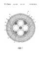
- FIG. 1is a cross sectional view illustrating an embodiment of a gas lift umbilical.
- FIG. 2is a fragmented cross-sectional view illustrating an embodiment of a gas lift umbilical.
- FIG. 3is a fragmentary cross-sectional view illustrating an embodiment of the protective sheath of the gas lift umbilical.
- FIG. 4is a fragmentary cross-sectional view illustrating an embodiment of the various layers in the flexible pipe of a gas lift umbilical.
- FIG. 5is a partial side view illustrating an embodiment of a topside termination assembly.
- FIG. 6is a partial side view illustrating an embodiment of a subsea termination assembly.
- FIG. 7is a fragmentary side view illustrating an embodiment of the flexible pipe terminating components of a topside termination assembly.
- FIG. 8is a fragmentary side view illustrating an embodiment of the clamping device for securing the wire rope fillers.
- FIGS. 1 and 2illustrate an embodiment of a gas lift umbilical 10 , hereinafter referred to as a GLU.
- the GLU 10includes a core 12 surrounded by a flexible pipe 14 .
- the flexible pipe 14isolates the core L 2 from hydrostatic pressure.
- the core 12includes a protective sheath 15 formed to encase the gas lift hoses 16 , stranded fillers 18 , wire rope fillers 20 , and air hoses 22 .
- Each gas lift hose 16is a standard hydraulic hose having a collapsible wall such as a FURON SYNFLEX 33GL-20000 11 ⁇ 4′′ gas lift hose.
- FURON SYNFLEX 33GL-20000is a gas lift hose rated to 3000 psi with a NYLON 11 inner sheath, an aramid braid armor layer, and a polyurethane outer sheath.
- a greaseis applied to the gas lift hoses 16 during manufacturing of the core 12 .
- the greaseprevents adhesion of the gas lift hoses 16 to adjacent components of the core 12 , allowing the gas lift hoses 16 to move freely relative to the adjacent components.
- the greaseis preferably a silicone grease such as DOW CORNING 4 silicone grease.
- Each wire rope filler 20consists of a sheath 24 extruded over a plurality of helically wound steel strands 26 .
- the sheathmay be formed of nylon or any other suitable material.
- One wire rope filler 20may have a sheath 24 of a different color than the others to provide a key to determine hose identification from each end.
- the key selection requirements for material used for the wire rope filler 20are weight, abrasion resistance, bending stiffness and fatigue resistance.
- the stranded fillers 18are added as a manufacturing aid.
- the stranded fillersfill the void between each gas lift hose 16 and the protective sheath 15 .
- the stranded filler 18may be manufactured by slitting a single ribbon of material such as a polypropylene. It is preferred that the stranded filler 18 be stranded rather than solid such that it can effectively conform to and shape around the gas lift hoses 16 and wire rope fillers 20 .
- the air hoses 22enable the moisture content at the subsea end of the umbilical to be monitored.
- the air hoses 22may be formed of nylon or other suitable material.
- the air hoses 22are small enough to fit into the voids between two gas lift hoses 16 and an adjacent wire rope filler 20 .
- the flexible pipe 14includes an armor layer 27 that is consists of a circumferentially wound strip of material such as steel or other suitable material.
- the armor layer 27is wound directly over the abrasion resistant layer of the core 12 .
- the armor layer 27resists internal and external pressure in the hoop direction. The strips of material forming the armor layer 27 interlock but do not preclude the GLU 10 from being flexed.
- the protective sheath 15includes an extruded core abrasion resistant layer 28 formed over a barrier layer 30 .
- the core abrasion resistant layer 28protects the underlying tape layers from abrasion.
- the core abrasion resistant layer 28also adds structural stiffness to the core 12 .
- the barrier layer 30includes three tape layers.
- the first barrier tape layer 32is formed over the contents of the core 12 to protect the contents from heat during extrusion of the core abrasion resistant layer 28 .
- the first barrier tape layermay be a corrugated tape of extruded polyester.
- a second barrier tape layer 34is formed over the first barrier tape layer 32 .
- the second barrier tape layermay be a high tensile filament tape consisting of a polyester backing reinforced with continuous polyester yarn filament and bonded to a pressure activated adhesive.
- a third barrier tape layer 36is applied over the second tape layer 34 to minimize outgassing from the second barrier tape layer 34 and to provide a smooth surface over which the abrasion resistant layer 28 can be extruded.
- the flexible pipe 14includes the armor layer 27 that consists of a circumferentially wound strip of material such as steel or other suitable material.
- the armor layer 27is wound directly over the abrasion resistant layer of the core 12 .
- the armor layer 27resists internal and external pressures by virtue of its strength in the hoop direction. Adjacent windings of the strips interlock but do not preclude the GLU 10 from being flexed.
- an interior sealing layer 40is formed over the armor layer 27 .
- the interior sealing layer 40may be extruded of a material such as nylon.
- the interior sealing layer 40provides an interior seal to protect against leakage due to the hydrostatic pressure.
- Each tensile layer 42consists of carbon steel wires formed into helixes and installed in contra wound pairs of layers. Each tensile layer 42 is preformed. The tensile layers 42 are wound over the underlying layer of material and secured with a series of tape layers.
- Each of the three innermost tensile layers 42 a - 42 chas a first tensile tape layer 44 formed over them followed by a second tensile tape layer 46 .
- the first and second tensile tape layers 44 , 46are substantially the same as the first and second barrier tape layers 32 , 34 , respectively, of the barrier layer 30 .
- the first and second tensile tape layers 44 , 46aid in keeping the three innermost tensile layers 42 a - 42 a in position prior to an exterior sealing layer 52 being extruded over them.
- the first and second tensile layers 44 , 46also minimize intrusion of the exterior sealing layer 52 into the gaps of the tensile layers 42 during extrusion.
- the outermost (fourth) tensile tape layer 42 dhas a third tensile tape layer 48 formed over it followed by a fourth tensile tape layer 50 .
- the third tensile tape layer 48may be a polyester tape and the fourth tensile tape layer 50 may be a fabric tape.
- the fourth tensile tape layer 50provides a smooth surface for extruding the exterior sealing layer 52 onto, and minimizes the outgassing of, the first tensile tape layer 44 .
- the exterior sealing layer 52is a polymer barrier applied to resist mechanical damage.
- the exterior sealing layer 52also aids in precluding the intrusion of seawater into the GLU 10 .
- the exterior sealing layer 52may be formed of nylon.
- An exterior abrasion resistant layer 54illustrated in FIGS. 1 and 2, may be formed over the exterior sealing layer 52 .
- ATOCHEM RILSAN P40/TL/OS/PA11 nylon polymeris a preferred material for the various extruded GLU layers. This material offers exceptional abrasion resistance. It has been used successfully world-wide for several years as the material for the flexible extruded layers of umbilicals.
- the GLU 10is terminated with topside and subsea termination assemblies 100 , 102 .
- the topside termination assembly 100includes a topside GLU end fitting 104 and a topside shroud 108 .
- the subsea termination assembly 102includes a subsea end fitting 106 and a subsea shroud 110 .
- the shrouds 108 , 110are welded to the respective end fittings 104 , 106 .
- the stranded filler 18terminates at each GLU end fitting 104 , 106 with the gas lift hoses 16 and the air hoses 22 continuing through each GLU end fitting 104 , 106 into the respective shroud 108 , 110 .
- the gas lift hoses 16are terminated by topside and subsea hose fittings 112 , 114 such as a crimp-type hose coupling.
- the hose fittings 112 in the topside end termination assembly 100are welded to an end plate 113 and the hose fittings 114 of the subsea end termination assembly 102 are welded to a subplate 115 .
- the end plate 113 and subplate 115are welded to the shrouds 108 , 110 of the respective end termination assemblies 100 , 102 .
- the GLU end fittings 104 , 106 , FIGS. 5-8are designed to terminate the ends of each layer of the flexible pipe 14 and to maintain the integrity of the flexible pipe 14 at each end. Each layer of the flexible pipe 14 is individually terminated to maintain fluid tight integrity and to sustain the imposed loads,.
- the GLU end fittings 104 , 106include interior and exterior flex pipe sealing clamps 122 a , 122 b , respectively, to ensure a reliable fluid tight seal to the interior and exterior sealing layers 40 , 52 , respectively, as illustrated in FIG. 7 .
- the GLU end fittings 104 , 106 and related componentsPrior to assembly, the GLU end fittings 104 , 106 and related components are degreased using acetone or an equivalent.
- the fluid-tight interior sealing layer 40is cut perpendicular to the longitudinal axis of flexible pipe 14 .
- the armor layer 27is similarly cut at a measured distance behind the initial cut.
- the wire rope fillers 20are terminated into a hold-down assembly that includes a stud 118 and a socket 120 . Each wire rope filler is received in a respective socket 120 and secured to the subplate 109 by tightening the stud 118 .
- the wire rope fillers 20are typically attached to a topside bracket and are capable of supporting the weight of the GLU 10 as well as applied loadings.
- the interior sealing clamp 122 aincludes a metal seal ring 124 a having serrated surfaces that are mechanically swaged into the interior sealing layer 40 by an inner collar 125 a .
- the seal ring 124provides a reliable, mechanical fluid-tight seal against fluid leakage from the flexible pipe 14 to the core 12 at either end fitting 104 , 106 .
- Fastening the interior collar 125 acompresses the interior sealing layer between the shroud and the armor layer 27 to provide a reliable mechanical seal against leakage of sea water into the subsea termination assembly 102 .
- the end terminations 100 , 102 , FIGS. 5-7are filled with a potting compound 131 .
- a commercially-available, two-part polyester material or other suitable materialmay be used.
- the potting compound 131serves to anchor the armor layer 27 of FIG. 1 .
- the ends of the tensile layers 42 of FIG. 2are bent into a geometry such as a sinusoidal configuration and secured with clamp-down members 126 such as steel straps. The tensile layers 42 may be abraded to improve the interface with the potting compound 131 .
- the exterior sealing clamp 122 bincludes a metal seal ring 124 b having serrated surfaces that are mechanically swaged into the exterior sealing layer 52 by an exterior collar 125 b .
- the seal ring 124provides a reliable, mechanical fluid tight seal against fluid leakage from inside the exterior sealing layer 52 into either of the end termination assemblies. Fastening the exterior collar 125 b compresses the exterior sealing layer between the shroud and the outer sleeve 128 to provide a reliable mechanical seal against leakage of sea water into the subsea termination assembly 102 .
- the topside end fitting shroud 108 , FIG. 8may include one or more vent ports 132 for venting the core 12 of the GLU 10 , FIGS. 1 and 2 via an exhaust system.
- the export gaswould enter the annulus of the core 12 , temporarily pressurizing the core 12 .
- the venting systemmay not have sufficient capacity to immediately vent all of the export gas, gradual venting of the released export gas will be achieved to minimize further damage.
- the air hoses 22may terminate at the subsea termination assembly 102 as well as at intermediate locations between the topside and subsea termination assemblies.
- One or more of the air hoses 22may be used to monitor the moisture content inside the core 12 at the subsea end, see also FIG. 2 .
- One methodis to block the vent ports 132 and connect the air hoses 22 at the topside to a monitoring device for monitoring water and methanol content.
- Each air hose 22is connected to a hose port 134 in the topside end termination assembly 100 . Pressurizing the air hoses 22 with a dry gas, while leaving the vent ports 132 hooked up would assist in drying the core 12 .
- Monitoring the pressure or flow rate curvewill allow an indirect measurement of the pressure in the subsea termination assembly 102 .
- the embodiments disclosed hereinprovide a GLU for injecting a gas under controlled pressure into the annulus between the production tubing and the well casing.
- the GLUincludes a plurality of collapsible gas lift hoses carried within a non-collapsible flexible pipe.
- the flexible piperesists collapsing due to hydrostatic pressure.
- the GLUis terminated at each end by a respective end termination assembly.
- the end termination assembliesare designed to terminate the ends of each layer of the flexible pipe and to maintain the integrity of the flexible pipe at each end.
- Each layer of the flexible pipeis individually terminated to maintain fluid tight integrity and to sustain the imposed loads.
- an umbilicalincluding a flexible pipe having a collapse resistant wall and a first sealing layer formed on an interior surface of the collapse resistant wall.
- the interior surfacedefines a longitudinal passage.
- a plurality of flexible conveyance elementsare mounted within the longitudinal passage extending from a first end of the flexible pipe to a second end thereof. At least a portion of the conveyance elements exhibit limited resistance to being collapsed by a hydrostatic pressure.
- a gas lift umbilicalincluding a flexible pipe having a collapse resistant wall and a first sealing layer formed on an interior surface of the collapse resistant wall.
- the interior surfacedefines a longitudinal passage.
- a flexible gas lift hoseis mounted within the longitudinal passage extending from a first end of the flexible pipe to a second end thereof.
- a first end fittingis attached to the collapse resistant wall of the flexible pipe at a first end thereof.
- a second end fittingis attached to the collapse resistant wall of the flexible pipe at a second end thereof.
- a first adapterjoins a first end of the gas lift hose to the first end fitting and a second adapter joins a second end of the gas lift hose to the second end fitting.
- Yet another embodimentprovides an end termination assembly for an umbilical including an end fitting attachable to a collapse resistant wall of the umbilical.
- a shroudis attached at a first end to the end fitting.
- An adapteris attached at a first end to the shroud.
- a gas lift umbilicalprovides several advantages and benefits.
- the gas lift linescan be constructed of standard hydraulic hoses. These types of standard hoses are less expensive than specialized gas lift hoses and enable the use of standard hose fittings.
- the flexible pipe constructionprovides high hydrostatic pressure collapse resistance.
- the inner gas lift annuluswill be sealed from seawater such that the inner components of the gas lift umbilical are protected against corrosion and hydrostatic pressure.
Landscapes
- Engineering & Computer Science (AREA)
- Life Sciences & Earth Sciences (AREA)
- Geology (AREA)
- Mining & Mineral Resources (AREA)
- Mechanical Engineering (AREA)
- Physics & Mathematics (AREA)
- Environmental & Geological Engineering (AREA)
- Fluid Mechanics (AREA)
- General Life Sciences & Earth Sciences (AREA)
- Geochemistry & Mineralogy (AREA)
- Rigid Pipes And Flexible Pipes (AREA)
- Laying Of Electric Cables Or Lines Outside (AREA)
Abstract
Description
Claims (19)
Priority Applications (7)
| Application Number | Priority Date | Filing Date | Title |
|---|---|---|---|
| US09/347,586US6283206B1 (en) | 1999-07-01 | 1999-07-01 | Gas lift umbilical cable and termination assemblies therefor |
| CA002377818ACA2377818A1 (en) | 1999-07-01 | 2000-06-30 | Gas lift umbilical cable and termination assemblies therefor |
| AU59051/00AAU5905100A (en) | 1999-07-01 | 2000-06-30 | Gas lift umbilical cable and termination assemblies therefor |
| EP00945056AEP1200703A4 (en) | 1999-07-01 | 2000-06-30 | Gas lift umbilical cable and termination assemblies therefor |
| PCT/US2000/018129WO2001002693A1 (en) | 1999-07-01 | 2000-06-30 | Gas lift umbilical cable and termination assemblies therefor |
| BR0012147-9ABR0012147A (en) | 1999-07-01 | 2000-06-30 | Umbilical cable for gas lifting and termination sets for it |
| NO20016415ANO20016415L (en) | 1999-07-01 | 2001-12-28 | Gas lift control cable and termination assemblies for the same |
Applications Claiming Priority (1)
| Application Number | Priority Date | Filing Date | Title |
|---|---|---|---|
| US09/347,586US6283206B1 (en) | 1999-07-01 | 1999-07-01 | Gas lift umbilical cable and termination assemblies therefor |
Publications (1)
| Publication Number | Publication Date |
|---|---|
| US6283206B1true US6283206B1 (en) | 2001-09-04 |
Family
ID=23364355
Family Applications (1)
| Application Number | Title | Priority Date | Filing Date |
|---|---|---|---|
| US09/347,586Expired - Fee RelatedUS6283206B1 (en) | 1999-07-01 | 1999-07-01 | Gas lift umbilical cable and termination assemblies therefor |
Country Status (7)
| Country | Link |
|---|---|
| US (1) | US6283206B1 (en) |
| EP (1) | EP1200703A4 (en) |
| AU (1) | AU5905100A (en) |
| BR (1) | BR0012147A (en) |
| CA (1) | CA2377818A1 (en) |
| NO (1) | NO20016415L (en) |
| WO (1) | WO2001002693A1 (en) |
Cited By (27)
| Publication number | Priority date | Publication date | Assignee | Title |
|---|---|---|---|---|
| GB2385615A (en)* | 2002-02-26 | 2003-08-27 | Halliburton Energy Serv Inc | Multiple tube structure |
| US20040016548A1 (en)* | 2002-07-29 | 2004-01-29 | Barratt Richard Kenneth Oakley | Steel tube flying lead jumper connector |
| US20040045379A1 (en)* | 2002-09-10 | 2004-03-11 | Intank, Inc. | Hydraulic and electric umbilical connection for an inspection vehicle for inspecting a liquid-filled tank |
| GB2395539A (en)* | 2002-11-20 | 2004-05-26 | Coflexip | Umbilical |
| US6742813B1 (en)* | 1999-07-23 | 2004-06-01 | Nkt Flexibles I/S | Method of securing reinforcement wires to an end termination of a pipeline or a cable, an end termination, and uses of the method and the end termination |
| US20050072564A1 (en)* | 2003-10-07 | 2005-04-07 | Tommy Grigsby | Gravel pack completion with fluid loss control fiber optic wet connect |
| US20060137880A1 (en)* | 2003-06-16 | 2006-06-29 | Arild Figenschou | Subsea umbilical |
| US20070021117A1 (en)* | 1992-03-06 | 2007-01-25 | Aircell, Inc. | System for integrating an airborne wireless cellular network with terrestrial wireless cellular networks and the public switched telephone network |
| US20070089875A1 (en)* | 2005-10-21 | 2007-04-26 | Steele David J | High pressure D-tube with enhanced through tube access |
| US20070251694A1 (en)* | 2005-11-18 | 2007-11-01 | Gwo-Tarng Ju | Umbilical assembly, subsea system, and methods of use |
| US20070296209A1 (en)* | 2005-10-07 | 2007-12-27 | Flexpipe Systems Inc. | Pipe coupling and method for installation |
| US20090120632A1 (en)* | 2007-11-13 | 2009-05-14 | Chevron U.S.A. Inc. | Subsea power umbilical |
| US20090250925A1 (en)* | 2006-06-16 | 2009-10-08 | Tony Eccleston | Extended collar |
| US20100012342A1 (en)* | 2006-12-20 | 2010-01-21 | Arild Figenschou | Umbilical |
| US20100054677A1 (en)* | 2006-12-20 | 2010-03-04 | Aker Subsea As | Power umbilical |
| US20100140930A1 (en)* | 2006-09-29 | 2010-06-10 | Daniel Grayson | Termination assembly for a steel tube umbilical |
| US20100229995A1 (en)* | 2009-03-16 | 2010-09-16 | BPP Technical Services Ltd. | Hose |
| US20100230952A1 (en)* | 2009-03-16 | 2010-09-16 | BPP Technical Services Ltd. | Hose End Fitting |
| US20120241040A1 (en)* | 2009-10-13 | 2012-09-27 | David Fogg | Umbilical |
| US20130051740A1 (en)* | 2010-04-19 | 2013-02-28 | David Fogg | Umbilical |
| US8921692B2 (en) | 2011-04-12 | 2014-12-30 | Ticona Llc | Umbilical for use in subsea applications |
| WO2015077791A1 (en)* | 2013-11-25 | 2015-05-28 | Oceaneering International, Inc. | Alternatives to welding retention sleeves on steel tubes |
| US9190184B2 (en) | 2011-04-12 | 2015-11-17 | Ticona Llc | Composite core for electrical transmission cables |
| WO2016061235A1 (en)* | 2014-10-14 | 2016-04-21 | Oceaneering International, Inc. | Composite wrapped steel tubes for use in umbilicals |
| US20160225489A1 (en)* | 2013-09-12 | 2016-08-04 | Aker Solutions As | Load carrying bundle intended for use in a power cable or a power umbilical |
| US10676845B2 (en) | 2011-04-12 | 2020-06-09 | Ticona Llc | Continuous fiber reinforced thermoplastic rod and pultrusion method for its manufacture |
| US20220003336A1 (en)* | 2020-07-06 | 2022-01-06 | Siemens Gamesa Renewable Energy A/S | Method for installing a gas transportation arrangement |
Families Citing this family (2)
| Publication number | Priority date | Publication date | Assignee | Title |
|---|---|---|---|---|
| GB2482472B (en)* | 2010-06-28 | 2012-07-04 | Technip France | Rocking collar and umbilical termination assembly |
| US9605779B2 (en)* | 2013-08-02 | 2017-03-28 | Oceaneering International, Inc. | Extruded encapsulated fillers to provide crush protection |
Citations (10)
| Publication number | Priority date | Publication date | Assignee | Title |
|---|---|---|---|---|
| US2298738A (en)* | 1935-12-28 | 1942-10-13 | Wingfoot Corp | Flanged hose |
| US3877520A (en)* | 1973-08-17 | 1975-04-15 | Paul S Putnam | Subsea completion and rework system for deep water oil wells |
| US4234019A (en)* | 1979-01-12 | 1980-11-18 | The Goodyear Tire & Rubber Company | Lug bead hose |
| US4377186A (en)* | 1978-02-21 | 1983-03-22 | Coflexip | Floating flexible tubes |
| US4423283A (en)* | 1981-06-25 | 1983-12-27 | Weismann Victor P | Controllable stiffness duct |
| US4726314A (en)* | 1983-07-21 | 1988-02-23 | Shell Oil Company | Faired umbilical cable |
| US5183966A (en)* | 1990-11-19 | 1993-02-02 | Western Atlas International, Inc. | Termination assembly with improved waterblock |
| US5269349A (en)* | 1989-05-23 | 1993-12-14 | Andre Sugier | Flexible pipe comprising an aluminium alloy matrix composite material |
| US5506818A (en)* | 1992-10-15 | 1996-04-09 | I/O Exploration Products (U.S.A.), Inc. | Seismic source system utilizing a small diameter hose bundle |
| US6012495A (en)* | 1996-09-05 | 2000-01-11 | Alcatel | Corrosion protection for subsea lines |
Family Cites Families (3)
| Publication number | Priority date | Publication date | Assignee | Title |
|---|---|---|---|---|
| NO155826B (en)* | 1984-10-04 | 1987-02-23 | Kvaerner Subsea Contracting | PIPE CABLE FOR USE UNDER WATER. |
| NO307354B1 (en)* | 1996-04-26 | 2000-03-20 | Norsk Subsea Cable As | Device by hydroelectric control cable |
| NO310890B1 (en)* | 1997-04-29 | 2001-09-10 | Kvaerner Oilfield Prod As | Dynamic control cable for use between a floating structure and a connection point on the seabed |
- 1999
- 1999-07-01USUS09/347,586patent/US6283206B1/ennot_activeExpired - Fee Related
- 2000
- 2000-06-30CACA002377818Apatent/CA2377818A1/ennot_activeAbandoned
- 2000-06-30EPEP00945056Apatent/EP1200703A4/ennot_activeWithdrawn
- 2000-06-30WOPCT/US2000/018129patent/WO2001002693A1/ennot_activeApplication Discontinuation
- 2000-06-30BRBR0012147-9Apatent/BR0012147A/ennot_activeApplication Discontinuation
- 2000-06-30AUAU59051/00Apatent/AU5905100A/ennot_activeAbandoned
- 2001
- 2001-12-28NONO20016415Apatent/NO20016415L/ennot_activeApplication Discontinuation
Patent Citations (10)
| Publication number | Priority date | Publication date | Assignee | Title |
|---|---|---|---|---|
| US2298738A (en)* | 1935-12-28 | 1942-10-13 | Wingfoot Corp | Flanged hose |
| US3877520A (en)* | 1973-08-17 | 1975-04-15 | Paul S Putnam | Subsea completion and rework system for deep water oil wells |
| US4377186A (en)* | 1978-02-21 | 1983-03-22 | Coflexip | Floating flexible tubes |
| US4234019A (en)* | 1979-01-12 | 1980-11-18 | The Goodyear Tire & Rubber Company | Lug bead hose |
| US4423283A (en)* | 1981-06-25 | 1983-12-27 | Weismann Victor P | Controllable stiffness duct |
| US4726314A (en)* | 1983-07-21 | 1988-02-23 | Shell Oil Company | Faired umbilical cable |
| US5269349A (en)* | 1989-05-23 | 1993-12-14 | Andre Sugier | Flexible pipe comprising an aluminium alloy matrix composite material |
| US5183966A (en)* | 1990-11-19 | 1993-02-02 | Western Atlas International, Inc. | Termination assembly with improved waterblock |
| US5506818A (en)* | 1992-10-15 | 1996-04-09 | I/O Exploration Products (U.S.A.), Inc. | Seismic source system utilizing a small diameter hose bundle |
| US6012495A (en)* | 1996-09-05 | 2000-01-11 | Alcatel | Corrosion protection for subsea lines |
Non-Patent Citations (3)
| Title |
|---|
| American Petroleum Institute, API Recommended Practice 17B, Second Edition, Jul. 1, 1998 "Recommended Practice for Flexible Pipe", pp15 and 17. |
| American Petroleum Institute, API Specification 17E, Second Edition, Sep. 1, 1998 "Specification for Subsea Production Control Umbilicals" Appendix E, pp 43 and 44. |
| MCS International, Document No. 214029/RP01, "Schematic of Typical Flexible Riser Cross Sections," May 28, 1997. |
Cited By (50)
| Publication number | Priority date | Publication date | Assignee | Title |
|---|---|---|---|---|
| US20070021117A1 (en)* | 1992-03-06 | 2007-01-25 | Aircell, Inc. | System for integrating an airborne wireless cellular network with terrestrial wireless cellular networks and the public switched telephone network |
| US6742813B1 (en)* | 1999-07-23 | 2004-06-01 | Nkt Flexibles I/S | Method of securing reinforcement wires to an end termination of a pipeline or a cable, an end termination, and uses of the method and the end termination |
| GB2385615A (en)* | 2002-02-26 | 2003-08-27 | Halliburton Energy Serv Inc | Multiple tube structure |
| US6729410B2 (en) | 2002-02-26 | 2004-05-04 | Halliburton Energy Services, Inc. | Multiple tube structure |
| GB2385615B (en)* | 2002-02-26 | 2005-11-02 | Halliburton Energy Serv Inc | Multiple tube structure |
| US20040016548A1 (en)* | 2002-07-29 | 2004-01-29 | Barratt Richard Kenneth Oakley | Steel tube flying lead jumper connector |
| US6880640B2 (en) | 2002-07-29 | 2005-04-19 | Offshore Systems Inc. | Steel tube flying lead jumper connector |
| US20040045379A1 (en)* | 2002-09-10 | 2004-03-11 | Intank, Inc. | Hydraulic and electric umbilical connection for an inspection vehicle for inspecting a liquid-filled tank |
| US20050087362A1 (en)* | 2002-09-10 | 2005-04-28 | Silverman Eugene B. | Hydraulic and electric umbilical connection for an inspection vehicle for inspecting a liquid-filled tank |
| US7017432B2 (en) | 2002-09-10 | 2006-03-28 | Ast Services Llc | Hydraulic and electric umbilical connection for an inspection vehicle for inspecting a liquid-filled tank |
| US6838614B2 (en)* | 2002-09-10 | 2005-01-04 | Ast Services, Llc | Hydraulic and electric umbilical connection for an inspection vehicle for inspecting a liquid-filled tank |
| GB2395539A (en)* | 2002-11-20 | 2004-05-26 | Coflexip | Umbilical |
| GB2395539B (en)* | 2002-11-20 | 2005-08-17 | Coflexip | Umbilical |
| US20060137880A1 (en)* | 2003-06-16 | 2006-06-29 | Arild Figenschou | Subsea umbilical |
| US7473844B2 (en)* | 2003-06-16 | 2009-01-06 | Aker Kvaerner Subsea As | Subsea umbilical |
| US20050072564A1 (en)* | 2003-10-07 | 2005-04-07 | Tommy Grigsby | Gravel pack completion with fluid loss control fiber optic wet connect |
| US20070296209A1 (en)* | 2005-10-07 | 2007-12-27 | Flexpipe Systems Inc. | Pipe coupling and method for installation |
| US8042252B2 (en) | 2005-10-07 | 2011-10-25 | Flexpipe Systems Inc. | Pipe coupling and method for installation |
| US7946629B2 (en) | 2005-10-07 | 2011-05-24 | Flexpipe Systems Inc. | Pipe coupling and method for installation |
| US20100115758A1 (en)* | 2005-10-07 | 2010-05-13 | Flexpipe Systems Inc. | Pipe coupling and method for installation |
| US20070089875A1 (en)* | 2005-10-21 | 2007-04-26 | Steele David J | High pressure D-tube with enhanced through tube access |
| US20070251694A1 (en)* | 2005-11-18 | 2007-11-01 | Gwo-Tarng Ju | Umbilical assembly, subsea system, and methods of use |
| US7798234B2 (en)* | 2005-11-18 | 2010-09-21 | Shell Oil Company | Umbilical assembly, subsea system, and methods of use |
| US8104797B2 (en)* | 2006-06-16 | 2012-01-31 | Wellstream International Limited | Extended collar |
| US20090250925A1 (en)* | 2006-06-16 | 2009-10-08 | Tony Eccleston | Extended collar |
| US20100140930A1 (en)* | 2006-09-29 | 2010-06-10 | Daniel Grayson | Termination assembly for a steel tube umbilical |
| US8408311B2 (en)* | 2006-09-29 | 2013-04-02 | Technip France Sa | Termination assembly for a steel tube umbilical |
| AU2007334728B2 (en)* | 2006-12-20 | 2014-01-16 | Aker Solutions As | Umbilical |
| US20100054677A1 (en)* | 2006-12-20 | 2010-03-04 | Aker Subsea As | Power umbilical |
| US20100012342A1 (en)* | 2006-12-20 | 2010-01-21 | Arild Figenschou | Umbilical |
| US8270793B2 (en) | 2006-12-20 | 2012-09-18 | Aker Subsea As | Power umbilical |
| US8304651B2 (en)* | 2006-12-20 | 2012-11-06 | Aker Subsea As | Umbilical |
| US20090120632A1 (en)* | 2007-11-13 | 2009-05-14 | Chevron U.S.A. Inc. | Subsea power umbilical |
| US9299480B2 (en)* | 2007-11-13 | 2016-03-29 | Chevron U.S.A. Inc. | Subsea power umbilical |
| US20100229995A1 (en)* | 2009-03-16 | 2010-09-16 | BPP Technical Services Ltd. | Hose |
| US20100230952A1 (en)* | 2009-03-16 | 2010-09-16 | BPP Technical Services Ltd. | Hose End Fitting |
| US9343199B2 (en)* | 2009-10-13 | 2016-05-17 | Technip France | Umbilical |
| US20120241040A1 (en)* | 2009-10-13 | 2012-09-27 | David Fogg | Umbilical |
| US9010439B2 (en)* | 2010-04-19 | 2015-04-21 | Technip France | Umbilical |
| AU2011244808B2 (en)* | 2010-04-19 | 2014-11-27 | Technip France | Umbilical |
| US20130051740A1 (en)* | 2010-04-19 | 2013-02-28 | David Fogg | Umbilical |
| US8921692B2 (en) | 2011-04-12 | 2014-12-30 | Ticona Llc | Umbilical for use in subsea applications |
| US9190184B2 (en) | 2011-04-12 | 2015-11-17 | Ticona Llc | Composite core for electrical transmission cables |
| US10676845B2 (en) | 2011-04-12 | 2020-06-09 | Ticona Llc | Continuous fiber reinforced thermoplastic rod and pultrusion method for its manufacture |
| US9659680B2 (en) | 2011-04-12 | 2017-05-23 | Ticona Llc | Composite core for electrical transmission cables |
| US10170219B2 (en)* | 2013-09-12 | 2019-01-01 | Aker Solutions As | Load carrying bundle intended for use in a power cable or a power umbilical |
| US20160225489A1 (en)* | 2013-09-12 | 2016-08-04 | Aker Solutions As | Load carrying bundle intended for use in a power cable or a power umbilical |
| WO2015077791A1 (en)* | 2013-11-25 | 2015-05-28 | Oceaneering International, Inc. | Alternatives to welding retention sleeves on steel tubes |
| WO2016061235A1 (en)* | 2014-10-14 | 2016-04-21 | Oceaneering International, Inc. | Composite wrapped steel tubes for use in umbilicals |
| US20220003336A1 (en)* | 2020-07-06 | 2022-01-06 | Siemens Gamesa Renewable Energy A/S | Method for installing a gas transportation arrangement |
Also Published As
| Publication number | Publication date |
|---|---|
| EP1200703A1 (en) | 2002-05-02 |
| CA2377818A1 (en) | 2001-01-11 |
| WO2001002693A1 (en) | 2001-01-11 |
| NO20016415D0 (en) | 2001-12-28 |
| EP1200703A4 (en) | 2003-11-05 |
| BR0012147A (en) | 2002-06-11 |
| NO20016415L (en) | 2002-02-28 |
| AU5905100A (en) | 2001-01-22 |
Similar Documents
| Publication | Publication Date | Title |
|---|---|---|
| US6283206B1 (en) | Gas lift umbilical cable and termination assemblies therefor | |
| AU2018288000B2 (en) | End fitting for a composite pipe | |
| EP1867905B1 (en) | Radius control | |
| US8104797B2 (en) | Extended collar | |
| CA2655039C (en) | Method of assembly | |
| CA2732483A1 (en) | Connector for spoolable pipe | |
| EP2029929B1 (en) | Grooved contacts | |
| US5349989A (en) | Fluid transportation multiconduit umbilical | |
| US12326202B2 (en) | End connection assembly and method for producing the same |
Legal Events
| Date | Code | Title | Description |
|---|---|---|---|
| AS | Assignment | Owner name:KELLOGG BROWN & ROOT, INC., TEXAS Free format text:ASSIGNMENT OF ASSIGNORS INTEREST;ASSIGNORS:FRASER, DANA JOHN;DAVIS, ALVA W.;REEL/FRAME:010093/0624 Effective date:19990625 | |
| AS | Assignment | Owner name:WELLSTREAM, INC., FLORIDA Free format text:ASSIGNMENT OF ASSIGNORS INTEREST;ASSIGNOR:KELLOGG BROWN AND ROOT, INC.;REEL/FRAME:013758/0868 Effective date:20030127 | |
| AS | Assignment | Owner name:BLOSSOMGRANGA LIMITED, UNITED KINGDOM Free format text:ASSIGNMENT OF ASSIGNORS INTEREST;ASSIGNOR:WELLSTREAM, INC.;REEL/FRAME:014484/0493 Effective date:20030310 | |
| AS | Assignment | Owner name:BLOSSOMGRANGE LIMITED, ENGLAND Free format text:RECORD TO CORRECT THE ASSIGNEE'S NAME, AND TO CORRECT PROPERTY NUMBERS 10272849, AND 60338664, DOCUMENT PREVIOUSLY RECORDED AT REEL 014484 FRAME 0493.;ASSIGNOR:WELLSTREAM, INC.;REEL/FRAME:014624/0473 Effective date:20030310 | |
| AS | Assignment | Owner name:WELLSTREAM INTERNATIONAL LIMITED, UNITED KINGDOM Free format text:CHANGE OF NAME;ASSIGNOR:BLOSSOMGRANGE LIMITED;REEL/FRAME:014743/0935 Effective date:20030312 | |
| REMI | Maintenance fee reminder mailed | ||
| LAPS | Lapse for failure to pay maintenance fees | ||
| STCH | Information on status: patent discontinuation | Free format text:PATENT EXPIRED DUE TO NONPAYMENT OF MAINTENANCE FEES UNDER 37 CFR 1.362 | |
| FP | Lapsed due to failure to pay maintenance fee | Effective date:20050904 | |
| AS | Assignment | Owner name:WELLSTREAM INTERNATIONAL LIMITED, UNITED KINGDOM Free format text:CHANGE OF NAME;ASSIGNOR:BLOSSOMGRANGE LIMITED;REEL/FRAME:017681/0500 Effective date:20030312 | |
| AS | Assignment | Owner name:THE GOVERNOR AND COMPANY OF THE BANK OF SCOTLAND ( Free format text:SECURITY AGREEMENT;ASSIGNOR:BLOSSOMGRANGE LIMITED;REEL/FRAME:018552/0103 Effective date:20030308 |